Embed Size (px)
Citation preview
The Blue Flame Series
Make-Up Air Engineering Manual
Midco International Inc.4140 West Victoria Street Chicago, Illinois 60646tel 773.604.8700 fax 773.604.4070 web www.midco-intl.com e-mail [email protected]
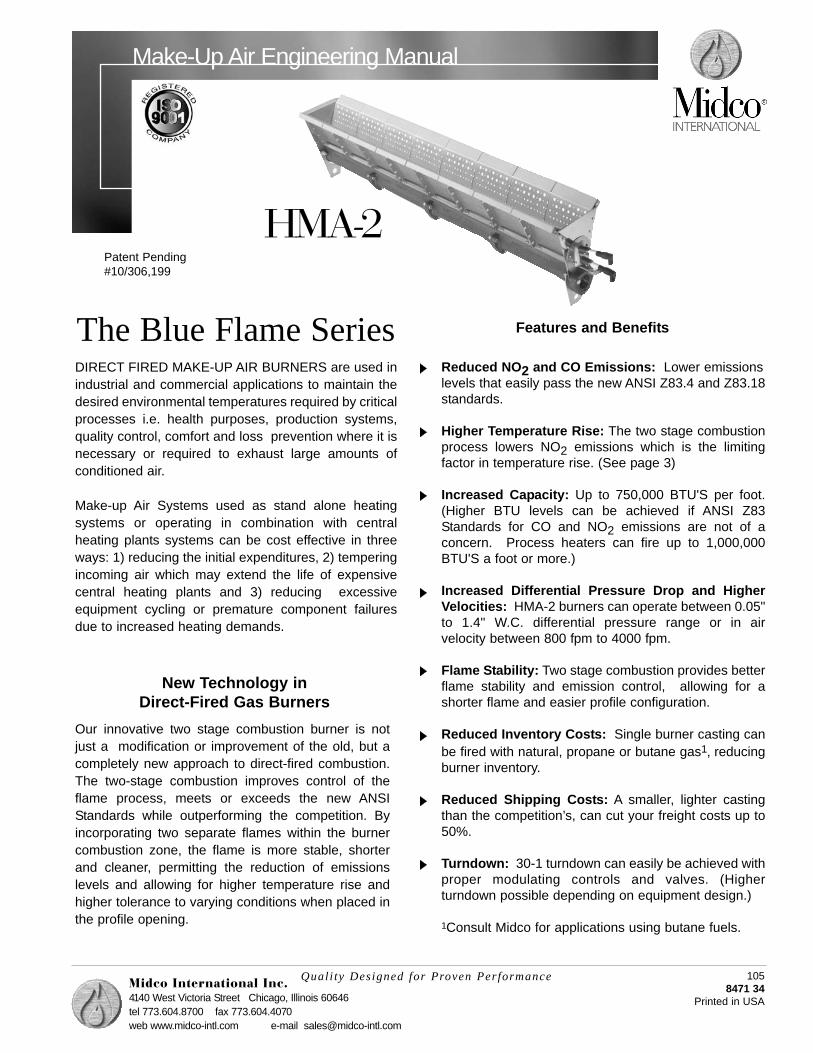
HMA-2
Quali ty Designed for Proven Performance 1058471 34
Printed in USA
Reduced NO2 and CO Emissions: Lower emissions levels that easily pass the new ANSI Z83.4 and Z83.18standards.
Higher Temperature Rise: The two stage combustionprocess lowers NO2 emissions which is the limitingfactor in temperature rise. (See page 3)
Increased Capacity: Up to 750,000 BTU'S per foot.(Higher BTU levels can be achieved if ANSI Z83Standards for CO and NO2 emissions are not of aconcern. Process heaters can fire up to 1,000,000BTU'S a foot or more.)
Increased Differential Pressure Drop and HigherVelocities: HMA-2 burners can operate between 0.05"to 1.4" W.C. differential pressure range or in airvelocity between 800 fpm to 4000 fpm.
Flame Stability: Two stage combustion provides betterflame stability and emission control, allowing for ashorter flame and easier profile configuration.
Reduced Inventory Costs: Single burner casting canbe fired with natural, propane or butane gas1, reducingburner inventory.
Reduced Shipping Costs: A smaller, lighter castingthan the competition’s, can cut your freight costs up to50%.
Turndown: 30-1 turndown can easily be achieved withproper modulating controls and valves. (Higherturndown possible depending on equipment design.)
1Consult Midco for applications using butane fuels.
DIRECT FIRED MAKE-UP AIR BURNERS are used inindustrial and commercial applications to maintain thedesired environmental temperatures required by criticalprocesses i.e. health purposes, production systems,quality control, comfort and loss prevention where it isnecessary or required to exhaust large amounts ofconditioned air.
Make-up Air Systems used as stand alone heatingsystems or operating in combination with centralheating plants systems can be cost effective in threeways: 1) reducing the initial expenditures, 2) temperingincoming air which may extend the life of expensivecentral heating plants and 3) reducing excessiveequipment cycling or premature component failuresdue to increased heating demands.
Our innovative two stage combustion burner is notjust a modification or improvement of the old, but acompletely new approach to direct-fired combustion.The two-stage combustion improves control of theflame process, meets or exceeds the new ANSIStandards while outperforming the competition. Byincorporating two separate flames within the burnercombustion zone, the flame is more stable, shorterand cleaner, permitting the reduction of emissionslevels and allowing for higher temperature rise andhigher tolerance to varying conditions when placed inthe profile opening.
Features and Benefits
New Technology in Direct-Fired Gas Burners
Patent Pending#10/306,199

Specifications
2
*Firing Rate .............................................................. Up to 750,000 Btu/hr/ft 750,000 + Contact Midco
Burner Manifold PressureNatural Gas ................................................. 4.2 to 8 inch W.C. Propane Gas .............................................. 1.6 to 3 inch W.C.
Pilot Capacity ............................................................ 12,000 Btu/hrPilot Manifold Gas Pressure
Natural Gas ................................................. 3.5 inch W.C. Propane Gas .............................................. 2.0 inch W.C. **
Pressure Drop Across the Burner ............................ 0.05 to 1.4 inch W.C.Air Velocity Across the Burner ................................... 800 to 4,000 FPM
Burner Turn-down Ratio ........................................... 30 to 1
Flame Length ............................................................. 10 inches at a full firing rate
* Firing rate is dependent on the pressure across the burner. Please see the includedcharts for recommended burner sizing.** Using a natural gas pilot on propane.
*Burner Configurations *Pilot ConfigurationsPart # Part #
6 inch Straight Section (15.24cm) 1050700 Spark rod and flame rod 11908006 inch Straight Section with Back Inlet (15.24cm) 1230700 Spark rod and UV 120030012 inch Straight Section (30.48cm) 1010700 Remote flame rod 122080012 inch Straight Section with Back Inlet(30.48cm) 1060700 Remote UV 1240800Elbow Section 1070700 Pilot with spark rod only 1210800Tee Section 1080700 Flame rod 1360-03
Spark rod 1342-00
Table 1 - Burner and Pilot Configurations
Midco International Inc. reserves the right to change the construction or configuration of its products atany time.
All information is based on laboratory testing. Different unit size and/or configurations may affect data.
* See Page 15, Figure 1b for configuration reference.
Burner Performance
3
______________________________________________
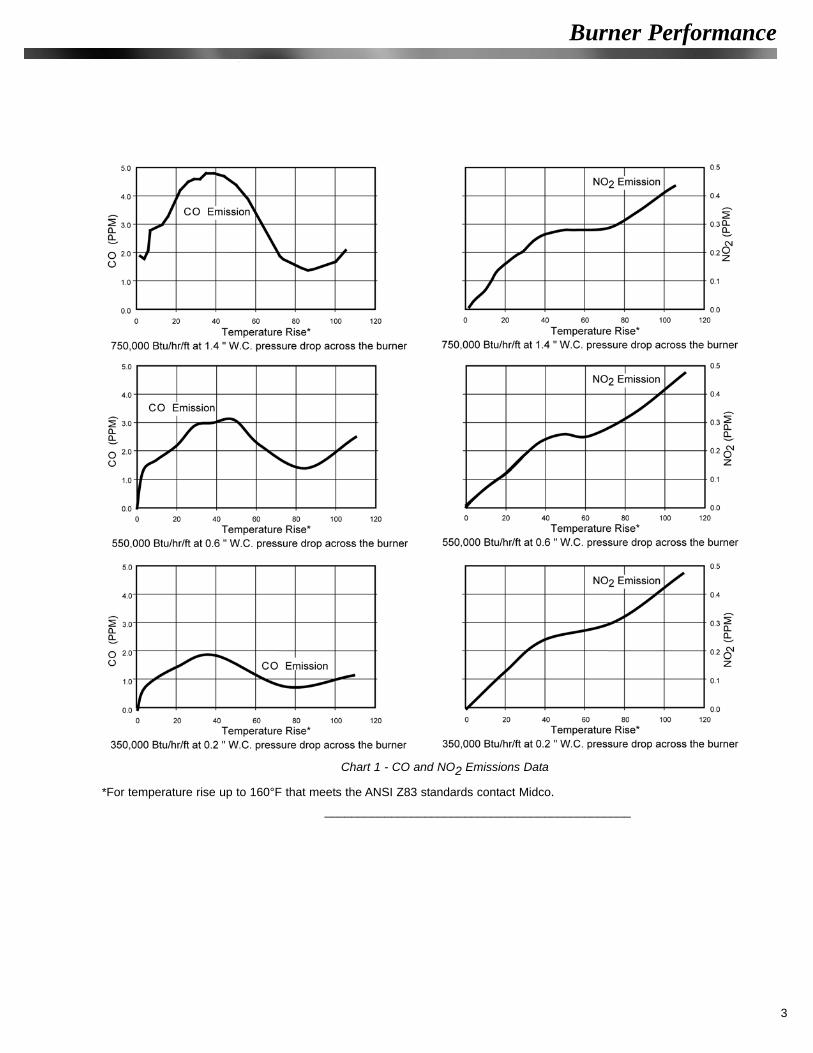
Chart 1 - CO and NO2 Emissions Data
*For temperature rise up to 160°F that meets the ANSI Z83 standards contact Midco.

4
Installation
Chart 3 - BTU's verses Gas Pressure ( " W.C.)
Chart 4 - Pressure Across the Burner verses Profile Velocity
Chart 2 - BTU's verses Pressure Drop

1. Required BTU:BTU/hr = Blower SCFM x Desired Temp. Rise x 1.08
2. Required Burner Length:Feet of burner = [Required BTU/hr]÷[Burner Firing Rate (BTU/hr/ft)] The Burner Firing Rate should correspond to the pressure drop across the burner shown in Chart 2.
3. Required Profile Area:Total Burner Area = Number of burner sections x burner area
Net Profile Area = Rated Fan (SCFM) ÷ Profile Velocity (SFPM)The Profile Velocity can be determined from the following:
Δ P is the pressure drop across the burner
Profile Area = Net Profile Area + Total Burner Area
______________________________________________
Sizing the burner and the corresponding profile for a 5,000 SCFM and a 115 degreestemperature rise.
1. Required BTU:
BTU/hr = Blower SCFM x Desired Temp. Rise x 1.08
BTU/hr =5,000 (SCFM) x 115 (ΔT) x1.08 = 621,000 BTU/hr
2. Required Burner Length:
Feet of burner = [Required BTU/hr]÷[Burner Firing Rate (BTU/hr/ft)]
To determine the optimum burner length we can choose from a combination of 12 inch or 6 inch burner sections referring to Table 1. We can either fire the burner at a rate of 621,000 BTU/hr per ft, or we can fire the burner at 414,000 BTU/hr per ft (1.5 feet of burner). Refer to Chart 3 for the fuel pressures requirements at different firing rates.
3. Required Profile Area:
Total Burner Area = Number of burner sections x burner area
Total Burner Area = 1.0 (ft) x 0.65 = 0.650 ft2Or
Total Burner Area = 1.5 (ft) x 0.65 = 0.975 ft2
5
Profile Setup Example
Profile Setup
Installation
(Burner Section) Burner Area6 inch 0.32 sq. ft.12 inch 0.65 sq. ft.T Section 0.77 sq. ft.Ell Section) 0.65 sq. ft.
(Burner Section) Burner Area6 inch 0.32 sq. ft.12 inch 0.65 sq. ft.T Section 0.77 sq. ft.Ell Section 0.65 sq. ft.

6
InstallationNet Profile Area = Rated Fan (SCFM) ÷ Profile Velocity (SFPM)
The Profile Velocity should be determined based on the burner firing rates. If we choose to fire the burner at 621,000 BTU/hr/ft then the profile opening should be sized for a pressure drop of 0.8 inch W.C. across the burner. If the firing rate is 414,000 BTU/hr/ft then the profile opening should be sized for a pressure drop of 0.4 inch W.C. across the burner. The corresponding profile velocity across the burner should be determined from Chart 4 or use the following equation.
For the 621,000 BTU/hr/ft
Net Profile Area = 5000 (SCFM) ÷ 3086 (SFPM)=1.62ft2
For the 414,000 BTU/hr/ft
Net Profile Area = 5000 (SCFM) ÷ 2182 (SFPM)=2.29ft2
To calculate the profile area needed for both cases:
Profile Area = Net Profile Area + Total Burner Area
For the 621,000 BTU/hr/ft Profile Area = 1.62 + 0.650 = 2.27 ft2
For the 414,000 BTU/hr/ft Profile Area = 2.29 + 0.975 = 3.265 ft2
To calculate the length of the profile opening add burner length to the desired clearance:
For the 621,000 BTU/hr/ft case 12 inch + 4 inch (2 inch on each side) = 16 inch (1.3ft)
For the 414,000 BTU/hr/ft case 18 inch + 4 inch (2 inch on each side) = 22 inch (1.83ft)
To calculate the height of the profile opening divide the profile area by the profile length:
For the 621,000 BTU/hr/ft case 2.27 ft2 ÷ 1.3 ft = 1.75 ft (21 inch)
For the 414,000 BTU/hr/ft case 3.265 ft2 ÷ 1.83 ft = 1.78ft (21.5 inch)
______________________________________________
IMPORTANT: Furnace cement must be used to join and seal all burner casting sections,and end flanges only. If this procedure is not performed, gas leakage will occur. Use10-24x3/8" stainless steel screws and nuts or stainless steel rivets. UNDER NOCIRCUMSTANCES SHOULD STANDARD GRADE HARDWARE OR ALUMINUM RIVETSBE USED.
When assembling Make-Up Air Burners, a few simple but important assembly proceduresmust be followed to insure Burner Performance. Care should be taken when removing,assembling and placing the burner into the heater.
1. Examine the baffles for structural integrity; only new undamaged components should be used.
Profile Setup ExampleContinued
Burner Assembly

2. Assemble individual burner cast iron sections first.3. When joining the baffle sections to the burner casting, place a gasket between the
casting and the baffles, do not tighten the cast iron sections until the entire unit is assembled. Baffles can be riveted together with stainless steel rivets or joined with stainless steel screws.
4. Prepare a mixture of furnace cement thinned to the consistency of a heavy cream.5. Apply furnace cement to both mating surfaces of the burner castings and
end flanges only.6. After sections are joined,wipe off excess furnace cement and make sure you do not clog
any gas or air ports.7. After all baffle plates are tight, secure all baffle plates to the burner casting. Make
sure all bolts and rivets are tight. 8. After all sections are assembled, check for potential gas or air leaks. If necessary,
close up any remaining gaps with furnace cement.9. For high fire start systems, the first adjacent gas port hole (next to the pilot) should be
plugged with furnace cement. See Figure 8 - Pilot Configuration.
______________________________________________
The performance of the HMA-2 burner depends on the unit in which the burner is located.The burner can perform differently in different units and can obtain different end results.Maintaining a relative laminar flow around the burner and providing a sufficient spacebetween the burner and the blower is a key factor in obtaining best burner performance.The unit should be free of any obstructions that can create turbulent effect on the air.
The burner performance is highly dependent on its application and installation in the heater.Factors such as airflow around the burner, burner positioning in the profile , as well as, theprofile sizing have high influence on the final emissions levels . Midco does not guaranteecombustion results prior to performing actual combustion tests.
The burner should be located in the center of the profile. The profile clearance from ends ofthe burner should be kept at approximately 1 to 4-inches. Typically setting the profile 2" fromthe end plates is recommended. Any reinforcements used on the edge of the profile openingshould be on the downstream side of the profile. The burner can be mounted eithervertically or horizontally. Since the airflow varies from unit to unit best results should bedetermined by actual testing.
7
Installation
Burner Placementin the Profile
Note: Any reinforcements around the profile plates should be down stream of the profile plate
Figure 1a - Burner Placement in the Profile

______________________________________________
The HMA-2 Burner is designed to operate in a make-up air heater and in an air streamtaken directly from outdoors. To avoid stratification of the heated air, the burners should belocated on the intake side center to the blower. Such positioning will take advantage of theblower mixing effect and ensure minimum temperature stratification. It will also allow for arelatively uniform airflow across the burner resulting in a clean combustion.
The total pressure of the blower must include allowance for the resistance of the heater andpressure drop across the burner, together with pressure losses at the inlet screen, inletlouvers, filters, plus the external pressure rating of the heater, if any. Contact equipmentmanufacturer for proper information.
______________________________________________8
Installation
Pull-Thru System
Figure 2a - Pull-Thru System
Figure 1b - Burner Placement in the Profile
Figure 2b - Pull-Thru System

The HMA-2 Burner will operate satisfactorily when located downstream of the blower. Amixing plenum may be required at the heater discharge opening to insure minimum temper-ature stratification. Blower and motor selection must be made on the basis of corrections forthe coldest anticipated inlet temperature. In the push-thru system the heater outlet CFM willvary due to the expansion of air.
Push-Thru System
Installation
9
Figure 4 - Installation in a Duct
Figure 5a - Gas Train Assemblies
Figure 3 - Push-Thru System

______________________________________________
10
Installation
Figure 5b - Direct Spark Gas Train Assemblies
Gas Inlet CapacitiesMaximum Feet of Burner
Inlet Size Natural Propane Mfd.1.5 " NPT End Inlet 4' 5' 3'2" NPT Back Inlet 6.5' 8' 4.5'Centrally Located
Table 2 - Gas Inlet Capacities

Burner operation depends on the unit control setup in which the HMA-2 burner is used. Atypical setup should consist of a Flame Safety Control with appropriate air flow proving sys-tem and a Modulating Gas Control System.
1. Verify the pressure across the burner. The pressure across the burner can be measured by placing two static pressure probes, one downstream and one upstream of the profile opening and measure the differential pressure. The pressure should be within burner operating specifications and within the expected calculated pressure.
2. With the burner off check the Flame Safety Air Proving Systema. Check the operation of the air proving system for low and high airflow setting.
Refer to the Specifications of the Flame Safety Control for setup instructions and air switch operational characteristics.
3. Adjust the main gas pressure regulator to the pressure needed for the high fire according to Chart 3. Take into account pressure drops thru the gas valves and other components in the valve train.
4. For continuous, intermittent, or interrupted ignition systemsa. Pipe the pilot gas supply line up stream of the main gas valve.b. Adjust the pilot pressure regulator to 3.5 inch W.C. for Natural Gas or 2.0 inch
W.C. for propane gas.
5. For direct spark ignition system a. Pipe the pilot gas supplied line to the main gas line downstream of the main
gas valve.b. Adjust the pilot pressure regulator to 3.5 inch W.C. for Natural Gas or 2.0 inch
W.C. for propane gas.
6. Depending on the pilot configuration make following adjustments.a. For Spark rod and flame rod configurations
Make sure the flame rod is pointing towards burner manifold.Make sure the flame rod is not touching baffles or burner manifold.Make sure the spark rod is positioned above the pilot gas tube and that it will spark to the end of the gas tube. See Pilot Detail Drawings for this setting on page 16.
b. Spark rod and UV Make sure the spark rod is positioned above the pilot gas tube and that it will spark to the end of the gas tube.
7. Pilot ignitiona. Make sure the main gas valve to the burner is closed for intermittent or
interrupted ignition.b. Observe the pilot flame, the flame should be blue and should extend
approximately to the half of the burner end plate.c. Check the flame signal.
8. Main burner ignitionClose the manual gas valve.
a. Set the Modulating Gas Control System to high fire position.· Slowly open the manual gas valve.· Observe the flame at high fire; the flame should be blue approximately 10
to 12 inches long. If the flame is long, lazy and orange the air to fuel ratio is not correctly adjusted . The pressure across the burner should be increased, refer to Chart 2.
· Check the flame signal.· Check the manifold pressure to the corresponding firing rate. If the manifold
pressure does not correspond to the pressures shown in Chart 3. Check for gas leaks.
Close the manual gas valve.b. Set the Modulating Gas Control System to low fire position.
Slowly open the manual gas valve.· The flame should be evenly extending in the burner.· The flame should be located in the casting of the burner.· Check the flame signal. 11
Burner Installation
Installation

Installation & Trouble ShootingFor a high fire start system the first gas port next to the pilot might require to be blockedusing furnace cement to prevent potential pilot blow outs and flame failures. See page 7(Burner Assembly) and see Figure 8 - Pilot Configuration.
Slight redness and warpage of the baffle plates may occur at the high and intermediate fireinputs. This will not harm the burner. Once an initial discoloration and warp has taken ("set")no further permanent change will take place.
If the end plates redness occurs during high and intermediate fire inputs, the distancebetween the end plates and the profile opening might not be sufficient for the air to cool theend plates. Profile readjustments might be necessary.
______________________________________________
Annual maintenance of HMA-2 burner is recommended to ensure trouble free operation.1. Make sure the system is off2. Inspect the burner baffles for plugged openings
a. Clean baffles with wire brushb. Make sure the baffles are tightly attached to each other and to the burner casting.
3. Inspect the burner casting for plugged openingsa. Clean casting with wire brushb. If necessary re-drill gas ports with a 1/8" (0.125") drill size and air ports with a number
43 (0.089") drill size. 4. Turn the system on and visually inspect the flame.5. For Service Bulletins on the cleaning and maintenance of burners contact Midco.
______________________________________________
The Midco HMA-2 Burner is only a component of the complete system. For trouble shootingof the equipment contact the OEM (Original Equipment Manufacturer) or the componentmanufacturer.
If the pilot fails to light, install a manometer on the pilot pressure tap. Check for 3.5" W.C.for natural gas or 2" W.C. for propane. If no gas check for voltage to pilot solenoid valve. Ifno voltage check operating controls or primary flame safeguard. If voltage to pilot solenoidvalve is present and if there is 3.5" W.C. gas pressure at pilot pressure tap then check forspark or flame rod settings. If there is no voltage to pilot solenoid valve, refer to FlameSafety control specifications or contact the original equipment manufacturer.
If Main Burner fails: If no main flame check manifold pressure. If no manifold pressurecheck for voltage to the gas solenoid valve and check if main manual valve is open. If novoltage to gas valve refer to Flame Safety control specifications or contact the originalequipment manufacturer.
If the pilot fails as main gas valves open, the first adjacent gas port hole (next to the pilot)should be plugged with furnace cement. See Figure 8 - Pilot Configuration.
______________________________________________
12
Burner InstallationContinued
Burner Maintenance
Trouble Shooting
I.
II.
III.
IV.

13
Burner Configuration
Figure 6 - Burner Sections - Assembly

14
Parts - Isometric View
Figu
re 7
- B
urne
r Ass
embl
y P
arts
- Is
omet
ric V
iew

Parts List for Isometric View
Bur
ner C
onfig
urat
ion
6" S
traig
ht
6" B
ack
Inle
t12
" Stra
ight
12" B
ack
Inle
t E
ll S
ectio
n Te
e S
ectio
n P
art N
umbe
r13
59-0
913
98-0
513
64-0
513
61-0
713
62-0
713
65-0
6Ite
mN
o.P
art D
escr
iptio
nP
art N
oQ
uant
ityQ
uant
ityQ
uant
ityQ
uant
ityQ
uant
ityQ
uant
ity1
Bur
ner C
astin
g1
11
11
1 2
HM
A-2
6" B
affle
1395
-23
22
44
22
HM
A-2
Tee
Baf
fle13
95-1
11
2H
MA
-2 O
utsi
de C
orne
r Baf
fle
1395
-35
13
HM
AB
lank
End
Pla
te13
54-5
0 1
11
11
24
HM
AP
ilot E
nd P
late
1354
-60
11
11
11
5P
ilot
See
pilo
t lis
ting
on P
age
16 -
Pilo
t Con
figur
atio
n (F
or s
elec
tion)
6B
affle
Cla
mp
1356
-00
22
44
22
7In
side
Baf
fle C
lam
p13
56-1
02
48
Bla
nk F
lang
e13
72-0
21
11
11
29
Inle
t Fla
nge
(Tap
ered
)13
52-0
2 1
11
11
110
Sup
port
Bra
cket
1374
-00
22
22
23
115/
16-1
8x1-
1/2
Hex
H
ead
Cap
Scr
ew6
66
66
912
5/16
Loc
k W
ashe
r6
66
66
913
5/16
-18
Bra
ss H
ex N
ut6
66
66
914
10-2
4x9/
16 P
hilli
ps R
d H
d S
.S. M
ach
Scr
ew4
48
88
1215
S62
Ste
el R
ivet
Bod
y12
1222
2222
25
Tabl
e 3
- Bur
ner A
ssem
bly
Par
ts L
ist
15

______________________________________________
1. Conversion of SCFM to Actual CFM of air
SCFM = CFM x ρ_____
0.075
2. Air density as a function of Temperature -- ρ = 1.35 x Barometric Pressure (in Hg)____________________
T (out)
+ 460
3. Change in Standard Barometric Pressure as a function of Altitude
Barometric Pressure (in.Hg) = 29.921x (1_6.8753 x 0.000001x altitude (ft))∧5.2559
4. Temperature difference -- Temperature Rise = T(out)- T(in)
5. Energy equation - - BTU/hr = SCFM x Temperature Rise x 1.08
Where: 1.08 is a sensible heat equation constant
1.08 = 0.2397 ( BTU ) x 60 ( min) x 0.075 ( lb )_____ ___ ___lb H ft3
16105
8471 34Printed in USA
Midco International Inc. 4140 West Victoria Street * Chicago, Illinois 60646tel 773.604.8700 fax 773.604.4070 web www.midco-intl.com email [email protected]
Figure 8 - Pilot Configuration
Parts - Pilot Configuration & Mounting / Equation Reference
Equation Reference