Embed Size (px)
Citation preview

HM Quickshifter GP
andHM Quickshifter GP Configuration Tool
User's Guide2013
HM Quickshifter GP User's Guide
Table of Contents -- Page 2 of 81 Copyright © 2014 HM Quickshifter UK, Ltd.
Table of Contents
The HM Quickshifter GP ..................................................................................................................2Different Kill Times for Different Gears ......................................................................................3Deriving Gear Position ................................................................................................................4HM Seamless Shift Technology (HMSS) ....................................................................................5Features at a Glance ..................................................................................................................5Wiring Guide ...............................................................................................................................6HM Quickshifter GP Part Numbering .........................................................................................8HM Quickshifter GP Accessories / Spares .................................................................................9
HM Quickshifter GP Configuration Tool .........................................................................................10Software Installation ..................................................................................................................11
Welcome ..............................................................................................................................12Installation Options .............................................................................................................13Confirmation ........................................................................................................................15Installation Completed ........................................................................................................16
Overview ...................................................................................................................................17Important Definitions ...........................................................................................................18Connecting to the Shifter ....................................................................................................18Navigating the Application ..................................................................................................19Saving Configuration to a File ............................................................................................24
Tab Reference ...........................................................................................................................25Overview Tab ......................................................................................................................26Input Tab .............................................................................................................................28Gears Tab ...........................................................................................................................30HMSS Tab ...........................................................................................................................33Shift -- Basic Settings Tab ..................................................................................................38Shift -- Power Reintroduction Tab ......................................................................................40Shift -- Power Reintroduction Strategies Tab .....................................................................43Blip Tab ...............................................................................................................................45Shift/Blip Common Tab .......................................................................................................47Outputs Tab .........................................................................................................................50CAN Tab ..............................................................................................................................52Failsafes Tab .......................................................................................................................59Logging Tab ........................................................................................................................62
After Event Log Is Loaded ...........................................................................................64Stats Tab .............................................................................................................................67Firmware Tab ......................................................................................................................68
Step 1: Load Hex File ..................................................................................................69Step 2: Firmware Is Written and Validated ...................................................................71Step 3: Firmware Update Completed ...........................................................................73
Training the Shifter ...................................................................................................................75Training Phase 1 .................................................................................................................76Training Phase 2 .................................................................................................................78Training Completed .............................................................................................................79
Credits .............................................................................................................................................80
HM Quickshifter GP User's Guide
Copyright © 2014 HM Quickshifter UK, Ltd. Different Kill Times for Different Gears -- Page 3 of 81
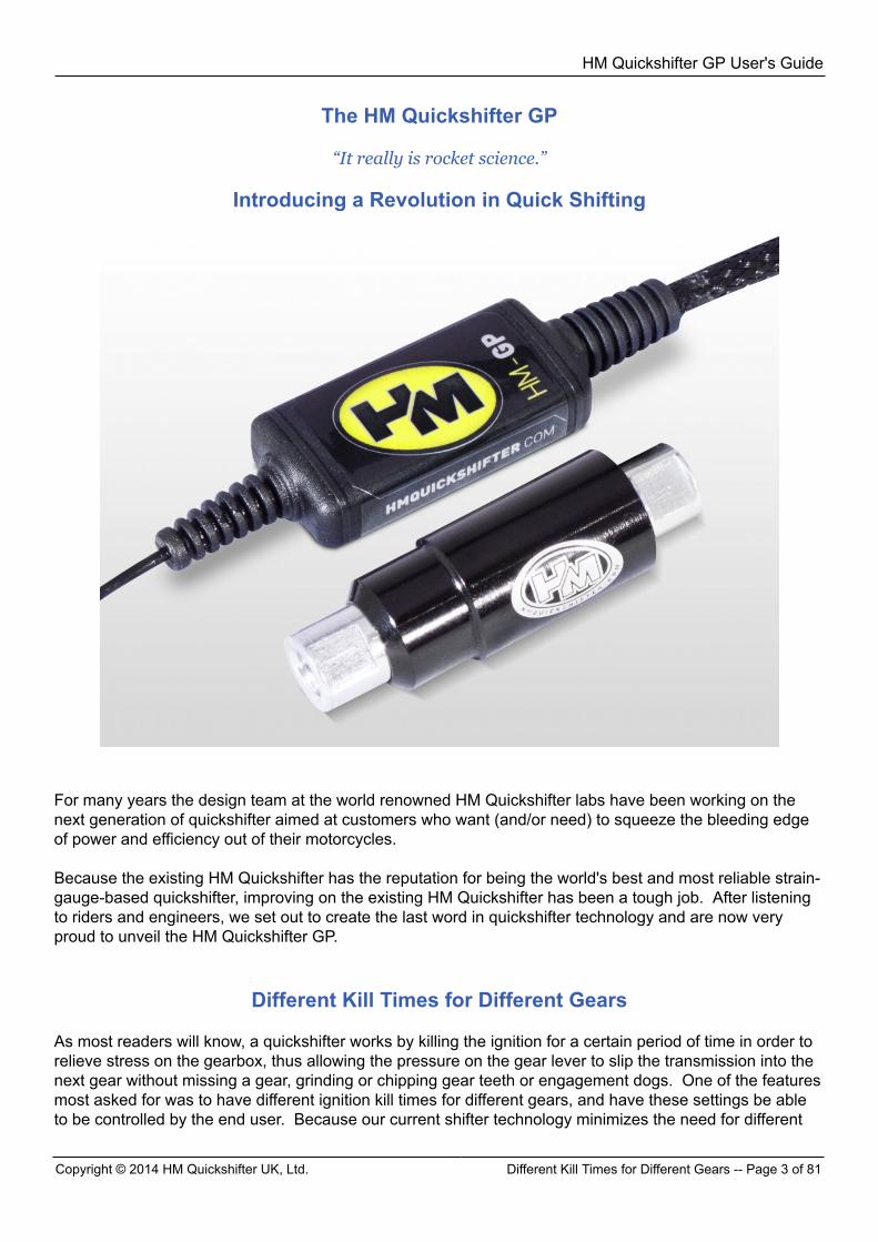
The HM Quickshifter GP
“It really is rocket science.”
Introducing a Revolution in Quick Shifting
For many years the design team at the world renowned HM Quickshifter labs have been working on thenext generation of quickshifter aimed at customers who want (and/or need) to squeeze the bleeding edgeof power and efficiency out of their motorcycles. Because the existing HM Quickshifter has the reputation for being the world's best and most reliable strain-gauge-based quickshifter, improving on the existing HM Quickshifter has been a tough job. After listeningto riders and engineers, we set out to create the last word in quickshifter technology and are now veryproud to unveil the HM Quickshifter GP.
Different Kill Times for Different Gears
As most readers will know, a quickshifter works by killing the ignition for a certain period of time in order torelieve stress on the gearbox, thus allowing the pressure on the gear lever to slip the transmission into thenext gear without missing a gear, grinding or chipping gear teeth or engagement dogs. One of the featuresmost asked for was to have different ignition kill times for different gears, and have these settings be ableto be controlled by the end user. Because our current shifter technology minimizes the need for different
HM Quickshifter GP User's Guide
Deriving Gear Position -- Page 4 of 81 Copyright © 2014 HM Quickshifter UK, Ltd.
kill times (the technical reasons for which are both lengthy and secret), this has been a subject of intenseresearch and discussion. The culmination of this research is that it is now clear that the need for differentkill times for different gears is important in certain situations: for example, world-class racing where everyadditional millisecond of power to the rear wheel may make the difference between winning and losing. Sowe decided from the outset to incorporate this capability as a core part of our new flagship design.
Deriving Gear Position
Having different kill times for different gears as a core part of our new flagship design brought on its ownchallenges, in particular correctly detecting the gear position. If the shifter is going to be our flagshipproduct, then it must operate with the same unbreakable robustness and absolute consistency that ourcurrent shifters are renowned for. The trouble is that something seemingly as simple as calculating gearposition is, in fact, a very difficult challenge. The way most existing such devices work (including our HMDash) is by computing the ratio between speed and RPM to derive gear. This is fine for a dash display butnot, in our view, good enough for a high precision device that relies on perfectly correct information. Chainchatter, firing order, rev limiters, clutch slip and traction control can all fool this type of calculation. The problem is actually worse than it initially seems. Take for example 6th gear. If the bike is in 6th gearthen it would be desirable to prevent a shift from happening if the rider inadvertently tries to select a non-existent 7th gear. This is something we know many riders do – something that we have seen in datalogging time and time again. The purpose, of course, is to prevent a time- and power-killing "false" shift ifthe rider does this. But what happens if the bike is actually in 5th and the shifter is "one off" and thinks itis in 6th? The rider will be prevented from shifting to 6th – not acceptable by any measure, and by usingcurrent techniques this is a very real danger. Another example is the shift from 1st to 2nd. On most gearboxes the kill time required for 1st to 2nd gearchanges is significantly longer than from 2nd to 3rd for example. So again, if the bike is in 1st gear but theshifter thinks it is in second gear, then a very rough or missed shift may take place, likely causing gearboxdamage! Also consider the case of short shifting or multiple fast gear changes (with or without clutch): again currentcalculation techniques are relatively slow, so this is yet another area that the shifter could be fooled. As theastute reader may have surmised, this is NOT just a matter of adding 1 for each up-shift, and subtracting 1for each down-shift! The gear actually must be verified with no assumptions made. Add all of this together and it is easy to see our hesitation in including this in a product where absoluteconsistency for professional use is paramount. While is it true that there are ways of "smoothing over" or masking current techniques so that the effectis, on the whole, acceptable – these do not give the kind of confidence in a product that we have becomeused to, or as demanded (and expected) at the highest levels of racing. After a lot of research by some very highly qualified people we put together a technical specification thatdemanded 100% accuracy with respect to gear position. Part of this specification was that even 99.99%was not good enough. Another requirement for gear position was that the shifter needed near instantresults in real time – a big requirement! A team of mathematical engineering specialists worked on thisproblem for nearly two years. The answer lay in use of predictive mathematics, namely in the form of aspecially-adapted non-linear time domain version of a Kalman Filter – the same type of math that predictsfinancial markets, tracks fast-moving military targets, and steers missiles. A sledge hammer to crack anut? Perhaps, but it works, and it works wonderfully. When a gear change is made, the result – measuredand verified without any assumptions – is accurately computed within 2-3 meters of completion of the shift.
HM Quickshifter GP User's Guide
Copyright © 2014 HM Quickshifter UK, Ltd. HM Seamless Shift Technology (HMSS) -- Page 5 of 81
At 250 KMH, the typical delay between the completed shift and the gear being known with certainty ismeasurable in milliseconds! THAT is world class, and as far as we know, hasn't been achieved anywhereelse in the world. At that speed, the time required to "know" the gear position with certainty compares tobikes with built in analog-type rotary gear position sensors! We have pumped hundreds of thousands of logged simulation, road, and race miles through theHM Quickshifter GP and have had a 0% failure rate on computing the correct gear. Thus, we are very proud of what we have here – an industry first: absolutely reliable and consistent gearposition whatever the circumstances. In addition, the HM Quickshifter GP does NOT require setup – it learns the gears on its own. Thiscompletely removes the possibility of accidentally selecting or inputting incorrect ratios. It also means thatin high pressure situations where, for example, internal gear ratios must be changed quickly, there is noextra demand on the engineers to reprogram the shifter – it will automatically detect the changed ratio(s)and adjust itself accordingly. This is in keeping with our company philosophy of providing exceedingly high-tech products that are verysimple to use and very hard to use incorrectly. Having explained in detail about the gear position calculation, we hope that it has set the tone of the levelof each aspect of the HM Quickshifter GP: truly a masterpiece of engineering, worthy of living in themedical or aerospace industry.
HM Seamless Shift Technology (HMSS) The HM Quickshifter GP has programmable kill times for each gear going up and separately going downthe gearbox. However on top of this we have the new revolutionary HMSS system. This system usesintensive and very advanced mathematics and digital signal processing (DSP) to identify when the actualdogs – the gear teeth – have fully engaged. This nullifies the requirement for kill times and not onlyensures the shortest possible kill times it also ensures the smoothest and safest gear change. This isbecause regardless of the conditions, load, RPM, and gearbox characteristics, it detects when the nextgear is actually engaged and then reapplies power. This is a massive step forwards in shifting technologyand has made all other shifting products obsolete. There are also safety programmable minimum and maximum kill times which override this algorithm inthe rare case that the rider/bike is doing something very unusual and for some reason the shifter doesnot correctly detect this gear engagement in a timely fashion. Typically a kill time is a crude parameterthat must be significantly longer than the actual gear change time due to the vast range of different gearchanging conditions, this directly translates to slower lap times, less smooth gear changes, more wear onthe gearbox and the potential for a missed gear if the rider / bike do something unusual and end up takinglonger to mechanically shift than the allowed kill time. In short, HMSS is a revolution in changing gears! Not just a gimmick – this is the culmination of thousandsof hours of work by contracted specialists in their field.
Features at a Glance
Since we required heavy 32bit RISC processing horse power to perform the gear and HMSS calculations, itmeant that we had a lot of horse power to perform other functions.
HM Quickshifter GP User's Guide
Wiring Guide -- Page 6 of 81 Copyright © 2014 HM Quickshifter UK, Ltd.
The following is a summary of the HM Quickshifter GP's features:
• Fully and continuously dynamic self learning, very fast and incredibly accurate geardetermination
• HMSS System to beat chosen shift times to save significant accumulated time over a lap andprovide seemingly seamless shifts.
• Multiple types of outputs, all easily programmable• Built in full feature Blipper controller for down shifting (This is not a blipper, but configuration and
output for an external blipper.)• Each gear has its own kill time and its own sensitivity• Millisecond accuracy on kill times • Highly intelligent real-time fault analysis and configurable error strategy. Policy: never allow
even a smashed shifter to cause total motorcycle failure• Easily readable, detailed and cyclic event log• Data logging• Firmware updateable via USB from a Windows computer or tablet• Highly sophisticated feedback derived kill time augmentation – unbeatable for lap time saved• Advanced feedback derived power cutting / introduction strategies• CAN Interface (via CAN transceiver [under development]) to allow connection to ECU’s / Dashes
or other Logging or Display Equipment for delivering data or recording data.• Simple USB interface (No Drivers! Just plug into any Windows Operating System and play!)• Professional Level Fully Programmable Traction Control using custom Kalman Algorithm (under
development) • Very Low power for a heavy weight 32bit RISC processor (30mA) • Highly resilient power supply, able to operate up to 80v and can withstand transients far in excess
of automotive standards• Very small size• Low Cost• HM’s 24/7 professional support• Ultra light weight
HM Quickshifter GP User's Guide
Copyright © 2014 HM Quickshifter UK, Ltd. Wiring Guide -- Page 7 of 81
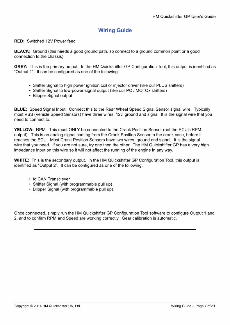
Wiring Guide RED: Switched 12V Power feed BLACK: Ground (this needs a good ground path, so connect to a ground common point or a goodconnection to the chassis). GREY: This is the primary output. In the HM Quickshifter GP Configuration Tool, this output is identified as“Output 1”. It can be configured as one of the following:
• Shifter Signal to high power ignition coil or injector driver (like our PLUS shifters)• Shifter Signal to low-power signal output (like our PC / MOTOx shifters)• Blipper Signal output
BLUE: Speed Signal Input. Connect this to the Rear Wheel Speed Signal Sensor signal wire. Typicallymost VSS (Vehicle Speed Sensors) have three wires, 12v, ground and signal. It is the signal wire that youneed to connect to. YELLOW: RPM. This must ONLY be connected to the Crank Position Sensor (not the ECU's RPMoutput). This is an analog signal coming from the Crank Position Sensor in the crank case, before itreaches the ECU. Most Crank Position Sensors have two wires, ground and signal. It is the signalwire that you need. If you are not sure, try one then the other. The HM Quickshifter GP has a very highimpedance input on this wire so it will not affect the running of the engine in any way. WHITE: This is the secondary output. In the HM Quickshifter GP Configuration Tool, this output isidentified as “Output 2”. It can be configured as one of the following:
• to CAN Transciever• Shifter Signal (with programmable pull up)• Blipper Signal (with programmable pull up)
Once connected, simply run the HM Quickshifter GP Configuration Tool software to configure Output 1 and2, and to confirm RPM and Speed are working correctly. Gear calibration is automatic.
HM Quickshifter GP User's Guide
HM Quickshifter GP Part Numbering -- Page 8 of 81 Copyright © 2014 HM Quickshifter UK, Ltd.
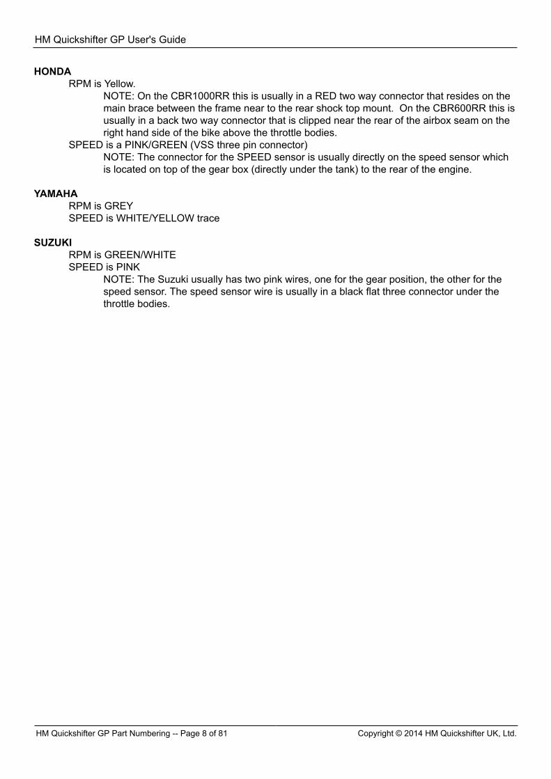
HONDARPM is Yellow.
NOTE: On the CBR1000RR this is usually in a RED two way connector that resides on themain brace between the frame near to the rear shock top mount. On the CBR600RR this isusually in a back two way connector that is clipped near the rear of the airbox seam on theright hand side of the bike above the throttle bodies.
SPEED is a PINK/GREEN (VSS three pin connector)NOTE: The connector for the SPEED sensor is usually directly on the speed sensor whichis located on top of the gear box (directly under the tank) to the rear of the engine.
YAMAHA
RPM is GREYSPEED is WHITE/YELLOW trace
SUZUKI
RPM is GREEN/WHITESPEED is PINK
NOTE: The Suzuki usually has two pink wires, one for the gear position, the other for thespeed sensor. The speed sensor wire is usually in a black flat three connector under thethrottle bodies.
HM Quickshifter GP User's Guide
Copyright © 2014 HM Quickshifter UK, Ltd. HM Quickshifter GP Accessories / Spares -- Page 9 of 81
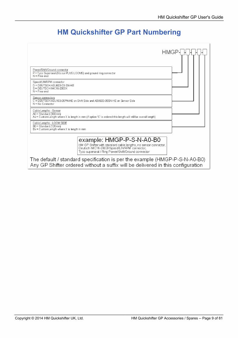
HM Quickshifter GP Part Numbering
HM Quickshifter GP User's Guide
HM Quickshifter GP Configuration Tool -- Page 10 of 81 Copyright © 2014 HM Quickshifter UK, Ltd.
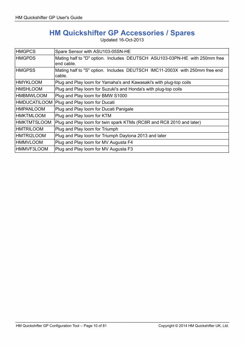
HM Quickshifter GP Accessories / SparesUpdated 16-Oct-2013
HMGPCS Spare Sensor with ASU103-05SN-HEHMGPDS Mating half to "D" option. Includes DEUTSCH ASU103-03PN-HE with 250mm free
end cable.HMGPSS Mating half to "S" option. Includes DEUTSCH IMC11-2003X with 250mm free end
cable.HMYKLOOM Plug and Play loom for Yamaha's and Kawasaki's with plug-top coilsHMSHLOOM Plug and Play loom for Suzuki's and Honda's with plug-top coilsHMBMWLOOM Plug and Play loom for BMW S1000HMDUCATILOOM Plug and Play loom for DucatiHMPANLOOM Plug and Play loom for Ducati PanigaleHMKTMLOOM Plug and Play loom for KTMHMKTMTSLOOM Plug and Play loom for twin spark KTMs (RC8R and RC8 2010 and later)HMTRILOOM Plug and Play loom for TriumphHMTRI2LOOM Plug and Play loom for Triumph Daytona 2013 and laterHMMVLOOM Plug and Play loom for MV Augusta F4HMMVF3LOOM Plug and Play loom for MV Augusta F3
HM Quickshifter GP User's Guide
Copyright © 2014 HM Quickshifter UK, Ltd. Software Installation -- Page 11 of 81
HM Quickshifter GP Configuration Tool
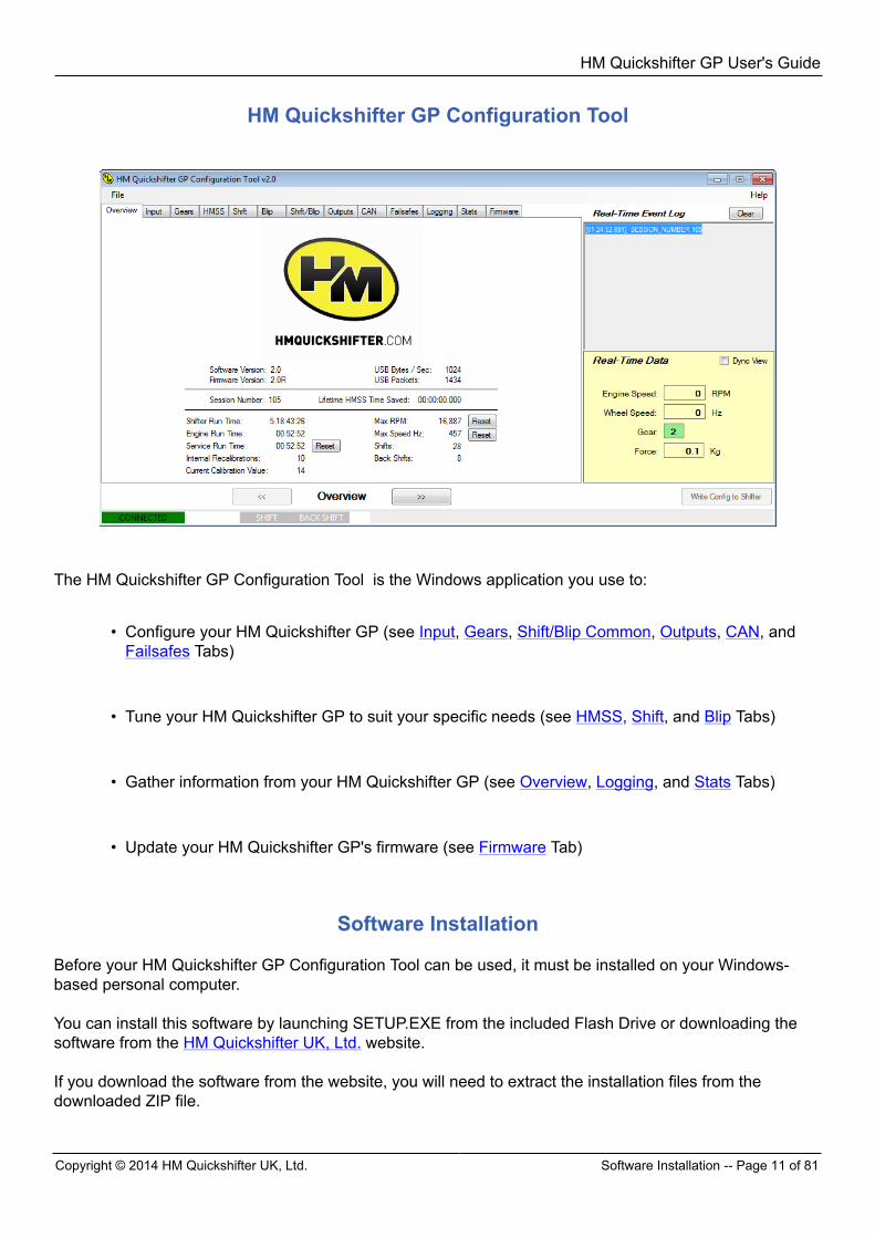
The HM Quickshifter GP Configuration Tool is the Windows application you use to:
• Configure your HM Quickshifter GP (see Input, Gears, Shift/Blip Common, Outputs, CAN, andFailsafes Tabs)
• Tune your HM Quickshifter GP to suit your specific needs (see HMSS, Shift, and Blip Tabs)
• Gather information from your HM Quickshifter GP (see Overview, Logging, and Stats Tabs)
• Update your HM Quickshifter GP's firmware (see Firmware Tab)
Software Installation Before your HM Quickshifter GP Configuration Tool can be used, it must be installed on your Windows-based personal computer. You can install this software by launching SETUP.EXE from the included Flash Drive or downloading thesoftware from the HM Quickshifter UK, Ltd. website. If you download the software from the website, you will need to extract the installation files from thedownloaded ZIP file.

HM Quickshifter GP User's Guide
Welcome -- Page 12 of 81 Copyright © 2014 HM Quickshifter UK, Ltd.
Finally, when you have SETUP.EXE and the "GP_Shifter_Configuration_Tool_Installer...msi" file in thesame folder, launch SETUP.EXE by double-clicking it, and proceed through the installation. (Note on aWindows 7 or Windows 8 computer, you may need to right click the SETUP.EXE file and select "Run AsAdministrator".) The installation will proceed in the sequence of the links below.
HM Quickshifter GP User's Guide
Copyright © 2014 HM Quickshifter UK, Ltd. Installation Options -- Page 13 of 81
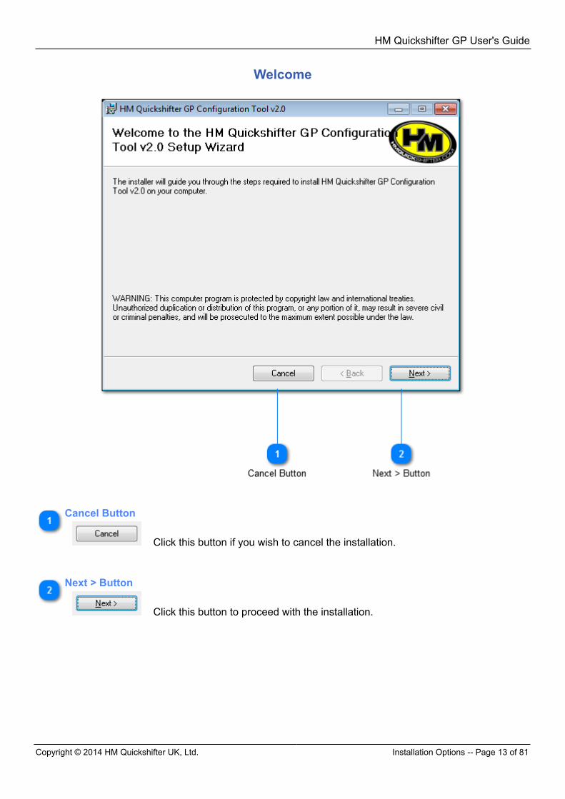
Welcome
Cancel Button
Click this button if you wish to cancel the installation.
Next > Button
Click this button to proceed with the installation.
HM Quickshifter GP User's Guide
Installation Options -- Page 14 of 81 Copyright © 2014 HM Quickshifter UK, Ltd.
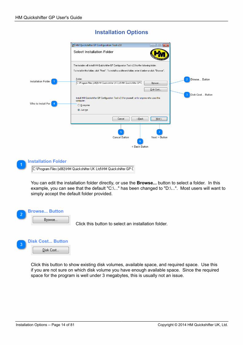
Installation Options
Installation Folder
You can edit the installation folder directly, or use the Browse... button to select a folder. In thisexample, you can see that the default "C:\..." has been changed to "D:\...". Most users will want tosimply accept the default folder provided.
Browse... Button
Click this button to select an installation folder.
Disk Cost... Button
Click this button to show existing disk volumes, available space, and required space. Use thisif you are not sure on which disk volume you have enough available space. Since the requiredspace for the program is well under 3 megabytes, this is usually not an issue.
HM Quickshifter GP User's Guide
Copyright © 2014 HM Quickshifter UK, Ltd. Confirmation -- Page 15 of 81
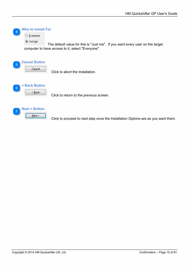
Who to Install For
The default value for this is "Just me". If you want every user on the targetcomputer to have access to it, select "Everyone".
Cancel Button
Click to abort the installation.
< Back Button
Click to return to the previous screen.
Next > Button
Click to proceed to next step once the Installation Options are as you want them.
HM Quickshifter GP User's Guide
Installation Completed -- Page 16 of 81 Copyright © 2014 HM Quickshifter UK, Ltd.
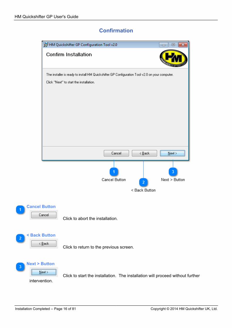
Confirmation
Cancel Button
Click to abort the installation.
< Back Button
Click to return to the previous screen.
Next > Button
Click to start the installation. The installation will proceed without furtherintervention.
HM Quickshifter GP User's Guide
Copyright © 2014 HM Quickshifter UK, Ltd. Overview -- Page 17 of 81
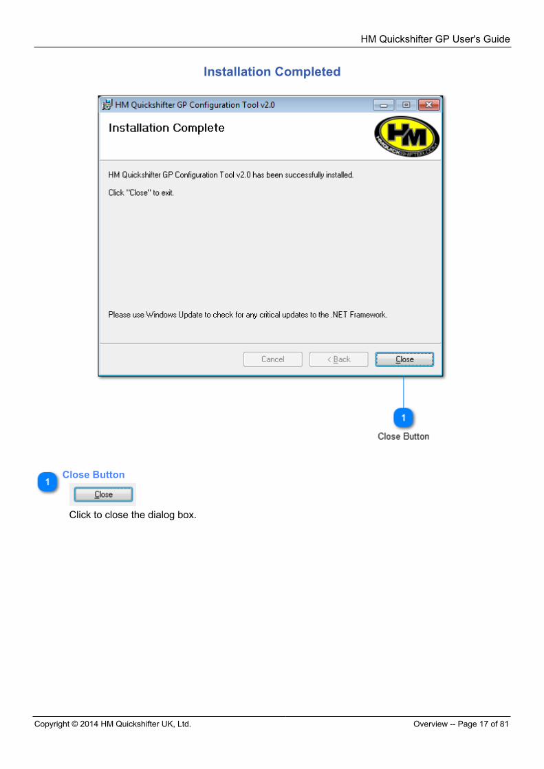
Installation Completed
Close Button
Click to close the dialog box.
HM Quickshifter GP User's Guide
Important Definitions -- Page 18 of 81 Copyright © 2014 HM Quickshifter UK, Ltd.
Overview
The below topics provide an overview of the HM Quickshifter GP Configuration Tool application.
Important Definitions
Shift In this application, the term "shift" ALWAYS means an up-shift -- shifting from a lower gear to a higher gear. This is the HM Quickshifter GP's primary function, which is to assist the rider in achieving the fastestpossible shifts, getting power back to the rear wheel as fast as feasible while still performing reliable,smooth shifts. Blip In this application, the term "blip" ALWAYS means the action the HM Quickshifter GP performs to executea back-shift. If the hardware for it is connected, the HM Quickshifter GP is capable of assisting with back-shifts. When it is configured to do so, a second output may be used to signal throttle "blipping" hardware,which momentarily applies the throttle while decelerating in order to relieve strain on the gearbox toachieve a back-shift. CAN CAN stands for "Controller Area Network", and is a common and reliable data transmission network used inthe automotive and other industries. (See Controller Area Network definition on Wikipedia.) If the CAN Transceiver is connected to the HM Quickshifter GP's "Output 2" wire, the HM Quickshifter GPcan be configured to transmit a wide variety of data to a CAN network. Such devices might include adashboard, data logger, or any other device that is capable of accepting CAN data. See CAN Tab for more information.
Connecting to the Shifter
In the lower left corner of the HM Quickshifter GP Configuration Tool application is the CONNECTEDindicator. When the HM Quickshifter GP is not connected to the computer, the CONNECTED indicator hasa red background and displays "NOT CONNECTED".
Once the Shifter is powered on and connected to the PC via USB cable, the CONNECTED indicatorchanges to a green background and displays "CONNECTED".
When this happens, the HM Quickshifter GP Configuration Tool automatically reads and displays theHM Quickshifter GP's configuration.

HM Quickshifter GP User's Guide
Copyright © 2014 HM Quickshifter UK, Ltd. Navigating the Application -- Page 19 of 81
Note that if the HM Quickshifter GP is powered on AFTER the USB cable is attached, you will hear theUSB device-connect tone from the PC twice. This is normal. After the second tone, you may configureand tune your HM Quickshifter GP as usual.
HM Quickshifter GP User's Guide
Navigating the Application -- Page 20 of 81 Copyright © 2014 HM Quickshifter UK, Ltd.
Navigating the Application
HM Quickshifter GP User's Guide
Copyright © 2014 HM Quickshifter UK, Ltd. Navigating the Application -- Page 21 of 81
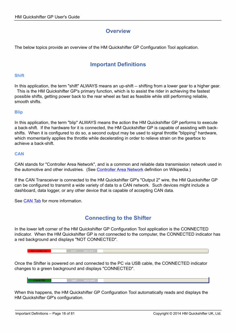
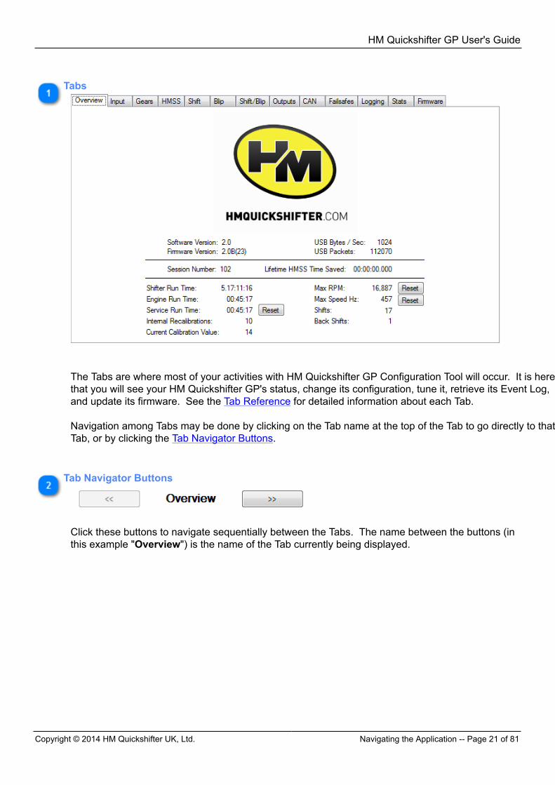
Tabs
The Tabs are where most of your activities with HM Quickshifter GP Configuration Tool will occur. It is herethat you will see your HM Quickshifter GP's status, change its configuration, tune it, retrieve its Event Log,and update its firmware. See the Tab Reference for detailed information about each Tab. Navigation among Tabs may be done by clicking on the Tab name at the top of the Tab to go directly to thatTab, or by clicking the Tab Navigator Buttons.
Tab Navigator Buttons
Click these buttons to navigate sequentially between the Tabs. The name between the buttons (inthis example "Overview") is the name of the Tab currently being displayed.

HM Quickshifter GP User's Guide
Navigating the Application -- Page 22 of 81 Copyright © 2014 HM Quickshifter UK, Ltd.
Real-Time Event Log Panel
This area displays events that occur inside the HM Quickshifter GP as they happen. A time stampis displayed on the left of each log entry indicating the amount of time that has elapsed since theHM Quickshifter GP was powered up. Its format is
<hours>:<minutes>:<seconds>.<milliseconds> Click the Clear button to clear the displayed list of events.
Status Bar
The Status Bar indicates certain statuses at any given moment: CONNECTED Indicator: Indicates whether a powered-on HM Quickshifter GP is connected to thecomputer via USB cable. See Connecting to the Shifter for more information. FAILSAFE Indicator: The white rectangle to the right of the CONNECTED indicator flashes "FAILSAFE" ifthe HM Quickshifter GP has entered Failsafe Mode. See Failsafes Tab for more information. SHIFT Indicator: The white letters "SHIFT" flash red momentarily when the HM Quickshifter GP hasperformed a Shift. BACK SHIFT Indicator: The white letters "BACK SHIFT" flash red momentarily when theHM Quickshifter GP has performed a Blip.
HM Quickshifter GP User's Guide
Copyright © 2014 HM Quickshifter UK, Ltd. Navigating the Application -- Page 23 of 81
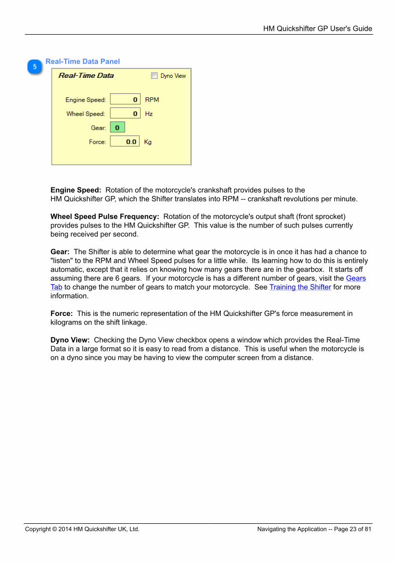
Real-Time Data Panel
Engine Speed: Rotation of the motorcycle's crankshaft provides pulses to theHM Quickshifter GP, which the Shifter translates into RPM -- crankshaft revolutions per minute. Wheel Speed Pulse Frequency: Rotation of the motorcycle's output shaft (front sprocket)provides pulses to the HM Quickshifter GP. This value is the number of such pulses currentlybeing received per second. Gear: The Shifter is able to determine what gear the motorcycle is in once it has had a chance to"listen" to the RPM and Wheel Speed pulses for a little while. Its learning how to do this is entirelyautomatic, except that it relies on knowing how many gears there are in the gearbox. It starts offassuming there are 6 gears. If your motorcycle is has a different number of gears, visit the GearsTab to change the number of gears to match your motorcycle. See Training the Shifter for moreinformation. Force: This is the numeric representation of the HM Quickshifter GP's force measurement inkilograms on the shift linkage. Dyno View: Checking the Dyno View checkbox opens a window which provides the Real-TimeData in a large format so it is easy to read from a distance. This is useful when the motorcycle ison a dyno since you may be having to view the computer screen from a distance.
HM Quickshifter GP User's Guide
Saving Configuration to a File -- Page 24 of 81 Copyright © 2014 HM Quickshifter UK, Ltd.
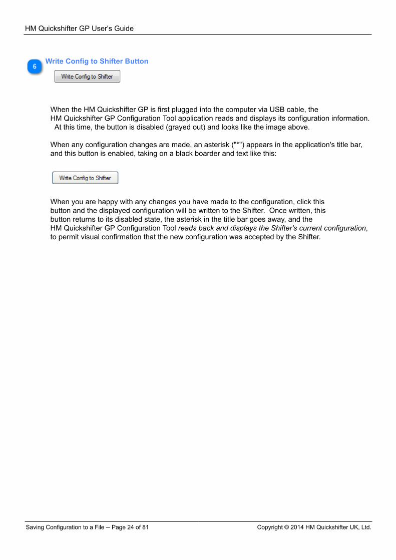
Write Config to Shifter Button
When the HM Quickshifter GP is first plugged into the computer via USB cable, theHM Quickshifter GP Configuration Tool application reads and displays its configuration information. At this time, the button is disabled (grayed out) and looks like the image above. When any configuration changes are made, an asterisk ("*") appears in the application's title bar,and this button is enabled, taking on a black boarder and text like this:
When you are happy with any changes you have made to the configuration, click thisbutton and the displayed configuration will be written to the Shifter. Once written, thisbutton returns to its disabled state, the asterisk in the title bar goes away, and theHM Quickshifter GP Configuration Tool reads back and displays the Shifter's current configuration,to permit visual confirmation that the new configuration was accepted by the Shifter.
HM Quickshifter GP User's Guide
Copyright © 2014 HM Quickshifter UK, Ltd. Tab Reference -- Page 25 of 81
Saving Configuration to a File
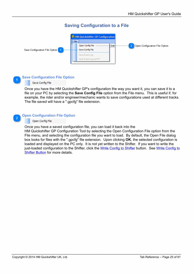
Save Configuration File Option
Once you have the HM Quickshifter GP's configuration the way you want it, you can save it to afile on your PC by selecting the Save Config File option from the File menu. This is useful if, forexample, the rider and/or engineer/mechanic wants to save configurations used at different tracks. The file saved will have a ".gpcfg" file extension.
Open Configuration File Option
Once you have a saved configuration file, you can load it back into theHM Quickshifter GP Configuration Tool by selecting the Open Configuration File option from theFile menu, and selecting the configuration file you want to load. By default, the Open File dialogbox looks for files with the ".gpcfg" file extension. Upon clicking OK, the selected configuration isloaded and displayed on the PC only. It is not yet written to the Shifter. If you want to write thejust-loaded configuration to the Shifter, click the Write Config to Shifter button. See Write Config toShifter Button for more details.
HM Quickshifter GP User's Guide
Overview Tab -- Page 26 of 81 Copyright © 2014 HM Quickshifter UK, Ltd.
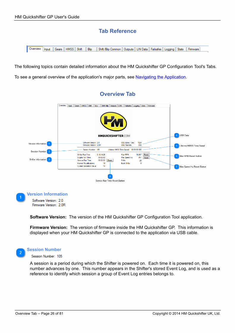
Tab Reference
The following topics contain detailed information about the HM Quickshifter GP Configuration Tool's Tabs. To see a general overview of the application's major parts, see Navigating the Application.
Overview Tab
Version Information
Software Version: The version of the HM Quickshifter GP Configuration Tool application. Firmware Version: The version of firmware inside the HM Quickshifter GP. This information isdisplayed when your HM Quickshifter GP is connected to the application via USB cable.
Session Number
A session is a period during which the Shifter is powered on. Each time it is powered on, thisnumber advances by one. This number appears in the Shifter's stored Event Log, and is used as areference to identify which session a group of Event Log entries belongs to.
HM Quickshifter GP User's Guide
Copyright © 2014 HM Quickshifter UK, Ltd. Overview Tab -- Page 27 of 81
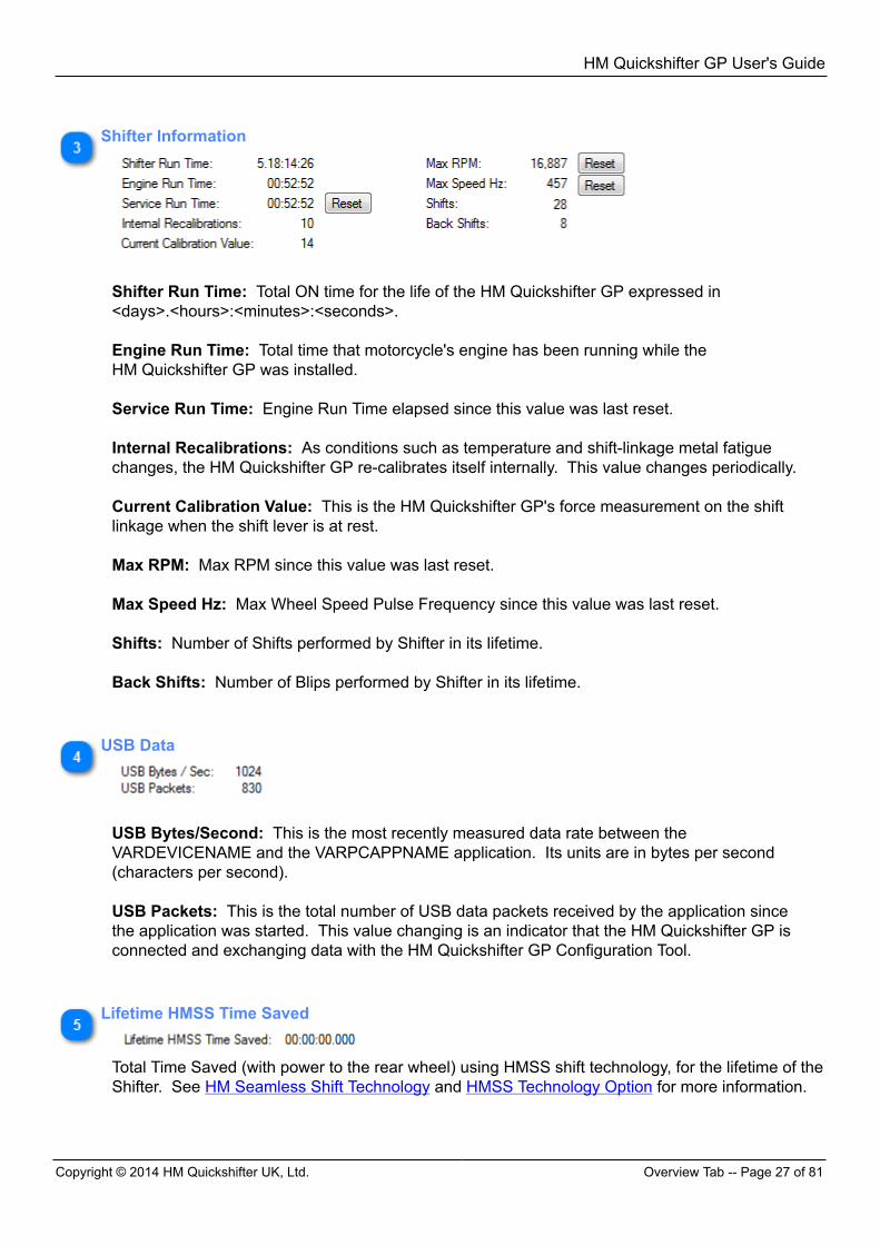
Shifter Information
Shifter Run Time: Total ON time for the life of the HM Quickshifter GP expressed in<days>.<hours>:<minutes>:<seconds>. Engine Run Time: Total time that motorcycle's engine has been running while theHM Quickshifter GP was installed. Service Run Time: Engine Run Time elapsed since this value was last reset. Internal Recalibrations: As conditions such as temperature and shift-linkage metal fatiguechanges, the HM Quickshifter GP re-calibrates itself internally. This value changes periodically. Current Calibration Value: This is the HM Quickshifter GP's force measurement on the shiftlinkage when the shift lever is at rest. Max RPM: Max RPM since this value was last reset. Max Speed Hz: Max Wheel Speed Pulse Frequency since this value was last reset. Shifts: Number of Shifts performed by Shifter in its lifetime. Back Shifts: Number of Blips performed by Shifter in its lifetime.
USB Data
USB Bytes/Second: This is the most recently measured data rate between theVARDEVICENAME and the VARPCAPPNAME application. Its units are in bytes per second(characters per second). USB Packets: This is the total number of USB data packets received by the application sincethe application was started. This value changing is an indicator that the HM Quickshifter GP isconnected and exchanging data with the HM Quickshifter GP Configuration Tool.
Lifetime HMSS Time Saved
Total Time Saved (with power to the rear wheel) using HMSS shift technology, for the lifetime of theShifter. See HM Seamless Shift Technology and HMSS Technology Option for more information.
HM Quickshifter GP User's Guide
Input Tab -- Page 28 of 81 Copyright © 2014 HM Quickshifter UK, Ltd.
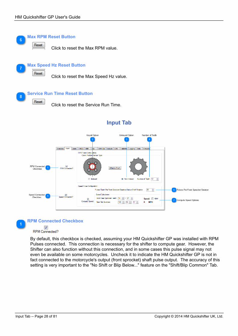
Max RPM Reset Button
Click to reset the Max RPM value.
Max Speed Hz Reset Button
Click to reset the Max Speed Hz value.
Service Run Time Reset Button
Click to reset the Service Run Time.
Input Tab
RPM Connected Checkbox
By default, this checkbox is checked, assuming your HM Quickshifter GP was installed with RPMPulses connected. This connection is necessary for the shifter to compute gear. However, theShifter can also function without this connection, and in some cases this pulse signal may noteven be available on some motorcycles. Uncheck it to indicate the HM Quickshifter GP is not infact connected to the motorcycle's output (front sprocket) shaft pulse output. The accuracy of thissetting is very important to the "No Shift or Blip Below..." feature on the "Shift/Blip Common" Tab.
HM Quickshifter GP User's Guide
Copyright © 2014 HM Quickshifter UK, Ltd. Input Tab -- Page 29 of 81
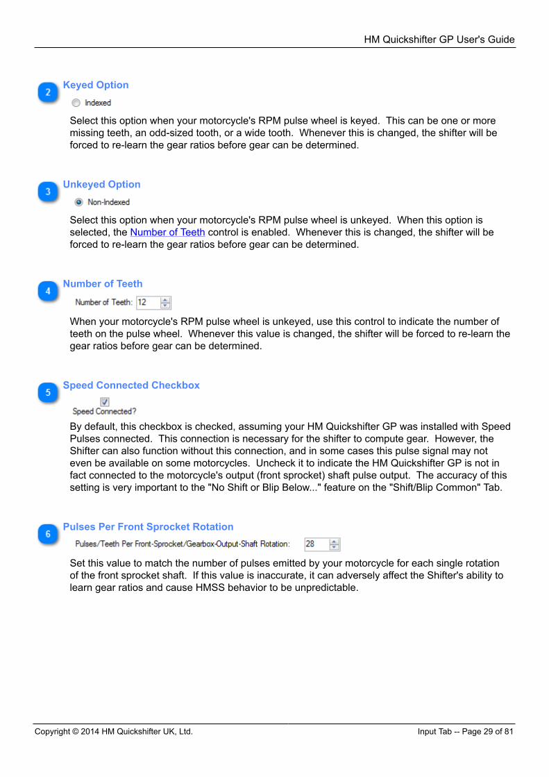
Keyed Option
Select this option when your motorcycle's RPM pulse wheel is keyed. This can be one or moremissing teeth, an odd-sized tooth, or a wide tooth. Whenever this is changed, the shifter will beforced to re-learn the gear ratios before gear can be determined.
Unkeyed Option
Select this option when your motorcycle's RPM pulse wheel is unkeyed. When this option isselected, the Number of Teeth control is enabled. Whenever this is changed, the shifter will beforced to re-learn the gear ratios before gear can be determined.
Number of Teeth
When your motorcycle's RPM pulse wheel is unkeyed, use this control to indicate the number ofteeth on the pulse wheel. Whenever this value is changed, the shifter will be forced to re-learn thegear ratios before gear can be determined.
Speed Connected Checkbox
By default, this checkbox is checked, assuming your HM Quickshifter GP was installed with SpeedPulses connected. This connection is necessary for the shifter to compute gear. However, theShifter can also function without this connection, and in some cases this pulse signal may noteven be available on some motorcycles. Uncheck it to indicate the HM Quickshifter GP is not infact connected to the motorcycle's output (front sprocket) shaft pulse output. The accuracy of thissetting is very important to the "No Shift or Blip Below..." feature on the "Shift/Blip Common" Tab.
Pulses Per Front Sprocket Rotation
Set this value to match the number of pulses emitted by your motorcycle for each single rotationof the front sprocket shaft. If this value is inaccurate, it can adversely affect the Shifter's ability tolearn gear ratios and cause HMSS behavior to be unpredictable.
HM Quickshifter GP User's Guide
Gears Tab -- Page 30 of 81 Copyright © 2014 HM Quickshifter UK, Ltd.
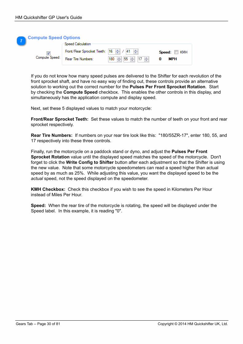
Compute Speed Options
If you do not know how many speed pulses are delivered to the Shifter for each revolution of thefront sprocket shaft, and have no easy way of finding out, these controls provide an alternativesolution to working out the correct number for the Pulses Per Front Sprocket Rotation. Startby checking the Compute Speed checkbox. This enables the other controls in this display, andsimultaneously has the application compute and display speed. Next, set these 5 displayed values to match your motorcycle: Front/Rear Sprocket Teeth: Set these values to match the number of teeth on your front and rearsprocket respectively. Rear Tire Numbers: If numbers on your rear tire look like this: "180/55ZR-17", enter 180, 55, and17 respectively into these three controls. Finally, run the motorcycle on a paddock stand or dyno, and adjust the Pulses Per FrontSprocket Rotation value until the displayed speed matches the speed of the motorcycle. Don'tforget to click the Write Config to Shifter button after each adjustment so that the Shifter is usingthe new value. Note that some motorcycle speedometers can read a speed higher than actualspeed by as much as 25%. While adjusting this value, you want the displayed speed to be theactual speed, not the speed displayed on the speedometer. KMH Checkbox: Check this checkbox if you wish to see the speed in Kilometers Per Hourinstead of Miles Per Hour. Speed: When the rear tire of the motorcycle is rotating, the speed will be displayed under theSpeed label. In this example, it is reading "0".
HM Quickshifter GP User's Guide
Copyright © 2014 HM Quickshifter UK, Ltd. Gears Tab -- Page 31 of 81
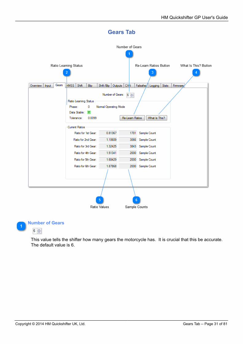
Gears Tab
Number of Gears
This value tells the shifter how many gears the motorcycle has. It is crucial that this be accurate. The default value is 6.
HM Quickshifter GP User's Guide
Gears Tab -- Page 32 of 81 Copyright © 2014 HM Quickshifter UK, Ltd.
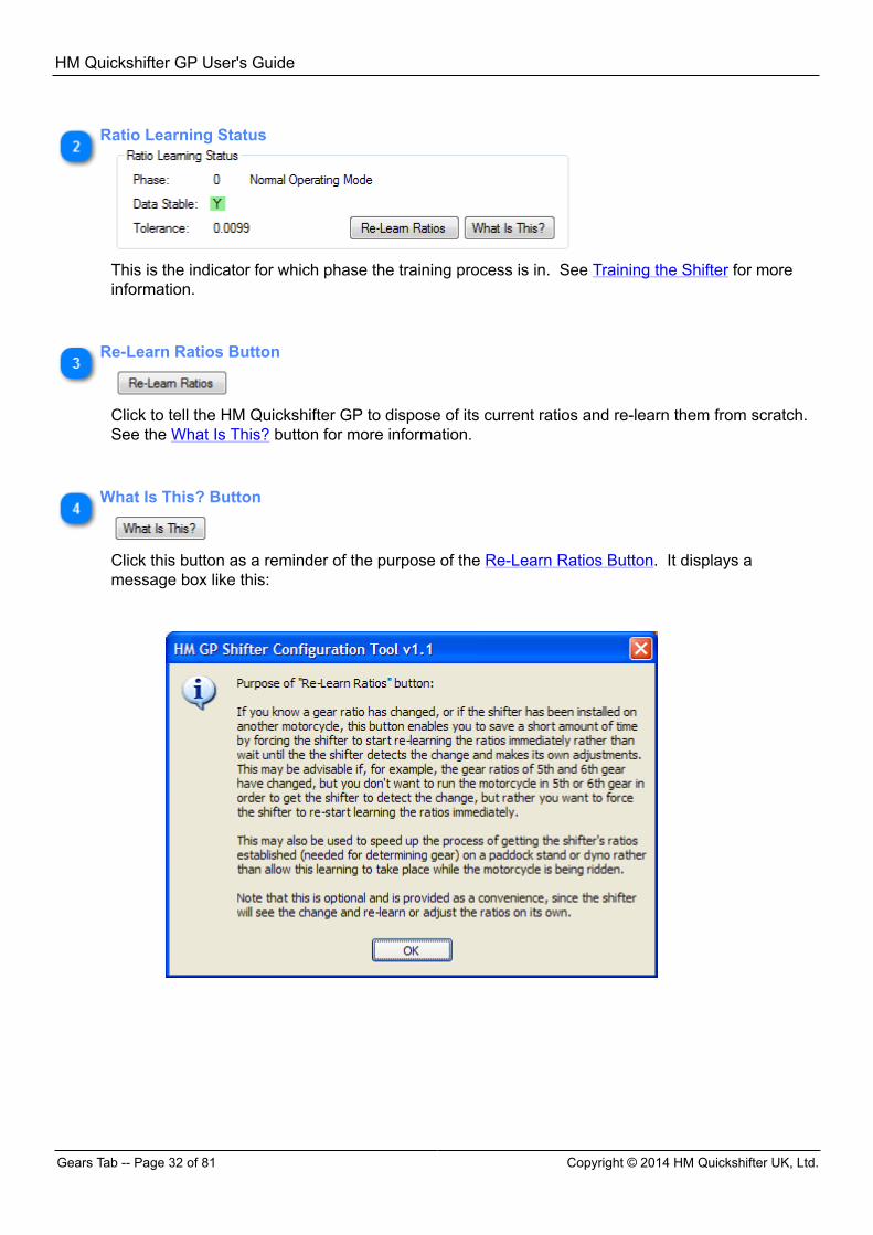
Ratio Learning Status
This is the indicator for which phase the training process is in. See Training the Shifter for moreinformation.
Re-Learn Ratios Button
Click to tell the HM Quickshifter GP to dispose of its current ratios and re-learn them from scratch. See the What Is This? button for more information.
What Is This? Button
Click this button as a reminder of the purpose of the Re-Learn Ratios Button. It displays amessage box like this:
HM Quickshifter GP User's Guide
Copyright © 2014 HM Quickshifter UK, Ltd. HMSS Tab -- Page 33 of 81
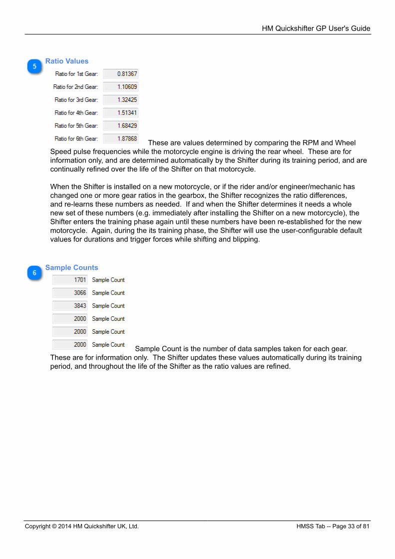
Ratio Values
These are values determined by comparing the RPM and WheelSpeed pulse frequencies while the motorcycle engine is driving the rear wheel. These are forinformation only, and are determined automatically by the Shifter during its training period, and arecontinually refined over the life of the Shifter on that motorcycle. When the Shifter is installed on a new motorcycle, or if the rider and/or engineer/mechanic haschanged one or more gear ratios in the gearbox, the Shifter recognizes the ratio differences,and re-learns these numbers as needed. If and when the Shifter determines it needs a wholenew set of these numbers (e.g. immediately after installing the Shifter on a new motorcycle), theShifter enters the training phase again until these numbers have been re-established for the newmotorcycle. Again, during the its training phase, the Shifter will use the user-configurable defaultvalues for durations and trigger forces while shifting and blipping.
Sample Counts
Sample Count is the number of data samples taken for each gear. These are for information only. The Shifter updates these values automatically during its trainingperiod, and throughout the life of the Shifter as the ratio values are refined.
HM Quickshifter GP User's Guide
HMSS Tab -- Page 34 of 81 Copyright © 2014 HM Quickshifter UK, Ltd.
HMSS Tab
HM Quickshifter GP User's Guide
Copyright © 2014 HM Quickshifter UK, Ltd. HMSS Tab -- Page 35 of 81
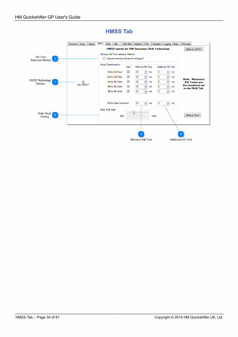
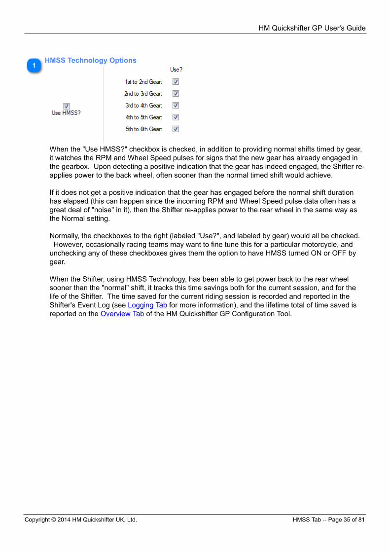
HMSS Technology Options
When the "Use HMSS?" checkbox is checked, in addition to providing normal shifts timed by gear,it watches the RPM and Wheel Speed pulses for signs that the new gear has already engaged inthe gearbox. Upon detecting a positive indication that the gear has indeed engaged, the Shifter re-applies power to the back wheel, often sooner than the normal timed shift would achieve. If it does not get a positive indication that the gear has engaged before the normal shift durationhas elapsed (this can happen since the incoming RPM and Wheel Speed pulse data often has agreat deal of "noise" in it), then the Shifter re-applies power to the rear wheel in the same way asthe Normal setting. Normally, the checkboxes to the right (labeled "Use?", and labeled by gear) would all be checked. However, occasionally racing teams may want to fine tune this for a particular motorcycle, andunchecking any of these checkboxes gives them the option to have HMSS turned ON or OFF bygear. When the Shifter, using HMSS Technology, has been able to get power back to the rear wheelsooner than the "normal" shift, it tracks this time savings both for the current session, and for thelife of the Shifter. The time saved for the current riding session is recorded and reported in theShifter's Event Log (see Logging Tab for more information), and the lifetime total of time saved isreported on the Overview Tab of the HM Quickshifter GP Configuration Tool.
HM Quickshifter GP User's Guide
HMSS Tab -- Page 36 of 81 Copyright © 2014 HM Quickshifter UK, Ltd.
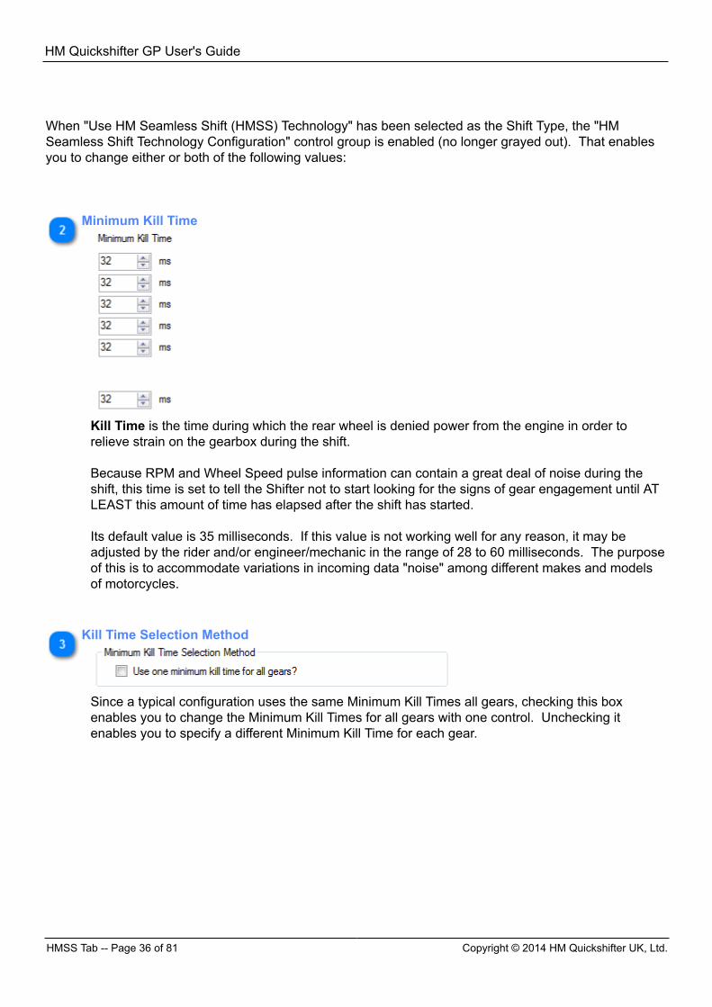
When "Use HM Seamless Shift (HMSS) Technology" has been selected as the Shift Type, the "HMSeamless Shift Technology Configuration" control group is enabled (no longer grayed out). That enablesyou to change either or both of the following values:
Minimum Kill Time
Kill Time is the time during which the rear wheel is denied power from the engine in order torelieve strain on the gearbox during the shift. Because RPM and Wheel Speed pulse information can contain a great deal of noise during theshift, this time is set to tell the Shifter not to start looking for the signs of gear engagement until ATLEAST this amount of time has elapsed after the shift has started. Its default value is 35 milliseconds. If this value is not working well for any reason, it may beadjusted by the rider and/or engineer/mechanic in the range of 28 to 60 milliseconds. The purposeof this is to accommodate variations in incoming data "noise" among different makes and modelsof motorcycles.
Kill Time Selection Method
Since a typical configuration uses the same Minimum Kill Times all gears, checking this boxenables you to change the Minimum Kill Times for all gears with one control. Unchecking itenables you to specify a different Minimum Kill Time for each gear.
HM Quickshifter GP User's Guide
Copyright © 2014 HM Quickshifter UK, Ltd. HMSS Tab -- Page 37 of 81
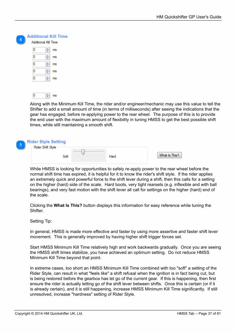
Additional Kill Time
Along with the Minimum Kill Time, the rider and/or engineer/mechanic may use this value to tell theShifter to add a small amount of time (in terms of milliseconds) after seeing the indications that thegear has engaged, before re-applying power to the rear wheel. The purpose of this is to providethe end user with the maximum amount of flexibility in tuning HMSS to get the best possible shifttimes, while still maintaining a smooth shift.
Rider Style Setting
While HMSS is looking for opportunities to safely re-apply power to the rear wheel before thenormal shift time has expired, it is helpful for it to know the rider's shift style. If the rider appliesan extremely quick and powerful force to the shift lever during a shift, then this calls for a settingon the higher (hard) side of the scale. Hard boots, very tight rearsets (e.g. inflexible and with ballbearings), and very fast motion with the shift lever all call for settings on the higher (hard) end ofthe scale. Clicking the What Is This? button displays this information for easy reference while tuning theShifter.
Setting Tip:
In general, HMSS is made more effective and faster by using more assertive and faster shift levermovement. This is generally improved by having higher shift trigger forces set.
Start HMSS Minimum Kill Time relatively high and work backwards gradually. Once you are seeingthe HMSS shift times stabilize, you have achieved an optimum setting. Do not reduce HMSSMinimum Kill Time beyond that point.
In extreme cases, too short an HMSS Minimum Kill Time combined with too "soft" a setting of theRider Style, can result in what "feels like" a shift refusal when the ignition is in fact being cut, butis being restored before the gearbox has let go of the current gear. If this is happening, then firstensure the rider is actually letting go of the shift lever between shifts. Once this is certain (or if itis already certain), and it is still happening, increase HMSS Minimum Kill Time significantly. If stillunresolved, increase "hardness" setting of Rider Style.

HM Quickshifter GP User's Guide
Shift -- Basic Settings Tab -- Page 38 of 81 Copyright © 2014 HM Quickshifter UK, Ltd.
HM Quickshifter GP User's Guide
Copyright © 2014 HM Quickshifter UK, Ltd. Shift -- Basic Settings Tab -- Page 39 of 81
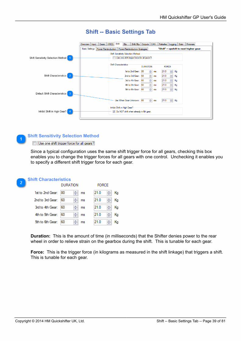
Shift -- Basic Settings Tab
Shift Sensitivity Selection Method
Since a typical configuration uses the same shift trigger force for all gears, checking this boxenables you to change the trigger forces for all gears with one control. Unchecking it enables youto specify a different shift trigger force for each gear.
Shift Characteristics
Duration: This is the amount of time (in milliseconds) that the Shifter denies power to the rearwheel in order to relieve strain on the gearbox during the shift. This is tunable for each gear. Force: This is the trigger force (in kilograms as measured in the shift linkage) that triggers a shift. This is tunable for each gear.
HM Quickshifter GP User's Guide
Shift -- Power Reintroduction Tab -- Page 40 of 81 Copyright © 2014 HM Quickshifter UK, Ltd.
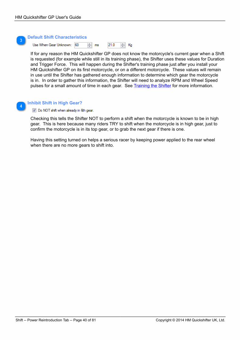
Default Shift Characteristics
If for any reason the HM Quickshifter GP does not know the motorcycle's current gear when a Shiftis requested (for example while still in its training phase), the Shifter uses these values for Durationand Trigger Force. This will happen during the Shifter's training phase just after you install yourHM Quickshifter GP on its first motorcycle, or on a different motorcycle. These values will remainin use until the Shifter has gathered enough information to determine which gear the motorcycleis in. In order to gather this information, the Shifter will need to analyze RPM and Wheel Speedpulses for a small amount of time in each gear. See Training the Shifter for more information.
Inhibit Shift in High Gear?
Checking this tells the Shifter NOT to perform a shift when the motorcycle is known to be in highgear. This is here because many riders TRY to shift when the motorcycle is in high gear, just toconfirm the motorcycle is in its top gear, or to grab the next gear if there is one. Having this setting turned on helps a serious racer by keeping power applied to the rear wheelwhen there are no more gears to shift into.
HM Quickshifter GP User's Guide
Copyright © 2014 HM Quickshifter UK, Ltd. Shift -- Power Reintroduction Tab -- Page 41 of 81
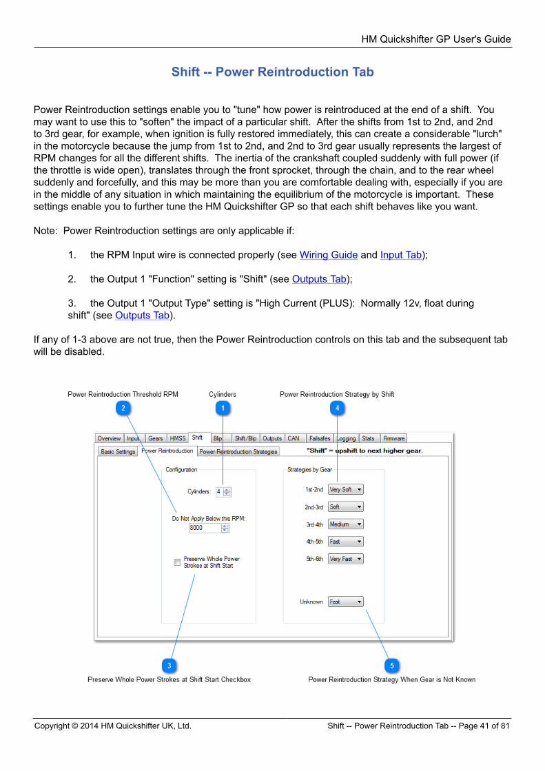
Shift -- Power Reintroduction Tab
Power Reintroduction settings enable you to "tune" how power is reintroduced at the end of a shift. Youmay want to use this to "soften" the impact of a particular shift. After the shifts from 1st to 2nd, and 2ndto 3rd gear, for example, when ignition is fully restored immediately, this can create a considerable "lurch"in the motorcycle because the jump from 1st to 2nd, and 2nd to 3rd gear usually represents the largest ofRPM changes for all the different shifts. The inertia of the crankshaft coupled suddenly with full power (ifthe throttle is wide open), translates through the front sprocket, through the chain, and to the rear wheelsuddenly and forcefully, and this may be more than you are comfortable dealing with, especially if you arein the middle of any situation in which maintaining the equilibrium of the motorcycle is important. Thesesettings enable you to further tune the HM Quickshifter GP so that each shift behaves like you want. Note: Power Reintroduction settings are only applicable if:
1. the RPM Input wire is connected properly (see Wiring Guide and Input Tab); 2. the Output 1 "Function" setting is "Shift" (see Outputs Tab); 3. the Output 1 "Output Type" setting is "High Current (PLUS): Normally 12v, float duringshift" (see Outputs Tab).
If any of 1-3 above are not true, then the Power Reintroduction controls on this tab and the subsequent tabwill be disabled.
HM Quickshifter GP User's Guide
Shift -- Power Reintroduction Tab -- Page 42 of 81 Copyright © 2014 HM Quickshifter UK, Ltd.
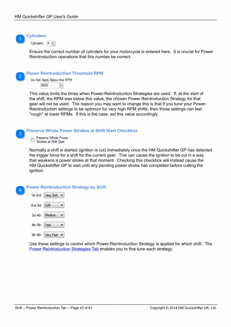
Cylinders
Ensure the correct number of cylinders for your motorcycle is entered here. It is crucial for PowerReintroduction operations that this number be correct.
Power Reintroduction Threshold RPM
This value limits the times when Power-Reintroduction Strategies are used. If, at the start ofthe shift, the RPM was below this value, the chosen Power Reintroduction Strategy for thatgear will not be used. The reason you may want to change this is that if you tune your Power-Reintroduction settings to be optimum for very high RPM shifts, then those settings can feel"rough" at lower RPMs. If this is the case, set this value accordingly.
Preserve Whole Power Strokes at Shift Start Checkbox
Normally a shift is started (ignition is cut) immediately once the HM Quickshifter GP has detectedthe trigger force for a shift for the current gear. This can cause the ignition to be cut in a waythat weakens a power stroke at that moment. Checking this checkbox will instead cause theHM Quickshifter GP to wait until any pending power stroke has completed before cutting theignition.
Power Reintroduction Strategy by Shift
Use these settings to control which Power-Reintroduction Strategy is applied for which shift. ThePower Reintroduction Strategies Tab enables you to fine tune each strategy.
HM Quickshifter GP User's Guide
Copyright © 2014 HM Quickshifter UK, Ltd. Shift -- Power Reintroduction Strategies Tab -- Page 43 of81
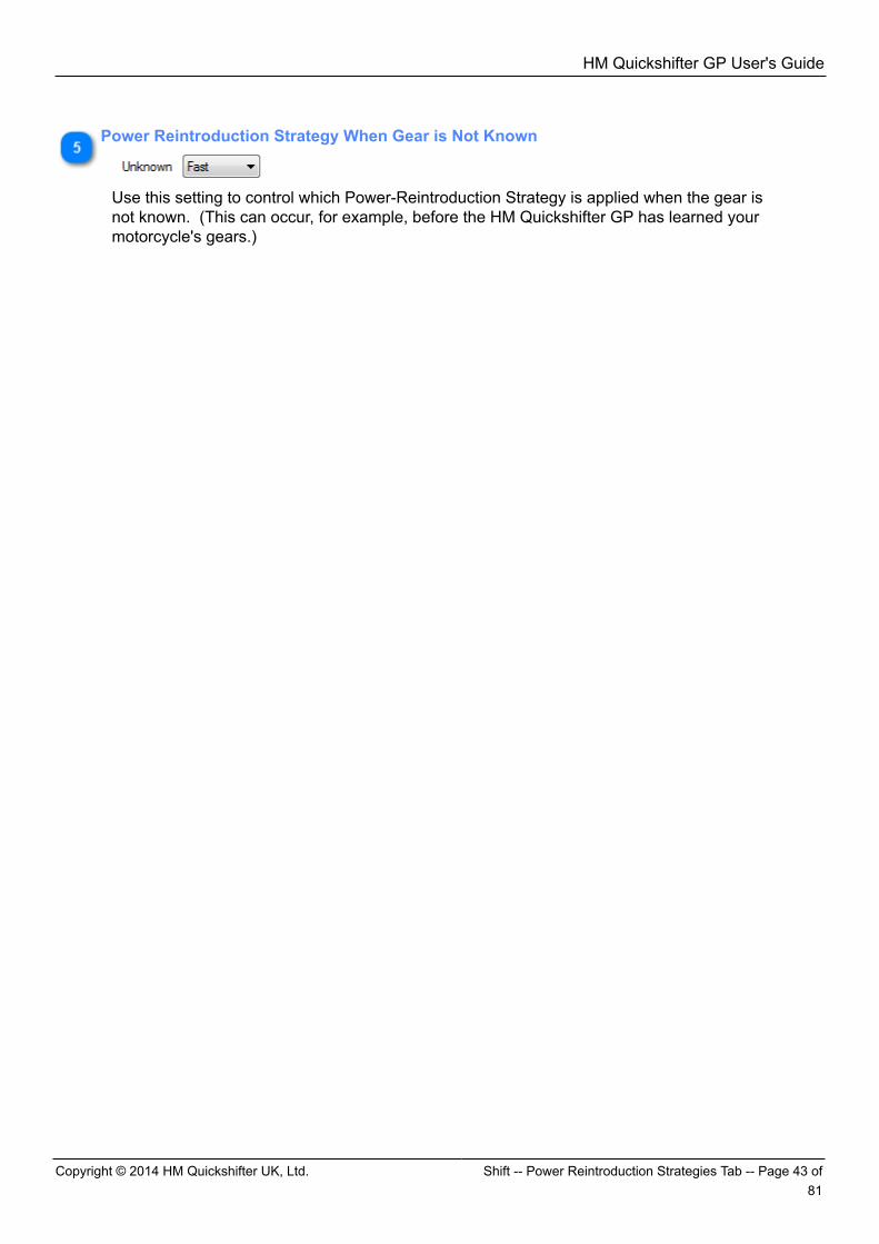
Power Reintroduction Strategy When Gear is Not Known
Use this setting to control which Power-Reintroduction Strategy is applied when the gear isnot known. (This can occur, for example, before the HM Quickshifter GP has learned yourmotorcycle's gears.)
HM Quickshifter GP User's Guide
Shift -- Power Reintroduction Strategies Tab -- Page 44 of 81 Copyright © 2014 HM Quickshifter UK, Ltd.
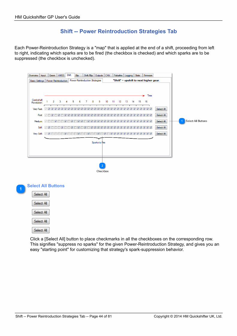
Shift -- Power Reintroduction Strategies Tab
Each Power-Reintroduction Strategy is a "map" that is applied at the end of a shift, proceeding from leftto right, indicating which sparks are to be fired (the checkbox is checked) and which sparks are to besuppressed (the checkbox is unchecked).
Select All Buttons
Click a [Select All] button to place checkmarks in all the checkboxes on the corresponding row. This signifies "suppress no sparks" for the given Power-Reintroduction Strategy, and gives you aneasy "starting point" for customizing that strategy's spark-suppression behavior.
HM Quickshifter GP User's Guide
Copyright © 2014 HM Quickshifter UK, Ltd. Blip Tab -- Page 45 of 81
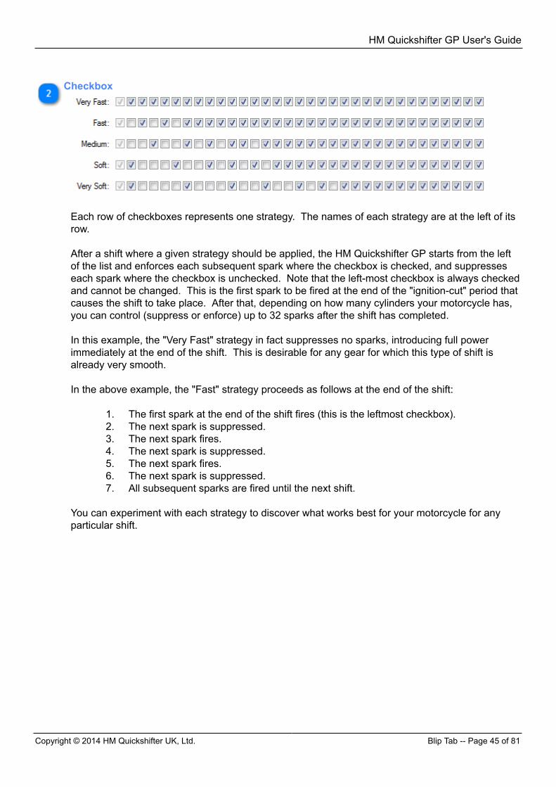
Checkbox
Each row of checkboxes represents one strategy. The names of each strategy are at the left of itsrow. After a shift where a given strategy should be applied, the HM Quickshifter GP starts from the leftof the list and enforces each subsequent spark where the checkbox is checked, and suppresseseach spark where the checkbox is unchecked. Note that the left-most checkbox is always checkedand cannot be changed. This is the first spark to be fired at the end of the "ignition-cut" period thatcauses the shift to take place. After that, depending on how many cylinders your motorcycle has,you can control (suppress or enforce) up to 32 sparks after the shift has completed. In this example, the "Very Fast" strategy in fact suppresses no sparks, introducing full powerimmediately at the end of the shift. This is desirable for any gear for which this type of shift isalready very smooth. In the above example, the "Fast" strategy proceeds as follows at the end of the shift:
1. The first spark at the end of the shift fires (this is the leftmost checkbox).2. The next spark is suppressed.3. The next spark fires.4. The next spark is suppressed.5. The next spark fires.6. The next spark is suppressed.7. All subsequent sparks are fired until the next shift.
You can experiment with each strategy to discover what works best for your motorcycle for anyparticular shift.
HM Quickshifter GP User's Guide
Blip Tab -- Page 46 of 81 Copyright © 2014 HM Quickshifter UK, Ltd.
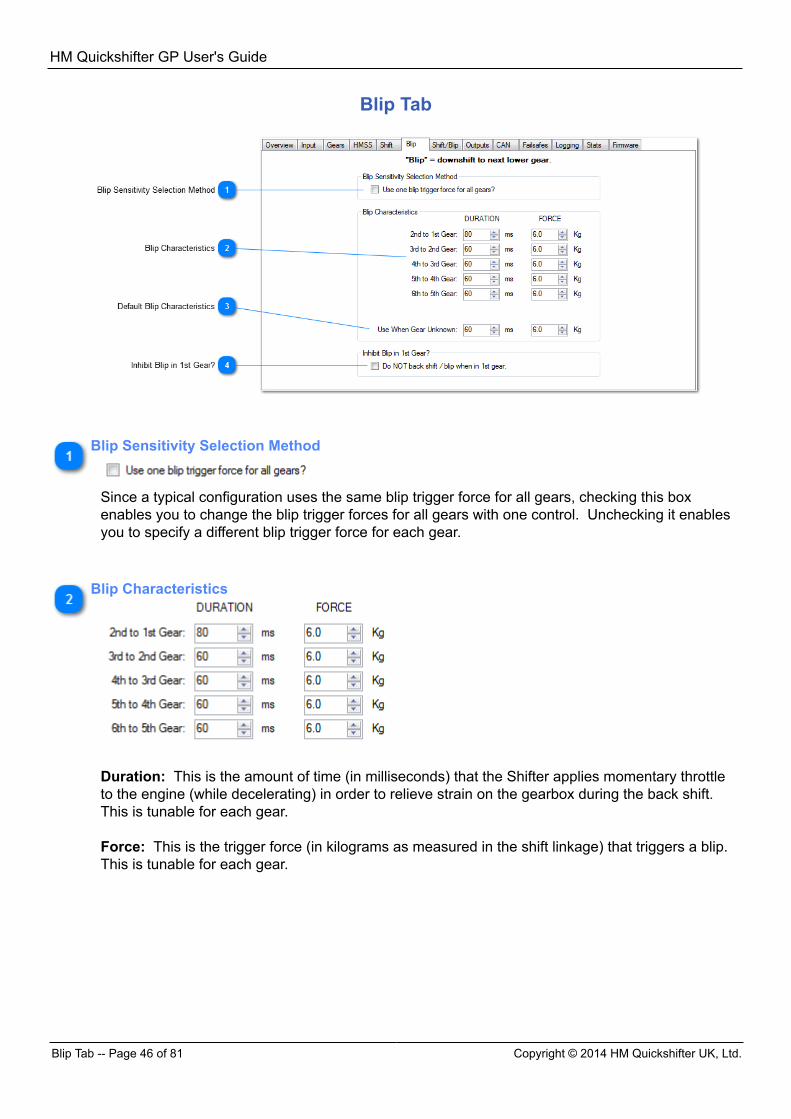
Blip Tab
Blip Sensitivity Selection Method
Since a typical configuration uses the same blip trigger force for all gears, checking this boxenables you to change the blip trigger forces for all gears with one control. Unchecking it enablesyou to specify a different blip trigger force for each gear.
Blip Characteristics
Duration: This is the amount of time (in milliseconds) that the Shifter applies momentary throttleto the engine (while decelerating) in order to relieve strain on the gearbox during the back shift. This is tunable for each gear. Force: This is the trigger force (in kilograms as measured in the shift linkage) that triggers a blip. This is tunable for each gear.
HM Quickshifter GP User's Guide
Copyright © 2014 HM Quickshifter UK, Ltd. Shift/Blip Common Tab -- Page 47 of 81
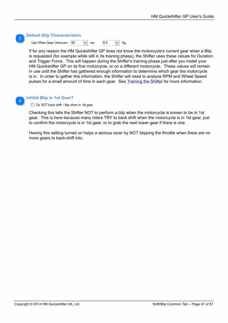
Default Blip Characteristics
If for any reason the HM Quickshifter GP does not know the motorcycle's current gear when a Blipis requested (for example while still in its training phase), the Shifter uses these values for Durationand Trigger Force. This will happen during the Shifter's training phase just after you install yourHM Quickshifter GP on its first motorcycle, or on a different motorcycle. These values will remainin use until the Shifter has gathered enough information to determine which gear the motorcycleis in. In order to gather this information, the Shifter will need to analyze RPM and Wheel Speedpulses for a small amount of time in each gear. See Training the Shifter for more information.
Inhibit Blip in 1st Gear?
Checking this tells the Shifter NOT to perform a blip when the motorcycle is known to be in 1stgear. This is here because many riders TRY to back shift when the motorcycle is in 1st gear, justto confirm the motorcycle is in 1st gear, or to grab the next lower gear if there is one. Having this setting turned on helps a serious racer by NOT blipping the throttle when there are nomore gears to back-shift into.
HM Quickshifter GP User's Guide
Shift/Blip Common Tab -- Page 48 of 81 Copyright © 2014 HM Quickshifter UK, Ltd.
Shift/Blip Common Tab
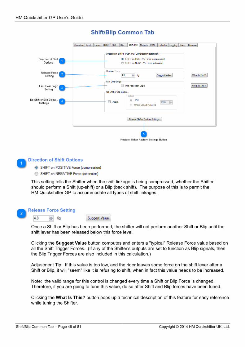
Direction of Shift Options
This setting tells the Shifter when the shift linkage is being compressed, whether the Shiftershould perform a Shift (up-shift) or a Blip (back shift). The purpose of this is to permit theHM Quickshifter GP to accommodate all types of shift linkages.
Release Force Setting
Once a Shift or Blip has been performed, the shifter will not perform another Shift or Blip until theshift lever has been released below this force level. Clicking the Suggest Value button computes and enters a "typical" Release Force value based onall the Shift Trigger Forces. (If any of the Shifter's outputs are set to function as Blip signals, thenthe Blip Trigger Forces are also included in this calculation.) Adjustment Tip: If this value is too low, and the rider leaves some force on the shift lever after aShift or Blip, it will "seem" like it is refusing to shift, when in fact this value needs to be increased. Note: the valid range for this control is changed every time a Shift or Blip Force is changed. Therefore, if you are going to tune this value, do so after Shift and Blip forces have been tuned. Clicking the What Is This? button pops up a technical description of this feature for easy referencewhile tuning the Shifter.
HM Quickshifter GP User's Guide
Copyright © 2014 HM Quickshifter UK, Ltd. Shift/Blip Common Tab -- Page 49 of 81
Fast Gear Logic Setting
The What Is This? button provides a quick reference as to the purpose and details of the FastGear Logic feature. If the HM Quickshifter GP's Output 2 is 1) set to CAN, 2) connected to external equipment, 3) setto communicate the current gear to that equipment, and 4) that equipment needs updated geardata IMMEDIATELY after a Shift or Blip (as opposed to after a very short period of time, after newRPM and SPEED pulse data have permitted confirmation of the new gear), then this feature canbe turned on to increase the immediacy with which the unconfirmed new gear data is transmitted tothe external equipment.
What the Fast Gear Logic does is increase or decrease the gear number internally at thecompletion of a Shift or Blip operation, BEFORE it has been confirmed by RPM and SPEED pulsesthat the gearbox actually changed gears. If the Shifter's Output 2 is set to transmit gear, and"Fast Gear Logic" is turned ON, this new gear data is automatically placed ahead of all other datawaiting to be transmitted. Under normal riding and shifting conditions, this information will becorrect most of the time. Precaution: note that at the precise moment after the Shift (ignition cut) or Blip operation has beenexecuted by the Shifter, the Shifter only knows that the Shift (ignition cut) or Blip operation hastaken place, but does not know with certainty whether the up-shift or down-shift in the gearboxactually took place yet. At this moment, it is only a high probability that it has, and has not beenconfirmed yet by RPM and SPEED pulses. If the rider does something unusual with the shiftlever, causing the Shifter to perform a Shift (ignition cut) or Blip operation, but the gearbox doesnot actually change gears, this information will be incorrect for a very short period, and will becorrected once the RPM and SPEED pulses have permitted the Shifter to confirm the gear. Thecorrected gear will be transmitted at that point. If "Fast Gear Logic" is ON, the gear data will beplaced ahead of all other data waiting to be transmitted. Clicking the What Is This? button pops up a technical description of this feature for easy referencewhile tuning the Shifter.
HM Quickshifter GP User's Guide
Outputs Tab -- Page 50 of 81 Copyright © 2014 HM Quickshifter UK, Ltd.
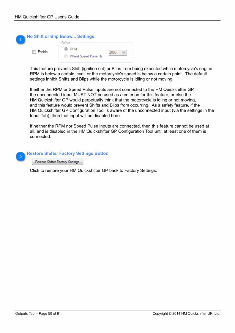
No Shift or Blip Below... Settings
This feature prevents Shift (ignition cut) or Blips from being executed while motorcycle's engineRPM is below a certain level, or the motorcycle's speed is below a certain point. The defaultsettings inhibit Shifts and Blips while the motorcycle is idling or not moving. If either the RPM or Speed Pulse inputs are not connected to the HM Quickshifter GP,the unconnected input MUST NOT be used as a criterion for this feature, or else theHM Quickshifter GP would perpetually think that the motorcycle is idling or not moving,and this feature would prevent Shifts and Blips from occurring. As a safety feature, if theHM Quickshifter GP Configuration Tool is aware of the unconnected input (via the settings in theInput Tab), then that input will be disabled here. If neither the RPM nor Speed Pulse inputs are connected, then this feature cannot be used atall, and is disabled in the HM Quickshifter GP Configuration Tool until at least one of them isconnected.
Restore Shifter Factory Settings Button
Click to restore your HM Quickshifter GP back to Factory Settings.
HM Quickshifter GP User's Guide
Copyright © 2014 HM Quickshifter UK, Ltd. Outputs Tab -- Page 51 of 81
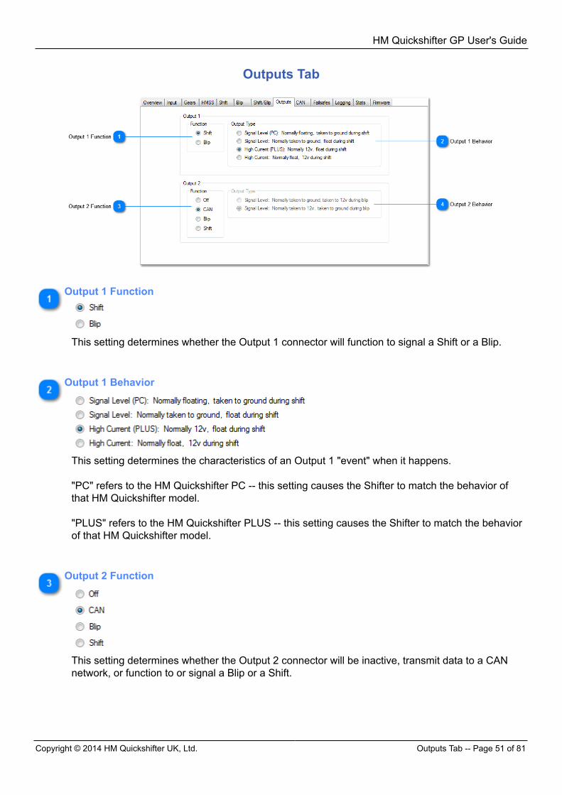
Outputs Tab
Output 1 Function
This setting determines whether the Output 1 connector will function to signal a Shift or a Blip.
Output 1 Behavior
This setting determines the characteristics of an Output 1 "event" when it happens. "PC" refers to the HM Quickshifter PC -- this setting causes the Shifter to match the behavior ofthat HM Quickshifter model. "PLUS" refers to the HM Quickshifter PLUS -- this setting causes the Shifter to match the behaviorof that HM Quickshifter model.
Output 2 Function
This setting determines whether the Output 2 connector will be inactive, transmit data to a CANnetwork, or function to or signal a Blip or a Shift.
HM Quickshifter GP User's Guide
CAN Tab -- Page 52 of 81 Copyright © 2014 HM Quickshifter UK, Ltd.
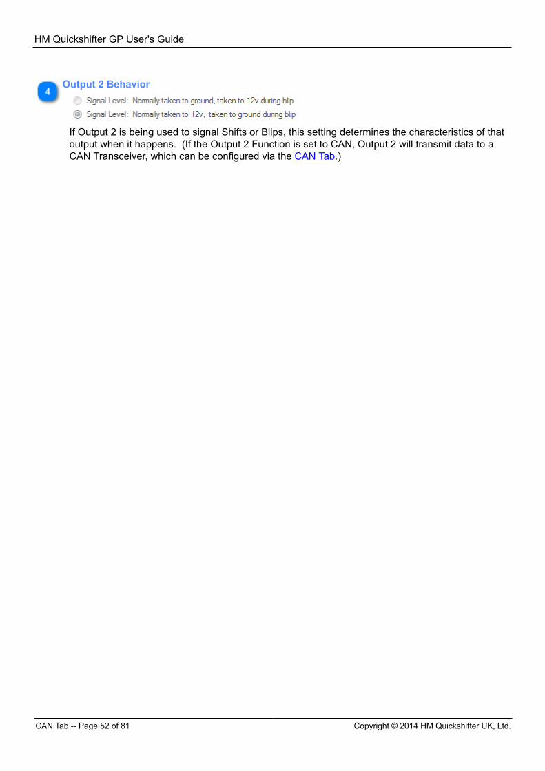
Output 2 Behavior
If Output 2 is being used to signal Shifts or Blips, this setting determines the characteristics of thatoutput when it happens. (If the Output 2 Function is set to CAN, Output 2 will transmit data to aCAN Transceiver, which can be configured via the CAN Tab.)
HM Quickshifter GP User's Guide
Copyright © 2014 HM Quickshifter UK, Ltd. CAN Tab -- Page 53 of 81
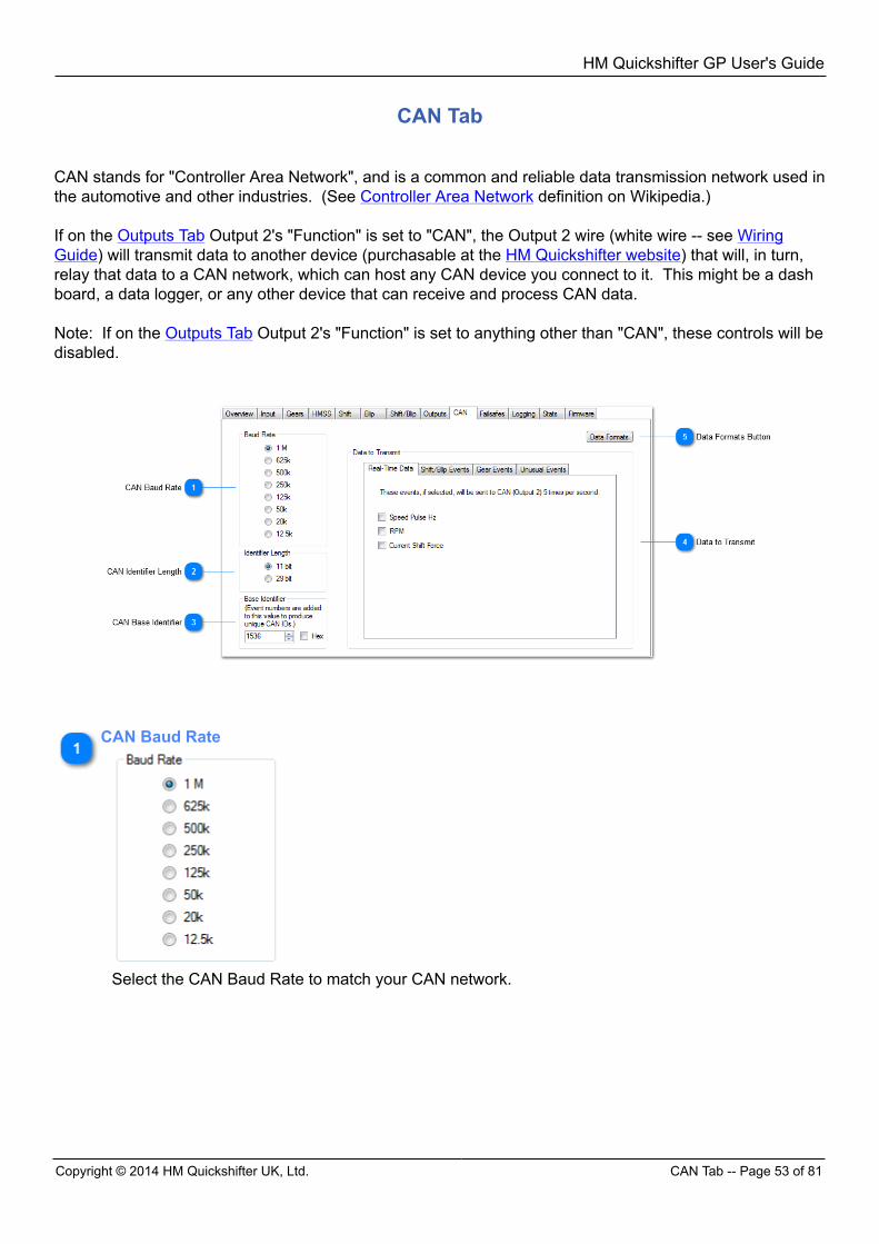
CAN Tab
CAN stands for "Controller Area Network", and is a common and reliable data transmission network used inthe automotive and other industries. (See Controller Area Network definition on Wikipedia.) If on the Outputs Tab Output 2's "Function" is set to "CAN", the Output 2 wire (white wire -- see WiringGuide) will transmit data to another device (purchasable at the HM Quickshifter website) that will, in turn,relay that data to a CAN network, which can host any CAN device you connect to it. This might be a dashboard, a data logger, or any other device that can receive and process CAN data. Note: If on the Outputs Tab Output 2's "Function" is set to anything other than "CAN", these controls will bedisabled.
CAN Baud Rate
Select the CAN Baud Rate to match your CAN network.
HM Quickshifter GP User's Guide
CAN Tab -- Page 54 of 81 Copyright © 2014 HM Quickshifter UK, Ltd.
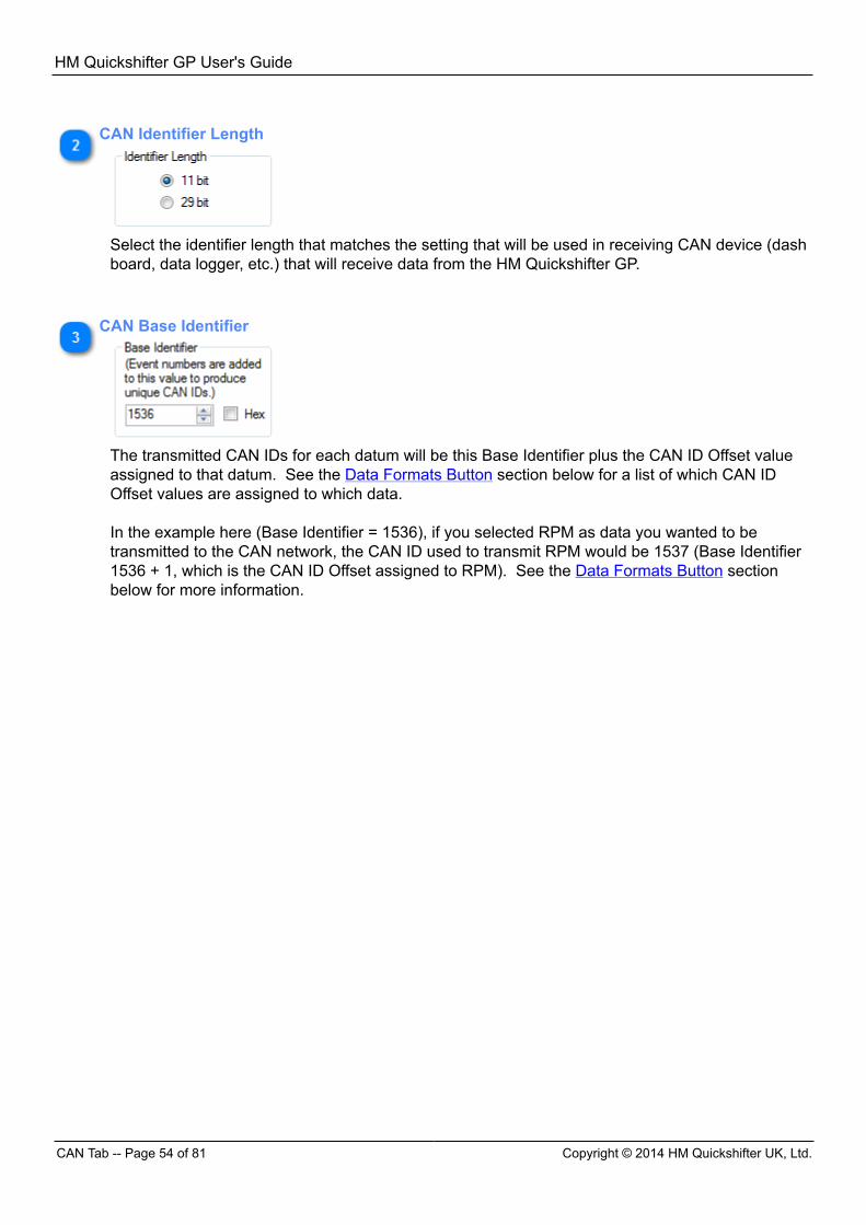
CAN Identifier Length
Select the identifier length that matches the setting that will be used in receiving CAN device (dashboard, data logger, etc.) that will receive data from the HM Quickshifter GP.
CAN Base Identifier
The transmitted CAN IDs for each datum will be this Base Identifier plus the CAN ID Offset valueassigned to that datum. See the Data Formats Button section below for a list of which CAN IDOffset values are assigned to which data. In the example here (Base Identifier = 1536), if you selected RPM as data you wanted to betransmitted to the CAN network, the CAN ID used to transmit RPM would be 1537 (Base Identifier1536 + 1, which is the CAN ID Offset assigned to RPM). See the Data Formats Button sectionbelow for more information.
HM Quickshifter GP User's Guide
Copyright © 2014 HM Quickshifter UK, Ltd. CAN Tab -- Page 55 of 81
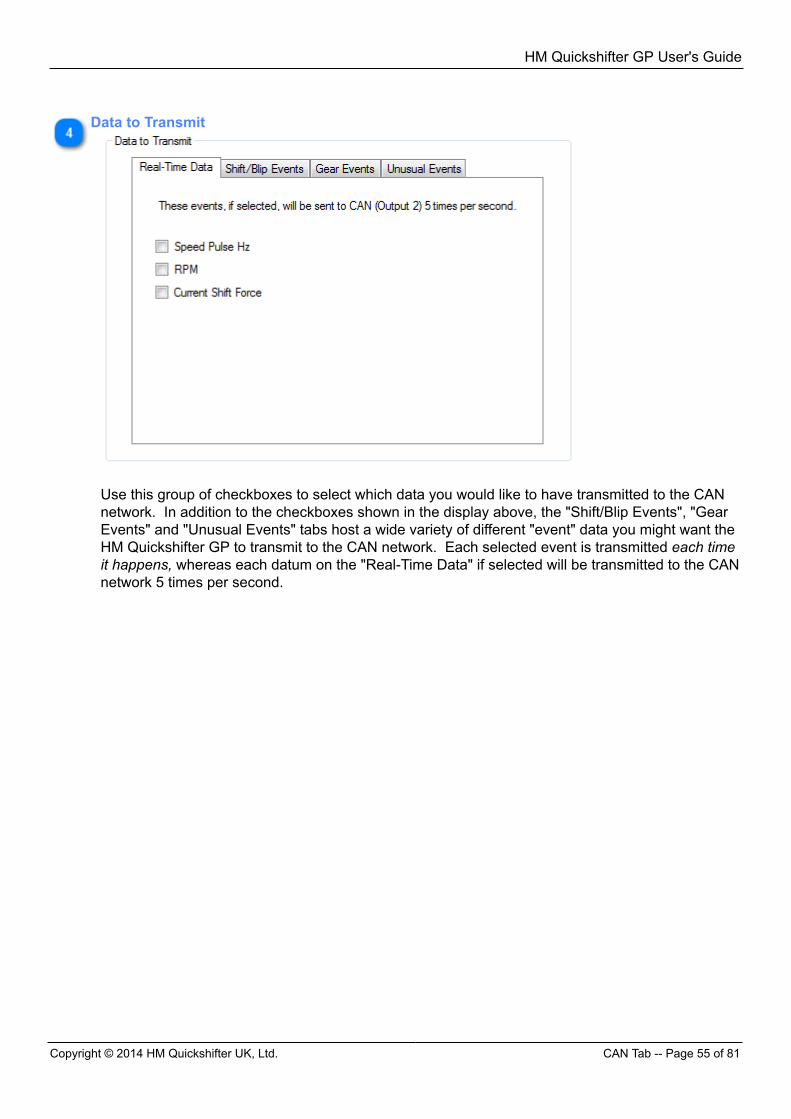
Data to Transmit
Use this group of checkboxes to select which data you would like to have transmitted to the CANnetwork. In addition to the checkboxes shown in the display above, the "Shift/Blip Events", "GearEvents" and "Unusual Events" tabs host a wide variety of different "event" data you might want theHM Quickshifter GP to transmit to the CAN network. Each selected event is transmitted each timeit happens, whereas each datum on the "Real-Time Data" if selected will be transmitted to the CANnetwork 5 times per second.
HM Quickshifter GP User's Guide
CAN Tab -- Page 56 of 81 Copyright © 2014 HM Quickshifter UK, Ltd.
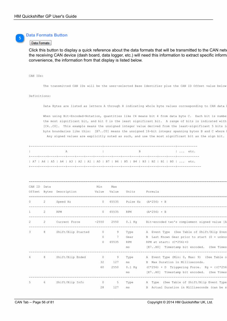
Data Formats Button
Click this button to display a quick reference about the data formats that will be transmitted to the CAN network. The person who configuresthe receiving CAN device (dash board, data logger, etc.) will need this information to extract specific information from the CAN data. Forconvenience, the information from that display is listed below. CAN IDs:
The transmitted CAN IDs will be the user-selected Base Identifier plus the CAN ID Offset value below.
Definitions:
Data Bytes are listed as letters A through H indicating whole byte values corresponding to CAN data bytes 1 through 8 respectively.
When using Bit-Encoded-Notation, quantities like C4 means bit 4 from data byte C. Each bit is numbered from 0 to 7, so bit 7 is
the most significant bit, and bit 0 is the least significant bit. A range of bits is indicated with square brackets like this:
[C4..C0]. This example means the unsigned integer value derived from the least-significant 5 bits in byte C. Bit ranges can cross
byte boundaries like this: [B7..C0] means the unsigned 16-bit integer spanning bytes B and C where bit B7 is the most significant bit.
Any signed values are explicitly noted as such, and use the most significant bit as the sign bit.
+---------------------------------------+---------------------------------------+-----------
| A | B | ... etc.
+----+----+----+----+----+----+----+----+----+----+----+----+----+----+----+----+------------
| A7 | A6 | A5 | A4 | A3 | A2 | A1 | A0 | B7 | B6 | B5 | B4 | B3 | B2 | B1 | B0 | ... etc.
+----+----+----+----+----+----+----+----+----+----+----+----+----+----+----+----+-------------
=============================================================================================================================================
CAN ID Data Min Max
Offset Bytes Description Value Value Units Formula
=============================================================================================================================================
0 2 Speed Hz 0 65535 Pulse Hz (A*256) + B
---------------------------------------------------------------------------------------------------------------------------------------------
1 2 RPM 0 65535 RPM (A*256) + B
---------------------------------------------------------------------------------------------------------------------------------------------
2 2 Current Force -2550 2550 0.1 Kg Bit-encoded two's complement signed value [A7..B0] where A7 is sign bit.
---------------------------------------------------------------------------------------------------------------------------------------------
3 8 Shift/Blip Started 0 9 Type A Event Type (See Table of Shift/Blip Event Types below.)
0 7 Gear B Last Known Gear prior to start (0 = unknown)
0 65535 RPM RPM at start: (C*256)+D
ms [E7..H0] Timestamp bit encoded. (See Timestamp definition below.)
---------------------------------------------------------------------------------------------------------------------------------------------
4 8 Shift/Blip Ended 0 9 Type A Event Type (Min: 0, Max: 9) (See Table of Shift/Blip Event Types below.)
32 127 ms B Max Duration in Milliseconds.
60 2550 0.1 Kg (C*256) + D Triggering Force. Kg = ((C*256)+D) * 10.
ms [E7..H0] Timestamp bit encoded. (See Timestamp definition below.)
---------------------------------------------------------------------------------------------------------------------------------------------
5 6 Shift/Blip Info 0 5 Type A Type (See Table of Shift/Blip Event Types below.)
28 127 ms B Actual Duration in Milliseconds (can be shorter than max duration).
HM Quickshifter GP User's Guide
Copyright © 2014 HM Quickshifter UK, Ltd. CAN Tab -- Page 57 of 81
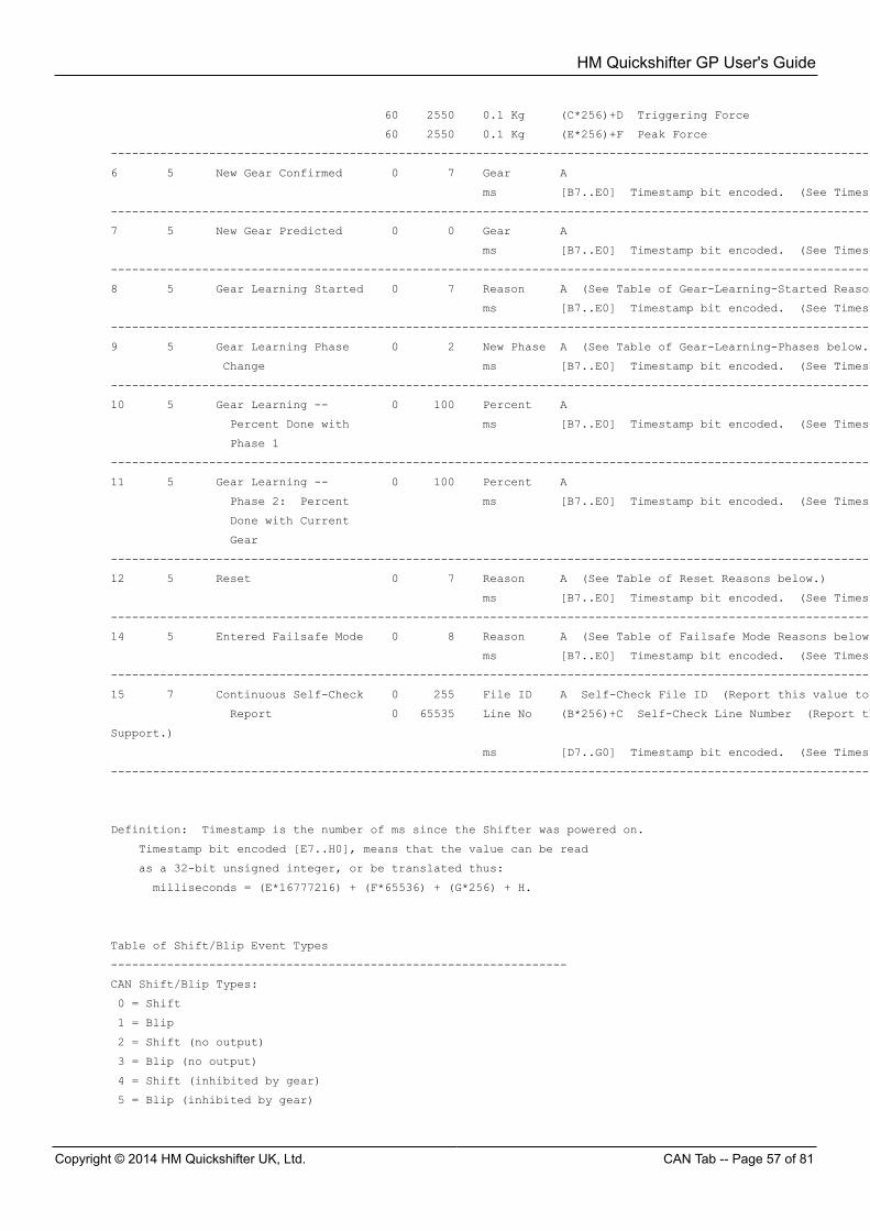
60 2550 0.1 Kg (C*256)+D Triggering Force
60 2550 0.1 Kg (E*256)+F Peak Force
---------------------------------------------------------------------------------------------------------------------------------------------
6 5 New Gear Confirmed 0 7 Gear A
ms [B7..E0] Timestamp bit encoded. (See Timestamp definition below.)
---------------------------------------------------------------------------------------------------------------------------------------------
7 5 New Gear Predicted 0 0 Gear A
ms [B7..E0] Timestamp bit encoded. (See Timestamp definition below.)
---------------------------------------------------------------------------------------------------------------------------------------------
8 5 Gear Learning Started 0 7 Reason A (See Table of Gear-Learning-Started Reasons below.)
ms [B7..E0] Timestamp bit encoded. (See Timestamp definition below.)
---------------------------------------------------------------------------------------------------------------------------------------------
9 5 Gear Learning Phase 0 2 New Phase A (See Table of Gear-Learning-Phases below.)
Change ms [B7..E0] Timestamp bit encoded. (See Timestamp definition below.)
---------------------------------------------------------------------------------------------------------------------------------------------
10 5 Gear Learning -- 0 100 Percent A
Percent Done with ms [B7..E0] Timestamp bit encoded. (See Timestamp definition below.)
Phase 1
---------------------------------------------------------------------------------------------------------------------------------------------
11 5 Gear Learning -- 0 100 Percent A
Phase 2: Percent ms [B7..E0] Timestamp bit encoded. (See Timestamp definition below.)
Done with Current
Gear
---------------------------------------------------------------------------------------------------------------------------------------------
12 5 Reset 0 7 Reason A (See Table of Reset Reasons below.)
ms [B7..E0] Timestamp bit encoded. (See Timestamp definition below.)
---------------------------------------------------------------------------------------------------------------------------------------------
14 5 Entered Failsafe Mode 0 8 Reason A (See Table of Failsafe Mode Reasons below.)
ms [B7..E0] Timestamp bit encoded. (See Timestamp definition below.)
---------------------------------------------------------------------------------------------------------------------------------------------
15 7 Continuous Self-Check 0 255 File ID A Self-Check File ID (Report this value to HM Quickshifter Tech Support.)
Report 0 65535 Line No (B*256)+C Self-Check Line Number (Report this value to HM Quickshifter Tech
Support.)
ms [D7..G0] Timestamp bit encoded. (See Timestamp definition below.)
---------------------------------------------------------------------------------------------------------------------------------------------
Definition: Timestamp is the number of ms since the Shifter was powered on.
Timestamp bit encoded [E7..H0], means that the value can be read
as a 32-bit unsigned integer, or be translated thus:
milliseconds = (E*16777216) + (F*65536) + (G*256) + H.
Table of Shift/Blip Event Types
-----------------------------------------------------------------
CAN Shift/Blip Types:
0 = Shift
1 = Blip
2 = Shift (no output)
3 = Blip (no output)
4 = Shift (inhibited by gear)
5 = Blip (inhibited by gear)
HM Quickshifter GP User's Guide
CAN Tab -- Page 58 of 81 Copyright © 2014 HM Quickshifter UK, Ltd.
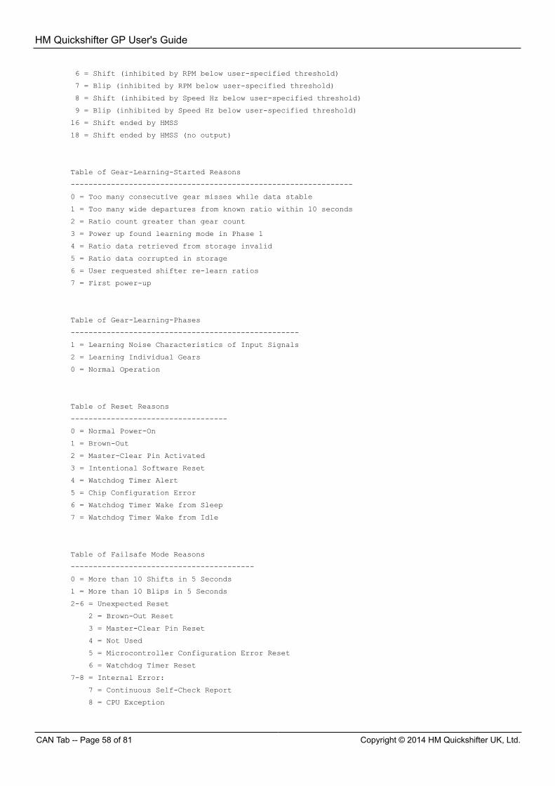
6 = Shift (inhibited by RPM below user-specified threshold)
7 = Blip (inhibited by RPM below user-specified threshold)
8 = Shift (inhibited by Speed Hz below user-specified threshold)
9 = Blip (inhibited by Speed Hz below user-specified threshold)
16 = Shift ended by HMSS
18 = Shift ended by HMSS (no output)
Table of Gear-Learning-Started Reasons
---------------------------------------------------------------
0 = Too many consecutive gear misses while data stable
1 = Too many wide departures from known ratio within 10 seconds
2 = Ratio count greater than gear count
3 = Power up found learning mode in Phase 1
4 = Ratio data retrieved from storage invalid
5 = Ratio data corrupted in storage
6 = User requested shifter re-learn ratios
7 = First power-up
Table of Gear-Learning-Phases
---------------------------------------------------
1 = Learning Noise Characteristics of Input Signals
2 = Learning Individual Gears
0 = Normal Operation
Table of Reset Reasons
-----------------------------------
0 = Normal Power-On
1 = Brown-Out
2 = Master-Clear Pin Activated
3 = Intentional Software Reset
4 = Watchdog Timer Alert
5 = Chip Configuration Error
6 = Watchdog Timer Wake from Sleep
7 = Watchdog Timer Wake from Idle
Table of Failsafe Mode Reasons
-----------------------------------------
0 = More than 10 Shifts in 5 Seconds
1 = More than 10 Blips in 5 Seconds
2-6 = Unexpected Reset
2 = Brown-Out Reset
3 = Master-Clear Pin Reset
4 = Not Used
5 = Microcontroller Configuration Error Reset
6 = Watchdog Timer Reset
7-8 = Internal Error:
7 = Continuous Self-Check Report
8 = CPU Exception

HM Quickshifter GP User's Guide
Copyright © 2014 HM Quickshifter UK, Ltd. Failsafes Tab -- Page 59 of 81
HM Quickshifter GP User's Guide
Failsafes Tab -- Page 60 of 81 Copyright © 2014 HM Quickshifter UK, Ltd.
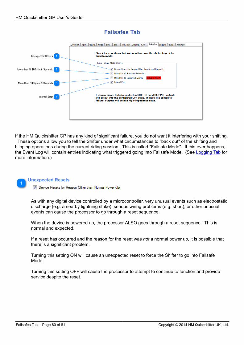
Failsafes Tab
If the HM Quickshifter GP has any kind of significant failure, you do not want it interfering with your shifting. These options allow you to tell the Shifter under what circumstances to "back out" of the shifting andblipping operations during the current riding session. This is called "Failsafe Mode". If this ever happens,the Event Log will contain entries indicating what triggered going into Failsafe Mode. (See Logging Tab formore information.)
Unexpected Resets
As with any digital device controlled by a microcontroller, very unusual events such as electrostaticdischarge (e.g. a nearby lightning strike), serious wiring problems (e.g. short), or other unusualevents can cause the processor to go through a reset sequence. When the device is powered up, the processor ALSO goes through a reset sequence. This isnormal and expected. If a reset has occurred and the reason for the reset was not a normal power up, it is possible thatthere is a significant problem. Turning this setting ON will cause an unexpected reset to force the Shifter to go into FailsafeMode. Turning this setting OFF will cause the processor to attempt to continue to function and provideservice despite the reset.
HM Quickshifter GP User's Guide
Copyright © 2014 HM Quickshifter UK, Ltd. Failsafes Tab -- Page 61 of 81
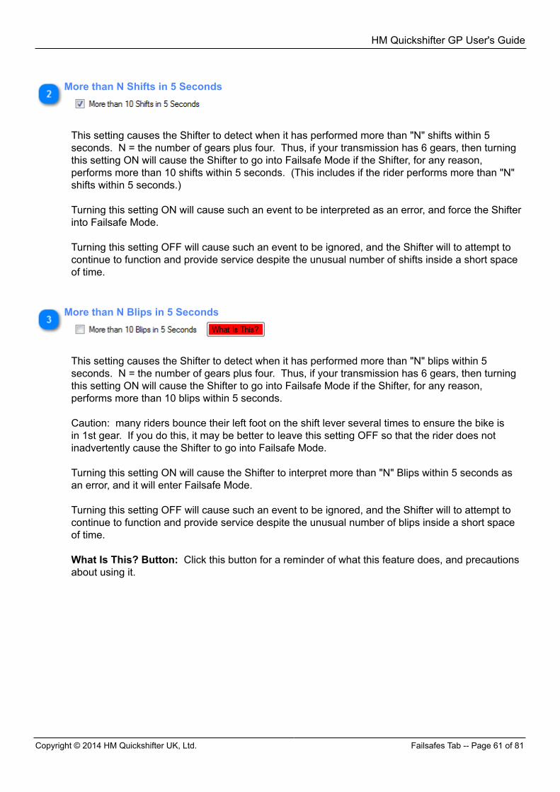
More than N Shifts in 5 Seconds
This setting causes the Shifter to detect when it has performed more than "N" shifts within 5seconds. N = the number of gears plus four. Thus, if your transmission has 6 gears, then turningthis setting ON will cause the Shifter to go into Failsafe Mode if the Shifter, for any reason,performs more than 10 shifts within 5 seconds. (This includes if the rider performs more than "N"shifts within 5 seconds.) Turning this setting ON will cause such an event to be interpreted as an error, and force the Shifterinto Failsafe Mode. Turning this setting OFF will cause such an event to be ignored, and the Shifter will to attempt tocontinue to function and provide service despite the unusual number of shifts inside a short spaceof time.
More than N Blips in 5 Seconds
This setting causes the Shifter to detect when it has performed more than "N" blips within 5seconds. N = the number of gears plus four. Thus, if your transmission has 6 gears, then turningthis setting ON will cause the Shifter to go into Failsafe Mode if the Shifter, for any reason,performs more than 10 blips within 5 seconds. Caution: many riders bounce their left foot on the shift lever several times to ensure the bike isin 1st gear. If you do this, it may be better to leave this setting OFF so that the rider does notinadvertently cause the Shifter to go into Failsafe Mode. Turning this setting ON will cause the Shifter to interpret more than "N" Blips within 5 seconds asan error, and it will enter Failsafe Mode. Turning this setting OFF will cause such an event to be ignored, and the Shifter will to attempt tocontinue to function and provide service despite the unusual number of blips inside a short spaceof time. What Is This? Button: Click this button for a reminder of what this feature does, and precautionsabout using it.
HM Quickshifter GP User's Guide
Logging Tab -- Page 62 of 81 Copyright © 2014 HM Quickshifter UK, Ltd.
Internal Error
A large number of internal self-checks are in full-time operation within the Shifter. If oneof these detects something is not as it should be, then an internal error is deemed to haveoccurred, and further information about it is logged in the Shifter's Event Log (translatable byHM Quickshifter UK, Ltd. Tech Support staff). Turning this setting ON will cause the Shifter to go into Failsafe Mode if any such event occurs. Turning this setting OFF will cause such an event to be ignored, and the Shifter will to attempt tocontinue to function and provide service despite the internal error.
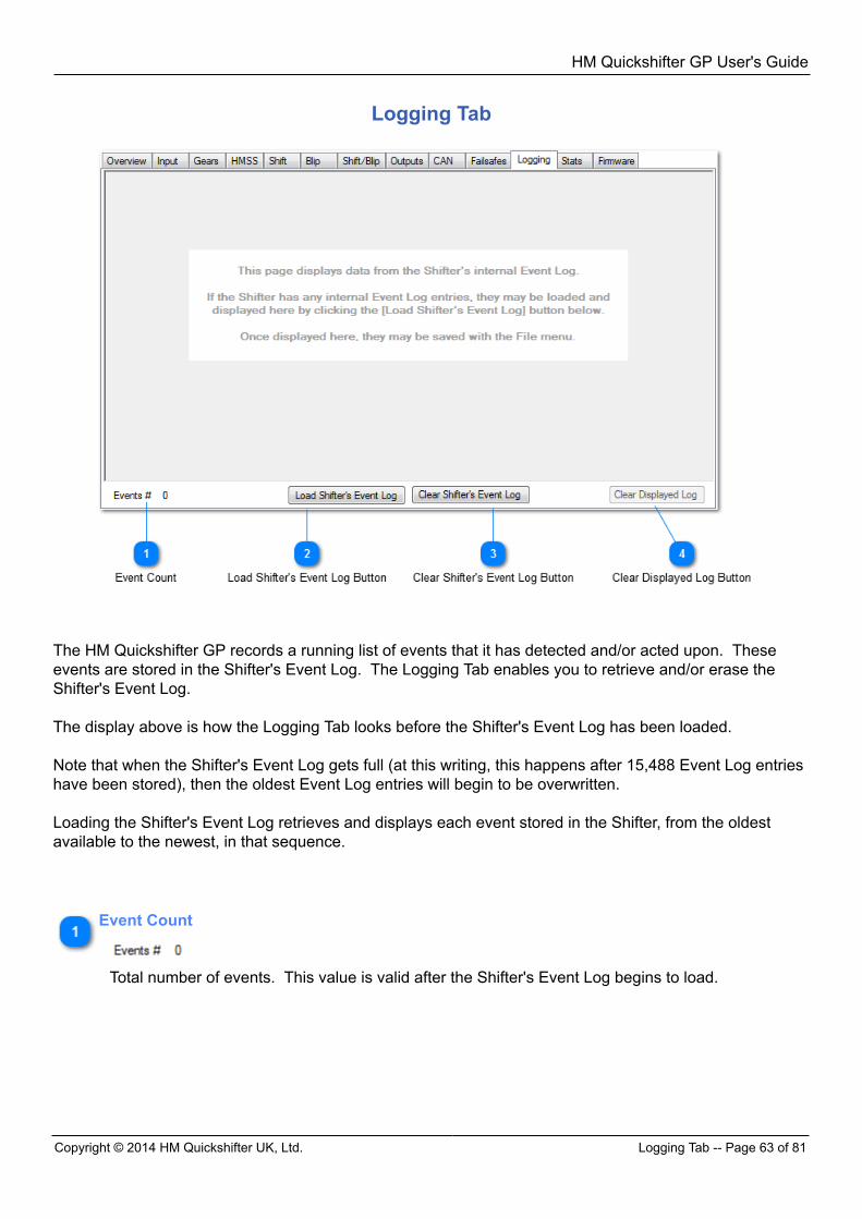
HM Quickshifter GP User's Guide
Copyright © 2014 HM Quickshifter UK, Ltd. Logging Tab -- Page 63 of 81
Logging Tab
The HM Quickshifter GP records a running list of events that it has detected and/or acted upon. Theseevents are stored in the Shifter's Event Log. The Logging Tab enables you to retrieve and/or erase theShifter's Event Log. The display above is how the Logging Tab looks before the Shifter's Event Log has been loaded. Note that when the Shifter's Event Log gets full (at this writing, this happens after 15,488 Event Log entrieshave been stored), then the oldest Event Log entries will begin to be overwritten. Loading the Shifter's Event Log retrieves and displays each event stored in the Shifter, from the oldestavailable to the newest, in that sequence.
Event Count
Total number of events. This value is valid after the Shifter's Event Log begins to load.
HM Quickshifter GP User's Guide
After Event Log Is Loaded -- Page 64 of 81 Copyright © 2014 HM Quickshifter UK, Ltd.
Load Shifter's Event Log Button
If the Shifter has any internal Event Log entries, they may be loaded and displayed by clicking thisbutton. Once loaded, they may be saved with the File menu.
Clear Shifter's Event Log Button
Click this button to erase the Event Log stored in the Shifter.
Clear Displayed Log Button
Click this button to clear ONLY the displayed log data WITHOUT erasing the Shifter's Event Log. This leaves the Shifter's Event Log intact, enabling it to be retrieved at a later time.
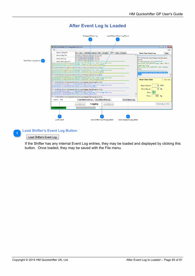
HM Quickshifter GP User's Guide
Copyright © 2014 HM Quickshifter UK, Ltd. After Event Log Is Loaded -- Page 65 of 81
After Event Log Is Loaded
Load Shifter's Event Log Button
If the Shifter has any internal Event Log entries, they may be loaded and displayed by clicking thisbutton. Once loaded, they may be saved with the File menu.
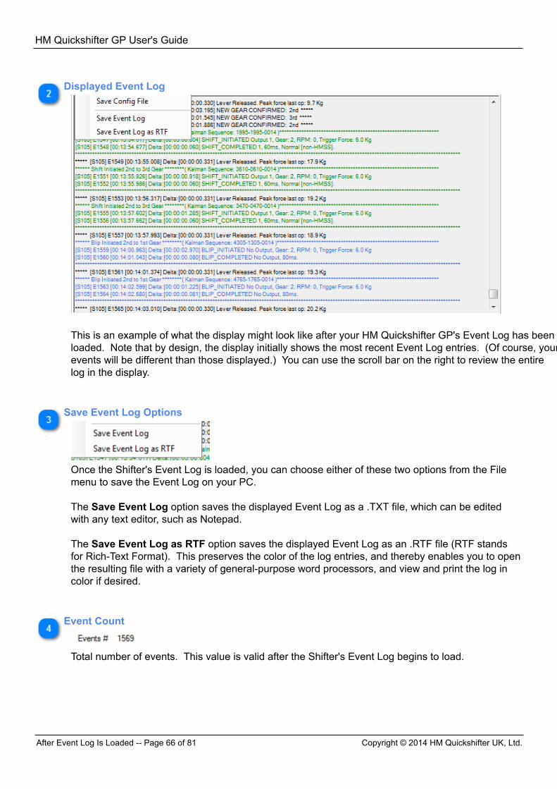
HM Quickshifter GP User's Guide
After Event Log Is Loaded -- Page 66 of 81 Copyright © 2014 HM Quickshifter UK, Ltd.
Displayed Event Log
This is an example of what the display might look like after your HM Quickshifter GP's Event Log has beenloaded. Note that by design, the display initially shows the most recent Event Log entries. (Of course, yourevents will be different than those displayed.) You can use the scroll bar on the right to review the entirelog in the display.
Save Event Log Options
Once the Shifter's Event Log is loaded, you can choose either of these two options from the Filemenu to save the Event Log on your PC. The Save Event Log option saves the displayed Event Log as a .TXT file, which can be editedwith any text editor, such as Notepad. The Save Event Log as RTF option saves the displayed Event Log as an .RTF file (RTF standsfor Rich-Text Format). This preserves the color of the log entries, and thereby enables you to openthe resulting file with a variety of general-purpose word processors, and view and print the log incolor if desired.
Event Count
Total number of events. This value is valid after the Shifter's Event Log begins to load.
HM Quickshifter GP User's Guide
Copyright © 2014 HM Quickshifter UK, Ltd. Stats Tab -- Page 67 of 81
Clear Shifter's Event Log Button
Click this button to erase the Event Log stored in the Shifter. CAUTION: Once the Shifter'sEvent Log is erased, it cannot be retrieved. Once this step is completed, the displayed log is alsocleared, and can no longer be saved to your PC.
Clear Displayed Log Button
Click this button to clear ONLY the displayed log data WITHOUT erasing the Shifter's Event Log. This leaves the Shifter's Event Log intact, enabling it to be retrieved at a later time. Once this stepis completed, the displayed log can no longer be saved to your PC.
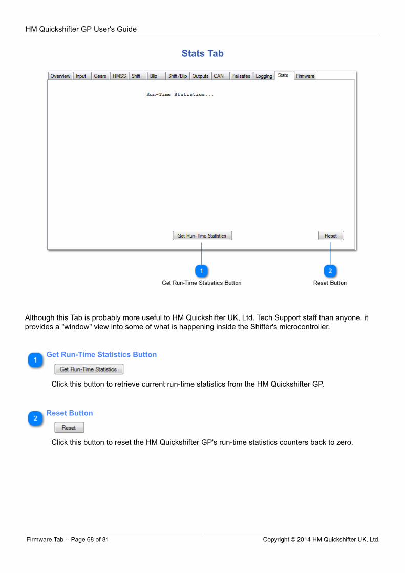
HM Quickshifter GP User's Guide
Firmware Tab -- Page 68 of 81 Copyright © 2014 HM Quickshifter UK, Ltd.
Stats Tab
Although this Tab is probably more useful to HM Quickshifter UK, Ltd. Tech Support staff than anyone, itprovides a "window" view into some of what is happening inside the Shifter's microcontroller.
Get Run-Time Statistics Button
Click this button to retrieve current run-time statistics from the HM Quickshifter GP.
Reset Button
Click this button to reset the HM Quickshifter GP's run-time statistics counters back to zero.
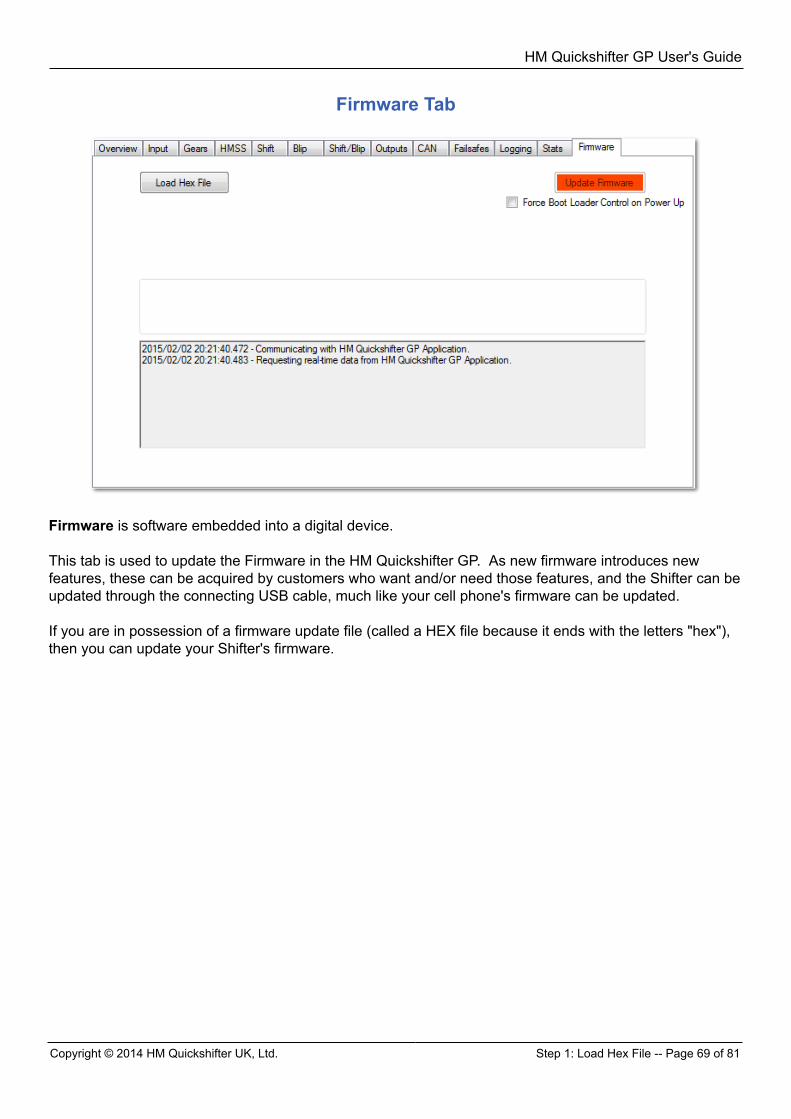
HM Quickshifter GP User's Guide
Copyright © 2014 HM Quickshifter UK, Ltd. Step 1: Load Hex File -- Page 69 of 81
Firmware Tab
Firmware is software embedded into a digital device. This tab is used to update the Firmware in the HM Quickshifter GP. As new firmware introduces newfeatures, these can be acquired by customers who want and/or need those features, and the Shifter can beupdated through the connecting USB cable, much like your cell phone's firmware can be updated. If you are in possession of a firmware update file (called a HEX file because it ends with the letters "hex"),then you can update your Shifter's firmware.
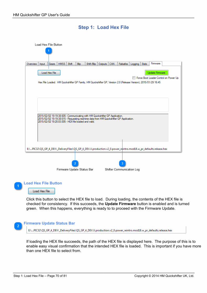
HM Quickshifter GP User's Guide
Step 1: Load Hex File -- Page 70 of 81 Copyright © 2014 HM Quickshifter UK, Ltd.
Step 1: Load Hex File
Load Hex File Button
Click this button to select the HEX file to load. During loading, the contents of the HEX file ischecked for consistency. If this succeeds, the Update Firmware button is enabled and is turnedgreen. When this happens, everything is ready to to proceed with the Firmware Update.
Firmware Update Status Bar
If loading the HEX file succeeds, the path of the HEX file is displayed here. The purpose of this is toenable easy visual confirmation that the intended HEX file is loaded. This is important if you have morethan one HEX file to select from.
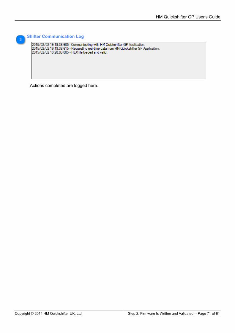
HM Quickshifter GP User's Guide
Copyright © 2014 HM Quickshifter UK, Ltd. Step 2: Firmware Is Written and Validated -- Page 71 of 81
Shifter Communication Log
Actions completed are logged here.
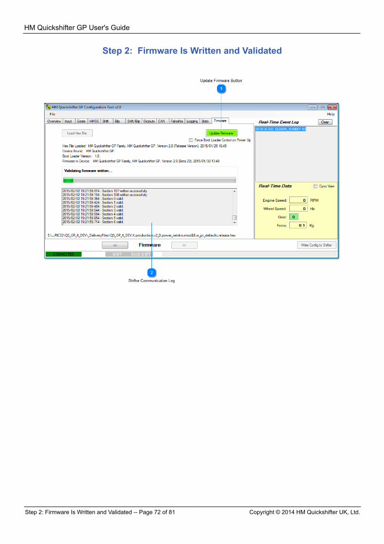
HM Quickshifter GP User's Guide
Step 2: Firmware Is Written and Validated -- Page 72 of 81 Copyright © 2014 HM Quickshifter UK, Ltd.
Step 2: Firmware Is Written and Validated
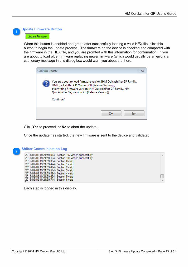
HM Quickshifter GP User's Guide
Copyright © 2014 HM Quickshifter UK, Ltd. Step 3: Firmware Update Completed -- Page 73 of 81
Update Firmware Button
When this button is enabled and green after successfully loading a valid HEX file, click thisbutton to begin the update process. The firmware on the device is checked and compared withthe firmware in the HEX file, and you are promted with this information for confirmation. If youare about to load older firmware replacing newer firmware (which would usually be an error), acautionary message in this dialog box would warn you about that here.
Click Yes to proceed, or No to abort the update. Once the update has started, the new firmware is sent to the device and validated.
Shifter Communication Log
Each step is logged in this display.
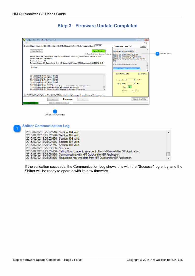
HM Quickshifter GP User's Guide
Step 3: Firmware Update Completed -- Page 74 of 81 Copyright © 2014 HM Quickshifter UK, Ltd.
Step 3: Firmware Update Completed
Shifter Communication Log
If the validation succeeds, the Communication Log shows this with the "Success" log entry, and theShifter will be ready to operate with its new firmware.
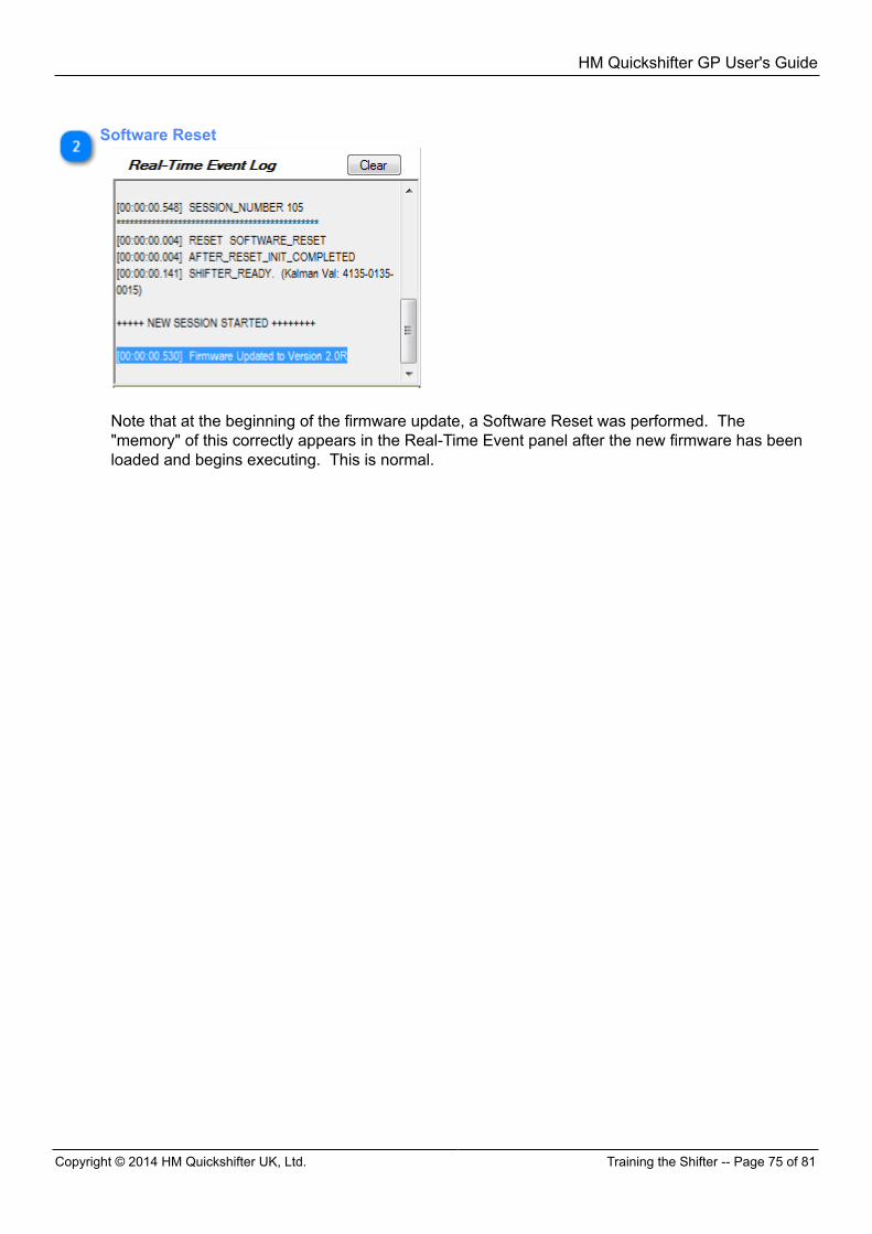
HM Quickshifter GP User's Guide
Copyright © 2014 HM Quickshifter UK, Ltd. Training the Shifter -- Page 75 of 81
Software Reset
Note that at the beginning of the firmware update, a Software Reset was performed. The"memory" of this correctly appears in the Real-Time Event panel after the new firmware has beenloaded and begins executing. This is normal.
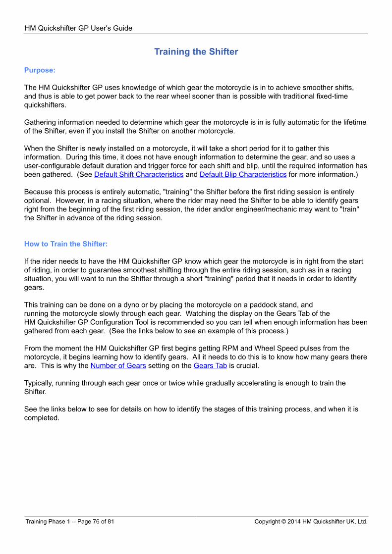
HM Quickshifter GP User's Guide
Training Phase 1 -- Page 76 of 81 Copyright © 2014 HM Quickshifter UK, Ltd.
Training the Shifter Purpose: The HM Quickshifter GP uses knowledge of which gear the motorcycle is in to achieve smoother shifts,and thus is able to get power back to the rear wheel sooner than is possible with traditional fixed-timequickshifters. Gathering information needed to determine which gear the motorcycle is in is fully automatic for the lifetimeof the Shifter, even if you install the Shifter on another motorcycle. When the Shifter is newly installed on a motorcycle, it will take a short period for it to gather thisinformation. During this time, it does not have enough information to determine the gear, and so uses auser-configurable default duration and trigger force for each shift and blip, until the required information hasbeen gathered. (See Default Shift Characteristics and Default Blip Characteristics for more information.) Because this process is entirely automatic, "training" the Shifter before the first riding session is entirelyoptional. However, in a racing situation, where the rider may need the Shifter to be able to identify gearsright from the beginning of the first riding session, the rider and/or engineer/mechanic may want to "train"the Shifter in advance of the riding session. How to Train the Shifter: If the rider needs to have the HM Quickshifter GP know which gear the motorcycle is in right from the startof riding, in order to guarantee smoothest shifting through the entire riding session, such as in a racingsituation, you will want to run the Shifter through a short "training" period that it needs in order to identifygears. This training can be done on a dyno or by placing the motorcycle on a paddock stand, andrunning the motorcycle slowly through each gear. Watching the display on the Gears Tab of theHM Quickshifter GP Configuration Tool is recommended so you can tell when enough information has beengathered from each gear. (See the links below to see an example of this process.) From the moment the HM Quickshifter GP first begins getting RPM and Wheel Speed pulses from themotorcycle, it begins learning how to identify gears. All it needs to do this is to know how many gears thereare. This is why the Number of Gears setting on the Gears Tab is crucial. Typically, running through each gear once or twice while gradually accelerating is enough to train theShifter. See the links below to see for details on how to identify the stages of this training process, and when it iscompleted.
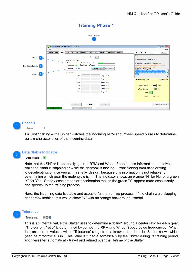
HM Quickshifter GP User's Guide
Copyright © 2014 HM Quickshifter UK, Ltd. Training Phase 1 -- Page 77 of 81
Training Phase 1
Phase 1
1 = Just Starting -- the Shifter watches the incoming RPM and Wheel Speed pulses to determinecertain characteristics of the incoming data.
Data Stable Indicator
Note that the Shifter intentionally ignores RPM and Wheel-Speed pulse information it receiveswhile the chain is slapping or while the gearbox is lashing -- transitioning from acceleratingto decelerating, or vice versa. This is by design, because this information is not reliable fordetermining which gear the motorcycle is in. The indicator shows an orange "N" for No, or a green"Y" for Yes. Steady acceleration or deceleration makes the green "Y" appear more consistently,and speeds up the training process. Here, the incoming data is stable and useable for the training process. If the chain were slappingor gearbox lashing, this would show "N" with an orange background instead.
Tolerance
This is an internal value the Shifter uses to determine a "band" around a center ratio for each gear. The current "ratio" is determined by comparing RPM and Wheel Speed pulse frequencies. Whenthe current ratio value is within "Tolerance" range from a known ratio, then the Shifter knows whichgear the motorcycle is in. This value is tuned automatically by the Shifter during its training period,and thereafter automatically tuned and refined over the lifetime of the Shifter.

HM Quickshifter GP User's Guide
Training Phase 2 -- Page 78 of 81 Copyright © 2014 HM Quickshifter UK, Ltd.
Phase 1 Progress
These two progress bars show progress through the training steps.
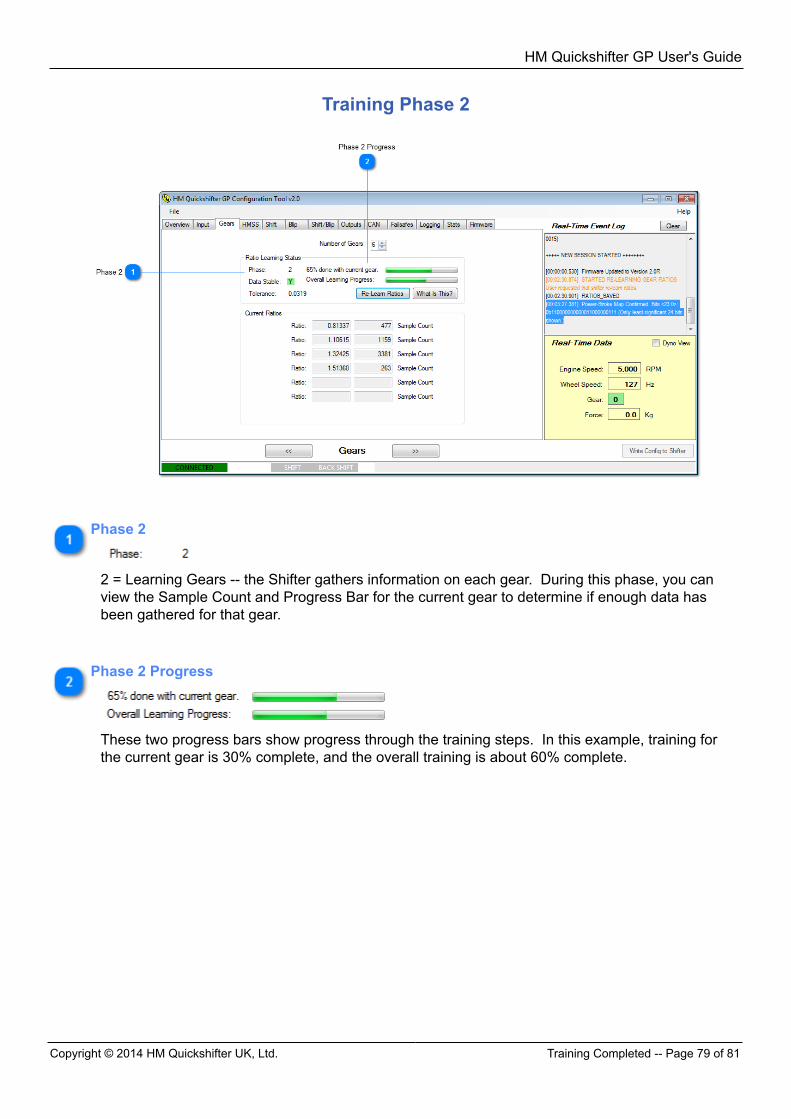
HM Quickshifter GP User's Guide
Copyright © 2014 HM Quickshifter UK, Ltd. Training Completed -- Page 79 of 81
Training Phase 2
Phase 2
2 = Learning Gears -- the Shifter gathers information on each gear. During this phase, you canview the Sample Count and Progress Bar for the current gear to determine if enough data hasbeen gathered for that gear.
Phase 2 Progress
These two progress bars show progress through the training steps. In this example, training forthe current gear is 30% complete, and the overall training is about 60% complete.
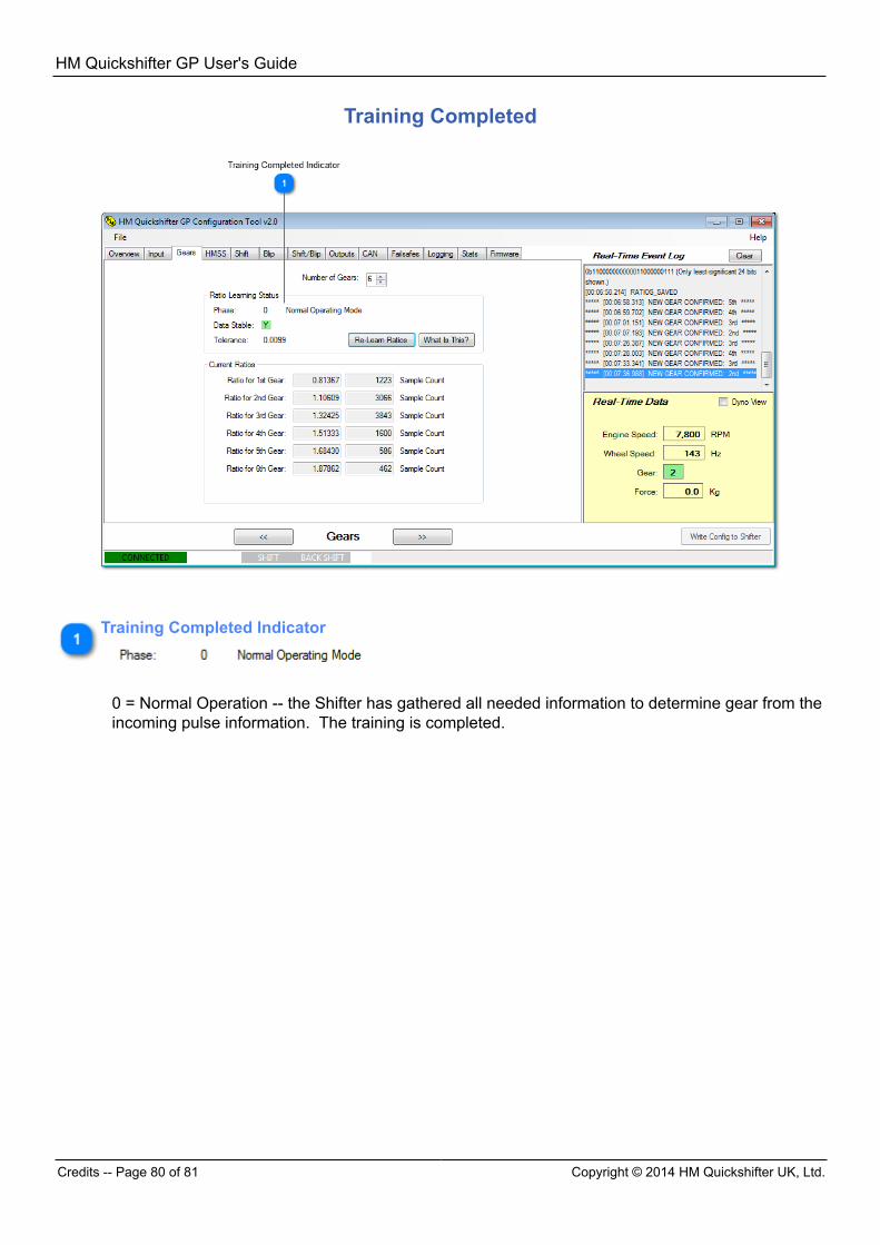
HM Quickshifter GP User's Guide
Credits -- Page 80 of 81 Copyright © 2014 HM Quickshifter UK, Ltd.
Training Completed
Training Completed Indicator
0 = Normal Operation -- the Shifter has gathered all needed information to determine gear from theincoming pulse information. The training is completed.
HM Quickshifter GP User's Guide
Copyright © 2014 HM Quickshifter UK, Ltd. Credits -- Page 81 of 81
Credits "HM Quickshifter GP", "HM Quickshifter GP Configuration Tool", "HM Seamless-Shift (HMSS) Technology",the "Oval HM Quickshifter Logo" and the "HM Quickshifter Logo" are trademarks owned byHM Quickshifter UK, Ltd. and are used with its permission. "Windows", "Windows 7", "Windows 8", and "Notepad" are trademarks owned by Microsoft.