Embed Size (px)
Citation preview
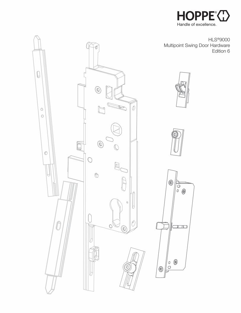
HLS®9000Multipoint Swing Door Hardware
Edition 6
2 Call 1-888-485-4885 www.us.hoppe.com
● Multiple locking points for improved weather sealing
● All stainless steel construction for superior corrosion resistance
● Proven reliability in coastal environments
● Low maintenance
● Robust stainless steel latch and dead bolt
● Mishandling device prevents accidental use
● Made in the United States
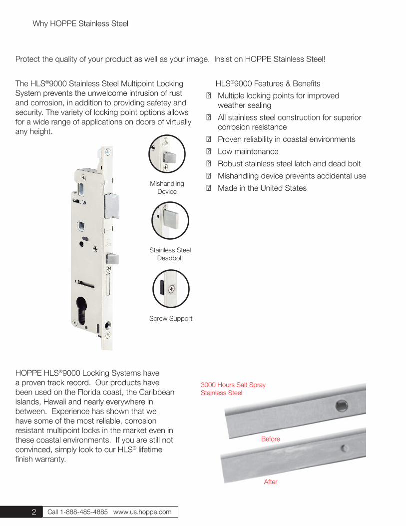
The HLS®9000 Stainless Steel Multipoint Locking System prevents the unwelcome intrusion of rust and corrosion, in addition to providing safetey and security. The variety of locking point options allows for a wide range of applications on doors of virtually any height.
HOPPE HLS®9000 Locking Systems have a proven track record. Our products have been used on the Florida coast, the Caribbean islands, Hawaii and nearly everywhere in between. Experience has shown that we have some of the most reliable, corrosion resistant multipoint locks in the market even in these coastal environments. If you are still not convinced, simply look to our HLS® lifetime finish warranty.
Why HOPPE Stainless Steel
HLS®9000 Features & Benefits
Screw Support
MishandlingDevice
Stainless SteelDeadbolt
Protect the quality of your product as well as your image. Insist on HOPPE Stainless Steel!
3000 Hours Salt Spray Stainless Steel
Before
After
3
16mm Faceplate
Swing Hook Page 4
Swing Hook + Shootbolt Page 6
Tongue Page 8
Tongue + Shootbolt Page 10
Shootbolt Page 12
Roundbolt Page 14
Roundbolt + Shootbolt Page 15
Two Roller Page 16
Roller + Shootbolt Page 17
Four Roller Page 18
Automatic Tongue Page 19
Automatic Two Roller Page 20
Automatic Four Roller Page 21
20mm Faceplate
Tongue Page 22
Tongue + Shootbolt Page 24
Shootbolt Page 26
16mm Faceplate Inactive
Inactive Page 28
20mm Faceplate Inactive
Inactive Page 34
Additional Hardware
Inactive Flushbolt Page 38
Single Point Page 39
Strikes Page 40
Accessories Page 45
Optional Items Page 46
Eurogrooves Page 47
How to Order & Door Handing Page 48
Terminology Page 49
Installation & Adjustments Page 50
Sales Tools Page 53
Glossary Page 54
4 Call 1-888-485-4885 www.us.hoppe.com
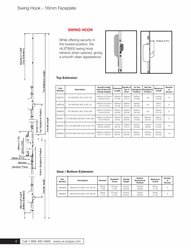
19.5mm (0.77) While offering security in the locked position, the HLS®9000 swing hook retracts when opened, giving a smooth clean appearance.
SWING HOOK
Part Number Description Backset Deadbolt
ThrowHandle Height
Bottom Swing Hook
Position
Maximum Cutoff
Number of
Screws
3868868 M/35/25 914 SW1 753 16S 30 35mm(1.38)
25.4mm(1.00)
914mm(36.00)
753mm(29.65)
30mm(1.18) 5
3868876 M/45/25 914 SW1 753 16S 30 45mm(1.77)
25.4mm(1.00)
914mm(36.00)
753mm(29.65)
30mm(1.18) 5
Gear / Bottom Extension
Top Extension
Swing Hook - 16mm Faceplate
PartNumber Description
Overall Length(with 914mm 36"Handle Height)
ExtensionLength
Handle toTop of Door
1st TopSwinghook
Position
2nd TopSwinghook
Position
MaximumCutoff
Numberof
Screws
3868770 M 1058 SW1 500 16-SC 418 1595mm-2013mm(62.80-79.25)
1058mm(41.65)
1099mm(43.27)
500mm(19.69) n/a 418mm
(16.46) 6
3868796 M 1058 SW1 900 16-SC 18 1995mm-2013mm(78.54-79.25)
1058mm(41.65)
1099mm(43.27)
900mm(35.43) n/a 18mm
(0.71) 6
3868809 M 1388 SW1 900 16-SC 348 1995mm-2343mm(78.54-92.24)
1388mm(54.65)
1429mm(56.26)
900mm(35.43) n/a 348mm
(13.70) 8
3868817 M 1388 SW2 500/900 16-SC 348 1995mm-2343mm(78.54-92.24)
1388mm(54.65)
1429mm(56.26)
500mm(19.69)
900mm(35.43)
348mm(13.70) 8
3868825 M 1745 SW2 600/1193 16-SC 412 2288mm-2700mm(90.08-106.30)
1745mm(68.70)
1786mm(70.31)
600mm(23.62)
1193mm(46.97)
412mm(16.22) 10
3868833 M 2270 SW2 600/1500 16-SC 630 2595mm-3225mm(102.17-126.97)
2270mm(89.37)
2311mm(90.98)
600mm(23.62)
1500mm(59.05)
630mm(24.80) 12
5
Part Number Description Backset Deadbolt
ThrowHandle Height
Bottom Swing Hook
Position
Maximum Cutoff
Number of
Screws
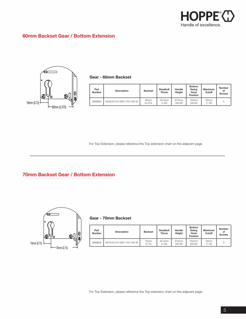
3868884 M/60/25 914 SW1 753 16S 30 60mm(2.375)
25.4mm(1.00)
914mm(36.00)
753mm(29.65)
30mm(1.18) 5
Part Number Description Backset Deadbolt
ThrowHandle Height
Bottom Swing Hook
Position
Maximum Cutoff
Number of
Screws
3868892 M/70/25 914 SW1 753 16S 30 70mm(2.75)
25.4mm(1.00)
914mm(36.00)
753mm(29.65)
30mm(1.18) 5
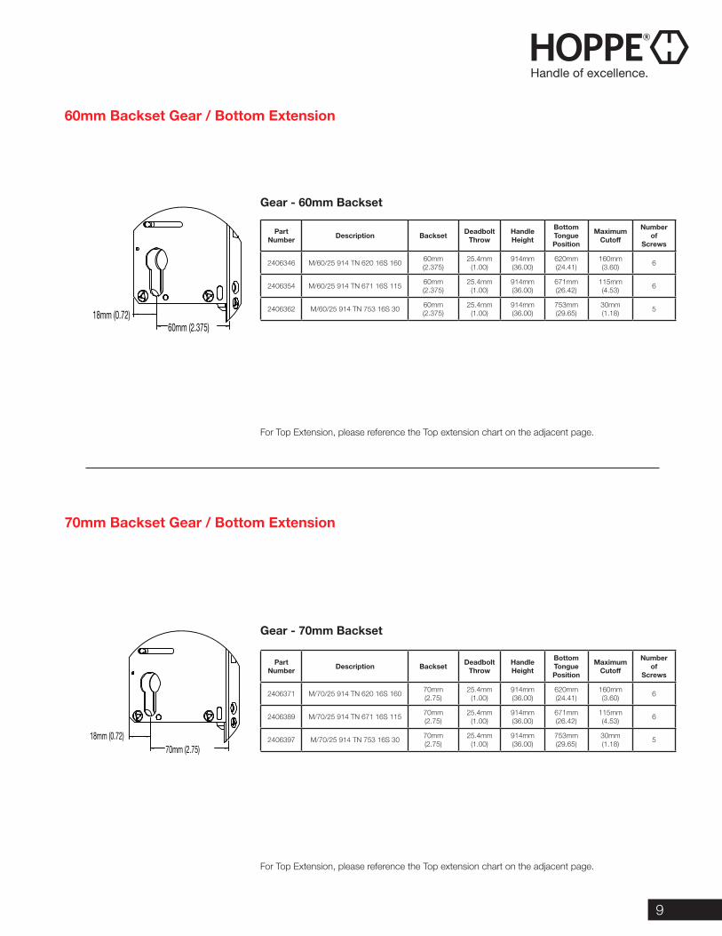
For Top Extension, please reference the Top extension chart on the adjacent page.
For Top Extension, please reference the Top extension chart on the adjacent page.
Gear - 60mm Backset
Gear - 70mm Backset
60mm Backset Gear / Bottom Extension
70mm Backset Gear / Bottom Extension
70mm (2.75)18mm (0.72)
60mm (2.375)18mm (0.72)
6 Call 1-888-485-4885 www.us.hoppe.com
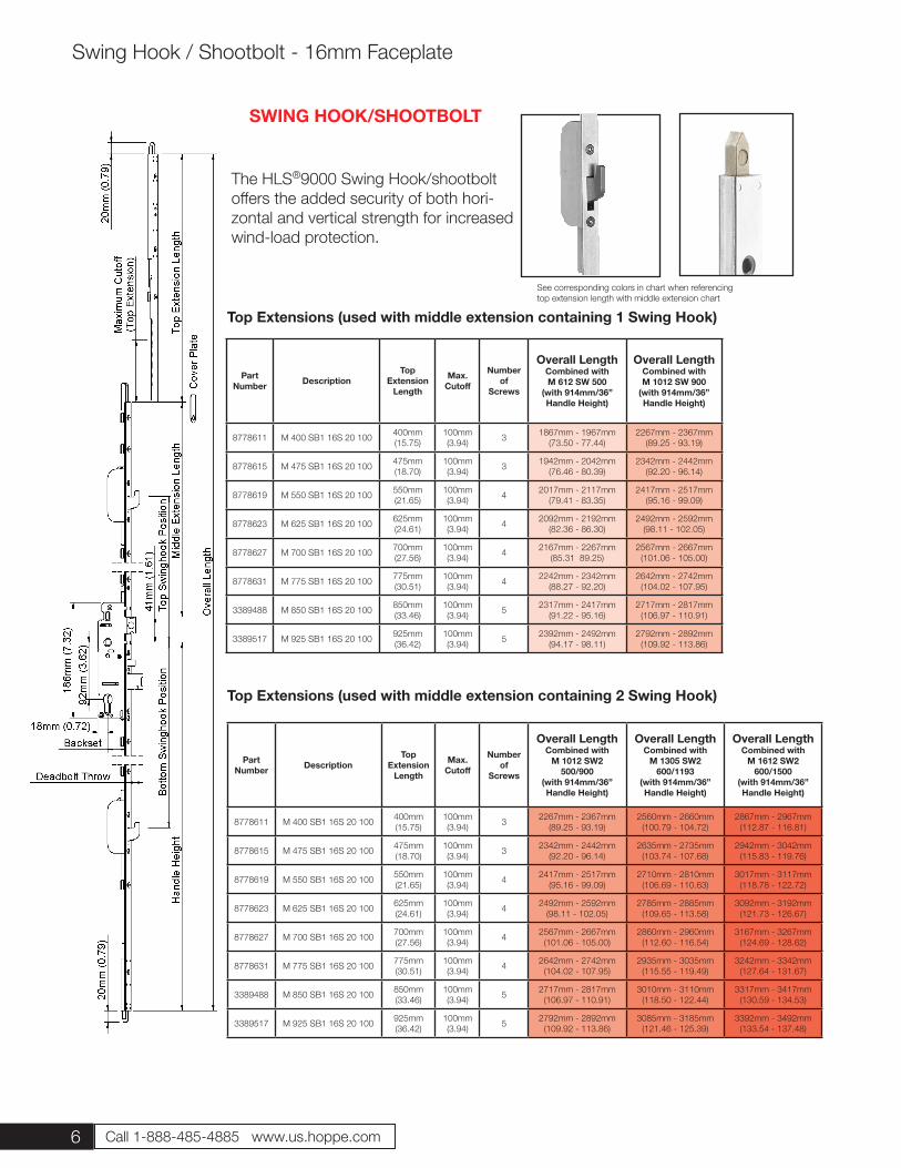
The HLS®9000 Swing Hook/shootbolt offers the added security of both hori-zontal and vertical strength for increased wind-load protection.
SWING HOOK/SHOOTBOLT
Top Extensions (used with middle extension containing 1 Swing Hook)
Top Extensions (used with middle extension containing 2 Swing Hook)
Part Number Description
TopExtension
Length
Max. Cutoff
Number of
Screws
Overall Length Combined with M 612 SW 500
(with 914mm/36” Handle Height)
Overall Length Combined with M 1012 SW 900
(with 914mm/36” Handle Height)
8778611 M 400 SB1 16S 20 100 400mm(15.75)
100mm(3.94) 3 1867mm - 1967mm
(73.50 - 77.44)2267mm - 2367mm
(89.25 - 93.19)
8778615 M 475 SB1 16S 20 100 475mm(18.70)
100mm(3.94) 3 1942mm - 2042mm
(76.46 - 80.39)2342mm - 2442mm
(92.20 - 96.14)
8778619 M 550 SB1 16S 20 100 550mm(21.65)
100mm(3.94) 4 2017mm - 2117mm
(79.41 - 83.35)2417mm - 2517mm
(95.16 - 99.09)
8778623 M 625 SB1 16S 20 100 625mm(24.61)
100mm(3.94) 4 2092mm - 2192mm
(82.36 - 86.30)2492mm - 2592mm
(98.11 - 102.05)
8778627 M 700 SB1 16S 20 100 700mm(27.56)
100mm(3.94) 4 2167mm - 2267mm
(85.31 89.25)2567mm - 2667mm
(101.06 - 105.00)
8778631 M 775 SB1 16S 20 100 775mm(30.51)
100mm(3.94) 4 2242mm - 2342mm
(88.27 - 92.20)2642mm - 2742mm
(104.02 - 107.95)
3389488 M 850 SB1 16S 20 100 850mm(33.46)
100mm(3.94) 5 2317mm - 2417mm
(91.22 - 95.16)2717mm - 2817mm
(106.97 - 110.91)
3389517 M 925 SB1 16S 20 100 925mm(36.42)
100mm(3.94) 5 2392mm - 2492mm
(94.17 - 98.11)2792mm - 2892mm
(109.92 - 113.86)
Part Number Description
TopExtension
Length
Max. Cutoff
Number of
Screws
Overall Length Combined with
M 1012 SW2 500/900
(with 914mm/36” Handle Height)
Overall Length Combined with
M 1305 SW2 600/1193
(with 914mm/36” Handle Height)
Overall LengthCombined with
M 1612 SW2 600/1500
(with 914mm/36” Handle Height)
8778611 M 400 SB1 16S 20 100 400mm(15.75)
100mm(3.94) 3 2267mm - 2367mm
(89.25 - 93.19)2560mm - 2660mm
(100.79 - 104.72)2867mm - 2967mm
(112.87 - 116.81)
8778615 M 475 SB1 16S 20 100 475mm(18.70)
100mm(3.94) 3 2342mm - 2442mm
(92.20 - 96.14)2635mm - 2735mm
(103.74 - 107.68)2942mm - 3042mm
(115.83 - 119.76)
8778619 M 550 SB1 16S 20 100 550mm(21.65)
100mm(3.94) 4 2417mm - 2517mm
(95.16 - 99.09)2710mm - 2810mm
(106.69 - 110.63)3017mm - 3117mm
(118.78 - 122.72)
8778623 M 625 SB1 16S 20 100 625mm(24.61)
100mm(3.94) 4 2492mm - 2592mm
(98.11 - 102.05)2785mm - 2885mm
(109.65 - 113.58)3092mm - 3192mm
(121.73 - 126.67)
8778627 M 700 SB1 16S 20 100 700mm(27.56)
100mm(3.94) 4 2567mm - 2667mm
(101.06 - 105.00)2860mm - 2960mm
(112.60 - 116.54)3167mm - 3267mm
(124.69 - 128.62)
8778631 M 775 SB1 16S 20 100 775mm(30.51)
100mm(3.94) 4 2642mm - 2742mm
(104.02 - 107.95)2935mm - 3035mm
(115.55 - 119.49)3242mm - 3342mm
(127.64 - 131.67)
3389488 M 850 SB1 16S 20 100 850mm(33.46)
100mm(3.94) 5 2717mm - 2817mm
(106.97 - 110.91)3010mm - 3110mm
(118.50 - 122.44)3317mm - 3417mm
(130.59 - 134.53)
3389517 M 925 SB1 16S 20 100 925mm(36.42)
100mm(3.94) 5 2792mm - 2892mm
(109.92 - 113.86)3085mm - 3185mm
(121.46 - 125.39)3392mm - 3492mm
(133.54 - 137.48)
Swing Hook / Shootbolt - 16mm Faceplate
See corresponding colors in chart when referencingtop extension length with middle extension chart
7
2875118 Cover Plate
Swing Hook / Shootbolt - 16mm Faceplate
Part Number Description Middle
ExtensionTop Swing
Hook Position
Second Swing Hook
Position
Maximum Cutoff
Number of Screws
3622868 M 612 SW1 500 16S 612mm(24.09)
500mm(19.69) N/A N/A 4
3644160 M 1012 SW1 900 16S 1012mm(39.84)
900mm(35.43) N/A N/A 6
Part Number Description Backset Deadbolt
ThrowHandle Height
Bottom Swing Hook
Position
Max. Cutoff
Number of
Screws
3814747 M/35/25 914 SW1SB1 620 16S 20 35mm(1.38)
25mm(1.00)
914mm(36.00)
620mm(24.41) N/A 4
3622876 M/45/25 914 SW1SB1 620 16S 20 45mm(1.77)
25mm(1.00)
914mm(36.00)
620mm(24.41) N/A 4
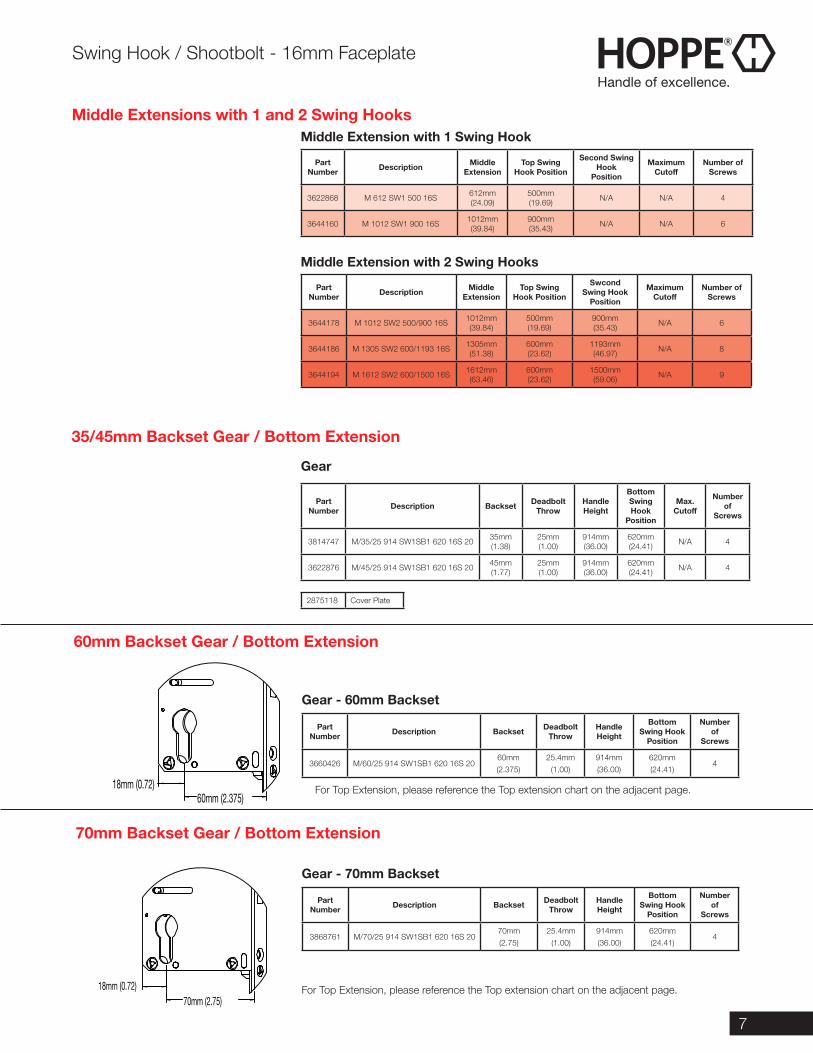
Middle Extension with 1 Swing Hook
Middle Extension with 2 Swing Hooks
Gear
Part Number Description Backset Deadbolt
ThrowHandle Height
Bottom Swing Hook
Position
Number of
Screws
3660426 M/60/25 914 SW1SB1 620 16S 2060mm(2.375)
25.4mm(1.00)
914mm(36.00)
620mm(24.41)
4
Part Number Description Backset Deadbolt
ThrowHandle Height
Bottom Swing Hook
Position
Number of
Screws
3868761 M/70/25 914 SW1SB1 620 16S 2070mm(2.75)
25.4mm(1.00)
914mm(36.00)
620mm(24.41)
4
For Top Extension, please reference the Top extension chart on the adjacent page.
For Top Extension, please reference the Top extension chart on the adjacent page.
Gear - 60mm Backset
Gear - 70mm Backset
70mm Backset Gear / Bottom Extension
60mm Backset Gear / Bottom Extension
35/45mm Backset Gear / Bottom Extension
Middle Extensions with 1 and 2 Swing Hooks
Part Number Description Middle
ExtensionTop Swing
Hook Position
Swcond Swing Hook
Position
Maximum Cutoff
Number of Screws
3644178 M 1012 SW2 500/900 16S 1012mm(39.84)
500mm(19.69)
900mm(35.43) N/A 6
3644186 M 1305 SW2 600/1193 16S 1305mm(51.38)
600mm(23.62)
1193mm(46.97) N/A 8
3644194 M 1612 SW2 600/1500 16S 1612mm(63.46)
600mm(23.62)
1500mm(59.06) N/A 9
70mm (2.75)18mm (0.72)
60mm (2.375)18mm (0.72)
8 Call 1-888-485-4885 www.us.hoppe.com
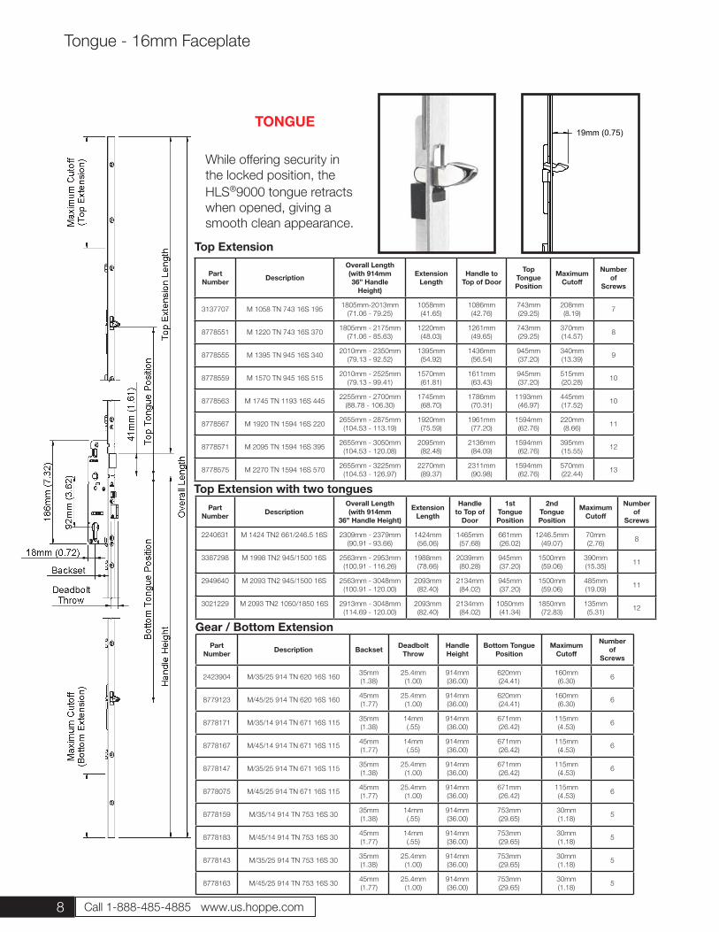
19mm (0.75)
While offering security in the locked position, the HLS®9000 tongue retracts when opened, giving a smooth clean appearance.
TONGUE
Part Number Description
Overall Length(with 914mm36” Handle
Height)
Extension Length
Handle to Top of Door
Top Tongue Position
Maximum Cutoff
Numberof
Screws
3137707 M 1058 TN 743 16S 195 1805mm-2013mm(71.06 - 79.25)
1058mm(41.65)
1086mm(42.76)
743mm(29.25)
208mm(8.19) 7
8778551 M 1220 TN 743 16S 370 1805mm - 2175mm(71.06 - 85.63)
1220mm(48.03)
1261mm(49.65)
743mm(29.25)
370mm(14.57) 8
8778555 M 1395 TN 945 16S 340 2010mm - 2350mm(79.13 - 92.52)
1395mm(54.92)
1436mm(56.54)
945mm(37.20)
340mm(13.39) 9
8778559 M 1570 TN 945 16S 515 2010mm - 2525mm(79.13 - 99.41)
1570mm(61.81)
1611mm(63.43)
945mm(37.20)
515mm(20.28) 10
8778563 M 1745 TN 1193 16S 445 2255mm - 2700mm(88.78 - 106.30)
1745mm(68.70)
1786mm(70.31)
1193mm(46.97)
445mm(17.52) 10
8778567 M 1920 TN 1594 16S 220 2655mm - 2875mm(104.53 - 113.19)
1920mm(75.59)
1961mm(77.20)
1594mm(62.76)
220mm(8.66) 11
8778571 M 2095 TN 1594 16S 395 2655mm - 3050mm(104.53 - 120.08)
2095mm(82.48)
2136mm(84.09)
1594mm(62.76)
395mm(15.55) 12
8778575 M 2270 TN 1594 16S 570 2655mm - 3225mm(104.53 - 126.97)
2270mm(89.37)
2311mm(90.98)
1594mm(62.76)
570mm(22.44) 13
Part Number Description Backset Deadbolt
ThrowHandle Height
Bottom Tongue Position
Maximum Cutoff
Number of
Screws
2423904 M/35/25 914 TN 620 16S 160 35mm(1.38)
25.4mm(1.00)
914mm(36.00)
620mm(24.41)
160mm(6.30) 6
8779123 M/45/25 914 TN 620 16S 160 45mm(1.77)
25.4mm(1.00)
914mm(36.00)
620mm(24.41)
160mm(6.30) 6
8778171 M/35/14 914 TN 671 16S 115 35mm(1.38)
14mm(.55)
914mm(36.00)
671mm(26.42)
115mm(4.53) 6
8778167 M/45/14 914 TN 671 16S 115 45mm(1.77)
14mm(.55)
914mm(36.00)
671mm(26.42)
115mm(4.53) 6
8778147 M/35/25 914 TN 671 16S 115 35mm(1.38)
25.4mm(1.00)
914mm(36.00)
671mm(26.42)
115mm(4.53) 6
8778075 M/45/25 914 TN 671 16S 115 45mm(1.77)
25.4mm(1.00)
914mm(36.00)
671mm(26.42)
115mm(4.53) 6
8778159 M/35/14 914 TN 753 16S 30 35mm(1.38)
14mm(.55)
914mm(36.00)
753mm(29.65)
30mm(1.18) 5
8778183 M/45/14 914 TN 753 16S 30 45mm(1.77)
14mm(.55)
914mm(36.00)
753mm(29.65)
30mm(1.18) 5
8778143 M/35/25 914 TN 753 16S 30 35mm(1.38)
25.4mm(1.00)
914mm(36.00)
753mm(29.65)
30mm(1.18) 5
8778163 M/45/25 914 TN 753 16S 30 45mm(1.77)
25.4mm(1.00)
914mm(36.00)
753mm(29.65)
30mm(1.18) 5
Gear / Bottom Extension
Top Extension
Tongue - 16mm Faceplate
Top Extension with two tonguesPart
Number DescriptionOverall Length(with 914mm
36” Handle Height)
Extension Length
Handle to Top of
Door
1st Tongue Position
2nd Tongue Position
Maximum Cutoff
Numberof
Screws
2240631 M 1424 TN2 661/246.5 16S 2309mm - 2379mm(90.91 - 93.66)
1424mm (56.06)
1465mm (57.68)
661mm (26.02)
1246.5mm (49.07)
70mm(2.76) 8
3387298 M 1998 TN2 945/1500 16S 2563mm - 2953mm(100.91 - 116.26)
1988mm (78.66)
2039mm (80.28)
945mm (37.20)
1500mm (59.06)
390mm(15.35) 11
2949640 M 2093 TN2 945/1500 16S 2563mm - 3048mm(100.91 - 120.00)
2093mm (82.40)
2134mm (84.02)
945mm (37.20)
1500mm (59.06)
485mm(19.09) 11
3021229 M 2093 TN2 1050/1850 16S 2913mm - 3048mm (114.69 - 120.00)
2093mm (82.40)
2134mm (84.02)
1050mm (41.34)
1850mm (72.83)
135mm(5.31) 12
9
Part Number Description Backset Deadbolt
ThrowHandle Height
Bottom Tongue Position
Maximum Cutoff
Number of
Screws
2406346 M/60/25 914 TN 620 16S 160 60mm(2.375)
25.4mm(1.00)
914mm(36.00)
620mm(24.41)
160mm(3.60) 6
2406354 M/60/25 914 TN 671 16S 115 60mm(2.375)
25.4mm(1.00)
914mm(36.00)
671mm(26.42)
115mm(4.53) 6
2406362 M/60/25 914 TN 753 16S 30 60mm(2.375)
25.4mm(1.00)
914mm(36.00)
753mm(29.65)
30mm(1.18) 5
Part Number Description Backset Deadbolt
ThrowHandle Height
Bottom Tongue Position
Maximum Cutoff
Number of
Screws
2406371 M/70/25 914 TN 620 16S 160 70mm(2.75)
25.4mm(1.00)
914mm(36.00)
620mm(24.41)
160mm(3.60) 6
2406389 M/70/25 914 TN 671 16S 115 70mm(2.75)
25.4mm(1.00)
914mm(36.00)
671mm(26.42)
115mm(4.53) 6
2406397 M/70/25 914 TN 753 16S 30 70mm(2.75)
25.4mm(1.00)
914mm(36.00)
753mm(29.65)
30mm(1.18) 5
For Top Extension, please reference the Top extension chart on the adjacent page.
For Top Extension, please reference the Top extension chart on the adjacent page.
Gear - 60mm Backset
Gear - 70mm Backset
60mm Backset Gear / Bottom Extension
70mm Backset Gear / Bottom Extension
70mm (2.75)18mm (0.72)
60mm (2.375)18mm (0.72)
10 Call 1-888-485-4885 www.us.hoppe.com
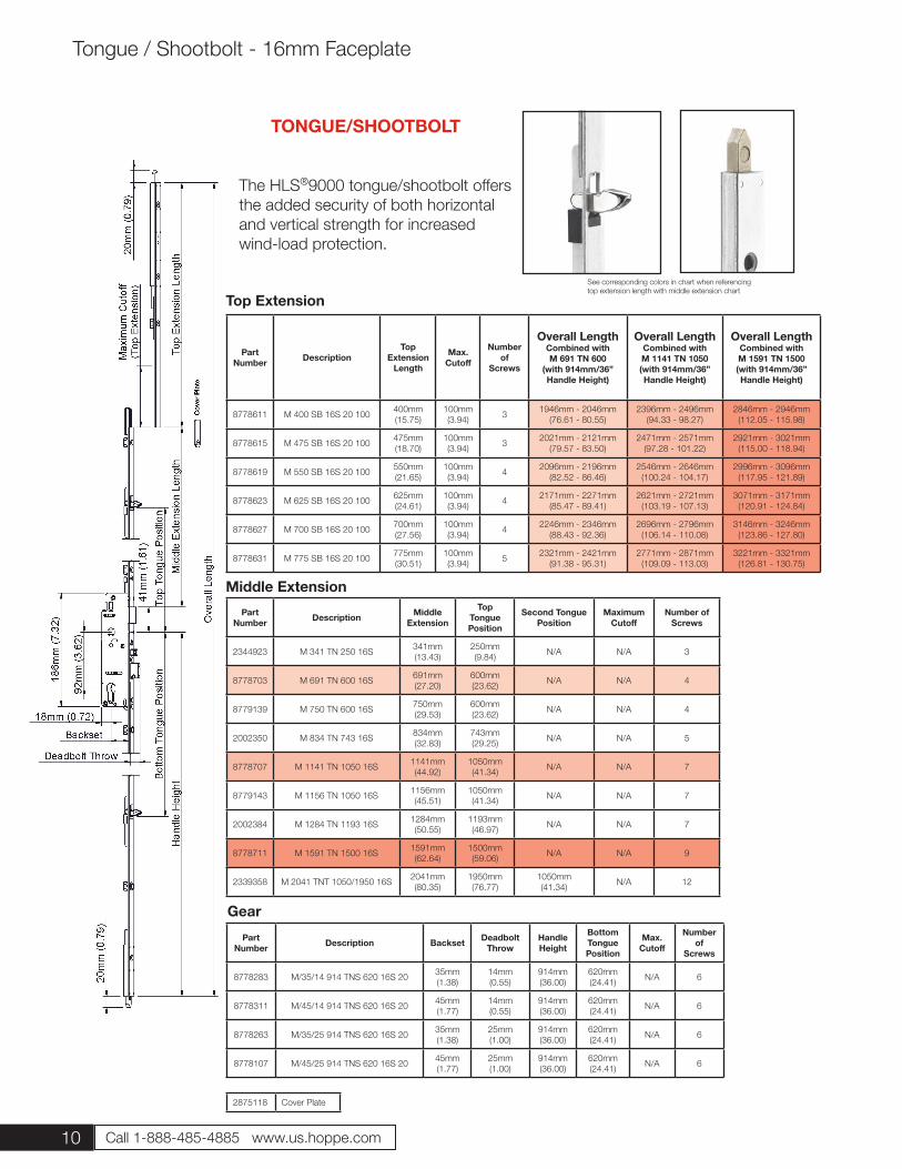
The HLS®9000 tongue/shootbolt offers the added security of both horizontal and vertical strength for increased wind-load protection.
TONGUE/SHOOTBOLT
Top Extension
Part Number Description
TopExtension
Length
Max. Cutoff
Number of
Screws
Overall Length Combined with M 691 TN 600
(with 914mm/36” Handle Height)
Overall Length Combined with M 1141 TN 1050(with 914mm/36” Handle Height)
Overall Length Combined with M 1591 TN 1500(with 914mm/36” Handle Height)
8778611 M 400 SB 16S 20 100 400mm(15.75)
100mm(3.94) 3 1946mm - 2046mm
(76.61 - 80.55)2396mm - 2496mm
(94.33 - 98.27)2846mm - 2946mm
(112.05 - 115.98)
8778615 M 475 SB 16S 20 100 475mm(18.70)
100mm(3.94) 3 2021mm - 2121mm
(79.57 - 83.50)2471mm - 2571mm
(97.28 - 101.22)2921mm - 3021mm
(115.00 - 118.94)
8778619 M 550 SB 16S 20 100 550mm(21.65)
100mm(3.94) 4 2096mm - 2196mm
(82.52 - 86.46)2546mm - 2646mm
(100.24 - 104.17)2996mm - 3096mm
(117.95 - 121.89)
8778623 M 625 SB 16S 20 100 625mm(24.61)
100mm(3.94) 4 2171mm - 2271mm
(85.47 - 89.41)2621mm - 2721mm
(103.19 - 107.13)3071mm - 3171mm
(120.91 - 124.84)
8778627 M 700 SB 16S 20 100 700mm(27.56)
100mm(3.94) 4 2246mm - 2346mm
(88.43 - 92.36)2696mm - 2796mm
(106.14 - 110.08)3146mm - 3246mm
(123.86 - 127.80)
8778631 M 775 SB 16S 20 100 775mm(30.51)
100mm(3.94) 5 2321mm - 2421mm
(91.38 - 95.31)2771mm - 2871mm
(109.09 - 113.03)3221mm - 3321mm
(126.81 - 130.75)
Part Number Description Middle
Extension
Top Tongue Position
Second TonguePosition
Maximum Cutoff
Number of Screws
2344923 M 341 TN 250 16S 341mm(13.43)
250mm(9.84) N/A N/A 3
8778703 M 691 TN 600 16S 691mm(27.20)
600mm(23.62) N/A N/A 4
8779139 M 750 TN 600 16S 750mm(29.53)
600mm(23.62) N/A N/A 4
2002350 M 834 TN 743 16S 834mm(32.83)
743mm(29.25) N/A N/A 5
8778707 M 1141 TN 1050 16S 1141mm(44.92)
1050mm(41.34) N/A N/A 7
8779143 M 1156 TN 1050 16S 1156mm(45.51)
1050mm(41.34) N/A N/A 7
2002384 M 1284 TN 1193 16S 1284mm(50.55)
1193mm(46.97) N/A N/A 7
8778711 M 1591 TN 1500 16S 1591mm(62.64)
1500mm(59.06) N/A N/A 9
2339358 M 2041 TNT 1050/1950 16S 2041mm(80.35)
1950mm(76.77)
1050mm(41.34) N/A 12
Part Number Description Backset Deadbolt
ThrowHandle Height
Bottom Tongue Position
Max. Cutoff
Number of
Screws
8778283 M/35/14 914 TNS 620 16S 20 35mm(1.38)
14mm(0.55)
914mm(36.00)
620mm(24.41) N/A 6
8778311 M/45/14 914 TNS 620 16S 20 45mm(1.77)
14mm(0.55)
914mm(36.00)
620mm(24.41) N/A 6
8778263 M/35/25 914 TNS 620 16S 20 35mm(1.38)
25mm(1.00)
914mm(36.00)
620mm(24.41) N/A 6
8778107 M/45/25 914 TNS 620 16S 20 45mm(1.77)
25mm(1.00)
914mm(36.00)
620mm(24.41) N/A 6
Middle Extension
Gear
2875118 Cover Plate
Tongue / Shootbolt - 16mm Faceplate
See corresponding colors in chart when referencingtop extension length with middle extension chart
11
Tongue / Shootbolt - 16mm Faceplate
Part Number Description Backset Deadbolt
ThrowHandle Height
Bottom Tongue Position
Number of
Screws
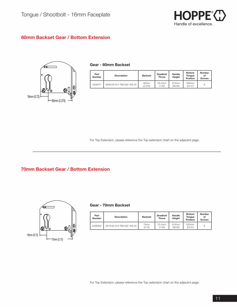
2406477 M/60/25 914 TNS 620 16S 20 60mm(2.375)
25.4mm(1.00)
914mm(36.00)
620mm(24.41) 6
Part Number Description Backset Deadbolt
ThrowHandle Height
Bottom Tongue Position
Number of
Screws
2406485 M/70/25 914 TNS 620 16S 20 70mm(2.75)
25.4mm(1.00)
914mm(36.00)
620mm(24.41) 6
For Top Extension, please reference the Top extension chart on the adjacent page.
For Top Extension, please reference the Top extension chart on the adjacent page.
Gear - 60mm Backset
Gear - 70mm Backset
70mm Backset Gear / Bottom Extension
60mm Backset Gear / Bottom Extension
70mm (2.75)18mm (0.72)
60mm (2.375)18mm (0.72)
12 Call 1-888-485-4885 www.us.hoppe.com
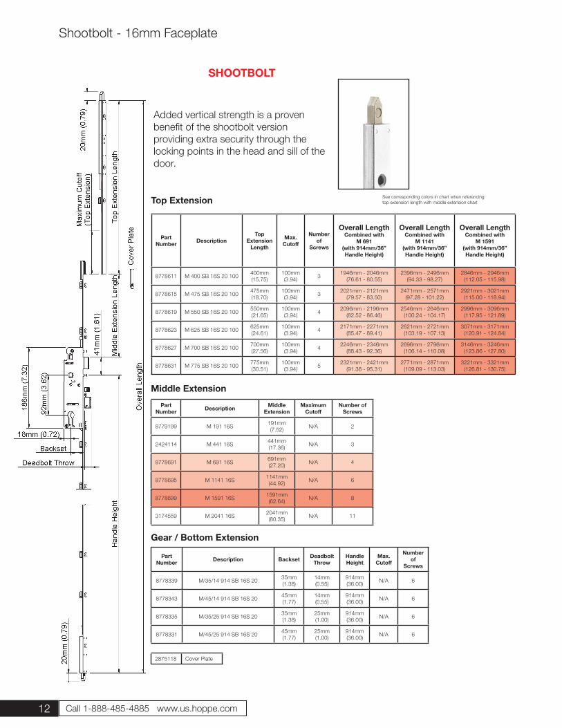
Added vertical strength is a proven benefit of the shootbolt version providing extra security through the locking points in the head and sill of the door.
SHOOTBOLT
Top Extension
Part Number Description
TopExtension
Length
Max. Cutoff
Number of
Screws
Overall Length Combined with
M 691(with 914mm/36” Handle Height)
Overall Length Combined with
M 1141(with 914mm/36” Handle Height)
Overall Length Combined with
M 1591(with 914mm/36” Handle Height)
8778611 M 400 SB 16S 20 100 400mm(15.75)
100mm(3.94) 3 1946mm - 2046mm
(76.61 - 80.55)2396mm - 2496mm
(94.33 - 98.27)2846mm - 2946mm
(112.05 - 115.98)
8778615 M 475 SB 16S 20 100 475mm(18.70)
100mm(3.94) 3 2021mm - 2121mm
(79.57 - 83.50)2471mm - 2571mm
(97.28 - 101.22)2921mm - 3021mm
(115.00 - 118.94)
8778619 M 550 SB 16S 20 100 550mm(21.65)
100mm(3.94) 4 2096mm - 2196mm
(82.52 - 86.46)2546mm - 2646mm
(100.24 - 104.17)2996mm - 3096mm
(117.95 - 121.89)
8778623 M 625 SB 16S 20 100 625mm(24.61)
100mm(3.94) 4 2171mm - 2271mm
(85.47 - 89.41)2621mm - 2721mm
(103.19 - 107.13)3071mm - 3171mm
(120.91 - 124.84)
8778627 M 700 SB 16S 20 100 700mm(27.56)
100mm(3.94) 4 2246mm - 2346mm
(88.43 - 92.36)2696mm - 2796mm
(106.14 - 110.08)3146mm - 3246mm
(123.86 - 127.80)
8778631 M 775 SB 16S 20 100 775mm(30.51)
100mm(3.94) 5 2321mm - 2421mm
(91.38 - 95.31)2771mm - 2871mm
(109.09 - 113.03)3221mm - 3321mm
(126.81 - 130.75)
Part Number Description Middle
ExtensionMaximum
CutoffNumber of
Screws
8779199 M 191 16S 191mm(7.52) N/A 2
2424114 M 441 16S 441mm(17.36) N/A 3
8778691 M 691 16S 691mm(27.20) N/A 4
8778695 M 1141 16S 1141mm(44.92) N/A 6
8778699 M 1591 16S 1591mm(62.64) N/A 8
3174559 M 2041 16S 2041mm(80.35) N/A 11
Part Number Description Backset Deadbolt
ThrowHandle Height
Max. Cutoff
Number of
Screws
8778339 M/35/14 914 SB 16S 20 35mm(1.38)
14mm(0.55)
914mm(36.00) N/A 6
8778343 M/45/14 914 SB 16S 20 45mm(1.77)
14mm(0.55)
914mm(36.00) N/A 6
8778335 M/35/25 914 SB 16S 20 35mm(1.38)
25mm(1.00)
914mm(36.00) N/A 6
8778331 M/45/25 914 SB 16S 20 45mm(1.77)
25mm(1.00)
914mm(36.00) N/A 6
Middle Extension
Gear / Bottom Extension
2875118 Cover Plate
Shootbolt - 16mm Faceplate
See corresponding colors in chart when referencingtop extension length with middle extension chart
13
Part Number Description Backset Deadbolt
ThrowHandle Height
Number of
Screws
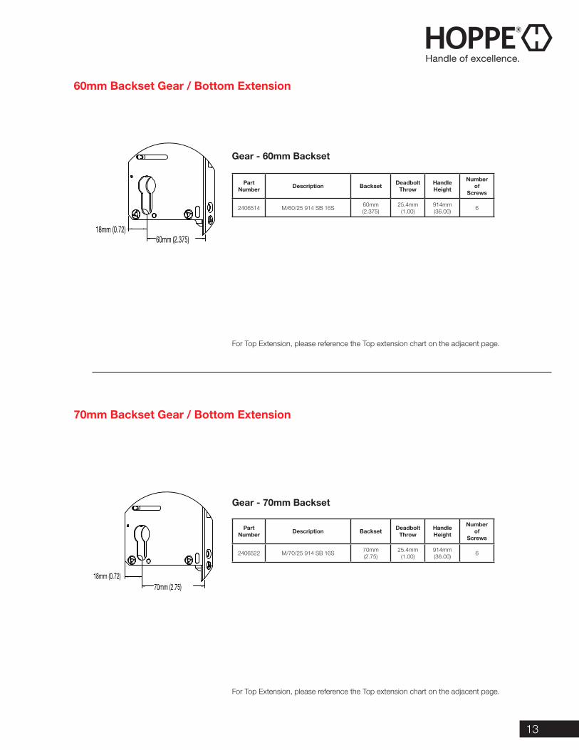
2406514 M/60/25 914 SB 16S 60mm(2.375)
25.4mm(1.00)
914mm(36.00) 6
Part Number Description Backset Deadbolt
ThrowHandle Height
Number of
Screws
2406522 M/70/25 914 SB 16S 70mm(2.75)
25.4mm(1.00)
914mm(36.00) 6
For Top Extension, please reference the Top extension chart on the adjacent page.
For Top Extension, please reference the Top extension chart on the adjacent page.
Gear - 70mm Backset
60mm Backset Gear / Bottom Extension
70mm Backset Gear / Bottom Extension
Gear - 60mm Backset
70mm (2.75)18mm (0.72)
60mm (2.375)18mm (0.72)
14 Call 1-888-485-4885 www.us.hoppe.com
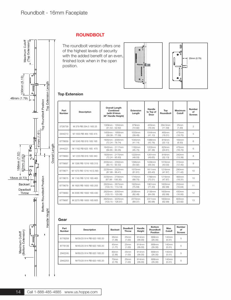
The roundbolt version offers one of the highest levels of security with the added benefit of an even, finished look when in the open position.
20mm (0.79)
ROUNDBOLT
Top Extension
Part Number Description
Overall Length Combined
(with 914mm 36” Handle Height)
Extension Length
Handle to Top of
Door
Top Roundbolt
MaximumCutoff
Number of
Screws
3726739 M 379 RB 294.5 16S 25 1309mm - 1334mm(51.53 - 52.62)
379mm(14.92)
420mm(16.54)
294.5mm(11.59)
25mm(1.00) 2
3444213 M 1003 RB 465 16S 475 1483mm - 1958mm(58.39 - 77.09)
1003mm(39.49)
1044mm(41.10)
465mm(18.31)
475mm(18.70) 5
8778659 M 1045 RB 816 16S 165 1835mm - 2000mm(72.24 - 78.74)
1045mm(41.14)
1086mm(42.76)
816mm(32.13)
165mm(6.50) 6
3444221 M 1162 RB 625 16S 475 1642mm - 2117mm(64.65 - 83.35)
1162mm(45.75)
1203mm(47.36)
625mm(24.61)
475mm(18.70) 6
8778663 M 1220 RB 816 16S 340 1835mm - 2175mm(72.24 - 85.63)
1220mm(48.03)
1261mm(49.65)
816mm(32.13)
340mm(13.39) 8
8778667 M 1395 RB 1016 16S 315 2035mm - 2350mm(80.15 - 92.52)
1395mm(54.92)
1436mm(56.54)
1016mm(40.00)
315mm(12.40) 9
8778671 M 1570 RB 1216 16 S 290 2235mm - 2525mm(87.99 - 99.41)
1570mm(61.81)
1611mm(63.43)
1216mm(47.87)
290mm(11.42) 10
8778675 M 1745 RB 1216 16S 465 2235mm - 2700mm(87.99 - 106.30)
1745mm(68.70)
1786mm(70.31)
1216mm(47.87)
465mm(18.31) 10
8778679 M 1920 RB 1600 16S 255 2620mm - 2875mm(103.15 - 113.19)
1920mm(75.59)
1961mm(77.20)
1600mm(62.99)
255mm(10.04) 11
8778683 M 2095 RB 1600 16S 430 2620mm - 3050mm(103.15 - 120.08)
2095mm(82.48)
2136mm(84.09)
1600mm(62.99)
430mm(16.93) 12
8778687 M 2270 RB 1600 16S 605 2620mm - 3225mm(103.15 - 126.97)
2270mm(89.37)
2311mm(90.98)
1600mm(62.99)
605mm(23.82) 13
Part Number Description Backset Deadbolt
ThrowHandle Height
Bottom Roundbolt Position
Max. Cutoff
Number of
Screws
8778259 M/35/25 914 RB 620 16S 20 35mm(1.38)
25mm(1.00)
914mm(36.00)
668mm(26.30)
140mm(5.51) 5
8778139 M/45/25 914 RB 620 16S 20 45mm(1.77)
25mm(1.00)
914mm(36.00)
668mm(26.30)
140mm(5.51) 5
2942245 M/60/25 914 RB 620 16S 20 60mm(2.36)
25mm(1.00)
914mm(36.00)
668mm(26.30)
140mm(5.51) 5
2942253 M/70/25 914 RB 620 16S 20 70mm(2.76)
25mm(1.00)
914mm(36.00)
668mm(26.30)
140mm(5.51) 5
Gear
Roundbolt - 16mm Faceplate
15
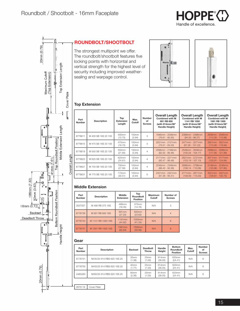
The strongest multipoint we offer. The roundbolt/shootbolt features five locking points with horizontal and vertical strength for the highest level of security including improved weather-sealing and warpage control.
ROUNDBOLT/SHOOTBOLT
Top Extension
Part Number Description
TopExtension
Length
Max. Cutoff
Number of
Screws
Overall Length Combined with M
691 RB 600(with 914mm/36” Handle Height)
Overall Length Combined with M
1141 RB 1050(with 914mm/36” Handle Height)
Overall Length Combined with M
1591 RB 1500(with 914mm/36” Handle Height)
8778611 M 400 SB 16S 20 100 400mm(15.75)
100mm(3.94) 3 1946mm - 2046mm
(76.61 - 80.55)2396mm - 2496mm
(94.33 - 98.27)2846mm - 2946mm
(112.05 - 115.98)
8778615 M 475 SB 16S 20 100 475mm(18.70)
100mm(3.94) 3 2021mm - 2121mm
(79.57 - 83.50)2471mm - 2571mm
(97.28 - 101.22)2921mm - 3021mm
(115.00 - 118.94)
8778619 M 550 SB 16S 20 100 550mm(21.65)
100mm(3.94) 4 2096mm - 2196mm
(82.52 - 86.46)2546mm - 2646mm
(100.24 - 104.17)2996mm - 3096mm
(117.95 - 121.89)
8778623 M 625 SB 16S 20 100 625mm(24.61)
100mm(3.94) 4 2171mm - 2271mm
(85.47 - 86.46)2621mm - 2721mm
(103.19 - 107.13)3071mm - 3171mm
(120.91 - 124.84)
8778627 M 700 SB 16S 20 100 700mm(27.56)
100mm(3.94) 4 2246mm - 2346mm
(88.43 - 92.36)2696mm - 2796mm
(106.14 - 110.08)3146mm - 3246mm
(123.86 - 127.80)
8778631 M 775 SB 16S 20 100 775mm(30.51)
100mm(3.94) 5 2321mm - 2421mm
(91.38 - 95.31)2771mm - 2871mm
(109.09 - 113.03)3221mm - 3321mm
(126.81 - 130.75)
Part Number Description Middle
Extension
Top Roundbolt Position
Maximum Cutoff
Number of Screws
3537057 M 466 RB 375 16S 466mm(18.35)
375mm(14.76) N/A 3
8778739 M 691 RB 600 16S 691mm(27.20)
600mm(23.62) N/A 4
8778743 M 1141 RB 1050 16S 1141mm(44.92)
1050mm(41.34) N/A 6
8778747 M 1591 RB 1500 16S 1591mm(62.64)
1500mm(59.06) N/A 8
Part Number Description Backset Deadbolt
ThrowHandle Height
Bottom Roundbolt Position
Max. Cutoff
Number of
Screws
8778751 M/35/25 914 RBS 620 16S 20 35mm(1.38)
25mm(1.00)
914mm(36.00)
620mm(24.41) N/A 6
8778755 M/45/25 914 RBS 620 16S 20 45mm(1.77)
25mm(1.00)
914mm(36.00)
620mm(24.41) N/A 6
2485283 M/60/25 914 RBS 620 16S 20 60mm(2.36)
25mm(1.00)
914mm(36.00)
620mm(24.41) N/A 6
Middle Extension
Gear
2875118 Cover Plate
Roundbolt / Shootbolt - 16mm Faceplate
16 Call 1-888-485-4885 www.us.hoppe.com
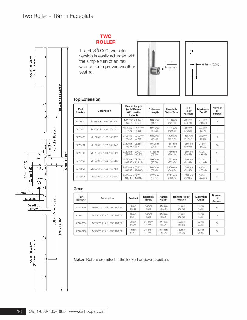
8.7mm (0.34)
The HLS®9000 two roller version is easily adjusted with the simple turn of an hex wrench for improved weather sealing.
TWO ROLLER
Part Number Description
Overall Length(with 914mm36” Handle
Height)
Extension Length
Handle to Top of Door
Top Roller
Position
Maximum Cutoff
Numberof
Screws
8778479 M 1045 RL 730 16S 275 1725mm-2000mm(67.91 - 78.74)
1045mm(41.14)
1086mm(42.76)
730mm(28.74)
275mm(10.83) 7
8778483 M 1220 RL 930 16S 250 1925mm - 2175mm(75.79 - 85.63)
1220mm(48.03)
1261mm(49.65)
930mm(36.61)
250mm(9.84) 8
8778487 M 1395 RL 1135 16S 220 2130mm - 2350mm(83.86 - 92.52)
1395mm(54.92)
1436mm(56.54)
1135mm(44.69)
220mm(8.66) 9
8778491 M 1570 RL 1285 16S 245 2280mm - 2525mm(89.76 - 99.41)
1570mm(61.81)
1611mm(63.43)
1285mm(50.59)
245mm(9.65) 10
8778495 M 1745 RL 1285 16S 420 2280mm - 2700mm(89.76 - 106.30)
1745mm(68.70)
1786mm(70.31)
1285mm(50.59)
420mm(16.54) 11
8778499 M 1920 RL 1600 16S 280 2595mm - 2875mm(102.17 - 113.19)
1920mm(75.59)
1961mm(77.20)
1600mm(62.99)
280mm(11.02) 11
8778503 M 2095 RL 1600 16S 455 2595mm - 3050mm(102.17 - 120.08)
2095mm(82.48)
2136mm(84.09)
1600mm(62.99)
455mm(17.91) 12
8778507 M 2270 RL 1600 16S 630 2595mm - 3225mm(102.17 - 126.97)
2270mm(89.37)
2311mm(90.98)
1600mm(62.99)
630mm(24.80) 13
Part Number Description Backset Deadbolt
ThrowHandle Height
Bottom RollerPosition
Maximum Cutoff
Number of
Screws
8778279 M/35/14 914 RL 750 16S 60 35mm(1.38)
14mm(.55)
914mm(36.00)
750mm(29.53)
60mm(2.36) 5
8778511 M/45/14 914 RL 750 16S 60 45mm(1.77)
14mm(.55)
914mm(36.00)
750mm(29.53)
60mm(2.36) 5
8778255 M/35/25 914 RL 750 16S 60 35mm(1.38)
25.4mm(1.00)
914mm(36.00)
750mm(29.53)
60mm(2.36) 5
8778223 M/45/25 914 RL 750 16S 60 45mm(1.77)
25.4mm(1.00)
914mm(36.00)
750mm(29.65)
60mm(2.36) 5
Gear
Top Extension
Two Roller - 16mm Faceplate
+1mm
Adjustment
Note: Rollers are listed in the locked or down position.
17
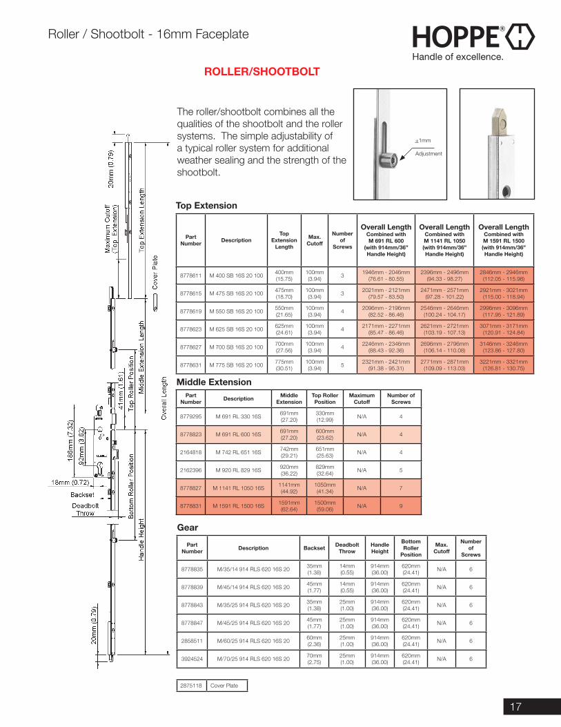
The roller/shootbolt combines all the qualities of the shootbolt and the roller systems. The simple adjustability of a typical roller system for additional weather sealing and the strength of the shootbolt.
ROLLER/SHOOTBOLT
Top Extension
Part Number Description
TopExtension
Length
Max. Cutoff
Number of
Screws
Overall Length Combined with M 691 RL 600
(with 914mm/36” Handle Height)
Overall Length Combined with M 1141 RL 1050(with 914mm/36” Handle Height)
Overall Length Combined with M 1591 RL 1500(with 914mm/36” Handle Height)
8778611 M 400 SB 16S 20 100 400mm(15.75)
100mm(3.94) 3 1946mm - 2046mm
(76.61 - 80.55)2396mm - 2496mm
(94.33 - 98.27)2846mm - 2946mm
(112.05 - 115.98)
8778615 M 475 SB 16S 20 100 475mm(18.70)
100mm(3.94) 3 2021mm - 2121mm
(79.57 - 83.50)2471mm - 2571mm
(97.28 - 101.22)2921mm - 3021mm
(115.00 - 118.94)
8778619 M 550 SB 16S 20 100 550mm(21.65)
100mm(3.94) 4 2096mm - 2196mm
(82.52 - 86.46)2546mm - 2646mm
(100.24 - 104.17)2996mm - 3096mm
(117.95 - 121.89)
8778623 M 625 SB 16S 20 100 625mm(24.61)
100mm(3.94) 4 2171mm - 2271mm
(85.47 - 86.46)2621mm - 2721mm
(103.19 - 107.13)3071mm - 3171mm
(120.91 - 124.84)
8778627 M 700 SB 16S 20 100 700mm(27.56)
100mm(3.94) 4 2246mm - 2346mm
(88.43 - 92.36)2696mm - 2796mm
(106.14 - 110.08)3146mm - 3246mm
(123.86 - 127.80)
8778631 M 775 SB 16S 20 100 775mm(30.51)
100mm(3.94) 5 2321mm - 2421mm
(91.38 - 95.31)2771mm - 2871mm
(109.09 - 113.03)3221mm - 3321mm
(126.81 - 130.75)
Part Number Description Middle
ExtensionTop Roller Position
Maximum Cutoff
Number of Screws
8779295 M 691 RL 330 16S 691mm(27.20)
330mm(12.99) N/A 4
8778823 M 691 RL 600 16S 691mm(27.20)
600mm(23.62) N/A 4
2164818 M 742 RL 651 16S 742mm(29.21)
651mm(25.63) N/A 4
2162396 M 920 RL 829 16S 920mm(36.22)
829mm(32.64) N/A 5
8778827 M 1141 RL 1050 16S 1141mm(44.92)
1050mm(41.34) N/A 7
8778831 M 1591 RL 1500 16S 1591mm(62.64)
1500mm(59.06) N/A 9
Part Number Description Backset Deadbolt
ThrowHandle Height
Bottom Roller
Position
Max. Cutoff
Number of
Screws
8778835 M/35/14 914 RLS 620 16S 20 35mm(1.38)
14mm(0.55)
914mm(36.00)
620mm(24.41) N/A 6
8778839 M/45/14 914 RLS 620 16S 20 45mm(1.77)
14mm(0.55)
914mm(36.00)
620mm(24.41) N/A 6
8778843 M/35/25 914 RLS 620 16S 20 35mm(1.38)
25mm(1.00)
914mm(36.00)
620mm(24.41) N/A 6
8778847 M/45/25 914 RLS 620 16S 20 45mm(1.77)
25mm(1.00)
914mm(36.00)
620mm(24.41) N/A 6
2858511 M/60/25 914 RLS 620 16S 20 60mm(2.36)
25mm(1.00)
914mm(36.00)
620mm(24.41) N/A 6
3924524 M/70/25 914 RLS 620 16S 20 70mm(2.75)
25mm(1.00)
914mm(36.00)
620mm(24.41) N/A 6
Middle Extension
Gear
2875118 Cover Plate
+1mm
Adjustment
Roller / Shootbolt - 16mm Faceplate
18 Call 1-888-485-4885 www.us.hoppe.com
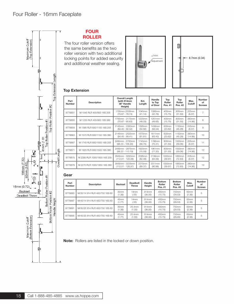
The four roller version offers the same benefits as the two roller version with two additional locking points for added security and additional weather sealing.
FOUR ROLLER
Part Number Description Backset Deadbolt
ThrowHandle Height
Bottom Roller
Pos. #1
Bottom Roller
Pos. #2
Max. Cutoff
Number of
Screws
8778883 M/35/14 914 RLR 400/750 16S 60 35mm(1.38)
14mm(.55)
914mm(36.00)
400mm(15.75)
750mm(29.53)
60mm(2.36) 5
8778887 M/45/14 914 RLR 400/750 16S 60 45mm(1.77)
14mm(.55)
914mm(36.00)
400mm(15.75)
750mm(29.53)
60mm(2.36) 5
8778891 M/35/25 914 RLR 400/750 16S 60 35mm(1.38)
25.4mm(1.00)
914mm(36.00)
400mm(15.75)
750mm(29.53)
60mm(2.36) 5
8778895 M/45/25 914 RLR 400/750 16S 60 45mm(1.77)
25.4mm(1.00)
914mm(36.00)
400mm(15.75)
750mm(29.65)
60mm(2.36) 5
Gear
Top Extension
Four Roller - 16mm Faceplate
+1mm
Adjustment
Part Number Description
Overall Length(with 914mm36” Handle
Height)
Ext. Length
Handle to Top
of Door
Top Roller
Pos. #1
Top Roller
Pos. #2
Max. Cutoff
Numberof
Screws
8778851 M 1045 RLR 400/800 16S 205 1795mm-2000mm(70.67 - 78.74)
1045mm(41.14)
1086mm(42.76)
400mm(15.75)
800mm(31.50)
205mm(8.07) 7
8778855 M 1220 RLR 400/800 16S 380 1795mm - 2175mm(70.67 - 85.63)
1220mm(48.03)
1261mm(49.65)
400mm(15.75)
800mm(31.50)
380mm(14.96) 8
8778859 M 1395 RLR 600/1150 16S 205 2145mm - 2350mm(84.45 - 92.52)
1395mm(54.92)
1436mm(56.54)
600mm(23.62)
1150mm(45.28)
205mm(8.07) 9
8778863 M 1570 RLR 600/1150 16S 380 2145mm - 2525mm(84.45 - 99.41)
1570mm(61.81)
1611mm(63.43)
600mm(23.62)
1150mm(45.28)
380mm(14.96) 10
8778867 M 1745 RLR 800/1500 16S 205 2495mm - 2700mm(98.23 - 106.30)
1745mm(68.70)
1786mm(70.31)
800mm(31.50)
1500mm(59.06)
205mm(8.07) 11
8778871 M 1920 RLR 800/1500 16S 380 2495mm - 2875mm(98.23 - 113.19)
1920mm(75.59)
1961mm(77.20)
800mm(31.50)
1500mm(59.06)
380mm(14.96) 12
8778875 M 2095 RLR 1000/1850 16S 205 2845mm - 3050mm(112.01 - 120.08)
2095mm(82.48)
2136mm(84.09)
1000mm(39.97)
1850mm(72.83)
205mm(8.07) 12
8778879 M 2270 RLR 1000/1850 16S 380 2845mm - 3225mm(112.01 - 126.97)
2270mm(89.37)
2311mm(90.98)
1000mm(39.97)
1850mm(72.83)
380mm(14.96) 13
Note: Rollers are listed in the locked or down position.
8.7mm (0.34)
19
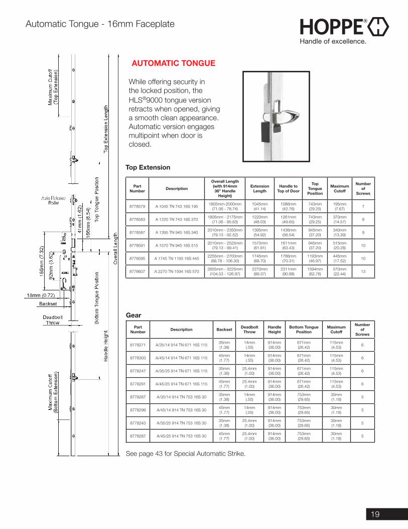
While offering security in the locked position, the HLS®9000 tongue version retracts when opened, giving a smooth clean appearance. Automatic version engages multipoint when door is closed.
AUTOMATIC TONGUE
Part Number Description
Overall Length(with 914mm36” Handle
Height)
Extension Length
Handle to Top of Door
Top Tongue Position
Maximum Cutoff
Numberof
Screws
8778579 A 1045 TN 743 16S 195 1805mm-2000mm(71.06 - 78.74)
1045mm(41.14)
1086mm(42.76)
743mm(29.25)
195mm(7.67) 7
8778583 A 1220 TN 743 16S 370 1805mm - 2175mm(71.06 - 85.63)
1220mm(48.03)
1261mm(49.65)
743mm(29.25)
370mm(14.57) 8
8778587 A 1395 TN 945 16S 340 2010mm - 2350mm(79.13 - 92.52)
1395mm(54.92)
1436mm(56.54)
945mm(37.20)
340mm(13.39) 9
8778591 A 1570 TN 945 16S 515 2010mm - 2525mm(79.13 - 99.41)
1570mm(61.81)
1611mm(63.43)
945mm(37.20)
515mm(20.28) 10
8778595 A 1745 TN 1193 16S 445 2255mm - 2700mm(88.78 - 106.30)
1745mm(68.70)
1786mm(70.31)
1193mm(46.97)
445mm(17.52) 10
8778607 A 2270 TN 1594 16S 570 2655mm - 3225mm(104.53 - 126.97)
2270mm(89.37)
2311mm(90.98)
1594mm(62.76)
570mm(22.44) 13
Part Number Description Backset Deadbolt
ThrowHandle Height
Bottom Tongue Position
Maximum Cutoff
Number of
Screws
8778271 A/35/14 914 TN 671 16S 115 35mm(1.38)
14mm(.55)
914mm(36.00)
671mm(26.42)
115mm(4.53) 6
8778303 A/45/14 914 TN 671 16S 115 45mm(1.77)
14mm(.55)
914mm(36.00)
671mm(26.42)
115mm(4.53) 6
8778247 A/35/25 914 TN 671 16S 115 35mm(1.38)
25.4mm(1.00)
914mm(36.00)
671mm(26.42)
115mm(4.53) 6
8778291 A/45/25 914 TN 671 16S 115 45mm(1.77)
25.4mm(1.00)
914mm(36.00)
671mm(26.42)
115mm(4.53) 6
8778267 A/35/14 914 TN 753 16S 30 35mm(1.38)
14mm(.55)
914mm(36.00)
753mm(29.65)
30mm(1.18) 5
8778299 A/45/14 914 TN 753 16S 30 45mm(1.77)
14mm(.55)
914mm(36.00)
753mm(29.65)
30mm(1.18) 5
8778243 A/35/25 914 TN 753 16S 30 35mm(1.38)
25.4mm(1.00)
914mm(36.00)
753mm(29.65)
30mm(1.18) 5
8778287 A/45/25 914 TN 753 16S 30 45mm(1.77)
25.4mm(1.00)
914mm(36.00)
753mm(29.65)
30mm(1.18) 5
Gear
Top Extension
Automatic Tongue - 16mm Faceplate
See page 43 for Special Automatic Strike.
20 Call 1-888-485-4885 www.us.hoppe.com
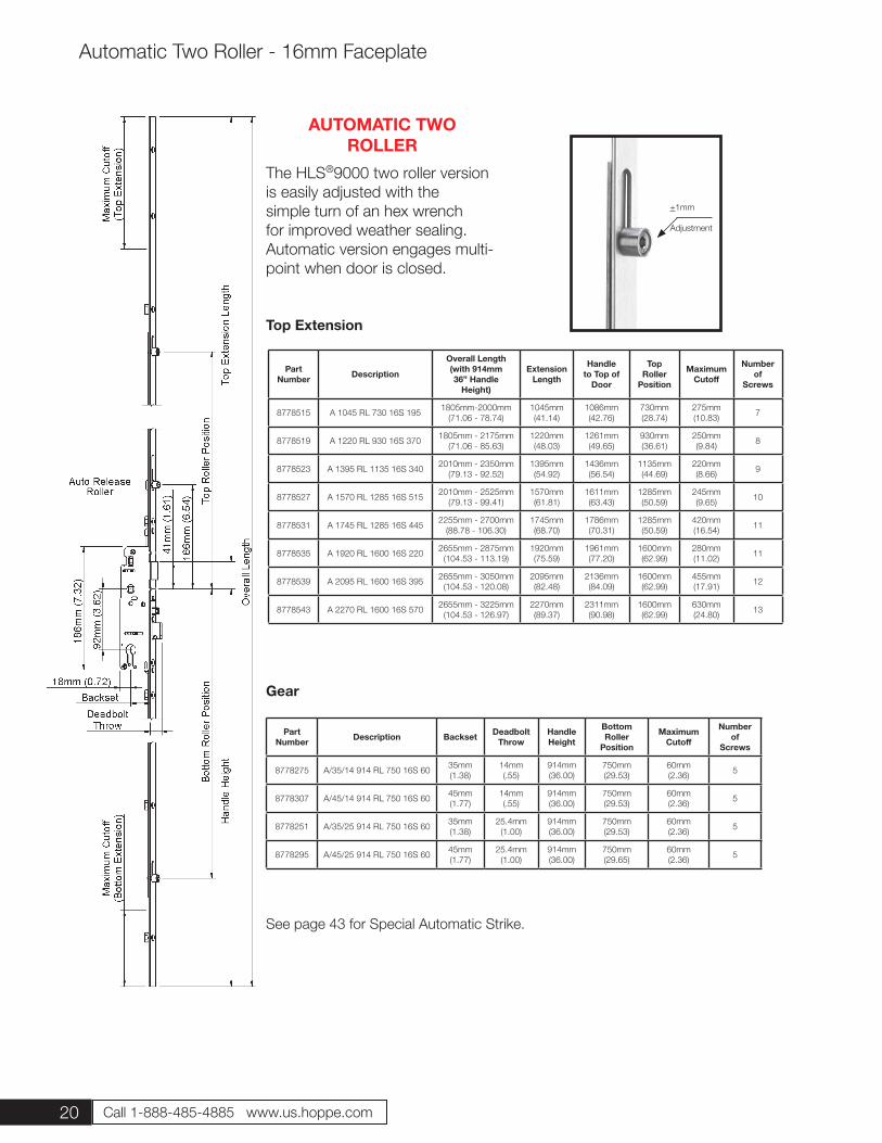
The HLS®9000 two roller version is easily adjusted with the simple turn of an hex wrench for improved weather sealing. Automatic version engages multi-point when door is closed.
AUTOMATIC TWO ROLLER
Part Number Description
Overall Length(with 914mm36” Handle
Height)
Extension Length
Handle to Top of
Door
Top Roller
Position
Maximum Cutoff
Numberof
Screws
8778515 A 1045 RL 730 16S 195 1805mm-2000mm(71.06 - 78.74)
1045mm(41.14)
1086mm(42.76)
730mm(28.74)
275mm(10.83) 7
8778519 A 1220 RL 930 16S 370 1805mm - 2175mm(71.06 - 85.63)
1220mm(48.03)
1261mm(49.65)
930mm(36.61)
250mm(9.84) 8
8778523 A 1395 RL 1135 16S 340 2010mm - 2350mm(79.13 - 92.52)
1395mm(54.92)
1436mm(56.54)
1135mm(44.69)
220mm(8.66) 9
8778527 A 1570 RL 1285 16S 515 2010mm - 2525mm(79.13 - 99.41)
1570mm(61.81)
1611mm(63.43)
1285mm(50.59)
245mm(9.65) 10
8778531 A 1745 RL 1285 16S 445 2255mm - 2700mm(88.78 - 106.30)
1745mm(68.70)
1786mm(70.31)
1285mm(50.59)
420mm(16.54) 11
8778535 A 1920 RL 1600 16S 220 2655mm - 2875mm(104.53 - 113.19)
1920mm(75.59)
1961mm(77.20)
1600mm(62.99)
280mm(11.02) 11
8778539 A 2095 RL 1600 16S 395 2655mm - 3050mm(104.53 - 120.08)
2095mm(82.48)
2136mm(84.09)
1600mm(62.99)
455mm(17.91) 12
8778543 A 2270 RL 1600 16S 570 2655mm - 3225mm(104.53 - 126.97)
2270mm(89.37)
2311mm(90.98)
1600mm(62.99)
630mm(24.80) 13
Part Number Description Backset Deadbolt
ThrowHandle Height
Bottom Roller
Position
Maximum Cutoff
Number of
Screws
8778275 A/35/14 914 RL 750 16S 60 35mm(1.38)
14mm(.55)
914mm(36.00)
750mm(29.53)
60mm(2.36) 5
8778307 A/45/14 914 RL 750 16S 60 45mm(1.77)
14mm(.55)
914mm(36.00)
750mm(29.53)
60mm(2.36) 5
8778251 A/35/25 914 RL 750 16S 60 35mm(1.38)
25.4mm(1.00)
914mm(36.00)
750mm(29.53)
60mm(2.36) 5
8778295 A/45/25 914 RL 750 16S 60 45mm(1.77)
25.4mm(1.00)
914mm(36.00)
750mm(29.65)
60mm(2.36) 5
Gear
Top Extension
Automatic Two Roller - 16mm Faceplate
+1mm
Adjustment
See page 43 for Special Automatic Strike.
21
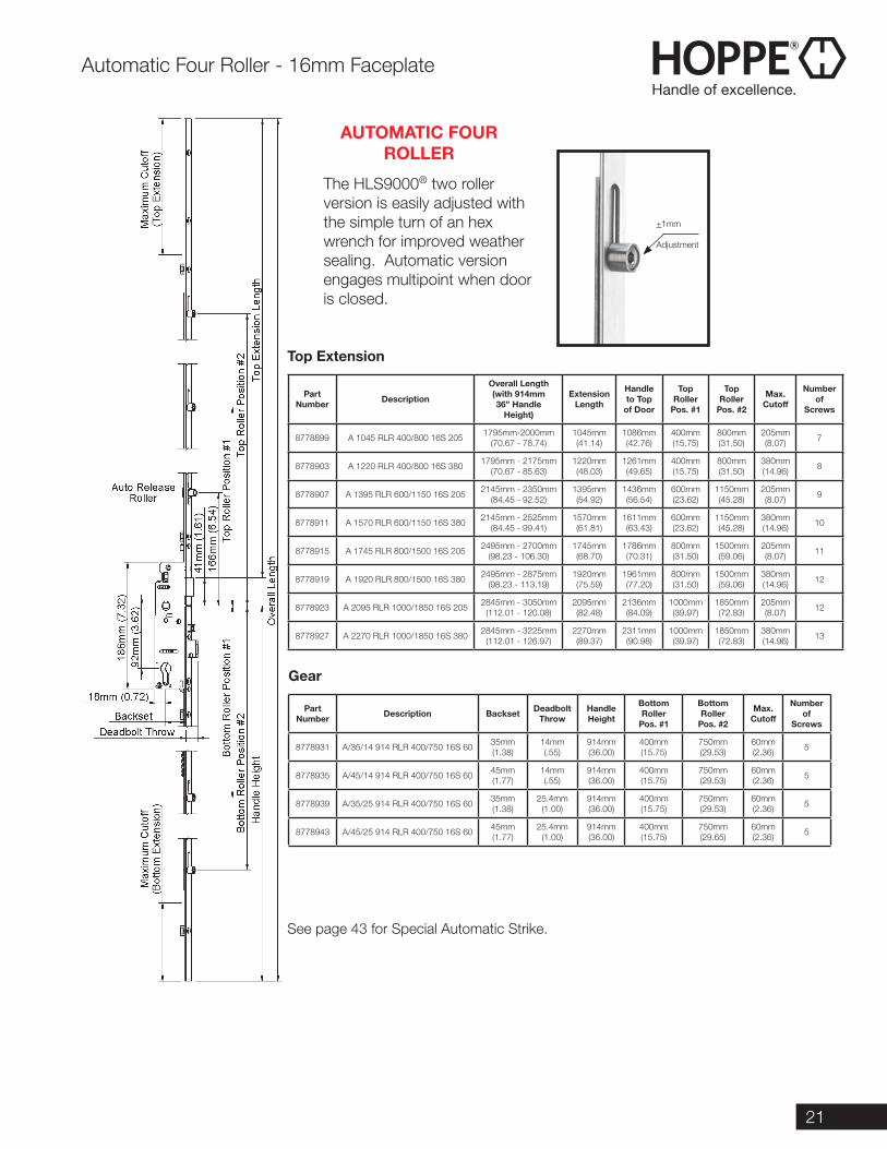
The HLS9000® two roller version is easily adjusted with the simple turn of an hex wrench for improved weather sealing. Automatic version engages multipoint when door is closed.
AUTOMATIC FOUR ROLLER
Part Number Description
Overall Length(with 914mm36” Handle
Height)
Extension Length
Handle to Top
of Door
Top Roller
Pos. #1
Top Roller
Pos. #2
Max. Cutoff
Numberof
Screws
8778899 A 1045 RLR 400/800 16S 205 1795mm-2000mm(70.67 - 78.74)
1045mm(41.14)
1086mm(42.76)
400mm(15.75)
800mm(31.50)
205mm(8.07) 7
8778903 A 1220 RLR 400/800 16S 380 1795mm - 2175mm(70.67 - 85.63)
1220mm(48.03)
1261mm(49.65)
400mm(15.75)
800mm(31.50)
380mm(14.96) 8
8778907 A 1395 RLR 600/1150 16S 205 2145mm - 2350mm(84.45 - 92.52)
1395mm(54.92)
1436mm(56.54)
600mm(23.62)
1150mm(45.28)
205mm(8.07) 9
8778911 A 1570 RLR 600/1150 16S 380 2145mm - 2525mm(84.45 - 99.41)
1570mm(61.81)
1611mm(63.43)
600mm(23.62)
1150mm(45.28)
380mm(14.96) 10
8778915 A 1745 RLR 800/1500 16S 205 2495mm - 2700mm(98.23 - 106.30)
1745mm(68.70)
1786mm(70.31)
800mm(31.50)
1500mm(59.06)
205mm(8.07) 11
8778919 A 1920 RLR 800/1500 16S 380 2495mm - 2875mm(98.23 - 113.19)
1920mm(75.59)
1961mm(77.20)
800mm(31.50)
1500mm(59.06)
380mm(14.96) 12
8778923 A 2095 RLR 1000/1850 16S 205 2845mm - 3050mm(112.01 - 120.08)
2095mm(82.48)
2136mm(84.09)
1000mm(39.97)
1850mm(72.83)
205mm(8.07) 12
8778927 A 2270 RLR 1000/1850 16S 380 2845mm - 3225mm(112.01 - 126.97)
2270mm(89.37)
2311mm(90.98)
1000mm(39.97)
1850mm(72.83)
380mm(14.96) 13
Part Number Description Backset Deadbolt
ThrowHandle Height
Bottom Roller
Pos. #1
Bottom Roller
Pos. #2
Max. Cutoff
Number of
Screws
8778931 A/35/14 914 RLR 400/750 16S 60 35mm(1.38)
14mm(.55)
914mm(36.00)
400mm(15.75)
750mm(29.53)
60mm(2.36) 5
8778935 A/45/14 914 RLR 400/750 16S 60 45mm(1.77)
14mm(.55)
914mm(36.00)
400mm(15.75)
750mm(29.53)
60mm(2.36) 5
8778939 A/35/25 914 RLR 400/750 16S 60 35mm(1.38)
25.4mm(1.00)
914mm(36.00)
400mm(15.75)
750mm(29.53)
60mm(2.36) 5
8778943 A/45/25 914 RLR 400/750 16S 60 45mm(1.77)
25.4mm(1.00)
914mm(36.00)
400mm(15.75)
750mm(29.65)
60mm(2.36) 5
Gear
Top Extension
Automatic Four Roller - 16mm Faceplate
+1mm
Adjustment
See page 43 for Special Automatic Strike.
22 Call 1-888-485-4885 www.us.hoppe.com
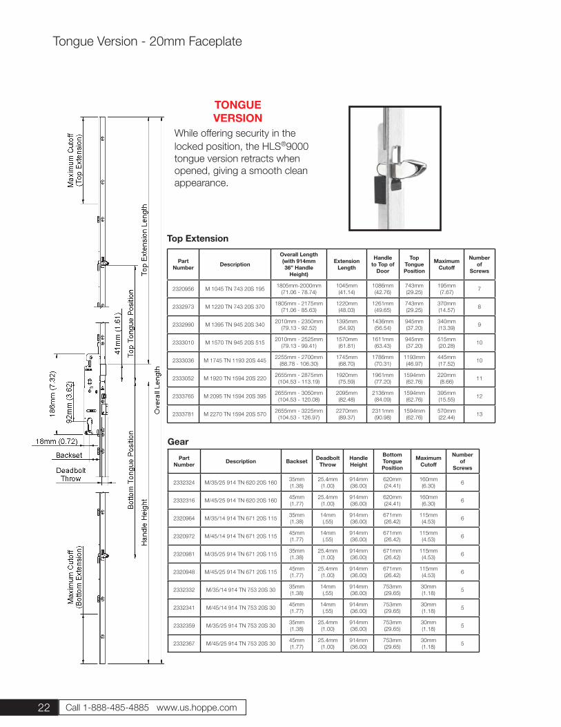
While offering security in the locked position, the HLS®9000 tongue version retracts when opened, giving a smooth clean appearance.
TONGUE VERSION
Part Number Description
Overall Length(with 914mm36” Handle
Height)
Extension Length
Handle to Top of
Door
Top Tongue Position
Maximum Cutoff
Numberof
Screws
2320956 M 1045 TN 743 20S 195 1805mm-2000mm(71.06 - 78.74)
1045mm(41.14)
1086mm(42.76)
743mm(29.25)
195mm(7.67) 7
2332973 M 1220 TN 743 20S 370 1805mm - 2175mm(71.06 - 85.63)
1220mm(48.03)
1261mm(49.65)
743mm(29.25)
370mm(14.57) 8
2332990 M 1395 TN 945 20S 340 2010mm - 2350mm(79.13 - 92.52)
1395mm(54.92)
1436mm(56.54)
945mm(37.20)
340mm(13.39) 9
2333010 M 1570 TN 945 20S 515 2010mm - 2525mm(79.13 - 99.41)
1570mm(61.81)
1611mm(63.43)
945mm(37.20)
515mm(20.28) 10
2333036 M 1745 TN 1193 20S 445 2255mm - 2700mm(88.78 - 106.30)
1745mm(68.70)
1786mm(70.31)
1193mm(46.97)
445mm(17.52) 10
2333052 M 1920 TN 1594 20S 220 2655mm - 2875mm(104.53 - 113.19)
1920mm(75.59)
1961mm(77.20)
1594mm(62.76)
220mm(8.66) 11
2333765 M 2095 TN 1594 20S 395 2655mm - 3050mm(104.53 - 120.08)
2095mm(82.48)
2136mm(84.09)
1594mm(62.76)
395mm(15.55) 12
2333781 M 2270 TN 1594 20S 570 2655mm - 3225mm(104.53 - 126.97)
2270mm(89.37)
2311mm(90.98)
1594mm(62.76)
570mm(22.44) 13
Part Number Description Backset Deadbolt
ThrowHandle Height
Bottom Tongue Position
Maximum Cutoff
Number of
Screws
2332324 M/35/25 914 TN 620 20S 160 35mm(1.38)
25.4mm(1.00)
914mm(36.00)
620mm(24.41)
160mm(6.30) 6
2332316 M/45/25 914 TN 620 20S 160 45mm(1.77)
25.4mm(1.00)
914mm(36.00)
620mm(24.41)
160mm(6.30) 6
2320964 M/35/14 914 TN 671 20S 115 35mm(1.38)
14mm(.55)
914mm(36.00)
671mm(26.42)
115mm(4.53) 6
2320972 M/45/14 914 TN 671 20S 115 45mm(1.77)
14mm(.55)
914mm(36.00)
671mm(26.42)
115mm(4.53) 6
2320981 M/35/25 914 TN 671 20S 115 35mm(1.38)
25.4mm(1.00)
914mm(36.00)
671mm(26.42)
115mm(4.53) 6
2320948 M/45/25 914 TN 671 20S 115 45mm(1.77)
25.4mm(1.00)
914mm(36.00)
671mm(26.42)
115mm(4.53) 6
2332332 M/35/14 914 TN 753 20S 30 35mm(1.38)
14mm(.55)
914mm(36.00)
753mm(29.65)
30mm(1.18) 5
2332341 M/45/14 914 TN 753 20S 30 45mm(1.77)
14mm(.55)
914mm(36.00)
753mm(29.65)
30mm(1.18) 5
2332359 M/35/25 914 TN 753 20S 30 35mm(1.38)
25.4mm(1.00)
914mm(36.00)
753mm(29.65)
30mm(1.18) 5
2332367 M/45/25 914 TN 753 20S 30 45mm(1.77)
25.4mm(1.00)
914mm(36.00)
753mm(29.65)
30mm(1.18) 5
Gear
Top Extension
Tongue Version - 20mm Faceplate
23
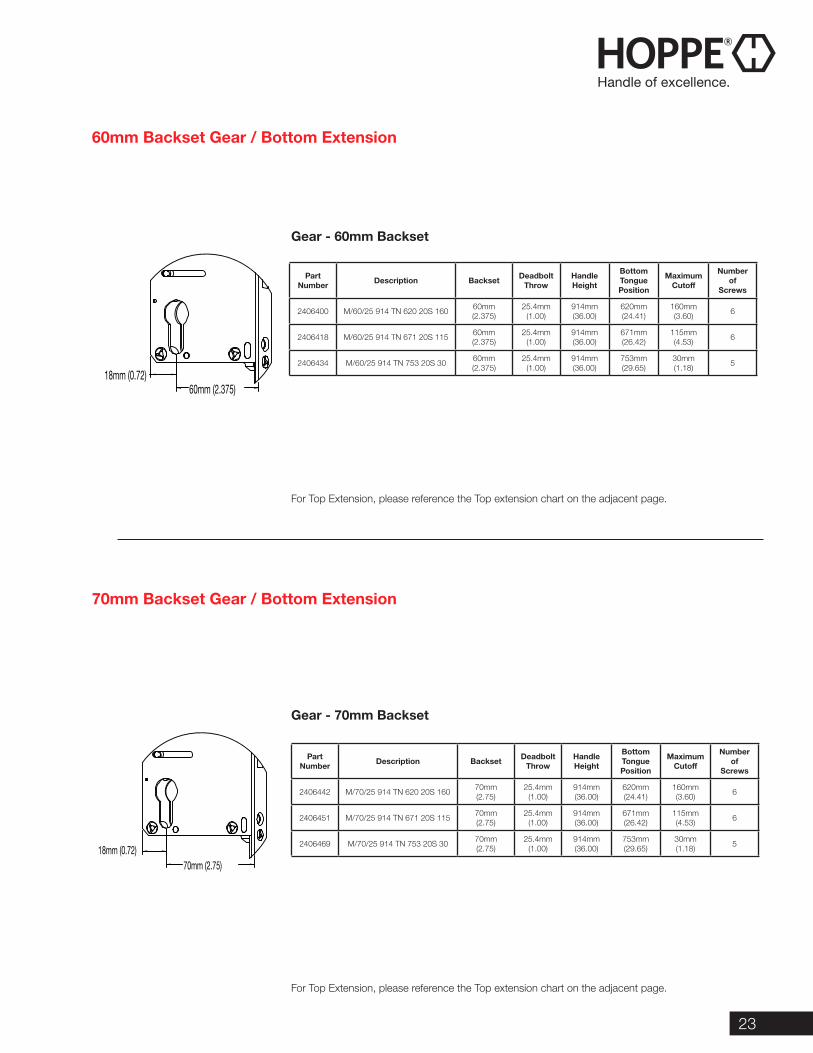
Part Number Description Backset Deadbolt
ThrowHandle Height
Bottom Tongue Position
Maximum Cutoff
Number of
Screws
2406400 M/60/25 914 TN 620 20S 160 60mm(2.375)
25.4mm(1.00)
914mm(36.00)
620mm(24.41)
160mm(3.60) 6
2406418 M/60/25 914 TN 671 20S 115 60mm(2.375)
25.4mm(1.00)
914mm(36.00)
671mm(26.42)
115mm(4.53) 6
2406434 M/60/25 914 TN 753 20S 30 60mm(2.375)
25.4mm(1.00)
914mm(36.00)
753mm(29.65)
30mm(1.18) 5
Part Number Description Backset Deadbolt
ThrowHandle Height
Bottom Tongue Position
Maximum Cutoff
Number of
Screws
2406442 M/70/25 914 TN 620 20S 160 70mm(2.75)
25.4mm(1.00)
914mm(36.00)
620mm(24.41)
160mm(3.60) 6
2406451 M/70/25 914 TN 671 20S 115 70mm(2.75)
25.4mm(1.00)
914mm(36.00)
671mm(26.42)
115mm(4.53) 6
2406469 M/70/25 914 TN 753 20S 30 70mm(2.75)
25.4mm(1.00)
914mm(36.00)
753mm(29.65)
30mm(1.18) 5
For Top Extension, please reference the Top extension chart on the adjacent page.
For Top Extension, please reference the Top extension chart on the adjacent page.
Gear - 60mm Backset
Gear - 70mm Backset
60mm Backset Gear / Bottom Extension
70mm Backset Gear / Bottom Extension
70mm (2.75)18mm (0.72)
60mm (2.375)18mm (0.72)
24 Call 1-888-485-4885 www.us.hoppe.com
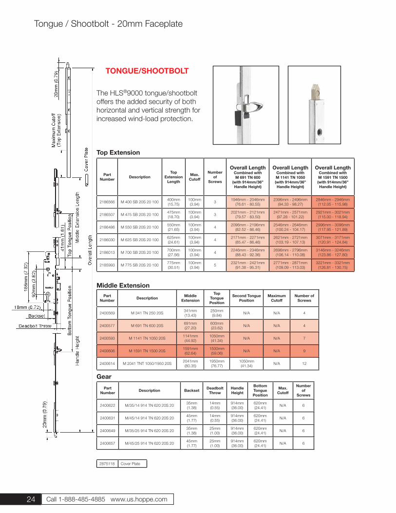
The HLS®9000 tongue/shootbolt offers the added security of both horizontal and vertical strength for increased wind-load protection.
TONGUE/SHOOTBOLT
Top Extension
Part Number Description
TopExtension
Length
Max. Cutoff
Number of
Screws
Overall Length Combined with M 691 TN 600
(with 914mm/36” Handle Height)
Overall Length Combined with M 1141 TN 1050(with 914mm/36” Handle Height)
Overall Length Combined with M 1591 TN 1500(with 914mm/36” Handle Height)
2186566 M 400 SB 20S 20 100 400mm(15.75)
100mm(3.94) 3 1946mm - 2046mm
(76.61 - 80.55)2396mm - 2496mm
(94.33 - 98.27)2846mm - 2946mm
(112.05 - 115.98)
2186507 M 475 SB 20S 20 100 475mm(18.70)
100mm(3.94) 3 2021mm - 2121mm
(79.57 - 83.50)2471mm - 2571mm
(97.28 - 101.22)2921mm - 3021mm
(115.00 - 118.94)
2186486 M 550 SB 20S 20 100 550mm(21.65)
100mm(3.94) 4 2096mm - 2196mm
(82.52 - 86.46)2546mm - 2646mm
(100.24 - 104.17)2996mm - 3096mm
(117.95 - 121.89)
2186030 M 625 SB 20S 20 100 625mm(24.61)
100mm(3.94) 4 2171mm - 2271mm
(85.47 - 86.46)2621mm - 2721mm
(103.19 - 107.13)3071mm - 3171mm
(120.91 - 124.84)
2186013 M 700 SB 20S 20 100 700mm(27.56)
100mm(3.94) 4 2246mm - 2346mm
(88.43 - 92.36)2696mm - 2796mm
(106.14 - 110.08)3146mm - 3246mm
(123.86 - 127.80)
2185993 M 775 SB 20S 20 100 775mm(30.51)
100mm(3.94) 5 2321mm - 2421mm
(91.38 - 95.31)2771mm - 2871mm
(109.09 - 113.03)3221mm - 3321mm
(126.81 - 130.75)
Part Number Description Middle
Extension
Top Tongue Position
Second Tongue Position
Maximum Cutoff
Number of Screws
2400569 M 341 TN 250 20S 341mm(13.43)
250mm(9.84) N/A N/A 4
2400577 M 691 TN 600 20S 691mm(27.20)
600mm(23.62) N/A N/A 4
2400593 M 1141 TN 1050 20S 1141mm(44.92)
1050mm(41.34) N/A N/A 7
2400606 M 1591 TN 1500 20S 1591mm(62.64)
1500mm(59.06) N/A N/A 9
2400614 M 2041 TNT 1050/1950 20S 2041mm(80.35)
1950mm(76.77)
1050mm(41.34) N/A 12
Part Number Description Backset Deadbolt
ThrowHandle Height
Bottom Tongue Position
Max. Cutoff
Number of
Screws
2400622 M/35/14 914 TN 620 20S 20 35mm(1.38)
14mm(0.55)
914mm(36.00)
620mm(24.41) N/A 6
2400631 M/45/14 914 TN 620 20S 20 45mm(1.77)
14mm(0.55)
914mm(36.00)
620mm(24.41) N/A 6
2400649 M/35/25 914 TN 620 20S 20 35mm(1.38)
25mm(1.00)
914mm(36.00)
620mm(24.41) N/A 6
2400657 M/45/25 914 TN 620 20S 20 45mm(1.77)
25mm(1.00)
914mm(36.00)
620mm(24.41) N/A 6
Middle Extension
Gear
2875118 Cover Plate
Tongue / Shootbolt - 20mm Faceplate
25
Part Number Description Backset Deadbolt
ThrowHandle Height
Bottom Tongue Position
Number of
Screws
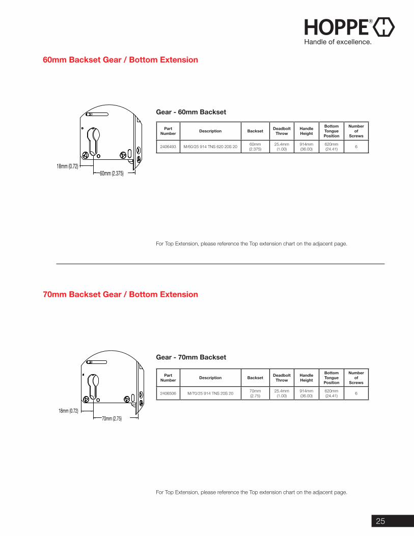
2406493 M/60/25 914 TNS 620 20S 20 60mm(2.375)
25.4mm(1.00)
914mm(36.00)
620mm(24.41) 6
Part Number Description Backset Deadbolt
ThrowHandle Height
Bottom Tongue Position
Number of
Screws
2406506 M/70/25 914 TNS 20S 20 70mm(2.75)
25.4mm(1.00)
914mm(36.00)
620mm(24.41) 6
For Top Extension, please reference the Top extension chart on the adjacent page.
For Top Extension, please reference the Top extension chart on the adjacent page.
Gear - 60mm Backset
Gear - 70mm Backset
60mm Backset Gear / Bottom Extension
70mm Backset Gear / Bottom Extension
70mm (2.75)18mm (0.72)
60mm (2.375)18mm (0.72)
26 Call 1-888-485-4885 www.us.hoppe.com
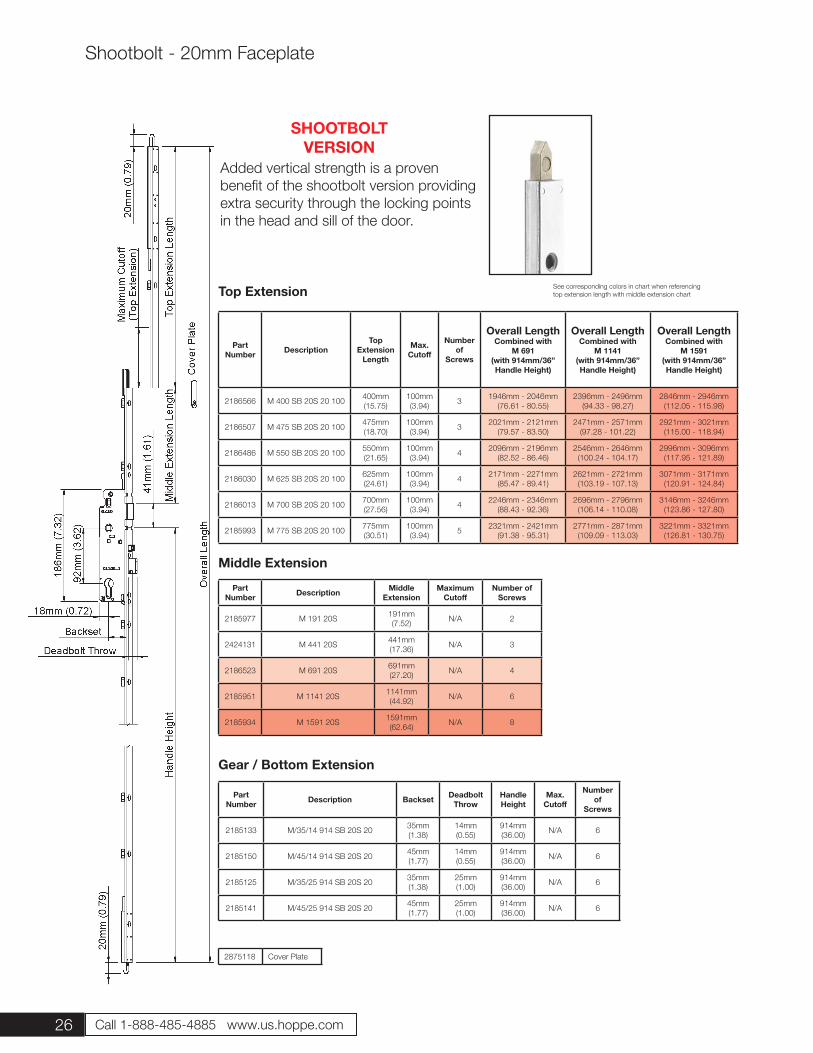
Added vertical strength is a proven benefit of the shootbolt version providing extra security through the locking points in the head and sill of the door.
SHOOTBOLTVERSION
Top Extension
Part Number Description
TopExtension
Length
Max. Cutoff
Number of
Screws
Overall Length Combined with
M 691(with 914mm/36” Handle Height)
Overall Length Combined with
M 1141(with 914mm/36” Handle Height)
Overall Length Combined with
M 1591(with 914mm/36” Handle Height)
2186566 M 400 SB 20S 20 100 400mm(15.75)
100mm(3.94) 3 1946mm - 2046mm
(76.61 - 80.55)2396mm - 2496mm
(94.33 - 98.27)2846mm - 2946mm
(112.05 - 115.98)
2186507 M 475 SB 20S 20 100 475mm(18.70)
100mm(3.94) 3 2021mm - 2121mm
(79.57 - 83.50)2471mm - 2571mm
(97.28 - 101.22)2921mm - 3021mm
(115.00 - 118.94)
2186486 M 550 SB 20S 20 100 550mm(21.65)
100mm(3.94) 4 2096mm - 2196mm
(82.52 - 86.46)2546mm - 2646mm
(100.24 - 104.17)2996mm - 3096mm
(117.95 - 121.89)
2186030 M 625 SB 20S 20 100 625mm(24.61)
100mm(3.94) 4 2171mm - 2271mm
(85.47 - 89.41)2621mm - 2721mm
(103.19 - 107.13)3071mm - 3171mm
(120.91 - 124.84)
2186013 M 700 SB 20S 20 100 700mm(27.56)
100mm(3.94) 4 2246mm - 2346mm
(88.43 - 92.36)2696mm - 2796mm
(106.14 - 110.08)3146mm - 3246mm
(123.86 - 127.80)
2185993 M 775 SB 20S 20 100 775mm(30.51)
100mm(3.94) 5 2321mm - 2421mm
(91.38 - 95.31)2771mm - 2871mm
(109.09 - 113.03)3221mm - 3321mm
(126.81 - 130.75)
Part Number Description Middle
ExtensionMaximum
CutoffNumber of
Screws
2185977 M 191 20S 191mm(7.52) N/A 2
2424131 M 441 20S 441mm(17.36) N/A 3
2186523 M 691 20S 691mm(27.20) N/A 4
2185951 M 1141 20S 1141mm(44.92) N/A 6
2185934 M 1591 20S 1591mm(62.64) N/A 8
Part Number Description Backset Deadbolt
ThrowHandle Height
Max. Cutoff
Number of
Screws
2185133 M/35/14 914 SB 20S 20 35mm(1.38)
14mm(0.55)
914mm(36.00) N/A 6
2185150 M/45/14 914 SB 20S 20 45mm(1.77)
14mm(0.55)
914mm(36.00) N/A 6
2185125 M/35/25 914 SB 20S 20 35mm(1.38)
25mm(1.00)
914mm(36.00) N/A 6
2185141 M/45/25 914 SB 20S 20 45mm(1.77)
25mm(1.00)
914mm(36.00) N/A 6
Middle Extension
Gear / Bottom Extension
2875118 Cover Plate
Shootbolt - 20mm Faceplate
See corresponding colors in chart when referencingtop extension length with middle extension chart
27
Part Number Description Backset Deadbolt
ThrowHandle Height
Number of
Screws
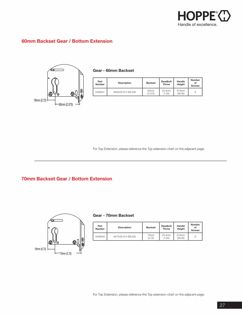
2406531 M/60/25 914 SB 20S 60mm(2.375)
25.4mm(1.00)
914mm(36.00) 6
Part Number Description Backset Deadbolt
ThrowHandle Height
Number of
Screws
2406549 M/70/25 914 SB 20S 70mm(2.75)
25.4mm(1.00)
914mm(36.00) 6
For Top Extension, please reference the Top extension chart on the adjacent page.
For Top Extension, please reference the Top extension chart on the adjacent page.
Gear - 70mm Backset
60mm Backset Gear / Bottom Extension
70mm Backset Gear / Bottom Extension
Gear - 60mm Backset
70mm (2.75)18mm (0.72)
60mm (2.375)18mm (0.72)
28 Call 1-888-485-4885 www.us.hoppe.com
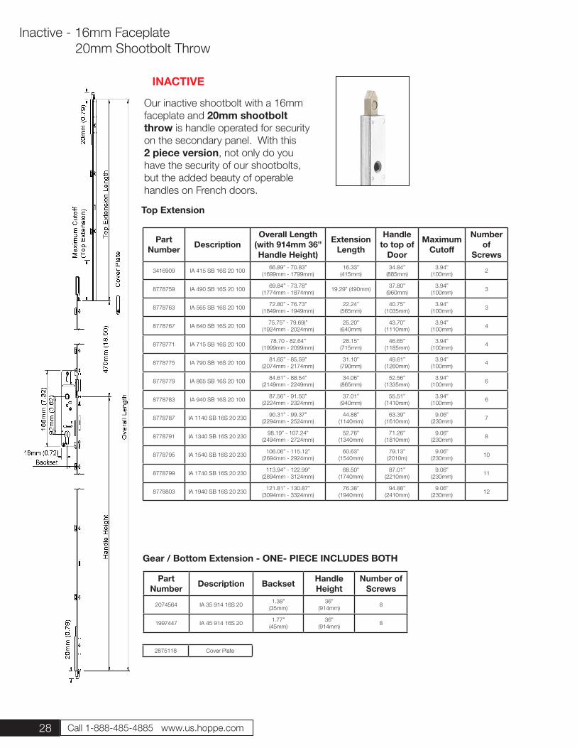
Our inactive shootbolt with a 16mm faceplate and 20mm shootbolt throw is handle operated for security on the secondary panel. With this 2 piece version, not only do you have the security of our shootbolts, but the added beauty of operable handles on French doors.
Part Number Description Backset Handle
HeightNumber of
Screws
2074564 IA 35 914 16S 20 1.38”(35mm)
36”(914mm) 8
1997447 IA 45 914 16S 20 1.77”(45mm)
36”(914mm) 8
Gear / Bottom Extension - ONE- PIECE INCLUDES BOTH
Top Extension
2875118 Cover Plate
Inactive - 16mm Faceplate 20mm Shootbolt Throw
Part Number Description
Overall Length (with 914mm 36” Handle Height)
Extension Length
Handle to top of
Door
Maximum Cutoff
Number of
Screws
3416909 IA 415 SB 16S 20 100 66.89” - 70.83”(1699mm - 1799mm)
16.33”(415mm)
34.84”(885mm)
3.94”(100mm) 2
8778759 IA 490 SB 16S 20 100 69.84” - 73.78”(1774mm - 1874mm) 19.29” (490mm) 37.80”
(960mm)3.94”
(100mm) 3
8778763 IA 565 SB 16S 20 100 72.80” - 76.73” (1849mm - 1949mm)
22.24”(565mm)
40.75”(1035mm)
3.94” (100mm) 3
8778767 IA 640 SB 16S 20 100 75.75” - 79.69)”(1924mm - 2024mm)
25.20”(640mm)
43.70”(1110mm)
3.94” (100mm) 4
8778771 IA 715 SB 16S 20 100 78.70 - 82.64”(1999mm - 2099mm)
28.15”(715mm)
46.65”(1185mm)
3.94” (100mm) 4
8778775 IA 790 SB 16S 20 100 81.65” - 85.59”(2074mm - 2174mm)
31.10”(790mm)
49.61”(1260mm)
3.94” (100mm) 4
8778779 IA 865 SB 16S 20 100 84.61” - 88.54” (2149mm - 2249mm)
34.06”(865mm)
52.56”(1335mm)
3.94” (100mm) 6
8778783 IA 940 SB 16S 20 100 87.56” - 91.50”(2224mm - 2324mm)
37.01”(940mm)
55.51”(1410mm)
3.94” (100mm) 6
8778787 IA 1140 SB 16S 20 230 90.31” - 99.37”(2294mm - 2524mm)
44.88”(1140mm)
63.39”(1610mm)
9.06”(230mm) 7
8778791 IA 1340 SB 16S 20 230 98.19” - 107.24”(2494mm - 2724mm)
52.76”(1340mm)
71.26”(1810mm)
9.06”(230mm) 8
8778795 IA 1540 SB 16S 20 230 106.06” - 115.12” (2694mm - 2924mm)
60.63”(1540mm)
79.13”(2010m)
9.06”(230mm) 10
8778799 IA 1740 SB 16S 20 230 113.94” - 122.99” (2894mm - 3124mm)
68.50”(1740mm)
87.01”(2210mm)
9.06”(230mm) 11
8778803 IA 1940 SB 16S 20 230 121.81” - 130.87”(3094mm - 3324mm)
76.38”(1940mm)
94.88”(2410mm)
9.06”(230mm) 12
INACTIVE
29
Inactive - 16mm Faceplate 20mm Shootbolt Throw
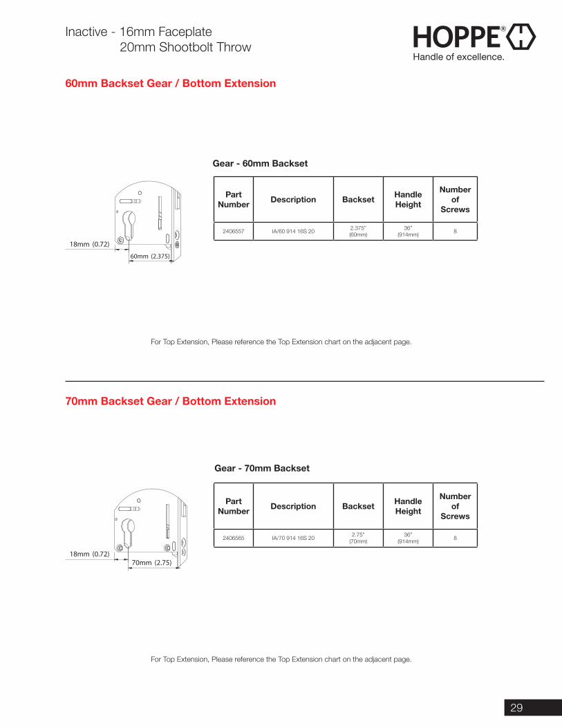
60mm Backset Gear / Bottom Extension
For Top Extension, Please reference the Top Extension chart on the adjacent page.
For Top Extension, Please reference the Top Extension chart on the adjacent page.
70mm Backset Gear / Bottom Extension
60mm (2.375)
18mm (0.72)
70mm (2.75)18mm (0.72)
Part Number Description Backset Handle
Height
Number of
Screws
2406557 IA/60 914 16S 20 2.375”(60mm)
36”(914mm) 8
Part Number Description Backset Handle
Height
Number of
Screws
2406565 IA/70 914 16S 20 2.75”(70mm)
36”(914mm) 8
Gear - 60mm Backset
Gear - 70mm Backset
30 Call 1-888-485-4885 www.us.hoppe.com
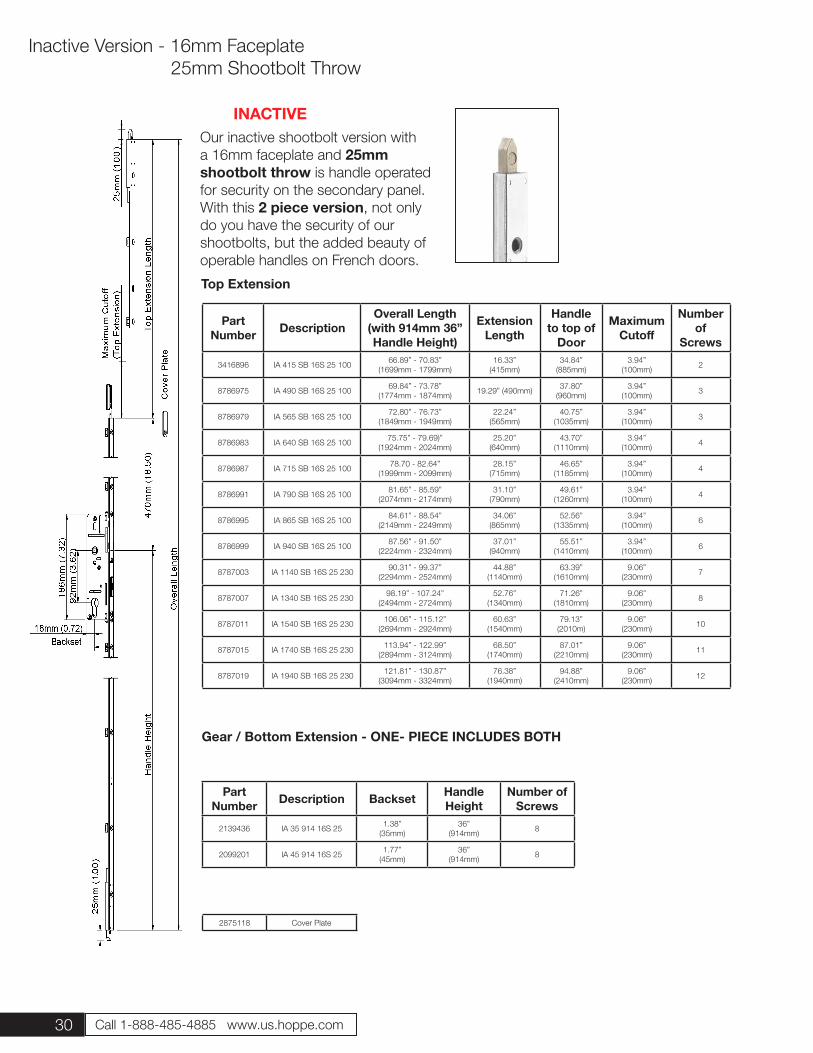
Our inactive shootbolt version with a 16mm faceplate and 25mm shootbolt throw is handle operated for security on the secondary panel. With this 2 piece version, not only do you have the security of our shootbolts, but the added beauty of operable handles on French doors.
Part Number Description
Overall Length (with 914mm 36” Handle Height)
Extension Length
Handle to top of
Door
Maximum Cutoff
Number of
Screws
3416896 IA 415 SB 16S 25 100 66.89” - 70.83”(1699mm - 1799mm)
16.33”(415mm)
34.84”(885mm)
3.94”(100mm) 2
8786975 IA 490 SB 16S 25 100 69.84” - 73.78”(1774mm - 1874mm) 19.29” (490mm) 37.80”
(960mm)3.94”
(100mm) 3
8786979 IA 565 SB 16S 25 100 72.80” - 76.73” (1849mm - 1949mm)
22.24”(565mm)
40.75”(1035mm)
3.94” (100mm) 3
8786983 IA 640 SB 16S 25 100 75.75” - 79.69)”(1924mm - 2024mm)
25.20”(640mm)
43.70”(1110mm)
3.94” (100mm) 4
8786987 IA 715 SB 16S 25 100 78.70 - 82.64”(1999mm - 2099mm)
28.15”(715mm)
46.65”(1185mm)
3.94” (100mm) 4
8786991 IA 790 SB 16S 25 100 81.65” - 85.59”(2074mm - 2174mm)
31.10”(790mm)
49.61”(1260mm)
3.94” (100mm) 4
8786995 IA 865 SB 16S 25 100 84.61” - 88.54” (2149mm - 2249mm)
34.06”(865mm)
52.56”(1335mm)
3.94” (100mm) 6
8786999 IA 940 SB 16S 25 100 87.56” - 91.50”(2224mm - 2324mm)
37.01”(940mm)
55.51”(1410mm)
3.94” (100mm) 6
8787003 IA 1140 SB 16S 25 230 90.31” - 99.37”(2294mm - 2524mm)
44.88”(1140mm)
63.39”(1610mm)
9.06”(230mm) 7
8787007 IA 1340 SB 16S 25 230 98.19” - 107.24”(2494mm - 2724mm)
52.76”(1340mm)
71.26”(1810mm)
9.06”(230mm) 8
8787011 IA 1540 SB 16S 25 230 106.06” - 115.12” (2694mm - 2924mm)
60.63”(1540mm)
79.13”(2010m)
9.06”(230mm) 10
8787015 IA 1740 SB 16S 25 230 113.94” - 122.99” (2894mm - 3124mm)
68.50”(1740mm)
87.01”(2210mm)
9.06”(230mm) 11
8787019 IA 1940 SB 16S 25 230 121.81” - 130.87”(3094mm - 3324mm)
76.38”(1940mm)
94.88”(2410mm)
9.06”(230mm) 12
Top Extension
2875118 Cover Plate
Inactive Version - 16mm Faceplate 25mm Shootbolt Throw
Part Number Description Backset Handle
HeightNumber of
Screws
2139436 IA 35 914 16S 25 1.38”(35mm)
36”(914mm) 8
2099201 IA 45 914 16S 25 1.77”(45mm)
36”(914mm) 8
Gear / Bottom Extension - ONE- PIECE INCLUDES BOTH
INACTIVE
31
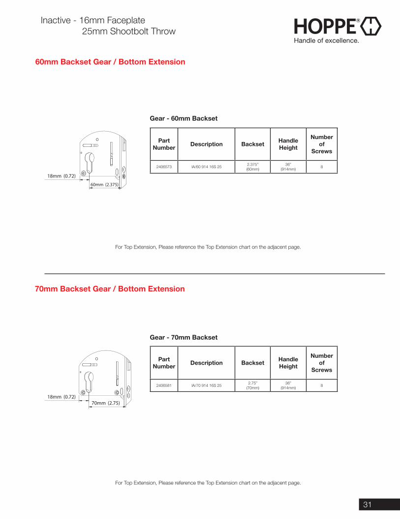
Inactive - 16mm Faceplate 25mm Shootbolt Throw
60mm Backset Gear / Bottom Extension
For Top Extension, Please reference the Top Extension chart on the adjacent page.
For Top Extension, Please reference the Top Extension chart on the adjacent page.
70mm Backset Gear / Bottom Extension
60mm (2.375)
18mm (0.72)
70mm (2.75)18mm (0.72)
Part Number Description Backset Handle
Height
Number of
Screws
2406573 IA/60 914 16S 25 2.375”(60mm)
36”(914mm) 8
Part Number Description Backset Handle
Height
Number of
Screws
2406581 IA/70 914 16S 25 2.75”(70mm)
36”(914mm) 8
Gear - 60mm Backset
Gear - 70mm Backset
32 Call 1-888-485-4885 www.us.hoppe.com
Inactive - 16mm Faceplate 20mm Shootbolt Throw
Part Number Description
Overall Length (with 914mm 36” Handle Height)
Extension Length
Handle to top of
Door
Maximum Cutoff
Number of
Screws
3416909 IA 415 SB 16S 20 100 66.89” - 70.83”(1699mm - 1799mm)
16.33”(415mm)
34.84”(885mm)
3.94”(100mm) 2
8778759 IA 490 SB 16S 20 100 69.84” - 73.78”(1774mm - 1874mm) 19.29” (490mm) 37.80”
(960mm)3.94”
(100mm) 3
8778763 IA 565 SB 16S 20 100 72.80” - 76.73” (1849mm - 1949mm)
22.24”(565mm)
40.75”(1035mm)
3.94” (100mm) 3
8778767 IA 640 SB 16S 20 100 75.75” - 79.69)”(1924mm - 2024mm)
25.20”(640mm)
43.70”(1110mm)
3.94” (100mm) 4
8778771 IA 715 SB 16S 20 100 78.70 - 82.64”(1999mm - 2099mm)
28.15”(715mm)
46.65”(1185mm)
3.94” (100mm) 4
8778775 IA 790 SB 16S 20 100 81.65” - 85.59”(2074mm - 2174mm)
31.10”(790mm)
49.61”(1260mm)
3.94” (100mm) 4
8778779 IA 865 SB 16S 20 100 84.61” - 88.54” (2149mm - 2249mm)
34.06”(865mm)
52.56”(1335mm)
3.94” (100mm) 6
8778783 IA 940 SB 16S 20 100 87.56” - 91.50”(2224mm - 2324mm)
37.01”(940mm)
55.51”(1410mm)
3.94” (100mm) 6
8778787 IA 1140 SB 16S 20 230 90.31” - 99.37”(2294mm - 2524mm)
44.88”(1140mm)
63.39”(1610mm)
9.06”(230mm) 7
8778791 IA 1340 SB 16S 20 230 98.19” - 107.24”(2494mm - 2724mm)
52.76”(1340mm)
71.26”(1810mm)
9.06”(230mm) 8
8778795 IA 1540 SB 16S 20 230 106.06” - 115.12” (2694mm - 2924mm)
60.63”(1540mm)
79.13”(2010m)
9.06”(230mm) 10
8778799 IA 1740 SB 16S 20 230 113.94” - 122.99” (2894mm - 3124mm)
68.50”(1740mm)
87.01”(2210mm)
9.06”(230mm) 11
8778803 IA 1940 SB 16S 20 230 121.81” - 130.87”(3094mm - 3324mm)
76.38”(1940mm)
94.88”(2410mm)
9.06”(230mm) 12
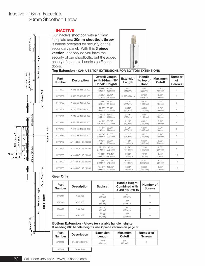
Our inactive shootbolt with a 16mm faceplate and 20mm shootbolt throw is handle operated for security on the secondary panel. With this 3 piece version, not only do you have the security of our shootbolts, but the added beauty of operable handles on French doors.
Part Number Description Backset
Handle Height Combined with IA 434 16S 20 15
Number of Screws
8778155 IA 35 16S 1.38”(35mm)
36”(914mm) 6
8778443 IA 45 16S 1.77”(45mm)
36”(914mm) 6
3403999 IA 60 16S 2.375”(60mm)
36”(914mm) 6
3761139 IA 70 16S 2.755” (70mm)
36”(914mm) 6
Gear Only
Top Extension - CAN USE TOP EXTENSIONS FOR BOTTOM EXTENSIONS
Part Number Description Extension
LengthMaximum
CutoffNumber of
Screws
8787583 IA 434 16S 20 15 17.09”(434mm)
.59”(15mm) 3
Bottom Extension - Allows for variable handle heights If needing 36” handle heights use 2 piece version on page 30
2875118 Cover Plate
INACTIVE
33
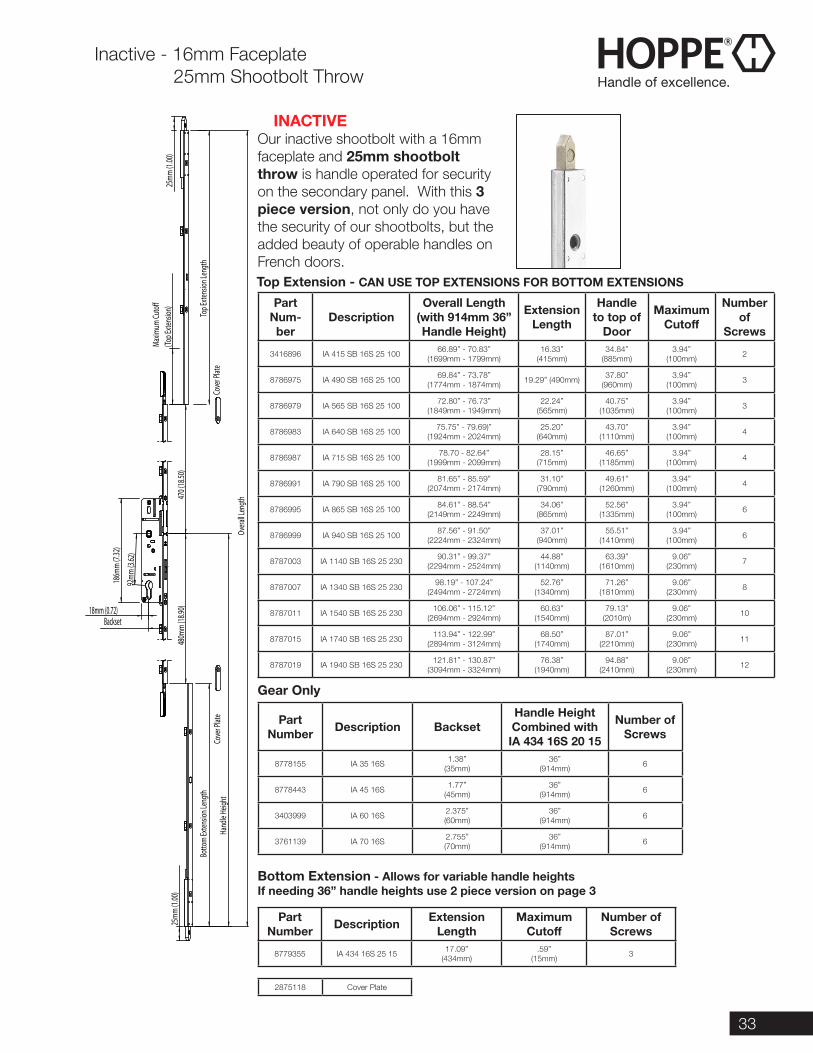
INACTIVEOur inactive shootbolt with a 16mm faceplate and 25mm shootbolt throw is handle operated for security on the secondary panel. With this 3 piece version, not only do you have the security of our shootbolts, but the added beauty of operable handles on French doors.
(Top E
xtens
ion)
Maxim
um Cu
to�
25mm
(1.00
)
92mm
(3.62
)
Hand
le He
ight
25mm
(1.00
)
Top E
xtens
ion Le
ngth
470 (
18.50
)48
0mm
(18.90
)
Botto
m Ex
tensio
n Len
gth
186m
m (7.
32)
18mm (0.72)Backset
Overa
ll Len
gth
Cove
r Plat
eCo
ver P
late
Part Num-ber
DescriptionOverall Length
(with 914mm 36” Handle Height)
Extension Length
Handle to top of
Door
Maximum Cutoff
Number of
Screws
3416896 IA 415 SB 16S 25 100 66.89” - 70.83”(1699mm - 1799mm)
16.33”(415mm)
34.84”(885mm)
3.94”(100mm) 2
8786975 IA 490 SB 16S 25 100 69.84” - 73.78”(1774mm - 1874mm) 19.29” (490mm) 37.80”
(960mm)3.94”
(100mm) 3
8786979 IA 565 SB 16S 25 100 72.80” - 76.73” (1849mm - 1949mm)
22.24”(565mm)
40.75”(1035mm)
3.94” (100mm) 3
8786983 IA 640 SB 16S 25 100 75.75” - 79.69)”(1924mm - 2024mm)
25.20”(640mm)
43.70”(1110mm)
3.94” (100mm) 4
8786987 IA 715 SB 16S 25 100 78.70 - 82.64”(1999mm - 2099mm)
28.15”(715mm)
46.65”(1185mm)
3.94” (100mm) 4
8786991 IA 790 SB 16S 25 100 81.65” - 85.59”(2074mm - 2174mm)
31.10”(790mm)
49.61”(1260mm)
3.94” (100mm) 4
8786995 IA 865 SB 16S 25 100 84.61” - 88.54” (2149mm - 2249mm)
34.06”(865mm)
52.56”(1335mm)
3.94” (100mm) 6
8786999 IA 940 SB 16S 25 100 87.56” - 91.50”(2224mm - 2324mm)
37.01”(940mm)
55.51”(1410mm)
3.94” (100mm) 6
8787003 IA 1140 SB 16S 25 230 90.31” - 99.37”(2294mm - 2524mm)
44.88”(1140mm)
63.39”(1610mm)
9.06”(230mm) 7
8787007 IA 1340 SB 16S 25 230 98.19” - 107.24”(2494mm - 2724mm)
52.76”(1340mm)
71.26”(1810mm)
9.06”(230mm) 8
8787011 IA 1540 SB 16S 25 230 106.06” - 115.12” (2694mm - 2924mm)
60.63”(1540mm)
79.13”(2010m)
9.06”(230mm) 10
8787015 IA 1740 SB 16S 25 230 113.94” - 122.99” (2894mm - 3124mm)
68.50”(1740mm)
87.01”(2210mm)
9.06”(230mm) 11
8787019 IA 1940 SB 16S 25 230 121.81” - 130.87”(3094mm - 3324mm)
76.38”(1940mm)
94.88”(2410mm)
9.06”(230mm) 12
Part Number Description Backset
Handle Height Combined with IA 434 16S 20 15
Number of Screws
8778155 IA 35 16S 1.38”(35mm)
36”(914mm) 6
8778443 IA 45 16S 1.77”(45mm)
36”(914mm) 6
3403999 IA 60 16S 2.375”(60mm)
36”(914mm) 6
3761139 IA 70 16S 2.755” (70mm)
36”(914mm) 6
Gear Only
Top Extension - CAN USE TOP EXTENSIONS FOR BOTTOM EXTENSIONS
Part Number Description Extension
LengthMaximum
CutoffNumber of
Screws
8779355 IA 434 16S 25 15 17.09”(434mm)
.59”(15mm) 3
Bottom Extension - Allows for variable handle heights If needing 36” handle heights use 2 piece version on page 3
2875118 Cover Plate
Inactive - 16mm Faceplate 25mm Shootbolt Throw
34 Call 1-888-485-4885 www.us.hoppe.com
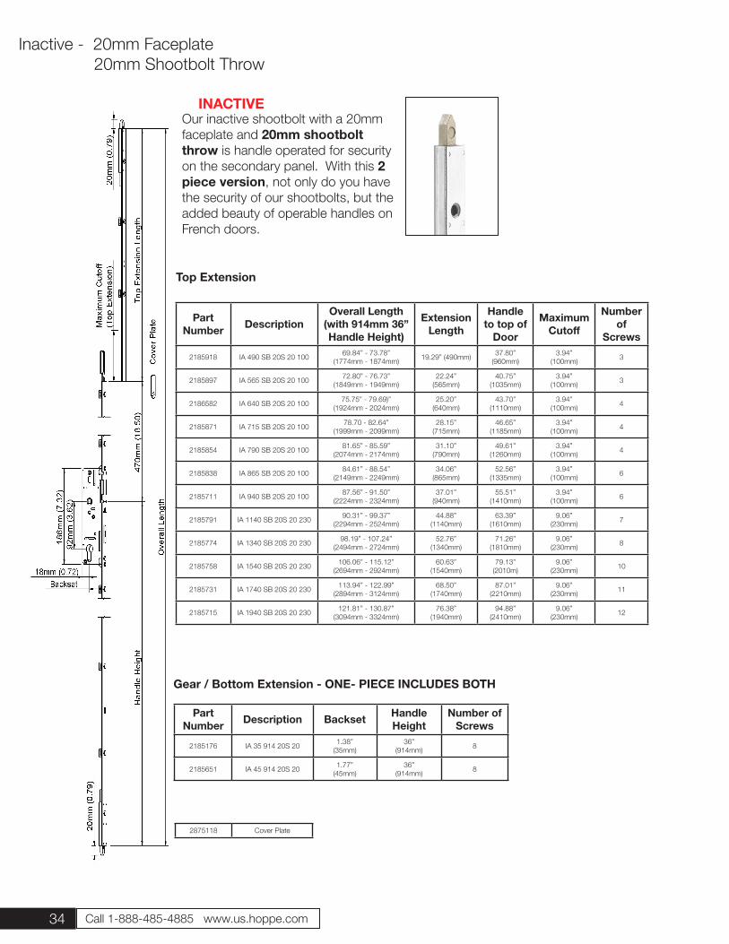
Our inactive shootbolt with a 20mm faceplate and 20mm shootbolt throw is handle operated for security on the secondary panel. With this 2 piece version, not only do you have the security of our shootbolts, but the added beauty of operable handles on French doors.
Part Number Description
Overall Length (with 914mm 36” Handle Height)
Extension Length
Handle to top of
Door
Maximum Cutoff
Number of
Screws
2185918 IA 490 SB 20S 20 100 69.84” - 73.78”(1774mm - 1874mm) 19.29” (490mm) 37.80”
(960mm)3.94”
(100mm) 3
2185897 IA 565 SB 20S 20 100 72.80” - 76.73” (1849mm - 1949mm)
22.24”(565mm)
40.75”(1035mm)
3.94” (100mm) 3
2186582 IA 640 SB 20S 20 100 75.75” - 79.69)”(1924mm - 2024mm)
25.20”(640mm)
43.70”(1110mm)
3.94” (100mm) 4
2185871 IA 715 SB 20S 20 100 78.70 - 82.64”(1999mm - 2099mm)
28.15”(715mm)
46.65”(1185mm)
3.94” (100mm) 4
2185854 IA 790 SB 20S 20 100 81.65” - 85.59”(2074mm - 2174mm)
31.10”(790mm)
49.61”(1260mm)
3.94” (100mm) 4
2185838 IA 865 SB 20S 20 100 84.61” - 88.54” (2149mm - 2249mm)
34.06”(865mm)
52.56”(1335mm)
3.94” (100mm) 6
2185711 IA 940 SB 20S 20 100 87.56” - 91.50”(2224mm - 2324mm)
37.01”(940mm)
55.51”(1410mm)
3.94” (100mm) 6
2185791 IA 1140 SB 20S 20 230 90.31” - 99.37”(2294mm - 2524mm)
44.88”(1140mm)
63.39”(1610mm)
9.06”(230mm) 7
2185774 IA 1340 SB 20S 20 230 98.19” - 107.24”(2494mm - 2724mm)
52.76”(1340mm)
71.26”(1810mm)
9.06”(230mm) 8
2185758 IA 1540 SB 20S 20 230 106.06” - 115.12” (2694mm - 2924mm)
60.63”(1540mm)
79.13”(2010m)
9.06”(230mm) 10
2185731 IA 1740 SB 20S 20 230 113.94” - 122.99” (2894mm - 3124mm)
68.50”(1740mm)
87.01”(2210mm)
9.06”(230mm) 11
2185715 IA 1940 SB 20S 20 230 121.81” - 130.87”(3094mm - 3324mm)
76.38”(1940mm)
94.88”(2410mm)
9.06”(230mm) 12
Top Extension
2875118 Cover Plate
Inactive - 20mm Faceplate 20mm Shootbolt Throw
Part Number Description Backset Handle
HeightNumber of
Screws
2185176 IA 35 914 20S 20 1.38”(35mm)
36”(914mm) 8
2185651 IA 45 914 20S 20 1.77”(45mm)
36”(914mm) 8
Gear / Bottom Extension - ONE- PIECE INCLUDES BOTH
INACTIVE
35
Inactive - 20mm Faceplate 20mm Shootbolt Throw
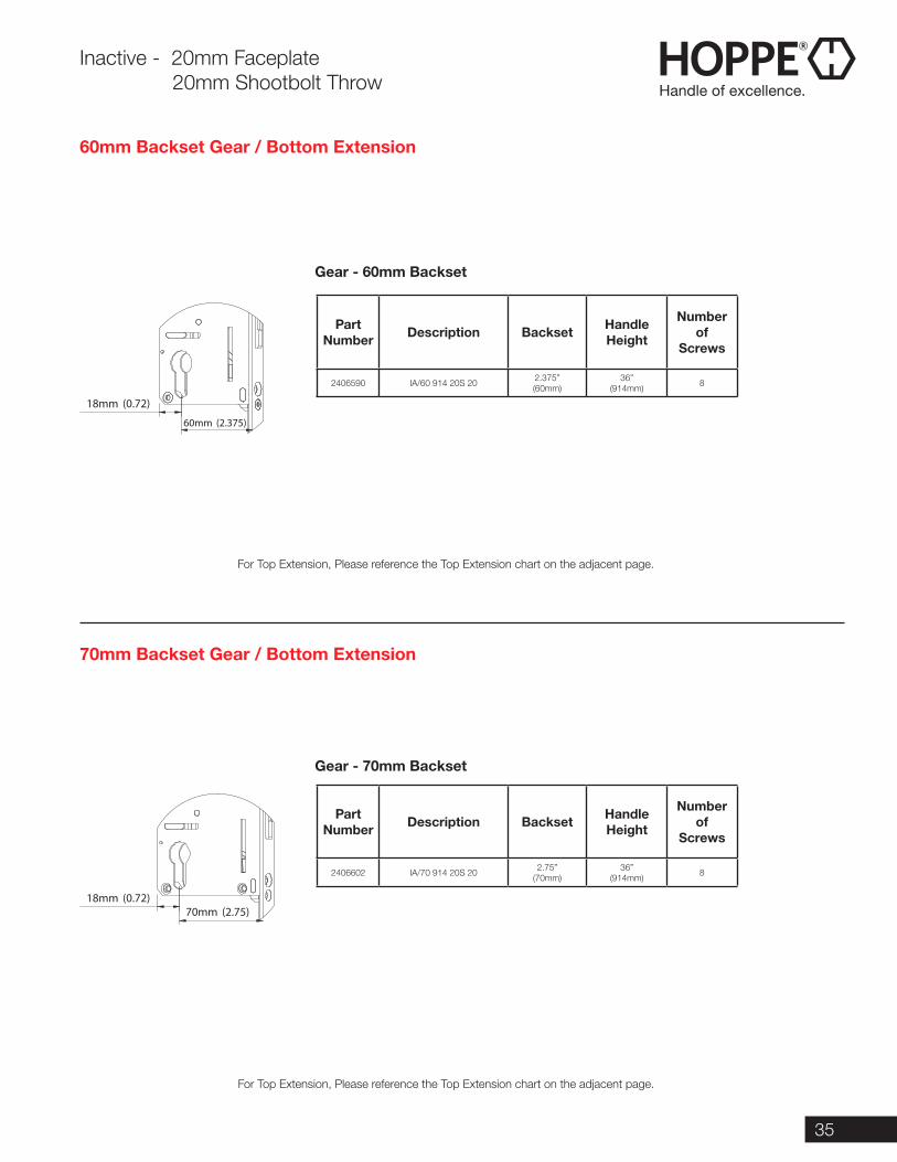
60mm Backset Gear / Bottom Extension
For Top Extension, Please reference the Top Extension chart on the adjacent page.
For Top Extension, Please reference the Top Extension chart on the adjacent page.
70mm Backset Gear / Bottom Extension
60mm (2.375)
18mm (0.72)
70mm (2.75)18mm (0.72)
Part Number Description Backset Handle
Height
Number of
Screws
2406590 IA/60 914 20S 20 2.375”(60mm)
36”(914mm) 8
Part Number Description Backset Handle
Height
Number of
Screws
2406602 IA/70 914 20S 20 2.75”(70mm)
36”(914mm) 8
Gear - 60mm Backset
Gear - 70mm Backset
36 Call 1-888-485-4885 www.us.hoppe.com
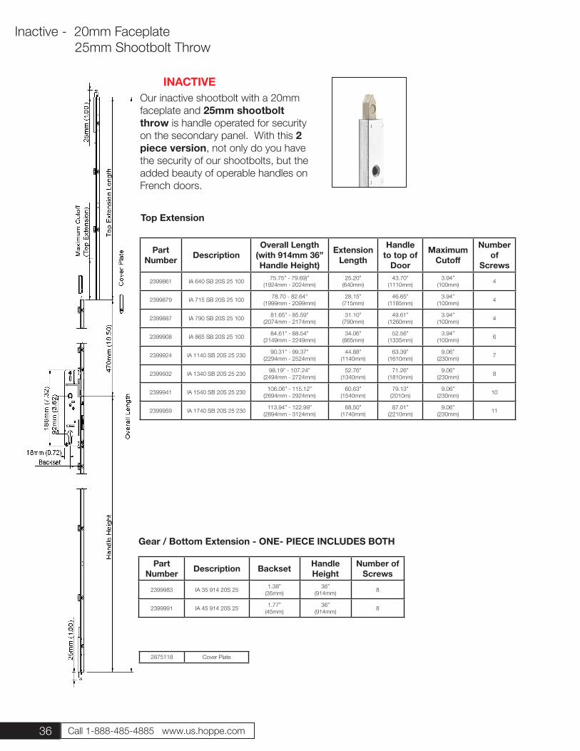
Our inactive shootbolt with a 20mm faceplate and 25mm shootbolt throw is handle operated for security on the secondary panel. With this 2 piece version, not only do you have the security of our shootbolts, but the added beauty of operable handles on French doors.
Part Number Description
Overall Length (with 914mm 36” Handle Height)
Extension Length
Handle to top of
Door
Maximum Cutoff
Number of
Screws
2399861 IA 640 SB 20S 25 100 75.75” - 79.69)”(1924mm - 2024mm)
25.20”(640mm)
43.70”(1110mm)
3.94” (100mm) 4
2399879 IA 715 SB 20S 25 100 78.70 - 82.64”(1999mm - 2099mm)
28.15”(715mm)
46.65”(1185mm)
3.94” (100mm) 4
2399887 IA 790 SB 20S 25 100 81.65” - 85.59”(2074mm - 2174mm)
31.10”(790mm)
49.61”(1260mm)
3.94” (100mm) 4
2399908 IA 865 SB 20S 25 100 84.61” - 88.54” (2149mm - 2249mm)
34.06”(865mm)
52.56”(1335mm)
3.94” (100mm) 6
2399924 IA 1140 SB 20S 25 230 90.31” - 99.37”(2294mm - 2524mm)
44.88”(1140mm)
63.39”(1610mm)
9.06”(230mm) 7
2399932 IA 1340 SB 20S 25 230 98.19” - 107.24”(2494mm - 2724mm)
52.76”(1340mm)
71.26”(1810mm)
9.06”(230mm) 8
2399941 IA 1540 SB 20S 25 230 106.06” - 115.12” (2694mm - 2924mm)
60.63”(1540mm)
79.13”(2010m)
9.06”(230mm) 10
2399959 IA 1740 SB 20S 25 230 113.94” - 122.99” (2894mm - 3124mm)
68.50”(1740mm)
87.01”(2210mm)
9.06”(230mm) 11
Top Extension
2875118 Cover Plate
Inactive - 20mm Faceplate 25mm Shootbolt Throw
Part Number Description Backset Handle
HeightNumber of
Screws
2399983 IA 35 914 20S 25 1.38”(35mm)
36”(914mm) 8
2399991 IA 45 914 20S 25 1.77”(45mm)
36”(914mm) 8
Gear / Bottom Extension - ONE- PIECE INCLUDES BOTH
INACTIVE
37
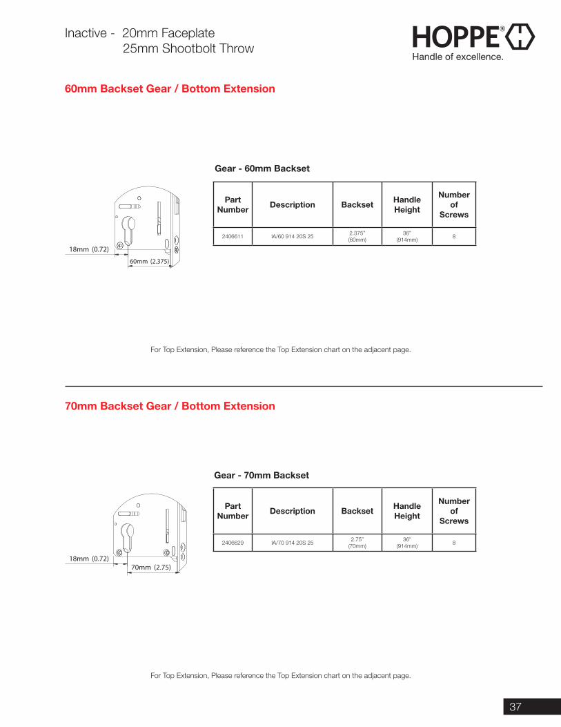
Inactive - 20mm Faceplate 25mm Shootbolt Throw
60mm Backset Gear / Bottom Extension
For Top Extension, Please reference the Top Extension chart on the adjacent page.
For Top Extension, Please reference the Top Extension chart on the adjacent page.
70mm Backset Gear / Bottom Extension
60mm (2.375)
18mm (0.72)
70mm (2.75)18mm (0.72)
Part Number Description Backset Handle
Height
Number of
Screws
2406611 IA/60 914 20S 25 2.375”(60mm)
36”(914mm) 8
Part Number Description Backset Handle
Height
Number of
Screws
2406629 IA/70 914 20S 25 2.75”(70mm)
36”(914mm) 8
Gear - 60mm Backset
Gear - 70mm Backset
38 Call 1-888-485-4885 www.us.hoppe.com
Inactive Flushbolt
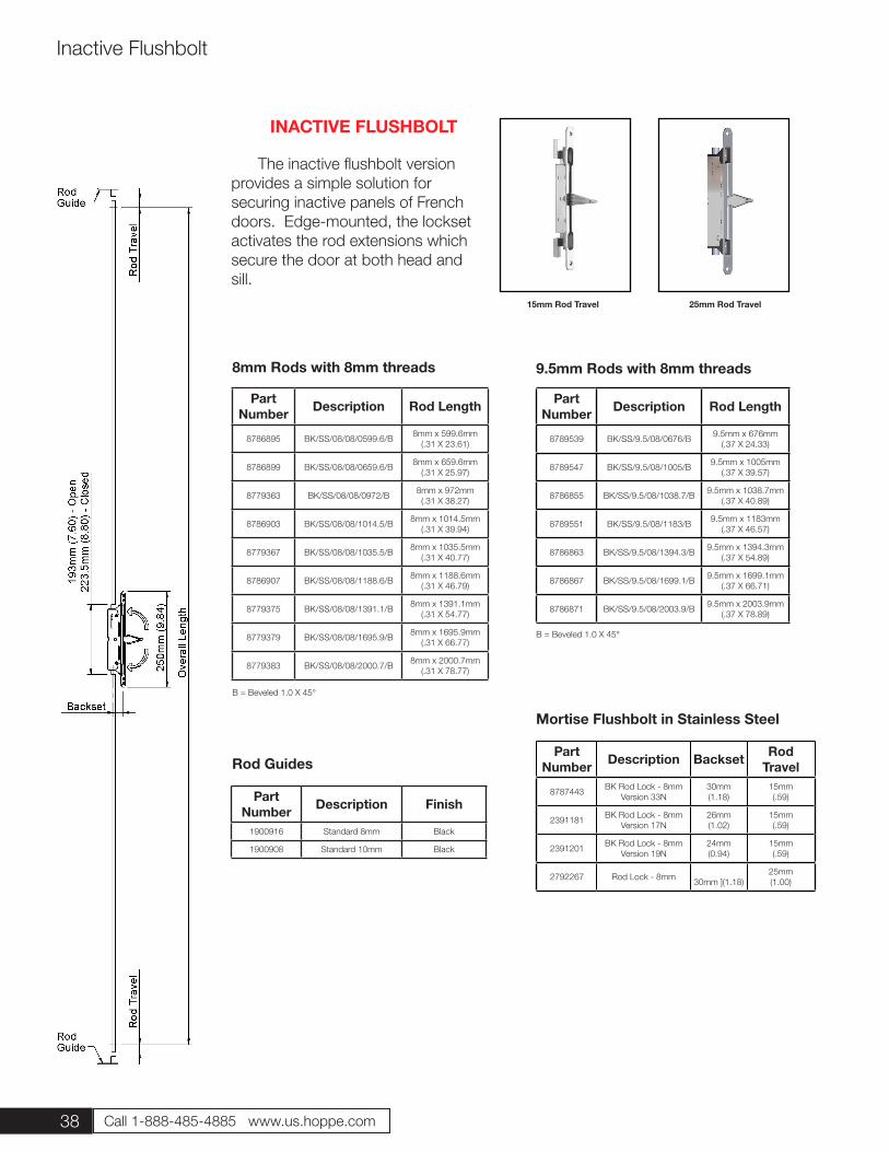
INACTIVE FLUSHBOLT
The inactive flushbolt version provides a simple solution for securing inactive panels of French doors. Edge-mounted, the lockset activates the rod extensions which secure the door at both head and sill.
15mm Rod Travel 25mm Rod Travel
Part Number Description Rod Length
8786895 BK/SS/08/08/0599.6/B 8mm x 599.6mm (.31 X 23.61)
8786899 BK/SS/08/08/0659.6/B 8mm x 659.6mm (.31 X 25.97)
8779363 BK/SS/08/08/0972/B 8mm x 972mm (.31 X 38.27)
8786903 BK/SS/08/08/1014.5/B 8mm x 1014.5mm (.31 X 39.94)
8779367 BK/SS/08/08/1035.5/B 8mm x 1035.5mm (.31 X 40.77)
8786907 BK/SS/08/08/1188.6/B 8mm x 1188.6mm (.31 X 46.79)
8779375 BK/SS/08/08/1391.1/B 8mm x 1391.1mm (.31 X 54.77)
8779379 BK/SS/08/08/1695.9/B 8mm x 1695.9mm (.31 X 66.77)
8779383 BK/SS/08/08/2000.7/B 8mm x 2000.7mm(.31 X 78.77)
Part Number Description Rod Length
8789539 BK/SS/9.5/08/0676/B 9.5mm x 676mm (.37 X 24.33)
8789547 BK/SS/9.5/08/1005/B 9.5mm x 1005mm (.37 X 39.57)
8786855 BK/SS/9.5/08/1038.7/B 9.5mm x 1038.7mm (.37 X 40.89)
8789551 BK/SS/9.5/08/1183/B 9.5mm x 1183mm (.37 X 46.57)
8786863 BK/SS/9.5/08/1394.3/B 9.5mm x 1394.3mm (.37 X 54.89)
8786867 BK/SS/9.5/08/1699.1/B 9.5mm x 1699.1mm (.37 X 66.71)
8786871 BK/SS/9.5/08/2003.9/B 9.5mm x 2003.9mm (.37 X 78.89)
Part Number Description Backset Rod
Travel
8787443 BK Rod Lock - 8mm Version 33N
30mm (1.18)
15mm(.59)
2391181 BK Rod Lock - 8mm Version 17N
26mm (1.02)
15mm(.59)
2391201 BK Rod Lock - 8mm Version 19N
24mm (0.94)
15mm(.59)
2792267 Rod Lock - 8mm 30mm ](1.18)25mm(1.00)
Part Number Description Finish
1900916 Standard 8mm Black
1900908 Standard 10mm Black
Rod Guides
8mm Rods with 8mm threads 9.5mm Rods with 8mm threads
Mortise Flushbolt in Stainless Steel
B = Beveled 1.0 X 45°
B = Beveled 1.0 X 45°
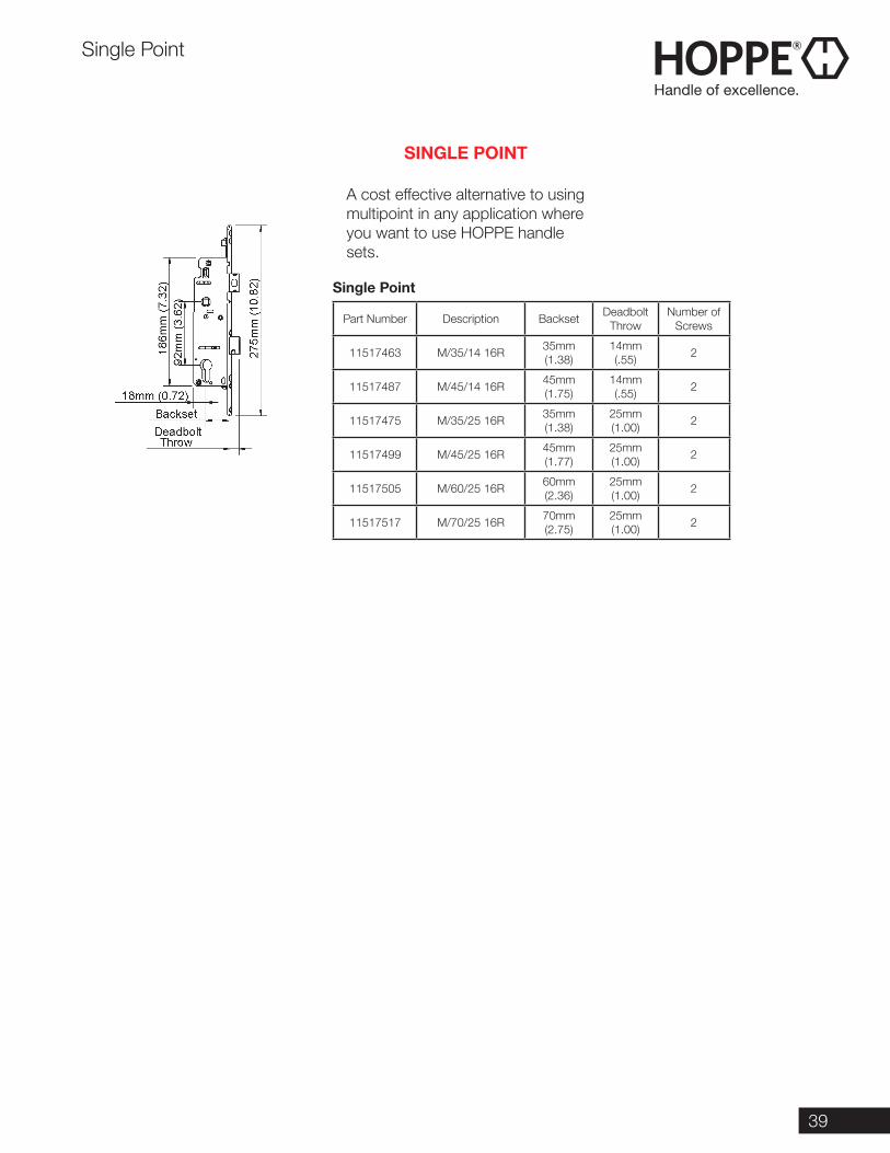
39
A cost effective alternative to using multipoint in any application where you want to use HOPPE handle sets.
Part Number Description Backset Deadbolt Throw
Number of Screws
11517463 M/35/14 16R 35mm (1.38)
14mm (.55) 2
11517487 M/45/14 16R 45mm (1.75)
14mm (.55) 2
11517475 M/35/25 16R 35mm (1.38)
25mm (1.00) 2
11517499 M/45/25 16R 45mm (1.77)
25mm (1.00) 2
11517505 M/60/25 16R 60mm (2.36)
25mm (1.00) 2
11517517 M/70/25 16R 70mm (2.75)
25mm (1.00) 2
Single Point
Single Point
SINGLE POINT
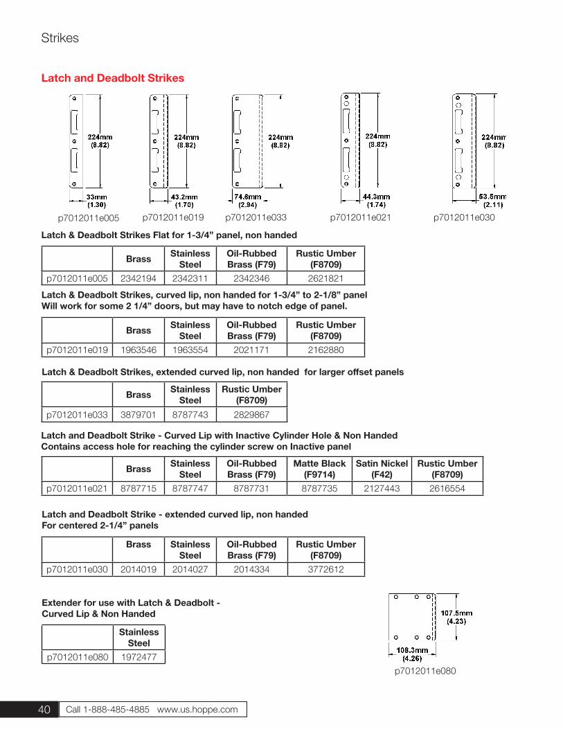
40 Call 1-888-485-4885 www.us.hoppe.com
Strikes
Brass Stainless Steel
Oil-Rubbed Brass (F79)
Rustic Umber (F8709)
p7012011e005 2342194 2342311 2342346 2621821
Latch & Deadbolt Strikes Flat for 1-3/4” panel, non handed
Latch & Deadbolt Strikes, curved lip, non handed for 1-3/4” to 2-1/8” panel Will work for some 2 1/4” doors, but may have to notch edge of panel.
Brass Stainless Steel
Rustic Umber (F8709)
p7012011e033 3879701 8787743 2829867
Latch & Deadbolt Strikes, extended curved lip, non handed for larger offset panels
Brass Stainless Steel
Oil-Rubbed Brass (F79)
Rustic Umber (F8709)
p7012011e019 1963546 1963554 2021171 2162880
Latch and Deadbolt Strike - Curved Lip with Inactive Cylinder Hole & Non HandedContains access hole for reaching the cylinder screw on Inactive panel
Brass Stainless Steel
Oil-Rubbed Brass (F79)
Matte Black (F9714)
Satin Nickel (F42)
Rustic Umber (F8709)
p7012011e021 8787715 8787747 8787731 8787735 2127443 2616554
Latch and Deadbolt Strikes
p7012011e005 p7012011e033p7012011e019 p7012011e021 p7012011e030
Brass Stainless Steel
Oil-Rubbed Brass (F79)
Rustic Umber (F8709)
p7012011e030 2014019 2014027 2014334 3772612
Latch and Deadbolt Strike - extended curved lip, non handedFor centered 2-1/4” panels
Extender for use with Latch & Deadbolt - Curved Lip & Non Handed
Stainless Steel
p7012011e080 1972477p7012011e080
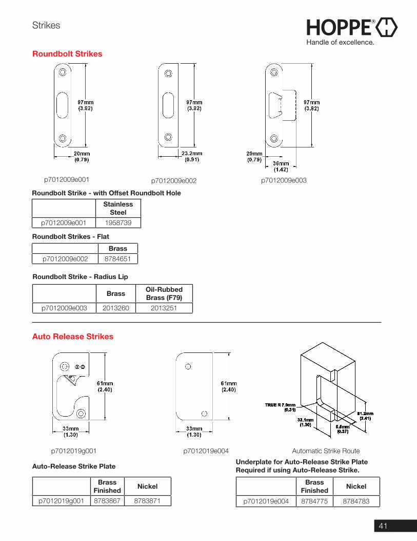
41
Strikes
Roundbolt Strikes
Roundbolt Strikes - Flat
Brassp7012009e002 8784651
Roundbolt Strike - with Offset Roundbolt Hole
Stainless Steel
p7012009e001 1958739
Roundbolt Strike - Radius Lip
Brass Oil-Rubbed Brass (F79)
p7012009e003 2013260 2013251
Auto Release Strikes
Brass Finished Nickel
p7012019g001 8783867 8783871
Brass Finished Nickel
p7012019e004 8784775 8784783
Underplate for Auto-Release Strike PlateRequired if using Auto-Release Strike.Auto-Release Strike Plate
p7012009e002p7012009e001 p7012009e003
p7012019g001 p7012019e004 Automatic Strike Route
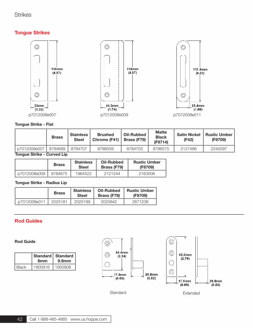
42 Call 1-888-485-4885 www.us.hoppe.com
Tongue Strike - Curved Lip
Tongue Strike - Radius Lip
Tongue Strike - Flat
Brass Stainless Steel
Oil-Rubbed Brass (F79)
Rustic Umber (F8709)
p7012008e009 8784675 1964522 2121244 2163006
Brass Stainless Steel
Oil-Rubbed Brass (F79)
Rustic Umber (F8709)
p7012008e011 2025181 2025199 2025842 2671238
Brass Stainless Steel
Brushed Chrome (F41)
Oil-Rubbed Brass (F79)
Matte Black
(F9714)
Satin Nickel (F42)
Rustic Umber (F8709)
p7012008e007 8784699 8784707 8786559 8784703 8786575 2127486 2245597
Tongue Strikes
Standard 8mm
Standard 9.9mm
Black 1900916 1900908
Rod Guide
p7012008e009 p7012008e011p7012008e007
Rod Guides
Standard Extended
Strikes
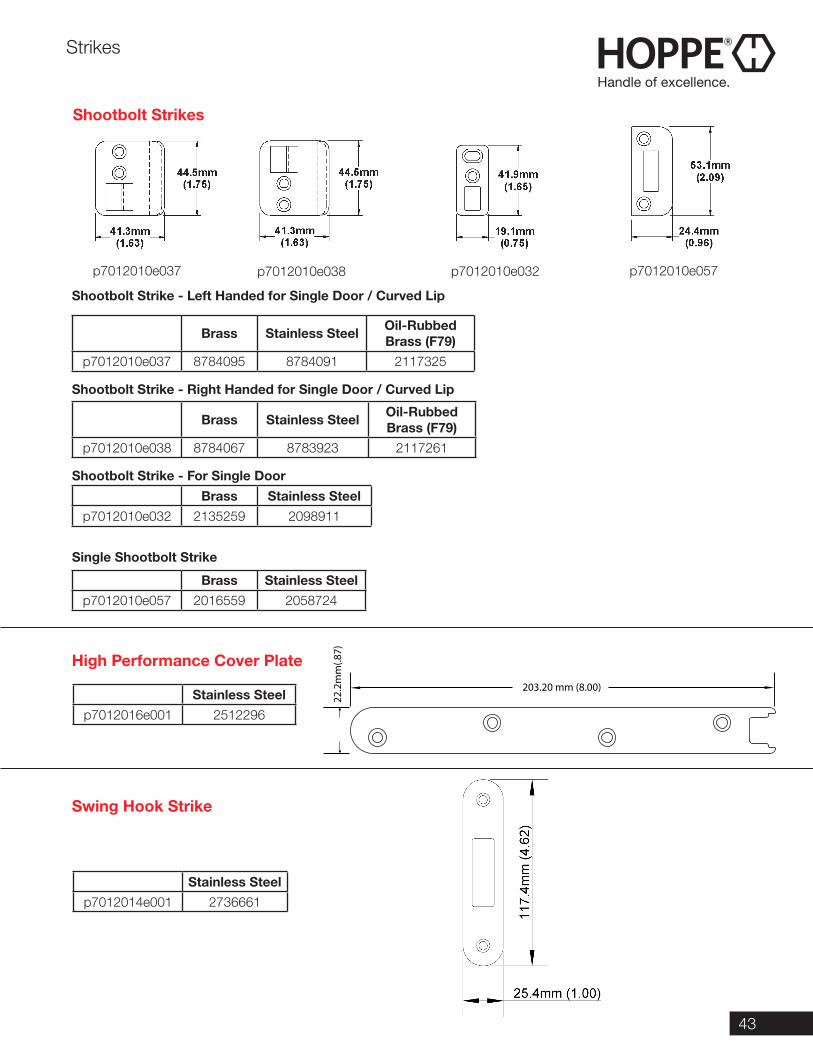
43
Shootbolt Strikes
High Performance Cover Plate
Swing Hook Strike
Brass Stainless Steel Oil-Rubbed Brass (F79)
p7012010e037 8784095 8784091 2117325
Brass Stainless Steel Oil-Rubbed Brass (F79)
p7012010e038 8784067 8783923 2117261
Shootbolt Strike - Left Handed for Single Door / Curved Lip
Shootbolt Strike - Right Handed for Single Door / Curved Lip
Shootbolt Strike - For Single Door
Brass Stainless Steelp7012010e032 2135259 2098911
Brass Stainless Steelp7012010e057 2016559 2058724
Stainless Steelp7012016e001 2512296
Stainless Steelp7012014e001 2736661
Single Shootbolt Strike
p7012010e037 p7012010e038 p7012010e032 p7012010e057
Strikes
203.20 mm (8.00)
22.2
mm
(.87)
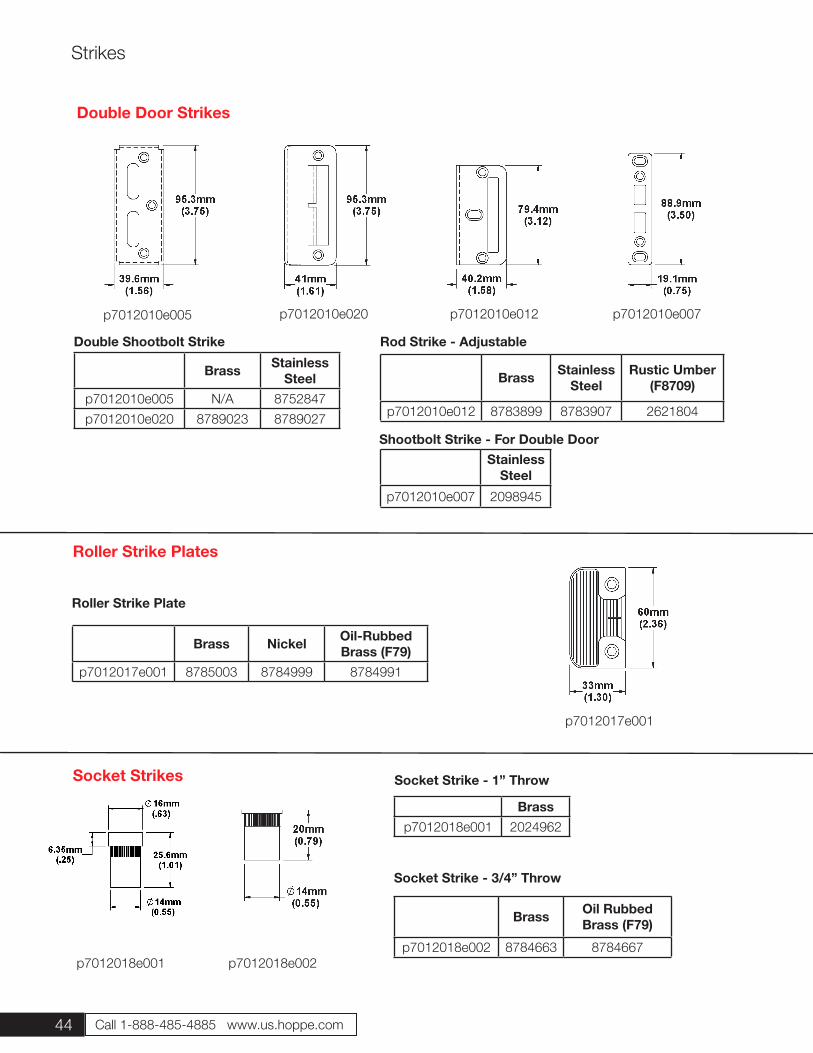
44 Call 1-888-485-4885 www.us.hoppe.com
Brass Oil Rubbed Brass (F79)
p7012018e002 8784663 8784667
Socket Strike - 3/4” Throw
Brassp7012018e001 2024962
Socket Strike - 1” Throw
Double Door Strikes
Brass Stainless Steel
p7012010e005 N/A 8752847p7012010e020 8789023 8789027
Brass Stainless Steel
Rustic Umber (F8709)
p7012010e012 8783899 8783907 2621804
Rod Strike - AdjustableDouble Shootbolt Strike
p7012010e005 p7012010e020 p7012010e012 p7012010e007
Stainless Steel
p7012010e007 2098945
Shootbolt Strike - For Double Door
p7012018e002p7012018e001
Socket Strikes
Strikes
Brass Nickel Oil-Rubbed Brass (F79)
p7012017e001 8785003 8784999 8784991
Roller Strike Plate
Roller Strike Plates
p7012017e001
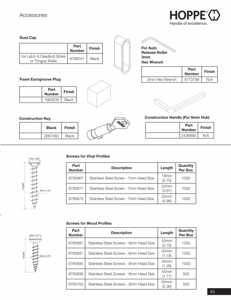
45
Part Number Finish
for Latch & Deadbolt Strike or Tongue Strike 8786547 Black
Dust Cap
Foam Eurogroove Plug
Part Number Finish
1963538 Black
Construction Key
Black Finish
2667482 Black
Part Number Finish
3mm Hex Wrench 8773799 N/A
Part Number Finish
2426890 N/A
Hex Wrench
Construction Handle (For 8mm Hub)
Part Number Description Length Quantity
Per Box
8785667 Stainless Steel Screw - 7mm Head Size 19mm (0.75) 1000
8785671 Stainless Steel Screw - 7mm Head Size 22mm (0.87) 1000
8785675 Stainless Steel Screw - 7mm Head Size 25mm (0.98) 1000
Screws for Vinyl Profiles
Screws for Wood Profiles
Part Number Description Length Quantity
Per Box
8785687 Stainless Steel Screws - 8mm Head Size 20mm (0.79) 1000
8785691 Stainless Steel Screws - 8mm Head Size 30mm (1.18) 1000
8785695 Stainless Steel Screws - 8mm Head Size 35mm (1.38) 1000
8785699 Stainless Steel Screws - 8mm Head Size 45mm (1.77) 500
8785703 Stainless Steel Screws - 8mm Head Size 60mm (2.36) 500
7mm (.28”)
4mm (.15”)
Leng
thLe
ngth
4mm (.15”)
8mm (.31”)
Accessories
For Auto Release Roller3mm
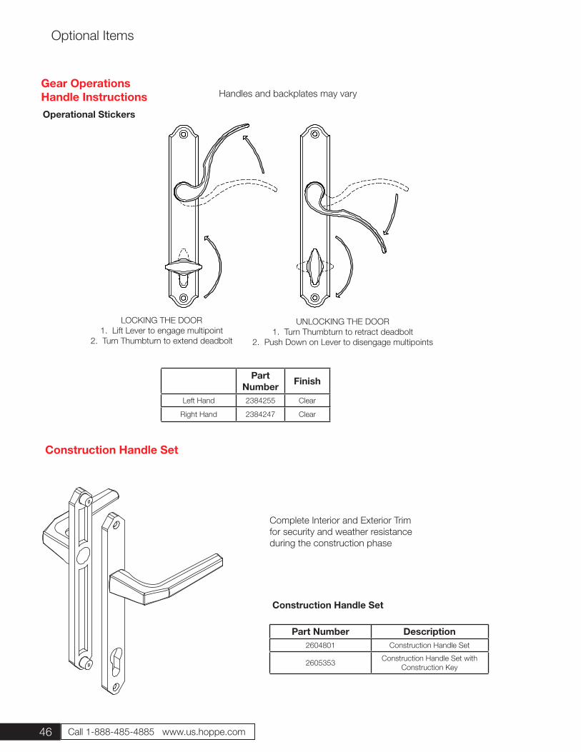
46 Call 1-888-485-4885 www.us.hoppe.com
Optional Items
Complete Interior and Exterior Trim for security and weather resistance during the construction phase
Construction Handle Set
Part Number Description2604801 Construction Handle Set
2605353 Construction Handle Set with Construction Key
Construction Handle Set
Part Number Finish
Left Hand 2384255 Clear
Right Hand 2384247 Clear
Gear OperationsHandle Instructions
LOCKING THE DOOR1. Lift Lever to engage multipoint
2. Turn Thumbturn to extend deadbolt
UNLOCKING THE DOOR1. Turn Thumbturn to retract deadbolt
2. Push Down on Lever to disengage multipoints
Handles and backplates may vary
Operational Stickers
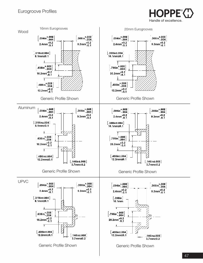
47
Eurogroove Profiles
Wood
Aluminum
UPVC
Generic Profile ShownGeneric Profile Shown
Generic Profile ShownGeneric Profile Shown
Generic Profile ShownGeneric Profile Shown
16mm Eurogrooves 20mm Eurogrooves
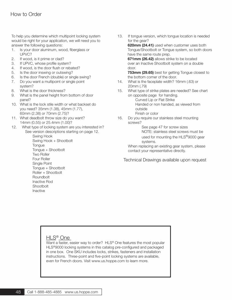
48 Call 1-888-485-4885 www.us.hoppe.com
To help you determine which multipoint locking system would be right for your application, we will need you to answer the following questions:1. Is your door aluminum, wood, fiberglass or UPVC?2. If wood, is it prime or clad?3. If UPVC, whose profile system?4. If wood, is the door flush or rebated?5. Is the door inswing or outswing?6. Is the door French (double) or single swing?7. Do you want a multipoint or single point system?8. What is the door thickness?9. What is the panel height from bottom of door panel?10. What is the lock stile width or what backset do you need? 35mm (1.38), 45mm (1.77), 60mm (2.38) or 70mm (2.75)?11. What deadbolt throw size do you want? 14mm (0.55) or 25.4mm (1.00)?12. What type of locking system are you interested in? See version descriptions starting on page 12. Swing Hook Swing Hook + Shootbolt Tongue Tongue + Shootbolt Two Roller Four Roller Single Point Tongue + Shootbolt Roller + Shootbolt Roundbolt Inactive Rod Shootbolt Inactive
13. If tongue version, which tongue location is needed for the gear?
620mm (24.41) used when customer uses both Tongue/Shootbolt or Tongue system, so both doors have the same route prep. 671mm (26.42) allows strike to be located over an Inactive Shootbolt system on a double door. 753mm (29.65) best for getting Tongue closest to the bottom corner of the door.
14. What is the faceplate width? 16mm (.63) or 20mm (.79)15. What type of strike plates are needed? See chart on opposite page for handing. Curved Lip or Flat Strike Handed or non handed, as viewed from outside Finish or color16. Do you require our stainless steel mounting screws? See page 47 for screw sizes NOTE: stainless steel screws must be used for mounting the HLS®9000 gear systems. When replacing an existing gear system, please contact your representative directly.
How to Order
Technical Drawings available upon request
HLS® One Want a faster, easier way to order? HLS® One features the most popular HLS®9000 locking systems in this catalog pre-configured and packaged in one box. One SKU includes locks, strikes, fasteners and installation instructions. Three-point and five-point locking systems are available, even for French doors. Visit www.us.hoppe.com to learn more.
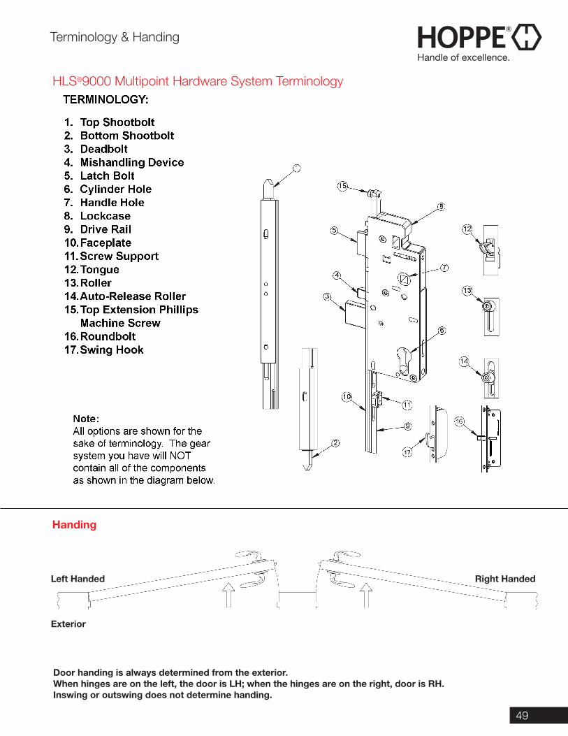
49
Left Handed
Exterior
Right Handed
Door handing is always determined from the exterior.When hinges are on the left, the door is LH; when the hinges are on the right, door is RH.Inswing or outswing does not determine handing.
Terminology & Handing
HLS®9000 Multipoint Hardware System Terminology
Handing
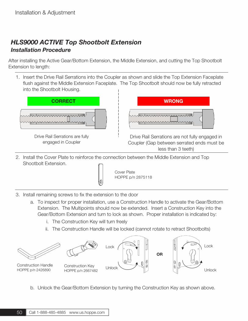
50 Call 1-888-485-4885 www.us.hoppe.com
Installation & Adjustment
After installing the Active Gear/Bottom Extension, the Middle Extension, and cutting the Top Shootbolt Extension to length:
1. Insert the Drive Rail Serrations into the Coupler as shown and slide the Top Extension Faceplate flush against the Middle Extension Faceplate. The Top Shootbolt should now be fully retracted into the Shootbolt Housing.
2. Install the Cover Plate to reinforce the connection between the Middle Extension and Top Shootbolt Extension.
3. Install remaining screws to fix the extension to the door a. To inspect for proper installation, use a Construction Handle to activate the Gear/Bottom
Extension. The Multipoints should now be extended. Insert a Construction Key into the Gear/Bottom Extension and turn to lock as shown. Proper installation is indicated by:
i. The Construction Key will turn freely ii. The Construction Handle will be locked (cannot rotate to retract Shootbolts)
b. Unlock the Gear/Bottom Extension by turning the Construction Key as shown above.
c. Use the Construction Handle to retract the Multipoints
Construction Handle HOPPE p/n 2426890
Construction Key HOPPE p/n 2667482
CORRECT WRONG
Drive Rail Serrations are fully engaged in Coupler
Drive Rail Serrations are not fully engaged in Coupler (Gap between serrated ends must be
less than 3 teeth)
Lock
Unlock
Lock
Unlock
OR
HLS9000 ACTIVE Top Shootbolt Extension Installation Procedure
Cover Plate HOPPE p/n 2875118
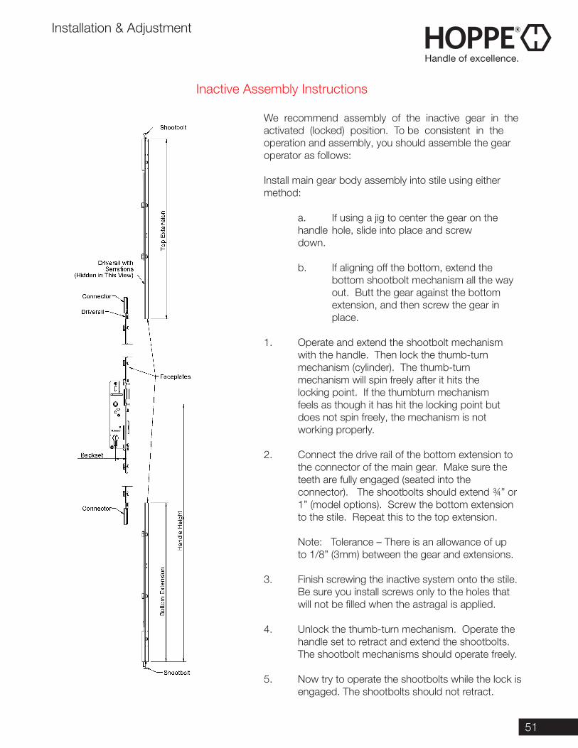
51
Inactive Assembly Instructions
Installation & Adjustment
We recommend assembly of the inactive gear in the activated (locked) position. To be consistent in the operation and assembly, you should assemble the gear operator as follows: Install main gear body assembly into stile using either method:
a. If using a jig to center the gear on the handle hole, slide into place and screw down. b. If aligning off the bottom, extend the bottom shootbolt mechanism all the way out. Butt the gear against the bottom extension, and then screw the gear in place.
1. Operate and extend the shootbolt mechanism with the handle. Then lock the thumb-turn mechanism (cylinder). The thumb-turn mechanism will spin freely after it hits the locking point. If the thumbturn mechanism feels as though it has hit the locking point but does not spin freely, the mechanism is not working properly.
2. Connect the drive rail of the bottom extension to the connector of the main gear. Make sure the teeth are fully engaged (seated into the connector). The shootbolts should extend ¾” or 1” (model options). Screw the bottom extension to the stile. Repeat this to the top extension.
Note: Tolerance – There is an allowance of up to 1/8” (3mm) between the gear and extensions.
3. Finish screwing the inactive system onto the stile. Be sure you install screws only to the holes that will not be filled when the astragal is applied.
4. Unlock the thumb-turn mechanism. Operate the handle set to retract and extend the shootbolts. The shootbolt mechanisms should operate freely.
5. Now try to operate the shootbolts while the lock is engaged. The shootbolts should not retract.
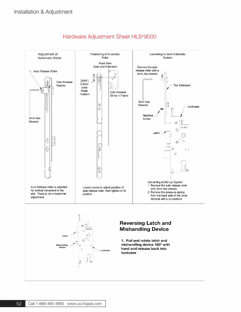
52 Call 1-888-485-4885 www.us.hoppe.com
Installation & Adjustment
Hardware Adjustment Sheet HLS®9000
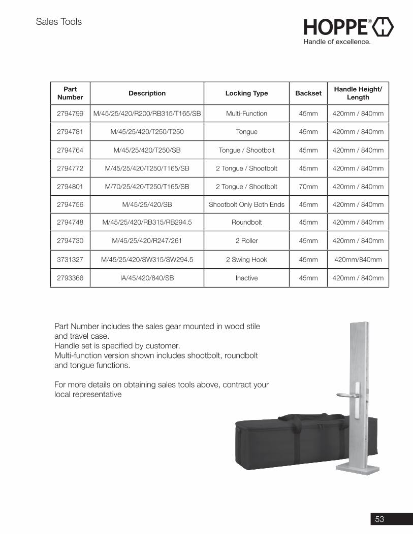
53
Part Number Description Locking Type Backset Handle Height/
Length
2794799 M/45/25/420/R200/RB315/T165/SB Multi-Function 45mm 420mm / 840mm
2794781 M/45/25/420/T250/T250 Tongue 45mm 420mm / 840mm
2794764 M/45/25/420/T250/SB Tongue / Shootbolt 45mm 420mm / 840mm
2794772 M/45/25/420/T250/T165/SB 2 Tongue / Shootbolt 45mm 420mm / 840mm
2794801 M/70/25/420/T250/T165/SB 2 Tongue / Shootbolt 70mm 420mm / 840mm
2794756 M/45/25/420/SB Shootbolt Only Both Ends 45mm 420mm / 840mm
2794748 M/45/25/420/RB315/RB294.5 Roundbolt 45mm 420mm / 840mm
2794730 M/45/25/420/R247/261 2 Roller 45mm 420mm / 840mm
3731327 M/45/25/420/SW315/SW294.5 2 Swing Hook 45mm 420mm/840mm
2793366 IA/45/420/840/SB Inactive 45mm 420mm / 840mm
Part Number includes the sales gear mounted in wood stile and travel case.Handle set is specified by customer.Multi-function version shown includes shootbolt, roundbolt and tongue functions.
For more details on obtaining sales tools above, contract your local representative
Sales Tools
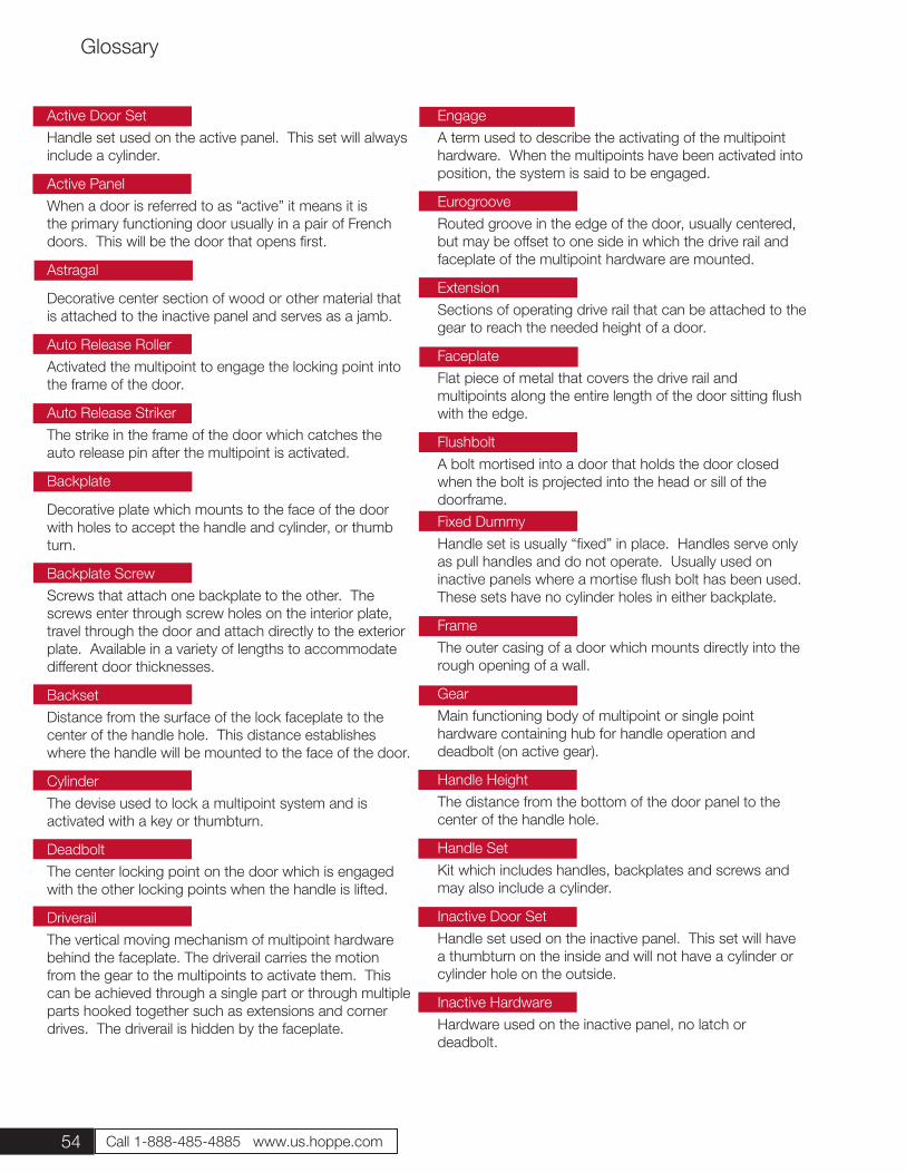
54 Call 1-888-485-4885 www.us.hoppe.com
Glossary
EngageA term used to describe the activating of the multipoint hardware. When the multipoints have been activated into position, the system is said to be engaged.
EurogrooveRouted groove in the edge of the door, usually centered, but may be offset to one side in which the drive rail and faceplate of the multipoint hardware are mounted.
ExtensionSections of operating drive rail that can be attached to the gear to reach the needed height of a door.
FaceplateFlat piece of metal that covers the drive rail and multipoints along the entire length of the door sitting flush with the edge.
FlushboltA bolt mortised into a door that holds the door closed when the bolt is projected into the head or sill of the doorframe.Fixed DummyHandle set is usually “fixed” in place. Handles serve only as pull handles and do not operate. Usually used on inactive panels where a mortise flush bolt has been used. These sets have no cylinder holes in either backplate.
FrameThe outer casing of a door which mounts directly into the rough opening of a wall.
GearMain functioning body of multipoint or single point hardware containing hub for handle operation and deadbolt (on active gear).
Handle HeightThe distance from the bottom of the door panel to the center of the handle hole.
Handle SetKit which includes handles, backplates and screws and may also include a cylinder.
Inactive Door SetHandle set used on the inactive panel. This set will have a thumbturn on the inside and will not have a cylinder or cylinder hole on the outside.
Inactive HardwareHardware used on the inactive panel, no latch or deadbolt.
Active Door SetHandle set used on the active panel. This set will always include a cylinder.
Active PanelWhen a door is referred to as “active” it means it is the primary functioning door usually in a pair of French doors. This will be the door that opens first.
Astragal
Decorative center section of wood or other material that is attached to the inactive panel and serves as a jamb.
Auto Release RollerActivated the multipoint to engage the locking point into the frame of the door.
Auto Release StrikerThe strike in the frame of the door which catches the auto release pin after the multipoint is activated.
Backplate
Decorative plate which mounts to the face of the door with holes to accept the handle and cylinder, or thumb turn.
Backplate ScrewScrews that attach one backplate to the other. The screws enter through screw holes on the interior plate, travel through the door and attach directly to the exterior plate. Available in a variety of lengths to accommodate different door thicknesses.
BacksetDistance from the surface of the lock faceplate to the center of the handle hole. This distance establishes where the handle will be mounted to the face of the door.
CylinderThe devise used to lock a multipoint system and is activated with a key or thumbturn.
DeadboltThe center locking point on the door which is engaged with the other locking points when the handle is lifted.
DriverailThe vertical moving mechanism of multipoint hardware behind the faceplate. The driverail carries the motion from the gear to the multipoints to activate them. This can be achieved through a single part or through multiple parts hooked together such as extensions and corner drives. The driverail is hidden by the faceplate.
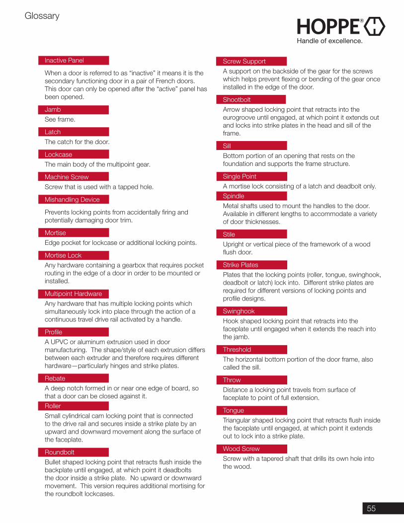
55
Glossary
Inactive Panel
When a door is referred to as “inactive” it means it is the secondary functioning door in a pair of French doors. This door can only be opened after the “active” panel has been opened.
JambSee frame.
LatchThe catch for the door.
LockcaseThe main body of the multipoint gear.
Machine ScrewScrew that is used with a tapped hole.
Mishandling Device
Prevents locking points from accidentally firing and potentially damaging door trim.
MortiseEdge pocket for lockcase or additional locking points.
Mortise LockAny hardware containing a gearbox that requires pocket routing in the edge of a door in order to be mounted or installed.
Multipoint HardwareAny hardware that has multiple locking points which simultaneously lock into place through the action of a continuous travel drive rail activated by a handle.
ProfileA UPVC or aluminum extrusion used in door manufacturing. The shape/style of each extrusion differs between each extruder and therefore requires different hardware—particularly hinges and strike plates.
RebateA deep notch formed in or near one edge of board, so that a door can be closed against it.RollerSmall cylindrical cam locking point that is connected to the drive rail and secures inside a strike plate by an upward and downward movement along the surface of the faceplate.
RoundboltBullet shaped locking point that retracts flush inside the backplate until engaged, at which point it deadbolts the door inside a strike plate. No upward or downward movement. This version requires additional mortising for the roundbolt lockcases.
Screw SupportA support on the backside of the gear for the screws which helps prevent flexing or bending of the gear once installed in the edge of the door.
ShootboltArrow shaped locking point that retracts into the eurogroove until engaged, at which point it extends out and locks into strike plates in the head and sill of the frame.
SillBottom portion of an opening that rests on the foundation and supports the frame structure.
Single PointA mortise lock consisting of a latch and deadbolt only.SpindleMetal shafts used to mount the handles to the door. Available in different lengths to accommodate a variety of door thicknesses.
StileUpright or vertical piece of the framework of a wood flush door.
Strike PlatesPlates that the locking points (roller, tongue, swinghook, deadbolt or latch) lock into. Different strike plates are required for different versions of locking points and profile designs.
SwinghookHook shaped locking point that retracts into the faceplate until engaged when it extends the reach into the jamb.
ThresholdThe horizontal bottom portion of the door frame, also called the sill.
ThrowDistance a locking point travels from surface of faceplate to point of full extension.
TongueTriangular shaped locking point that retracts flush inside the faceplate until engaged, at which point it extends out to lock into a strike plate.
Wood ScrewScrew with a tapered shaft that drills its own hole into the wood.
HOPPE North America, Inc.
205 E. Blackhawk DriveFort Atkinson, WI 53538-1268920-563-2626Fax: 920-563-4408
1-888-485-4885 [email protected]
1/17/100