Embed Size (px)
Citation preview

_______________________________________________________________________________________________________
_____________________________________________________________________________________________________________
HLE60 SERIES
PARKER HANNIFIN CORPORATION 1140 SANDYHILL ROAD , IRWIN PA 15642 PH 724-861-8200
HLE60 SERIES LINEAR DRIVES
INSTALLATION , OPERATION , AND MAINTENANCE MANUAL MANUAL NO. 100-5312-01 REV 5
HLE60 SR -SQUARE RAIL VERSION HLE60 RB� ROLLER WHEEL BEARING VERSION

_______________________________________________________________________________________________________
_____________________________________________________________________________________________________________
HLE60 SERIES
PARKER HANNIFIN CORPORATION 1140 SANDYHILL ROAD , IRWIN PA 15642 PH 724-861-8200 2
REVISION NOTES:
REV 4 1-20-2006 CHANGED REVISION CODE FROM NUMBERS TO LETTERS UPDATED BELT TENSION PHOTO PG 32 PART#�S AND DESCRIPTIONS
REV 5 3-12-2007 COMPLETE UPDATE OF MANUAL TO HLE60 GEN2

_______________________________________________________________________________________________________
_____________________________________________________________________________________________________________
HLE60 SERIES
PARKER HANNIFIN CORPORATION 1140 SANDYHILL ROAD , IRWIN PA 15642 PH 724-861-8200 3
TABLE OF CONTENTS 1 SAFETY...............................................4
1.1GENERAL...................................................... 4 1.2 IDENTIFICATION ......................................... 4 1.3 END USER SAFETY NOTICE ..................... 4 1.4 SAFETY OPERATING ................................. 5 1.5 ADVICE ON PARTICULAR DANGERS ....... 5 1.6 UNAUTORISED MODIFICATION ................ 5 1.7 HANDLING TRANSPORTING ..................... 5
2 TECHNICAL DATA ..............................6 2.1 PRODUCT CONSTRUCTION...................... 6 2.2 TECHNICAL DATA....................................... 7 2.3 CARRIAGE LOADING SR............................ 8 2.4 CARRIAGE LOADING RB............................ 9 2.5 DIMENSIONS............................................. 10
2.5.1 DIMENSIONS HLE60RB ..................... 10 2.5.2 DIMENSIONS HLE60SR ..................... 11
3 INSTALLATION .................................12 3.1 GENERAL................................................... 12 3.2 SUBSTRUCTURE PREPARATION ........... 12 3.3 INSTALLING............................................... 12
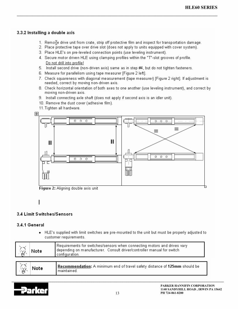
3.3.1 INSTALLING SINGLE AXIS ................ 12 3.3.2 IINSTALLING DUAL AXIS.................... 13
3.4 LIMIT SWITCHES ...................................... 13 3.4.1 GENERAL ............................................ 13 3.4.2 SETTING UP END OF TRAVELS........ 14
4 MAINTENANCE .................................15 4.1 MAINTENANCE SCHEDULE..................... 15 4.2 REPLACEMENT INTERVAL STRIP SEAL/ WEARING PARTS ..................................... 15 4.3 ABNORMAL TIMING BELT WEAR............ 16 4.4 MAINTENANCE & REPAIR........................ 17 4.4.1 SAFETY NOTICE.............................. 17 4.5 REPLACING, TENSIONING, AND ALIGNING TIMINGBELTS �.....................17
4.5.1 GENERAL INFORMATION.................. 17 4.5.2 REPLACING TIMING BELT................. 17 4.5.2 TENSIONING TIMING BELT ............... 17 4.5.2 CHECKING ADJUSTING BELT TENSION���������.����....17 4.5.3 MEASURING TIMING BELT................ 18 4.5.4 TIMING BELT TRACKING................... 18
4.6 CARRIAGE................................................. 19 4.6.1 CHECKING CARRIAGE PLAYRB ....... 19 4.6.2 ADJUSTING CARRIAGE WHEELS..... 19 4.6.3 CHECKING CARRIAGE PLAYSR ....... 20 4.6.4 CHANGING BEARING BLOCK SR...... 20 4.6.5 LUBRICATION SR ............................... 21 4.6.6 REPLACING SQUARE RAIL SR ......... 21
5 HLE60 CONFIGURABLE............... 24-25
6 ASSEMBLIES HLE60RB������. HLE60RB ..........................................................26 HLE60RB-NL- CARRIAGE��������...27 HLE60RB-VL-CARRIAGE���������.28 ARO/ALO-HLE60RB .........................................29 ARW/ALW-HLE60RB����.������...30 MBR./MBL-HLE60RB........................................31 MRW/MLW-HLE60RB��.��������..32 WBO-HLE60RB.................................................33 WRO/WLO-HLE60RB����������...34 TESION STATION HLE60RB�������..35
7 ASSEMBLIES HLE60SR������. HLE60SR ..........................................................36 HLE60SR-NL- CARRIAGE��������...37 HLE60SR-VL-CARRIAGE���������.38 ARO/ALO-HLE60SR .........................................39 ARW/ALW-HLE60SR����.������...40 MBR./MBL-HLE60SR........................................41 MRW/MLW-HLE60SR��.��������..42 WBO-HLE60SR.................................................43 WRO/WLO-HLE60SR����������...44 TESION STATION HLE60SR�������..45
8 GEARBOX INFORMATION������. GEARBOX TECHNICAL INFO .........................46 GEARBOX MOMENT OF INERTIAS�..��...47 GEARBOX DIMENSIONAL��..������48 GEARBOX SHAFT LOADING ..........................48 MOTOR MOUNTING����.����...�...49

_______________________________________________________________________________________________________
_____________________________________________________________________________________________________________
HLE60 SERIES
PARKER HANNIFIN CORPORATION 1140 SANDYHILL ROAD , IRWIN PA 15642 PH 724-861-8200 4
Safety
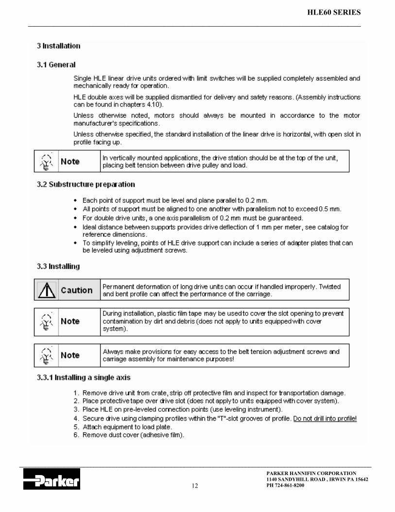
1.1 General
It is the responsibility of the end user to ensure that equipment is installed and operated in accordance with both local and federal safety codes and guidelines.
The user must ensure that the attachment of workpieces/tools or other devices on the moving carriage of the linear unit does not endanger persons and/or property.
1.2 Symbols and Definitions used within this document
Special attention with regard to the safety of personnel, equipment and property should be considered when one or more of the symbols listed below are shown in this document. During equipment installation and operation, any area/condition considered unsafe should be identified by posting appropriate signs or placards.
Safety notices used:
Danger Dangerous situation - can lead to death or serious physical injury if not otherwise prevented by corre-
sponding safety measures.
Warning Possible dangerous situation - can lead to possible serious injury if not otherwise prevented by corre-
sponding safety measures.
Caution Possible dangerous situation - can lead to minor physical injury or da-m-age to property if not other-
wise prevented by corresponding safety measures.
Note Important product information - special handling instructions or indicates a certain section of the
handbook to which you should refer.
1.2.1 Operating personnel
The following work should only be carried out by trained and authorized personnel:
Installation and calibration of the linear drive. Connection of safety limit switches. Installation and start-up of motors and drives.
1.3 End User Safety notices
Supervisors, Technicians, and Installation personnel should familiarize themselves with chapters on "Safety" and �Installation� of this document prior to Installation/operation of equipment.

_______________________________________________________________________________________________________
_____________________________________________________________________________________________________________
HLE60 SERIES
PARKER HANNIFIN CORPORATION 1140 SANDYHILL ROAD , IRWIN PA 15642 PH 724-861-8200 5
1.4 Safety notice for operating personnel
Operating personnel must inspect linear drive unit(s)/machine once per shift for any signs of visible damage or loose hardware. Do not operate equipment suspected of erratic behavior or unusual noise levels.
Parker has specially designed components and accessories. Use only genuine Parker replacement parts. Use of unauthorized parts can effect machine performance and safety.
We accept no liability for damages arising through the use of non-genuine parts and accessories.
We accept no liability for safety features removed or disabled.
Use Federal and local safety requirements/regulations during installing and operation.
1.5 Advice on particular dangers HLE linear drives must be supported at the prescribed minimum distances (see Chapter 3.2).
Stand clear of moving parts
1.6 Unauthorized conversions and modifications
Linear drive units can not be altered in any manner that will affect safety. Any unauthorized alterations will exclude any liability on the part of Parker.
1.7 Handling and Transporting
Danger When lifting, stand clear of suspended load(s)!
Ensure parts subject to movement do not move off-center or shift out of position.
Caution When transporting long axes, permanent deformation of the aluminum profile due to de-
flection can result if not supported properly. Changes in profile straightness can adversely affect the performance of the moving carriage.
Always use transport equipment with adequate lifting capacity. Lifting straps or ropes must not be twisted, knotted, or frayed. If several ropes are used, all should be under equal tension.
An estimate of weight on the HLE 60 Series can be made as follows:
Figure 1: Reference value for HLE 60 Series transportation weight (with motor and gearbox)
Weight
HLE 60 SR HLE 60 RB
Basic Unit (0 Travel) 20.3 kg 17 kg
Each additional Meter 5.5 Kg 3.62 kg
_______________________________________________________________________________________________________
_____________________________________________________________________________________________________________
HLE60 SERIES
PARKER HANNIFIN CORPORATION 1140 SANDYHILL ROAD , IRWIN PA 15642 PH 724-861-8200 6
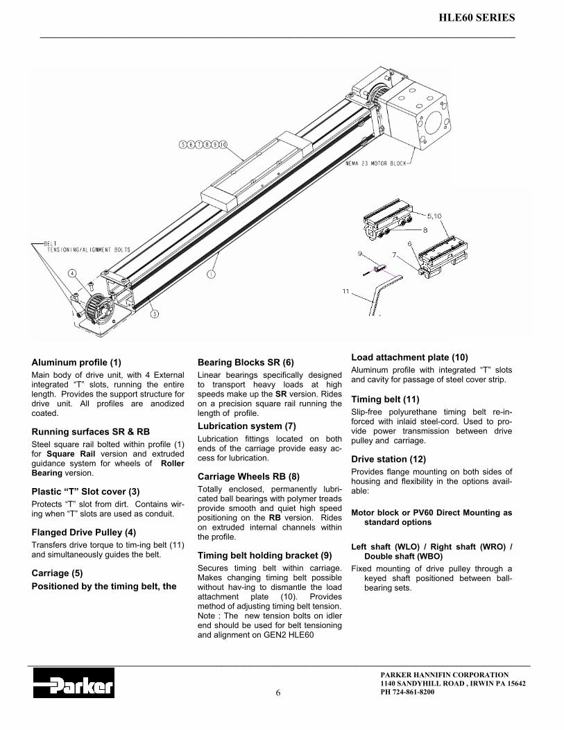
Aluminum profile (1) Main body of drive unit, with 4 External integrated �T� slots, running the entire length. Provides the support structure for drive unit. All profiles are anodized coated.
Running surfaces SR & RB Steel square rail bolted within profile (1) for Square Rail version and extruded guidance system for wheels of Roller Bearing version.
Plastic �T� Slot cover (3) Protects �T� slot from dirt. Contains wir-ing when �T� slots are used as conduit.
Flanged Drive Pulley (4) Transfers drive torque to tim-ing belt (11) and simultaneously guides the belt.
Carriage (5) Positioned by the timing belt, the
Bearing Blocks SR (6) Linear bearings specifically designed to transport heavy loads at high speeds make up the SR version. Rides on a precision square rail running the length of profile. Lubrication system (7) Lubrication fittings located on both ends of the carriage provide easy ac-cess for lubrication.
Carriage Wheels RB (8) Totally enclosed, permanently lubri-cated ball bearings with polymer treads provide smooth and quiet high speed positioning on the RB version. Rides on extruded internal channels within the profile.
Timing belt holding bracket (9) Secures timing belt within carriage. Makes changing timing belt possible without hav-ing to dismantle the load attachment plate (10). Provides method of adjusting timing belt tension. Note : The new tension bolts on idler end should be used for belt tensioning and alignment on GEN2 HLE60
Load attachment plate (10) Aluminum profile with integrated �T� slots and cavity for passage of steel cover strip. Timing belt (11) Slip-free polyurethane timing belt re-in-forced with inlaid steel-cord. Used to pro-vide power transmission between drive pulley and carriage.
Drive station (12) Provides flange mounting on both sides of housing and flexibility in the options avail-able: Motor block or PV60 Direct Mounting as
standard options Left shaft (WLO) / Right shaft (WRO) /
Double shaft (WBO) Fixed mounting of drive pulley through a
keyed shaft positioned between ball-bearing sets.

_______________________________________________________________________________________________________
_____________________________________________________________________________________________________________
HLE60 SERIES
PARKER HANNIFIN CORPORATION 1140 SANDYHILL ROAD , IRWIN PA 15642 PH 724-861-8200 7
2.2 Technical data
Dimensions, mass moments of inertia
Travel and speeds
Geometrical data
Pulley data, torque�s and forces
1 Higher speeds and accelerations are possible. Please consult factory. 2 increased tension of timing belt necessary.
HLE60 Linear Drive Unit HLE 60
RB SR
Dimension of base unit, 1m stroke
Carriage + load attachment plate NL kg 0.8 1.8
Carriage + load attachment plate VL kg 1.3 2.1
Mass of drive profile kg/m 5.1 5.5
Mass moment of inertia related to the drive shaft
Normal carriage NL kgcm2 3.07 3.52
Extended carriage VL kgcm2 4.81 5.2
Maximum travel speed1 m/s 5.0 3.0
Maximum acceleration1 m/s2 10.0
Maximum travel distance, normal car-riage NL mm 3,048 3,048
Maximum travel distance, extended car-riage VL mm 2,896 2,896
Cross-section mm x mm 57.2 x 57.2 Moment of inertia Ix cm4 55.8 48.3 Moment of inertia Iy cm4 56.2 59.5 Modulus of elasticity N/mm2 0.72*105
Travel distance per revolution mm/rev 125
Pulley diameter mm 39.8
Belt weight g/mm 00.107
Peak drive torque2 Nm 8.87
Max. belt traction 2 (effective load) N 668
Repeatability mm 0.2

_______________________________________________________________________________________________________
_____________________________________________________________________________________________________________
HLE60 SERIES
PARKER HANNIFIN CORPORATION 1140 SANDYHILL ROAD , IRWIN PA 15642 PH 724-861-8200 8
2.3 HLE 60 SR Carriage loads and timing belt
Forces transferred by the carriage and timing belt are speed de-pendent. Curves shown in graphs are valid for the normal carriage (NL).
Curves show the maximum load-bearing capacity of a carriage in one direction of force or torque. If several loads are applied from different directions, values stated in the curves may not be fully exploited, i.e. the load or speed should be reduced if necessary.
Life vs. LoadHLE60SR Fz & Fy Normal & Side Loads
0
300
600
900
1200
1500
1800
10,000 20,000 30,000 40,000 50,000 60,000
Carriage Life (Km)
Force (N) 0.5 m/sec
0.25 m/sec
1.0 m/sec2.0 m/sec3.0 m/sec
Life vs. Moment LoadHLE60SR Mx
0
5
10
15
20
10,000 20,000 30,000 40,000 50,000 60,000
Carriage Life (Km)
Moment (Nm)
0.5 m/sec
0.25 m/sec
1.0 m/sec2.0 m/sec3.0 m/sec
Life vs. Moment LoadHLE60SR My & Mz
0
15
30
45
60
75
90
10,000 20,000 30,000 40,000 50,000 60,000
Carriage Life (Km)
Moment (Nm) 0.5 m/sec
0.25 m/sec
1.0 m/sec2.0 m/sec3.0 m/sec

_______________________________________________________________________________________________________
_____________________________________________________________________________________________________________
HLE60 SERIES
PARKER HANNIFIN CORPORATION 1140 SANDYHILL ROAD , IRWIN PA 15642 PH 724-861-8200 9
0
5
10
15
20
25
0 1 2 3 4 5
v (m/s)
M (Nm)
My
Mx
Mz
0
100
200
300
400
500
600
700
0 1 2 3 4 5
v (m/s)
F (N)
Fx
Fy
Fz
Forces transferred by the
carriage and timing belt are speed dependent. Curves shown in graphs are valid for the normal carriage (NL). For extended carriages (VL), all values except for Fx (load-bearing capacity of timing belt) can be doubled if the load is applied in pairs or distributed uniformly along length of carriage.
Curves show the maximum load-bearing capacity of a car-riage in one direction of force or torque. If several loads are applied from different directions, values stated in the curves may not be fully exploited, i.e. the load or speed should be reduced if necessary.
2.4 HLE 60 RB Carriage loads and timing belt strength
_______________________________________________________________________________________________________
_____________________________________________________________________________________________________________
HLE60 SERIES
PARKER HANNIFIN CORPORATION 1140 SANDYHILL ROAD , IRWIN PA 15642 PH 724-861-8200 10
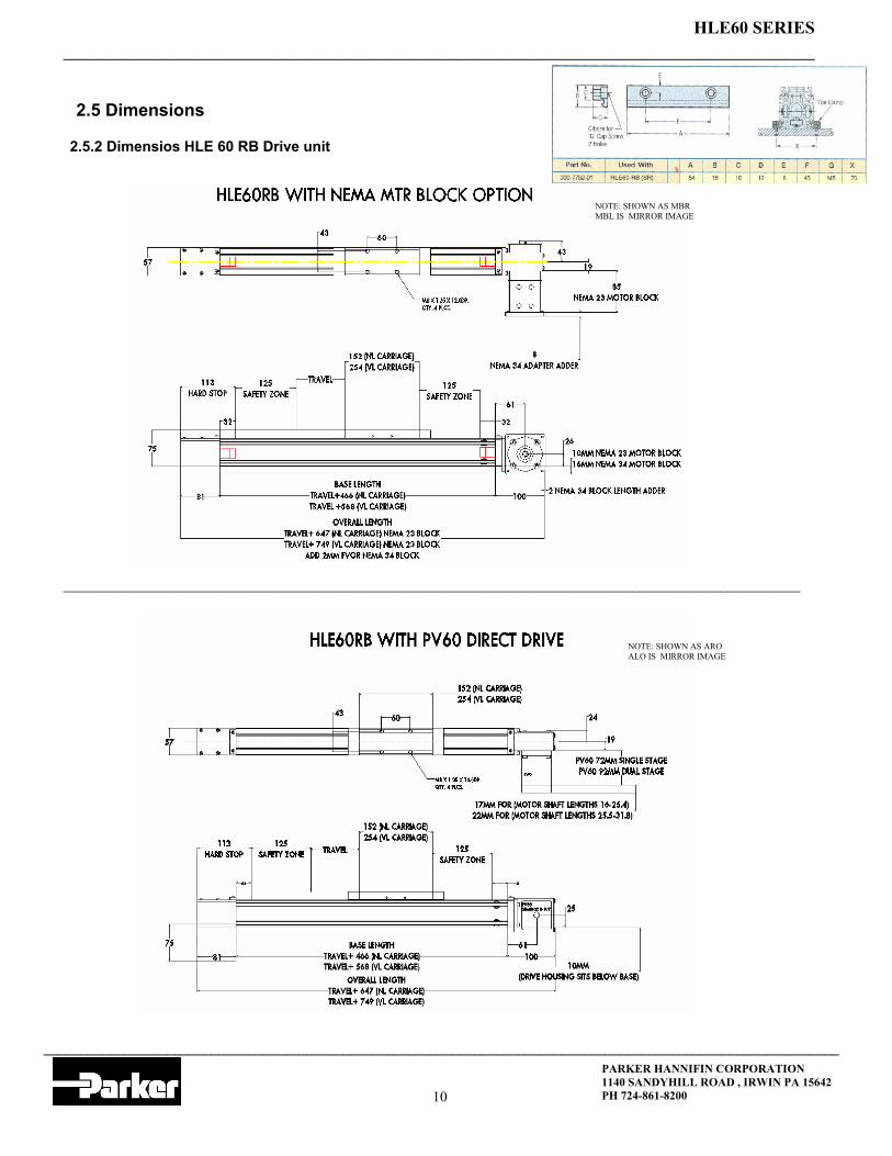
2.5 Dimensions
2.5.2 Dimensios HLE 60 RB Drive unit
_____________________________________________________________________________________________________
4.6.6 R
NOTE: SHOWN AS MBR MBL IS MIRROR IMAGE
NOTE: SHOWN AS ARO ALO IS MIRROR IMAGE

_______________________________________________________________________________________________________
_____________________________________________________________________________________________________________
HLE60 SERIES
PARKER HANNIFIN CORPORATION 1140 SANDYHILL ROAD , IRWIN PA 15642 PH 724-861-8200 11
2.5 Dimensions 2.5.1 Dimensios HLE 60 SR Drive unit
_____ ______________
NOTE: SHOWN AS MBR MBL IS MIRROR IMAGE
NOTE: SHOWN AS ARO ALO IS MIRROR IMAGE
_______________________________________________________________________________________________________
_____________________________________________________________________________________________________________
HLE60 SERIES
PARKER HANNIFIN CORPORATION 1140 SANDYHILL ROAD , IRWIN PA 15642 PH 724-861-8200 12
_______________________________________________________________________________________________________
_____________________________________________________________________________________________________________
HLE60 SERIES
PARKER HANNIFIN CORPORATION 1140 SANDYHILL ROAD , IRWIN PA 15642 PH 724-861-8200 13

_______________________________________________________________________________________________________
_____________________________________________________________________________________________________________
HLE60 SERIES
PARKER HANNIFIN CORPORATION 1140 SANDYHILL ROAD , IRWIN PA 15642 PH 724-861-8200 14

_______________________________________________________________________________________________________
_____________________________________________________________________________________________________________
HLE60 SERIES
PARKER HANNIFIN CORPORATION 1140 SANDYHILL ROAD , IRWIN PA 15642 PH 724-861-8200 15

_______________________________________________________________________________________________________
_____________________________________________________________________________________________________________
HLE60 SERIES
PARKER HANNIFIN CORPORATION 1140 SANDYHILL ROAD , IRWIN PA 15642 PH 724-861-8200 16

_______________________________________________________________________________________________________
_____________________________________________________________________________________________________________
HLE60 SERIES
PARKER HANNIFIN CORPORATION 1140 SANDYHILL ROAD , IRWIN PA 15642 PH 724-861-8200 17
4.5.2 Replacing timing belt
1. Remove end caps (item#6) 2. Remove strip seal clamps(item#2) 3. Remove strip seal (item#1) 4. Remove cover plates (items#3,4,5) 5. Remove belt clamps (item#7) 6. Remove belt (item#8) 7. Measure existing belt (If you do not have old belt see pages 19 and 29) 8. Replace with belt of same length 9. Align/track and tension belt with tensioning screws (item#9) Run carriage from end to end repeatedly and center the belt on pulley. 10. Use tension meter and values on next page for proper tensioning.

_______________________________________________________________________________________________________
_____________________________________________________________________________________________________________
HLE60 SERIES
PARKER HANNIFIN CORPORATION 1140 SANDYHILL ROAD , IRWIN PA 15642 PH 724-861-8200 18
Belt tension measuring device RSM The RSM belt tension measuring device calculates the oscillation frequency of the free running belt length. This is a very fast and easy method of tensioning any type of timing belt. The belt tension measuring device can be obtained through Parker (Part. No. 003-7112-01).
4.5.3 Measuring timing belt tension
Move carriage to far end of travel. Measure tension/frequency at mid point of belt span.

_______________________________________________________________________________________________________
_____________________________________________________________________________________________________________
HLE60 SERIES
PARKER HANNIFIN CORPORATION 1140 SANDYHILL ROAD , IRWIN PA 15642 PH 724-861-8200 19
4.6.1 Checking carriage play on HLE 60 RB
1. Remove the load from the load attachment plate. 2. If equipped with a steel strip cover - remove it 3. Remove timing belt from carriage:
Note Carriage play is when one can grab the load attachment plate and find movement (side to
side or up and down) when applying moderate forces. Check for improper adjustment or worn carriage wheels.
Danger
On vertical axis units, secure the carriage to prevent movement. When timing belt is discon-nected from carriage, it will fall due to gravity if not supported. This can result in dam-age to people or property.
4. Visually check to ensure all wheels are in contact with rail guides over the complete travel. 5. To check wheel pressure against profile guides; prevent wheels from turning using your index finger; wheels should stop rotating when applying minimal force against them. The carriage should feel
smooth but tight throughout its travel.
4.6.2 Adjusting carriage wheels HLE 60 RB
Carriages are designed with both concentric and eccentric wheels located on three sides of carriage body. Fixed or concentric wheels require no adjustment. Eccentric wheels are equipped with an off-set bushing, and when adjusted properly, remove excess play between carriage and profile.
Remove steel strip seal Remove timing belt from carriage. Remove Tension end assembly Remove carriage Clean inside surfaces of profile. Adjust eccentric bushing with a 10 mm socket wrench
in small stages until the carriage can be pushed freely and without play through the HLE profile. Proper adjustment has been achieved when, with minimal pressure from your finger, the wheel can be stopped from rotating.
Note: Concentric wheels should be carry load in normal direction. Eccentric wheels are for preloading the carriage in profile. Repeat step 5 as necessary, until carriage adjustment
is correct. And all wheels are in contact with profile Note: Extended carriage has 4 additional eccentric
wheels per side and will alternate preload one up and one down against profile surfaces

_______________________________________________________________________________________________________
_____________________________________________________________________________________________________________
HLE60 SERIES
PARKER HANNIFIN CORPORATION 1140 SANDYHILL ROAD , IRWIN PA 15642 PH 724-861-8200 20
4.6.3 Checking carriage play on HLE 60SR
Remove the load from the load attachment plate. If equipped with a steel strip cover - remove it: Remove timing belt from carriage: (see 4.5.2).
Visually check for rust or corrosion of the steel rail system. If corrosion exists, completely changing out both steel rail and bearing block assembly Push the carriage over the complete travel while observing the area where the linear bearing block meets the steel rail. The carriage should feel smooth but tight throughout the travel. Lubricate the bearing block and check for excessive leakage at end seals. Excessive side to side movement indicates wear between linear bearing block and steel rail. Completely change out both steel rail and bearing block assembly . There are no adjustments to linear bearing blocks to compensate for wear.
Danger
On vertical axis units, secure the carriage to prevent movement. When timing belt is discon-nected from carriage, it will fall due to gravity if not supported. This can result in dam-age to people or property.
Note Carriage play is when one can grab the load attachment plate and find movement (side to
side or up and down) when applying moderate forces. Check for a worn out linear bearing block or wear on the steel rail.
4.6.4 Changing bearing blocks HLE 60 SR
General
Linear bearing blocks consist of re-circulating (one string on each side) ball bearings captured within the block. Bearing blocks are sealed against the square steel rail and lubricated through a fitting located at the end of each block. Lubrication is required. Although linear bearing blocks are capable of operating at a maxi-mum temperature of 248°F (120°C) and continuously at 212°F (100°C), the timing belt can only withstand environmental temperatures between 40°F (-40°C) to 178°F (+80°C).
Warning
If checking for bearing block damage while carriage is in motion within profile, care should be taken to prevent injury. If possible, move the carriage manually (best done if motor and gearbox are removed and drive unit is horizontal). If using motor, operate drive unit with jog button at low speed (< 1m/min).
Note
When removing bearing block from guide rail observe reference markings on both block and rail. Bearing blocks are ground on one side (its ref. mark) and rails have arrows embossed on the top of the rail indicating its ref. mark. During re-assembly it is important to match these reference marks (see below).

_______________________________________________________________________________________________________
_____________________________________________________________________________________________________________
HLE60 SERIES
PARKER HANNIFIN CORPORATION 1140 SANDYHILL ROAD , IRWIN PA 15642 PH 724-861-8200 21
4.6.6 Changing steel square rail
Remove carriage Using a 4mm allen wrench remove all bolts washers located on top of square rail. Lift rail up and out through access slot in profile Clean inside of profile. Position new rail within profile (ref. arrow mark side of rail against ledge running the length of profile) and re-Install hardware from step #2 into new square rail (do not tighten). Push rail against ledge while tightening all bolts.
4.6.4 Changing bearing blocks HLE 60 SR (cont.)
Remove carriage from steel rail guide Place on a clean surface. Remove socket head cap screws from top of carriage. Lift old bearing block(item#2) from carriage frame. Position replacement block on carriage (note reference mark on side of block (machined ground side).When re- inserting carriage this side should align with rail side that is banked against profile edge Thread in socket head screws with screw retention (Loc-tite) but do not tighten. Repeat steps 3 through 5 for second bearing block. Clean inside of linear drive profile and apply grease to steel rail Guide carriage assembly onto steel rail and insert into profile
NOTE: Use only LITHIUM 12 HYDROXYSTEARATE SOAP BASE(SHELL ALVANIA RS2) containing additives to en-hance oxidation resistance and rust protection. CAUTION: Never mix petroleum base, with synthetic base lubricants. For special or sever service conditions, consult factory.
4.6.5 Lubrication of bearing block
Remove steel strip seal Center carriage in relation to travel. Remove timing belt (see 4.5.2) from carriage . Using a grease gun, pump 3 shots of grease into fitting. Repeat steps 3 & 4 on opposite side of carriage for second bearing block. Re-install timing belt (see 4.5.2). Replace steel strip seal
_______________________________________________________________________________________________________
_____________________________________________________________________________________________________________
HLE60 SERIES
PARKER HANNIFIN CORPORATION 1140 SANDYHILL ROAD , IRWIN PA 15642 PH 724-861-8200 22
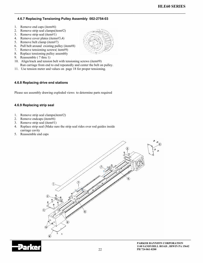
4.6.7 Replacing Tensioning Pulley Assembly 002-2754-03
4.6.8 Replacing drive end stations
1. Remove end caps (item#6) 2. Remove strip seal clamps(item#2) 3. Remove strip seal (item#1) 4. Remove cover plates (items#3,4) 5. Remove belt clamp (item#7) 6. Pull belt around existing pulley (item#8) 7. Remove tensioning screws( item#9) 8. Replace tensioning pulley assembly 9. Reassemble ( 7 thru 1) 10. Align/track and tension belt with tensioning screws (item#9) Run carriage from end to end repeatedly and center the belt on pulley. 11. Use tension meter and values on page 18 for proper tensioning.
Please see assembly drawing exploded views to determine parts required
4.6.9 Replacing strip seal
1. Remove strip seal clamps(item#2) 2. Remove endcaps (item#6) 3. Remove strip seal (item#1) 4. Replace strip seal (Make sure the strip seal rides over rod guides inside
carriage cavity 5. Reassemble end caps

_______________________________________________________________________________________________________
_____________________________________________________________________________________________________________
HLE60 SERIES
PARKER HANNIFIN CORPORATION 1140 SANDYHILL ROAD , IRWIN PA 15642 PH 724-861-8200 23
4.6.10 Double Axis General
Double axes are generally shipped as two single axis assemblies. Link shafts with coupling sets are disman-tled for ease of shipping. The couplings only allow for minimal misalignment and offset angles between the two axis.( care must be taken when mounting dual axis to assure the axial alignment is maintained.
Clamping style couplings provide a method of adjusting carriage position that would otherwise not be possi-ble with a fixed keyway design.
4.6.10 Aligning carriages OF DUAL AXIS UNIT
Refer to section 1 .5 for initial set up directions. of dual axis on page 13.
Once mounted and aligned loosen one coupling on the x� axis.( non motor mounted axis) 1. Move carriage of motor driven axis to end of travel and let rest against bumper. 2. Move carriage of x� axis to same relative location on its axis. 3. Tighten the coupling to the specified torque( ( 2.2 N-M)

_______________________________________________________________________________________________________
_____________________________________________________________________________________________________________
HLE60 SERIES
PARKER HANNIFIN CORPORATION 1140 SANDYHILL ROAD , IRWIN PA 15642 PH 724-861-8200 24
HLE60 GEN2 Configurable
HLE60 RB NL 1000 DA0000 E
ROLLER BELT RB SQUARE RAIL SR
STANDARD CARRIAGE NL EXTENDED CARRIAGE VL
IDLER UNIT M SINGLE AXIS E
DUAL AXIS UNIT D
TRAVEL ( MAX "NL" CARRIAGE=3000mm) XXXX
( MAX "VL" CARRIAGE=2900mm)
NO DRIVE SHAFT SINGLE AXIS DA0000 DUAL AXIS UNIT XXXX=MM CTR. TO CTR. 200MM
MIN/1500MM MAX. DAXXXX
DUAL AXIS UNIT XXXX=MM CTR. TO CTR. 200MM MIN/1500MM MAX. W COVERED LINK SHAFT DCXXXX
IDLER UNIT WOO
SHAFT RIGHT WRO SHAFT LEFT WLO
DUAL SHAFT WBO Gearhead RIGHT ARO
Gearhead LEFT ALO Gearhead RIGHT SHAFT LEFT ARW Gearhead LEFT SHAFT RIGHT ALW
MOTOR BLOCK RIGHT MBR MOTOR BLOCK LEFT MBL
MOTOR BLOCK RIGHT SHAFT LEFT MRW MOTOR BLOCK LEFT SHAFT RIGHT MLW DUAL AXIS Gearhead DRIVE RIGHT DAR DUAL AXIS Gearhead DRIVE LEFT DAL DUAL AXIS MOTOR BLOXK RIGHT DMR DUAL AXIS MOTOR BLOCK LEFT DML
MBL

_______________________________________________________________________________________________________
_____________________________________________________________________________________________________________
HLE60 SERIES
PARKER HANNIFIN CORPORATION 1140 SANDYHILL ROAD , IRWIN PA 15642 PH 724-861-8200 25
HLE60 GEN2 Configurable
SP1 G12NN K21 ZA H1 LHO
SP19 DRIVE HOUSING FOR PV60-FN SP20 IDLER UNIT SP21 NO MOTOR BLOCK SP22 MOTOR BLOCK NEMA23 W 0.375" BORE COUPLING SP23 MOTOR BLOCK NEMA23 W 0.25" BORE COUPLING SP24 MOTOR BLOCK NEMA34 W 0.375" BORE COUPLING SP25 MOTOR BLOCK NEMA34 W 0.50" BORE COUPLING SP28 MOTOR BLOCK NEMA23 NO COUPLING SP29 MOTOR BLOCK NEMA34 NO COUPLING SP30 MOTOR BLOCK NEO70 W 11.0MM BORE COUPLING
LHO NO LIMIT SWITCHES
LH3 THREE NPN PROX SWITCHES 10V-30 VDC LH4 THREE PNP PROX SWITCHES 10-30 VDC
ZA UNIT WITH STRIP SEAL ZB UNIT WITHOUT STRIP SEAL
K00-HLE60 NO MOTOR KIT K21-HLE60 MOTOR KIT LV23/HV23/OS23/ES23/VS23 K22-HLE60 MOTOR KIT BE23X K23-HLE60 MOTOR KIT SM23/SE23 K24-HLE60 MOTOR KIT LV34/HV34 K25-HLE60 MOTOR KIT BE34/NO34X/JO34X/TS31/TS32 K26-HLE60 MOTOR KIT RS34/ES34 K27-HLE60 MOTOR KIT NO70/JO70 K28-HLE60 MOTOR KIT SMB60
G0 NO GEARBOX REQUIRES MBR/MBL/MRW/MLW G1 CUSTOMER SUPPLIED GEARHEAD
G1203 PV60 GEARHEAD 3:1 RATIO G1205 PV60 GEARHEAD 5:1 RATIO G1210 PV60 GEARHEAD 10:1 RATIO G1215 PV60 GEARHEAD 15:1 RATIO G1225 PV60 GEARHEAD 25:1 RATIO
H1 NORMAL ORIENTATION CARRIAGE UP H2 INVERTED ORIENTATION CARRIAGE DOWN H3 CARRIAGE ON SIDE DRIVE STATION UP H4 CARRIAGE ON ITS SIDE DRIVE STATION DOWN

_______________________________________________________________________________________________________
_____________________________________________________________________________________________________________
HLE60 SERIES
PARKER HANNIFIN CORPORATION 1140 SANDYHILL ROAD , IRWIN PA 15642 PH 724-861-8200 26
HLE60RB ASSEMBLY COMPONENTS
HLE 60RB REQUIRED BELT LENGTH P/N 003-1860-01 NL/VL/SL CARRIAGE 1272MM + (2 X TRAVEL) BASE LENGTH P/N 100-0340-01 NL CARRIAGE 466 MM +TRAVEL VL CARRIAGE 568 MM +TRAVEL SL CARRIAGE 314 MM+TRAVEL+ SPECIAL CARRIAGE LENGTH STRIP SEAL P/N 003-1879-01 NL CARRIAGE 480 MM +TRAVEL VL CARRIAGE 582 MM +TRAVEL SL CARRIAGE 328 MM+TRAVEL+ SPECIAL CARRIAGE LENGTH
_______________________________________________________________________________________________________
_____________________________________________________________________________________________________________
HLE60 SERIES
PARKER HANNIFIN CORPORATION 1140 SANDYHILL ROAD , IRWIN PA 15642 PH 724-861-8200 27
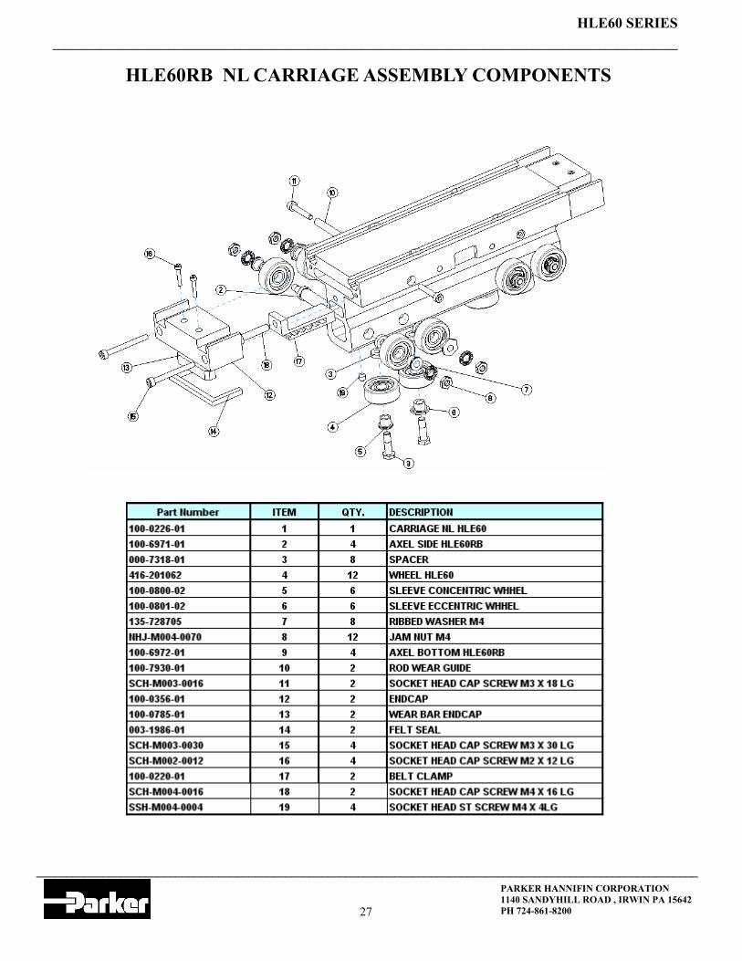
HLE60RB NL CARRIAGE ASSEMBLY COMPONENTS

_______________________________________________________________________________________________________
_____________________________________________________________________________________________________________
HLE60 SERIES
PARKER HANNIFIN CORPORATION 1140 SANDYHILL ROAD , IRWIN PA 15642 PH 724-861-8200 28
HLE60RB VL CARRIAGE ASSEMBLY COMPONENTS

_______________________________________________________________________________________________________
_____________________________________________________________________________________________________________
HLE60 SERIES
PARKER HANNIFIN CORPORATION 1140 SANDYHILL ROAD , IRWIN PA 15642 PH 724-861-8200 29
ARO/ALO-HLE60RB DRIVE END ASSEMBLY

_______________________________________________________________________________________________________
_____________________________________________________________________________________________________________
HLE60 SERIES
PARKER HANNIFIN CORPORATION 1140 SANDYHILL ROAD , IRWIN PA 15642 PH 724-861-8200 30
ARW/ALW-HLE60RB DRIVE END ASSEMBLY

_______________________________________________________________________________________________________
_____________________________________________________________________________________________________________
HLE60 SERIES
PARKER HANNIFIN CORPORATION 1140 SANDYHILL ROAD , IRWIN PA 15642 PH 724-861-8200 31
MBR/MBL-HLE60RB DRIVE END ASSEMBLY

_______________________________________________________________________________________________________
_____________________________________________________________________________________________________________
HLE60 SERIES
PARKER HANNIFIN CORPORATION 1140 SANDYHILL ROAD , IRWIN PA 15642 PH 724-861-8200 32
MRW/MLW-HLE60RB DRIVE END ASSEMBLY

_______________________________________________________________________________________________________
_____________________________________________________________________________________________________________
HLE60 SERIES
PARKER HANNIFIN CORPORATION 1140 SANDYHILL ROAD , IRWIN PA 15642 PH 724-861-8200 33
WBO-HLE60RB DRIVE END ASSEMBLY

_______________________________________________________________________________________________________
_____________________________________________________________________________________________________________
HLE60 SERIES
PARKER HANNIFIN CORPORATION 1140 SANDYHILL ROAD , IRWIN PA 15642 PH 724-861-8200 34
WRO/WLO-HLE60RB-DRIVE END ASSEMBLY

_______________________________________________________________________________________________________
_____________________________________________________________________________________________________________
HLE60 SERIES
PARKER HANNIFIN CORPORATION 1140 SANDYHILL ROAD , IRWIN PA 15642 PH 724-861-8200 35
002-2754-01 HLE60RB TENSION END ASSEMBLY

_______________________________________________________________________________________________________
_____________________________________________________________________________________________________________
HLE60 SERIES
PARKER HANNIFIN CORPORATION 1140 SANDYHILL ROAD , IRWIN PA 15642 PH 724-861-8200 36
HLE60SR ASSEMBLY COMPONENTS
HLE 60SR REQUIRED BELT LENGTH P/N 003-1860-01 NL/VL/SL CARRIAGE 1256MM + (2 X TRAVEL) BASE LENGTH P/N 100-1778-01 NL CARRIAGE 448 MM +TRAVEL VL CARRIAGE 550 MM +TRAVEL SL CARRIAGE 297 MM+TRAVEL+ SPECIAL CARRIAGE LENGTH RAIL LENGTH P/N 100-1777-01 NL CARRIAGE 444 MM +TRAVEL VL CARRIAGE 546 MM +TRAVEL SL CARRIAGE 291 MM+TRAVEL+ SPECIAL CARRIAGE LENGTH STRIP SEAL P/N 003-1879-01 NL CARRIAGE 464 MM +TRAVEL VL CARRIAGE 566 MM +TRAVEL SL CARRIAGE 313 MM+TRAVEL+ SPECIAL CARRIAGE LENGTH

_______________________________________________________________________________________________________
_____________________________________________________________________________________________________________
HLE60 SERIES
PARKER HANNIFIN CORPORATION 1140 SANDYHILL ROAD , IRWIN PA 15642 PH 724-861-8200 37
HLE60SR NL CARRIAGE ASSEMBLY COMPONENTS
_______________________________________________________________________________________________________
_____________________________________________________________________________________________________________
HLE60 SERIES
PARKER HANNIFIN CORPORATION 1140 SANDYHILL ROAD , IRWIN PA 15642 PH 724-861-8200 38
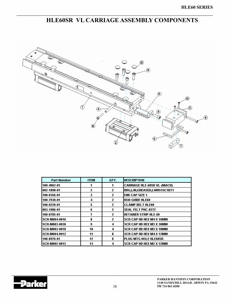
HLE60SR VL CARRIAGE ASSEMBLY COMPONENTS

_______________________________________________________________________________________________________
_____________________________________________________________________________________________________________
HLE60 SERIES
PARKER HANNIFIN CORPORATION 1140 SANDYHILL ROAD , IRWIN PA 15642 PH 724-861-8200 39
ARO/ALO-HLE60SR-DRIVE END ASSEMBLY

_______________________________________________________________________________________________________
_____________________________________________________________________________________________________________
HLE60 SERIES
PARKER HANNIFIN CORPORATION 1140 SANDYHILL ROAD , IRWIN PA 15642 PH 724-861-8200 40
ARW/ALW -HLE60SR DRIVE END ASSEMBLY

_______________________________________________________________________________________________________
_____________________________________________________________________________________________________________
HLE60 SERIES
PARKER HANNIFIN CORPORATION 1140 SANDYHILL ROAD , IRWIN PA 15642 PH 724-861-8200 41
MBR/MBL -HLE60SR-DRIVE END ASSEMBLY
_______________________________________________________________________________________________________
_____________________________________________________________________________________________________________
HLE60 SERIES
PARKER HANNIFIN CORPORATION 1140 SANDYHILL ROAD , IRWIN PA 15642 PH 724-861-8200 42
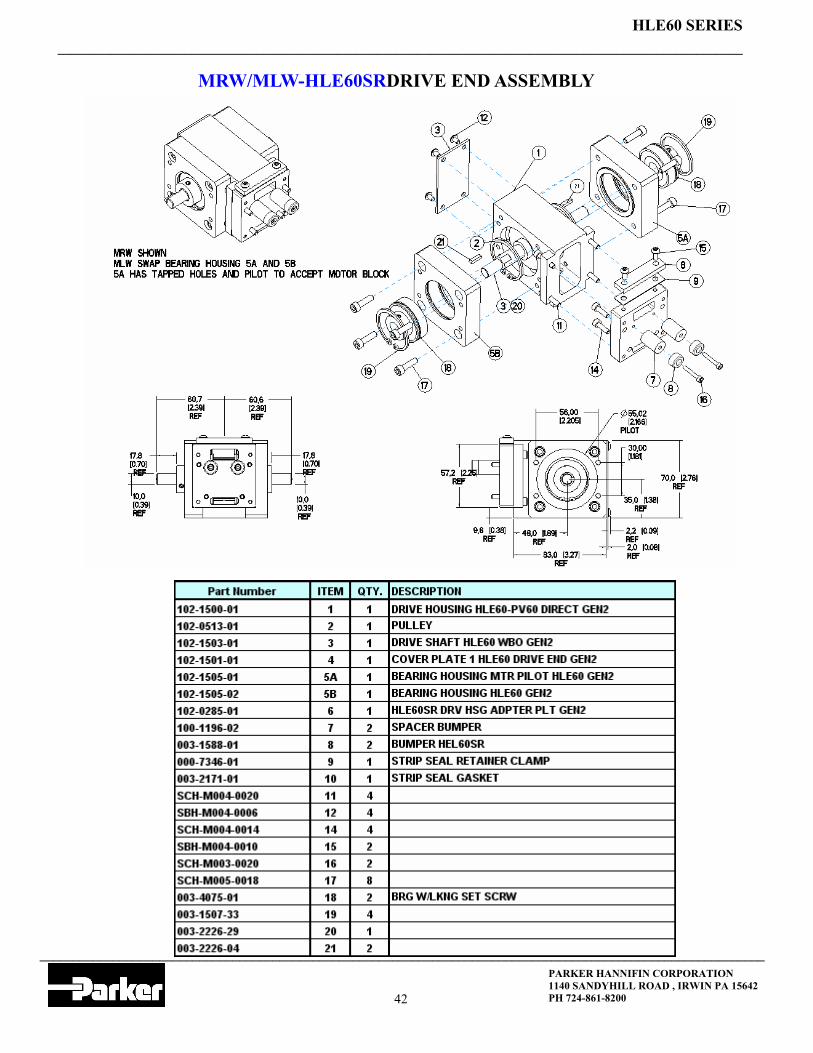
MRW/MLW-HLE60SRDRIVE END ASSEMBLY

_______________________________________________________________________________________________________
_____________________________________________________________________________________________________________
HLE60 SERIES
PARKER HANNIFIN CORPORATION 1140 SANDYHILL ROAD , IRWIN PA 15642 PH 724-861-8200 43
WBO-HLE60SR DRIVE END ASSEMBLY
_______________________________________________________________________________________________________
_____________________________________________________________________________________________________________
HLE60 SERIES
PARKER HANNIFIN CORPORATION 1140 SANDYHILL ROAD , IRWIN PA 15642 PH 724-861-8200 44
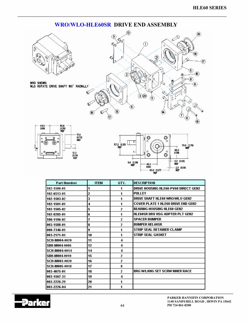
WRO/WLO-HLE60SR DRIVE END ASSEMBLY

_______________________________________________________________________________________________________
_____________________________________________________________________________________________________________
HLE60 SERIES
PARKER HANNIFIN CORPORATION 1140 SANDYHILL ROAD , IRWIN PA 15642 PH 724-861-8200 45
002-2754-02 HLE60SR TENSION END ASSEMBLY

_______________________________________________________________________________________________________
_____________________________________________________________________________________________________________
HLE60 SERIES
PARKER HANNIFIN CORPORATION 1140 SANDYHILL ROAD , IRWIN PA 15642 PH 724-861-8200 46
PV60 Gearbox Technical Information
_______________________________________________________________________________________________________
_____________________________________________________________________________________________________________
HLE60 SERIES
PARKER HANNIFIN CORPORATION 1140 SANDYHILL ROAD , IRWIN PA 15642 PH 724-861-8200 47
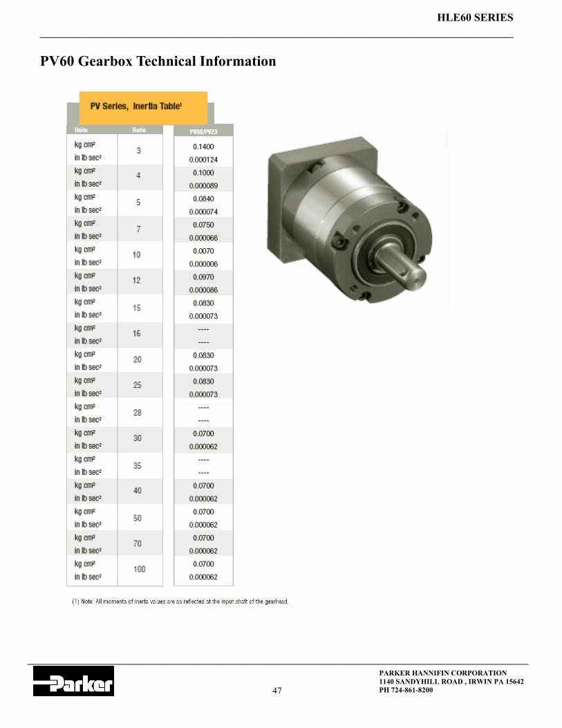
PV60 Gearbox Technical Information

_______________________________________________________________________________________________________
_____________________________________________________________________________________________________________
HLE60 SERIES
PARKER HANNIFIN CORPORATION 1140 SANDYHILL ROAD , IRWIN PA 15642 PH 724-861-8200 48
PV60 Gearbox Technical Information
PV60-FN Load vs. Speed
_______________________________________________________________________________________________________
_____________________________________________________________________________________________________________
HLE60 SERIES
PARKER HANNIFIN CORPORATION 1140 SANDYHILL ROAD , IRWIN PA 15642 PH 724-861-8200 49
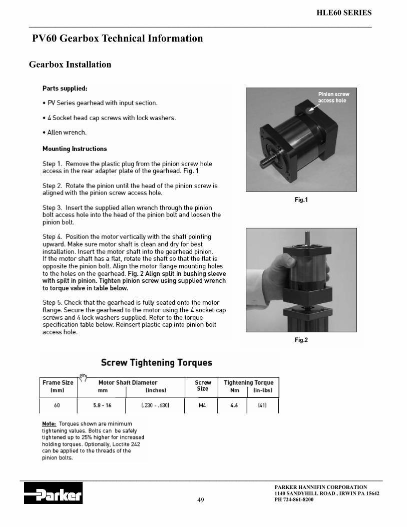
PV60 Gearbox Technical Information
Gearbox Installation

_______________________________________________________________________________________________________
_____________________________________________________________________________________________________________
HLE60 SERIES
PARKER HANNIFIN CORPORATION 1140 SANDYHILL ROAD , IRWIN PA 15642 PH 724-861-8200 50


![Unit B01 – Motion in One Dimension [UNAUTHORIZED COPYING OR USE OF ANY PART OF ANY ONE OF THESE SLIDES IS ILLEGAL.]](https://img.pdfslide.us/doc/110x75/56649e865503460f94b89954/unit-b01-motion-in-one-dimension-unauthorized-copying-or-use-of-any-part.jpg)