Embed Size (px)
Citation preview

Copyright Hitachi, 2016 - 2020 Version 9.0 Page 1 of 22 Hitachi Public Material – May be reproduced only in its original entirety (without revision).
Hitachi Virtual Storage Platform (VSP) Encryption Adapter
FIPS 140-2 Non-Proprietary Cryptographic Module Security Policy
Version: 9.0
Date: March 16, 2020
Prepared by: Hitachi, Ltd.
Copyright Hitachi, 2016 - 2020 Version 9.0 Page 2 of 22 Hitachi Public Material – May be reproduced only in its original entirety (without revision).
Table of Contents
1 Introduction .................................................................................................................. 4
1.1 Hardware and Physical Cryptographic Boundary ......................................................................... 5
1.2 Firmware and Logical Cryptographic Boundary ........................................................................... 8
1.3 Mode of Operation ....................................................................................................................... 9
2 Cryptographic Functionality ......................................................................................... 10
2.1 Critical Security Parameters .......................................................................................................11
3 Roles, Authentication and Services .............................................................................. 12
3.1 Assumption of Roles ...................................................................................................................12
3.2 Authentication Methods ............................................................................................................13
3.3 Services .......................................................................................................................................14
4 Self-tests ..................................................................................................................... 16
5 Physical Security Policy ................................................................................................ 17
6 Operational Environment ............................................................................................ 18
7 Mitigation of Other Attacks Policy................................................................................ 18
8 Security Rules and Guidance ........................................................................................ 19
8.1 Crypto Officer Guidance .............................................................................................................19
8.2 User Guidance ............................................................................................................................20
9 Design Assurance Policy ............................................................................................... 21
9.1 Configuration Management Overview .......................................................................................21
9.2 Installation, Initialization, and start-up Overview ......................................................................21
9.3 Secure Delivery and Operation Overview ..................................................................................21
10 References and Definitions .......................................................................................... 22
Copyright Hitachi, 2016 - 2020 Version 9.0 Page 3 of 22 Hitachi Public Material – May be reproduced only in its original entirety (without revision).
List of Tables
Table 1 – Cryptographic Module Configurations .......................................................................................... 4
Table 2 – Security Level of Security Requirements ....................................................................................... 4
Table 3 – Ports and Interfaces ...................................................................................................................... 9
Table 4 – Approved and CAVP Validated Cryptographic Functions ............................................................ 10
Table 5 – Critical Security Parameters (CSPs) ............................................................................................. 11
Table 6 – Roles Description ......................................................................................................................... 12
Table 7 – Authentication Description ......................................................................................................... 13
Table 8 – Authenticated Services ................................................................................................................ 14
Table 9 – Unauthenticated Services ........................................................................................................... 14
Table 10 – CSP Access Rights within Services ............................................................................................. 15
Table 11 – Power Up Self-tests ................................................................................................................... 16
Table 12 – Conditional Self-tests ................................................................................................................ 17
Table 13 – Physical Security Inspection Guidelines .................................................................................... 17
Table 14 – References ................................................................................................................................. 22
Table 15 – Acronyms and Definitions ......................................................................................................... 22
List of Figures
Figure 1 – Front Side of the Module ............................................................................................................. 5
Figure 2 – Back Side of the Module .............................................................................................................. 5
Figure 3 – Left Side of the Module ................................................................................................................ 5
Figure 4 – Right Side of the Module ............................................................................................................. 6
Figure 5 – Up Side of the Module ................................................................................................................. 6
Figure 6 – Bottom Side of the Module .......................................................................................................... 7
Figure 7 – Module Block Diagram ................................................................................................................. 8
Copyright Hitachi, 2016 - 2020 Version 9.0 Page 4 of 22 Hitachi Public Material – May be reproduced only in its original entirety (without revision).
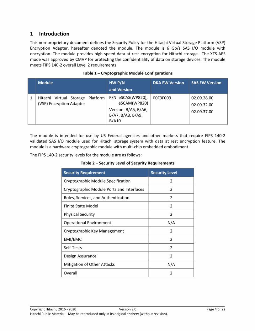
1 Introduction
This non-proprietary document defines the Security Policy for the Hitachi Virtual Storage Platform (VSP) Encryption Adapter, hereafter denoted the module. The module is 6 Gb/s SAS I/O module with encryption. The module provides high speed data at rest encryption for Hitachi storage. The XTS-AES mode was approved by CMVP for protecting the confidentiality of data on storage devices. The module meets FIPS 140-2 overall Level 2 requirements.
Table 1 – Cryptographic Module Configurations
Module HW P/N
and Version
DKA FW Version SAS FW Version
1 Hitachi Virtual Storage Platform (VSP) Encryption Adapter
P/N: eSCAS(WP820), eSCAM(WP820)
Version: B/A5, B/A6, B/A7, B/A8, B/A9, B/A10
00F3F003 02.09.28.00
02.09.32.00
02.09.37.00
The module is intended for use by US Federal agencies and other markets that require FIPS 140-2 validated SAS I/O module used for Hitachi storage system with data at rest encryption feature. The module is a hardware cryptographic module with multi-chip embedded embodiment.
The FIPS 140-2 security levels for the module are as follows:
Table 2 – Security Level of Security Requirements
Security Requirement Security Level
Cryptographic Module Specification 2
Cryptographic Module Ports and Interfaces 2
Roles, Services, and Authentication 2
Finite State Model 2
Physical Security 2
Operational Environment N/A
Cryptographic Key Management 2
EMI/EMC 2
Self-Tests 2
Design Assurance 2
Mitigation of Other Attacks N/A
Overall 2
Copyright Hitachi, 2016 - 2020 Version 9.0 Page 5 of 22 Hitachi Public Material – May be reproduced only in its original entirety (without revision).
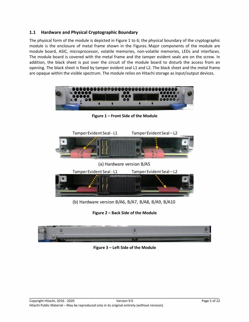
1.1 Hardware and Physical Cryptographic Boundary
The physical form of the module is depicted in Figure 1 to 6; the physical boundary of the cryptographic module is the enclosure of metal frame shown in the Figures. Major components of the module are module board, ASIC, microprocessor, volatile memories, non-volatile memories, LEDs and interfaces. The module board is covered with the metal frame and the tamper evident seals are on the screw. In addition, the black sheet is put over the circuit of the module board to disturb the access from an opening. The black sheet is fixed by tamper evident seal L1 and L2. The black sheet and the metal frame are opaque within the visible spectrum. The module relies on Hitachi storage as input/output devices.
Figure 1 – Front Side of the Module
Figure 2 – Back Side of the Module
Figure 3 – Left Side of the Module
(a) Hardware version B/A5
Tamper Evident Seal - L1 Tamper Evident Seal – L2
(b) Hardware version B/A6, B/A7, B/A8, B/A9, B/A10
Tamper Evident Seal - L1 Tamper Evident Seal – L2
Copyright Hitachi, 2016 - 2020 Version 9.0 Page 6 of 22 Hitachi Public Material – May be reproduced only in its original entirety (without revision).
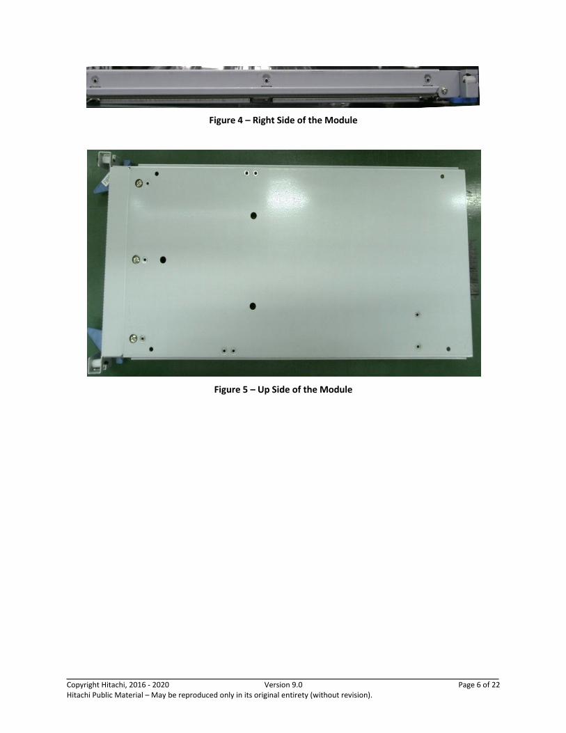
Figure 4 – Right Side of the Module
Figure 5 – Up Side of the Module
Copyright Hitachi, 2016 - 2020 Version 9.0 Page 7 of 22 Hitachi Public Material – May be reproduced only in its original entirety (without revision).
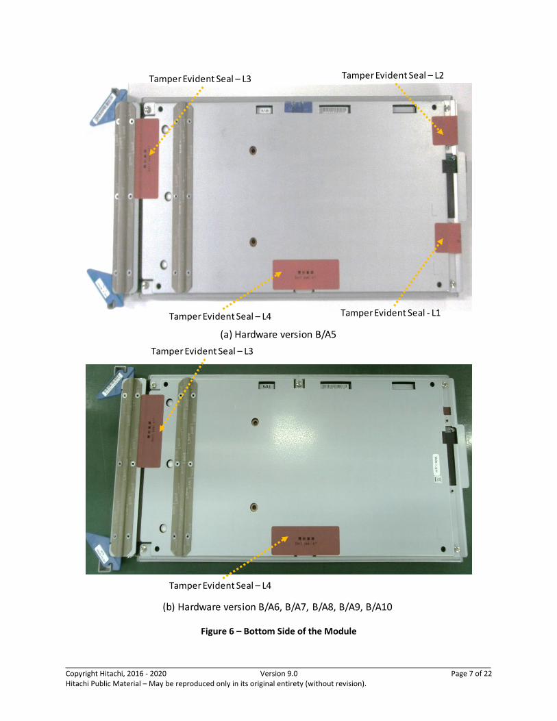
Figure 6 – Bottom Side of the Module
Tamper Evident Seal - L1
Tamper Evident Seal – L2Tamper Evident Seal – L3
Tamper Evident Seal – L4
Tamper Evident Seal – L3
Tamper Evident Seal – L4
(b) Hardware version B/A6, B/A7, B/A8, B/A9, B/A10
(a) Hardware version B/A5
Copyright Hitachi, 2016 - 2020 Version 9.0 Page 8 of 22 Hitachi Public Material – May be reproduced only in its original entirety (without revision).
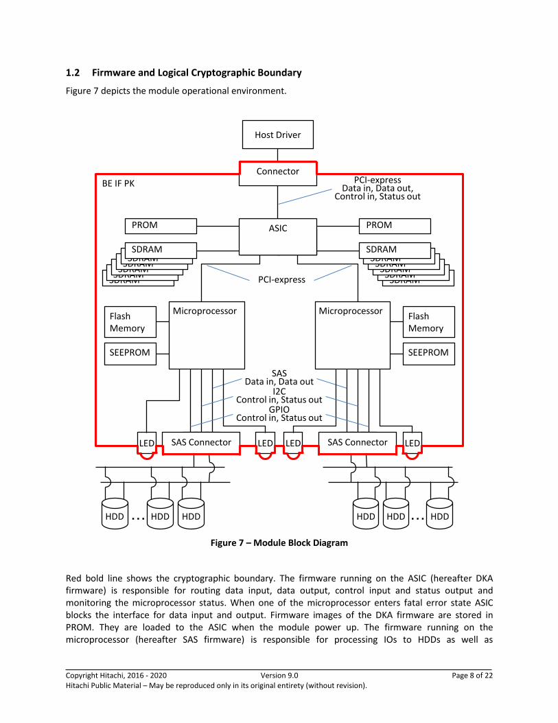
1.2 Firmware and Logical Cryptographic Boundary
Figure 7 depicts the module operational environment.
Figure 7 – Module Block Diagram
Red bold line shows the cryptographic boundary. The firmware running on the ASIC (hereafter DKA firmware) is responsible for routing data input, data output, control input and status output and monitoring the microprocessor status. When one of the microprocessor enters fatal error state ASIC blocks the interface for data input and output. Firmware images of the DKA firmware are stored in PROM. They are loaded to the ASIC when the module power up. The firmware running on the microprocessor (hereafter SAS firmware) is responsible for processing IOs to HDDs as well as
BE IF PK
SDRAMSDRAM
SDRAMSDRAM
SDRAMSDRAM
SDRAMSDRAM
SDRAMSDRAM
SDRAMSDRAM
LR
Flash Memory
SEEPROM
Flash
PROM
Flash
PROM
Flash Memory
SEEPROM
Host Driver
Connector
HDD HDD HDD・・・ HDD HDD HDD・・・
PCI-express
SASData in, Data out
PROM PROM
LED LEDLED LED
GPIOControl in, Status out
I2CControl in, Status out
SAS Connector SAS Connector
PCI-expressData in, Data out,
Control in, Status out
MicroprocessorMicroprocessor
LRASIC

Copyright Hitachi, 2016 - 2020 Version 9.0 Page 9 of 22 Hitachi Public Material – May be reproduced only in its original entirety (without revision).
encrypting/decrypting IOs where applicable. AES and SHA hardware accelerators are integrated into the microprocessor. Firmware images of the SAS firmware are stored in the flash memory. They are loaded to the microprocessor when the module power up. All functions and system initialization are performed by the microprocessor, which is contained within the cryptographic boundary of the module. CSPs are stored in flash memory or SEEPROM.
Table 3 – Ports and Interfaces
Port Description Logical Interface Type
PCI-express plaintext input/output, module control data input, module status data output
- Control in / Status out
- Data in / Data out
GPIO module control data input, module status data output - Control in / Status out
I2C module control data input, module status data output - Control in / Status out
Power 12V power input - Power
SAS cipher text input/output - Data in / Data out
LED module status output - Status out
1.3 Mode of Operation
The module encrypts and decrypts data using only a FIPS-approved mode of operation. It does not have any functional non-approved modes.

Copyright Hitachi, 2016 - 2020 Version 9.0 Page 10 of 22 Hitachi Public Material – May be reproduced only in its original entirety (without revision).
2 Cryptographic Functionality
The module implements the FIPS Approved cryptographic functions listed in the tables below.
Table 4 – Approved and CAVP Validated Cryptographic Functions
Algorithm Description Cert #
AES [NIST SP 800-38A]
Functions: Encryption, Decryption
Modes: ECB
Key sizes: 256 bits #2787
XTS-AES mode
[NIST SP 800-38E]
Functions: Encryption, Decryption
Key sizes: 256 bits #2787
AES Key Wrap/Unwrap
[NIST SP 800-38F]
Functions: Key wrapping/unwrapping; key establishment methodology provides 256 bits of encryption strength
Key sizes: 256 bits #2787
SHA*1 [FIPS 180-4]
Functions: Calculation of HMAC
SHA sizes: SHA-256 #2344
SHA sizes: SHA-1, SHA-224, SHA-384, SHA-512 #2504
HMAC*1 [FIPS 198-1]
Functions: MAC generation
SHA sizes: SHA-256 #1748
SHA sizes: SHA-1, SHA-224, SHA-384, SHA-512 #1889 *1The HMAC-SHA-1, HMAC-SHA-224, HMAC-SHA-384 and HMAC-SHA-512 algorithms (and their
underlying SHA algorithms) have been tested under CAVP, but are not implemented by any service of the module.
Copyright Hitachi, 2016 - 2020 Version 9.0 Page 11 of 22 Hitachi Public Material – May be reproduced only in its original entirety (without revision).
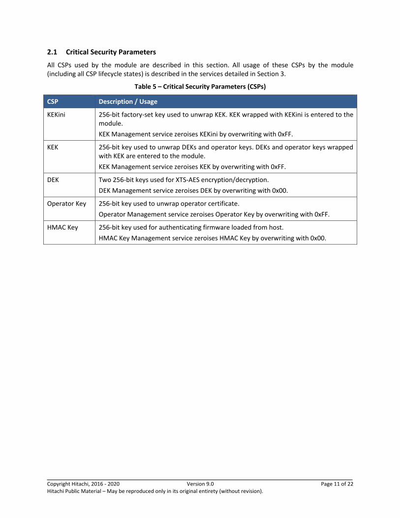
2.1 Critical Security Parameters
All CSPs used by the module are described in this section. All usage of these CSPs by the module (including all CSP lifecycle states) is described in the services detailed in Section 3.
Table 5 – Critical Security Parameters (CSPs)
CSP Description / Usage
KEKini 256-bit factory-set key used to unwrap KEK. KEK wrapped with KEKini is entered to the module.
KEK Management service zeroises KEKini by overwriting with 0xFF.
KEK 256-bit key used to unwrap DEKs and operator keys. DEKs and operator keys wrapped with KEK are entered to the module.
KEK Management service zeroises KEK by overwriting with 0xFF.
DEK Two 256-bit keys used for XTS-AES encryption/decryption.
DEK Management service zeroises DEK by overwriting with 0x00.
Operator Key 256-bit key used to unwrap operator certificate.
Operator Management service zeroises Operator Key by overwriting with 0xFF.
HMAC Key 256-bit key used for authenticating firmware loaded from host.
HMAC Key Management service zeroises HMAC Key by overwriting with 0x00.
Copyright Hitachi, 2016 - 2020 Version 9.0 Page 12 of 22 Hitachi Public Material – May be reproduced only in its original entirety (without revision).
3 Roles, Authentication and Services
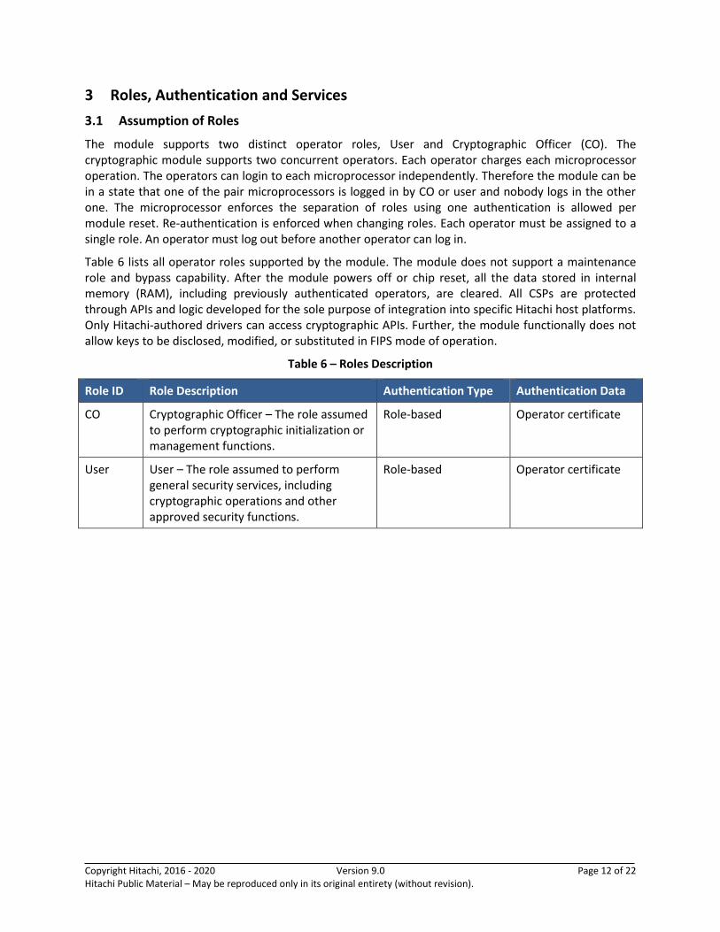
3.1 Assumption of Roles
The module supports two distinct operator roles, User and Cryptographic Officer (CO). The cryptographic module supports two concurrent operators. Each operator charges each microprocessor operation. The operators can login to each microprocessor independently. Therefore the module can be in a state that one of the pair microprocessors is logged in by CO or user and nobody logs in the other one. The microprocessor enforces the separation of roles using one authentication is allowed per module reset. Re-authentication is enforced when changing roles. Each operator must be assigned to a single role. An operator must log out before another operator can log in.
Table 6 lists all operator roles supported by the module. The module does not support a maintenance role and bypass capability. After the module powers off or chip reset, all the data stored in internal memory (RAM), including previously authenticated operators, are cleared. All CSPs are protected through APIs and logic developed for the sole purpose of integration into specific Hitachi host platforms. Only Hitachi-authored drivers can access cryptographic APIs. Further, the module functionally does not allow keys to be disclosed, modified, or substituted in FIPS mode of operation.
Table 6 – Roles Description
Role ID Role Description Authentication Type Authentication Data
CO Cryptographic Officer – The role assumed to perform cryptographic initialization or management functions.
Role-based Operator certificate
User User – The role assumed to perform general security services, including cryptographic operations and other approved security functions.
Role-based Operator certificate
Copyright Hitachi, 2016 - 2020 Version 9.0 Page 13 of 22 Hitachi Public Material – May be reproduced only in its original entirety (without revision).
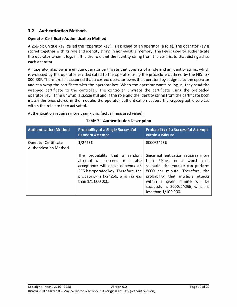
3.2 Authentication Methods
Operator Certificate Authentication Method
A 256-bit unique key, called the “operator key”, is assigned to an operator (a role). The operator key is stored together with its role and identity string in non-volatile memory. The key is used to authenticate the operator when it logs in. It is the role and the identity string from the certificate that distinguishes each operator.
An operator also owns a unique operator certificate that consists of a role and an identity string, which is wrapped by the operator key dedicated to the operator using the procedure outlined by the NIST SP 800-38F. Therefore it is assumed that a correct operator owns the operator key assigned to the operator and can wrap the certificate with the operator key. When the operator wants to log in, they send the wrapped certificate to the controller. The controller unwraps the certificate using the preloaded operator key. If the unwrap is successful and if the role and the identity string from the certificate both match the ones stored in the module, the operator authentication passes. The cryptographic services within the role are then activated.
Authentication requires more than 7.5ms (actual measured value).
Table 7 – Authentication Description
Authentication Method Probability of a Single Successful Random Attempt
Probability of a Successful Attempt within a Minute
Operator Certificate Authentication Method
1/2^256
The probability that a random attempt will succeed or a false acceptance will occur depends on 256-bit operator key. Therefore, the probability is 1/2^256, which is less than 1/1,000,000.
8000/2^256
Since authentication requires more than 7.5ms, in a worst case scenario, the module can perform 8000 per minute. Therefore, the probability that multiple attacks within a given minute will be successful is 8000/2^256, which is less than 1/100,000.
Copyright Hitachi, 2016 - 2020 Version 9.0 Page 14 of 22 Hitachi Public Material – May be reproduced only in its original entirety (without revision).
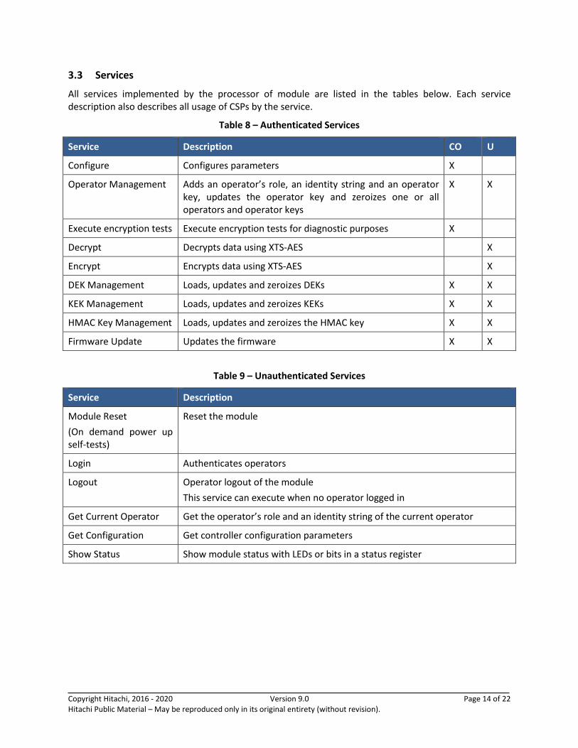
3.3 Services
All services implemented by the processor of module are listed in the tables below. Each service description also describes all usage of CSPs by the service.
Table 8 – Authenticated Services
Service Description CO U
Configure Configures parameters X
Operator Management Adds an operator’s role, an identity string and an operator key, updates the operator key and zeroizes one or all operators and operator keys
X X
Execute encryption tests Execute encryption tests for diagnostic purposes X
Decrypt Decrypts data using XTS-AES X
Encrypt Encrypts data using XTS-AES X
DEK Management Loads, updates and zeroizes DEKs X X
KEK Management Loads, updates and zeroizes KEKs X X
HMAC Key Management Loads, updates and zeroizes the HMAC key X X
Firmware Update Updates the firmware X X
Table 9 – Unauthenticated Services
Service Description
Module Reset
(On demand power up self-tests)
Reset the module
Login Authenticates operators
Logout Operator logout of the module
This service can execute when no operator logged in
Get Current Operator Get the operator’s role and an identity string of the current operator
Get Configuration Get controller configuration parameters
Show Status Show module status with LEDs or bits in a status register

Copyright Hitachi, 2016 - 2020 Version 9.0 Page 15 of 22 Hitachi Public Material – May be reproduced only in its original entirety (without revision).
Table 10 defines the relationship between access to CSPs and the different module services. The modes of access shown in the table are defined as:
• G = Generate: The module generates the CSP.
• R = Read: The module reads the CSP. The read access is typically performed before the module uses the CSP.
• E = Execute: The module executes using the CSP.
• W = Write: The module writes the CSP. The write access is typically performed after a CSP is imported into the module, when the module generates a CSP, or when the module overwrites an existing CSP.
• Z = Zeroize: The module zeroizes the CSP.
Table 10 – CSP Access Rights within Services
Service
CSPs
KEKini KEK DEK Operator Key
HMAC Key
Configure
Operator Management E W/Z
Execute encryption test
Decrypt E
Encrypt E
DEK Management E W/Z
KEK Management E/W/Z E/W/Z
HMAC Key Management E W/Z
Firmware Update E
Module Reset(Self-test)
Login E
Logout E
Get Current Operator
Get Configuration
Show Status
Copyright Hitachi, 2016 - 2020 Version 9.0 Page 16 of 22 Hitachi Public Material – May be reproduced only in its original entirety (without revision).
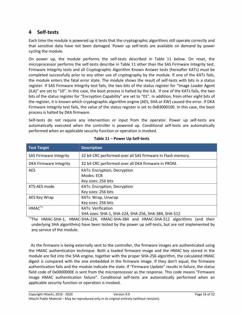
4 Self-tests
Each time the module is powered up it tests that the cryptographic algorithms still operate correctly and that sensitive data have not been damaged. Power up self-tests are available on demand by power cycling the module.
On power up, the module performs the self-tests described in Table 11 below. On reset, the microprocessor performs the self-tests describe in Table 11 other than the SAS Firmware Integrity test. Firmware Integrity tests and all Cryptographic Algorithm Known Answer tests (hereafter KATs) must be completed successfully prior to any other use of cryptography by the module. If one of the KATs fails, the module enters the fatal error state. The module shows the result of self-tests with bits in a status register. If SAS Firmware Integrity test fails, the two bits of the status register for “Image Loader Agent (ILA)” are set to “10”. In this case, the boot process is halted by the ILA. If one of the KATs fails, the two bits of the status register for “Encryption Capability” are set to “01”. In addition, from other eight bits of the register, it is known which cryptographic algorithm engine (AES, SHA or KW) caused the error. If DKA Firmware Integrity test fails, the value of the status register is set to 0x83000100. In this case, the boot process is halted by DKA firmware.
Self-tests do not require any intervention or input from the operator. Power up self-tests are automatically executed when the controller is powered up. Conditional self-tests are automatically performed when an applicable security function or operation is invoked.
Table 11 – Power Up Self-tests
Test Target Description
SAS Firmware Integrity 32 bit CRC performed over all SAS firmware in Flash memory.
DKA Firmware Integrity 32 bit CRC performed over all DKA firmware in PROM.
AES KATs: Encryption, Decryption Modes: ECB Key sizes: 256 bits
XTS-AES mode KATs: Encryption, Decryption Key sizes: 256 bits
AES Key Wrap KATs: Wrap, Unwrap Key sizes: 256 bits
HMAC*1 KATs: Verification SHA sizes: SHA-1, SHA-224, SHA-256, SHA-384, SHA-512
*1The HMAC-SHA-1, HMAC-SHA-224, HMAC-SHA-384 and HMAC-SHA-512 algorithms (and their underlying SHA algorithms) have been tested by the power up self-tests, but are not implemented by any service of the module.
As the firmware is being externally sent to the controller, the firmware images are authenticated using the HMAC authentication technique. Both a loaded firmware image and the HMAC key stored in the module are fed into the SHA engine, together with the proper SHA-256 algorithm, the calculated HMAC digest is compared with the one embedded in the firmware image. If they don't equal, the firmware authentication fails and the module indicate the state. If “Firmware Update” results in failure, the status field code of 0x0000000E is sent from the microprocessor as the response. This code means “Firmware image HMAC authentication failure”. Conditional self-tests are automatically performed when an applicable security function or operation is invoked.
Copyright Hitachi, 2016 - 2020 Version 9.0 Page 17 of 22 Hitachi Public Material – May be reproduced only in its original entirety (without revision).
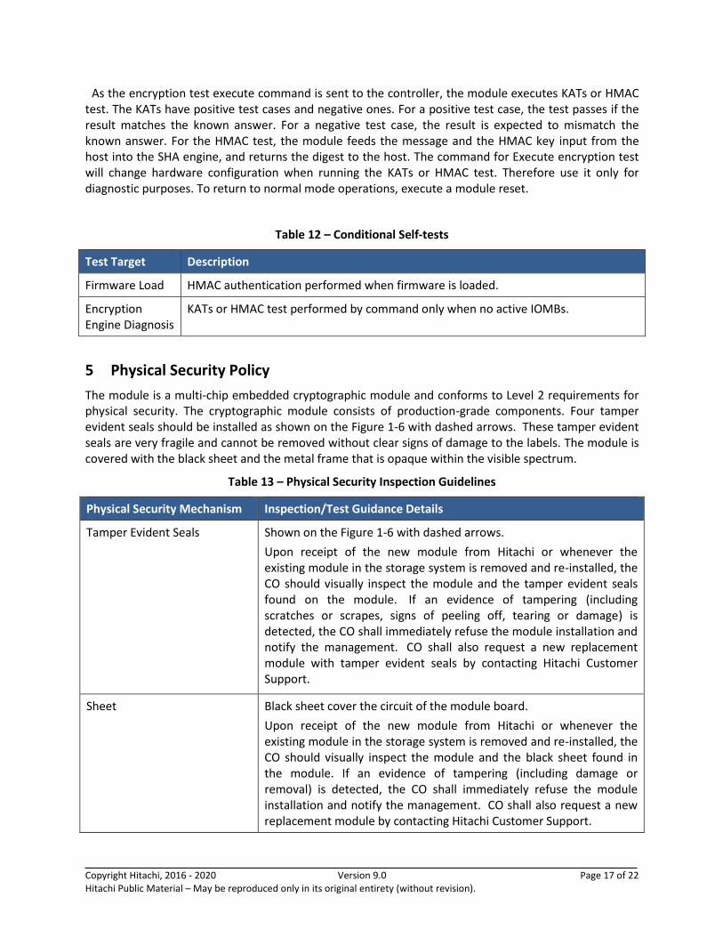
As the encryption test execute command is sent to the controller, the module executes KATs or HMAC test. The KATs have positive test cases and negative ones. For a positive test case, the test passes if the result matches the known answer. For a negative test case, the result is expected to mismatch the known answer. For the HMAC test, the module feeds the message and the HMAC key input from the host into the SHA engine, and returns the digest to the host. The command for Execute encryption test will change hardware configuration when running the KATs or HMAC test. Therefore use it only for diagnostic purposes. To return to normal mode operations, execute a module reset.
Table 12 – Conditional Self-tests
Test Target Description
Firmware Load HMAC authentication performed when firmware is loaded.
Encryption Engine Diagnosis
KATs or HMAC test performed by command only when no active IOMBs.
5 Physical Security Policy
The module is a multi-chip embedded cryptographic module and conforms to Level 2 requirements for physical security. The cryptographic module consists of production-grade components. Four tamper evident seals should be installed as shown on the Figure 1-6 with dashed arrows. These tamper evident seals are very fragile and cannot be removed without clear signs of damage to the labels. The module is covered with the black sheet and the metal frame that is opaque within the visible spectrum.
Table 13 – Physical Security Inspection Guidelines
Physical Security Mechanism Inspection/Test Guidance Details
Tamper Evident Seals Shown on the Figure 1-6 with dashed arrows.
Upon receipt of the new module from Hitachi or whenever the existing module in the storage system is removed and re-installed, the CO should visually inspect the module and the tamper evident seals found on the module. If an evidence of tampering (including scratches or scrapes, signs of peeling off, tearing or damage) is detected, the CO shall immediately refuse the module installation and notify the management. CO shall also request a new replacement module with tamper evident seals by contacting Hitachi Customer Support.
Sheet Black sheet cover the circuit of the module board.
Upon receipt of the new module from Hitachi or whenever the existing module in the storage system is removed and re-installed, the CO should visually inspect the module and the black sheet found in the module. If an evidence of tampering (including damage or removal) is detected, the CO shall immediately refuse the module installation and notify the management. CO shall also request a new replacement module by contacting Hitachi Customer Support.
Copyright Hitachi, 2016 - 2020 Version 9.0 Page 18 of 22 Hitachi Public Material – May be reproduced only in its original entirety (without revision).
6 Operational Environment
The module is designated as a limited operational environment under the FIPS 140-2 definitions. The module includes a firmware load service to support necessary updates. New firmware versions within the scope of this validation must be validated through the FIPS 140-2 CMVP. Any other firmware loaded into this module is out of the scope of this validation and require a separate FIPS 140-2 validation.
7 Mitigation of Other Attacks Policy
The module does not mitigate other attacks.
Copyright Hitachi, 2016 - 2020 Version 9.0 Page 19 of 22 Hitachi Public Material – May be reproduced only in its original entirety (without revision).
8 Security Rules and Guidance
The module design corresponds to the module security rules. This section documents the security rules enforced by the cryptographic module to implement the security requirements of this FIPS 140-2 Level 2 module.
1. The module shall provide two distinct operator roles: User and Cryptographic Officer.
2. The module shall provide role-based authentication.
3. The module shall clear previous authentications on power cycle.
4. When the module has not been placed in a valid role, the operator shall not have access to any cryptographic services.
5. The operator shall be capable of commanding the module to perform the power up self-tests by cycling power or resetting the module.
6. Power up self-tests do not require any operator action.
7. Data output shall be inhibited during self-tests, zeroization, and error states.
8. Status information does not contain CSPs or sensitive data that if misused could lead to a compromise of the module.
9. There are no restrictions on which keys or CSPs are zeroized by the zeroization service.
10. The module does not support a maintenance interface or role.
11. The module does not support manual key entry.
12. The module does not have any external input/output devices used for entry/output of data.
13. The module does not enter or output plaintext CSPs.
14. The module does not support the update of the logical serial number or vendor ID.
8.1 Crypto Officer Guidance
The Crypto Officer must configure and enforce the following initialization procedures in order to operate in FIPS approved mode of operation:
1. Verify that the name and part number of module is eSCAS(WP820) or eSCAM(WP820) and
version is B/A5, B/A6, B/A7, B/A8, B/A9 or B/A10 and the tamper evident seals are installed to
specified position.
2. Verify that the DKA firmware version of module is 00F3F003 and the SAS firmware version of
module is 02.09.28.00, 02.09.32.00 or 02.09.37.00.
3. Enable the encryption feature.
4. Configure encryption environmental settings.
When the step mentioned above is completed, one KEK and two Operator Keys have been input into the module.
Copyright Hitachi, 2016 - 2020 Version 9.0 Page 20 of 22 Hitachi Public Material – May be reproduced only in its original entirety (without revision).
See [User Guide] Chapter 2 for detail of initialization procedures.
Otherwise, no specific commands or settings are required to place the module in FIPS-approved mode of operation.
8.2 User Guidance
The User must configure and enforce the following initialization procedures in order to operate in FIPS approved mode of operation:
1. Enable data encryption on the parity group.
2. Format the Volumes at the parity-group level.
See [User Guide] Chapter 4 for detail of initialization procedures.
Copyright Hitachi, 2016 - 2020 Version 9.0 Page 21 of 22 Hitachi Public Material – May be reproduced only in its original entirety (without revision).
9 Design Assurance Policy
9.1 Configuration Management Overview
Programs and documents are managed using a proprietary web-base configuration management system (Electric Stock System). Documents for validation and hardware components are managed by revision management by a proprietary ledger.
9.2 Installation, Initialization, and start-up Overview
The procedure is described in section 8.1.
9.3 Secure Delivery and Operation Overview
The module shipped to customers from the factory or the distribution centers. The module is delivered by the contracted carrier and unpacked by the contacted service personnel on site, and its contents are confirmed by the personnel.
Copyright Hitachi, 2016 - 2020 Version 9.0 Page 22 of 22 Hitachi Public Material – May be reproduced only in its original entirety (without revision).
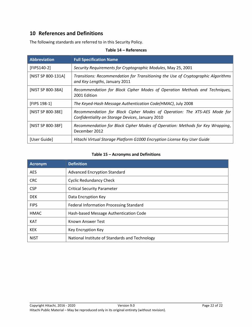
10 References and Definitions
The following standards are referred to in this Security Policy.
Table 14 – References
Abbreviation Full Specification Name
[FIPS140-2] Security Requirements for Cryptographic Modules, May 25, 2001
[NIST SP 800-131A] Transitions: Recommendation for Transitioning the Use of Cryptographic Algorithms and Key Lengths, January 2011
[NIST SP 800-38A] Recommendation for Block Cipher Modes of Operation Methods and Techniques, 2001 Edition
[FIPS 198-1] The Keyed-Hash Message Authentication Code(HMAC), July 2008
[NIST SP 800-38E] Recommendation for Block Cipher Modes of Operation: The XTS-AES Mode for Confidentiality on Storage Devices, January 2010
[NIST SP 800-38F] Recommendation for Block Cipher Modes of Operation: Methods for Key Wrapping, December 2012
[User Guide] Hitachi Virtual Storage Platform G1000 Encryption License Key User Guide
Table 15 – Acronyms and Definitions
Acronym Definition
AES Advanced Encryption Standard
CRC Cyclic Redundancy Check
CSP Critical Security Parameter
DEK Data Encryption Key
FIPS Federal Information Processing Standard
HMAC Hash-based Message Authentication Code
KAT Known Answer Test
KEK Key Encryption Key
NIST National Institute of Standards and Technology