Embed Size (px)
DESCRIPTION
Hitachi Hnas imp doc
Citation preview
MK-92HNAS015-05
Hitachi NAS Platform and Hitachi Unified StorageFile Module System Installation Guide
Release 12.0

ii Hitachi NAS Platform and Hitachi Unified Storage
© 2011-2014 Hitachi, Ltd. All rights reserved.
No part of this publication may be reproduced or transmitted in any form or by any means, electronic or mechanical, including photocopying and recording, or stored in a database or retrieval system for any purpose without the express written permission of Hitachi, Ltd.
Hitachi, Ltd., reserves the right to make changes to this document at any time without notice and assumes no responsibility for its use. This document contains the most current information available at the time of publication. When new or revised information becomes available, this entire document will be updated and distributed to all registered users.
Some of the features described in this document might not be currently available. Refer to the most recent product announcement for information about feature and product availability, or contact Hitachi Data Systems Corporation at https://portal.hds.com.
Notice: Hitachi, Ltd., products and services can be ordered only under the terms and conditions of the applicable Hitachi Data Systems Corporation agreements. The use of Hitachi, Ltd., products is governed by the terms of your agreements with Hitachi Data Systems Corporation.
Hitachi is a registered trademark of Hitachi, Ltd., in the United States and other countries. Hitachi Data Systems is a registered trademark and service mark of Hitachi, Ltd., in the United States and other countries.
Archivas, Dynamic Provisioning, Essential NAS Platform, HiCommand, Hi-Track, ShadowImage, Tagmaserve, Tagmasoft, Tagmasolve, Tagmastore, TrueCopy, Universal Star Network, and Universal Storage Platform are registered trademarks of Hitachi Data Systems Corporation.
AIX, AS/400, DB2, Domino, DS8000, Enterprise Storage Server, ESCON, FICON, FlashCopy, IBM, Lotus, OS/390, RS6000, S/390, System z9, System z10, Tivoli, VM/ESA, z/OS, z9, zSeries, z/VM, z/VSE are registered trademarks and DS6000, MVS, and z10 are trademarks of International Business Machines Corporation.
All other trademarks, service marks, and company names in this document or website are properties of their respective owners.
Microsoft product screen shots are reprinted with permission from Microsoft Corporation.
System Installation Guide iii
Notice
Hitachi Data Systems products and services can be ordered only under the terms and conditions of Hitachi Data Systems’ applicable agreements. The use of Hitachi Data Systems products is governed by the terms of your agreements with Hitachi Data Systems.
This product includes software developed by the OpenSSL Project for use in the OpenSSL Toolkit (http://www.openssl.org/). Some parts of ADC use open source code from Network Appliance, Inc. and Traakan, Inc.
Part of the software embedded in this product is gSOAP software. Portions created by gSOAP are copyright 2001-2009 Robert A. Van Engelen, Genivia Inc. All rights reserved. The software in this product was in part provided by Genivia Inc. and any express or implied warranties, including, but not limited to, the implied warranties of merchantability and fitness for a particular purpose are disclaimed. In no event shall the author be liable for any direct, indirect, incidental, special, exemplary, or consequential damages (including, but not limited to, procurement of substitute goods or services; loss of use, data, or profits; or business interruption) however caused and on any theory of liability, whether in contract, strict liability, or tort (including negligence or otherwise) arising in any way out of the use of this software, even if advised of the possibility of such damage.
The product described in this guide may be protected by one or more U.S. patents, foreign patents, or pending applications.
Notice of Export Controls
Export of technical data contained in this document may require an export license from the United States government and/or the government of Japan. Contact the Hitachi Data Systems Legal Department for any export compliance questions.
iv Hitachi NAS Platform and Hitachi Unified Storage
Document Revision Level
Contact
Hitachi Data Systems2845 Lafayette StreetSanta Clara, California 95050-2627https://portal.hds.com
North America: 1-800-446-0744
Revision Date Description
MK-92HNAS015-00 November 2012 First publication
MK-92HNAS015-01 July 2013 Revision 1, replaces and supersedesMK-92HNAS015-00
MK-92HNAS015-02 August 2013 Revision 2, replaces and supersedesMK-92HNAS015-01
MK-92HNAS015-03 September 2013 Revision 3, replaces and supersedesMK-92HNAS015-02
MK-92HNAS015-04 November 2013 Revision 4, replaces and supersedesMK-92HNAS015-03
MK-92HNAS015-05 June 2014 Revision 5, replaces and supersedesMK-92HNAS015-04
Contents
Chapter 1: About this document ................................................................9Applicable products ..........................................................................................................................10Target configurations ........................................................................................................................10Target audience ................................................................................................................................10Related documentation .....................................................................................................................10Training offerings .............................................................................................................................11
Chapter 2: System requirements ..............................................................13General specifications ......................................................................................................................14Browser support ................................................................................................................................14
Java requirements .................................................................................................................14License key overview .......................................................................................................................14
Chapter 3: Configuring the logical layer .................................................17Preparing for system configuration ..................................................................................................18Configuring the storage system ........................................................................................................19
Connecting the storage controller .........................................................................................19Configuring the storage in the storage GUI .........................................................................21Configuring the storage in the SNM2 software ....................................................................25Installing the license keys .....................................................................................................27Adding the storage arrays .....................................................................................................29Adding the spare drives ........................................................................................................31Creating the RAID groups ....................................................................................................32Creating the storage volumes ...............................................................................................34Configuring the host groups .................................................................................................36Configuring additional storage settings based on firmware .................................................39
Setting up the OS and software on an SMU .....................................................................................44Configuring a server administrative IP to access embedded SMUs .....................................44Installing the CentOS operating system ...............................................................................45Initially configuring an external SMU .................................................................................47Installing and configuring the SMU software ......................................................................47
Configuring an HNAS Platform or HUS File Module server ..........................................................50Configuring the first HNAS or HUS File Module server .....................................................50Configuring the second HNAS or HUS File Module server ................................................54Adding the servers as managed servers in the SMU ............................................................57Building a two-node cluster ..................................................................................................57
Zoning and configuring the Fibre Channel switch ...........................................................................60Configuring the Ethernet switch .......................................................................................................63
Configuring the Ethernet switch initial setup .......................................................................64Configuring the Ethernet switch to the storage system .......................................................66Configuring HyperTerminal for the Ethernet switch configuration .....................................66Recovering from a lost password during switch configuration ............................................67
Configuring a system with an embedded SMU ................................................................................67Customizing the server administrative IP address ................................................................67Using the server setup wizard ...............................................................................................68
Configuring a system with an external SMU ...................................................................................74Initially configuring an external SMU .................................................................................74
| TOC | 5
Selecting external SMU-managed servers ............................................................................74Using the server setup wizard with a single-node configuration ..........................................75
Backing up configuration files .........................................................................................................81Backing up the server registry ..............................................................................................82Backing up the external SMU configuration ........................................................................82Backing up the RAID controller configuration ....................................................................82
Chapter 4: Accepting your system ...........................................................83Checkpoint ........................................................................................................................................84Additional system verification tests .................................................................................................85
Verifying the SD superflush settings ....................................................................................85Verifying and configuring FC switches ...............................................................................85
Appendix A: Upgrading storage firmware ..............................................87Upgrading storage array firmware ....................................................................................................88
Appendix B: Configuring superflush settings .........................................91Configuring the superflush settings ..................................................................................................92
Appendix C: Upgrading HNAS or HUS File Module server software.....................................................................................................................93
Upgrading operating systems ...........................................................................................................94Upgrading the server software ..............................................................................................94
Upgrading server firmware ...............................................................................................................94Upgrading firmware on servers not usually managed by the SMU .....................................94
Appendix D: Running the NAS-PRECONFIG script ............................97Running the NAS-PRECONFIG script ............................................................................................98
Appendix E: Using a virtual SMU ...........................................................99Using a virtual SMU .......................................................................................................................100Installation requirements ................................................................................................................100Installing SMU software in a VM ..................................................................................................101Upgrading the OS for a virtual SMU .............................................................................................102Configuring vSwitches ...................................................................................................................103Deploying CentOS SMU VMs .......................................................................................................103Installing SMU software in a VM ..................................................................................................104Configuring VM resource allocations ............................................................................................105Installing VMware tools .................................................................................................................106
Appendix F: Upgrading an external SMU ............................................107About upgrading an external SMU .................................................................................................108Upgrading the SMU OS .................................................................................................................108Upgrading the SMU software .........................................................................................................109
Appendix G: Running the SMU-CONFIG script .................................111Running the SMU-CONFIG script .................................................................................................112
6 | | TOC

Appendix H: Adding nodes to an N-way cluster (three-plus nodes) ...115Maximum number of nodes supported ...........................................................................................116Adding nodes to an N-way cluster .................................................................................................116Cluster cable configurations ...........................................................................................................117
| TOC | 7

8 | | TOC
Chapter
1About this document
Topics:
• Applicable products• Target configurations• Target audience• Related documentation• Training offerings
This manual guides you through the installation process, one phase at a time,with checkpoints at the end of each phase to minimize potential delays.
Important Documentation Note: Check for the most current version of theSystem Installation Guide on TISC. TISC is an HDS-internal site and is onlyavailable for HDS personnel.
The installation process includes the following phases:
• Systems Assurance
Before arriving onsite, the systems assurance phase should have beencompleted, which includes capturing the architecture and designexpectations related to the installation and the related site surveyinformation. This must be performed in advanced to ensure an appropriatesolution is architected for the customer’s needs. Results of the systemsassurance is shipped with the system in the enclosed documentationwallet.
• Preinstallation Verification
During this phase, the shipment is confirmed, and an installation date andduration should be agreed on. The systems assurances and environmentalrequirements will be reviewed one final time to ensure a smoothinstallation is accomplished.
• Physical Layer Installation
During this phase, all system components are unpacked, racked, andcabled according to the preestablished design. At the end of this phase, thesystem undergoes a power-on check to ensure all the hardware and relatedcomponents are healthy.
• Logical Layer Installation
Most of this phase is designed to be completed by the customer, as itinvolves the use of configuration wizards to enter various customer,infrastructure, and network service information. During this phase, a basicsystem is automatically configured with a storage pool, file system, and asingle share and export. This allows for the connection of clients to thesystem to verify it is complete and healthfully operating.
• Service Acceptance
The final phase is used to establish a connection to Hitachi Data SystemsSupport Center, verify the Call-Home information is received by theHitachi Data Systems Support Center database automatically, andestablish service entitlement to confirm support levels and support portalaccess.
Applicable productsApplicable products include:
See the documentation in the following table for information about the Hitachi Unified Storage (HUS), HUS VM, andHUS VSP products:
Document number Document title
MK-91DF8303-07 Hitachi Unified Storage Getting Started Guide
MK-92HM7003-03 Hitachi Unified Storage VM Getting Started Guide
MK-92HNAS026-00 Hitachi Unified Storage VM Best Practices Guide for HNAS Solutions
MK-92HNAS025-00 Hitachi USP-V/VSP Best Practice Guide for HNAS Solutions
Target configurationsConfigurations include:
• Single server systems with storage (SAN or direct-attached)• Clustered systems with up to two nodes with storage (SAN or direct-attached)• Cluster (two or more nodes in a cluster, up to the supported maximum number of nodes, with an attached SAN)• System management unit (SMU) as required by the customer site for the above configurations• Optional standby SMU, if required by the customer configuration
Note: A server is called a node in clustered configurations.
Target audienceBefore attempting to install a Hitachi NAS Platform system and storage arrays, the following are required:
• Training with the Hitachi NAS Platform server and storage arrays, and their installation procedures.• Basic Microsoft Windows and UNIX administration skills.
Related documentation
System Access Guide (MK-92HNAS014) (MK-92USF002): In PDF format, this guide explains how to log in to thesystem, provides information about accessing the NAS server/cluster CLI and the SMU CLI, and providesinformation about the documentation, help, and search capabilities available in the system.
Server and Cluster Administration Guide (MK-92HNAS010) (MK-92USF007): In PDF format, this guide providesinformation about administering servers, clusters, and server farms. Includes information about licensing, namespaces, upgrading firmware, monitoring servers and clusters, the backing up and restoring configurations.
Storage System User Administration Guide (MK-92HNAS013) (MK-92USF011): In PDF format, this guide explainsuser management, including the different types of system administrator, their roles, and how to create and managethese users.
Network Administration Guide (MK-92HNAS008) (MK-92USF003): In PDF format, this guide provides informationabout the server's network usage, and explains how to configure network interfaces, IP addressing, name anddirectory services.
10 | | About this document
File Services Administration Guide (MK-92HNAS006) (MK-92USF004): In PDF format, this guide explains aboutfile system formats, and provides information about creating and managing file systems, and enabling and configuringfile services (file service protocols).
Data Migrator Administration Guide (MK-92HNAS005) (MK-92USF005): In PDF format, this guide providesinformation about the Data Migrator feature, including how to set up migration policies and schedules.
Storage Subsystem Administration Guide (MK-92HNAS012) (MK-92USF006): In PDF format, this guide providesinformation about managing the supported storage subsystems (RAID arrays) attached to the server/cluster. Includesinformation about tiered storage, storage pools, system drives (SDs), SD groups, and other storage device relatedconfiguration and management features and functions.
Snapshot Administration Guide (MK-92HNAS011) (MK-92USF008): In PDF format, this guide provides informationabout configuring the server to take and manage snapshots.
Replication and Disaster Recovery Administration Guide (MK-92HNAS009) (MK-92USF009): In PDF format, thisguide provides information about replicating data using file-based replication and object-based replication, providesinformation on setting up replication policies and schedules, and using replication features for disaster recoverypurposes.
Antivirus Administration Guide (MK-92HNAS004) (MK-92USF010): In PDF format, this guide describes thesupported antivirus engines, provides information about how to enable them, and how to configure the system to usethem.
Backup Administration Guide (MK-92HNAS007) (MK-92USF012): In PDF format, this guide provides informationabout configuring the server to work with NDMP, and making and managing NDMP backups. Also includesinformation about Hitachi NAS Synchronous Image Backup.
Command Line Reference: Describes how to administer the system by entering commands at a command prompt.
Hitachi NAS Platform 3080 and 3090 G1 Hardware Reference(MK-92HNAS016): In PDF format, this guideprovides an overview of the first-generation server hardware, describes how to resolve any problems, and replacepotentially faulty parts.
Hitachi NAS Platform 3080 and 3090 G2 and Hitachi Unified Storage File Module Hardware Reference(MK-92HNAS017) (MK-92USF001): In PDF format, this guide provides an overview of the second-generationserver hardware, describes how to resolve any problems, and replace potentially faulty parts.
Hitachi NAS Platform and Hitachi Unified Storage File Module Series 4000 Hardware Reference (MK-92HNAS030)MK-92HNAS030): In PDF format, this guide provides an overview of the HNAS Series 4000 and Hitachi UnifiedStorage File Module server hardware, describes how to resolve any problems, and how to replace potentially faultycomponents.
Release notes: Provides the most up-to-date information about the system, including new feature summaries, upgradeinstructions, and fixed and known defects.
Note: For a complete list of Hitachi NAS open source software copyrights and licenses, see the System AccessGuide.
Training offeringsHitachi Data Systems offers formalized training to authorized partners and customers. Please contact your HitachiData Systems representative for more information, as it is required before attempting any system installation orrepairs.
| About this document | 11

Chapter
2System requirements
Topics:
• General specifications• Browser support• License key overview
Confirm the system meets the minimum requirements to efficiently use thesystem and take advantage of its features.
General specificationsHitachi Data Systems provides support for a final quote and configuration review. Key account information andsolution attributes will be recorded, and the overall delivery objectives, goals, and prerequisites will be discussed.
Because the type and number of components might differ for each system and storage server, refer to thedocumentation wallet provided with the system to ensure its requirements are met before any hardware componentsarrive onsite. Contact Hitachi Data Systems Support Center immediately if you have any questions or concerns.
See the Hitachi NAS Platform Series 4000Hardware Reference and the specifications provided for the 4000 seriessystem for more information.
See the Hitachi NAS Platform 3080 and 3090 G2 Hardware Reference and the specifications provided for the HNAS3080 and HNAS 3090 servers for more information.
Browser supportUse one of the following browsers to run Web Manager, the system management unit (SMU) web-based graphicaluser interface (GUI):
• Microsoft Internet Explorer: version 8.0 or later.• Mozilla Firefox: version 6.0 or later.
Note: The SMU uses cookies and sessions to remember user selections on various pages. Therefore, open onlyone web browser window or tab to the SMU per workstation or computer. If multiple tabs or windows areopened from the same workstation or computer, any changes made in one tab or window might unexpectedlyaffect the other tabs or windows.
Java requirementsThe following Java Runtime Environment is required to enable some advanced Web Manager functionality:
• Oracle Java Runtime Environment, version 1.6
License key overviewServers are provided with the software already installed. You add the licenses for the services you want. When youreplace a server, you need to manually order a replacement set of licenses. This is a two stage process, where you firstobtain a set of emergency license keys to get the system up and running, and then obtain a permanent set of keys.
• Licensed services (keyed)
License keys are required to add services to servers and can be purchased and added as required by the customer.A License Certificate identifies all of the purchased services and should be kept in a safe place. The UserDocumentation Wallet that was shipped with the system includes the License Certificate. Licensed softwarepackages are described in Building a two-node cluster on page 57.
• Obtaining customer license keys
License keys are included in the normal Insight order process. If you encounter problems with the key process,please email: mailto://[email protected]
• Permanent key
The permanent key is obtained through a specialized process requiring both customer and system information.Typically the information will include the customer number, serial number of the storage system, and the featureto be activated.
14 | | System requirements

Note: Permanent license keys for a replacement server are normally provided within seven days.
• Temporary key
For customers who want to test a particular feature, a temporary key is available. The temporary key enablessoftware features for a specified period of time (60 days), after which the function is disabled. During or after thetrial period, the customer may elect to purchase a permanent key. A 60-day All Suite temporary key can beordered in Insight. However, [email protected] can assist for keys required outside of the Insight ordering process.
• Emergency key
Emergency key generation tools for all current NAS File OS versions are kept in each contact center. Foremergency situations, an emergency key can be obtained from the GCC for your geography. Emergency keys willremain functional for 14 days from the creation date. Emergency keys must be replaced with a permanent key.
Note: See the System Access Guide for a complete list of End Licensing Agreements.
| System requirements | 15

Chapter
3Configuring the logical layer
Topics:
• Preparing for system configuration• Configuring the storage system• Setting up the OS and software on
an SMU• Configuring an HNAS Platform or
HUS File Module server• Zoning and configuring the Fibre
Channel switch• Configuring the Ethernet switch• Configuring a system with an
embedded SMU• Configuring a system with an
external SMU• Backing up configuration files
The logical layer involves the software configuration for the systemcomponents. This installation phase includes the initial system configuration.After entering the commands from the CLI to set the IP addresses, run theconfiguration wizard to enter in all the relevant systems administration, site-specific, and customer information.
Preparing for system configurationTo expedite the configuration of the system, consider the recommendations in this section.
The administration tool, called the Web Manager, is the graphical user interface (GUI) for the system managementunit (SMU). This GUI provides a browser-based interface for managing standalone or clustered servers and theirattached storage subsystems. This tool allows you to perform most administrative tasks from any client on thenetwork using a supported web browser.
When configuring the storage, you sometimes also use the Hitachi Storage Navigator 2 (SNM2) software. Install theSNM2 software on the computer or laptop that will be used for making the configuration settings. The use of SNM2software is called out when appropriate.
To successfully complete the configuration of the server, you will need the following:
Setting Current configuration
Admin EVS public IP for Eth0
File serving IP address
DNS server IP, primary and secondary
WINS, if any
NIS, if any
NTP server
SMTP server
Cluster name
EVS1 and EVS2 names
EVS1 and EVS2 IP addresses
VLANs for management and data
Your server typically ships with the following pre-configuration:
• Default IP addresses for the system• Any purchased licenses• Depending on the type of storage, system drives (SDs) are created and allowed access
Setting Default/Example
Server root password nasadmin
Server manager password nasadmin
Server admin password nasadmin
Server admin EVS private IP address (Eth1) 192.0.2.2
Server admin EVS public IP address (Eth0) 192.168.31.101
SMU root password nasadmin
SMU Eth0 IP
SMU Eth0 subnet mask
SMU Eth0 gateway
18 | | Configuring the logical layer
Setting Default/Example
SMU domain name
SMU host name
Note: Before connecting the server to your network, ensure that these IP addresses do not conflict with anexisting network.
Configuring the storage systemYou can configure the storage system with the RAID+VOL set up. The storage system software is set up in theStorage Navigator Modular software graphical user interface (GUI).
To set up the storage system, you need to have available the customer information for the RAID+VOL setup. If thisinformation is unavailable, create test RAID groups with at least one volume in each raid group of 20 GB for testingpurposes.
Note: You must use all drives in a test RAID group.
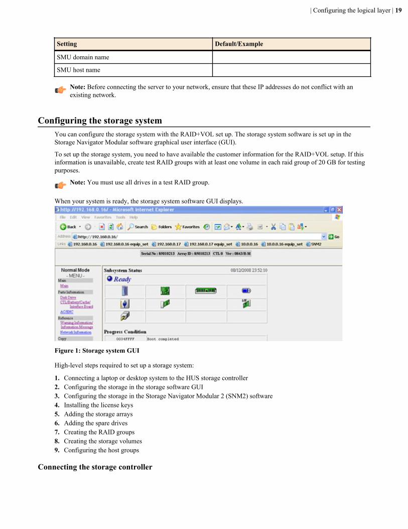
When your system is ready, the storage system software GUI displays.
Figure 1: Storage system GUI
High-level steps required to set up a storage system:
1. Connecting a laptop or desktop system to the HUS storage controller2. Configuring the storage in the storage software GUI3. Configuring the storage in the Storage Navigator Modular 2 (SNM2) software4. Installing the license keys5. Adding the storage arrays6. Adding the spare drives7. Creating the RAID groups8. Creating the storage volumes9. Configuring the host groups
Connecting the storage controller
| Configuring the logical layer | 19
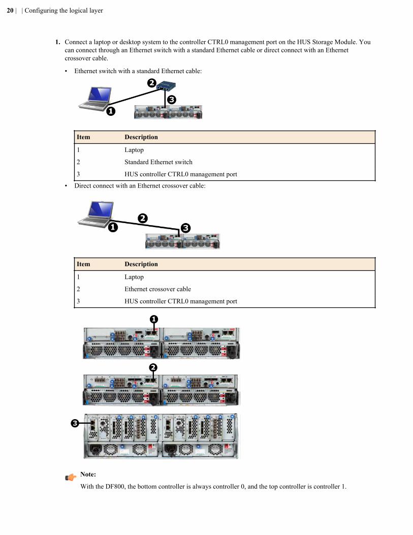
1. Connect a laptop or desktop system to the controller CTRL0 management port on the HUS Storage Module. Youcan connect through an Ethernet switch with a standard Ethernet cable or direct connect with an Ethernetcrossover cable.
• Ethernet switch with a standard Ethernet cable:
Item Description
1 Laptop
2 Standard Ethernet switch
3 HUS controller CTRL0 management port
• Direct connect with an Ethernet crossover cable:
Item Description
1 Laptop
2 Ethernet crossover cable
3 HUS controller CTRL0 management port
Note:
With the DF800, the bottom controller is always controller 0, and the top controller is controller 1.
20 | | Configuring the logical layer
With the DF850, the left controller (seen from the back) is controller 0 and the right is controller 1.
Figure 2: HUS Storage Module models controller CTRL0 management ports
Item Description
1 HUS 110 controller CTRL0 management port
2 HUS 130 controller CTRL0 management port
3 HUS 150 controller CTRL0 management port
2. Configure the IP address of the management station (laptop) with the following settings:
• IP address: 10.0.0.100• Netmask: 255.255.255.0
3. Switch on the storage system.4. Reset the system by pressing first the reset (RST) switch of controller 0 until the orange LED flashes, and then the
reset switch of controller 1.These must be pressed within 5-10 seconds after each other.The network connection will drop as the system is reset into maintenance mode.
After you have made the connections to the storage controller, you can make configuration settings in the storagesystem graphical user interface (GUI).
Configuring the storage in the storage GUIThis section describes how to configure the storage in the graphical user interface (GUI).
1. Open Internet Explorer and access the storage system using http://10.0.0.16The 10.0.0.x address is only accessible if you connect the LAN cable to the maintenance port.
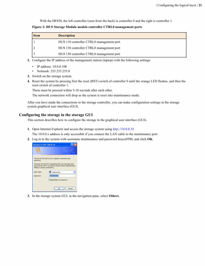
2. Log in to the system with username maintenance and password hosyu9500, and click OK.
3. In the storage system GUI, in the navigation pane, select Others.
| Configuring the logical layer | 21
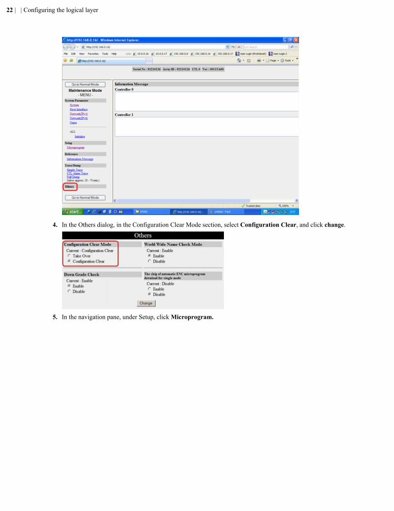
4. In the Others dialog, in the Configuration Clear Mode section, select Configuration Clear, and click change.
5. In the navigation pane, under Setup, click Microprogram.
22 | | Configuring the logical layer
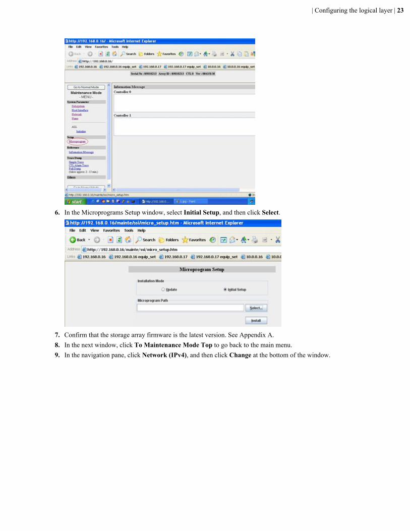
6. In the Microprograms Setup window, select Initial Setup, and then click Select.
7. Confirm that the storage array firmware is the latest version. See Appendix A.8. In the next window, click To Maintenance Mode Top to go back to the main menu.9. In the navigation pane, click Network (IPv4), and then click Change at the bottom of the window.
| Configuring the logical layer | 23
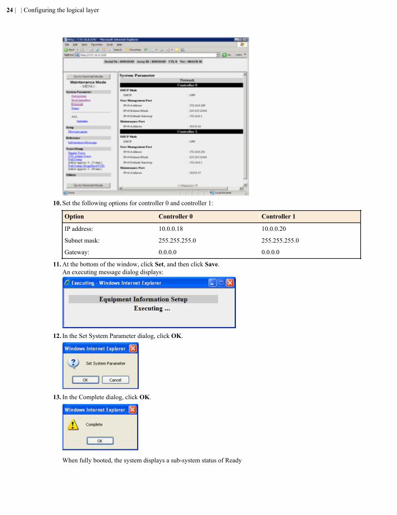
10. Set the following options for controller 0 and controller 1:
Option Controller 0 Controller 1
IP address: 10.0.0.18 10.0.0.20
Subnet mask: 255.255.255.0 255.255.255.0
Gateway: 0.0.0.0 0.0.0.0
11. At the bottom of the window, click Set, and then click Save.An executing message dialog displays:
12. In the Set System Parameter dialog, click OK.
13. In the Complete dialog, click OK.
When fully booted, the system displays a sub-system status of Ready
24 | | Configuring the logical layer
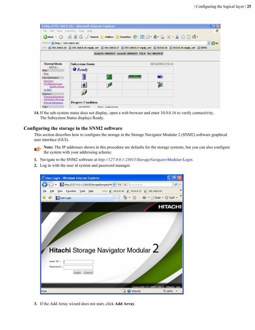
14. If the sub-system status does not display, open a web browser and enter 10.0.0.16 to verify connectivity.The Subsystem Status displays Ready.
Configuring the storage in the SNM2 softwareThis section describes how to configure the storage in the Storage Navigator Modular 2 (SNM2) software graphicaluser interface (GUI).
Note: The IP addresses shown in this procedure are defaults for the storage systems, but you can also configurethe system with your addressing scheme.
1. Navigate to the SNM2 software at http://127.0.0.1:23015/StorageNavigatorModular/Login.2. Log in with the user id system and password manager.
3. If the Add Array wizard does not start, click Add Array.
| Configuring the logical layer | 25
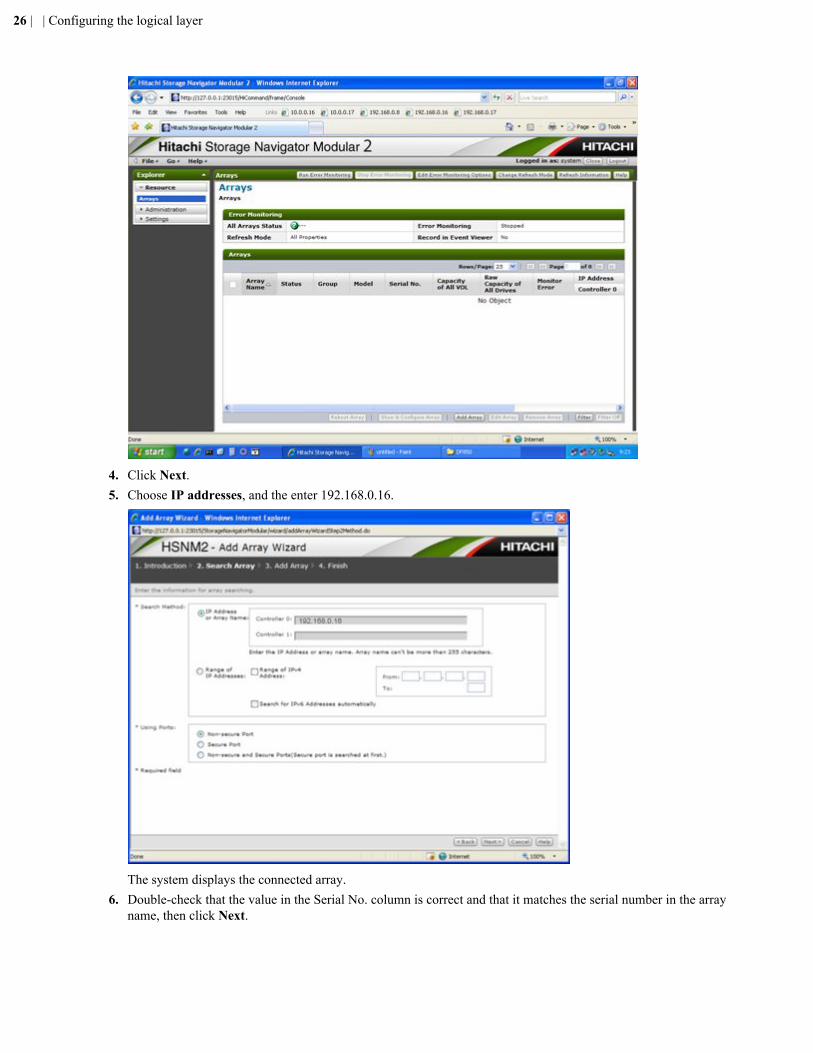
4. Click Next.5. Choose IP addresses, and the enter 192.168.0.16.
The system displays the connected array.6. Double-check that the value in the Serial No. column is correct and that it matches the serial number in the array
name, then click Next.
26 | | Configuring the logical layer
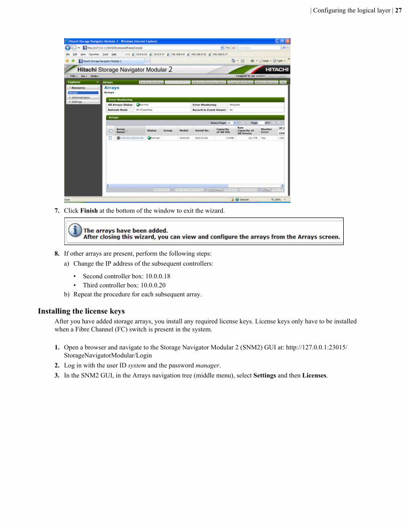
7. Click Finish at the bottom of the window to exit the wizard.
8. If other arrays are present, perform the following steps:a) Change the IP address of the subsequent controllers:
• Second controller box: 10.0.0.18• Third controller box: 10.0.0.20
b) Repeat the procedure for each subsequent array.
Installing the license keysAfter you have added storage arrays, you install any required license keys. License keys only have to be installedwhen a Fibre Channel (FC) switch is present in the system.
1. Open a browser and navigate to the Storage Navigator Modular 2 (SNM2) GUI at: http://127.0.0.1:23015/StorageNavigatorModular/Login
2. Log in with the user ID system and the password manager.3. In the SNM2 GUI, in the Arrays navigation tree (middle menu), select Settings and then Licenses.
| Configuring the logical layer | 27
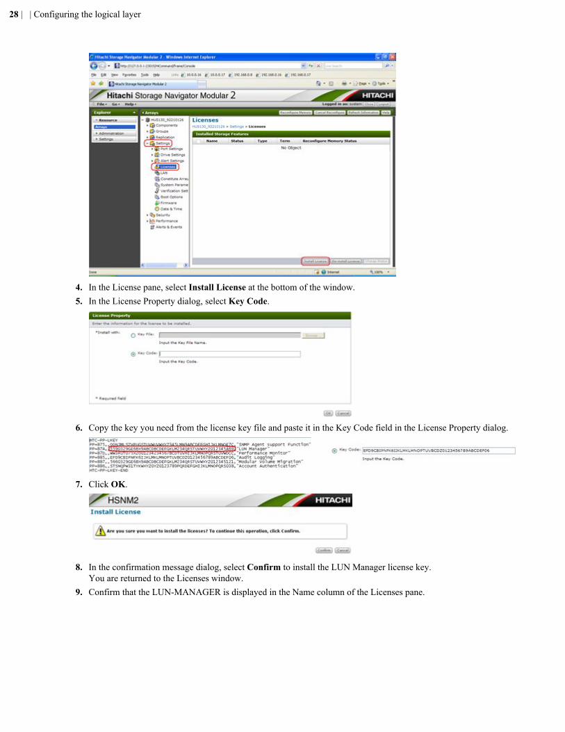
4. In the License pane, select Install License at the bottom of the window.5. In the License Property dialog, select Key Code.
6. Copy the key you need from the license key file and paste it in the Key Code field in the License Property dialog.
7. Click OK.
8. In the confirmation message dialog, select Confirm to install the LUN Manager license key.You are returned to the Licenses window.
9. Confirm that the LUN-MANAGER is displayed in the Name column of the Licenses pane.
28 | | Configuring the logical layer
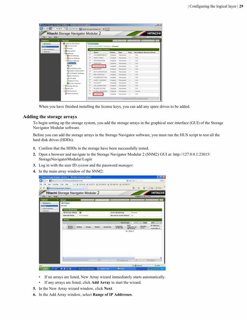
When you have finished installing the license keys, you can add any spare drives to be added.
Adding the storage arraysTo begin setting up the storage system, you add the storage arrays in the graphical user interface (GUI) of the StorageNavigator Modular software.
Before you can add the storage arrays in the Storage Navigator software, you must run the HUS script to test all thehard disk drives (HDDs).
1. Confirm that the HDDs in the storage have been successfully tested.2. Open a browser and navigate to the Storage Navigator Modular 2 (SNM2) GUI at: http://127.0.0.1:23015/
StorageNavigatorModular/Login3. Log in with the user ID system and the password manager.4. In the main array window of the SNM2:
• If no arrays are listed, New Array wizard immediately starts automatically.• If any arrays are listed, click Add Array to start the wizard.
5. In the New Array wizard window, click Next.6. In the Add Array window, select Range of IP Addresses.
| Configuring the logical layer | 29
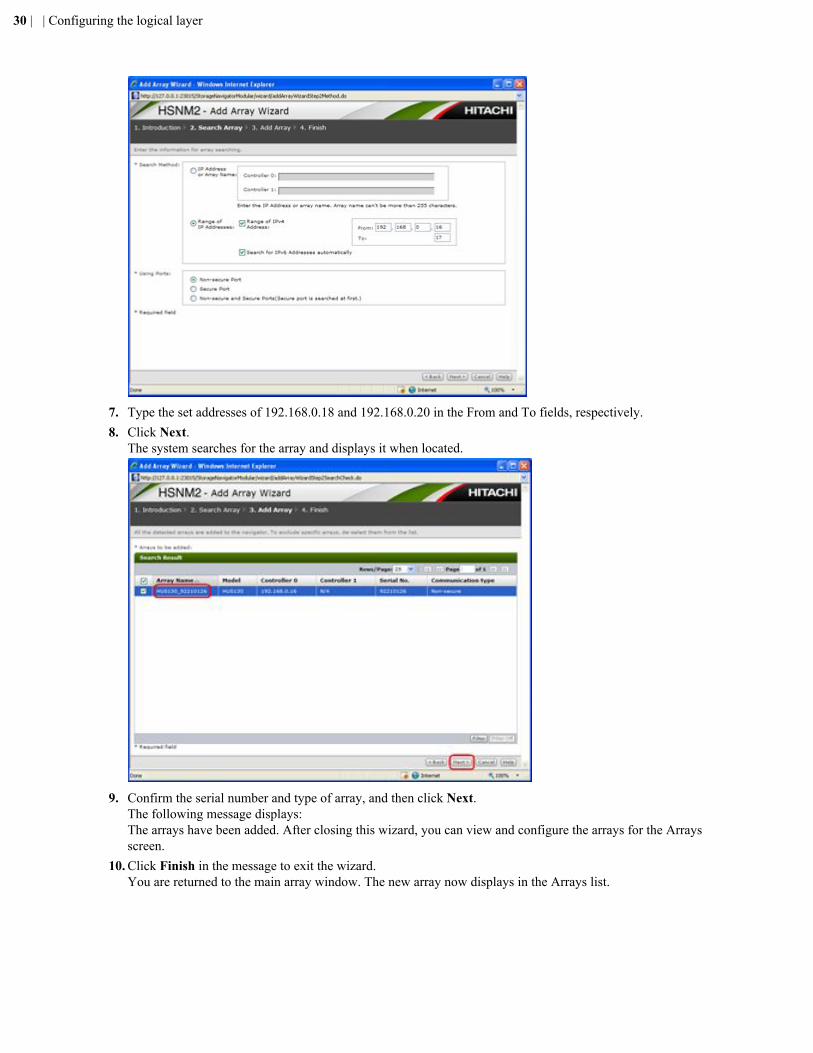
7. Type the set addresses of 192.168.0.18 and 192.168.0.20 in the From and To fields, respectively.8. Click Next.
The system searches for the array and displays it when located.
9. Confirm the serial number and type of array, and then click Next.The following message displays:The arrays have been added. After closing this wizard, you can view and configure the arrays for the Arraysscreen.
10. Click Finish in the message to exit the wizard.You are returned to the main array window. The new array now displays in the Arrays list.
30 | | Configuring the logical layer
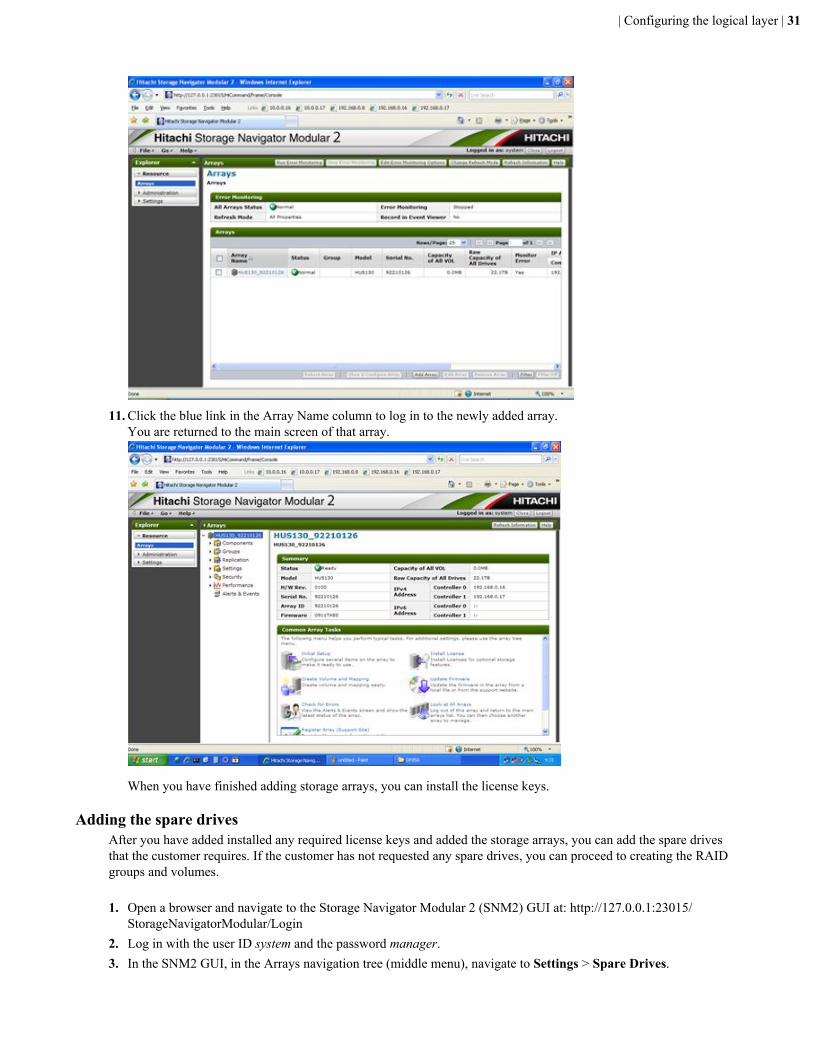
11. Click the blue link in the Array Name column to log in to the newly added array.You are returned to the main screen of that array.
When you have finished adding storage arrays, you can install the license keys.
Adding the spare drivesAfter you have added installed any required license keys and added the storage arrays, you can add the spare drivesthat the customer requires. If the customer has not requested any spare drives, you can proceed to creating the RAIDgroups and volumes.
1. Open a browser and navigate to the Storage Navigator Modular 2 (SNM2) GUI at: http://127.0.0.1:23015/StorageNavigatorModular/Login
2. Log in with the user ID system and the password manager.3. In the SNM2 GUI, in the Arrays navigation tree (middle menu), navigate to Settings > Spare Drives.
| Configuring the logical layer | 31
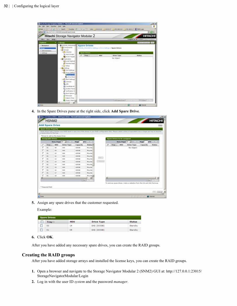
4. In the Spare Drives pane at the right side, click Add Spare Drive.
5. Assign any spare drives that the customer requested.
Example:
6. Click OK.
After you have added any necessary spare drives, you can create the RAID groups.
Creating the RAID groupsAfter you have added storage arrays and installed the license keys, you can create the RAID groups.
1. Open a browser and navigate to the Storage Navigator Modular 2 (SNM2) GUI at: http://127.0.0.1:23015/StorageNavigatorModular/Login
2. Log in with the user ID system and the password manager.
32 | | Configuring the logical layer
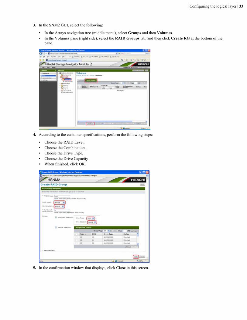
3. In the SNM2 GUI, select the following:
• In the Arrays navigation tree (middle menu), select Groups and then Volumes.• In the Volumes pane (right side), select the RAID Groups tab, and then click Create RG at the bottom of the
pane.
4. According to the customer specifications, perform the following steps:
• Choose the RAID Level.• Choose the Combination.• Choose the Drive Type.• Choose the Drive Capacity• When finished, click OK.
5. In the confirmation window that displays, click Close in this screen.
| Configuring the logical layer | 33
6. Repeat this procedure for the remaining drives for which you want to create RAID groups.When you have finished creating the RAID groups, you can create the necessary volumes.
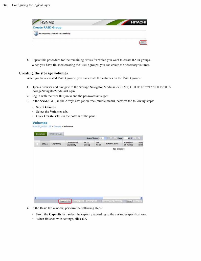
Creating the storage volumesAfter you have created RAID groups, you can create the volumes on the RAID groups.
1. Open a browser and navigate to the Storage Navigator Modular 2 (SNM2) GUI at: http://127.0.0.1:23015/StorageNavigatorModular/Login
2. Log in with the user ID system and the password manager.3. In the SNM2 GUI, in the Arrays navigation tree (middle menu), perform the following steps:
• Select Groups.• Select the Volumes tab.• Click Create VOL in the bottom of the pane.
4. In the Basic tab window, perform the following steps:
• From the Capacity list, select the capacity according to the customer specifications.• When finished with settings, click OK
34 | | Configuring the logical layer
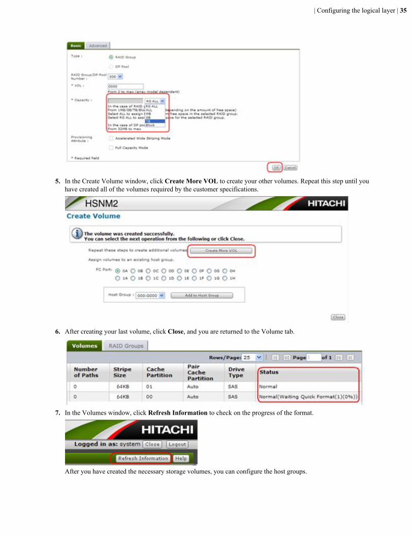
5. In the Create Volume window, click Create More VOL to create your other volumes. Repeat this step until youhave created all of the volumes required by the customer specifications.
6. After creating your last volume, click Close, and you are returned to the Volume tab.
7. In the Volumes window, click Refresh Information to check on the progress of the format.
After you have created the necessary storage volumes, you can configure the host groups.
| Configuring the logical layer | 35
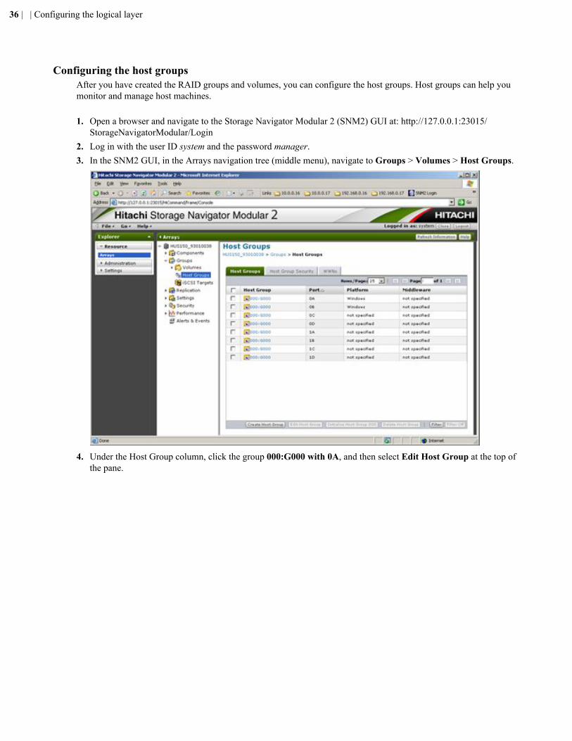
Configuring the host groupsAfter you have created the RAID groups and volumes, you can configure the host groups. Host groups can help youmonitor and manage host machines.
1. Open a browser and navigate to the Storage Navigator Modular 2 (SNM2) GUI at: http://127.0.0.1:23015/StorageNavigatorModular/Login
2. Log in with the user ID system and the password manager.3. In the SNM2 GUI, in the Arrays navigation tree (middle menu), navigate to Groups > Volumes > Host Groups.
4. Under the Host Group column, click the group 000:G000 with 0A, and then select Edit Host Group at the top ofthe pane.
36 | | Configuring the logical layer
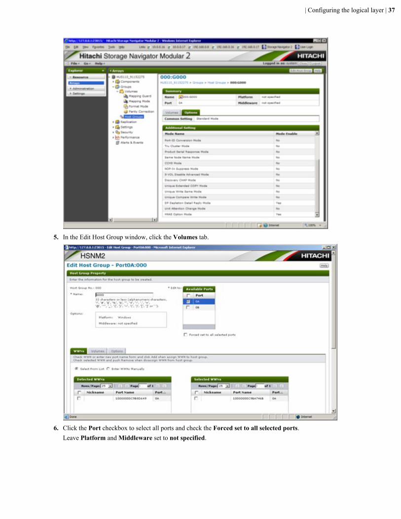
5. In the Edit Host Group window, click the Volumes tab.
6. Click the Port checkbox to select all ports and check the Forced set to all selected ports.Leave Platform and Middleware set to not specified.
| Configuring the logical layer | 37
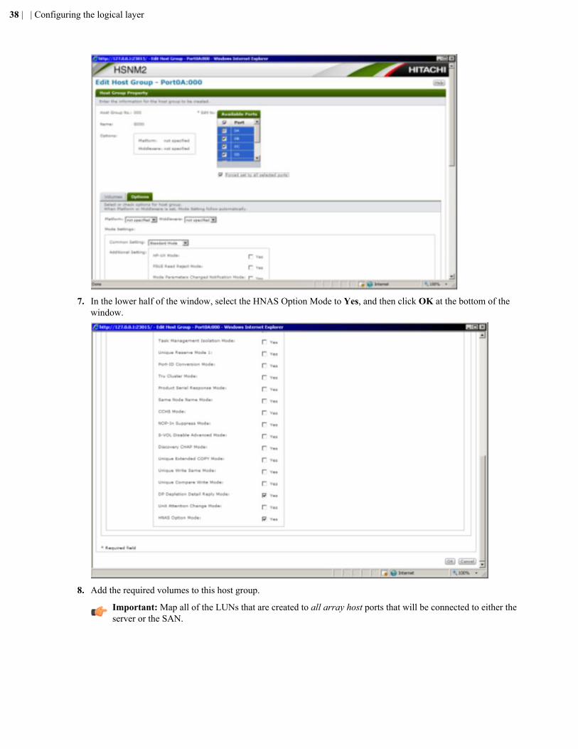
7. In the lower half of the window, select the HNAS Option Mode to Yes, and then click OK at the bottom of thewindow.
8. Add the required volumes to this host group.
Important: Map all of the LUNs that are created to all array host ports that will be connected to either theserver or the SAN.
38 | | Configuring the logical layer
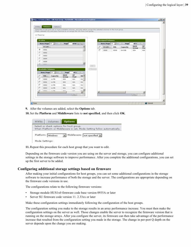
9. After the volumes are added, select the Options tab.10. Set the Platform and Middleware lists to not specified, and then click OK.
11. Repeat this procedure for each host group that you want to edit.
Depending on the firmware code version you are using on the server and storage, you can configure additionalsettings in the storage software to improve performance. After you complete the additional configurations, you can setup the first server to be added.
Configuring additional storage settings based on firmwareAfter making your initial configurations for host groups, you can set some additional configurations in the storagesoftware to increase performance of both the storage and the server. The configurations are appropriate depending onthe firmware code versions in use.
The configurations relate to the following firmware versions:
• Storage module HUS1x0 firmware code base version 0935A or later• Server SU firmware code version 11. 2.33xx or later
Make these configuration settings immediately following the configuration of the host groups.
The configuration setting you make to the storage results in an array performance increase. You must then make theconfiguration settings on the server as well. Those changes enable the server to recognize the firmware version that isrunning on the storage arrays. After you configure the server, its firmware can then take advantage of the performanceincrease that resulted from the configuration setting you made in the storage. The change in per-port Q depth on theserver depends upon the change you are making.
| Configuring the logical layer | 39
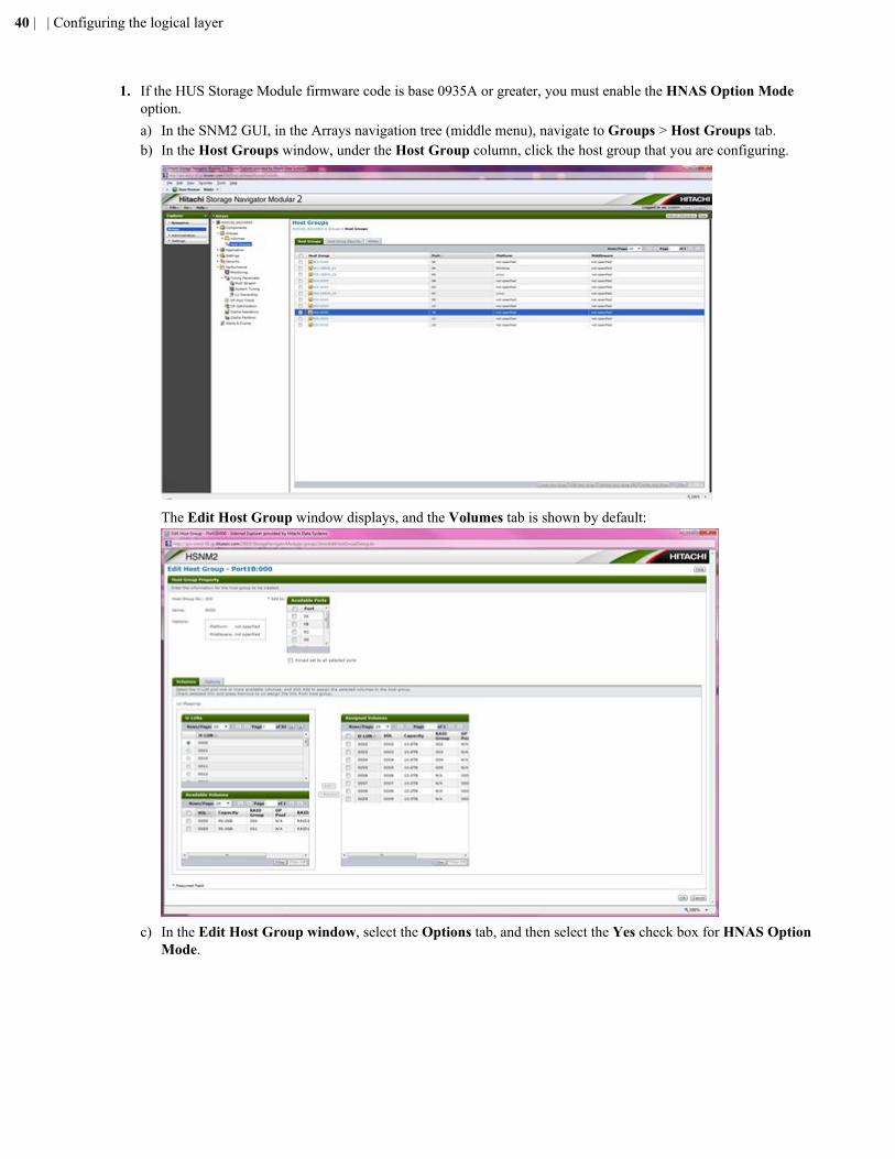
1. If the HUS Storage Module firmware code is base 0935A or greater, you must enable the HNAS Option Modeoption.a) In the SNM2 GUI, in the Arrays navigation tree (middle menu), navigate to Groups > Host Groups tab.b) In the Host Groups window, under the Host Group column, click the host group that you are configuring.
The Edit Host Group window displays, and the Volumes tab is shown by default:
c) In the Edit Host Group window, select the Options tab, and then select the Yes check box for HNAS OptionMode.
40 | | Configuring the logical layer
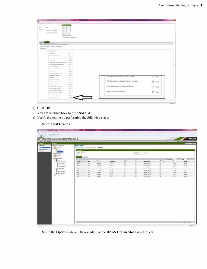
d) Click OK.You are returned back to the SNM2 GUI.
e) Verify the setting by performing the following steps:
• Select Host Groups.
• Select the Options tab, and then verify that the HNAS Option Mode is set to Yes.
| Configuring the logical layer | 41
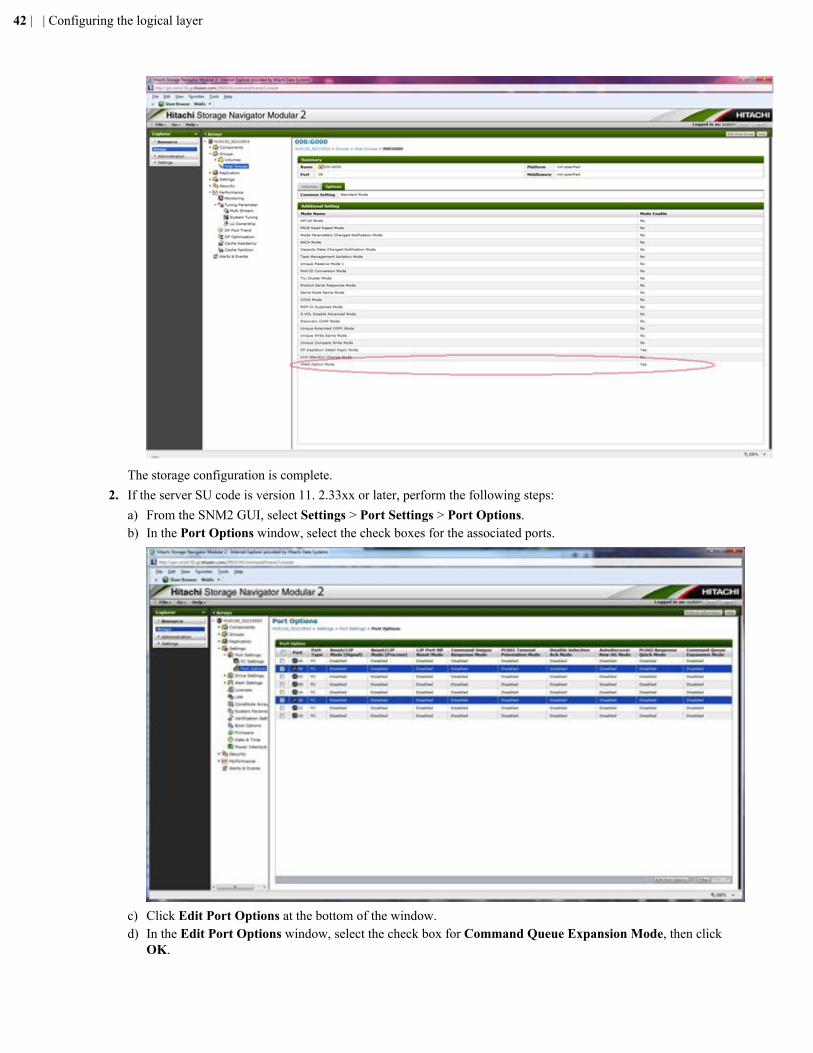
The storage configuration is complete.2. If the server SU code is version 11. 2.33xx or later, perform the following steps:
a) From the SNM2 GUI, select Settings > Port Settings > Port Options.b) In the Port Options window, select the check boxes for the associated ports.
c) Click Edit Port Options at the bottom of the window.d) In the Edit Port Options window, select the check box for Command Queue Expansion Mode, then click
OK.
42 | | Configuring the logical layer
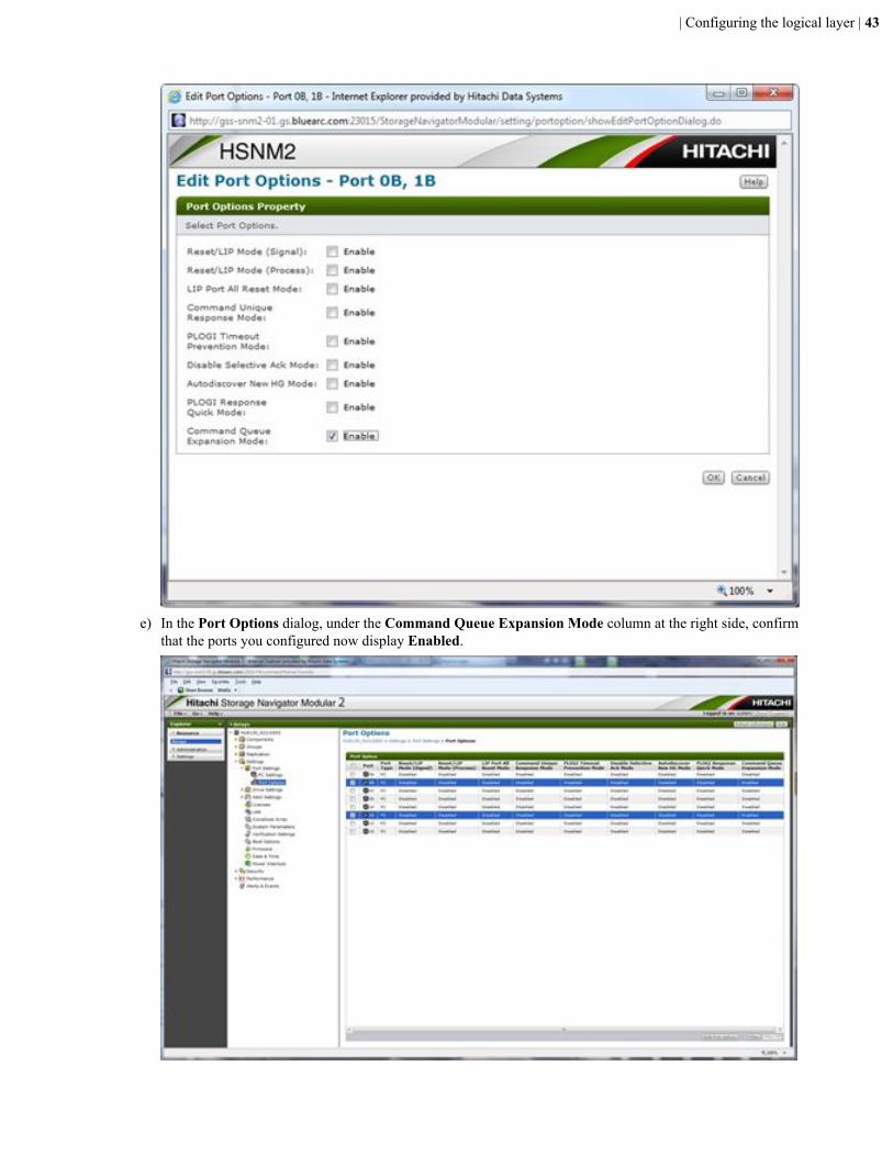
e) In the Port Options dialog, under the Command Queue Expansion Mode column at the right side, confirmthat the ports you configured now display Enabled.
| Configuring the logical layer | 43
The server firmware can now take advantage of the performance increase that resulted from the configurationsetting you made in the storage. The change in per-port Q depth on the server depends upon the change youjust made.
To take advantage of the increase on the storage array, you must perform the described two-prongedimplementation on the server.
The server must be able to recognize that the array is running firmware version 09.35A. Before making thischange, the server was not aware of the version of the code running on the array.
After you complete the additional configurations, you can set up the first server to be added.
Setting up the OS and software on an SMUThe Hitachi NAS Platform Series 4000 or Series 4000 system management unit (SMU) supports the following:
• CentOS version 6.2 and 4.8• SMU software version 8, 10.2, and 11
You must install the OS before installing the SMU software.
An external SMU is required for clustered server systems.
If you are running a single server, the SMU can be either external or embedded in the server. An embedded SMUdoes not have its own OS.
Configuring a server administrative IP to access embedded SMUsThis command configures the administrative EVS public IP address of Eth0 on the server, which is used to access thesystem using Web Manager.
Allow the server up to 10 minutes after powering on to ensure it fully starts all processes.
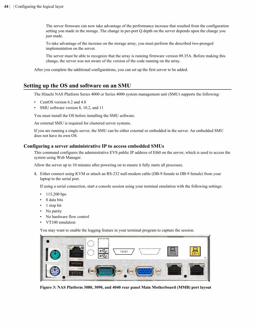
1. Either connect using KVM or attach an RS-232 null-modem cable (DB-9 female to DB-9 female) from yourlaptop to the serial port.
If using a serial connection, start a console session using your terminal emulation with the following settings:
• 115,200 bps• 8 data bits• 1 stop bit• No parity• No hardware flow control• VT100 emulation
You may want to enable the logging feature in your terminal program to capture the session.
Figure 3: NAS Platform 3080, 3090, and 4040 rear panel Main Motherboard (MMB) port layout
44 | | Configuring the logical layer
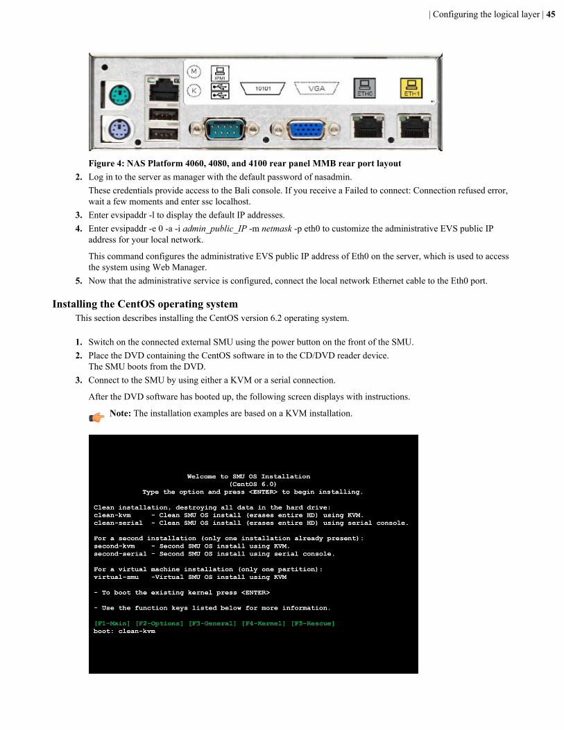
Figure 4: NAS Platform 4060, 4080, and 4100 rear panel MMB rear port layout2. Log in to the server as manager with the default password of nasadmin.
These credentials provide access to the Bali console. If you receive a Failed to connect: Connection refused error,wait a few moments and enter ssc localhost.
3. Enter evsipaddr -l to display the default IP addresses.4. Enter evsipaddr -e 0 -a -i admin_public_IP -m netmask -p eth0 to customize the administrative EVS public IP
address for your local network.
This command configures the administrative EVS public IP address of Eth0 on the server, which is used to accessthe system using Web Manager.
5. Now that the administrative service is configured, connect the local network Ethernet cable to the Eth0 port.
Installing the CentOS operating systemThis section describes installing the CentOS version 6.2 operating system.
1. Switch on the connected external SMU using the power button on the front of the SMU.2. Place the DVD containing the CentOS software in to the CD/DVD reader device.
The SMU boots from the DVD.3. Connect to the SMU by using either a KVM or a serial connection.
After the DVD software has booted up, the following screen displays with instructions.
Note: The installation examples are based on a KVM installation.
| Configuring the logical layer | 45
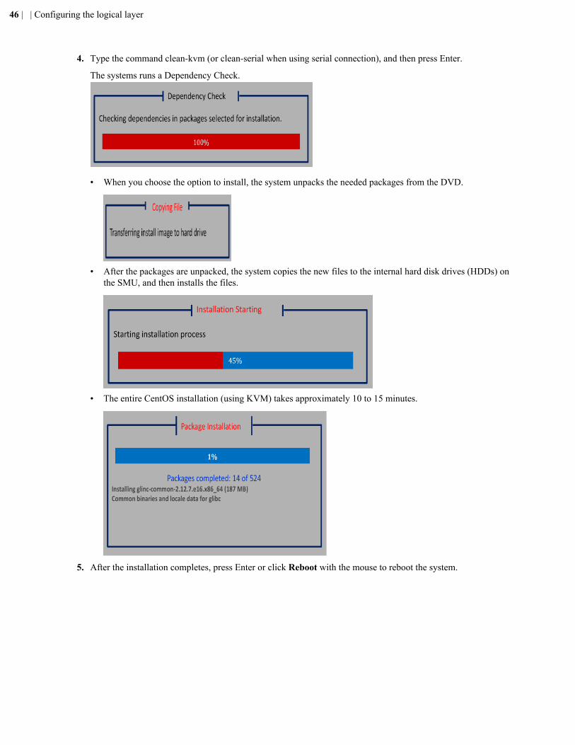
4. Type the command clean-kvm (or clean-serial when using serial connection), and then press Enter.
The systems runs a Dependency Check.
• When you choose the option to install, the system unpacks the needed packages from the DVD.
• After the packages are unpacked, the system copies the new files to the internal hard disk drives (HDDs) onthe SMU, and then installs the files.
• The entire CentOS installation (using KVM) takes approximately 10 to 15 minutes.
5. After the installation completes, press Enter or click Reboot with the mouse to reboot the system.
46 | | Configuring the logical layer
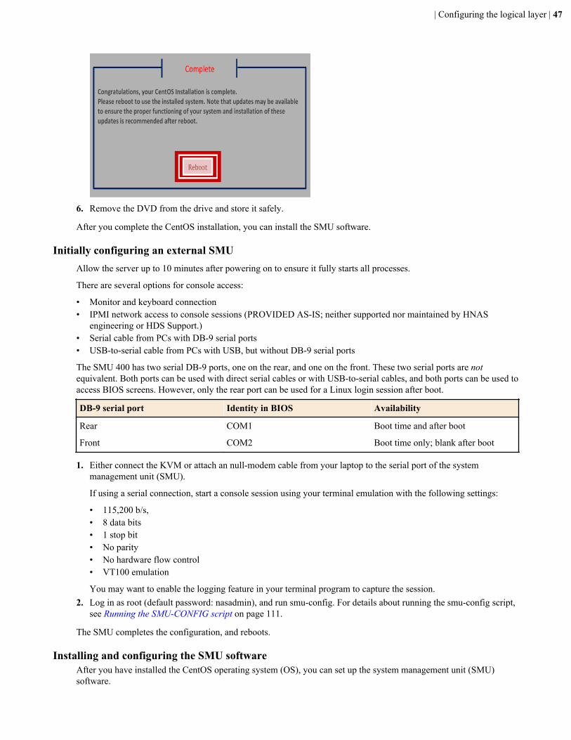
6. Remove the DVD from the drive and store it safely.
After you complete the CentOS installation, you can install the SMU software.
Initially configuring an external SMUAllow the server up to 10 minutes after powering on to ensure it fully starts all processes.
There are several options for console access:
• Monitor and keyboard connection• IPMI network access to console sessions (PROVIDED AS-IS; neither supported nor maintained by HNAS
engineering or HDS Support.)• Serial cable from PCs with DB-9 serial ports• USB-to-serial cable from PCs with USB, but without DB-9 serial ports
The SMU 400 has two serial DB-9 ports, one on the rear, and one on the front. These two serial ports are notequivalent. Both ports can be used with direct serial cables or with USB-to-serial cables, and both ports can be used toaccess BIOS screens. However, only the rear port can be used for a Linux login session after boot.
DB-9 serial port Identity in BIOS Availability
Rear COM1 Boot time and after boot
Front COM2 Boot time only; blank after boot
1. Either connect the KVM or attach an null-modem cable from your laptop to the serial port of the systemmanagement unit (SMU).
If using a serial connection, start a console session using your terminal emulation with the following settings:
• 115,200 b/s,• 8 data bits• 1 stop bit• No parity• No hardware flow control• VT100 emulation
You may want to enable the logging feature in your terminal program to capture the session.2. Log in as root (default password: nasadmin), and run smu-config. For details about running the smu-config script,
see Running the SMU-CONFIG script on page 111.
The SMU completes the configuration, and reboots.
Installing and configuring the SMU softwareAfter you have installed the CentOS operating system (OS), you can set up the system management unit (SMU)software.
| Configuring the logical layer | 47
Note: See Upgrading an external SMU on page 107 for details about upgrading the SMU software.
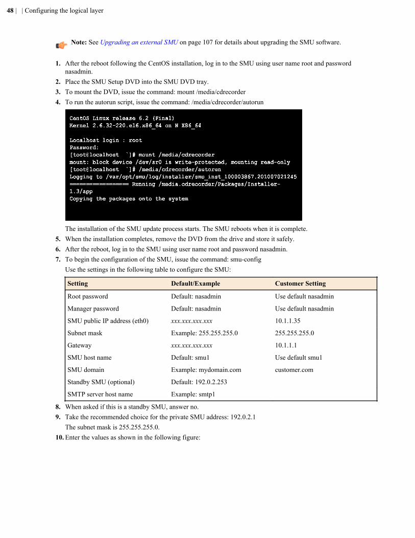
1. After the reboot following the CentOS installation, log in to the SMU using user name root and passwordnasadmin.
2. Place the SMU Setup DVD into the SMU DVD tray.3. To mount the DVD, issue the command: mount /media/cdrecorder4. To run the autorun script, issue the command: /media/cdrecorder/autorun
The installation of the SMU update process starts. The SMU reboots when it is complete.5. When the installation completes, remove the DVD from the drive and store it safely.6. After the reboot, log in to the SMU using user name root and password nasadmin.7. To begin the configuration of the SMU, issue the command: smu-config
Use the settings in the following table to configure the SMU:
Setting Default/Example Customer Setting
Root password Default: nasadmin Use default nasadmin
Manager password Default: nasadmin Use default nasadmin
SMU public IP address (eth0) xxx.xxx.xxx.xxx 10.1.1.35
Subnet mask Example: 255.255.255.0 255.255.255.0
Gateway xxx.xxx.xxx.xxx 10.1.1.1
SMU host name Default: smu1 Use default smu1
SMU domain Example: mydomain.com customer.com
Standby SMU (optional) Default: 192.0.2.253
SMTP server host name Example: smtp1
8. When asked if this is a standby SMU, answer no.9. Take the recommended choice for the private SMU address: 192.0.2.1
The subnet mask is 255.255.255.0.10. Enter the values as shown in the following figure:
48 | | Configuring the logical layer
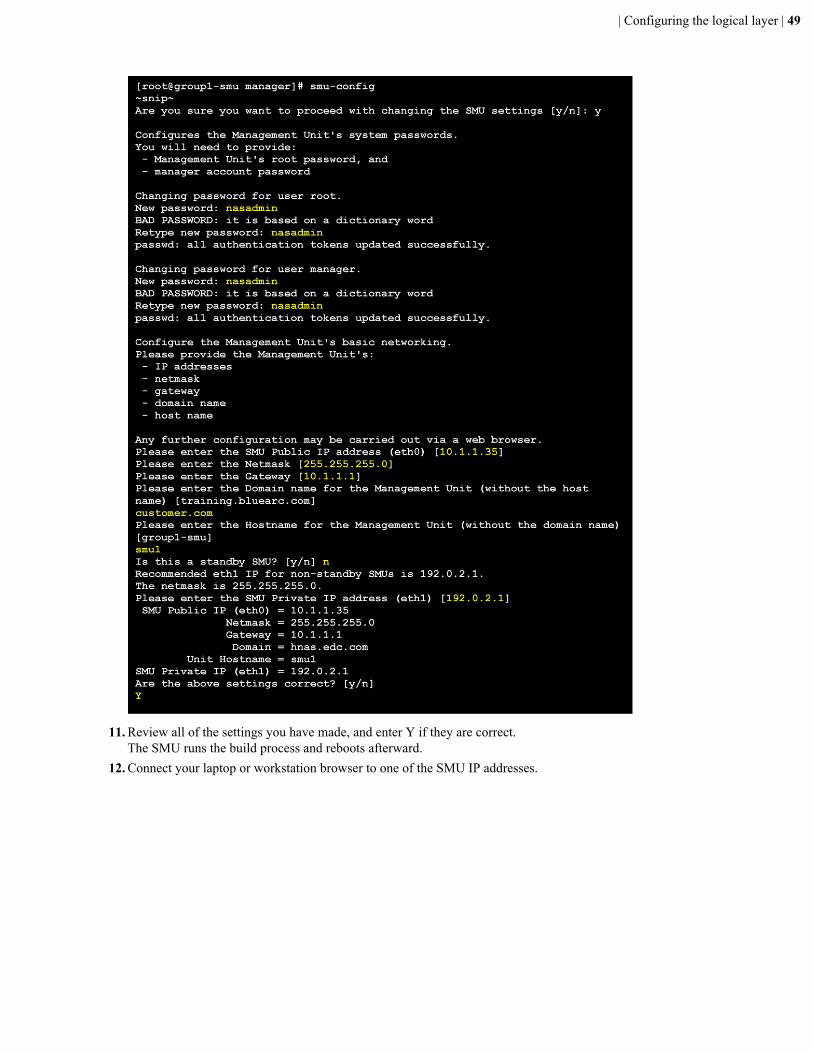
11. Review all of the settings you have made, and enter Y if they are correct.The SMU runs the build process and reboots afterward.
12. Connect your laptop or workstation browser to one of the SMU IP addresses.
| Configuring the logical layer | 49
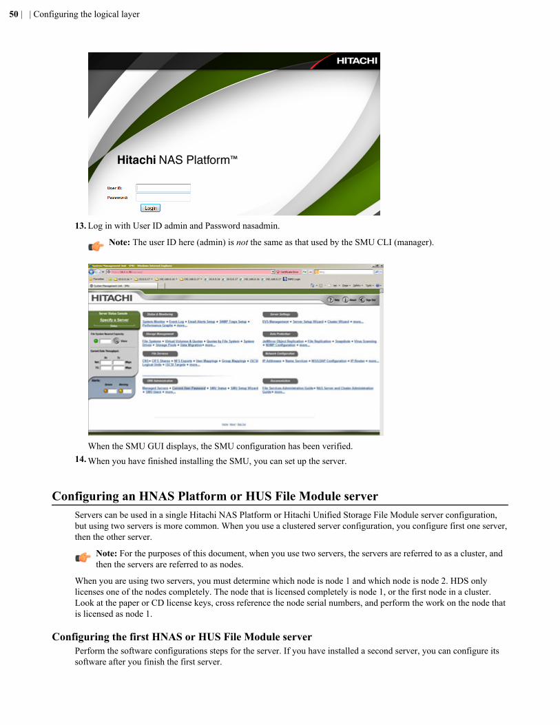
13. Log in with User ID admin and Password nasadmin.
Note: The user ID here (admin) is not the same as that used by the SMU CLI (manager).
When the SMU GUI displays, the SMU configuration has been verified.14. When you have finished installing the SMU, you can set up the server.
Configuring an HNAS Platform or HUS File Module serverServers can be used in a single Hitachi NAS Platform or Hitachi Unified Storage File Module server configuration,but using two servers is more common. When you use a clustered server configuration, you configure first one server,then the other server.
Note: For the purposes of this document, when you use two servers, the servers are referred to as a cluster, andthen the servers are referred to as nodes.
When you are using two servers, you must determine which node is node 1 and which node is node 2. HDS onlylicenses one of the nodes completely. The node that is licensed completely is node 1, or the first node in a cluster.Look at the paper or CD license keys, cross reference the node serial numbers, and perform the work on the node thatis licensed as node 1.
Configuring the first HNAS or HUS File Module serverPerform the software configurations steps for the server. If you have installed a second server, you can configure itssoftware after you finish the first server.
50 | | Configuring the logical layer
When the server initially powers on, it makes a significant amount of loud noise while its coming up. Once the loginprompt appears, wait for the noise to subside to a lower level before logging in. When the fans stop blowing loudly(not entirely, of course), the machine is ready for login.
Note: The screen output may vary slightly depending on the server model that you are configuring.
1. Connect to the server with a serial or KVM connection.2. Power on the server by applying power.
The system boots.3. Log in with the username root and the password nasadmin.
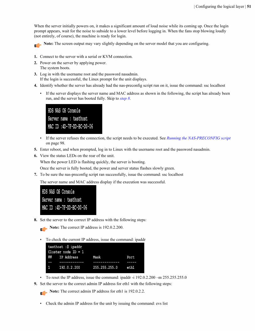
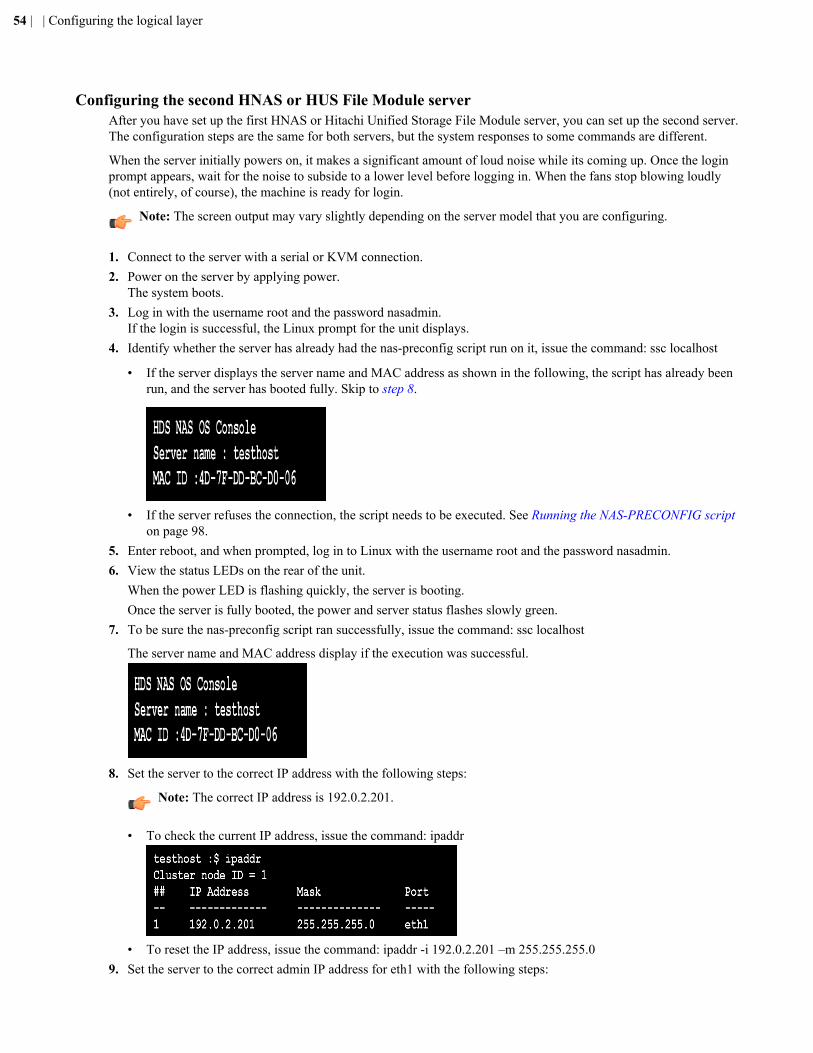
If the login is successful, the Linux prompt for the unit displays.4. Identify whether the server has already had the nas-preconfig script run on it, issue the command: ssc localhost
• If the server displays the server name and MAC address as shown in the following, the script has already beenrun, and the server has booted fully. Skip to step 8.
• If the server refuses the connection, the script needs to be executed. See Running the NAS-PRECONFIG scripton page 98.
5. Enter reboot, and when prompted, log in to Linux with the username root and the password nasadmin.6. View the status LEDs on the rear of the unit.
When the power LED is flashing quickly, the server is booting.Once the server is fully booted, the power and server status flashes slowly green.
7. To be sure the nas-preconfig script ran successfully, issue the command: ssc localhost
The server name and MAC address display if the execution was successful.
8. Set the server to the correct IP address with the following steps:
Note: The correct IP address is 192.0.2.200.
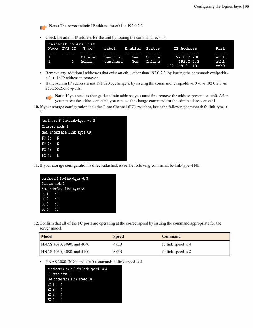
• To check the current IP address, issue the command: ipaddr
• To reset the IP address, issue the command: ipaddr -i 192.0.2.200 –m 255.255.255.09. Set the server to the correct admin IP address for eth1 with the following steps:
Note: The correct admin IP address for eth1 is 192.0.2.2.
• Check the admin IP address for the unit by issuing the command: evs list
| Configuring the logical layer | 51
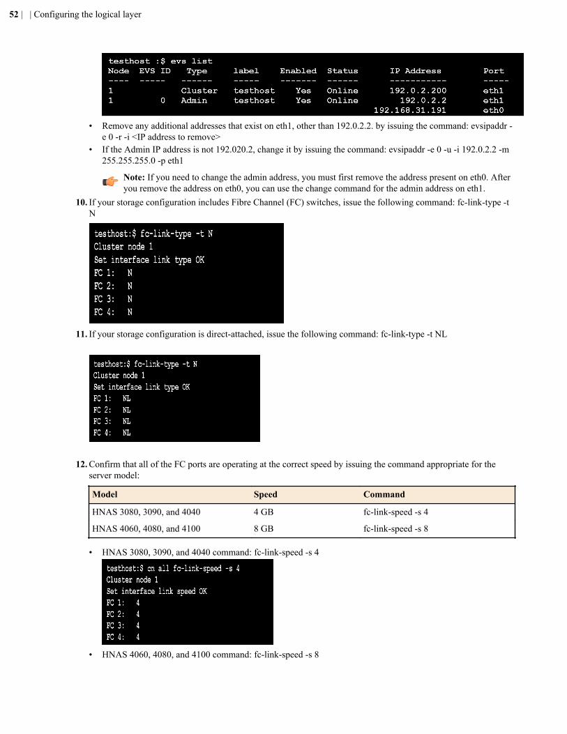
• Remove any additional addresses that exist on eth1, other than 192.0.2.2. by issuing the command: evsipaddr -e 0 -r -i <IP address to remove>
• If the Admin IP address is not 192.020.2, change it by issuing the command: evsipaddr -e 0 -u -i 192.0.2.2 -m255.255.255.0 -p eth1
Note: If you need to change the admin address, you must first remove the address present on eth0. Afteryou remove the address on eth0, you can use the change command for the admin address on eth1.
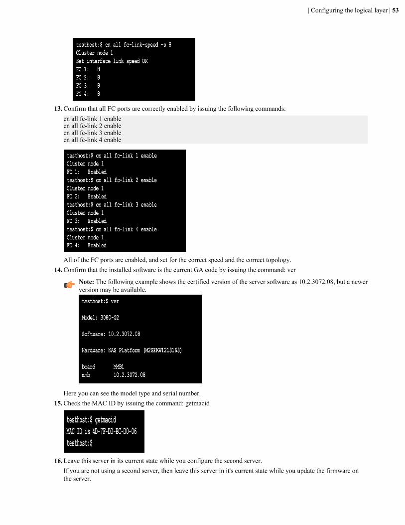
10. If your storage configuration includes Fibre Channel (FC) switches, issue the following command: fc-link-type -tN
11. If your storage configuration is direct-attached, issue the following command: fc-link-type -t NL
12. Confirm that all of the FC ports are operating at the correct speed by issuing the command appropriate for the
server model:
Model Speed Command
HNAS 3080, 3090, and 4040 4 GB fc-link-speed -s 4
HNAS 4060, 4080, and 4100 8 GB fc-link-speed -s 8
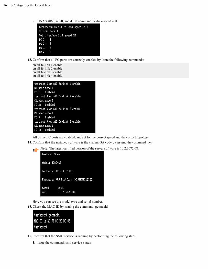
• HNAS 3080, 3090, and 4040 command: fc-link-speed -s 4
• HNAS 4060, 4080, and 4100 command: fc-link-speed -s 8
52 | | Configuring the logical layer
13. Confirm that all FC ports are correctly enabled by issuing the following commands:cn all fc-link 1 enablecn all fc-link 2 enablecn all fc-link 3 enablecn all fc-link 4 enable
All of the FC ports are enabled, and set for the correct speed and the correct topology.14. Confirm that the installed software is the current GA code by issuing the command: ver
Note: The following example shows the certified version of the server software as 10.2.3072.08, but a newerversion may be available.
Here you can see the model type and serial number.15. Check the MAC ID by issuing the command: getmacid
16. Leave this server in its current state while you configure the second server.If you are not using a second server, then leave this server in it's current state while you update the firmware onthe server.
| Configuring the logical layer | 53
Configuring the second HNAS or HUS File Module serverAfter you have set up the first HNAS or Hitachi Unified Storage File Module server, you can set up the second server.The configuration steps are the same for both servers, but the system responses to some commands are different.
When the server initially powers on, it makes a significant amount of loud noise while its coming up. Once the loginprompt appears, wait for the noise to subside to a lower level before logging in. When the fans stop blowing loudly(not entirely, of course), the machine is ready for login.
Note: The screen output may vary slightly depending on the server model that you are configuring.
1. Connect to the server with a serial or KVM connection.2. Power on the server by applying power.
The system boots.3. Log in with the username root and the password nasadmin.
If the login is successful, the Linux prompt for the unit displays.4. Identify whether the server has already had the nas-preconfig script run on it, issue the command: ssc localhost
• If the server displays the server name and MAC address as shown in the following, the script has already beenrun, and the server has booted fully. Skip to step 8.
• If the server refuses the connection, the script needs to be executed. See Running the NAS-PRECONFIG scripton page 98.
5. Enter reboot, and when prompted, log in to Linux with the username root and the password nasadmin.6. View the status LEDs on the rear of the unit.
When the power LED is flashing quickly, the server is booting.Once the server is fully booted, the power and server status flashes slowly green.
7. To be sure the nas-preconfig script ran successfully, issue the command: ssc localhost
The server name and MAC address display if the execution was successful.
8. Set the server to the correct IP address with the following steps:
Note: The correct IP address is 192.0.2.201.
• To check the current IP address, issue the command: ipaddr
• To reset the IP address, issue the command: ipaddr -i 192.0.2.201 –m 255.255.255.09. Set the server to the correct admin IP address for eth1 with the following steps:
54 | | Configuring the logical layer
Note: The correct admin IP address for eth1 is 192.0.2.3.
• Check the admin IP address for the unit by issuing the command: evs list
• Remove any additional addresses that exist on eth1, other than 192.0.2.3, by issuing the command: evsipaddr -e 0 -r -i <IP address to remove>
• If the Admin IP address is not 192.020.3, change it by issuing the command: evsipaddr -e 0 -u -i 192.0.2.3 -m255.255.255.0 -p eth1
Note: If you need to change the admin address, you must first remove the address present on eth0. Afteryou remove the address on eth0, you can use the change command for the admin address on eth1.
10. If your storage configuration includes Fibre Channel (FC) switches, issue the following command: fc-link-type -tN
11. If your storage configuration is direct-attached, issue the following command: fc-link-type -t NL
12. Confirm that all of the FC ports are operating at the correct speed by issuing the command appropriate for the
server model:
Model Speed Command
HNAS 3080, 3090, and 4040 4 GB fc-link-speed -s 4
HNAS 4060, 4080, and 4100 8 GB fc-link-speed -s 8
• HNAS 3080, 3090, and 4040 command: fc-link-speed -s 4
| Configuring the logical layer | 55
• HNAS 4060, 4080, and 4100 command: fc-link-speed -s 8
13. Confirm that all FC ports are correctly enabled by Issue the following commands:cn all fc-link 1 enablecn all fc-link 2 enablecn all fc-link 3 enablecn all fc-link 4 enable
All of the FC ports are enabled, and set for the correct speed and the correct topology.14. Confirm that the installed software is the current GA code by issuing the command: ver
Note: The latest certified version of the server software is 10.2.3072.08.
Here you can see the model type and serial number.15. Check the MAC ID by issuing the command: getmacid
16. Confirm that the SMU service is running by performing the following steps:
1. Issue the command: smu-service-status
56 | | Configuring the logical layer
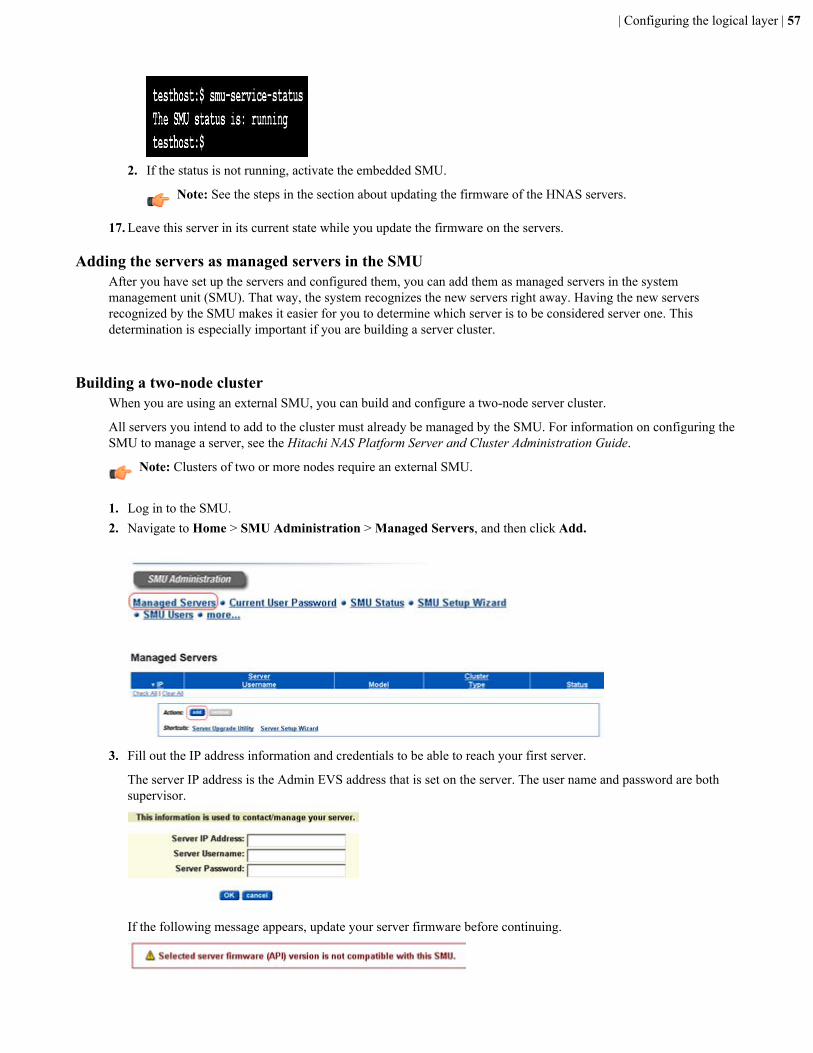
2. If the status is not running, activate the embedded SMU.
Note: See the steps in the section about updating the firmware of the HNAS servers.
17. Leave this server in its current state while you update the firmware on the servers.
Adding the servers as managed servers in the SMUAfter you have set up the servers and configured them, you can add them as managed servers in the systemmanagement unit (SMU). That way, the system recognizes the new servers right away. Having the new serversrecognized by the SMU makes it easier for you to determine which server is to be considered server one. Thisdetermination is especially important if you are building a server cluster.
Building a two-node clusterWhen you are using an external SMU, you can build and configure a two-node server cluster.
All servers you intend to add to the cluster must already be managed by the SMU. For information on configuring theSMU to manage a server, see the Hitachi NAS Platform Server and Cluster Administration Guide.
Note: Clusters of two or more nodes require an external SMU.
1. Log in to the SMU.2. Navigate to Home > SMU Administration > Managed Servers, and then click Add.
3. Fill out the IP address information and credentials to be able to reach your first server.
The server IP address is the Admin EVS address that is set on the server. The user name and password are bothsupervisor.
If the following message appears, update your server firmware before continuing.
| Configuring the logical layer | 57
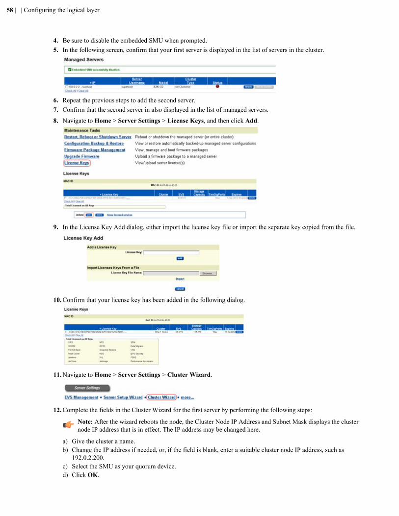
4. Be sure to disable the embedded SMU when prompted.5. In the following screen, confirm that your first server is displayed in the list of servers in the cluster.
6. Repeat the previous steps to add the second server.7. Confirm that the second server in also displayed in the list of managed servers.
8. Navigate to Home > Server Settings > License Keys, and then click Add.
9. In the License Key Add dialog, either import the license key file or import the separate key copied from the file.
10. Confirm that your license key has been added in the following dialog.
11. Navigate to Home > Server Settings > Cluster Wizard.
12. Complete the fields in the Cluster Wizard for the first server by performing the following steps:
Note: After the wizard reboots the node, the Cluster Node IP Address and Subnet Mask displays the clusternode IP address that is in effect. The IP address may be changed here.
a) Give the cluster a name.b) Change the IP address if needed, or, if the field is blank, enter a suitable cluster node IP address, such as
192.0.2.200.c) Select the SMU as your quorum device.d) Click OK.
58 | | Configuring the logical layer
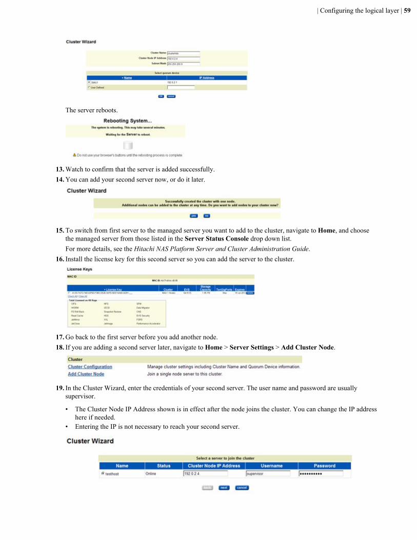
The server reboots.
13. Watch to confirm that the server is added successfully.14. You can add your second server now, or do it later.
15. To switch from first server to the managed server you want to add to the cluster, navigate to Home, and choosethe managed server from those listed in the Server Status Console drop down list.For more details, see the Hitachi NAS Platform Server and Cluster Administration Guide.
16. Install the license key for this second server so you can add the server to the cluster.
17. Go back to the first server before you add another node.18. If you are adding a second server later, navigate to Home > Server Settings > Add Cluster Node.
19. In the Cluster Wizard, enter the credentials of your second server. The user name and password are usuallysupervisor.
• The Cluster Node IP Address shown is in effect after the node joins the cluster. You can change the IP addresshere if needed.
• Entering the IP is not necessary to reach your second server.
| Configuring the logical layer | 59

20. Navigate to Home > SMU Administration > Managed Servers, and confirm that a server is displayed andshows the status of Clustered.
Note: Only a single cluster entry can be visible.
Your dual-server cluster had been successfully built.
Zoning and configuring the Fibre Channel switchAfter you have set up and tested the server, storage, and system management unit (SMU), you can configure zoningand the settings for the Fibre Channel (FC) switch.
Note: The Fibre Channel (FC) switch described in this section is a Brocade switch. The system also supportsswitches from other vendors, including Cisco, and others.
The following table show the FC port speeds for the server models.
Server model Port speed
HNAS 3080, HNAS 3090, or HNAS 4040 4GB
HNAS 4060, HNAS 4080 , or HNAS 4100 8GB
1. Connect the serial cable into the left port of the bottom switch in the rack.The bottom FC switch is the primary switch.
2. Open the PuTTY software and configure it for a serial connection:a) Select Session in the navigation tree, and then set the following:
• Serial line to connect to: COM1• Speed: 9600• Connection type: Serial• Close window on exit: Only on clean exit
b) Select Serial in the navigation tree, and set the following:
• Speed (Baud): 9600• Data bits: 8• Stop bits: 1• Parity: None• Flow control: None
c) Click Open.A black command screen displays.
3. Turn on the power to the primary (bottom) FC switch.
Note: Do not turn on the other FC switch.
Text will start running in the command screen.4. After the text in the screen stops running, press Enter, and then log in with the user name admin and the password
password.5. When asked to change all the account passwords, change all of them to nasadmin.6. When you are returned to the Admin prompt, set the IP addresses by issuing the command: ipaddrset
The IP address for this switch is 10.1.1.254.7. After you have set the IP address, exit the PuTTY software screen.8. Connect the LAN cable to the right port on the primary (bottom) switch.9. Open a browser window and enter the IP address of the bottom switch in the address bar.
This is the IP address you just set.
60 | | Configuring the logical layer
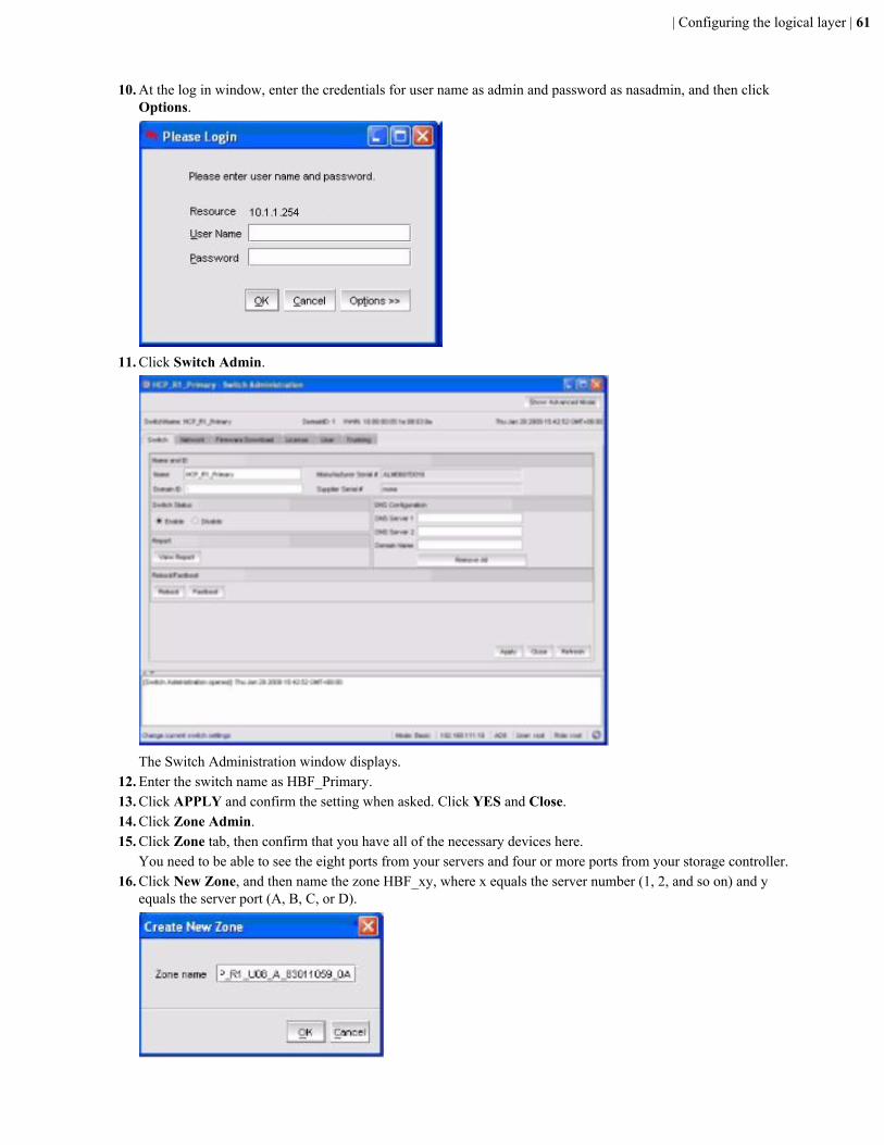
10. At the log in window, enter the credentials for user name as admin and password as nasadmin, and then clickOptions.
11. Click Switch Admin.
The Switch Administration window displays.12. Enter the switch name as HBF_Primary.13. Click APPLY and confirm the setting when asked. Click YES and Close.14. Click Zone Admin.15. Click Zone tab, then confirm that you have all of the necessary devices here.
You need to be able to see the eight ports from your servers and four or more ports from your storage controller.16. Click New Zone, and then name the zone HBF_xy, where x equals the server number (1, 2, and so on) and y
equals the server port (A, B, C, or D).
| Configuring the logical layer | 61
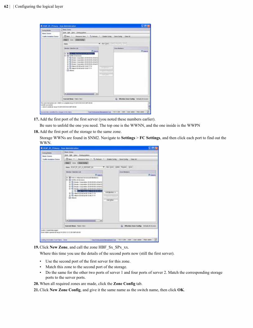
17. Add the first port of the first server (you noted these numbers earlier).Be sure to unfold the one you need. The top one is the WWNN, and the one inside is the WWPN
18. Add the first port of the storage to the same zone.Storage WWNs are found in SNM2. Navigate to Settings > FC Settings, and then click each port to find out theWWN.
19. Click New Zone, and call the zone HBF_Sx_SPx_xx.Where this time you use the details of the second ports now (still the first server).
• Use the second port of the first server for this zone.• Match this zone to the second port of the storage.• Do the same for the other two ports of server 1 and four ports of server 2. Match the corresponding storage
ports to the server ports.20. When all required zones are made, click the Zone Config tab.21. Click New Zone Config, and give it the same name as the switch name, then click OK.
62 | | Configuring the logical layer
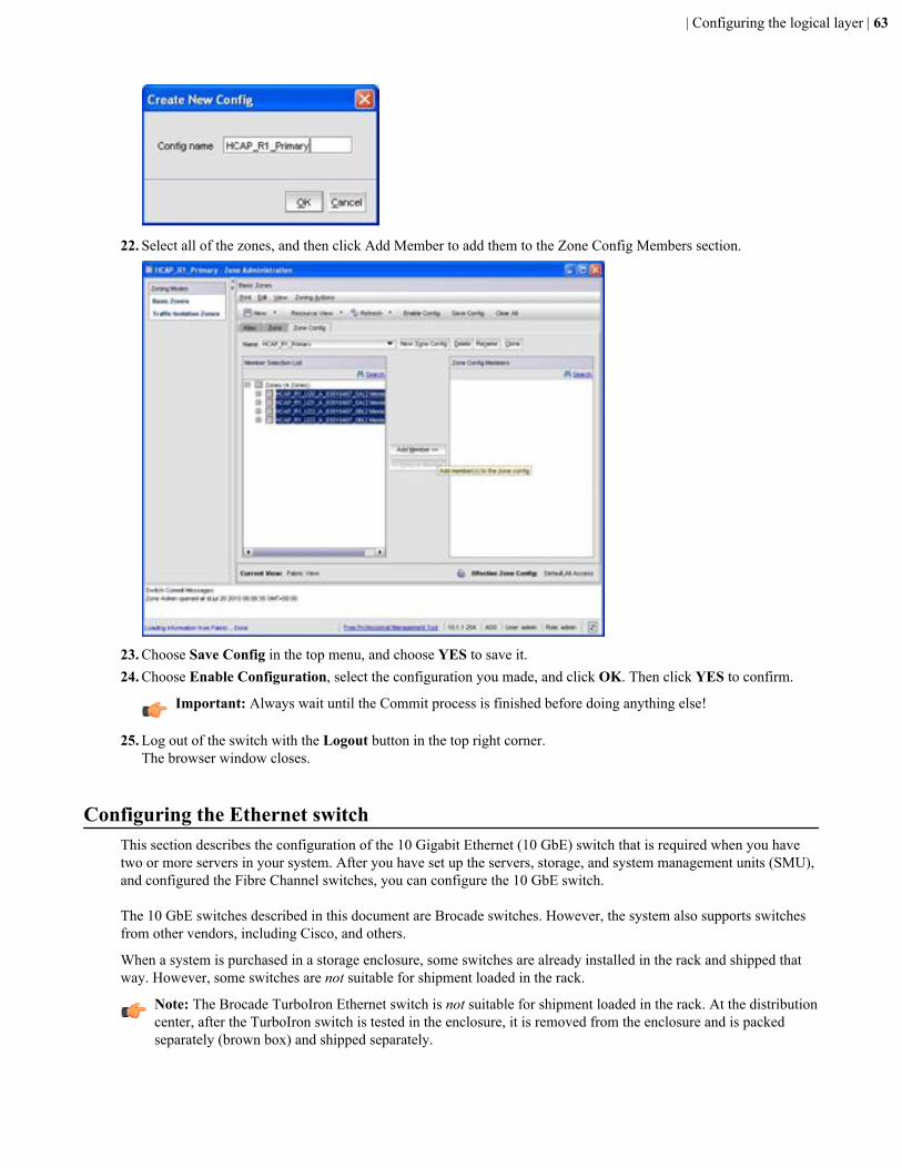
22. Select all of the zones, and then click Add Member to add them to the Zone Config Members section.
23. Choose Save Config in the top menu, and choose YES to save it.24. Choose Enable Configuration, select the configuration you made, and click OK. Then click YES to confirm.
Important: Always wait until the Commit process is finished before doing anything else!
25. Log out of the switch with the Logout button in the top right corner.The browser window closes.
Configuring the Ethernet switchThis section describes the configuration of the 10 Gigabit Ethernet (10 GbE) switch that is required when you havetwo or more servers in your system. After you have set up the servers, storage, and system management units (SMU),and configured the Fibre Channel switches, you can configure the 10 GbE switch.
The 10 GbE switches described in this document are Brocade switches. However, the system also supports switchesfrom other vendors, including Cisco, and others.
When a system is purchased in a storage enclosure, some switches are already installed in the rack and shipped thatway. However, some switches are not suitable for shipment loaded in the rack.
Note: The Brocade TurboIron Ethernet switch is not suitable for shipment loaded in the rack. At the distributioncenter, after the TurboIron switch is tested in the enclosure, it is removed from the enclosure and is packedseparately (brown box) and shipped separately.
| Configuring the logical layer | 63

Configuring the Ethernet switch initial setupUse these steps to configure the initial set up of the 10 Gigabit Ethernet (10 GbE) switch.
Note: The 10 GbE switch described in this section is a TurboIron 24X 10 GbE switch (TX24). The system alsosupports 10 GbE switches from other vendors, including Cisco and others.
1. Verify the proper operation of the switch by performing the following steps:a) Connect a straight-through serial cable to the switch's management serial port.b) Start the Serial client software (PuTTy or other).c) Power up the switch to be configured and observe the status LEDs for faults.
• The LEDs on the power supply (AC OK) and system power LED (pwr) display as solid green.• The 10 GbE port LEDs are lit while the device performs diagnostics. After the diagnostics tests complete,
the LEDs are dark except for those that are attached by cables to other devices.• If the links on these cables are good and the connected device is powered on, the link LEDs light.
2. Set the passwords by performing the following steps:
Note: As a default out of the box, there is no password assigned. Set all passwords to the HDSmanufacturing defaults.
a) To initiate the console connection, press Enter.b) Type enable and press Enter at the TX24 Switch # prompt.
The system responds: No password has been assigned yet...c) Type erase startup-config and press Enter at the TX24 Switch # prompt.
This will erase any factory test configuration.The system responds: Erase startup-config failed or config empty
d) Type configure terminal and press Enter at the TX24 Switch # prompt.The switch enters configuration mode.
e) Type enable super-user-password password and press Enter at the TX24 Switch (config) # prompt.Where password is set to ganymede, which is the manufacturing default password.
3. Configure the IP Settings by performing the following steps:a) Configure the Ethernet management LAN port on the switch for the SMU private management network.
The port on each switch is connected to the SMU private network. Therefore, the IP address must beconfigured with appropriate settings for use on this network. Set the gateway address to 192.0.2.1, which is theSMU IP address.
Use the following IP address settings for the switches within a single storage system:
Note: You can use up to IP Address 192.0.2.195 for the 16th switch.
IP address Brocade TurboIron 24X 10 GbE switch
192.0.2.180 1st
192.0.2.181 2nd
192.0.2.182 3rd
b) Type ip address 192.0.2.18x /8 and press Enter at the TX24 Switch (config) # prompt.Where x is set as the IP address described earlier (180, 181, 182, and so on) and the length is set to 8.
c) Type ip default-gateway 192.0.2.1 and press Enter at the TX24 Switch (config) # prompt.The gateway has to be set the same as the SMU private IP address.
4. To enable the jumbo frames, issue the command: e jumbo and press Enter at theTX24 Switch (config) # prompt.The default is disabled.The system returns: Jumbo mode setting requires a reload to take effect!
64 | | Configuring the logical layer

5. To disable the Spanning Tree, issue the command: e no spanning-tree and press Enter at the TX24 Switch (config)# prompt.
6. To configure the 802.1p priority mapping, perform the following steps at the TX24 Switch (config) # prompt:
Note: This switch does not use the recommended default priority mapping, so some priorities need to beadjusted.
a) Issue the command: e qos tagged-priority 0 qosp2 and press Enter.The system returns: 802.1p priority 0 mapped to qos profile qosp2
b) Issue the command: e qos tagged-priority 1 qosp0 and press Enter.The system returns: 802.1p priority 1 mapped to qos profile qosp0
c) Issue the command: e qos tagged-priority 2 qosp1 and press Enter.The system returns: 802.1p priority 2 mapped to qos profile qosp1
d) Issue the command: qos mechanism strict and press Enter.The system returns: bandwidth scheduling mechanism: strict priority Qos profile bandwidth percentages areignored
7. Configure VLANs for multiple clusters by performing the following steps:
Note: You must perform this step when switches are shared by multiple clusters. Each cluster must have itsown VLAN. It may be helpful to give each VLAN the same name as its cluster. The Spanning Tree must beexplicitly disabled on each new VLAN created. Following is an example.
1. To add the untagged ports ethe 1 to 6 , issue the following commands and press Enter as indicated for each:
• Type vlan 10 name Cluster-1 and press Enter at theTX24 Switch (config) # prompt.• Type no spanning-tree and press Enter at theTX24 Switch (config-vlan-10) # prompt.• Type untagged ethernet 1 to 6 and press Enter at theTX24 Switch (config-vlan-10) # prompt.
The system returns: Added untagged port (s) ethe 1 to 6 to port-vlan102. To add the untagged ports ethe 7 to 12 , issue the following commands and press Enter as indicated for each:
• Type vlan 11 name Cluster-2 and press Enter at theTX24 Switch ( config-vlan-10) # prompt.• Type no spanning-tree and press Enter at theTX24 Switch (config-vlan-10) # prompt.• Type untagged ethernet 7 to 12 and press Enter at theTX24 Switch (config-vlan-10) # prompt.
The system returns: Added untagged port (s) ethe 7 to 12 to port-vlan103. To finish, issue the command: exit and press Enter at the TX24 Switch (config-vlan-11) # prompt.
8. To configure Hostname Settings, issue the command: hostname TX24_192_0_2_<xxx> and press Enter attheTX24 Switch (config) # prompt.
Where <xxx> are the last three digits of IP address specified for the switch in the IP settings section above.
Give each switch in the storage system a name so that it can be easily identified on the private network. Use astandard naming convention.
You can use the command show running-config to confirm the new configuration is correctly configured beforesaving it to the switch.
9. To save the configuration, perform the following steps at the TX24_192_0_2_<xxx>(config) # prompt:a) Issue the command: exit and press Enter.b) Issue the command: write memory and press Enter.
Note: Jumbo frames and trunking do not become active until the switch is rebooted.
The system returns: Write startup-config done.c) Issue the command: reload and press Enter.d) At the Are you sure? prompt, type y and press Enter.
This step halts the system and performs a warm restart. After the restart, the configuration is now saved on theswitch.
| Configuring the logical layer | 65
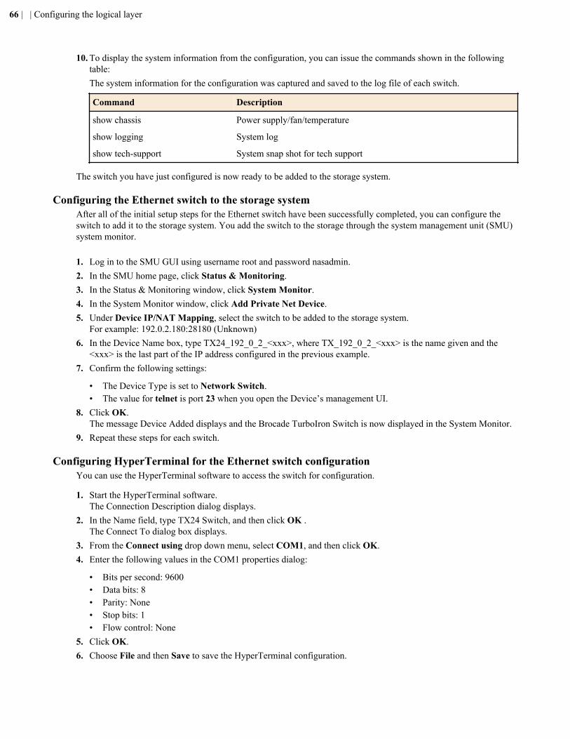
10. To display the system information from the configuration, you can issue the commands shown in the followingtable:The system information for the configuration was captured and saved to the log file of each switch.
Command Description
show chassis Power supply/fan/temperature
show logging System log
show tech-support System snap shot for tech support
The switch you have just configured is now ready to be added to the storage system.
Configuring the Ethernet switch to the storage systemAfter all of the initial setup steps for the Ethernet switch have been successfully completed, you can configure theswitch to add it to the storage system. You add the switch to the storage through the system management unit (SMU)system monitor.
1. Log in to the SMU GUI using username root and password nasadmin.2. In the SMU home page, click Status & Monitoring.3. In the Status & Monitoring window, click System Monitor.4. In the System Monitor window, click Add Private Net Device.5. Under Device IP/NAT Mapping, select the switch to be added to the storage system.
For example: 192.0.2.180:28180 (Unknown)6. In the Device Name box, type TX24_192_0_2_<xxx>, where TX_192_0_2_<xxx> is the name given and the
<xxx> is the last part of the IP address configured in the previous example.7. Confirm the following settings:
• The Device Type is set to Network Switch.• The value for telnet is port 23 when you open the Device’s management UI.
8. Click OK.The message Device Added displays and the Brocade TurboIron Switch is now displayed in the System Monitor.
9. Repeat these steps for each switch.
Configuring HyperTerminal for the Ethernet switch configurationYou can use the HyperTerminal software to access the switch for configuration.
1. Start the HyperTerminal software.The Connection Description dialog displays.
2. In the Name field, type TX24 Switch, and then click OK .The Connect To dialog box displays.
3. From the Connect using drop down menu, select COM1, and then click OK.4. Enter the following values in the COM1 properties dialog:
• Bits per second: 9600• Data bits: 8• Parity: None• Stop bits: 1• Flow control: None
5. Click OK.6. Choose File and then Save to save the HyperTerminal configuration.
66 | | Configuring the logical layer
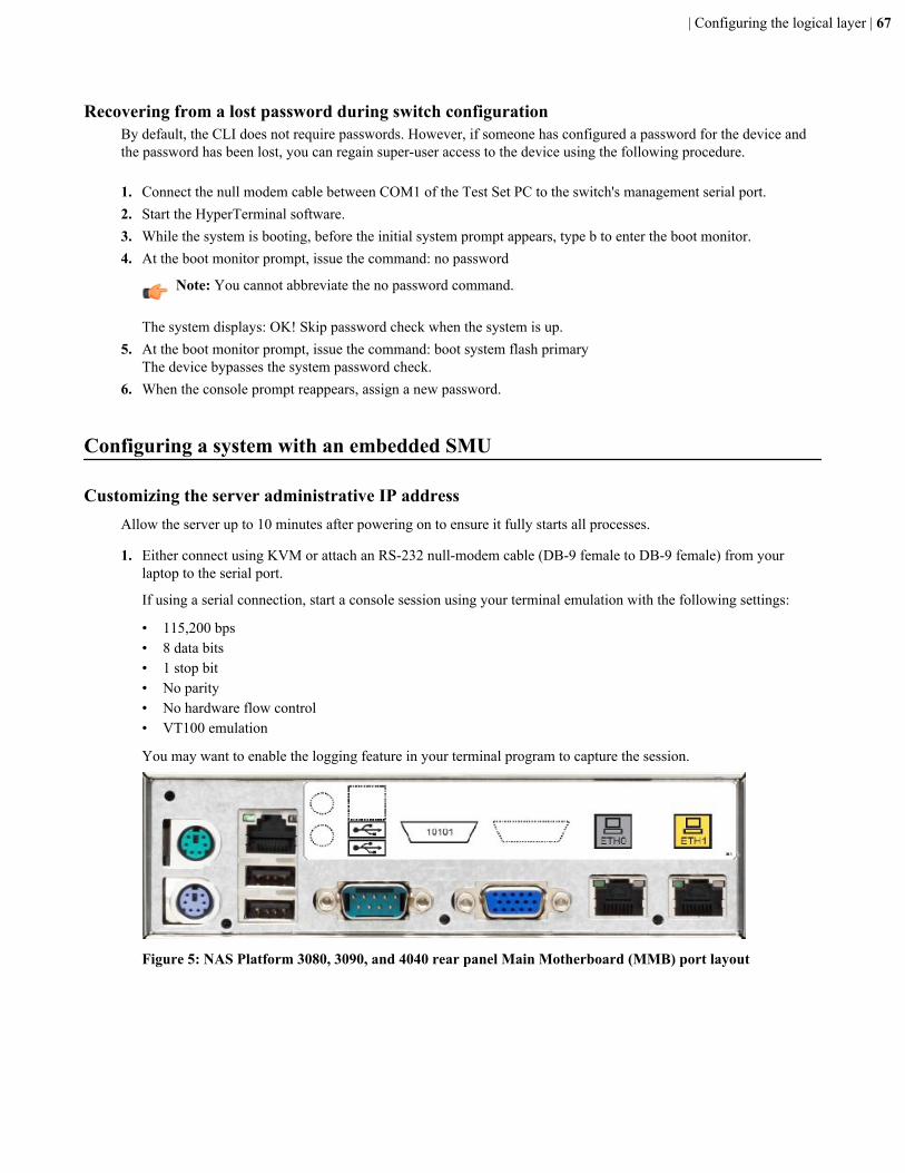
Recovering from a lost password during switch configurationBy default, the CLI does not require passwords. However, if someone has configured a password for the device andthe password has been lost, you can regain super-user access to the device using the following procedure.
1. Connect the null modem cable between COM1 of the Test Set PC to the switch's management serial port.2. Start the HyperTerminal software.3. While the system is booting, before the initial system prompt appears, type b to enter the boot monitor.4. At the boot monitor prompt, issue the command: no password
Note: You cannot abbreviate the no password command.
The system displays: OK! Skip password check when the system is up.5. At the boot monitor prompt, issue the command: boot system flash primary
The device bypasses the system password check.6. When the console prompt reappears, assign a new password.
Configuring a system with an embedded SMU
Customizing the server administrative IP addressAllow the server up to 10 minutes after powering on to ensure it fully starts all processes.
1. Either connect using KVM or attach an RS-232 null-modem cable (DB-9 female to DB-9 female) from yourlaptop to the serial port.
If using a serial connection, start a console session using your terminal emulation with the following settings:
• 115,200 bps• 8 data bits• 1 stop bit• No parity• No hardware flow control• VT100 emulation
You may want to enable the logging feature in your terminal program to capture the session.
Figure 5: NAS Platform 3080, 3090, and 4040 rear panel Main Motherboard (MMB) port layout
| Configuring the logical layer | 67
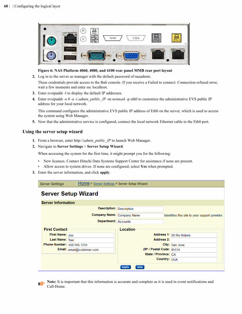
Figure 6: NAS Platform 4060, 4080, and 4100 rear panel MMB rear port layout2. Log in to the server as manager with the default password of nasadmin.
These credentials provide access to the Bali console. If you receive a Failed to connect: Connection refused error,wait a few moments and enter ssc localhost.
3. Enter evsipaddr -l to display the default IP addresses.4. Enter evsipaddr -e 0 -a -i admin_public_IP -m netmask -p eth0 to customize the administrative EVS public IP
address for your local network.
This command configures the administrative EVS public IP address of Eth0 on the server, which is used to accessthe system using Web Manager.
5. Now that the administrative service is configured, connect the local network Ethernet cable to the Eth0 port.
Using the server setup wizard
1. From a browser, enter http://admin_public_IP to launch Web Manager.2. Navigate to Server Settings > Server Setup Wizard.
When accessing the system for the first time, it might prompt you for the following:
• New licenses. Contact Hitachi Data Systems Support Center for assistance if none are present.• Allow access to system drives. If none are configured; select Yes when prompted.
3. Enter the server information, and click apply.
Note: It is important that this information is accurate and complete as it is used in event notifications andCall-Home.
68 | | Configuring the logical layer
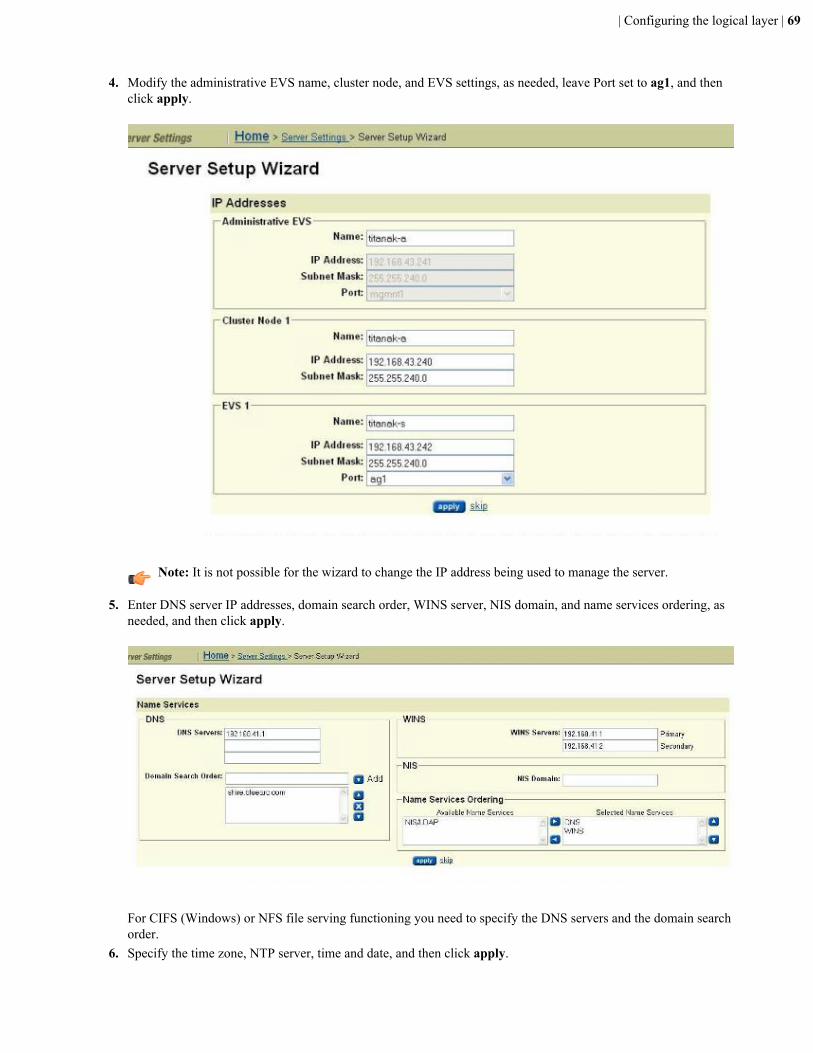
4. Modify the administrative EVS name, cluster node, and EVS settings, as needed, leave Port set to ag1, and thenclick apply.
Note: It is not possible for the wizard to change the IP address being used to manage the server.
5. Enter DNS server IP addresses, domain search order, WINS server, NIS domain, and name services ordering, asneeded, and then click apply.
For CIFS (Windows) or NFS file serving functioning you need to specify the DNS servers and the domain searchorder.
6. Specify the time zone, NTP server, time and date, and then click apply.
| Configuring the logical layer | 69
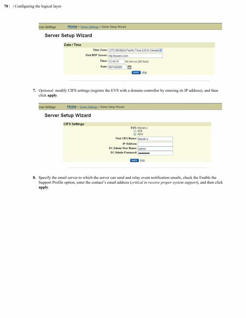
7. Optional: modify CIFS settings (register the EVS with a domain controller by entering its IP address), and then
click apply.
8. Specify the email server to which the server can send and relay event notification emails, check the Enable the
Support Profile option, enter the contact’s email address (critical to receive proper system support), and then clickapply.
70 | | Configuring the logical layer
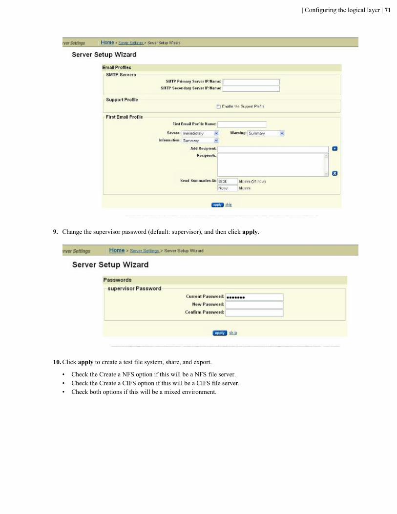
9. Change the supervisor password (default: supervisor), and then click apply.
10. Click apply to create a test file system, share, and export.
• Check the Create a NFS option if this will be a NFS file server.• Check the Create a CIFS option if this will be a CIFS file server.• Check both options if this will be a mixed environment.
| Configuring the logical layer | 71
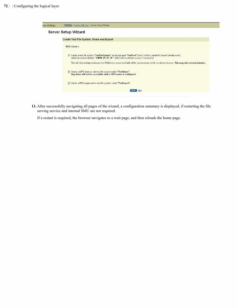
11. After successfully navigating all pages of the wizard, a configuration summary is displayed, if restarting the file
serving service and internal SMU are not required.
If a restart is required, the browser navigates to a wait page, and then reloads the home page.
72 | | Configuring the logical layer
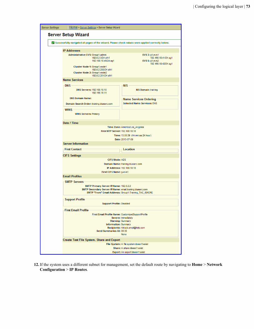
12. If the system uses a different subnet for management, set the default route by navigating to Home > Network
Configuration > IP Routes.
| Configuring the logical layer | 73
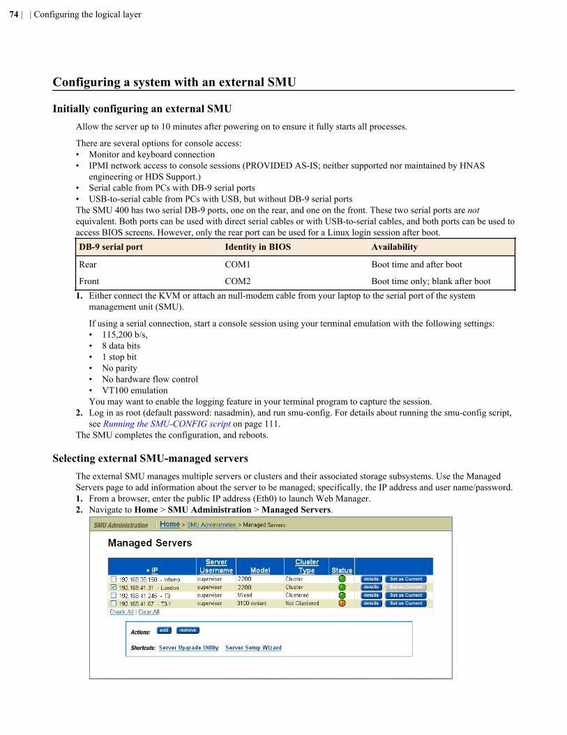
Configuring a system with an external SMU
Initially configuring an external SMUAllow the server up to 10 minutes after powering on to ensure it fully starts all processes.
There are several options for console access:• Monitor and keyboard connection• IPMI network access to console sessions (PROVIDED AS-IS; neither supported nor maintained by HNAS
engineering or HDS Support.)• Serial cable from PCs with DB-9 serial ports• USB-to-serial cable from PCs with USB, but without DB-9 serial portsThe SMU 400 has two serial DB-9 ports, one on the rear, and one on the front. These two serial ports are notequivalent. Both ports can be used with direct serial cables or with USB-to-serial cables, and both ports can be used toaccess BIOS screens. However, only the rear port can be used for a Linux login session after boot.DB-9 serial port Identity in BIOS Availability
Rear COM1 Boot time and after boot
Front COM2 Boot time only; blank after boot1. Either connect the KVM or attach an null-modem cable from your laptop to the serial port of the system
management unit (SMU).
If using a serial connection, start a console session using your terminal emulation with the following settings:• 115,200 b/s,• 8 data bits• 1 stop bit• No parity• No hardware flow control• VT100 emulationYou may want to enable the logging feature in your terminal program to capture the session.
2. Log in as root (default password: nasadmin), and run smu-config. For details about running the smu-config script,see Running the SMU-CONFIG script on page 111.
The SMU completes the configuration, and reboots.
Selecting external SMU-managed serversThe external SMU manages multiple servers or clusters and their associated storage subsystems. Use the ManagedServers page to add information about the server to be managed; specifically, the IP address and user name/password.1. From a browser, enter the public IP address (Eth0) to launch Web Manager.2. Navigate to Home > SMU Administration > Managed Servers.
74 | | Configuring the logical layer
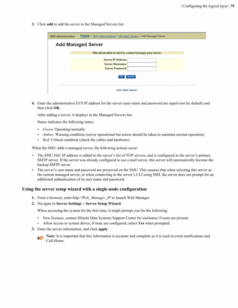
3. Click add to add the server to the Managed Servers list.
4. Enter the administrative EVS IP address for the server (user name and password are supervisor by default) and
then click OK.
After adding a server, it displays in the Managed Servers list.
Status indicates the following states:
• Green: Operating normally• Amber: Warning condition (server operational but action should be taken to maintain normal operation)• Red: Critical condition (check the cables and hardware)
When the SMU adds a managed server, the following actions occur:
• The SMU Eth1 IP address is added to the server’s list of NTP servers, and is configured as the server’s primarySMTP server. If the server was already configured to use a mail server, this server will automatically become thebackup SMTP server.
• The server’s user name and password are preserved on the SMU. This ensures that when selecting this server asthe current managed server, or when connecting to the server’s CLI using SSH, the server does not prompt for anadditional authentication of its user name and password.
Using the server setup wizard with a single-node configuration
1. From a browser, enter http://Web_Manager_IP to launch Web Manager.2. Navigate to Server Settings > Server Setup Wizard.
When accessing the system for the first time, it might prompt you for the following:
• New licenses, contact Hitachi Data Systems Support Center for assistance if none are present.• Allow access to system drives, if none are configured; select Yes when prompted.
3. Enter the server information, and click apply.
Note: It is important that this information is accurate and complete as it is used in event notifications andCall-Home.
| Configuring the logical layer | 75
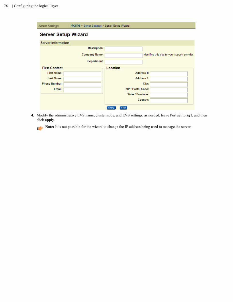
4. Modify the administrative EVS name, cluster node, and EVS settings, as needed, leave Port set to ag1, and thenclick apply.
Note: It is not possible for the wizard to change the IP address being used to manage the server.
76 | | Configuring the logical layer
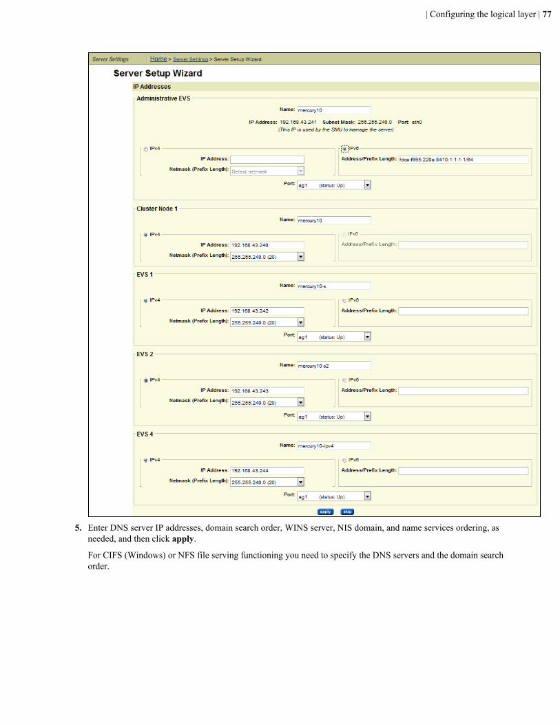
5. Enter DNS server IP addresses, domain search order, WINS server, NIS domain, and name services ordering, asneeded, and then click apply.
For CIFS (Windows) or NFS file serving functioning you need to specify the DNS servers and the domain searchorder.
| Configuring the logical layer | 77
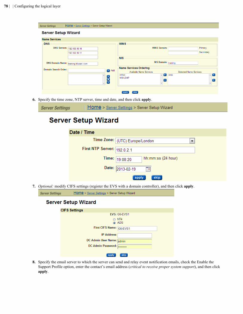
6. Specify the time zone, NTP server, time and date, and then click apply.
7. Optional: modify CIFS settings (register the EVS with a domain controller), and then click apply.
8. Specify the email server to which the server can send and relay event notification emails, check the Enable theSupport Profile option, enter the contact’s email address (critical to receive proper system support), and then clickapply.
78 | | Configuring the logical layer
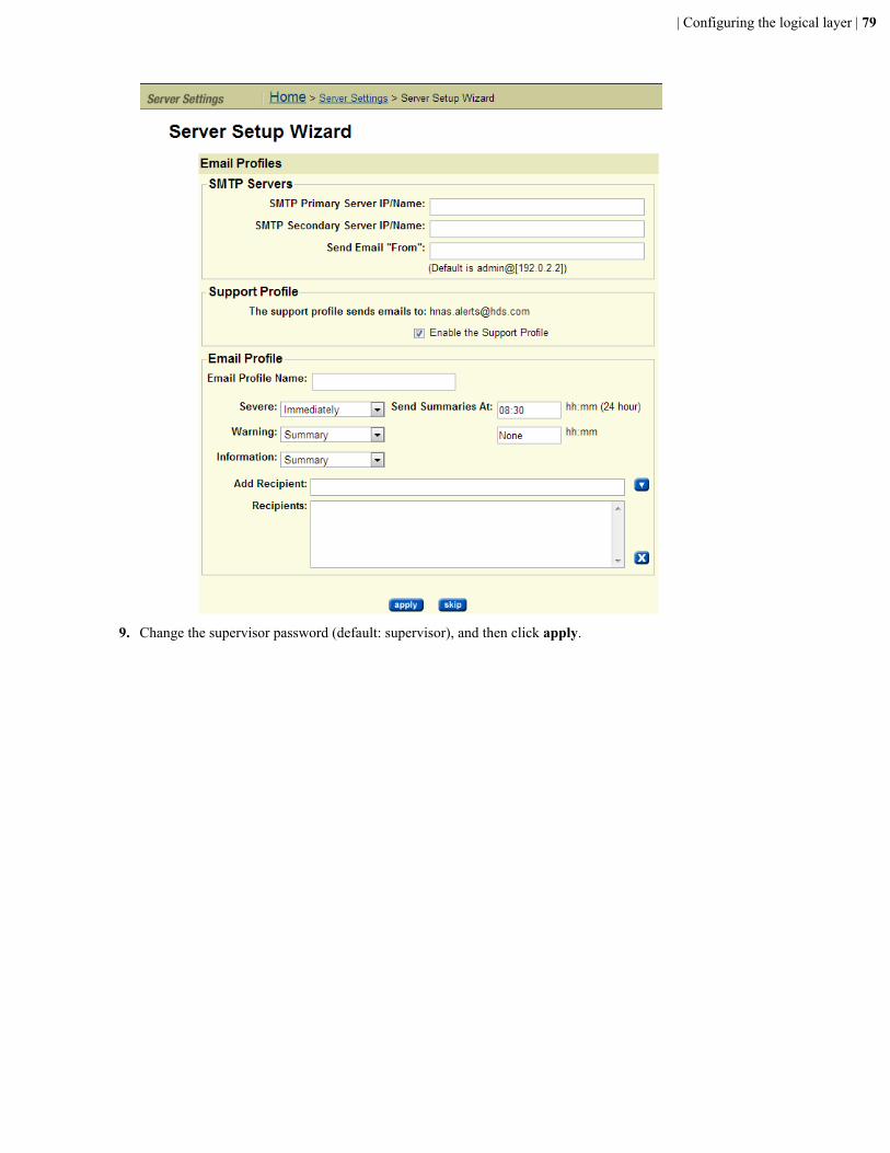
9. Change the supervisor password (default: supervisor), and then click apply.
| Configuring the logical layer | 79
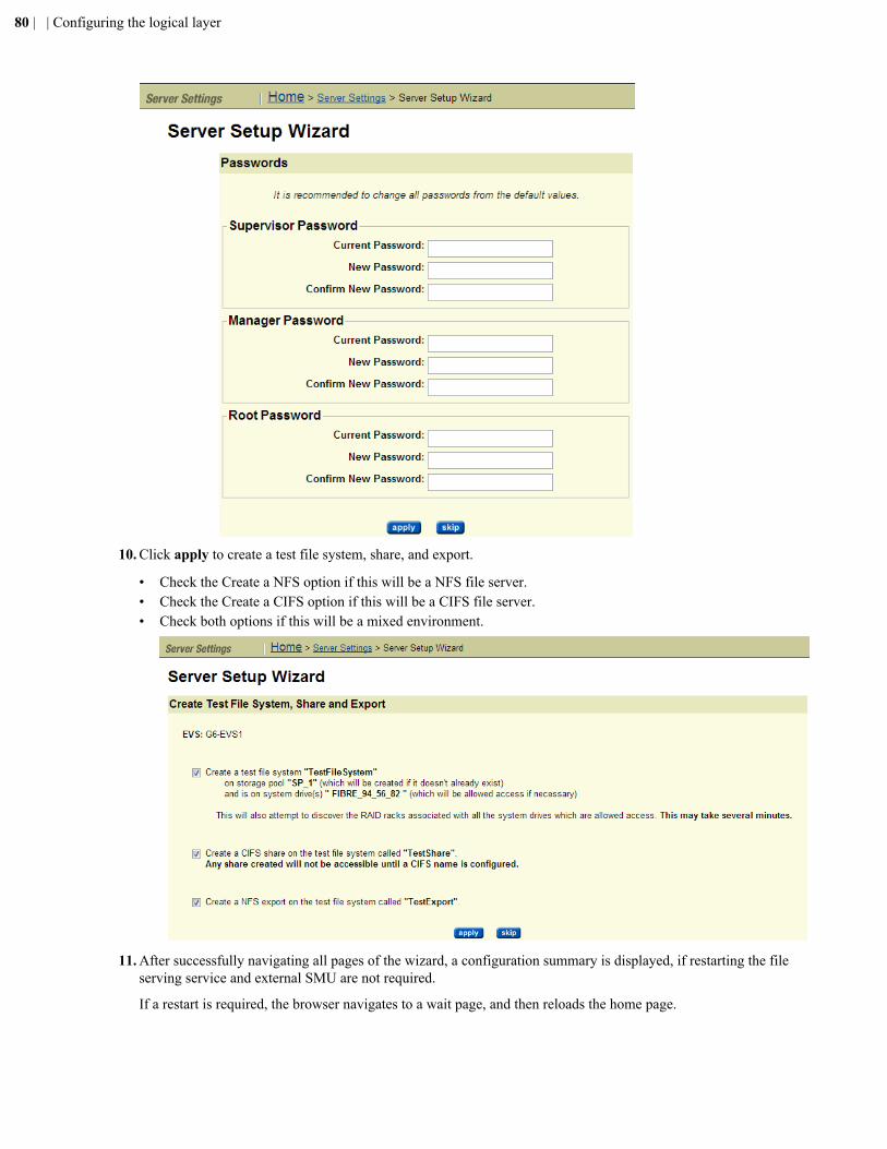
10. Click apply to create a test file system, share, and export.
• Check the Create a NFS option if this will be a NFS file server.• Check the Create a CIFS option if this will be a CIFS file server.• Check both options if this will be a mixed environment.
11. After successfully navigating all pages of the wizard, a configuration summary is displayed, if restarting the fileserving service and external SMU are not required.
If a restart is required, the browser navigates to a wait page, and then reloads the home page.
80 | | Configuring the logical layer
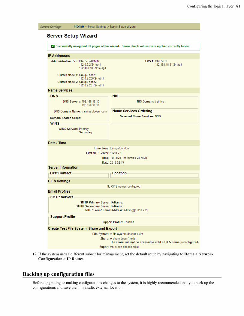
12. If the system uses a different subnet for management, set the default route by navigating to Home > NetworkConfiguration > IP Routes.
Backing up configuration filesBefore upgrading or making configurations changes to the system, it is highly recommended that you back up theconfigurations and save them in a safe, external location.
| Configuring the logical layer | 81
When using embedded SMU to backup configurations, the SMU configuration is included as a combined (server plusSMU) backup file. If an external SMU is used to manage the system, it is necessary to back up the server registry andSMU configuration independently, as they are archived separately.
Backing up the server registry
1. From a browser, enter http://Web_Manager_IP to launch Web Manager.2. Navigate to Home > Server Settings > Configuration Backup & Restore.3. Click backup.4. When prompted, save a copy of the registry to a safe location.
Backing up the external SMU configuration
1. Navigate to Home > SMU Administration > SMU Backup.2. Click Backup, choose a location (on your PC or workstation) to store/archive the configuration, and then click
OK. A copy of the backup is stored on the SMU.
Backing up the RAID controller configurationNote: Use this section for legacy non-HDS storage.
1. From a browser, enter http://Web_Manager_IP to launch Web Manager (for legacy BlueArc installations withNetApp or LSI storage).
2. Navigate to Home > Status & Monitoring > Diagnostic Downloads.3. In the Storage box, select the racks that are connected to the server being upgraded.
Only the Storage option needs to be checked. The other options may be unchecked; however, it is recommendedto download diagnostics from all system components prior to any upgrades.
If you do not see any racks listed, navigate to Home > Storage Management > RAID racks, and then clickDiscover Racks.
4. Click download, and when prompted, choose a location (on your PC or workstation) to store the configuration,and then click OK.
82 | | Configuring the logical layer
Chapter
4Accepting your system
Topics:
• Checkpoint• Additional system verification tests
The last phase ensures the customer is receiving system events to monitorongoing system health and establish external connectivity to Call-Homeservice. This step informs the Hitachi Data Systems Support Center andservice organization to begin monitoring and assure support entitlement isaccepted and activated.
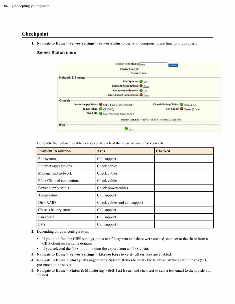
Checkpoint1. Navigate to Home > Server Settings > Server Status to verify all components are functioning properly.
Complete the following table as you verify each of the areas are installed correctly.
Problem Resolution Area Checked
File systems Call support
Ethernet aggregations Check cables
Management network Check cables
Fibre Channel connections Check cables
Power supply status Check power cables
Temperature Call support
Disk RAID Check cables and call support
Chassis battery status Call support
Fan speed Call support
EVS Call support
2. Depending on your configuration:
• If you modified the CIFS settings, and a test file system and share were created, connect to the share from aCIFS client on the same domain
• If you selected the NFS option, mount the export from an NFS client.3. Navigate to Home > Server Settings > License Keys to verify all services are enabled.4. Navigate to Home > Storage Management > System Drives to verify the health of all the system drives (SD)
presented to the server.5. Navigate to Home > Status & Monitoring > Self Test Event and click test to sent a test email to the profile you
created.
84 | | Accepting your system
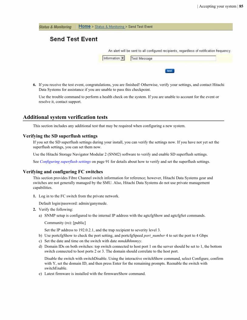
6. If you receive the test event, congratulations, you are finished! Otherwise, verify your settings, and contact Hitachi
Data Systems for assistance if you are unable to pass this checkpoint.
Use the trouble command to perform a health check on the system. If you are unable to account for the event orresolve it, contact support.
Additional system verification testsThis section includes any additional test that may be required when configuring a new system.
Verifying the SD superflush settingsIf you set the SD superflush settings during your install, you can verify the settings now. If you have not yet set thesuperflush settings, you can set them now.
Use the Hitachi Storage Navigator Modular 2 (SNM2) software to verify and enable SD superflush settings.
See Configuring superflush settings on page 91 for details about how to verify and set the superflush settings.
Verifying and configuring FC switchesThis section provides Fibre Channel switch information for reference; however, Hitachi Data Systems gear andswitches are not generally managed by the SMU. Also, Hitachi Data Systems do not use private managementcapabilities.
1. Log in to the FC switch from the private network.
Default login/password: admin/ganymede.2. Verify the following:
a) SNMP setup is configured to the internal IP address with the agtcfgShow and agtcfgSet commands.
Community (ro): [public]
Set the IP address to 192.0.2.1, and the trap recipient to severity level 3.b) Use portcfgShow to check the port setting, and portcfgSpeed port_number 4 to set the port to 4 Gbpsc) Set the date and time on the switch with date mmddhhmmyy.d) Domain IDs on both switches: top switch connected to host port 1 on the server should be set to 1, the bottom
switch connected to host ports 2 or 3. The domain should correlate to the host port.
Disable the switch with switchDisable. Using the interactive switchShow command, select Configure, confirmwith Y, set the domain ID, and then press Enter for the remaining prompts. Reenable the switch withswitchEnable.
e) Latest firmware is installed with the firmwareShow command.
| Accepting your system | 85

Appendix
AUpgrading storage firmware
Topics:
• Upgrading storage array firmware
Upgrade the firmware on the storage arrays to take advantage of the changesin the newest version.
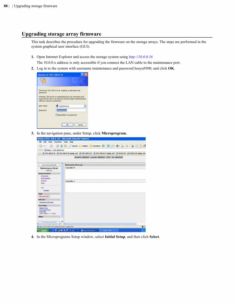
Upgrading storage array firmwareThis task describes the procedure for upgrading the firmware on the storage arrays. The steps are performed in thesystem graphical user interface (GUI).
1. Open Internet Explorer and access the storage system using http://10.0.0.16The 10.0.0.x address is only accessible if you connect the LAN cable to the maintenance port.
2. Log in to the system with username maintenance and password hosyu9500, and click OK.
3. In the navigation pane, under Setup, click Microprogram.
4. In the Microprograms Setup window, select Initial Setup, and then click Select.
88 | | Upgrading storage firmware
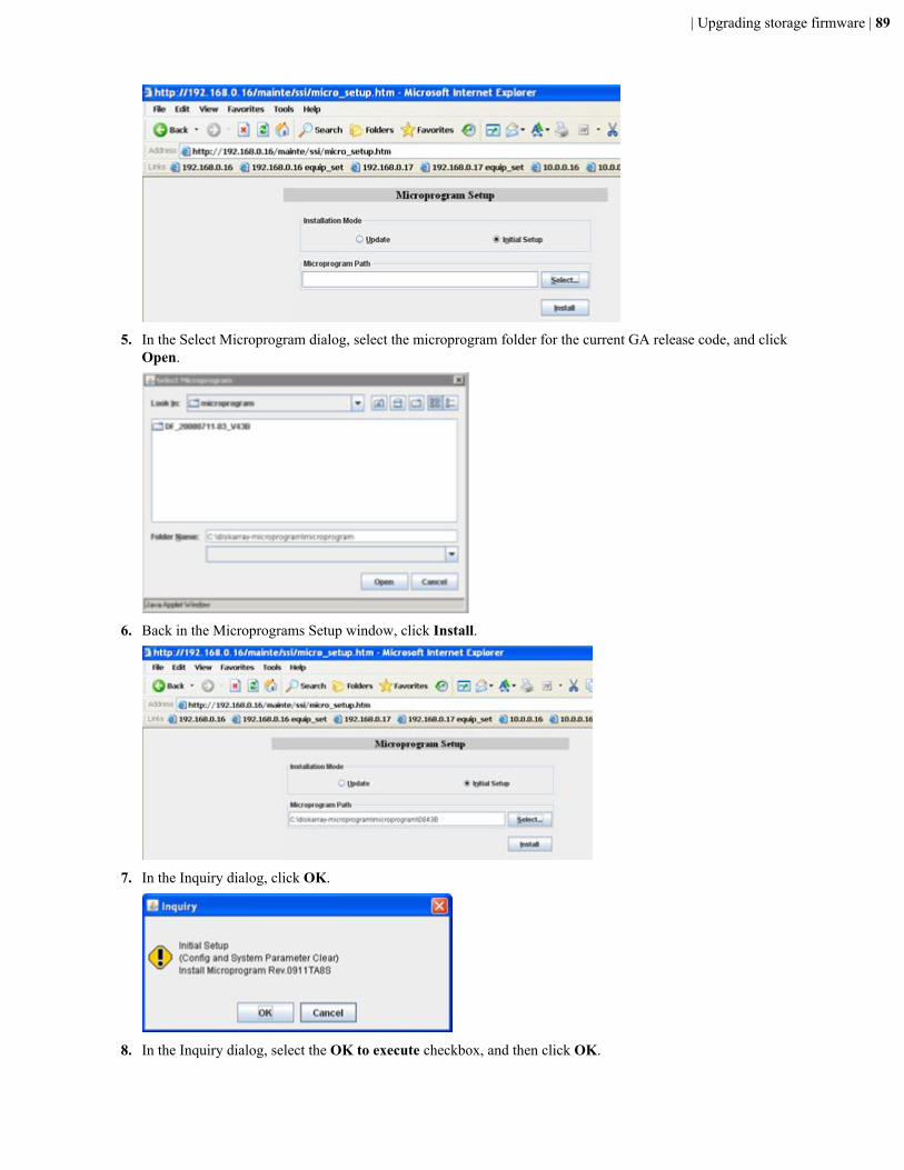
5. In the Select Microprogram dialog, select the microprogram folder for the current GA release code, and clickOpen.
6. Back in the Microprograms Setup window, click Install.
7. In the Inquiry dialog, click OK.
8. In the Inquiry dialog, select the OK to execute checkbox, and then click OK.
| Upgrading storage firmware | 89
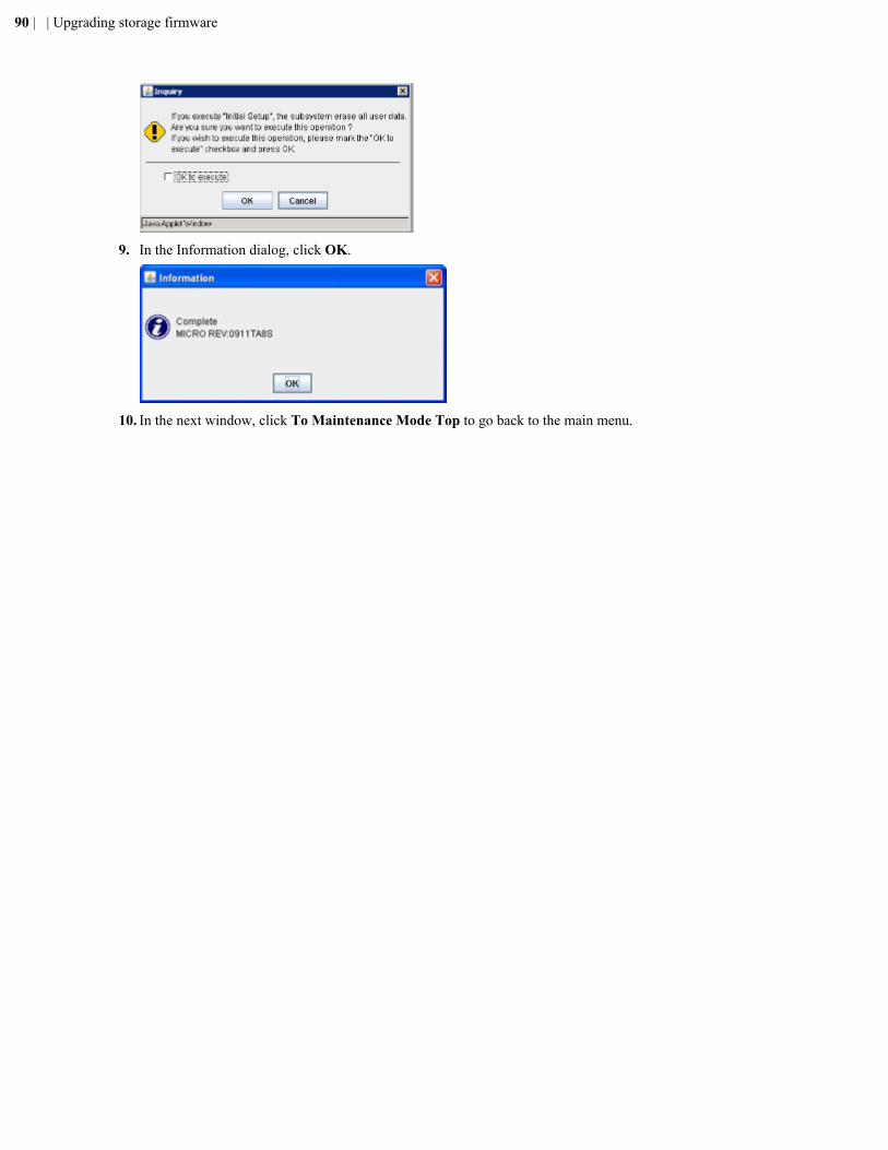
9. In the Information dialog, click OK.
10. In the next window, click To Maintenance Mode Top to go back to the main menu.
90 | | Upgrading storage firmware
Appendix
BConfiguring superflush settings
Topics:
• Configuring the superflush settings
The superflush feature gives you the ability to force the write cache to hold afull stripe update, so you can turn random writes into a streaming write.Configure the superflush settings to maximize the workload of the storagearray.

Configuring the superflush settingsAfter you have created the volumes on the storage, you must configure the settings for the superflush capabilities.
1. Determine how each RAID set on the storage array's system disk (SD) has been set up, including the number ofmembers in the array, and the stripe depth (segment size).
2. Use the SSH command in the system management unit (SMU) CLI, and select the managing server.3. To list the existing superflush setting, issue the command: sd-list -p
merc6-clus-1:$ sd-list -p Device Stat Allow Cap/GB Mirror In span S'flush ------ ---- ----- ------ ------- ---------------- -------- 0 OK Yes 837 Pri sas_sp ...... 1 OK Yes 837 Pri sas_sp ...... 2 OK Yes 2793 Pri nlsas_sp ...... 3 OK Yes 2793 Pri nlsas_sp ...... 4 OK Yes 2793 Pri nlsas_sp ......
The dots in the S’flush column indicate that superflush is disabled.4. To manually set the superflush, perform the following steps:
1. Issue the command: sd-set2. To form your command, use the values that displayed when you verified the volume group layouts of the
system. For the purposes of this example, they are 4+1 with a stripe depth of 64K. You then issue thecommand: sd-set -w 4 -s 64 0-4
To display the new settings, issue the command: sd-list -pmerc6-clus-1:$ sd-list -p Device Stat Allow Cap/GB Mirror In span S'flush ------ ---- ----- ------ ------- ---------------- -------- 0 OK Yes 837 Pri sas_sp 3x64K 1 OK Yes 837 Pri sas_sp 3x64K 2 OK Yes 2793 Pri nlsas_sp 3x64K 3 OK Yes 2793 Pri nlsas_sp 3x64K 4 OK Yes 2793 Pri nlsas_sp 3x64K
Superflush is now enabled and the new superflush values display in the S’flush column.
92 | | Configuring superflush settings
Appendix
CUpgrading HNAS or HUS File Module server software
Topics:
• Upgrading operating systems• Upgrading server firmware
This section covers procedures for how you upgrade the operating system(OS) and firmware on a server. The procedures apply to both the Hitachi NASPlatform server and the Hitachi Unified Storage File Module server.
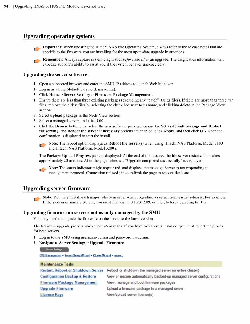
Upgrading operating systems
Important: When updating the Hitachi NAS File Operating System, always refer to the release notes that arespecific to the firmware you are installing for the most up-to-date upgrade instructions.
Remember: Always capture system diagnostics before and after an upgrade. The diagnostics information willexpedite support’s ability to assist you if the system behaves unexpectedly.
Upgrading the server software
1. Open a supported browser and enter the SMU IP address to launch Web Manager.2. Log in as admin (default password: nasadmin).3. Click Home > Server Settings > Firmware Package Management.4. Ensure there are less than three existing packages (excluding any “patch” .tar.gz files). If there are more than three .tar
files, remove the oldest files by selecting the check box next to its name, and clicking delete in the Package Viewsection.
5. Select upload package in the Node View section.6. Select a managed server, and click OK.7. Click the Browse button, and select the new software package; ensure the Set as default package and Restart
file serving, and Reboot the server if necessary options are enabled, click Apply, and then click OK when theconfirmation is displayed to start the install.
Note: The reboot option displays as Reboot the server(s) when using Hitachi NAS Platform, Model 3100and Hitachi NAS Platform, Model 3200 s.
The Package Upload Progress page is displayed. At the end of the process, the file server restarts. This takesapproximately 20 minutes. After the page refreshes, “Upgrade completed successfully” is displayed.
Note: The status indicator might appear red, and displays the message Server is not responding tomanagement protocol. Connection refused.; if so, refresh the page to resolve the issue.
Upgrading server firmwareNote: You must install each major release in order when upgrading a system from earlier releases. For example:If the system is running SU 7.x, you must first install 8.1.2312.09, or later, before upgrading to 10.x.
Upgrading firmware on servers not usually managed by the SMUYou may need to upgrade the firmware on the server to the latest version.
The firmware upgrade process takes about 45 minutes. If you have two servers installed, you must repeat the processfor both servers.1. Log in to the SMU using username admin and password nasadmin.2. Navigate to Server Settings > Upgrade Firmware.
94 | | Upgrading HNAS or HUS File Module server software
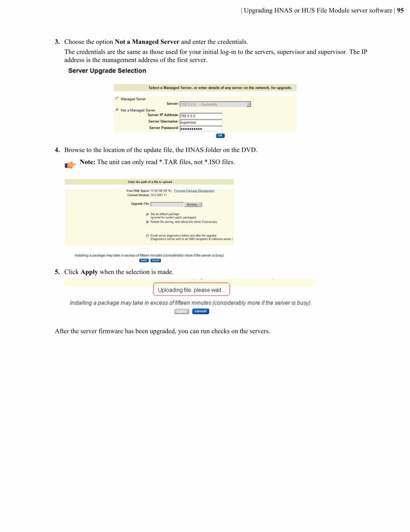
3. Choose the option Not a Managed Server and enter the credentials.The credentials are the same as those used for your initial log-in to the servers, supervisor and supervisor. The IPaddress is the management address of the first server.
4. Browse to the location of the update file, the HNAS folder on the DVD.
Note: The unit can only read *.TAR files, not *.ISO files.
5. Click Apply when the selection is made.
After the server firmware has been upgraded, you can run checks on the servers.
| Upgrading HNAS or HUS File Module server software | 95

Appendix
DRunning the NAS-PRECONFIG script
Topics:
• Running the NAS-PRECONFIGscript
Use the nas-preconfig script to automate the execution of common commandsrequired for server configuration.
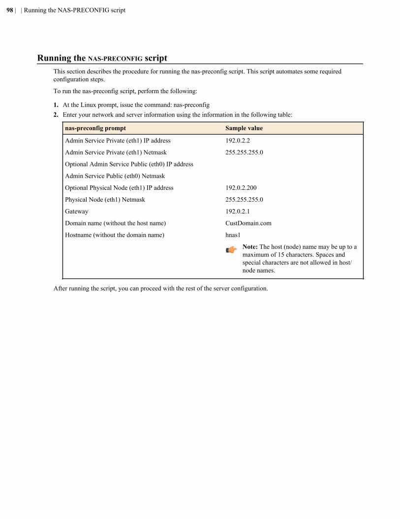
Running the NAS-PRECONFIG scriptThis section describes the procedure for running the nas-preconfig script. This script automates some requiredconfiguration steps.
To run the nas-preconfig script, perform the following:
1. At the Linux prompt, issue the command: nas-preconfig2. Enter your network and server information using the information in the following table:
nas-preconfig prompt Sample value
Admin Service Private (eth1) IP address 192.0.2.2
Admin Service Private (eth1) Netmask 255.255.255.0
Optional Admin Service Public (eth0) IP address
Admin Service Public (eth0) Netmask
Optional Physical Node (eth1) IP address 192.0.2.200
Physical Node (eth1) Netmask 255.255.255.0
Gateway 192.0.2.1
Domain name (without the host name) CustDomain.com
Hostname (without the domain name) hnas1
Note: The host (node) name may be up to amaximum of 15 characters. Spaces andspecial characters are not allowed in host/node names.
After running the script, you can proceed with the rest of the server configuration.
98 | | Running the NAS-PRECONFIG script
Appendix
EUsing a virtual SMU
Topics:
• Using a virtual SMU• Installation requirements• Installing SMU software in a VM• Upgrading the OS for a virtual
SMU• Configuring vSwitches• Deploying CentOS SMU VMs• Installing SMU software in a VM• Configuring VM resource
allocations• Installing VMware tools
This section describes virtual SMUs and covers procedures for how youinstall, upgrade, and configure the software.
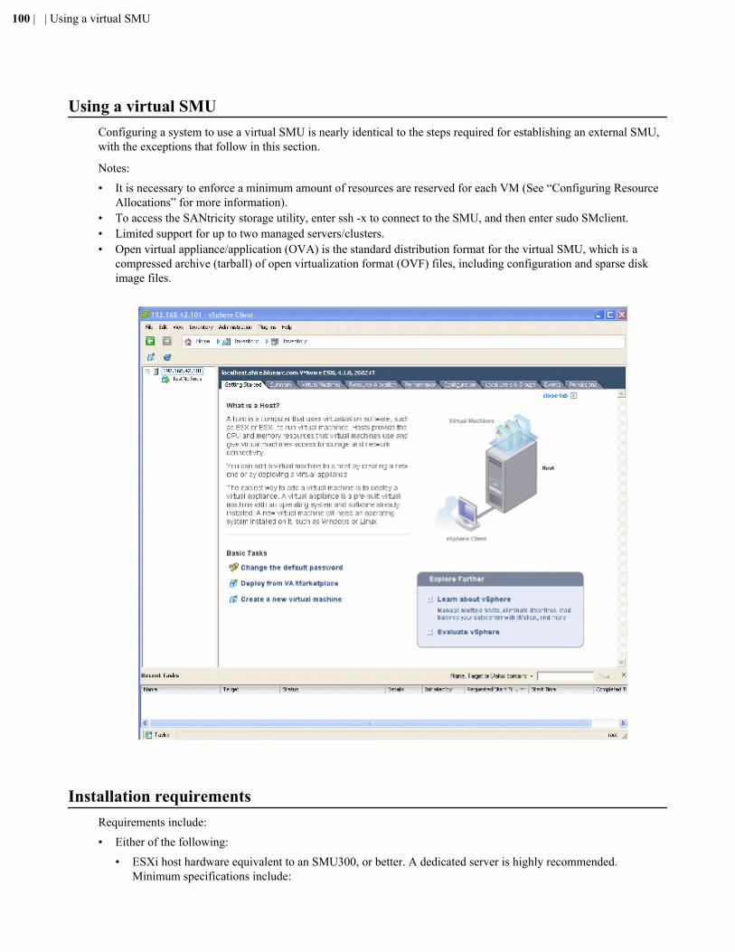
Using a virtual SMUConfiguring a system to use a virtual SMU is nearly identical to the steps required for establishing an external SMU,with the exceptions that follow in this section.
Notes:
• It is necessary to enforce a minimum amount of resources are reserved for each VM (See “Configuring ResourceAllocations” for more information).
• To access the SANtricity storage utility, enter ssh -x to connect to the SMU, and then enter sudo SMclient.• Limited support for up to two managed servers/clusters.• Open virtual appliance/application (OVA) is the standard distribution format for the virtual SMU, which is a
compressed archive (tarball) of open virtualization format (OVF) files, including configuration and sparse diskimage files.
Installation requirementsRequirements include:
• Either of the following:
• ESXi host hardware equivalent to an SMU300, or better. A dedicated server is highly recommended.Minimum specifications include:
100 | | Using a virtual SMU
• 64-bit CPU with dual 2-GHz cores
• 4GB RAM
• 500 GB hard drive space
• Two network adapters, one dedicated to the SMU private network
• DVD drive• VMware enterprise-class software, installed and operational.
Refer to the documentation provided with your VMware solution for details, as the subject is beyond the scopeof this document.
• IP addresses required:
• ESXi hardware• Virtual SMU administration
Each VM you deploy requires one IP address for management.• ESXi installation CD• Configured OVA package• SMU install image on CD
Note: If you have any questions, please contact your Support organization for assistance with these procedures.
Installing SMU software in a VM1. Deploy the CentOS SMU VMs.2. Configure the vSwitches.3. Configure the VM resource allocations.4. Install the SMU software in a VM.
a) Insert the media into the DVD drive.b) Right-click the virtual machine (VM), and select Edit Settings.c) Select the CD/DVD drive.
| Using a virtual SMU | 101
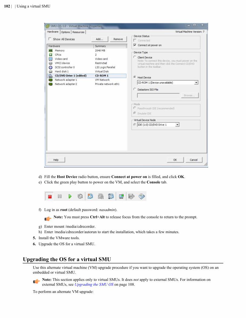
d) Fill the Host Device radio button, ensure Connect at power on is filled, and click OK.e) Click the green play button to power on the VM, and select the Console tab.
f) Log in as root (default password: nasadmin).
Note: You must press Ctrl+Alt to release focus from the console to return to the prompt.
g) Enter mount /media/cdrecorder.h) Enter /media/cdrecorder/autorun to start the installation, which takes a few minutes.
5. Install the VMware tools.6. Upgrade the OS for a virtual SMU.
Upgrading the OS for a virtual SMUUse this alternate virtual machine (VM) upgrade procedure if you want to upgrade the operating system (OS) on anembedded or virtual SMU.
Note: This section applies only to virtual SMUs. It does not apply to external SMUs. For information onexternal SMUs, see Upgrading the SMU OS on page 108.
To perform an alternate VM upgrade:
102 | | Using a virtual SMU
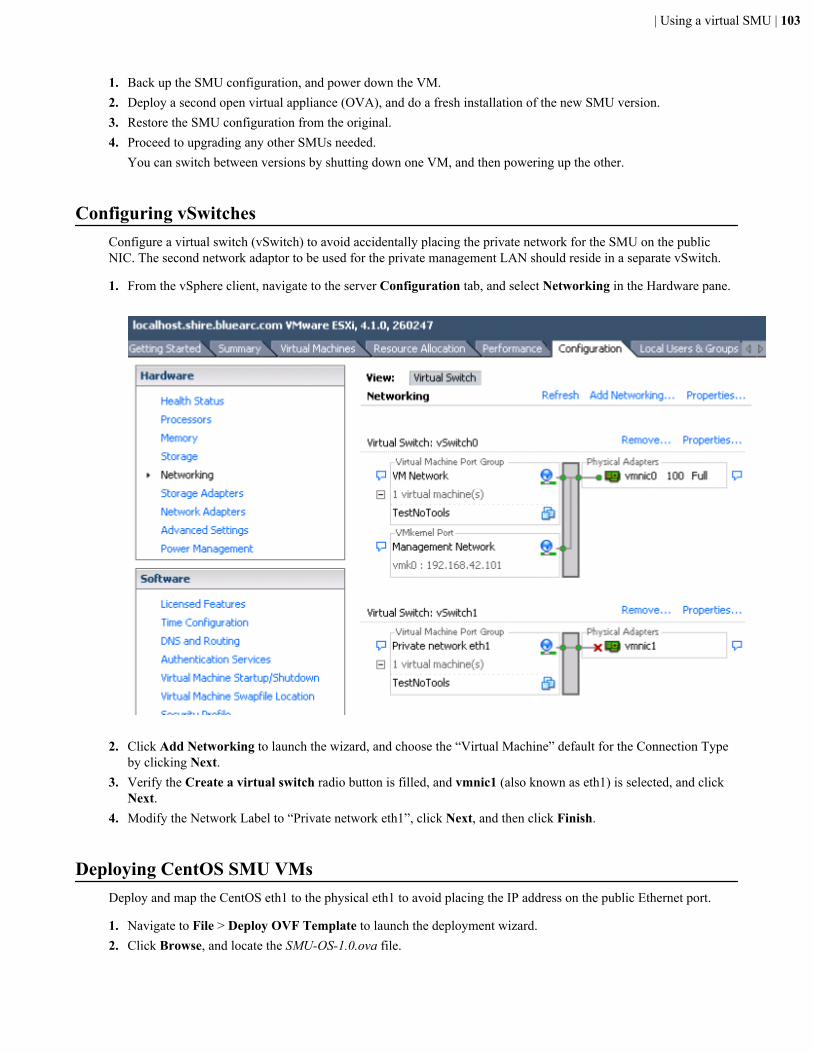
1. Back up the SMU configuration, and power down the VM.2. Deploy a second open virtual appliance (OVA), and do a fresh installation of the new SMU version.3. Restore the SMU configuration from the original.4. Proceed to upgrading any other SMUs needed.
You can switch between versions by shutting down one VM, and then powering up the other.
Configuring vSwitchesConfigure a virtual switch (vSwitch) to avoid accidentally placing the private network for the SMU on the publicNIC. The second network adaptor to be used for the private management LAN should reside in a separate vSwitch.
1. From the vSphere client, navigate to the server Configuration tab, and select Networking in the Hardware pane.
2. Click Add Networking to launch the wizard, and choose the “Virtual Machine” default for the Connection Type
by clicking Next.3. Verify the Create a virtual switch radio button is filled, and vmnic1 (also known as eth1) is selected, and click
Next.4. Modify the Network Label to “Private network eth1”, click Next, and then click Finish.
Deploying CentOS SMU VMsDeploy and map the CentOS eth1 to the physical eth1 to avoid placing the IP address on the public Ethernet port.
1. Navigate to File > Deploy OVF Template to launch the deployment wizard.2. Click Browse, and locate the SMU-OS-1.0.ova file.
| Using a virtual SMU | 103
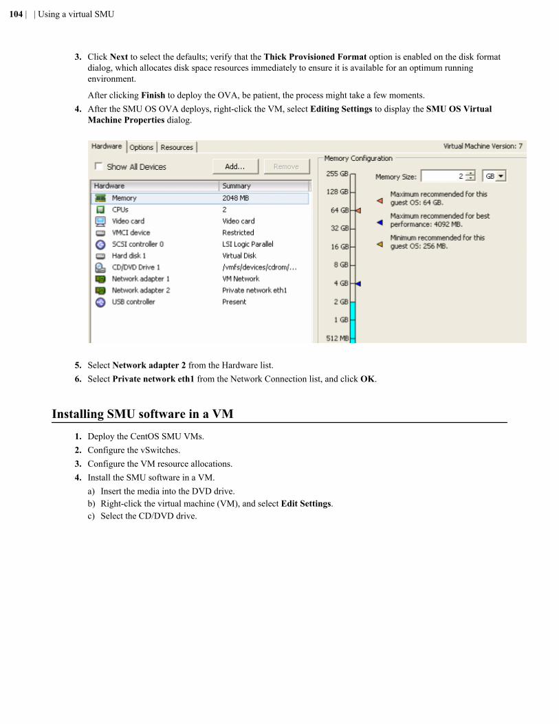
3. Click Next to select the defaults; verify that the Thick Provisioned Format option is enabled on the disk formatdialog, which allocates disk space resources immediately to ensure it is available for an optimum runningenvironment.
After clicking Finish to deploy the OVA, be patient, the process might take a few moments.4. After the SMU OS OVA deploys, right-click the VM, select Editing Settings to display the SMU OS Virtual
Machine Properties dialog.
5. Select Network adapter 2 from the Hardware list.6. Select Private network eth1 from the Network Connection list, and click OK.
Installing SMU software in a VM1. Deploy the CentOS SMU VMs.2. Configure the vSwitches.3. Configure the VM resource allocations.4. Install the SMU software in a VM.
a) Insert the media into the DVD drive.b) Right-click the virtual machine (VM), and select Edit Settings.c) Select the CD/DVD drive.
104 | | Using a virtual SMU
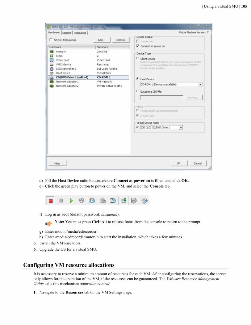
d) Fill the Host Device radio button, ensure Connect at power on is filled, and click OK.e) Click the green play button to power on the VM, and select the Console tab.
f) Log in as root (default password: nasadmin).
Note: You must press Ctrl+Alt to release focus from the console to return to the prompt.
g) Enter mount /media/cdrecorder.h) Enter /media/cdrecorder/autorun to start the installation, which takes a few minutes.
5. Install the VMware tools.6. Upgrade the OS for a virtual SMU.
Configuring VM resource allocationsIt is necessary to reserve a minimum amount of resources for each VM. After configuring the reservations, the serveronly allows for the operation of the VM, if the resources can be guaranteed. The VMware Resource ManagementGuide calls this mechanism admission control.
1. Navigate to the Resources tab on the VM Settings page.
| Using a virtual SMU | 105
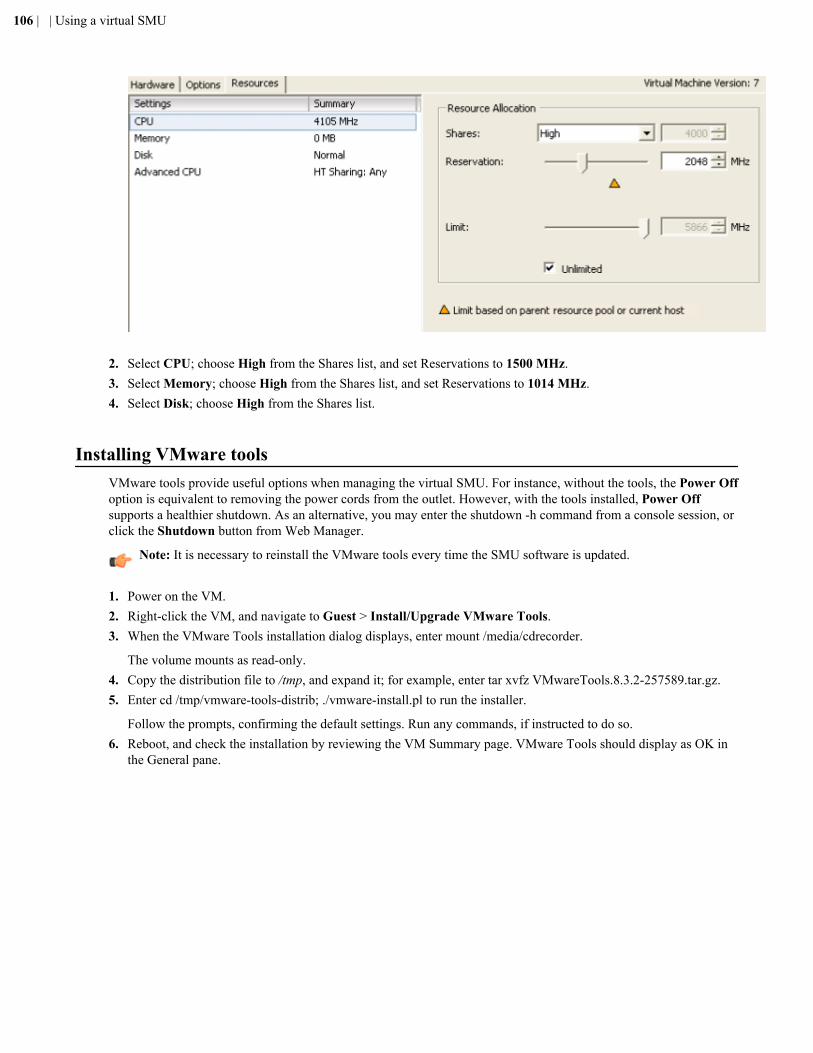
2. Select CPU; choose High from the Shares list, and set Reservations to 1500 MHz.3. Select Memory; choose High from the Shares list, and set Reservations to 1014 MHz.4. Select Disk; choose High from the Shares list.
Installing VMware toolsVMware tools provide useful options when managing the virtual SMU. For instance, without the tools, the Power Offoption is equivalent to removing the power cords from the outlet. However, with the tools installed, Power Offsupports a healthier shutdown. As an alternative, you may enter the shutdown -h command from a console session, orclick the Shutdown button from Web Manager.
Note: It is necessary to reinstall the VMware tools every time the SMU software is updated.
1. Power on the VM.2. Right-click the VM, and navigate to Guest > Install/Upgrade VMware Tools.3. When the VMware Tools installation dialog displays, enter mount /media/cdrecorder.
The volume mounts as read-only.4. Copy the distribution file to /tmp, and expand it; for example, enter tar xvfz VMwareTools.8.3.2-257589.tar.gz.5. Enter cd /tmp/vmware-tools-distrib; ./vmware-install.pl to run the installer.
Follow the prompts, confirming the default settings. Run any commands, if instructed to do so.6. Reboot, and check the installation by reviewing the VM Summary page. VMware Tools should display as OK in
the General pane.
106 | | Using a virtual SMU
Appendix
FUpgrading an external SMU
Topics:
• About upgrading an external SMU• Upgrading the SMU OS• Upgrading the SMU software
This section covers procedures for how you upgrade the operating system(OS) and system management unit (SMU) software for an external SMU.
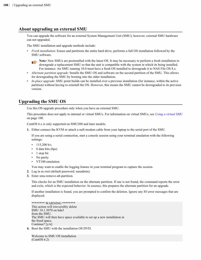
About upgrading an external SMUYou can upgrade the software for an external System Management Unit (SMU); however, external SMU hardwarecan not upgraded.
The SMU installation and upgrade methods include:• Fresh installation: Erases and partitions the entire hard drive; performs a full OS installation followed by the
SMU software.
Note: New SMUs are preinstalled with the latest OS. It may be necessary to perform a fresh installation todowngrade a replacement SMU so that the unit is compatible with the system in which its being installed.For instance: An SMU running 10.0 must have a fresh OS installed to downgrade it to NAS File OS 8.x.
• Alternate partition upgrade: Installs the SMU OS and software on the second partition of the SMU. This allowsfor downgrading the SMU by booting into the older installation.
• In-place upgrade: SMU point builds can be installed over a previous installation (for instance, within the activepartition) without having to reinstall the OS. However, this means the SMU cannot be downgraded to its previousversion.
Upgrading the SMU OSUse this OS upgrade procedure only when you have an external SMU.
This procedure does not apply to internal or virtual SMUs. For information on virtual SMUs, see Using a virtual SMUon page 100.
CentOS 6.x is only supported on SMU200 and later models.
1. Either connect the KVM or attach a null-modem cable from your laptop to the serial port of the SMU.
If you are using a serial connection, start a console session using your terminal emulation with the followingsettings:• 115,200 b/s• 8 data bits (bps)• 1 stop bit• No parity• VT100 emulationYou may want to enable the logging feature in your terminal program to capture the session.
2. Log in as root (default password: nasadmin).3. Enter smu-remove-alt-partition.
This checks for an SMU installation on the alternate partition. If one is not found, the command reports the errorand exits, which is the expected behavior. In essence, this prepares the alternate partition for an upgrade.
If another installation is found, you are prompted to confirm the deletion. Ignore any IO error messages that aredisplayed.
******** WARNING ********This action will irreversibly deleteSMU 10.1.3070 on hda3from the SMU.The SMU will then have space available to set up a new installation inthe freed space.Continue? [y/n]
4. Boot the SMU with the installation OS DVD.
Welcome to SMU OS Installation(CentOS 6.2)
108 | | Upgrading an external SMU
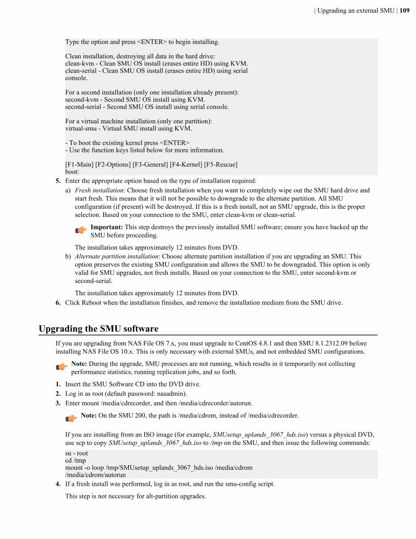
Type the option and press <ENTER> to begin installing.
Clean installation, destroying all data in the hard drive:clean-kvm - Clean SMU OS install (erases entire HD) using KVM.clean-serial - Clean SMU OS install (erases entire HD) using serialconsole.
For a second installation (only one installation already present):second-kvm - Second SMU OS install using KVM.second-serial - Second SMU OS install using serial console.
For a virtual machine installation (only one partition):virtual-smu - Virtual SMU install using KVM. - To boot the existing kernel press <ENTER>- Use the function keys listed below for more information.
[F1-Main] [F2-Options] [F3-General] [F4-Kernel] [F5-Rescue]boot:
5. Enter the appropriate option based on the type of installation required:a) Fresh installation: Choose fresh installation when you want to completely wipe out the SMU hard drive and
start fresh. This means that it will not be possible to downgrade to the alternate partition. All SMUconfiguration (if present) will be destroyed. If this is a fresh install, not an SMU upgrade, this is the properselection. Based on your connection to the SMU, enter clean-kvm or clean-serial.
Important: This step destroys the previously installed SMU software; ensure you have backed up theSMU before proceeding.
The installation takes approximately 12 minutes from DVD.b) Alternate partition installation: Choose alternate partition installation if you are upgrading an SMU. This
option preserves the existing SMU configuration and allows the SMU to be downgraded. This option is onlyvalid for SMU upgrades, not fresh installs. Based on your connection to the SMU, enter second-kvm orsecond-serial.
The installation takes approximately 12 minutes from DVD.6. Click Reboot when the installation finishes, and remove the installation medium from the SMU drive.
Upgrading the SMU softwareIf you are upgrading from NAS File OS 7.x, you must upgrade to CentOS 4.8.1 and then SMU 8.1.2312.09 beforeinstalling NAS File OS 10.x. This is only necessary with external SMUs, and not embedded SMU configurations.
Note: During the upgrade, SMU processes are not running, which results in it temporarily not collectingperformance statistics, running replication jobs, and so forth.
1. Insert the SMU Software CD into the DVD drive.2. Log in as root (default password: nasadmin).3. Enter mount /media/cdrecorder, and then /media/cdrecorder/autorun.
Note: On the SMU 200, the path is /media/cdrom, instead of /media/cdrecorder.
If you are installing from an ISO image (for example, SMUsetup_uplands_3067_hds.iso) versus a physical DVD,use scp to copy SMUsetup_uplands_3067_hds.iso to /tmp on the SMU, and then issue the following commands:su - rootcd /tmpmount -o loop /tmp/SMUsetup_uplands_3067_hds.iso /media/cdrom/media/cdrom/autorun
4. If a fresh install was performed, log in as root, and run the smu-config script.
This step is not necessary for alt-partition upgrades.
| Upgrading an external SMU | 109

For details about running the smu-config script, see Running the SMU-CONFIG script on page 111.After the SMU has restarted, the SMU software upgrade is complete.
5. If a fresh install was performed, restore the SMU configuration from your most recent backup file.This step is not necessary for alt-partition upgrades.The SMU reboots.
110 | | Upgrading an external SMU
Appendix
GRunning the SMU-CONFIG script
Topics:
• Running the SMU-CONFIG script
Use the smu-config script to automate the execution of common commandsrequired for system management unit (SMU) configuration.
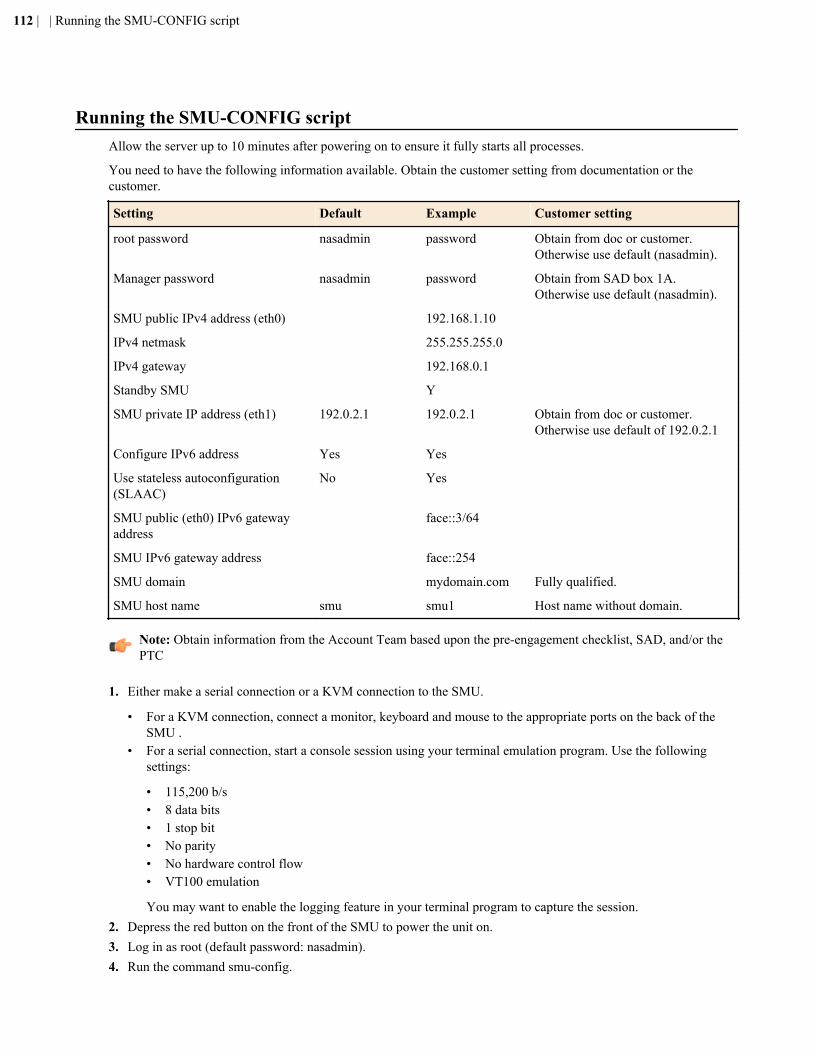
Running the SMU-CONFIG scriptAllow the server up to 10 minutes after powering on to ensure it fully starts all processes.
You need to have the following information available. Obtain the customer setting from documentation or thecustomer.
Setting Default Example Customer setting
root password nasadmin password Obtain from doc or customer.Otherwise use default (nasadmin).
Manager password nasadmin password Obtain from SAD box 1A.Otherwise use default (nasadmin).
SMU public IPv4 address (eth0) 192.168.1.10
IPv4 netmask 255.255.255.0
IPv4 gateway 192.168.0.1
Standby SMU Y
SMU private IP address (eth1) 192.0.2.1 192.0.2.1 Obtain from doc or customer.Otherwise use default of 192.0.2.1
Configure IPv6 address Yes Yes
Use stateless autoconfiguration(SLAAC)
No Yes
SMU public (eth0) IPv6 gatewayaddress
face::3/64
SMU IPv6 gateway address face::254
SMU domain mydomain.com Fully qualified.
SMU host name smu smu1 Host name without domain.
Note: Obtain information from the Account Team based upon the pre-engagement checklist, SAD, and/or thePTC
1. Either make a serial connection or a KVM connection to the SMU.
• For a KVM connection, connect a monitor, keyboard and mouse to the appropriate ports on the back of theSMU .
• For a serial connection, start a console session using your terminal emulation program. Use the followingsettings:
• 115,200 b/s• 8 data bits• 1 stop bit• No parity• No hardware control flow• VT100 emulation
You may want to enable the logging feature in your terminal program to capture the session.2. Depress the red button on the front of the SMU to power the unit on.3. Log in as root (default password: nasadmin).4. Run the command smu-config.
112 | | Running the SMU-CONFIG script
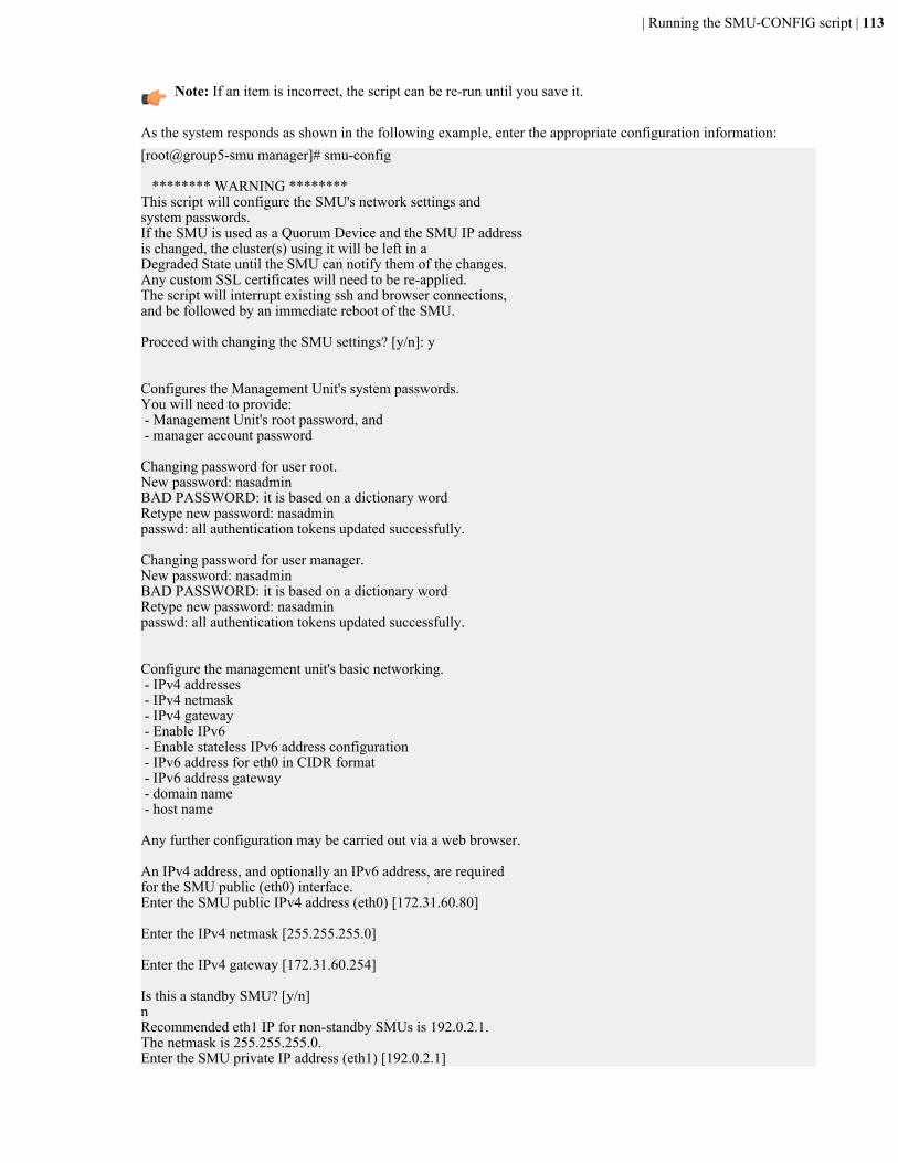
Note: If an item is incorrect, the script can be re-run until you save it.
As the system responds as shown in the following example, enter the appropriate configuration information:[root@group5-smu manager]# smu-config
******** WARNING ********This script will configure the SMU's network settings and system passwords.If the SMU is used as a Quorum Device and the SMU IP addressis changed, the cluster(s) using it will be left in a Degraded State until the SMU can notify them of the changes.Any custom SSL certificates will need to be re-applied.The script will interrupt existing ssh and browser connections,and be followed by an immediate reboot of the SMU.
Proceed with changing the SMU settings? [y/n]: y
Configures the Management Unit's system passwords.You will need to provide: - Management Unit's root password, and - manager account password
Changing password for user root.New password: nasadminBAD PASSWORD: it is based on a dictionary wordRetype new password: nasadminpasswd: all authentication tokens updated successfully.
Changing password for user manager.New password: nasadminBAD PASSWORD: it is based on a dictionary wordRetype new password: nasadminpasswd: all authentication tokens updated successfully.
Configure the management unit's basic networking. - IPv4 addresses - IPv4 netmask - IPv4 gateway - Enable IPv6 - Enable stateless IPv6 address configuration - IPv6 address for eth0 in CIDR format - IPv6 address gateway - domain name - host name
Any further configuration may be carried out via a web browser.
An IPv4 address, and optionally an IPv6 address, are required for the SMU public (eth0) interface.Enter the SMU public IPv4 address (eth0) [172.31.60.80]
Enter the IPv4 netmask [255.255.255.0]
Enter the IPv4 gateway [172.31.60.254]
Is this a standby SMU? [y/n]nRecommended eth1 IP for non-standby SMUs is 192.0.2.1.The netmask is 255.255.255.0.Enter the SMU private IP address (eth1) [192.0.2.1]
| Running the SMU-CONFIG script | 113

Configure IPv6 address? [y/n] [yes]yUse stateless autoconfiguration (SLAAC)? [y/n] [yes]yEnter the SMU public (eth0) IPv6 address. Use CIDR formator "none" [face::3/64]
Enter the SMU IPv6 gateway address or "none". [face::254]
Enter the Domain name for the management unit (without the host name) [mydomain.com]
Enter the Host name for the management unit (without the domain name) [smu]
SMU public IP (eth0) = 172.31.60.80 Netmask = 255.255.255.0 Gateway = 172.31.60.254 SMU private IPv4 (eth1) = 192.0.2.1 Enable IPv6 = yes IPv6 stateless auto-configuration = yes SMU static IPv6 (eth0) = face::3/64 SMU static IPv6 gateway = face::254 Domain = mydomain.com Unit hostname = smuAre the above settings correct? [y/n] y
The SMU will reboot after you save the configuration.
114 | | Running the SMU-CONFIG script
Appendix
HAdding nodes to an N-way cluster (three-plus nodes)
Topics:
• Maximum number of nodessupported
• Adding nodes to an N-way cluster• Cluster cable configurations
The system design allows you to create an N-way cluster. An N-way cluster isa cluster that contains three or more nodes. You can create an N-way clusteror upgrade a two-node cluster to an N-way cluster. This section also includesthe configuration of the 10 GbE cluster interconnect switches that are used toconnect the nodes.
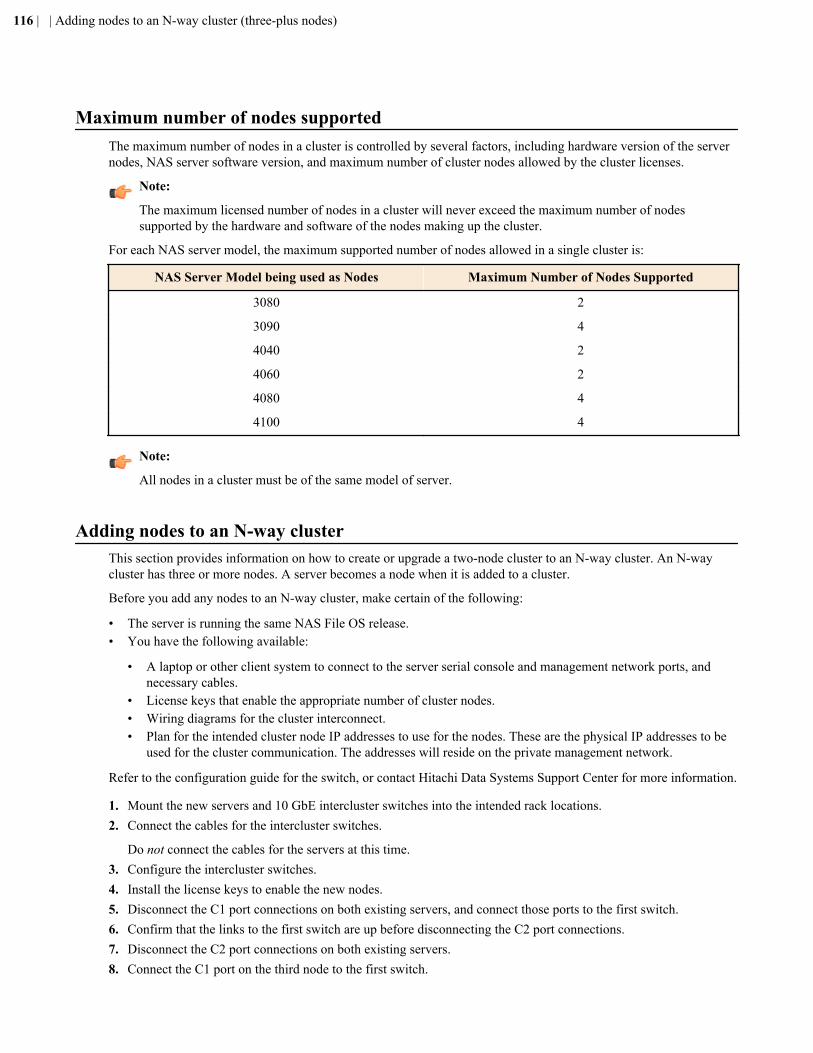
Maximum number of nodes supportedThe maximum number of nodes in a cluster is controlled by several factors, including hardware version of the servernodes, NAS server software version, and maximum number of cluster nodes allowed by the cluster licenses.
Note:
The maximum licensed number of nodes in a cluster will never exceed the maximum number of nodessupported by the hardware and software of the nodes making up the cluster.
For each NAS server model, the maximum supported number of nodes allowed in a single cluster is:
NAS Server Model being used as Nodes Maximum Number of Nodes Supported
3080 2
3090 4
4040 2
4060 2
4080 4
4100 4
Note:
All nodes in a cluster must be of the same model of server.
Adding nodes to an N-way clusterThis section provides information on how to create or upgrade a two-node cluster to an N-way cluster. An N-waycluster has three or more nodes. A server becomes a node when it is added to a cluster.
Before you add any nodes to an N-way cluster, make certain of the following:
• The server is running the same NAS File OS release.• You have the following available:
• A laptop or other client system to connect to the server serial console and management network ports, andnecessary cables.
• License keys that enable the appropriate number of cluster nodes.• Wiring diagrams for the cluster interconnect.• Plan for the intended cluster node IP addresses to use for the nodes. These are the physical IP addresses to be
used for the cluster communication. The addresses will reside on the private management network.
Refer to the configuration guide for the switch, or contact Hitachi Data Systems Support Center for more information.
1. Mount the new servers and 10 GbE intercluster switches into the intended rack locations.2. Connect the cables for the intercluster switches.
Do not connect the cables for the servers at this time.3. Configure the intercluster switches.4. Install the license keys to enable the new nodes.5. Disconnect the C1 port connections on both existing servers, and connect those ports to the first switch.6. Confirm that the links to the first switch are up before disconnecting the C2 port connections.7. Disconnect the C2 port connections on both existing servers.8. Connect the C1 port on the third node to the first switch.
116 | | Adding nodes to an N-way cluster (three-plus nodes)
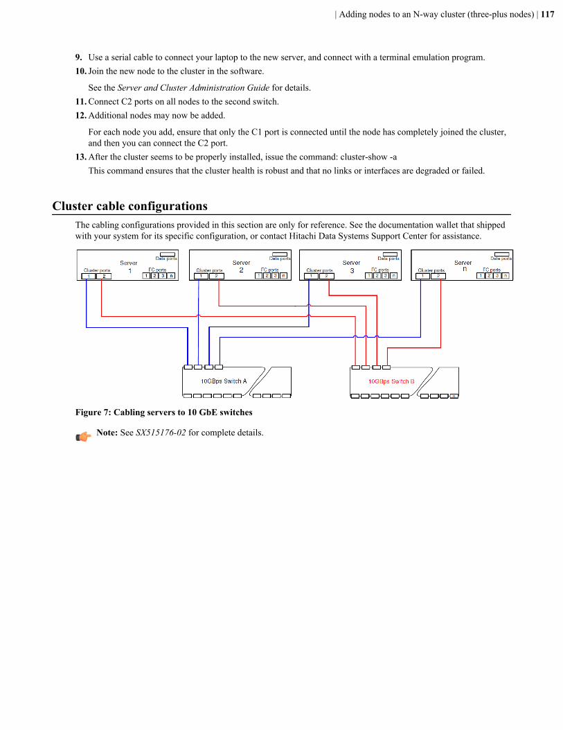
9. Use a serial cable to connect your laptop to the new server, and connect with a terminal emulation program.10. Join the new node to the cluster in the software.
See the Server and Cluster Administration Guide for details.11. Connect C2 ports on all nodes to the second switch.12. Additional nodes may now be added.
For each node you add, ensure that only the C1 port is connected until the node has completely joined the cluster,and then you can connect the C2 port.
13. After the cluster seems to be properly installed, issue the command: cluster-show -aThis command ensures that the cluster health is robust and that no links or interfaces are degraded or failed.
Cluster cable configurationsThe cabling configurations provided in this section are only for reference. See the documentation wallet that shippedwith your system for its specific configuration, or contact Hitachi Data Systems Support Center for assistance.
Figure 7: Cabling servers to 10 GbE switches
Note: See SX515176-02 for complete details.
| Adding nodes to an N-way cluster (three-plus nodes) | 117

System Installation Guide
MK-92HNAS015-05
Hitachi Data Systems
Corporate Headquarters2845 Lafayette StreetSanta Clara, California 95050-2639U.S.A.www.hds.com
Regional Contact Information
Americas+1 408 970 [email protected]
Europe, Middle East, and Africa+44 (0)1753 [email protected]
Asia Pacific+852 3189 [email protected]