Embed Size (px)
Citation preview

History, Science and Technology of the Sound Surveillance System (SOSUS)
By Michael Flicker
1

Early History
• In 1944 Ewing and Worzel successfully tested a theory that low-frequency sound should be able to travel long distances in the deep ocean. A ship dropped 4-pound deep explosive charges in the ocean and they were heard at distances up to 900 miles.
• The U.S. Navy soon realized that low-frequency sound could be used to increase the range at which submarines could be detected.
2
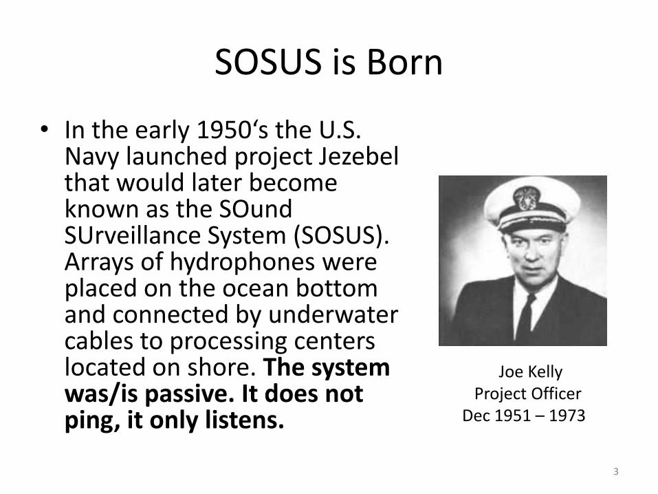
SOSUS is Born
• In the early 1950‘s the U.S. Navy launched project Jezebel that would later become known as the SOund SUrveillance System (SOSUS). Arrays of hydrophones were placed on the ocean bottom and connected by underwater cables to processing centers located on shore. The system was/is passive. It does not ping, it only listens.
3
Joe KellyProject Officer
Dec 1951 – 1973

Fixed System Concept
4

Early SOSUS
5
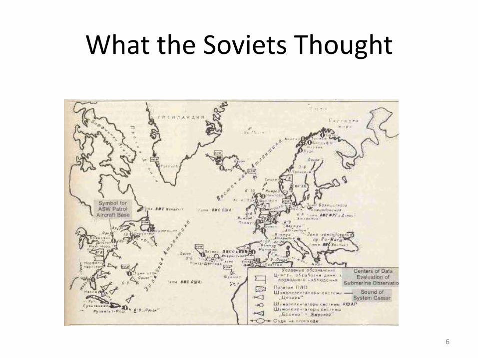
What the Soviets Thought
6
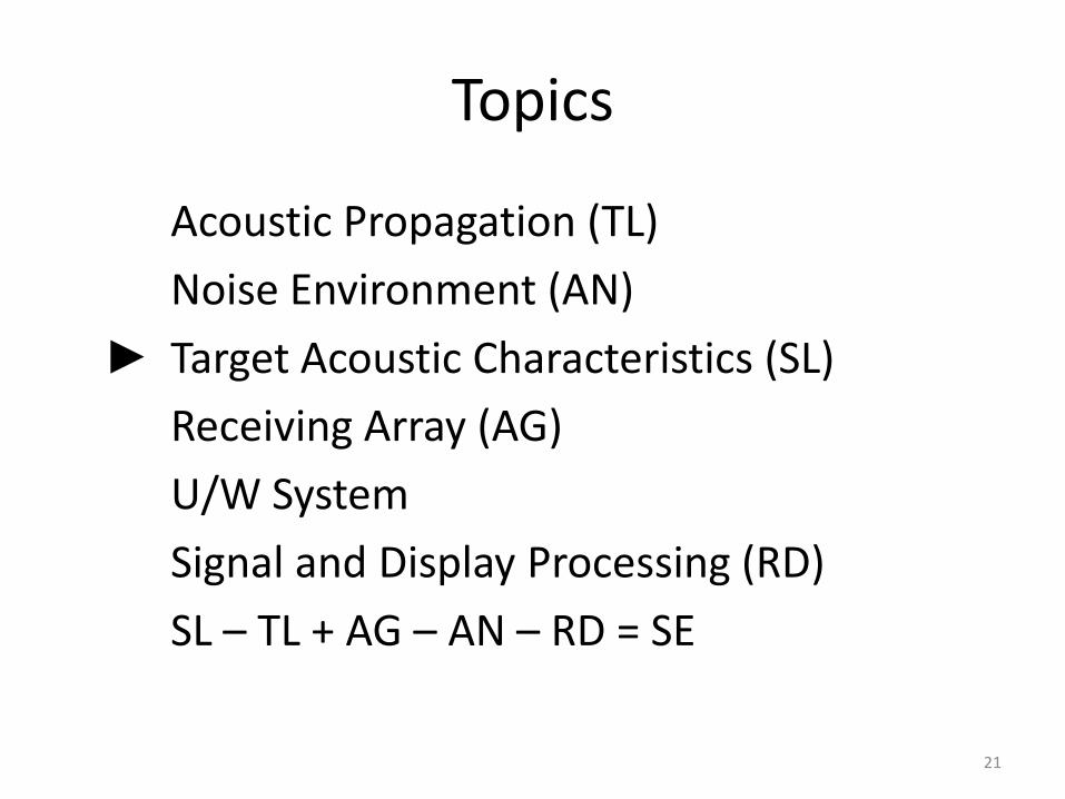
Topics
► Acoustic Propagation (TL)
Noise Environment (AN)
Target Acoustic Characteristics (SL)
Receiving Array (AG)
U/W System
Signal and Display Processing (RD)
SL – TL + AG – AN – RD = SE
7
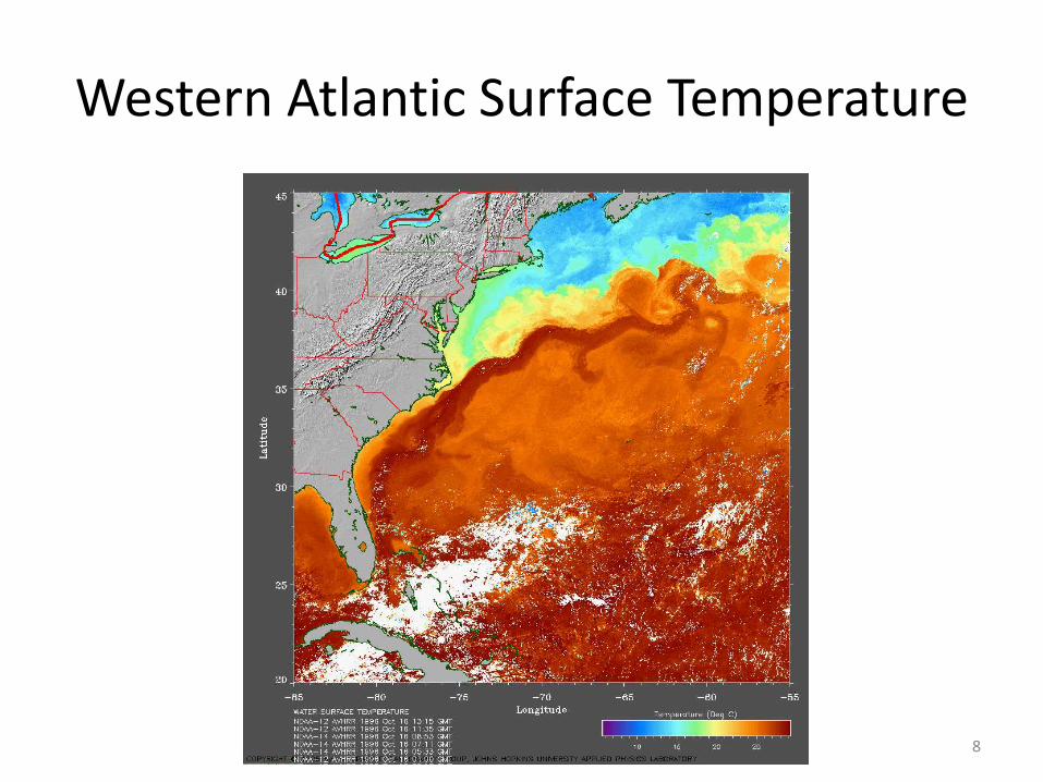
Western Atlantic Surface Temperature
8

Physics of Propagation
9
-6000
-5000
-4000
-3000
-2000
-1000
0
0 10 20 30
Wat
er
De
pth
(m
)
Temperature (deg C)
Ocean Temperature (34°N, 63°W)
Feb
Aug
-6000
-5000
-4000
-3000
-2000
-1000
0
1480 1500 1520 1540 1560
Oce
an D
ep
th (
m)
Sound Speed (m/s)
Sound Speed Profile (34°N,63°W)
Feb
Aug
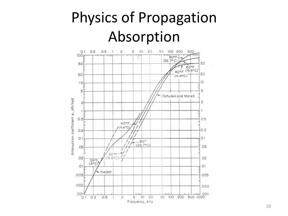
Physics of PropagationAbsorption
10

Transmission loss for August
Range (km)
Dep
th (
m)
Transmission Loss (dB re 1m), August
0 100 200 300 400 500
0
1000
2000
3000
4000
5000
6000
30
40
50
60
70
80
90
100
110
120
Receiver at 4000 m
11
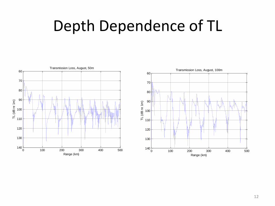
Depth Dependence of TL
0 100 200 300 400 500
60
70
80
90
100
110
120
130
140
TL (
dB
re
1m
)
Range (km)
Transmission Loss, August, 100m
0 100 200 300 400 500
60
70
80
90
100
110
120
130
140
TL (
dB
re
1m
)
Range (km)
Transmission Loss, August, 50m
12

Western Atlantic Bathymetry
13
Target Acoustic Characteristics
Topics
Acoustic Propagation (TL)
► Noise Environment (AN)
Target Acoustic Characteristics (SL)
Receiving Array (AG)
U/W System
Signal and Display Processing (RD)
SL – TL + AG – AN – RD = SE
14
Noise in Ocean
• Ambient ocean noise is the acoustic background noise in the ocean from all sources
• It is of interest in itself not just because of the impact it has on sonar, but because of the impact it has on marine life.
15
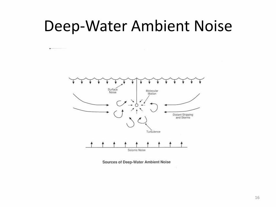
Deep-Water Ambient Noise
16

Ship Radiated Noise
• Predominant sources of surface ship noise are the propeller and the machinery required for propulsion and power generation. The machinery noise and other structure-borne sources of noise radiate into the water through the hull of the ship, noise from the propeller is generated in the water, and flow noise is generated on the ship-water boundary.
17

Radiated Noise M/V Overseas Harriette
18
16 kts
8 kts
175 m cargo ship poweredby a direct-drive low speed diesel engine.
Radiated noise data show high level tonal frequenciesfrom the generator , main engine firing rate and blade rate harmonics due topropeller cavitation .

Ship Radiated Noise
19
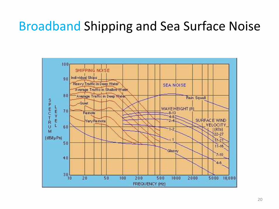
Broadband Shipping and Sea Surface Noise
20
Topics
Acoustic Propagation (TL)
Noise Environment (AN)
► Target Acoustic Characteristics (SL)
Receiving Array (AG)
U/W System
Signal and Display Processing (RD)
SL – TL + AG – AN – RD = SE
21

Estimates of the Source Level of Diesel Submarines
• 1, 2 - World War II submarines at 10 and 6 knots respectively [Urick, 1983]
• 3 - Russian submarine design 641, source level at 50 Hz, speed of 2 knots [Lebed’ko, 1994]
• 4 - German Type 209, estimated source level of discrete components of spectrum at speed of 8 knots [Gorbachev, 1994]
• 5 - Modern diesel submarines of Third World Countries [Mit’ko, 1994]
• 6 - Russian submarine design 887, source level at 50 Hz [Lebed’ko, 1994]
Caution: This data was taken from the internet. The fact that it is shown here does not make it correct.
The Office of Naval Intelligence provides SL data to the Surveillance community
22

Topics
Acoustic Propagation (TL)
Noise Environment (AN)
Target Acoustic Characteristics (SL)
► Receiving Array (AG)
U/W System
Signal and Display Processing (RD)
SL – TL + AG – AN – RD = SE
23
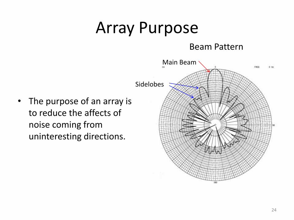
Array Purpose
• The purpose of an array is to reduce the affects of noise coming from uninteresting directions.
24
Beam Pattern
Main Beam
Sidelobes

Advanced Radar Surveillance System
• Antenna: 60 cm x 40 cm
• Frequency(f) ~ 9 GHz
• C = 3x1010 cm/sec
• Wavelength(λ ) = C/f λ = 3x10¹⁰ / 9x109 = 3.3 cm
• Beam width(o) ~ 60 λ/size
• Beam width ~ 60x3.3/60
• Beam width ~ 3.3o
25
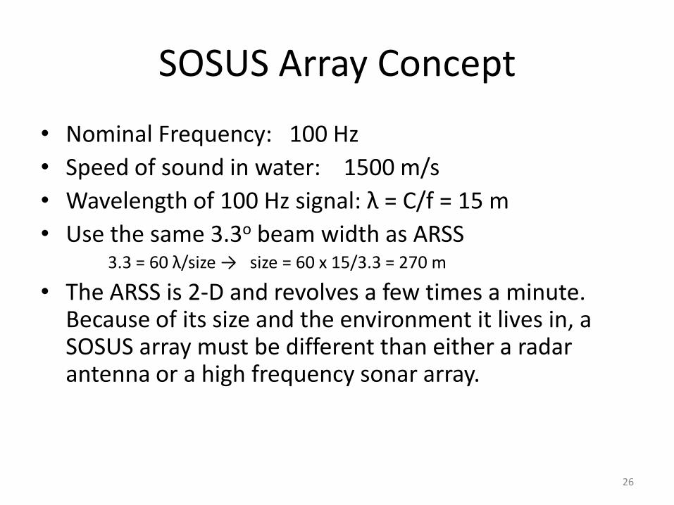
SOSUS Array Concept
• Nominal Frequency: 100 Hz
• Speed of sound in water: 1500 m/s
• Wavelength of 100 Hz signal: λ = C/f = 15 m
• Use the same 3.3o beam width as ARSS3.3 = 60 λ/size → size = 60 x 15/3.3 = 270 m
• The ARSS is 2-D and revolves a few times a minute. Because of its size and the environment it lives in, a SOSUS array must be different than either a radar antenna or a high frequency sonar array.
26

SOSUS Array Concept - 2
27
A SOSUS array is collection of hydrophones arranged in a straight line. Hydrophone SIGNALS are independently brought to shore. Since the array cannot be rotated to look in all directions a processing concept called beamforming that combines the signals is used to “steer” the array electronically. With beamforming it is possible to look in all directions simultaneously. Beams are conical.

Topics
Acoustic Propagation
Noise Environment
Target Acoustic Characteristics
Receiving Array
► U/W System
Signal and Display Processing
28

U/W Communication System
• Early systems used hydrophone arrays on the end of multipair cable. The cable technology limited the array to ~ 100 nm from shore and 40 channels.
• SB coaxial cable introduced in 1962 increased cable length to ~ 900 nm and 48 channels.
• SD coaxial cable introduced in 1972 greatly increasing the number of channels and cable length.
• The coaxial systems are FM radio like with individual voice like channels (radio stations) transmitted at slightly different frequencies. The voice like channels are extracted at the receiving end of the cable.
29

SD Coaxial Cable Design
30
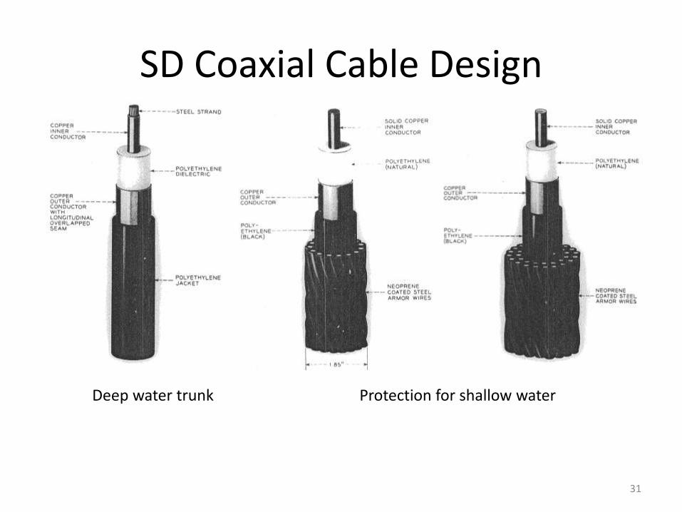
SD Coaxial Cable Design
31
Protection for shallow waterDeep water trunk

SD Repeater
32

Cable Ship
33
Cable Installation
• Landing site selection
• Cable routing considerations
• Armor selection
• Burial Requirements
– With fishing activity moving into deeper waters, cable burial is increasingly specified into deeper waters too. It is not many years ago that the 200m depth contour typically represented the end of burial operations. Today, burial may be specified to as deep as 2,000m.
34
Array Installation
• Operational need/location
• Local sound speed profile determines range of acceptable array depths
• Array must be horizontal and straight
– Extremely accurate bathymetry required
– Post installation measurements required to verify array configuration
• Real Estate that meets all the requirements
35
Topics
Acoustic Propagation (TL)
Noise Environment (AN)
Target Acoustic Characteristics (SL)
Receiving Array (AG)
U/W System
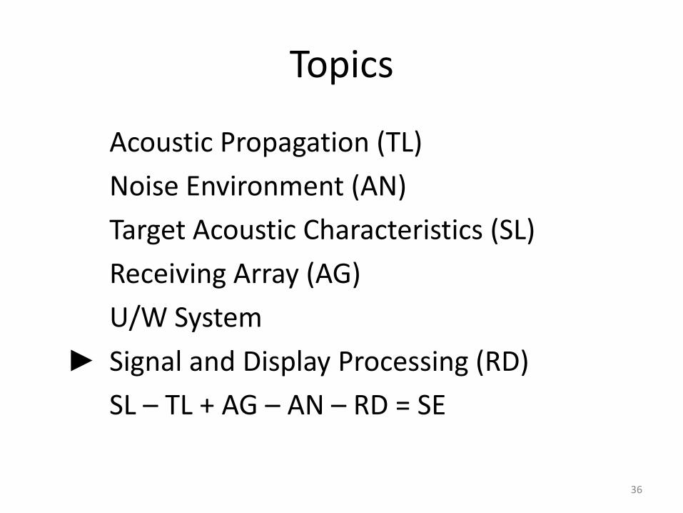
► Signal and Display Processing (RD)
SL – TL + AG – AN – RD = SE
36

37
Early System Concept
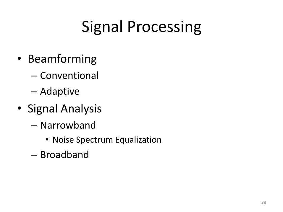
Signal Processing
• Beamforming
– Conventional
– Adaptive
• Signal Analysis
– Narrowband
• Noise Spectrum Equalization
– Broadband
38
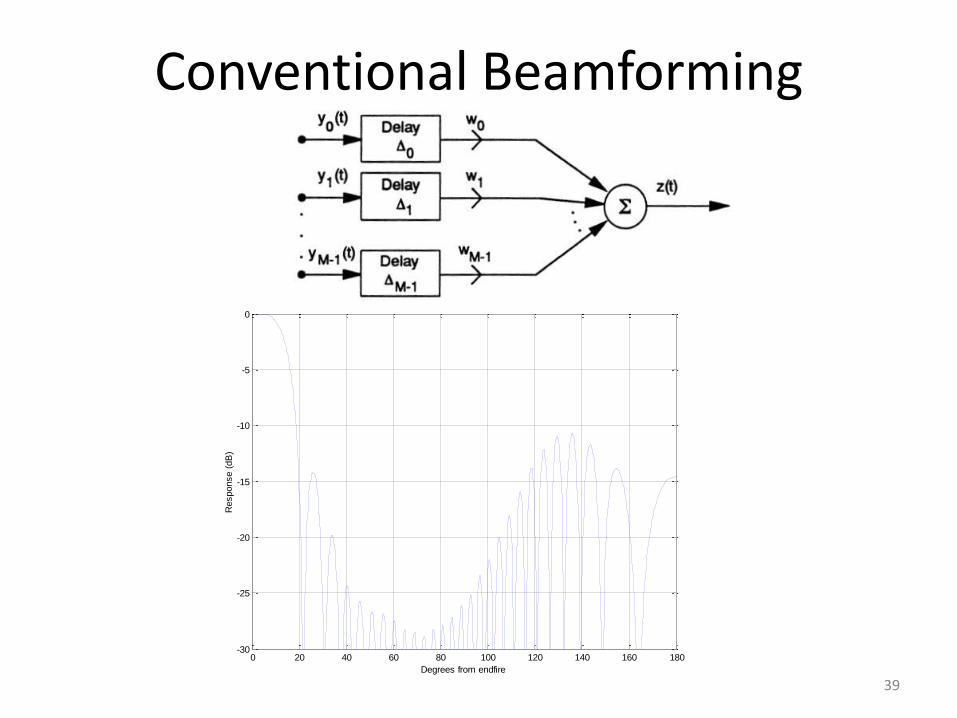
Conventional Beamforming
39
0 20 40 60 80 100 120 140 160 180-30
-25
-20
-15
-10
-5
0
Degrees from endfire
Response (
dB
)
CaseFUSS, Freq = 2fo, L/lam =14
Signal Analysis
• All signals are imbedded in noise, hence passive acoustic detection problems involve finding signals in noise.
• With some understanding of the character of the signal, the first step is to eliminate noise with different characteristics. The second step is to estimate the level of the remaining noise.
• Typically a clever way is found to present the signal data to a person who evaluates the line like signals to determine if they are threat like.
• Since submarines and surface ships move relatively slowly, time is available to do the evaluation.
40

Sonar Data Recorders
41
LOFARgram
SOSUS Workstation
• With the advances in technology Sonar Data Recorders were replaced many years ago with multi-screen workstations. Operators now have powerful tools to analyze target signatures.
42

Summary
• The SOSUS system is a highly complex passive multi technology acoustic surveillance system that has evolved with the evolution of technology. It played a major intelligence gathering role during the cold war providing accurate knowledge of the location of Soviet submarines.
43