Embed Size (px)
DESCRIPTION
The liquid propellant rocket engine (LPRE) is a proven means of propulsion.It was conceived over 100 years ago, but its firstactual construction in the United States (and in the world) was accomplished by an American, namely, Robert H. Goddard, in 1921(82 years ago). His first static hot-firing test was in 1923 and the historic first flight with a LPRE occurred in 1926. Today this technology is sufficiently well developed and proven that we can design, build, and fly with confidence any kind of LPRE. In 1940, there were only a few outstanding individuals and groups that were struggling with early research and development efforts. The LPRE capabilityhas proliferated and grown, and today there are several active U.S. companies and several government laboratories that have a maturebroad LPRE technical base.
Citation preview
JOURNAL OF PROPULSION AND POWER
Vol. 19, No. 6, November–December 2003
History of Liquid Propellant Rocket Engines in the United States
George P. SuttonLos Angeles, California 90049
I. Introduction
T he liquid propellant rocket engine (LPRE) is a proven meansof propulsion.It was conceivedover 100 years ago, but its � rst
actual construction in the United States (and in the world) was ac-complished by an American, namely, Robert H. Goddard, in 1921(82 years ago). His � rst static hot-� ring test was in 1923 and thehistoric � rst � ight with a LPRE occurred in 1926. Today this tech-nology is suf� ciently well developedand proven that we can design,build, and � y with con� denceany kind ofLPRE. In 1940, therewereonly a few outstanding individuals and groups that were strugglingwith early research and development efforts. The LPRE capabilityhas proliferated and grown, and today there are several active U.S.companies and several government laboratories that have a maturebroad LPRE technical base.
The reader shouldhaveanunderstandingof LPREs, a backgroundor exposureto someaspectof the subject.For basic informationreferto the generalRefs. 1–8 and, for more detail, to a future book by theauthor on a world wide history of LPREs, scheduledto be publishedby the AIAA in late 2004.
There is no single LPRE concept or type, but rather several thatare related and tailored to speci� c applications. All have one ormore thrust chambers (TCs), a feed system for providingthe propel-lants under pressure to the thrust chamber(s), and a control system.There are signi� cant differences between LPREs with high thrustand low thrust, cryogenic vs storable propellants, monopropellantsor bipropellants,single use or reusable, one run per � ight vs multi-ple restarts during � ight, random variable thrust or nearly constantthrust, and those with pumps or gas pressure expulsion of propel-lants in their feed systems. The history of each of these types will bediscussed.
In this paper a “successful LPRE” is de� ned as one that 1) hasbeenput intoproductionand/or 2) has � own itsmissionsatisfactorilymore thanonce.Afterall, theultimateobjectiveis to propela vehicle.There havebeenmany LPREs, enginecomponents,and propellants,but for various reasons they were never successful,and most fell bythe wayside. Yet we learned some important lessons from them.We will concentrate on some of the successful LPREs, but we willalso discuss some others that have interestingtechnologyor historicsigni� cance.
George P. Sutton has been active in the design, research, development, testing, teaching, installation and man-agement of rocket propulsion since 1943 and was personally involved in several early historic liquid propellantrocket engines and solid propellant rocket motors programs. In the aerospace industry he worked for three yearsat Aerojet Engineering Companyand for more than 25 years at Rocketdyne (now a part of The Boeing Company),where he held several positions, includingExecutive Director of Engineering and Director of Long Range Planning.His book Rocket Propulsion Elements (currently in its 7th edition) is the classical text on this subject, has beentranslated into three other languages, and is used by more than 40 colleges world wide. First published in 1949 ithas been in print longer than any other aerospace text. For 11 years he was a member of the U.S. Air Force Scienti� cAdvisory Board. In academia he was the Hunsaker Professor of Aeronautical Engineering at the MassachusettsInstitute of Technology MIT and has served on the faculty of the California Institute of Technology.He has workedfor the U.S. Government as Chief Scientist of the Department of Defense Advanced Research Projects Agency,where he started major programs, and as a project leader at the Lawrence Livermore National Laboratory. Fora few years he worked in the commercial world and has been on the board of directors of two industrial privatecompanies. He is an AIAA fellow, an author of 50 technical articles, the recipient of several professional societyawards, and is listed in Who’s Who in America.
Received 11 March 2002; revision received 3 September 2003; accepted for publication 4 September 2003. Copyright c° 2003 by the American Institute ofAeronautics and Astronautics, Inc. All rights reserved. Copies of this paper may be made for personal or internal use, on condition that the copier pay the $10.00per-copy fee to the Copyright Clearance Center, Inc., 222 Rosewood Drive, Danvers, MA 01923; include the code 0748-4658/03 $10.00 in correspondencewith the CCC.
An estimated300–350 differentLPREs havebeendesigned,built,and static tested in the United States. Because of space limitations,only a few of them have been selected for this summary paper. Foreach of those,only a few piecesof data or a � gure will be given here.If a signi� cant LPRE or outstandingaccomplishmentwas omitted, itwas not by intent, but by the lack of information available to the au-thor and/or the space limitation for this paper. Although some of the� ight vehicles driven by a LPRE (airplanes,missiles, or spacecraft)are mentioned or identi� ed here brie� y, the emphasis in this workis on the rocket engines and not on the rocket vehicles themselves.Gaseous propellant engine systems are included because they areusually groupedwith the LPREs. We will not cover solid propellantrocket motors, electrical propulsion,hybrid propulsion,and combi-nation rocket-airbreathingengines.
II. Need for LPREsWhy were LPREs used? Because they propelled certain military
and space vehiclesbetter than any other type of chemical propulsionand becausethey providedsome operatingcharacteristicsthat couldnot be duplicated at the time by any other means of propulsion.2
LPREs made it possible to build sounding rockets (1926–1960);theypropelledmilitaryaircraftandassistedwith their takeoff(1942–1970). They went into production for several early tactical missiles(1951–1973) because solid propellant rocket motors could not meetthe operating temperature limit requirements during the 1940s and1950s. LPREs were selected for all the initial ballistic missiles,helping to build up the military missile inventory needed urgentlyby the U.S. Government in the 1950s–1970s. Since 1960, LPREspropelled all of the large space launch vehicles and just about allthe U.S. spacecraft and satellites. They constitute the propulsionmachinery that drove us into the space age.
The features and performance characteristics of LPREs that al-lowed their selection for the mentioned missions, were unique andare brie� y reviewed next.2 Liquid bipropellants generally give ahigher speci� c impulse than other chemical propulsionmeans, suchas monopropellantsor thoseusing solid or hybridpropellants.Cryo-genic propellants give the highest speci� c impulse. LPREs can bedesigned over a very wide range of thrust values to � t speci� c ap-plications (by a factor of 108/. They are the only form of chemical
978
SUTTON 979
propulsion that can be designed for quick restart, fast pulsing, andready reuse. They can be designed for a random thrust variation oncommand. They have been uniquely suitable for controlling quickattitude (pitch, yaw, or roll) changes and minor velocity changes ofindividual stages of missiles, space launch vehicles, spacecraft, andsatellites. A precise repeatable thrust termination permits an accu-rate terminal � ight velocity.LPREs can be functionallycheckedoutand even fully tested before they are used. An engine-outcapabilitycan be designed into engine clusters. A remarkably high reliabilityhas been achieved in production LPREs. Lightweight LPREs haveallowed � ight vehicles to achieve a high propellant fraction and ahigh vehicle mass ratio. Instant readiness has been achieved withstorablepropellants.These propellantshavebeen stored for 20 yearsin a vehicle.
All common propellants used today can discharge a very cleantransparent exhaust gas without smoke. Gas from certain of thestorable propellants can give a trace of smoke, but their particulatesdo not usually form a noticeable deposit on sensitive vehicle sur-faces, such as windows. The exhaust gas of today’s LPREs is nottoxic and environmentally friendly.
III. Technology Trends and ChangesThroughout this LPRE history, one can discern some technical
trends, growth patterns, or directions for improvement. Some arebrie� y listed later. There are several other trends, but their write-uphad to be omitted from this paper. They were thrust vector control,injectors, gas generators or preburners, major reductions of inertengine mass, extending or uprating a family of existing engines,and reducing lifetime costs. They are planned to be included in theupcoming book version.
A. Expanding the Range of the Thrust, 0.01–1,800,000Pounds Force (Refs. 1–4)
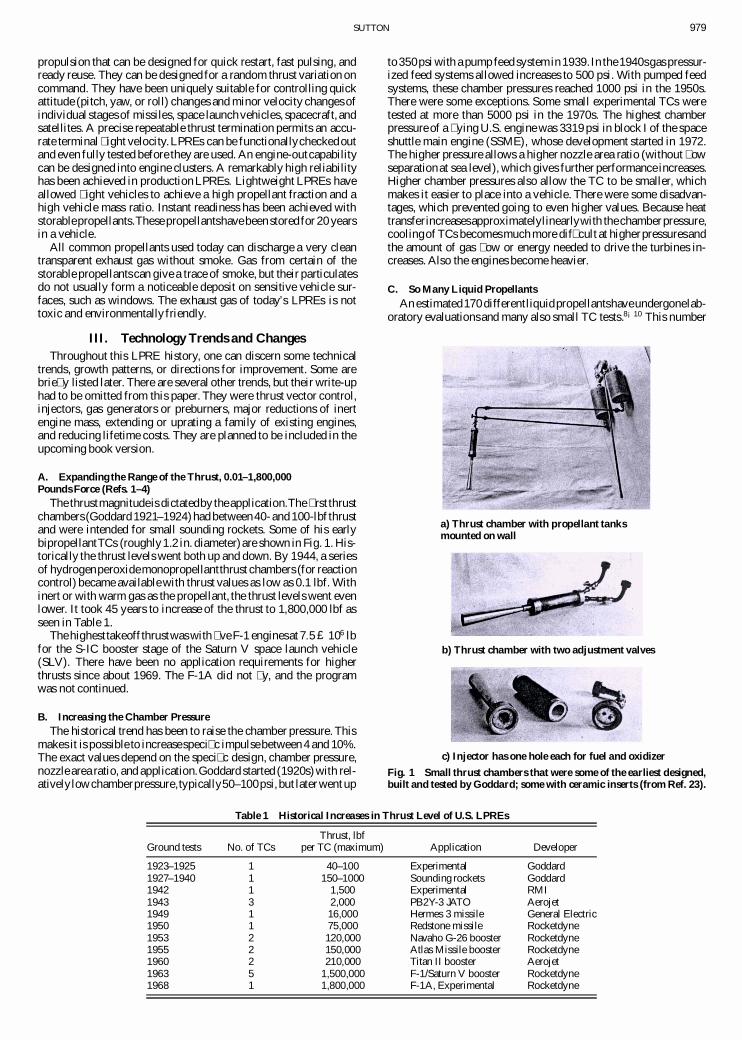
The thrustmagnitudeis dictatedby theapplication.The � rst thrustchambers (Goddard 1921–1924)had between40-and 100-lbf thrustand were intended for small sounding rockets. Some of his earlybipropellantTCs (roughly1.2 in. diameter)are shown in Fig. 1. His-torically the thrust levels went both up and down. By 1944, a seriesof hydrogenperoxidemonopropellantthrust chambers (for reactioncontrol) became available with thrust values as low as 0.1 lbf. Withinert or with warm gas as the propellant, the thrust levels went evenlower. It took 45 years to increase of the thrust to 1,800,000 lbf asseen in Table 1.
The highesttakeoffthrustwas with � veF-1 enginesat 7:5 £ 106 lbfor the S-IC booster stage of the Saturn V space launch vehicle(SLV). There have been no application requirements for higherthrusts since about 1969. The F-1A did not � y, and the programwas not continued.
B. Increasing the Chamber PressureThe historical trend has been to raise the chamber pressure. This
makes it is possible to increasespeci� c impulsebetween 4 and 10%.The exact values depend on the speci� c design, chamber pressure,nozzle area ratio, and application.Goddard started (1920s)with rel-ativelylowchamberpressure,typically50–100psi, but later went up
Table 1 Historical Increases in Thrust Level of U.S. LPREs
Thrust, lbfGround tests No. of TCs per TC (maximum) Application Developer
1923–1925 1 40–100 Experimental Goddard1927–1940 1 150–1000 Sounding rockets Goddard1942 1 1,500 Experimental RMI1943 3 2,000 PB2Y-3 JATO Aerojet1949 1 16,000 Hermes 3 missile General Electric1950 1 75,000 Redstone missile Rocketdyne1953 2 120,000 Navaho G-26 booster Rocketdyne1955 2 150,000 Atlas Missile booster Rocketdyne1960 2 210,000 Titan II booster Aerojet1963 5 1,500,000 F-1/Saturn V booster Rocketdyne1968 1 1,800,000 F-1A, Experimental Rocketdyne
to 350psi with a pump feed systemin 1939.In the1940sgas pressur-ized feed systems allowed increases to 500 psi. With pumped feedsystems, these chamber pressures reached 1000 psi in the 1950s.There were some exceptions. Some small experimental TCs weretested at more than 5000 psi in the 1970s. The highest chamberpressure of a � ying U.S. engine was 3319 psi in block I of the spaceshuttle main engine (SSME), whose development started in 1972.The higher pressure allows a higher nozzle area ratio (without � owseparationat sea level), which gives further performance increases.Higher chamber pressures also allow the TC to be smaller, whichmakes it easier to place into a vehicle. There were some disadvan-tages, which prevented going to even higher values. Because heattransferincreasesapproximatelylinearlywith thechamberpressure,coolingof TCs becomesmuch more dif� cult at higherpressuresandthe amount of gas � ow or energy needed to drive the turbines in-creases. Also the engines become heavier.
C. So Many Liquid PropellantsAn estimated170 differentliquidpropellantshaveundergonelab-
oratory evaluationsand many also small TC tests.8¡10 This number
a) Thrust chamber with propellant tanksmounted on wall
b) Thrust chamber with two adjustment valves
c) Injector has one hole each for fuel and oxidizer
Fig. 1 Small thrust chambers that were some of the earliest designed,built and tested by Goddard; some with ceramic inserts (from Ref. 23).
980 SUTTON
does not include any minor changes in the propellant formulation(such as small changes in NO2 percentage in nitric acid) and in thepropellant additives, such as gelling agents, corrosion inhibitors, orstabilizers.1¡3 More than 25 differentpropellant combinationshavebeen � own in U.S. LPREs.
Early U.S. efforts were with liquid oxygen (LOX) gasoline(Goddard1923),nitricacid/aniline[GuggenhiemAeronauticalLab-oratory (GALCIT) and Aerojet 1940–1955], and LOX/75% alcohol[ReactionMotors, Inc. (RMI) 1942].There was no discernibletrendin the earlypropellantselectionsand each project team, company,orgovernmentagencypicked the propellantthey thoughtmost suitablefor their application. Therefore, U.S. LPREs were developed, pro-duced, and � own with a variety of propellant combinations, suchas those just mentioned. Flying LPREs have also used ammonia,90% hydrogen peroxide, nitric acid, kerosene, mixtures of nitro-gen oxide and nitric acid, 75 and 92% alcohol, pure hydrazine,mixtures of kerosene and unsymmetrical dimethylhydrazine(UDMH), monomethylhydrazine (MMH), gelled propellants, andothers.
A yearning for higher energy denser propellants led to programsof investigating � uorine, chlorine, and/or � uorine containing com-pounds, boron materials, and several other exotic materials or mix-tures in the 1960s and 1970s. The effort was extensive and includedground � ring of TCs and three complete engines with some ofthese toxic, corrosive, and highly � ammable high-energy propel-lants.None were selectedfor a � ying engine.Fluorineas an oxidizercan give a higher speci� c impulse and higher average densities thanLOX, but it and other high-energy chemicals were not consideredto be practical. The decision to stop these high-energy propellantinvestigationswas due in part to the potential drastic consequencesof a major engine failure and/or a spill of propellantsand their effecton people, equipment, or environment.
All of this effort did not lead to a universally acceptable singleliquid propellant combination. All selections were a compromisebetween good qualities (high performance, high density, easy start,low cost, or stable, long time storage) and bad qualities (corrosive,� ammable, toxic, prone to storage decay, high vapor pressures, orcombustioninstability)and dependedon the application.After yearsof operationalexperience� ve propellantcombinationsseem to haveemerged as being practical to use with current space applications,and they are listed in Table 2. Not mentioned in this table are pro-pellants for applications that are today obsolete, such as jet-assistedtake offs (JATOs), sounding rockets, aircraft propulsion,or tacticalmissiles with LPREs.
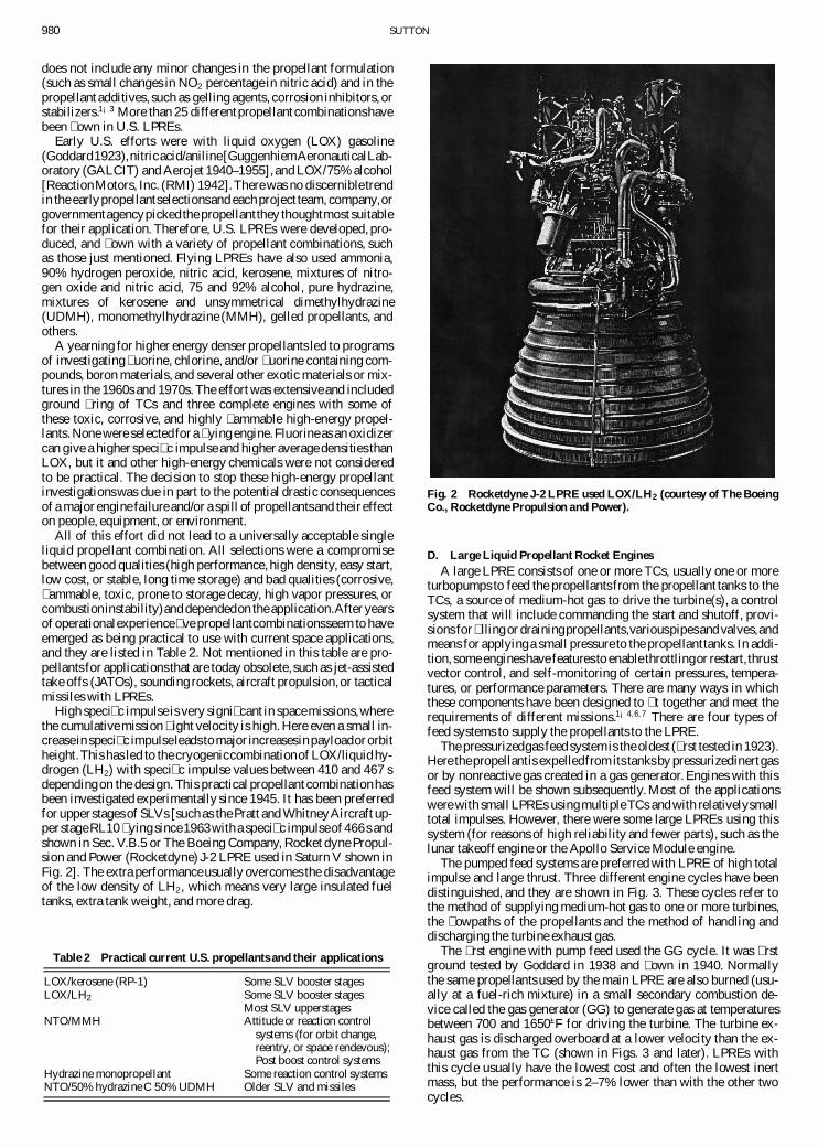
High speci� c impulse is very signi� cant in spacemissions,wherethe cumulative mission � ight velocity is high. Here even a small in-creasein speci� c impulseleads to major increasesin payloador orbitheight.This has led to the cryogeniccombinationof LOX/liquid hy-drogen (LH2) with speci� c impulse values between 410 and 467 sdependingon the design. This practical propellant combinationhasbeen investigated experimentally since 1945. It has been preferredfor upper stages of SLVs [suchas the Pratt and WhitneyAircraft up-per stageRL10 � ying since1963with a speci� c impulseof 466s andshown in Sec. V.B.5 or The Boeing Company, Rocket dyne Propul-sion and Power (Rocketdyne) J-2 LPRE used in Saturn V shown inFig. 2]. The extra performanceusually overcomes the disadvantageof the low density of LH2 , which means very large insulated fueltanks, extra tank weight, and more drag.
Table 2 Practical current U.S. propellants and their applications
LOX/kerosene (RP-1) Some SLV booster stagesLOX/LH2 Some SLV booster stages
Most SLV upperstagesNTO/MMH Attitude or reaction control
systems (for orbit change,reentry, or space rendevous);Post boost control systems
Hydrazine monopropellant Some reaction control systemsNTO/50% hydrazine C 50% UDMH Older SLV and missiles
Fig. 2 Rocketdyne J-2 LPRE used LOX/LH2 (courtesy of The BoeingCo., Rocketdyne Propulsion and Power).
D. Large Liquid Propellant Rocket EnginesA large LPRE consists of one or more TCs, usually one or more
turbopumps to feed the propellants from the propellant tanks to theTCs, a source of medium-hot gas to drive the turbine(s), a controlsystem that will include commanding the start and shutoff, provi-sions for � llingor drainingpropellants,variouspipesand valves,andmeans for applyinga small pressure to the propellanttanks. In addi-tion, some engineshave features to enable throttlingor restart, thrustvector control, and self-monitoring of certain pressures, tempera-tures, or performance parameters. There are many ways in whichthese components have been designed to � t together and meet therequirements of different missions.1¡4;6;7 There are four types offeed systems to supply the propellants to the LPRE.
The pressurizedgas feed systemis the oldest (� rst tested in 1923).Here thepropellantis expelledfrom its tanksby pressurizedinertgasor by nonreactive gas created in a gas generator. Engines with thisfeed system will be shown subsequently. Most of the applicationswere with small LPREs usingmultipleTCs and with relativelysmalltotal impulses. However, there were some large LPREs using thissystem (for reasons of high reliability and fewer parts), such as thelunar takeoff engine or the Apollo Service Module engine.
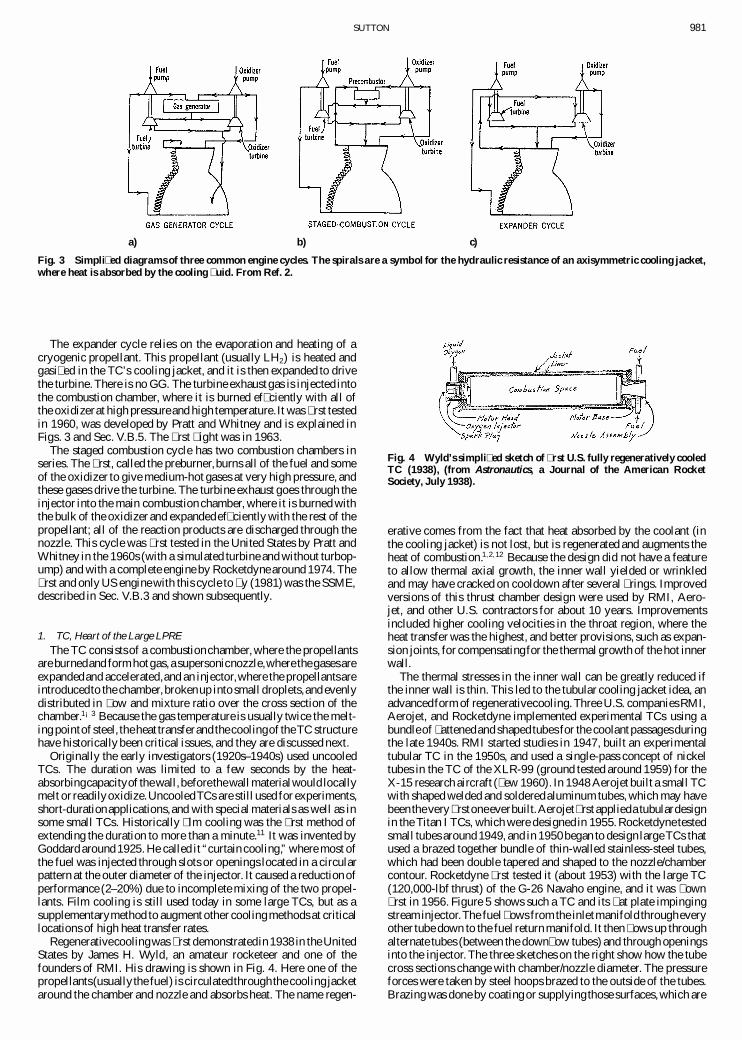
The pumped feed systems are preferred with LPRE of high totalimpulse and large thrust. Three different engine cycles have beendistinguished, and they are shown in Fig. 3. These cycles refer tothe method of supplying medium-hot gas to one or more turbines,the � owpaths of the propellants and the method of handling anddischarging the turbine exhaust gas.
The � rst engine with pump feed used the GG cycle. It was � rstground tested by Goddard in 1938 and � own in 1940. Normallythe same propellants used by the main LPRE are also burned (usu-ally at a fuel-rich mixture) in a small secondary combustion de-vice called the gas generator (GG) to generate gas at temperaturesbetween 700 and 1650±F for driving the turbine. The turbine ex-haust gas is discharged overboard at a lower velocity than the ex-haust gas from the TC (shown in Figs. 3 and later). LPREs withthis cycle usually have the lowest cost and often the lowest inertmass, but the performance is 2–7% lower than with the other twocycles.
SUTTON 981
a) b) c)
Fig. 3 Simpli� ed diagrams of three common engine cycles. The spirals are a symbol for the hydraulic resistance of an axisymmetric cooling jacket,where heat is absorbed by the cooling � uid. From Ref. 2.
The expander cycle relies on the evaporation and heating of acryogenic propellant. This propellant (usually LH2) is heated andgasi� ed in the TC’s cooling jacket, and it is then expanded to drivethe turbine.There is no GG. The turbine exhaust gas is injected intothe combustion chamber, where it is burned ef� ciently with all ofthe oxidizerat high pressureand high temperature.It was � rst testedin 1960, was developed by Pratt and Whitney and is explained inFigs. 3 and Sec. V.B.5. The � rst � ight was in 1963.
The staged combustion cycle has two combustion chambers inseries. The � rst, called the preburner,burns all of the fuel and someof the oxidizer to give medium-hot gases at very high pressure, andthese gases drive the turbine. The turbine exhaust goes through theinjector into the main combustion chamber, where it is burned withthe bulk of the oxidizer and expandedef� ciently with the rest of thepropellant; all of the reaction products are discharged through thenozzle. This cycle was � rst tested in the United States by Pratt andWhitney in the 1960s (with a simulated turbine and without turbop-ump) and with a complete engine by Rocketdyne around 1974. The� rst and only US engine with this cycle to � y (1981) was the SSME,described in Sec. V.B.3 and shown subsequently.
1. TC, Heart of the Large LPREThe TC consists of a combustionchamber, where the propellants
are burnedand formhotgas, a supersonicnozzle,where thegasesareexpandedand accelerated,and an injector,where the propellantsareintroducedto the chamber,brokenup into small droplets,and evenlydistributed in � ow and mixture ratio over the cross section of thechamber.1¡3 Because the gas temperature is usually twice the melt-ing pointof steel, theheat transferand thecoolingof theTC structurehave historically been critical issues, and they are discussed next.
Originally the early investigators (1920s–1940s) used uncooledTCs. The duration was limited to a few seconds by the heat-absorbingcapacityof thewall,beforethewall materialwould locallymelt or readilyoxidize.UncooledTCs are still used for experiments,short-durationapplications,and with special materials as well as insome small TCs. Historically � lm cooling was the � rst method ofextending the duration to more than a minute.11 It was invented byGoddard around 1925. He called it “curtain cooling,” where most ofthe fuel was injected through slots or openings located in a circularpattern at the outer diameter of the injector. It caused a reduction ofperformance (2–20%) due to incomplete mixing of the two propel-lants. Film cooling is still used today in some large TCs, but as asupplementarymethod to augment other coolingmethods at criticallocations of high heat transfer rates.
Regenerativecoolingwas � rst demonstratedin 1938 in the UnitedStates by James H. Wyld, an amateur rocketeer and one of thefounders of RMI. His drawing is shown in Fig. 4. Here one of thepropellants(usuallythe fuel) is circulatedthroughthe coolingjacketaround the chamber and nozzle and absorbs heat. The name regen-
Fig. 4 Wyld’s simpli� ed sketch of � rst U.S. fully regeneratively cooledTC (1938), (from Astronautics, a Journal of the American RocketSociety, July 1938).
erative comes from the fact that heat absorbed by the coolant (inthe cooling jacket) is not lost, but is regenerated and augments theheat of combustion.1;2;12 Because the design did not have a featureto allow thermal axial growth, the inner wall yielded or wrinkledand may have cracked on cooldown after several � rings. Improvedversions of this thrust chamber design were used by RMI, Aero-jet, and other U.S. contractors for about 10 years. Improvementsincluded higher cooling velocities in the throat region, where theheat transfer was the highest, and better provisions, such as expan-sion joints, for compensatingfor the thermal growth of the hot innerwall.
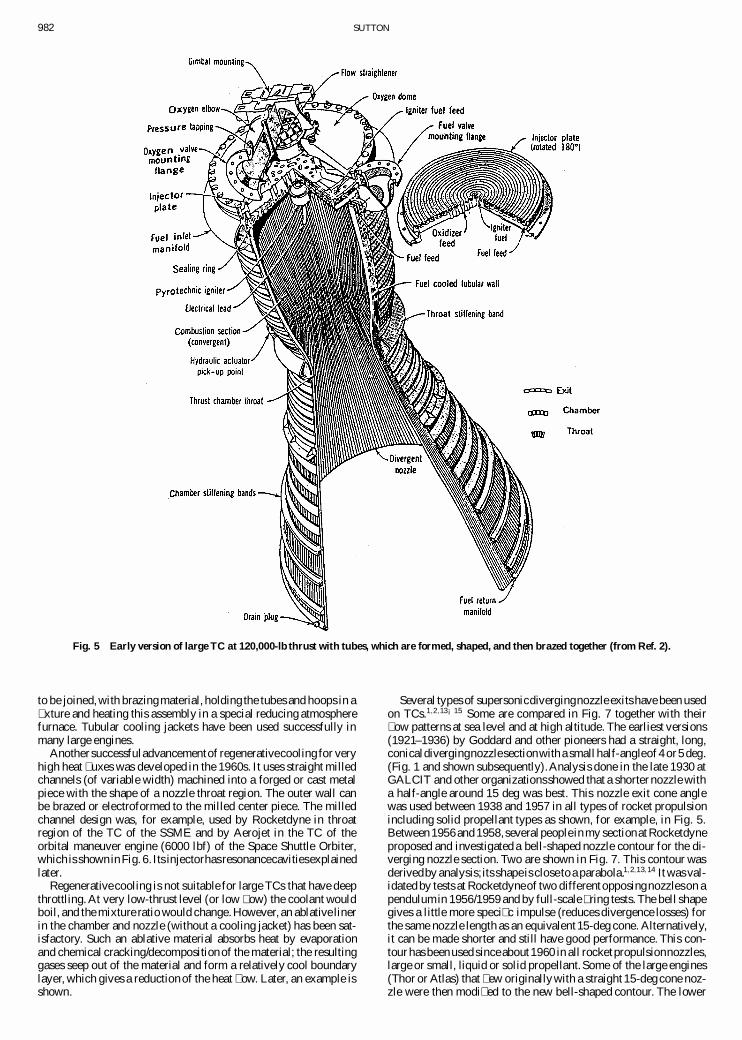
The thermal stresses in the inner wall can be greatly reduced ifthe inner wall is thin. This led to the tubular cooling jacket idea, anadvancedform of regenerativecooling.Three U.S. companiesRMI,Aerojet, and Rocketdyne implemented experimental TCs using abundleof � attenedand shaped tubes for the coolant passagesduringthe late 1940s. RMI started studies in 1947, built an experimentaltubular TC in the 1950s, and used a single-pass concept of nickeltubes in the TC of the XLR-99 (ground tested around 1959) for theX-15 research aircraft (� ew 1960). In 1948 Aerojet built a small TCwith shaped welded and solderedaluminum tubes, which may havebeenthevery� rstoneeverbuilt.Aerojet� rst applieda tubulardesignin the Titan I TCs, which were designed in 1955. Rocketdyne testedsmall tubes around 1949, and in 1950began to design largeTCs thatused a brazed together bundle of thin-walled stainless-steel tubes,which had been double tapered and shaped to the nozzle/chambercontour. Rocketdyne � rst tested it (about 1953) with the large TC(120,000-lbf thrust) of the G-26 Navaho engine, and it was � own� rst in 1956. Figure 5 shows such a TC and its � at plate impingingstreaminjector.The fuel � ows from the inletmanifold througheveryother tube down to the fuel return manifold. It then � ows up throughalternate tubes (between the down� ow tubes) and through openingsinto the injector. The three sketches on the right show how the tubecross sections change with chamber/nozzle diameter. The pressureforces were taken by steel hoops brazed to the outside of the tubes.Brazing was done by coatingor supplyingthose surfaces,which are
982 SUTTON
Fig. 5 Early version of large TC at 120,000-lb thrust with tubes, which are formed, shaped, and then brazed together (from Ref. 2).
to be joined, with brazingmaterial, holding the tubes and hoops in a� xture and heating this assembly in a special reducing atmospherefurnace. Tubular cooling jackets have been used successfully inmany large engines.
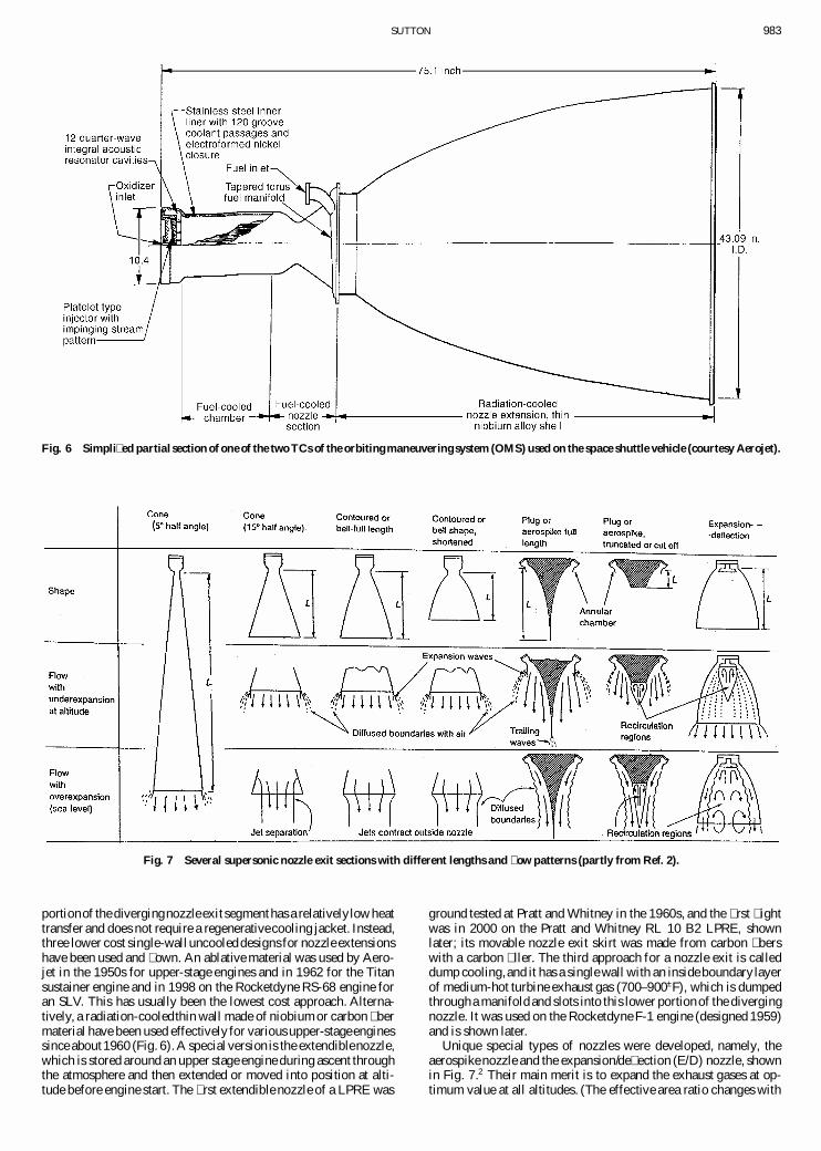
Another successfuladvancementof regenerativecooling for veryhigh heat � uxes was developed in the 1960s. It uses straight milledchannels (of variable width) machined into a forged or cast metalpiece with the shape of a nozzle throat region. The outer wall canbe brazed or electroformed to the milled center piece. The milledchannel design was, for example, used by Rocketdyne in throatregion of the TC of the SSME and by Aerojet in the TC of theorbital maneuver engine (6000 lbf) of the Space Shuttle Orbiter,which is shownin Fig. 6. Its injectorhasresonancecavitiesexplainedlater.
Regenerativecooling is not suitable for large TCs that have deepthrottling. At very low-thrust level (or low � ow) the coolant wouldboil, and the mixture ratio would change.However, an ablative linerin the chamber and nozzle (without a cooling jacket) has been sat-isfactory. Such an ablative material absorbs heat by evaporationand chemical cracking/decompositionof the material; the resultinggases seep out of the material and form a relatively cool boundarylayer, which gives a reduction of the heat � ow. Later, an example isshown.
Several types of supersonicdivergingnozzle exits have been usedon TCs.1;2;13¡15 Some are compared in Fig. 7 together with their� ow patterns at sea level and at high altitude. The earliest versions(1921–1936) by Goddard and other pioneers had a straight, long,conicaldivergingnozzlesectionwith a small half-angleof 4 or 5 deg.(Fig. 1 and shown subsequently).Analysis done in the late 1930 atGALCIT and other organizationsshowed that a shorter nozzle witha half-angle around 15 deg was best. This nozzle exit cone anglewas used between 1938 and 1957 in all types of rocket propulsionincluding solid propellant types as shown, for example, in Fig. 5.Between 1956and 1958,severalpeoplein my sectionat Rocketdyneproposed and investigated a bell-shaped nozzle contour for the di-verging nozzle section. Two are shown in Fig. 7. This contour wasderivedby analysis;its shapeis close to a parabola.1;2;13;14 It was val-idated by tests at Rocketdyneof two differentopposingnozzleson apendulumin 1956/1959 and by full-scale � ring tests. The bell shapegives a little more speci� c impulse (reduces divergence losses) forthe same nozzle length as an equivalent 15-deg cone. Alternatively,it can be made shorter and still have good performance. This con-tour has beenused since about1960 in all rocketpropulsionnozzles,large or small, liquid or solid propellant.Some of the large engines(Thor or Atlas) that � ew originallywith a straight 15-deg cone noz-zle were then modi� ed to the new bell-shaped contour. The lower
SUTTON 983
Fig. 6 Simpli� ed partial section of one of the two TCs of the orbiting maneuvering system (OMS) used on the space shuttle vehicle (courtesy Aerojet).
Fig. 7 Several supersonic nozzle exit sections with different lengths and � ow patterns (partly from Ref. 2).
portionof the divergingnozzleexit segmenthas a relativelylow heattransfer and does not require a regenerativecooling jacket. Instead,three lower cost single-walluncooled designs for nozzle extensionshave been used and � own. An ablative material was used by Aero-jet in the 1950s for upper-stage engines and in 1962 for the Titansustainer engine and in 1998 on the Rocketdyne RS-68 engine foran SLV. This has usually been the lowest cost approach. Alterna-tively, a radiation-cooledthin wall made of niobium or carbon � bermaterial have been used effectively for various upper-stageenginessince about1960 (Fig. 6). A special version is the extendiblenozzle,which is stored around an upper stage engine during ascent throughthe atmosphere and then extended or moved into position at alti-tude before engine start. The � rst extendible nozzle of a LPRE was
ground tested at Pratt and Whitney in the 1960s, and the � rst � ightwas in 2000 on the Pratt and Whitney RL 10 B2 LPRE, shownlater; its movable nozzle exit skirt was made from carbon � berswith a carbon � ller. The third approach for a nozzle exit is calleddump cooling,and it has a single wall with an inside boundary layerof medium-hot turbine exhaust gas (700–900±F), which is dumpedthrougha manifold and slots into this lower portionof the divergingnozzle. It was used on the Rocketdyne F-1 engine (designed 1959)and is shown later.
Unique special types of nozzles were developed, namely, theaerospike nozzle and the expansion/de� ection (E/D) nozzle, shownin Fig. 7.2 Their main merit is to expand the exhaust gases at op-timum value at all altitudes. (The effective area ratio changes with

984 SUTTON
Fig. 8 Technician is holding two of the turbopumps developed by Goddard (from Ref. 24).
altitude.) This allows a slightly higher time-averaged speci� c im-pulse or thrust during � ight, when compared to a � xed conven-tional nozzle. The engine length can be very short with a cutoffspike or a shortened E/D nozzle, saving some inert vehicle massand drag. Five different experimental aerospike engines have beenground tested by Rocketdyne (using LOX/LH2) with thrusts be-tween 50,000and 400,000lbf includinga linear aerospikeversion.15
Rocketdyne also ground tested two versions of an E/D engines [us-ing nitrogen tetroxide (NTO)/Aerozine 50] in the early 1960s at50,000- and 10,000-lbf levels. None of these projects with specialnozzles have been continued.
2. Turbopumps1;2;16;17
The turbopump (TP) is a key component for a pump-fed LPREand an engineering intensive, high-precision, high-speed piece ofrotatingmachinery.The � rst turbine-drivencentrifugalpumps weretested by Goddard in 1934 (Sec. IV.A). Two of his TPs are shown inFig. 8. They had ball bearings, shrouded turbine blades, and pumpoutletdiffusers.(One is shown extendingfrom the pump in theupperright.) A small arc of the blades of the two turbines were immersedin the exhaust gas of the main nozzle (over 5000±F), and he experi-encedfrequent turbinefailures.Therefore,Goddarddevelopeda GG(1938) that had a lower gas temperature.The � rst version had threepropellants (LOX, gasoline, and water as a diluting/cooling � uid).The TPs were small (low � ow) and inef� cient.The � rstLPRE with aTP and a GG was testedby Goddard in 1939and � own in a soundingrocket in 1940. In 1942 he used a fuel-rich GG without water.
The early TPs for JATO and aircraft superperformance (1943–1950)hada turbineandboth thepropellantpumpson the samesingleshaft. The � rst large U.S. TP (Redstone engine designed 1949) hadtwo in-line shafts, a coupling, and an aluminum turbine becausethis was a proven German technology on the V-2 engine. The GGat that time used monopropellant80% hydrogen peroxide with gastemperatures of about 700±F.
Historically the large U.S. TPs of the 1950sand 1960sused a gearcase that allowed a turbine to rotate at a higher speed than one orboth of the propellantpumps becausethis allowedbetter turbine andpump ef� ciencies. This resulted in a lower GG � ow and a slightlybetter engine performance than a single-shaft TP. Figure 9 shows ageared turbopump as used with the Atlas/Thor/ H-1 (Saturn I SLV)family of boosterLPREs. Initiallyoil was supplied from a small oilpump to lubricate and cool the gears and the bearings, but the oilwas then replaced by kerosene fuel. A gear case was used for theTitan family of LPRES to drive the two pumps at different speeds.
Fig. 9 Sectioned view of the type of turbopump with a gear case usedin the Rocketdyne Thor, Jupiter, Atlas booster, and H-1 engines (fromRef. 2).
The steel alloy turbine was usually driven by a GG, which used thesame propellants as the main TC (but usually at a fuel rich mixtureratio), resulting in a gas between 1300 and 1650±F. A gear case wasalso used on the Pratt and Whitney family of RL-10 engines to allowthe oxidizer pump to rotate slower than the fuel pump.
An inducer impeller ahead of and on the same shaft as the mainpump impellerwasusedduringWorldWarII in theTP of theGermanWalter aircraft rocket engine. It provided for better cavitation resis-tance of the main pump impellers, and it allowed the tank pressureto be lowered, resulting in a weight reductionof the propellant tank.It can also allow the main pump to run at a higher speed, which inturn allows a reduction of inert TP weight. The United States waslate in adopting this clever innovation.Several of the U.S. LPRE TPthat were already in productionwere changed in the 1950s to use re-designed pumps, which included inducer impellers. This happenedto the Thor and Atlas engines. An inducer can be seen in Fig. 9.
Goddard’s concept of separateTP assemblies for the fuel and theoxidizerpump was revivedseveraldecades later for propellantcom-binations where the fuel and the oxidizer have very different densi-ties. It was usedwith LOX/LH2 engines,such as the J-2 (Rocketdyne
SUTTON 985
1960 design), the SSME (1972 design), and the RS-68 (1997 de-sign), in part because it gives a smaller and lighter design and ifavoids the complexity of a gear case. Major design advanced weremade in TPs in recent years.2;16;18
E. Small Liquid Propellant Rocket EnginesThese small engines with multiple thrust chambers (often called
thrusters) have a very important role for the vehicles’ � ightcontrol.2;3 They were and are still used for trajectory changes, atti-tude control (pitch, yaw, and roll), deorbit maneuvers, station keep-ing, rendezvousmaneuvers,or � y wheel desaturation,or for settlingliquid propellantsin a zero-gravity� ight beforemain engine restart.Although a large LPRE is usually assembled and delivered in a sin-gle package, a small LPRE, with multiple TCs (placed in severaldifferent locations in a vehicle), is normally delivered in severalpieces. Thrust levels are typically between 1 and 100 lbf, but therewere some that were larger (1000 lbf or more). They generally usestorable propellants and a pressurized gas feed system. There wereseveraldifferentways to obtaina small thrust, and theyare explainedbrie� y in their approximatehistorical sequence.More details are inSec. V.
The � rst solution for attitude control was the orderly expulsionof an inert cold gas, such as air or nitrogen, which was stored athigh pressure and exhausted through simple valves, regulators, andmultiple nozzles. Cold gas for attitude control was used starting inthe late 1940s and continuing sporadically until about 1980. Thesesystems were simple, low cost, reliable, and ran at ambient tem-peratures. However the speci� c impulse was low (around 70 s) andthe systems were heavy, adding to the inert mass of the vehicle.They were used on many early satellites and for roll control onsome upper stages.Several companieshavebuilt and � own cold-gasthrusters.
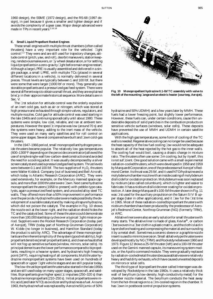
In the 1947–1966 period, small monopropellanthydrogenperox-ide thrusters became popular. The relatively low gas temperatures(600–1300±F dependingon the peroxideconcentration)allowed theuse of simple single-wall low-carbon-steelconstructionand avoidedthe need for a cooling jacket. It was usually decomposedby a silverscreencatalystand used a pressurizedgas feed system.Thrust levelswere between 0.1 and 100 lbf. The two suppliers of H2O2 thrusterswere Walter Kidde & Company (out of business) and Bell Aircraft,which today is Atlantic Research Corporation (ARC). They wereused extensively, for example, on the Mercury manned space cap-sule, and more than 1000 thrusterswere � own. Next came hydrazinemonopropellant thrusters (1958 to present) with pebble-type cata-lysts, again a pressurized feed system, and uncooled alloy steel TCwalls. They offered more than a 50% improvement in performanceover theperoxide.Hydrazinethrustersweremadepossibleby thede-velopmentof a suitable catalystand by making ultrapurehydrazine,which did not poison the catalyst. The example in Fig. 10 showsthe nozzle exit at the lower right, and the radiation shield hides theTC and the catalyst bed. Some of these thrusters could demonstratemore than 100,000start/stop cycles over a typical � ight mission pe-riod. Suppliers were the Rocket Research Corporation (today partof Aerojet), TRW (today part of Northrop Grumman Corporation)W. Kidde (no longer in business), and Hamilton Standard (todaythe product is sold by ARC). The advantage of these monopropel-lants are the inherentsimplicityof the system (good reliability),highpropellantdensities(small propellanttanks),and cleanexhauststhatwill not fog up sensitive surfaces (window, mirrors, solar cells). Itsprincipaldemerits are the lower performancecomparedto bipropel-lants, resulting in a heavier system, and hydrazine’s high freezingpoint (34±F), requiring heatingof all components.Multithrusterhy-drazine monopropellant systems have been used on hundreds ofspacecraft or upper � ight vehicle stages and are still popular today.
The low-thrustbipropellantthrusters also started in the late 1950sand are still used today on many upper stages, spacecraft, and satel-lites. Bipropellants give higher speci� c impulses (250–320 s) thanhydrazine monopropellant(210–250 s). Initial propellantswere ni-tric acid (and later NTO) as oxidizerand hydrazineas a fuel.Around1963, the hydrazinefuel was replacedby Aerozine50 (a mix of 50%
Fig. 10 Monopropellant hydrazine 0.1-lbf TC assembly with valve tothe left of the mounting � ange and an electric heater (courtesy, Aerojet).
hydrazine and 50% UDMH) and a few years later by MMH. Thesefuels had a lower freezing point, but slightly lower performance.However, these fuels can, under certain conditions, cause thin un-desirable deposits of solid particles in the combustion products onsensitive vehicle surfaces (windows, solar cells). These depositshave prevented the use of MMH and UDMH in certain satelliteapplications.
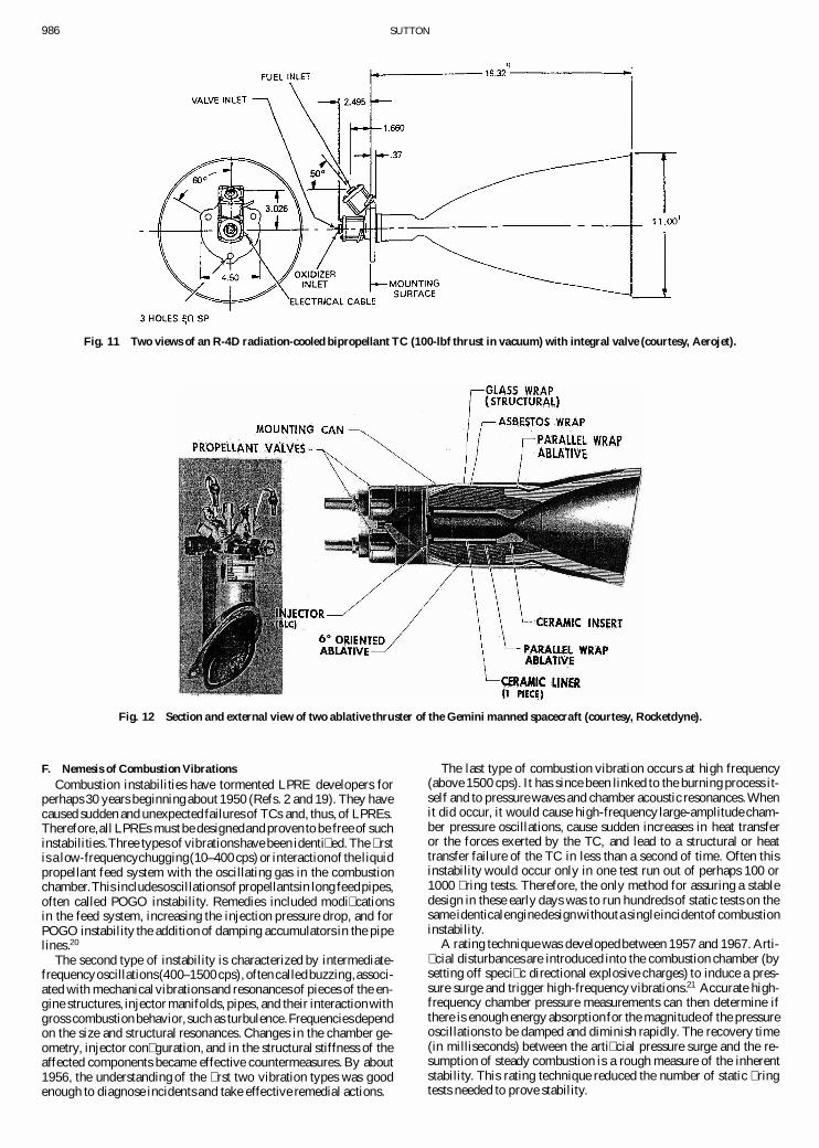
With the high gas temperatures, some form of cooling of the TCwalls is needed.Regenerativecoolingcan no longerbe used becausethe heat capacityof the low fuel cooling � ow would not be adequateto absorb all of the heat rejected by the hot gas to the inner walls.The cooling fuel would boil, causing a drastic change in mixtureratio. The thrusters often use some � lm cooling, but by ityself, thisis not suf� cient. One good solution came with a small experimentalradiation-cooledthrusters,which were developed in 1958 and 1959byMarquardtCorporation,oneof the predecessorsofAerojet’s Red-mond Center. Its thrust was 25 lbf, and it used NTO/hydrazineand amolybdenumchambernozzlewith an insidecoatingofmolybdenumdisilicide for oxidation protection.Molybdenumwas soon replacedby niobium (also called columbium), which is lighter and easier tofabricate. It has a niobium disilicide inner coating for oxidationpro-tection.A later designMarquardt’s 100-lbf thrustershown in Fig. 11was � rst used for the auxiliary propulsionon the Saturn S IV B up-per stage (later in other applications), and it � ew for the � rst timein 1965. Most of these radiation-cooledbipropellant thrusters withniobium chambers have been produced by the predecessorof Aero-jet’s Redmond Center, Northrop Grumman (NG) (formerly TRW),or ARC.
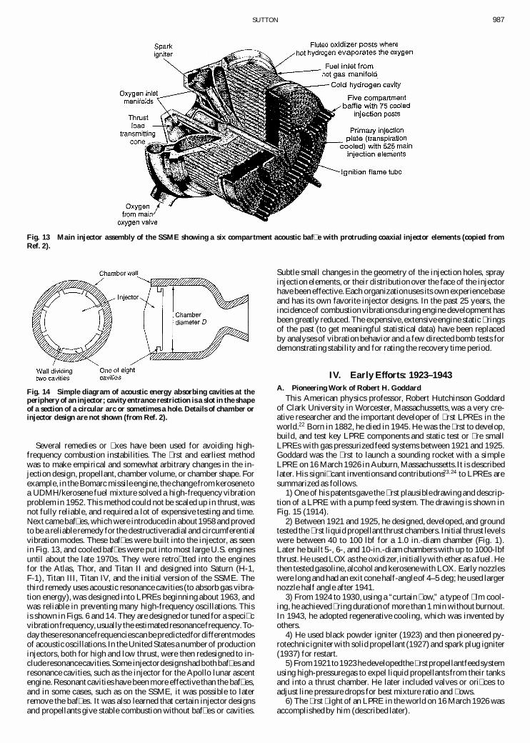
Ablative linerswere also an early solutionfor small thrusterswithmany starts. The ablative liner is made of glass, Kevlar®, or carbon� berswoven in a � ber cloth in a plasticmatrix,and thecloth is laid inlayersbefore heating and compressingthe material and surroundingit by a metal shell. Sometimes a ceramic sleeve or a graphite nozzleinsert is used to minimizeerosion.Small ablativetype thrustersweredevelopedmostly by NG (TRW) and Rocketdynebetween1960and1973. Figure 12 shows a 25-lbf thruster (left) and a 100-lbf thrusterused on the Gemini manned capsule, its maneuvering system mod-ule, or the Apollo command module. They were gradually replacedby radiation-cooledmetal thrustersbecauseablativeswere relativelyheavy and had dirty exhausts,which have causedunwanteddepositson mirrors or solar cells.
The third type of bipropellant thruster called Interregen was de-veloped by Rocketdyne in the late 1960s. It uses a relatively thickwall of beryllium (a low-density, high-conductivity metal) for thechamber nozzle material. The beryllium conducts the heat awayfrom the hot-throat region to a � lm-cooled region in the chamber. Ithas � own in postboost control propulsion systems.
986 SUTTON
Fig. 11 Two views of an R-4D radiation-cooled bipropellant TC (100-lbf thrust in vacuum) with integral valve (courtesy, Aerojet).
Fig. 12 Section and external view of two ablative thruster of the Gemini manned spacecraft (courtesy, Rocketdyne).
F. Nemesis of Combustion VibrationsCombustion instabilities have tormented LPRE developers for
perhaps 30 years beginningabout 1950 (Refs. 2 and 19). They havecaused sudden and unexpected failures of TCs and, thus, of LPREs.Therefore,all LPREs must be designedand proven to be free of suchinstabilities.Three typesof vibrationshave been identi� ed. The � rstis a low-frequencychugging(10–400 cps) or interactionof the liquidpropellant feed system with the oscillating gas in the combustionchamber.This includesoscillationsof propellantsin long feedpipes,often called POGO instability. Remedies included modi� cationsin the feed system, increasing the injection pressure drop, and forPOGO instability the addition of damping accumulators in the pipelines.20
The second type of instability is characterized by intermediate-frequencyoscillations(400–1500cps), often calledbuzzing,associ-ated with mechanicalvibrations and resonancesof pieces of the en-gine structures, injector manifolds, pipes, and their interactionwithgross combustion behavior, such as turbulence.Frequenciesdependon the size and structural resonances. Changes in the chamber ge-ometry, injector con� guration, and in the structural stiffness of theaffected components became effective countermeasures. By about1956, the understanding of the � rst two vibration types was goodenough to diagnose incidents and take effective remedial actions.
The last type of combustion vibration occurs at high frequency(above 1500 cps). It has since been linked to the burning process it-self and to pressure waves and chamber acoustic resonances.Whenit did occur, it would cause high-frequency large-amplitude cham-ber pressure oscillations, cause sudden increases in heat transferor the forces exerted by the TC, and lead to a structural or heattransfer failure of the TC in less than a second of time. Often thisinstability would occur only in one test run out of perhaps 100 or1000 � ring tests. Therefore, the only method for assuring a stabledesign in these early days was to run hundreds of static tests on thesame identicalenginedesignwithouta singleincidentof combustioninstability.
A rating technique was developedbetween 1957 and 1967. Arti-� cial disturbances are introduced into the combustion chamber (bysetting off speci� c directional explosive charges) to induce a pres-sure surge and trigger high-frequencyvibrations.21 Accurate high-frequency chamber pressure measurements can then determine ifthere is enough energy absorptionfor the magnitudeof the pressureoscillations to be damped and diminish rapidly. The recovery time(in milliseconds) between the arti� cial pressure surge and the re-sumption of steady combustion is a rough measure of the inherentstability. This rating technique reduced the number of static � ringtests needed to prove stability.
SUTTON 987
Fig. 13 Main injector assembly of the SSME showing a six compartment acoustic baf� e with protruding coaxial injector elements (copied fromRef. 2).
Fig. 14 Simple diagram of acoustic energy absorbing cavities at theperiphery of an injector; cavity entrance restriction is a slot in the shapeof a section of a circular arc or sometimes a hole. Details of chamber orinjector design are not shown (from Ref. 2).
Several remedies or � xes have been used for avoiding high-frequency combustion instabilities. The � rst and earliest methodwas to make empirical and somewhat arbitrary changes in the in-jection design, propellant, chamber volume, or chamber shape. Forexample, in the Bomarc missile engine, the changefromkerosenetoa UDMH/kerosene fuel mixture solved a high-frequencyvibrationproblem in 1952. This method could not be scaled up in thrust, wasnot fully reliable, and required a lot of expensive testing and time.Next came baf� es, which were introducedin about1958 and provedto be a reliable remedy for the destructiveradial and circumferentialvibration modes. These baf� es were built into the injector, as seenin Fig. 13, and cooled baf� es were put into most large U.S. enginesuntil about the late 1970s. They were retro� tted into the enginesfor the Atlas, Thor, and Titan II and designed into Saturn (H-1,F-1), Titan III, Titan IV, and the initial version of the SSME. Thethird remedy uses acoustic resonance cavities (to absorb gas vibra-tion energy), was designed into LPREs beginning about 1963, andwas reliable in preventing many high-frequency oscillations. Thisis shown in Figs. 6 and 14. They are designed or tuned for a speci� cvibration frequency,usually the estimated resonancefrequency.To-day theseresonancefrequenciescanbepredictedfordifferentmodesof acousticoscillations.In the United States a numberof productioninjectors, both for high and low thrust, were then redesigned to in-clude resonancecavities.Some injectordesignshad both baf� es andresonance cavities, such as the injector for the Apollo lunar ascentengine.Resonant cavities have been more effective than the baf� es,and in some cases, such as on the SSME, it was possible to laterremove the baf� es. It was also learned that certain injector designsand propellants give stable combustion without baf� es or cavities.
Subtle small changes in the geometry of the injection holes, sprayinjection elements, or their distribution over the face of the injectorhave been effective.Each organizationuses its own experiencebaseand has its own favorite injector designs. In the past 25 years, theincidence of combustion vibrationsduring engine developmenthasbeen greatly reduced. The expensive,extensive engine static � ringsof the past (to get meaningful statistical data) have been replacedby analyses of vibration behavior and a few directed bomb tests fordemonstrating stability and for rating the recovery time period.
IV. Early Efforts: 1923–1943A. Pioneering Work of Robert H. Goddard
This American physics professor, Robert Hutchinson Goddardof Clark University in Worcester, Massachussetts, was a very cre-ative researcher and the important developer of � rst LPREs in theworld.22 Born in 1882, he died in 1945. He was the � rst to develop,build, and test key LPRE components and static test or � re smallLPREs with gas pressurized feed systems between 1921 and 1925.Goddard was the � rst to launch a sounding rocket with a simpleLPRE on 16 March 1926 in Auburn, Massachussetts.It is describedlater. His signi� cant inventions and contributions23;24 to LPREs aresummarized as follows.
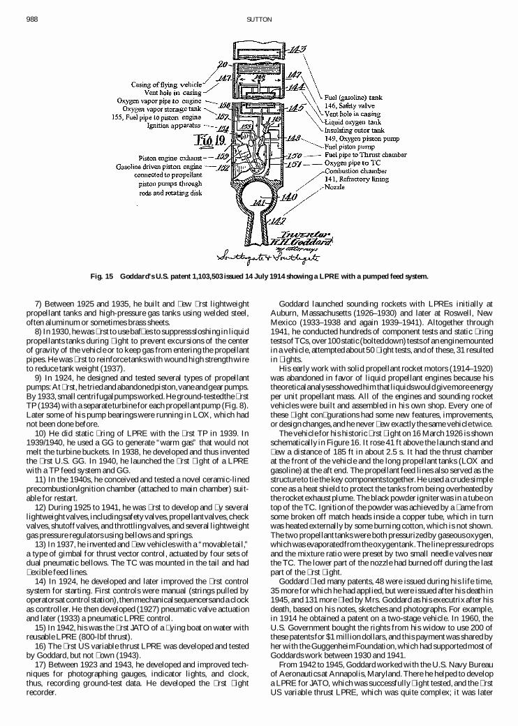
1) One of his patents gave the � rst plausibledrawing and descrip-tion of a LPRE with a pump feed system. The drawing is shown inFig. 15 (1914).
2) Between 1921 and 1925, he designed, developed, and groundtested the � rst liquid propellant thrust chambers. Initial thrust levelswere between 40 to 100 lbf for a 1.0 in.-diam chamber (Fig. 1).Later he built 5-, 6-, and 10-in.-diam chambers with up to 1000-lbfthrust. He used LOX as the oxidizer, initiallywith ether as a fuel. Hethen tested gasoline, alcohol and kerosene with LOX. Early nozzleswere long and had an exit cone half-angleof 4–5 deg; he used largernozzle half angle after 1941.
3) From 1924 to 1930, using a “curtain � ow,” a type of � lm cool-ing, he achieved� ring durationof more than 1 min without burnout.In 1943, he adopted regenerative cooling, which was invented byothers.
4) He used black powder igniter (1923) and then pioneered py-rotechnic igniter with solid propellant (1927) and spark plug igniter(1937) for restart.
5) From1921to 1923hedevelopedthe � rstpropellantfeedsystemusing high-pressuregas to expel liquid propellants from their tanksand into a thrust chamber. He later included valves or ori� ces toadjust line pressure drops for best mixture ratio and � ows.
6) The � rst � ight of an LPRE in the world on 16 March 1926 wasaccomplished by him (described later).
988 SUTTON
Fig. 15 Goddard’s U.S. patent 1,103,503 issued 14 July 1914 showing a LPRE with a pumped feed system.
7) Between 1925 and 1935, he built and � ew � rst lightweightpropellant tanks and high-pressure gas tanks using welded steel,often aluminum or sometimes brass sheets.
8) In 1930,he was � rst to use baf� es to suppress sloshing in liquidpropellants tanks during � ight to prevent excursions of the centerof gravity of the vehicle or to keep gas from entering the propellantpipes. He was � rst to reinforce tanks with wound high strengthwireto reduce tank weight (1937).
9) In 1924, he designed and tested several types of propellantpumps:At � rst, he triedand abandonedpiston,vane andgear pumps.By 1933, small centrifugalpumps worked.He ground-testedthe � rstTP (1934) with a separate turbine for each propellantpump (Fig. 8).Later some of his pump bearings were running in LOX, which hadnot been done before.
10) He did static � ring of LPRE with the � rst TP in 1939. In1939/1940, he used a GG to generate “warm gas” that would notmelt the turbine buckets. In 1938, he developed and thus inventedthe � rst U.S. GG. In 1940, he launched the � rst � ight of a LPREwith a TP feed system and GG.
11) In the 1940s, he conceived and tested a novel ceramic-linedprecombustion/ignition chamber (attached to main chamber) suit-able for restart.
12) During 1925 to 1941, he was � rst to develop and � y severallightweightvalves, includingsafetyvalves,propellantvalves,checkvalves, shutoffvalves, and throttlingvalves, and several lightweightgas pressure regulators using bellows and springs.
13) In 1937, he invented and � ew vehicles with a “movable tail,”a type of gimbal for thrust vector control, actuated by four sets ofdual pneumatic bellows. The TC was mounted in the tail and had� exible feed lines.
14) In 1924, he developed and later improved the � rst controlsystem for starting. First controls were manual (strings pulled byoperatorsat controlstation),thenmechanicalsequencersanda clockas controller. He then developed (1927) pneumatic valve actuationand later (1933) a pneumatic LPRE control.
15) In 1942, his was the � rst JATO of a � ying boat on water withreusable LPRE (800-lbf thrust).
16) The � rst US variable thrust LPRE was developed and testedby Goddard, but not � own (1943).
17) Between 1923 and 1943, he developed and improved tech-niques for photographing gauges, indicator lights, and clock,thus, recording ground-test data. He developed the � rst � ightrecorder.
Goddard launched sounding rockets with LPREs initially atAuburn, Massachusetts (1926–1930) and later at Roswell, NewMexico (1933–1938 and again 1939–1941). Altogether through1941, he conducted hundreds of component tests and static � ringtestsofTCs, over100static(bolteddown) testsofan enginemountedin a vehicle, attempted about50 � ight tests, and of these, 31 resultedin � ights.
His early work with solid propellant rocket motors (1914–1920)was abandoned in favor of liquid propellant engines because histheoreticalanalysesshowedhim that liquidswouldgivemore energyper unit propellant mass. All of the engines and sounding rocketvehicles were built and assembled in his own shop. Every one ofthese � ight con� gurations had some new features, improvements,or design changes,and he never � ew exactly the same vehicle twice.
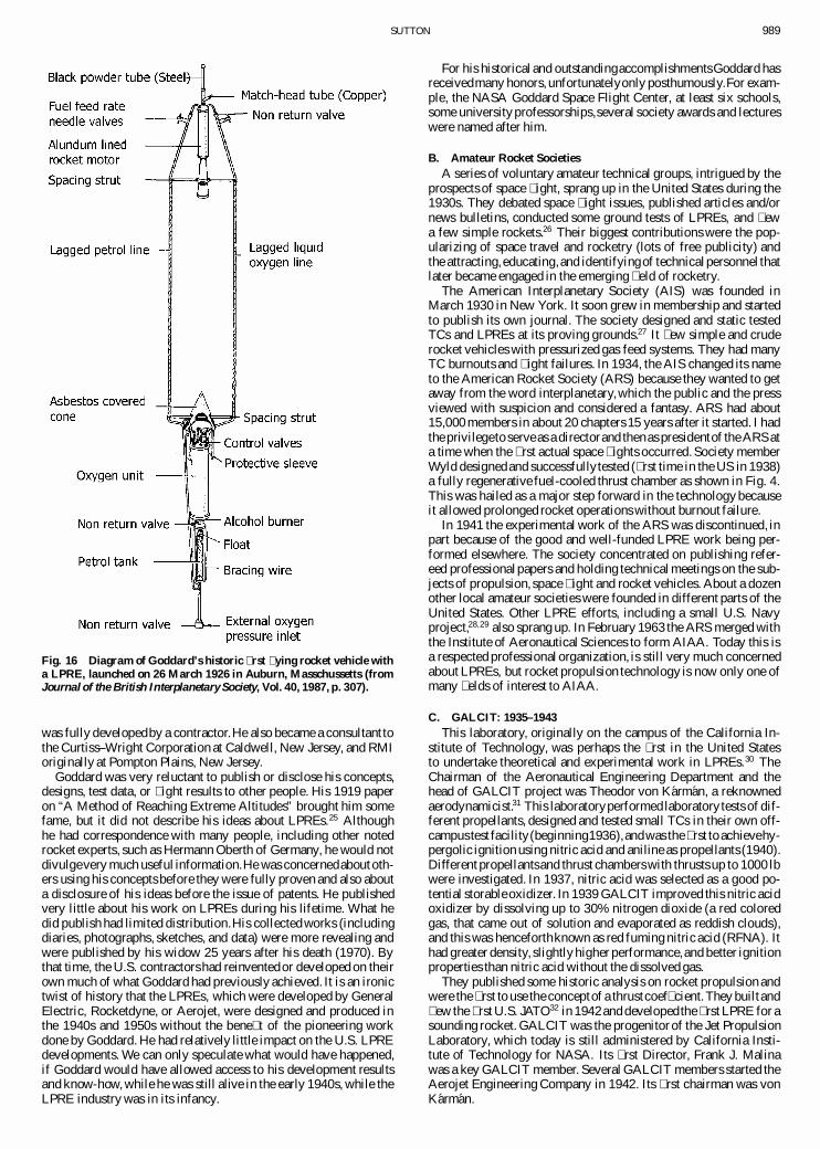
The vehicle for his historic � rst � ight on 16 March 1926 is shownschematically in Figure 16. It rose 41 ft above the launch stand and� ew a distance of 185 ft in about 2.5 s. It had the thrust chamberat the front of the vehicle and the long propellant tanks (LOX andgasoline) at the aft end. The propellant feed lines also served as thestructure to tie the key components together.He used a crude simplecone as a heat shield to protect the tanks from being overheated bythe rocket exhaust plume. The black powder igniter was in a tube ontop of the TC. Ignition of the powder was achieved by a � ame fromsome broken off match heads inside a copper tube, which in turnwas heated externally by some burning cotton, which is not shown.The two propellant tanks were both pressurizedby gaseousoxygen,which was evaporatedfrom theoxygentank.The line pressuredropsand the mixture ratio were preset by two small needle valves nearthe TC. The lower part of the nozzle had burned off during the lastpart of the � rst � ight.
Goddard � led many patents, 48 were issued during his life time,35 more for which he had applied, but were issued after his death in1945, and 131 more � led by Mrs. Goddard as his executrixafter hisdeath, based on his notes, sketches and photographs. For example,in 1914 he obtained a patent on a two-stage vehicle. In 1960, theU.S. Government bought the rights from his widow to use 200 ofthese patents for $1 million dollars, and this payment was shared byher with the GuggenheimFoundation,which had supportedmost ofGoddards work between 1930 and 1941.
From 1942 to 1945, Goddard worked with the U.S. Navy Bureauof Aeronautics at Annapolis, Maryland.There he helped to developa LPRE for JATO, which was successfully� ight tested, and the � rstUS variable thrust LPRE, which was quite complex; it was later
SUTTON 989
Fig. 16 Diagram of Goddard’s historic � rst � ying rocket vehicle witha LPRE, launched on 26 March 1926 in Auburn, Masschussetts (fromJournal of the British Interplanetary Society, Vol. 40, 1987, p. 307).
was fully developedby a contractor.He also became a consultant tothe Curtiss–Wright Corporation at Caldwell, New Jersey, and RMIoriginally at Pompton Plains, New Jersey.
Goddard was very reluctant to publish or disclose his concepts,designs, test data, or � ight results to other people. His 1919 paperon “A Method of Reaching Extreme Altitudes” brought him somefame, but it did not describe his ideas about LPREs.25 Althoughhe had correspondence with many people, including other notedrocket experts, such as Hermann Oberth of Germany, he would notdivulgevery much useful information.He was concernedaboutoth-ers using his concepts before they were fully proven and also abouta disclosure of his ideas before the issue of patents. He publishedvery little about his work on LPREs during his lifetime. What hedid publish had limited distribution.His collected works (includingdiaries, photographs, sketches, and data) were more revealing andwere published by his widow 25 years after his death (1970). Bythat time, the U.S. contractorshad reinventedor developed on theirown much of what Goddard had previously achieved. It is an ironictwist of history that the LPREs, which were developed by GeneralElectric, Rocketdyne, or Aerojet, were designed and produced inthe 1940s and 1950s without the bene� t of the pioneering workdone by Goddard. He had relatively little impact on the U.S. LPREdevelopments. We can only speculate what would have happened,if Goddard would have allowed access to his development resultsand know-how, while he was still alive in the early 1940s, while theLPRE industry was in its infancy.
For his historical and outstandingaccomplishmentsGoddard hasreceivedmany honors, unfortunatelyonly posthumously.For exam-ple, the NASA Goddard Space Flight Center, at least six schools,some universityprofessorships,several society awards and lectureswere named after him.
B. Amateur Rocket SocietiesA series of voluntary amateur technical groups, intrigued by the
prospects of space � ight, sprang up in the United States during the1930s. They debated space � ight issues, published articles and/ornews bulletins, conducted some ground tests of LPREs, and � ewa few simple rockets.26 Their biggest contributions were the pop-ularizing of space travel and rocketry (lots of free publicity) andthe attracting,educating,and identifyingof technicalpersonnel thatlater became engaged in the emerging � eld of rocketry.
The American Interplanetary Society (AIS) was founded inMarch 1930 in New York. It soon grew in membership and startedto publish its own journal. The society designed and static testedTCs and LPREs at its proving grounds.27 It � ew simple and cruderocket vehicles with pressurized gas feed systems. They had manyTC burnouts and � ight failures. In 1934, the AIS changed its nameto the American Rocket Society (ARS) because they wanted to getaway from the word interplanetary,which the public and the pressviewed with suspicion and considered a fantasy. ARS had about15,000 members in about 20 chapters 15 years after it started. I hadthe privilegeto serve as a directorand thenas presidentof the ARS ata time when the � rst actual space � ights occurred. Society memberWyld designedand successfullytested (� rst time in the US in 1938)a fully regenerative fuel-cooled thrust chamber as shown in Fig. 4.This was hailed as a major step forward in the technology becauseit allowed prolonged rocket operations without burnout failure.
In 1941 the experimental work of the ARS was discontinued, inpart because of the good and well-funded LPRE work being per-formed elsewhere. The society concentrated on publishing refer-eed professionalpapers and holding technical meetings on the sub-jects of propulsion, space � ight and rocket vehicles. About a dozenother local amateur societies were founded in different parts of theUnited States. Other LPRE efforts, including a small U.S. Navyproject,28;29 also sprang up. In February 1963 the ARS merged withthe Institute of Aeronautical Sciences to form AIAA. Today this isa respected professional organization, is still very much concernedabout LPREs, but rocket propulsion technology is now only one ofmany � elds of interest to AIAA.
C. GALCIT: 1935–1943This laboratory, originally on the campus of the California In-
stitute of Technology, was perhaps the � rst in the United Statesto undertake theoretical and experimental work in LPREs.30 TheChairman of the Aeronautical Engineering Department and thehead of GALCIT project was Theodor von Karman, a reknownedaerodynamicist.31 This laboratoryperformed laboratorytests of dif-ferent propellants, designed and tested small TCs in their own off-campustest facility(beginning1936),andwas the � rst to achievehy-pergolic ignition using nitric acid and aniline as propellants (1940).Different propellantsand thrust chambers with thrusts up to 1000 lbwere investigated. In 1937, nitric acid was selected as a good po-tential storableoxidizer. In 1939 GALCIT improved this nitric acidoxidizer by dissolving up to 30% nitrogen dioxide (a red coloredgas, that came out of solution and evaporated as reddish clouds),and this was henceforthknown as red fuming nitric acid (RFNA). Ithad greater density, slightlyhigher performance,and better ignitionproperties than nitric acid without the dissolved gas.
They published some historic analysis on rocket propulsion andwere the � rst to use the conceptof a thrustcoef� cient.They builtand� ew the � rst U.S. JATO32 in 1942and developedthe � rst LPRE for asounding rocket. GALCIT was the progenitor of the Jet PropulsionLaboratory, which today is still administered by California Insti-tute of Technology for NASA. Its � rst Director, Frank J. Malinawas a key GALCIT member. Several GALCIT members started theAerojet Engineering Company in 1942. Its � rst chairman was vonKarman.
990 SUTTON
V. LPRE Industry in the USA: 1941–2003A. Innovations and Accomplishments
A list follows of signi� cant and historic U.S. industrial achieve-ments and key events in this � eld. This list is not complete or in anyparticular order.
1) The demands for new technologyand missile productionwerevery high during the cold war with the Soviet Union during the1950–1970 period, and the U.S. LPRE industry successfully metthese demands and did its share to put missiles into the arsenal.
2) In 1965, the United States launched Saturn V with the high-est thrust engine at that time, namely, a cluster of � ve F-1 LPREsat 1:5 £ 106-lb thrust each. This record stood until 1985 when theSoviets � ew a somewhat larger engine. The 1:8 £ 106-lb of the ex-perimentalF-1A is the highest known thrust of a LPRE ground test.
3) There were a good number of inventions, innovations, or � rstimplementationsof technologythat can be credited to organizationsin the United States. This includes the � rst � ight of an engine withliquid hydrogenas a fuel, the � rst expanderengine cycle, the theoryof bell-shaped nozzles, the � rst TP, the � rst booster pump, the � rstexpander engine cycle engine, and the � rst applications of gimbalsto TCs for thrust vector control (TVC) (1947). Furthermore, therewas the developmentof the tubular thrust chambers for regenerativecooling, the � rst use of ablativeson LPREs, the developmentof spe-cial materials for the hot-TC walls and for turbine buckets, � at platemachined injectors made of forgings, certain clever valve designs,certain injection patterns,Aerojet’s platelet injectors, the electronicengine controls, pressurizing propellant tanks with gas generators,variablepositionpintle injectors,� rst � ight of an extendiblenozzle,� rst applicationof liquid side injection for TVC, and very fast smallpropellant valves mounted on an injector of a small thruster.
4) There are a number of clever innovations that were conceivedand implementedwith pride in the United States, but very similar in-novationswere actually accomplishedat an earlier date in Germanyand/or the Soviet Union. The LPRE work in these two countrieswassecret and advancedat the time and not known to U.S. LPRE person-nel until years later. Examples include the staged combustion cycle,the use of inducer impellersaheadof the main pump impellers,earlyreinforced concrete test facilities, the highest thrust large � ying en-gine, earliest LPREs speci� cally for aircraft installation, the � rstairplane � ights with LPREs, prepackagedLPREs with storablepro-pellants, or TVC by auxiliary or vernier thrust chambers suppliedby the main engine feed system. It also includes a large LPRE withthe highest chamber pressure and pump-fed experimental LPREswith certain high-energy propellants.
5) The RL-10B2 of Pratt and Whitney is the � rst pump-fedLOX/LH2 engine that has � own (in 2000) with the highest knownspeci� c impulse, namely, 467 s. It was the � rst � ight applicationofan extendible nozzle exit segment with a LPRE.
6) The United States had in 1965a small radiationcooled thrusterthat could demonstrate over 100,000 cycles or restarts, a record atthe time.
7) Several of the propellantsoriginated in the United States. Thisprobably includes RFNA, inhibitedRFNA, Aerozine 50, mixed ox-idesof nitrogen,gelledpropellants,hydroxylammoniumnitrate,andultrapure hydrazine that would not contaminate its catalysts.
8) The United States was a leader in the applicationof computersand software to LPREs. Computers became part of the controlsfor LPRE beginning in the 1970s. The Rocketdyne RS-68 was the� rst LPRE to be fully designed by computers in the 1990s. Thiscovers not only design or analysis programs, but also integrationwith manufacturing, test operations, engine controllers, cost andschedulecontrol,spareparts inventory,testdata reductionor display,and other areas.
9) The Nike –Ajax antiaircraftmissile used a LPRE for the upperstage, and it was the � rst such military air defense system to bedeployed for this purpose.
10) The United States has probably built more different JATOLPREs than any other country.
11) The production of 50,000 Bullpup engines was a unique ac-complishment; it represents the largest number of LPREs ever pro-duced anywhere.
12) The Lance TC con� guration with the sustainer TC inside theannular booster TC is novel and compact, and the use of liquid pro-pellant side injection for TVC is unique. The highest known thrustvariation of 300 to 1 (from 4400 down to 14 lb) was achieved in theLance sustainer TC assembly. It is discussed further in Sec. V.B.3.
B. Companies in This BusinessSince the 1940s at least 14 U.S. companies have engaged in the
design, development,manufacture, testing, and � ight support oper-ations of some types of LPRE. Table 3 lists their names (roughly inthe order of the years of their start) and shows that there have beenmergers and consolidation.Most of these companies have gone outof the LPRE business, were acquired, or merged. Today there are� ve that are active at the time of this writing, and each will be brie� ydiscussed. In the book currentlybeing written, there are discussionsof LPREs of all of the 14 listedcompanies.There were other compa-nies, but they are not shown in Table 3. They includeaerospacecom-panies and subsystem suppliers, where the development of LPREswas a sporadic or sideline activity. None of their engines has as yetresulted in a production. The data in this section come from theauthor’s recollection and from personal communications.
Employment in the LPRE business was high between 1955 and1968 during the cold war period and historically the busiest timein the LPRE industry. The real funding available to LPREs hassince decreased, as have the number of employees and the numberof companies. For example, the peak total LPRE employment atRocketdyne was about 20,000 people in 1964; it hit a low in 1971but went up to about 5500 in 1985 and was about 2800 in 2001.Aerojet’s employment in LPREs personnel peaked in 1963 at about10,000 and was about 1000 in the year 2000.
Although some good research and development(R&D) work hasbeen done in the United States by certain universities, some privateresearch organizations, and by government laboratories, they arenot discussedhere because they did not develop and qualify LPREsthat went into production or became operational. This includes forexample R&D work at Princeton University, Cornell University,Purdue University, Pennsylvania State University, University ofAlabama, Naval Postgraduate School, and California Institute ofTechnology.The graduateand undergraduateeducationof quali� edtechnical LPRE personnel is perhaps the universities’ most impor-tant contribution,and more than25U.S. universitieshave at one timetaught courses concerned with LPREs. Research organizationsthathave worked on LPRE issues include Batelle Memorial Institute,The Aerospace Corporation, and SRI (formerly Stanford ResearchInstitute). Government organizations doing or having done workon LPRE includes the Rocket Propulsion Laboratory (now part ofPhilips Laboratory of the U.S. Air Force) at Edwards Air ForceBase, Edwards, California, the U.S. Air Force Arnold EngineeringTest Center, at Tullahoma, Tennesee, NASA Marshall Space FlightCenter at Huntsville, Alabama, NASA-funded Jet Propulsion Lab-oratory in Pasadena, California, NASA Stennis Space Center inMississippi, and NASA John H. Glenn Research Center at LewisField, Cleveland, Ohio. These and other government organizationsare indeed useful in testing LPREs and de� ning, selecting, funding,guiding, and monitoring work at U.S. companies, doing R&D andtesting, and in providing propellants, testing facilities/services forlarge and small LPREs, hover test facilities, or simulated altitudetest facilities.
1. Reaction Motors, Inc. (RMI)RMI was the � rst American LPRE company.32¡34 It was founded
by four amateur experimentersof the American Rocket Society andincorporatedin August of 1941. The words rocket motor were usedin those days for what today is designated as a rocket engine. In1958, RMI was acquired by and became a division of Thiokol Cor-poration, a manufacturerof solid propellant rocket motors. In 1972the Reaction Motor Division was shut down and ceased operationsdue to a lack of business. Because of the limit on the length of thissummary, only two of their historic LPREs will be discussed.
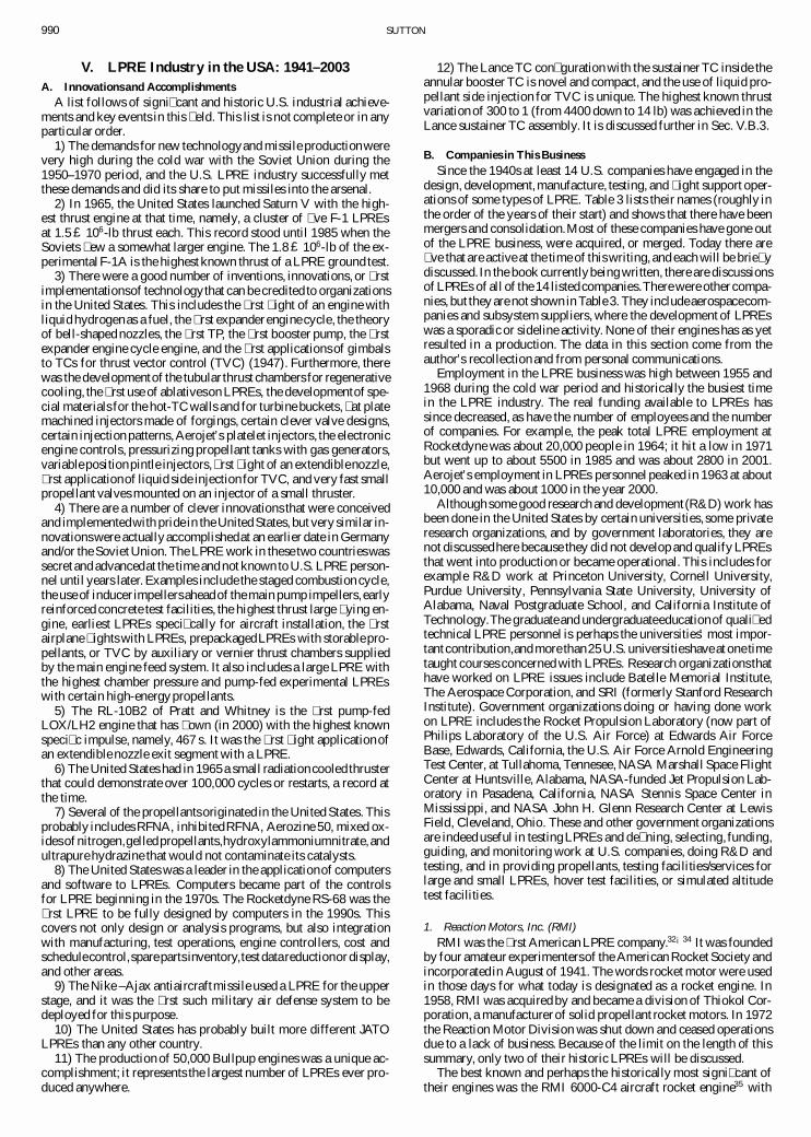
The best known and perhaps the historically most signi� cant oftheir engines was the RMI 6000-C4 aircraft rocket engine35 with
SUTTON 991
Table 3 U.S. companies in the LPRE Business (1941–2002)
Company Typical LPRE work Comments
RMI Engines for experimental aircraft, Started Dec. 1941,Viking, prepackaged, vernier merged into Thiokol 1958,reaction control thrusters stopped operating 1972
Aerojet All types of LPRE Started in 1942, bought by General Tirewas Aerojet Engineering Corporation, 1944, spun off as GeneralCorporation Corporation, bought General Dynamics
propulsion operation 2002Curtiss-Wright Corporation LPRE for research aircraft 1943–1960a Work stoppedGeneral Electric Company Hermes and V-2 operation, 1944–1967a
(Rocket Section) Vanguard booster Section was dissolvedRocketdyne Propulsion All types of LPRE Started 1945 as part of North
and Power, since 1996 a American Aviation, merged intopart of The Boeing Company Rockwell International Corporation 1964
Walter Kidde & Company H2O2 monopropellant 1945–1958a Work stoppedARC Agena upper stage, small Formerly Bell Aircraft Company
Liquid Division. attitude control LPRE started LPREs in 1947,became division of Sequa Corporation bought Royal Ordnance 1997
Acquired hydrazine monopropellantline from Marquard 2001(originally Hamilton Standard)
M. W. Kellogg Company JATO units 1945–1953a Work stoppedPratt and Whitney, a United Upper stage LOX/LH2 Started 1957/1958
Technologies Company LPREs, Russian RD 180Marquard Corporation, became Small bipropellant LPRE Started LPRE 1958, bought by Kaiser
Kaiser–Marquard, 1990 or reaction control systems 1990, bought hydrazine TC lineSold to Primex 2001 from Hamilton Standard, in 1996
Northrop Grumman Corporation Attitude control LPRE, Started 1960 as part of SpacePropulsion Products Center lunar lander and others Technology Laboratory, name TRWformerly TRW, Inc. adopted in 1965, bought by
Northrup Grumman 2003Rocket Research Corporation Hydrazine monopropellant Started LPREs in 1963,
spun off as Primex, 1996 TCs and aquired by Olin Corporation 1985,bought by General bipropellant TC (in 2000) Primex bought Kaiser–Dynamics Corporation in 2001 Marquardt in 2000
Hamilton Standard Division Hydrazine monopropellant Started 1964, technologyUnited Technologies thrust chambers bought by Marquardt in 1995,Corporation (small group) divested to ARC in 2001
General Dynamics Corporation (GD) All types of small TCs Bought Primex in 2001ACS/maneuver systems sold to Aerojet in 2002
aDate is not con� rmed.
four fuel-cooled thrust chambers shown in Fig. 17. It was designedfor the Bell Aircraft manned-research airplane X-1. This enginepropelled this aircraft on 14 October 1947 to a record speed ofMach 1.06. The engine had four thrust chambers at 1500 lbf each(total 6000 lbf) with LOX/75% alcohol at a chamber pressure of220 psia and a speci� c impulse (sea level) of 209 s. The initialversions � ew with a pressurized feed system. Later versions had aTP feed system with a GG supplied with hydrogen peroxide,whichwas decomposed by a catalyst; the propellant tank pressures andtotal propulsion system weights were lower. Each thrust chamberhad a small igniter chamber in the center of the injector designedto allow multiple starts. The igniter used a spark plug to ignite asmall � ow of fuel and gaseous oxygen that had been evaporatedin coils around the fuel feed pipe. The engine was improved andused to � y several later versions of the Bell X-1 research aircraft,the Douglas D558-2 Skyrocket research aircraft, several unmannedresearch lifting bodies, and as a dual engine for an interim powerplant for the North American X-15 research airplane. An up-ratedversion of this four-barrel engine (at 435-psi chamber pressure and7600–8400 lb total thrust) launched the small scale model of theNavaho missile (Project MX-774), but without restart capability.It was the � rst U.S. engine with hinged thrust chambers, whichallowed � ightpath control. There were engine-related problems intwo of the three � ights.
RMI developed several storable propellant prepackaged rocketpropulsionsystems. In the 1940sand 1950s, solidpropellantmotorshad problems operating at ambient temperatures lower than about¡40±F, but the liquid engines could meet the required minimum
Table 4 Bullpup LPRE data
Engine designation LR58 or Bullpup A LR62 or Bullpup B
Diameter, in. (cm) 12.1 (102.7) 17.3 (43.9)Length, in. (cm) 40.5 (102.7) 61.2 (155.4)Weight, loaded, lb (kg) 203 (92.3) 563 (255.3)Weight, dry, lb (kg) 92 (41.8) 205 (92.9)Thrust, lbf (kN) 12,000 (52.8) 30,000 (132)Duration, s 1.9 2.3Total impulse, lb ¢ s (kN ¢ s) 22,800 (101) 69,000 (307)
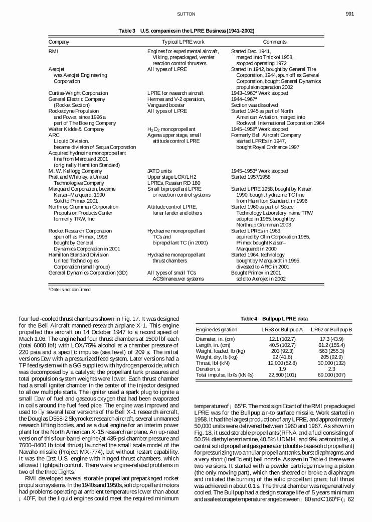
temperatureof¡65±F. The most signi� cant of the RMI prepackagedLPRE was for the Bullpup air-to surface missile. Work started in1958. It had the largest productionof any LPRE, and approximately50,000 units were delivered between 1960 and 1967. As shown inFig. 18, it used storable propellants (RFNA and a fuel consistingof50.5% diethylenetriamine, 40.5% UDMH, and 9% acetonitrile), acentral solid propellantgas generator (double-basesolid propellant)for pressurizingtwo annularpropellanttanks,burstdiaphragms,anda very short (inef� cient) bell nozzle. As seen in Table 4 there weretwo versions. It started with a powder cartridge moving a piston(the only moving part), which then sheared or broke a diaphragmand initiated the burning of the solid propellant grain; full thrustwas achieved in about 0.1 s. The thrust chamber was regenerativelycooled. The Bullpup had a design storage life of 5 years minimumanda safestoragetemperaturerangebetween¡80andC160±F(¡62
992 SUTTON
Fig. 17 RMI 6000C-4 LPRE for research aircraft with four TCs; each could be turned on or off individually,thus, giving a stepwise change in thrust(from Ref. 3).
Fig. 18 Cutaway section of the Bullpup A (LR-58) (from Ref. 34, Part III, 1983).
and C71±C). Bullpup became an operationalmissile in 1959. Therewere thousands of test � rings, both on the test stand and in � ight.Reliability was rated at 0.9972. Military cutbacks and changingmilitary requirementseventually caused the Bullpup to be taken outof service.
2. Aerojet General CorporationThis company (originally known as Aerojet Engineering Com-
pany) is commonly called “Aerojet”; it is a subsidiary unit of Gen-
Corp, Inc. It was the second U.S. company dedicated to rocketpropulsion,was started 1942, and it grew quickly.36¡38 It was men-tioned in Sec. IV.C to havebeen a direct outgrowthof rocketpropul-sion projects done earlier at the GALCIT under the guidance ofvon Karman, a famous aerodynamicist.31 For several decades, thework on LPREs represented about one-quarter of Aerojet’s busi-ness. Aerojet was also engaged in solid propellant rocket propul-sion, nuclear propulsion, ordnance, and other areas. In August of2002 Aerojet acquired the rocket propulsionassets,LPRE products,
SUTTON 993
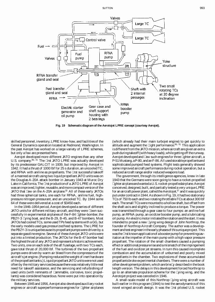
Fig. 19 Schematic diagram of the Aerotojet LPRE concept (courtesy Aerojet).
skilled personnel, inventory, LPRE know-how, and facilities of theGeneral Dynamics operation located at Redmond, Washington. Inthe past Aerojet has worked on a large variety of LPRE schemes,but only a few are presented here.
Aerojet developed more different JATO engines than any otherU.S. company.36¡41 The � rst JATO LPRE was actually developedby its predecessor GALCIT in 1939, but improved by Aerojet in1942. It had a thrust of 1000 lbf for 25 s duration, an uncooled TC,and RFNA with aniline as propellants. The � rst successful takeoffof a manned aircraft using two liquid propellant JATO units was onthe Douglas A-20A attack bomber in January 1943 at Muroc DryLake in California.The � rst productionof a JATO LPRE of Aerojetwas an improved, lighter, reusable,and more compact versionof theJATO that � ew on the A-20A airplane.32 All of these early JATOshad three spherical tanks, one each for RFNA, aniline fuel, high-pressure nitrogen pressurant, and an uncooled TC. By 1944 some64 of these were delivered at a cost of $3450 each.
In the 1946–1954 period, Aerojet developed a series of differentJATO units for different military aircraft, and they were � own suc-cessfully in experimental airplanes of the F-84 � ghter-bomber, thePB2Y-3 � ying boat, and the B-29, B-45, and B-47 bombers. MostJATOs had cooled TCs, some used TPs feed systems with a GG, butthe early models used gas pressurized feed systems. The LPRE forthe PB2Y-3 is unique because its propellantpumps were driven by aseparate gasoline engine. Several of these Aerojet JATO units wereput into a limited production. The JATOs for the B-47 bomber hadthe highest thrust of any JATO and representa historic achievement.Two units, one on each side of the aft fuselage, with two TCs each,gave total thrust of 20,000 lbf. The turbines of the two propellantpumps were driven by warm air bleed from the compressors of theaircraft’s jet engine. (Pumping reduced the weight of inert hardwareof the propellant tanks.)Liquid propellantJATO units were not usedoften by the military services because there was relatively little realneed for takeoff assistance, and the servicing and refurbishing ofused units (with remnants of � ammable, corrosive, toxic propel-lants) was considered hazardous. None were put into operation bythe military services.
Between 1945 and 1956, Aerojet also developedauxiliary rocketengines or aircraft superperformance engines for � ghter airplanes
(which already had their main turbojet engine) to get quickly toaltitude and augment the � ight performance.36¡41 This applicationis differentfrom the JATO mission,where aircraft are given an extrapushduring takeoff(withheavy loads),while gettingoff the runway.Aerojet developedand � ew such engines for three � ghter aircraft, aP-51 Mustang,a P-80, and anF-86.All usedstorablepropellantsandsophisticated pumped feed systems. Flight tests generally showedsome improved aircraft performance during rocket operation, but areduced aircraft range and/or reduced weapons load.
The government, through its intelligence agencies, knew in late1943 that the Germans were soon going to have a rocket-propelled� ghterairplaneandwanteda U.S. rocket-propelledairplane.Aerojetconceived,designed, built, and partially tested a very unique LPREfor an aircraft power plant, called the Aerotojet,37 and it was quicklyputundercontract in 1944.As shown in Fig. 19, it had two stationaryTCs of 750 lb each and two rotating throttlableTCs at about 300 lbfeach.The small TCs were mounted to a hollow shaft, but offset fromthe shaft axis and slightly inclined to produce a torque. The powerwas transmitted through a gear case to four pumps: an aniline fuelpump, an RFNA pump, an oxidizerbooster pump, and a lubricatingoil pump. An electricmotor initiatedthe rotationand the start. It wasintended to propel a new � ying wing design of John Northrop, thefounder of Northrop Aircraft Company. The author was a develop-ment and test engineerin the earlyphasesof thisuniqueproject.Thiswas the � rst knownapplicationof a boosterpumpforpreventingcav-itation at the impeller of the main pump with a high vapor pressurepropellant. The rotation of the small chambers caused a pumpingeffect or additionalpressurerise and a mismatchof the impingementof the fuel and oxidizer jet streams. In turn this caused incompletecombustion and the accumulation of unburned and poorly mixedpropellants in the chamber. Two explosions of these accumulatedpropellants broke experimental chambers. There were a number ofother developmentproblem, which are brie� y described in the booklength version. The delays in this development forced Northrop togo to an alternate propulsion scheme for the � ying wing, and theAerotojet project was canceled in 1946.
A small-scale model of this Northrop � ying wing aircraft wasbuilt earlier in this program (1944) to test the aerodynamics of thisnovel winged aircraft design. It was the � rst piloted U.S. rocket
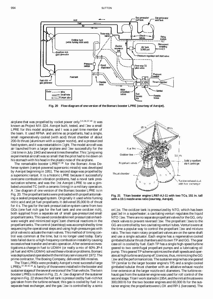
994 SUTTON
Fig. 20 Flow diagram of one version of the Bomarc booster LPRE (courtesy of Aerojet).
airplane that was propelled by rocket power only.3;5;36;37;40 It wasknown as Project MX-324. Aerojet built, tested, and � ew a smallLPRE for this model airplane, and I was a part time member ofthe team. It used RFNA and aniline as propellants, had a single,small regeneratively cooled (with acid) thrust chamber of about200-lb thrust (aluminum with a copper nozzle), and a pressurizedfeed system, and it was restartable in-� ight. The model aircraft wasair launched from a larger airplane and � ew successfully for the� rst time in July 1943 and several times thereafter.This � ying wingexperimental aircraft was so small that the pilot had to lie down onhis stomach with his head in the plastic nose of the airplane.
The remarkable booster LPRE37;38 for the Bomarc Area De-fense system (ramjet-powered supersonic missile) was developedby Aerojet beginning in 1951. The second stage was propelled bya supersonic ramjet. It is a historic LPRE because it successfullyovercame combustion vibration problems, had a novel tank pres-surization scheme, and was the � rst Aerojet LPRE to use a gim-baled uncooled TC (with a ceramic lining) in a military operation.A � ow diagram of one version of the Bomarc booster LPRE is inFig. 20. The propellant tanks were preloadedwith propellantsmak-ing a sealed prepackaged system. Originally it used white fumingnitric acid and jet fuel propellants. It delivered 35,000 lb of thrustfor 4 s. The gas for the tank pressurization system came from twoGGs (one fuel rich gas for the fuel tank and one oxidizer rich),both supplied from a separate set of small gas-pressurized smallpropellant tanks. This saved considerable inert pressurizationhard-ware weight and minimized signi� cant chemical reactions in thepropellant tanks. The control (start/stop) was accomplishedby timesequencing the operational steps and using high-pressure gas withpilot valves to actuate the main valves. This method of timing con-trol was common at the time, but is no longer used today. Earlytests failed due to a high-frequencycombustion instability causingexcessive heat transfer and erratic operation.After extensive inves-tigations a change in fuel to UDMH (or really a mix of 60% JP-4jet fuel and 40% UDMH) solved these vibration problems. Bomarcwas deployedand operatedwith themilitaryservicesuntil 1972.Theprime contractor,The Boeing Company, delivered 366 missiles.
The Titan LPREs were probably Aerojet’s most successful largeLPREs.37;38;42;43 A family of those were installed in the booster andsustainerstagesof the severalversionsof the Titan vehicle.The twinbooster LPREs is shown in Fig. 21. A � ow diagram of the sustainerengine in Fig. 22 shows the fuel tank is pressurizedby fuel-rich hotgas taken from the turbine exhaust; this gas is cooled by fuel in aseparate heat exchanger, and the gas � ow is controlled by a sonic
Fig. 21 Titan booster engine LR87-AJ-11 with two TCs, 151 in. tallwith a 15:1 nozzle area ratio (courtesy, Aerojet).
ori� ce. The oxidizer tank is pressurized by NTO, which has beengasi� ed in a superheater; a cavitating venturi regulates the liquidNTO � ow. There are no separate propellantvalves for the GG, onlycheck valves to prevent reversed � ow. The propellant � ows to theGG are controlled by two cavitating venturi tubes. Venturis were atthe time a popular way to control the propellant � ow and mixtureratio. The two main rotary propellant valves are on the same shaftand use a single actuator. Each engine has a regenerative cooledgimbaled tubular thrust chambers and its own TP and GG. The gearcase oil is cooled by fuel. Each TP has a single high-speed turbinegeared to two centrifugal propellant pumps and a lubricating oilpump. This geared TP scheme optimizes the shaft speeds and oper-ates at high turbine and pump ef� ciencies, thus, minimizing the GG� ow and the performanceloss. The sustainerengine has one gearedTP (similar to the larger booster engine’s TP) and a single cooledgimbaled tubular thrust chamber with an ablative exhaust nozzleliner extension at the larger nozzle exit diameters. The turbine ex-haust gas from the sustainer engine was used for roll control of thesecondstage.Titan I work startedin 1954,and the initial thrustswere300,000 lb for the two booster engines and 60,000 lb for the sus-tainer engine; the propellants were LOX and RP-1 (kerosene). The
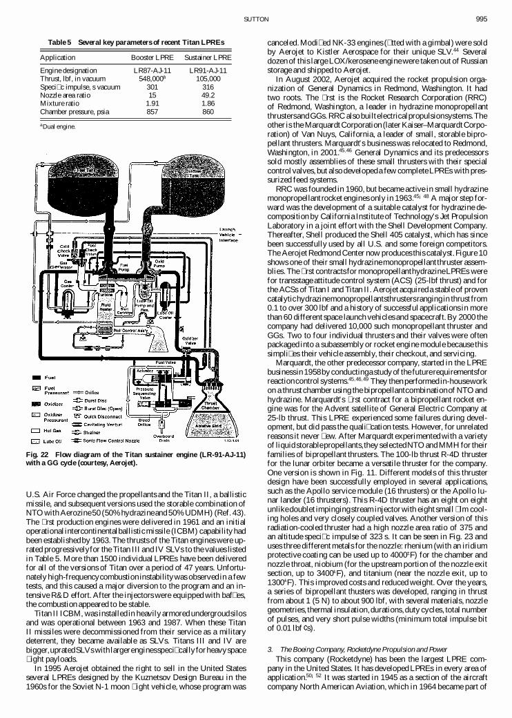
SUTTON 995
Table 5 Several key parameters of recent Titan LPREs
Application Booster LPRE Sustainer LPRE
Engine designation LR87-AJ-11 LR91-AJ-11Thrust, lbf, in vacuum 548,000a 105,000Speci� c impulse, s vacuum 301 316Nozzle area ratio 15 49.2Mixture ratio 1.91 1.86Chamber pressure, psia 857 860
aDual engine.
Fig. 22 Flow diagram of the Titan sustainer engine (LR-91-AJ-11)with a GG cycle (courtesy, Aerojet).
U.S. Air Force changed the propellants and the Titan II, a ballisticmissile, and subsequent versions used the storable combination ofNTO with Aerozine50 (50% hydrazineand 50% UDMH) (Ref. 43).The � rst production engines were delivered in 1961 and an initialoperationalintercontinentalballisticmissile (ICBM) capability hadbeen establishedby 1963. The thrusts of the Titan engines were up-rated progressivelyfor the Titan III and IV SLVs to the values listedin Table 5. More than 1500 individual LPREs have been deliveredfor all of the versions of Titan over a period of 47 years. Unfortu-nately high-frequencycombustion instabilitywas observed in a fewtests, and this caused a major diversion to the program and an in-tensive R&D effort. After the injectors were equipped with baf� es,the combustion appeared to be stable.
Titan II ICBM, was installed in heavily armored undergroudsilosand was operational between 1963 and 1987. When these TitanII missiles were decommissioned from their service as a militarydeterrent, they became available as SLVs. Titans III and IV arebigger,upratedSLVs with largerenginesspeci� callyforheavyspace� ight payloads.
In 1995 Aerojet obtained the right to sell in the United Statesseveral LPREs designed by the Kuznetsov Design Bureau in the1960s for the Soviet N-1 moon � ight vehicle, whose program was
canceled. Modi� ed NK-33 engines (� tted with a gimbal) were soldby Aerojet to Kistler Aerospace for their unique SLV.44 Severaldozen of this large LOX/kerosene engine were taken out of Russianstorage and shipped to Aerojet.
In August 2002, Aerojet acquired the rocket propulsion orga-nization of General Dynamics in Redmond, Washington. It hadtwo roots. The � rst is the Rocket Research Corporation (RRC)of Redmond, Washington, a leader in hydrazine monopropellantthrustersandGGs.RRC also builtelectricalpropulsionsystems.Theother is the MarquardtCorporation (later Kaiser–MarquardtCorpo-ration) of Van Nuys, California, a leader of small, storable bipro-pellant thrusters. Marquardt’s business was relocated to Redmond,Washington, in 2001.45;46 General Dynamics and its predecessorssold mostly assemblies of these small thrusters with their specialcontrolvalves, but also developeda few complete LPREs with pres-surized feed systems.
RRC was founded in 1960, but became active in small hydrazinemonopropellantrocket engines only in 1963.45¡48 A major step for-ward was the development of a suitable catalyst for hydrazine de-composition by California Institute of Technology’s Jet PropulsionLaboratory in a joint effort with the Shell Development Company.Thereafter, Shell produced the Shell 405 catalyst, which has sincebeen successfully used by all U.S. and some foreign competitors.The Aerojet Redmond Center now produces this catalyst.Figure 10shows one of their small hydrazinemonopropellant thruster assem-blies. The � rst contracts for monopropellanthydrazineLPREs werefor transstage attitude control system (ACS) (25-lbf thrust) and forthe ACSs of Titan I and Titan II. Aerojet acquireda stable of provencatalytichydrazinemonopropellantsthrustersrangingin thrust from0.1 to over 300 lbf and a history of successful applications in morethan 60 different space launch vehicles and spacecraft.By 2000 thecompany had delivered 10,000 such monopropellant thruster andGGs. Two to four individual thrusters and their valves were oftenpackaged into a subassembly or rocket engine module because thissimpli� es their vehicle assembly, their checkout, and servicing.
Marquardt, the other predecessor company, started in the LPREbusinessin 1958byconductinga studyof the futurerequirementsforreactioncontrol systems.45;46;49 They then performed in-houseworkon a thrust chamber using the bipropellantcombinationof NTO andhydrazine. Marquardt’s � rst contract for a bipropellant rocket en-gine was for the Advent satellite of General Electric Company at25-lb thrust. This LPRE experienced some failures during devel-opment, but did pass the quali� cation tests. However, for unrelatedreasons it never � ew. After Marquardt experimented with a varietyof liquid storablepropellants,they selectedNTO and MMH for theirfamilies of bipropellant thrusters. The 100-lb thrust R-4D thrusterfor the lunar orbiter became a versatile thruster for the company.One version is shown in Fig. 11. Different models of this thrusterdesign have been successfully employed in several applications,such as the Apollo service module (16 thrusters) or the Apollo lu-nar lander (16 thrusters). This R-4D thruster has an eight on eightunlikedoublet impingingstream injectorwith eight small � lm cool-ing holes and very closely coupled valves. Another version of thisradiation-cooled thruster had a high nozzle area ratio of 375 andan altitude speci� c impulse of 323 s. It can be seen in Fig. 23 anduses three different metals for the nozzle: rhenium (with an iridiumprotective coating can be used up to 4000±F) for the chamber andnozzle throat, niobium (for the upstream portion of the nozzle exitsection, up to 3400±F), and titanium (near the nozzle exit, up to1300±F). This improved costs and reduced weight. Over the years,a series of bipropellant thusters was developed, ranging in thrustfrom about 1 (5 N) to about 900 lbf, with several materials, nozzlegeometries, thermal insulation,durations,duty cycles, total numberof pulses, and very short pulse widths (minimum total impulse bitof 0.01 lbf ¢ s).
3. The Boeing Company, Rocketdyne Propulsion and PowerThis company (Rocketdyne) has been the largest LPRE com-
pany in the United States. It has developed LPREs in every area ofapplication.50¡52 It was started in 1945 as a section of the aircraftcompany North American Aviation, which in 1964 became part of
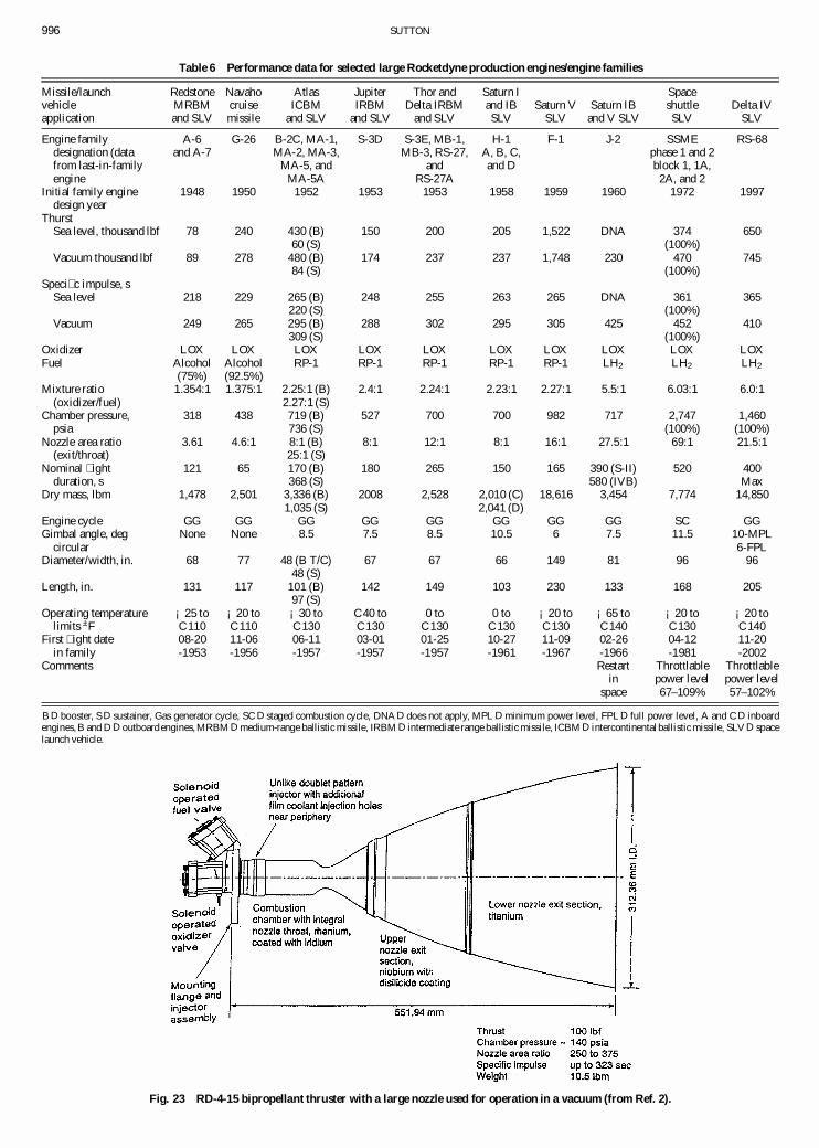
996 SUTTON
Table 6 Performance data for selected large Rocketdyne production engines/engine families
Missile/launch Redstone Navaho Atlas Jupiter Thor and Saturn I Spacevehicle MRBM cruise ICBM IRBM Delta IRBM and IB Saturn V Saturn IB shuttle Delta IVapplication and SLV missile and SLV and SLV and SLV SLV SLV and V SLV SLV SLV
Engine family A-6 G-26 B-2C, MA-1, S-3D S-3E, MB-1, H-1 F-1 J-2 SSME RS-68designation (data and A-7 MA-2, MA-3, MB-3, RS-27, A, B, C, phase 1 and 2from last-in-family MA-5, and and and D block 1, 1A,engine MA-5A RS-27A 2A, and 2
Initial family engine 1948 1950 1952 1953 1953 1958 1959 1960 1972 1997design year
ThurstSea level, thousand lbf 78 240 430 (B) 150 200 205 1,522 DNA 374 650
60 (S) (100%)Vacuum thousand lbf 89 278 480 (B) 174 237 237 1,748 230 470 745
84 (S) (100%)Speci� c impulse, s
Sea level 218 229 265 (B) 248 255 263 265 DNA 361 365220 (S) (100%)
Vacuum 249 265 295 (B) 288 302 295 305 425 452 410309 (S) (100%)
Oxidizer LOX LOX LOX LOX LOX LOX LOX LOX LOX LOXFuel Alcohol Alcohol RP-1 RP-1 RP-1 RP-1 RP-1 LH2 LH2 LH2
(75%) (92.5%)Mixture ratio 1.354:1 1.375:1 2.25:1 (B) 2.4:1 2.24:1 2.23:1 2.27:1 5.5:1 6.03:1 6.0:1
(oxidizer/fuel) 2.27:1 (S)Chamber pressure, 318 438 719 (B) 527 700 700 982 717 2,747 1,460
psia 736 (S) (100%) (100%)Nozzle area ratio 3.61 4.6:1 8:1 (B) 8:1 12:1 8:1 16:1 27.5:1 69:1 21.5:1
(exit/throat) 25:1 (S)Nominal � ight 121 65 170 (B) 180 265 150 165 390 (S-II) 520 400
duration, s 368 (S) 580 (IVB) MaxDry mass, lbm 1,478 2,501 3,336 (B) 2008 2,528 2,010 (C) 18,616 3,454 7,774 14,850
1,035 (S) 2,041 (D)Engine cycle GG GG GG GG GG GG GG GG SC GGGimbal angle, deg None None 8.5 7.5 8.5 10.5 6 7.5 11.5 10-MPL
circular 6-FPLDiameter/width, in. 68 77 48 (B T/C) 67 67 66 149 81 96 96
48 (S)Length, in. 131 117 101 (B) 142 149 103 230 133 168 205
97 (S)Operating temperature ¡25 to ¡20 to ¡30 to C40 to 0 to 0 to ¡20 to ¡65 to ¡20 to ¡20 to
limits ±F C110 C110 C130 C130 C130 C130 C130 C140 C130 C140First � ight date 08-20 11-06 06-11 03-01 01-25 10-27 11-09 02-26 04-12 11-20
in family -1953 -1956 -1957 -1957 -1957 -1961 -1967 -1966 -1981 -2002Comments Restart Throttlable Throttlable
in power level power levelspace 67–109% 57–102%
B D booster, S D sustainer, Gas generator cycle, SC D staged combustion cycle, DNA D does not apply, MPL D minimum power level, FPLD full power level, A and C D inboardengines, B and D D outboard engines, MRBM D medium-range ballistic missile, IRBM D intermediate range ballistic missile, ICBM D intercontinental ballistic missile, SLV D spacelaunch vehicle.
Fig. 23 RD-4-15 bipropellant thruster with a large nozzle used for operation in a vacuum (from Ref. 2).

SUTTON 997
Fig. 24 First large U.S. LPRE was � own on the Redstone missile (courtesy, Rocketdyne).
Rockwell InternationalCorporation. In 1955, the name Rocketdynewas adopted, and it became a separate division of the parent com-pany. Rocketdyne also was in the solid rocket motor business be-tween 1959 and 1978, is today in the space power supply business,and was in the electricaland nuclearpropulsionareas.Togetherwithsome other divisions,Rocketdynewas sold to The BoeingCompanyin December 1996, when the name listed as the title of this sectionwas adopted.
In its 58-year history Rocketdyne put about 15 large LPREs(1500–1,500,000 lbf thrust) and 17 smaller LPREs (1.0–1500 lbf)into production,and severalof thesehad betweenone and � ve majorredesigned or upgraded models. Up to 1 June 2001 Rocketdyne en-gineshad boosted1516vehicles.In addition,Rocketdynedevelopedand tested more than 36 experimental engines or thrust chambersaimed at demonstrating feasibility or advances in technology. Theauthor worked for Rocketdyne from 1946 until 1975.
Table 6 lists summary data for several large Rocketdyne LPREsthat have � own. For engines that had several models of the sameengine family the performance data in Table 6 refer to the mostrecent version. The two dates (design year and � rst � ight) give aclue to the historical sequence. Because of the limitations on thelength of this paper, only 8 of the more than 20 historical engineswill be brie� y discussed.
The � rst large engine development effort was a pump-fed LPREof 75,000-lb thrust, which soon became known as the engine for theU.S. Army’s Redstone ballistic missile.53;54 This historic � rst largeU.S. engine is shown in Fig. 24. The Redstone LPRE had many sim-ilarities to the V-2 engine (same propellants,heavy thick low-alloysteel walls in the TC with � lm cooling, a similar GG, an aluminumturbine, aluminum fuel and oxidizer pumps). Like the V-2, carbonjet vanes were used for TVC during powered � ight. However, therewere some signi� cant improvements and differences. It had 33%more thrust, 44% more chamber pressure,a new type of large diam-eter (� at surface) injector similar to the one in Fig. 10, cylindricalchamber geometry (not pear shaped), better combustion ef� ciency
and performance, and a smaller relative chamber volume. The � rsthot � ring of the new large TC (with a pressurized test stand feedsystem) occurred in January 1950, which at 75,000 lb was then thehighest rocket thrust in the United States. I was the designer and de-velopment engineer for this TC. The � rst static test of the completeRedstone engine took place in late 1950, and the � rst � ight wasin August 1953. It was the LPRE of the � rst U.S. ballistic missileto become operational, and it also was deployed overseas in June1958. This engine launched the � rst U.S. satellite (Explorer on 31January 1958), and it also launched two U.S. astronauts, each intheir Mercury capsule, on their � rst suborbitalspace � ights in 1961.
The preliminary design of the engines for the Convair Atlas bal-listic missile was started in 1952 in my engineeringsection and wasunique.53¡55 Detail design was in 1954. The two booster engines of150,000-lb thrust each were mounted in a ring or doughnut-shapedstructure at the missile’s tail, and this ring structure was droppedfrom the � ying vehicle after booster cutoff at about 170 s. The sus-tainer engine with 60,000-lbf (located in the center of the aft end ofthe vehicle) is also startedat launch,but runs continuouslyfor a totalof about 368 s. Figure 25 shows a ground test of one version of thisthree engine con� guration. The nozzles of the two-booster engineare � owing full, and their bright radiatingplumeshave sharp bound-aries. The center sustainer engine is slightly overexpanded with its25 to 1 nozzle area ratio when operating at the low altitude of thetest facility. Its jet has separatedfrom the nozzle wall. Steam cloudsfrom the test facility water spray are being aspirated into the centraljet. They obscure the exhaust jet, which has a smaller diameter thanthe nozzle exit. This one-and-one-half set of stages was selectedin part because Convair (the vehicle developer) and Rocketdynewere not sure, at that time, if altitude ignition of a sustainer couldbe reliably achieved. The total three-nozzle thrust of 360,000 lb atsea level (about 414,000 at altitude) was increased in steps in theseveral subsequentmodi� cations and uprated versions of this Atlasengine until it reached the performance given in Table 6. The TPfor the booster-stage engine is based on the TPs for the Navaho
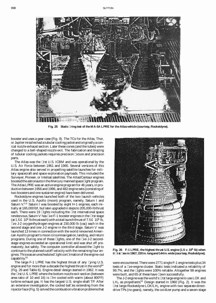
998 SUTTON
Fig. 25 Static � ring test of the MA-5A LPRE for the Atlas vehicle (courtesy, Rocketdyne).
booster and uses a gear case (Fig. 9). The TCs for the Atlas, Thor,or Jupiter missiles had a tubular cooling jacket and originallya con-ical nozzle exhaust section. Later these cones (and the tubes) werechanged to a bell-shaped nozzle exit. The fabrication and brazingof tubular cooling jackets requires precision � xture and precisionparts.
The Atlas was the � rst U.S. ICBM and was operational by theU.S. Air Force between 1961 and 1965. Several versions of thisAtlas engine also served in propelling satellite launches for mili-tary spacecraft and space exploration payloads. This included theSurveyer, Pioneer, or Intelsat satellites. The Atlas/Centaur enginesboosted the astronauts in the Mercury manned space� ight program.The Atlas LPRE was an active engine program for 46 years, in pro-duction between 1956 and 1996, and 482 engine sets (consistingoftwo boosters and one sustainer engine) have been delivered.
Rocketdyne engines launched both of the two launch vehiclesused in the U.S. Apollo (moon) program, namely, Saturn I andSaturn V.5;6 Saturn I was boosted by eight H-1 engines, each ini-tially at 165,000 lbf, but later upgraded in steps to 205,000-lbthrusteach. There were 19 � ights including the � rst international spacerendezvous.Saturn V has � ve F-1 booster engines in the � rst stage(at 1:5 £ 106 lb thrusteach)with a total launch thrust of 7:5 £ 106 lb,� ve J-2 oxygen/hydrogen engines at 230,000 lb (vac) each in thesecond stage and one J-2 engine in the third stage. Saturn V waslaunched 13 times in connection with the world renowned Ameri-can Apollo program’s moon circumnavigation, landing, and returnprograms. During one of these � ights, one of the � ve J-2 second-stage engines exceeded an operational limit and was shut off pre-maturely, but safely. The computer controller allowed the � ight tocontinue to the planned cutoff velocity with the remaining four en-gines.This was an unscheduled� ight con� rmationof the engine-outcapability.53
The large F-1 LPRE has the highest thrust of any � ying U.S.engine and for more than a decade the highest thrust in the world54
(Fig. 26 and Table 6). Engine detail design started in 1962. It wasthe � rst U.S. LPRE where the bottom nozzle exit section (betweenarea ratio of 10 and 16) is � lm cooled with warm (about 800±F)turbine exhaust gas. It has the largest U.S. single-shaft TP. Afteran extensive investigation, the cooled baf� es extending from theinjector face (Fig. 5) solved the combustion vibration problems that
Fig. 26 F-1 LPRE, the highest thrust U.S. engine (1.5 ££ 106 lb) whenit � rst � ew in 1967; 220 in. long and 144 in. wide (courtesy, Rocketdyne).
were encountered.There were 2771 single F-1 engine tests plus 34tests of a � ve-engine cluster. Static tests indicated a reliability of99.7%, and the � ights were 100% reliable. Altogether 98 engineswere built, and 65 of these have � own successfully.
The J-2 engine was the world’s � rst large engine to use LOX andLH2 as propellants.54 Design started in 1960 (Fig. 2). It was the� rst large Rocketdyne LOX/LH2 engine with two separate direct-drive TPs (no gears), namely, the oxidizer pump and a seven-stage
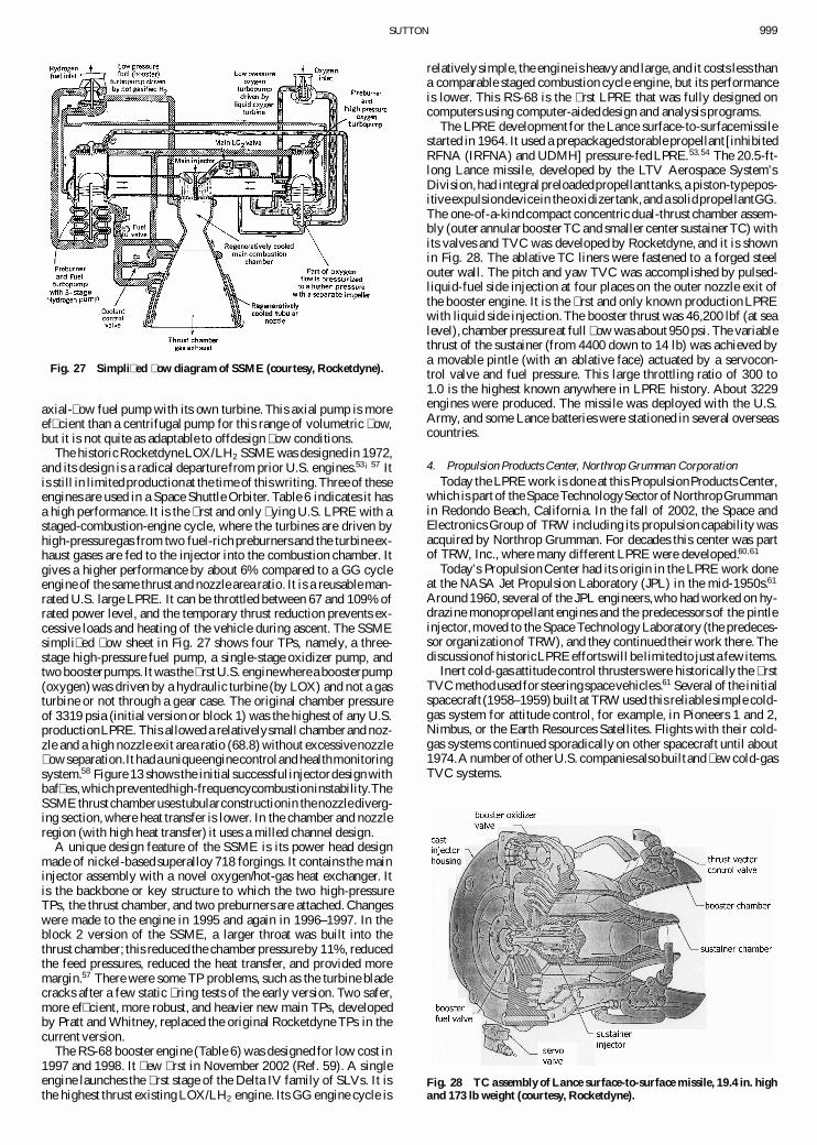
SUTTON 999
Fig. 27 Simpli� ed � ow diagram of SSME (courtesy, Rocketdyne).
axial-� ow fuel pump with its own turbine. This axial pump is moreef� cient than a centrifugal pump for this range of volumetric � ow,but it is not quite as adaptable to offdesign � ow conditions.
The historicRocketdyneLOX/LH2 SSME was designed in 1972,and its design is a radical departure from prior U.S. engines.53¡57 Itis still in limitedproductionat the time of this writing.Three of theseengines are used in a Space Shuttle Orbiter. Table 6 indicates it hasa high performance. It is the � rst and only � ying U.S. LPRE with astaged-combustion-engine cycle, where the turbines are driven byhigh-pressuregas from two fuel-rich preburners and the turbine ex-haust gases are fed to the injector into the combustion chamber. Itgives a higher performance by about 6% compared to a GG cycleengine of the same thrust and nozzle area ratio. It is a reusable man-rated U.S. large LPRE. It can be throttled between 67 and 109% ofrated power level, and the temporary thrust reduction prevents ex-cessive loads and heating of the vehicle during ascent. The SSMEsimpli� ed � ow sheet in Fig. 27 shows four TPs, namely, a three-stage high-pressure fuel pump, a single-stage oxidizer pump, andtwo boosterpumps. It was the � rstU.S. enginewherea boosterpump(oxygen) was driven by a hydraulic turbine (by LOX) and not a gasturbine or not through a gear case. The original chamber pressureof 3319 psia (initial version or block 1) was the highest of any U.S.productionLPRE. This allowed a relativelysmall chamberand noz-zle and a high nozzle exit area ratio (68.8) without excessive nozzle� owseparation.It hada uniqueenginecontroland healthmonitoringsystem.58 Figure 13 shows the initial successfulinjectordesign withbaf� es,whichpreventedhigh-frequencycombustioninstability.TheSSME thrust chamberuses tubularconstructionin thenozzlediverg-ing section, where heat transfer is lower. In the chamber and nozzleregion (with high heat transfer) it uses a milled channel design.
A unique design feature of the SSME is its power head designmade of nickel-based superalloy 718 forgings. It contains the maininjector assembly with a novel oxygen/hot-gas heat exchanger. Itis the backbone or key structure to which the two high-pressureTPs, the thrust chamber, and two preburners are attached. Changeswere made to the engine in 1995 and again in 1996–1997. In theblock 2 version of the SSME, a larger throat was built into thethrust chamber; this reduced the chamber pressureby 11%, reducedthe feed pressures, reduced the heat transfer, and provided moremargin.57 There were some TP problems, such as the turbine bladecracks after a few static � ring tests of the early version. Two safer,more ef� cient, more robust, and heavier new main TPs, developedby Pratt and Whitney, replaced the original Rocketdyne TPs in thecurrent version.
The RS-68 booster engine (Table 6) was designed for low cost in1997 and 1998. It � ew � rst in November 2002 (Ref. 59). A singleengine launches the � rst stage of the Delta IV family of SLVs. It isthe highest thrust existing LOX/LH2 engine. Its GG engine cycle is
relativelysimple, the engine is heavyand large, and it costs less thana comparable staged combustion cycle engine, but its performanceis lower. This RS-68 is the � rst LPRE that was fully designed oncomputers using computer-aideddesign and analysis programs.
The LPRE development for the Lance surface-to-surfacemissilestarted in 1964. It used a prepackagedstorable propellant [inhibitedRFNA (IRFNA) and UDMH] pressure-fedLPRE.53;54 The 20.5-ft-long Lance missile, developed by the LTV Aerospace System’sDivision,had integral preloadedpropellanttanks, a piston-typepos-itiveexpulsiondevicein theoxidizertank,and a solidpropellantGG.The one-of-a-kindcompact concentric dual-thrust chamber assem-bly (outer annular boosterTC and smaller center sustainerTC) withits valves and TVC was developed by Rocketdyne, and it is shownin Fig. 28. The ablative TC liners were fastened to a forged steelouter wall. The pitch and yaw TVC was accomplished by pulsed-liquid-fuel side injection at four places on the outer nozzle exit ofthe booster engine. It is the � rst and only known production LPREwith liquid side injection. The booster thrust was 46,200 lbf (at sealevel), chamber pressureat full � ow was about 950 psi. The variablethrust of the sustainer (from 4400 down to 14 lb) was achieved bya movable pintle (with an ablative face) actuated by a servocon-trol valve and fuel pressure. This large throttling ratio of 300 to1.0 is the highest known anywhere in LPRE history. About 3229engines were produced. The missile was deployed with the U.S.Army, and some Lance batteries were stationed in several overseascountries.
4. Propulsion Products Center, Northrop Grumman CorporationToday the LPRE work is done at this PropulsionProducts Center,
which is part of the Space TechnologySector ofNorthropGrummanin Redondo Beach, California. In the fall of 2002, the Space andElectronics Group of TRW including its propulsion capability wasacquired by Northrop Grumman. For decades this center was partof TRW, Inc., where many different LPRE were developed.60;61
Today’s Propulsion Center had its origin in the LPRE work doneat the NASA Jet Propulsion Laboratory (JPL) in the mid-1950s.61
Around 1960, several of the JPL engineers,who had worked on hy-drazine monopropellant engines and the predecessors of the pintleinjector,moved to the Space Technology Laboratory (the predeces-sor organizationof TRW), and they continued their work there. Thediscussionof historicLPRE effortswill be limited to just a fewitems.
Inert cold-gas attitude control thrusters were historically the � rstTVC methodused for steeringspacevehicles.61 Several of the initialspacecraft (1958–1959) built at TRW used this reliable simple cold-gas system for attitude control, for example, in Pioneers 1 and 2,Nimbus, or the Earth Resources Satellites. Flights with their cold-gas systems continued sporadically on other spacecraft until about1974.A numberof otherU.S. companiesalsobuiltand � ew cold-gasTVC systems.
Fig. 28 TC assembly of Lance surface-to-surface missile, 19.4 in. highand 173 lb weight (courtesy, Rocketdyne).
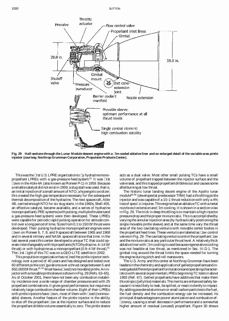
1000 SUTTON
Fig. 29 Half-sections through the Lunar Module descent engine with a � lm-cooled ablative liner and an enlarged detail of the variable area pintleinjector (courtesy, Northrop Grumman Corporation, Propulsion Products Center).
This was the � rst U.S. LPRE organizationto � y hydrazinemono-propellant LPREs with a gas-pressure-feed system.61 It was � rst� own in the Able 4A (also known as Pioneer P-1) in 1959. Becausea reliable catalyst did not exist in 1959, a slug start was used, that is,an initial injectionof a small amount of NTO, a hypergolicoxidizer;this created the high gas temperature necessary for the subsequentthermal decompositionof the hydrazine. The next spacecraft, Able4B, carried enough NTO for six slug starts. In the 1960s, Shell 405,an effective catalyst, became available, and a series of hydrazinemonopropellantLPRE systems (with pulsing,multiple thrustersanda gas-pressure-feed system) were then developed. These LPREswere capable for periodic rapid pulsing operation for attitude con-trol over a long period of time. Sizes from 0.1 to 150 lbf thrust weredeveloped. Their pulsing hydrazine monopropellant engines were� own on Pioneer 6, 7, 8, and 9 spacecraft between 1965 and 1968and in several military and NASA spacecraft since that time. In thelast several years this center developed a unique TC that could op-erate interchangeablywith bipropellants (NTO/hydrazine, 4–14 lbfthrust) or with hydrazine as a monopropellant (0.9–4 lbf thrust).61
The � rst � ight of this TC was on a GEO-LITE satellite in 2002.This propulsion organizationhas re� ned the pintle injector tech-
nology over a period of 40 years and has designed and tested over60 different pintle con� gurations over a thrust range between 5 and650,000lbf thrust.61;62 Mosthavea � xed (notmovable)pintle.An in-jectorwith a movablepintlesleeveis shownin Fig. 29 (Refs. 63–65).As of October 2001, there have not been any combustion instabil-ity incidence over a wide range of chamber pressures and with 25propellant combinations. It gives good performance, but requires arelatively large combustion chamber volume. Eight of their LPREswith pintle injectors have � own, most of them with � xed (nonmov-able) sleeves. Another feature of the pintle injector is the abilityto shut off the propellant � ow at the injector surface and to reducethe propellant dribble volume essentially to zero. The pintle sleeve
acts as a dual valve. Most other small pulsing TCs have a smallvolume of propellant trapped between the injector surface and thevalve seat, and this trapped propellantdribbles out and causes someafterburning at low thrust.
The historic lunar landing decent engine of the Apollo lunarmodule63;66 (developedat predecessorTRW) had a throttling pintleinjector and was capable of a 10–1 thrust reduction with only a 4%loss of speci� c impulse.This enginehad an ablativeTC with a metalnozzle exit extension and � lm cooling. It is shown in a section viewin Fig. 29. The trick in deep throttling is to maintain a high injectorpressuredrop and the proper mixture ratio. This is accomplishedbyvarying the annular injection area (by hydraulicallypositioning thesingle movable pintle sleeve) and at the same time vary the throatarea of the two cavitating venturis with movable center bodies inthe propellant feed lines. These venturis are labeled as � ow controlvalves in Fig. 29. The cavitatingventuris control the propellant � owand the mixture ratio at any particular thrust level.A relatively thickablative liner with � lm cooling is used becauseregenerativecoolingwas not feasible at low thrust, as mentioned in Sec. III.D.1. Thegimbal ring around the throat limits the space needed for turningthe engine during pitch and roll maneuvers.
The U.S. Army and this center at Northrop Grumman have beenleaders in the chemistryand applicationof gelledpropellantsand in-vestigateddifferentpropellantformulationsandoperatingcharacter-istics with several experimentalLPREs beginningTC tests in about1983 (Ref. 67). Gelled propellants have additives that make themthixotropic(jellylike)materials. The merits are enhanced safety be-cause it is less likely to leak, be spilled, or react violently to impact.By adding powdered aluminum or small carbon particlesto the fuel,the fuel density and the combustion energy can be increased. Itsprincipal disadvantagesare poorer atomization and combustion ef-� ciency, causing a small decrease in performance and a somewhathigher amount of residual (unused) propellant. Figure 30 shows
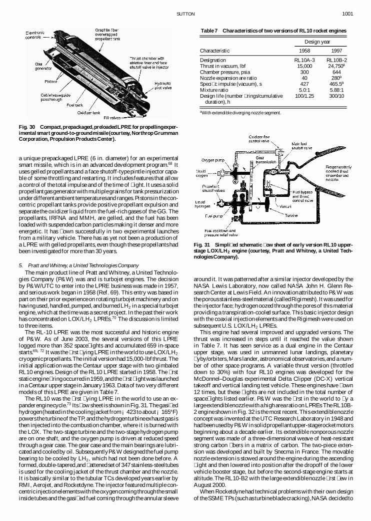
SUTTON 1001
Fig. 30 Compact,prepackaged,preloadedLPRE forpropellingexper-imental smart ground-to-groundmissile (courtesy, Northrop GrummanCorporation, Propulsion Products Center).
a unique prepackaged LPRE (6 in. diameter) for an experimentalsmart missile, which is in an advanced development program.68 Ituses gelled propellants and a face shutoff-typepintle injector capa-ble of some throttling and restarting. It includes features that allowa control of the total impulse and of the time of � ight. It uses a solidpropellantgas generatorwith multiplegrains for tank pressurizationunderdifferentambient temperaturesand ranges.Pistons in the con-centric propellant tanks provide positive propellant expulsion andseparate the oxidizer liquid from the fuel-rich gases of the GG. Thepropellants, IRFNA and MMH, are gelled, and the fuel has beenloaded with suspended carbon particles making it denser and moreenergetic. It has � own successfully in two experimental launchesfrom a military vehicle. There has as yet not been a production ofa LPRE with gelled propellants, even though these propellants hadbeen investigated for more than 30 years.
5. Pratt and Whitney, a United Technologies CompanyThe main product line of Pratt and Whitney, a United Technolo-
gies Company (P&W) was and is turbojet engines. The decisionby P&W/UTC to enter into the LPRE business was made in 1957,and serious work began in 1958 (Ref. 69). This entry was based inpart on their prior experienceon rotating turbojet machineryand onhaving used, handled,pumped, and burned LH2 in a special turbojetengine,which at the time was a secret project. In the past their workhas concentrated on LOX/LH2 LPREs.70 The discussion is limitedto three items.
The RL-10 LPRE was the most successful and historic engineof P&W. As of June 2003, the several versions of this LPRElogged more than 352 space� ights and accumulated 659 in-spacestarts.69¡72 It was the � rst � ying LPRE in the world to use LOX/LH2
cryogenicpropellants.The initial versionhad 15,000-lbfthrust.Theinitial application was the Centaur upper stage with two gimbaledRL10 engines. Design of the RL10 LPRE started in 1958. The � rststaticengine� ringoccurredin 1959,and the � rst � ightwas launchedin a Centaur upper stage in January1963. Data of two very differentmodels of this LPRE are given in Table 7.
The RL10 was the � rst � ying LPRE in the world to use an ex-panderenginecycle.73 Its � ow sheet is shown in Fig. 31.The gasi� edhydrogen(heated in the cooling jacket from¡423 to about¡165±F)powers the turbineof the TP, and the hydrogenturbineexhaustgas isthen injected into the combustion chamber, where it is burned withthe LOX. The two-stage turbine and the two-stage hydrogen pumpare on one shaft, and the oxygen pump is driven at reduced speedthrough a gear case. The gear case and the main bearings are lubri-cated and cooled by oil. SubsequentlyP&W designed the fuel pumpbearing to be cooled by LH2 , which had not been done before. Aformed, double-tapered,and � attenedset of 347 stainless-steeltubesis used for the cooling jacket of the thrust chamber and the nozzle.It is basically similar to the tubular TCs developed years earlier byRMI, Aerojet, and Rocketdyne.The injector featured multiple con-centric injectionelementswith the oxygencoming throughthe smallinside tubes and the gasi� ed fuel coming through the annular sleeve
Table 7 Characteristics of two versions of RL10 rocket engines
Design year
Characteristic 1958 1997
Designation RL10A-3 RL10B-2Thrust in vacuum, lbf 15,000 24,750a
Chamber pressure, psia 300 644Nozzle expansion are ratio 40 280a
Speci� c impulse (vacuum), s 427 465.5a
Mixture ratio 5.0:1 5.88:1Design life (number � rings/cumulative 100/1.25 300/10
duration), h
aWith extendible diverging nozzle segment.
Fig. 31 Simpli� ed schematic � ow sheet of early version RL10 upper-stage LOX/LH2 engine (courtesy, Pratt and Whitney, a United Tech-nologies Company).
around it. It was patterned after a similar injector developed by theNASA Lewis Laboratory, now called NASA John H. Glenn Re-search Center at Lewis Field. An innovationattributed to P&W wasthe porousstainless-steelmaterial (calledRigimesh). It was used forthe injector face; hydrogen oozed through the pores of this materialproviding a transpiration-cooled surface. This basic injector designwith the coaxial injection elements and the Rigimesh were used onsubsequent U.S. LOX/LH2 LPREs.
This engine had several improved and upgraded versions. Thethrust was increased in steps until it reached the value shownin Table 7. It has seen service as a dual engine in the Centaurupper stage, was used in unmanned lunar landings, planetary� yby/orbiters,Mars lander, astronomical observatories,and a num-ber of other space programs. A variable thrust version (throttleddown to 30%) with four RL10 engines was developed for theMcDonnel–Douglas experimental Delta Clipper (DC-X) verticaltakeoff and vertical landing test vehicle. These engines have � own12 times, but these � ights are not included in the total number ofspace� ights listed earlier. P&W was the � rst in the world to � y alargeextendiblenozzlewith a high area ratio on LPREs The RL10B-2 engine shown in Fig. 32 is the most recent. This extendiblenozzleconcept was invented at the UTC Research Laboratory in 1948 andhad beenusedbyP&W in solidpropellantupper-stagerocketmotorsbeginning about a decade earlier. Its extendible nonporous nozzlesegment was made of a three-dimensional weave of heat-resistantstrong carbon � bers in a matrix of carbon. The two-piece exten-sion was developed and built by Snecma in France. The movablenozzle extension is stowed around the engine during the ascending� ight and then lowered into position after the dropoff of the lowervehicle booster stage, but before the second-stage engine starts ataltitude. The RL10-B2 with the large extendiblenozzle � rst � ew inAugust 2000.
When Rocketdyne had technical problems with their own designof theSSME TPs (suchas turbinebladecracking),NASA decidedto
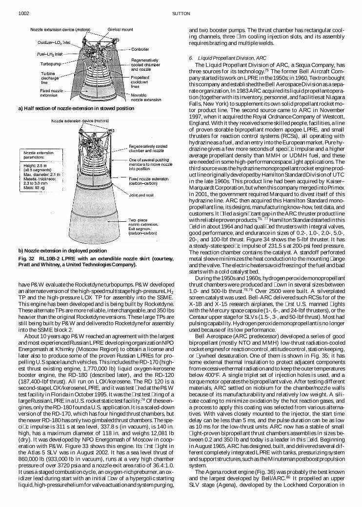
1002 SUTTON
a) Half section of nozzle extension in stowed position
b) Nozzle extension in deployed position
Fig. 32 RL10B-2 LPRE with an extendible nozzle skirt (courtesy,Pratt and Whitney, a United Technologies Company).
have P&W evaluate the Rocketdyne turbopumps. P&W developedan alternateversionof the high-speedmultistagehigh-pressureLH2
TP and the high-pressure LOX TP for assembly into the SSME.This engine has been developed and is being built by Rocketdyne.These alternate TPs are more reliable, interchangeable,and 350 lbsheavier than the original Rocketdyne versions. These large TPs arestill being built by P&W and delivered to Rocketdyne for assemblyinto the SSME block 2.
About 10 years ago P&W reached an agreement with the largestand most experiencedRussian LPRE developingorganizationNPOEnergomash at Khimky (Moscow Region) to obtain a license andlater also to produce some of the proven Russian LPREs for pro-pelling U.S space launch vehicles. This includes the RD-170 (high-est thrust existing engine, 1,770,000 lb) liquid oxygen-kerosenebooster engine, the RD-180 (described later), and the RD-120(187,400-lbf thrust). All run on LOX/kerosene. The RD 120 is asecond-stageLOX/keroseneLPRE, and it was test � red at the P&Wtest facility in Florida in October1995. It was the � rst test � ring of alargeRussianLPRE in a U.S. rocket static test facility.74 Of these en-gines, only the RD-180 founda U.S. application.It is a scaled-downversion of the RD-170, which has four hinged thrust chambers, butthe newer RD-180 has only two gimbaled thrust chambers.The spe-ci� c impulse is 311 s at sea level, 337.8 s (in vacuum), is 140 in.high, has a maximum diameter of 118 in. and weighs 12,081 lb(dry). It was developed by NPO Energomash of Moscow in coop-eration with P&W. Figure 33 shows this engine. Its � rst � ight inthe Atlas 5 SLV was in August 2002. It has a sea level thrust of860,000 lb (933,000 lb in vacuum), runs at a very high chamberpressure of over 3720 psia and a nozzle exit area ratio of 36.4:1.0.It uses a staged combustion cycle, an oxygen-richpreburner,an ox-idizer lead during start with an initial � ow of a hypergolic startingliquid,high-pressurehelium for valveactuationand system purging,
and two booster pumps. The thrust chamber has rectangular cool-ing channels, three � lm cooling injection slots, and its assemblyrequires brazing and multiple welds.
6. Liquid Propellant Division, ARCThe Liquid Propellant Division of ARC, a Sequa Company, has
three sources for its technology.75 The former Bell Aircraft Com-pany started its work on LPRE in the 1950s; in 1960,Textron boughtthis company and establishedthe Bell AerospaceDivision as a sepa-rate organization.In 1983 ARC acquired its liquidpropellantopera-tion (togetherwith its inventory, personnel,and facilities at NiagaraFalls, New York) to supplement its own solid propellant rocket mo-tor product line. The second source came to ARC in November1997, when it acquired the Royal Ordnance Company of Westcott,England. With it they received some skilled people, facilities, a lineof proven storable bipropellant modern apogee LPRE, and smallthrusters for reaction control systems (RCSs), all operating withhydrazineas a fuel, and an entry into the European market. Pure hy-drazine gives a few more seconds of speci� c impulse and a higheraverage propellant density than MMH or UDMH fuel, and theseare needed in some high-performancespace� ight applications.Thethird source was the hydrazinemonopropellantrocket engine prod-uct lineoriginallydevelopedby Hamilton StandardDivisionof UTCin the late 1960s. This product line had been acquired by Kaiser–MarquardtCorporation,but when this companymerged into Primexin 2001, the government required Marquard to divest itself of thishydrazine line. ARC then acquired this Hamilton Standard mono-propellant line, its designs,manufacturingknow-how, test data, andcustomers. It � lled a signi� cant gap in the ARC thruster product linewith reliableprovenproducts.75¡77 Hamilton Standardstarted in this� eld in about 1964 and had quali� ed thrusters with integral valves,good performance, and endurance in sizes of 0.2-, 1.0-, 2.0-, 5.0-,20-, and 100-lbf thrust. Figure 34 shows the 5-lbf thruster. It hasa steady-state speci� c impulse of 231.5 s at 200-psi feed pressure.The reaction chamber contains the catalyst. A standoff perforatedmetal sleeve minimizes the heat conduction to the mounting � angeand the valve.The electric heaters avoid freezingof the fuel and badstarts with a cold catalyst bed.
During the 1950s and 1960s, hydrogen peroxide monopropellantthrust chambers were produced and � own in several sizes between1.0- and 500-lb thrust.78;79 Over 2500 were built. A silverplatedscreen catalyst was used. Bell-ARC delivered such RCSs for of theX-1B and X-15 research airplanes, the � rst U.S. manned � ightswith the Mercury space capsule (1-, 6-, and 24-lbf thrusters), or theCentaur upper stage for SLVs (1.5-, 3-, and 50-lbf thrust).Most hadpulsing capability.Hydrogen peroxidemonopropellantis no longerused because of its low performance.
Bell Aerospace (ARC predecessor) developed a series of goodbipropellant (mostly NTO and MMH) low-thrust radiation-cooledrocket enginesfor reactioncontrol,attitudecontrol, stationkeeping,or � ywheel desaturation. One of them is shown in Fig. 35; it hassome external thermal insulation to protect adjacent componentsfrom excessive thermal radiationand to keep the outer temperaturesbelow 400±F. A single triplet set of injection holes is used, and atorque motor operates the bipropellantvalve. After testing differentmaterials, ARC settled on niobium for the chamber/nozzle wallsbecause of its manufacturability and relatively low weight. A sili-cate coating to minimize oxidation by the hot reaction gases, anda process to apply this coating was selected from various alterna-tives. With valves closely mounted to the injector, the start timedelay can be less than 5 ms, and the pulse duration can be as lowas 10 ms for the low-thrust units. ARC now has a stable of small� ight-proven bipropellant thrust chambers assemblies in sizes be-tween 0.2 and 350 lb and today is a leader in this � eld. Beginningin August 1965, ARC has designed, built, and deliveredseveral dif-ferent completely integrated LPRE with tanks, pressurizing systemand supportstructures,such as the Minutemanpostboostpropulsionsystem.
The Agena rocket engine (Fig. 36) was probably the best knownand the largest developed by Bell/ARC.80 It propelled an upperSLV stage (Agena), developed by the Lockheed Corporation in
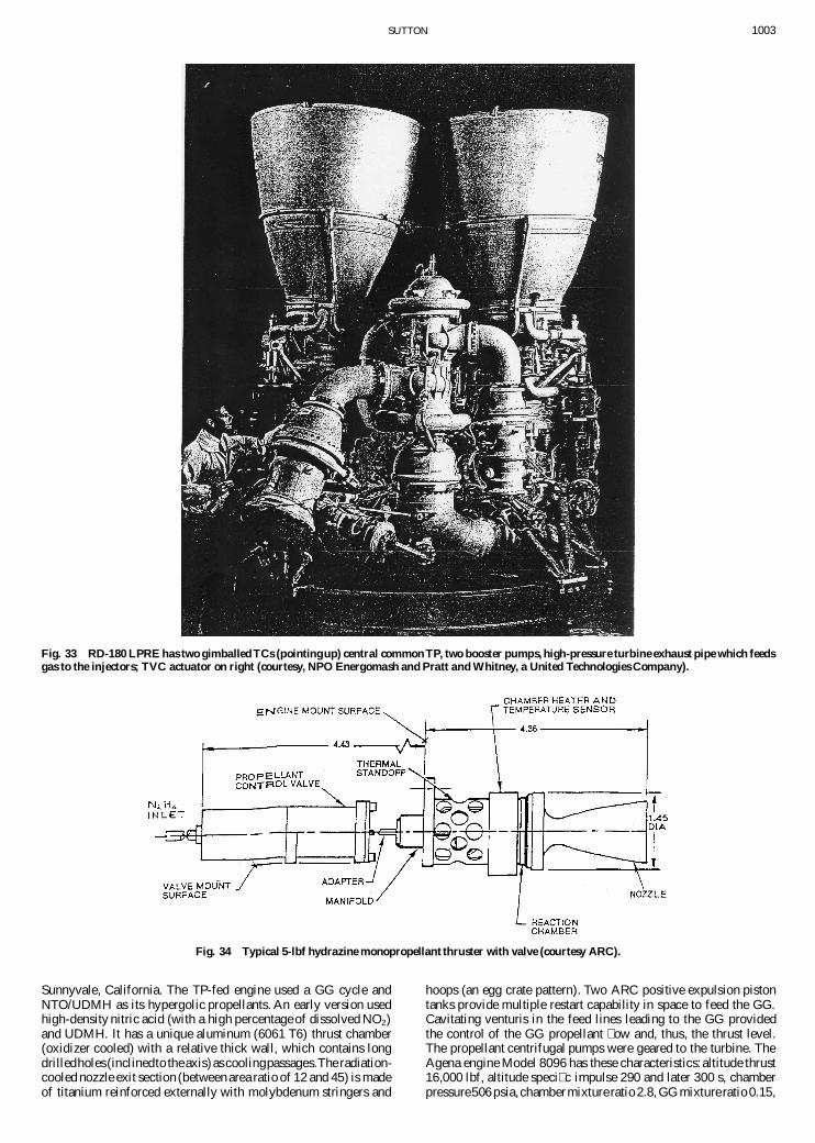
SUTTON 1003
Fig. 33 RD-180 LPRE has two gimballed TCs (pointing up) central common TP, two booster pumps, high-pressure turbine exhaust pipe which feedsgas to the injectors; TVC actuator on right (courtesy, NPO Energomash and Pratt and Whitney, a United Technologies Company).
Fig. 34 Typical 5-lbf hydrazine monopropellant thruster with valve (courtesy ARC).
Sunnyvale, California. The TP-fed engine used a GG cycle andNTO/UDMH as its hypergolic propellants. An early version usedhigh-density nitric acid (with a high percentage of dissolved NO2)and UDMH. It has a unique aluminum (6061 T6) thrust chamber(oxidizer cooled) with a relative thick wall, which contains longdrilledholes(inclinedto theaxis)as coolingpassages.The radiation-cooled nozzle exit section (between area ratio of 12 and 45) is madeof titanium reinforced externally with molybdenum stringers and
hoops (an egg crate pattern). Two ARC positive expulsion pistontanks provide multiple restart capability in space to feed the GG.Cavitating venturis in the feed lines leading to the GG providedthe control of the GG propellant � ow and, thus, the thrust level.The propellant centrifugal pumps were geared to the turbine. TheAgena engine Model 8096 has these characteristics:altitude thrust16,000 lbf, altitude speci� c impulse 290 and later 300 s, chamberpressure506 psia,chambermixture ratio 2.8, GG mixture ratio 0.15,

1004 SUTTON
dry weight 296 lb, nozzle area ratio 45, exit diameter 32.5 in., anda height of 83 in. A total of 418 Agena engines have been producedand 363 have � own with only one engine failure. This LPRE pro-pelled many different payloads, including the � rst U.S. satellite in acircular low orbit, the � rst into a polar orbit, and the � rst to performa signi� cant orbit velocity vector change. It also was the � rst largeupper-stageengine with a vacuum restart and the � rst to participatein a space rendezvousand docking operation with a manned space-craft, namely, the Gemini. A version of an Agena engine was alsoground tested with liquid � uorine and ammonia as propellants.
VI. General Findings, Comments, and ConclusionsThe LPRE � eld and its technology are today essentially mature.
The basic engine system and key components had been fairly wellde� ned about 40 or 50 years ago. High reliability numbers arerecorded by all LPREs in production. A large amount of data isavailable. For any particular kind of new LPRE, there are todaytwo or more organizations in the United States that can develop
Fig. 35 TC assembly 23-lbf thrust (of the Minuteman III postboostcontrol propulsion system) operates on NTO/MMH (courtesy, ARC).
Fig. 36 Agena 8096 engine (courtesy, ARC).
it with con� dence. Certainly there have been recent new technicalideas that have improved LPREs, such as better materials, lighterextendiblenozzles, or simpler TPs. There have also been a few newpotential requirements, such a microminiaturized LPREs, combin-ing LPREs with other means of propulsion, or reusable LPRE forreusable strapon boosters. There are still areas of this technologywhere R&D can lead to further improvement. However, the oppor-tunities for developing a truly new LPRE are today not as plentifulas they used to be.
The progress in the technology of LPREs has been truly remark-able in the last 82 years. Many of the technical milestones and keyLPREs have been discussed in this paper. The rate of innovation,introducingnew materialsor new designs,was higher in the � rst fewdecades of this history than it has been in the more recent decades.
The emphasis on the engine development criteria has changed.In the early decades the LPRE investigators were happy if the en-gine held together, ran for at least 10 s, and did not fail. Making itwork was the key objective. Soon the emphasis shifted to runningfor more than a minute. Then the aims became maximum possibleperformance, high reliability, safety, reduced costs, and for someapplications also long life. Making it environmentally compatiblehas become a goal more than a decade ago. Today the emphasisis still on these same criteria, but more attention is being given tocost.
The United States has the distinctionof being identi� ed with theAmerican Robert H. Goddard, a most important early pioneer inthis � eld, the � rst to build and run a LPRE and the � rst to launcha vehicle with a LPRE. His technical contributions are legendary.It is unfortunate that many of his inventions did not reach the U.S.industry in a timely manner.
Current space-relatedapplicationscan only be accomplishedwellby using LPREs. A number of the � ight applications, for whichLPRE were indeed appropriate, are obsolete today. In some ap-plications they have been replaced by other means of propulsion.For example, we no longer use LPREs for JATO, aircraft superper-formance, or sounding rocket vehicles. We are no longer buildingLPRE for ballistic missiles. The emphasis today is on applicationsfor space launch vehicles,spacecraftmaneuvers,or reaction controlfor the steering of � ying vehicles.
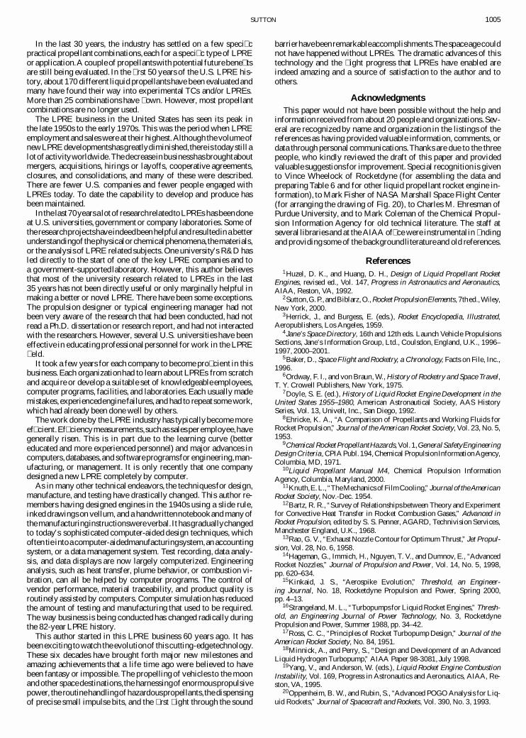
SUTTON 1005
In the last 30 years, the industry has settled on a few speci� cpracticalpropellant combinations,each for a speci� c type of LPREor application.A couple of propellantswith potentialfuturebene� tsare still being evaluated. In the � rst 50 years of the U.S. LPRE his-tory, about 170 different liquid propellantshave been evaluated andmany have found their way into experimental TCs and/or LPREs.More than 25 combinations have � own. However, most propellantcombinations are no longer used.
The LPRE business in the United States has seen its peak inthe late 1950s to the early 1970s. This was the period when LPREemployment and sales were at their highest.Although the volumeofnewLPRE developmentshasgreatlydiminished,there is todaystill alot of activityworldwide.The decreasein businesshasbroughtaboutmergers, acquisitions, hirings or layoffs, cooperative agreements,closures, and consolidations, and many of these were described.There are fewer U.S. companies and fewer people engaged withLPREs today. To date the capability to develop and produce hasbeen maintained.
In the last70yearsa lot of researchrelatedto LPREs hasbeendoneat U.S. universities, government or company laboratories. Some ofthe researchprojectshave indeedbeenhelpfuland resultedin a betterunderstandingof thephysicalor chemicalphenomena,thematerials,or the analysisof LPRE related subjects.One university’s R&D hasled directly to the start of one of the key LPRE companies and toa government-supportedlaboratory. However, this author believesthat most of the university research related to LPREs in the last35 years has not been directly useful or only marginally helpful inmaking a better or novel LPRE. There have been some exceptions.The propulsion designer or typical engineering manager had notbeen very aware of the research that had been conducted, had notread a Ph.D. dissertation or research report, and had not interactedwith the researchers. However, several U.S. universities have beeneffective in educatingprofessionalpersonnel for work in the LPRE� eld.
It took a few years for each company to become pro� cient in thisbusiness. Each organizationhad to learn about LPREs from scratchand acquire or develop a suitable set of knowledgeable employees,computer programs, facilities, and laboratories.Each usually mademistakes,experiencedengine failures, and had to repeat some work,which had already been done well by others.
The work done by the LPRE industry has typicallybecome moreef� cient.Ef� ciencymeasurements,suchas sales per employee,havegenerally risen. This is in part due to the learning curve (bettereducated and more experienced personnel) and major advances incomputers,databases,and softwareprogramsfor engineering,man-ufacturing, or management. It is only recently that one companydesigned a new LPRE completely by computer.
As in many other technical endeavors, the techniques for design,manufacture, and testing have drastically changed. This author re-members having designed engines in the 1940s using a slide rule,inked drawings on vellum, and a handwrittennotebookand many ofthe manufacturinginstructionswereverbal.It hasgraduallychangedto today’s sophisticated computer-aided design techniques, whichoften tie intoa computer-aidedmanufacturingsystem,an accountingsystem, or a data management system. Test recording, data analy-sis, and data displays are now largely computerized. Engineeringanalysis, such as heat transfer, plume behavior, or combustion vi-bration, can all be helped by computer programs. The control ofvendor performance, material traceability, and product quality isroutinely assisted by computers. Computer simulation has reducedthe amount of testing and manufacturing that used to be required.The way business is being conducted has changed radically duringthe 82-year LPRE history.
This author started in this LPRE business 60 years ago. It hasbeen exciting to watch the evolutionof this cutting-edgetechnology.These six decades have brought forth major new milestones andamazing achievements that a life time ago were believed to havebeen fantasy or impossible. The propelling of vehicles to the moonand other spacedestinations,the harnessingof enormouspropulsivepower, the routinehandlingof hazardouspropellants,the dispensingof precise small impulse bits, and the � rst � ight through the sound
barrierhavebeenremarkableaccomplishments.The spaceagecouldnot have happened without LPREs. The dramatic advances of thistechnology and the � ight progress that LPREs have enabled areindeed amazing and a source of satisfaction to the author and toothers.
AcknowledgmentsThis paper would not have been possible without the help and
information received from about 20 people and organizations.Sev-eral are recognized by name and organization in the listings of thereferences as having provided valuable information, comments, ordata through personal communications.Thanks are due to the threepeople, who kindly reviewed the draft of this paper and providedvaluable suggestions for improvement. Special recognition is givento Vince Wheelock of Rocketdyne (for assembling the data andpreparing Table 6 and for other liquid propellant rocket engine in-formation), to Mark Fisher of NASA Marshall Space Flight Center(for arranging the drawing of Fig. 20), to Charles M. Ehresman ofPurdue University, and to Mark Coleman of the Chemical Propul-sion Information Agency for old technical literature. The staff atseveral libraries and at the AIAA of� ce were instrumentalin � ndingand providingsome of the backgroundliteratureand old references.
References1Huzel, D. K., and Huang, D. H., Design of Liquid Propellant Rocket
Engines, revised ed., Vol. 147, Progress in Astronautics and Aeronautics,AIAA, Reston, VA, 1992.
2Sutton,G. P., andBiblarz,O., Rocket PropulsionElements, 7thed.,Wiley,New York, 2000.
3Herrick, J., and Burgess, E. (eds.), Rocket Encyclopedia, Illustrated,Aeropublishers, Los Angeles, 1959.
4Jane’s Space Directory, 16th and 12th eds. Launch Vehicle PropulsionsSections, Jane’s Information Group, Ltd., Coulsdon, England, U.K., 1996–1997, 2000–2001.
5Baker, D., Space Flight and Rocketry, a Chronology, Facts on File, Inc.,1996.
6Ordway, F. I., and von Braun, W., History of Rocketry and Space Travel,T. Y. Crowell Publishers, New York, 1975.
7Doyle, S. E. (ed.), History of Liquid Rocket Engine Development in theUnited States 1955–1980, American Astronautical Society, AAS HistorySeries, Vol. 13, Univelt, Inc., San Diego, 1992.
8Ehricke, K. A., “A Comparison of Propellants and Working Fluids forRocket Propulsion,” Journal of the American Rocket Society, Vol. 23, No. 5,1953.
9ChemicalRocket PropellantHazards, Vol. 1,GeneralSafetyEngineeringDesign Criteria, CPIA Publ. 194,Chemical PropulsionInformationAgency,Columbia, MD, 1971.
10Liquid Propellant Manual M4, Chemical Propulsion InformationAgency, Columbia, Maryland, 2000.
11Knuth,E.L., “TheMechanics ofFilmCooling,” Journalof theAmericanRocket Society, Nov.-Dec. 1954.
12Bartz, R. R., “Survey of Relationshipsbetween Theory and Experimentfor Convective Heat Transfer in Rocket Combustion Gases,” Advanced inRocket Propulsion, edited by S. S. Penner, AGARD, Technivision Services,Manchester England, U.K., 1968.
13Rao, G. V., “Exhaust Nozzle Contour for Optimum Thrust,” Jet Propul-sion, Vol. 28, No. 6, 1958.
14Hageman, G., Immich, H., Nguyen, T. V., and Dumnov, E., “AdvancedRocket Nozzles,” Journal of Propulsion and Power, Vol. 14, No. 5, 1998,pp. 620–634.
15Kinkaid, J. S., “Aerospike Evolution,” Threshold, an Engineer-ing Journal, No. 18, Rocketdyne Propulsion and Power, Spring 2000,pp. 4–13.
16Strangeland, M. L., “Turbopumps for Liquid Rocket Engines,” Thresh-old, an Engineering Journal of Power Technology, No. 3, RocketdynePropulsion and Power, Summer 1988, pp. 34–42.
17Ross, C. C., “Principles of Rocket Turbopump Design,” Journal of theAmerican Rocket Society, No. 84, 1951.
18Minnick, A., and Perry, S., “Design and Development of an AdvancedLiquid Hydrogen Turbopump,” AIAA Paper 98-3081, July 1998.
19Yang, V., and Anderson, W. (eds.), Liquid Rocket Engine CombustionInstability, Vol. 169, Progress in Astronautics and Aeronautics, AIAA, Re-ston, VA, 1995.
20Oppenheim, B. W., and Rubin, S., “Advanced POGO Analysis for Liq-uid Rockets,” Journal of Spacecraft and Rockets, Vol. 390, No. 3, 1993.
1006 SUTTON
21Reardon, F. H., “Combustion Stability Speci� cations and Veri� cationProcedure,” Publ. 247, Chemical Propulsion Information Agency, Laurel,MD, Oct. 1973.
22Lehman, M., This High Man, The Life of Robert H. Goddard, Farrar,Strauss and Co., New York, 1963.
23Goddard,E. C., and Pendray,G. E. (eds.), The Papers of Robert H. God-dard, Vol. 1, 1898–1924; Vol. 2, 1925–1937, Vol. 3, 1938–1945; McGraw–Hill, New York, 1970, p. 1707.
24Goddard, E. C., and Pendray, G. E., Robert H. Goddard, Rocket De-velopment, Liquid Fuel Rocket Research, 1929–1941, Prentiss–Hall, En-glewood Cliffs, NJ, 1948 (reissued 1961); also Goddard, R. H., “LiquidPropellant Rocket Development,” Smithsonian Miscellaneous Collections,Vol. 95, No. 3, 1936.
25Goddard, R. H., “A Method for Reaching Extreme Altitudes,” Smithso-nian Miscellaneous Collections, Vol. 71, No. 2, 1919.
26Winter, F. H., Prelude to the Space Age, The Rocket Societies: 1924 to1940, National Air and Space Museum, Smithsonian Inst., Washington,DC,1983.
27“The Flight of Experimental Rocket No. 2” Astronautics, No. 26, 1933,pp. 1–11.
28Pendray, G. E., “Early Rocket Developments of the American RocketSociety,” First Steps Toward Space, Vol. 6, American Astronautical Society,Univelt, San Diego, CA, Chap. 14; also Truax, R. C., “Annapolis RocketMotor Development,” First Steps Toward Space, Vol. 6, American Astro-nautical Society, Univelt, San Diego, CA, Chap. 27; also Durant, F. C., III,and James, G. S. (eds.), First Steps toward Space, American AstronauticalSociety History Series, Vol. 6, 1985.
29Truax, R. C., “Liquid Propellant Rocket Development by the U.S. Navyduring World War II: A Memoir,” American Astronautical Society HistorySeries, Vol. 12, Univelt, San Diego, CA, 1991, pp. 326–332.
30Malina, F. J., “The U.S. Army Air Corps Jet Propulsion ResearchProject, GALCIT Project No. 1, 1939–1946: A Memoir,” 3rd History Sym-posium of the International Academy of Astronautics, 1969.
31von Karman, T., and Edson, L., The Wind and Beyond, Theodore vonKarman, Little Brown, Boston, 1967.
32Summer� eld, M., Powell, W., and Crofut, E., “Development of a LiquidJet Unit and its Operation on an A-20 Aiplane,” Jet Propulsion Lab., JPLRept. 1–13, California Inst. of Technology, Pasadena, CA, Sept. 1942,
33Shesta, J., “Reaction Motors, Inc., the � rst Large Scale AmericanRocket Company: A Memoir,” 12th History Symposiumof the InternationalAcademy of Astronautics, Oct. 1978; also American Astronautical SocietyHistory Series, Vol. 19, Univelt, San Diego, CA, 1995, Chap. 7.
34Ordway, F. I., III, and Winter,F. H., “Reaction Motors, Inc.:A CorporateHistory, 1941–1958, Part I, Institutional Development,” American Astonau-tical Society History Series, Univelt, San Diego, CA, 1994, Chap. 7; alsoWinter, F. H., and Ordway, F. I., “Part II, Research and Development Ef-forts,” American Astronautical Society History Series, Univelt, San Diego,CA, 1994,Chap. 8; also Ordway, F. I., “Reaction Motors Divisionof ThiokolCorporation, an Operational History, 1958–1972 (Part II),” American As-tronautical Society History Series, Vol. 12, Univelt, San Diego, CA, 1991,Chap. 11; also Winter, F. H., “Reaction Motors Division of Thiokol Cor-poration, A Project History, 1958–1972 (Part III),” American AstronauticalSociety History Series, Vol. 12, Univelt, San Diego, CA, 1991, Chap. 12.
35Winter,F.H., “Black Betsy,” The 6000C-4Rocket Engine,1945–1989—Part 2,” American Astronautical Society History Series, Vol. 17, Univelt, SanDiego, CA, 1991, Chap. 11.
36Winter, F. H., and James, G. S., “Highlights of 50 Years of Aerojet,A Pioneering American Rocket Company,” History of Rocketry and Astro-nautics, edited by P. Jung, American Astronautical Society History Series,Vol. 22, Univelt, San Diego, CA, 1998, Chap. 4.
37Umholtz, P., “Liquid Rocketry,” Aerojet, The Creative Company, Aero-jet History Group, Sacramento, CA, 1995, Chap. 3.
38Personal communications,Fisher,C. B., 2001;also Nguyen,T.V., 2002;also Calhoun, D., and Mueggenburg, H. H., 1990s.
39Schnare, C. W., “Development of ATO and Engines for Manned Air-craft,” American Rocket Society Paper 2088-61, 1961.
40Ehresman, C. M., “Liquid Rocket Propulsion Applied to Manned Air-craft in Historical Perspective,” AIAA Paper 91-2554, June 1991.
41Stiff, R., “Storable Liquid Rockets,” AIAA Paper 67-977, Oct. 1961.42Aerojet’s Data sheets (several) and Aerojet Manuals, EnginesofTitan II
(1983), Titan III SLV (1992), and the Titan IV (2000).43Meland, L. C., and Thompson,F. C.,“History of the Titan LiquidRocket
Engines,” AIAA Paper 89-2389, June 1989; also Adams, L. J.,“The Evo-lution of the Titan Rocket—Titan I to Titan II,” American AstronauticalSociety History Series, Vol. 19, Univelt, San Diego, CA, 1997.
44Limerick, C., et al., “On Overview of the K-1 Reusable PropulsionSystem,” AIAA Paper 97-3120, July 1997.
45Personal communications, Stechman, R. C., Galbreath, J. J., andMorgan, O., Aerojet Redmond Center, formerly General Dynamics, 2001,2002, 2003.
46Productbrochuresand data sheets, MarquardtCo., Van Nuys,CA, 1990,Primex Aerospace Co. Redmond, WA, 1997, and General Dynamics Corp.Redmond, WA, 2001.
47Morgan, O. M., and Meinhardt, D. S., “Monopropellant SelectionCriteria—Hydrazine and other Options,” AIAA Paper 95-2595, June 1995.
48Schmidt, E. W., Hydrazineand its Derivatives, Preparation,Properties,Applications, Wiley, New York, 1984 (2nd rev. ed. 2002).
49Stechman, R. C., and Sumpter, D., “Development History of the ApolloReaction Control System Rocket Engine,” AIAA Paper 89-2388, July 1989.
50Murphy, J. M., “Liquid Rocket Propulsion System Advancements,1946–1970,” 14th History Symposium of the International Academy of As-tronautics, Sept. 1980.
51Iacobellis, S., “Liquid Rocket Engines, Their Status and Their Future,”AIAA Paper 66-828, 1966.
52Vilja, J., “Rocketdyne Advanced Propulsion System Overview,” AIAAPaper 97-3309, 1997.
53Personal communications, Wheelock, V., Schuster, E., Minami, H.,Halchak, J., and others, Rocketdyne, 1997–2003.
54Data sheets or data folder on Lunar Module Ascent Engine, RedstoneEngine, F-1, J-2, H-1, Atlas, Thor/Delta, Lance, and others, The Boeing Co.,Rocketdyne, Propulsion and Power, Conogu Park, CA, 1987–2003.
55Smith, R. A., and Minami, H. M., “History of the Atlas Engine,” editedby S. E. Doyle, American Astronautical Society History Series, Vol. 13,Univelt, San Diego, CA, 1992, Chap. 3.
56Biggs, R. E., “Space Shuttle Main Engine—the First Ten Years,” editedby S. E. Doyle, American Astronautical Society History Series, Vol. 13,Univelt, San Diego, CA, 1992, Chap. 4.
57Colbo, H. I., “Development of the Space Shuttle Main Engine,” AIAAPaper 79-1141, July 1979; also Harris, S. L., “Block II: The New SpaceShuttle Main Engine,” AIAA Paper 96-2853, 1996.
58Mattox, R. M., and White, J. B., “Space Shuttle Main Engine Con-troller,” NASA TP 1932, 1981, p. 19; also Seitz, P. F., “Space Shuttle MainEngine Control System,” Society of Automotive Engineers, SAE Paper 73-0927, 1973.
59“RS-68 First Flight Edition,” Threshold, an Engineering Journal,No. 20, the Boeing Co., Rocketdyne Propulsion and Power, Winter2003; also Conley, D., Lee, N. Y., Portanova, P. L., and Wood, B. K.,“Evolved Expendable Launch Vehicle System: RS-68 Main Engine De-velopment,” 53rd International Astronautical Congress, Paper IAC-2.S.01,Oct. 2002.
60Sackheim, R. L., “TRW’s Family of High Performance Spacecraft En-gines: Status and Impact,” 1996 JANNAF Propulsion and Joint Subcommit-tee Meetings, Albuquerque,NM, Chemical Propulsion Information Agency,Laurel, MD, Dec. 1996.
61Personal communications,Dressler, G. A., Sackheim, R. L., and Hodge,K. F., TRW, 1997, 2000, 2001, and 2002.
62Dressler, G. A., and Bauer, J. M., “TRW Pintle Engine Heritage andPerformance Characteristics,” AIAA Paper 2000-3871, July 2000.
63TRW Data Sheet on Lunar ModuleDescent Engine, 1979, and on otherLPREs, Redondo Beach, CA, 1999.
64Mayer, N. L., “Advanced X-Ray Astrophysics Facility—Imaging(AXAF-I) Propulsion System,” AIAA Paper 96-2869, July 1996.
65Chazen, M. L., “High Performance Bipropellant Rhenium Engine,”AIAA Paper 98-3356, 1998.
66Staudhammer, E. P., et al., “The Descent Engine for the Lunar Module,”AIAA Paper 67-521, 1967.
67Natan, B., and Rahami, S., “The Status of Gel Propellants in theYear 2000,” Combustion of Energetic Materials, edited by K. K. Kuo andL. deLuca, Begel House, Boca Raton, FL, 2001.
68Hodge, K. F., Crofoot, T. A., and Nelson, S., “Gelled Propellants forTactical Missile Application,” AIAA Paper 99-2976, June 1999.
69Mulready, D., Advanced Engine Development at Pratt & Whitney, theInside Story of Eight Special Projects, 1946 to 1971, Society of AutomotiveEngineers, Warrendale, PA, 2001.
70Heald, D., “LH2 Technology was Pioneered on Centaur 30 Years Ago,”American Astronautical Society History Series, Vol. 21, Univelt, San Diego,CA, 1997.
71Personal communications, Pignoli, C., Pratt and Whitney Aircraft,United Technologies Corp., 2001 and Mills, P., Pratt and Whitney, a UnitedTechnologies Co., 2003.
72Tucker, J. E., “The History of the RL10 Upper Stage Rocket En-gine,” edited by S. E. Doyle, American Astronautical Society History Series,Vol. 13, Univelt, San Diego, CA, 1992, Chap 5; also Santiago, R.,“Evolutionof the RL10 Liquid Rocket Engine for a New Upper Stage Application,”AIAA Paper 96-3013, 1996.
73Brown, J. R., “Expander Cycle Engines for Shuttle Cryogenic UpperStages,” AIAA Paper 83-1311, 1983.
SUTTON 1007
74Croteau, M. C., Garbowski, R. C., and Minick,A. B., “Live Fire Testingof the NPO Energomash RD-120 Rocket Engine at Pratt & Whitney,” AIAAPaper 96-2608,1996; also Data sheets on the RD-170, RD-180, and RD-120engines, Pratt and Whitney Aircraft, United Technologies Corp., West PalmBeach, FL, 1997.
75Personal communications, Marvin, M., and Boorady, F., ARC, 2001,2002, and 2003; also ARC brochures on several products, and companyhistorical information.
76Marcus, M., “Historical Evolution of the Hydrazine Thruster Design,”AIAA Paper 90-1838, July 1990; also Polythress, C. A., and Conkey, G. H.,III, “Development of a Long Life 125-lbf Hydrazine Thruster,” AIAA Paper80-1170, 1980; also Francis, A. E., “Quali� cation Test for the Multiple
Satellite Dispenser 0.2 lbf Rocket Engine Assembly,” Technical Rept. Oct.1973, revised May 1974.
77Saenz, A., Jr., “Life Performance Evaluation of 22 N (5 lbf) Hy-drazine Attitude Control Engines,” U.S. Air Force Rocket Propulsion Lab.,USAF/RPL Technical Rept. Nov. 1980.
78E. Gribbon, E., Driscoll, R., and Marvin, M., “Demonstration test of a15 lbf Hydrogen Peroxide (90%) Thruster,” AIAA Paper 2000-3249, 2000.
79Bloom, R., Davis, N. S., and Levine, S. D., “Hydrogen Peroxide as aPropellant,” Journal of the American Rocket Society, Vol. 80, March 1950.
80DeBrock, S. C., and Rudey, C. J., “Agena Primary and SecondaryPropulsion Systems,” Journal of Spacecraft and Rockets, Vol. 11, No. 11,1974, pp. 769–777.