Embed Size (px)
Citation preview

Radioisotope Batteries
Jake Blanchard
University of Wisconsin
April 2010

Introduction
Radioisotope batteries provide reliable batteries with high energy density
They are valuable when long life is needed and recharging or refueling is difficult
Many of the conversion technologies can function in harsh environments
They can be very useful as onboard MEMS power sources

Applications
Long-lived cell phone batteries
Self-powered sensors on automobiles
Self-powered sensors in humans
Sensors for tracking animals
Building/bridge sensors
MEMS
Micro-robots
Smart Dust Networks

Caveats
Cost
Safety/regulation
◦ Shielding is generally simple
◦ Concern is with breakage of packaging
◦ Security is also an issue

Radioisotopes
Alpha emitters – release energetic He
nuclei – typically at 4-6 MeV per particle
Beta emitters – emit electrons or
positrons (and neutrinos or
antineutrinos) – energy spectrum
Gamma emitters – emit electromagnetic
radiation – penetrating - undesirable

Isotope Selection
Type of radiation◦ Alpha
◦ Beta
Half-Life◦ Long - Long battery life (238-Pu – 0.6 W/g, 86 yr half life)
◦ Short - Higher power density (210-Po – 137 W/g, 3 month half-life)
Avoid gammas in the decay chain (safety)
Watch out for (alpha, n) reactions and Brehmstrahlung
Watch particle range, displacement damage, and cost

Radioisotopes and decay
Isotope Average energy
Half life
Specific activity
Specific Power
Power Density
(KeV) (year) (Ci/g) (W/g) (W/cc)
63-Ni 17 100 57 0.0067 0.056
3-H
5.7 12 9700 0.33 -
90-Sr/ 90-Y
200/930 29/2 d 140 0.98 2.5
210-Po
5300 0.38 4500 140 1300
238-Pu 5500 88 17 0.56 11
244-Cm 5810 18 81 2.8 38
M
NX
M
NX
M-1N
Y
e- ne
M-2N-4
Y
2
4Hea-decay b-decay

Beta Spectra (E in MeV)

What is a Nuclear Battery?
Goal: convert energy from radioactive
decay to electricity
Options:
◦ Direct charge collection
◦ Indirect (scintillation)
◦ Betavoltaic
◦ Thermoelectric
◦ Thermionic
◦ thermophotovoltaic

Comparison
Consider 1 mg for power source
Source Energy Content (mW-hr)
Chemical Battery (Li-ion) 0.3
Fuel Cell (methanol, 50%) 3
210-Po (5% - 4 years) 3000
3-H (5% - 4 years) 500


Direct conversion nuclear battery: collecting charges emitted from radioisotopes with a capacitor to achieve high voltage output(J. H. Coleman, 1953)
Direct conversion nuclear battery
High voltage
Radioisotope
Collector
C
QV
10-100 kV voltages can be
created in vacuum

Static Accumulation
Linder, Rappaport, Loferski
•Early 1950’s
•Source at K
•D is electrical insulator
•Chamber is evacuated
•0.25 Ci Sr-90
•365 kV
•About 1 nA
•0.2 mW

Adding a Dielectric
Keller et al
•Early 1950’s
•Source at S
•D is dielectric; C is collector
•Radiation penetrates dielectric
•No need for vacuum
•High voltage
•Prevents secondary electrons from
getting back to source
•50 mCi Sr-90
•polystyrene
•7 kV

Secondary Collector
Shorr
•Use beta source
•MgO used to maximize
secondary’s
•Collector is graphite
coated Al
•1e-5 mm Hg vacuum

Contact Potential
Ionize gas between two plates
Dissimilar plates will develop
potential due to differing work
functions
Low efficiency (low absorption
coefficient) and high ionization
energy (30 eV)
Operates at 1-2 V
Shorr

Pacemakers
3 Ci Pu-238
~3 ounces, ~3 inches
<mW power levels
100 mrem/y to patient
Since supplanted by Li batteries (~10 yr life)
Regulators nervous about tracking Pu
Thermoelectric (some betacell concepts)
http://www.naspe.org/library/electricity_and_the_heart/

Radioisotope Thermoelectric
Generators (RTGs)
Used in many NASA
missions
Use radoisotope (usually
ceramic Pu-238) to
provide heat
Electricity produced by
thermoelectric
No moving parts
41 have been flown by
US
• Fuel: 2.7 kg. 133 kCi
• Power: 276 W
• Power (11 years): 216 W
• Total Weight: 56 kg
• Lifetime: over 20 years
• Dimensions: D=42 cm,
L=114 cm


Heating Units
NASA’s RHU
33 Ci
Power is 1 W
1.4 oz.
1 cubic inch
2.7 g of Pu-238 (oxide form)
Rugged, reliable
http://nuclear.gov/space/rhu-fact.html

A Compact Thermoelectric
John H. Glenn Research Center, Cleveland, Ohio
Hi-Z Technology and JPL
40 mW electric power
240 cm3, 300 g total weight

Betavoltaic Microbattereis
• First type: planar Si pn-diode with electroplated 63Ni
PN-diode
DIP
packageLeads Glass
Electroplated 63Ni thin film
-3
-2.5
-2
-1.5
-1
-0.5
0
0 50 100 150
Cu
rren
t (n
A)
Voltage (mV)
• Second type: inverted pyramid array Si pn-diode
0.25mCi 1mCi
0.71nA 2.41nA
64mW 115mV
0.04nW 0.24nW
IpVoc
Pmax
- Nanopower( 0.04~0.24nW) obtained/ - No performance degradation after 1 year
63NiCl/HCI solution
PN
Glass
(8Ci/l)
- Area magnification: 1.85 / - 0.32nW (128mV/2.86nA) obtained
• Efficiency:0.03~0.1% ~10 times > micromachined RTG

Scaling of Power
Currently 1mCi of 63Ni is used◦ Source density of~0.0625 mCi/mm2 leads to
2~8 nW/cm2
10mCi~100mCi of 63Ni is expected to be used◦ Source density is ~1~2 mCi/mm2
◦ 100nW ~200 nW can be obtained
◦ Gives 100~200 nW/cm2
Energy conversion efficiency of 0.5~1% is expected to be achieved◦ Theoretical conversion efficiency: 3~5%

Using Radioisotope 147Pm
• Another way to raise power output : using high energy power source
- 147Pm, with Eavg= 62 keV and Emax= 220 keV and half-life of 2.6 year is also
a promising pure beta source for microbattery.
• Preliminary Results
NP
147Pm
SiO2
-1m of SiO2 is used as protection layer
- Device area : 2mm 3mm
- 5mCi of 147Pm is used
- test result : Is= 140nA, Voc=183mV, Pmax = 16.8nW
- Conversion efficiency: 0.62%
- long-term stability is under test
-1.E-07
-8.E-08
-4.E-08
-1.E-23
0.00 0.05 0.10 0.15 0.20
Cu
rren
t (A
)
Voltage (V)

Porous Silicon
Try to maximize area exposed to source

Thin, Flexible Semiconductors
For low energy beta emitters, source
layers must be thin (sub-micron)
Range of particles in semiconductor is
also a few microns at most
Hence, thin semiconductors are an
advantage
Multi-layer devices can offer good power
density with good efficiency
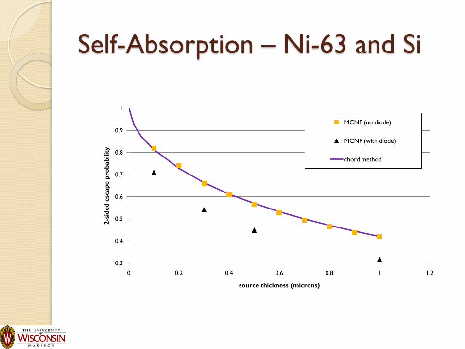
Self-Absorption – Ni-63 and Si
0.3
0.4
0.5
0.6
0.7
0.8
0.9
1
0 0.2 0.4 0.6 0.8 1 1.2
2-s
ided
esc
ap
e p
rob
ab
ilit
y
source thickness (microns)
MCNP (no diode)
MCNP (with diode)
chord method


Silicon Carbide
Wide Bandgap semiconductors offer
hope for larger efficiencies
Simulations indicate on the order of 25%
conversion efficiency

A “New” Concept

Self reciprocating cantilever
0 2 4 60
10
20
30
Time (minute)
Dis
tan
ce (m
)
Experimental dataCalculated values
Initial gap (d0): 33 m
Period: 6 min. 8 sec.
Residual charges: 2.310-11C
Peak force (kd0): 10.1 N
Assumed Collection efficiency (a): 10%

Self-reciprocating SiN cantilever
The cantilever is made of low stress SiN thin film with dimensions 500 m 300 m 1.7 m .
The cantilever is mounted on a DIP package for wire bonding.
Four poly resistors form a Wheatstone bridge to measure the deflection of the cantilever.
The signal from the Wheatstone bridge is sent to an instrumentation amplifier and then output from the amplifier is measured.
0 5 10 15 20 25 30 350
0.2
0.4
0.6
0.8
1
1.2
Time (s)
Dis
tan
ce (
m)
Blue: measured deflectionRed: signal from the Wheatstone bridge

Self-powered
Sensor/Actuator/Transmitter
-0.5 0 0.5 1 1.5 2 2.5
-0.2
-0.1
0
0.1
0.2
0.3
Time (s)
Vo
ltag
e (
V)
(a) (b)
C1
C2
C3
To oscilloscope Nickel-63 source
PZT
Au electrodes
C1
C2
C3 C4
ε
To oscilloscope
Nickel-63 source
PZT
dt
dVCI 1

Bottom Line
Market is applications which can justify
cost and risk of using radioisotope fuels
Advantage is very long life

Comparing Technologies