Embed Size (px)
Citation preview

HISTORY OF CONSTRUCTION CFR 257.73(c)(1)
Bottom Ash Pond
Big Sandy Plant Louisa, Kentucky
October, 2016
Prepared for: Kentucky Power – Big Sandy Plant
Louisa, Kentucky
Prepared by: American Electric Power Service Corporation
1 Riverside Plaza
Columbus, OH 43215
Document No. GERS-16-067
i
Table of CONTENTS 1.0 OBJECTIVE ......................................................................................................................................................................... 1
2.0 DESCRIPTION OF CCR THE IMPOUNDMENT ................................................................................................... 1
3.0 SUMMARY OF OWNERSHIP {257.73(c)(1)(i)} ............................................................................................... 1
4.0 LOCATION OF THE CCR UNIT {257.73 (c)(1)(ii)} ......................................................................................... 1
5.0 STATEMENT OF PURPOSE {257.73 (c)(1)(iii)} ............................................................................................. 1
6.0 NAME AND SIZE OF WATERSHED THE CCR UNIT IS LOCATED {257.73 (c)(1)(iv)} ................... 2
7.0 DESCRIPTION OF THE FOUNDATION AND ABUTMENT MATERIALS {257.73(c)(1)(v)} ........ 2
8.0 DESCRIPTION OF EACH CONSTRUCTED ZONE OR STAGE OF THE CCR UNIT {257.73
(c)(1)(vi)} .................................................................................................................................................................................. 2
9.0 ENGINEERING STRUCTURES AND APPURTENANCES {257.73 (c)(1)(vii)}..................................... 3
10.0 SUMMARY OF POOL SURFACE ELEVATIONS, AND MAXIMUM DEPTH OF CCR {257.73
(c)(1)(vii)}................................................................................................................................................................................. 3
11.0 FEATURES THAT COULD ADVERSELY AFFECT OPERATION DUE TO MALFUNCTION OR
MIS-OPERATION {(257.73 (c)(1)(vii))} .................................................................................................................... 4
12.0 DESCRIPTION OF THE TYPE, PURPOSE AND LOCATION OF EXISTING INSTRUMENTATION
{257.73 (c)(1)(viii)} ............................................................................................................................................................. 4
13.0 AREA – CAPACITY CURVES FOR THE CCR UNIT {257.73 (c)(1)(ix)} ............................................... 4
14.0 DESCRIPTION OF EACH SPILLWAY AND DIVERSION {257.73 (c)(1)(x)} ..................................... 4
15.0 SUMMARY CONSTRUCTION SPECIFICATIONS AND PROVISIONS FOR SURVEILLANCE,
MAINTENANCE AND REPAIR {257.73 (c)(1)(xi)} ................................................................................................ 5
16.0 RECORD OR KNOWLEDGE OF STRUCTURAL INSTABILITY {257.73 (c)(1)(xii)}...................... 5
Attachments
Attachment A – Location Map
Attachment B – Design Drawings
Attachment C – Instrumentation Location Map
Attachment D – Stage-Storage Curve
1
1.0 OBJECTIVE This report was prepared by AEP-Geotechnical Engineering Services (GES) section to fulfill requirements
of CFR 257.73(c)(1).
2.0 DESCRIPTION OF CCR THE IMPOUNDMENT The Big Sandy Power Plant is located north of the City of Louisa, Lawrence County, Kentucky.
It is owned and operated by Kentucky Power. The facility operates two surface impoundments for
storing CCR called the Fly Ash Pond and the Bottom Ash Pond. This report deals with the history of
construction for the Bottom Ash Pond.
The Bottom Ash Pond is comprised of diked embankments on the East, West, South sides with the north
side abutting the adjoining the hillside. The Bottom Ash Pond is split into north and south cells. The
Bottom Ash Pond discharges into the Clearwater Pond (north/south) which discharges into the Reclaim
pond where water is pumped to the Fly Ash Pond. The combination of the Bottom Ash Pond, the
Clearwater Pond and the Reclaim Pond are commonly refered to as the Bottom Ash Pond complex.
The Big Sandy Power Plant has ceased burning coal and been refueled for natural gas. As such the
Bottom Ash pond will continue to remain in service as a wastewater pond.
3.0 SUMMARY OF OWNERSHIP {257.73(C)(1)(I)} [The name and address of the person(s) owning or operating the CCR unit: the name associated
with the CCR unit: and the identification number of the CCR unit if one has been assigned by the
state.]
The Big Sandy Power Plant is located at 23000 Highway 23, Lousia, KY 41230 near the City of Louisa,
Lawrence County, Kentucky. The Bottom Ash Pond is owned and operated by Kentucky Power. .
4.0 LOCATION OF THE CCR UNIT {257.73 (C)(1)(II)} [The location of the CCR unit identified on the most recent U.S. Geological Survey (USGS) 7 ½
minute or 15 minute topographic quadrangle map, or a topographic map of equivalent scale if
a USGS map is not available.]
A location map is included in Attachment A.
5.0 STATEMENT OF PURPOSE {257.73 (C)(1)(III)} [A statement of the purpose for which the CCR unit is being used.]
The Bottom Ash Pond is a surface impoundment for storing CCR. The Bottom Ash Pond is used for
primary settling and storage of bottom ash. The Bottom Ash pond is divided into two cells (north and
south. Water from the Bottom Ash Pond discharge through the Clearwater pond and into the Reclaim
2
Pond where it was pumped back for reuse or pumped to the Fly Ash Pond for discharge through the
permitted outfall.
6.0 NAME AND SIZE OF WATERSHED THE CCR UNIT IS LOCATED
{257.73 (C)(1)(IV)} [The name and size in acres of the watershed within which the CCR unit is located.]
The Bottom Ash Pond is located within the Big Sandy Watershed (HUC: 05070204) which is 258,956.8
acres (404.62 square miles). The Bottom Ash Pond is an upground reservoir and occupies approximately
3.5 acres.
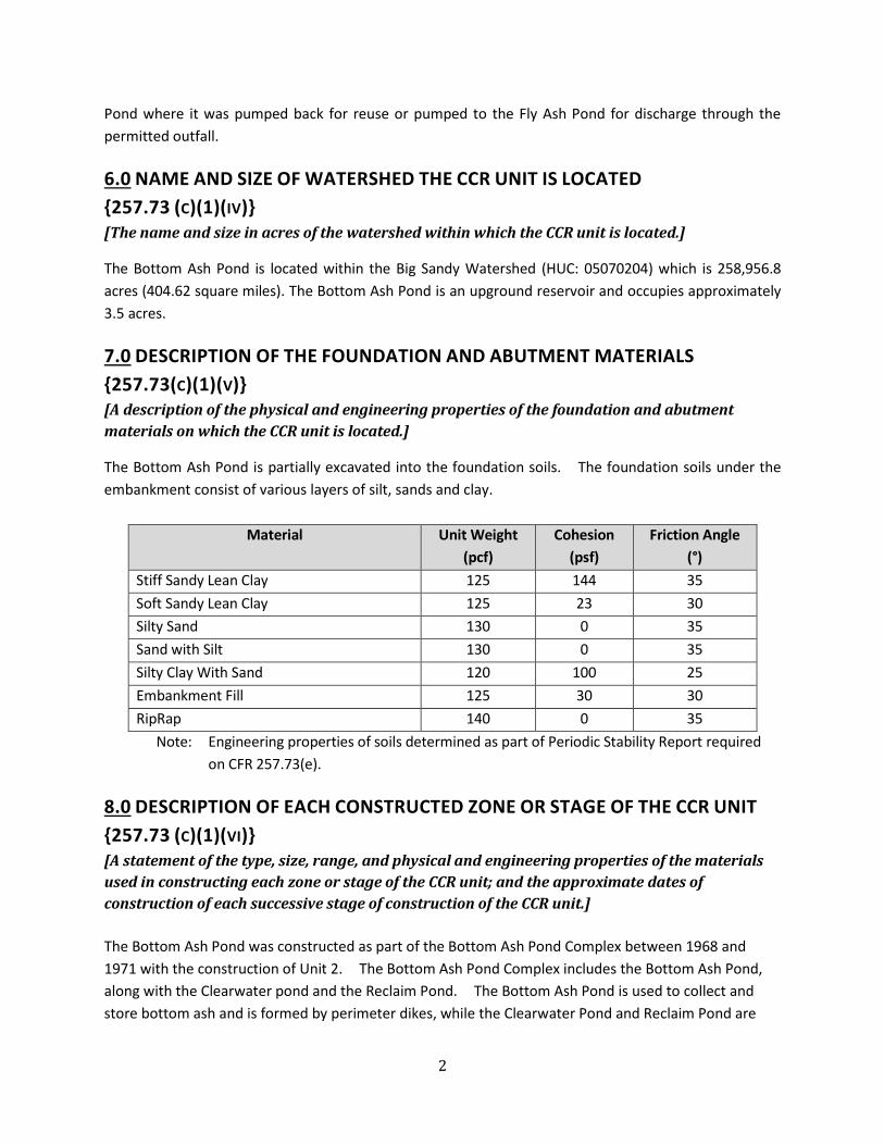
7.0 DESCRIPTION OF THE FOUNDATION AND ABUTMENT MATERIALS
{257.73(C)(1)(V)} [A description of the physical and engineering properties of the foundation and abutment
materials on which the CCR unit is located.]
The Bottom Ash Pond is partially excavated into the foundation soils. The foundation soils under the
embankment consist of various layers of silt, sands and clay.
Material Unit Weight
(pcf)
Cohesion
(psf)
Friction Angle
(°)
Stiff Sandy Lean Clay 125 144 35
Soft Sandy Lean Clay 125 23 30
Silty Sand 130 0 35
Sand with Silt 130 0 35
Silty Clay With Sand 120 100 25
Embankment Fill 125 30 30
RipRap 140 0 35
Note: Engineering properties of soils determined as part of Periodic Stability Report required
on CFR 257.73(e).
8.0 DESCRIPTION OF EACH CONSTRUCTED ZONE OR STAGE OF THE CCR UNIT
{257.73 (C)(1)(VI)} [A statement of the type, size, range, and physical and engineering properties of the materials
used in constructing each zone or stage of the CCR unit; and the approximate dates of
construction of each successive stage of construction of the CCR unit.]
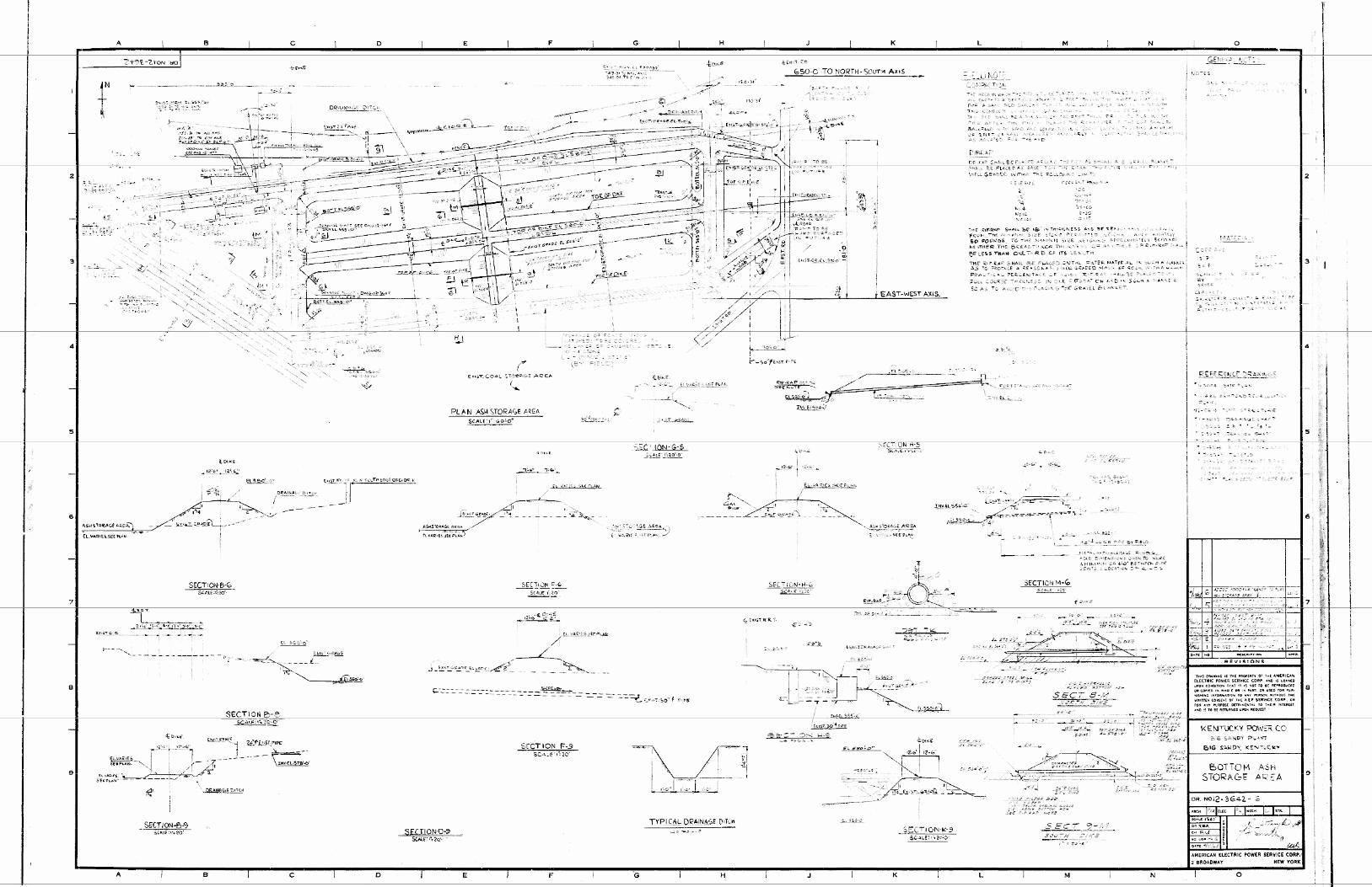
The Bottom Ash Pond was constructed as part of the Bottom Ash Pond Complex between 1968 and
1971 with the construction of Unit 2. The Bottom Ash Pond Complex includes the Bottom Ash Pond,
along with the Clearwater pond and the Reclaim Pond. The Bottom Ash Pond is used to collect and
store bottom ash and is formed by perimeter dikes, while the Clearwater Pond and Reclaim Pond are

3
incised and used for water storage and treatment. The Bottom Ash Pond is divided into two halves to
allow management of CCR material during plant operations. The Bottom Ash Pond dike consists
cohesive embankment fill with a grouted riprap shell on the interior slope and a grassed slope on the
exterior. Riprap is placed on the exterior of the common dike with the Clearwater pond. The grouted
riprap was installed as part of maintenance activities in 2010. The engineering properties of these two
layers are provided in the table in Section 7.0. A detailed engineering design report is not available;
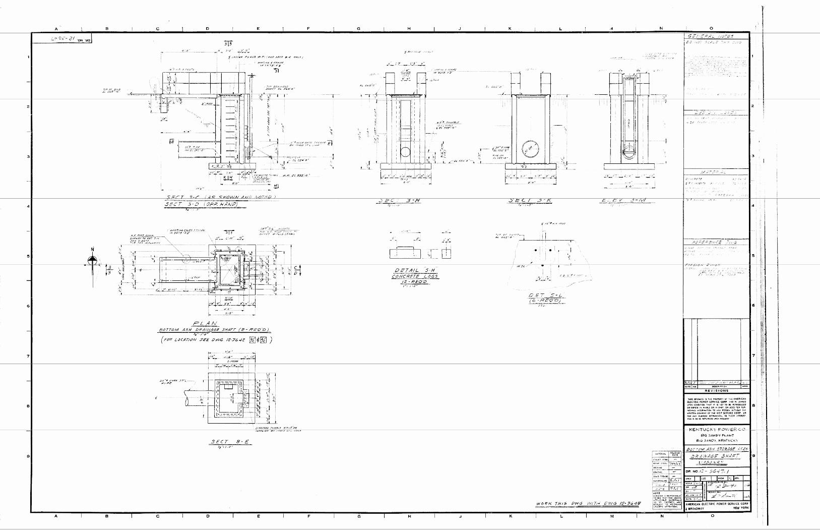
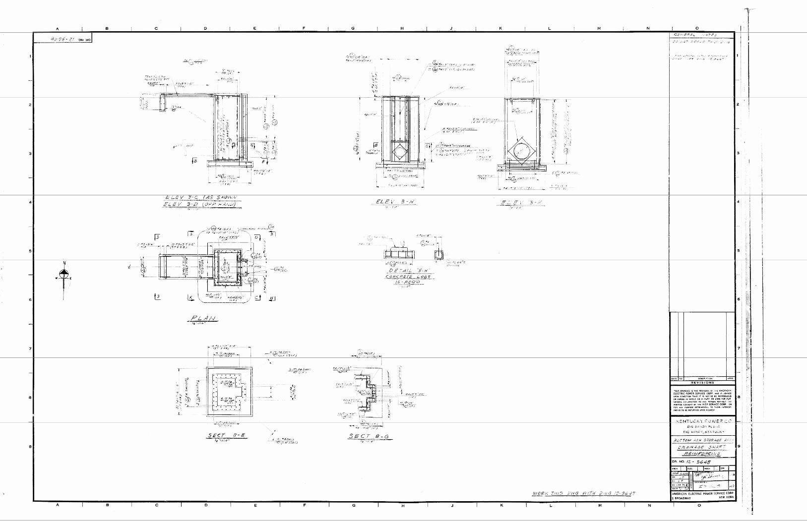
however, engineering construction drawings are included in Attachment B.
9.0 ENGINEERING STRUCTURES AND APPURTENANCES {257.73 (C)(1)(VII)} [At a scale that details engineering structures and appurtenances relevant to the design,
construction, operation, and maintenance of the CCR unit, detailed dimensional drawings of
the CCR unit, including a plan view and cross sections of the length and width of the CCR unit,
showing all zones, foundation improvements, drainage provisions, spillways, diversion ditches,
outlets, instrument locations, and slope protection…]
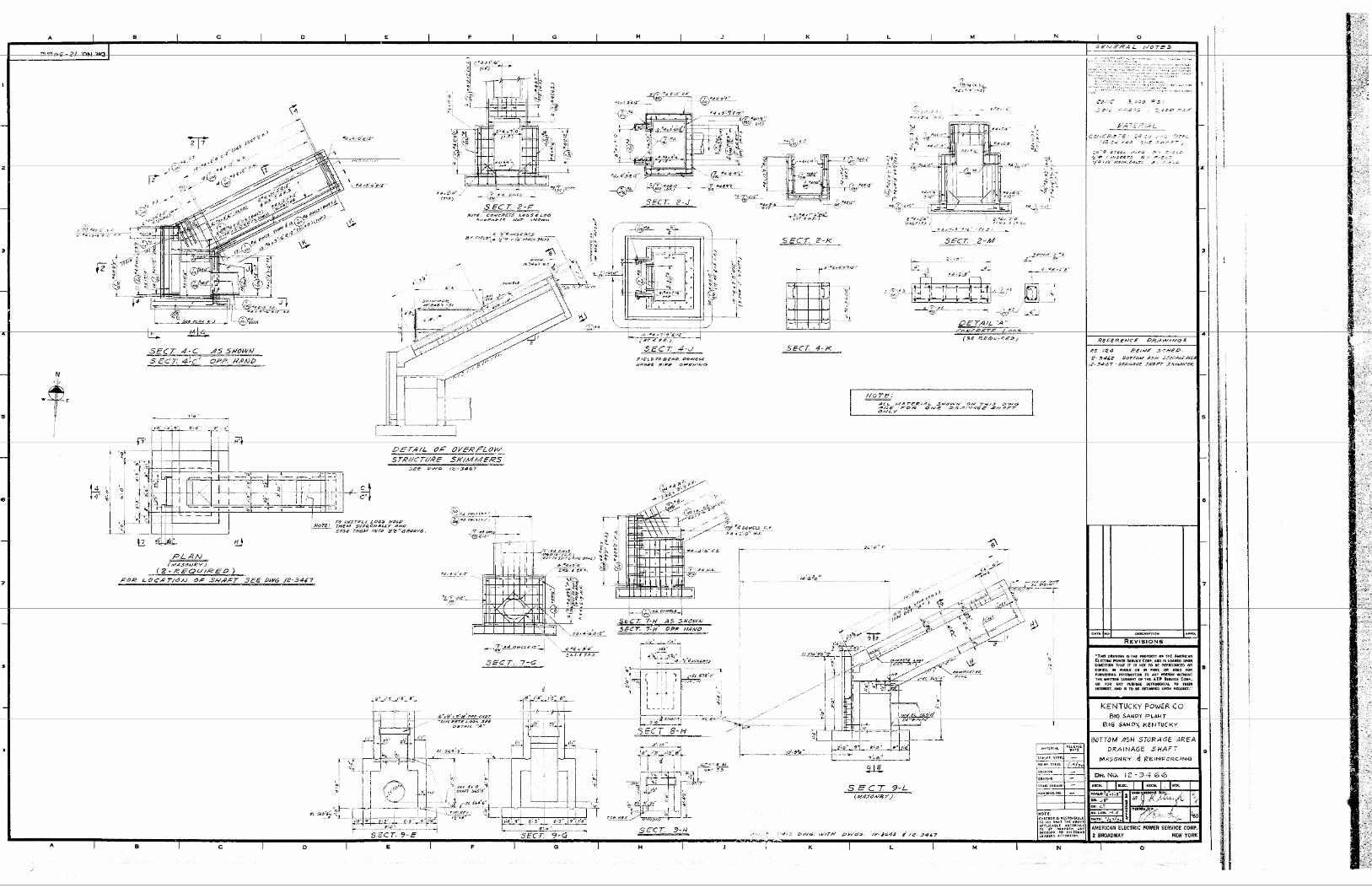
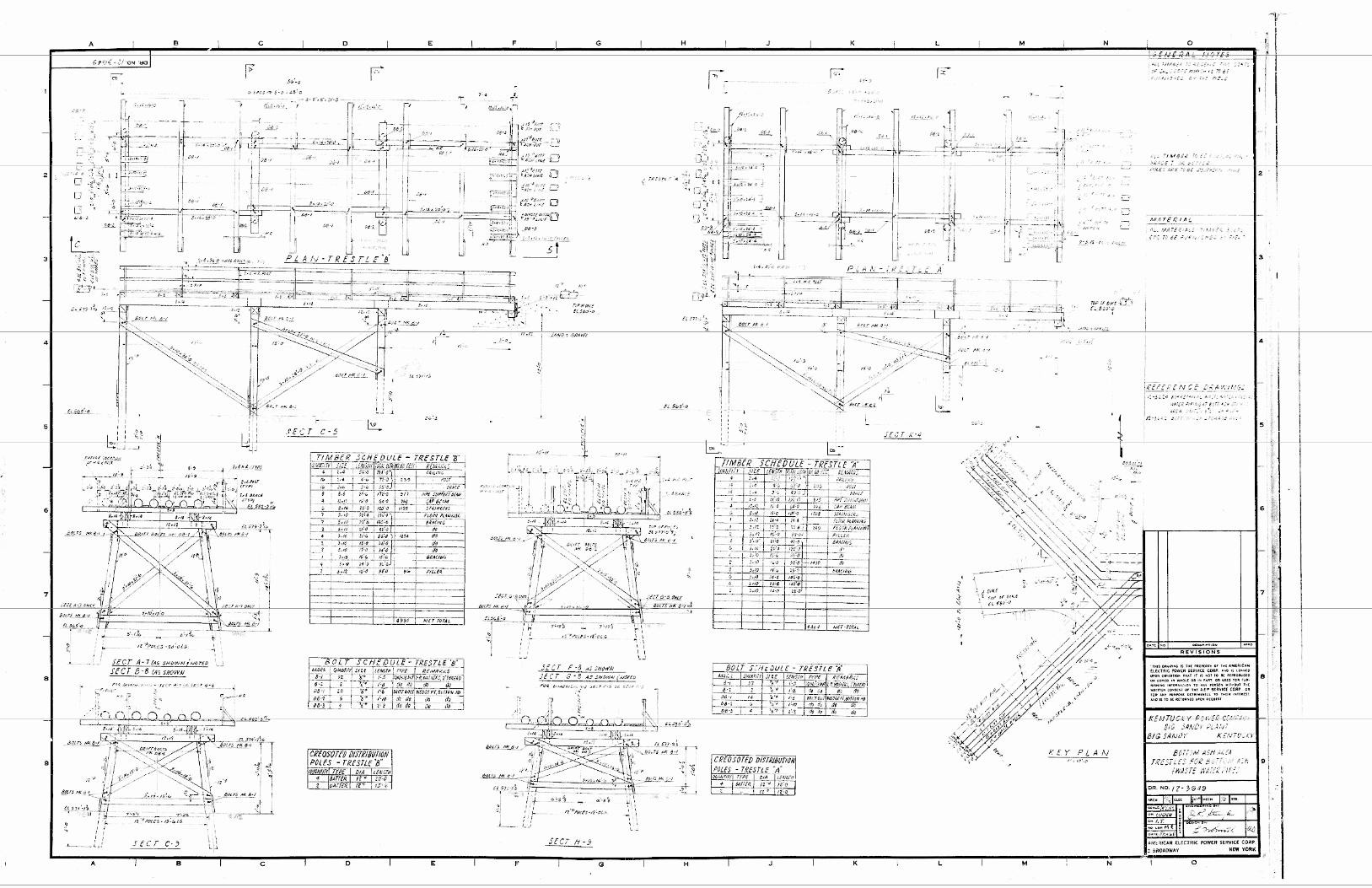
Water and waste material were discharged into the Bottom Ash Cells from a pipes located on wooden
tressle structure located in each cell. The engineering drawings for the wooden trestle structure are
included in Attachment B.
The outlet for each cell of the Bottom Ash Pond is a 24-in steel standpipe connected to a 24-in pipe that
discharges into the cell of the Clearwater Pond. A metal skimmer structure is located around the drop
outlet to control the discharge of solids from the bottom ash pond. An 12-in steel pipe with a slide
gate is connected to the 24-in discharge pipe to allow dewatering of the bottom ash cell. Additionally,
a 30-in corrugated HDPE plastic pipe is located next to the outfall structure and allows plant personnel
to place a pump to assist with dewatering stored bottom ash. CCR material is periodically excavated
from the Bottom Ash Pond and hauled to the Fly Ash Pond for disposal. The engineering drawings in
Attachment B show a concrete sloping riser as the outfall structures from each Bottom Ash Pond cell.
No drawings are available for the existing structures.
There are three piezometers located at the Bottom Ash Pond Complex to monitor phreatic surface levels
related to the Bottom Ash Pond. A map with instrumentation locations is provided in Attachment C.
10.0 SUMMARY OF POOL SURFACE ELEVATIONS, AND MAXIMUM DEPTH OF
CCR {257.73 (C)(1)(VII)} […in addition to the normal operating pool surface elevation and the maximum pool elevation
following peak discharge from the inflow design flood, the expected maximum depth of CCR
within the CCR surface impoundment.]
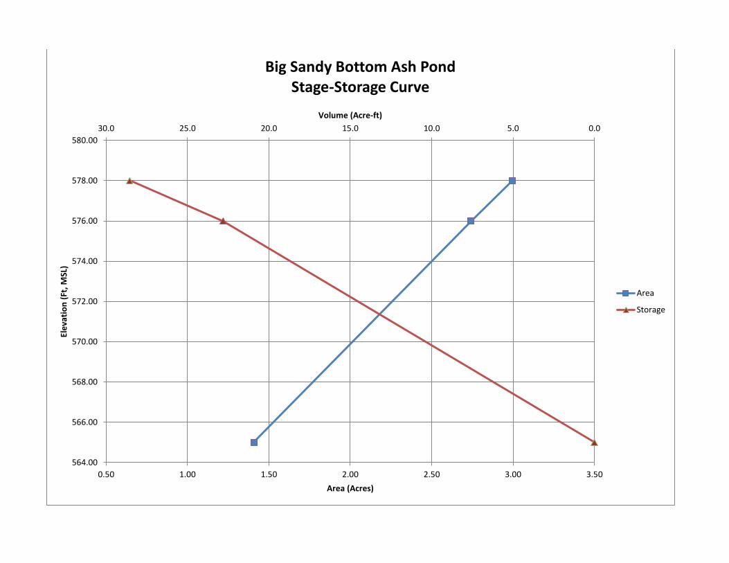
The Bottom Ash Pond has a design capacity of approximately 22 acre-ft (~11 acre-ft per cell) based on an
operating pool elevation of 576. During the course of the year as the ponds are cleaned, the water
level is raised and lowered. Not knowing all operational history the maximum CCR capacity of the
bottom ash pond would have been approx. 30 acre-ft based on top of dike.
4
11.0 FEATURES THAT COULD ADVERSELY AFFECT OPERATION DUE TO
MALFUNCTION OR MIS-OPERATION {(257.73 (c)(1)(vii))} […and any identificable natural or manmade features that could adversely affect operations of
the CCR runit due to malfunction or mis-operation]
In the event of malfunction or mis-operation of any of the pond’s appurtenances the ponds operations
could be adversely affected. These structures include outlet structure and piping between the Bottom
Ash Pond and Clearwater Pond. The malfunction or mis-operation of the adjoining Clearwater and
Reclaim Ponds would limit operations of the Bottom Ash Pond but are unlikely to cause structural
integrity issues for the Bottom Ash Pond.
12.0 DESCRIPTION OF THE TYPE, PURPOSE AND LOCATION OF EXISTING
INSTRUMENTATION {257.73 (C)(1)(VIII)} [A description of the type, purpose, and location of existing instrumentation.]
The Bottom Ash Pond Complex has 3 piezometers located along the perimeter dike. These piezometers
are read on a minimum of every 30 days for the purpose of determining the phreatic water level within
the dike. A location map is provided in Attachment C.
13.0 AREA – CAPACITY CURVES FOR THE CCR UNIT {257.73 (C)(1)(IX)} [Area-capacity curves for the CCR unit.]
An area capacity curve for the Bottom Ash Pond was developed using historical and recent information
and is included in Attachment D.
14.0 DESCRIPTION OF EACH SPILLWAY AND DIVERSION {257.73 (C)(1)(X)} [A description of each spillway and diversion design features and capacities and calculations
used in their determination.]
Water and waste material were discharged into the Bottom Ash Cells from a pipes located on wooden
tressle structure located in each cell. The engineering drawings for the wooden trestle structure are
included in Attachment B.
The outlet for each cell of the Bottom Ash Pond is a 24-in steel standpipe connected to a 24-in pipe that
discharges into the cell of the Clearwater Pond. A metal skimmer structure is located around the drop
outlet to control the discharge of solids from the Bottom Ash Pond. An 12-in steel pipe with a slide
gate is connected to the 24-in discharge pipe to allow dewatering of the bottom ash cell. Additionally,
a 30-in corrugated HDPE plastic pipe is located next to the outfall structure and allows plant personnel
to place a pump to assist with dewatering stored bottom ash. CCR material was periodically excavated
from the Bottom Ash Pond and hauled to the Fly Ash Pond for disposal. The engineering drawings in
Attachment B show a sloping riser as the outfall structures from each Bottom Ash Pond cell. No
drawings are available for the existing structures.
5
The Bottom Ash Pond is primarily an up ground structure with three of the four sides constructed above
ground. Storm water from the north hillside is directed away from the Bottom Ash Pond. Therefore
storm water run-on is limited to that which falls directly on the water surface or the top of the dike.
There are no calculations available for the design of the outflow structure for the Bottom Ash Pond.
15.0 SUMMARY CONSTRUCTION SPECIFICATIONS AND PROVISIONS FOR
SURVEILLANCE, MAINTENANCE AND REPAIR {257.73 (C)(1)(XI)} [The construction specifications and provisions for surveillance, maintenance, and repair of the
CCR unit.]
Construction of the Bottom Ash Pond was completed in around 1971. No engineering design report or
specificationcould be located for the construction of the Bottom Ash Pond. The engineering drawings
are provided in Appendix B.
As required by the CCR rules the Bottom Ash Pond is inspected at least every 7 days by a qualified
person. Also as a requirement of the CCR rules the impoundment is also inspected annual by a
professional engineer. Piezometers are read on a minimum of every 30 days for the purpose of
determining the phreatic water level within the dike.
If repairs are found to be necessary during any inspection they will be completed as needed.
16.0 RECORD OR KNOWLEDGE OF STRUCTURAL INSTABILITY {257.73 (C)(1)(XII)} [Any record or knowledge of the structural instability of the CCR unit.]
Erosion of the interior slope of the bottom ash pond was a problem until the grouted riprap was installed
on the interior in 2010.

ATTACHMENT A
LOCATION MAP
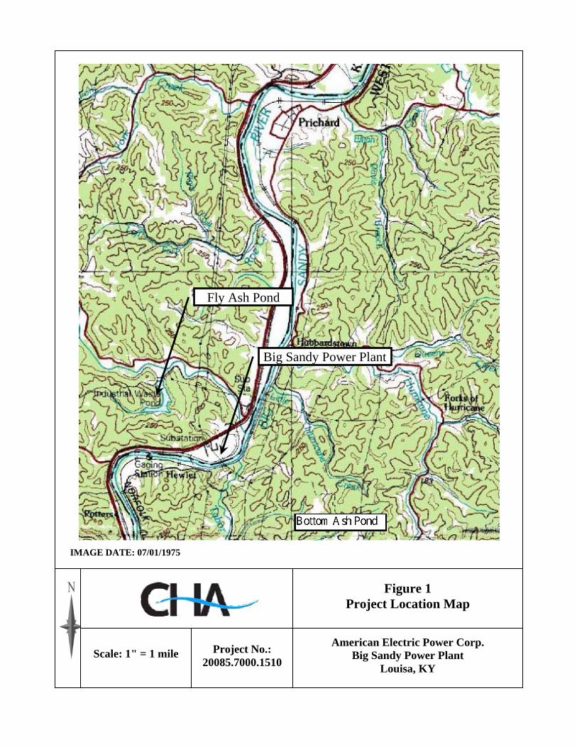
Figure 1 Project Location Map
American Electric Power Corp. Big Sandy Power Plant
Louisa, KY
Scale: 1" = 1 mile Project No.: 20085.7000.1510
Big Sandy Power Plant
IMAGE DATE: 07/01/1975
Fly Ash Pond

ATTACHMENT B
DESIGN DRAWINGS


ATTACHMENT C
INSTRUMENTATION LOCATION MAP

PARKING
PIP
E
PIPE
PIPE
PIPE
PIP
E
PIP
E
CONVEYOR
CONCRETE
CONCRETE
CB
CB
TANK
DENSE WOODS
DENSE WOODS
DENSE WOODS
ELEV:
N:
E:
ID:1302
2107823.02
248405.05
568.40
520
530
540
550
560
520
530
540
550
560
590
590590600610620
630640
650
660670680690
700
590
590
590
580
580
580
570
570
580
580
570
570570
570
568.4
567.1
566.4
565.2
565.7
566.8
566.8
565.3
565.4
565.1
565.6565.4
568.1
566.8
566.6
567.0
566.7567.8
566.8
576.2
572.2
572.9
581.0
571.0
593.2
600.8
570.4
568.3
569.6
566.5
567.0
568.6
566.3
567.3
564.7
561.7
591.6
589.6 593.1
591.2
593.4
591.5
589.9
591.1
591.9
590.6
589.3
589.1
567.8
567.5
568.3
567.9
567.8
572.1
576.8
577.4
588.7
566.7
567.5
568.4
568.4
564.4
564.8
566.2
566.6
565.6
564.6
565.4
564.9
577.6
562.4
572.7
573.5
575.8
574.5
575.0
574.8
568.4
570.8 570.3
566.3
568.2
583.5
581.2
578.2
579.1
583.4
583.7
CONCRETE
CONVEYOR
566.8
567.6
573.3
574.1
578.9
578.4
580
588.5
574.3
574.5
W.E. 564.4
W.E. 574.7
W.E. 561.2
W.E. 562.7
592.5
W.E. 560.4
TOWER
TOWER
W E
N
IMAGERY DATE: MAY 2005
UNIT: US Survey Foot
ZONE: Kentucky State Planes, Northern Zone
DATUM: NORTH AMERICAN DATUM OF 1983 (NAD83)
HORIZONTAL CONTROL:
BOTTOM ASH POND
CLEARWATER POND
RECLAIM POND
DATE:
SCALE:1"=200'
DRN BY:
1 RIVERSIDE PLAZA
COLUMBUS, OH 43215
AEP SERVICE CORP.
DWG NO:FIGURE 1 REV 1BIG SANDY POWER STATION
SHEET 1 OF 3
BOTTOM ASH COMPLEX
PL
OT
DA
TE:9/2/2016
PL
OT
TI
ME:9:5
4:5
6
AM
s252086
BY:
BA2
BA1
BA6
2108000
21
08
00
0
2107500
21
07
50
0
2109000
21
09
00
0
2108500
21
08
50
0
248500 248500
248000 248000
249500 249500
249000 249000

ATTACHMENT D
Stage-Storage Curve
0.05.010.015.020.025.030.0
564.00
566.00
568.00
570.00
572.00
574.00
576.00
578.00
580.00
0.50 1.00 1.50 2.00 2.50 3.00 3.50
Volume (Acre-ft)
Ele
vati
on
(Ft
, MSL
)
Area (Acres)
Big Sandy Bottom Ash Pond Stage-Storage Curve
Area
Storage