Embed Size (px)
Citation preview
HISCO
SENTINEL H SERIES DVR USER MANUAL
2
IIMMPPOORRTTAANNTT SSAAFFEETTYY IINNSSTTRRUUCCTTIIOONNSS
1) Read these instructions
2) Keep these instructions
3) Heed all warnings
4) Follow all instructions
5) Do not use this apparatus near water
6) Clean only with a dry cloth
7) Do not block any of the ventilation openings Install in accordance with the manufacturers instructions
8) Do not install near any heat sources such as radiators heat registers stoves or other apparatus that produce heat
9) Do not defeat the safety purpose of the polarized or grounding type plug
A polarized plug has two blades with one wider than the other
A grounding type plug has two blades and a third grounding prong
The wide blade or the third prong is provided for your safety
When the provided plug does not fit into your outlet consult an electrician for replacement of the obsolete outlet
10) Protect the power cord from being walked on or pinched particularly at plugs convenience receptacles and the point
where they exit from the apparatus
11) Only use the attachmentsaccessories specified by the manufacturer
12) Use only with a cart stand tripod bracket or table specified by the manufacturer or sold with the apparatus
When a cart is used use caution when moving the cartapparatus combination to avoid injury from tip-over
13) Unplug this apparatus during lightning storms or when unused for long periods of time
14) Refer all servicing to qualified service personnel Servicing is required when the apparatus has been damaged in
any way such as power supply
cord or plug is damaged liquid has been spilled or objects have fallen into the apparatus the apparatus has been
exposed to rain or moisture does not operate normally or has been dropped
15) This equipment is indoor use and all the communication wirings are limited to inside of the building
16) The socket-outlet shall be installed near the equipment and shall be easily accessible
17) CAUTION
RISK OF EXPLOSION IF BATTERY IS REPLACED BY AN INCORRECT TYPE
DISPOSE OF USED BATTERIES ACCORDING TO THE INSTRUCTIONS
Operation Max temperature 40
USB Load condition USB Ports( 5 Vdc Max 500 mA)
3
BBEEFFOORREE IINNSSTTAALLLLAATTIIOONN
Installation should be carried out only by qualified personnel and in accordance with any electrical regulations in force
at the time
The DVR must be placed on a stable surface or mounted in an approved cabinet
Adequate ventilation must be provided taking particular care not to block any of the air vents on the DVR
Adequate protection against lightning strikes and power surges must be installed to prevent damage to the DVR
Any safety warnings on the DVR and in these instructions must be adhered to
If cleaning is necessary shutdown the DVR and disconnect power first
Use a soft dry cloth only never use any abrasive cleaners
Do not attempt to service or repair the DVR as opening or removing covers may expose dangerous voltages or other
hazards
Refer all servicing to qualified service personnel
4
MMAAIINN FFEEAATTUURREESS
MOUSE CONTROL
Designed to be controlled and easy to use with a mouse
ENHANCED GRAPHICAL USER INTERFACE [GUI]
The DVR menu structure and on screen display is presented in a simple to use and logical GUI format
GENUINE PENTAPLEX OPERATION
The DVR will continue to record at full frame rate during local playback local setup multi user remote viewing and
playback and remote setup
AUDIO
4 audio inputs are supported which can be assigned to any video channel Live and recorded audio can be monitored
remotely over the internet and remote lsquotalkbackrsquo audio transmission to the DVR is also possible
BACKUP
Recorded footage (including audio) can be archived to USB memory stick or CDDVD
Playback software is embedded with the backup files and the backup also contains the system event log and backup log
for full traceability
REMOTE CONNECTION
Depending on the user level full DVR control is available over the internet as well as the ability to remotely configure the
DVR Alarm outputs on the DVR can be remotely triggered over the internet
COMPREHENSIVE RECORDING SETUP
Recording can be scheduled alarm or motion activated For each type of recording frame rates image quality and audio
recording properties can be adjusted per hour day and for each individual channel
The DVR also has a panic recording feature (from the front panel or external input) which overrides all other recording
settings to provide the best quality recording in the event of an emergency
PTZ CONTROL
Full PTZ control is available from the front panel or remote connection and a wide number of speed dome protocols are
supported Protocols can be set individually for each channel and PTZ speed can be adjusted to suit particular speed
domes
5
MMAAIINN FFEEAATTUURREESS
TELEMETRY CONTROL
Full telemetry control is available from the front panel or remote connection and a wide number of speed dome protocols
are supported Protocols can be set individually for each channel and telemetry speed can be adjusted to suit particular
speed domes
EXTENSIVE MONITOR SUPPORT
The DVR has 4 main monitor outputs (Composite VGA S-Video and HDMI) which can be used simultaneously
Support is also provided for up to 4 spot monitors and each spot monitor output can be programmed in the DVR setup
LIVE DISPLAY
The DVR displays single or multi screen images and also has several sequence modes (standard and user definable)
CONFIGURATION BACKUP
All configuration settings on the DVR can be saved to USB memory stick or a PC file remotely
The saved data can then be uploaded to other DVR units allowing rapid deployment where more than
one DVR is being installed
EMAIL SUPPORT
The DVR can send emails to specific users to notify events such as alarm motion detection
hard drive failure amp etc
6
SSYYSSTTEEMM OORRGGAANNIIZZAATTIIOONN
7
SSYYSSTTEEMM CCOONNFFIIGGUURRAATTIIOONN
1 Front panel description
KEY DESCRIPTION Function Key
POWER Turn OnOff the system power
DISPLAY Selects various display modes in live display and playback
PTZ Selects PTZ mode in live display
SETUP Displays the setup menus
SEARCH Displays the search menu
Control Key
CHANNEL SELECTION
BUTTONS
Used to display individual channels in live display and playback
Also used to enter numeric passwords for the various login screens
CURSOR KEYS Allow to Navigate on the menu
ENTER Apply or Select an item
RETURN Cancel or go to Previous menu
Playback Control
Shuttle Wheel
Used to quickly adjust playback speed and direction
Also used to control camera zoom when in PTZ mode
and digital zoom level in live display
JOG When playback is paused used to move footage forwards or backwards frame
by frame
HOLD Locks the current function of the SHUTTLE WHEEL so it can be released
Increases reverse playback speed
Selects reverse playback
ΙΙ Pauses resumes playback
Selects forward playback and also accesses the instant playback feature
Increases forward playback speed
8
SSYYSSTTEEMM CCOONNFFIIGGUURRAATTIIOONN
2 Rear panel description (4CH)
A VIDEO IN BNC Port for Connection of DVR amp Camera (4 Camera Connectable) LOOP BACK Output DVR Camera Video to Loop Back Port (4 BNC Port)
B MONITOR OUT Output DVR Video to AV Monitor
SPOT OUT Output Spot-out Video to AV Monitor C NTSCPAL Select NTSC or PAL Type D AUDIO OUT Output Audio Data AUDIO IN Audio Input Terminal Related with 1~4 Camera
E DVI OUT Output Video to a Computer Monitor by Connected DVI F ALARM RELAY RS 485 Connect Port for Sensor Relay amp PTZ G USB PORT USB port for use the USB memory stick and USB HDD Backup
ETHERNET (TCPIP) Port for Cross cable (For Remote Surveillance) DC Power Input Power Supply by DC 12V Adaptor
A B C E D F G
9
SSYYSSTTEEMM CCOONNFFIIGGUURRAATTIIOONN
2 Rear panel description (8CH 16CH)
A CAMERA INPUTS and LOOP OUTPUTS Connect up to 16 camera inputs Loop outputs can be used for connection to other equipment
B COMPOSITE AND S-VIDEO MAIN MONITOR CONNECTIONS Both outputs can be used at the same time if more than one main monitor connection is required
C SPOT MONITOR OUTPUTS Up to 4 spot monitors can be connected as necessary
D ALARM INPUTS Up to 16 alarm inputs can be connected and configured as high or low Inputs with common ground
E ALARM OUTPUTS Up to 16 alarm inputs can be connected and configured as high or low outputs with common ground
F RELAY OUTPUTS Up to 4 Relay outputs can be connected and configured as high or low outputs with common ground
G RS485 Can connect PTZ camera and controller by two RS485 connectors Left side for PTZ Right side for keyboard controller H AUDIO INPUTS amp OUTPUTS Up to 4 audio inputs and one audio output can be connected as necessary
I VIDEO SIGNAL SWITCH Can change Video input signal type
USB PORT Can connect USB mouse or USB device for backup
J HDMI Can connect HDMI monitor output
VGA Can connect VGA monitor output
K RS232 Serial port
LAN Can connect to a router or internal network
L POWER Can connect Power cable
K I
J
L
D G
A B C
E F H
10
SSYYSSTTEEMM CCOONNFFIIGGUURREE ndashndash RReemmoottee CCoonnttrroolllleerr
3 Remote Controller description
POWER
System
ONOFF
SETUP Open System Setup Menu
RETURN
Cancel Deselect
Previous Screen
Channel Selection Buttons
If there are many DVRs on stack each DVR must be set with different ID the remote controller sets
each ID per DVR then all DVRs can be controlled with one remote controller by each ID
How to set ID on the remote controller
Press the ID button then displayed INPUT ID statement
Press the set ID and Press the RETURN button (The default ID is 01)
For returning to the original situation press the ID button again
And Input the 255 and press the RETURN button of remote controller
Navigation Buttons
Used for Playback Control
Menu Navigation and PTZFocus Control
ID Button
Select DVR ID
ENTER Apply Select Go to Next Screen
DISP Change display screen
SEARCH Go to Search mode
PTZ Go to PTZ menu
PANIC Record by Panic setting
KEYLOCK Lock the keys (Remote Front)
SEQUENCE Change to Sequence screen
ZOOM Go to Zoom mode
ARCHIVE Go to backup menu
11
CCOONNNNEECCTT ampamp PPOOWWEERR OONN
bull Connect up to 16 CAMERA INPUTS as necessary
The DVR also has LOOP OUTPUTS so that any signals can be fed to other equipment if required
Termination is automatically set by the DVR depending on connection type
bull Connect one or more monitors to the DVR using the COMPOSITE VGA S-VIDEO or HDMI connections
bull Connect power to the DVR The DVR checks for proper power connection and emits two beeps
Press the POWER BUTTON on the front panel of the DVR to begin operation
The DVR startup screen detects and checks the status
of hard drives and the CDRW DVD-RW drive
After startup diagnostics are complete the operator must logon to the
system The default user name is lsquoADMINrsquo
Using the CHANNEL SELECTION buttons key in
the default password of lsquo1234rsquo and press the ENTER button
The DVR begins normal operation and shows the default display
of all 16 channels
The status bar(Include menu control) at the bottom of the screen
shows menu first time After that it will show the current time and
date
A title for each channel is shown
The red square and letter lsquoTrsquo in the top right of each channel
display shows that the channel is recording in Timer Schedule
mode
12
MMEENNUU CCOONNTTRROOLL
All menus can be controlled from above lsquoStatus Barrsquo with mouse or front buttons
LLIIVVEE DDIISSPPLLAAYY DIVISION SCREEN
Select the lsquoDISPLAYrdquo button and screen division menu will appear
Select the screen type (1468916 and rotation sequence)
Sequence mode
User can select the type from display menu
Press the SEQ button Each channel is shown in full screen for a set period of time before switching to the next channel
To stop the sequence on a particular channel press the SEQ button again
More complex sequences can be programmed through the setup menu
13
LLIIVVEE DDIISSPPLLAAYY
1) CAM Select the Channel
2) Sequence If pressing the ldquoSTARTrdquo button after assigning the ldquoPresetrdquo in advance
sequence will be started
3) Position name Input the name after assigning the ldquoPresetrdquo location
4) Avail Position User can see the available Preset location If clicking the ldquoGOTOrdquo
button after selecting it camera will be moved Press the ldquoREMOVErdquo button to delete
the saved Preset location
5) Zoom Focus IRIS User can control each item with + or - button
6) Parameter
Press this button and another window will appear User can select each items from PTZ parameter menu
Digital Zoom
Select the ldquoZOOMrdquo button
When viewing a channel in full screen the operator can zoom in to a particular area by up to 8 times
To use the digital zoom select the required channel and press the ZOOM button
The small window at bottom right shows the full image and the main display area shows the zoomed portion
14
LLIIVVEE DDIISSPPLLAAYY
User can see the current log immediately
Click once after selecting log recorded data will be played This is in case of selecting the ldquoPREVIEWrdquo option)
Panic Recording
This menu is used to start and stop the Panic recording
If the panic recording is started record icon will change to red square with ldquoPrdquo
Select once more to return to previous
- Panic recording setup will be assigned from Record menu
15
LLIIVVEE DDIISSPPLLAAYY Quick Menu
User can use quick menu by clicking the right of the mouse on
each live channel
Click the right of the mouse on live channel that user wants to control
1 Freeze OnOff User can stop the live display of channel that user wants Even though other channels show live
display this particular channel display is stopped Click once more to return to previous
2 PTZ
Please refer to ldquoPTZrdquo menu of Page 13
3 Zoom
Please refer to ldquoZOOMrdquo menu of Page 13
4 Playback
User can playback immediately with selected time (10 20 30 seconds or 1 minute ago)
In case of selecting ldquogo torsquordquo menu this menu will appear
After selecting the time press ldquoOKrdquo
5 Record Start (Stop)
Please refer to ldquoPanic recordrdquo menu of Page 13
16
SSYYSSTTEEMM SSEETTUUPP
Click the ldquoMENUrdquo and click the SYSTEM SETUP menu
To navigate around any items in the setup menu use the CURSOR KEYS and the ENTER and RETURN buttons
In general the ENTER button is used to select and change a particular item and the RETURN button is used to cancel
a change or exit from a particular setup screen
To setup all main system functions highlight SYSTEM SETUP and press ENTER
17
SSYYSSTTEEMM SSEETTUUPP
CAMERA Click the CAMERA menu
CAMERA CAMERA SETUP
To setup the various camera options highlight CAMERA and press ENTER
TITLE Input the camera title
COVERT When it is set to ON the camera image is not displayed in live display but continues to record
AUDIO Determines the audio recording channel
CAMERA COLOR SETUP
Brightness contrast tint and color can be adjusted for each individual channel
Highlight each channel to modify and press ENTER
18
SSYYSSTTEEMM SSEETTUUPP
Click each value with button
The selected channel is displayed in full screen
BRIGHTNESS CONTRAST TINT and COLOR can be changed as necessary
To modify a different channel highlight CAMERA and choose the desired channel
Press RETURN when all changes are complete
CAMERA PTZ SETUP
Click the PTZ SETUP menu and click each value
on the ADDRESS PROTOCOL and BAUD RATE
menu
Change each value with button
ADDRESS The unique ID of the PTZ device
PROTOCOL The protocol of the PTZ device
BAUD RATE The baud rate of the PTZ device
DETAIL Detail setting for PTZ device (Refer to the next page)
TOUR Tour setting for PTZ device (Refer to the next page)
19
SSYYSSTTEEMM SSEETTUUPP
Click the ldquoDETAILrdquo button and change the detail value with button
Note that some settings such as AUTO FOCUS may not be compatible with particular
PTZ equipment
If this is the case changing the value will have no effect on PTZ control
Click the ldquoTOURrdquo button and set the MODE to [AUTO] to use TOUR function
First of all please set PRESET number on the live PTZ mode
Then set the PRESET number 1 to 16 and DWELL Time
DWELL TIME means staying time on position until move next preset position
20
SSYYSSTTEEMM SSEETTUUPP
CAMERA MOTION SENSOR
Click the MOTION SENSOR menu and click the
value on the SENSITIVITY menu
Change the value with button
SENSITIVITY Between 1 (Lowest) and 10 (Highest) and determines the degree of motion required before recording is
activated
Click the AREA SETUP button
AREA SETUP Choosing this option allows the operator to define which areas of the image are monitored for motion
detection
For quick select or deselect the entire grid
click the right mouse button and click the SELECT ALL or DESELECT ALL menu
- Red line area Selected area
- White line area Non selected area
21
SSYYSSTTEEMM SSEETTUUPP DISPLAY To setup the various display options highlight DISPLAY and press ENTER
DISPLAY - OSD
Click the OSD menu
Then click the button for ONOFF and change
the value
STATUS BAR Determines the time to turn from the menu of status bar to time display
CAMERA TITLE Determines whether the camera title is displayed
RECORDING MODE ICON Determines whether the DVR recording status is shown at the top right of each channel
display window
BORDER Determines whether there is a border around each channel in multi screen display mode
BORDER COLOR If the border is ON the operator can choose the color
MOTION SENSOR DISPLAY If false motion recording is occurring the operator can use this feature to determine and
rectify the cause in real-time
OFF ndash normal display mode
ON ndash areas where motion is detected are highlighted with colored blocks
MOTION COLOR The color of the blocks displayed when MOTION SENSOR DISPLAY is set to ON
LANGUAGE Determines the language type
22
SSYYSSTTEEMM SSEETTUUPP
DISPLAY MONITOR
Click the MONITOR menu
Then click the button for ONOFF and change
the value
SEQUENCE DWELL The time each screen is displayed in a sequence operation
SPOT DWELL The time each screen is displayed on the spot monitor outputs
DE-INTERLACE MODE When recording any channels in D1 resolution (704 x 576) this should be set to ON to prevent
shudder during playback
ALARM POP-UP MODE When set to ON an alarm input will cause the associated channel to display in full screen
ALARM POP-UP DWELL Determines how long the full screen popup is displayed after an alarm input If the alarm
condition continues the popup screen is displayed constantly
MOTION POP-UP MODE When set to ON motion detection will cause the associated channel to display full screen
MOTION POP-UP DWELL Determines how long the full screen popup is displayed after motion detection If motion
continues the popup screen is displayed constantly
23
SSYYSSTTEEMM SSEETTUUPP
DISPLAY SEQUENCE
Click the SEQUENCE menu
When the SEQ button is pressed the default sequence will cycle through all 16 channels one by one
Sequence setup allows the operator to define a custom sequence using mixed multi screen views and any desired
channels
Click the ADD menu
To add a new sequence highlight ADD and press ENTER
Sequence title is highlighted ndash press ENTER to bring up the virtual keyboard and key in a name or reference number for
the new sequence
Click on the ACTIVATION tab and click button for select ONOFF
Select the SAVE Then below menu will appear
24
SSYYSSTTEEMM SSEETTUUPP
Press ADD Then ldquoSequence Setuprdquo menu appears
Determine the ldquoVIEW TYPErdquo and assign ldquoCONFIGURErdquo Then click CONFIRM
To add an additional mode click ADD continuously After finishing the setup press CLOSE
To modify the current one double click that mode Then lsquoSequence Setuprdquo window will appear again
The new sequence is now saved and can be started by pressing the SEQ button when in live view
25
SSYYSSTTEEMM SSEETTUUPP
DISPLAY SPOT-OUT
Click the SPOT-OUT menu and click the camera
channel for ONOFF
The DVR has 4 SPOT MONITOR OUTPUTS
User can assign the SPOT OUT display for each channel
Double click the spot out channel that requires to be assigned
SPOT TITLE input the title
ACTIVATION Determines ONOFF
Press MODIFY (Below is default setup)
To modify the current display double click the display Then lsquoSpot Sequence Setuprdquo window will appear
How to setup is same as Sequence setup (User can assign Single and Quad display only)
To add the additional display press ADD
26
SSYYSSTTEEMM SSEETTUUPP
SOUND Click the SOUND menu
To setup the various sound options highlight SOUND and press ENTER
SOUND AUDIO
Click the AUDIO menu and click the ONOFF menu
Then click the button for ONOFF
LIVE AUDIO When it is set to ON the selected audio channel can be monitored on the AUDIO OUTPUT
AUDIO MONITORING CHANNEL Specify which one of the 4 AUDIO INPUTS is routed to the AUDIO OUTPUT
NETWORK AUDIO TX When set to ON live and playback audio is transmitted to a remote PC connection
NETWORK AUDIO RX When set to ON allows a remote PC connection to send audio back to the DVR
SOUND BUZZER
Click the BUZZER menu and click the ONOFF menu
Then click the button for ONOFF
KEYPAD When it is set to ON each front panel button press is confirmed by a beep
27
SSYYSSTTEEMM SSEETTUUPP
SYSTEM Click the SYSTEM menu
To setup the various system options highlight SYSTEM and press ENTER
DATE TIME
Click the DATE TIME menu
DATE TIME Allows the operator to set or modify the current date amp time
DATE FORMAT Determines how the date is displayed
TIME FORMAT Determines how the time is displayed
NETWORK TIME SERVER SETUP If the DVR is connected to the Internet the time and date can be accurately set by
selecting SYNC and pressing ENTER
TIME ZONE SETUP It should be set according to the region which the DVR is used in
DST When it is set to ON the DVR will automatically adjust the time by one hour on the relevant date in spring
and autumn
28
SSYYSSTTEEMM SSEETTUUPP
SYSTEM SYSTEM MANAGEMENT
Click the SYSTEM MANAGEMENT menu
SYSTEM INFORMATION User can see the system information as below
FW version Shows the firmware version of the DVR
HW version Shows the hardware version of the DVR
VIDEO SIGNAL TYPE The DVR automatically switches between PAL and NTSC depending on the channel 1 input
signal at power on
DISK CAPACITY The first value shows the amount of hard drive capacity used by recorded footage the second value
shows the total hard drive capacity installed
IP ADDRESS Shows either the manual IP address entered in NETWORK setup or the IP address assigned by a DHCP
server if enabled
MAC ADDRESS Shows the MAC (Media Access Control) address of the DVR
It is unique ndash no other network device has this MAC address
DDNS DOMAIN NAME If DDNS is enabled the host DDNS server is specified here
NET CLIENT PORT The port number that the DVR uses to support remote connection from the client software
WEB SERVER PORT The port number that the DVR uses to support remote connection from Internet Explorer
or other web browsers
29
SSYYSSTTEEMM SSEETTUUPP
SYSTEM NAME It is used so that notification emails can be identified
FW UPDATE Firmware updates may be released periodically to enhance system performance and add extra features
The operator can upgrade the firmware using a USB memory stick
After inserting the FW in USB or CDDVD Press UPDATE Then below menu will appear
After selecting the FW from FW list press UPGRADE
Then FW upgrade is started
FACTORY DEFAULT If settings have been changed which cause erratic behavior the factory default settings
can be loaded
SYSTEM DATA System settings can be saved to a USB memory stick The settings can be reloaded
in case of accidental factory reset or can be transferred to another DVR if multiple
units need to be installed with the same settings All information is saved apart from
network settings and system name
PASSWORD Determines the PASSWORD ONOFF to enter specific menu
SYSTEM CONTROL DEVICE
This will allow up to 254 DVRs to be controlled from the same keyboard
SYSTEM ID If more than one DVR is connected on the same RS485 bus each one must have a unique ID
Note If using more than one DVR on stack each DVR must have a unique ID for control by remote controller
PROTOCOL Must be set by Control Device
BAUD RATE Must be set to match the baud rate of the PTZ controller
30
SSYYSSTTEEMM SSEETTUUPP
USER Click the USER menu
To setup the various system options highlight USER and press ENTER
USER USER MANAGEMENT
By default the DVR is configured with a user ID of ADMIN belonging to the ADMIN group and with a password of 1234
As well as the ability to add new users existing user details can be modified
To modify user details highlight the user with the green cursor and press ENTER
The maximum number of users that can be created is 8
For editing double click on the each tab
After changing click OK
USER ID Edit the user ID using the virtual keyboard (Max 10 characters)
PASSWORD Change the password using the virtual keyboard (Max 4 Characters)
GROUP Users can be assigned to one of three groups - ADMIN MANAGER or USER
E-MAIL Enter the userrsquos email address if email notification is required (Max 64 Characters)
E-MAIL NOTIFICATION Enable or disable email notifications for the specified user
31
SSYYSSTTEEMM SSEETTUUPP
For ADD double click on the each tap after clicking ADD
After changing click OK
USER ID Edit the user ID using the virtual keyboard
PASSWORD Change the password using the virtual keyboard
GROUP Users can be assigned to one of three groups - ADMIN MANAGER or USER
E-MAIL Enter the userrsquos email address if email notification is required
E-MAIL NOTIFICATION Enable or disable email notifications for the specified user
USER USER AUTHORITY
User can give the authority to the MANAGER and USER
To select authority click the APPLY button after selecting each item
Please note Any user can be deleted except the default ADMIN user
USER LOG OUT
AUTO LOGOUT Determines the AUTO LOGOUT ONOFF
DURATION In case of selecting AUTO LOGOUT ON determines the duration
32
SSYYSSTTEEMM SSEETTUUPP
NETWORK Click the NETWORK menu and determine each value
NETWORK IP SETUP
Click the IP SETUP menu
DHCP When enabled the DVR will obtain an IP address automatically if it is connected to a DHCP server or router
WEB SERVICE When enabled it allows remote connections using Internet Explorer or other web browsers
IP ADDRESS If DHCP is not being used the IP address can be manually set
GATEWAY If DHCP is not being used the gateway IP address can be manually set
SUBNET MASK If DHCP is not being used the subnet mask can be manually set
1ST DNS SERVER If DHCP is not being used the first DNS server can be manually set
2ND DNS SERVER If DHCP is not being used the second DNS server can be manually set
RTSP SERVICE PORT If connected Router support UPampP (Universal plug and play) function
when you click the AUTO PORT the port forwarding is automatically setup
And also can delete the port amp test the port whether working or not
WEB SERVER PORT If connected Router support UPNP (Universal plug and play) function
when you click the AUTO PORT the port forwarding is automatically setup
And also can delete the port
The port number that the DVR uses to support remote connection from Internet Explorer
or other web browsers
ALIAS When you enter the DDNS HOST NAME in DDNS setup (Next page) you can see the information like below
ex) 1234dvrlinknet8080
MAX TX SPEED Specifies the maximum bandwidth that the DVR can use during a remote connection
33
SSYYSSTTEEMM SSEETTUUPP
NETWORK DDNS
DDNS When enabled the DVR can be accessed through a Dynamic DNS server
Commonly used if a broadband connection does not have a static IP address
CAUTION
To use DDNS function User have to port forwarding
a Default WEB SERVICE PORT 8080
b Default RTSP SERVICE PORT 554
Default DDNS HOST NAME is Mac Address so user can connect by two different way
(Mac address Own host name)
a 00115ff00213dvrlinknet
b 1234dvrlinknet User can enter any DDNS Host name
NETWORK E-MAIL
Click the E-MAIL menu
SERVER The SMTP outbound email server that should be used to send email notifications
PORT The outbound email port number
SECURITY Set to OFF if the SERVER does not require a username and password to connect
USER Enter a username to identify the DVR in email messages
PASSWORD If SECURITY is set to ON enter the password here
FROM Input the E-mail address or any text It is only used for E-mail test (E-mail sender)
TEST E-MAIL User can test after inputting E-mail address to receiving test E-mail
34
SSYYSSTTEEMM SSEETTUUPP
EVENT SENSOR Click the EVENT SENSOR menu
To setup the various event handling options highlight EVENTSENSOR and press ENTER
EVENT SENSOR HDD EVENT
Click the HDD EVENT menu
The DVR can monitor the hard drives and detect problems that may be developing
SMART ALARM Enables SMART disk monitoring
CHECK INTERVAL Can be adjusted as desired
DISK FULL EVENT Determines ONOFF
EVENT SENSOR ALARM INPUT
Click the ALARM INPUT menu and
click the OPERATION and TYPE value
Determines the behavior of each of the 816 alarm inputs
OPERATION Alarm inputs can be enabled or disabled
TYPE Alarm inputs can be set as normally open or closed
35
SSYYSSTTEEMM SSEETTUUPP
EVENT SENSOR ALARM OUTPUT
Click the ALARM OUTPUT menu and click each value
Determines the behavior and actions that will trigger each of the 816 alarm outputs
Behavior settings
ALARM OUT Choose which alarm output to configure
OPERATION The selected alarm output can be enabled or disabled
MODE Can be either TRANSPARENT (the output is active only when the trigger criteria is present)
or LATCHED (the output is active for a set period of time after a trigger)
DURATION In LATCHED mode the time that the alarm output remains active after it has been triggered
TYPE Can be set to high (0V to +5V when activated) or low (+5V to 0V when activated)
HDD EVENT Determines whether a hard drive event triggers the alarm output
Action settings
ALARM Determines whether alarm inputs will trigger the alarm output
VIDEO LOSS Determines whether video loss on any of the selected channels will trigger the alarm output
MOTION Determines whether motion detection on any of the selected channels will trigger the alarm output
Remember to select APPLY and press ENTER to save all settings before exiting these menus
36
SSYYSSTTEEMM SSEETTUUPP
EVENT SENSOR BUZZER OUT
Click the BUZZER OUTPUT menu and click each value
Determines the behavior and actions that will trigger the internal buzzer
Behavior settings OPERATION The internal buzzer can be enabled or disabled
HDD EVENT Determines whether a hard drive event sounds the buzzer
MODE Can be either TRANSPARENT (the buzzer sounds only when the trigger criteria is present)
or LATCHED (the buzzer sounds for a set period of time after the trigger)
DURATION In LATCHED mode the time that the buzzer sounds after it has been triggered
Action settings ALARM Determines whether alarm inputs will sound the buzzer
VIDEO LOSS Determines whether video loss on any of the selected channels will sound the buzzer
MOTION Determines whether motion detection on any of the selected channels will sound the buzzer
Remember to select APPLY and press ENTER to save all settings before exiting these menus
37
SSYYSSTTEEMM SSEETTUUPP
EVENT SENSOR EMAIL NOTIFICATION
Click the EMAIL NOTIFICATION menu and
click each value
Determines the behavior and actions that will send an email to a remote user
Behavior settings NOTIFICATION Email notification can be turned ON or OFF
SETUP CHANGE Determines whether a setup change sends an email
HDD EVENT Determines whether a hard drive event sends an email
BOOTING EVENT Determines whether a booting event sends an email
Action settings ALARM Determines whether alarm inputs will send an email
VIDEO LOSS Determines whether video loss on any of the selected channels will send an email
MOTION Determines whether motion detection on any of the selected channels will send an email
FREQUENCY E-mail sending period (Max 60 MIN)
Email settings must also be configured in MAIL and USER MANAGEMENT from
USER MANAGEMENT menu
38
SSYYSSTTEEMM SSEETTUUPP
DISK MANAGE
Click the DISK MANAGEMENT menu
To manage the internal hard drives highlight DISK MANAGE and press ENTER
RECORD TIME LIMIT In certain circumstances it may be necessary to limit the amount of footage stored on the DVR
(to comply with data protection laws for example)
Recording can be limited to 12 hours 1 day 2 days 3 days 1 week or one month
Once the DVR has this amount of footage stored it will start to overwrite the earliest recorded
footage
OVERWRITE When set to ON the DVR will start overwriting the earliest recorded footage once the hard drive
becomes full In this case the percentage of hard drive used shown in live display will always be 99
When it is set to OFF the DVR will stop recording when the disk becomes full
FORMAT If necessary all footage can be erased from the DVR using this option
Please note When a RECORD TIME LIMIT is set the OVERWRITE option cannot be changed
39
RREECCOORRDD MMEENNUU
RECORD MENU
Click the ldquoMENUrdquo
Input the password Then main menu will appear
Click the RECORD menu
To setup the recording behavior of the DVR highlight RECORD MENU and press ENTER
RECORD RECORDING OPERATIONS
Click the RECORDING OPERATION menu and
click each value
Then click the value with button to change
SCHEDULE MODE Either DAILY (one schedule will apply to every day of the week) or
WEEKLY (each day of the week has its own schedule)
PRE EVENT RECORDING TIME When the DVR is not in continuous recording mode this setting determines the
amount of time that is always recorded before an event occurs
(motion detection alarm input etc)
POST EVENT RECORDING TIME When the DVR is not in continuous recording mode this setting determines the
amount of time that is always recorded after an event occurs
(motion detection alarm input etc)
40
RREECCOORRDD MMEENNUU
RECORD CONTINUOUSMOTION
Click the CONTINUOUSMOTION SETUP menu
This setup screen allows the operator to configure scheduled and motion detection recording
There are 2 sections
SIZEFPSQUALITY Recording settings for each channel can be defined across a 24 hour period
in blocks (for example between 0900 and 1800) or for each individual hour
Note that when SCHEDULE MODE is set to WEEKLY each day of the week can also be selected
A CTIVATION This section determines at what times the DVR will record and whether it is in continuous recording
or motion detection
SIZEFPSQUALITY
Click the SIZEFPSQUALITY menu
To change the SIZEFPSQUALITY highlight CONTINUOUSMOTION SETUP and press ENTER
Ensure the SIZEFPSQUALITY is highlighted in yellow and press ENTER again
The 24 hour time bar is highlighted in green
41
RREECCOORRDD MMEENNUU
Click the TIME BAR that user wants to have
the values changed
Press ENTER to display the green cursor
The green cursor shown represents one hour
The table below the time bar shows the recording settings for this time period
Drag the time that user wants to have
the values changed
Example To change the recording settings between 0900 and 1800
Use the CURSOR KEYS to move the green cursor to the 0900 position and press ENTER
The cursor changes to orange to show the start position
Use the CURSOR KEYS to stretch the orange cursor across to the 1800 position
42
RREECCOORRDD MMEENNUU
Click the SIZE FPS QUALITY and AUDIO value
Then click the value with button to change
Press ENTER Recording settings for the selected time period are displayed
16 channels are divided into two groups Maximum recording frame rate for each group is 480FPS at resolution of 1CIF
(352x240)
4 channels can be recorded in full D1 (4CIF704x480) resolution maximum 2 channels from each group
SIZE Recording resolutions of 352x240 704x240 or 704x480(NTSC) can be selected for each channel
FPS Frame rates between 1 and 30 can be set for each channel
QUALITY Four different picture recording qualities can be set for each channel
AUDIO If audio devices are connected to the DVR user can select the audio recording onoff
any audio channel can be assigned to any of the video channels Please refer to camera setup menu
During playback when a particular channel is selected in full screen the assigned audio channel will be played back at
the same time
Adjust values as desired and select OK to finish and return to the parameter menu
Other time periods can be configured in the same manner
Remember that if SCHEDULE MODE is set to WEEKLY recording settings need to be changed for each day
as well as for each particular time
Note The DVR supports a maximum recording rate across all channels of 480 frames per second at 352x240
resolution As settings are adjusted the lsquoframes availablersquo at bottom left displays the number of
available frames still remaining and must always be zero or higher
If while changing recording settings this figure becomes negative recording resolutions
and or frame rates must be lowered to increase the lsquoframes availablersquo value to zero or above
43
RREECCOORRDD MMEENNUU
ACTIVATION
Click the ACTIVATION menu
To change ACTIVATION settings highlight CONTINUOUSMOTION RECORDING and press ENTER
Use the CURSOR KEYS to highlight ACTIVATION and press ENTER
The schedule box is highlighted in green
Drag the Time and Channel with left mouse click
After selecting the area determines the recording type
The schedule screen has 4 symbols to show the different recording modes
NO COLOR blocks No scheduled or motion recording
SKY BLUE blocks The DVR will record continuously
BLUE block The DVR will only record while motion is detected
PINK block The DVR will record continuously and with motion event
44
RREECCOORRDD MMEENNUU
RECORD ALARM SETUP
Click the ALARM RECORDING menu
The setup is the same as CONTINUOUSMOTION
RECORDING
This setup screen allows the operator to configure alarm input activated recording
SIZEFPSQUALITY Recording settings for each channel can be defined across a 24 hour period
in blocks (for example between 0900 and 1800) or for each individual hour
Note that when SCHEDULE MODE is set to WEEKLY each day of the week can also be selected
ACTIVATION This section determines at what times the DVR will monitor the alarm inputs and activate recording
Please refer to Continuous Motion setup on setting up SIZEFPSQUALITY and ACTIVATION
Alarm activated recording can be used in conjunction with Continuous motion recording
For example the DVR could be configured to record continuously at a low frame rate (set in
Continuous Motion Recording) and then increase to a higher frame rate during an alarm input (set in
alarm setup)
45
RREECCOORRDD MMEENNUU
RECORD PANIC SETUP
Click the PANIC RECORDING menu
Select the Size Frame Quality and audio
During panic recording mode the DVR will override all other recording settings and record continuously on all channels
at the settings configured here
46
SSEEAARRCCHH
SEARCH
To search for a particular section of recorded footage press the SEARCH button
To protect unauthorized viewing of footage only ADMIN and MANAGER user levels can playback footage
To login as ADMIN enter the default password of 1234 and press ENTER
SEARCH TIME SEARCH
Click the date that user wants to have the values
changed
The DVR uses a calendar and timeline search method for quick access to recorded footage
The calendar displayed on the left shows the current month
Days highlighted in yellow have recorded footage
The timeline on the right shows a 24 hour status of all channels for the selected day
The recorded time will be displayed with different color on each recording type
Panic White
Motion Green
Continuous Sky blue
Alarm Red
47
SSEEAARRCCHH
Drag the time bar with left mouse click
Press ENTER to select the calendar and use the CURSOR KEYS to move to the required day
As different days are selected the timeline display also changes to show recorded footage on that day
Press ENTER to choose the day and move to the timeline
Click the
PANO(Thumbnail mode)
PLAY(Multi View)
buttons
Use the CURSOR KEYS to move the timeline cursor left or right to select the time segment required
The currently selected time is displayed under the calendar
Press PLAY to begin playback from the selected time
48
SSEEAARRCCHH
SEARCH MODE PANO
PANO( Thumb nail)
Each Screen show s 3 hour data
CH1 0~3 Orsquoclock
CH2 3~6 Orsquoclock
CH8 21~24 Orsquoclock
User can select different channels and playback with
faster speed of up to x64
SEARCH MODE Multi Playback
PLAY(Multi view)
The default playback mode is 16 screen display
By pressing DISPLAY or using the CHANNEL
SELECTION buttons it is possible to display single
screen or other multi screen formats in a similar way to
the live display mode
During playback turning the SHUTTLE WHEEL steadily
clockwise increases the playback speed by up to 64 times
Turning steadily counter-clockwise will reverse play by up
to 64 times When the SHUTTLE WHEEL is released
playback is paused
If the HOLD button is pressed and released during
SHUTTLE WHEEL operation the last shuttle function
is held even if the wheel is released
When playback is paused the JOG RING can be used to
accurately move the footage forward or backwards frame
by frame
Playback speed and direction can also be controlled using
the five playback buttons located under the jog wheel
49
SSEEAARRCCHH
During playback user can reserve the recorded data that needs to be archived
Press button at the time the archive is to be started Then playback is stopped and menu below will appear
After inputting ldquoTAGrdquo name press START Then display is returned to playback
Press button again to end archiving Then menu below will appear again
RESERVE Press this to reserve current data
CONTINUE Press this to reserve more data Then display will return to playback
STOP Make sure to press this button to reserve current data first Then user can select RESERVE
START Press this to start the reserve
CLOSE Finish archiving
Reserved data will be reserved on HDD User can see the reserved data from ldquoRESERVED DATA
MANAGEMENTrdquo on ARCHIVING menu
50
SSEEAARRCCHH
To exit playback mode and return to the search
screen to choose another time and date press
RETURN
To exit the search screen and go back to live view
repeatedly press RETURN
SEARCH EVENT SEARCH
The DVR event log stores events such as motion and
alarm activated recording video loss etc
To search for an event and playback the recorded
footage press the SEARCH button and log in as
ADMIN with the default password of 1234
Click the SEARCH BY EVENT menu and select each
desired channel and condition
Then click the time with button to change
Click the SEARCH button
51
SSEEAARRCCHH
To playback footage for a particular event select the event from the list using the CURSOR KEYS and press ENTER
Playback resumes from the moment when the selected event occurred and continues until stopped by the operator
During event search playback the SHUTTLE WHEEL JOG RING and playback buttons can be used as normal
To stop playback and return to live view mode repeatedly press RETURN
52
AARRCCHHIIVVIINNGG
NEW ARCHIVING
To archive recorded footage to USB memory stick or CDDVD press the ARCHIVE button
To protect unauthorized viewing and distribution of footage only the ADMIN user level can archive footage
To login as ADMIN enter the default password of 1234 and press ENTER
Click each desired channel
Then click the times with button to change
Click the QUERY menu
Make sure to press QUERY first before selecting BURN or RESERVE
Press RELEASE to reset after QUERY
RESERVE Press this after inputting the TAG name
OR
BURN Press this after inputting the TAG name Then press START after menu below appears
53
AARRCCHHIIVVIINNGG
RESERVED DATA MANAGEMENT
AVI ARCHIVING LIST User can see the AVI archiving data that was reserved from new archiving menu
or archiving of search
INFORMATION The detailed information of Reserved AVI data
DELETE User can delete the reserved AVI data
BURN Backup the selected AVI data
54
WWEEBB CCOONNNNEECCTTIIOONN SSEETTUUPP
PRELIMINARY BEFORE CONNECT For using web connection 554 and 8080 ports should be done port forwarding set in Router
Refer the manual of Router for port forwarding setting
WEB RA MINIMUM PC REQUIREMENT
CPU P4 30 or Higher
RAM 512MB or Higher
VGA Geforce MS 400 Radeon 7500 or higher
Gefore 8 series or higher
VGA MEMORY 64MB
MONITOR 1280X1024
OS WINDOW XP2
IE VERSION IE60 or higher
NETWORK 100Mbps
DIRECT X V70 or higher
HOW TO CONNECT Input the IP Address or URL of the DVR in the Internet Explorer Address Bar
When user uses the DDNS service input the URL as below
http1234dvrlinknet8080 (webport 8080) or
http1234dvrlinknet (webport
80)
55
Default ID and password are lsquoADMINrsquo amprsquo1234rsquo
User need to install Active-X click Run Add-on
In case of unable to install active-X User needs to check the option of activeX on IE security menu
Select Enable for all ActiveX related options
(ex Download signed ActiveX control Download unsigned ActiveX controlhellip)
56
WWEEBB CCOONNNNEECCTTIIOONN SSEETTUUPP LIVE MODE
Explanation for function LIVE mode
Select live division screen (1 4 8916 split mode)
Sequence mode
Move to next camera
Full screen
Select live channel ndash select a channel manually
Activate Mic to send a sound to DVR
OnOff Sound from DVR
Save the live image
Print the current screen
Snapshot the current screen
Setup [Render] and [Save Folder]
bull Status Show active status of DVR 1 Alarm ndash Indicator will be marked when system detects Alarm input
57
2 Motion- Indicator will be marked when system detects Motion
3 Video Loss - Indicator will be marked when system detects Alarm input
4 Recording ndash Display current recording mode
(T Continuous M Motion A Alarm recoding)
5 Alarm Out - Indicator will be marked when system detect Alarm output
6 Refresh Time ndash set interval of refresh or Reload for manual refresh
bull Log Display all system logs with real time
bull PTZ User allow to control connected PTZ camera
1 Pattern ndash move a camera among several preset position
2 Preset ndash set a position of camera view
3 Swing ndash move a camera between two preset point
SEARCH (By time line)
58
1 Select a time line on time table or set a exact time
2 Then press lsquoPlayrsquo button
1 Refresh Refresh the recording table of data
2 Play Start to display the recorded data from system
3 Backup User can backup the recorded data on remote site
59
SEARCH (By event)
1 Event Select events for querying
2 Period Set duration for querying recording data
3 Search Start to query and list up all events on the list
4 Select a event on the list then DVR starting to playback the related camerarsquos image
SETUP MODE
60
1 CAMERMA
user can configure camerarsquos attribute such as title live color PTZ setup or motion
Motion setup for detecting motion events
1) Select Motion menu tab
2) Select a channel and sensitivity
61
3) Drag a mouse on image for select detecting area
4) Press OK
2 Display
1) OSD ndash User allow to choose text display items over the image
2) Monitor - user can set dwell time for sequence or spot and pop up function
3 Sound
1) Audio Setting ndash Select a live audio channel and activation
2) Buzzer setting ndash Activate buzzer out for event notification
62
4 System
User can configurable DATE of system check system information and set controller
5 Recording
User can configure the recording parameter
Setting detail is same as system
6 User
Allow to add user select Authority level and Log out time
63
7 Network
User can check the systemrsquos network information and selectable speed level But IP settings are not allowed to
change on remote site
Network IP only can set on system
For email notification user can input the SMTP server detail on below setup
8 Sensor
Management can set all device option of Alarm inout Buzzer out for event notification
64
(HDD EVENT Alarm Input Alarm output Buzzer Out E-mail notification option)
All detail setup follow DVR system setup
INFORMATION Display Model name of DVR and WEB Remote Software version
WWAATTEERRAARRKK PPRROOCCEESSSS
65
1 Open the backup data from device and Run the [bplayer] which is included in the backup folder
2 Click the [Open file] button and open the backup file
3 After open it can see the following message then click the [Yes] button
4 If the backuped AVI file is modified [Verification failed] message will be appeared
SSMMAARRTTPPHHOONNEE CCOONNNNEECCTTIIOONN
66
clubs I-PHONE
1 Select the Safari browser 2 Enter the IP address or URL to connect
And Click the [GO] button
3 Enter the User name and Password then use can see the Image
(Default ADMIN 1234)
67
clubs Black Berry
1 Select the Web browser 2 Enter the IP address or URL to connect
And press the Enter button
3 Enter the User name and Password then use can see the Image
(Default ADMIN 1234)
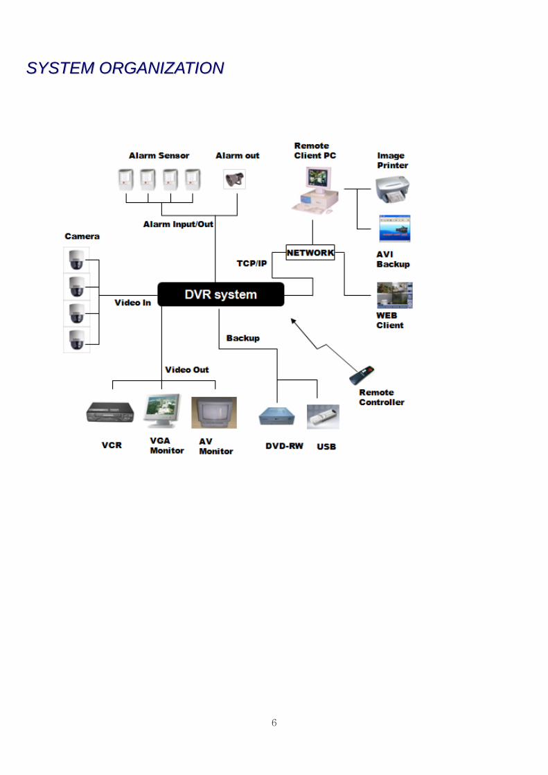
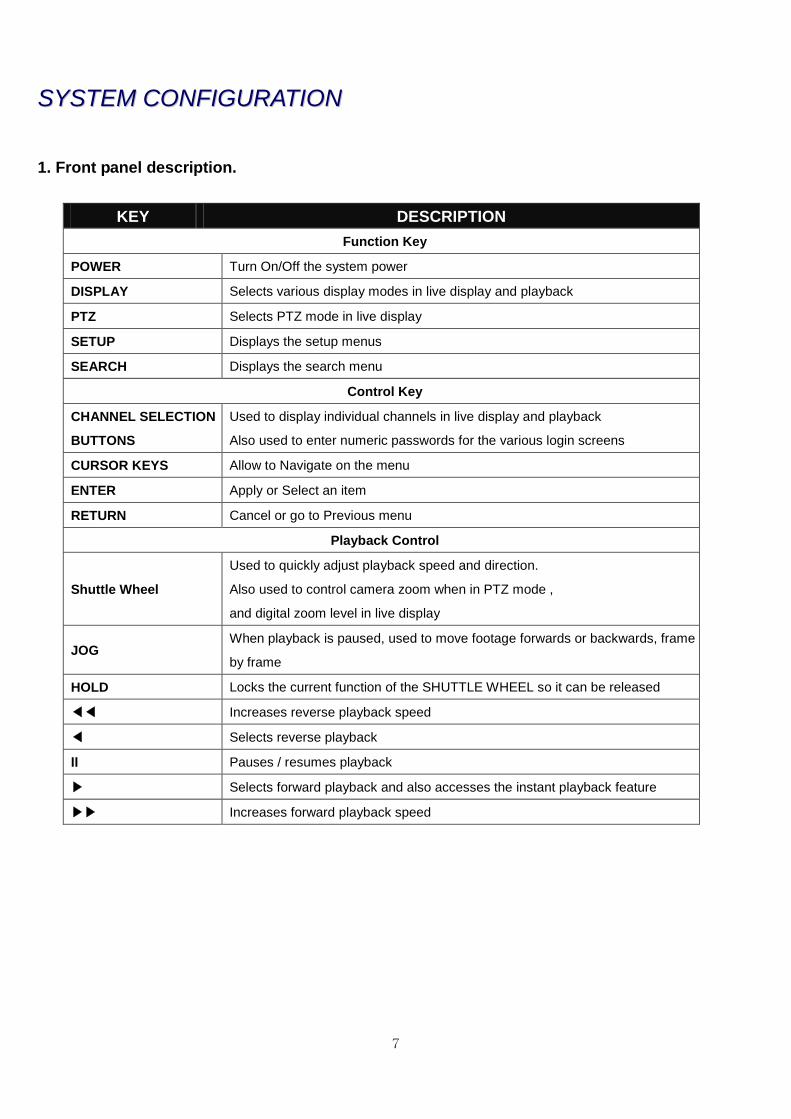
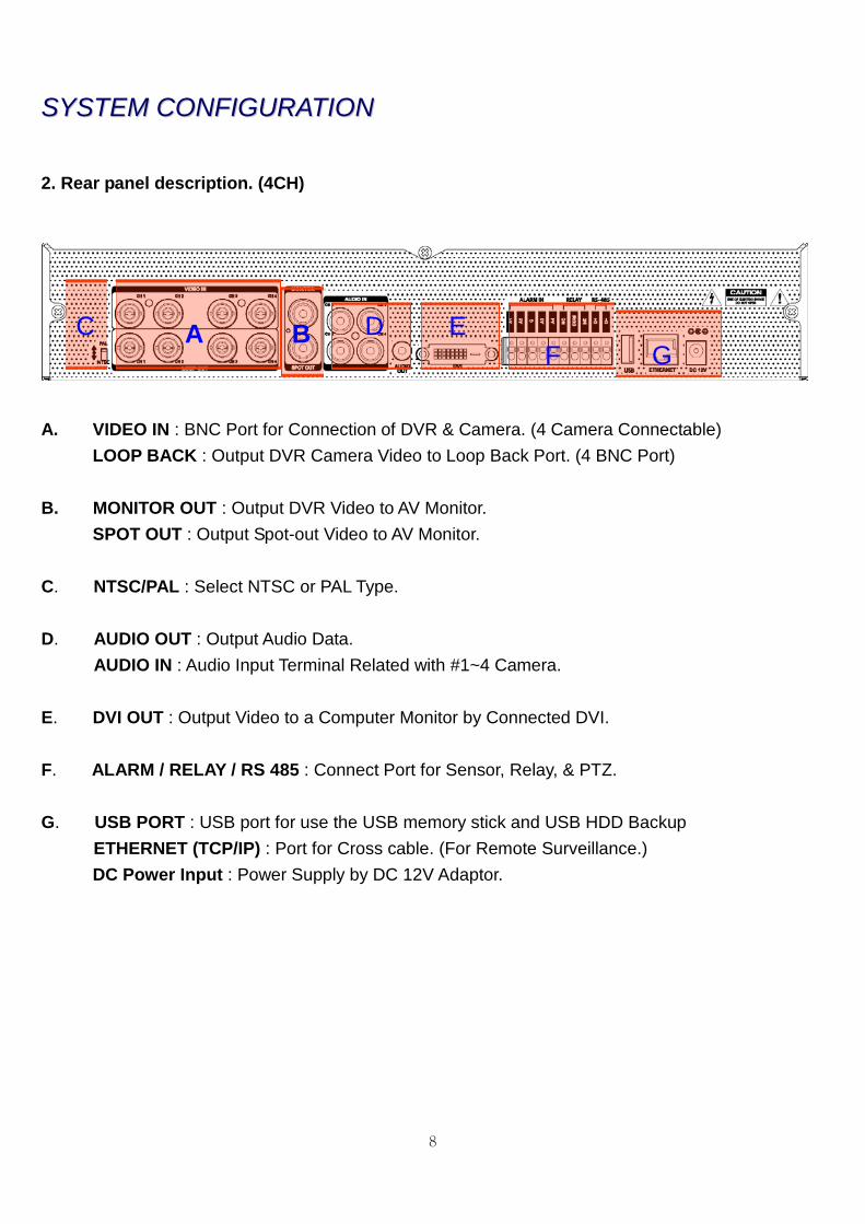
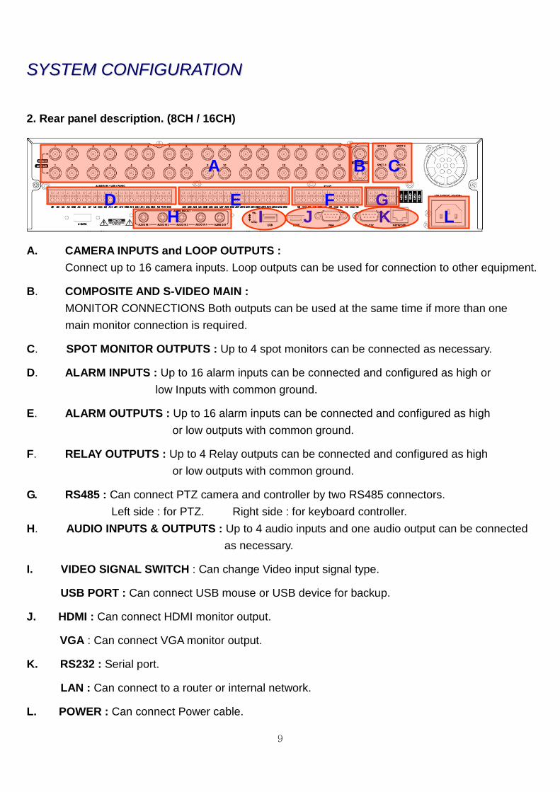
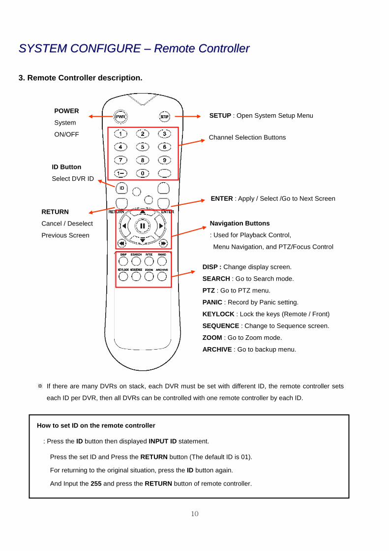
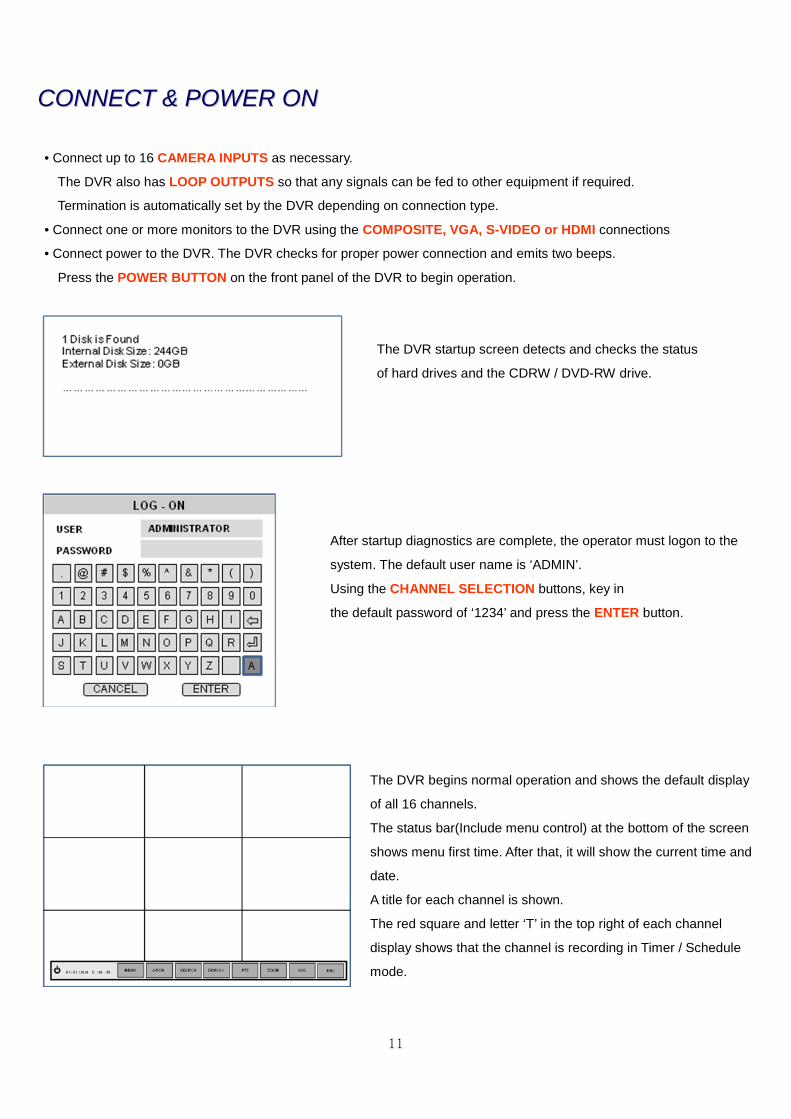
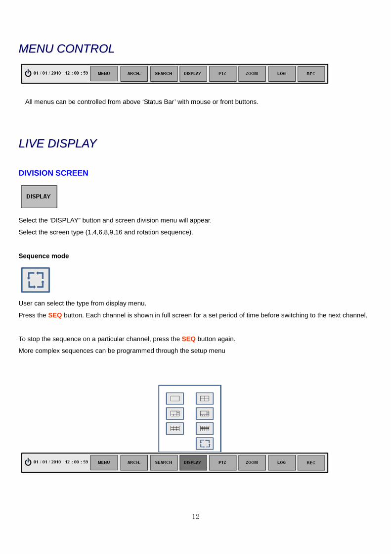
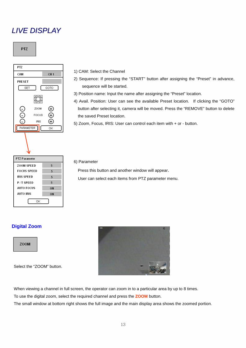
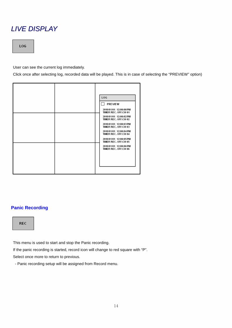
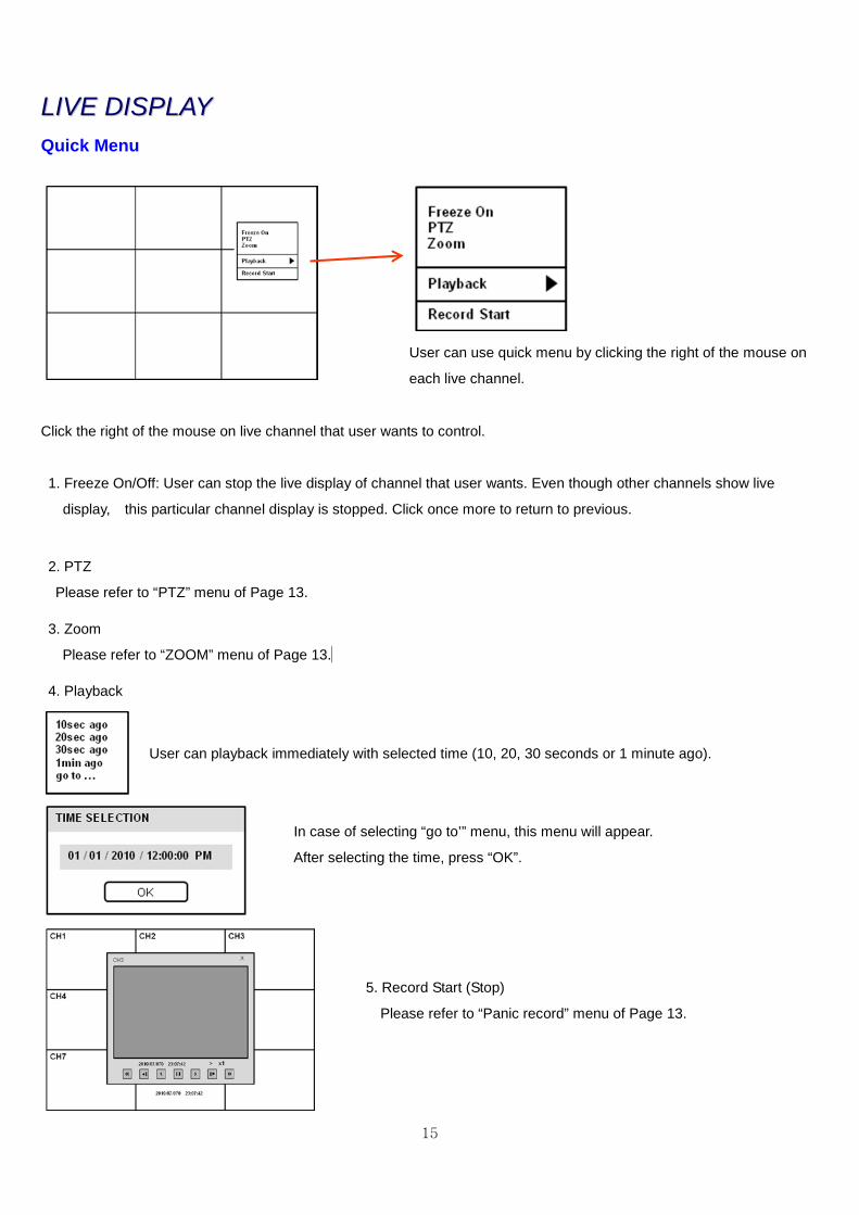
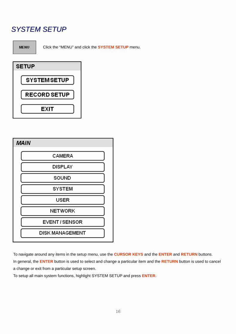
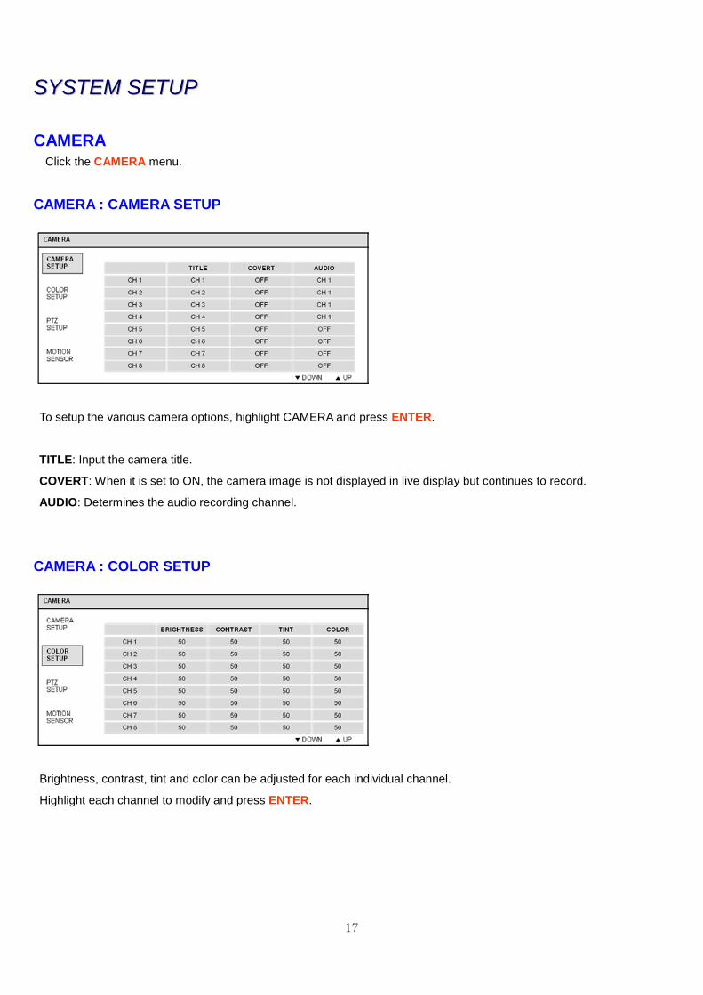
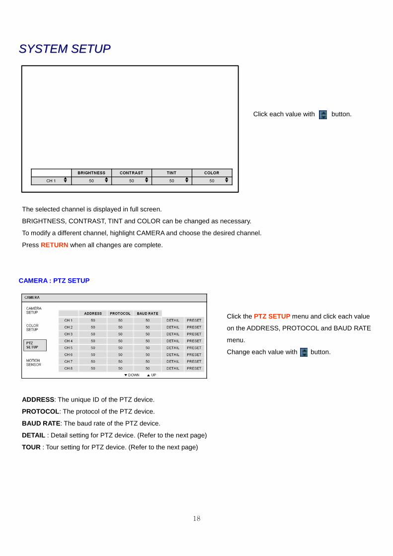
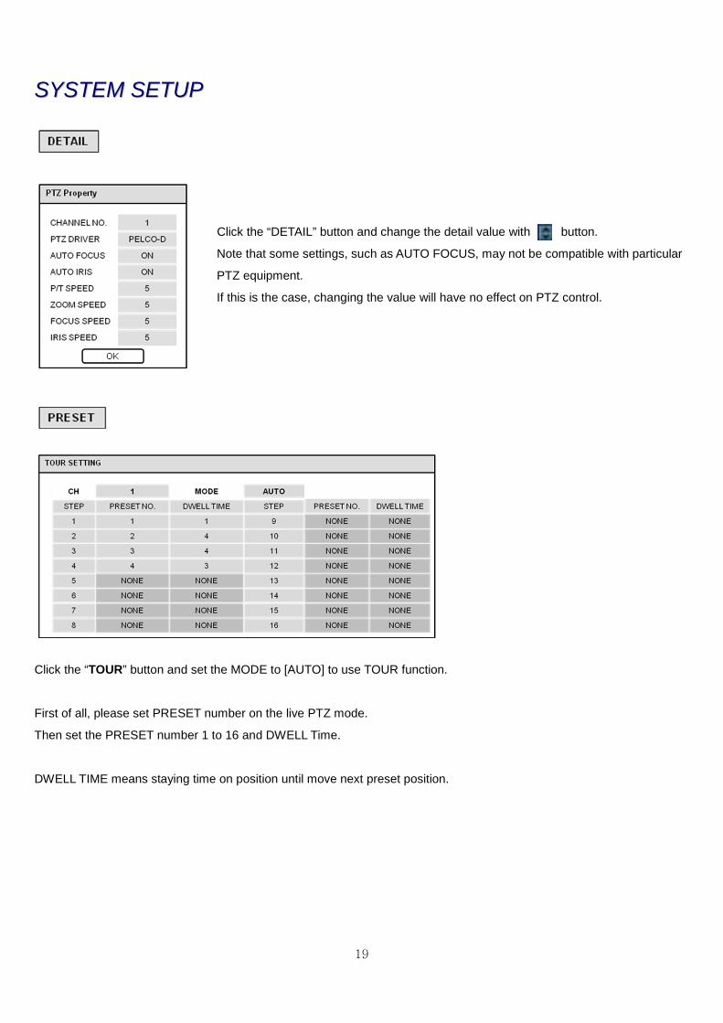
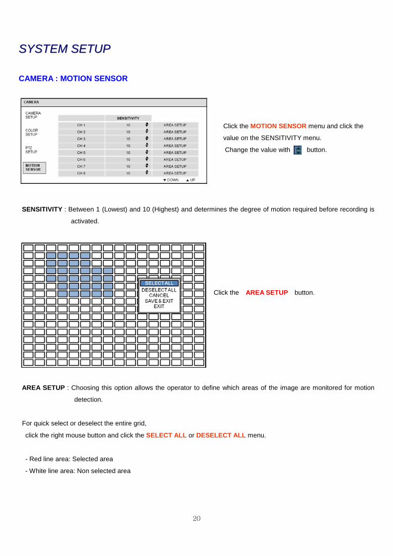
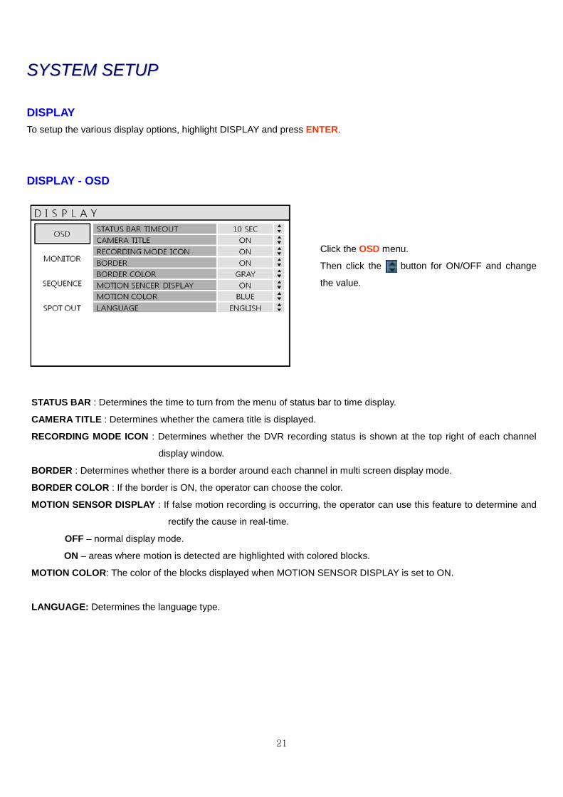
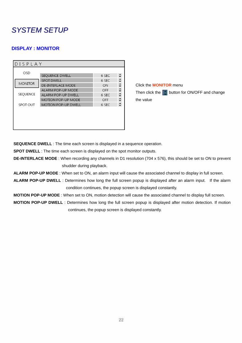
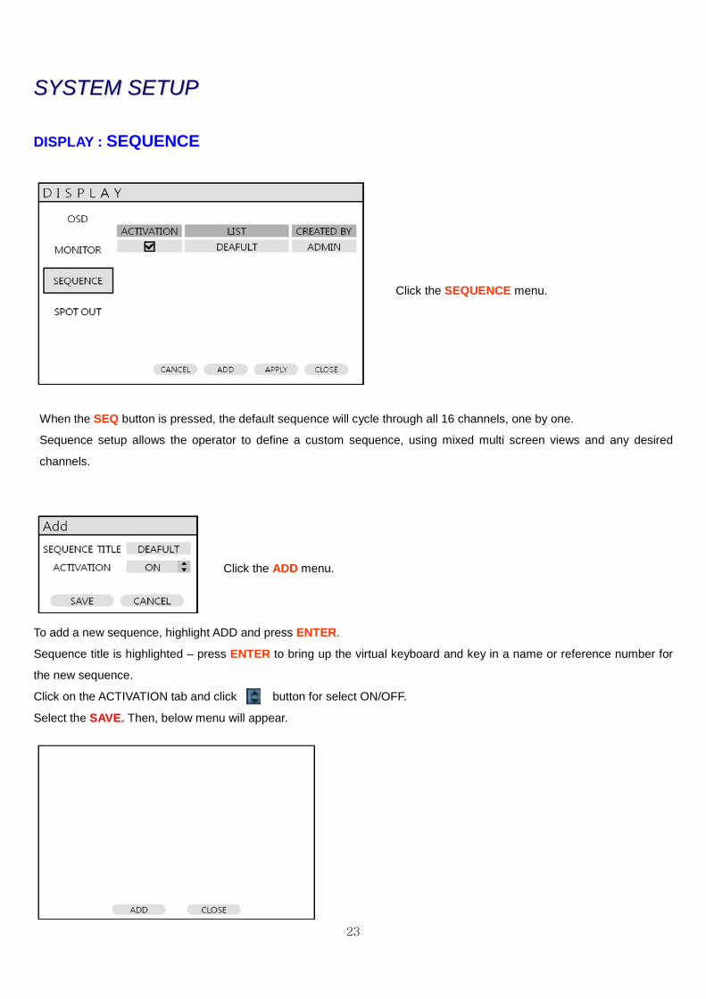
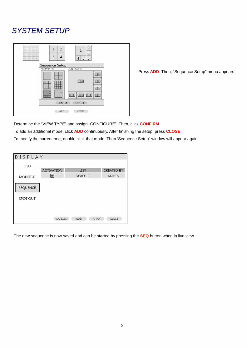
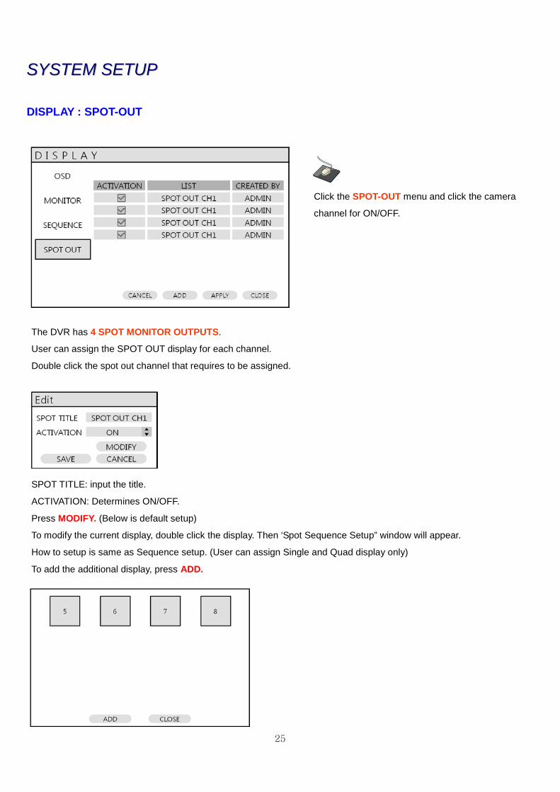
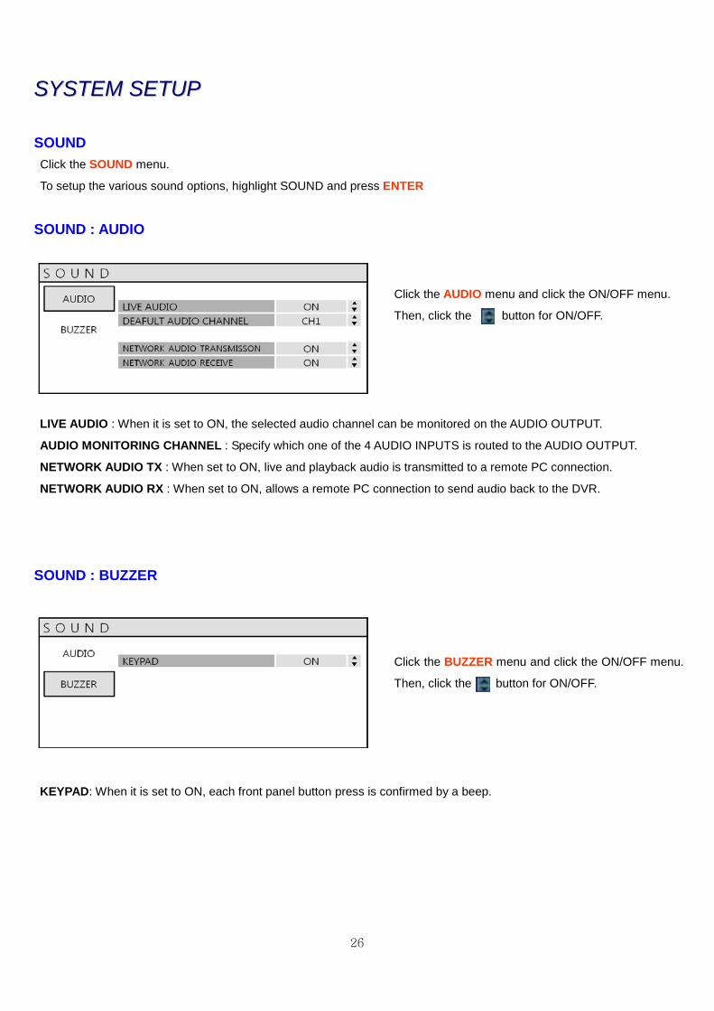
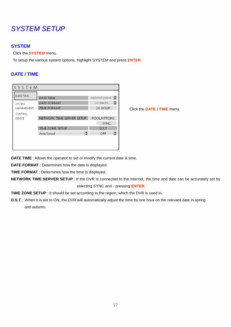
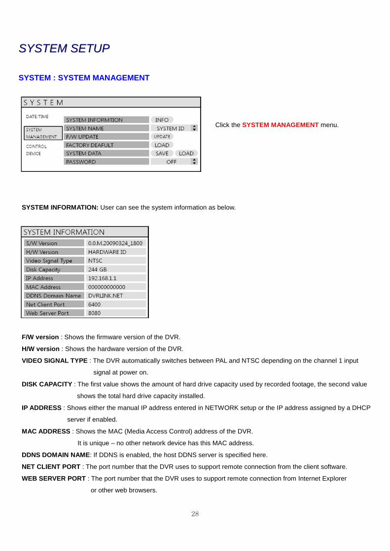
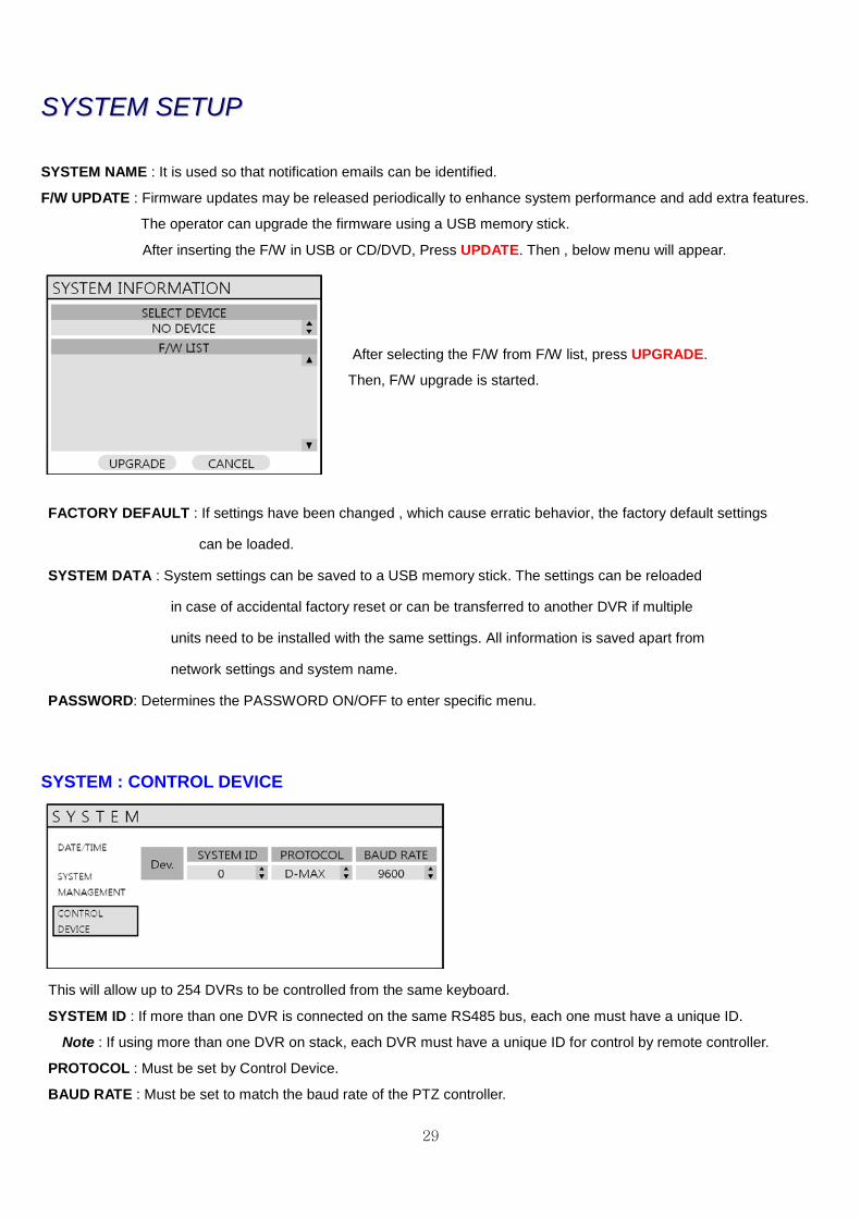
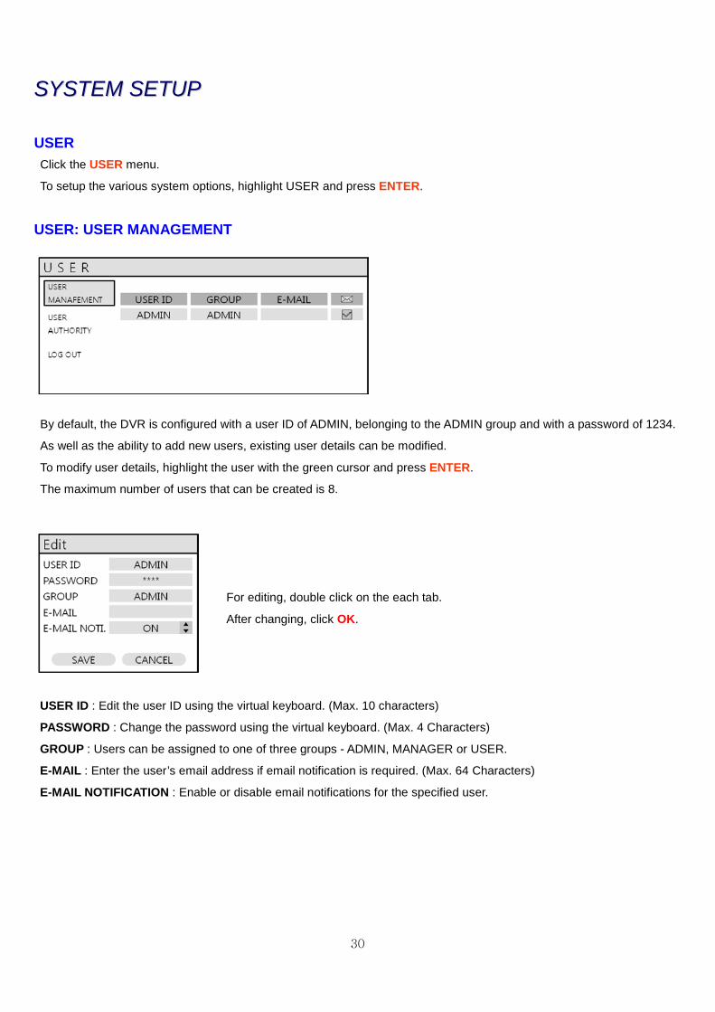
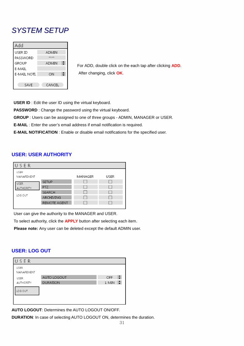
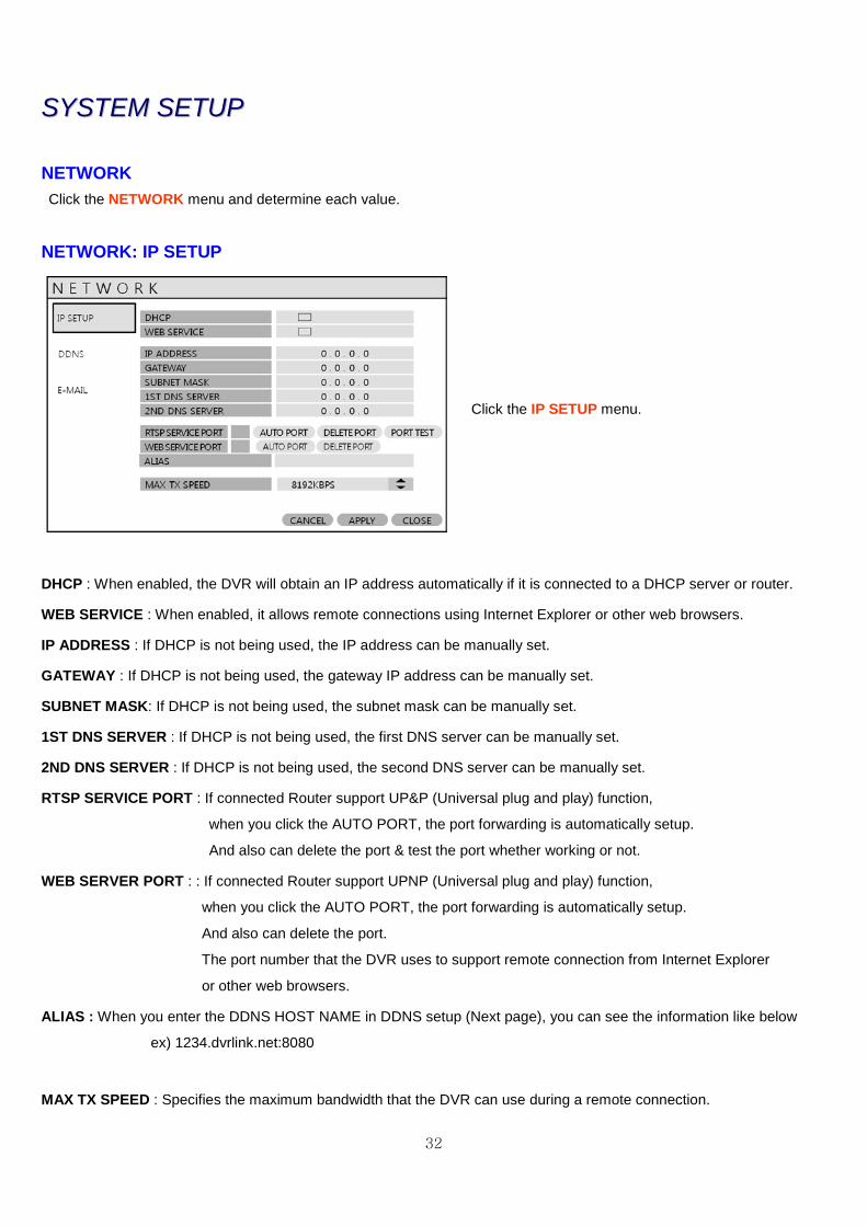
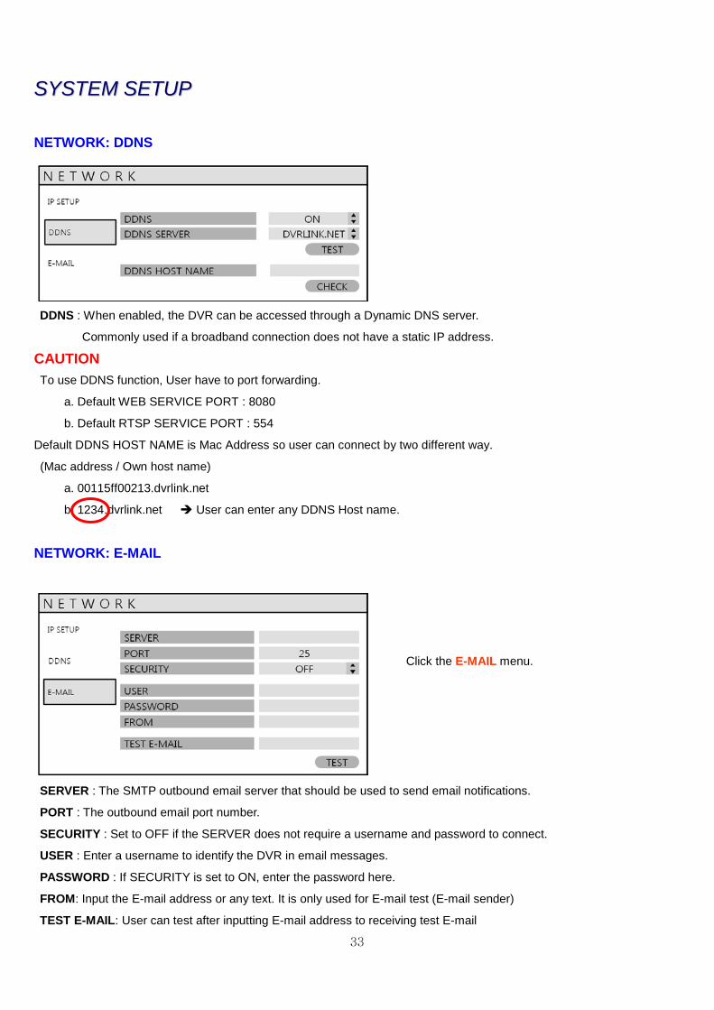
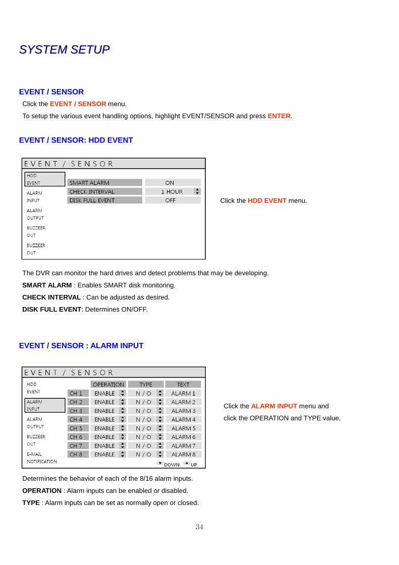
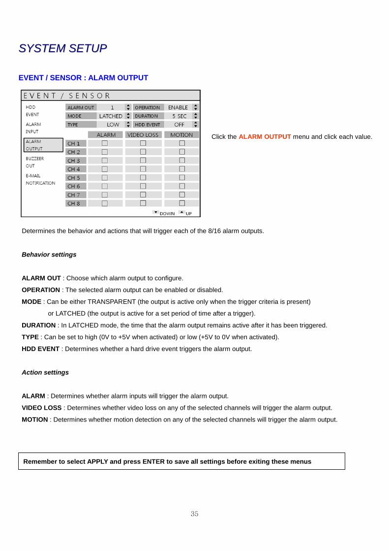
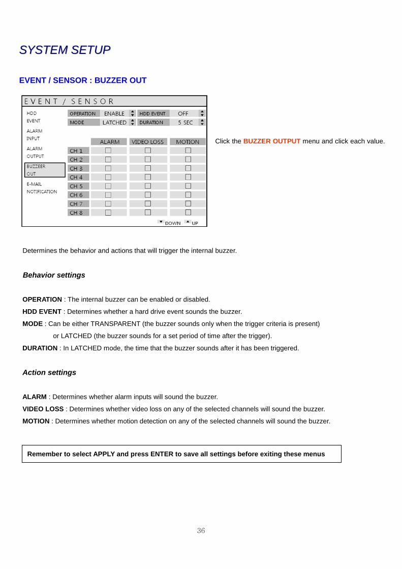
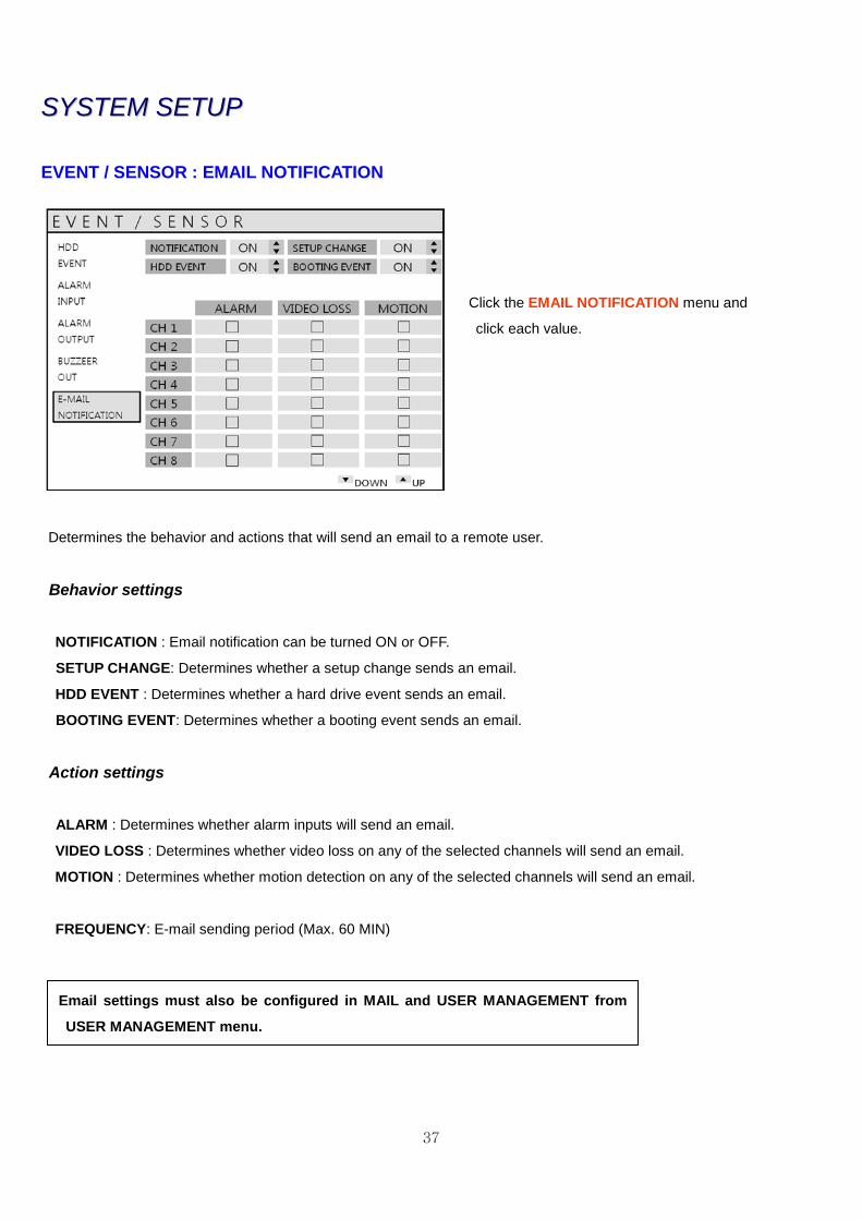
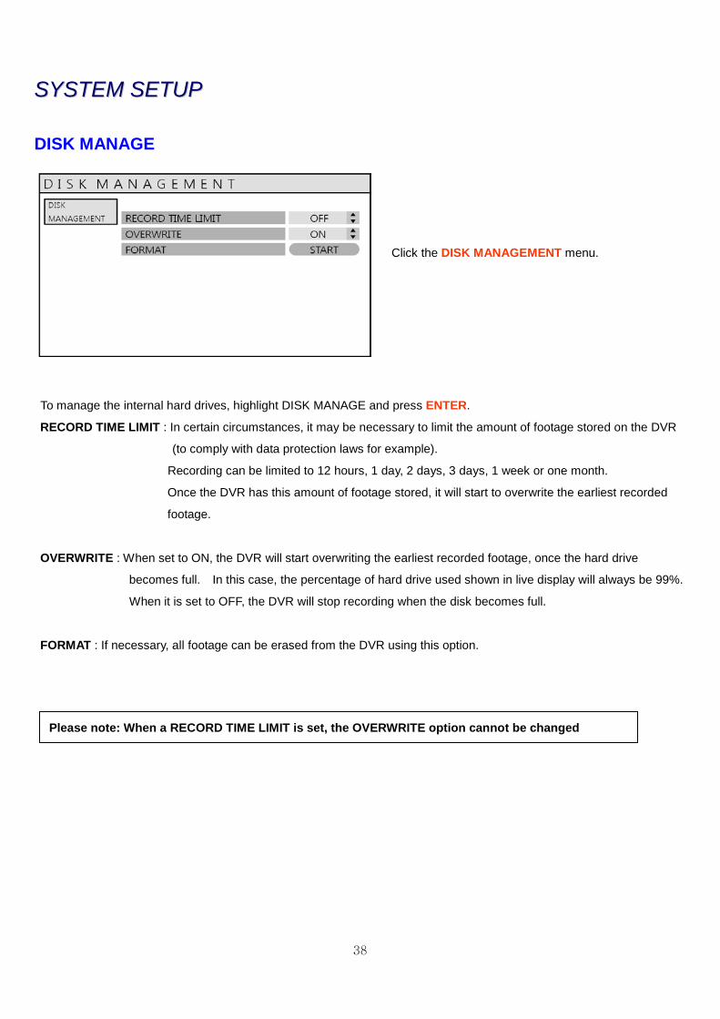
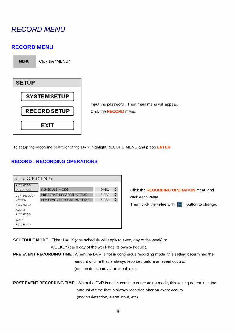
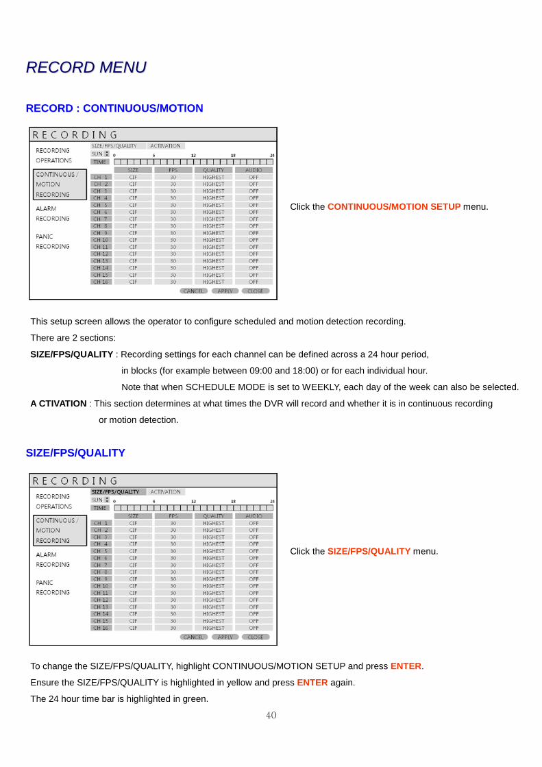
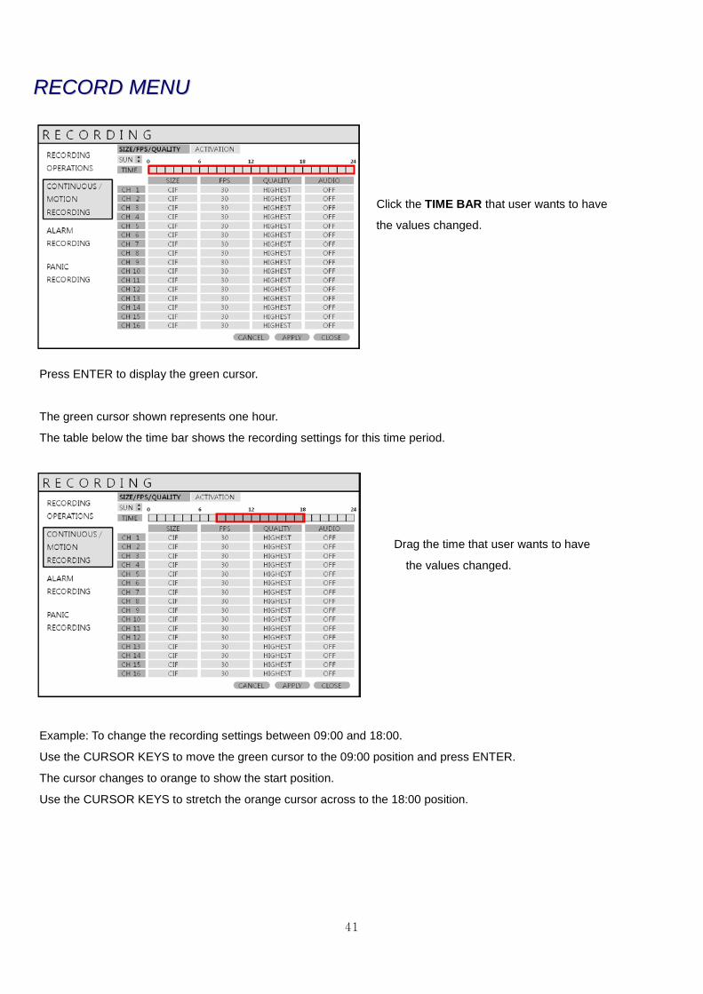
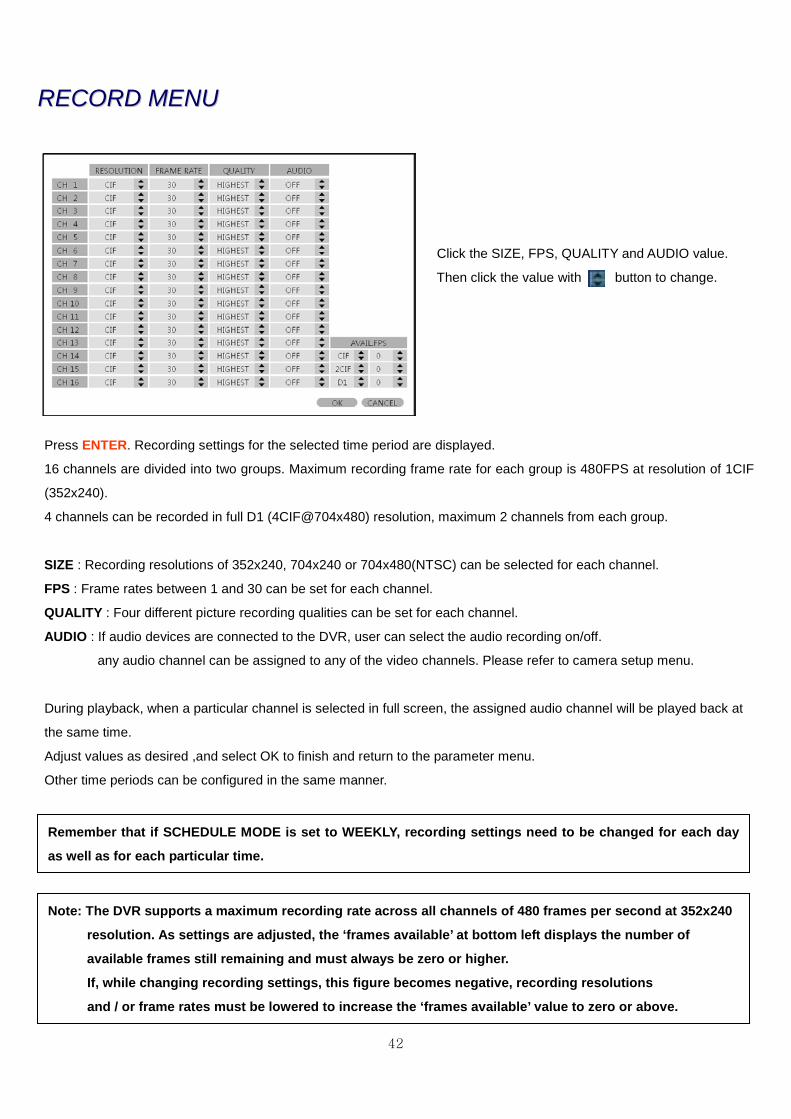
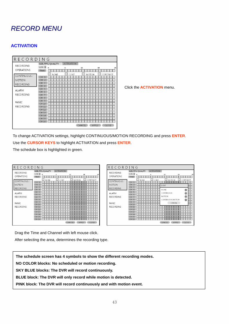
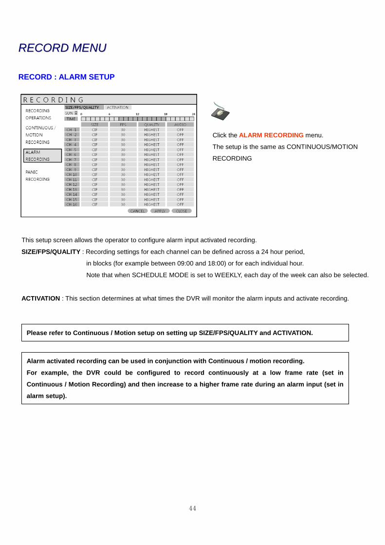
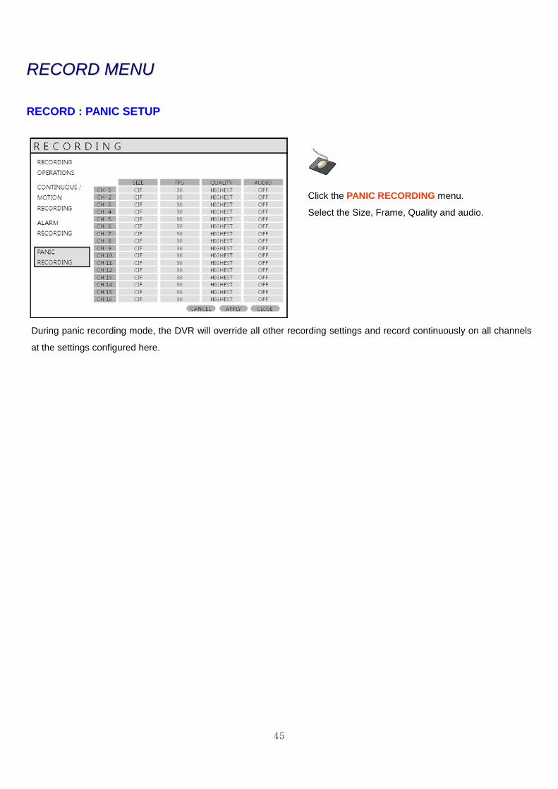
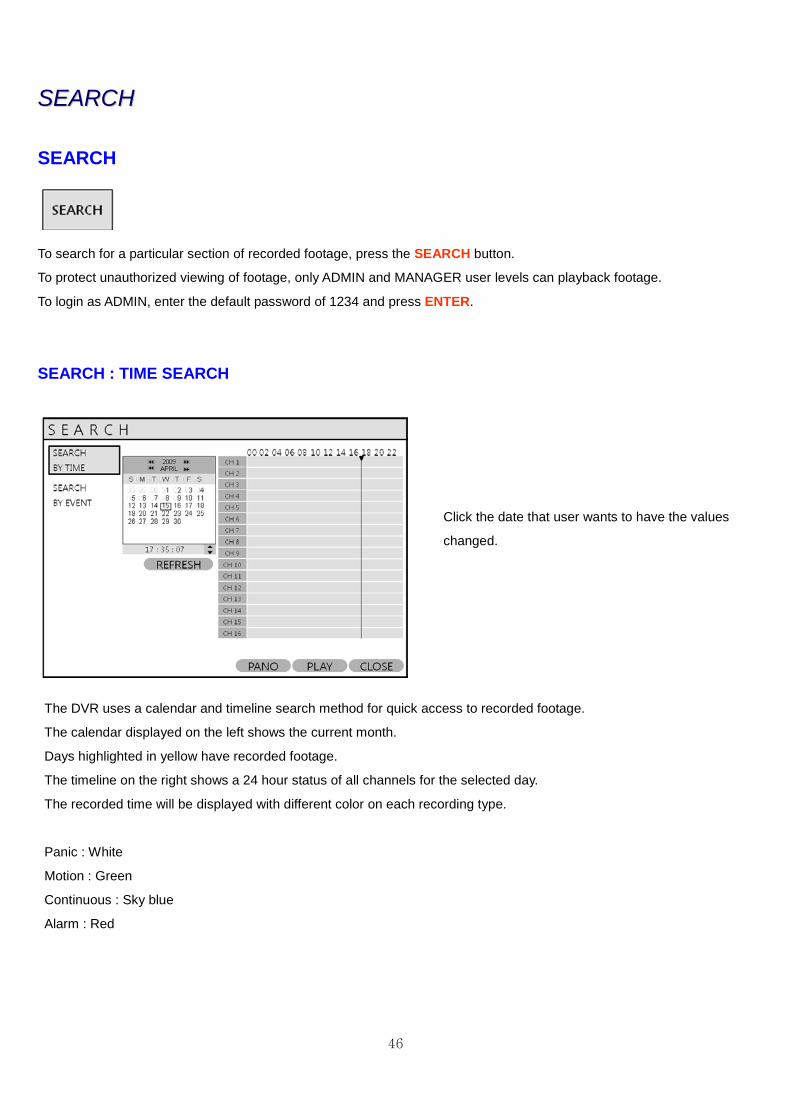
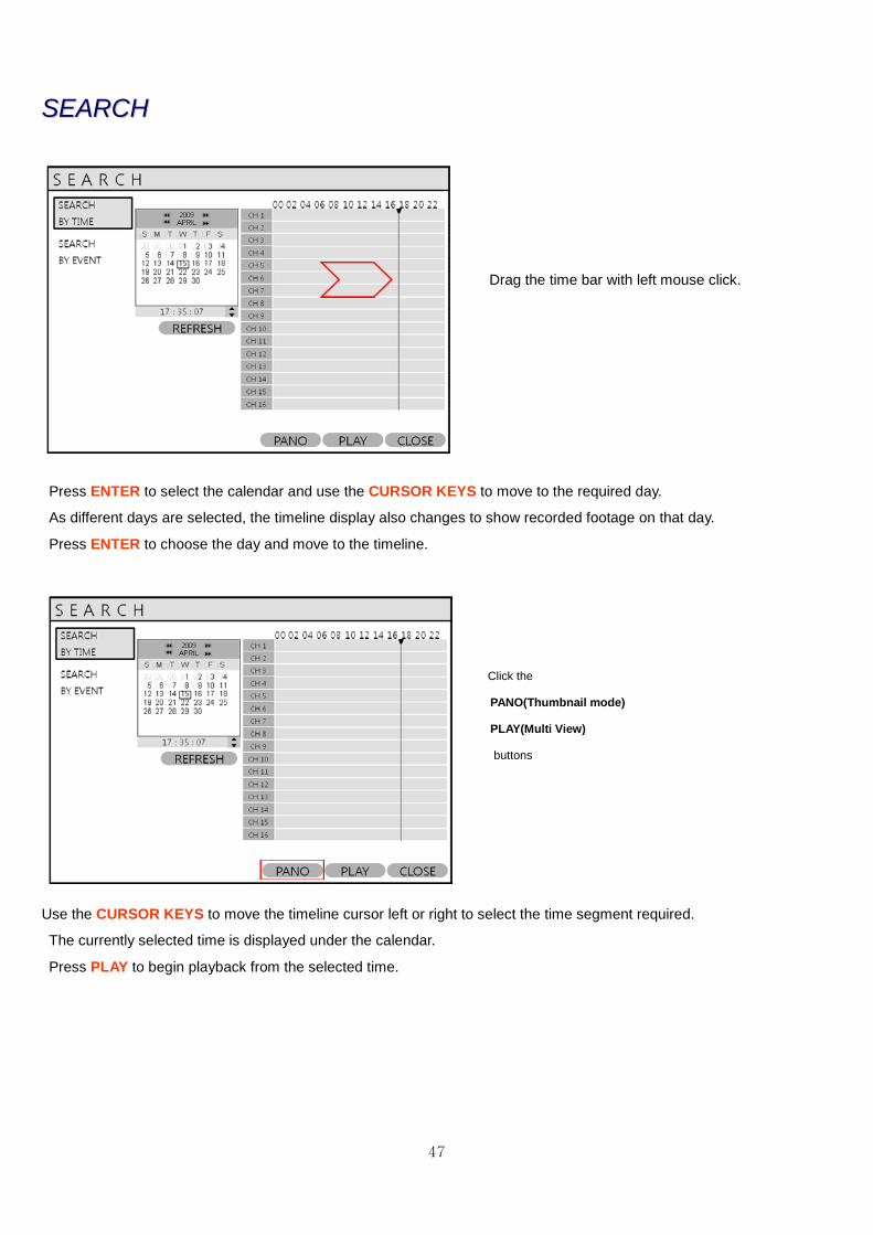
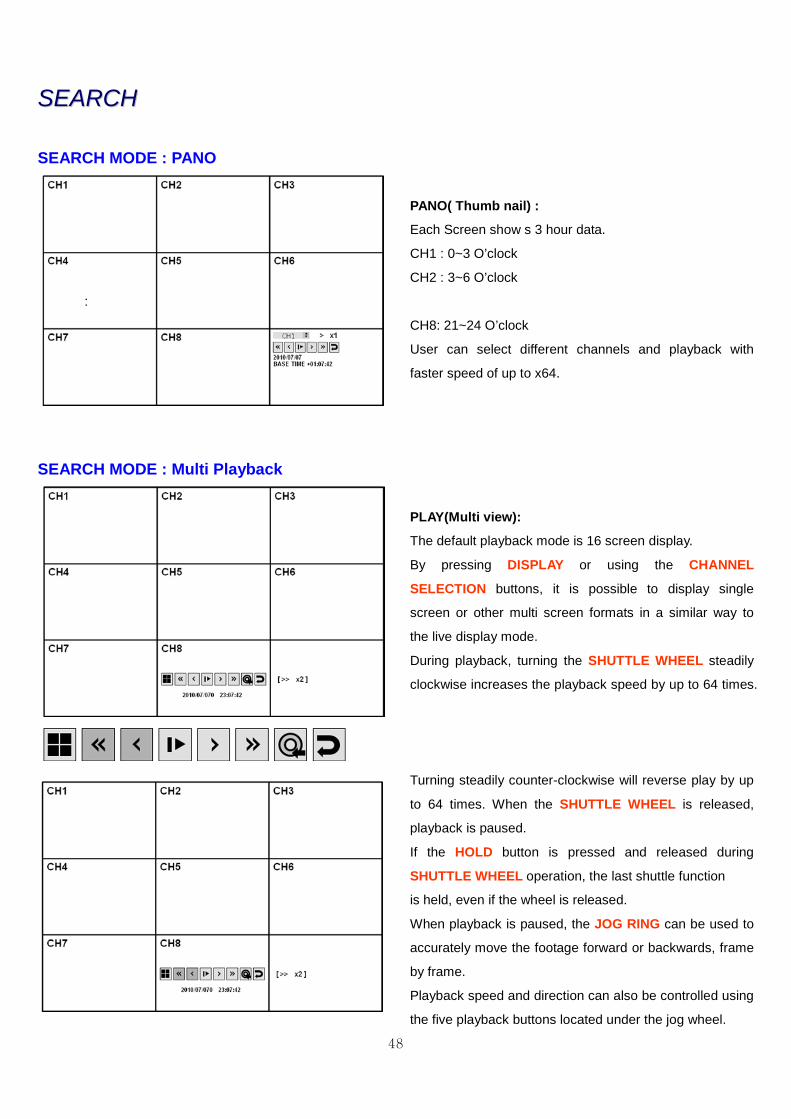
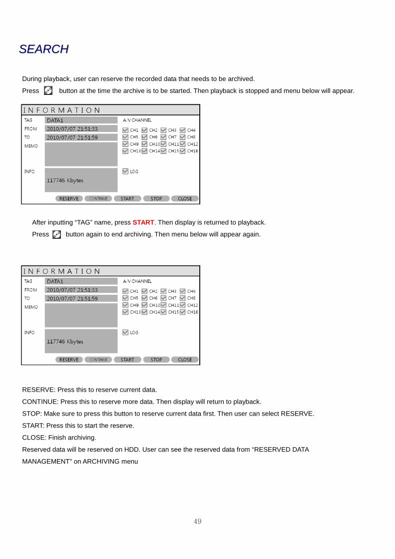
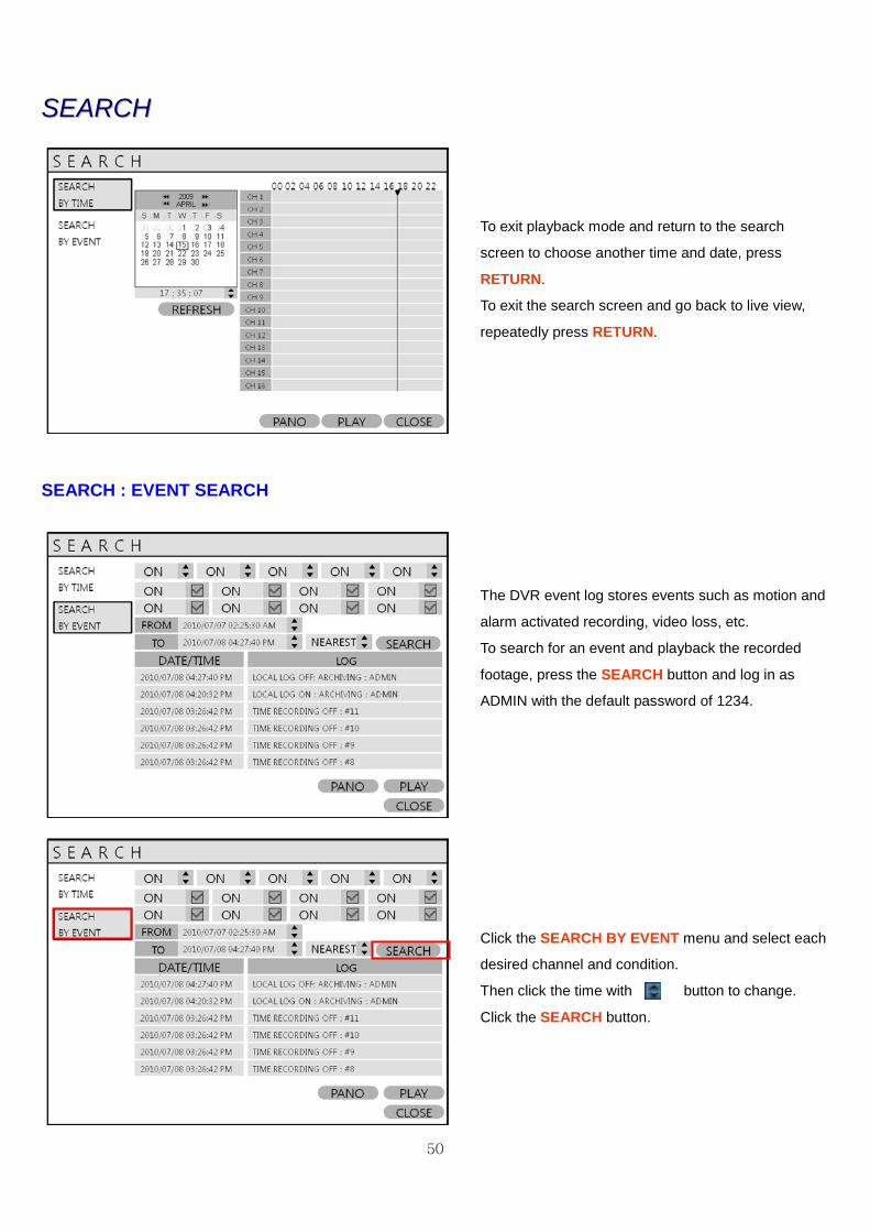
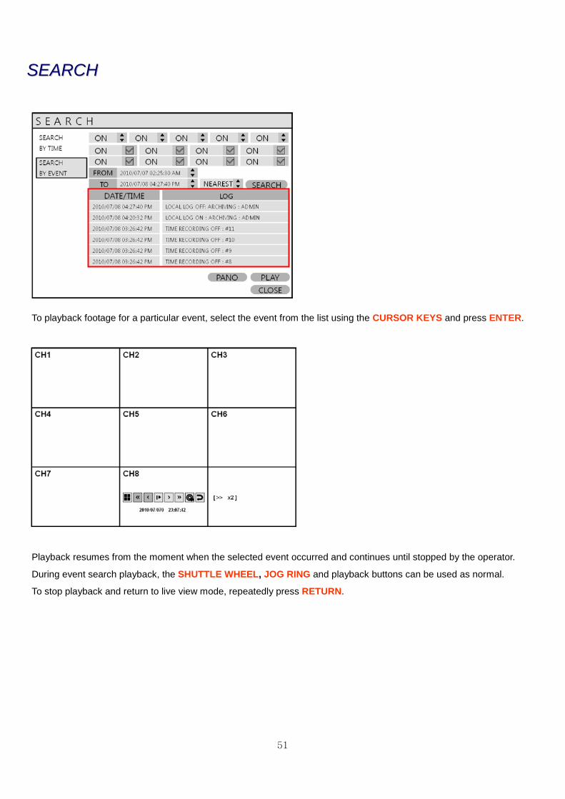
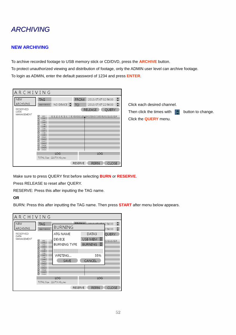
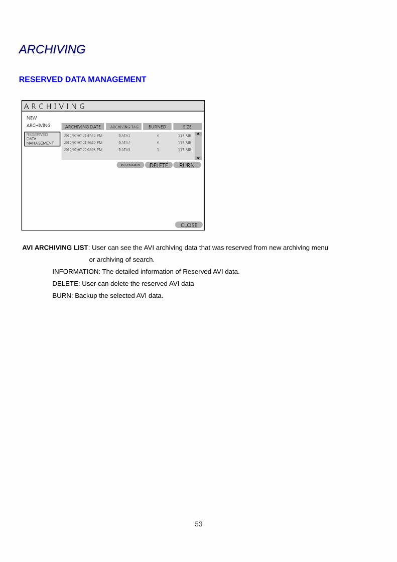
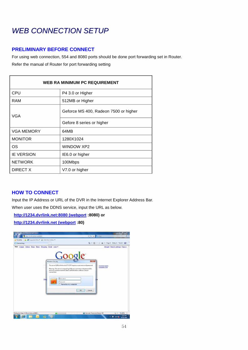
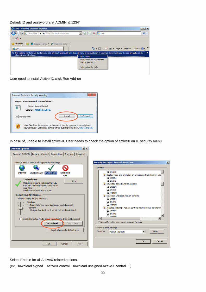
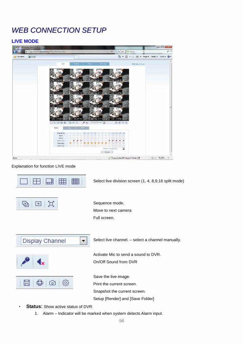
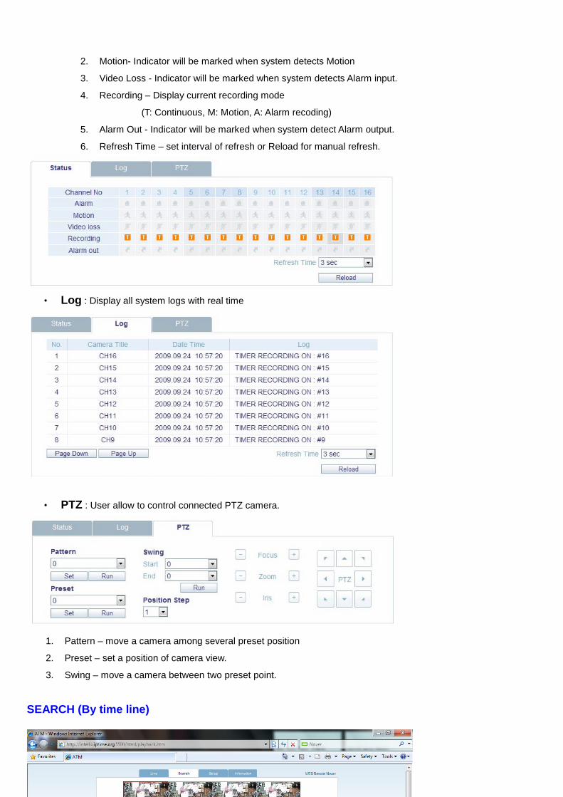
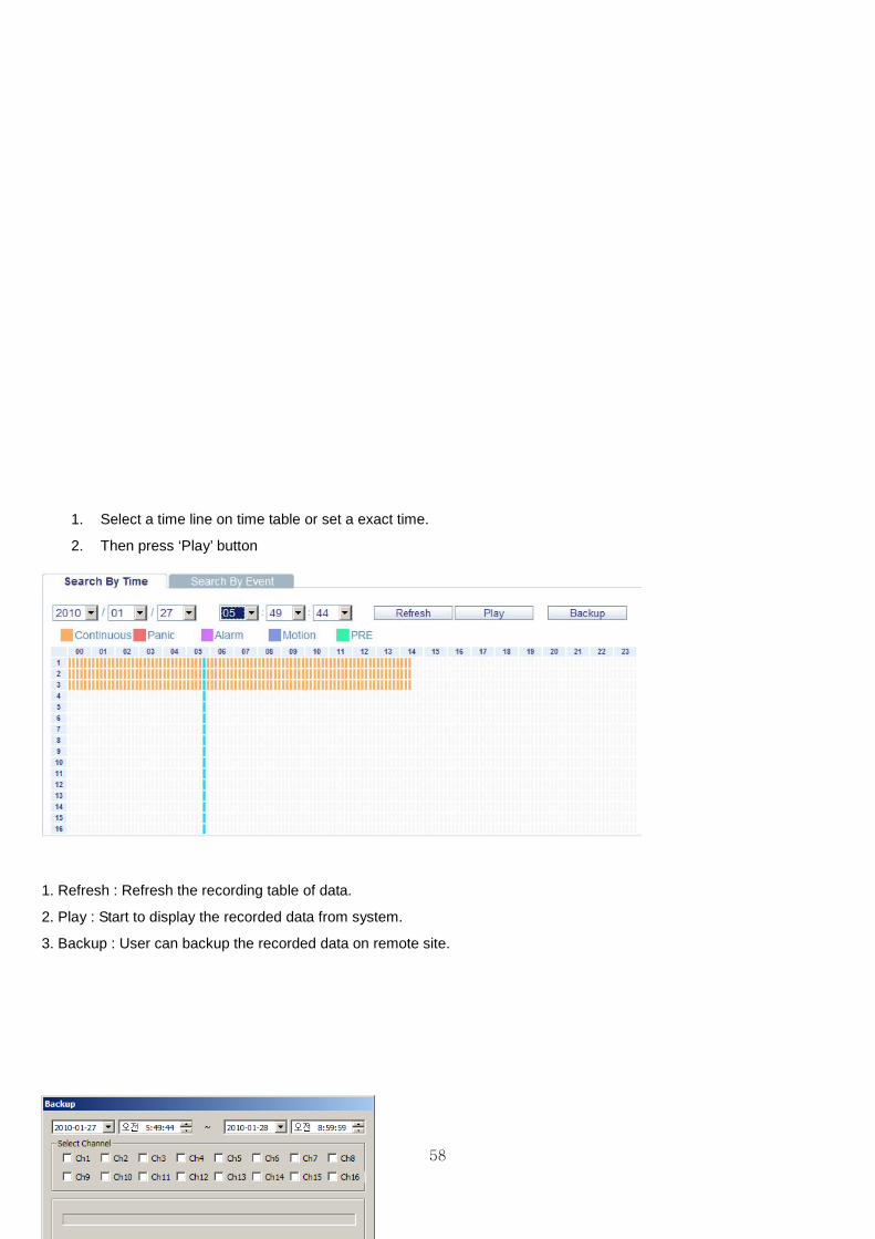
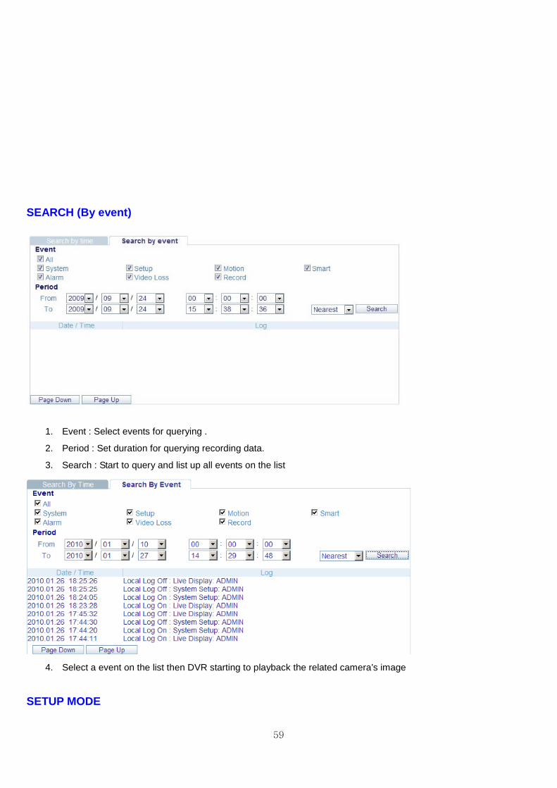
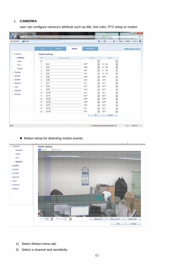
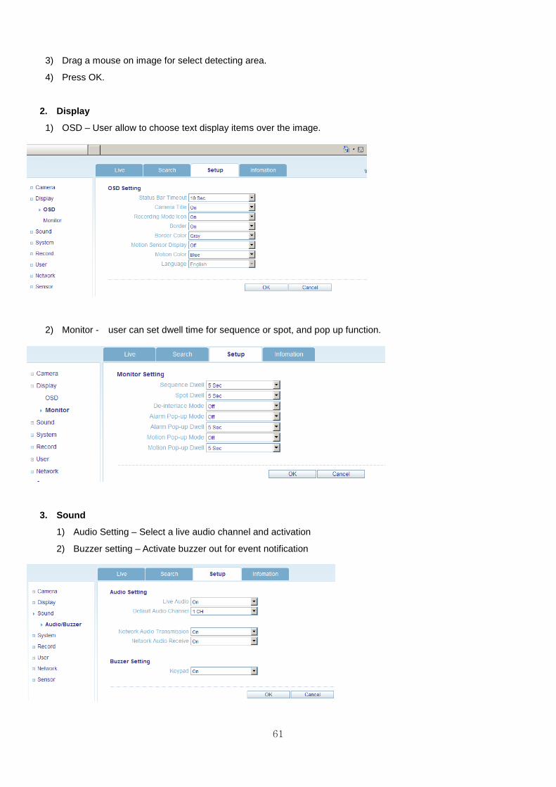
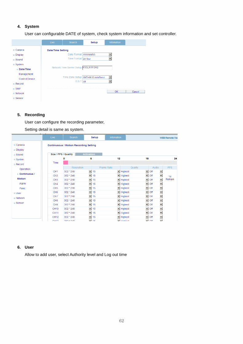
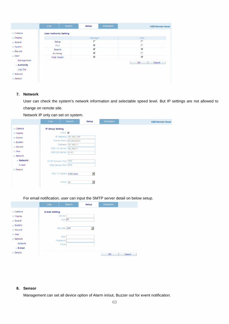
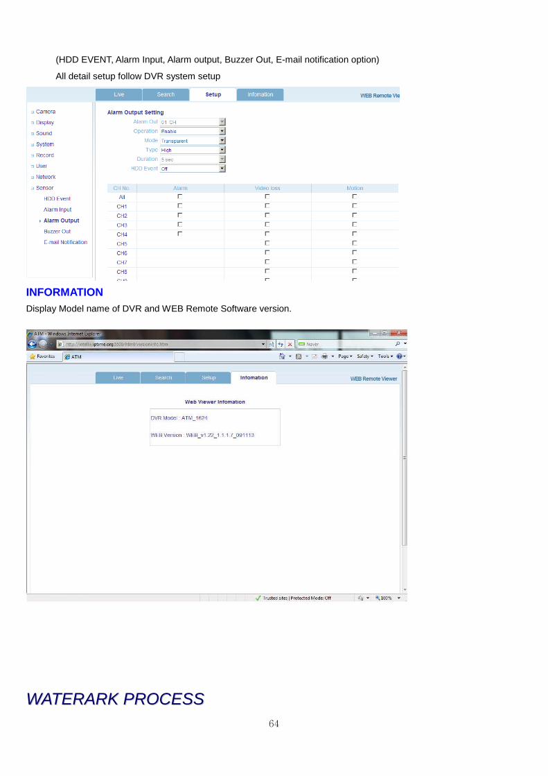
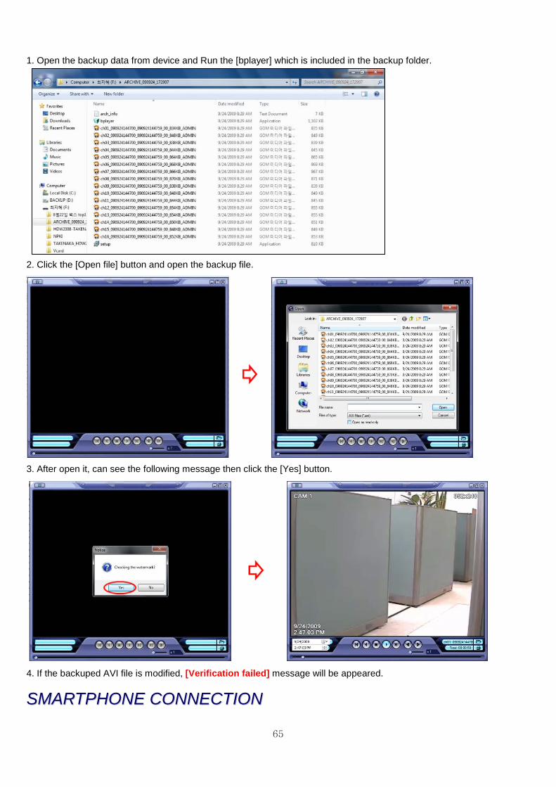
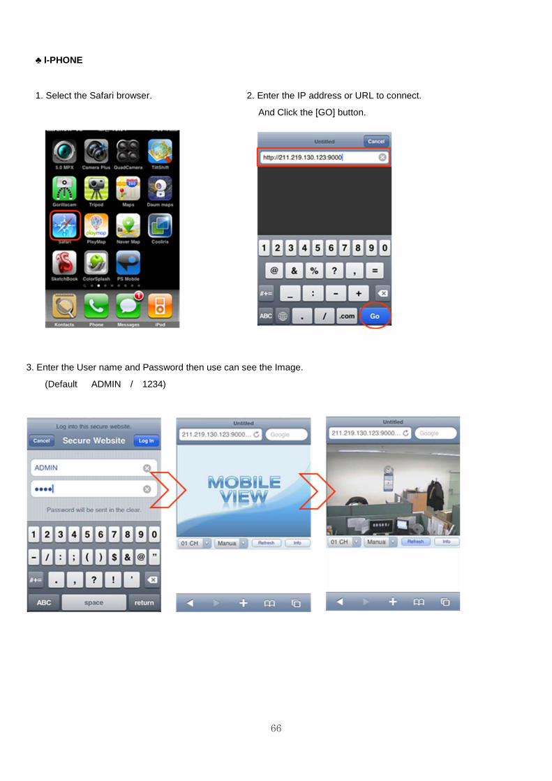
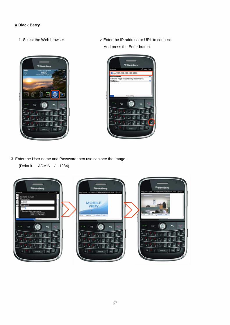
67
clubs Black Berry
1 Select the Web browser 2 Enter the IP address or URL to connect
And press the Enter button
3 Enter the User name and Password then use can see the Image
(Default ADMIN 1234)