Embed Size (px)
Citation preview
Hints and Tipsfor installing HF electronic lighting in a professional way


Hints and Tips 1
1. Introduction. 2
1.1. The built-in quality of Philips lighting components 2
1.2. This guide 2
2. Hints for the construction of luminaires with HF control gear. 3
2.1. Earthing 3
2.2. Ignition aid 3
2.2.1. What is an ignition aid? 3
2.2.2. When and how to use an ignition aid 3
2.2.3. What to do if the use of an ignition aid is not possible? 3
2.3. Voltage rating of components and wiring 3
2.4. Hints for wiring 3
2.4.1. Introduction 3
2.4.2. Control wiring (regulating ballasts) 4
2.4.3. Special wiring 4
2.4.4. Changing from conventional to HF gear 4
2.4.5. Wiring for luminaires with three or four HF ballasts 4
2.4.6. Wiring diagrams 4
2.5. Ambient temperatures and lifetime of the ballasts 4
3. Hints for the installation of HF luminaires. 6
3.1. Master-slave applications 6
3.2. Earth leakage circuit breakers 6
3.3. Inrush currents 6
3.4. Testing the installation 7
3.5. Ambient luminaire temperatures and optimum ballast lifetime 7
3.6. Trouble shooting 8
4. The lighting installation and environment. 11
4.1. Electromagnetic compatibility 11
4.1.1. RFI (radio frequency interference) 11
4.1.2. Immunity 11
4.2. Humidity 11
4.3. Interference with infra red remote control equipment 11
4.4. Interference with translation / congress systems 11
4.5. Norms, standards and approvals 12
5. Other basic aspects. 13
5.1. Emergency lighting 13
5.2. HF Ballasts and dimming 13
6. Colour coding of the HF Matchbox ballasts. 14
7. Warranty. 15
7.1. 3 year warranty 15
7.2. 5 year warranty 15
8. More information or support needed?. 16
Contents

Hints and Tips2
On account of their great advantages compared to
conventional gear, high-frequency (HF) electronic ballasts
have gained great popularity in many applications over
the last decades. The use of electronics provides more
comfort and fl exibility, whilst the light can be easily
regulated to one’s own requirements. Another highly
relevant benefi t of HF lighting is the fact that considerable
cost reductions can be obtained thanks to energy-saving
qualities of HF electronics. Besides, the compact electronic
components of these days allow for a new innovative
design of luminaires. A typical example of this is the TL5
system. This booklet is related to the European products
of Philips Lighting (HF-Regulator, HF-Performer, HF-Basic,
e-Kyoto and HF-Matchbox).
1.1. The built-in quality of Philips lighting
components
In many laboratories all over the world, lighting
engineers are working hard on constant improvement
of Philips products, including ballasts, for the provision
of reliable and fi rst-rate lighting installations. Obviously,
great emphasis is thereby laid on quality in terms of
performance, lifetime and similar aspects.
Philips HF electronic ballasts are manufactured in ISO
9001-certifi ed factories. All ballasts fulfi l the relevant
international norms, ensuring optimum performance and
the new lighting installation.
But in the Philips vision that is not enough. Also easy
installation and operation are critically taken into account
during the product creation process. And the opinion of
the end-user highly valued in this process.
On top of that, Philips also takes full responsibility for the
care of the environment and is therefore ISO 14001-
certifi ed. This implies that the use of Philips HF electronic
ballasts ensures the fulfi lment of the environmental
management system, as certifi ed by the offi cial approval of
the Dutch test authority KEMA.
1.2. This guide
In this guide useful hints and tips can be found on how
to apply HF electronic ballasts in a lighting installation.
Subjects that will be dealt with include: the proper
construction of luminaires designed to be equipped with
HF control gear, as well as how to install and operate such
luminaires. Also aspects like testing, trouble-shooting and
maintenance will be covered.
The interaction between HF lighting installations and the
environment will receive special attention too.
Finally, a few words will be spent on dimming and
emergency lighting, and the guide concludes with a list of
literature for further reading.
And remember:
Obtaining an outstanding lighting installation
is not simply a matter of choosing the best
possible components: their proper installation and
operation in the system is equally important.
1. Introduction

Hints and Tips 3
2.1. Earthing
Unless specially mentioned, it is assumed that the HF
ballasts are mounted in a Class I luminaire (provided with
a ground point), and that they are electrically very well
connected to some metal part of the luminaire.
For ballasts housed in a metal case this is normally
obtained by means of the fi xing screws with which the
ballasts is mounted to the earthed mounting plate. Tooth-
lock washers should be used to ensure a proper earth
contract right through the paint or lacquer covering the
luminaire. Fixing screws for mounting the ballast should
be 4 mm diameter. Ballasts in a plastic housing must be
earthed via the connector if available.
2.2. Ignition aid
Generally speaking, fl uorescent lamps at all temperatures
require an ignition aid for proper ignition. This is stated
in IEC 60081-Annex A. If a certain type of lamp does not
need an ignition aid, this must be specifi cally mentioned
in the relevant lamp documentation provided by the lamp
manufacturer, for example, PL-T lamps.
2.2.1. What is an ignition aid?
An ignition aid, sometimes also called ‘starting aid’, is a
metal plate with a length extending at least over the lamp
length and a width of at least 1.5 times the lamp diameter.
It should be connected to earth (or to an earth contact
on the ballast). Its purpose is to make lamp ignition easier.
Typically, the distance between the ignition aid and the
surface of the lamp should be:
- 13 mm for TL-D lamps
- 6 mm for TL5 lamps
- 12 mm for PL-L lamps
Note:
Under no circumstance should there be any conducting
(metal) plate between the ignition aid and the lamp, unless it
is electrically connected to the earth point of the luminaire (or
an earth contact on the ballast). This also applies, for instance,
for an aluminium refl ector or a refl ector made of synthetic
material that is sprayed with lacquer that contains metal
particles. The ignition aid must always directly face the lamp.
Ignoring this can result in not igniting lamps.
2.2.2. When and how to use an ignition aid
- For Class I (i.e. mains earthed) metal luminaires a
separate ignition aid will in general not be required, as
the luminaire itself will fulfi l this function.
- For Class I plastic luminaires, a separate ignition aid has
to be mounted and connected to the earth contact of
the ballast.
- In the case of a Class II luminaire (no provision for
protective ground), the ignition aid must be connected
to the earth connection of the ballast.
2.2.3. What to do if the use of an ignition aid is not
possible?
The proper ignition of the lamp(s) will depend on
the type of ballast, the position of the ballast and
the wiring between the ballast and the lamp(s).
For this reason, luminaires without ignition
aid can only be released after testing. If help is
required, please contact your local Philips sales
representative.
2.3. Voltage rating of components and wiring
In general, 250V-rated electrical components and
300V-rated wiring (as H05 classifi cation) can be used
in luminaires. Exceptions to this rule are the dimming
systems for PL-T and TL5. Here, 500 V-rated lamp holders
and 450V-rated lamp wiring (like H07) have to be used, on
account of the high lamp voltages (up to 430 Vrms) when
dimming the lamp(s).
Normal ‘H07’ wiring has a minimum conductor cross-
section of 1.0 mm2.
Most ballasts are suitable for such a conductor thickness,
and most TL5/PL-T lamp holders can cope with a
maximum wire cross-section of 1.0 mm2.
Note: High lamp voltages may arise when fl uorescent
lamps are dimmed. If this happens, it always has to do with
the chosen lamp concept and is not dependent on ballast
technology.
2.4. Hints for wiring
2.4.1. Introduction
It is important to pay attention to the following indications
2. Hints for the construction of luminaires with HF control gear

Hints and Tips4
in order to get optimum system performance and
minimum radio frequency interference:
- Keep mains (and control) wiring away from lamp wiring
and lamps (minimum distance 2 cm) (see Figure 1).
- If complete separation is not possible, screen the mains
(and control) wiring by an earthed metal sheath or plate.
- Keep mains (and control) wires as short as possible.
- As a general rule, the length of the wires should be
in accordance with the advised fi gure for the relevant
ballast type.
- Avoid loops in all wiring.
- Take care of fi rm electrical contact between all metal
parts and the ballast housing.
Figure 1
2.4.2. Control wiring (regulating ballasts)
In the case of control wiring, the following points should
be regarded:
- The wiring to the control input must be dealt like mains
wiring.
- If 1-10V ballasts are used, take care that the polarity of
the dimming connection is correct.
2.4.3. Special wiring
In the case of throughput wiring:
- Take extra care that throughput wiring in a luminaire
is completely separated from the lamp wiring in order
to avoid deterioration of the EMC behaviour of the
luminaire.
2.4.4. Changing from conventional to HF gear
HF electronic ballasts consist of one single unit, replacing
various components in conventional electromagnetic
systems, such as a radio-interference capacitor, a starter
and the electromagnetic ballast. When changing from a
conventional ballast system to an electronic one, but also
when swapping from one electronic ballast to another, it is
advised to check:
1. The quality of wires and lamp holders (ageing). If these
components are not in optimum condition, replace
all existing wiring before installing a new electronic
ballast. Also all redundant components of the previous
(electromagnetic) system should be removed.
2. Follow the hints as given in section 2.4.1: General wiring.
2.4.5. Wiring for luminaires with three or four HF ballasts
When three or four HF ballasts are used in a Class I
luminaire, the maximum earth leakage current may surpass
the maximum allowed 1.0 mA (according IEC 60598).
Reverse-connecting the mains and neutral on one or two
of the ballasts in the luminaire might cause the maximum
earth leakage current to fall below the required 1.0 mA.
This depends on the type of ballast that is used. HENCE:
this trick is not guaranteed to work with all types of
ballasts. This is because some ballasts do not have an L and
N marking and have internally a somewhat different setup.
2.4.6. Wiring diagrams
All wiring diagrams can be found in the related product
leafl et per type of ballast. Also on each ballast a wiring
diagram is printed in order to make it easy to install the
ballast without the need of a product data sheet.
On each ballast it is also printed:
1. What wiring diameters can be used
2. What the optimum strip length of the wires is
3. Which wires are to be kept as short as possible
2.5. Ambient temperatures and lifetime of the
ballasts
The maximum temperature in a luminaire is important
for the lifetime and reliability of electronic ballasts. The
only correct way of measuring Tambient for the ballasts
in the luminaire, is to measure Tcase at the test point
on the ballasts. The measurements can be done with
temperature-indicating devices or with a thermocouple.
For almost all HF electronic ballasts, the maximum
Tcase temperature is 75 °C.
The nominal lifetime of the ballasts is 50,000 hours at a
Tcase temperature of 75 °C (10 % failures). Every increase

Hints and Tips 5
of the Tcase by 10 °C will halve the lifetime of the ballast.
Example:
Tcase = 65 °C, lifetime approx. 100,000 hours,
Tcase = 85 °C, lifetime approx. 25,000 hours.
Exceeding the maximum Tcase temperature with more
than 10 °C, this will result in an undefi ned reduction of
the ballast’s lifetime.
Below Tcase = 65 °C the lifetime of the ballasts will
improve, but not by a factor 2 per 10 °C.
Some types of ballasts (HF-Matchbox Blue and e-Kyoto)
have a slightly different lifetime expectation. For the HF-
Matchbox Blue and e-Kyoto the data are 80,000 hours and
20,000 hours.
Tips for ballasts temperature reduction:
1. Mount the ballast not too close to the lamp ends.
2. Take care of good heat transport to the surroundings,
called heatsinking.
3. Avoid heat radiation from lamp to ballast.
4. Create extra luminaire volume.
5. Have some airfl ow around the ballast.

Hints and Tips6
3.1. Master-slave applications
There are situations where two single-lamp luminaires in
a so-called master-slave confi guration will be operated
on one HF ballast designed to operate two lamps (see
Figure 2). Although in most cases this is not advised,
follow the indications below with regard to cable length
and maximum distances as shown in the accompanying
drawing. This is to avoid problems with regard to radio
frequency interference and ignition. The cable connecting
the master luminaire with the slave luminaire should not
be of the shielded type. Also the wiring for both lamps
should be of the same length.
HF and master-slave wiring length (see Figure 2)
Ballasts type D L
e-Kyoto < 1 m < 3 m
HF-B TL-D < 1 m < 3 m
HF-P TL-D < 1 m < 3 m
HF-P TL5 (not advised) < 0.1 m < 2 m
HF-R TL-D/TL5 (not advised) < 0.1 m < 2 m
Table 1
Figure 2
3.2. Earth leakage circuit breakers
The earth leakage current of HF electronic ballasts is
normally less than 0,5 mA. At the moment of switching-on
the installation, the earth leakage current may, however,
be temporarily higher. For this reason it is advised not
to connect more than 30 ballasts on one 30 mA earth
leakage circuit breaker (residual current detector).
3.3. Inrush currents
Like all electronic equipment, electronic HF ballasts have
a peak current shortly after the mains is switched on, the
so-called inrush current. When a number of HF ballasts
are operated on Mains Circuit Breakers (MCB’s) and are
therefore switched on simultaneously, the inrush currents
have to be taken into account when calculating the
maximum permitted load on the MCB’s. The various types
of Phillips HF ballasts have been measured when operated
on MCB’s under the worst conceivable mains conditions.
Both B-type and C-type 16 A MCB’s have been considered.
The results of these measurements are reproduced in the
tables in the relevant datasheets, stating recommended
maximum number of ballasts to be operated on one MCB
for various lamp loads.
Notes:
1. It is advised to apply type C MCB’s in lighting installations
equipped with electronic ballasts.
2. Always make sure that the mains current of the load
does not exceed the nominal permitted value of the MCB
concerned. In fact, it is recommended that the installation
be designed for a maximum load of 80 % of the nominal
permitted MCB load.
3. If an existing installation is changed from conventional
control gear to electronic gear the higher simultaneous inrush
currents in the new situation necessitate the installed switch
rating and protection levels to be reconsidered.
Maximum number of ballasts to be used on one MCB
on account of inrush currents is mentioned in each
datasheets and in the catalogue as well. If other types of
MCB’s are used than what is given in the datasheets, a
conversion table (Table 2) is available to recalculate the
value for these other MCB’s.
MCB type MCB rating Relative number of ballasts
B 16A 100 %
B 10A 63 %
C 16A 170 %
C 10A 104 %
L, I 16A 108 %
L, I 10A 65 %
G, U, II 16A 212 %
G, U, II 10A 127 %
K, III 16A 254 %
K, III 10A 154 %
Table 2
3. Hints for the installation of HF luminaires
Hints and Tips 7
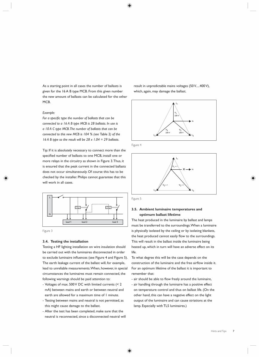
As a starting point in all cases the number of ballasts is
given for the 16 A B type MCB. From this given number
the new amount of ballasts can be calculated for the other
MCB.
Example:
For a specifi c type the number of ballasts that can be
connected to a 16 A B type MCB is 28 ballasts. In use is
a 10 A C type MCB. The number of ballasts that can be
connected to this new MCB is 104 % (see Table 2) of the
16 A B type so the result will be 28 x 1.04 = 29 ballasts.
Tip: If it is absolutely necessary to connect more than the
specifi ed number of ballasts to one MCB, install one or
more relays in the circuitry as shown in Figure 3. Thus, it
is ensured that the peak current in the connected ballasts
does not occur simultaneously. Of course this has to be
checked by the installer. Philips cannot guarantee that this
will work in all cases.
load 1 load 2 load 3
L
N
Figure 3
3.4. Testing the installation
Testing a HF lighting installation on wire insulation should
be carried out with the luminaires disconnected in order
to exclude luminaire infl uences (see Figure 4 and Figure 5).
The earth leakage current of the ballast will, for example,
lead to unreliable measurements. When, however, in special
circumstances the luminaires must remain connected, the
following warnings should be paid attention to:
- Voltages of max. 500 V DC with limited currents (< 2
mA) between mains and earth or between neutral and
earth are allowed for a maximum time of 1 minute.
- Testing between mains and neutral is not permitted, as
this might cause damage to the ballast.
- After the test has been completed, make sure that the
neutral is reconnected, since a disconnected neutral will
result in unpredictable mains voltages (50 V.....400 V),
which, again, may damage the ballast.
V1230 V
V3230 V
V2230 V
Ll
L2L3
N
Figure 4
V1 = ?
V2 = ?V3 = ?
Ll
L2L3
Nx
Figure 5
3.5. Ambient luminaire temperatures and
optimum ballast lifetime
The heat produced in the luminaire by ballast and lamps
must be transferred to the surroundings. When a luminaire
is physically isolated by the ceiling or by isolating blankets,
the heat produced cannot easily fl ow to the surroundings.
This will result in the ballast inside the luminaire being
heated up, which in turn will have an adverse effect on its
life.
To what degree this will be the case depends on the
construction of the luminaire and the free airfl ow inside it.
For an optimum lifetime of the ballast it is important to
remember that:
- air should be able to fl ow freely around the luminaire,
- air handling through the luminaire has a positive effect
on temperature control and thus on ballast life. (On the
other hand, this can have a negative effect on the light
output of the luminaire and can cause striations at the
lamp. Especially with TL5 luminaires.)

Hints and Tips8
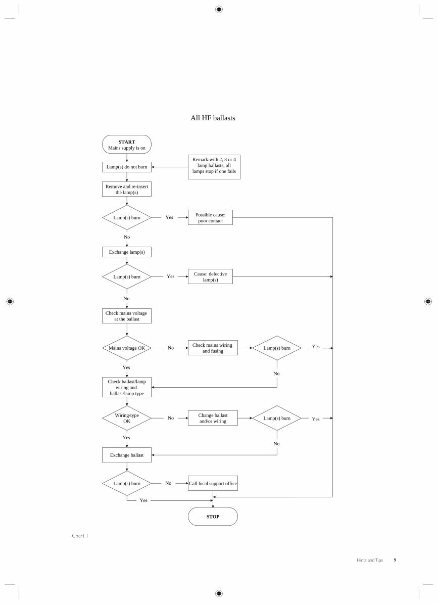
3.6. Trouble shooting
By following the fl ow charts on the next pages
possible installation problems can be traced and solved
systematically if a lighting installation equipped with HF
ballasts does not work properly (Chart 1). As regulating
ballasts may create their own problems, a separate
trouble-shooting fl ow chart has been included for them as
well (Chart 2).
Hints and Tips 9
STARTMains supply is on
Lamp(s) do not burn
Remove and re-insert the lamp(s)
Possible cause: poor contact
Remark:with 2, 3 or 4 lamp ballasts, all
lamps stop if one fails
Lamp(s) burn Yes
Exchange lamp(s)
No
Lamp(s) burn Cause: defective lamp(s)
Yes
Check mains voltage at the ballast
No
Mains voltage OK
Wiring/typeOK
Lamp(s) burn
Lamp(s) burn
Check mains wiring and fusing
No
Check ballast/lampwiring and
ballast/lamp type
Yes
Lamp(s) burn
Exchange ballast
Yes
Change ballastand/or wiring
No
Call local support office
STOP
No
Yes
Yes
Yes
No
No
All HF ballasts
Chart 1

Hints and Tips10
Extension for 1-10V regulating ballasts
START
Lamp(s) can not be dimmed
Short circuit dimmingwiring between ballastand control device atthe control device
Lamp(s) dimChange the + and – of
the control wires atthe control device
Short circuit dimminginput on ballast
Yes
No
Lamp(s) dim
Lamp(s) dim
Exchange ballastCheck and modify
wiring between ballast and control
Lamp(s) dim
Call localsupport office
STOP
YesNo
No
Yes
Short circuit dimminginput on ballast
No
START
Lamp(s) always dims
Disconnect dimmingwiring at
control device
Lamp(s) still dimRe-connect wiring
with + and –reversed
Loosen dimmingwiring on ballast
Yes
No
Dimming function
OK
Lamp(s) still dim
Check dimming wiringfrom ballast to control
device on correct +/- 10V DC voltage
Exchange ballast
Dimmingfunction
OK
Call localsupport office
STOP
Yes
No
No
Yes
Yes Yes
Exchangecontrol device
No
Chart 2

Hints and Tips 11
4.1. Electromagnetic compatibility
Electromagnetic compatibility, EMC, is the ability of
a device or system to operate satisfactorily in its
electromagnetic environment (see Figure 6), without
causing unacceptable interference in practical situations.
Phillips HF electronic ballasts fulfi l the requirements with
regard to electromagnetic compatibility as laid down in
European Norms EN 55015, EN 55022, IEC 61000-3-2
and IEC 61547.
electricalor
electronicsystem
Figure 6
4.1.1. RFI (radio frequency interference)
The radio frequency interference (RFI) regulations as laid
down in EN 55015 concern the frequency range between
9 kHz and 30 MHz. However, nowadays more and more
electronic products are being marketed that operate
on higher frequencies, like for example communication
equipment. The RFI-requirements for this kind of
equipment are laid down in the more stringent norm EN
55022, valid for frequencies from 30 MHz up to 1000 MHz.
Philips HF electronic ballasts fulfi l the requirements of this
latter norm and are therefore the best choice if they are
to operate in an environment where other equipment is
used working on frequencies up to 1000 MHz.
Apart from these general norms, there are some specifi c
regulations in force for rooms where diagnostic or
observation equipment is placed. In VDE 0107 norms are
defi nitions for these kind of rooms. Measurements on
Philips electronic ballasts have shown that in the relevant
frequency ranges, no interference of any signifi cance
occurs.
4.1.2. Immunity
When the mains voltage deviates from its nominal value
more than the ballast tolerance permits (220 V to 240 V
± 10 %), adverse effects on lamp life, ballast life and light
output can be expected. Excessively high voltages (Umains
> 320 V) over a considerable period of time (>48 hours)
will damage the ballast. Mains transients and dips, on the
other hand, will not harm the ballast, provided they are
within the regulations of EN 61547.
4.2. Humidity
HF electronic ballasts do not have any special protection
against humidity. Nevertheless, Philips electronic ballasts
have been tested on sensitivity to humid conditions and
have proven to be able to resist a relative air humidity of
up to 95 %. Direct water ingress will, however, damage
the ballast. It is therefore wise to pay attention to a few
safeguards:
- Make sure that there can be no condensation on or in
the ballast.
- Also make sure that the ballast is mounted in such a way
that no condensed or other water can fl ow into the
ballast.
4.3. Interference with infra red remote control
equipment
Video and audio apparatus, computers and also lighting
installations nowadays often operate on infrared remote
control. The frequencies of such infrared signals are in
the order of 36 kHz. In order to avoid any interference
with this kind of equipment, the operating frequency of
all Philips HF electronic ballasts has been chosen so that
problems in the 36 kHz frequency area are out of the
question.
4.4. Interference with translation / congress
systems
Translation/congress systems operate at IR frequencies
that might interfere with regulating control gear. Common
frequencies of such systems are: 55 – 95 – 135 – 175
– 215 – 255 – 295 – 335 and 375 kHz.
4. The lighting installation and environment

Hints and Tips12
Hints:
- It is advised not to apply HF regulating ballasts in areas
where the translation/congress systems mentioned are
in use.
- The lower frequency bands between 55 and 175 kHz of
translation systems should not be used in rooms where
electronic ballasts have been installed.
4.5. Norms, standards and approvals
Philips HF electronic ballasts comply with all relevant
international rules and regulations as shown in Table 3.
Safety IEC 61347-2-3
Performance IEC 60929
Harmonics IEC 61000-3-2
Radio frequency interference 9kHz to 30 MHz EN 55015
Radio frequency interference 30 MHz to
1000MHz
EN 55022
Immunity for: mains transients, voltage dips,
electrostatic discharge
IEC 61547
Vibration test IEC 60068-2-6 Fc
Bump tests IEC 60068-2-29 Eb
Emergency lighting IEC 60598-2-22
Approvals ENEC*
CE**
VDE-EMV
Quality standard ISO 9001
Environment management system ISO 14001
Table 3
*ENEC is the abbreviation of European Norm
Electrotechnical Certifi cation. More than twenty
Certifi cation bodies from CENELEC member countries
have joined the ’Agreement on the use of a commonly
agreed mark of conformity for luminaires complying with
European standards’. This agreement is in short referred
to as the LUM agreement. It means that if the ENEC
marking is given by one Certifi cation body, it is also
recognised by all the other members. The marking can be
obtained for luminaires for which a European Norm (EN)
exists, with the exception of luminaires for emergency
lighting. In 1995 the LUM group and the LVE-AC (Low
Voltage Electrical Equipment Advisory Committee)
decided that luminaire accessories like gear, ignitors,
lamp holders, electronic converters and capacitors can
obtain the ENEC marking if they fulfi l the harmonised
EN standards. Philips HF electronic ballasts received the
ENEC marking on the basis of complying with IEC 61347-
2-3, IEC 60929 and the ISO 9001 certifi cate.
**All Philips HF electronic ballasts carry the CE marking.
CE is the abbreviation of Conformité Européenne.
It states conformity of products to the essential
requirements of the European Community Directives.
It is a kind of passport for goods to circulate freely
throughout the European Union. Furthermore, it enables
Market Controlling Bodies to carry out their inspection
more easily. Lighting products are covered by three
European directives: the Electromagnetic Compatibility
(EMC) Directive, the Low Voltage (LV) Directive and the
ballast directive. Philips HF electronic ballasts carry the
CE marking on the basic of fulfi lment of the following
standards: IEC 61547, IEC 61000-3-2, EN 55015 (tested
in a reference luminaire described by CISPR 30) and
EN 50294.

Hints and Tips 13
5.1. Emergency lighting
Most electronic ballasts are suitable for use in emergency
lighting installations. Distinction must, however, be made
between centralised and decentralised emergency lighting.
Provided the correct voltages are applied, electronic
ballasts can be used in centralised installations. When
talking about a decentralised emergency lighting set-up,
many different confi gurations are possible. In general the
emergency converter must have a four-pole switchover
relay to ensure that the wiring between the HF ballasts
and the lamp is completely shut off when the emergency
lighting is in operation. Interference from the emergency
converter to the HF ballast is then eliminated. Three-
pole switchover relay should not be used in combination
with HF electronic ballasts unless the lamp is normally
connected with only three wires to the ballast.
5.2. HF Ballasts and dimming
Fluorescent lamps can be dimmed with dimmable HF
electronic ballasts, such as the Philips HF-REGULATOR
types. Philips HF-REGULATOR ballasts can be controlled
by a 1-10 V DC, DALI or Touch and Dim input from
various types of regulating systems. The control wiring
must be dealt with like 230 V wiring. For more information
on the installation of different control systems, see the
Application Guide to Fluorescent lamp control gear or
contact your local sales agent.
Figure 7
Hint:
If a 1-10 V DC signal is used, the dimming control wiring
in the installation should be kept separate from the
mains wiring when the length of the wires exceeds 5 m.
Otherwise, interference between mains and dimming
wiring might occur. This could cause light fl icker or 100 Hz
modulation.
Tip:
If separation of the wiring is not possible, use shielded
control wiring.
5. Other basic aspects

Hints and Tips14
Since the HF-Matchbox ballasts are also used without
housing, it is not possible to stamp on the ballast the
ballast type. To solve this issue a colour coding on the
mains terminals is being used. The only thing you need
to know is the size of the PCB (Printed Circuit Board),
whether it is an HF-Matchbox red or blue and the colour
coding part at the mains terminals. The mains terminals
itself are orange. In the table below (Table 4) you can fi nd
the translation from colour coding in combination with
size to type.
Type Size (L x W x H) Colour code
HF-Matchbox RED 109 56 x 36 x 20 Black
HF-Matchbox RED 113 56 x 36 x 20 Grey
HF-Matchbox RED 114 56 x 36 x 20 Blue
HF-Matchbox RED 118 56 x 36 x 20 Orange
HF-Matchbox RED 124 70 x 36 x 20 Red
HF-Matchbox BLUE 105 120 x 18 x 20 Black
HF-Matchbox BLUE 109 120 x 18 x 20 Blue
HF-Matchbox BLUE 114 120 x 18 x 20 Grey
HF-Matchbox BLUE 121 160 x 18 x 20 Grey
HF-Matchbox BLUE 124 160 x 18 x 20 Orange
HF-Matchbox BLUE 128 160 x 18 x 20 Blue
HF-Matchbox BLUE 105 56 x 36 x 20 Black
HF-Matchbox BLUE 109 56 x 36 x 20 Blue
HF-Matchbox BLUE 114 56 x 36 x 20 Grey
HF-Matchbox BLUE 118 56 x 36 x 20 Orange
HF-Matchbox BLUE 124 70 x 36 x 20 Orange
HF-Matchbox BLUE 128 70 x 36 x 20 Blue
Table 4
Size in mm
6. Colour coding of the HF Matchbox ballasts
Hints and Tips 15
Warranty is a commercial issue and can vary according
to country, production centre, product or even customer.
Philips Lighting Electronics Europe warrants in general
that the technology and quality of electronic ballasts have
evolved tremendously over the last ten years. Together
with their high effi ciency this makes electronic ballasts
the most economic solution to drive discharge lamps.
To demonstrate our confi dence in the reliability of our
products Philips now offers an extended guarantee. Philips
was the fi rst company to develop electronic ballasts.
Right from the start Philips offered service and support
wherever necessary and continues to do so. The high
quality and technology standards of the Philips Lighting
electronic ballasts of today will now be more explicitly
refl ected in a 3 and 5-year guarantee. This guarantee
applies to all Philips Lighting electronic ballasts and will
benefi t the OEM, the installer and the end-user. Since
Philips has always maintained a very high service and after
sales support level this more explicit guarantee is really
nothing new. Business as usual!
7.1. 3 year warranty
The 3-year guarantee applies to any Philips Lighting
electronic ballast. No registration is necessary. An invoice
that shows the number of ballasts etc. (see leafl et for
further details) is suffi cient. The start of the guarantee
period is the purchase date of the products.
7.2. 5 year warranty
The 5-year guarantee applies to Philips Lighting electronic
ballasts when used in registered projects, provided IEC
compliant lamps are installed. The start of the guarantee
period is the registered date of the commissioning of
the lighting installation. Registration will take place via a
specially designed registration form, which should be sent
to the Philips offi ce mentioned on the form, within two
months of the installation of the project.
Although the 5-year guarantee is valid with all IEC
compliant lamps, a Philips lamp and ballast combination
will always give optimum performance because they have
been designed around each other, within the IEC limits. A
failure with such a tuned lamp and ballast combination is
therefore less likely.
The registration form can be found via various Philips
Lighting Electronics websites such as:
http://www.dimming.philips.com
http://www.philips.com/fl uo-gear
http://www.lampsandgear.com
7. Warranty

Hints and Tips16
Readers who want further information or support on
installation aspects of HF electronic ballasts, are invited to
contact their local Philips support offi ce.
Also, for further reading the following printed
documentation is available on request:
- Application guide to fl uorescent lamp control gear. This
120 pages counting booklet explaining all application
and installation aspects in depth, ordering number
3222 635 59771 or as PDF fi le available at
http://www.philips.com/fl uo-gear.
- MultiDim Installation and Design Manual for extensive
information on DALI and the MultiDim system. This
74 pages counting document can be downloaded as a
PDF fi le from http://www.dimming.philips.com.
- MultiDim User Software Manual a special manual on
the usage of the PC software available for the MultiDim
system. This 118 pages counting document can be
downloaded as a PDF fi le from
http://www.dimming.philips.com.
- Product information leafl ets of the individual ballast
types. Folders with technical details, ordering numbers as
per item.
- OEM catalogue, which is a collection of all datasheets/
product leafl ets of the currently available products.
8. More information or support needed?

EUROPEAustria Philips Licht GmbH
Triester Straße 64 A-1101 Wien
Tel: +43.1.60101.0Fax: +43.1.60101.1166E-Mail: [email protected]
Belgium Philips Belgium NV
Div. Philips Lighting Tweestationsstraat 80/Rue des Deux Gares 80
1070 BrusselTel: +32.2.525.7669Fax: +32.2.525.7695
Czech Republic Ceská Republika
Philips Lighting s.r.o. Safrankova 1
155 55 Praha 5Tel: +42.02.33099282Fax: +42.02.33099325E-Mail: [email protected]
Denmark Philips Lys A/S Frederikskaj 6
DK-1780 Copenhagen VTel: +45.33.29.37.19Fax: +45.33.29.39.31E-Mail: [email protected]
Finland OY Philips AB Sinikalliontie 3
FIN-02631 EspooTel: +358.9.615800Fax: +358.9.61580940E-Mail: [email protected]
France Philips Eclairage
Direction Lampes OEM et Ballasts 9 rue Pierre Rigaud
94856 Ivry-sur-Seine CedexTel: +33.1.49876460Fax: +33.1.49876461E-Mail: [email protected]
Germany Philips Licht
Unternehmensbereich der Philips GmbH Luebeckertordamm 5
D-20099 HamburgTel: +49.40.2899.2886Fax: +49.40.2899.2890E-Mail: [email protected]
Greece Philips Hellas S.A. Lighting Department Kifi sias Avenue 44
Building B, 4th Floor 151 25 Marousi AthensTel: +30 210 6162450Fax: +30 210 6162490E-Mail: [email protected]
Hungary Philips Magyarország Kft. H-1119 Budapest
Fehérvári út 84/aTel: +36.1.382.1856Fax: +36.1.382.1851E-Mail: [email protected]
Ireland Philips Electronics Ireland Limited Newstead Clonskeagh
Dublin 14Tel: +353.1.764.0000Fax: +353.1.764.0121E-Mail: [email protected]
Italy Philips S.P.A.-Divisione Lighting Via G. Casati, 23
20052 Monza (MI)Tel: +39.039.2031Fax: +39.039.2036127
The Netherlands Philips Nederland B.V.
Licht O.E.M. Boschdijk 525
Postbus 900505600 PB EindhovenTel: +31.40.27.83110Fax: +31.40.27.82273
Norway Philips Norge AS Division Lys Sandstuveien 70
Postboks 1, ManglerudN-0612 OsloTel: +47.22.748000Fax: +47.22.748229E-Mail: [email protected]
Poland Philips Lighting Poland S.A. Ul. Kossaka 150
64-920 PilaTel: +48.67.351.3263Tel: +48.67.351.3756Fax: +48.67.351.3104E-Mail: [email protected]
Russia Philips Lighting Export Eastern Europe Ltd. 35 Usacheva St. 119048 Moscow Tel: +7095.9379300 Fax: +7095.9379359 E-Mail: ivan.panfi [email protected]
Spain PHILIPS IBÉRICA
División Comercial Alumbrado O.E.M. Martínez Villergas, 49
Madrid 28027Tel: +34.91566.9688/782Fax: +34.91566.9242E-Mail: [email protected]
Sweden Philips AB Division Ljus Kottbygatan 7, Akalla
S-16485 StockholmTel: +46.8.5985.2000Fax: +46.8.5985.2760E-Mail: [email protected]
Switzerland Philips SA Lighting Allmendstrasse 140 Postfach
CH-8027 ZürichTel: +41.1.4882211Fax: +41.1.4883249Web: www.lighting.philips.chE-Mail: [email protected]
Turkey Türk Philips TIC.A.S. Yukuri Dudullu Organize sanayi Bolgesi
2. Cadde No: 28 81260 Umraniye, IstanbulTurkyeTel: +90.216.522.18.51Fax: +90.216.522.18.35E-Mail: [email protected]
United Kingdom Philips Lighting UK Philips Centre Guildford
Business Park GuildfordSurrey, GU2 8XHTel: +44 1293 776774Fax: +44 1483 575534E-Mail: [email protected]
NORTH AMERICACanada Philips Electronics Limited 281 Hillmount Road
Markham, Ontario L6C 2S3Tel: +905 201 4500Fax: +905 887 7943
United States Philips Lighting Company 200 Franklin Square Drive
PO Box 6800Somerset NJ 08875-6800Tel : +1.732.563.3506
Fax: +1.732.563.3740
Advance Transformer Co. (A Division of Philips Electronics North America Corporation) O’Hare International Center 10275 West Higgins Road Rosemont, Illinois 60018 Tel: +1.800.322.2086 Fax: +1.888.423.1882
LATIN AMERICABrazil Philips Lighting Rua Verbo Divino, 1400-6th fl oor
Chacara Santo Antonio04719-002 - São Paulo - SP - BrasilTel: +55.11.5188.0633Fax: +55.11.5188.0675
ASIAHong Kong Philips Lighting Asia Pacifi c OEM Lighting
Level 6, Three Pacifi c Place1 Queens Road EastGPO BOX 2108 WanchaiTel: +852.2821.5888
Fax: +852..2866.7361
MIDDLE EAST & AFRIKA Philips Lighting Mathildelaan 1
5611 BD EindhovenTel: +31.40.2756508
Fax: +31.40.2755453 E-Mail: [email protected]
Contact details for your local Philips Lighting Offi ce

© 2006 Koninklijke Philips Electronics N.V. All rights reserved. Reproduction in whole or in part is prohibited without the prior written consent of the copyright owner.The information presented in this document does not form part of any quotation or contract, is believed to be accurate and reliable and may be changed without notice. No liability will be accepted by the publisher for any consequence of its use. Publi-cation there of does not convey nor imply any license under patent- or other industrial or intellectual property rights.
Always check that product specification is up-to-date before ordering: www.philips.com/lighting3222 635 06321 * OKT 2006