Embed Size (px)
Citation preview

Page | 1
HINDUSTAN COPPER LIMITED
(A Government of India Enterprise)
VOL - I
NIT FOR
DEVELOPMENT OF UNDERGROUND MINE AT CHAPRI
AND
PRODUCTION OF ORE FROM STOPES,
INDIAN COPPER COMPLEX, JHARKHAND
NIT No.: HCL/CO/M&C/CHAPRI/ICC/2018 Dated : 22.09.2018

Page | 2
HINDUSTAN COPPER LIMITED
(A Government of India Enterprise)
‘Tamra Bhawan’
1, Ashutosh Chowdhury Avenue
KOLKATA 700019
GLOBAL TENDER ENQUIRY
NOTICE INVITING TENDER
Tender Notice No.: HCL/ HCL/CO/M&C/CHAPRI/ICC/2018 Dated 22/09/2018
Hindustan Copper Limited (HCL), a Public Sector Undertaking under the administrative control of the
Ministry of Mines, was incorporated on 9th November 1967. It is the only vertically integrated copper
producing company in India with presence in mining, beneficiation, and smelting, refining and downstream
saleable products. HCL holds all the operating mining leases of copper in India.
HCL invites e-Tenders from experienced Global bidders under two bid systems for DEVELOPMENT
OF UNDERGROUND MINE AT CHAPRI AND PRODUCTION OF ORE FROM STOPES, at
INDIAN COPPER COMPLEX, JHARKHAND, India over a period of Sixty (60) months . The
interested contractors are requested to note the following:
1. The bid will consist of two parts, i.e. Part- I (Techno Commercial bid) and Part – II (Price bid).
Under two bid system, the first bid (the “Techno Commercial Bid") of the process involves
qualification of interested bidders in accordance with the provisions of the pre-qualification criteria
(PQC) stipulated in the tender and the second bid is the “Price Bid”. The offers are to be
submitted on line at URL https://eps.buyjunction.in of M/s. Mjunction Services Limited,
Kolkata, who are our service provider for Enterprise Procurement System. The documents
pertaining to “Techno Commercial Bid" (only Part I Bid) are to be submitted in sealed packet at
address mentioned in Tender. The price bid at above e- procurement portal will be opened only of
those bidders who qualify techno commercially. Please refer clause no. 2.6 for detailed procedure
for submission of offers.
2. The Tender document can be purchased from the office of the Executive Director (Materials &
Contracts), HCL, Kolkata as per clause 1.13 on any working day on payment of Rs 5000/- (Rupees
Five Thousand only) inclusive of 18% GST through non refundable demand draft/banker’s cheque
in favor of “Hindustan Copper Limited”, payable at Kolkata. The bidders purchasing the document
from HCL shall submit along with the Part-I bid of the tender, the original receipt for payment of
Rs. 5000/- (Rupees Five Thousand only) to HCL towards the cost of the tender document. Tender
document can also be downloaded from the HCL website (http://www.hindstancopper.com).
Bidders who download the tender document from the HCL website must submit a tender document
fee of the same amount (Rs 5000/-) inclusive of 18% GST in the form of a non-refundable
demand draft/banker’s cheque drawn on any schedule commercial bank payable at Kolkata along
with their Part-I bid of the tender. The tenders not accompanied by the tender document fee as
specified above shall be considered as non-responsive and summarily rejected. Tender documents
are strictly non-transferable. i.e. offer can be submitted only by the bidders to whom tender
documents have been issued.
It will be presumed that the bidder have gone through the entire bidding documents available in the
website which shall be binding on them.

Page | 3
3. Addresses for Communication:
a. Interested bidders may obtain further information from:
Executive Director (Materials & Contracts)
Hindustan Copper Limited
‘Tamra Bhawan’
1, Ashutosh Chowdhury Avenue
Kolkata – 700 019
Email [email protected]
Tel: +91 33 22900397
Mobile: +91 94330 01147
b. The e-bids (including the Part – II Price Bid) have to be submitted in the e tendering portal and
the documents pertaining to Part – I (Techno Commercial Bid) of the tender must be submitted
on or before as per schedule mentioned in clause 1.13 at the above mentioned address or
dropped in the tender box located on the 3rd floor of ‘Tamra Bhawan’.
The Tenders shall be opened as per schedule mentioned in clause 1.13. However, in the
eventuality of the day of opening of the tenders becomes a non-working day due to a force
majeure event, the date of opening of the tenders will shift to the next working day at the same
time.
c. All communications, including the tenders should have the following information super scribed
at the top of the packet in bold letters:
“TENDER No: HCL/CO/M&C/CHAPRI/ICC/2018 Dated 22/09/2018
For DEVELOPMENT OF UNDERGROUND MINE AT CHAPRI AND PRODUCTION OF ORE
FROM STOPES, at INDIAN COPPER COMPLEX, JHARKHAND.”
The name and address of the bidders should be clearly mentioned at the left side of the packet.
d. Official website for notices:
All notice related to this tender including Clarifications / Amendments / Corrigendum to the tender
document shall be available on HCL website http://www.hindustancopper.com under the heading
“Tenders”.
(D K Mahajan)
Executive Director (Materials & Contracts)
For Hindustan Copper Limited

Page | 4
DISCLAIMER
The information contained in this tender document or subsequently provided to bidder(s), whether verbally
or in documentary or in any other form by or on behalf of Hindustan Copper Limited (“HCL”) or any of its
employees or advisors, is provided to bidder(s) on the terms and conditions set out in this tender and such
other terms and conditions subject to which such information is provided.
This tender is not an agreement and is neither an offer nor invitation by HCL to the prospective bidders or
any other person. The purpose of this tender is to provide interested parties with the information that may
be useful to them in making their offers pursuant to this tender (the "Bid"). This tender includes statements,
which reflect various assumptions and assessments arrived at by HCL in relation to the Work (as defined in
the tender). Such assumptions, assessments and statements do not purport to contain all the information that
each bidder may require. This tender may not be appropriate for all persons, and it is not possible for HCL,
its employees or advisors to consider the investment objectives, financial situation and particular needs of
each party who reads or uses this tender. The assumptions, assessments, statements and information
contained in this tender may not be complete, accurate, adequate or correct. Each bidder should, therefore,
conduct its own investigations and analysis if any required with respect to the tender and should check the
accuracy, adequacy, correctness, reliability and completeness of the assumptions, assessments, statements
and information contained in this tender and obtains independent advice from appropriate sources.
Information provided in this tender to the bidder(s) is on a wide range of matters, some of which depends
upon interpretation of law. The information given is not an exhaustive account of statutory requirements
and should not be regarded as a complete or authoritative statement of law. HCL accepts no responsibility
for the accuracy or otherwise for any interpretation or opinion on law expressed herein.
HCL, its employees and advisors make no representation or warranty and shall have no liability to any
person, including any bidder or bidder under any law, statute, rules or regulations or tort, principles of
restitution or unjust enrichment or otherwise for any loss, damages, cost or expense which may arise from
or be incurred or suffered on account of anything contained in this tender or otherwise, including the
accuracy, adequacy, correctness, completeness or reliability of the tender and any assessment, assumption,
statement or information contained therein or deemed to form part of this tender or arising in any way in
the bid stage.
HCL also does not accept liability of any nature whether resulting from negligence or otherwise howsoever
caused arising from reliance of any bidder upon the statements contained in this tender.
HCL may in its absolute discretion, but without being under any obligation to do so, update, amend or
supplement the information, assessment or assumptions contained in this tender. The issue of this tender
does not imply that HCL is bound to select a Bidder or to appoint the selected bidder for the work and HCL
reserves the right to reject all or any of the bidders or bids without assigning any reason whatsoever.
The bidder shall bear all its costs associated with or relating to the preparation and submission of its bid
including but not limited to preparation, copying, postage, delivery fees, expenses associated with any
demonstrations or presentations which may be required by HCL or any other costs incurred in connection
with or relating to its bid. All such costs and expenses will remain with the bidder and HCL shall not be
liable in any manner whatsoever for the same or for any other costs or other expenses incurred by a bidder
in preparation or submission of the bid, regardless of the conduct or outcome of the bidding process.
The bidders are prohibited from any form of collusion or arrangement by a bidder (or its advisers or
consultants) in an attempt to influence the selection and award process. Giving or offering of any gift,
bribe or inducement or any attempt to do any such act on behalf of the bidder towards any officer/employee
of HCL or to any other person in a position to influence the decision of HCL for showing any favour in
relation to this tender or any other contract, shall render the bidder liable to such penalty as applicable
under applicable law and as HCL may deem proper, including but not limited to rejection of the bid and
forfeiture of its bid security (as defined in the tender).
This tender shall be governed by the laws of India.

Page | 5
Each bidder’s acceptance of delivery of this tender constitutes its agreement to, and acceptance of, the
terms set forth in this disclaimer. By acceptance of this tender, each bidder agrees that this tender and any
information herewith supersedes document(s) or earlier information, if any, in relation to the subject matter
hereof.

Page | 6
CONTENTS
This tender comprises the disclaimer set-forth hereinabove, the contents as listed below in Section I,
contract document in Section II.
Section I: Tender Invitation
Sl Clause No Particulars Page No
1 1 Introduction 9
2 1.2 Brief Description of Chapri Mine 9
3 1.3 Scope of Work 9-10
4 1.4 Special Conditions of Contract 11
5 1.5 Pre-Qualification 11-13
6 1.6-1.11 Documents for Bidding 13-17
7 1.12 Brief description of Bidding Process 17
8 1.13 Schedule of Bidding Process 17
9 1.14 Language of Bid 18
10 2.1-2.4 General 18-20
11 2.5-2.13 Preparation and Submission of Bid 20-24
12 2.14 Bid Security 24-25
13 2.15 Bid Prices 25-26
14 3 Evaluation of Bids 26-28
15 4 Fraud and Corrupt Practices 28-29
16 5 Pre-Bid Conference 29
17 6 Miscellaneous 29-30
APPENDICES
Sl Appendix No Particulars Page No
1 I Covering Letter 31-33
2 II Details of the Bidder 34
3 III Bank Guarantee for Bid Security 35-36
4 IV A Power of Attorney for Signing of Bid 37
5 IV B Power of Attorney for Lead Member of Consortium 38-39
6 IV C Joint Bidding Agreement 40-40
7 V & V A Integrity Pact 44-48
8 VI Information on Financial Qualification 57
9 VII Information for Technical Qualification 58-59
10 VIII A Statement of Legal Capacity 60
11 VIII B Proposed Site Organization 61
12 VIII C Certificate of Site Visit 62
13 VIII D Screen shot of mock submission of e-bid at Mjunction 63
14 IX Schedule of Item and Rate 64

Page | 7
Section II: CONTRACT
Sl Article No Particulars Page No
Contract 65-66
1 1 Definitions and Interpretation 67-75
2 2 Contract 76
3 3 Conditions Precedent 77
4 4 Work Site 78
5 5 Engineer-In-Charge 79
6 6 Contractor’s Obligations 80-91
7 7 HCL’s Obligations 92
8 8 Contract Price 93-98
9 9 Force Majeure 99
10 10 Material Breach and Suspension 100
11 11 Events of Default and Termination 101-102
12 12 Divestment of Rights and Interests 103-104
13 13 Mode of Payment by HCL 105
14 14 Dispute Resolution 106-107
15 15 Miscellaneous 108-112
Schedules
Sl Schedule No Particulars Page No
1 I Engineer in Charge 113-115
2 II Conditions for Employment of Labour 116
3 III Condition for Environment, Health & Safety Management 117-119
4 IV Supplies from HCL 120-121
5 V Schedule of Items and Rate 122
6 VI Escalation 123-124
7 VII Format for Bank Guarantee towards Performance Security 125-126
8 VIII Mandate Form for Electronic Payment through Internet 127-128
9 IX Price Schedule 129-181
10 Price Schedule for open items 182
Technical
Chapter No. Description Page No
01 Intent of specification 1-3
02 Special instructions to the Bidder 4-5
03 Scope of work, battery limits & obligation of Purchaser 6-21
04 Technical specification 22-23
04.01. Mining 23-42
04.02 Hoisting & handling facilities 43-57
04.03 Steel structures 58-64

Page | 8
04.04 Compressed air facilities 65-72
04.05 Civil works 73-84
04.06 Road Weigh Bridge 85-100
04.07 Water system 101-123
04.13. Power distribution, drives, control, illumination &
communication
123-227
06 Testing, commissioning, Performance guarantee & final
acceptance
228-235
07 Implementation schedule and Progress monitoring
Implementation Schedule Drawing
235-238
08 Drawings & documents to be furnished by the Bidder 238
Annexure Indicative Implementation Schedule 239

Page | 9
HINDUSTAN COPPER LIMITED
(A GOVT OF INDIA ENTERPRISE)
TENDER DOCUMENT
SECTION I –TENDER INVITATION
1. INTRODUCTION
1.1 HCL, a public sector undertaking under the administrative control of the Ministry of Mines, Govt.
of India, was incorporated on November 09, 1967. It is the only vertically integrated copper
producing company in India with presence in mining, beneficiation, smelting, refining and
downstream saleable products.
1.2 BRIEF DESCRIPTION OF CHAPRI MINE:
HCL has decided to develop an underground mine at Chapri at Indian Copper Complex (ICC),
Singhbhum district Jharkhand. The major facilities to be developed / installed are decline
development upto 6th level, underground development upto 6th level, widening & deepening of
existing eastern shaft alongwith commissioning of men winding system ,electrical substation at
surface and underground substations and UG pumping station at 4L & 6 L, Compressor house at
surface etc.
Chapri copper deposit which falls under the Rakha mining lease of HCL, is located 15.0 km away
from Ghatsila Railway station on Howrah – Mumbai main line and about 11 km from Moubhander
Smelter and township of HCL. The mine is well connected by blacktopped road with Kolkata –
Ranchi NH No. – 33 (distance from Kolkata about 230 km).
1.3 SCOPE OF WORK & METHOD OF WORKING:
1.3.1 The Selected Bidder shall be responsible for the engineering, procurement, construction, mine
development, ore production and execution of all the facilities in relation to the Project as
defined in technical specification and in accordance with the provisions of the Contract to be
entered into between the Selected Bidder and HCL in the form provided by HCL.
The brief Scope of Work will broadly include:
i) Dewatering of existing waterlogged working of Chapri block
ii) Design & Engineering
iii) Decline drivage
iv) Underground development
v) Stripping, sinking and Equipping of Eastern Shaft ( 2nd Outlet)
vi) Excavation of ventilation raises
vii) Production of ore from stopes
viii) Supply of different items / equipments, their erection & commissioning shall be carried by
bidder as per TS.
ix) Underground definition drilling
x) 100m3 ( Live capacity) ore Bin, Grizzly with 0.45m X 0.45m Opening, Bin Lining &
Rock Breaker
xi) Ore transportation from ore bin at mines to Mosabani concentrator plant

Page | 10
xii) Transportation of tailing from tailing paddock at Mosabani to tailing yard at Chapri mine
and underground back filling.
xiii) Supply, erection and commissioning of electrical facilities
xiv) Mine dewatering system
xv) Construction of various civil and industrial buildings viz. Substation, compressor house,
winder house, fan house etc.
The Detailed Scope of Work is given in Volume - II (Technical Specification).
1.3.2 (a) The Bidder can formulate a Project implementation strategy as per the best international practices
and in conformity to Indian Mining Legislation. Bidder can, while drawing mining scheme as
per 1.3.1, propose optimum mining layout including, location of ventilation raises, stope design
and other relevant parameters/layouts for approval by HCL before execution.
(b) Bidder can use permanent headgear and winders for striping, sinking, widening & lining of
eastern ventilation shafts on the following conditions:
i. Warrantee of winder and spare parts shall be applicable from the date of handing over the
winders.
ii. Ropes and worn out parts will be replaced by the contractor free of cost before handing
over the winder.
iii. Any damage is to be repaired.
(c) Successful bidder can use pumps, compressors, ventilation fans, electrical control panels and
cables during construction works subject to the condition that these items are put in operating
circuit instead of keeping in reserve. The warrantee of the above items and spares shall be
applicable from the date of handing over to HCL. The worn out parts will be replaced by the
contractor free of cost and rectification of any damage of pumps, compressors, ventilation
fans, electrical control panels before handing over to HCL.
1.4 SPECIAL CONDITIONS OF THE CONTRACT:
1.4.1 The successful bidder shall ensure safe working of man & machinery and HCL shall in no way be
held responsible for any damage/loss/accident etc of any type and/or reason including blasting
operations.
1.4.2 The successful bidder will be liable for any damage caused to the HCL’s equipment/property etc.
due to negligence of his employees.
The successful bidder shall not be entitled to any additional cost on account of shifting of
equipment from one place to another place.
The successful bidder shall ensure reliability/availability of all equipment and drilling equipment
for working at Chapri Mine during the contract period. In case of any break down of the
equipment, the same should be intimated to the Engineer-in-Charge or his representative
immediately and also immediate action is to be taken to rectify/replace the equipment to achieve
the monthly target.
The successful bidder should employ only skilled and authorized manpower for operation and
maintenance of the equipment. In case of new appointment of manpower, they should undergo
vocational training as per statute for working in mines and must undergo Initial Medical
Examination and PME.

Page | 11
For carrying out work on Sundays/holidays, the successful b idder will approach the Engineer-
in-Charge or his representatives at least two days in advance and obtain permission in writing.
1.5 PRE-QUALIFICATION
1.5.1 Scope of Bid/Offer: HCL wishes to select experienced bidder for Construction of underground
Chapri mines covering excavation like horizontal drives and cross cut, inclined raise, vertical raise
by drop raise technique, shaft sinking , decline development, stoping, stowing, including design &
engineering, supplies, erection & commissioning etc. and Ore transporation from Chapri to
Mosabani ( 18km) and transporting back tailings to Chapri, etc as per enclosed Technical
specifications detailed in the Tender on Item Rate basis.
1.5.2 Integrity Pact: Bidders shall execute an Integrity Pact Agreement with HCL in the format annexed
as Appendix - VA as a pre-qualification to the submission of their bids in accordance with the
tender. The duly executed Integrity Pact in original on non-judicial stamp paper of appropriate
value (Rs. 50/-) shall have to be submitted to HCL along with Techno-commercial bid.
1.5.3 Eligibility of Bidders: The bidder should have to fulfill the following qualification criterion:
1.5.3.1 Financial Eligibility: The prospective bidder should fulfill the following financial
eligibility criteria:
i. The average annual financial turnover of the bidder during the last three (3) audited
consecutive financial years ending 31.03.2018, shall not be less than Rs.
79,00,00,000/- (Rupees Seventy Nine Crores only) or its equivalent value in foreign
currency as per the audited annual accounts ending on 31.03.2018. In case of foreign
Bidder having calendar year as the financial year for accounting, average annual
turnover of last three financial years ending 31.12.2017 shall be considered.
Relevant documentary evidence including copies of Annual Report, containing Profit
& Loss Statement and Balance Sheets for immediately preceding three (3)
consecutive accounting years shall be furnished together with the Bid. Documentary
evidence for the above shall be annexed to the Offer in the form of a certificate from
Chartered Accountant within the meaning of the Chartered Accountants Act, 1949 (38
of 1949). TT selling rate of State Bank of India (SBI) as on the last working day of
the respective financial year/calendar year, as applicable shall be utilized for
conversion of foreign currencies into INR.
In case of a Consortium, the Lead member of the consortium must have minimum
50% of the Turnover specified in Eligibility Criteria i.e. Rs 39,50,00,000/- (Rupees
Thirty Nine Crores Fifty Lacs only) or more.
Net Sales shall be considered for the purpose of determination of Turnover.

Page | 12
ii. The Bidder (in case of consortium, the consortium) shall have positive net worth as
per their latest audited financial statement. Relevant documentary evidence in the
form of a certificate from a chartered accountant within the meaning of the Chartered
Accountants Act, 1949 (38 of 1949), shall be furnished together with the bid A Bidder
(in case of consortium, the consortium) not having positive net worth as per their
latest audited financial statement is ineligible to participate in the tender. The net
worth shall be positive for the last one financial year which shall be calculated based
on the subscribed paid up share capital plus Share Premium Plus Free Reserve Plus
unallocated Balance/ Surplus amount of profit and loss account, less (a) expenses not
written off, (b) Accumulated losses in Profit and Loss account, if not reduced from
reserves and surplus. The Revaluation Resrves, capital reserves and amount of
intangible assets like goodwill etc. will not be taken into account while calculating the
net worth.
The Bidder shall have to submit copies of relevant documents/evidences, duly certified by a
Chartered Accountant as indicated above, in support of their financial eligibility along with their
Techno-commercial bid.
1.5.3.2 Technical Eligibility: The prospective bidder should fulfill the following technical eligibility
criteria:
The bidder should have experience of successful completion of the following works (l) and (2)
mentioned below during the last seven (7) years ending 31.07.2018.
1. Sinking of one vertical shaft of minimum 150 meter depth and minimum 9 m2 in cross-
section.
And
2. Should have completed minimum 4000 meter of mine development in an underground
metal mining in a single year (Consecutive 12 months) during the last 7 years from a single
work.
And Should have produced minimum 1,90,000 tonne of ore III any year (consecutive 12
months) from stopes from any underground metal mine.
Or
Should have achieved excavation of 1000000 (Ten Lakh) Cubic meter of rock in open
cast/open pit metalliferous mine under MMR 1961 in a single year (consecutive 12
months).
And Should have the experience of drilling and blasting minimum 115mm / 165mm
Diameter hole for 30,000 m in a year in a open pit metalliferous mine.
In case, for a consortium to qualify, one of its member or combinations of members must

Page | 13
meet the above eligibility requirements as per (1) and (2) above.
For compliance of S No.1 of the Technical eligibility PQC, bidder shall be allowed to
associate with some competent agency for the job, in the form of either Consortium or Sub-
contractor. Credentials of proposed agency to be associated, shall be assessed by HCL in line
with Technical eligibility PQC at S No.1.
In case bidder himself does not have experience in Shaft sinking, the bidder shall submit
credentials of possible Sub-contractor(s) whom they can engage, along with their credentials
for Shaft sinking, which will be evaluated against S No. 1 of Technical PQC. Along with the
same, the bidder shall also have to submit an acceptance / understanding with the proposed
subcontractor that he is willing to do the job.
One Sub-contractor can give consent for working with multiple bidders and the same shall not
be reason for disqualification of the tender.
Price bid of only those bidders, with / without consortium, who successfully qualify S No. 2
of Technical eligibility PQC and have produced documents regarding engagement of possible
Sub-contractor who satisfy S No. 1 of Techinical eligibility PQC (if the bidder / Consortium
does not have sufficient experience in this respect), shall be opened.
Document to be enclosed
(a) Certificate(s) from the client of the Bidder/Consortium Member, based on the Client
certificate and as per Appendix VII to be submitted, to showcase relevant experience in
underground decline & mine development, sinking of shaft and open pit excavation
projects in the specified period, to fulfil the technical criteria.
(b) Certified copy of proof of production from the employer shall be enclosed for meeting
eligibility criteria for item iv mentioned above.
1.6 The bidders shall enclose the following in their offer as per the forms prescribed in this tender:
a. Certificate(s) from the statutory auditors of the bidder / Chartered Accountant, as per
Appendix VI, specifying the turnover of the bidder as per the audited annual accounts of the
consecutive preceding three financial years ending on 31.03.2018 or 31.12.2018 (for foreign
bidders having calendar year as financial year) as the case may be, and also specifying that the
methodology adopted for calculating such Turnover conforms to the provisions of tender.
b. The b idders should submit a Power of Attorney in non-judicial stamp paper, strictly
as per Appendix IV, duly notarized, authorizing the signatory of this tender to commit
the b idder.
c. The following conditions shall be adhered to while submitting the tender:
In responding to the tender submissions, bidders should submit the required documentary
evidence demonstrating their capabilities in accordance with the relevant applicable clauses of
the tender.

Page | 14
1.6.1 Individual bidders / Consortium are eligible to participate in tender. The definition of consortium is
as given in Article 1, i.e. Definitions and Interpretation chapter of NIT of Section II. In case of a
Foreign Listed Company, bidding as a Consortium Lead Member, it must have an Indian
Company, registered under the Company’s Act, as one of the Consortium Members.
No Foreign Listed Company will be allowed to bid as an individual.
1.6.2 Any entity(consortium or individual members of consortium in case of consortium) which has
been barred by HCL and the bar subsists as on the date of the tender by HCL, would not be
eligible to submit an offer. The bidder should submit an Affidavit declaring that no such bar
has been implied by HCL.
1.6.3 A bidder (consortium or individual members of consortium in case of consortium) should, in the
last 3 (three) years, have neither failed to perform on any contract related to HCL, as evidenced by
an arbitral or judicial authority, a judicial pronouncement or arbitration award against the bidder.
The bidder should submit an Affidavit declaring that no arbitration case is filed against them
in this respect.
1.6.4 The following conditions shall be adhered to while submitting the Tender:
(a) Bidders should attach clearly marked and referenced continuation sheets in the event
that the space provided in the prescribed forms is insufficient. Alternatively, bidders
may format the prescribed forms making due provisions for incorporation of the
requested information;
(b) Information supplied by a Bidder;
(c) In responding to the tender submissions, Bidders should demonstrate their capabilities in
accordance with Clause 3.1 below.
1.6.5 Additional Requirements for a Consortium
In case the Bidder is a Consortium, it shall comply with the following additional requirements:
(a) Number of members in a Consortium shall not exceed 4 (four) members including
leader of the consortium;
(b) Subject to provisions of sub-clause (a) above, the Application should contain the
information required for each member of the Consortium;
(c) Members of Consortium shall nominate the member who satisfies financial
eligibility criteria as prescribed in the NIT, as the lead member (the “Lead
Member”) of the Consortium, who shall hold minimum 50% of the specified
Turnover as specified in Clause 1.5.3.1 above and as per Article 1 of Definitions
and Interpretations of Section II. The nomination(s) shall be supported by a Power
of Attorney, as per Appendix IV B, duly signed by all members of the Consortium.
(d) The Bid should include a brief description of the roles and responsibilities of
individual members, particularly with reference to their financial and technical
obligations;

Page | 15
(e) An individual Bidder cannot at the same time be a member of a Consortium
applying for pre-qualification. Further, a member of a particular Applicant
Consortium cannot be a member of any other Applicant Consortium applying for
pre-qualification;
(f) Members of the Consortium shall enter into a binding Joint Bidding
Agreement/Consortium Agreement, substantially in the format specified at
Appendix IV C (the “Joint Bidding Agreement” or “JBA”/ “Consortium
Agreement” or “CA”), for the purpose of submitting the Bid and execute the
Project in case they have been selected as the successful Bidder. The JBA/CA, to
be submitted along with the Part-I Bid, shall, inter alia:
i. convey the intent to enter into the Agreement and subsequently perform all the
obligations of the selected Bidder in terms of the Agreement, in case the
Project is awarded to the Consortium;
ii. clearly outline the proposed roles and responsibilities, if any, of each member;
iii. include a statement to the effect that all members of the Consortium shall be
liable jointly and severally for all obligations of the selected Bidder in relation
to the Project in accordance with the Agreement;
iv. commit that its Members would fulfill the eligibility conditions as laid down in
Clause 1.5.3; and
(g) except as provided under this NIT and the Bidding Documents, there shall not be
any amendment to the JBA/CA.
(h) The permissible amendments to the JBA/CA under the NIT and bidding
documents shall be only with prior written consent of HCL.
(i) The Consortium Agreement shall be signed so as to be legally binding on all
members.
(j) The leader shall be authorised to incur liabilities and receive instructions and
payment for and on behalf of any & all members of the consortium.
(k) Leader of the consortium shall be overall responsible for the execution of the
Contract. The Leader and other Members of the Consortium shall be jointly and
severally liable for the execution of the Contract, but will be liable for damages in
proportion of the respective Contract Price. Each Member shall have a price for
his scope of work.
(l) A copy of the “Consortium Agreement/Joint Bidding Agreement” or
“CA/JBA” entered into by the consortium members prior to stipulated due date
of submission of bids and valid till Time for Completion of work plus Defect
liability Period for the work shall be submitted.

Page | 16
(m) For the purpose of formation of consortium, a member shall be an independent and
single legal entity as per laws of India or as per laws in the country of such
member and should have its own independent financial accounting system as per
laws of India or as per laws in the country of such member.
(n) The “Consortium Agreement/Joint Bidding Agreement” or “CA/JBA” shall clearly outline the proposed roles & responsibilities of each member. Each member of consortium must have the experience for the component of the contract that they are designated to perform. Failure to comply with this requirement may result in rejection of the Consortium’s bid.
1.6.6 The following conditions shall be adhered to while submitting the Bid:
(a) The Bidder should attach clearly marked and referenced continuation sheets in the
event that the space provided in the prescribed forms is insufficient. Alternatively,
Bidders may format the prescribed forms making due provisions for incorporation
of the requested information;
(b) In case the Bidder is a Consortium, each member should substantially satisfy the
pre-qualification requirements to the extent specified herein.
1.6.7 Change in composition of the Consortium: Change in the composition of a Consortium will not
be permitted by HCL after opening of Part-I bid and during any of its evaluation stage.
1.7 Number of Tender/Offer and cost thereof
The bidders shall be responsible for all the costs associated with the preparation of their tenders and
their participation in the bidding process. HCL will not be responsible or in any way liable for such
costs, regardless of the conduct or outcome of the bidding process.
No Bidder shall submit more than one offer. A bidder applying individually or as a member of a
Consortium shall not be entitled to submit another Application either individually or as a member of
any Consortium, as the case may be.
1.8 The Contract sets forth the detailed terms and conditions for the work, including the scope of the
selected bidder’s services and obligations.
1.9 The statements and explanations contained in this tender are intended to provide a better
understanding to the bidders about the subject matter of this tender and should not be construed or
interpreted as limiting in any way or manner the scope of services and obligations of the Contactor set
forth in the Contract.
1.10 Any omissions, conflicts or contradictions in the bidding documents including this tender are to be
noted, interpreted and applied appropriately to give effect to this intent, and no claims on that account
shall be entertained by HCL.

Page | 17
1.11 HCL shall receive bids pursuant to this tender in accordance with the terms set forth hereunder and
other documents that may be provided by HCL pursuant to this tender, including any modification,
alteration, amendment or clarification that may be issued by HCL from time to time (collectively the
"Bidding Documents"), and all bids shall be prepared and submitted in accordance with the terms of
the bidding documents within the due date of submission.
1.12 Brief description of Bidding Process
1.12.1 HCL has adopted a two-part process (collectively referred to as the "Bidding Process") for the
selection of the bidder for award of the work. The first bid (the “Techno Commercial Stage") of the
process involves the qualification of interested bidders in accordance with the provisions of the
pre-qualification criteria and the second bid is the “Price bid”. Both the bids have to be submitted
on or before the date of tender submission.
The second bid will be opened only for those bidders who have qualified techno-commercially in
the first bid. In case it necessitates any change in the scope of work or change in the terms &
conditions on the tender for some valid reasons, after opening of the tender i.e. first bid (Part I),
HCL at its sole discretion reserves the right to give an equal opportunity to the bidders to revise
price bid (Part-II) of their offers, if they so desire, depending on the change in the scope of
work/terms & conditions. At the bid stage, the aforesaid qualified bidders (hereinafter referred to as
the "Bidders") are being called upon to witness price bid opening. The bid shall be valid for a
period of not less than 180 (one hundred and eighty) days from the bid due date, and may be
extended further for aperiod of 30 days, if required by HCL. If a bidder extends the period of
validity of bid, the EMD/Bid Security shall also be extended by the bidder accordingly. A bidder
accepting such request, shall not modify its bid on its own.
1.12.2 The bidding documents include the Contract as well as all the other appendices as annexed to this
tender and all the aforesaid documents and any addenda issued subsequent to the issue of this
tender, but before the bid due date, will be deemed to form part of the bidding documents.
1.12.3 The bidder is required to deposit, along with its bid, a bid security as per Clause 2.14. The bid shall
be summarily rejected if it is not accompanied by the Bid Security.
1.12.4 Site visit: Site visit is mandatory before submission of bid. Bidders have to submit a certificate
confirming to have visited the site, duly countersigned by HCL or his representative in the
prescribed format as appendix VIII C.
1.12.5 Any query or request for additional information concerning this tender shall be submitted by e-mail
to the officer designated at clause 2.6.4.
1.13 Schedule of Bidding Process:
HCL shall endeavor to adhere to the schedule provided for under this clause. However, in case
HCL in its sole discretion undertakes any modification in the schedule specified below, the same
will be conveyed through HCL website only. Hence, bidders are requested to periodically visit

Page | 18
HCL website for any notification.
Sl. Event Description Dates
1. Issuance of tender 22.09.2018 between 10.00 am to 5.00 pm
2. Pre Bid Meeting 10.10.2018 At 15:00 Hrs.
3. Issue of Amendments, if any To be published in HCL website
4. Closing date of issuance of Tender 13.11.2018 by 5.00 pm
5. Due date of bid submission 13.11.2018 Up to 15:00 Hrs.
6. Opening of Part-I bid 13.11.2018 At 15:30 Hrs.
7. Opening of Price Bid (Part II) To be intimated to the qualified bidders
8. Issue of LOI / WO To the successful bidder
1.14 LANGUAGE OF BID The bid prepared by the bidder and all correspondence & documents related to the bid exchanged
by the bidder and the employer, shall be written in the English language. Bid submitted in any
other language is liable to be rejected. In case any printed literature furnished by the bidder, is
written in another language, it must be accompanied by a translation of its pertinent passages in
the English language and for the purposes of interpretation of the bid, such translation shall govern.
2. INSTRUCTIONS TO BIDDERS
a. GENERAL
2.1 Site visit and verification of information:
2.1.1 Bidders must visit the work site and ascertain for themselves the site conditions, location,
surroundings, climate, availability of power, water and other utilities for construction, access to
site, handling and storage of materials, weather data, applicable laws and regulations, and any other
matter considered relevant by them before submission of bid.
2.1.2 For this purpose, bidders shall communicate to HCL via notice/ e-mail indicating their intention to
visit the site along with the intended date of visit and the details of their visiting representatives at
least 3 (three) days before their intended visit.
HCL shall communicate its response to the interested bidders who are planning to visit the work
site at the earliest approving the date of visit or may specify another date as it may consider
suitable.
2.1.3 It shall be deemed that by submitting a bid, the bidder has complete understanding of the work
and only after that the bidder has :
a) Made a complete and careful examination of the bidding documents;
b) Received all relevant information requested from HCL;
c) Satisfied itself about all matters, things and information
d) Acknowledged and agreed that inadequacy, lack of completeness or incorrectness of
information provided in the bidding documents or ignorance of any of the matters shall
not be a basis for any claim for compensation, damages, extension of time for performance of its

Page | 19
obligations, loss of profits etc. by the bidders from HCL, or a ground for termination of
the Contract;
e) Acknowledged that it does not have a Conflict of Interest; and
f) Agreed to be bound by the undertakings provided by it under and in terms hereof.
2.1.4 HCL shall not be liable for any omission, mistake or error on the part of the bidder in respect of
any of the above or on account of any matter or thing arising out of or concerning or relating to
tender, or the bidding process, including any error or mistake therein or in any information or data
given by HCL.
2.2 Verification and Disqualification
2.2.1 HCL reserves the right to verify all statements, information and documents submitted by the bidder
in response to the tender or the other bidding documents and the bidder shall, when so required by
HCL, make available all such information, evidence and documents as may be necessary for such
verification. Any such verification or lack of such verification by HCL shall not relieve the bidder
of its obligations or liabilities hereunder nor will it affect any rights of HCL there under.
2.2.2 HCL reserves the right to reject any bid and appropriate the bid security if:
a. at any time, a material misrepresentation is made or uncovered, or
b. the bidder does not provide, within the time specified by HCL, the supplemental information
sought by HCL for evaluation of the Bid.
c. No deviations shall be mentioned in the price bid or any part of the tender document, otherwise
the offer will be summarily rejected.
Such misrepresentation/improper response shall lead to the disqualification of the bidder.
In case it is found during the evaluation or at any time before signing of the Contract or after its
execution and during the period of subsistence thereof, that one or more of the pre-qualification
conditions have not been met by the bidder or the bidder has made material misrepresentation or
has given any materially incorrect or false information, the bidder shall be disqualified forthwith if
LOI has not been issued to such bidder, and if the selected bidder has already been issued the LOI
or the selected bidder has entered into the Contract, as the case may be, the same shall,
notwithstanding anything to the contrary contained therein or in this tender, be liable to be
terminated, by a communication in writing by HCL to the selected bidder, without HCL being
liable in any manner whatsoever to the selected bidder. In such an event, HCL shall forfeit, invoke
and appropriate the Bid Security, or the Performance Security and/or the payments made by the
selected bidder as per the Contract, as the case may be, as damages, without prejudice to any other
right or remedy that may be available to HCL under the bidding documents and/or the Contract, or
otherwise. Forfeiture of bid Security or the Performance Security is liable to GST at applicable
rate.
2.2.3 The Contract to be executed by successful bidder as given in section II as part of the Bidding
documents shall be deemed to be part of this tender.
2.3 Clarifications
2.3.1 HCL shall endeavor to respond to the questions raised or clarifications sought by the bidders.
However, HCL reserves the right not to respond to any question or provide any clarification, and
nothing in this clause shall be taken or read as compelling or requiring HCL to respond to any

Page | 20
question or to provide any clarification.
2.3.2 HCL may, if deemed necessary by HCL, issue interpretations and clarifications to all bidders. All
clarifications and interpretations issued by HCL shall be deemed to be part of the bidding
documents. Verbal clarifications and information given by HCL or its employees or representatives
shall not in any way or manner be binding on HCL.
2.4 Amendment of Tender
2.4.1 Before bid due date, HCL may, for any reason, whether at its own initiative or in response to
clarifications requested by a bidder, modify the tender by the issuance of addendum/corrigendum.
2.4.2 Any addendum/corrigendum thus issued will be intimated to the bidders by uploading on HCL
website only.
2.4.3 In order to afford the bidders a reasonable time for taking an addendum /corrigendum into account,
or for any other reason, HCL may, extend the bid due date.
b. PREPARATION AND SUBMISSION OF BIDS
2.5 Online offers are invited through Enterprise Procurement System (EPS) of M/s. Mjunction Services
Limited (MJ), who is the service provider to HCL, under two-part bid system. All vendors are
requested to contact M/s. Mjunction Services Limited, Kolkata at the following address for
registration and obtaining user id and password to access and quote for the tender enquiry online.
The offers are to be submitted online at URL https://eps.buyjunction.in of M/s. Mjunction
Services Limited, Kolkata, who are our service provider for Enterprise Procurement System.
Registration Procedure:
1. Please visit the Link https://eps.buyjunction.in
2. Click on Register button.
3. Put your Company PAN No.
4. Click on INTERESTED Button on behalf of respective organization. It would be HCL in your case.
5. Fill up the Form, click on the next button, fill your preferred procurement category and click on submit
button.
6. Download the pdf Form and take a printout of the same on your Organizational Letterhead.
7. Duly Sign & Stamp on each page of the form
8. Attach One (1) Photocopy of your Organization PAN Card
9. Scan and email the same to [email protected] or Fax us at - 033 66106345.
10. Courier the hard copy to the below mentioned address
11. MJ New Office Address:
Godrej Waterside
Tower-I, 3rd floor, Plot No. 5,
Block-DP, Sector-V, Salt Lake City, Kolkata – 700091
NB: You do not require registering again for different tender enquiries of HCL. Registration on the website
is free of cost.
MJ Contact Person:

Page | 21
Important 1: For Registration related issues, all tenderers are requested to contact M/s. Mjunction services
limited, Kolkata, for free registration and obtaining User ID and Password. Please feel free to call at 033
66106426 (9.30 AM to 5.30 PM) or mail us at [email protected] for any assistance.
Important 2: For Bidding related issues, please call Mjunction on their Toll Free Helpline at 1800-419-
20001 (9.30 AM to 5.30 PM). You can also use their Customer Complaint Handling Portal and log in your
suggestions and complaints, if any, through this portal. You need to click on “Query” or “Complaint”,
which is available in the home page .Your issues will be resolved through the CCHP portal itself.
For Urgent Escalation on EPS please contact:
Mr. Indranil Banerjee / Ms. Sakshi Saxena
Client Relationship Manager (CRM)
Mjunction services ltd
Landphone: +91 33 66106015 (Direct)
Landphone: +91 33 66106100 (Board)
Handphone: +8584008224
Facsimile: +91 33 66011719
Email: [email protected] / [email protected]
For any further details on the tender, the interested parties may contact HCL office at (033)2283-2228.
NOTE:
1. All entries in the quotation should be entered at on-line submission form without any ambiguity and can
be corrected by the vendor till the date and time of closing. The last modified quotation will be taken
into consideration only.
2. Quotation cannot be accessed on-line after the DUE DATE.
3. Any order resulting from this enquiry shall be governed by the following terms and conditions in
addition to those mentioned in order.
4. PRICE: Price Bid shall be submitted through Enterprise Procurement System through Internet. Price
bid of Techno-commercially acceptable tenderers ONLY as assessed by HCL shall only be evaluated.
The schedule and details of e-procurement event shall be communicated by HCL/Service Provider
(Mjunction Services Ltd.) to the techno-commercially accepted bidders.
During the online Enterprise Procurement System, Price to be submitted in the Price Bid format On-line.
The interested parties should go through Terms and Conditions of the tender before submitting their
offer on-line.
The bidders should carry out mock submission of e-bid at Mjunction and screen shot of the same
should be submitted in Techno Commercial bid documents.
The bidder shall fill vendor registration form in HCL‟s website www.hindustancopper.com and
indicate the vendor code in Appendix II.
5. The bidders who strictly fulfill the Pre-qualification criteria should only submit their offer on-line on
EPS mode in two parts. The Part-I shall consist of "Techno Commercial Bid" and Part-II shall be “Price
Bid”. The bidders, in proof of their fulfillment of Pre-qualification criteria, have to furnish the required
documents off-line. The relevant documents along with the required EMD, cost of tender and a copy of
tender document duly signed and stamped on each page in acceptance of all terms and conditions and
relevant Annexures as mentioned in the Appendices, duly filled shall have to be sent in a sealed packet
to Executive Director (Materials & Contracts), Hindustan Copper Limited, “Tamra Bhawan”, 1,
Ashutosh Choudhury Avenue, Kolkata – 700 019, super scribing tender enquiry no. The bidders must
ensure that the above details and EMD are received by HCL before the due date of opening of bids (Part
I) on EPS.

Page | 22
Key features in Purchase Procedures:
- Use of On-Line Enterprise Procurement System for price bid.
- Vendors can access the evaluation statement on-line after the bid evaluation is over.
- Once the Enterprise procurement is closed, tenderers shall not be allowed to revise their price and/or
withdraw their offer for any reason whatsoever.
Format and Signing of Techno Commercial Bid (Part – I)
The bidder shall provide all the information sought under this tender. HCL will evaluate only those
bids that are received in the prescribed formats and complete in all respects.
The bid shall be typed or written in indelible ink and signed by the authorized signatory of the
bidder who shall also sign each page. The bid shall be submitted in hard bound form. In case of
printed and published documents, only the cover shall be initialed. All the alterations, omissions,
additions or any other amendments made to the bid shall be initialed by the person(s) signing the
bid.
2.6 Sealing and Marking of Techno Commercial Bid (Part-I)
2.6.1 The bidder shall submit the following documents of Techno Commercial Bid (Part-I) bid in a
packet bearing the TENDER no. “HCL/CO/M&C/CHAPRI/ICC/2018 Dtd 22/09/2018”:
i. Covering letter in the format specified under the schedule as Appendix-I
ii. Details of the bidder in the format prescribed at Appendix-II
iii. The Bid Security in the format prescribed at Appendix-III, and marked as ‘Bid Security’
on the packet.
iv. Power of Attorney for signing of bid in the prescribed format (Appendix-IV A).
v. Power of Attorney for Lead Member of Consortium in the prescribed format (Appendix-
IV B)
vi. Joint Bidding Agreement/Consortium Agreement in the prescribed format (Appendix-IV
C)
vii. Integrity Pact Agreement (Appendix–V & VA)
viii. Proof of eligibility criteria in the format prescribed at Appendix-VI & VII
ix. Statement of Legal Capacity of the bidder in the format prescribed at Appendix-VIII A
x. Proposed Site Organization in the format prescribed at Appendix-VIII B
xi. Certificate of Site visit in the format prescribed at Appendix-VIII C
xii. Screen shot of mock submission of e-bid at Mjunction at Appendix-VIII D.
xiii. A copy of the tender document with each page initialed by the person signing the
bid in pursuance of the power of attorney.
Part II (Price Bid) consisting of the quotation of prices shall only be done in the e
tendering Portal and no packet consisting hard copy of the Price Bid shall be sent to HCL
office.
2.6.2 The documents (original and/or true copy) accompanying the bid, shall be placed in hard binding
and the pages shall be numbered serially. Each page thereof shall be initialized by the authorized

Page | 23
signatory.
2.6.3 The packet shall clearly bear the following identification:
“For DEVELOPMENT OF UNDERGROUND MINE AT CHAPRI AND PRODUCTION
OF ORE FROM STOPES, at INDIAN COPPER COMPLEX, JHARKHAND, India”
and shall clearly indicate the name and address of the bidder. In addition, the bid due date should
be indicated on the right hand top corner of the packet.
2.6.4 The packet shall be addressed to:
ATTN. OF: Executive Director (Materials & Contracts)
ADDRESS: Hindustan Copper Limited
‘Tamra Bhawan’
1, Ashutosh Chowdhury Avenue
Kolkata – 700 019
Email: [email protected]
2.6.5 If the packet is not sealed and marked as mentioned above, HCL shall not assume any
responsibility for the misplacement or premature opening of the bid submitted and consequent
losses, if any, suffered by the bidder.
2.6.6 Bids submitted by fax, telex, telegram or e-mail shall not be entertained and shall be rejected.
2.7 Bid Due Date
2.7.1 Due date of submission of Bid Documents is as per clause 1.13 in the e tendering portal and at the
address mentioned above and in the manner and form as detailed in this TENDER.
2.8 HCL may, in its sole discretion, extend the bid due date by issuing an addendum/corrigendum.
2.9 Late Bids
Bids received by HCL after the Bid Due Date shall not be eligible for consideration and shall be
summarily rejected.
2.10 Modifications/Substitution/Withdrawal of Bids
2.10.1 Except where expressly permitted by these instructions, the bidder shall not make or cause to be
made any alteration, erasure or obliteration to the text of the documents prepared by HCL and
submitted by the bidder with or as part of his bid.
2.10.2 No bid shall be modified, substituted or withdrawn by the bidder on its submission on the bid due
date.
2.10.3 Withdrawal of a bid during the interval between the deadline for submission of bids and expiration
of the period of bid validity specified in the bid shall result in the forfeiture of Bid Security.
Forfeiture of bid security is liable to GST at applicable rate.
2.11 Rejection of Bids
2.11.1 Notwithstanding anything contained in the tender, HCL reserves the right to reject any bid and to
annul the bidding process and reject all the bids at any time without any liability or any obligation
for such rejection or annulment. In the event that HCL rejects all the bids or annuls the bidding

Page | 24
process, it may, in its discretion invite fresh bids.
2.11.2 HCL reserves the right not to proceed with the bidding process at any time, without notice or
liability, and to reject any bid without assigning any reasons.
2.12 Confidentiality: Information relating to the examination, clarification, recommendation and
evaluation of the Bidders shall not be disclosed to any person who is not officially concerned with
the process or is not a retained professional advisor advising HCL in relation to or matters arising
out of, or concerning the bidding process. HCL will treat all information, submitted as part of the
bid, in confidence and will require all those who have access to such material to treat the same in
confidence. HCL may not divulge any such information unless it is directed to do so by any
statutory entity that has the power under law to require its disclosure or is to enforce or assert any
right or privilege of the statutory entity and/or HCL or as may be required by law or in connection
with any legal process.
2.13 Correspondence with the Bidder: Save and except as provided in this tender, HCL shall not
entertain any correspondence with any Bidder in relation to acceptance or rejection of any Bid.
c. BID SECURITY
2.14 Bid Security
2.14.1 The Bidder shall have to furnish Rs. 50,00,000/- (Rs.Fifty Lacs) only as part of its bid, a Bid
Security in the form of a Demand Draft/Pay Order/Banker’s Cheque or a bank guarantee issued by
any scheduled commercial bank, drawn in favour of Hindustan Copper Limited and payable at
Kolkata, in the format at Appendix III (in case of “Bank Guarantee”) and having a validity
period of not less than 180 (one hundred eighty) days from the Bid Due Date, inclusive of a claim
period 60 (sixty) days, and which may be extended for a maximum period of another 30 (thirty)
days, if required by HCL.
2.14.2 HCL shall not be liable to pay any interest on the Bid Security so made and the same shall be
interest free.
2.14.3 Any bid not accompanied by the Bid Security shall be summarily rejected by HCL as non-
responsive subject to exemptions, if any, indicated in the tender documents.
2.14.4 HCL shall be entitled to forfeit, invoke and appropriate the Bid Security as damages inter alia in
any of the events specified below. The bidder, by submitting its bid pursuant to this tender, shall be
deemed to have acknowledged and confirmed that HCL will suffer loss and damage on account of
withdrawal of its bid or for any other default by the bidder during the Bid validity period as
specified in this tender. No relaxation of any kind on Bid Security shall be given to any bidder.
Forfeiture of bid security is liable to GST at applicable rate.
2.14.5 Under the following conditions, the Bid Security shall be forfeited, invoked as damages without
prejudice to any other right or remedy that may be available to HCL under the bidding documents
and/or under the Contract, or otherwise,:
(a) If a bidder engages in a corrupt practice, fraudulent practice, coercive practice, undesirable
practice.

Page | 25
(b) If a bidder withdraws its bid during the period of validity of bids as specified in this tender
and as extended on instructions of HCL;
(c) In the case of selected bidder, if it fails within the specified time limit -
(i) to sign and return the duplicate copy of the LOI; and/or
(ii) To do all such acts as are required under this tender or before signing of the Contract ;
and/or
(iii) To furnish the Performance Security within the period prescribed there for.
2.14.6 The following are exempted from submission of Cost of tender document and Bid Security:
Public Sector Undertakings /Govt. Dept/Govt. Institutions
Micro and Small Enterprises registered with Districts Industries Centers (DICs) / Khadi &
Village Industries Commissions (KVIC) / Khadi & Village Industries Board (KVIB) / Coir
Board/NSIC/Directorate of Handicrafts and Handloom or any other body specified by Ministry
of Micro, Small & Medium Enterprises (MoMSME).
Documentary evidence for the above should be submitted by the bidder for availing the exemption.
In case bid is submitted by a Consortium not having all the members as mentioned above, no
benefit for exemption from payment of cost of tender and EMD shall be extended.
2.14.7 Refund of Bid Security
The EMD provided by the Bidders along with the Bids should be returned to the unsuccessful
Bidders within 30 days from the date of opening of price Bid / placement of purchase order /
signing of the job contract, whichever is earlier.
In case of selected Bidder, Bid security will be retained till Performance Security as per Contract is
submitted, subject to extension of the validity as per the requirement.
In the event of the Bid of any party is rejected during the course of Techno-Commercial scrutiny
and evaluation, the EMD should be returned to such Bidder immediately within seven days from
the date of rejection of their offer.
2.15 BID PRICES
In the price bid, the bidder shall include all elements of cost strictly as per the scope of work
specified in technical specification. The price shall be item wise in accordance with and as stated
in the specification. The bidder will be responsible for complete execution of the job as specified
in the scope of work. The rate quoted should be valid for 180 days.
The bidder shall give the detail price schedule taking into consideration of all the element of
work and services as covered under the scope of work.
Quoted Price should be in figure.

Page | 26
The Contract Price is in accordance with commercial terms & conditions, stipulations,
specifications, requirements and other conditions of the Contract for the estimated quantities of
work and firm unit rates as given in Schedule of items.
Total Quoted Price of bidder shall include basic price, all taxes & duties, levies, freight,
Insurance etc. as applicable on base date but excluding GST.
Bidders shall quote for the entire scope on a “single responsibility” basis such that the total bid
price covers all the Contractor’s obligations mentioned in or to be reasonably inferred from the
tender documents in respect of the engineering, procurement, erection, testing,
commissioning, construction, Insurance, mine development, ore production and execution
of all the facilities in relation to the Project as defined in technical specification. This
includes all requirements under the Contractor’s responsibilities for testing, pre- commissioning
and commissioning of the equipment, insurance, training of Purchaser’s personnel,
commissioning spares, initial fill and Lubricants, special tools and tackles, where so required by
the tender documents, the acquisition of all permits, approvals and licenses, etc. up to
commissioning and such other items and services as may be specified in the tender documents.
Items against which no price is entered by the bidder will not be paid for by the Employer
when executed and shall be deemed to be covered by the prices for other items. The bidder will
execute/supply such item(s) without claiming any extra amount.
Bidder are required to quote the price for the commercial and technical obligations
outlined in the bidding documents. Deviations shall not be allowed for this package.
Bidder must clearly mention their Income Tax Permanent Account Number
(PAN) and Bank Account Number in the offer.
Supplies & Services quoted in Indian Rupee shall be quoted on “HCL, Chapri Site” basis. Base
Date of the Contract Price shall be the date of opening of Part I (Techno Commercial Bid)
of the tender.
Bidder to quote in the “Price Schedule” in Indian Rupees only.
3. EVALUATION OF BIDS
3.1 Opening and Evaluation of Bids
3.1.1 HCL shall open the Techno Commercial Bid (Part – I) on e-tendering portal and hard copy
documents of Part I received by post at HCL, as per schedule given in clause 1.13 in the presence
of the bidders who choose to attend. However, in the eventuality that the day of opening of the bids
becomes a non-working day due to a force majeure event, the date of opening of the bids will shift
to the next working day at the same time.
Part II of the bid (“Price Bid”) shall be opened in the e-tendering portal for those bidders who
qualify techno-commercially as per qualifying criteria of the tender. The date and time of opening
of Price Bid (Part – II) shall be communicated in due course of time.
3.1.2 To facilitate evaluation of bids, HCL may, in its sole discretion, seek clarifications in writing from
any / all Bidder(s) regarding its Bid.
3.2 Selection of Bidder

Page | 27
3.2.1 The bidder whose bid is adjudged as responsive and quoting the lowest Contract Price evaluated on
the basis of quantities in Schedule of Quantity and rate, for implementation of the Work shall be
declared as the selected bidder (the “Selected Bidder”).
Bids will be invited for the Project on the basis of the lowest total lump sum fee (“Contract
Price”) required by a Bidder for executing the Project. Bidders shall be required to quote in the
Price Bid the Contract Price that shall be charged by them for the execution of the Project. The
Contract Price amount shall constitute the sole criteria for evaluation of Bids. The Project shall be
awarded to the Bidder quoting the lowest Contract Price. In this tender document, the term
“Lowest Bidder” shall mean the Bidder seeking the lowest Contract Price.
Bidder shall quote for total/all items of price schedule.
Bidder to quote in the “Price Schedule” in Indian Rupees only.
Evaluation shall be done on Total Quoted price of Price Schedule which includes Basic price,
all taxes & duties, levies, freight, Insurance etc. but excluding GST.
Price for Open items shall not be considered for Evaluation of Price bids.
3.2.2 After selection, a Letter of Intent (the “LOI”) shall be issued, in duplicate, by HCL to the selected
bidder and the selected bidder shall, within 7 (seven) days of the receipt of the LOI, sign and return
the duplicate copy of the LOI in acknowledgement thereof. In the event the duplicate copy of the
LOI duly signed by the selected bidder is not received within the stipulated time, HCL may, unless
it consents to extension of time for submission thereof, appropriate/invoke the Bid Security of such
bidder as damages on account of failure of the selected bidder to acknowledge the LOI. No
correspondence will be entertained by HCL from the unsuccessful bidders. Forfeiture of bid
security is liable to GST at applicable rate.
3.2.3 After acknowledgement of the LOI as aforesaid by the selected bidder, it shall cause the selected
bidder to execute the Contract within the period of thirty (30) days. The Selected Bidder shall not
be entitled to seek any deviation, modification or amendment in the Contract.
3.2.4 Upon “Letter of Intent” being signed and returned by the successful Bidder, HCL will
discharge/return bid security to other unsuccessful bidders.
3.2.5 The selected bidder shall, for the due and proper performance and fulfillment of its obligations
during the contract period of the Work, provide an irrevocable and unconditional bank guarantee
from any scheduled commercial bank in India, in favour of HCL, for a sum equivalent to 10 (ten)
% of the total contract amount in the form set-forth in the Contract (the “Performance Security
Deposit”). Performance Security Deposit in any other format is not acceptable. Payment shall not
be released if PSD has not been deposited in totality. The Performance Security Deposit(PSD) shall
remain valid for a period of 76 months from the Appointed date and will be renewed subsequently
as per Article 6 of NIT. The selected bidder shall further extend the validity of its Performance
Security Deposit, if so required by HCL.

Page | 28
The said Performance Security Deposit shall be provided by the selected bidder within 30 (thirty)
days of the Appointed date. In the event, the selected bidder fails to provide the said Performance
Security within the time period stipulated herein, HCL may forfeit the Bid Security submitted by
the selected bidder along with their bid. Forfeiture of bid security is liable to GST at applicable
rate.
4. FRAUD AND CORRUPT PRACTICES
4.1 The Bidders and their respective officers, employees, agents and advisers shall observe the highest
standard of ethics during the Bidding Process and subsequent to the issue of the LOI and during the
subsistence of the Contract. Notwithstanding anything to the contrary contained herein, or in the LOI or
the Contract, HCL shall reject a Bid, withdraw the LOI, or terminate the Contract, as the case may be,
without being liable in any manner whatsoever to the Bidder or Selected Bidder, as the case may be, if
it determines that the Bidder or Selected Bidder, as the case may be, has, directly or indirectly or
through an agent, engaged in corrupt practice, fraudulent practice, coercive practice, undesirable
practice or restrictive practice in the Bidding Process. In such an event, HCL shall forfeit and
appropriate the Bid Security or Performance Security, as the case may be, as damages, without
prejudice to any other right or remedy that may be available to HCL under the Bidding Documents
and/or the Contract, or otherwise. Forfeiture of bid security or Performance Security is liable to GST at
applicable rate.
4.2 Without prejudice to the rights of HCL under clause 4.1 hereinabove and the rights and remedies
which HCL may have under the LOI or the Contract, if a Bidder or Selected Bidder, as the case may
be, is found by HCL to have directly or indirectly or through an agent, engaged or indulged in any
corrupt practice, fraudulent practice, coercive practice, undesirable practice or restrictive practice
during the Bidding Process, or after the issue of the LOI or the execution of the Contract, such Bidder
or Selected Bidder shall not be eligible to participate in any tender or request for proposal issued by
HCL during a period of 2 (two) years from the date such Bidder or Selected Bidder, as the case may be,
is found by HCL to have directly or indirectly or through an agent, engaged or indulged in any corrupt
practice, fraudulent practice, coercive practice, undesirable practice or restrictive practices, as the case
may be.
4.3 For the purposes of this clause 4, the following terms shall have the meaning hereinafter respectively
assigned to them:
(a) “corrupt practice” means (i) the offering, giving, receiving, or soliciting, directly or
indirectly, of anything of value to influence the actions of any person connected with
the Bidding Process (for avoidance of doubt, offering of employment to or employing
or engaging in any manner whatsoever, directly or indirectly, any official of HCL who
is or has been associated in any manner, directly or indirectly with the Bidding
Process or the LOI or has dealt with matters concerning the Contract, before or after
the execution thereof, at any time prior to the expiry of one year from the date such
official resigns or retires from or otherwise ceases to be in the service of HCL, shall be
deemed to constitute influencing the actions of a person connected with the Bidding
Process); or (ii) engaging in any manner whatsoever, whether during the Bidding
Process or after the issue of the LOI or after the execution of the Contract, as the case
may be, any person in respect of any matter relating to the Project or the LOI or the

Page | 29
Contract, who at any time has been or is a legal, financial or technical adviser of HCL
in relation to any matter concerning the Project;
(b) “fraudulent practice” means a misrepresentation or omission of facts or suppression of
facts or disclosure of incomplete facts, in order to influence the Bidding Process ;
(c) “coercive practice” means impairing or harming, or threatening to impair or harm,
directly or indirectly, any person or property to influence any person’s participation or
action in the Bidding Process;
(d) “undesirable practice” means (i) establishing contact with any person connected with
or employed or engaged by HCL with the objective of canvassing, lobbying or in any
manner influencing or attempting to influence the Bidding Process; or (ii) having a
Conflict of Interest; and
(e) “restrictive practice” means forming a cartel or arriving at any understanding or
arrangement among the Bidders with the objective of restricting or manipulating a full
and fair competition in the Bidding Process.
5. PRE-BID CONFERENCE
5.1 Pre-Bid conference of the Bidders shall be convened at a designated date, time and at the Corproate
office of HCL at Kolkata, as per schedule specified at clause 1.13. A maximum of two representatives
of each Bidder shall be allowed to participate.
5.2 During the course of the pre-Bid conference, the Bidders will be free to seek clarifications and make
suggestions for consideration of HCL. HCL shall endeavour to provide clarifications and such further
information as it may, in its sole discretion, consider appropriate for facilitating a fair, transparent and
competitive Bidding Process.
5.3 The Bidders are requested to submit any question/query by email to reach HCL as per 1.13 Schedule of
Bidding Process. Bidders desirous of obtaining clarifications on clauses of the tender enquiry
(Technical as well as Commercial) are requested to send their questions/queries for clarifications at
least 5 days prior to date of pre-bid conference and also ensure their participation in the per bid
conference. The purpose of the pre-bid conference will be to clarify the issues raised by the bidders.
However, HCL shall not be obliged to respond any queries which it receives after above deadline. Any
modifications of the tender document which may become necessary as a result of Pre-bid conference
shall be made exclusively through the issue of Addendum/Corrigendum, if any, and will be uploaded
on websites of www.hindustancopper.com and it shall become part of the bidding documents.
However, in case any query remains un-replied, it shall be construed that in respect of those queries,
the respective stipulation of the tender document shall continue to apply and/or no new stipulations
made w.r.t. those queries.
5.4 Non-attendance at the pre-bid conference will not be a cause for disqualification of a Bidder.
6.0 MISCELLANEOUS

Page | 30
6.1 The Bidding Process shall be governed by and construed in accordance with the laws of India and
the courts at Ghatsila, Jharkhand shall have exclusive jurisdiction over all disputes arising under,
pursuant to and/ or in connection with the Bidding Process.
6.2 HCL, in its sole discretion and without incurring any obligation or liability, reserves the right, at
any time, to;
(a) suspend and/or cancel the Bidding Process and/or amend and/or supplement the Bidding
Process or modify the dates or other terms and conditions relating thereto;
(b) consult with any Bidder in order to receive clarification or further information;
(c) retain any information and/ or evidence submitted to HCL by, on behalf of, and/ or in
relation to any Bidder; and/ or
(d) independently verify, disqualify, reject and/ or accept any and all submissions or other
information and/ or evidence submitted by or on behalf of any Bidder.
6.3 It shall be deemed that by submitting the Bid, the Bidder agrees and releases HCL, its employees,
agents and advisers, irrevocably, unconditionally, fully and finally from any and all liability for
claims, losses, damages, costs, expenses or liabilities in any way related to or arising from the
exercise of any rights and/ or performance of any obligations hereunder, pursuant hereto
and/ or in connection herewith and waives any and all rights and/ or claims it may have in this
respect, whether actual or contingent, whether present or future.

Page | 31
APPENDIX - I
Covering Letter
(To be placed in Part I of the Bid)
Date:
Executive Director (Materials & Contracts)
Hindustan Copper Limited
1, Ashutosh Chowdhury Avenue
Kolkata – 700019
Sub: Bid For DEVELOPMENT OF UNDERGROUND MINE AT CHAPRI AND PRODUCTION
OF ORE FROM STOPES, INDIAN COPPER COMPLEX, JHARKHAND
Dear Sir,
With reference to your tender no. ……………. dated xx.xx.2018, I/We, having examined the Bidding
Documents and understood their contents, hereby submit my/our Bid for the aforesaid Work in
prescribed format. The Bid is unconditional and unqualified.
1. I/We acknowledge that HCL will be relying on the information provided in the Bid and the documents
accompanying the Bid for selection of the Selected Bidder for the aforesaid Work, and we certify that
all information provided therein is true and correct and nothing has been omitted which renders such
information misleading and all documents accompanying the Bid are true copies of their respective
originals.
2. This statement is made for the express purpose of qualifying as a Selected Bidder for the
implementation of the aforesaid Work.
3. I/ We shall make available to HCL any additional information it may find necessary or require to
supplement or authenticate the Bid.
4. I/ We acknowledge the right of HCL to reject our Bid without assigning any reason or otherwise and
hereby waive, to the fullest extent permitted by applicable law, our right to challenge the same on any
account whatsoever.
5. I/ We declare that:
(a) I/ We have examined and have no reservations to the Bidding Documents, including any
addendum issued by HCL; and
(b) I/ We do not have any Conflict of Interest and
(c) I/We have not directly or indirectly or through an agent engaged or indulged in any corrupt
practice, fraudulent practice, coercive practice, undesirable practice or restrictive practice, in
respect of any tender or request for proposal issued by or any agreement entered into with HCL
or any other public sector enterprise or any government, Central or State; and
(d) I/ We hereby certify that we have taken steps to ensure that no person acting for us or on our
behalf has engaged or will engage in any corrupt practice, fraudulent practice, coercive
practice, undesirable practice or restrictive practice.
(e) the undertakings given by me/us along with the offer in response to the Tender for the Work
were true and correct as on the date of making the Tender and are also true and correct as on
the Bid Due Date and I/we shall continue to abide by them.

Page | 32
6. I/ We understand that you may cancel/annul the Bidding Process at any time and that you are neither
bound to accept any Bid that you may receive nor to invite the Bidders to Bid for the Work, without
incurring any liability to the Bidders.
7. I/ We certify that in regard to matters other than security and integrity of the country, have not been
convicted or indicted by a court of law and no adverse orders have been passed by a regulatory
authority which could cast a doubt on our ability to undertake the Work or which relates to a grave
offence that outrages the moral sense of the community.
8. I/ We further certify that in regard to matters relating to security and integrity of the country, we have
not been charge-sheeted by any agency of the government or convicted by a court of law for any
offence committed by us or by any of our Associates.
9. I/ We further certify that no investigation by a regulatory authority is pending either against us
or against our Associates or against our CEO or any of our Directors/ managers/ employees.
10. I/ We undertake that in case due to any change in facts or circumstances during the Bidding Process the
provisions of disqualification in terms of the guidelines referred to above are attracted, we shall
intimate HCL of the same immediately.
11. We further agree and acknowledge that the aforesaid obligations shall be in addition to the obligations
contained in the Contract.
12. I/We hereby irrevocably waive any right or remedy which we may have at any stage at law or
howsoever otherwise arising to challenge or question any decision taken by HCL in connection with
the selection of the Bidder, or in connection with the Bidding Process itself, in respect of the above
mentioned Work and the terms and implementation thereof.
13. In the event of my/our being declared as the Selected Bidder, I/We agree to enter into a Contract in
accordance that has been provided to me/us prior to the Bid Due Date. We agree not to seek any
changes in the aforesaid Contract and agree to abide by the same.
14. I/We have studied all the Bidding Documents carefully and have also surveyed the Work site. We
understand that except to the extent as expressly set forth in the tender and/or Contract, we shall have
no claim, right or title arising out of any documents or information provided to us by HCL or in
respect of any matter arising out of or concerning or relating to the Bidding Process including the
award of the Contract.
15. The Contract Price has been quoted by me/us after taking into consideration all the terms and
conditions stated in the tender, Contract, our own estimates of costs and after a careful assessment of
the site and all the conditions that may affect the work cost and implementation of the Work.
16. I/We offer a bid security of Rs. 50,00,000/- only to HCL in accordance with the tender.
17. The Bid security in the form of a Demand Draft/Pay Order/Banker’s Cheque/Bank Guarantee (strike
out whichever is not applicable) is attached.
18. In the event of I/We being declared as Selected Bidder, I/We hereby undertake and agree to provide an
irrevocable and unconditional bank guarantee as Performance Security Deposit in favour of HCL
within 30 (thirty) days from the Appointed date as per the tender.

Page | 33
19. I/ We agree and understand that the Bid is subject to the provisions of the Bidding Documents. In no
case, I/we shall have any claim or right of whatsoever nature if the Work is not awarded to me/us or
our Bid is not opened or rejected.
20. I/We agree to keep this offer valid for 180 (one hundred and eighty) days from the Bid Due Date
specified in the tender and may be extended by another 30 (thirty) days, if required by HCL.
21. I/ We hereby submit our Bid for undertaking the aforesaid work in accordance with the Bidding
Documents and the Contract. The prices of each item aggregating to the Contract Price are quoted by
me/us as provided in the schedule annexed hereto. The said Contract Price shall be payable over the
execution period and as set out in Contract. The RA bills can be payable only after receipt of security
deposit.
22. I/We hereby confirm that no change has been made in any of the formats attached with tender.
23. I/We agree and undertake to abide by all the terms and conditions of the tender and confirm that there
is no deviation in the terms and conditions.
In witness whereof, I/we submit this Bid under and in accordance with the terms of the tender.
Yours faithfully,
Date:
(Signature of the Authorized signatory)
Place:
(Name and designation of the of the Authorized signatory)
Name and seal of Bidder

Page | 34
APPENDIX - II
DETAILS OF BIDDER
(In case of Consortium, details of the Lead Member & other Members of the Consortium to be given
in separate sheets)
1. IN CASE OF INDIVIDUAL:
1.1 Name
1.2 Registration details, if any
1.3 Date of commencement of business
1.4 Permanent Account Number (PAN)
1.5 GST registration number
1.6 Copies of Balance sheet and Profit & loss account
1.7 Vendor registration number at HCL website
2. IN CASE OF PARTNERSHIP:
2.1 Name of Partners
2.2 Whether the Partnership is registered or not.
2.3 Date of establishment of firm
2.4 Permanent Account Number (PAN)
2.5 GST registration number
2.6 Copies of Balance sheet and Profit & loss account
2.7 Vendor registration number at HCL website
3. IN CASE OF LIMITED COMPANY:
3.1 Amount of paid-up capital
3.2 Name of Directors
3.3 Date of Registration of Company
3.4 Permanent Account Number (PAN)
3.5 GST registration number
3.6 Copies of the Balance sheet and Profit & loss account
3.7 Vendor registration number at HCL website
(Signature, name and designation of the Authorized Signatory)
Place:
Date: Name and Seal of the Bidder

Page | 35
APPENDIX – III
Bank Guarantee for Bid Security
(To be placed in Part I of the Bid)
In consideration of you, Hindustan Copper Limited, having its office at 1, Ashutosh Chowdhury Avenue,
Kolkata – 700019 (hereinafter referred to as “HCL”, which expression shall unless it be repugnant to the
subject or context thereof include its, successors and assigns) having agreed to receive the Bid
of_____________ a Company registered under the provision of the Companies Act, 1956 and having its
registered office at__________ (and acting on behalf of its consortium, if applicable) (hereinafter referred
to as the “Bidder” which expression shall unless it be repugnant to the subject or context thereof include
its/their executors, administrators, successors and assigns), for ,,,,,,,,,,,,,,,,,,,,(name of the
work)………………… in accordance with the tender (hereinafter referred to as “the Work”) pursuant to
the tender dated ________________issued in respect of the Work and other related documents
(hereinafter collectively referred to as “Bidding Documents”), we, ____________________ (indicate
the name of the bank), (hereinafter referred to as the “Bank”) at the request of ______________________
(Bidder), do hereby undertake to pay HCL an amount not exceeding Rs. _____________ (Rupees
____________________only) against any loss or damage caused to or suffered or would be caused to or
suffered by HCL by reason of any breach by the said Bidder of any of the terms or conditions contained in
the Bidding Documents.
1. We ___________________ (indicate the name of the bank) do hereby undertake to pay the amount due
and payable under this guarantee without any demur, merely on a demand from HCL stating that the
amount claimed is due by way of loss or damage caused to or would be caused to or suffered by HCL
by reason of breach by the said Bidder of any of the terms or conditions contained in the Bidding
Documents or by reason of the Bidder’s failure to fulfill or comply with all or any of the terms and
conditions contained in the said Bidding Documents. Any such demand made on the Bank shall be
conclusive as regards the amount due and payable by the Bank under this guarantee. However, our
liability under this guarantee shall be restricted to an amount not exceeding Rs_________________
(Rupees ________________ only). The Bank shall be liable to pay the said amount or any part thereof
only if HCL serves a written claim on the Bank, on or before _____ (indicate date falling 240 days after
the Bid Due Date).
2. We, the Bank, further agree that HCL shall be the sole judge to decide as to whether the Bidder is in
default of due and faithful fulfillment and compliance with the terms and conditions contained in the
Bidding Documents including, inter alia, the failure of the Bidder to keep its Bid open during the Bid
validity period set forth in the said Bidding Documents, and the decision of HCL that the Bidder is in
default as aforesaid shall be final and binding on us, notwithstanding any differences between HCL and
the Bidder or any dispute pending before any court, tribunal, arbitrator or any other authority. Further,
we undertake to pay to HCL any money so demanded notwithstanding any dispute or disputes raised by
the Bidder(s) in any suit or proceeding pending before any court or tribunal/relating thereto, our
liability under this present being absolute and unequivocal.
The payment so made by us under this guarantee shall be a valid discharge of our liability for payment
hereunder and the Bidder shall have no claim against us on making such payment.
3. We,______________________(indicate the name of the bank) further agree that the guarantee herein
contained shall be irrevocable and remain in full force and effect for a period of 240 (two hundred and
forty) days from the Bid Due Date inclusive of a claim period of 60 (Sixty) days or as extended for a
maximum period of another 90 (Ninety) days as required by HCL and shall continue to be enforceable
till all the dues of HCL under or by virtue of the said Bidding Documents have been fully paid and its

Page | 36
claims satisfied or discharged or the___________________________ (office/Department) certifies that
the terms and conditions of the said Bidding Documents have been fully and properly carried out by the
said Bidder and accordingly discharges this guarantee. Unless a demand or claim under this guarantee
is made on us in writing on or before the _______________________ we shall be discharged from all
liability under this guarantee thereafter.
4. We, ___________________________further agree with HCL that HCL shall have the fullest liberty
without our consent and without affecting in any manner our obligations hereunder to vary any of the
terms & conditions of the said Bidding Documents or to extend the validity period of this guarantee or
to postpone for any time or from time to time any of the powers exercisable by HCL against the said
Bidder and to forebear or enforce any of the terms and conditions relating to the said Bidding
Documents and we shall not be relieved from our liability by reason of any such variation or extension
being granted to the said Bidder or for any forbearance, act or commission on the part of HCL or any
indulgence by HCL to the said Bidder or by any such matter or thing whatsoever which under the law
relating to sureties would, but for this provision, have effect of so relieving us.
5. This guarantee will not be discharged due to the change in the constitution or winding up of the Bidder
or the Bank or any absorption, merger or amalgamation of the Bidder or the Bank with any other
person.
6. It shall not be necessary for HCL to proceed against the said Bidder before proceeding against the Bank
and the guarantee herein contained shall be enforceable against the Bank, notwithstanding any other
security which HCL may have obtained from the said Bidder or any other person and which shall, at
the time when proceedings are taken against the Bank hereunder, be outstanding or unrealized.
7. We, ___________________ (indicate the name of the Bank) lastly undertake not to revoke this
guarantee during its currency except with the previous consent of HCL in writing.
Dated the ____________Day of ______
For _______________
(Indicate the name of bank)

Page | 37
APPENDIX – IV A
Power of Attorney for signing of Bid
(To be placed in Part I of the Bid)
Know all men by these presents, We, ___________________ (name of the company and address of
the registered office) do hereby irrevocably constitute, nominate, appoint and authorize Mr. /
Ms__________ , son/daughter/wife of____________ and presently residing at ________, who is
holding the position of ________________], as our true and lawful attorney (hereinafter referred to as
the “Attorney”) to do in our name and on our behalf, all such acts, deeds and things as are necessary or
required in connection with or incidental to submission of our Bid for the “ [insert name of the work]”
proposed by the Hindustan Copper Limited (“HCL”) including but not limited to signing and submission of
all Tenders, Bids and other documents and writings, participation in Bidders' and other conferences and
providing information / responses to HCL, representing us in all matters before HCL, signing and execution
of all contracts including the Contract and undertakings consequent to acceptance of our Bid, and generally
dealing with HCL in all matters in connection with or relating to or arising out of our Bid for the said Work
and/or upon award thereof to us and/or till the execution of the Contract with HCL.
AND we hereby agree to ratify and confirm and do hereby ratify and confirm all acts, deeds and things
lawfully done or caused to be done by our said Attorney pursuant to and in exercise of the powers
conferred by this power of attorney and that all acts, deeds and things done by our said Attorney in exercise
of the powers hereby conferred shall and shall always be deemed to have been done by us.
IN WITNESS WHEREOF WE, ________________, THE ABOVE NAMED PRINCIPAL HAVE
EXECUTED THIS POWER OF ATTORNEY ON THIS _____DAY OF ______, 2018.
For _______________
(Signature)
(Name, Title and Address)
Witnesses: 1.
2.
Accepted [Notarized]
(Signature) (Name, Title and Address of the Attorney)
Notes:
• The mode of execution of the power of attorney should be in accordance with the procedure, if any, laid
down by the applicable law and the charter documents of the executants (s) and when it is so required, the
name should be under common seal affixed in accordance with the required procedure.
• Also, wherever required, the Bidder should submit for verification the extract of the charter documents
and documents such as a resolution/power of attorney in favour of the person executing this power
of attorney for the delegation of power hereunder on behalf of the Bidder.

Page | 38
APPENDIX – IV B
Power of Attorney for Lead Member of Consortium
(To be placed in Part I of the Bid)
Whereas the Hindustan Copper Limited (“HCL”) has invited Bids from bidders for DEVELOPMENT OF
UNDERGROUND MINE AT CHAPRI AND PRODUCTION OF ORE FROM STOPES, INDIAN
COPPER COMPLEX, JHARKHAND
Whereas, ____________, and____________ (collectively the “Consortium”) being members of the
Consortium are interested in bidding for the Project in accordance with the terms and conditions of the NIT
and other connected documents in respect of the work, and
Whereas, it is necessary for the members of the Consortium to designate one of them as the Lead Member
with all necessary power and authority to do for and on behalf of the Consortium, all acts, deeds and
things as may be necessary in connection with the Consortium’s Bid for the entire work and its
execution.
NOW THEREFORE KNOW ALL MEN BY THESE PRESENTS
We, M/s----------------------,having our registered office at _______and M/s. ______, having our registered
office at ____________, [the respective names and addresses of the registered office] (hereinafter
collectively referred to as the “Principals”) do hereby irrevocably designate, nominate, constitute, appoint
and authorise M/s ________, having its registered office at _________, being one of the members of the
Consortium, as the Lead Member and true and lawful attorney of the Consortium (hereinafter referred to as
the “Attorney”) and hereby irrevocably authorise the Attorney (with power to sub-delegate) to conduct all
business for and on behalf of the Consortium and any one of us during the Bidding Process and, in the
event the Consortium is awarded the Contract, during the execution of the entire work, and in this regard, to
do on our behalf and on behalf of the Consortium, all or any of such acts, deeds or things as are necessary
or required or incidental to the submission of its Bid for the entire work, including but not limited to
signing and submission of all applications, Bids and other documents and writings, participation in
Bidders’ and other conferences, respond to queries, submit information/ documents, sign and execute
contracts and undertakings consequent to acceptance of the Bid of the Consortium and generally to
represent the Consortium in all its dealings with HCL, and/ or any other government agency or any person,
in all matters in connection with or relating to or arising out of the Consortium’s Bid for the entire work
and/ or upon award thereof till the Contract is entered into with HCL.
AND we hereby agree to ratify and confirm and do hereby ratify and confirm all acts, deeds and
things lawfully done or caused to be done by our said Attorney pursuant to and in exercise of the powers
conferred by this power of attorney and that all acts, deeds and things done by our said Attorney in exercise
of the powers hereby conferred shall and shall always be deemed to have been done by us/ Consortium.
IN WITNESS WHEREOF WE THE PRINCIPALS ABOVE NAMED HAVE EXECUTED THIS POWER
OF ATTORNEY ON THIS _____ DAY OF_______ 20**.
For ________
(Name & Title)
For ________
(Name & Title)

Page | 39
Witnesses:
1.
2.
(Executants)
(To be executed by all the Members of the Consortium)
Notes:
1) The mode of execution of the power of attorney should be in accordance with the procedure, if any,
laid down by the applicable law and the charter documents of the executant(s) and when it is so
required, the same should be under common seal affixed in accordance with the required
procedure.
2) Also, wherever required, the Consortium members should submit for verification the extract of the
charter documents and documents such as a resolution/ power of attorney in favour of the person
executing this power of attorney for the delegation of power hereunder on behalf of the Consortium
members.

Page | 40
APPENDIX – IV C
Joint Bidding Agreement /Consortium Agreement
(To be placed in Part I of the Bid)
(To be executed on Non-Judicial Stamp Paper of appropriate value)
This Joint Bidding Agreement /Consortium Agreement (the “AGREEMENT”) made at ______ on this __
day of _____, 2018
AMONGST
{___________ Limited, a company incorporated under the companies Act, 1956} and having its registered
office at ________ (herein after referred to as “First Part”, which expression shall unless repugnant to the
context include its successors and permitted assigns)
AND
{___________ Limited, a company incorporated under the companies Act, 1956} and having its registered
office at ________ (herein after referred to as “Second Part”, which expression shall unless repugnant to
the context include its successors and permitted assigns)
The above mentioned parties of the FIRST and SECOND PART are collectively referred to as the
“Parties” and each is individually referred to as a “Party”.
WHEREAS:
A. Hindustan Copper Limited (HCL), invites applications by its NIT for short-listing of bidders
For DEVELOPMENT OF UNDERGROUND MINE AT CHAPRI AND PRODUCTION OF
ORE FROM STOPES, INDIAN COPPER COMPLEX, JHARKHAND, (hereinafter referred
to as the “work”)
B. The Parties are interested in jointly bidding for the work as members of a Consortium and in
accordance with the terms and conditions of the NIT, and
C. It is necessary condition under the NIT that the members of the Consortium shall enter into a Joint
Bidding Agreement and furnish a copy thereof with the Application.
NOW IT IS HEREBY AGREED as follows:
1. Definitions and Interpretations
In this Agreement, the capitalised term shall, unless the context otherwise requires, have the meaning
ascribed thereto under the bidding document .
2. Consortium
a) The Parties do hereby irrevocably constitute a consortium (the “Consortium”) for the purpose of
jointly participating in the Bidding Process for the Project
b) The Parties hereby undertake to participate in the Bidding Process only through this Consortium
and not individually and/ or through any other Consortium constituted for this Project, either
directly or indirectly or through any of their Constituents.
3. Covenants

Page | 41
The Parties hereby undertake that in the event the Consortium is declared the selected Bidder and
awarded the Work, it shall enter into an Agreement with HCL and for performing all its obligations as
the developer in terms of the Agreement for the work.
4. Roles of the Parties
The Parties hereby undertake to perform the roles and responsibilities as described below:
a. Party of the First Part shall be the Lead member of the Consortium and shall have the power of
attorney from all Parties for conducting all business for and on behalf of the Consortium during the
Bidding Process and under the Agreement when all the obligations under the agreement shall
become effective. The role of First Part shall (in the event that it is a technical member)
be________________, or (in the event that it is a financial member) be ____________________ .
b. Party of the Second Part shall be the Financial / Technical Member {delete as appropriate, based on
who is being nominated as the Lead Member} and the role of Second Part shall
be________________.
5. Joint and Several Liability
The Parties do hereby undertake to be jointly and severally responsible for all obligations and liabilities
relating to the work and in accordance with the terms of the NIT and the Agreement.
Leader of the consortium shall be overall responsible for the execution of the Contract. The Leader and
other Members of the Consortium shall be jointly and severally liable for the execution of the Contract,
but will be liable for damages in proportion of the respective Contract Price. Each Member shall
have a price for his scope of work.
The leader shall be authorised to incur liabilities and receive instructions and payment for and on behalf
of any & all members of the consortium.
6. Representation of the Parties
Each Party represents to the other Parties as of the date of this Agreement that:
a) Such Party is duly organized, validly existing and in good standing under the laws of its
incorporation and has all requisite power and authority to enter into this Agreement;
b) The execution, delivery and performance by such Party of this Agreement has been authorised by
all necessary and appropriate corporate or governmental action and a copy of the extract of the
charter documents and board resolution/ power of attorney in favour of the person executing this
Agreement for the delegation of power and authority to execute this Agreement on behalf of the
Consortium member is annexed to this Agreement, and will not, to the best of this knowledge
i. require any consent or approval not already obtained;
ii. violate any Applicable Law presently in effect and having applicability to it;

Page | 42
iii. violate any clearance, permit, concession, grant, license or other governmental authorisation,
approval, judgement, order or decree or any mortgage agreement, indenture or any other
instrument to which such Party is a party or by which such Party or any of its properties or
assets are bound or that is otherwise applicable to such Party; or
iv. create or impose any liens, mortgages, pledges, claims, security, interests, charges or
Encumbrances or obligations to create a lien, charge, pledge, security interest, encumbrances
or mortgage in or on the property of such Party, except for encumbrances that would not,
individually or in the aggregate, have a material adverse effect on the financial condition or
prospects or businesses of such Party so as to prevent such Party from fulfilling its obligations
under this Agreement;
v. this Agreement is the legal and binding obligation of such Party, enforceable in accordance
with its terms against it; and
vi. there is no litigation pending, or to the best of such Party’s knowledge, threatened to which it
or any of its Affiliates is a party that presently affects or which would have a material adverse
effect on the financial condition or prospects or business of such Party in the fulfillment of its
obligations under this Agreement
7. Termination
In case the work is awarded to the Consortium, this Agreement shall be effective from the date hereof
and shall continue in full force and effect till the execution of the Completion of the work plus defect
liability period as specified under the Agreement. However, in case the Consortium does not get
selected for award of the work, the Agreement will stand terminated and Bid Security will be returned
by HCL to the Bidder.
8. Miscellaneous
a) This Joint Bidding Agreement shall be governed by laws of India.
b) The Parties acknowledge and accept that this Agreement shall not be amended by the Parties without
the prior written consent of HCL.
IN WITNESS WHEREOF THE PARTIES ABOVE NAMED HAVE EXECUTED AND DELIVERED
THIS AGREEMENT AS OF THE DATE FIRST ABOVE WRITTEN.
SIGNED, SEALED AND DELIVERED
For and on behalf of Lead Member by: _____________________________
Signature: _____________________________
Name & Designation: _____________________________
Address: _____________________________

Page | 43
For and on behalf of Second Part by: _____________________________
Signature: _____________________________
Name & Designation: _____________________________
Address: _____________________________
Note:
The mode of execution of the Consortium Agreement/Joint Bidding Agreement should be in accordance
with the procedure, if any laid down by the applicable law and the charter documents of the
executants(s) and when it is so required, the same should be under common seal affixed in accordance
with the required procedure.

Page | 44
APPENDIX – V
(To be placed in Part I of the Bid)
INTEGRITY PACT
The Integrity Pact (“Pact”) essentially envisages an agreement between the Bidder and the owner
(“HCL”), committing the persons/officials of both the parties, not to exercise any corrupt influence on any
aspect of the Contract. Only those Bidders who have entered into such a Pact with the HCL would be
qualified to submit their bids. In other words, entering into this Pact would be a preliminary qualification.
The Pact shall be effective from the stage of invitation of Bids till the execution of the Contract. Thereafter,
the Selected Bidder shall be required to execute a separate Integrity Pact, which shall form part of, and be
appended to the Contract.
The Pact envisages a panel of Independent External Monitors (“IEM”) approved for HCL. The IEM is to
review independently and objectively, whether and to what extent the parties have complied with their
obligations under the Pact. It has right of access to all Work documentation. The IEM may examine any
complaint received by it and submit a report to the CMD of HCL, at the earliest. He may also submit a
report directly to the Chief Vigilance Officer and the Central Vigilance Commission, in case of suspicion of
serious irregularities attracting the provisions of the Prevention of Corruption Act. However, even though
the Contract may be covered by the Pact, the Central Vigilance Commission may, at its discretion, have
any complaint received by it relating to such a Contract, investigated.
The IEM on the advice of CVC has been appointed by HCL, who has been assigned by HCL to oversee
implementation of the Pact relating to the Contract, in line with the terms and conditions of the Integrity
Pact Agreement, to be signed between the Bidder and HCL.

Page | 45
APPENDIX - VA
INTEGRITY PACT AGREEMENT
Between
Hindustan Copper Limited (HCL) hereinafter referred to as “the Principal”
and
..…………………………hereinafter referred to as “The Bidder”
Preamble
The Principal intends to award, under laid down organizational procedures, Contract/s of “[insert name of
the work]”. The Principal values full compliance with all relevant laws of the land, rules, regulations,
economic use of resources and of fairness/transparency in its relations with its Bidder(s).
In order to achieve these goals, the Principal has appointed Sri M.K.Deshmukh and Sri Narendra Kothari
an Independent External Monitors (IEMs), who will monitor the tender Process and the execution of the
Contract for compliance with the principles mentioned above.
Section I – Commitments of the Principal
(1) The Principal commits itself to take all measures necessary to prevent corruption and to observe the
following principles:-
a. No employee of the Principal, personally or through family members, will in connection with the
bidding , or the execution of a contract, demand, take a promise for or accept, for self or third
person, any material or immaterial benefit which the person is not legally entitled to.
b. The Principal will, during the Bidding Process treat all Bidder(s) with equity and reason. The
Principal will in particular, before and during the Bidding Process, provide to all Bidder(s) the
same information and will not provide to any Bidder(s) confidential/additional information
through which the Bidder(s) could obtain an advantage in relation to the Bidding Process or the
Contract execution.
c. The Principal will exclude from the process all known prejudiced persons.
(2) If the Principal obtains information on the conduct of any of its employees which is a criminal
offence under the Indian Penal Code / Prevention of Corruption Act, or if there be a substantive
suspicion in this regard, the Principal will inform the Chief Vigilance Officer and in addition can
initiate disciplinary actions.
Section 2 – Commitments of the Bidder(s)
(1) The Bidder(s) commits himself to take all measures necessary to prevent corruption. He commits
himself to observe the following principles during his participation in the Bidding Process and during
the Contract execution.
The Bidder(s) will not, directly or through any other person or company, offer, promise or give to any of
the Principal’s employees involved in the Bidding Process or the execution of the Contract
a. or to any third person any material or other benefit which he/she is not legally entitled to, in order
to obtain in exchange any advantage of any kind whatsoever during the Bidding Process or during
the execution of the Contract.
b. The Bidder(s) will not enter with other Bidders into any undisclosed agreement or understanding,
whether formal or informal. This applies in particular to prices, specifications, certifications,

Page | 46
subsidiary contracts, submission or non-submission of Bids or any other actions to restrict
competitiveness or to introduce cartelization in the Bidding Process.
c. The Bidder(s) will not commit any offence under the Indian Penal Code / Prevention of
Corruption Act; further the Bidder(s) will not use improperly, for purposes of competition or
personal gain, or pass on to others, any information or document provided by the Principal as part
of the business relationship, regarding plans, technical proposals and business details, including
information contained or transmitted electronically.
d. The Bidder(s) will, when presenting his Bid, disclose any and all payments he has made, is
committed to or intends to make to agents, brokers or any other intermediaries in connection with
the award of the Contract.
(2) The Bidder(s) will not instigate third persons to commit offences outlined above or be an accessory
to such offences.
Section 3 – Disqualification from Bidding Process and exclusion from future contracts
If the Bidder(s), before award or during execution has committed a transgression through a violation
of Section 2, above or in any other form such as to put his reliability or credibility in question, the
Principal is entitled to disqualify the Bidder(s) from the Bidding Process or take action as per the
procedure mentioned in the “Guidelines on Banning of Business Dealings”.
Section 4 – Compensation for damages
a. If the Principal has disqualified the Bidder(s) from the Bidding Process prior to the award
according to Section 3, the Principal is entitled to demand and recover the damages equivalent
to Bid Security.
b. If the Principal has terminated the Contract according to Section 3, or if the Principal is
entitled to terminate the Contract according to Section 3, the Principal shall be entitled to
demand and recover from the Bidder, liquidated damages/penalties of the Contract value or the
amount equivalent to Performance Security.
Section 5 – Previous transgression
a. The Bidder declares that no previous transgressions occurred in the last 3 (three) years with
any other company in any country conforming to the anti corruption approach or with any
other public sector enterprise in India that could justify his exclusion from the Bidding Process.
b. If the Bidder makes incorrect statement on this subject, he can be disqualified from the Bidding
Process or action can be taken against them as per the procedure mentioned in “Guidelines on
Banning of Business Dealings”.
Section 6 - Equal treatment of all Bidders
a. The Bidder(s) undertake(s) to demand from all subcontractors a commitment in conformity
with this Integrity Pact Agreement, and to submit it to the Principal before execution of the
Contract.
b. The Principal will enter into agreements with identical conditions as this one with all Bidders,
c. The Principal will disqualify from the Bidding Process all Bidders who do not sign this
Integrity Pact Agreement or violate its provisions.

Page | 47
Section 7 – Criminal charges against violating Bidder(s)
If the Principal obtains knowledge of conduct of a Bidder or of an employee or a representative or
an Associate of a Bidder which constitutes corruption, or if the Principal has substantive suspicion
in this regard, the Principal will inform the Chief Vigilance Officer of the same.
Section 8 - Independent External Monitor/Monitors
a. The Principal has appointed competent and credible Independent External Monitor (“IEM”) for
this Integrity Pact Agreement. The task of the IEM is to review independently and objectively,
whether and to what extent the parties comply with the obligations under this agreement.
b. The IEM is not subject to instructions by the parties/ their representatives and performs its
functions neutrally and independently. It reports to the Chairman- cum-Managing Director of
HCL.
c. The Bidder(s) accepts that the IEM has the right of access without restriction to all Work
documentation of the Principal .The Bidder will also grant the IEM, upon its request and
demonstration of a valid interest, unrestricted and unconditional access to his Work
documentation. The same is applicable to Subcontractors. The IEM is under a contractual
obligation to treat the information and documents of the Bidder(s) with confidentiality.
d. The Principal will provide to the IEM sufficient information about all meetings among the
parties related to the Work provided that such meetings could have an impact on the contractual
relations between the Principal and the Bidders. The parties offer to the IEM the option to
participate in such meetings.
e. As soon as the IEM notices, or believes, that there is a violation of this Integrity Pact
Agreement, it will so inform the management of the Principal and request the management to
discontinue or take corrective action, or to take other relevant action. The IEM can, in this
regard, submit non-binding recommendations. Beyond this, the IEM has no right to demand
from the parties that they act in a specific manner, refrain from action or tolerate action.
f. The IEM will submit a written report to the Chairman-cum-Managing Director of HCL
within 8 to 10 weeks from the date of reference or intimation to him by the Principal and, should
the occasion arise, submit proposals for correcting problematic situations.
g. The IEM shall be entitled to compensation on the same terms as being extended to/provided to
Independent Directors of HCL.
h. If the IEM has reported to the Chairman-cum-Managing Director of HCL, a substantiated
suspicion of an offence under relevant Indian Penal Code/PC Act, and the Chairman-cum-
Managing Director of HCL has not, within reasonable time taken visible action to proceed
against such offence or reported it to the Chief Vigilance Officer, the IEM may also transmit
this information directly to the Central Vigilance Commissioner.
Section 9 - Pact Duration
This Integrity Pact Agreement begins when both parties have legally signed it. It expires for the
Selected Bidder 12 (twelve) months after the last payment under the Contract, and for all other
Bidders 6 (six) months after the Contract has been awarded.
If any claim is made/lodged during this time, the same shall be binding and continue to be valid
despite the lapse of this Integrity Pact Agreement as specified above, unless it is
discharged/determined by Chairman-cum-Managing Director of HCL.

Page | 48
Section 10 - Other provisions
a. This agreement is subject to Indian laws. Place of performance and jurisdiction is the
registered office of the Principal, i.e. Kolkata.
b. Changes and supplements as well as termination notices need to be made in writing. Side
agreements have not been made.
c. Should one or several provisions of this agreement turn out to be invalid, the remainder of this
agreement remains valid. In this case, the parties will strive to come to an agreement as to their
original intentions.
____________________________ _____________________________
(For & On behalf of the Principal) (For & On behalf of the Bidder)
(Office Seal) (Office Seal)
Witness 1: ________________________________
(Name & Address) ________________________________
________________________________
________________________________
Witness 2: ________________________________
(Name & Address) ________________________________
________________________________
________________________________

Page | 49
Annex - A
GUIDELINES FOR INDIAN AGENTS OF FOREIGN SUPPLIERS
1.0 There shall be compulsory registration of agents for all Global (Open) Tender and Limited Tender. An agent who is not registered with HCL Plants/Units shall apply for
registration in the prescribed Application –Form. 1.1 Registered agents will file an authenticated Photostat copy duly attested by a Notary
Public/Original certificate of the principal confirming the agency agreement and giving the status
being enjoyed by the agent and the commission/remuneration/salary/ retainer ship being paid by the principal to the agent before the placement of order by HCL Plants/Units.
1.2 Wherever the Indian representatives have communicated on behalf of their principals and the foreign parties have stated that they are not paying any commission to the Indian agents, and the Indian representative is working on the basis of salary or as retainer, a written declaration to this effect should be submitted by the party (i.e. Principal) before finalizing the order
2.0 DISCLOSURE OF PARTICULARS OF AGENTS/ REPRESENTATIVES IN
INDIA. IF ANY.
2.1 Tenderers of Foreign nationality shall furnish the following details in their offer: 2.1.1 The name and address of the agents/representatives in India, if any and the
extent of authorization and authority given to commit the Principals. In case the agent/representative be a foreign Company, it shall be confirmed whether it is real substantial Company and details of the same shall be furnished.
2.1.2 The amount of commission/remuneration included in the quoted price(s) for
such agents/representatives in India. 2.1.3 Confirmation of the Tenderer that the commission/ remuneration if any,
payable to his agents/representatives in India, may be paid by HCL in Indian Rupees only.
2.2 Tenderers of Indian Nationality shall furnish the following details in their offers: 2.2.1 The name and address of the foreign principals indicating their nationality as
well as their status, i.e, whether manufacturer or agents of manufacturer holding the Letter of Authority of the Principal specifically authorizing the agent to make an offer in India in response to tender either directly or through the agents/representatives.
2.2.2 The amount of commission/remuneration included in the price (s) quoted by
the Tenderer for himself. 2.2.3 Confirmation of the foreign principals of the Tenderer that the
commission/remuneration, if any, reserved for the Tenderer in the quoted price (s), may be paid by HCL in India in equivalent Indian Rupees on satisfactory completion of the Project or supplies of Stores and Spares in case of operation items .
2.3 In either case, in the event of contract materializing, the terms of payment will provide for payment of the commission /remuneration, if any payable to the agents/representatives in India in Indian Rupees on expiry of 90 days after the discharge of the
obligations under the contract. 2.4 Failure to furnish correct and detailed information as called for in paragraph-2.0
above will render the concerned tender liable to rejection or in the event of a contract materializing, the same liable to termination by HCL. Besides this there would be a penalty of banning business dealings with HCL or damage or payment of a named sum.
*******

Page | 50
Annex. B
GUIDELINES ON BANNING OF BUSINESS DEALINGS
CONTENTS
S.No. Description
1. Introduction
2. Scope
3. Definitions
4. Initiation of Banning / Suspension
5. Suspension of Business Dealings
6. Ground on which Banning of Business Dealing can be initiated
7. Banning of Business Dealings
8. Removal from List of Approved Agencies-Suppliers/
Contractors etc.
9. Show-cause Notice
10. Appeal against the Decision of the Competent Authority
11. Review of the Decision by the Competent Authority
12. Circulation of the names of Agencies with whom Business
Dealings have been banned
1. Introduction
1.1 Hindustan Copper Limited (HCL), being a Public Sector Enterprise and ‘State’, within the meaning of Article 12 of Constitution of India, has to ensure preservation of rights enshrined in Chapter III of the Constitution. HCL has also to safeguard its commercial interests. HCL deals with Agencies, who have a very high degree of integrity, commitments and sincerity towards the work undertaken. It is not in the interest of HCL to deal with Agencies who commit deception, fraud or other misconduct in the execution of contracts awarded / orders issued to them. In order to ensure compliance with the constitutional mandate, it is incumbent on HCL to observe principles of natural justice before banning the business dealings with any Agency.
1.2 Since banning of business dealings involves civil consequences for an Agency concerned, it is incumbent that adequate opportunity of hearing is provided and the explanation, if tendered, is considered before passing any order in this regard keeping in view the facts and circumstances of the case.
2. Scope

Page | 51
2.1 The General Conditions of Contract (GCC) of HCL generally provide that HCL reserves its rights to remove from list of approved suppliers / contractors or to ban business dealings if any Agency has been found to have committed misconduct and also to suspend business dealings pending investigation. If such provision does not exist in any GCC, the same may be incorporated.
2.2 Similarly, in case of sale of material there is a clause to deal with the Agencies / customers / buyers, who indulge in lifting of material in unauthorized manner. If such a stipulation does not exist in any Sale Order, the same may be incorporated.
2.3 However, absence of such a clause does not in any way restrict the right of Company (HCL) to take action / decision under these guidelines in appropriate cases.
2.4 The procedure of (i) Removal of Agency from the List of approved suppliers / contractors; (ii) Suspension and (iii) Banning of Business Dealing with Agencies, has been laid down in these guidelines.
2.5 These guidelines apply to all the Plants / Units and subsidiaries of HCL. 2.6 It is clarified that these guidelines do not deal with the decision of the
Management not to entertain any particular Agency due to its poor / inadequate performance or for any other reason.
2.7 The banning shall be with prospective effect, i.e., future business dealings. 3. Definitions
In these Guidelines, unless the context otherwise requires: ‘Party / Contractor / Supplier / Purchaser / Customer/Bidder/Tenderer’ shall mean and include a public limited company or a private limited company, a firm whether registered or not, an individual, a cooperative society or an association or a group of persons engaged in any commerce, trade, industry, etc. ‘Party / Contractor / Supplier / Purchaser / Customer/ Bidder /
Tenderer’ in the context of these guidelines is indicated as ‘Agency’. ‘Inter-connected Agency’ shall mean two or more companies having any of the following features:
If one is a subsidiary of the other. If the Director(s), Partner(s), Manager(s) or Representative(s) are common;
If management is common; If one owns or controls the other in any manner; ‘Competent Authority’ and ‘Appellate Authority’ shall mean the following:
For Company (entire HCL) Wide Banning The Director (Technical) shall be the ‘Competent Authority’ for the purpose of these guidelines. Chairman, HCL shall be the ‘Appellate Authority’ in respect of such cases except banning of business dealings with Foreign Suppliers of imported coal/coke.
For banning of business dealings with Foreign Suppliers of imported coal/coke, HCL Directors’ Committee (SDC) shall be the ‘Competent Authority’. The Appeal against the Order passed by SDC, shall lie with Chairman, as First Appellate Authority.
In case the foreign supplier is not satisfied by the decision of the First Appellate Authority, it may
approach HCL Board as Second Appellate Authority. For Plants / Units only
Any officer not below the rank of General Manager / Addl Director
appointed or nominated by the Unit Head of concerned Plant / Unit
shall be the ‘Competent Authority’ for the purpose of these guidelines.

Page | 52
The Unit Heads of the concerned Plants / Unit shall be the ‘Appellate
Authority’ in all such cases.
For Corporate Office only For procurement of items / award of contracts, to meet the requirement of Corporate Office only, Head of M&C shall be the “Competent Authority” and Director (Technical) shall be the “Appellate Authority”.
Chairman, HCL shall have overall power to take suo-moto action on any information available or received by him and pass such order(s) as he may think appropriate, including modifying the order(s) passed by any authority under these guidelines.
‘Investigating Department’ shall mean any Department or Unit investigating into the conduct of the Agency and shall include the Vigilance Department, Central Bureau of Investigation, the State Police or any other department set up by the Central or State Government having powers to investigate.
‘List of approved Agencies - Parties / Contractors / Suppliers / Purchasers / Customers / Bidders
/ Tenderers shall mean and include list of approved / registered Agencies - Parties/ Contractors / Suppliers / Purchasers / Customers / Bidders / Tenderers, etc.
4. Initiation of Banning / Suspension
Action for banning / suspension business dealings with any Agency should be initiated by the department having business dealings with them after noticing the irregularities or misconduct on their part. Besides the concerned department, Vigilance Department of each Plant / Unit /Corporate Vigilance may also be competent to initiate such action.
5. Suspension of Business Dealings
5.1 If the conduct of any Agency dealing with HCL is under investigation by any department (except Foreign Suppliers of imported coal/coke), the Competent Authority may consider whether the allegations under investigation are of a serious nature and whether pending investigation, it would be advisable to continue business dealing with the Agency. If the Competent Authority, after consideration of the matter including the recommendation of the Investigating Department, if any, decides that it would not be in the interest to continue business dealings pending investigation, it may suspend business dealings with the Agency. The order to this effect may indicate a brief of the charges under investigation. If it is decided that inter-connected Agencies would also come within the ambit of the order of suspension, the same should be specifically stated in the order. The order of suspension would operate for a period not more than six months and may be communicated to the Agency as also to the Investigating Department. The Investigating Department may ensure that their investigation is completed and whole process of final order is over within such period.
5.2 The order of suspension shall be communicated to all Departmental Heads within the Plants / Units. During the period of suspension, no business dealing may be held with the Agency.
5.3 As far as possible, the existing contract(s) with the Agency may continue unless the Competent Authority, having regard to the circumstances of the case, decides otherwise.
5.4 If the gravity of the misconduct under investigation is very serious and it would not be in the interest of HCL, as a whole, to deal with such an Agency

Page | 53
pending investigation, the Competent Authority may send his recommendation to Chief Vigilance Officer (CVO), HCL Corporate Office alongwith the material available. If Corporate Office considers that depending upon the gravity of the misconduct, it would not be desirable for all the Plants / Units and Subsidiaries of HCL to have any dealings with the Agency concerned, an order suspending business dealings may be issued to all the Plants / Units by the Competent Authority of the Corporate Office, copy of which may be endorsed to the Agency concerned. Such an order would operate for a period of six months from the date of issue.
5.6 If the Agency concerned asks for detailed reasons of suspension, the Agency may be informed that its conduct is under investigation. It is not necessary to enter into correspondence or argument with the Agency at this stage.
5.7 It is not necessary to give any show-cause notice or personal hearing to the Agency before issuing the order of suspension. However, if investigations are not complete in six months time, the Competent Authority may extend the period of suspension by another three months, during which period the investigations must be completed.
6. Ground on which Banning of Business Dealings can be initiated
6.1 If the security consideration, including questions of loyalty of the Agency to the State, so warrants;
6.2 If the Director / Owner of the Agency, proprietor or partner of the firm, is convicted by a Court of Law for offences involving moral turpitude in relation to its business dealings with the Government or any other public sector enterprises or HCL, during the last five years;
6.3 If there is strong justification for believing that the Directors, Proprietors, Partners, owner of the Agency have been guilty of malpractices such as bribery, corruption, fraud, substitution of tenders, interpolations, etc;
6.4 If the Agency continuously refuses to return / refund the dues of HCL without showing adequate reason and this is not due to any reasonable dispute which would attract proceedings in arbitration or Court of Law;
6.5 If the Agency employs a public servant dismissed / removed or employs a
person convicted for an offence involving corruption or abetment of such offence;
6.6 If business dealings with the Agency have been banned by the Govt. or any other public sector enterprise;
6.7 If the Agency has resorted to Corrupt, fraudulent practices including misrepresentation of facts and / or fudging /forging /tampering of
documents; 6.8 If the Agency uses intimidation / threatening or brings undue outside pressure
on the Company (HCL) or its official in acceptance / performances of the job under the contract;
6.9 If the Agency indulges in repeated and / or deliberate use of delay tactics in
complying with contractual stipulations; 6.10 Willful indulgence by the Agency in supplying sub-standard material
irrespective of whether pre-despatch inspection was carried out by Company (HCL) or not;
6.11 Based on the findings of the investigation report of CBI / Police against the Agency for malafide / unlawful acts or improper conduct on his part in matters relating to the Company (HCL) or even otherwise;
6.12 Established litigant nature of the Agency to derive undue benefit;
6.13 Continued poor performance of the Agency in several contracts;

Page | 54
6.14 If the Agency misuses the premises or facilities of the Company (HCL), forcefully occupies, tampers or damages the Company’s properties including land, water resources, forests / trees, etc. (Note: The examples given above are only illustrative and not exhaustive.
The Competent Authority may decide to ban business dealing for any good and sufficient reason).
7. Banning of Business Dealings
7.1 Normally, a decision to ban business dealings with any Agency should apply
throughout the Company including Subsidiaries. However, the Competent Authority of the Plant / Unit except Corporate Office can impose such ban unit-wise only if in the particular case banning of business dealings by respective Plant / Unit will serve the purpose and achieve its objective and banning throughout the Company is not required in view of the local conditions and impact of the misconduct / default to beyond the Plant / Unit. Any ban imposed by Corporate Office shall be applicable across all Plants / Units of the Company including Subsidiaries.
7.2 For Company-wide banning, the proposal should be sent by the Plant / Unit to the CVO through the Head of the Plant / Unit setting out the facts of the case and the justification of the action proposed alongwith all the relevant
papers and documents except for banning of business dealings with Foreign Suppliers of imported coal/coke. The Corporate Vigilance shall process the proposal of the Plant / Unit for a prima- facie view in the matter by the Competent Authority nominated for
Company-wide banning. The CVO shall get feedback about that agency from all other Plants / Units. Based on this feedback, a prima-facie decision for banning / or otherwise shall be taken by the Competent Authority. If the prima-facie decision for Company-wide banning has been taken, the Corporate Vigilance shall issue a show-cause notice to the agency conveying why it should not be banned throughout HCL.
After considering the reply of the Agency and other circumstances and facts of the case, a final decision for Company-wide banning shall be taken by the Competent Authority.
7.3 There will be a Standing Committee in each Plant / Unit to be appointed by Unit Head for processing the cases of “Banning of Business Dealings” except for banning of business dealings with foreign suppliers of coal/coke. However, for procurement of items / award of contracts, to meet the requirement of Corporate Office only, the committee shall be consisting of General Manager / Dy. General Manager each from Operations, Finance, Law & M&C. Member from M&C shall be the convener of the committee. The functions of the committee shall, inter-alia include:
To study the report of the Investigating Agency and decide if a prima-facie case for Company-wide / Local unit wise banning exists, if not, send back the case to the Competent Authority.
To recommend for issue of show-cause notice to the Agency by the concerned department.
To examine the reply to show-cause notice and call the Agency for personal hearing, if required. To submit final recommendation to the Competent Authority for banning or otherwise.
7.4 If the Competent Authority is prima-facie of view that action for banning
business dealings with the Agency is called for, a show-cause notice may be issued to the Agency as per paragraph 9.1 and an enquiry held accordingly.
8. Removal from List of Approved Agencies - Suppliers / Contractors, etc.

Page | 55
8.1 If the Competent Authority decides that the charge against the Agency is of a
minor nature, it may issue a show-cause notice as to why the name of the Agency should not be removed from the list of approved Agencies Suppliers / Contractors, etc.
8.2 The effect of such an order would be that the Agency would not be
disqualified from competing in Open Tender Enquiries but LTE may not be given to the Agency concerned.
8.3 Past performance of the Agency may be taken into account while processing for approval of the Competent Authority for awarding the contract.
9. Show-cause Notice
9.1 In case where the Competent Authority decides that action against an Agency
is called for, a show-cause notice has to be issued to the Agency. Statement containing the imputation of misconduct or mis-behaviour may be appended to the show-cause notice and the Agency should be asked to submit within 15 days a written statement in its defence.
9.2 If the Agency requests for inspection of any relevant document in possession of HCL, necessary facility for inspection of documents may be provided.
9.3 The Competent Authority may consider and pass an appropriate speaking order: For exonerating the Agency if the charges are not established;
For removing the Agency from the list of approved Suppliers / Contactors, etc.
For banning the business dealing with the Agency.
9.4 If it decides to ban business dealings, the period for which the ban would be
operative may be mentioned. The order may also mention that the ban would extend to the interconnected Agencies of the Agency.
10. Appeal against the Decision of the Competent Authority
10.1 The Agency may file an appeal against the order of the Competent Authority banning business dealing, etc. The appeal shall lie to Appellate Authority. Such an appeal shall be preferred within one month from the date of receipt of the order banning business dealing, etc.
10.2 Appellate Authority would consider the appeal and pass appropriate order which shall be communicated to the Agency as well as the Competent
Authority.
11. Review of the Decision by the Competent Authority
Any petition / application filed by the Agency concerning the review of the banning order passed originally by Unit Head / Competent Authority under the existing guidelines either before or after filing of appeal before the Appellate Authority or after disposal of appeal by the Appellate Authority, the review petition can be decided by the Unit Head / Competent Authority upon disclosure of new facts / circumstances or subsequent development necessitating such review. The Competent Authority may refer the same petition to the Standing Committee for examination and recommendation.
12. Circulation of the names of Agencies with whom Business Dealings have been banned
12.1 Depending upon the gravity of misconduct established, the Competent
Authority of the Corporate Office may circulate the names of Agency with whom business dealings have been banned, to the Government Departments, other Public Sector Enterprises, etc. for such action as they deem appropriate.

Page | 56
12.2 If Government Departments or a Public Sector Enterprise request for more information about the Agency with whom business dealings have been banned, a copy of the report of Inquiring Authority together with a copy of the order of the Competent Authority / Appellate Authority may be supplied.
12.3 If business dealings with any Agency has been banned by the Central or State Government or any other Public Sector Enterprise, HCL may, without any further enquiry or investigation, issue an order banning business dealing with the Agency and its inter-connected Agencies.
12.4 Based on the above, Plants / Units may formulate their own procedure for implementation of the Guidelines and same be made a part of the tender
documents.

Page | 57
APPENDIX – VI
(To be placed in Part I of the Bid)
Information for Financial Qualification
Name of the Bidder: ---------------------------------------------------
S. No. Head Year
2015-16 2016-17 2017-18
1. Net Sales (Rs.)
Name of Statutory Auditor’s firm: ____________________________________
_____________________________________________________
Seal of the Statutory Auditor’s firm: (Signature, name and designation of the Authorized Signatory along
with Registration Number)
Dated this _____ day of ___________ 2018
(Name & Signature of Authorized Signatory)______________________
In the capacity of _____________________ (position) duly authorized to sign this Tender for and behalf of
_____________________________ (name of the Bidder).
_____________________________________ (Address)
Instructions:
1. The Bidder shall attach copies of Audited Annual Reports for 3 (three) preceding years from the Bid
Due Date. The Audited Annual Reports shall:
a. be audited by Statutory Auditor;
b. be complete, including all notes to the financial statements; and
c. correspond to accounting periods already completed and audited (no statements for partial
period shall be requested or accepted).

Page | 58
APPENDIX – VII
(To be placed in Part I of the Bid)
Information For Technical Qualification
{The Applicant firm (in case of sole applicant) or a Member claiming the technical eligibility (in case of a
Consortium) must submit, along with the Application, relevant experience in execution of projects (as a
developer or contractor) to fulfil the technical eligibility criteria in the following format:
Note : Separate certificates each for shaft sinking, decline development & underground mine
development shall be enclosed by bidder in support of meeting technical eligibility criteria as per
format given below.
Name of Applicant (Sole Applicant / Member of Consortium): ………………………………………..
S No Particulars Remarks
(If any)
1. Name of the Organization (
Client) :
2. Office in charge :
3. Description of work &
Quantity
:
4. Time Period (time period
must be any period during
the preceding seven year
period)
:
5. Period for completion of
work as per work
order/contract
:
6 Actual time taken for
Completion
:
7 Rate / month :
8 Work order proof : Attached Yes/no

Page | 59
Certificate:
We declare that all the information stated in the table above is correct and complete in all respect. We have
verified the above information after examining the relevant supporting documents.
Name of Organisation (client): ________________________________________
_____________________________________________________
Seal of the Organisation (Client) : (Signature, name and designation of the Authorised Signatory)
Certificate:
We declare that all information stated in the table above is correct and complete in all respect. Any error or
omission in mentioning the information shall entitle HCL, at its sole discretion, to reject our Application.
Dated this _____ day of ___________ 2018
(Name & Signature of Authorised Signatory)______________________
In the capacity of _____________________ (position) duly authorized to sign this application for and
behalf of _____________________________ (name of Sole Applicant / Lead member of the consortium).
_____________________________________ (Address)
The Applicants are advised to use separate sheets in case there are using the experience of more than one
project for satisfying Technical Eligibility Criteria

Page | 60
APPENDIX – VIII A
(To be placed in Part I of the Bid)
STATEMENT OF LEGAL CAPACITY
[To be printed on the authorized Letterhead of the Bidder including full postal address, telephone no., fax
no. and e-mail address]
Date:
To
[Insert the name and address]
Dear Sir,
We hereby confirm that we satisfy the terms and conditions laid out in the Tender document.
We have agreed that ______________ (insert individual’s name) will act as our representative and has been
duly authorized to submit the Tender. Further, the authorized signatory is vested with requisites power to
furnish such letter and authenticate the same.
Thanking you,
Yours faithfully,
(Signatory, name and designation of the authorized signatory)
For and on behalf of __________________

Page | 61
APPENDIX – VIII B
HINDUSTAN COPPER LIMITED
CORPORATE OFFICE
KOLKATA
Name of work: Bid for DEVELOPMENT OF UNDERGROUND MINE AT CHAPRI AND
PRODUCTION OF ORE FROM STOPES, INDIAN COPPER COMPLEX,
JHARKHAND
Name of tenderer: ________________________________________
PROPOSED SITE ORGANISATION
The tenderer is to indicate herewith proposed site organization to be set up for execution of the work
which should include qualified Engineers & Mine foremen for supervision of the work as per statute. It is
understood that this will be augmented from time to time depending on the requirements for timely
completion of work as indicated by Engineer –in Charge.
Bio-data of Site-in-Charge and key personnel including the statutory Foremen/Mate/ Blaster etc.
NAME, ADDERSS & SIGNATURE OF THE TENDERER

Page | 62
APPENDIX – VIII C
HINDUSTAN COPPER LIMITED
CORPORATE OFFICE
KOLKATA
CERTIFICATE OF SITE VISIT
Name of work: Bid for DEVELOPMENT OF UNDERGROUND MINE AT CHAPRI AND
PRODUCTION OF ORE FROM STOPES, INDIAN COPPER COMPLEX,
JHARKHAND
Name of tenderer: ________________________________________
This is to certify that the authorised representatives of M/s……… have visited the site on / from
………………… to understand the work for the purpose participating the above tendering process.
NAME, ADDERSS & SIGNATURE OF THE TENDERER
COUNTER SIGNATURE OF UNIT HEAD OR HIS REPRESENTATIVE

Page | 63
APPENDIX – VIII D
HINDUSTAN COPPER LIMITED
CORPORATE OFFICE
KOLKATA
SCREEN SHOT OF MOCK SUBMISSION OF E-BID AT MJUNCTION
Name of work: Bid for DEVELOPMENT OF UNDERGROUND MINE AT CHAPRI AND
PRODUCTION OF ORE FROM STOPES, INDIAN COPPER COMPLEX,
JHARKHAND
Name of tenderer: ________________________________________
NAME, ADDERSS & SIGNATURE OF THE TENDERER

Page | 64
APPENDIX - IX
(Part II OF THE BID)
(To be filled in e-tendering portal)
(Not to be filled in hard copy)
SCHEDULE OF RATES:
** The above rate is inclusive of Basic price, all taxes & duties, levies, freight, Insurance etc. but
excluding Goods and Services Tax (GST) . Applicable GST shall be payable by the successful bidder as
per clause 8.9 a) and 8.9 b) and shall be reimbursed to bidder by HCL based on documentary evidence.
Quoted rates should be in figures.
(Signature of the Authorized signatory)
(Name and designation of the of the Authorized signatory)
Name and seal of Bidder

Page | 65
SECTION II
CONTRACT
BETWEEN
HINDUSTAN COPPER LIMITED
AND
[Please Insert the name of the Contractor]
(CONTRACTOR)
FOR
DEVELOPMENT OF UNDERGROUND MINE AT CHAPRI AND PRODUCTION OF ORE
FROM STOPES, INDIAN COPPER COMPLEX, JHARKHAND
Contract For DEVELOPMENT OF UNDERGROUND MINE AT CHAPRI AND PRODUCTION OF
ORE FROM STOPES, INDIAN COPPER COMPLEX, JHARKHAND for a period of 60 (sixty)
months from………….. to ………………is entered into on this the [●] day of [●] 2018 at [●] (hereinafter
referred to as the “Contract”)
BETWEEN:
HINDUSTAN COPPER LIMITED, a company incorporated under the Indian Companies Act 1956
(hereinafter referred to either as the "Employer or HCL” which expression shall include its successors and
permitted assigns) having its registered office at 1, Ashutosh Chowdhury Avenue, Kolkata – 700019 India
of the FIRST PART;
AND
[Please Insert the Name of the Contractor], a company incorporated under the provisions of the Indian
Companies Act, 1956, having its registered office at [Please Insert the Address of the Contractor] or, in
case of a Consortium, [please insert the details of the consortium members], who have, vide a power of
attorney, duly authorized [Please Insert the Name of the Contractor], a company incorporated under the
provisions of the Indian Companies Act, 1956, having its registered office at [Please Insert the Address of
the Contractor], to execute this Contract for and on their behalf collectively, hereinafter referred to as the
"Selected Bidder or Contractor" (which expression shall unless repugnant to the subject or the context
include its successors and permitted assigns) of the OTHER PART.
WHEREAS:
(A) HCL is a public sector undertaking under the administrative control of the Ministry of Mines.
(B) For undertaking the Work (as defined hereinafter), the Employer has conducted a competitive
bidding process for inviting tenders from eligible bidders. HCL, after evaluating the tender
submitted by the bidders, selected [Please Insert the details of the Selected Bidder] or Consortium
comprising [Please insert the details of the consortium members] (“Contractor”) and issued a
Letter of Intent (“LOI”) for the Work which was duly accepted by the Selected Bidder.
(C) The Contractor has represented that it has the experience, expertise, capability and know-how to
ensure that the Works are executed and completed in accordance with the terms of the Contract in a
safe and environmentally responsible manner and that the Works will be capable of seamless
integration with Related Works and be carried out on, under and over the Work Site (as defined

Page | 66
hereinafter).
(D) Relying upon the representations in Recital C, the Employer appoints the Contractor for execution
of the Work, and the Contractor agrees to carry out and complete the Works and remedy any
defects therein, on the terms and conditions of the Contract.
(E) The Contractor acknowledges that the Employer has entered into or will enter into other contracts
with other contractors and/or parties for elements of the Work (as defined hereinafter) (and not
comprised in the Works) and that the Employer will have Related Works performed and that it is of
paramount importance that the Works are fully and completely co-ordinated with the Related
Works in view of their concurrent and sequential nature.
(F) This Contract has been executed and delivered in accordance with the laws of India.
(G) The terms and conditions of this Contract have been fully negotiated between the Employer and the
Contractor as parties of competent capacity and equal standing.
NOW THEREFORE in reliance of the mutual covenants and agreements, HCL is desirous of regulating its
relationship with the Contractor in accordance with and subject to the terms hereof and in the manner set
forth herein.
NOW THIS CONTRACT WITNESSETH AS FOLLOWS:

Page | 67
ARTICLE - 1
DEFINITIONS AND INTERPRETATION
1.1 Definitions
In this Contract or any documents either issued or that may be issued in connection with this Contract, the
following words and expressions shall, unless repugnant to the context or meaning thereof, have the
meaning hereinafter respectively assigned to them:
"Applicable Laws" means all laws in force and effect as of the date hereof and which may be promulgated
or brought into force and effect hereinafter in India including any revisions, amendments or re-enactments
including without limitation, the Mines Act, 1952, The Mines Rules, 1955, Mines and Minerals
(Development and Regulations) Act, the Metalliferous Mines Regulations, 1961, Minimum Wages Act,
and Workmen Compensation Act, PF Act including any rules, regulations and notifications made there
under and judgments, decrees, injunctions, writs, orders and notifications issued by any court of record or
any appropriate authorities, as may be in force and effect during the subsistence of the Contract.
“Applicable Permits” means any clearance, permit, authorization, consent, license, lease, ruling,
exemption, filing, agreements, or approval, required to be obtained and maintained by the Employer and/or
the Contractor from time to time, in order to implement the Work and/or to design and execute the Works
in accordance with this Contract.
“Appointed Date” means the date of issue Letter of Intent (LOI).
“Approved” shall mean approved in writing including subsequent written confirmation of previous verbal
approval.
“Bidder” means Bidding Company or Bidding Consortium, as defined below.
Bidding Company: If the bid is made by a single corporate entity.
Bidding Consortium: If the bid is made jointly by corporate entities with suitable consortium agreement
amongst them.
“Bid Security” shall mean the bid security as furnished by the Contractor in response to the tender in the
format attached at Appendix III.
"Business Day" means a day other than a Sunday or a public holiday on which scheduled commercial
banks are open for business in Jharkhand, India.
“Change in Law” means (i) any enactment or issuance of any new Applicable Law; (ii) any change in the
interpretation or Tender of an existing Applicable Law by any Government Agency having direct authority
for such interpretation or Tender; (iii) any amendment, alteration or modification of an existing Applicable
Law by any Government Agency having direct authority for the enactment, enforcement or interpretation,
thereof; or (iv) the repeal and re-enactment of any existing Applicable Law.
“Commencement Date” shall mean the date falling on the expiry of the mobilisation period of 4 months
(120 days) from the date of issue of LoI.
“Company” means Hindustan Copper Limited (HCL) having its registered office at 1, Ashutosh
Choudhury Avenue, Kolkata 700 019, West Bengal, including its successor and assignees or its
representatives. Company shall also mean the owner wherever the context so requires.

Page | 68
“Completion” means the completion of the entire scope of Work herein specified to the required standards
in accordance with this Contract to the satisfaction of the Engineer-in-Charge, and the terms "Complete"
"Completed" "Completion" and "Completing" shall be construed accordingly.
“Completion Certificate” means the certificate to be issued by the Engineer-in-Charge in accordance with
provision of Article 6.4 certifying Completion of the awarded Work.
"Confidential Information" means the Contract and everything contained therein, all documentation,
data, particulars of the Works and technical and/ or commercial information made by (or on behalf of) the
Employer or obtained directly or indirectly from the Employer or the Employer's Representative by the
Contractor or which is generated by the Contractor or any information or data that the Contractor receives
or has access to as a result of the Contract, other than information which is generally available in the public
domain other than by any unauthorized actions or fault of the Contractor; or which is in the possession of
the Contractor with a right to disclose.
“Consortium” means the consortium consisting of members only as mentioned below. The consortium
consists of (i) ______________________ and (ii) ______________________ formed/ acting pursuant to
the joint bidding agreement dated __________.
“Contract” means the agreement to be entered into between HCL and the successful bidder, as recorded in
the Contract Form signed by the parties, including all annexure thereto and all documents incorporated by
reference therein.
“Contract Agreement” means the written agreement, which the contractor shall enter into the company,
pursuant to the acceptance of the Tender.
"Contractor's Documents" means those documents to be prepared by the Contractor under the Contract
including without limitation, such data, Drawings, designs, design information, descriptions, calculations,
schedules, specifications, plans, samples, patterns, models, mock-ups, computer software drawings,
inspection and test plans, manuals, programmes, erection and test data and all other information and
documents including all eye readable or computer/other machine readable data relating to the design (to the
extent required under the Contract) for execution of the Works or otherwise for the performance of the
Contract.
“Contract Period” means the period of 60 (sixty) months from Appointed date or completion of the
contractual obligations, whichever is earlier, excluding 120 days of mobilization period.
“Contract Price” shall have the meaning ascribed in the applicable clauses in the tender.
“Contract Payment Due Date” means credit period of 30 days from the receipt of the bill for the month
of completion of the job, after deduction of LD, if any.
“Contract Payment Period” means the period within which, payment is to be made by HCL to the
Contractor for the actual work done by the Contractor during the month for which payment is sought.
“Contractual Quantity” means the quantity for which contract has been entered into.
“Contract value” means total value of the contract on date of agreement and not of date of bidding.
“Day” means the twenty four hours period ending at 24.00 midnight (Indian Standard Time).
“DGMS” means Directorate General of Mines Safety, Government of India.
“Dispute” shall have the meaning ascribed thereto in applicable clauses in the tender.

Page | 69
“Drawings” shall include maps, plans, sections, and tracings or prints thereof with any modifications
approved in writing by the Engineer-in-charge and such other drawings as may, from time to time, be
furnished or approved in writing by the Engineer-in-charge during the currency of the contract.
“Emergency” means a condition or situation that is likely to endanger the Mine safety as per Good
Industry Practice on or about the Work Site/Work Facilities including safety of users thereof or which
poses an immediate threat of material damage to any of the Work Site/Work Facilities.
“Emergency Works” shall mean and include all such works necessary to be undertaken to prevent the
occurrence/ happening/ further deterioration/ damage/ disaster/ accident/ incident anticipated by the
Engineer-in-Charge that could seriously affect the safety of persons/production of Mine or part thereof.
“Encumbrance” means any encumbrance such as mortgage, charge, pledge, lien, hypothecation, security
interest, assignment, privilege or priority of any kind having the effect of security or other such obligations
and shall include without limitation any designation of loss payees or beneficiaries or any similar
arrangement under any insurance policy pertaining to the Work, physical encumbrances and encroachments
on the Work Site/Work Facilities.
“Engineer-in-Charge/HCL’s Representative” shall mean such officer or officers having such rights and
obligations set out in Schedule I, to be designated, deputed or authorized, by HCL for the purpose of this
Contract and shall include Engineer-in-Charge’s authorized representatives.
“Event of Default” shall have the meaning ascribed thereto in applicable clauses in the tender.
“Final Certificate” in relation to a work means the certificate issued by Engineer-in-Charge after the
period of liability is over.
“Force Majeure Event” shall have the meaning ascribed thereto in Article 9.
“Force Majeure Period” means, as determined by the Engineer-in-Charge, the period commencing from
the date of occurrence of a Force Majeure Event and ending on (i) the date on which the Affected Party
acting in accordance with the Good Industry Practice, resumes or should have resumed such of its
obligations the performance of which was excused as per terms mentioned elsewhere in the tender or (ii)
the Termination Date, as applicable.
“Good Industry Practice” means those practices, methods, techniques, standards, skills, diligence and
prudence which are generally and reasonably expected of and accepted internationally from a reasonably
skilled and experienced operator engaged in the same type of undertaking as envisaged under this Contract
and acting generally in accordance with the provisions of all Applicable laws, and would mean good
engineering and mining practices in the design, engineering, expansion, construction and work
management and which would be expected to result in the performance of its obligations by the Contractor
and in the operation and maintenance of the Mining Facilities, in accordance with this Contract, Applicable
Laws, Applicable Permits, reliability, safety, environment protection, economy and efficiency. For
avoidance of doubt, it is clarified that in the event of a conflict between any Good Industry Practice and any
requirement and/or standard prescribed by the DGMS, the latter shall prevail and the Contractor shall have
to oblige with the provisions of the latter.
"Gol" means the Government of India and includes any agency, authority (including any regulatory
authority) department, inspectorate, ministry or statutory person (whether autonomous or not) under the
control and direction of the Government of India.

Page | 70
“GOJ” means the Government of Jharkhand and any agency, authority (including any regulatory
authority) department, inspectorate, ministry or statutory person (whether autonomous or not) (including
any successor there for) under the control and direction of the Government of Jharkhand
“Government Agency” means GoI, GOJ, HCL or any state government or governmental department,
commission, board, body, bureau, agency, authority, instrumentality, court or other judicial or
administrative body, central, state, or local, having jurisdiction over the Contractor, the Work Site/ Work
Facilities or any portion thereof, or the performance of all or any of the services or obligations of the
Contractor under or pursuant to this Contract.
“HCL” means Hindustan Copper Limited.
"HCL’s Requirements" means the document or documents identified as such and included in the
Contract and any modifications thereof or addition thereto as may from time to time be issued by (or on
behalf of) the Engineer-in-Charge in accordance with the Contract.
“Joint Measurement Certificate” shall have the meaning as mentioned in the NIT.
“Lead Member” The Lead Member, in case of a Bidding Consortium, is a member company that is
responsible for execution, accountable, commission of the contract on behalf of consortium. The Lead
member of the consortium must have minimum 50% of the Turnover specified in Eligibility Criteria at
clause no 1.5.3.1. HCL will have all dialogue with the Lead member only during the currency of the
contract, as and when required.
“Material Adverse Effect” means material adverse effect on (a) the ability of the Contractor to exercise
any of its rights or perform/discharge any of its duties/obligations under and in accordance with the
provisions of this Contract and/or (b) the legality, validity, binding nature or enforceability of this Contract.
“Material Breach” means a breach by either Party of any of its obligations under this Contract which has
or is likely to have a Material Adverse Effect on the Work and which such Party shall have failed to cure.
“Mine” means Chapri Copper Mine at Indian Copper Complex, Ghatshila, Jharkhand, India.
“Mine Manager” means a person authorized in writing by Owner under Section 17 of Mines Act, 1952 to
be in-charge of the Mine who is responsible for the overall management, control, supervision and direction
of the Mine.
“Mobilization Period” means the period of 4 months (120 days) from the date of issue of Letter of Intent,
during which, the Contractor is required to mobilize his resources and commence the Works at the Site.
“Modification / Alteration Order” means an order given in writing by the Engineer-in-Charge to effect
additions to or deletion from and alterations in the work.
“Month” means a period beginning at 00-00 hours (Indian Standard Time) on the first day of a given
English calendar month and ending at 00-00 hours (Indian Standard Time) on the first day of the next
succeeding English calendar month.
“Mtpa”, means million tonne per annum.
“Open Item” means such items for which bidder shall provide unit rate price for the mentioned quantities
and the supply of the same shall be done after receiving separate written communication / order from HCL.
“Owner” means the Director (Mining) of HCL.

Page | 71
“Parties” means the parties to this Contract collectively and “Party" means either of the Parties to this
Contract individually.
“Period of Liability” in relation to a Work means a period of twelve (12) months from the date of
Completion, during which the Contractor stands responsible for rectifying all defects that may appear in the
Work.
“Person” means (unless otherwise specified or required by the context), any individual, company,
corporation, partnership, joint venture, trust, unincorporated organization, government or Government
Agency or any other legal entity.
“Preliminary Notice” means the notice of intended Termination by the Party entitled to terminate this
Contract to the other Party setting out, inter alia, the underlying Event of Default.
“Project Manager” means any person appointed and authorized by the Contractor, who will take decision
at Work Site independently and on behalf of the Contractor during the implementation of the Contract.
"Related Works" means works other than the Works, performed or undertaken by the Employer or other
contractors or suppliers of the Employer or any contractor employed in connection with the Work and/or
services related thereto or by public or private utilities or by any Government Agency or other authorities
or by any relevant authority, either prior to, concurrently or sequentially with the Works at, on, over or
adjacent to the Work Site in connection with or related to the Work and which may be connected to,
associated with, ancillary to or otherwise related to or relevant to the Works.
“Representative” means either the HCL’s representative or the Contractors representative.
“Retention money” means the money which is hold by HCL for successful performance of the contract.
“Rs” or “Rupees” refers to the lawful currency of the Republic of India
“Security Deposit” means the deposit for security of performance of its obligations during the Contract
Period to be provided by the Contractor in accordance with relevant applicable clause/clauses mentioned in
the tender.
“Shift” means the eight hours period consisting three shifts in a day of 24 hours (Indian Standard Time).
"Site" shall mean the lands and other places on, under, in or through which the permanent works are to be
carried out and any other lands or places provided by HCL for the purpose of the contract.
"Specifications" shall mean all directions, various technical specification, provisions and requirements
attached to the contract, which pertain to the method and manner of performing the work or works to the
quantities and qualities of the work or works and the materials to be furnished under the contract.
“Successful Bidder” means the bidder / consortium of bidders who has been awarded the work.
“Supervision” means and shall include the successive control and directions given by the Contractor in
relation to contract work, during the execution of the work and services.
“Tax” means and includes all taxes, fees, cesses, levies that may be payable by the Contractor under any
Applicable Law.
Tax shall not include any penalty, interest or other penal sum levied on or payable by the Contractor on
account of non-payment, short payment or delayed payment of Tax or on account of any other default.

Page | 72
“Technical Assistance” means the provision by the Bidder for technical supervision and assistance for
maintenance, operation etc. of the Equipment after the commissioning and up to the Contract Period.
"Temporary Works" shall mean every work which is of a temporary nature, and which the Contractor
shall remove, or at the option of HCL, hand over to HCL, upon such temporary works having fulfilled the
reason for which they were required by the Contractor.
“Tender” means collectively the tender issued to bidders including any supplements/amendments thereto
and other documents, drawings, specifications, agreed variations, if any.
“Termination” means early termination of this Contract pursuant to Termination Notice or otherwise in
accordance with the provisions of this Contract but shall not, unless the context otherwise requires, include
the expiry of this Contract due to efflux of time in the normal course.
“Termination Date” means the date specified in the Termination Notice as the date on which Termination
occurs.
“Termination Notice” means the notice of Termination by either Party to the other Party, in accordance
with the applicable provisions of this Contract
“Tests” means the tests to be carried out by Contractor to ascertain the safety and reliability of the Works
carried out by the Contractor for the Work.
“Tonnes” or “tonne” or abbreviations “te” or “Te” or “T” or “t” or “MT” used in Tender in suffix of a
quantity means a metric tonne of 1000 (One thousand) kilograms.
“Work Agreements” means collectively this Contract and any other material contract entered into or may
hereafter be entered into by the Contractor in connection with the Work.
“Work/ Works/ Job” shall mean all or any portion of the entire activities to be performed in relation to
DEVELOPMENT OF UNDERGROUND MINE AT CHAPRI AND PRODUCTION OF ORE FROM
STOPES, INDIAN COPPER COMPLEX, JHARKHAND, and/or as otherwise specified under the Contract
in accordance with the Project Plan, Drawings and Specifications, whether supplemented or not by HCL or
the Engineer-in-Charge during the progress of execution of the activities by the Contractor by explanatory
instructions.
“Work Site / Site” means Chapri Copper Mine at Indian Copper Complex, Ghatshila, Jharkhand, India.
where the Work is to be implemented by the Contractor in accordance with the Work Requirements or
provision of any Temporary Work or for any other purpose for execution of Work.
“Year” year shall mean 12 months, normally financial year starting on the 1st of April of each calendar
year and closing on the 31st March of the subsequent Calendar year.
1.2 Interpretation
In this Contract, unless the context otherwise requires,
a) any reference to a statutory provision shall include such provision as is from time to time modified or
re-enacted or consolidated so far as such modification or re-enactment or consolidation applies or is
capable of applying to any transactions entered into hereunder;

Page | 73
b) references to Applicable Law shall include the laws, acts, ordinances, rules, regulations, notifications,
guidelines or byelaws which have the force of law in any State or Union Territory forming part of the
Union of India;
c) the words importing singular shall include plural and vice versa, and words denoting natural persons
shall include partnerships, firms, companies, corporations, joint ventures, trusts, associations,
organizations or other entities (whether or not having a separate legal entity);
d) the headings are for convenience of reference only and shall not be used in, and shall not affect, the
construction or interpretation of this Contract;
e) the words "include" and "including" are to be construed without limitation;
f) references to "construction" include investigation, design, engineering, procurement, delivery,
transportation, installation, processing, fabrication, testing, commissioning and other activities
incidental to the construction;
g) any reference to any period of time shall mean a reference to that according to Indian Standard Time;
h) the Schedules to this Contract form an integral part of this Contract and will be in full force and effect
as though they were expressly set out in the body of this Contract;
i) any reference at any time to any agreement, deed, instrument, license or document of any description
shall be construed as reference to that agreement, deed, instrument, license or other document as
amended, varied, supplemented, modified or suspended at the time of such reference;
j) references to recitals, Articles, sub-articles, Clauses, or Schedules in this Contract shall, except where
the context otherwise requires, be deemed to be references to recitals, Articles, sub-articles, Clauses
and Schedules of or to this Contract;
k) any agreement, consent, approval, authorization, notice, communication, information or report required
under or pursuant to this Contract from or by any Party or the Engineer-in-Charge shall be valid and
effectual only if it is in writing under the hands of duly authorized representative of such Party or the
Engineer-in-Charge, as the case may be, in this behalf and not otherwise;
l) Unless otherwise stated, any reference to any period commencing "from" a specified day or date and
"till" or "until" a specified day or date shall include both such days and dates.
1.3 Measurements and Arithmetic Conventions
All measurements and calculations shall be in metric system and calculations done to 2 decimal
places, with the third digit of 5 or above being rounded up and below 5 being rounded down.
1.4 Ambiguities and Discrepancies
In case of ambiguities or discrepancies within this Contract, the following shall apply:
a) Between two Articles of this Contract, the provisions of specific Articles relevant to the issue under
consideration shall prevail over those in other Articles;
b) Between the written description on the Drawings and the Specifications, the latter shall prevail;
c) Between the dimension scaled from the Drawing and its specific written dimension, the latter shall
prevail;
d) Between any value written in numerals and that in words, the latter shall prevail.

Page | 74
1.5 Resolution of Inconsistencies in Contract Documents
The provisions of the various Articles of this Contract shall prevail over those of any other
documents forming part of the Contract. Should there be any discrepancy, inconsistency, error and
omission or any of them arises in the Contract, the matter may be referred to the Engineer-in-
Charge, who shall give his decision and issue instructions to the Contractor, directing the manner in
which the work is to be carried out. The decision of the Engineer-in-Charge shall be conclusive and
final and the Contractor shall carry out the work in accordance with the decision of the Engineer-
in-Charge.
1.6 Background Information and the manner in which discrepancies are resolved
1.6.1 The Employer gives no warranty or undertaking as to the completeness, accuracy or fitness for
purpose of any of the Background Information or the various documents that together comprise the
Contract. Subject to the express provisions of the Contract, neither the Employer nor any of its
agents or servants shall be liable to the Contractor in contract, tort (including negligence or breach
of statutory duty), statute or otherwise as a result of:
a) Any inaccuracy, omission, unfitness for purpose or inadequacy of any kind whatsoever in the
Background Information;
b) Any failure to make available to the Contractor any materials, documents, drawings, plans or other
information relating to the Works or the Work;
c) Any ambiguities, discrepancies, inconsistencies, divergences, design or construction impracticalities or
omissions from, within, or between the documents which comprise the Contract.
1.6.2 The Contractor warrants and represents to the Employer that:
a) it has conducted its own analysis and review of the Background Information and that it has satisfied
itself as to the accuracy, fitness for purpose and completeness of all such Background Information; and
b) the Contractor has thoroughly examined the documents comprising the Contract and is satisfied that
there are no ambiguities, discrepancies, inconsistencies, divergence, design or construction
impracticalities or omissions from, within and between such documents and that such documents are
accurate, complete and sufficient in all respects for the purposes of the design and execution of the
Works; and
c) after a complete and careful examination, it has made an independent evaluation of the scope of the
Works required and has determined the nature and extent of the difficulties, risks and hazards that are
likely to arise or may be faced by it in or about of the performance of all its obligations in the Contract.
The Contractor hereby acknowledges its responsibility in respect of all such risks and hazards and
agrees that the Employer shall not be liable in respect of the same in any manner whatsoever to the
Contractor whether in contract, tort, statute or otherwise.
1.6.3 Without prejudice if, notwithstanding the Contractor's analysis and examination of the documents
comprising the Contract, any ambiguities, discrepancies, inconsistencies, divergence, design or
construction impracticalities or omissions from, within or between any of the documents
comprising the Contract, come to the attention of either Party, that Party shall immediately notify
the other Party and HCL’ Representative, specifying the ambiguity, discrepancy, inconsistency,
divergence, design or construction impracticality or omission (as the case may be) and HCL’s
Representative shall issue instructions in regard thereto.

Page | 75
1.6.4 The Parties agree that any ambiguity, discrepancy, inconsistency, divergence, design or
construction impracticality or omission as aforesaid shall not vitiate the Contract. No instruction
given by HCL’s Representative, shall amount to a change and the Contractor shall not be entitled to
any extension of time or additional payment in respect thereof.
1.6.5 HCL’s Requirements shall remain in the sole custody of HCL’s Representative but two copies
thereof shall be furnished to the Contractor free of charge. The Contractor shall provide and make
at its own expense any further copies required by it.

Page | 76
ARTICLE - 2
CONTRACT
2.1 Grant of Contract
Subject to and in accordance with the terms and conditions set forth in this Contract, HCL hereby
grants and authorizes the Contractor to investigate, study, design, engineer, procure, and carry out
construction, ventilation, shaft widening & deepening underground mine development & operation
and any other work related to the awarded work in accordance with the provisions of the Contract
and Good Industry Practices and to exercise and/or enjoy the rights, powers, benefits, privileges,
authorizations and entitlements as set forth in this Contract.
2.2 Contract Period
Duration of contract is 60 (sixty) months from the Appointed date excluding four (4) months for
mobilization. The Contract Period may be extended further as stipulated under Article 8.8
hereunder, provided that the period of any such extension shall be decided by HCL in its sole
and absolute discretion.
2.3 Contractual Quantity
It shall mean the production from the stopes as per mentioned in the table 2.1 & mine development
as per table 1.2 of price schedule.
2.4 Acceptance of Contract
In consideration of the Contract Price agreed to be paid by HCL and other good and valuable
consideration expressed herein, the Contractor hereby accepts the Contract and agrees and
undertakes to implement the Work/provide and operate Work Facilities, and to perform/discharge
all of its obligations as per Good Industry Practices and in accordance with Applicable Laws and
the provisions hereof.

Page | 77
ARTICLE - 3
CONDITIONS PRECEDENT
3.1 Conditions Precedent
The rights and obligations of the Contractor under this Contract are subject to the satisfaction in full of
the following conditions precedent to be fulfilled on or before “Commencement Date” unless any such
condition has been waived as provided in this Article:
a) the Contractor shall have applied for or obtained necessary Applicable Permits unconditionally or if
subject to conditions then all such conditions have been satisfied in full and such Applicable Permits
are and shall be kept in full force and effect for the relevant period during the subsistence of this
Contract;
b) certified true copies of all Work Agreements have been delivered by the Contractor to HCL;
c) the Performance Security has been provided by the Contractor to HCL and the same is in full force and
effect;
d) all of the representations and warranties of the Contractor set forth in this Contract are true and correct
as on date of this Contract and as on the “Commencement Date” ;
e) HCL shall have received from the Contractor copies (certified as true copies by an authorized officer of
the Contractor) of the constitutional documents of the Contractor;
f) HCL shall have received copies (certified as true copies by a director of the Contractor) of all
resolutions adopted by the Board of Directors of the Contractor authorizing the execution, delivery and
performance by the Contractor of this Contract and each of the Work Agreements;
g) HCL shall have received from the Indian legal counsel of the Contractor a legal opinion with respect to
the authority of the Contractor to enter into this Contract and the Work Agreements and the
enforceability of the provisions thereof;
h) The Contractor having executed the Integrity Pact as given in Appendix VA.
i) The Contractor ensuring that its personnel have adequate insurance coverage and are medically fit (as
per legal requirements for working in mines), and have adequate vocational training.
Any of the conditions precedents as set forth above may be waived fully or partially by HCL at anytime
in its sole discretion.
3.2 Obligation to Satisfy the Conditions Precedent
The Contractor shall make all reasonable endeavors to satisfy the conditions precedent set out in
Article 3.1 above and shall bear its respective cost and expense of satisfying such condition precedent
unless otherwise expressly provided.
3.3 Termination upon failure to satisfy the Conditions Precedent
If the conditions precedent are neither fulfilled on or before the “Commencement Date” or any other
later date as may have been stipulated by HCL, nor waived, then HCL shall have the right to terminate
this Contract without any liability to any Party by giving thirty (30) days’ notice and Bid Security or
Performance Security, as the case may be, by the Contractor shall stand forfeited.
Forfeiture of Securities is liable to GST at applicable rate.

Page | 78
ARTICLE - 4
WORK SITE
4.1 Handover of Work Site
a) HCL shall assign work to the Contractor at the designated Work Site free from encumbrance together
with the necessary right of access for the purpose of implementing the Work immediately after the
Appointed date.
b) Upon the Work Site or any part thereof being handed over pursuant to the Article 4.1 (a), the
Contractor shall, subject to the provisions of Article 3, have the right to enter upon, occupy and use the
Work Site or part thereof delivered to it by HCL and to make at its costs, charges and expenses, such
investigation, expansion, excavation and improvements in the Work Site as may be necessary or
appropriate to implement the Work in accordance with the provisions of this Contract.
4.2 Rights, Title and Use of the Work Site
a) The Contractor shall have the right to the use of the Work Site in accordance with the provisions of this
Contract and for this purpose it may regulate the entry and use of the same by other parties with HCL’s
permission. Provided that such access or use by the Contractor and/or any other party shall not result in
a Material Adverse Effect and that the Contractor shall, in the event of any physical damage to the
Work Site/Work Facilities on account thereof, ensure that the Work Site/Work Facilities are promptly
restored at its cost and expenses.
Provided further, that to the extent such access and use allowed to the Contractor affects the
performance of any of its obligations hereunder, the Contractor shall not be deemed or construed to be
in breach of its obligations nor shall it incur/suffer any liability on account thereof.
b) The Contractor shall not part with or create any Encumbrance on the whole or any part of the Work
Site save and except as set forth and permitted under this Contract.
c) The Contractor shall not without the prior written consent or approval of HCL use the Work Site for
any purpose other than for the purpose of the Work/the Work Facilities and purposes incidental or
necessary thereto.
4.3 Peaceful Possession
HCL hereby warrants that:
a) The Work Site together with the necessary access to the Work Site having been acquired through the
due process of law belongs to and is vested in HCL, and that HCL has full powers to hold and deal with
the same consistent, inter alia, with the provisions of this Contract and that the Contractor shall, in
respect of the Work Site, have no liability regarding any compensation payment on account of land
acquisition or rehabilitation/resettlement of any Persons affected thereby.
b) The Contractor shall, subject to complying with the terms and conditions of this Contract, execute work
at the designated work site during the contract period. In the event the Contractor is obstructed by any
Person claiming any right, title or interest in or over the Work Site or any part thereof or in the event of
any enforcement action including any attachment, distain, appointment of receiver or liquidator being
initiated by any Person claiming to have any interest in/ charge on the Work Site or any part thereof,
HCL shall, if called upon by the Contractor, defend such claims and proceedings and also keep the
Contractor indemnified against any consequential loss or damages which the Contractor may suffer, on
account of any such right, title, interest or charge.

Page | 79
ARTICLE - 5
ENGINEER-IN-CHARGE
5.1 Nomination of Engineer-in-Charge
HCL shall immediately and in any case not later than one (1) week of the Appointed Date,
nominate an officer to carry out roles and responsibilities of Engineer-in-Charge for the Work and
communicate the details of the same to the Contractor.
Further, the Engineer-in-Charge shall nominate another officer who could act in his position on
instances of the said officer (i.e. the Engineer-in-Charge) being away from the Work Site.
5.2 Rights and Obligations of Engineer-in-Charge
Engineer-in-Charge shall be the representative of HCL to review, monitor, co-ordinate activities
and issue directions related to the Work.
Acts of Engineer-in-Charge as far as it is within the rights and obligations set out in Schedule I
shall be deemed to be acts of HCL.
5.3 Notifications of change in Office of Engineer-in-Charge
In the event of change in the office of Engineer-in-Charge due to retirement/ replacement / vacation
of the nominated officer, HCL shall promptly notify the details of such change to the Contractor.

Page | 80
ARTICLE - 6
CONTRACTOR’S OBLIGATIONS
In addition to and not in derogation or substitution of any of its other obligations under this Contract, the
Contractor shall have the following obligations:
6.1 Performance Security Deposit (PSD): Security deposit appearing in Schedule VII shall be
submitted within 30 days from the Appointed date.
a) The Contractor shall, for due and punctual performance of its obligations during the Contract Period,
deposit a Performance Security which shall be equal to ten (10) per cent of the Contract Price with
HCL, within thirty (30) days from the Appointed date.
b) The Performance Security Deposit for the complete amount, as stated in (a) above, shall be payable by
the Contractor by way of Demand Draft/ Pay Order/Banker’s Cheque from a schedule commercial
bank in favor of “Hindustan Copper Limited”, payable at Kolkata or by Bank Guarantee from a
schedule commercial bank in the format prescribed under Schedule VII. Performance Security Deposit
in any other format is not acceptable. Payment shall not be released if PSD has not been deposited in
totality.
c) The Bank Guarantee shall be valid for a period of 76 (Seventy Six) months from the Appointed date
and it is to be extended further one month prior to the expiry date till six months after the issue of
completion certificate. In case of failure, HCL will have the right to encash the BG.
d) HCL is at liberty, after having given fourteen (14) days’ written notice to the Contractor and without
any further reference to the Contractor, to realize and / or forfeit the Performance Security deposit for
non-fulfillment and or for unsatisfactory performance of the Contract or any clauses thereof. Forfeiture
of Security is liable to GST at applicable rate.
e) Performance Security Deposit in the form of Bank Guarantee shall remain binding not withstanding
such variations, alterations or extensions in time as may be made, given, conceded or agreed to
between the Contractor and HCL, and the Contractor agrees to extend the Bank Guarantee suitably if
the Work is not completed as per the Contract Period or it is extended by the written consent of HCL.
f) HCL shall not be liable for payment of interest under Performance Security Deposit.
g) The Performance Security Deposit shall be released, on application by the Contractor within one (1)
month of issue of final work completion certificate by HCL.
h) The Bank Guarantee shall not in any way be construed as a limitation of the Contractor’s responsibility
or liability pertaining to its obligation and guarantees under the Contract and shall be without prejudice
to any other remedies available to HCL as expressly set out in the Contract.
i) The method of submission of Bank Guarantee is as below:
i. The bank guarantees issued by the issuing bank on behalf of the successful bidder in favour of
Hindustan Copper Limited (HCL) shall be in hard copy in original on stamp paper as well as
Structured Financial Messaging System (SFMS).
ii. HCL has chosen State Bank of India to act advising/beneficiary bank of HCL. The bank issuing
the guarantee can chose this bank to send confirmation through SFMS.

Page | 81
iii. The details of beneficiary (i.e. HCL) for issue of bank guarantee in SFMS platform is as furnished
as below.
State Bank of India as advising bank of HCL
Name and Details
of Beneficiary
I Name Hindustan Copper Limited
II Address Tamra Bhavan,
1, Ashutosh Chowdhury
Avenue, Kolkata 700019
III Area Kolkata 700019
IV Name of Bank State Bank of India
V Bank A/C No 00000010373629348
Beneficiary’s
Advising
Bank, Branch and
Address for
Conformation of
BGs
through SFMS
I Name of the Bank State Bank of India
II Name of the Branch of the Bank CAG Branch Kolkata
III MICR Code 700002199
IV IFSC Code SBIN0009998
V Address of the Branch of the Bank 34- J L Nehru Road. Reliance
House, Kolkata 700071
iv. The Successful bidder are required to take note of it that above particulars are to be incorporated
by the issuing bank properly while issuing the Bank Guarantee under SFMS mode to avoid any
future problem in accepting the BGs.
v. The Guarantor (BG issuing bank) shall send information about issuance of this Guarantee through
SFMS gateway to the State Bank of India, CAG Branch Kolkata (IFSC- SBIN0009998), to aid in
the process of confirmation of Bank Guarantee.
vi. The BG should also have a clause that “The BG shall be operable including encashment at issuing
bank‟s any local branch in Kolkata”.
vii. The Original Bank Guarantee issued by the outstation bank shall be sent by the Issuing Bank to
the Hindustan Copper Limited at Kolkata by Speed Post /Registered Post (AD).
6.2 Contract Execution Plan
6.2.1 Work Plan
a) The Contractor shall, within thirty (30) days of Appointed date, in consultation with the Engineer-
in-Charge finalize and submit to the Engineer-in-Charge, a Work Plan. The plan will contain
resource mobilization plan giving details of manpower (statutory, supervisory, skilled, semi skilled
and unskilled), machinery, equipment tools and tackles and other major materials/ consumables as
required for completion of the work as per schedule.
The Engineer-in-Charge shall review the Plan submitted by the Contractor within five (5) days of
the receipt thereof and convey its comments/observations to the Contractor including the need, if
any, to modify the same. If the comments/ observations of the Engineer-in-Charge require, the Plan
to be modified, the Contractor shall suitably modify the same and resubmit it to the Engineer-in-
Charge for further review within five (5) days. The Engineer-in-Charge shall give its observations

Page | 82
and comments, if any, within three (3) days of receipt of such revised Plan, which shall be
incorporated by the Contractor into the final Plan.
In the event that the Engineer-in-Charge is not able to review the Plan in full within the prescribed
time, the Engineer-in-Charge may advise the Contractor to commence the Works. Notwithstanding
any such review or failure to review by the Engineer-in-Charge, the Contractor shall be solely
responsible for the adequacy of the Plan and the Contractor shall not be relieved or absolved in any
manner whatsoever of any of its obligations hereunder.
6.2.2 Other submissions
The Contractor shall before the Commencement Date i.e. within 04 (four) months (120 days) from
the Appointed date, will submit to HCL / Engineer-in-Charge, the following information, for the
records of HCL:
(i) Provident Fund Account Details
(ii) Organization Structure
(iii) Details of Work Manager, Key supervisory staff
(iv) Contract Labour License
(v) Medical Examination Records of the Employees as per Mines Act
(vi) Permanent account number of Income tax (PAN)
(vii) TIN
(viii) GSTIN
(ix) Other information as per requirement of contract, if any
6.3 Works
(i) The Contractor is required to commence the Works on the Commencement Date i.e. within 04
(four) months (120 days) from the date of issuance of LoI.
(ii) The Contractor shall in accordance with Good Industry Practices adhere to the Plan and complete
the Works on or before the expiry of the Contract Period or as per agreed schedule.
(iii) The Contractor shall, before commencement of the Works;
a) have requisite organization and designate and appoint suitable officers/ representatives as it
may deem appropriate to supervise the Work, to deal with the Engineer-in-Charge /HCL and to
be responsible for all necessary exchange of information required pursuant to this Contract;
b) construct, provide and maintain a reasonably furnished site office accommodation for its
Project Manager and key supervisors at the Work Site.
c) have achieved Completion of Mobilization.
Failure to achieve the Completion of Mobilization before the commencement of Works shall not
constitute a ground for extension of Contract Period.
(iv) For the purposes of determining that the Works are being undertaken in accordance with the Work
Requirements, the Contractor shall on its own and/or whenever directed by Engineer-in-Charge,
with due diligence, carry out all necessary and periodical Tests in accordance with the instructions

Page | 83
and under the supervision of the Engineer-in-Charge. The Contractor shall maintain proper record
of such Tests and the remedial measures taken to cure the defects or deficiencies, if any, indicated
by the Test results.
(v) On completion of the Works as per the Plan, the Contractor will notify the same to Engineer-in-
Charge and ascertain the completeness and acceptability of the work.
(vi) The Engineer-in-Charge may, by written notice, require the Contractor to suspend forthwith the
whole or any part of the Works if in its reasonable opinion the same is being carried on in a manner
that is not in conformity with the Work Requirements and/or Plan.
(vii) The Successful Bidder shall not assign either in part or in whole, its obligations (without diluting
any of its primary responsibility and duties) to be performed under this contract to any other party,
except with HCL’s prior written consent. Contractor to note that 100% subletting of work shall
not be permitted.
(viii) Contracts must comply with the provisions of the contract and each and every clause of scope of
work will be binding upon them.
6.4 Material Breach of Work Requirements
(i) The Contractor shall be deemed to be in Material Breach of Work Requirements if the Engineer-in-
Charge acting reasonably and in accordance with the provisions of this Contract, has determined
that due to breach of its obligations by the Contractor:
a) There has been failure/undue delay in implementation of the Works and the Works have
not been carried out in accordance with the Work Requirement/ Plan;
b) There has been a serious or persistent default in adhering to safety requirements and
standards as prescribed by DGMS and thereby the Mining Facilities or any part thereof is
not safe for operations;
c) There has been persistent breach of Work Requirements/ Plan.
For avoidance of doubt, persistent breach shall mean:
i. Any breach of Work Requirements by the Contractor which has not been remedied by the
Contractor despite a notice to remedy in respect thereof issued by the Engineer-in-
Charge/HCL; or
ii. Recurrence of a breach by the Contractor, during the pendency of notice to remedy by the
Engineer-in-Charge/HCL requiring the Contractor to remedy a breach; or
iii. Repeated occurrence of a breach notwithstanding that earlier breaches have been remedied
pursuant to notice to remedy or otherwise.
(ii) HCL’s Rights
Upon occurrence of a Material Breach of Work Requirements, HCL shall, without prejudice to and
notwithstanding any other consequences provided therefore under this Contract, be entitled to
terminate this Contract.
6.5 Insurance
a) The Contractor shall at its cost and expense, purchase and maintain, during the Contract Period such
insurance as are necessary including but not limited to the following:

Page | 84
i. Comprehensive third party liability insurance including injury or death to personnel /
representatives of Persons who may enter the Work Site;
ii. Workmen’s compensation insurance;
iii. Automobile Liability Insurance: Covering use of vehicles / mobile equipment used by the
Contractor or its Sub-Contractors (whether or not owned by them) in connection with the
execution of the Contract.
iv. Any other insurance that may be necessary to protect the Contractor, its employees and its
assets against loss, damage, destruction, business interruption or loss of profit including
insurance against all Force Majeure Events that are insurable.
b) Evidence of Insurance
The Contractor shall, from time to time, provide to HCL copies of all insurance policies (or
appropriate endorsements, certifications or other satisfactory evidence of insurance) obtained by
the Contractor in accordance with this Contract.
c) Validity of Insurance
The Contractor shall from time to time promptly pay insurance premium, keep the insurance
policies in force and valid throughout the Contract Period and furnish copies thereof to HCL.
d) Application of Insurance Proceeds
Unless otherwise provided herein, the proceeds of all insurance policies received shall be promptly
applied by the Contractor towards repair, renovation, restoration or re-instatement of the Work
Facilities or any part thereof which may have been damaged or destroyed. The Contractor may
designate the Lenders as the loss payees under the insurance policies or assign the insurance
policies in their favour as security for the financial assistance provided by them to the Work. The
Contractor shall carry out such repair, renovation, restoration or re-instatement to the extent
possible in such manner that the Work Facilities after such repair, renovation, restoration or re-
instatement be as far as possible in the same condition as it were prior to such damage or
destruction, normal wear and tear excepted.
6.6 Employment of Labour
The Contractor shall, at its cost employ all necessary workmen and personnel for due and punctual
performance of its obligations during the Contract Period in accordance with all Applicable Laws
and the conditions specified in Schedule II and Good Industry Practices.
6.7 Health & Safety, Training, and Environment
6.7.1 The Contractor shall ensure, at its own cost, that its workers, employees and personnel are suited
for undertaking the Works. Additionally, all personnel of the Contractor will have to undergo an
Initial Medical Examination (“IME”) before they can commence work on the Work Site. For
persons above forty five (45) years of age Periodical Medical Examination (“PME”) has to be
conducted at the end of the third (3rd) year. IME and PME shall be carried out at Moubhander
hospital, and shall be chargeable at Rs _______________ (Rupees ________________ only) per
person. Contractor shall also maintain complete first aid facilities for all his employees and
personnel. Industrial injuries shall be reported promptly to the Engineer-in-Charge / HCL, and a
copy of Contractor’s report covering each personal injury requiring the attention of a physician
shall be furnished to the Engineer-in-Charge.

Page | 85
6.7.2 First Aid facilities and provisions as required under Mines Rules, 1955 with latest amendments
shall be kept at the work site by the Successful Bidder.
6.7.3 The Successful Bidder shall be responsible for and shall pay compensation to his workmen which
would be payable for injuries due to accidents and/or notified and compensable disease under the
Workmen’s Compensation Act 1923, hereinafter called the said Act. If such compensation is paid
by HCL as principal employer under sub–section (1) of the section (12) of the said Act, such
compensation shall be recovered by HCL from his Security Deposit or from any sum which may be
due or may become due to the Successful Bidder on any account whatsoever, the Successful Bidder
should adequately insure the workers, and HCL shall not permit the Successful Bidder to start the
work unless such insurance certificate is produced.
6.7.4 All personnel of the Contractor will be given vocational training including initial training & special
training for operators etc. free of cost at the Surda Vocational Training Centre by HCL.
6.7.5 Additionally, the Contractor shall, at its cost, comply with all necessary environment, health and
safety measures for due and punctual performance of its obligations during the Contract Period in
accordance with all Applicable Laws and the conditions specified in Schedule III and Good
Industry Practices.
6.8 Special Conditions
a) All rock obtained from excavation at the Work Site shall remain the property of HCL and shall be
disposed off at the site/location allocated by Engineer-in-Charge.
b) All fossils, gold, coins and articles of antique value and interest found at the Work Site shall be the
absolute property of HCL and the Contractor shall take reasonable precautions to prevent its workmen
or any other person from removing or damaging any such articles and shall inform immediately upon
finding thereof and before removal inform the Engineer-in-charge and carry out the Engineer-in-
Charge’s directions as to the manner of treatment of the same.
c) Immediately, on request of HCL, carry out diligently all Emergency Works.
6.9 General Obligations
The Contractor shall at its own cost and expense:
a) File all necessary and statutory application, returns and reports and obtains all Applicable Permits in
conformity with the Applicable Laws and be in compliance thereof at all times during the Contract
Period;
b) Procure and maintain in full force and effect, as necessary, appropriate proprietary rights, licenses,
agreements and permissions for materials, methods, processes and systems used in or incorporated into
the Work;
c) Endeavour to incorporate in each Work Agreement specific provisions that would entitle HCL or a
nominee of HCL to step into the same at HCL’s discretion, in place and substitution of the Contractor;
d) Provide all necessary assistance to the Engineer-in-Charge as it may reasonably require for the
performance of its duties and services;
e) Appoint, supervise, monitor and control as necessary, the activities of Contractors, if any, under the
respective Work Agreements;

Page | 86
f) Make efforts to maintain harmony and good industrial relations among the personnel employed in
connection with the performance of its obligations under this Contract;
g) Make its own arrangements for construction materials and observe and fulfill the environmental and
other requirements under the Applicable Laws and Applicable Permits;
h) Be responsible for quality, soundness, durability, safety and the overall Work Requirements to
implement and/or operate and maintain the Work/Work Facilities;
i) Ensure that the Work Site remains free from all encroachments and take all steps necessary to remove
encroachments, if any;
j) Afford access to the Work Site to the authorized representatives of HCL, the Engineer-in-Charge and
any Government Agency having jurisdiction over the Work Site, including those concerned with
safety, security or environmental protection to inspect the Work and to investigate any matter within
their authority and upon reasonable notice, the Contractor shall provide to such persons assistance
reasonably required to carry out their respective duties and functions;
k) Obtain at its costs and charges, special or temporary right of access, occupation or user of any property
that may be required by it in connection with implementation of the Work. The Contractor shall also
obtain at its cost such facilities as may be required by it for the purposes of the Work and the
performance of its obligations under this Contract.
l) As per recommendations of 10th National Conference on safety in Mines, the Contractor shall be
required to adhere to the following additional responsibilities for safety in the Mine:
I. Prepare a written Safe Operating Procedure (SOP) for the work to be carried out,
including an assessment of risk, wherever possible and safe methods to deal with them
II. Provide a copy of the SOP to the Engineer-in-charge.
III. Keep an up to date SOP and provide a copy of changes to Engineer-in-charge.
IV. Ensure that all the Works are being carried out in accordance with the Applicable Laws
and SOP and for the same, the Contractor will deploy adequate qualified and
competent personnel for the purpose of carrying out the Works in a safe manner.
V. Ensure that every person engaged by him in the Mine must wear safety gadgets to be
provided by the Contractor at his own cost and expense. If Contractor fails or is unable
to provide safety gadgets, Engineer-in-charge will provide the same and the expenses
accrued for the safety gadgets will be deducted from the running bill of the Contractor.
VI. Submit to DGMS, quarterly returns indicating:
i. Name of firm,
ii. Registration number,
iii. Name and address of persons heading the firm,
iv. Nature of work,
v. Type of deployment of work persons,
vi. Number of work persons deployed,
vii. Number of work persons who hold vocational training certificate,
viii. Number of persons who have undergone IME and
ix. Type of medical coverage given to the work persons.
m) Contractor shall be responsible to establish and maintain Time Office at site as required under the
statute.

Page | 87
n) Fencing and barricades:
1. Successful Bidder shall erect and maintain fencing and barricades required in connection with his
operation to guard or protect-
i) Excavations,
ii) Hoisting areas,
iii) Areas adjudged, hazardous by Successful Bidder’s or Owner’s representatives,
iv) Owner’s existing property likely to be damaged by Successful Bidder’s operations,
v) Unloading spots, and
vi) Any other place as directed by the Engineer-in-charge.
2. Successful Bidder’s employees shall become acquainted with Owner’s barricading practice and
shall respect the provisions thereof.
o) Safety provisions to be displayed on notice board: The safety provisions should be displayed on the
notice board at a permanent place at the work spot. The person responsible for compliance of the safety
code shall be named therein by the Successful Bidder.
p) Support: Wherever necessary, temporary support shall be provided/ erected and maintained so as to
keep the area in safe condition till the permanent support is provided/erected. If in the opinion of the
Engineer-in-charge any other type of support is necessary, Successful Bidder shall comply with the
instructions.
q) Alignment: It shall be Successful Bidder’s responsibility to excavate all drives, cross-cuts, and other
excavations to correct alignment, gradient and dimensions. However, HCL may perform check survey
as per requirement and the Successful Bidder shall render all the necessary facilities to perform the
task.
6.10 No Breach of Obligations
The Contractor shall not be considered to be in breach of its obligations under this Contract nor
shall it incur or suffer any liability if and to the extent performance of any of its obligations under
this Contract is affected by or on account of any of the following:
a) Force Majeure Event, subject to Article 9.2(b)
b) HCL Event of Default,
c) Compliance with the instructions of the Engineer-in-Charge/HCL or the directions of any
Government Agency other than instructions issued as a consequence of a breach by the
Contractor of any of its obligations hereunder;
d) Emergency decommissioning of the Work or part thereof;
e) Contractor's inability to remove any accident debris due to non-completion of any police /
insurance related inquiry/survey despite prompt steps having been taken by the Contractor in
that regard.
6.11 Related Works
6.11.1 Contractor's acknowledgement

Page | 88
The Contractor acknowledges that Related Works may be performed and that it is of paramount
importance that the design and execution of the Works are fully and completely coordinated with
the Related Works in view of their concurrent and sequential nature and that such coordination is
of the utmost importance to the successful integration of the Works with the Related Works and to
the timely completion of the Work.
6.11.2 Related Works' responsibilities
Accordingly, the Contractor shall at its own cost and expense, at all times and otherwise in
accordance with the requirements and directions of HCL’s Representative:
a) Plan, programme, and perform the design and execution of the Works so as to minimize any
interference with or hindrance of the performance of the Related Works; and
b) At all times take every necessary step to protect the Works from accidental damage caused by
the Related Works; and
c) At all times co-operate with the Employer, HCL’s Representative and any Related Works
contractors so as to promote and foster a coordinated and integrated approach to the Works and
the Related Works. The Contractor shall co-ordinate its activities with Related Works
contractors so as to prevent, as far as possible, the performance of work by such Related Works
contractors from impeding the performance of the Contractor or unreasonably disturbing the
free movement of traffic around, on or in the vicinity of the Work Site; and
d) Comply with all obligations as to interfacing the Works with the Related Works as are detailed
in HCL’s Requirements; and
e) Advise the Employer if any plans, designs, specifications and drawings of the Related Works
contractors supplied by the Employer are in any way incompatible or inconsistent with or
otherwise detrimental to the Works. In the case of such incompatibility or inconsistency the
Contractor shall supply the Employer with full details of the same and make appropriate
recommendations as to how the incompatibility or inconsistency may be remedied; and
f) Monitor the coordination and integration of the Works with the Related Works and advise the
Employer's Representative in writing as and when it becomes apparent that execution of the
Works is likely to be the subject of delay and/or disruption and recommend reasonable
proposals to reduce or prevent such delay and/or disruption.
6.11.3 Co-ordination meetings
HCL’s Representative shall convene regular co-ordination meetings with the Contractor and
Related Works contractors in order to:
(a) Resolve conflicts in the order and sequence of the Works and Related Works in order to effect
reasonable co-ordination and integration of the execution of the Works with the execution of the
Related Works; and
6.11.4 Failure to co-ordinate
In the event that the design and execution of the Work and the design and execution of the
Related Works are not being coordinated and integrated to the reasonable satisfaction of the
Employer's Representative, the Employer's Representative may issue such instructions as is
necessary including, but not limited to:

Page | 89
(a) suspending the progress of the design (to the extent required by the Contract) or execution of the
Works or any part thereof; and/or
(b) changing the Works including the omission of work from the Contract and its execution by
others at the risk and cost of the contractor.
For the avoidance of doubt, where the Employer's Representative acting reasonably, determines
that an instruction under the relevant clause of the contract is required as a result of a breach by
the Contractor of its obligations. The Contractor shall not be entitled to any payment whatsoever
in respect of any such instruction or to any extension of time in respect thereof and the costs to
the Employer of such instruction including the cost of any such suspension, or removal and
execution by others shall, without prejudice to the Employer's other rights under the Contract, be
deducted from the Contract Price.
6.11.5 The Employer's Representative's assistance
In the event that the design and execution of the Works and the design (if any) and execution of
any Related Works are unable to be coordinated and integrated in accordance with this Article
6.11 as a result of circumstances beyond the control of the Contractor, the Contractor may request
the Employer's Representative:
(a) to issue within ten (10) days of the Contractor's request, such instructions as the Employer's
Representative may consider necessary to enable the Contractor to comply with its obligations
under this Article 6.11; and/or
(b) to use its reasonable endeavour to assist in procuring the removal of the hindrance or impedance
preventing the Contractor from complying with its obligations under this Article 6.11.
6.11.6 Contractor to bear costs
The Contractor shall bear all costs and expenses associated with any change or remedied work
rendered necessary to the design or execution of the Works or to the design or execution of work
of any Related Works contractor as a result of any failure on the Contractor's part to comply with
the provisions of this Article 6.11. Subject always to this Article 6.11 if in the opinion of HCL’s
Representative any cost is or is likely to be incurred partially as a result of a failure by the
Contractor and partially as a result of a failure by a Related Works Contractor, then in the event
that the Contractor and the Related Works Contractor are unable to agree on the apportionment of
such costs between them, HCL’s Representative may instruct the Contractor to make a change or
carry out any repair it deems necessary and, notwithstanding the provisions of Article 8 in valuing
such change or repair, it shall be entitled to make what it in its absolute discretion the assessment
of such costs allocable to the Contractor for such change or repair as a result of the Contractor's
failure to comply with the requirements of this Article 6.11.
6.11.7 Contractor's obligations
Without limiting its obligations under this Article 6.11 the Contractor shall exercise due care and
diligence in the design and execution of the Works where such design and execution of the Works
affects or is likely to affect the Related Works and shall bear all costs, expenses, damages and
losses suffered by any Related Works Contractor as a result of its failure to comply with such
obligations.
6.11.8 Contractor's Indemnities

Page | 90
The Contractor shall indemnify and keep indemnified the Employer against all claims,
proceedings, damages, costs, losses, charges and expenses of any nature whatsoever arising from
the Contractor's failure to comply with its obligations under this Article 6.11.
6.11.9 Temporary Works
The Contractor shall be fully responsible for the cost of all delays to the Works or any part where
such delays have been occasioned to or in connection with Temporary Works by the defaults or
omissions of any Related Works Contractor and it shall not be entitled to any extension of time or
additional payment in respect thereof. Such responsibility shall in no way be in derogation of the
Contractor's other obligations under this Article 6.11.
6.12 Contractor's Documents
6.12.1 The Contractor shall prepare all Contractors’ Documents. The Contractor shall submit to HCL’s
Representative and the Engineer-in-Charge
a) within such time as may be directed by HCL’s Representative, those Contractor's Documents
called for in the Contract or as HCL’s Representative may require and in the numbers and
format required by the Contract or, if no such number and format is stated in the Contract, as
required by HCL’s Representative; and
b) during the progress of the Works such additional Contractor's Documents within such times
and in such numbers and format as HCL’s Representative may reasonably require.
6.12.2 HCL’s Representative shall review and comment on any Contractor's Documents submitted in
accordance with Article 6.12.1 within 21 (twenty-one) Business Days after receipt of the
Contractor's Document ("the Review Period"). HCL’s Representative shall signify "no comment"
or "comments made" or "resubmit" and return one copy of the Contractor's Document to the
Contractor. If the Employer's Representative fails to so do within the Review Period, it shall be
deemed that the Employer's Representative has signified "no comment".
6.12.3 The notes "no comment" or "comments made" will enable the Contractor to proceed on the basis of
the Contractor's Documents provided that the Contractor fully addresses any comments made by
the Employer Representative.
6.12.4 If, before reviewing and commenting on any design contained in any Contractor's Documents, the
Engineer–in–Charge considers any change or modification is necessary to such Contractor's
Documents, HCL’s Representative may notify the Contractor accordingly whereupon the
Contractor shall effect the same and re-submit the Contractor's Documents in accordance with this
Article 6.12
6.12.5 Where any Contractor's Document is marked "resubmit" the same shall be amended, modified or
prepared again, as the case may be, and resubmitted by the Contractor and the procedure set out in
this Article 6.12 shall apply to the re-submitted Contractor's Document.
6.12.6 Notwithstanding any of the provisions of the Contract relating to the Contractor's Documents, the
Contractor shall be fully responsible for:
a) The adequacy of the Contractor's Documents in accordance with the Contract; and
b) any failures of any Contractor's Documents whether to comply with the Contract and/or to
meet its obligations there under or otherwise and for any ambiguities, failures, discrepancies,

Page | 91
insufficiencies, lack of fitness for purpose, errors, omissions, design or construction
impracticalities in any such Contractor's Documents howsoever such ambiguities, failures,
discrepancies, insufficiencies, lack of fitness for purpose, errors, omissions, design or
construction impracticalities may have arisen.
6.12.7 The Contractor shall at its own expense carry out any alterations or remedial work necessitated by
reason of any ambiguities, failures, discrepancies, insufficiencies, lack of fitness for purpose,
errors, omissions, design or construction impracticalities in any Contractor's Documents and shall
modify the Contractor's Documents accordingly, or if the same be done by or on behalf of the
Employer, the Employer shall be entitled to recover from the Contractor all costs reasonably
incurred therein and may, without prejudice to any method of recovery, deduct the same from any
monies due or which may become due to the Contractor.
6.12.8 The Contractor is aware of the time required by HCL’s Representative for the review of the
Contractor's Documents and shall allow adequate time for such review. Furthermore, HCL’s
Representative shall not be obliged to comment upon any Contractor's Documents without first
satisfying himself that to the extent required, such comment is issued with the consent, non-
objection or approval of the Engineer-in-Charge or a Government Agency.
6.12.9 No design or execution of any part of the Works shall commence during the Review Period for
those Contractor's Documents which are relevant to its design and execution except as may be
expressly agreed in writing by HCL’s Representative.
6.12.10 If the Contractor wishes to modify any Contractor's Document (including any design contained in
Contractor's Documents) which has previously been reviewed by HCL’s Representative, the
Contractor shall immediately give notice to the Employer's Representative. Thereafter, the
Contractor shall submit revised documents to HCL’s Representative and the provisions of this
Article 6.12 shall apply.
6.12.11 Save as expressly provided in this Contract, the Contractor shall not seek to recover from the
Employer any loss or claim which may arise from the adoption, use or application by or on behalf
of the Contractor or any other Person for whom the Contractor is responsible of the design in any
Contractor's Documents.
6.12.12 No review, comment, suggestion, approval on any other communication by HCL’s Representative
made in accordance with the review procedure specified in this Article 6.12 shall relieve the
Contractor of any of its obligations under the Contract.
6.13 Employment of Foreign Nationals
The Contractor shall be responsible for and bear all expenses for the employment of foreign
nationals and comply with the Applicable Laws and other statutory requirements in relation to the
employment of foreign nationals.

Page | 92
ARTICLE - 7
HCL’s OBLIGATIONS
In addition to and not in derogation or substitution of any of its other obligations under this Contract, HCL
shall have the following obligations:
7.1 Specific obligations
HCL shall:
a) Appoint/nominate the Engineer-in-Charge in accordance with Article 5.1 above.
b) Instruct Engineer-in-Charge for carrying out all the obligations and exercise all the rights set
out in Schedule I.
c) Ensure that Engineer-in-Charge reviews and finalizes the Plan, Drawings and other documents
within a reasonably time and in any case within the respective time specified elsewhere in this
Contract.
d) Provide to Contractor in accordance with the Plan, supply of specific items set out in Schedule
IV upon exercise of the Contractor’s option to obtain these utilities from HCL.
e) Make payment of Contract Price in accordance with the provisions of this Contract.
f) Grant in a timely manner, all such approvals, permissions and authorizations which the
Contractor may require or is obliged to seek from HCL in connection with implementation of
the Work and the performance of its obligations, under this Contract.
g) Take all steps and make all applicable applications, filings, returns and reports for a license
holder of a mine in accordance with the Applicable Laws to ensure compliance, development,
operations and maintenance of the Work/Work Facilities.
7.2 General obligations
HCL shall:
a) grant or where appropriate provide necessary assistance to the Contractor in securing all
Applicable Permits;
b) ensure peaceful use of the Work Site by the Contractor under and in accordance with the
provisions of this Contract without any hindrance from HCL or any Governmental Agency or
persons claiming through or under it/them;
c) pay Dead Rent / Royalty, payment to District Mineral Fund (DMF), National Mineral
Exploration Trust (NMET) and surface rent;
d) Observe and comply with all its obligations set forth in this Contract.

Page | 93
ARTICLE - 8
CONTRACT PRICE
8.1 Contract Price
i) PRICE BASIS
1.1 The Contract Price is inclusive of Basic price, all taxes & duties, levies, freight, Insurance etc.
but excluding Goods and Services Tax (GST). Subject to the provisions of this Contract and in
consideration of undertaking to perform and discharge its obligations in accordance with the terms,
conditions and covenants set forth in this Contract, HCL agrees and undertakes to make to the
Contractor, the following payments (“Contract Price”) as per the provisions of this Article:
(a) Payment for work done (Including Decline Development & Underground Development, Civil
works, Production from Stopes and Transportation of Ore)
Payment for actual work done shall be for Scheduled Items and Open Items, and shall be at the
rates against each respective item set out under Schedule V hereafter achieved and certified by
Engineer-in-Charge during any Contract Payment Period. However Open items shall be paid
separately as per the rate if ordered by HCL.
(b) Payment for Design & Engineering:
Payment for drawing and design shall be made on approval of all the drawings of respective items
of Price Schedule on monthly pro rata basis.
(c) Payment for Supply of Equipments
Payment for the supplies/utilities/equipment/machineries and others which are required to be
installed/ commissioned at the Project Site, shall be made in the following manner:
i. Eighty percent (80%) of supply price on pro-rata basis on receipt of materials at site and
certification by HCL of the utilities / equipment / machineries etc against submission of
following documents:
(ii) Clear lorry receipt
(iii) Invoice
(iv) Packing list
(v) Test certificate
(vi) Pre-despatch inspection certificate / waiver of inspection.
(vii) Warranty certificate
(viii) Despatch clearance certificate issued by Consultant/HCL.
ii. Ten percent (10%) of supply price after successful Commissioning of the utilities / equipment /
machineries etc at the Project Site and submission of following documents:
a) Signed commercial invoice- 3 copies
b) Successful commissioning certificate issued by Consultant/ HCL
c) Submission of approvals from statutory authorities, if any.
ii) Ten percent (10%) payment of supply price shall be paid against Final Acceptance
Certificate issued by the Employer and submission of all completed documentation (if
any) as per the Contract.

Page | 94
The Contractor shall be required to raise a separate bill for HCL to make payment for utilities.
(d) Erection Of Equipments
i) Eighty percent (80%) of the Erection of equipments price of the equipment shall be made as per the
unit rates on pro-rata basis after issue of certificate by the Employer/ Consultant.
ii) Ten percent (10%) of the erection of equipments price shall be made on issue of Commissioning
Certificate by HCL
iii) Ten percent (10%) of the erection of equipments price shall be made on issue of Final Acceptance
Certificate by HCL
8.2 1.2 The rates for payment set out in Schedule V shall be revised after completion of every
quarter of this Agreement based on the mechanism set out under Schedule VI hereafter. The
Escalation formula shall remain valid for the Contract Period or the period till penalty is not
imposed as per clause 8.6 whichever is later. Payment Mechanism
8.2.1 The contract price relating to each month shall be payable for actual work done by the
contractor for the month through e-payment only as per format given in Schedule VIII
(“contract payment period”). Contractor shall submit the bill for the actual work done
during a contract payment period to the engineer-in-charge on contract payment due date.
The bill shall be based on the Joint Measurement Certificate. Joint measurements of work
completed during a month and cumulative shall be made on last day of each month and the results
of such joint measurements should be recorded and jointly signed in a bound book. Engineer-in-
Charge shall certify the quantities and arrange for the payment of Contractor’s bill after allowing
adjustments for the supplies rendered to HCL and for other deductions.
Payment of the work done shall be made by credit period of 30 days from the receipt of the bill
for the month of completion of the job, after applicable deduction, if any. However no claim shall
be entertained for any delay in payment. The R.A. bills should be submitted to the Engineer-in-
Charge within three weeks of completion of work.
The payment for each month’s actual work done shall be made after recovery of statutory
deductions if any.
The Contractor will submit proof of depositing of provident fund of the previous month with the
bills.
8.2.2 Joint measurement: Successful Bidder shall submit the bill for the work done during the
previous months in accordance with the joint measurement to the Engineer-in-charge in the
first week of every month. The results of such joint measurements should be recorded and
jointly signed in a bound book. Engineer-in-charge shall certify the quantities and arrange
for the payment of Successful Bidder’s bill after allowing adjustments for the supplies and
services rendered by the company and for other deductions.
All measurements shall be in metric system. All the work in progress will be measured by the
representative of the Engineer-in-charge and the Successful Bidder’s authorized agent
progressively. For the purpose of taking joint measurement the Successful Bidder’s representative
shall be bound to be present whenever required by the Engineer-in-charge. If, however, he absents

Page | 95
for any reason whatsoever the measurements will be taken by Engineer-in-charge or his
representative and this will be deemed to be correct and binding on the Successful Bidder.
For Ore Production from stopes the printed readings of the weigh bridge shall be final for the
measurement of Ore Production.
8.3 Withholding of payments to Contractor and HCL’s lien on money due to the Contractor
Payments may at any time be withheld or reduced if, in the opinion of HCL, the Contractor is not
diligently and efficiently endeavoring to comply with the terms of the Contract or if the Contractor
should fail to pay wages to his labour or for material.
HCL shall have a lien on all amount that may become due and payable to the Contractor under this
Contract or transaction of any nature whatsoever between HCL and the Contractor and the
Performance Security furnished by the Contractor under the Contract or any sum that may become
due and payable to the Contractor till the Contractor pays and clears the claim immediately on
demand.
8.4 Final Payment and Release
On Completion the Engineer-in-Charge will issue a Completion Certificate to the Contractor on the
application of the Contractor after satisfying himself (Engineer in charge) that the work has been
completed in accordance with the contract documents and verifying from the following completion
documents:
(a) All surplus materials, rubbish, equipment etc are cleaned off the site completely.
(b) The work has been measured,
(c) All temporary works, labour and staff colonies/camp constructed are removed.
(d) Performance Security, if any remaining after set-off by HCL of any amounts owed by the
Contractor to HCL, and which amounts not having been paid by the Contractor to HCL,
Material appropriation statement for the material, if issued by HCL for the Work and list of surplus
material returned to HCL’s stores duly supported by necessary documents. If the contractor fail to
comply with the requirements of this clause on or before the date fixed for the completion of the
work, the Engineer-in-Charge may at the expenses of the contractor remove such surplus materials
and rubbish and dispose off the same as he thinks fit. The contractor shall forthwith pay the amount
of all expenses so incurred and shall have no claim in respect of any such surplus materials as
aforesaid except for any sum actually realized by the sale thereof.
The Contractor, after obtaining the completion certificate, is eligible to present the final bill for the
work executed by him under the terms of contract.
After the issue of Completion Certificate by the Engineer-in-Charge as aforesaid and on the
particulars contained therein and after getting the final bill for the work executed by the contractor,
HCL shall determine the total value of the Work done by the Contractor and after adjusting all
sums paid to him already or due to HCL, and such further sums as HCL may require to reserve or
retain under the terms of the Contract, release eighty percent (80%) of the final payment due to the
Contractor subject to undertaking given by the contractor. The remaining twenty percent (20%) of
the outstanding final payment shall be paid by the HCL within seven (7) days after the expiry of
the Period of Liability, provided that no set-offs are required to be made by HCL, during the Period
of Liability, for remedying any work done by the Contractor under the Contract. Such final

Page | 96
payment shall be made only when the Contractor furnishes to HCL an undertaking to the effect that
Contractor has no further claim of whatever nature or description against HCL.
The Contractor should file no claim after final payment and HCL will not be liable to pay any
money to the Contractor except as specifically provided for in the Contract. Acceptance by the
Contractor of the final payment as aforesaid shall release HCL from all acts of omission and
commission by HCL or by the Engineer-in-Charge.
8.5 Variation in Schedule Items
The quantities indicated in Schedule V are indicative and at this stage it is envisaged that variation
in major works of shafts, declines, ore passes, raises, ramps and mine development may be within
plus/minus 25%. Variation in other items may be to any extent. However the total variation shall
not exceed ± 5 percent (5%) of the total amount of the Contract price.
8.6 Liquidated Damage (LD)
8.6.1 Liquidated Damage For Non Fulfillment of Performance
Time is the essence of the contract. Successful bidder will give quarterly target for shaft sinking,
mine development ( includes decline development) & ore production (from 30th month) for one
year after end of mobilization period i.e four (4) months from issue of LOI which will be reviewed
and approved by HCL. If the Successful Bidder fails to achieve 90% of the HCL approved target
separately for shaft sinking, mine development ( includes decline development) & ore production ,
they shall be liable to pay liquidated damages on Quarterly basis. Liquidated Damages shall be
calculated in the manner specified in the Article 8.6.2.
8.6.2 Liquidated Damage will be levied on the Contractor, and calculated in the following manner:
1. Targeted shaft sinking, mine development (includes decline development) & ore production
shortfall will be calculated on quarterly basis as per rates given below:
Shortfall in Quarterly Approved target Rate of liquidated damage
Up to 10% NIL
Above 10% but less than or equal to 20% 10 % of the shortfall value in Quarterly target
Above 20% but less than or equal to 40% 15 % of the shortfall value in Quarterly target
Above 40% 20 % of the shortfall value in Quarterly target
Any shortfall in achievement of quarterly targeted shaft sinking, mine development (includes
decline development) & ore production shall be communicated by Engineer-in-Charge to the
Successful Bidder and will attract liquidated damages, as the shortfall will adversely affect mining
programme of HCL. Failure to achieve the said target for any performance review period by the
Successful Bidder shall make him liable to pay a Liquidated Damages from their running bills at
the following rates:

Page | 97
A delay by the Successful Bidder in the performance of its obligations under the contract shall
render the Successful Bidder liable to any or all of the following consequences: damage claim by
HCL, invoking of Security Deposit and/ or termination of the Contract making the Successful
Bidder liable for all consequential damages suffered or sustained by HCL apart from the liquidated
damages.
Also, HCL shall reconcile measurement of work done at the end of each completed year, and
excess amount of LD on account of non achieving quarterly target earlier, deducted earlier from the
bills of the successful bidder on quarterly basis during the completed period of 1 year, shall be
refunded to the successful bidder on achievement of 100% of the annual target.
Non-achievement of targets will, however, not attract any liquidated damages in case the same is
established due to force majeure conditions as stipulated under the contract.
HCL shall have the right to adjust the Liquidated Damage which HCL may become entitled to
from any amount payable by HCL to the contractor under the contract and in case no payment is
due from HCL to the contractor, the contractor shall promptly and without demur or protest arrange
remittance to HCL on demand.
However, if there is shortfall in the achievement due to such circumstances, which are under the
control of HCL, liquidated damages will not be applicable & in that case, proportionate reduction
in the monthly/quarterly target will be allowed.
8.6.3 The liquidated damage will be maximum of 10% of the total awarded value (excluding GST).
8.6.4 HCL shall have the right to adjust the Liquidated Damage which HCL may become entitled to from
any amount payable by HCL to the contractor under the contract and in case no payment is due
from HCL to the contractor, the contractor shall promptly and without demur or protest arrange
remittance to HCL on demand.
If the delay in completion of execution of job is attributable to HCL, or due to a Force
Majeure event, then Competent Authority may consider waiving of LD, provided the
occurrence of the event is informed by notice to HCL, immediately thereof.
8.7 Situation when Reduction not leviable:
The Contractor is not liable to Reduction, if such Reduction is triggered on account of following
events:
(i) delay in delivery of the Work Site or any part thereof by HCL,
(ii) suspension of Works or part thereof by HCL or the Engineer-in-Charge, for reasons not
attributable to the Contractor,
(iii) Change of Scope Order
(iv) HCL Event of Default, and
(v) Any other event as may be expressly notified by HCL during the Contract Period.
8.8 Payments for Emergency Works
In the event the Contractor, having executed Emergency Works beyond the Works for which rate
have been indicated against Scheduled Item, and such Works are not part of the work and due to
the nature of work being an Emergency, a Change of Scope Order has not been issued, payments

Page | 98
for such works shall be arrived based on mutual discussions between the Parties subject to
recording of such jobs to be done in a specified time which is to be indicated.
8.9 Taxes and Duties
(a) The Contractor agrees to and does hereby accepts full and exclusive liability for the payment of
any and all taxes including Goods and Services Tax (GST) now or hereafter imposed, increased or
modified, insurance and old age pensions or annuities now or hereafter imposed by any Central or
State Government which are imposed with respect to or covered by the wages/salaries or other
compensations paid to the persons employed by the Contractor. The Contractor shall be responsible
for the compliance with all obligations and restrictions imposed by any applicable labour law or
any other law affecting employer-employee relationship and the Contractor further agrees to
comply, and to secure the compliance of all Contractor(s) if any, with all applicable Central,
Municipal laws and regulations and requirements of any Central, State or local Government
Agency or authority.
The statutory variation in taxes and duties shall be reimbursed / adjusted at actual on submission of
proof of documentary evidence.
(b) Taxes as applicable from time to time.
The rates at which Contract Price is arrived under Schedule V are inclusive of Basic price, all
taxes & duties, levies, freight, Insurance etc. but excluding Goods and Services Tax (GST)
which shall be reimbursed on production of Bill against which Input Credit can be taken.
The statutory variation in taxes and duties shall be reimbursed at actual on submission of proof of
documentary evidence.
8.10 Tax deduction at source: Income Tax, Works Contract Tax or any other statutory tax will be
deducted at the time of payment at the prevailing rate as applicable from time to time.
8.11 Currency for payment: All payments shall be made in Indian Rupee. Payment will not be made in
any other currency.

Page | 99
ARTICLE - 9
FORCE MAJEURE
9.1 Force Majeure Events
If at any time during the continuance of this contract, the performance in whole or in part by either
party of any obligation under this contract shall be prevented or delayed by reasons of war, act of
hostility of public enemy, civil disruption or sabotage, fires, floods, land slide, explosions,
epidemics, quarantine restrictions, strikes, lock-outs or acts of God (here-in-after referred to as
events), provided notice of the happening of any such eventuality is given by the either party to the
other within 21 days from the date of occurrence thereof, neither party shall by reasons of such
event be entitled to terminate this contract nor shall either party have any claim for damages
against the other in respect of such non – performance or delay in performance / execution under
this contract. Provided also that such performance/execution under the contract should commence
as soon as practicable, after such event has come to an end or ceased to exist, and the decision of
HCL as to whether the performance has been so resumed or not shall be final and conclusive.
Provided further that if the performance in whole or in part or any execution under this contract is
prevented or delayed by reasons of any such event for a period exceeding 60 days, either party may
opt to terminate the contract. If the contract is terminated under this clause, HCL shall have liberty
to take over from the contractor at a reasonable price, all unused, undamaged and acceptable
materials, machinery, equipments, etc. at the site being used for the performance of the contract
and in the possession of the contractor at the time of such termination of such portion thereof as
HCL may deem it fit, except such materials, equipments, etc that the contractor may with the
concurrence of HCL elect to retain.
9.2 Foreclosure of Contract Full or in Part
If at any time after acceptance of the TENDER, HCL shall decide to foreclose or reduce the scope of
the Works and hence not require the whole or any part of the Work to be carried out, the Engineer-
in-Charge shall give 10 days notice in writing to that effect to the Contractor, provided that in the
event, any such action is taken by HCL, the Contractor shall be paid full amount for the up to date
quantum of Work executed at Work Site as per billing schedule under the relevant items of Work
under this Contract and in addition, a reasonable amount as certified by the Engineer-in-Charge or
any other agency appointed by HCL for those supplied items which could not be utilized for
execution of the Work to the full extent because of the foreclosure.

Page | 100
ARTICLE - 10
MATERIAL BREACH AND SUSPENSION
10 MATERIAL BREACH AND SUSPENSION
10.1 If the Contractor shall be in Material Breach of this Contract, HCL shall be entitled in its sole
discretion and without prejudice to its other rights and remedies under this Contract including its
right of Termination hereunder, to (i) suspend all or any of the rights of the Contractor under this
Contract including payment of Contract Price by HCL and (ii) exercise the rights of the Contractor
under this Contract itself or authorize any other person to exercise the same during such
suspension. Such suspension by HCL shall be by a communication in writing to the Contractor and
shall be effective forthwith upon the issue thereof to the Contractor. Provided, however, that the
period of such suspension under this Article shall not exceed one hundred and twenty (120) days.
10.2 Subject to Article 10.1 above, HCL shall have the right to utilize the proceeds of Contract Price and
Performance Security for meeting the costs incurred by HCL to remedy and rectify the cause of
such suspension and for defraying the maintenance expenses during such suspension period.
Provided, however, that if the Contractor is making diligent efforts to remedy and rectify such
cause, then HCL shall allow the Contractor reasonable time and opportunity for such remedy or
rectification.
10.3 The suspension of the rights of the Contractor by HCL pursuant to Article 10.1 above shall be
revoked by HCL forthwith upon the Contractor having remedied the Material Breach during such
suspension period to the satisfaction of HCL unless in the meantime this Contract has been
terminated by HCL in accordance with Article 12.
10.4 At any time during the period of suspension under this Article, the Contractor may in writing notify
to HCL that it does not intend to cure the breach or default that had caused such suspension. Within
seven (7) days of receipt of such notice, HCL shall terminate this Contract as if a Material Breach
of this Contract had occurred on account of a Contractor Event of Default.

Page | 101
ARTICLE - 11
EVENTS OF DEFAULT AND TERMINATION
11.1 Events of Default
The following events shall be termed as Events of Default:
If the Contractor shall not execute the contract in the manner as stipulated in the Contract or if the
Contractor or of it, in the opinion of the HCL:
(a) Does not execute the contract in conformity with the provisions of the Contract, or
(b) Substantially suspends any part of its execution for a period of fourteen (14) days without authority
from HCL, or
(c) Fails to carry on and execute the Contract to the satisfaction of HCL or
(d) Commits or permits any other breach of any of the provisions of the Contract (on the part of the
Contractor to be performed or observed) or persists in any of the above mentioned breach of the
Contract for fourteen (14) days, after notice in writing shall have been given to the Contractor by
the HCL requiring such breach to be remedied, or
(e) Abandon the Work(s), or
(f) During the continuance of the Contract, becomes bankrupt, makes any arrangement or composition
with its creditors, or permits any execution to be levied or goes into liquidation other than for the
purpose of amalgamation or reconstruction; or
(g) Does not perform as per the agreed programme submitted by the Contractor.
11.2 Termination due to Events of Default
(a) If HCL decides to terminate this Contract, it shall in the first instance issue Preliminary Notice to
the Contractor. Within 15 days of receipt of the Preliminary Notice, the Contractor shall submit to
HCL in sufficient detail, the manner in which it proposes to cure the underlying Event of Default
(the “Contractor's Proposal to Rectify”). In case of non submission of the Contractor's Proposal
to Rectify within the said period of fifteen (15) days, HCL shall be entitled to terminate this
Contract by issuing Termination Notice, and to appropriate any Security, if subsisting. Forfeiture of
securities is liable to GST at applicable rate.
(b) If the Contractor's Proposal to Rectify is submitted within the period stipulated thereof, the
Contractor shall have to its disposal a further period of fifteen (15) days to remedy / cure the
underlying Event of Default. If, however it fails to remedy/cure the underlying Event of Default
within the stated period, HCL shall be entitled to terminate this Contract, and to appropriate the
Security, if subsisting. Forfeiture of securities is liable to GST at applicable rate.
11.3 Rights of HCL on Termination
(a) HCL shall have the power to terminate the Contract and enter upon the Work(s) and take
possession thereof and of the material, Temporary Works, Construction Plant, and stock thereon,
and to revoke the Contractor’s license to use the same, and to complete the Work(s) by its agents,
other contractor or workmen, or to re-let the same upon any terms and to such other Persons as
HCL in its absolute discretion may think proper to employ and for this purpose use or authorize
the use of any material, Temporary Works, Construction Plant, equipment, stock etc. as aforesaid

Page | 102
without making payment or allowance to the Contractor for the said material, other than such as
may be certified in writing by the Engineer-in-Charge to be reasonable, and if HCL shall by reason
of its taking possession of the Work(s) or of the Work(s) being completed by other contractor (due
account being taken on any such extra work or Works which may be omitted) incur any extra cost
then the amount of such excess as certified by the Engineer-in-Charge shall be deducted from any
money which may be due for Work done by the Contractor under the Contract and not paid for
and/or Performance Security. Any deficiency shall forthwith be made good and paid to HCL by the
Contractor and HCL shall have power to sell in such manner and for such price as it may think fit,
all or any of the Construction Plant, material etc. constructed by or belonging to and to recoup and
retain the said deficiency or any part thereof out of the proceeds of the sale.
(b) The money that may have been due to the Contractor on account of Work executed by it shall not
be payable to the Contractor before the expiry of six (6) calendar months reckoned from the date of
Termination of the Contract or from the taking over the Work or part thereof by HCL as the case
may be, during which period the responsibility for faulty materials or workmanship in respect of
such Work under the Contract will be exclusively with the Contractor and such money shall be
subject to deduction of all amount due from the Contractor to HCL, whether under the terms of the
Contract or otherwise, or required to be retained by HCL.
(c) The rights and remedies of HCL as per this Article shall not constitute as limitation of Contractor’s
liabilities but shall be exclusive and in addition to any other rights and remedies provided under the
Contract or by law for the time being in force.
(d) Any waiver by HCL of any breach of the terms or conditions of the Contract shall not constitute a
waiver of any subsequent breach of the same.
(e) Any failure by HCL at any time or from time to time to enforce or require strict performance by the
Contractor of any of the terms and conditions of the Contract, shall not constitute a waiver by HCL
of a breach of any such terms or conditions and shall not affect or impair such terms or conditions
in any way or the right at any time to avail himself of such remedies as it may have for any such
breach or breaches of such terms or conditions.
(f) Failure to enforce any condition herein contained shall not operate as a waiver of the condition
itself or any subsequent breaches thereof.
11.4 Rights of Parties
Notwithstanding anything to the contrary contained in this Contract, Termination pursuant to any
of the provisions of this Contract shall be without prejudice to accrued rights of either Party
including its right to claim and recover money, damages and other rights and remedies which it
may have in law or contract. The rights and obligations of either Party under this Contract,
including without limitation those relating to Termination Payment, shall survive the Termination
but only to the extent such survival is necessary for giving effect to such rights and obligations.
11.5 Termination Payments
11.5.1 In the event, any such action is taken by HCL, the Contractor shall be paid full amount for the up to
date quantum of Work executed at Work Site as per billing schedule under the relevant items of
Work under this Contract.

Page | 103
ARTICLE - 12
DIVESTMENT OF RIGHTS AND INTERESTS
12 DIVESTMENT OF RIGHTS AND INTERESTS
12.1 Upon Termination of this Contract, the Contractor shall comply with the following:
(a) notify to HCL forthwith the location and particulars of all Work Facilities;
(b) deliver forthwith actual or constructive possession of the Work Site and Work Facilities free and
clear of all Encumbrances and execute such deeds, writings and documents as may be required by
HCL for fully and effectively divesting the Contractor of all of the rights, title and interest of the
Contractor in the Work Facilities free of any charge or cost to HCL; and
(c) comply with the divestment requirements set out in Article 12.2 below.
12.2 Upon Termination of this Contract, the Contractor shall comply and conform to the following
Divestment Requirements in respect of the Work Facilities:
(a) all Work Facilities including the equipment, roads, pavements, shall have been renewed and cured
of all defects and deficiencies as necessary so that the Facilities are compliant with the Work
Requirements set forth in this Contract ;
(b) the Contractor delivers relevant records and reports pertaining to the Work;
(c) the Contractor executes such deeds of conveyance, documents and other writings as HCL may
reasonably require to convey, divest and assign all the rights, title and interest of the Contractor in
the Work Facilities free from all Encumbrances absolutely and free of any charge or tax unto HCL
or its nominee; and
(d) the Contractor complies with all other requirements as may be prescribed under Applicable Laws
to complete the divestment and assignment of all the rights, title and interest of the Contractor in
the Work free from all Encumbrances absolutely and free of any charge or tax to HCL or its
nominee.
12.3 Not earlier than three (3) months before the expiry of the Contract Period but not later than thirty
(30) days before such expiry, or in the event of earlier Termination of this Contract, immediately
upon but not later than fifteen (15) days from the date of issue of Termination Notice, the
Engineer-in-Charge shall verify, in the presence of a representative of the Contractor, compliance
by the Contractor with the divestment requirements in relation to the Work Facilities and, if
required, cause appropriate Tests to be carried out at the Contractor’s cost for determining the
compliance therewith. If any shortcomings in the divestment requirements are found by either
Party, it shall notify the other of the same and the Contractor shall rectify the same at its cost.
12.4 Upon the Contractor conforming to all divestment requirements and handing over actual or
constructive possession of the Work Site to HCL or a person nominated by HCL in this regard,
HCL shall issue a certificate (the “Vesting Certificate”) within one month of Contractor
conforming to all divestment requirements and handing over actual or constructive possession of
the Work Site and Work Facilities to HCL, which will have the effect of constituting evidence of
divestment of all rights, title and lien in the Work Site and Work Facilities by the Contractor and
their vesting in HCL pursuant hereto. Issue of the Vesting Certificate shall not be unreasonably
withheld by HCL. The divestment of all rights, title and lien in the Work shall be deemed to be

Page | 104
complete on the date when all the divestment requirements have been fulfilled and Vesting
Certificate has been issued, it being expressly agreed that any defect or deficiency in any
divestment requirement shall not in any manner be construed or interpreted as restricting the
exercise of any rights by HCL or its nominee on or in respect of the Work on the footing as if all
divestment requirements have been complied with by the Contractor.

Page | 105
ARTICLE - 13
MODE OF PAYMENT BY HCL
13.1 Mode of Payment
The Contractor hereby expressly authorizes HCL to make payment of Contract Price, Termination
Payment, if any, and any other payment which becomes payable by HCL to the Contractor under
this Contract directly to the credit of such bank account at _____________, (Designated Account),
and/or to make/issue and deliver cheques, drafts or other instruments in respect of such payments
in favour of a bank at _________ (Designated Bank).
Payment will be made through e-mode for which Bank Mandate Form, as given in Schedule-
VIII/VIIIA, duly filled up has to be submitted by the successful bidder.
13.2 Valid Discharge
The Contractor hereby agrees, undertakes and confirms that;
(a) the payment to the credit of the Designated Account or to the Designated Bank shall be made by
HCL notwithstanding any instructions to the contrary issued or disputes raised by the Contractor.
(b) any payment made in accordance with Article 13.2 (a) shall be valid and HCL shall, to the extent
of the payment so made, be relieved and discharged of all its obligations in respect of such
payments under this Contract, provided no such discharge shall prejudice any claim which the
Contractor may have against the Lenders.

Page | 106
ARTICLE - 14
DISPUTE RESOLUTION
14.1 Amicable Resolution
(a) Save where expressly stated to the contrary in this Contract, any dispute, difference or controversy
of whatever nature between the Parties, howsoever arising under, out of or in relation to this
Contract including disputes, if any, with regard to any acts, decision or opinion of the Engineer-in-
Charge and so notified in writing by either Party to the other (the "Dispute") shall in the first
instance be attempted to be resolved amicably in accordance with the procedure set forth in part (b)
below.
(b) Either Party may require such Dispute to be referred to the work in charge of HCL and the
Contractor for amicable settlement. Upon such reference, the two shall meet at the earliest as per
their mutual convenience and in any event within fifteen (15) days of such reference to discuss and
attempt to amicably resolve the Dispute. If the Dispute is not amicably settled within fifteen (15)
days of such meeting, either Party may refer the Dispute in accordance with the provisions of part
(c) below.
(c) In the event that any Dispute has not been resolved as per the provisions of (b) above, the same
shall be referred to the director or a person of equivalent designation, of HCL and the Contractor
for amicable settlement. Upon such reference, the two shall meet at the earliest as per their mutual
convenience and in any event within fifteen (15) days of such reference to discuss and attempt to
amicably resolve the Dispute. If the Dispute is not amicably settled within fifteen (15) days of such
meeting between the two, either Party may refer the Dispute to arbitration in accordance with the
provisions of Arbitration clause.
14.2 Arbitration
Any dispute(s) or difference(s) of any kind whatsoever arising between the parties out of, or relating
to the construction, meaning, scope operation or effect of the contract or its validity or its breach
thereof, if not settled mutually, shall be referred by the parties to this contract for Arbitration under
the Arbitration and Conciliation Act, 2015 and the provisions there under, and the award made in
pursuance thereof shall be binding on the parties.
The dispute may be referred to an arbitral tribunal, consisting of an Arbitrator nominated by both
parties each and one Presiding arbitrator appointed by both the above nominated arbitrators. The
nominated Arbitrator will be appointed within 30 days of reference to arbitration. The nominated
Arbitrator will be nominated by the Chairman-cum-Managing Director of Hindustan Copper
Limited (HCL), who, according to the Arbitration and Conciliation Act 2015, will not stand in
conflict of interest with any to the organizations. A declaration to the effect shall be submitted by
the Arbitrator, to guarantee impartially in the proceedings.
In the event of such an nominated arbitrator to whom the matter is originally referred, being
transferred or has vacated his office because of retirement, or resignation or otherwise or refuses to
act or is incapable of acting for any reason whatsoever, the Chairman-cum-Managing Director of
HCL shall appoint another person to act as arbitrator in his place, who again would not stand in any

Page | 107
conflict of interest with both the parties. Such person(s) shall be entitled to proceed from the stage at
which his predecessor left it.
The duration of proceedings and the fee structure will be governed by the 2015 Act. The venue of
the arbitration shall be Kolkata only. The award of the arbitrator shall be final and binding on the
parties. Any dispute, which arises at any point of time out of arbitration, shall have the jurisdiction
of the court of Kolkata, West Bengal.
Subject to the above, the provision of Arbitration and Conciliation Act, 2015 and the rules there
under and the statutory modifications thereof shall govern such arbitration proceedings and shall be
deemed to apply and be incorporated in this contract.

Page | 108
ARTICLE - 15
MISCELLANEOUS
15.1 Assignment and Charges
(a) Subject to Articles 15.1 (b) and Article 15.1 (c) herein below, neither Party shall assign this
Contract or the rights, benefits and obligations hereunder save and except with prior consent of the
other Party.
(b) Except as provided in Article 15.1 (c) herein below, the Contractor shall not create nor permit to
subsist any Encumbrance over or otherwise transfer or dispose of all or any of its rights and
benefits under this Contract except with prior consent in writing of HCL, which consent HCL shall
be entitled to decline without assigning any reason whatsoever.
(c) Restraint set forth in Article 15.1 (a) and Article 15.1 (b) above shall not apply to:
(i) liens/Encumbrances arising by operation of law (or by an agreement evidencing the same)
in the ordinary course of business of the Contractor;
(ii) mortgages/pledges/hypothecation of goods/assets other than Work Site, as security for
indebtedness, in favour of the Lenders and working capital providers for the Work;
(iii) assignment of Contractor’s rights and benefits under this Contract to or in favour of the
Lenders as security for financial assistance provided by them.
15.2 Indemnity
(a) The Contractor shall at all times, indemnify and keep HCL and the Engineer-in-Charge
indemnified against any claim and hold them harmless from any and all liabilities for death, bodily
injury and/or damages resulting from or arising out of or in any way connected with the operations
covered by the Contract. The Contractor shall be responsible for all risks arising in connection with
or on account of the operations covered under the Contract and it shall make good all losses and
damages arising there from. In case HCL or the Engineer-in-Charge incurs any cost, expense or
loss on account of any claim, demand or cause of action brought against them and arising out of the
operations covered by the Contract, HCL shall recover such cost, expense or loss from the
Contractor. HCL shall have power, without being bound to do so, to defend, contest or compromise
any such claim, demand or cause of action and any amount that may become payable by HCL and
any expense that may be incurred by HCL in this behalf, shall also be recoverable from the
Contractor.
(b) The Contractor shall, at all times, indemnify and keep indemnified HCL and the Engineer-in-
Charge and hold them harmless against any claim or demand which may be made, arising out of
any use of existing patents, or alleged infringement of such patent or of other patent rights
committed by the Contractor in carrying out the operations covered by the Contract and against all
liabilities in respect thereof, and against all acts, suit proceedings, claim, cost and expense
whatsoever, which may be lodged against or incurred and become payable by HCL in respect
thereof.
15.3 Period of Liability/ Defect Liability Period
The Contractor shall warrant that the work or any part thereof shall be free from defects in the
design, engineering, materials and workmanship of the Plant and Equipment, Structures supplied

Page | 109
and of the work executed.
If during the Defect Liability Period any defect be found in the design, engineering,
materials and workmanship or of the work executed by the Contractor, the Contractor shall
promptly, in consultation and agreement with the Employer and at its cost, repair, replace or
otherwise make good such defect as well as any damage to the work caused by such defect.
The Contractor may, with the consent of the Employer and after submission of Bank Guarantee
for the equivalent cost of Plant & Equipment, remove from the Site any Plant and Equipment or
any part of the work that are defective if the nature of the defect, and / or any damage to the
work caused by the defect, is such that repairs cannot be expeditiously carried out at the Site.
However, in case value of such items is less than 20% of the respective performance bank
guarantee, no additional bank guarantee is required to be submitted and the material can be taken
out against indemnity bond. In case of defective parts not repairable at Site but become essential
in the mean time for the commercial use of the plant, the Contractor shall replace at Site free of
cost to the Employer, the defective parts, before the defective parts are removed from the Site.
If the repair, replacement or making good is of such a character that it may affect the
efficiency of the work or any part thereof, the Employer may give to the Contractor a notice
requiring that tests of the defective part of the Facilities shall be made by the Contractor
immediately upon completion of such remedial work, whereupon the Contractor shall carry out
such tests.
If such part fails the tests, the Contractor shall carry out further repair, replacement or making
good (as the case may be) until that part of the work passes such tests. The tests shall be agreed
upon by the Employer and the Contractor.
If the Contractor does not commence the rectification either by repair or replacement of such
defects within 30 (thirty) days from the date of notice by the Employer or does not complete the
rectification with reasonable diligence and within a reasonable time, the Employer may, at its
option, rectify the defects at the Contractor’s expense.The Employer shall, in such case,
deduct from payment due to the Contractor the expenses incurred by the Employer for remedy
of such defects without prejudice to the other rights of the Employer under the Contract.
If the work or any part thereof cannot be used by reason of such defect and / or making
good of such defect, the Defect Liability Period of the Facilities or such part, as the case may
be, shall be extended by a period equal to the period during which the work or such part cannot be
used by the Employer because of any of the aforesaid reasons.
In addition, the Contractor shall also provide an extended warranty for any such replaced or
repaired component of the work for the period of minimum 12 months but not more than 24
months cumulatively. Such obligation shall be in addition to the defect liability.
15.4 All equipment, manpower and consumables required for executing the work shall be procured/
arranged by the successful bidder at his own cost. The successful bidder shall arrange for drilling,
blasting, mucking and hauling for Mine Development and Ore production both (initial procured
equipment should not be older than 2017 make and its fleet capacity should match with the target,
subsequent procurements to match with the enhanced target shall also be with the new equipment
only). Maintenance and procurement of all other equipment essential for their operation,
maintenance and procurement of drilling accessories, spare parts and all other consumables shall
be responsibility of successful bidder only. Cap lamps along with charger, racks and safety wears
will also be the responsibility of the successful bidder.
15.5 LIMITATION OF LIABILITY
Except in cases of criminal negligence or willful non performance or willful default,

Page | 110
a) The Contractor shall not be liable to the Employer, whether in contract, tort, or otherwise, for any
indirect or consequential loss or damage, loss of use, loss of production, or loss of profits or
interest costs and
b) The aggregate liability of the Contractor to the Employer, whether under the Contract, in tort or
otherwise including the cost of repairing or replacing defective equipment, shall not exceed the
100% (Hundred Percent) of the contract price plus escalation if applicable as per contract,
provided that this limitation shall not apply to any obligation of the Contractor to indemnify the
Employer with respect to copyright, patent infringement, workman compensation and statutory
liabilities in general that the Employer may be required to additionally bear due to default of the
Contractor.
15.6 Governing Law and Jurisdiction
This Contract shall be governed by the laws of India. The courts at ________________, India shall
have jurisdiction over all matters arising out of or relating to this Contract.
15.7 Waiver
(a) Waiver by either Party of any default by the other Party in the observance and performance of any
provision of or obligations under this Contract:
(i) shall not operate or be construed as a waiver of any other or subsequent default hereof or of
other provisions or obligations under this Contract;
(ii) shall not be effective unless it is in writing and executed by a duly authorised
representative of such Party; and
(iii) shall not affect the validity or enforceability of this Contract in any manner.
(b) Neither the failure by either Party to insist on any occasion upon the performance of the terms,
conditions and provisions of this Contract or any obligation hereunder nor time or other indulgence
granted by a Party to the other Party shall be treated or deemed as waiver/breach of any terms,
conditions or provisions of this Contract.
15.8 Survival
Termination of this Contract shall not relieve the Contractor or HCL of any obligations except as
otherwise provided in this Contract or liabilities for loss or damage to the other Party arising out of
or caused by acts or omissions of such Party prior to the effectiveness of such Termination or
arising out of such Termination.
15.9 Confidentiality
The Contractor shall at all time keep confidential all oral and written information relating directly
or indirectly to the Work; either disclosed to the Contractor by/or on behalf of HCL; or acquired by
the Contractor during the course of performance of the Contract. The Confidential Information
shall be held in strict confidence and used only for purposes of this Contract. The Contractor shall
not disclose such information to any third party without HCL’s prior written approval. If the
Contractor is required to disclose any confidential information by operation of law, the Contractor
shall notify HCL immediately and shall cooperate in seeking a reasonable protective order. Any
contravention of the provision of this Article will tantamount to breach of the Contract.
15.10 No Third Party Rights

Page | 111
This Contract and all rights hereunder are intended for the sole benefit of the Parties hereto and, to
the extent expressly provided in this Contract, for the benefit of the Lenders and, except as set forth
in the Contract, it shall not imply or create any rights on the part of, or obligations to, any other
entity or individual.
15.11 Amendments
This Contract and the schedules together constitute a complete and exclusive understanding of the
terms of the Contract between the Parties on the subject hereof and no amendment or modification
hereto shall be valid and effective unless agreed to by all the Parties hereto and evidenced in
writing.
15.12 Notices
Unless otherwise stated, notices to be given under this Contract including but not limited to a
notice of waiver of any term, breach of any term of this Contract and Termination of this Contract,
shall be in writing and shall be given by hand delivery, recognized international courier, mail, telex
or facsimile transmission and delivered or transmitted to the Parties at their respective addresses set
forth below:
If to HCL
--------------------------------------------------------
--------------------------------------------------------
If to the Contractor
-----------------------------------------------------
-----------------------------------------------------
Or such address, telex number, or facsimile number as may be duly notified by the respective
Parties from time to time, and shall be deemed to have been made or delivered (i) in the case of any
communication made by letter, when delivered by hand, by recognized international courier or by
mail (registered, return receipt requested) at that address and (ii) in the case of any communication
made by telex or facsimile, when transmitted properly addressed to such telex number or facsimile
number.
15.13 Severability
If for any reason whatsoever any provision of this Contract is or becomes invalid, illegal or
unenforceable or is declared by any court of competent jurisdiction or any other instrumentality to
be invalid, illegal or unenforceable, the validity, legality or enforceability of the remaining
provisions shall not be affected in any manner, and the Parties shall negotiate in good faith with a
view to agreeing upon one or more provisions which may be substituted for such invalid,
unenforceable or illegal provisions, as nearly as is practicable. Provided failure to agree upon any
such provisions shall not be subject to dispute resolution under this Contract or otherwise.
15.14 No Partnership
Nothing contained in this Contract shall be construed or interpreted as constituting a partnership
between the Parties. Neither Party shall have any authority to bind the other in any manner
whatsoever.

Page | 112
15.15 Language
All notices required to be given under this Contract and all communications, documentation and
proceedings which are in any way relevant to this Contract shall be in writing and in English
language.
15.16 Exclusion of Implied Warranties etc.
This Contract expressly excludes any warranty, condition or other undertaking implied at law or by
custom or otherwise arising out of any other agreement between the Parties or any representation
by any Party not contained in a binding legal agreement executed by the Parties.
15.17 Counterparts
This Contract may be executed in two counterparts, each of which when executed and delivered
shall constitute an original of this Contract but shall together constitute one and only the Contract.
IN WITNESS WHEREOF THE, PARTIES HAVE EXECUTED AND DELIVERED THIS CONTRACT
AS OF THE DATE FIRST ABOVE WRITTEN.
SIGNED, SEALED AND DELIVERED
For and on behalf of HCL by: For and on behalf of CONTRACTOR by:
___________________________ _________________________________
Signature: Signature:
Name: Name:
Designation: Designation:
Seal: Seal:
In the presence of: In the presence of:
1) 1)

Page | 113
SCHEDULE - I
ENGINEER IN CHARGE
PART A - RIGHTS AND OBLIGATIONS OF ENGINEER-IN-CHARGE
Engineer-in-Charge shall be the officer as may be designated, deputed or authorized, by HCL for
the purpose of the Work with the following rights and obligations:
1. Co-ordination with the various agencies/ contractors engaged in the Work Site and ensures
minimum interference among such agencies/ contractor.
2. Ensure exchange of technical information with the Contractor in order to complete the Work
economically with full efficiency.
3. Ensure smooth sharing of certain facilities, if any, among various contactors, inter se.
4. Take cognizance of changes (leave/travel) in Work Managers or other key personnel of the
Contractor.
5. In case of emergency/ contingency situations, execute work which are under scope of Contractor
and the Contractor is unwilling or unable to execute the same.
6. Review and record daily progress reports (containing details of progress of execution of the work,
resources deployed, etc) prepared by Contractor.
7. Issue necessary instructions for Work for which specifications/ drawings have not been prescribed
or issued by HCL. The instructions shall include execution of all details which shall cover
incidental works whether temporary or permanent, which must evidently, required by reasons of
the nature of the Works included in the Contract and are to be carried out by the Contractor in all
respect.
8. Review and approve drawings, prints, articles, machinery or fabricated materials of work entering
into or forming part of the permanent construction prepared by the Contractor, specifications/
details of which are not provided by HCL in advance.
9. Direct the Contractor to repair or replace the materials in case the same was issued by HCL and has
been damaged or lost by the Contractor.
10. In case of delay in execution of Work by Contractor on account of non-procurement of certain
material, issue such materials if available with HCL at the risk and cost of the Contractor.
11. Authorize the Contractor for the utility of materials for manufacturing the items which can be
obtained from manufacturer in finished form.
12. Issue necessary directions to Contractor for execution of an indemnity bond in the prescribed form
for the safe custody and accounting of the all materials issued by HCL.
13. Issuing materials at his own discretion from HCL’s site store (however any item issued from the
site store has to be recorded and regularized from the central store).
14. Inspection of the materials used by the Contractor during the work process in the Work Site.
15. For the fabrication of the items required for the work, issue prior permission to remove the
materials (in case of damage or waste).

Page | 114
16. During the transportation of the materials to the Work Site of erection, issue instructions prior to
their actual erection and ensure that the things are not left lying around indefinitely.
17. Ensure that the staff employed by Contractor are as per the technical proposal of the Contractor and
have valued qualifications and are efficient to perform the work
18. Periodically reviewing on time to time basis the attendance of a Work Manager or a contactor in
the site of the work.
19. Take decision on the strata whether the ground qualifies to be termed as “bad ground”, and if the
ground is liable to be termed as such, then have discussions with Contractor to finalize the
minimum over break.
20. Approving and ensuring the levels and alignment of grouting below base plates.
21. Testing, commissioning and approving the machinery and equipments during installation and
assembling in the company.
22. Provide guidance to Contractor, in case of erection of fencing and barricades during execution of
the work.
23. Enjoy accessibility of the records of all pours showing dates, quantities, locations, weather, and
temperature conditions, a tabulation of the code numbers of all test cylinders cast and the result of
all slump tests.
24. Issue written approval in case of proposal from Contractor for use of any kind of additives.
25. On routine basis measurement and inspection of the lines and grades for the better and accurate
result.
26. Check and approve all lines, levels, benches and gradients
27. If required, direct removal of survey stations
PART B - Power of the Engineer-In-Charge to Order Suspension of Work:
The Engineer-in-Charge may, as he deems fit, by giving directions in writing and without
invalidating the Contract, order the Contractor to suspend the Work or any part hereof for such
time and for such reasons, as he may consider necessary. The Contractor shall not, after such
directions to suspend the Work or any part thereof has been given, proceed with the Work or part
thereof until he receives a written order from the Engineer-in-Charge to do so. In the event of such
suspension, the Employer may, under the provision of the Contract, extend the time for Completion
of the Work or part thereof by such period as it may consider reasonable, provided the suspension
is not due to violation of regulations by Contractor. The decision of the Employer in the matter
shall be final and binding on the Contractor.
The Work or any part thereof shall not be suspended by the Contractor in any circumstance without
prior knowledge and approval of the Engineer-in-Charge excepting accident(s) involving loss of
life or serious bodily injury. If the Contractor proposes to suspend the Work or any part thereof, he
should report to the Engineer-in-Charge furnishing the reasons necessitating such suspension(s) of
Work in detail, and should obtain his prior written order before such suspension(s).
If it appears to the Engineer-in-Charge that any Work has been executed with unsound, imperfect
or unskillful workmanship or with material or articles of unsound or of a quality inferior to the

Page | 115
requirement of the Contract, the Contractor shall on order in writing from the Engineer-in-Charge,
rectify or remove and reconstruct the Work forthwith so specified in whole or in part as the case
may be, remove the material or articles at his own cost notwithstanding that the same may have
been passed, certified and paid for. In the event of his failing to do so within a period as specified
by the Engineer-in-Charge in his aforesaid order then the Engineer-in-Charge may rectify, remove,
reconstruct and/or re-execute the Work or remove and replace with other material or articles as the
case may be at the risk and cost of the Contractor.
Inspection of work:
1. The Engineer-in-charge/Mines Manager or his representative which includes HCL’s Surveyor and
his staff, will have full power and authority to inspect the work at any time wherever work is in
progress either on the site or at the Successful Bidder’s premises/ workshop wherever situated,
premises/ workshops of any person, firm or corporation where work in connection with the Contract
may be in hand or where material are being or are to be supplied and the Successful Bidder shall
afford or procure for the Engineer-in-charge or his representative every facility and assistance to
carry out such inspection. The Successful Bidder shall at all time during the usual working hours and
at all other times at which reasonable notice of the intention of the Engineer-in-charge or his
representative to visit the works shall have been given to the Successful Bidder, either himself be
present to receive orders and instructions or have a responsible officer duly accredited in written be
present for the purpose.
2. No material shall be dispatched from the Successful Bidder’s stores before obtaining the approval in
writing of the Engineer-in-charge. The Successful Bidder is to provide at all times during the
progress of work and the maintenance period proper means of access with ladder, gangways, etc. and
the necessary attendance to move and adopt as directed for inspection or measurement of the work by
the Engineer-in-charge.
3. The Successful Bidder shall make available to the Engineer-in-charge or his representative which
includes HCL’s Surveyor and his staff, free of cost all necessary instrument and assistance in
checking or setting out of works and in checking of any works made by the Successful Bidder for the
purpose of setting out and taking measurement of work.

Page | 116
SCHEDULE - II
CONDITIONS FOR EMPLOYMENT OF LABOUR
1. The Contractor shall carry out its operations in strict compliance of its obligations under the
provisions of Contract Labour (Regulation and Abolition) Act, 1970 and various notifications
issued from time to time under the act.
2. The Contractor shall perform all its operations preferably mechanically and shall engage a
minimum number of workers.
3. The workers engaged by the Contractor shall be on its roll. The Contractor shall ensure that all
labour engaged by the Contractor or by any approved Sub-Contractor, whose assistance the
Contractor has taken with prior written approval of HCL, shall be properly trained and qualified
craft persons. The Contractor shall pay all their wages, other dues and benefits and shall abide by
the Applicable Laws relating to employment of labour like Payment of Wages Act, Minimum
Wages Act, Workmen’s Compensation Act, Contract Labour (Abolition and Regulation) Act, and
Workmen’s Health Insurance etc.
4. When a Sub-Contractor whose assistance the Contractor has sought with the prior written approval
of HCL is employed, the provision of this Contract relating to the Contractor’s workers, shall apply
to the worker of the Sub-Contractor mutatis mutandis.
5. The Contractor shall maintain all records required under the Applicable Laws relating to
employment of workers in general and to Mine workers. HCL shall have the right to inspect all
such records and the Contractor shall have the obligation to rectify all omissions and commissions
relating to these records.
6. The Contractor shall, at its cost provide all facilities including medical facilities, canteen, training
centre, recreation facilities etc. as may be required by the Applicable Laws or otherwise.
7. For employment of skilled/semi skilled/unskilled labour the Contractor will give preference to
local people.
8. When so required by HCL, the contractor shall furnish certificate of qualifications and experience
of all workers employed by the Contractor and its Sub-Contractors, whose assistance it has sought
with the prior written approval of HCL, and HCL, if so required by law, retain these certificates in
its custody.
Wages to the Labour:
Party will abide by laws with the provisions of the Payment of Wages Act, 1936, Minimum Wages
Act, 1948, Contract Labour (Regulation & Abolition) Act, 1970 etc. and also provisions of any
other law as may be applicable from time to time. Wages of any kind i.e. Salary, Over Time,
Bonus, and Advance or on any other account whatever shall be paid, through bank account only.
Cash payment will not be allowed in any circumstance whatever the reason there may be.

Page | 117
SCHEDULE - III
CONDITION FOR ENVIRONMENT, HEALTH & SAFETY MANAGEMENT
1. Environment, Health and Safety Management
During the entire Contract Period, the Contractor shall observe and abide by the general guidelines
and specific guidelines on environment, health and safety applicable to mining works in
accordance with Applicable Laws and Good Industry Practices.
2. Environment
2.1 During the entire Contract Period, the Contractor’s men and equipment shall conform to the
provisions of all directions and orders issued by HCL in respect of environment protection.
2.2 The Contractor shall abide by and perform all Works in accordance with all applicable
environmental laws, regulations and permits in force.
2.3 If after the execution of this Contract, any change in the Work or additional work is required due to
new environmental laws and regulations not previously applicable to the Work, the Contractor and
HCL shall agree upon the changes required and Additional Cost, if any. An addendum to the
Contract will be executed incorporating the required changes and additional price, if any.
3. Safety
3.1 The Contractor shall, at all times, exercise all reasonable precautions for the safety of its personnel
and employees/workers in the performance of its obligations under the Contract and shall comply
with all lawful instructions of HCL and/or DGMS or other authority relating to safety in general
and in particular to the safety of the Mine and its operations and safety of all persons engaged in
the Mine and shall abide by all applicable provisions of the safety laws drawn up by the DGMS,
GOJ or GOI or municipalities and other authorities in India and shall provide all facilities and
gadgets required for the purpose. Any compensation to be paid to the workers/employees or others
on any account including failure to observe safety laws shall be the responsibility of the Contractor.
In case of non-compliance by the successful bidder, the same may be provided by HCL at the
successful bidder’s cost.
3.2 The contractor shall be responsible for implementation of safety rules as per good industry
practices and applicable laws and directions of DGMS.
3.3 Special precautions should be taken while deploying workers in the mine. Before employing any
labour to the mine proper vocational training should be imparted and all rules and regulations in
that regard should be strictly followed and shall ensure that:
3.3.1 No person/vehicle shall be deployed at any place other than authorized place.
3.3.2 All workers should obey lawful instructions of mine management.
3.3.3 All drivers shall obey systematic traffic rules prepared by management.
3.4 Before deployment of the workers, they must be trained and briefed about safety aspects in a mine.
However during course of execution of the work, if any accident occurs whether major or minor,
the matter shall have to be immediately informed to mine management so that Notices of accidents
in accordance of the statutes (Reg. 9 of MMR 1961) be given and other necessary steps may be
taken in accordance of the Mines Act 1952 and other relevant laws.

Page | 118
4. Supervision of the work by the Successful Bidder and the Successful Bidder’s agent and his
supervising staff at the work site:
a) Regarding statutory supervision, the Successful Bidder and HCL management shall frame out a
policy to comply with the provisions of MMR1961. However, for execution, supervision and
control of the Contract, Successful Bidder shall deploy statutory qualified supervisors and
officials experienced in the field of Metal Mining in all the three shifts of operation.
b) The Successful Bidder shall name and depute a qualified person having sufficient experience in
carrying out work of similar nature, which the instructions for work are given.
c) The Successful Bidder shall keep at all time on the work site while the work is in progress, a
properly qualified and competent Project Manager, duly authorized and empowered to act for
him and to receive on his behalf all such notices and communications as the company and/or
the Engineer-in-charge may wish to issue from time to time. From the moment the Project
Manager so appointed takes charge of the work, such notices and communications shall operate
as if the Successful Bidder himself had received them and all act done by Project Manager
shall be “quit facit per alium perse”, which means “he who does through another does by
himself”. The act of Project Manager is the act of the Successful Bidder, as binding as if done
by the Successful Bidder himself, notwithstanding absence of formal authority or definite
instructions from the Successful Bidder to the said Project Manager or any purported
restrictions or powers or limitations of authority imposed by the Successful Bidder. It shall be
open to the company to enforce replacement of the Project Manager and/or any other
employees of the Successful Bidder in the event that the Engineer-in-charge/ Mine Manager
deems the Project Manager or any other employee to be incompetent or otherwise unacceptable
at any time. The Project Manager shall arrange for receipt of material, supplies and equipment
as per terms and conditions of the Contract.
d) The Successful Bidder is expected to employ only Indian Nationals. In case foreign expert(s)
is/are required to be engaged, it should be specifically mentioned in the offer, but no foreign
exchange will be payable by the company, wherever practicable, skilled/semi-skilled (if
available) and unskilled personals are to be recruited locally for underground and surface
work.
5. Fire Prevention
The Contractor shall take all reasonable precautions to prevent break out of fire of any nature in the
place or in the vicinity of the Mining Facilities. The Contractor shall be responsible for all damages
due to fire directly or indirectly attributable to its activities or of its workers/employees. The
Contractor shall have to provide a suitable, reliable and adequate fire fighting system by way of
water pipeline with fire fighting hydrant points at various strategic locations in the Mining
Facilities. In addition to this, fire extinguishers of different types such as CO2 type, foam type, dry
chemical powder type and soda-acid type, suitable for industrial use shall be provided at different
required locations. Fire hydrants and fire fighting facilities shall also be provided at vulnerable
points like workshops, fuelling facilities, mine offices etc. within the Work Site. The Contractor

Page | 119
shall prepare a plan for this purpose, obtain the approval of HCL and shall implement the plan,
after such modifications/ additions as HCL may prescribe. The fire fighting plan should comply
with all Applicable Laws and the Contractor shall obtain necessary approvals from the statutory
authorities.
6. Sanitary and Medical Requirements
The Contractor shall promptly and fully comply with the Applicable Laws and provide sanitary and
medical requirements, or as may be prescribed by HCL or by Engineer-in-Charge for proper work,
safety and health of the workers/employees and of the local communities. In case of such non-
compliance of the Contractor, the same may be provided by the Engineer-in-charge at the
Contractor’s cost.
7. Cleanliness
All portions of the work shall be maintained and kept neat, clean and proper sanitary conditions
shall be maintained at all time.
8. First Aid
The Contractor shall keep first aid facilities and provisions as required under Applicable Laws at
the work site.
9. Protection of Work
The Contractor and its workmen shall protect the work, excavations, equipment, existing
installation and material belonging to the Contractor and HCL from damage until the issuance of
Completion Certificate to the satisfaction of the Engineer-in-Charge. Should any damage occur,
due to negligence of the Contractor he shall repair it at his own cost, to the satisfaction of the
Engineer-in-Charge.
10. Drinking Water
The Contractor shall make necessary arrangements for sufficient supply of cool and wholesome
drinking water as per the provisions of Applicable Law.
11. Conservancy
The Contractor shall make necessary arrangements of urinals and latrines at the Work Site in
accordance with the Mines Act and rules thereto.
12. Work Hours
The Contractor shall comply with the requirements of the work hours and wages as prescribed by
the Mines Act and rules thereto. Shift timings of Chapri Mine need to be followed. The persons of
Successful Bidder shall abide by the rules of ‘Time Office’ of the Chapri Mine registering ‘in’ and
‘out’ attendances as per the statute.

Page | 120
SCHEDULE - IV
SUPPLIES FROM HCL
HCL shall provide following material, equipment, article etc. free of any charge unless otherwise
mentioned to the Successful Bidder to perform the work awarded under this contract.
1. Explosives and detonators:
Explosives and detonators: Explosive and detonators required for blasting will be made available
by HCL on chargeable basis which will be cost price at actuals plus five (5) per cent.
Transportation of explosives and detonators from magazine to Project Site will be responsibility of
the Contractor. Recovery towards cost of explosives and detonators will be made from the RA
bills. The Contractor will submit annual requirement of the explosives and detonators to Engineer
in-Charge at the beginning of year. First such requirement will be given at the time of execution of
this Contract Agreement.
Current price of different explosives is:
Emulsion/Slurry Rs 80.31 per kg as on 29.03.2018
Electric delay detonator Rs 16.52 per number as on 29.03.2018
2. Explosive Magazines:
HCL will provide the explosive required to execute the job from current magazine to the
Successful Bidder as per Statute. However the transportation of explosive from explosive magazine
to site will be responsibility of the Successful Bidder only.
The Successful Bidder is required to develop the infrastructure for transportation of men and
material including man riding facility (DGMS Approved) for the persons to go below ground
through the Decline/ 2nd outlet shaft.
3. Diesel:
Bidder shall arrange diesel/fuel at their own cost. The earlier location of diesel dispensing pump
at Rakha mine area close to Chapri block can be used by the successful bidder. However the
bidders are advised to see the site for themselves. All statutory compliance shall be the
responsibility of the successful bidder for storage, handling & transportation.
4. Electric Power: HCL shall provide power connection to the Successful Bidder for usage on surface
at Main receiving station at 11 KV as well as underground on the following manner-
a) The Successful Bidder will construct a main sub-station at surface. Subsequent distribution of
power for underground and other sub-stations will be from main sub-station as per scope
defined in technical specification.
b) Power for any surface installation, office, buildings, workshop for any use shall be provided to
the incoming circuit breaker of the Successful Bidder.
The Successful Bidder will also provide suitable electric meters, fuses, switches etc. which should
be in the custody and control of HCL. The recovery rate for power supply shall be as per prevailing
rate of Ghatsila ICC of HCL at actuals. HCL shall not however guarantee for the supply of power
and no compensation for any failure or shortage of supply of power will be entertained and this
also does not relieve the Contractor of his responsibility for timely completion of this work.

Page | 121
5. Infrastructure: HCL will be sharing its existing infrastructure with the Successful Bidder on a “as-is
basis” at no cost to HCL. In case of any modifications, upgrades etc that need to be carried out by
HCL, HCL will charge the entire amount with additional administrative expenses of 10% to the
Successful Bidder.
6. Regarding site office etc., HCL may provide, on ‘as is where is’ basis, the required facilities for the
Successful Bidder, if available. Office buildings, if available, at site will be provided free of charges.
The Successful Bidder has to develop rest of its infrastructure at its own cost.
7. Housing: HCL will not be able to provide any housing facilities to the successful bidder. Temporary
accommodations to be created by the contractor.

Page | 122
SCHEDULE - V
Schedule of items and Rates
As given in Appendix IX

Page | 123
SCHEDULE - VI
ESCALATION
1. Price adjustment for all the items (excluding supply items) related with execution of the Project:
Awarded rate shall remain firm during the entire contract period except variation in rate of the following
items in manner given in formula below:
i) Labour Escalation = Awarded Rate in Rs. per Unit *(L2-L1) *0.15
L1
Where:
L1= Minimum wages of Unskilled labour in non-coal mines (below ground) for schedule employment as
per Central Govt. as on the Base date.
L2= The last published Minimum wages of Unskilled labour in non-coal mines (below ground) for schedule
employment as per Central Govt. on the quarter under review.
ii) Escalation on All India Wholesale Price Index= Awarded Rate in Rs per Unit * (M2-M1) *0.35
M1
Where: M1= All India Wholesale Price Index as published by the RBI Bulletin (New Series) (Base 2011-12 = 100)
of all commodities as on the month of Tender submission
M2= All India Wholesale Price Index as published by the RBI Bulletin (New Series) (Base 2011-12 = 100)
of all commodities as on the quarter under review.
Revised rate for the quarter under review = Awarded rate + changes due to Labour escalation (i) +
changes due to change in All India Wholesale Price Index of all commodities (ii).
2. Price adjustment for supply items (co efficient 0.5):
Price Adjustment = Awarded Rate in Rs per Unit * (S2-S1) *0.5
S1
Where: S1= Index number for Manufacture of Machinery and Equipment in RBI Bulletin (New Series) (Base
2011-12 = 100) as on the month of Tender submission S2=Index number for Manufacture of Machinery and Equipment in RBI Bulletin (New Series) (Base 2011-
12 = 100) as on the quarter under review.
Revised rate for the quarter under review = Awarded rate + changes due Index number for
Manufacture of Machinery and Equipment in RBI Bulletin.
NOTE:
i. The compensation for escalation shall be worked out on quarterly basis on the first day of every
month.
ii. Documentary evidence regarding increase in All India Wholesale Price Index of all commodities
will also have to be submitted by the successful contractor for claiming escalation.

Page | 124
iii. If the contract is to be extended beyond the stipulated period for completion of the work due to
fault on part of the contractor, escalation on prices/wages will not be allowed. In such case, the rate
with escalation as applicable prior to commencement of the extended period shall be paid to the
contractor during the extended period of the contract. However, if the delay in the completion of
work by the contractor is due to HCL’s fault, escalation on prices/wages will be allowed during the
extended period.

Page | 125
SCHEDULE – VII
PERFORMA FOR BANK GUARANTEE TOWARDS SECURITY DEPOSIT
(ON NON-JUDICIAL STAMP-PAPER OF APPROPRIATE VALUE)
To,
Hindustan Copper Limited,
‘Tamra Bhawan’
1, Ashutosh Chowdhury Avenue,
Kolkata – 700 019
Dear Sir,
M/s---------------------------------------------------------------------------------------- upon being awarded
the work of engineering, procurement, construction, mine development, ore production and execution
of all the facilities in relation to the Project as defined in technical specification for DEVELOPMENT
OF UNDERGROUND MINE AT CHAPRI AND PRODUCTION OF ORE FROM STOPES,
INDIAN COPPER COMPLEX, JHARKHAND at Chapri Copper Mine under tender/LOI/Work Order
No. ----------- approached us with the request to furnish Hindustan Copper Limited at Corporate Office,
Kolkata a Bank Guarantee for Rs. -----------------------only (Rupees -------------------------------------------
only) towards security deposit. At their request and in consideration of the promises we -----------------------
-------------------------------------------------------- have agreed to give guarantee as hereinafter mentioned.
1. We ------------------------------------------------------------------------------ hereby agree and undertake that if
in your opinion any default is made by the said M/s ------------------------ in performing any of the terms
and/or conditions of the agreement or if in your opinion he commits any breach of agreement or there is
any demand by you against the said M/s. ---------------------------------------------------------------------------
-------------------------- then on notice to us by you we shall on demand without demur and without
reference the said M/s. -----------------------------------------------------------------------------------------------
immediately pay to your, in any manner in which you may direct, the said amount of Rs.---------- only
(Rupees ------------------------------------------- only ) or such portion thereof as may be demanded by
you not exceeding the said sum and as you may from time to time require. Our liability to pay is not
dependent or conditional on your proceeding against the said M/s ---------------------------------------------
----- and we shall be liable to pay the aforesaid amount as and when demanded by you merely on a
claim being raised by you and even before any legal proceedings are taken against the said M/s ---------
-------------------------------.
2. You will have full liberty without reference to us and without affecting this guarantee. Postpone for any
time or from time to time the exercise of any of the powers and rights conferred on you under the
contract with the said M/s. --------------------------------------------------------------------------------------------
---------------------------- and to enforce or to forbear from endorsing any power or rights or by reason of
time being given to the said M/s. -------------------------------------------------------------------- which under
law relating to sureties would but for the provision have the effect of releasing us.
3. Your right to recover the said sum of Rs. ---------------- only (Rupees ----------------------------- from us
in manner aforesaid will not be affected or suspended by reason of the fact that any dispute or disputes
have been raised by the said M/s. ------------------------------------------------------------- and/or that any
dispute or disputes are pending before any officer, tribunal or court.
4. Our guarantee herein contained shall not be determined or affected by the liquidation or winding up of
dissolution or change or constitution or in solvency of the said M/s. ------------------------------------------

Page | 126
----- but shall in all respects and for all purposes be binding and operative until payment of all money
due to you in respect of such liability or liabilities.
5. Our liability under this guarantee is restricted to Rs. -------------------only (Rupees --------------------------
------- only). Our guarantee shall be valid up to ---------------- and we are liable to pay the guaranteed
amount or any part thereof under the Bank Guarantee only and only if you serve upon us a claim or
demand or a suit/action to enforce a claim under guarantee is filed against us on or before ----------------
------.
6. We have power to issue this guarantee in your favour under Memorandum and Articles of Association
and the undersigned has full power to do under the power of attorney dated --------------------- granted
to him by the Bank.
Yours faithfully,
-------------------------------
-------------------------------
------------------------------- Bank
(Signature of a person duly authorized to sign on behalf of the Bank).

Page | 127
SCHEDULE - VIII
MANDATE FORM FOR ELECTRONIC PAYMENT THROUGH INTERNET & RBI
To
Hindustan Copper Limited,
……………………………………….
……………………………………….
Dear Sir,
Sub: Authorization for release of payment due from HCL,-----------------------------------------through
Electronic fund transfer (RBI-EFT)/ Internet /RTGS.
Refer Work Order No…………………. dated…………....
(Please fill in the information in CAPITAL LETTERS. Please TICK wherever it is applicable)
1. Name of the Party :
2. Address of the Party :…………………………………………….
………………………………………..
City:…………….Pin Code…………..
E-mail Id:……………………………..
Permanent Account Number:……………………………………..
3. Particulars of Bank:
Bank Name Branch Name
Branch Place Branch City
Pin Code Branch Code
MICR No
(9 Digits code number appearing on the MICR Band of the Cheque supplied by the Bank. Please attach
Xerox copy of a Cheque of your bank for ensuring accuracy of the Bank name, Branch name and Code
number)
Account Type Savings Current Cash Credit
Account Number (as appearing in
the Cheque Book)
RTGS/IFSC Code
4. Date from which the mandate should be effective:
I hereby declare that the particulars given above are correct and complete. If any transaction is delayed or
not effected for reasons of incomplete or incorrect information, I shall not hold Hindustan Copper Limited
responsible. I also undertake to advise any change in the particulars of my account to facilitate updation of
records for purpose of credit of amount through RBI EFT/Internet/RTGS.

Page | 128
Place:
Date: Signature of the Party/Authorized Signatory
Certified that the particulars furnished above are correct as per our records.
Bank’s Stamp:
Date: (Signature of the Authorized Official from the Banks)
N.B.: RTGS / NEFT charges, if any, shall be borne by the party.

Page | 129
SCHEDULE – IX
PRICE SCHEDULE
(To be filled in E tendering portal only)
Name of the Plant/ Unit : : Hindustan Copper Limited.
Name of the Package :: Development of Underground Mine of 1.5 MTPA at
Chapri-Sideshwar
Name of the Bidders …………………………………
Rate in Rs. are inclusive of all taxes & duties, freight & insurances, EXCLUDING GST.
PART-I : MINE DEVELOPMENT Table:
1.1
PRICE SCHEDULE FOR DESIGN & ENGINEERING
Sl Description of Schedule Item Quantity Unit
Rate
in
Rs.
Total
Amount
in Rs.
(A)
1 Design for shafts widening & deepening:
Preparation of Drawings for:
1.1 General arrangement 1
1.2 Shaft lining with necessary design calculations 1
1.3
Structural items required for sinking of shafts
(like-sinking head frame, scaffold, shuttering
etc.)
1
1.4 Other auxiliary systems (like ventilation,
pumping, concreting) 1
2 Design for shaft collar: Assembly and detailed
design for shaft collars 1
3
Design for Insets: Assembly and detailed
design for both sided insets with suitable
bypass
1
4 Design for Water garlands: Assembly and
detailed design for water garlands 1
5 Design of ore bin at surface 1
6 Design for Shafts Furnishing:

Page | 130
6.1
Detailed design for shaft furnishing including
platform, buntons, guide rail. ladder ways, pipe
fittings, cable, keps etc.
1
6.2 Detailed design for shaft top fittings including
shaft cover, fencing; gates, 1
7 Head gears:
7.1
Detailed design for permanent head gear
structure, headgear sheaves, deflection pulley,
axle assembly including all other safety
features and required foundations
1
8 Winding system
8.1 Detailed design for cage winding system 1
8.2 Detailed design of cage and suspension gear 1
8.3 Detailed design of winder houses 1
8.4 Detailed design of winder foundations 1
8.5 Design for winders, attachments, electrical
installations, cage etc. 1
9 Design of fan house including evasee and
bankman cabin 1
10 Design for ventilation system including
specifications of mechanical ventilators. 1
11 Design of Electrical Works. LS
12 Design for water handling/pumping for 2,126
m3 of water per day LS
13 Design of decline layout and portal LS
14 Design of Civil Works. LS
Total Design & Engg (A)
Total price (in Words)…………………………………………………………….
Table:
1.2
PRICE SCHEDULE FOR DECLINE DEVELOPMENT & UNDERGROUND DEVELOPMENT
Item
No. Description of Schedule Item Unit Qty.
Rate
in
Total
Amoun

Page | 131
Rs. t in Rs.
(a) (b) (c ) (d) (e) (f)
1 Dewatering of existing old working of
Chapri Block
1.1
Dewatering: Complete dewatering of the
accumulated mine water at the first level of
chapri block. The materials required for
dewatering like pumps, pipe and pipe fittings,
pump mounting platform etc. will be arranged
by the contractor which will be taken back by
the contractor on completion of dewatering.
cum 7000
SUB TOTAL-1 : (Dewatering)
2 Decline & Underground Development
2.1
Development of decline from existing Adit No
1. Excavation for Construction of RCC Portal
of 6 m length upto the mouth of decline of 5.5
m width x 4.5 m height of arch shape ( height
of side 4.0m & center 4.5 m) gradient 1 in 7
upwards with 300 mm deep, 300mm wide
RCC (M 25 nominal) drain, 4” GI flanged pipe
compressed air & 2” GI water line from surface
as per approved drawing including supply of
pipes, pipe fittings flanges, valve. Pipes of 25
mm will be supplies with sockets.
m 6
2.2
Excavation of declines of 5.5 m width x 4.5 m
height of arch shape ( height of side 4.0m &
center 4.5 m) at 1 in 7 gradient upwards for
initial 15m and then 1 in 7 gradient down wards
for remaining length, with 300 mm deep,
300mm wide RCC (M 25 nominal) drain along
the side of decline with excavation of loading
bay of 15m length at interval of 100m ,
including supply and erection of 4” GI flanged
pipe for compressed air & water line (2” GI)
with reducer and valve, LED light fittings at
every 6 m interval or standards as set by
DGMS, and manholes as per MMR 1961
including drilling, blasting, scaling of loose
rock , rock bolting, ventilation arrangement as
per ventilation standards mentioned in MMR
1961, muck removal and disposal at surface
within a distance of 1Km radius from portal or
as instructed by EIC. Rock boting with
cement or resin grouted rock bolts of 1.8m
long, 1.5 m X 1,5 m staggered spacing with
20mm diameter torsteel with 150x150x6 mm
bearing plate and 150 mm threaded tightened
with nut as per approved drawing including
supply of pipe fittings flanges, valve. Pipes of
25 mm will be supplies with sockets. Provision
of rock bolt testing of 10% of bolt. Dewatering
m 1540

Page | 132
of face during the develoment of decline shall
be the responsibility of the contractor
2.3
Providing, transmitting, placing of nominal
RCC of 300 mm thickness of M25 grade
nominal (in conformity with IS: 456) at decline
and miscellaneous excavations including
providing, fixing, and removal of steel
shuttering plates, staging, centering, cutting,
bending, binding, fixing, welding including
carriage of steel reinforcement, vibrating of
concrete, inclusive of all labour, material,
reinforcement steel, incidental charges etc.
complete as per the drawing and direction of
Engineer-in-charge
cum 100
2.4
165mm diameter Bore hole for pumping line
from 2L to S/F, 2 nos.4Lto S/F 2 no & 6L to 4L
2 nos.
m 600
2.5
Excavation for drives, crosscuts, etc at various
levels ( Horizontal Development) including,
dewatering of face, drilling, blasting, muck
removal and disposal at surface ( waste dump
yard for waste rock and at 500 T surface ore
Bin for ore ) within a distance of 1000m radius
from portal, ventilation, scaling down of loose
rocks, RCC (M 25nominal) drain of 300 mm x
300 mm (width x depth) for full length of drive,
including supply and erection of 4” GI flanged
pipe compressed air water line (2” GI) with
flange, reducer and valve, light fittings,
manholes as per MMR 1961 and cement
grouted rock bolts/rock capsules of 1.8m long
tor steel bolts, 1.5 m x1.5 m staggered spacing
of 20mm diameter with 150x150x6 mm
bearing plate and 150 mm threaded tightened
with nut in rows as per approved drawing
including supply of pipe fittings flanges, valve.
Pipes of 25 mm will be supplies with sockets.

Page | 133
a) 4.5m x 4.0 m ( Decline Cross cut) m 1660
b) 4.5m x 4.0 m ( Development in ore lodes) m 9500
c)
Cross cut of size 4.0m X 3.5m to reach ore-
pass in F/W from H/W drive, below cut and fill
stopes. Approximately 330m in ore and 220m
in waste
m 330
m 220
d)
Cross Cut of size 4.0m X 3.5mof 15 m, below
R & P raise for LPDT loading by scrapper for
32 No. of raises. In waste rock.
m 480
e) 4.5m x 4.0 m ( Cross cut - Hang wall to foot
wall) m 550
f) 4.5m x 4.0 m ( foot wall drive connecting to
ore passes) m 1320
g) 4.5m x 4.0 m ( Ventilation Cross cut at 6L) m 320
h)
Ramp (4.5m x 4.0 m) at 1 in 7 gradient from
main level to the sill drive to start mining in
cut and fill stopes for taking equipments like
drill Jumbo, LHD & LPDT at initial stage ,
involving drilling , blasting mucking to surface
, rock bolting, ventilation etc.
m 400
i)
Development of central waste pass of 2.4 m
x2.4 m between 2nd to 4th level with a finger
raise at 3rd Level. A chute is to be constructed
at 4th Level below the waste pass to load in 1.5
MT side tipping tubs and hoisting to surface.
The waste pass will be situated 50m from the
2nd outlet shaft.
m 75
j)
Development of central waste pass of 2.4 m
x2.4 m between 4th to 6th level with a finger
raise at 5th Level. A chute is to be constructed
at 6th Level below the waste pass to load in 1.5
MT side tipping tubs and hoisting to surface.
The waste pass will be situated 50m from the
2nd outlet shaft.
m 75
k)
Excavation of sump at 2nd level (500 cum) and
4th level (1000 cum), 6th L (1000 Cum)
including drilling, blasting, muck removal and
disposal at surface within a distance of 1000m
radius from portal,
m3 2500
2.6
Raises at various levels: Incline raises from
level to level including drilling, blasting, muck
removal and disposal at surface within a
distance of 1000m radius from portal,
ventilation, scaling down of loose rocks, water
line (2” HDPE) with flange, reducer and valve
and cement grouted/ rock capsules, rock bolts
of 1.5m long, 1.5m x 15m staggered spacing of
20 mm torsteel with 150 x150 x 6 mm bearing
plate and 150 mm threaded tightened with nut
as per approved drawing.
a) Ore pass ( 2.4m X 2.4m) by drop raising for
cut and fill stopes at 70 degree in waste rock m 1650

Page | 134
(without rock bolting).
b)
Box hole raise of size 2.4 m X 1.8m from roof
of the LPDT cross cut in R&P stope to hole
through in the R & P raise . 15m length for 32
R & P stopes. In waste rock (without rock
bolting).
m 480
c)
Service raise of size 2.4 X1.8m level to level
for cut and fill stopes, in F/W or H/W contact
in ore.
m 3000
d)
Raise of size 2.4m X 1.8m for Room and Pillar
stopes and ventilation purpose average 65
meter length following the H/W contact of the
ore body 32 numbers in ore.
m 2100
e)
Ventilation air intake raise of 4.5 m dia by
drop raising (Vertical) level to level from
surface to 6th level (-) 44mRL. This includes
preparation of site at surface, for DTH drilling,
blasting. Mucking to be done from individual
level and hoisting the ore/waste rock to surface
through the decline. The job also includes
collar concreting upto 10 m below surface and
raising a wall around the raise at surface with
300 mm width and 1 m height with PCC and
covering the opening with chain link fence.
m 250
f) Cross cut of size 4.0m X 3.5m end from
Ventilation raise to 8th lode at 6th level m 250
g)
Ventilation return raise of 4.5m dia by drop
raising from surface at to 2L (100mRL). This
includes preparation of site for DTH drilling,
blasting, mucking and hoisting the waste rock
to surface and disposal within 1 Km radius.
Location to be finalised by Engg in Charge.
The job includes collar concreting from surface
to a depth of 10 m along with a fan house and
instalation of an exhaust fan with all electricals
m 60
h)
Approach drive of size 4.0m X 3.5m from 2nd
level 5th lode to north ventilation raise. In waste
rock.
m 75
i)
Sill Raise ( 2.4m X 1.8m) driven from main
level to the sill drive in H/W contact in ore at
the time of stoping in cut & fill stope.
m 220
SUB TOTAL-2 : (Decline & Underground
Development)
3 Underground Definition Drilling
3.1
Underground diamond drilling, logging ,
sampling & analysis ( Cu%) of AX Size (1
3/8”) coring of maximum length of 250 meter
in any direction
m 8000

Page | 135
SUB TOTAL-3 : (Underground Definition
Drilling)
4 Stripping, Deepening and Equipping of
Eastern Shaft ( 2nd Outlet)
4.1
Striping/Widening of the existing shaft from
existing dimension of approximately 1.5m x
3m to 6.1 m unfinished diameter ( from
surface to full depth of the shaft) through loose
weathered soil/rock ,including temporary
support ,drilling and blasting , muck removal
and muck disposal to a maximum distance of 1
km from top of the shaft. Scaling of loose and
support with Rock bolts of 1.5m long, 1.5m x
15m staggered spacing of 20 mm torsteel with
150 x150 x 6 mm bearing plate and 150 mm
threaded tightened with nut in rows as per
approved drawing. This shall also include
drivage of Fan drift below collar for exhaust
air.
m 52
4.2 RCC lining of M25 grade concrete for the
collar of eastern shaft (Surface to 25m depth) m3 70
4.3
Lining with PCC 30 cm of thickness with M25
grade concrete on unfinished shaft of 6.1m dia
from 25m depth from surface to 52m depth
from surface to get a finished diameter of 5.5
m.
m3 75
4.4
Deepening/sinking of Eastern shaft (6.1m
unfinished Dia) from existing 52 m depth
(+124 mRL) to below 6L (-54 mRL) including
drilling, blasting, mucking, loose dressing,
Support with Rock bolts of 1.5m long, 1.5m x
15m staggered spacing of 20 mm torsteel with
150 x150 x 6 mm bearing plate and 150 mm
threaded tightened with nut in rows as per
approved drawing and disposal of the waste
rock within 1.0 km from the shaft top.
Provision of emergency power (in case of
power failure) is to be arranged by the
contractor during shaft sinking. Arrangements
for ventilation locking has to be made at the
shaft mouth to prevent short circuiting of air
m 178
4.5
PCC lining of 30 cm thickness with M25
concrete on excavated 6.1m dia shaft to get a
finish dia of 5.5m.
m3 600

Page | 136
4.6
Excavation of Shaft Insets: 5 insets and brow at
2nd to 6th level of size 10m length X 6.5m wide
X 4.5m height for 4th level and 6th level and 6m
length X 6.5m wide X 4.5m height at 2nd level,
3rd level and 5th level in the shaft from edge of
shaft with concreted drain of 300 mm x 300
mm (width x depth) including drilling, blasting,
muck removal and disposal to a maximum
distance of 1km at surface from shaft top, ,
pumping of water to any extent, ventilation,
scaling of loose rock as per the approved
drawing. Support with Rock bolts of 1.5m long,
1.5m x 15m staggered spacing of 20 mm
torsteel with 150 x150 x 6 mm bearing plate
and 150 mm threaded tightened with nut in
rows as per approved drawing.
m 100
4.7
R.C.C. at brow and plat: Providing,
transmitting by pipe or any other means,
placing of M 25 grade R.C.C. (in conformity
with IS: 456) in brow and plats at different
insets
Cum 100
4.8
Construction of water garland : construction of
water garland in the 2nd outlet shaft above all
level insets and connecting with 100 mm dia
HDPE pipe
No 4
4.9
Cross cut of 4.0 X 3.5m from 2nd outlet shaft
insets to the different levels at 2nd,3rd,4th,5th,&
6th level up to 8th lode .
m 1150
SUB TOTAL-4 : (Stripping and Equipping
of Eastern Shaft -2nd Outlet)
5 Stowing
5.1
165 mm dia bore holes from surface to
2ndlevel and other levels as required, and
connection from the bore hole to extend HDPE
pipe to the stope under filling
m 200
SUB TOTAL-5 : (Stowing)
TOTAL-DECLINE DEVELOPMENT &
UNDERGROUND DEVELOPMENT
(1+2+3+4+5)
Total price (in Words)…………………………………………………………….
Table:
1.3
PRICE SCHEDULE FOR SUPPLY OF EQUIPMENT
Item
No. Description of Schedule Item Unit Qty.
Rate
in
Total
Amoun

Page | 137
Rs. t in Rs.
(a) (b) (c ) (d) (e) (f)
1 WINDER
1.1 Supply of suitable double drum winder of
reputed make and motor at eastern shaft Chapri
with complete instrumentation and control for
men (10 persons) and material hoisting
(capable of 3 tonne) hoisting at a time for an
depth of 250 meters along with signalling &
communication system Sourced from reputed
manufacturers, who have supplied minimum 20
winders of same or higher capacity and
electrical/ electronic/ instrument/ automation/
control from ABB/ Siemens/ Schneider/Allen
Bradley/ Winder control (South Africa)/ make
only, with complete, Instrumentation and
control for services with complete,
Instrumentation and control for ore hoisting.
Successful bidder shall provide the certification
confirming the supply of 20 winders and seek
HCL’s approval before placing the order for the
equipment. Before giving approval, HCL to
confirm credential, at its own discretion and
may visit the project sites where this equipment
is working. The winder should satisfy all the
conditions for manwinding as per DGMS
guideline.
No. 1
1.2 Headgear of strong construction suitable for
operation of both material and man winders as
per approved design including bell cap, ladders,
platforms, arrestors and over wind safety
catches, and any other requirements for man
winding and all other requirements with two
coats of epoxy
No. 1
1.3
Supply of suitable cage as per approved design
for winding of 10 person and hoisting of Rock
through Tipping tubs of 1.5 Tons (1 extra as
per MMR 1961)
No. 3
1.4 Supply of Suspension gears for winding rope
attachment to the 2 cages as per design No. 2
1.5 Supply of head-gears pulleys complete sets for
cages (1 extra as per MMR 1961)
Set 3
1.6 Supply of winding rope for Cage and
counterweight (around 18-20 mm dia) as per
approved design.
M 700
1.7 Supply of structural steel fo various section ans
size for shaft equipping such as bunton,
platform, keps, fencing etc.
t 50
1.8 Supply of buffer spring as per DGMS
guidelines at the shaft bottom for the 2 cages. sets 2

Page | 138
1.9 60 lbs / 30kg rail for guide rail in shaft t 35
1.10. 30 lbs/ 15 kg for track rails t 15
1.11 Supply of Pipes for Compressed air and water
1.11.1 2 numbers of 12 inch high pressure
compressure pipelines from surface to 6th level
with tapping at 2nd level to 6th level m 500
1.11.2 2 numbers of 6 inch water line from 4th level to
surface and 2 numbers from 2nd level to
surface.
m 300
1.11.3 2 numbers of 4 inch pipelines for drilling water
from surface water tank to 6th level with
tapping at 2nd level to 6th level. m 600
Sub Total-(1) Winders
2 Material Handling Equipments
2.1 Void Void Void
2.2 10t x14m span SG EOT Crane in Winder
House
Duty Class – M5 as per IS: 3177
Speed: Hoist – 5 m/min.
CT – 10 m/min.
LT – 20 m/min
no. 1
2.3 7.5t Electric Hoist at compressor room no. 1
2.4 2t manual travelling hoist in Head gear location no. 1
Sub-total-2 (MH)
3 Water Sysytem
A For dewatering of mining (flow: 2126m3/hr
for 15 hr working)
3.1 Pumps (Dewatering from level-6 to level-4,) Nos. 4
3.2 Rubber Expansion Joint Nos. 4
3.3 Pipe (DN100), m 400
3.4 Motorised Gate Valves (DN100) Nos. 4
3.5 NRV (DN100) Nos. 4
3.6 Manual Gate (DN100) Nos. 4
3.7 Foot valve with strainers Nos. 4
B Dewatering from level-4 to hill top (surface
level: ~+215m),
3.8 Pumps (Dewatering from level-4 to ground
floor)
Nos. 4
3.9 Rubber Expansion joints Nos. 4
3.10 Pipe (DN100) m 400
3.11 Pipe (DN100) m 1000
3.12 Motorised Gate Valves (DN100) Nos. 4
3.13 NRV (DN100) Nos. 4
3.14 Manual Gate (DN100) Nos. 4
3.15 Foot valve with strainers Nos. 4
C Connection of water pipe from Top hill tank
to RCC mixing tank at ground floor
3.16 Pipe (DN200) m 500
3.17 Manual Gate (DN200) Nos. 2
D Miscellaneous
3.18 CS Pipe (DN150) m 1500

Page | 139
3.19 Manual Gate (DN200) Nos. 15
3.20 Air Release Valves (DN50) Nos. 10
E Drinking Water facilities (For 400 person)
3.21 Filling of drinking water tank of capacity 4KL Nos. 7
3.22 GI Pipe (DN50) m 1500
3.23 GI Pipe (DN100) m 300
3.24 Manual Gate (DN50) Nos. 15
3.25 Manual Gate (DN100) Nos. 2
3.26 SS Water Cooler No. 1
F Additional dewatering from 2nd level
(+55m) to Top Hill
3.27 Pumps (Dewatering from level-2 to Hill Top) Nos. 3
3.28 Rubber Expansion Joint Nos. 3
3.29 Pipe (DN100) m 300
3.30 Motorised Gate Valves (DN100) Nos. 3
3.31 NRV (DN100) Nos. 3
3.32 Manual Gate (DN100) Nos. 3
3.33 Foot valve with strainers Nos. 3
Sub-total-3 (Water System)
4
250 m3 live capacity Ore bin to be made at
the slope of the hill. The ore bin to have
suitable lining, Grizzly of 0.30m X 0.30
opening, over ore bin. Suitable Rock breaker
to break the o/s rock at the grizzly
4.1 Ore Bin Lining by Rail including construction
of ramp LS 1
4.2 Grizzly t 75
4.3 Rock Breaker LS 1
Sub-total-4
5 Tailing Handling
5.1
Supply of HDPE 6" pipe for 2 nos of bore
holes of 165 mm dia drilled from surface to
underground at 2L. From 2L to the stopes at
various levels by 6" HDPE pipes to carry the
mill tailings with 60:40 ratio approx. (with 60%
tail and 40% water).
m 600
Sub-total-5 (Tailing Handling)
6 Compressor
6.1 Air cooled Screw air compressor of 1500cfm
capacity & 7 kg/cm2 discharge pressure. Nos. 5
6.2 Air Receiver for 6000cfm capacity No. 2
6.3 Piping for air line within compressor house
battery limits Lot 1
Sub-total-6 (Compressor)
7 Electrical Facilities
7.1 MRS-Power Distribution Equipment LS 1
Power Distribution Parts
1 33kV Outdoor Lightning Arrestor Nos. 3
2 33kV outdoor Isolator Set 2

Page | 140
3 33kV outdoor Current Transformer Nos. 3
4 33kV outdoor Voltage Transformer Nos. 3
5 33kV outdoor Vacuum Circuit Breaker Set 2
6 33kV ACSR DOG conductor kM 0.5
7 33kV Clamp and Connectors Lot 1
8 Structure and angle and channels Ton 4
9 33kV control relay panel with Relays, metering
devices and indication lamp, Hooter , Buzzer
etc
Set 1
10 33/3.3kV, 8MVA, ONAN, OLTC Power
Transformer EQUIPPED WITH NITROGEN
INJECTION SYSTEM FOR FIRE
PROTECTION
No 1
11 3.3kV, 50A, Neutral Grounding Resistor WITH
NGR MONITORING RELAY
NO. 1
12 3.3kV VCB Switchboard
12.1 3.3kV , 1250A, VCB Incomer with Line PT Nos. 3
12.2 3.3kV , 1250A, VCB Buscoupler
(WITHCASTLE LOCK
ARRANGEMENTFOR INTERLOCK)
Nos. 2
12.3 3.3kV , 1250A, VCB Outgoing with CBCT and
separate EOR relay
Nos. 15
12.4 3.3kV Bus PT Nos. 2
13 33/0.415kV, 200kVA, Oil Filled ONAN
transformer
Nos. 1
14 13Mtr 34.6kg/Mtr RSJ pole (Douple pole
arrangement with all accessories, Like, AB
Switch, DO fuse, Insulator, Clamp and
connectors)
Set 1
15 AC distribution board with following details Set 1
Incomer – 300A MCCB, with castle lock
arrangement
Nos. 2
Buscoupler – 300A MCCB with castle lock
arrangement
Nos. 1
Outgoing feeder- 100A, MCCB with CBCT
and separate EOR relay
Nos. 6
Outgoing feeders – 63 A, MCCB with CBCT
and separate EOR relay
Nos. 6
Outgoing feeders – 32 A, MCCB with CBCT
and separate EOR relay
Nos. 6
16 Main Lighting distribution board with 110V
centre tap 30kVA, 415/110V lighting trafo with
following details
Set 1
Incomer – 100A MCCB, with castle lock
arrangement Nos. 2
Buscoupler – 100A MCCB, with castle lock
arrangement Nos. 1
Outgoing feeders – 32 A, MCCB CBCT and
separate EOR relay Nos. 6
17 DC distribution board with following details Set 1
Incomer – 100A MCCB Nos. 2

Page | 141
Buscoupler – 100A MCCB Nos. 1
Outgoing feeders – 32 A, MCCB Nos. 10
18 30V, 100AH battery with Charger Set 1
19 33kV (E) grade, 3Cx240 sq.mm stranded
copper conductor, XLPE insulated, GI ROUND
DOUBLE WIRE Armoured cable. m 1000
20 3.3kV (UE) grade, 3Cx240 sq.mm stranded
copper conductor, XLPE insulated, GI ROUND
WIRE double armoured cable. m 1000
21 1.1kV grade, 3.5Cx300 sq. mm Stranded
copper conductor, XLPE insulated, double
Armoured cable.
m 1000
22 1.1kV grade, 3.5Cx150 sq. mm Stranded
copper conductor, XLPE insulated, double
Armoured cable.
m 1000
23 1.1kV LT control cable 10 Core x 2.5sq.mm,
Copper m 1000
24 Earthing material (As required)
Outdoor Switchyard Lot 1
HT Substation Lot 1
Compresses air station building Lot 1
Canteen Lot 1
Office Lot 1
Pole earthing of 3mtr. Pipe arrangement Lot 1
25 Lightning protection material (As required)
Outdoor Switchyard Lot 1
HT Substation Lot 1
Compresses air station building Lot 1
Canteen Lot 1
Office Lot 1
26 Illumination material (Light fiiting, Junction
Boxes, Distribution boxes, Wires and cables
etc) (As required)
Outdoor Switchyard Lot 1
HT Substation Lot 1
Compresses air station building Lot 1
Canteen Lot 1
Office Lot 1
27 Miscellaneous Safety items ,Rubber mat,
Danger board (33kV, 3.3kV & 415V), Sand
Fire bucket, Hand gloves, Shock treatment
chart etc
Lot 1
28 GI conduit Pipe 150 Dia (As required) Mtr 100
29 Erection accessories, like POLYMER disc
insulator, clamp and connectors etc. Lot 1
30 All Structural items for Gantry, equipment
structure, Lighting cum lightning protection
tower. (As required)
Lot 1
31 VOID
32 3.3 kV, 630 A, 25kA Load break Isolator with
earth switch (for surface) Nos 2

Page | 142
33 3.3 kV, 630 A, 25kA Load break Isolator with
earth switch (for underground level-4 & 6) Nos 4
34 3.3 kV, 1250 A VCB switchboard (suitable for
fault level of 25 kA) with 1 incomer & three
outgoing ((for underground level-4 & 6) Nos 2
35 3.3 kV / 0.433 kV Dry type, 1250 kVA
Distribution transformers. (for surface) Nos 2
36 3.3 kV / 0.433 kV Dry type, 500 kVA
Distribution transformers. (for underground
level - 4 & 6)
Nos 6
37 Floor mounted, 415 V, 400 Amps Main
Lighting distribution board with two incomers
of 400 Amps & 4 numbers Outgoing of 100
Amps.
Nos 2
38 Additional outgoing of 100 Amps in MLDB Nos 2
39 415V / 120V, Dry type, 20 kVA, Mid point
earthed Lighting transformer with taps upto +/-
10 % at both sides in steps of 2.5%.
Nos 8
40 Wall/Structure mounted MCB distribution
board for lighting with one number 20 Amps
TPN MCB & 12 number 6 Amps SPN MCBs Nos 25
41 415 V, 200 Amps Isolator for Lighting
transformers Nos 8
42 415 V, 1250 Amps, (suitable for fault level of
25 kA), free standing, floor mounted, fully
compartmentalized, Power Control Centre
(PCC) with three incomers & two bus-coupler,
each of 1250 Amps. (Each feeder shall have
CBCT operated earth leakage relay ) for
underground substations at Level-4 & Level-
6 (Mechanically and electrically interlocked)
Set 2
43 Outgoing feeders of above PCC in maximum
two tiers for ACB & three tiers for MCCBs
inclusive of CBCT operated earth leakage
relay. (Exact feeders to be provided as per
approved SLD of each PCC, Feeder addition
deletion as per rate below)
a) Outgoing feeders of PCC – 800 Amps
ACB Nos. 1
b) Outgoing feeders of PCC – 630 Amps
ACB Nos. 1
c) Outgoing feeders of PCC – 630 Amps
MCCB Nos. 6
d) Outgoing feeders of PCC – 400 Amps
MCCB Nos. 12
e) Outgoing feeders of PCC – 250 Amps
MCCB Nos. 1
f) Outgoing feeders of PCC – 100 Amps
MCCB Nos. 1

Page | 143
44 415 V, 2500 Amps, (suitable for fault level of
25 kA), free standing, floor mounted, fully
compartmentalized, Power Control Centre
(PCC) with two incomers & one bus-coupler,
each of 2500 Amps. (Each feeder shall have
CBCT operated earth leakage relay) for LT
substation at surface area. . (Mechanically and
electrically interlocked)
Set 1
45 Outgoing feeders of above PCC in maximum
two tiers for ACB & three tiers for MCCBs
incl. CBCT operated earth leakage relay.
a) Outgoing feeders of PCC – 630 Amps
MCCB Nos. 3
b) Outgoing feeders of PCC – 400 Amps
MCCB Nos. 4
c) Outgoing feeders of PCC – 250 Amps
MCCB Nos. 2
d) Outgoing feeders of PCC – 200 Amps
MCCB Nos. 2
e) Outgoing feeders of PCC – 160 Amps
MCCB Nos. 2
f) Outgoing feeders of PCC – 100 Amps
MCCB Nos. 4
46 Independent Floor mounted / transportable
Starter panel having mining type door interlock
for following required in underground area.
a) Star-Delta Starter panel for 160 kW jumbo
drill with MCCB, Overload relay & 630 Amps
contactor (gate & box arrangement) Nos. 4
b) Star-Delta Starter panel for 132 kW pump
motor with MCCB, Overload relay & 400
Amps contactor
Nos. 2
c) Star-Delta Starter panel for 90 kW pump
motor with MCCB, Overload relay & 250
Amps contactor
Nos. 1
d) Star-Delta Starter panel for 55 kW pump
motor with MCCB, Overload relay & 170
Amps contactor
Nos. 3
e) Star-Delta Starter panel for 80 kW Electric
LHD with MCCB, Overload relay & 250 Amps
contactor (gate end box arrangement) Nos. 6
f) DOL Starter panel for Auxiliary Fan motor
of 7.5 kW with MCCB, Overload relay & 25
Amps contactor with ELR
Nos. 20
47 Mining type LED tube light fitting complete
with 2 x 10W lamp, suitable for 90-130V AC.
Fitting should include metallic stand for rotary
holder & clear plastic cover and wiremess grill
4-way 16 Amps PVC terminal block and
double compression glands.
Nos. 2500

Page | 144
48 3.3kV(UE), aluminium conductor, aerial
bunched cable of 150 sq mm + 120 sq mm
including required numbers of suspension
clamps/connectors.
Mtrs 1000
49 1.1 kV, aluminium conductor, aerial bunched
cable of 185 sq mm + 150 sq mm including
required numbers of suspension
clamps/connectors
Mtrs 500
50 1.1 kV grade, HR PVC power cable of copper
conductors, XLPE insulated and provided with
a common covering of PVC inner sheath, and
PVC outer sheathed of type ST2 PVC
compound, double armored conforming to
IS:1554 (Part-I) – 1988, as amended up to date.
a) 3.5 x 240 sq.mm Mtr 500
b) 3.5 x 185 sq.mm Mtr 500
c) 3.5 x 150 sq.mm Mtr 500
d) 3.5 x 120 sq.mm Mtr 500
e) 3.5 x 95 sq.mm Mtr 500
f) 3.5 x 70 sq.mm Mtr 500
g) 3.5 x 50 sq.mm Mtr 500
h) 3.5 x 35 sq.mm Mtr 500
i) 4 x 25 sq.mm Mtr 500
j) 4 x 16 sq.mm Mtr 500
k) 4 x 10 sq.mm Mtr 500
l) 4 x 6 sq mm Mtr 500
m) 4 x 2.5 sq mm (Copper conductor) Mtr 500
51 1.1 kV grade, HR PVC, circular stranded (rm)
annealed multi strand copper conductor, PVC
insulated and provided with a common
covering of PVC inner sheath, and overall PVC
outer sheathed of type ST2 PVC compound and
multi-core, armored to IS : 1554 (Part-I) –
1988, Type YRY/YFY
a) 10 x 1.5 sq.mm Mtr 1000
b) 7 x 1.5 sq.mm Mtr 100
c) 5 x 1.5 sq.mm Mtr 500
d) 3 x 1.5 sq.mm Mtr 1000
52 LED Luminaries with lamp(s) suitable for 40W
LED, 220 V, Suspended /surface mounted for
Battery room in substations similar to Bajaj
type BI PC 40W LED
Nos. 4
53 LED Luminaries with lamp(s) suitable for 36W
LED 220 V, Recess type for Control Room
similar to Bajaj type BZRSQL 36W GZ WH Nos. 4
54 LED Street Light Luminaries with lamp(s)
suitable for 120W LED 220 V, Nos. 10
55 Lighting Junction boxes Nos. 2600
56 56 inch sweep, ceiling fans complete with
control gear, fan hook, down rods electronic
regulators conforming to this specification. No 10

Page | 145
57 9 M Long Pole for street light with JB (300 X
300 X100 mm) confirming to specification. No 10
58 Prefabricated, GI Ladder type cable tray (each
piece of 3 meter standard length) conforming to
TS of following sizes
a) 600mm wide Mtr. 500
b) 450mm wide Mtr. 500
c) 300mm wide Mtr. 1000
59 Prefabricated, 6mm thick, GI Perforated type
cable tray (each piece of 3 meter standard
length) conforming to TS of following sizes
a) 600mm wide Mtr. 100
b) 300mm wide Mtr. 100
c) 100mm wide Mtr. 100
d) 50mm wide Mtr. 100
60 Wooden / Metallic clamps required for
supporting of cable in shaft / wall Lot 1
61 Chemical earthing Lot 1
62 Steel structures consisting of MS Angle, MS
Channel, MS plate of various sizes required for
fabrication of brackets/supporting structures
for, installation of cable trays, local control
panels, light fittings, control panels etc.
Tonne 10
63 Medium duty, GI pipes of following sizes
100mm Mtr. 10
50mm Mtr. 10
40mm Mtr. 10
64 1 inch MS Black conduits for lighting of
PMCC, MCC rooms & other Civil
buildings/rooms
Mtr 200
65 2.5 sq. mm multistrand PVC insulated cu. Wire
colour RBG for illumination of Electrical
buildings (Cable laid in Conduit either in
surface or in concealed manner as directive of
site in –charge)
Mtr 500
66 Pedestal fans Nos. 6
67 16 Amp plug & socket with MCB control with
metallic enclosure Make: Indo Asian – For
window type AC in office rooms/miscellaneous
rooms
Nos. 10
68 Switch boards with metallic enclosure with
acrylic cover on the top having 10 no. piano
switch of 5A rating, 2 no. 15/5 A socket (3pin
cum 2pin) & suitable for mounting 2 no.
electronic fan regulator. For lighting of Control
rooms, office rooms, work shop.
Nos 8
69 Multi strand single core copper cable (green
colour) of 10 sq.mm for earthing of electronic
equipment
Mtr 100
70 Copper strip of size 25 mm x 3 mm for
electronic earthing Mtr 10

Page | 146
71 Bakelite insulator as supports with female
threads for supports for copper strip Nos. 10
72 Earthing pits with chemical earthing
conforming to relevant is Nos. 10
73 GI earthing flats of following sizes
a) 75x10mm Mtr. 200
b) 50x6mm Mtr. 200
c) 25x3mm Mtr. 500
74 GI stranded wire for earthing of equipment of
following sizes
a) 16 sq.mm Mtr. 100
b) 6 sq.mm Mtr. 200
75 Underground cable installation including
excavation of soil, provision of sand, bricks,
RCC protective slab cover, back filling of soil,
removal of debris.
Cub.M. 5
76 Miscellaneous erection & installation materials,
all consumable materials required during,
testing & commissioning like insulating tapes,
terminals, ferrules, lugs, cable tags, connectors,
GI cable markers, cable dressing materials,
wires, brazing and soldering materials, fluxes,
welding electrodes, gases, paints, oil, kerosene,
solvent, clamps, anchor fasteners, inserts, nuts,
bolts, washers, sands, bricks, hard ware such
as bends, threads, elbows, reducers, caps,
saddles, spacers, wooden grips, screws Inter
panel wiring/termination (if any ) etc required
to complete the installation work. For erection
of Panels & electrical equipment if cranes &
hydra are required same shall be in the scope
of tenderer
Lot 1
Sub-Total-7 (Electrical facilities)
8 Supply of Structural Steel.
8.1 Steel Structures Tonne 175
8.2 0.5mm BMT permanent color coated metal
sheets sqm 1000
Sub-Total-8 (Structural)
9 Road Weigh Bridge
9.1 Supply of all equipments (mechanical,electrical
and instrumentation etc.) Nos 2
Sub-Total-9 (Road Weigh-Bridge)
10 Fire Extinguisher
10.1 Portable fire extinguishers each for 4.5 kg Co2
type and 5 kg DCP
type is to be considered for
electrical/oil/general fire.
Fire Extinguishers
Nos 5
Sub-Total-10 (Fire Extinguisher)

Page | 147
11 Mechanical Ventilator including motor and
electricals at surface.
11.1 Axial Flow having duty of 180 Cum per
second, estimated static pressure of 0.84 KPa
with 200 KW motor with all electrical from
reputed manufacturer
Nos 2
Sub-Total-11 (Mechanical-Ventilator)
TOTAL SUPPLIES
(1+2+3+4+5+6+7+8+9+10+11)
Total price (in Words)…………………………………………………………….
Note:
1) The supply will include three (3) copies of operation and maintenance manuals, spare
parts catalogue.
Table:
1.4
PRICE SCHEDULE FOR ERECTION OF EQUIPMENT
Item
No. Description of Schedule Item Unit Qty.
Rate
in
Rs.
Total
Amoun
t in Rs.
(a) (b) (c ) (d) (e) (f)
1 WINDER
1.1
Erection of suitable double drum winder and
motor with autometic contravences at eastern
shaft Chapri with complete instrumentation and
control for men (10 persons) and material
hoisting (capable of 3 tonne) hoisting at a time
for a depth of 250 meters along with signaling
& communication system Sourced from
reputed manufacturers, who have supplied
minimum 20 winders of same or higher
capacity and electrical/ electronic/ instrument/
automation/ control from ABB/ Siemens/
Schneider/Allen Bradley/ Winder control
(South Africa)/ make only, with complete,
Instrumentation and control for services with
complete, Instrumentation and control for ore
hoisting. Successful bidder shall provide the
certification confirming the supply of 20
winders and seek HCL’s approval before
placing the order for the equipment. Before
giving approval, HCL to confirm credential, at
its own discretion and may visit the project
sites where this equipment is working.
No. 1

Page | 148
1.2 Head Gear: Headgear of strong construction
suitable for operation of both material and man
winders as per approved design including bell
cap, ladders, platforms, arrestors and over wind
safety catches, and any other requirements for
man winding and all other requirements with
two coats of epoxy
No. 1
1.3 Installation of suitable cage for winding of 10
person and hoisting of Rock through Tipping
tubs of 1.5 Tons
No. 2
1.4 Erection of Suspension gears for winding rope
attachment to the cages as per design No. 2
1.5 Erection of head-gears pulleys complete sets
for cage ( 1 to be kept extra)
Set 2
1.6 Erection of winding rope for Cages (around
18-20 mm dia)
M 700
1.7 Shaft equiping & fittings
1.7.1 Construction of Ladder way in the shaft by
making sollars at every 10ms interval with
strong iron ladders and fixed at less than 80
degree inclination from horizontal and
overlapping by minimum 1 m. Fencing of the
ladder way from surface to 6 level with
expanded metal fencing.
t 10
1.7.2 Fixing of Bunton in the shaft every 6 m
interval with steel girders imbedded in the rock
on both sides of the shaft for fixing the guide
rails for the 2 cages from the top of the head
gear upto and below 6 level.
t 20
1.7.3 Installation of keps, fencing, platform and any
other structure required in shaft as per approved
drawing (Keps to be at surface level, 4th level
and 6th level landing. Chain keps to be
provided at 2nd level, 3rd level and 5th level.)
t 20
1.8 Fixing of buffer spring as per DGMS
guidelines at the shaft bottom for the 2 cages. sets 2
1.9 Fixing of 2 pairs of guide rails 60 lbs rails from
top of the head gear upto and below 6 level for
movement of cages.
t 35
1.10. Laying of 30 lbs track rails from waste pass
chute at 4L to 4L shaft plat (for loading of mine
car into cage), waste pass chute at 6L to 6L
shaft plat (for loading of mine car into cage)
and other places in UG, along with diamond
crossing and also at surface for handling mine
tubs. Provision of rail at both the cages for
loading of mine cars. The track rails are to be
fixed on wooden slippers at 1m intervals with
proper ballasting and track crossing at junctions
t 15
1.11 Laying of pipeline for Compressed air and
water

Page | 149
1.11.1 2 numbers of 12 inch high pressure
compressure pipelines from surface to 6th level
with tapping at 2nd level to 6th level m 500
1.11.2 2 numbers of 6 inch water line from 4th level to
surface and 2 numbers from 2nd level to
surface.
m 300
1.11.3 Fixing of 4 inch 2 numbers pipelines for
drilling water from surface water tank to 6th
level with tapping at 2nd level to 6th level. m 600
Sub Total-(1) Winder
2 Material Handling Equipments
2.1 Void sets Void
2.2 10t x14m span SG EOT Crane in Winder
House
Duty Class – M5 as per IS: 3177
Speed: Hoist – 5 m/min.
CT – 10 m/min.
LT – 20 m/min
no. 1
2.3 7.5t Electric Hoist at compressor room no. 1
2.4 2t manual travelling hoist in Head gear location no. 1
Sub-total-2 (Material Handling Equipments)
3 Water Sysytem
A For dewatering of mining (flow: 2126m3/hr
for 15 hr working)
3.1 Pumps (Dewatering from level-6 to level-4,) Nos. 4
3.2 Rubber Expansion Joint Nos. 4
3.3 Pipe (DN100), m 400
3.4 Motorised Gate Valves (DN100) Nos. 4
3.5 NRV (DN100) Nos. 4
3.6 Manual Gate (DN100) Nos. 4
3.7 Foot valve with strainers Nos. 4
B Dewatering from level-4 to hill top (surface
level: ~+215m),
3.8 Pumps (Dewatering from level-4 to ground
floor)
Nos. 4
3.9 Rubber Expansion joints Nos. 4
3.10 Pipe (DN100) m 400
3.11 Pipe (DN100) m 1000
3.12 Motorised Gate Valves (DN100) Nos. 4
3.13 NRV (DN100) Nos. 4
3.14 Manual Gate (DN100) Nos. 4
3.15 Foot valve with strainers Nos. 4
C Connection of water pipe from Top hill tank
to RCC mixing tank at ground floor
3.16 Pipe (DN200) m 500
3.17 Manual Gate (DN200) Nos. 2
D Miscellaneous
3.18 CS Pipe (DN150) m 1500
3.19 Manual Gate (DN200) Nos. 15
3.20 Air Release Valves (DN50) Nos. 10

Page | 150
E Drinking Water facilities (For 400 person)
3.21 Drinking water tank of capacity 4KL Nos. 7
3.22 GI Pipe (DN50) m 1500
3.23 GI Pipe (DN100) m 300
3.24 Manual Gate (DN50) Nos. 15
3.25 Manual Gate (DN100) Nos. 2
3.26 SS Water Cooler No. 1
F Additional dewatering from 2nd level
(+55m) to Top Hill
3.27 Pumps (Dewatering from level-2 to Hill Top) Nos. 3
3.28 Rubber Expansion Joint Nos. 3
3.29 Pipe (DN100) m 300
3.30 Motorised Gate Valves (DN100) Nos. 3
3.31 NRV (DN100) Nos. 3
3.32 Manual Gate (DN100) Nos. 3
3.33 Foot valve with strainers Nos. 3
Sub-total-3 (Water System)
4
250 m3 live capacity Ore bin to be made at
the slope of the hill. The ore bin to have
suitable lining, Grizzly of 0.30m X 0.30
opening, over ore bin. Suitable Rock breaker
to break the o/s rock at the grizzly . This
shall include construtction a ramp (road) of
1 in 7 gradient from ground level to ore bin
top so that LPDT at go to the top of ore bin
and unload the ore over grizzley.
4.1 Ore Bin Lining LS 1
4.2 Grizzly (0.3m X 0.3m) t 75
4.3 Rock Breaker LS 1
4.4 Earth work for construction of ore bin. m3 3000
Sub-total-4
5 Tailing Handling
5.1 Installation of HDPE 6" pipe through 2 nos of
bore holes of 165 mm dia drilled from surface
to underground at 2Lthen laying 6" HDPE
pipes in UG at various levels by to carry the
mill tailings with 60:40 ratio approx. (with 60%
tail and 40% water).
m 600
Sub-total-5 (Tailing Handling)
6 Compressor
6.1 Air cooled Screw air compressor of 1500cfm
capacity & 7 kg/cm2 discharge pressure.
Nos 5
6.2 Air Receiver for 6000cfm capacity No. 2
6.3 Piping for air line within compressor house
battery limits
Lot 1
Sub-total-6 (Compressor)
7 Electrical Facilities
7.1 MRS-Power Distribution Equipment
1 33kV Outdoor Lightning Arrestor Nos. 3

Page | 151
2 33kV outdoor Isolator Set 2
3 33kV outdoor Current Transformer Nos. 3
4 33kV outdoor Voltage Transformer Nos. 3
5 33kV outdoor Vacuum Circuit Breaker Set 2
6 33kV ACSR DOG conductor kM 0.5
7 33kV Clamp and Connectors Lot 1
8 Structure and angle and channels Lot 1
9 33kV control relay panel with Relays, metering
devices and indication lamp, Hooter , Buzzer
etc
Set 1
10 33/3.3kV, 8MVA, ONAN, OLTC Power
Transformer EQUIPPED WITH NITROGEN
INJECTION SYSTEM FOR FIRE
PROTECTION
No 1
11 3.3kV, 50A, Neutral Grounding Resistor WITH
NGR MONITORING RELAY no.
1
12 3.3kV VCB Switchboard
12.1 3.3kV , 1250A, VCB Incomer with Line PT Nos. 3
12.2 3.3kV , 1250A, VCB Buscoupler
(WITHCASTLE LOCK
ARRANGEMENTFOR INTERLOCK)
Nos.
2
12.3 3.3kV , 1250A, VCB Outgoing with CBCT and
separate EOR relay Nos. 15
12.4 3.3kV Bus PT Nos. 2
13 33/0.415kV, 200kVA, Dry type Oil filled
ONAN transformer Nos.
1
14 13Mtr 34.6kg/Mtr RSJ pole (Douple pole
arrangement with all accessories, Like, AB
Switch, DO fuse, Insulator, Clamp and
connectors)
Set 1
15 AC distribution board Set 1
Incomer – 300A MCCB with castle lock for
interlock Nos.
2
Buscoupler – 300A MCCB with castle lock for
interlock Nos. 1
Outgoing feeder- 100A, MCCB with CBCT
and separate EOR relay Nos. 6
Outgoing feeders – 63 A, MCCB with CBCT
and separate EOR relay Nos.
6
Outgoing feeders – 32 A, MCCB with CBCT
and separate EOR relay Nos. 6
16 Main Lighting distribution board with 110V
centre tap 30kVA, 415/110V lighting trafo. Set 1
Incomer – 100A MCCB with castle lock for
interlock Nos.
2
Buscoupler – 100A MCCB with castle lock for
interlock Nos. 1
Outgoing feeders – 32 A, MCCB CBCT and
separate EOR relay Nos. 6
17 DC distribution board Set 1

Page | 152
Incomer – 100A MCCB Nos. 2
Buscoupler – 100A MCCB Nos. 1
Outgoing feeders – 32 A, MCCB Nos. 10
18 30V, 100AH battery with Charger Set 1
19
33kV (E) grade, 3Cx240 sq.mm stranded
copper conductor, XLPE insulated, GI ROUND
DOUBLE WIRE Armoured cable.
Mtr. 1000
20
3.3kV (UE) grade, 3Cx240 sq.mm stranded
copper conductor, XLPE insulated, GI steel
strip double armoured cable.
Mtr.
1000
21
1.1kV grade, 3.5Cx300 sq. mm Stranded
copper conductor, XLPE insulated, double
Armoured cable.
Mtr. 1000
22
1.1kV grade, 3.5Cx150 sq. mm Stranded
copper conductor, XLPE insulated, double
Armoured cable.
Mtr. 1000
23 1.1kV LT control cable 10 Core x 2.5sq.mm,
Copper Mtr.
1000
24 Earthing material (As required) Set 1
Outdoor switchyard Lot 1
HT substation Lot 1
LT substation Lot 1
Compresses air station building Lot 1
Canteen Lot 1
Office Lot 1
Pole earthing of 3Mtr pipe arrangement Lot 1
25 Lightning protection material (As required)
Outdoor switchyard Lot 1
HT substation Lot 1
LT substation Lot 1
Compresses air station building Lot 1
Canteen Lot 1
Office Lot 1
26
Illumination material (Light fiiting, Junction
Boxes, Distribution boxes, Wires and cables
etc) (As required)
Outdoor switchyard Lot 1
HT substation Lot 1
LT substation Lot 1
Compresses air station building Lot 1
Canteen Lot 1
Office Lot 1
27
Miscellaneous Safety items ,Rubber mat,
Danger board (33kV, 3.3kV & 415V), Sand
Fire bucket, Hand gloves, Shock treatment
chart etc
Lot 1
28 GI conduit Pipe 150 Dia (As required) Mtr 100
29 Erection accessories, like POLYMER disc
insulator, clamp and connectors etc. Lot 1
30 All Structural items for Gantry, equipment
structure, Lighting cum lightning protection Lot 1

Page | 153
tower. (As required)
31 Approval of Statuary clearances (DGMS /
Electrical) from concerned departments Lot 1
32 3.3 kV, 630 A, 25kA Load break Isolator with
earth switch (for surface) Nos 2
33 3.3 kV, 630 A, 25kA Load break Isolator with
earth switch (for underground level-4 & 6) Nos 4
34
3.3 kV, 630 A VCB switchboard (suitable for
fault level of 25 kA) with 1 incomer & three
outgoing ((for underground level-4 & 6)
Nos 2
35 3.3 kV / 0.433 kV Dry type, 1250 kVA
Distribution transformers. (for surface) Nos 2
36
3.3 kV / 0.433 kV Dry type, 500 kVA
Distribution transformers. (for underground
level - 4 & 6)
Nos 6
37
Floor mounted, 415 V, 400 Amps Main
Lighting distribution board with two incomers
of 400 Amps & 4 numbers Outgoing of 100
Amps.
Nos 2
38 Additional outgoing of 100 Amps in MLDB Nos 2
39
415V / 120V, Dry type, 20 kVA, Mid Point
Earthed Lighting transformer with taps upto +/-
10 % at both sides in steps of 2.5%.
Nos 8
40
Wall/Structure mounted MCB distribution
board for lighting with one number 20 Amps
TPN MCB & 12 number 6 Amps SPN MCBs
Nos 25
41 415 V, 200 Amps Isolator for Lighting
transformers Nos 8
42
415 V, 1250 Amps, (suitable for fault level of
25 kA), free standing, floor mounted, fully
compartmentalized, Power Control Centre
(PCC) with three incomers & two bus-coupler,
each of 1250 Amps. (Each feeder shall have
CBCT operated earth leakage relay ) for
underground substations at Level-4 & Level-
6. Electrically and Mechanically interlocked.
Set 2
43
Outgoing feeders of above PCC in maximum
two tiers for ACB & three tiers for MCCBs
inclusive of CBCT operated earth leakage
relay. (Exact feeders to be provided as per
approved SLD of each PCC, Feeder addition
deletion as per rate below)
a) Outgoing feeders of PCC – 800 Amps
ACB Nos. 1
b) Outgoing feeders of PCC – 630 Amps
ACB Nos. 1
c) Outgoing feeders of PCC – 630 Amps
MCCB Nos. 6
d) Outgoing feeders of PCC – 400 Amps
MCCB Nos. 12

Page | 154
e) Outgoing feeders of PCC – 250 Amps
MCCB Nos. 1
f) Outgoing feeders of PCC – 100 Amps
MCCB Nos. 1
44
415 V, 2500 Amps, (suitable for fault level of
25 kA), free standing, floor mounted, fully
compartmentalized, Power Control Centre
(PCC) with two incomers & one bus-coupler,
each of 2500 Amps. (Each feeder shall have
CBCT operated earth leakage relay) for LT
substation at surface area. Electrically and
Mechanically interlocked.
Set 1
45
Outgoing feeders of above PCC in maximum
two tiers for ACB & three tiers for MCCBs
incl. CBCT operated earth leakage relay.
a) Outgoing feeders of PCC – 630 Amps
MCCB Nos. 3
b) Outgoing feeders of PCC – 400 Amps
MCCB Nos. 4
c) Outgoing feeders of PCC – 250 Amps
MCCB Nos. 2
d) Outgoing feeders of PCC – 200 Amps
MCCB Nos. 2
e) Outgoing feeders of PCC – 160 Amps
MCCB Nos. 2
46
Independent Floor mounted / transportable
Starter panel having mining type door interlock
for following required in underground area.
a) Star-Delta Starter panel for 160 kW jumbo
drill with MCCB, Overload relay & 630 Amps
contactor (gate & box arrangement)
Nos. 4
b) Star-Delta Starter panel for 132 kW pump
motor with MCCB, Overload relay & 400
Amps contactor
Nos. 2
c) Star-Delta Starter panel for 90 kW pump
motor with MCCB, Overload relay & 250
Amps contactor
Nos. 1
d) Star-Delta Starter panel for 55 kW pump
motor with MCCB, Overload relay & 170
Amps contactor
Nos. 3
e) Star-Delta Starter panel for 80 kW Electric
LHD with MCCB, Overload relay & 250 Amps
contactor (gate & box arrangement)
Nos. 6
f) DOL Starter panel for Auxiliary Fan motor
of 7.5 kW with MCCB, Overload relay & 25
Amps contactor with ELR
Nos. 20
47
Mining type LED tube light fitting complete
with 2 x 10W lamp, suitable for 90-130V
AC.Fitting should include metallic stand for
rotary holder & clear plastic cover and
wiremess grill 4-way 16 Amps PVC terminal
block and double compression glands
Nos. 2500

Page | 155
48
3.3kV(UE), aluminium conductor, aerial
bunched cable of 150 sq mm + 120 sq mm
including required numbers of suspension
clamps/connectors.
Mtrs 1000
49
1.1 kV, aluminium conductor, aerial bunched
cable of 185 sq mm + 150 sq mm including
required numbers of suspension
clamps/connectors
Mtrs 500
50
1.1 kV grade, HR PVC power cable of copper
conductors, XLPE insulated and provided with
a common covering of PVC inner sheath, and
PVC outer sheathed of type ST2 PVC
compound, double armored conforming to
IS:1554 (Part-I) – 1988, as amended up to date.
a) 3.5 x 240 sq.mm Mtr 500
b) 3.5 x 185 sq.mm Mtr 500
c) 3.5 x 150 sq.mm Mtr 500
d) 3.5 x 120 sq.mm Mtr 500
e) 3.5 x 95 sq.mm Mtr 500
f) 3.5 x 70 sq.mm Mtr 500
g) 3.5 x 50 sq.mm Mtr 500
h) 3.5 x 35 sq.mm Mtr 500
i) 4 x 25 sq.mm Mtr 500
j) 4 x 16 sq.mm Mtr 500
k) 4 x 10 sq.mm Mtr 500
l) 4 x 6 sq mm Mtr 500
m) 4 x 2.5 sq mm (Copper conductor) Mtr 500
51
1.1 kV grade, HR PVC, circular stranded (rm)
annealed multi strand copper conductor, PVC
insulated and provided with a common
covering of PVC inner sheath, and overall PVC
outer sheathed of type ST2 PVC compound and
multi-core, armored to IS : 1554 (Part-I) –
1988, Type YRY/YFY
a) 10 x 1.5 sq.mm Mtr 1000
b) 7 x 1.5 sq.mm Mtr 100
c) 5 x 1.5 sq.mm Mtr 500
d) 3 x 1.5 sq.mm Mtr 1000
52
LED Luminaries with lamp(s) suitable for 40W
LED, 220 V, Suspended /surface mounted for
Battery room in substations similar to Bajaj
type BI PC 40W LED
Nos. 4
53
LED Luminaries with lamp(s) suitable for 36W
LED 220 V, Recess type for Control Room
similar to Bajaj type BZRSQL 36W GZ WH
Nos. 4
54 LED Street Light Luminaries with lamp(s)
suitable for 120W LED 220 V Nos. 10
55 Lighting Junction boxes Nos. 2600
56
56 inch sweep, ceiling fans complete with
control gear, fan hook, down rods electronic
regulators conforming to this specification.
No 10

Page | 156
57 9 M Long Pole for street light with JB (300 X
300 X100 mm) confirming to specification. No 10
58
Prefabricated, GI Ladder type cable tray (each
piece of 3 meter standard length) conforming to
TS of following sizes
a) 600mm wide Mtr. 500
b) 450mm wide Mtr. 500
c) 300mm wide Mtr. 1000
59
Prefabricated, 6mm thick, GI Perforated type
cable tray (each piece of 3 meter standard
length) conforming to TS of following sizes
a) 600mm wide Mtr. 100
b) 300mm wide Mtr. 100
c) 100mm wide Mtr. 100
d) 50mm wide Mtr. 100
60 Wooden / Metallic clamps required for
supporting of cable in shaft / wall Lot 1
61
1 inch MS Black conduits for lighting of
PMCC, MCC rooms & other Civil
buildings/rooms
Mtr 200
62
2.5 sq. mm multistrand PVC insulated cu. Wire
colour RBG for illumination of Electrical
buildings (Cable laid in Conduit either in
surface or in concealed manner as directive of
site in –charge)
Mtr 500
63 Pedestal fans Nos. 6
64
16 Amp plug & socket with MCB control with
metallic enclosure Make: Indo Asian – For
window type AC in office rooms/miscellaneous
rooms
Nos. 10
65
Switch boards with metallic enclosure with
acrylic cover on the top having 10 no. piano
switch of 5A rating, 2 no. 15/5 A socket (3pin
cum 2pin) & suitable for mounting 2 no.
electronic fan regulator. For lighting of Control
rooms, office rooms, work shop.
Nos 8
66
Multi strand single core copper cable (green
colour) of 10 sq.mm for earthing of electronic
equipment
Mtr 100
67 Copper strip of size 25 mm x 3 mm for
electronic earthing Mtr 10
68 Bakelite insulator as supports with female
threads for supports for copper strip Nos. 10
69 Earthing pits with chemical earthing
conforming to relevant IS Nos. 10
70 GI earthing flats of following sizes
a) 75x10mm Mtr. 200
b) 50x6mm Mtr. 200
c) 25x3mm Mtr. 500
71 GI stranded wire for earthing of equipment of
following sizes

Page | 157
a) 16 sq.mm Mtr. 100
b) 6 sq.mm Mtr. 200
Sub Total -7-(Electrical)
8 Structural Steel.
8.1 Steel Structures Tonne 175
8.2 0.5mm BMT permanent color coated metal
sheets sqm 1000
Sub-Total-8 (Structural)
9 Road Weigh Bridge
9.1
Supply of all equipments (mechanical,electrical
and instrumentation etc.) Nos 2
Sub-Total-9 (Road Weigh-Bridge)
10 Fire Extinguisher
10.1 Portable fire extinguishers each for 4.5 kg Co2
type and 5 kg DCP
type is to be considered for
electrical/oil/general fire.
Fire Extinguishers
Nos 5
Sub-Total-10 (Fire Extinguisher)
11 Mechanical Ventilator including motor and
electricals at surface.
11.1 Axial Flow having duty of 180 Cum per
second, estimated static pressure of 0.84 KPa
with 200 KW motor with all electrical from
reputed manufacturer
Nos 2
Sub-Total-11 (Mechanical-Ventilator)
TOTAL-Erection
(1+2+3+4+5+6+7+8+9+10+11)
Total price (in Words)…………………………………………………………….
Table:
1.5
PRICE SCHEDULE FOR CIVIL WORKS
Item
No. Description of Schedule Item Unit Qty.
Rate
in
Rs.
Total
Amoun
t in Rs.
(a) (b) (c ) (d) (e) (f)
A Civil Works
I Section Earth Work(EW)
EW-1 Earth work in excavation by mechanical means
(Hydraulic excavator) /manual means in
foundation trenches or drains , including
dressing of sides and ramming of bottoms, lift
up to 1.5 m, including getting out the excavated
soil and disposal of surplus excavated soil as
directed, within a lead of 50 m. ( Working
space beyond foundation shall be considered

Page | 158
for payment as indicated in CPWD
specifications for all earth work items)
In all kinds of soil cum 1900
EW-2 For excavation for depth exceeding 1.5 m up
to 3m .
In all kinds of soil cum 500
EW-3 For excavation for depth exceeding 3m up to
4.5m .
In all kinds of soil cum 150
EW-4 Earth work in excavation by mechanical means
(Hydraulic excavator)/manual means in
foundation trenches including getting out and
disposal of excavated earth lead up to 50 m and
lift up to 1.5 m, as directed by Engineer-in-
charge.
In ordinary rock cum 600
EW-5 For excavation exceeding 1.5 m in depth and
up to 3m
In ordinary rock cum 200
EW-6 For excavation for depth exceeding 3m up to
4.5m .
In ordinary rock cum 100
EW-7 Earth work in excavation by mechanical means
(Hydraulic excavator)/manual means in
foundation trenches including getting out and
disposal of excavated earth lead up to 50 m and
lift up to 1.5 m, as directed by Engineer-in-
charge.
In hard rock requiring blasting cum 600
EW-8 For excavation in foundations exceeding 1.5 m
up to 3m depth
In hard rock requiring blasting cum 200
EW-9 For excavation for depth exceeding 3m up to
4.5m .
In hard rock requiring blasting cum 100
EW-
10
Filling available excavated earth (excluding
rock) in trenches, plinth, sides of foundations
etc. in layers not exceeding 20cm in depth,
consolidating each deposited layer by ramming
and watering, lead up to 50 m and lift up to 3.0
m.( Payment for filling will be made for the qty
of authorised excavation )
cum 1500

Page | 159
EW-
11
For back filling of foundations beyond 3m up
to a depth of 4.5m
cum 200
EW-
12
Transportation, carriage and disposal of surplus
excavated earth, soft/ decomposed rock up to a
distance of 3KM , including loading,
unloading, stacking, levelling, dressing etc. by
mechanical or manual means with all bye-
works complete as per specification and
instruction of the engineer
cum 1200
EW-
13
Earth work in excavation for cutting at
locations of buildings to required level
including disposal of earth to low lying areas
including leveling compaction up to 1 KM
distance
cum 62000
II Section –(CC )PLAIN & Reinforced
Concrete
Providing and laying in position ready mixed
plain cement concrete, with cement content as
per approved design mix and manufactured in
fully automatic batching plant Engineer-in-
charge Note : Excess/less cement used than
specified in this item is payable/ recoverable
separately. All works up to plinth level
CC-1 M-10 grade plain cement concrete (cement
content considered @ 220 kg/cum
cum 420
CC-2 M-15 grade plain cement concrete screed over
roofs etc. (cement content considered @ 240
kg. /cum)
cum 95
CC-3 Providing and laying in position ready mixed
M-25 grade concrete for reinforced cement
concrete work, using cement content as per
approved design mix, manufactured in fully
automatic batching plant and transported to
site of work in transit mixer for all leads,
having continuous agitated mixer,
manufactured as per mix design of specified
grade for reinforced cement concrete work,
including pumping of R.M.C. from transit
mixer to site of laying , excluding the cost of
centering, shuttering finishing and
reinforcement, including cost of admixtures in
recommended proportions as per IS : 9103
to accelerate/ retard setting of concrete,
improve workability without impairing strength
and durability as per direction of the Engineer-
in-charge per approved design mix,
including pumping of concrete to site of laying
but excluding the cost of entering, shuttering,
finishing and reinforcement, including
admixtures in recommended proportions as per
IS: 9103 to accelerate, retard setting of
cum 740

Page | 160
concrete, improve workability without
impairing strength and durability as per
direction of Engineer-in-charge.(Note :-
Cement content considered in this item is
@ 330 kg/cum. Excess/less cement used as
per design mix is payable/recoverable
separately)
CC-4 All works above plinth level up to floor V level cum 370
CC-5
For providing richer mixes at all floor
levels.Providing M-30 grade concrete instead
of M-25 grade BMC/RMC. (Note:- Cement
content considered in M-30 is @ 340 kg/cum
cum 1400
CC-6 Add for using extra/deduct for less cement in
the items of design mix over and above the
specified cement content therein.( Applicable
for all items of concrete)
quintal 1500
CC-7 Steel reinforcement for R.C.C. work including
cost of steel, transportation to site, storage,
straightening, cutting, bending, placing in
position and binding all complete up to plinth
level.
MT 302
CC-8 Centering and shuttering including strutting,
propping etc. and removal of form for all
heights :
a) Foundations, footings, bases of columns, etc.
for mass concrete
Sqm 700
b) Walls (any thickness) including attached
pilasters, butteresses, plinth and string courses
etc
Sqm 3000
c) Suspended floors, roofs, landings, balconies
and access platform
Sqm 1960
d) Lintels, beams, plinth beams, girders,
bressumers and cantilevers
Sqm 950
e) Columns, Pillars, Piers, Abutments, Posts and
Struts
Sqm 450
f) Stairs, (excluding landings) except spiral- Sqm 60
staircases
g) Small lintels not exceeding 1.5 m clear span,
moulding as in cornices, window sills, string
courses, bands, copings, bedplates, anchor
blocks and the like
Sqm 10
h) Weather shade, Chajjas, corbels etc., including
edges
Sqm 5
i)
Extra for additional height in centering,
shuttering where ever required with adequate
bracing, propping etc., including cost of de-
shuttering and de centering at all levels, over a
height of 3.5 m, for every additional height of 1
metre or part thereof Suspended floors, roofs,
Sqm 2,500.00

Page | 161
landing, beams and balconies (Plan area to be
measured)
III Section –BRICK MASONRY (MN)
MN-1 Brick work with non modular fly ash bricks
conforming to IS:12894,class designation 10
average compressive strength in foundation up
to plinth in :Cement mortar 1:6 (1 cement : 6
coarse sand)
cum 50
MN-2 Brick work with non modular fly ash bricks
conforming to IS:12894,class designation 10
average compressive strength in super structure
above plinth level up to floor V level in
:Cement mortar 1:6 (1 cement : 6 Coarse sand)
cum 425
MN-3 . Half brick masonry with non modular fly ash
bricks of class designation10, conforming to IS
:12894, in super structure above plinth and upto
floor V level Cement mortar 1 : 4 (1
sqm 170
IV Section –MISCELLANEOUS (MS)
MS-1 Providing and fixing mild steel inserts made
from plates , angles, pipes, round holding
down bolts with nuts and washer plates
complete.
kg 3500
MS-2 Supplying and providing good quality granite
boulders of 250 mm thick below floors using
boulders of 200mm size including all bye
works as per specifications and instructions of
engineer in charge
cum 250
MS-3 Making plinth protection 50mm thick of
cement concrete 1:3:6 (1 cement: 3 coarse sand
: 6 graded stone aggregate 20 mm nominal
size) over75mm thick bed of dry brick ballast
40 mm nominal size, well rammed and
consolidated and grouted with fine sand,
including necessary excavation, levelling &
dressing & finishing the top smooth.
sqm 170
MS-4 Providing and laying water proofing treatment
on roofs of slabs over screed concrete laid in
slope1:100( screed concrete will be paid unders
eparate item) by applying cement slurry mixed
with water proofing cement compound of
reputed make like consisting of applying
sqm 1200
a)after surface preparation, first layer of
slurry of cement mixed with water proofing
cement compound as per manufacturer
specification

Page | 162
b)Laying second layer of Fibre glass cloth
when the first layer is still green. Overlaps of
joints of fibre cloth should not be less than 10
cm.
c)third layer of 1.5 mm thickness consisting of
slurry of cement mixed with water proofing
cement compound as per manufacture
specification. This will be allowed to air cure
for 4 hours followed by water curing for
48hours.
d)fourth and final layer is 25mm thick
protective screed to be laid in panels by
providing chicken wire mesh .For the purpose
of measurement the entire horizontal
surface area will be measured. The product
performance shall carry guarantee for 10 years
against any leakage
MS-5 Providing and mixing integral crystalline
admixture for waterproofing treatment to RCC
structures like water tanks,. at the time of
transporting of concrete into the drum of the
ready-mix truck, using integral crystalline
admixture @0.80% (minimum) to the weight of
cement content per cubic meter of concrete) or
higher as recommended by the
manufacturer's specification in reinforced
cement concrete at site of work.
kg 1400
MS-6 Providing and fixing in position 25mm thick
pre-moulded joint filler in expansion joints
sqm 30
Sub Total-Civil Works (A)
B ARCHITECTURAL WORKS
FL SECTION - FLOORING
FL-1
Cement concrete flooring 1:2:4 (1cement: 2
coarse sand :4graded stone aggregate) finished
with a floating coat including cement slurry
but excluding the cost of nosing of steps
etc. complete
40 mm thick with 20 mm nominal size stone
aggregate. SQM 1065
FL-2
Cement plaster skirting upto 30cm height, with
cement mortar 1:3 (1 cement : 3 coarse
sand)finished with a floating coat of neat
cement.
18 mm thick SQM 43

Page | 163
FL-3
Providing and laying Ceramic glazed floor tiles
300x300 mm (thickness to be specified by the
manufacturer) of 1st quality conforming to IS :
15622 of approved make in colours such as
White, Ivory, Grey, Fume Red Brown, laid on
20 mm thick Cement Mortar 1:4 (1 Cement : 4
Coarse sand), jointing with grey cement slury
@ 3.3 kg/ Sqm including pointing the joints
with white cement and matching pigment etc.,
complete.
SQM 3
FL-4
Providing and fixing 1st quality ceramic glazed
floor tiles conforming to IS: 15622 (thickness
to be specified by the manufacturer) of
approved make in all colours except
burgundy,bottle green, black of any size as
approved by Engineer-in-charge, in skirting,
risers of steps and dados over 12 mm thick bed
of cement mortar 1:3 (1 cement :3 coarse
sand) and jointing with grey cement slurry @
3.3kg per sqm including pointing in white
cement mixed with pigment of matching shade
complete.
SQM 14
FL-5
Kota stone slab flooring over 20 mm (average)
thick base laid over and jointed with grey
cement slurry mixed with pigment to match the
shade of the slab including rubbing and
polishing complete with base of cement mortar
1 : 4 (1 cement : 4 coarse sand) :
25 mm thick SQM 240
FL-6
Kota stone slabs 20 mm thick in risers of steps,
skirting, dado and pillars laid on 12 mm
(average) thick cement mortar 1:3 (1 cement 3
coarse sand) and jointed with grey cement
slurry mixed with pigment to match the shade
of the slabs, including rubbing and polishing
complete.
SQM 16
FL-7
Providing and laying vitrified floor tiles in
different sizes (thickness to be specified by the
manufacturer) with water absorption less than
0.08% & conforming to IS : 15622 of approved
make, in all colours and shades, laid on 20mm
thick cement mortar 1:4 (1cement :4 coarse
sand), jointing with grey cement slurry @ 3.3
Kg/Sqm including grouting the joints with
white cement & matching pigments etc.,
complete.
Size of tile 600x600 mm SQM 30

Page | 164
FL-8
Providing and laying vitrified floor tiles in
different sizes (thickness to be specified by the
manufacturer) with water absorption less than
0.08% & conforming to IS : 15622 of approved
make, in all colours and shades, in skirting,
risers of steps, over 12mm thick bed of cement
mortar 1:3 (1cement :3 coarse sand), jointing
with grey cement slurry @ 3.3 Kg/Sqm
including grouting the joints with white cement
& matching pigments etc., complete.
Size of tile 600x600 mm SQM 7
FL-9
Providing and laying polished granite stone
flooring in required design in patterns, in linear
as well as curvilinear portions of the building,
all complete as per the architectural drawings,
with 18 mm thick stone slab over 20 mm
(average) thick base of cement mortar 1:4 (1
cement : 4 coarse sand), laid and joint with
cement slurry and pointing with white cement
slurry admixed with pigment of matching
shade, including rubbing, curing and polishing
etc. all complete as specified and as directed by
the engineer-In-charge
Polished granite stone slab Jet black, Cherry
Red, Elite brown, Cat eye or equivalent SQM 18
FN SECTION - FINISHING
FN-1 12 mm cement plaster of mix:
1:6 (1 cement : 6 fine sand) SQM 1595
FN-2 20 mm cement plaster of mix:
1:6 (1 cement : 6 fine sand) SQM 1763
FN-3 6 mm cement plaster of mix:
1:3 (1 cement : 3 fine sand) SQM 1200
FN-4
Finishing walls with Premium Acrylic Smooth
exterior paint with silicone additives of
required shade :
New work (Two or more coat applied @ 1.43
ltr/10 sqm over and including priming coat of
exterior primer applied @ 2.20 kg/ 10 sqm). SQM 1849
FN-5
Wall painting with premium acrylic emulsion
paint of interior grade, having VOC (Volatile
Organic Compound ) content less than 50
grams/ litre of approved brand and
manufacture, including applying additional
coats wherever required to achieve even shade
and colour.
two coats SQM 2670
FN-6
Painting with synthetic enamel paint, having
VOC (Volatile Organic Compound) content
less than 150 grams/ litre, of approved brand
and manufacture, including applying additional
coats wherever required to achieve even shade

Page | 165
and colour.
two coats SQM 68
FN-7
Applying priming coats with primer of
approved brand and manufacture, having low
VOC (Volatile Organic Compound ) content.
With ready mixed pink or grey primer on wood
work (hard and soft wood) having VOC content
less than 50 grams/ litre.
SQM 55
With ready mixed red oxide zinc chromatic on
steel /iron works having VOC content less than
250 grams/litre.
SQM 13
With water thinnable cement primer on wall
surface having VOC content less than 50
grams/litre.
SQM 2670
FN-8
Providing and applying white cement based
putty of average thickness 1 mm, of approved
brand and manufacturer, over the plastered wall
surface to prepare the surface even and smooth
complete.
SQM 2670
FN-9
Painting with acid proof paint of approved
brand and manufacture of required colour to
give an even shade:
FN-10 French spirit polishing :
Two or more coats on new works including a
coat of wood filler. SQM 55
DW SECTION - DOOR, WINDOW & JOINERY
WORK
DW-1
Providing and fixing pressed steel door frames
conforming to IS: 4351 manufactured from
commercial mild steel sheet of 1.60 mm
thickness including hinges, jamb, lock jamb,
bead and if required angle threshold of mild
steel angle of section 50x25mm, or base ties of
1.60 mm, pressed mild steel welded or rigidly
fixed together by mechanical means, including
M.S. pressed butt hinges 2.5mm thick with
mortar guards, lock strike-plate and shock
absorbers as specified and applying a coat of
approved steel primer after pre-treatment of the
surface as directed by Engineer-in-charge:
Profile B
Fixing with adjustable lugs with split end tail to
each jamb RM 50

Page | 166
DW-2
Providing and Fixing factory made PVC door
frame made of PVC extruded sections of size
75 mm x 53 mm, having wall thickness 2.0 mm
(± 0.2 rnm). Both verticals sides of the frame
reinforced with PVC profile of cross section
size 28 mm x 30 mm x 2 mm thickness (± 0.2
mm) and 75 mm x 200 mm long, including
reinforcing both ends of the top frame with
PVC profile. PVC Door Frame and PVC
reinforcement profile to be mitred cut, jointed
and fusion welded together, including
providing and fixing 3 nos of 125 mm long
stainless steel hinges to frame, fixing the frame
with jamb with required nos & sizes of anchor
dash fastener, all complete as per
manufacturer's specification and direction of
engineer- in-charge.
RM 5
DW-3
Providing and fixing 37 mm thick factory made
PVC Door shutter, styles and rails made of
PVC hollow extruded printed and laminated
section having overall dimension 115 mm x 37
mm with wall thickness 2 mm (±0.2 mm) with
inbuilt beading on one side, the styles and rails
mitred cut and joint at corners by inserting 2
nos PVC profile reinforcement of size 75 mm
x 200 mm long with cross section size of 28
mm x 30 mm having wall thickness 2 mm (±
0.2 mm). Styles, rails and reinforcements to be
fusion welded together. Only hinge side
vertical style to be reinforced with PVC profile
reinforcement in full length. Printed and
laminated PVC lock rail of size 110 mm x 37
mm having wall thickness 2 mm (± 0.2 mm) to
be welded horizontally with the vertical styles
after inserting PVC profile reinforcement as in
styles and rails, providing with PVC snap fit
beading, panels of 100 x 20 mm printed &
laminated and inserting 2 nos 6 mm dia bright
steel rod horizontally with both side threaded
and tightened with check nuts and washers
complete, all as per manufacturer's
specification and direction of engineer-in-
charge.
SQM 2
DW-4
Providing and fixing ISI marked flush door
shutters conforming to IS: 2202 (Part-I)
decorative type, core of block board
construction with frame of 1st class hard wood
and well matched teak 3 ply veneering with
vertical grains or cross bands and face veneers
on both faces of shutters.
35 mm thick including ISI marked stainless
steel butt hinges with necessary screws. SQM 24

Page | 167
DW-5
Providing and fixing IS: 12817 marked
stainless steel butt hinges with stainless steel
screws etc. complete:
100x58x1.9 mm EACH 45
DW-6
Providing and fixing decorative high pressure
laminated sheet of plain / wood grain in gloss /
matt / suede finish with high density protective
surface layer and reverse side of adhesive
bonding quality conforming to IS : 2046 Type
S, including cost of adhesive of approved
quality
1.5 mm thick SQM 24
DW-7
Providing and fixing aluminium sliding door
bolts, ISI marked anodized (anodic coating not
less than grade AC10 as per IS:1868)
transparent or dyed to required colour or shade,
with nuts and screws etc. complete.
300x16 mm EACH 12
DW-8
Providing and fixing aluminium tower bolts,
ISI marked, anodised (anodic coating not less
than grade AC10 as per IS:1868) transparent
or dyed to required colour or shade with
necessary screws etc. complete.
150x10 mm EACH 15
DW-9
Providing and fixing aluminium handles, ISI
marked, anodised (anodic coating not less than
grade AC10 as per IS:1868) transparent or dyed
to required colour or shade with necessary
screws etc. complete.
125 mm EACH 28
DW-
10
Providing and fixing aluminium hanging floor
door stopper, ISI marked, anodised (anodic
coating not less than grade AC 10 as per IS:
1868) transparent or dyed to required colour
and shade with necessary screws etc., complete
single rubber stopper EACH 13
DW-
11
Providing and fixing chromium plated brass
100 mm mortice latch and lock with 6 levers
and a pair of lever handles of approved quality
with necessary screws etc. Complete
EACH 11
DW-
12
Providing and fixing aluminium extruded
section body tubular type universal hydraulic
door closer (having brand logo with IS : 3564,
embossed on the body, door weight upto 36 kg
to 80 kg and door width from 701 mm to 1000
mm) with double speed adjustment with
necessary accessories and screws etc. complete
EACH 15

Page | 168
DW-
13
Providing and fixing carbon steel galvanized
(minimum coating 5 micron) dash fastener of
10 mm dia double threaded 6.8 grade (yield
strength 480 N/sq.mm), counter sunk head,
comprising of 10 mm dia polyamide PA 6
grade sleeve, including drilling of holes in
frame, concrete/masonary, etc. as per direction
of Engineer-in-charge.
(a) 10x140 mm EACH 66
DW-
14
Providing and fixing anodised aluminium grill
(anodised transparent or dyed to required shade
according to IS: 1868 with minimum anodic
coating of grade AC 15) of approved
design/pattern, with approved standard section
and fixed to the existing window frame with
C.P. brass/ stainless steel screws @ 200mm
centre to centre, including cutting the grill to
proper opening size for fixing and operation of
handles and fixing approved anodised
aluminium standard section around the
opening, all complete as per requirement and
direction of Engineer-in-charge. (Only weight
of grill to be measured for payment).
KG 257
DW-
15
Providing and fixing factory made uPVC
white colour casement/ casement cum fixed
glazed windows comprising of uPVC multi-
chambered frame, sash and mullion
(where ever required) extruded profiles
duly reinforced with 1.60 ± 0.2 mm
thick galvanized mild steel section made
from roll forming process of required length
(shape & size according to uPVC profile),
uPVC extruded glazing beads of appropriate
dimension, EPDM gasket, stainless steel (SS
304 grade) friction hinges, zinc alloy (white
powder coated) casement handles, G.I
fasteners 100 x 8 mm size for fixing frame to
finished wall, plastic packers, plastic caps
and necessary stainless steel screws etc.
Profile of frame & sash shall be mitred cut &
fusion welded at all corners, mullion (If
required) shall be also fusion welded
including drilling of holes for fixing
hardware's and drainage of water etc. After
fixing frame the gap between frame and
adjacent finished wall shall be filled with
weather proof silicon sealant over backer
rod of required size and of approved quality,
all complete as per approved drawing &
direction of Engineer-.in-Charge. (Single /
double glass panes and silicon sealant shall be
paid separately).

Page | 169
Note: For uPVC frame, sash and mullion
extruded profiles minus 5% tolerance in
dimension i.e. in depth & width of profile
shall be acceptable
Casement window single panel with S.S.
friction hinges (300 x 19 x 1.9 mrn), made of
(small series) frame 47 x 50 mm & sash 47 x
68 mm both having wall thickness of 1.9 ± 0.2
mm and single glass pane glazing bead of
appropriate dimension. (Area of window upto
0.75 sqm.)
SQM 3
Casement window double panels with S.S.
friction hinges (350 x 19 x 1.9 mm) made of
(big series) frame 67 x 60 mm & sash/ mullion
67 x 80 mm both having wall thickness of 2.3
+ 0.2mm and single glazing bead/ double
glazing bead of appropriate dimension. (Area
of window above 1.50 sqm).
SQM 132.75
DW-
16
Providing and fixing factory made uPVC
white colour sliding glazed window upto
1.50 m in height dimension comprising of
uPVC multi-chambered frame with in-built
roller track and sash extruded profiles duly
reinforced with 1.60 ± 0.2 mm thick
galvanized mild steel section made from
roll forming process of required length
(shape & size according to uPVC
profile), appropriate dimension of uPVC
extruded glazing beads and uPVC extruded
interlocks, EPDM gasket, wool pile, zinc alloy
(white powder coated) touch locks with
hook, zinc alloy body with single nylon
rollers (weight bearing capacity to be 40
kg), G.I fasteners 100 x 8 mm size for fixing
frame to finished wall and necessary
stainless steel screws etc. Profile of frame &
sash shall be mitred cut and fusion welded
at all corners, including drilling of holes for
fixing hardware's and drainage of water etc.
After fixing frame the gap between frame
and adjacent finished wall shall be filled with
weather proof silicon sealent over backer rod
of required size and of approved quality,
all complete as per approved drawing &
direction of Engineer-in-Charge. (Single/
double glass panes, wire mesh and silicon
sealant shall be paid separately)
Note: For uPVC frame and sash extruded
profiles minus 5% tolerance in dimension i.e.
in depth & width of profile shall be
acceptable

Page | 170
Two track two panels sliding window made of
(big series) frame 67 x 50 mm & sash 46 x
62 mm both having wall thickness of 2.3
± 0.2 mm and single glazing bead I double
glazing bead of appropriate dimension.
(Area of window above 1.75 sqm upto 2.50
sqm).
SQM 49.5
DW-
17
Filling the gap in between Door/ Window/
ventilator frame & adjacent RCC/ Brick/
Stone work by providing weather silicon
sealant over backer rod of approved quality as
per architectural drawings and direction of
Engineer-in-charge complete.
Upto 5mm depth and 5 mm width RM 152
DW-
18
Providing and fixing glazing in door, window,
ventilator shutters and partitions etc. complete
as per the architectural drawings and the
directions of Engineer-in-charge
With float glass panes of 5.50 mm thickness SQM 183
With float glass panes of 8 mm thickness SQM 6
DW-
19
Providing and fixing aluminium work for
doors, windows, ventilators and partitions
with extruded built up standard tubular
sections/ appropriate Z sections and other
sections of approved make conforming to
IS: 733 and IS: 1285, fixing with dash fasteners
of required dia and size, including necessary
filling up the gaps at junctions, i.e. at top,
bottom and sides with required EPDM rubber/
neoprene gasket etc. Aluminium sections
shall be smooth, rust free, straight, mitred and
jointed mechanically wherever required
including cleat angle, Aluminium snap beading
for glazing / paneling, C. P. brass / stainless
steel screws, all complete as per architectural
drawings and the directions of Engineer-in-
charge. (Glazing, paneling and dash fasteners
to be paid for separately) :
(a) For fixed portion
i. Anodised aluminium (anodised transparent
or dyed to required shade according to IS:
1868, Minimum anodic coating of grade AC
15)
KG 26
(b) For shutters of doors, windows &
ventilators including providing and fixing
hinges/ pivots and making provision for fixing
of fittings wherever required including the cost
of EPDM rubber / neoprene gasket required
(Fittings shall be paid for separately)
i. Anodised aluminium (anodised transparent
or dyed to required shade according to IS:
1868, Minimum anodic coating of grade AC KG 32

Page | 171
15)
RC SECTION- ROOFING & CEILING
RC-1
Providing and fixing false ceiling at all heights
with integral densified calcium silicate
reinforced with fibre and natural filler false
ceiling tiles of Size 595x595 mm of approved
texture, design and patterns having NRC (Noise
Reduction coefficient) of 0.50 (minimum) as
per IS 8225:1987, Light reflectance of 85%
(minimum). Non combustible as per BS:476
(part-4), fire performance as per BS:476 (part
6 &7), humidity resistance of 100%, thermal
conductivity < 0.043 W/m K as per ASTM
518:1991, in true horizontal level suspended
on inter- locking metal powder coated T-Grid
of hot dipped galvanised iron section of 0.40
mm thick on Silhouette profile,rotary stiched
double webbed white with 6 mm reveal profile
(white/black),comprising of main-T runners of
size 15x42 mm of length 3000 mm, cross - T of
size 15x42 mm of length 1200 mm and
secondary intermediate cross-T of size 15x42
mm of length 600mm to form grid module of
size 600 x 600 mm, suspended from ceiling
using galvanised mild steel items (galvanizing
@ 80 grams per sqm) i.e. 50 mm long, 8 mm
outer diameter M-6 dash fasteners, 6 mm dia
fully threaded hanger rod upto 1000 mm length
and L-shape level adjuster of size 85x25x2
mm. Galvanised iron perimeter wall angle
of size 22x19x0.40 mm of length 3000 mm to
be fixed on periphery wall/ partition with the
help of plastic rawl plugs at 450 mm center to
center and 40mm long dry wall S.S screws. The
work shall be carried out as per specifications,
drawing and as per directions of the Engineer-
in-Charge.
With 15 mm thick integral densified micro
edge light weight calcium silicate false ceiling
tiles
SQM 48
RC-2
Providing and fixing on wall face unplasticised
Rigid PVC rain water pipes conforming to IS :
13592 Type A, including jointing with seal ring
conforming to IS : 5382, leaving 10 mm gap
for thermal expansion.(i) Single socketed pipes.
110 mm diameter RM 152

Page | 172
RC-3
Providing and fixing on wall face unplasticised
- PVC moulded fittings/ accessories for
unplasticised Rigid PVC rain water pipes
conforming to IS : 13592 Type A, including
jointing with seal ring conforming to IS : 5382,
leaving 10 mm gap for thermal expansion.
a. Coupler
110 mm EACH 53
c. Single tee with Door
110x110x110 mm EACH 3
d. Single tee without Door
110x110x110 mm EACH 3
e. Bend 87.5°
110 mm bend EACH 35
f. Shoe (Plain)
110 mm shoe EACH 16
RC-4
Providing and fixing unplasticised -PVC pipe
clips of approved design to unplasticised - PVC
rain water pipes by means of 50x50x50mm
hard wood plugs, screwed with M.S. screws of
required length, including cutting brick work
and fixing in cement mortar 1:4 (1 cement : 4
coarse sand) and making good the wall etc.
complete.
110 mm EACH 53
RC-5
Providing and fixing to the inlet mouth of rain
water pipe cast iron grating 15 cm diameter and
weighing not less than 440 grams. EACH 17
SP SANITARY & PLUMBING
SP-1
Providing and fixing 600x450 mm beveled
edge mirror of superior glass (of approved
quality) complete with 6 mm thick hard board
ground fixed to wooden cleats with C.P. brass
screws and washers complete.
EACH 1
SP-2
Providing and fixing 600x120x5mm glass shelf
with edges round off, supported on anodised
aluminium angle frame with C.P. brass
brackets and guard rail complete fixed with 40
mm long screws, rawl plugs etc., complete.
EACH 1
SP-3 Providing and fixing toilet paper holder:
Vitreous china EACH 1
SP-4 Providing and fixing C.P. brass bib cock of
approved quality conforming to IS:8931
15 mm nominal bore EACH 1

Page | 173
SP-5
a) Providing and fixing water closet squatting
pan (Indian type W.C. pan ) with 100mm sand
cast Iron P or S trap, 10 litre low level white
P.V.C. flushing cistern, including flush pipe,
with manually controlled device (handle lever)
conforming to IS : 7231, with all fittings and
fixtures complete including cutting and making
good the walls and floors wherever required :
White Vitreous china Orissa pattern W.C. pan
of size 580x440mm with integral type foot
rests.
EACH 1
b) Providing and fixing uplasticised PVC
connection pipe with brass unions :
45 cm length
15 mm nominal bore EACH 1
c) Providing and fixing PTMT angle stop cock
15 mm nominal bore, weighing not less than 85
gms
EACH 1
SP-6
a) Providing and fixing wash basin with C.I.
brackets, 15 mm C.P. brass pillar taps, 32 mm
C.P. brass waste of standard pattern, including
painting of fittings and brackets, cutting and
making good the walls wherever require :
White Vitreous China flat back Wash basin size
550x400 mm with single 15 mm C.P. brass
pillar taps.
EACH 1
b) Providing and fixing P.V.C. waste pipe for
sink or wash basin including P.V.C. waste
fittings complete
Flexible pipe
32 mm dia EACH 1
c) Providing and fixing PTMT Waste Coupling
for wash basin and sink, of approved quality
and colour.
Waste coupling 31 mm dia of 79 mm length
and 62mm breadth weighing not less than
45gms.
EACH 1
d) Providing and fixing uplasticised PVC
connection pipe with brass unions :
45 cm length
15 mm nominal bore EACH 1
e) Providing and fixing PTMT angle stop cock
15 mm nominal bore, weighing not less than 85
gms
EACH 1
SP-7
e) Providing and fixing PTMT angle stop cock
15 mm nominal bore, weighing not less than 85
gms
EACH 27
SP-8
Providing and fixing C.P. brass angle valve for
basin mixer and geyser points of approved
quality conforming to IS:8931
15 mm nominal bore. EACH 1

Page | 174
SP-9
Providing and fixing PTMT liquid soap
container 109mm wide, 125mm high and
112mm distance from wall of standard shape
with bracket of the same materials with snap
fittings of approved quality and colour,
weighing not less than 105 gms.
EACH 1
SP-10
Providing and fixing PTMT towel rail complete
with brackets fixed to wooden cleats with CP
brass screws with concealed fitting
arrangement of approved quality and colour.
600mm long towel rail with total length of
645mm, width 78mm and effective height of
88mm, weighing not less than 190gms
EACH 1
SP-11
Providing and fixing 15 mm nominal bore C.P.
brass fittings of approved make and
conforming to IS:8931 including C.P. brass
extension if required:
a)Health foscet (hand jet) with flexible
connection pipe (for WC) SET 1
SP-12
Providing and fixing CP brass Robe hook fixed
with CP brass screws with all bye-works
complete as per specifications and direction of
the Engineer.
EACH 2
SP-13
Providing and fixing P.V.C. waste pipe for sink
or wash basin including P.V.C. waste fittings
complete.
Flexible pipe
32 mm dia EACH 5
40 mm dia EACH 5
SP-14 Providing and fixing uplasticised PVC
connection pipe with brass unions :
45 cm length
15 mm nominal bore EACH 5
SP-15 Providing and fixing soil, waste and vent pipes:
100 mm dia.
Hubless centrifugally cast (spun) iron pipes
epoxy coated inside & outside IS:15905 RM 4
75 mm diameter
Hubless centrifugally cast (spun) iron pipes
epoxy coated inside & outside IS:15905 RM 5
SP-16
Providing and fixing bend of required degree
with access door, insertion rubber washer 3
mm thick, bolts and nuts complete.
100 mm dia.
Hubless centrifugally cast (spun) iron epoxy
coated inside & outside as per IS:15905 EACH 1
75 mm dia
Hubless centrifugally cast (spun) iron epoxy
coated inside & outside as per IS:15905 EACH 2
SP-17 Providing and fixing plain bend of required
degree.

Page | 175
100 mm dia.
Hubless centrifugally cast (spun) iron pipes
epoxy coated inside & outside IS:15905 EACH 1
75 mm dia
Hubless centrifugally cast (spun) iron pipes
epoxy coated inside & outside IS:15905 EACH 1
SP-18 Providing and fixing double unequal plain
junction of required degree:
100x100x75x75 mm
Hubless centrifugally cast (spun) iron epoxy
coated inside & outside as per IS:15905 EACH 10
SP-19 Providing and fixing single unequal plain
junction of required degree:
100x100x75 mm
Hubless centrifugally cast (spun) iron epoxy
coated inside & outside as per IS:15905 EACH 1
SP-20 Providing and fixing single unequal plain invert
branch of required degree:
100x100x75 mm
Hubless centrifugally cast (spun) iron epoxy
coated inside & outside as per IS:15905 EACH 10
SP-21
Providing and fixing Hubless centrifugally cast
iron offsets epoxy coated inside & outside as
per IS:15905
65 mm offsets
With 100 mm dia pipe EACH 2
With 75 mm dia pipe EACH 2
SP-22 Providing and fixing terminal guard:
100 mm
Hubless centrifugally cast (spun) iron epoxy
coated inside & outside as per IS:15905 EACH 1
SP-23 Providing and fixing shielded coupling for
Hubless centrifugally cast iron pipe.
100 mm dia
SS 304 grade coupling with EPDM rubber
gasket EACH 1
75 mm dia
SS 304 grade coupling with EPDM rubber
gasket EACH 1
SP-24
Providing and fixing M.S. stays and clamps for
sand cast iron / centrifugally cast (spun) iron
pipes of diameter:
100 mm EACH 2
75 mm EACH 2
SP-25
Providing and fixing trap of self cleansing
design with screwed down or hinged grating
with or without vent arm complete, including
cost of cutting and making good the walls and
floors:
100 mm inlet and 100 mm outlet

Page | 176
Hubless centrifugally cast (spun) iron epoxy
coated inside & outside as per IS:15905 EACH 1
100 mm inlet and 75 mm outlet
Hubless centrifugally cast (spun) iron epoxy
coated inside & outside as per IS:15905 EACH 1
SP-26
Cutting chases in brick masonry walls for
following diameter sand cast iron/centrifugally
cast (spun) iron pipes and making good the
same with cement concrete 1:3:6 (1 cement: 3
coarse sand :6 graded stone aggregate 12.5 mm
nominal size ), including necessary plaster and
pointing in cement mortar 1:4 (1 cement: 4
coarse sand):
100 mm dia. RM 1
75 mm dia. RM 2
SP-27
Providing and fixing Chlorinated Polyvinyl
Chloride (CPVC) pipes, having thermal
stability for hot & cold water supply, including
all CPVC plain & brass threaded fittings,
including fixing the pipe with clamps at 1.00 m
spacing. This includes jointing of pipes &
fittings with one step CPVC solvent cement
and testing of joints complete as per direction
of Engineer in Charge.
Internal work - Exposed on wall
20 mm nominal outer dia Pipes RM 4
25 mm nominal outer dia Pipes RM 8
SP-28
Providing and fixing Chlorinated Polyvinyl
Chloride (CPVC) pipes, having thermal
stability for hot & cold water supply, including
all CPVC plain & brass threaded fittings, i/c
fixing the pipe with clamps at 1.00 m spacing.
This Includes jointing of pipes & fittings with
one step CPVC solvent cement and the cost of
cutting chases and making good the same
including testing of joints complete as per
direction of Engineer in Charge.
Concealed work, including cutting chases and
making good the walls etc.
15 mm nominal outer dia Pipes RM 3
20 mm nominal outer dia Pipes RM 5
SP-29 Providing and fixing gun metal gate valve with
C.I. wheel of approved quality (screwed end) :
32 mm nominal bore. EACH 10
40 mm nominal bore EACH 1
50 mm nominal bore EACH 5
SP-30
Providing and placing on terrace (at all floor
levels) polyethylene water storage tank, ISI :
12701 marked, with cover and suitable locking
arrangement and making necessary holes for
inlet, outlet and overflow pipes but without

Page | 177
fittings and the base support for tank
Circular tank PER
LITRE 500
SP-31
Providing and fixing C.P. Brass long nose bib
cock of approved quality conforming to IS
standards and weighing not less than 810 gms.
15 mm nominal bore EACH 5
SP-32 Providing and fixing PTMT pillar cock of
approved quality and colour.
15 mm nominal bore, 125 mm long foam flow,
weighing not less than 120 gms. EACH 1
SP-33 Providing and fixing PTMT grating of
approved quality and colour.
Circular type
100 mm nominal dia EACH 5
100 mm nominal dia with 25 mm waste hole EACH 5
Sub Total-Arhitectural Works (B)
TOTAL- CIVIL & ARCHITECTURAL WORKS
(A+B)
Total price (in Words)…………………………………………………………….
Signature and
Seal
In Rs.
A. TOTAL Mine Development Cost (PART-I = Table-1.1+Table-1.2+Table-
1.3+Table-1.4+Table-1.5)

Page | 178
PART-II : PRODUCTION &
TRANSPORTATION
Table: 2.1
PRICE SCHEDULE FOR PRODUCTION FROM STOPES
Item No. Description of Schedule Item Unit Qty. Rate in Rs.
Total
Amount
in Rs.
(a) (b) (c ) (d) (e) (f)
1 STOPING
1.1
Production of ore from Post pillar stopes, Horizontal Cut
& Fill stopes after developing the sill Drive including
drilling, blasting, mucking the blasted ore using LHD and
dumping into ore pass in the stope , Loading to LPDT and
transportation and discharge to surface ore bin.Loose
dressing & supporting of roof/back and pillars as per the
approved support plan. Cable bolting to be done at 3.5m X
3.5m grid pattern for various length varrying from 7m to
20m as per direction of engineer in charge. The size of the
rock bolt is 1.8m long, 20 mm dia Tor steel fixed in a
staggered manner at 1.5m X 1.5m spacing. Extension of
steel rings in ore pass/ service raises. Equipping of service
raise cum manway with ladder with hand posts.,
ventilation, illumination in man ways, stoping areas and at
specified locations. Stope void filling including
transportation of classified mill tailings from Mosabani
plant and dispose off into a surface bunker. From the
bunker by mixing the tailing with water and passing
through boreholes and pipes to the stope voids complete
in all respect as directed by the Engineer-in-Charge or
his authorized representative. It also includes pipe fitting,
drainage system, extension of pipe line, installation of
auxiliary ventilation fans, extension of ducting for
ventilation, compressed air and water pipe line as and
wherever required. Erection of any additional support as
and when required
Year 1 Ton 0
Year2 Ton 0
year 3 Ton 171000
Year 4 Ton 234500
Year 5 Ton 219500

Page | 179
1.2
Production of ore from Room & Pillar stopes after
developing the raise, including drilling, blasting,
scrapping the blasted ore to the box hole raise of the stope
and loading into the LPDT and transportation and
discharge to surface ore bin. Loose dressing & supporting
of roof/back with rock bolts. The size of the rock bolt is
1.8m long, 20 mm dia Tor steel fixed in a staggered
manner at 1.5m X 1.5m spacing. Stope void filling
including construction of a wall with decantation pipe at
the mouth of the stope openings. Transportation of
classified mill tailings from Mosabani plant and dispose off
into a surface bunker. From the bunker by mixing the
tailing with water and passing through boreholes and pipes
to the stope voids complete in all respect as directed by
the Engineer-in-Charge or his authorized representative.
It also includes pipe fitting, drainage system, extension of
pipe line, installation of auxiliary ventilation fans,
extension of ducting for ventilation, compressed air and
water pipe line as and wherever required. Erection of any
additional support as and when required
Year 1 Ton 0
Year 2 Ton 0
year 3 Ton 0
Year 4 Ton 15000
Year 5 Ton 30000
Sub-Total (Stoping)
Total price (in Words)…………………………………………………………….
Table: 2.2
PRICE SCHEDULE FOR TRANSPORTATION OF TAILING
Item No. Description of Schedule Item Unit Qty. Rate in Rs.
Total
Amount
in Rs.
(a) (b) (c ) (d) (e) (f)
Transportation
1 Ore Transportation from Surface Ore bin to Mosabani
stockpile located at a distance of 18km. The return trip
will bring the tailing from Mosaboni plant to the mine
site tailing disposal bunker/site.
1.1 Year 1 t/km 0
1.2 Year2 t/km 0
1.3 year 3 t/km 157500
1.4 Year 4 t/km 315000
1.5 Year 5 t/km 315000
Sub-Total (Transportation)
Total price (in Words)…………………………………………………………….

Page | 180
Signature and Seal
Note:
1) The bidder to Quote the unit rate in whole numbers (i.e without any decimal).
2) The quantities indicated are estimated quantities. Final payment will be made based on actual
quantities to be executed & certified by the Purchaser.
3) Bidder is requested to quote against each item.
In Rs.
B. TOTAL Production & Transportation Costs (PART-II = Table-2.1+Table-2.2)
Table No. 3
TOTAL PACKAGE COST
Description
Amount in
Rs excl.
GST
PART-I: Mine Development Costs ( Sl. No. A)
PART-II: Production & Transportation Costs ( Sl. No. B)
Total Price (Part-I+Part-II)
Total price (in Words)…………………………………………………………….
Note:
1) Price Evaluation will be based on total price of Part-I & Part-II as mentioned in Table No. 3.
2) In case of Discrepancies on item descriptions & quantities between price format & BOQ/TS, then
descriptions & quantities in BOQ/TS will prevail.
3) Bidder is requested to quote against each item.
4) Supplies & services are inclusive of all taxes & duties, freight & insurances excluding GST.
5) Where there is discrepancy between amounts in figures and words, the lower of the two will govern.
6) Where there is discrepancy between the total amount of an item quoted by the bidder and amount derived
from the multiplication of the unit price and the quantity, the lower of the two will govern.
7) Where there is discrepancy in total summation as quoted by the bidder and as derived from calculation,
the lower of the two will govern.
8) If any discrepancy is found in furnishing any Remarks/Footnotes/Comments between Un-priced bids and
Priced bids, Remarks/Footnotes/Comments furnished in Un-priced bids will prevail.

Page | 181
PRICE SCHEDULE FOR OPEN ITEMS ( Annexure 01)
( HCL shall be indicating the price during pre bid meeting during price at which bidder has to supply
Item
No. Description of Schedule Item Unit Qty.
Price by
HCL
(a) (b) (c ) (d) (f)
Price Offer For Open Items
price by
HCL which
shall be
binding to all
bidders
1 Steel of any size/section including procurement, fabrication, transportation and
erection
1.1 For supports at drives/cross cuts and any other excavation. t
1.2 For other purposes. t
2 Void Void
3 Installation of Rock Bolt with 20mm dia, tor steel in underground including
drilling, grouting with cement / rock capsules with bearing plate of 6 mm thickness,
150 mm x 150 mm, 6” threaded nut should be capable of taking 8t load on pull test.
3.1 1.5 m length No.
3.2 1.8 m length No.
3.3 2.4 m length No.
4 165mm dia DTH hole (of length min. 60m) m
5 115mm dia DTH hole (of length min 30m) m
6 Procurement and installation of interwoven wire-mesh/ chain link of 50 mm x 3
mm wire thickness in shotcrete or rock bolts excluding cost of shotcrete and rock
bolts.
Sq. m
7 Fibre reinforced Shotcrete 100 mm thickness (underground) including all material Sq. m
8 Fibre reinforced Shotcrete 50 mm thickness (underground) including all material Sq. m
9 Cable bolting in underground including drilling of 57mm dia upper holes at various
angles of 20 mm thickness wire rope of varying length from 8m to 15m including
supply of cable, breather and charging tubes, resin or cement, chemical, drilling of
hole and insertion of cable bolt and fixing.
Per m
10 RCC M 25 (including cost of reinforcement steel) cum
11 PCC M 20 cum
12 Miscellaneous excavations cum
13 Procurement & Installation of pipes in the 2nd outlet shaft and extension at each
inset/ level with reducer ,valveand water trap drive as per the approved drawing
including cost of fastners and packing .
13.1 MS flanged pipes 300mm with corrosion free paint . 300m m
13.2 MS flanged pipes 100mm with corrosion proof paint .400m m
13.3 GI flanged pipes 100 mm , 800m
m
13.4 GI flanged pipes 75 mm 800m
m
13.5 MS Pipe 200mm tube thickness 5.9 mm plain end
m
13.6 MS Pipe 150mm tube thickness 5.4 mm plain end
m
13.7 GI Pipe 100 mm C class plain end
m
13.8 GI Pipe 50mm C class with socket,
m
13.9 HDPE Pipe 63 mm
m
Sub Total-Open Items
Bidder to take a note of supply of above items as per HCL notified rates which shall be given during prebid meeting to be
held before bid submission.

Page | 1
VOL - II
INTENT OF SPECIFICATION
Hindustan Copper Limited (HCL), a public sector undertaking under the administrative control of
the Ministry of Mines, Government of India, was incorporated on November 09, 1967. It is the
only vertically integrated copper producing company in India with presence in mining,
beneficiation, smelting, refining and downstream saleable product
HCL has decided to develop an 1.5 Mtpa underground mine at Chapri at Indian Copper Complex
(ICC), Singhbhum district Jharkhand. The major facilities to be developed / installed are decline
development upto 6th level, underground development upto 6th level, widening & deepening of
existing eastern shaft alongwith commissioning of men & material winding system , electrical
substation at surface and underground substations, UG pumping station at 2 L, 4L & 6 L and
Compressor house at surface etc
Successful bidder will be appointed for five years and his scope shall also include production from
stopes in addition to underground development.
The tentative quantity of ore (Minimum Cu - 0.85%) generation is given below:
Year Ore from Development
(tonnes)
Ore from Stoping
(tonnes)
Total (tonnes)
Year 1 5200 0 5200
Year 2 136740 0 136740
Year 3 178672 171000 349672
Year 4 148152 249500 397652
Year 5 94556 249500 344056
Total 563320 670000 1233320
The ore produced during development & from stopes shall be transported to existing Mosabani
Concentrator plant located at a distance of 18 km for further beneficiation. The coarser slimes shall
be taken back to Chapri for backfilling in voids generated in stopes. Waste rock produced from
decline development and other underground development shall be dumped to specified dumping
yard at surface initially. When the stoping operation commences the waste rock produced from
development shall be dumped to underground voids to the extent possible.

Page | 2
Brief Description of Chapri Project
Chapri copper deposit which falls under the Rakha mining lease of HCL, is located 15.0 km away
from Ghatsila Railway station on Howrah – Mumbai main line and about 11 km from Moubhander
Smelter and township of HCL. The mine is well connected by blacktopped road with Kolkata –
Ranchi NH No. – 33 (distance from Kolkata about 230 km).
The strike length of Chapri Block is around 1400 m, which starts from Rakha mine from 1600mSE
and extends up to 2942mSE. A part of Chapri block has already been mined through Rakha mine .
Presently the Rakha mine is flooded upto 1980mSE. The present operation of Chapri will be from
2050mSE to 2934.5mSE. A solid barrier pillar of 70 m is left between flooded Rakha mine
(1980mSE) and the proposed Chapri mine development (2050mSE).The strike length of the Chapri
block that is considered in this tender is for 884.5m. Chapri block contains the highest content of
copper, per metre of strike length, of any of the Singhbhum deposits, including Mosaboni. The
copper mineralization is, however, located in several lode structures (Parallel lodes) rather than the
major single lode of the Mosaboni Mine.
This part of 884.5m of Chapri block is a virgin block and an underground mine will be developed
for a depth of about 400m from surface in final phase. Initially in Phase – I, the mine will be
developed and operated upto 6L (i.e. around 200m depth from surface)) through decline from an
existing Adit No. 1 at 136.89mRL. Above 2L to surface, the ground of about 40 m will be left as
crown. Level intervals have been considered as 35m.
The proposed mine will incorporate latest internationally – accepted mining practices, consistent
with Indian condition, and the engineering and geological constraints inherent in the Singhbhum
deposits. An optimum level of mechanization can be applied to the working of wide ore zones.
There exist Sideshwar block adjacent to Chapri Block. Sideshwar block falls under Kendadih
Lease. It was planned to develop both the blocks together to open a mine namely Chapri-Sideshwar
mine, however it has been decided that in the first phase of mine development only the Chapri
Block shall be developed and mined. The present tender is for development and operation of
Chapri block between a coordinate 2050 mSE to 2934.5 mSE under phase I up to 6 L only.
Chapri copper mine (“Mine”) have about 49.87 Mt @ 1.05 % Cu ore resources as per JORC as on
September, 2010. The ore reserve between 2050 mSE to 2934.5 mSE for the part being developed
is around 7.38 Mt @ 1.00% Cu. Further depth exploration work is under progress.

Page | 3
The intent of this bidding document is to enable the bidder to submit a detailed comprehensive
offer matching the requirements specified in this document for this package.
This technical specification calls for item wise execution of the job as elaborated in Commercial
Document enclosed with the NIT and Scope of work as covered in chapter 03 of this Technical
Specification (TS).
This item wise technical specification shall be read in conjunction with Volume – I, i.e. commercial
specification for development of underground mine at Chapri and production of ore from stopes.
The provisions given in these documents shall be complimentary to one another. However, in case
of any conflict between the provisions of these documents with respect to technical matter, the
provisions in the technical specification will prevail.
The project schedule or contract schedule shall be 60 months excluding 4 (four) months
mobilization period from the date of issue of LoI (Letter of Intent).

Page | 4
02 SPECIAL INSTRUCTIONS TO THE BIDDER
02.01 The Bidder may furnish their offer as sole Bidder / consortium basis. Eligibility criteria of
the consortium for bidding shall be as per details provided in Volume - I.
02.02 Bidder shall carry out work considering latest & state of art mining technology and ensure
that major process equipment sizes, model are proven on industrial scale.
02.03 Bidder shall collect Site & meteorological information details before submission of offer.
02.04 TEST WORK
02.04.01 Bidders are advised to conduct test works as felt necessary by them before submission of
their offer and get satisfied themselves with all possible variances pertaining to soil &
geotechnical tests.
02.04.02 Bidder to note that no implication on price & schedule, if any, on account of any test results
shall be entertained.
02.05 The Bidder shall visit and inspect the site and shall satisfy himself of the site conditions
and shall collect information which may be required for preparation of offer.
The Successful Bidder shall bear full responsibility to the nature and conditions under
which the work is to be executed, including effect of climate, rainfall etc. No claim for any
extra payment shall be entertained due to any special site conditions
02.06 Information to be furnished along with offer in addition to those mentioned in relevant
chapter but not limited to the following;
Technical part in the tender document shall be in the order of sequence of chapters of TS
(technical part) starting from point no. 04 onwards. The offer shall be complete with
technical details, drawings, sketches, design parameters, Performance Guaranttee etc.
which are necessary for providing clarity of the offered system/ items.
Responsibility matrix of consortium members.
Foreign personnel supervision Man-months in India for engineering (if any),
manufacturer’s supervision, supervision at site for erection, testing, commissioning and
performance guarantee tests.
Bidder shall sign all the pages of this technical specification and shall submit signed filled
copy of all data sheet.
Bidder to note that deviations will not be accepted in general however, during Pre-bid
meeting the bidder can provide specific deviations and exclusion from TS if any (in
editable soft copy also) with valid & justified reasons for not adhering to TS for
consideration of HCL.
02.07 The offer shall be submitted in hard and in soft copy also.

Page | 5
02.08 Based on these documents, Bidder to assess and get satisfied about the nature and quantity
of work involved and to quote his prices for the above job.
02.09 Bidder shall arrange the visit of HCL officials to the plants, for which Bidder claims
eligibility, if required, during tendering stage.

Page | 6
03. SCOPE OF WORK, BATTERY LIMITS AND OBLIGATION OF PURCHASER
03.01 SCOPE OF WORK
The broad scope of work on item rate basis of Bidder shall be as per relevant clauses of
this specification, commercial documents and respective chapters of the Technical
Specification shall be referred to.
All the facilities required for development of underground mine including installation of
equipment / plant and meeting underground development and ore production targets of
both during development and during production from stopes as stipulated in the tender
shall be deemed to be covered in the Technical specification, unless specifically excluded
from the Bidder’s scope. The scope of work within the consortium partners (if on
consortium basis) shall be as per the responsibility matrix, to be attached with the offer.
For timely completion of the project, it has been decided that some of the existing facilities
of HCL shall be utlilised and are outside the scope of this package. Major such facilities
includes mine office, administrative building etc.
The broad scope of work of the Bidder shall include but not limited to the following as
elaborated in various clauses:
Broad Scope of Work of Bidder
03.01.01 Dewatering of existing waterlogged working of Chapri block
There exists small length of old working done by M/s MECL. Three Adits were developed,
Adit No.1 at 136.89mRL, Adit No.2 at 148.59mRL and Adit No. 3 at 147mRL, along with
horizontal developments of 810m at 124.68mRL.There are two short winzes connecting
the Adit No.2 and Adit No. 1 with the horizontal development at 124.68mRL. A vertical
shaft of 52 m depth at the southern end from 178mRL to 126mRL (Roof of the drive) with
a size of 1.5mx 3.0 m was sunk` in the Chapri block. Presently this part of the old
excavation is water logged. The entire quantity of water present in old working of Chapri is
to be dewatered first before taking up any mine development activity. The approximate
estimated quantity of water is around 7000 m3; however, bidder’s scope shall include
dewatering of the entire quantity of water present irrespective of the indicative water
quantity mentioned here.
03.01.02 Design & Engineering

Page | 7
Design & Engineering of various facilities including shaft sinking, furnishing, winding
system, decline & mine development, water handling, electrical system etc. covering all
items as per price schedule. Bidder to note that construction / execution works shall be
carried after taking approval of design & construction drawings from HCL.
03.01.03 Decline drivage
A decline of 1 in 7 gradient having dimension 5.5m X 4.5m shall be driven from surface
Adit No 1 (+136.89mRL) to below 6L (-50mRL). In the present contract mine development
upto 6L (-44mRL) have been considered through decline. The decline construction shall
include construction of RCC portal of 6m length at 1 in 7 upwards and then 15 m decline
development at gradient 1 in7 upwards and then driveage of decline at gradient 1 in7
downwards .( This is done as precautionary measure to avoid water going down through
the decline in case of heavy rain.). The driveage of decline shall be through mechanised
trackless method using drill jumbos, LHD & LPDT. The decline has been proposed in the
footwall of the extreme footwall lode.
03.01.04 Underground development
Underground development of various levels shall be done through decline. Reduced levels
for various levels are as below:
Surface RL at Decline mouth +136.89 mRL
2nd Level +100 mRL
3rd Level +55 mRL
4th Level +26 mRL
5th Level -9 mRL
6th Level -44 mRL
There are total 4 lodes namely 5 lode, 6 lode, 7 lode and 8 lode in the Chapri block. The
No.5 lode being the footwall most lode. The cross cut from the decline will intersect all the
lodes from 2nd L to 6th L. All the individual lodes will be developed at 2nd L, 3rd L and 4th L
and only 6th Lode will be developed at 5th L and 6th L. Stope preparation has to be done in a
manner to start production from 4th L starting from the hangwall most lode. For cut & fill
stopes it will be double lift that is starting from 4th L and moving up to 2nd L. For Room &

Page | 8
Pillar stope it will be from level to level. Underground development shall include the
following:
(i) Development of cross-cut from decline to intersect each lode at each level
(ii) Drive development in ore
(iii) Foot wall drive development in waste rock
(iv) Ramp from main level to Sill drive
(v) Ore pass by drop raises
(vi) Cross-cut in ore to Ore pass in footwall
(vii) Drop raises for ventilation from surface
(viii) Incline raises for stopes
The waste rock generated during decline development and other underground development
shall be stacked at surface at specified dumping yard or as directed by EIC. However ore
generated during underground development shall be dumped to the 500T ore bin constructed
at surface.
03.01.05 Stripping / widening, Deepening and Equipping of Eastern Shaft (2nd Outlet) and
provision of winding system, waste pass along with exhaust ventilation fan and
Ladder Way.
Existing eastern shaft (Top RL +178 mRL) will be used for return air way, second out let
and waste rock hoisting. The approximate dimension of the existing eastern shaft is 1.5m X
3m and existing depth is 52m (i.e. upto 126 mRL). To use the shaft as return airway,
second outlet and for waste rock hoisting, following activities have been proposed to be
done:
The entire length of the shaft shall be stripped/widened to 6.1m unfinished dia. RCC lining
of 300mm thickness shall be done in the shaft from surface to 25m depth. Below RCC
lining, PCC lining of 300mm thickness shall be done for the remaining depth to get a 5.5m
finished diameter shaft. Rock bolting with 1.8 m length, 20mm diameter tor steel grouted
with cement capsules to be fixed where ever required depending upon the geological
condition of the rock.
Further deepening/sinking of (6.1m unfinished dia) the shaft shall be done from existing 52
m depth (+124 mRL) to below 6L (-54 mRL) with 10m over run space.
PCC lining of 300mm thickness of the deepened portion of the shaft to get a finished dia of
5.5m.

Page | 9
From the decline at 2nd, 3rd, 4th, 5th and 6th level horizon, entry will be made to reach upto
2nd outlet shaft by developing drives.
Insets are to be developed at 2nd L, 3rd L, 5th L with a size of 6m length x 6.5 m width and
4.5m height. Insets at 4th L and 6th L will be 10m length x 6.5 m width and 4.5 m height.
A fan drift shall be driven in the shaft.
A mechanical ventilator of 180 m3/sec shall be installed in the eastern shaft mouth.
Arrangements for ventilation locking has to be made at the shaft mouth to prevent short
circuiting of air
To use the Eastern Shaft as second outlet and waste rock hoisting it shall be equipped with
guide rails, buntons, ladder way, keps etc.
A Double Drum winder with two single deck cages, suspension gear, complete winding
system shall be installed for men/material winding and waste rock hoisting in the eastern
shaft. The roof of the cages should be conical
Provision of mine car/tipping tub loading to the cage at 4th level and 6th level is to be made.
A separate waste pass by drop raising, size 2.4m x 2.4m, to be developed between 2nd level
to 4th level with a finger raise at 3rd L for dumping waste rock at a distance of minimum
50m from the shaft with a chute arrangement to draw the waste rock in to 1.5 MT side
tipping mine cars and hoist to surface.
A similar waste pass, 2.4m x 2.4m size between 4th Level to 6th level to be made by drop
raise with a finger raise at 5th L with arrangements of chute at 6th level to draw the waste
rock and hoist to surface from 6th Level. The location could be near the waste pass
excavated between 2nd to 4th level.
The above arrangements will reduce the load on decline for hoisting waste rock.
03.01.06 Excavation of ventilation raises :
Boundary ventilation system is considered for the Chapri project at the present moment.
There will be two intake air and two return air circuit. Decline is one intake air and 2nd
outlet is one return circuit. One more intake and one return circuit is to be established. For
this two numbers of ventilation raises (Unlined) have been proposed by drop raising with a
size of 4.5 m diameter from surface
(a) One raise from surface to 6th L, which will act as intake airway and located at 2934 mSE
within the demarcated area of the mine boundary. The raise will be developed level to level
up to 6th L. For coursing the air to the areas of activity necessary ventilation stoppings may
have to be erected.
(b) Another raise from surface to 2nd level at 2050 mSE within the mine boundary and will act
as 2nd return air way with a ventilation fan installed at the mouth of the raise at surface in fan

Page | 10
a chamber. The return air will be coursed to 2nd L through level to level raises and cross cuts
that would be developed at the north end at 2050 mSE.
(c) The mouth of the Intake raise has to be collar concreted with RCC for a depth of 15m. To
prevent accidental fall, a strong masonry wall is to be constructed for a height of 2.0 m and
be covered with expanded fencing material . A fencing around the ventilation shaft is
required to be made.
(d) The mouth of the return air shaft at 2050mSE also needs a collar concrete with 300mm RCC
for a length of 15m from surface down. A fan chamber to be made for fixing the 180 m3 fan
with evasy and with all electricals.
03.01.07 Production of ore from stopes :
The method of stoping depends on the lode width for these type of deposits.
For lode width upto 3.0 m Room & Pillar method of mining is practiced.
For lode width 3.0 m to 6.0 m Horizontal Cut and Fill method is practiced.
For lode widths above 6.0 m Post & Pillar method of mining is practiced.
Room & Pillar stopes: Production of ore from Room & Pillar stopes starts by stripping the
raise which is through to the upper level by widening to 7.5 m width on either side of the
raise. A sill pillar of 5m above the lower level and a crown pillar of 3m below the upper level
are left as support. Between the two Room & Pillar stope a pillar of 3m thickness is left all
through between the upper to lower level. Rock bolting the roof in a staggered pattern of
1.2m x 1.2 using 20mm dia tor steel of 1.5 m long rock bolts and grouted with cement
capsules or cement grouting using grouting gun. After widening the ore left in the footwall is
drilled and blasted till the footwall contact is exposed. The job includes drilling, blasting,
loose dressing mucking by scrapper and dumping of ore to box hole raises provided with
chute for loading to LPDT and transport through decline and discharge to surface ore bin. It
also includes pipe fitting, drainage system, extension of pipe line, installation of auxiliary
ventilation fans, extension of ducting for ventilation, compressed air and water pipe line as
and wherever required. Erection of any additional support as and when required.
Once mining is over these voids to be filled with waste rock generated or by mill tailings
after closing the openings of the stope at the bottom.
Horizontal Cut & Fill Stope: The stoping is started by driving a Ramp 1 in 7 up to reach
the Sill level height of 5 m above the main lower level ore drive. The ramp is provided to
speed up the sill development and will be used only for the 1st cut. Later prior to filling, the
ramp is closed with retaining wall and decantation pipe. The Sill drive driven will hole
through the two terminal raises of the stope block, and widened to full width of the ore body

Page | 11
and heightened to maximum 4.8 m. The hanging wall and the roof is supported by rock bolts
at 1.5m x 1.5 m staggered pattern. Cable bolting is done depending upon the ground
condition. The stope strike length is divided into two panels of maximum 100 m. Two
terminal raises are there to provide entry and exit from the stope . Each panel has to have at
least one entry from top and one from bottom level. When one panel is heightened to 4.8 m it
is to get ready for tailing filling. For this decantation pipe lines are to be laid on the floor of
the void panel with hessian cloth, extension of steel ore pass rings and commence filling.
Filling is done up to a height 2.4m below the roof. When one panel is under filling the other
panel is under drilling, blasting and mucking. Production of ore from Horizontal Cut & Fill
stopes is done by making an excavation in the roof for a height of 4.8 m and then horizontal
holes are drilled and blasted standing on the muck pile. Stoping includes drilling, blasting,
mucking the blasted ore using LHD and dumping into ore pass in the stope, loading to LPDT
and transportation and discharge to surface ore bin. Equipping of service raise cum man way
with ladder way with hand posts., illumination in man ways, stoping areas and at specified
locations. Stope void filling including transportation of tailings from Mosabani plant and
dispose off into a surface bunker. From the bunker by mixing the tailing with water and
passing through boreholes and pipes to the stope voids complete in all respect as directed
by the Engineer-in-Charge or his authorized representative. It also includes pipe fitting,
drainage system, extension of pipe line, installation of auxiliary ventilation fans, extension
of ducting for ventilation, compressed air and water pipe line as and wherever required.
Erection of any additional support as and when required.
Post and Pillar method of mining.
This method of cut & fill mining is practiced when the lode width is more than 6.0 m wide.
and strike length more than 80m. A ramp is excavated to reach the Sill level 10m above the
lower starting level. The ramp is provided to develop the sill level and up to 1st cut using drill
jumbos, LHD, LPDT. However the ramp is not continued further and the mouth of the ramp
will be sealed before filling starts. Later only the Electric LHD is expected to be in the stope.
Basically it is identical to Horizontal Cut and fill method except for the formation of 4mx4m
in-situ vertical pillars to give additional support to the roof by breaking the long spans
excavated. The pillars are formed every 13m along strike and 9 m across. Support includes
rock bolting of the hangwall, roof and the pillars. Cable bolting is done as an additional
precaution in bad grounds. Here blast holes of 2.4m to 3m length, 32-41mm diameter are
drilled upwards at an angle of 750 to 800 and blasted using ANFO with booster cartridge and
electric delay detonators. Minimum one ore pass in each panel is required. Ore pass is
excavated in waste rock generally by drop raising from level to level, away from the
footwall contact of the ore body at 700 - 750 inclination. Approach from the panel level is

Page | 12
made by driving a cross cut and holing to the ore pass raise. Rest of the job are all of those
mentioned in Horizontal Cut and fill mining method.
The tentative quantity of ore (Min
Cu - 0.85% shall be considered as
ore) generation is given below
Year
Ore from
Development
(tonnes)
Ore from
Stoping (tonnes)
Total (tonnes)
Year 1 5200 0 5200
Year 2 136740 0 136740
Year 3 178672 171000 349672
Year 4 148152 249500 397652
Year 5 94556 249500 344056
Total 563320 670000 1233320
03.01.08 Supply of different items / equipments, their erection & commissioning shall be
carried out by bidder as per TS and price schedule.
03.01.09 Underground definition drilling
Underground definition drilling, logging, sampling & analysis (Cu%) of AX Size (1 3/8”)
coring of maximum length of 250 meter in any direction as described in price schedule.
Channel sampling in back and footwall side at every cut at 3m interval at cut & fill stopes.
In R&P stope face sampling at 3 meters apart from roof to floor.
03.01.10 250m3 (Live capacity) ore Bin, Grizzly with 0.30m X 0.30m Opening, Bin Lining &
Rock Breaker
LPDT will dump the ore over the grizzly over the ore bin located on the hill slope so that
drawing of the ore from chute of the bin will be at the decline level at 137mRL The
oversize retained at the surface grizzly will be crushed by rock breaker installed above Ore
bin in the grizzly section. The grizzly undersize material will be collected by truck and
dispatch to Mosaboni concentrator at a distance of 18kms from Chapri after weighment in
weigh bridge.
03.01.11 Ore transportation from ore bin at mines to Mosabani concentrator plant

Page | 13
The ore generated during development of ore drive, raises and stoping activities shall be
hauled to surface through decline and dumped to surface ore bin using LPDT of adequate
size. From ore bin the ore shall be transported to stock pile at Mosabani concentrator plant
by truck which is around 18 Km away from the mine. The return trip should bring the
classified mill tailing from Mosabni concentrator site to Chapri tailing pad.
03.01.12 Supply, erection and commissioning of following electrical facilities
(i) Surface substation
Incoming power shall be tapped from 33kV outgoing terminal of JSEB metering station.
Further power shall be distributed to downstream load centers through 33/3.3kV, 1x5MVA
ONAN transformer using 3.3kV VCB AIS switchboard and outdoor switchyard bay for
5MVA incomer comprising of Isolator, LA, CT, PT, VCB, Conductor, clamp and
connector.
Spare space shall be kept for future provision of another 33kV outdoor bay for 5MVA
transformer.
(ii) Underground Substation
Underground Electrical Sub-substations have been proposed at 4L and 6L of 3.3 KV
having fifteen terminal points at each level with other auxiliary devices for safety and
protection of circuit with metering arrangement and outgoing cables
03.01.13 Mine dewatering system
Construction of sumps at 2nd level 4th Level and 6th Level. Installation of suitable pumps
along with the sumps to handle 2126 m3 of water per day.
03.01.14 Construction of various civil and industrial buildings viz. Substation, compressor
house, winder house, fan house etc.
03.01.15 The successful bidder’s Scope of Work shall also include all the obligations covered in
various parts of “Instructions to contractors”, “General Conditions”, “Special
Conditions” and will interalia include the following:
a) Design, construction, fabrication, supply, transportation to site, receipt at site

Page | 14
including handling & storage of all mining, civil, structural, mechanical, electrical, pollution
control, equipments, water supply, sewage disposal, drainage etc. including other items will be
responsibility of the selected bidder. The Scope of Work shall also include bringing in and/ or
procurement and/ or deployment of new equipment and/ or plant & machinery as well as
replacement of existing equipment as required. Financing of the replacement equipment shall
also be the responsibility of the successful bidder for items not covered in BOQ enclosed with
TS.
b) All equipments installed as part of BOQ and owned by HCL can be used during the contracted period
by successful bidder, however, the same will be handed over to HCL in properly maintained condition
by replacing the wear & tear component by new items ensuring it to have further residual life of
minimum 60% as compared to new item
Installation, commissioning, maintenance and operation of all equipment and/ or plant & machinery in the
mine shall be the responsibility of the bidder notwithstanding whether deployed by the
bidder or by HCL. The successful bidder shall arrange supply of spare parts for equipment
till its rated life or till hand over of the same to HCL management after the end of
contractual period in working and properly maintained condition, whichever is later.03.02
All equipment, manpower and consumables required for executing the work shall be
procured/arranged by the successful bidder at his own cost. The successful bidder shall
arrange for drilling, blasting, mucking and hauling for Mine Development and Ore
production both (initial procured equipment should not be older than 2017 make and its
fleet capacity should match with the target, subsequent procurements to match with the
enhanced target shall also be with the new equipment only ). Maintenance and
procurement of all other equipment essential for their operation, maintenance and
procurement of drilling accessories, spare parts and all other consumables shall be
responsibility of successful bidder only. Cap lamps along with charger, racks and safety
wears will also be the responsibility of the successful bidder.
03.03 The successful bidder shall submit the list of manpower separately for Ore Production and
Mine Development including other activities before start of the work to the Engineer-in-
Charge. The Engineer-in-Charge shall allow for the work upon his satisfaction to the
sufficiency of the manpower.
03.04 Procurement of all machineries, transportation of the machineries at site, materials, tools
and tackles etc. required for maintenance of equipment will be arranged by the successful

Page | 15
bidder at his own cost. Also any other or additional equipment, tools or facilities required
for execution of the work under contract will have to be arranged by the successful bidder at
his own cost.
03.05 Installation & Maintenance of Rock Breaker, grizzly and track for Ore production shall
be the responsibility of the successful bidder.
03.06 Successful Bidder has to fulfill the entire statutory requirement and has to carry out the
work as stipulated under various rules framed by DGMS and any special conditions
imposed by DGMS for safety of the work persons and work place.
03.07 Work shop facility required at each main level will have to be created by the
Successful Bidder and the extra excavation required for this purpose will have to be done by
the contractor. The rates shall be included in the decline & mine development.
03.08 Ventilation: It shall be successful bidder’s responsibility to keep his working area well
ventilated to ensure an adequate supply of air to within 4.5 metres of the face or blind end
as per statutory standards applicable and make his own arrangement for procurement and
maintenance of equipments like ducts, auxiliary fans or suitable mechanical appliances,
electric cables, starters, ACB/VCB, switches etc (complying to CERA-2010) for proper
coursing of air.
Successful Bidder shall arrange for regular inspection of all the areas to check proper
ventilation at different workings as per statutory standards and submit the report to the
Engineer-in-charge. Conducting periodical statutory ventilation survey in the area shall also
be the responsibility of the successful bidder. The successful bidder shall maintain records
of such survey and get countersigned by the Mines Manager.
03.09 The successful bidder at his own cost should arrange all the essential inputs required for
operation/maintenance of Equipments except mention in free supply by HCL.
03.10 The successful bidder shall ensure safe working of Men & Machinery and the company
shall in no way be held responsible for any damage/loss/accident etc. of any type and/or
reason including blasting operations.
03.11 The successful bidder shall be liable to pay for any damage caused to the HCL’s Equipment
etc. due to negligence of his employees. HCL reserves the right to deduct amount of such

Page | 16
damages caused by the successful bidder or his employees to HCL’s equipment from
Security Deposit lying with HCL/ running bills at that time.
03.12 Working hours shall be on 3 shifts of 8 hours per day, 6 days a week shall be followed.
Total working days per month shall be the days in a month except Sunday and paid
holidays. In case the successful bidder wants to work 7 days a week permission before
hand has to be obtained in writing from the Engineer-In-Charge and Mine Manager. As
per Mines Act and Mines Rule all obligatory leave procedures must be followed for all
persons employed.
03.11 The successful bidder should comply with all the statutory provisions as per MMR 1961
during the period of work and maintain records under the said regulation.
03.12 The successful bidder shall not be entitled to any additional cost on account of
shifting of equipment from one place to another place.
03.13 The successful bidder should employ only skilled, qualified, experienced and
authorized manpower for operation and maintenance of Equipment. In case of newly
appointed manpower, they should undergo Vocational Training, and other requirements as
per mining regulations and as per statute for working in mines.
03.14 The successful bidder should conduct & provide details regarding expected
Occupational & Safety Hazards. Protective measures for Occupational Safety & Health
hazards so that such exposure can be kept within permissible exposure level so as to protect
health of workers with special reference to Occupational Health. Plan of exposure specific
health status evaluation of workers; pre placement and periodical health status of workers;
plan of evaluation of health of workers by pre designed format, chest x ray, Audiometry,
Spirometry Vision testing (Far & Near vision, colour vision and any other ocular defect)
ECG, during pre placement and periodical examinations and plan of monthly and yearly
report of the health status of workers with special reference to Occupational Health and
Safety. The standard set will be as prescribed by the latest Conference(s) on Safety in Mines.
03.15 Power Supply, Illumination & communication: The successful bidder will have to arrange
power for carrying out its operation. Illumination and communication will also have to be
arranged by the successful bidder of its own. Bidder can draw power from the substations
installed under this package by bidder on chargeable basis.
03.16 The contractor shall make economic use of water and shall reuse the industrial water by re-

Page | 17
circulating it in a close conduit.
03.17 It should not allow any spillage of tailing out of the prescribed area of storage/ usage.
In case of such eventuality he has to forthwith address the same and clear the area. The
Contractor has to indemnify HCL against any damage/ loss/ claim of compensation from
the local villagers/ authorities.
03.18 The Contractor shall not violate the Indian Explosives Act and rules framed there under.
Any penalties levied on HCL due to misuse/non permitted use will be recovered
from the contractor with a minimum of 10% penalty due to such negligence.
03.19 Operation and maintenance of equipment
The Contractor shall be responsible for operation, maintenance and repairs of all equipment,
tools and tackles used by the Contractor whether belonging to HCL or the Contractor’s own
except where express responsibility is undertaken by HCL. The operators/drivers of the
equipment, wherever required, shall be as per the statutory requirements.
03.20 Safety aspects to be observed by the successful bidder: Special precautions should be taken
while deploying workers in the mine. Before employing any labour to the mine proper
vocational training should be imparted and all rules and regulations in that regard should be
strictly followed and shall ensure that:
No person/vehicle shall be deployed at any place other than authorized place. All workers
should obey lawful instructions of mine management. All vehicles should posses the fitness
certificate and fitted with audio visual alarm and will be subjected to mandatory statutory
tests/examination.
All drivers shall obey systematic traffic rules prepared by management.
Before deployment of the workers, they must be trained and briefed about safety aspects in
a mine. However during course of execution of the work, if any accident occurs whether
major or minor, the matter shall have to be immediately informed to mine management so
that Notices of accidents in accordance of the statutes (Reg. 9 of MMR 1961) be given and
other necessary steps may be taken in accordance the Mines Act 1952 and other relevant
laws.
The successful bidder shall see that his workmen are strictly following the provision of
safety rules and are using the safety equipments provided by the successful bidder. In case
the successful bidder fails to provide the safety equipments to workers, the same shall be

Page | 18
supplied by HCL and the cost thereof shall be recovered from the bills of successful bidder.
Safe operating practices should be framed for all the jobs required in executing the work.
03.20 Security: Successful bidder will be allowed to engage Security & supervisory manpower,
at their own terms having no liability on HCL as already mentioned in the scope of work.
The successful bidder has to arrange its own Security at the work site for guarding
HCL’s/Contractor’s equipment, mined copper ore etc. The necessary cost and salary &
wages for such Security Guards are to be borne by the Successful bidder and shall be
covered in his quoted rate.
The Successful bidder shall be responsible for internal security within the mine site and shall
adhere to HCL’s security regulations as may be notified to the Successful bidder.
03.21 The successful bidder shall use its best endeavors to ensure that un-authorized persons
do not enter the sites.
The Successful bidder shall take all precautions to prevent break out of fire of any nature in
the place or in the vicinity of his operations. He shall be responsible for all damages due to
fire directly or indirectly attributable to his own activities or those of his sub contractors.
Fire hydrant must be installed in strategic locations which should be connected to the
underground pumping line and also connected to the surface water tank.
The Successful bidder shall erect and maintain fencing and barricades required in
connection with his operation to guard or protect sites of work and safety of public.
03.22 Supply of Materials/Consumables: The successful bidder shall at his own expense,
provide all Stores, Spares materials & consumables, required for the work unless
specifically mentioned otherwise and rate quoted by the contractor shall be for the finished
work inclusive of all materials, consumables, spares etc. required for completion of the work
as well as maintenance of equipment deployed for the work as specified in the contract.
Bidder to note that open items as per enclosed Annexure 01 have to be supplied by
successful bidder at HCL notified rates.
03.23 Statutory Personnel: The services of Mines Manager, Safety Officer, Ventilation officer,
Training Officer, Mine engineer (both Mechanical & Electrical), Geologist, Welfare Officer

Page | 19
etc. shall be provided by HCL. The Contractor shall deploy its own statutorily qualified
staff that will be duly authorized by Mine Manager in respect of their area and nature of
work. The contractor’s statutory staff will be directly paid by HCL, amount of which shall
be recoverable from the Contractor’s running bills. However this manpower will have no
legal right to the employment in HCL during the contract or after the expiry of the term of
the agreement. The contractor’s officers and staff will work in close coordination with
HCL’s officials and particularly in respect of safety; they have to work under the guidance
of Mine Manager and his other statutory staff. The successful bidder is also required to
deploy all other statutory personnel as required under the statute.
a) 1st
class Mining engineer
b) 2nd
class Mining engineer
c) Mine Foreman
d) Mining Mate
e) Short firer/ blaster
f) Winding engine driver (1st
& 2nd
Class)- as per requirement
g) Mechanical Engineer & Foremen
h) Electrical Engineer & Supervisors
i) Geologist
j) HR/ Welfare Officer
k) Training Officer, Instructors and Trainers
l) Adequate number of First Aid trained personnel
m) Site Dispensary with Doctor, Nurse & Para Medical Staff
n) Rescue trained persons
o) Other competent persons as required by the Indian Laws
Site Project Manager and other personnel of the successful bidder: The successful
bidder shall keep during the period of agreement a competent Project manager at the work
sites and other necessary suitable and qualified personnel for smooth execution of work.
The successful bidder shall employ only competent, skillful and orderly men to do the work.
The Mines Manager/Mines Agent/In-charge/any executive nominated by HCL shall have
right to ask the successful bidder to remove from work site any person of the successful
bidder whose presence, in his opinion, is undesirable and the successful bidder will have to
remove him within three hours of such orders. In extreme cases, HCL may ask successful
bidder to permanently debar undesirable person from entering in the premises of HCL
including all leases and working places.

Page | 20
03.24 Pollution Control Measures: The successful bidder has to take adequate pollution control
measures to prevent pollution in and around the working area arising out of the different
workings / operation of machineries.
03.25 Battery Limits
The table given below will be referred to major battery limits
Table 03.01
Sl. No. Item Description
A. INCOMING
1. Ore Produced during
UG development &
Stoping
All ore produced in development and stoping operation will be
hauled to surface ore bin and from there it will be transported to
Mosabani feed stockyard by dumpers.
Waste rock produced
during development
All the waste rock produced after development will be hauled to
surface and dumped to the specified dump yard within distance of
1km of decline portal
2. Utilities:
Water Indicative details make-up water, drinking water and fire water are
given below:
Industrial quality requirement will be met from water
generated / pumped from the underground 2L, 4L & 6L
pumping stations. Additional water, if required shall be
arranged by bidder.
Fire Hydrant water, if required shall also used from the water
generated from underground development
Drinking Water shall be arranged by bidder through tankers.
Bidder shall arrange sufficient quantity of water to meet the
drinking and other statutory requirements of entire mining
complex.
In tapping points of water (make up and drinking) magnetic type
flow meter along with isolation & by-pass valve shall be provided
by Bidder.

Page | 21
Sl. No. Item Description
3. HT
LT Power
Tapping of HT power from HCL indicated source
L T power in bidder scope
Bidder has to refer electrical part of TS of power distribution
scheme for detail scope of TS
4. Compressed air Bidder can use the compressors covered in this BOQ for meeting up
their industrial compressed air requirement. Bidder shall only
consider only operation & maintenance cost pertaining to
compressors.
5. Explosives &
detonators
Bidder shall receive the same at existing magazine and
transportation from magazine to Chapri shall be under the scope of
bidder. Bidder shall comply to required statutes for storage &
transportation of explosives
6. Slimes Bidder has to transport the deslimed tailings generated at Mosabani
to meet the back filling requirement s of the voids generated during
stoping.
7. Roads Bidder shall develop roads to meet their transportation requirements
of ore and returning back of slimes. The cost of such road
construction will be included in the development cost
03.03 OBLIGATIONS OF PURCHASER
03.03.01 Purchaser shall supply raw materials and above services/utilities at the battery limits as
mentioned above in accordance to clauses mentioned in Vol-1 i.e. commercial document for
this tender

Page | 22
04 TECHNICAL SPECIFICATION
04.01 General
This Technical specification shall be read in conjunction with other relevant tender
documents.
The mining & technical parameters of mines & equipments are based on available data and
may be treated as a guideline. Bidder may required conduct test works to select and
indicate their best parameter which shall be energy efficient, environmental friendly and
will ensure trouble free operation. Sizing and capacity of facilities indicated in the
respective section may be considered as minimum.
The preferred make for different supply items have been given in respective chapters.
Bidder to note that wherever, preferred make is not mention, bidder shall follow HCL
approved make or shall take HCL prior approval before ordering & supply.
Bidder shall refer respective TS chapters for detailed specification
04.02 Equipment Specification :
The selection of equipments for development and production will be based on the
development and stoping need.
Development:
The Decline is expected to give an average monthly progress of 70 m, working three shifts
a day, working with Electro hydraulic drill jumbo, LHD & LPDT. The drives and cross cut
with three faces should give an average of 250m per month. The equipments for these
needs to be trackless diesel equipments.
The drop raising has been assumed with 115mm diameter hole. The manual raising for has
been assumed as 30m per month using jack hammer mounted on pusher legs and scrapping
the blasted ore to the chute by Electric 50-60 HP scrapers .
Stoping:
For Sill development by Electro Hydraulic Drill Jumbo, Electric LHD is considered. For
stoping Electric LHD. For Production holes a two boom wagon drill mounted on tire,
capable of drilling 32-41 mm diameter upper holes. Jack hammer on pusher leg for other
purposes. Cable bolt to be drilled with drifter machine capable of drilling 51 to 64mm

Page | 23
diameter holes from 6m to 25m length at angle varying from 450 to 1300 in the roof of post
pillar stopes.
Track laying : The mine tubs that are to be used are1.5 MT capacity side tipping mine cars
with 0.60m wheel base. The cages should be designed to hoist these mine tubs with waste
rock from 4th and 6th Level. The track rails will be 15 kg/m with 0.6m track gauge.
Scrapper for Room and Pillar stopes/ manual raise – 50-60 hp double drum electric hoist.
Rated capacity of the process equipments shall be so selected that the design capacity of
each of the process equipment shall be minimum 15% more over and above the rated
capacity.
Standardization of size & capacity of different critical equipment have to be done to
maintain common inventory and for ease in day to day operations.
Besides equipment, complete electrics, automation, instruments & control, consumables
like lubricants, and heat insulation materials, valves & fittings, installation accessories,
interconnections, stairs, connecting platforms, railings, monorails etc. shall also be
included in scope for smooth operation of the equipment individually & integrally with
associated systems and equipment.
The success bidder has to give the details of equipments like LHD, LPDT, Drill Jumbo etc.
to the Engineer in charge of HCL for obtaining approval from DGMS.
04.01 MINING
04.01.01 conceptual scheme for development of the mine
The lease boundary of Rakha Mining lease comprising of Chapri Block is up to 2942 mSE.
(The coordinate is taken from the Main Incline Shaft of Rakha Mine which is ‘00’
coordinate) Leaving 7.5 m as common boundary, mining in Chapri block will be done up to
2934.5mSE. The Chapri block starts from 1600mSE to 2942MSE, a strike length of
1342m. A part of the Chapri block from 1600mSE to 1980mSE, that is about 380 m in
strike length has been mined from Rakha mine. Presently the Rakha Mine along with this
part of Chapri block is flooded upto 1980mSE coordinate. A barrier pillar of 70 m is being
left from flooded Rakha Mine from coordinate 1980mSE to 2050mSE. The present contract

Page | 24
for development of Chapri will be from 2050mSE to 2934.5mSE that is for a strike length
of 884.5 m leaving 7.5 m as barrier from 2942 mSE.
By doing this the Chapri will be totally delinked from flooded Rakha mine and opening of
the Chapri will not be dependent on the Rakha mine dewatering. In phase-I the mine shall
be developed by Decline only. The Production shaft will come up in Phase-II only after
dewatering the Rakha flooded mine, since the proposed location of the vertical shaft is
situated in flooded Chapri area mined from Rakha mine. The decline will allow early
exploitation of the deposit leading to early production. As a 2nd outlet a vertical shaft will
be excavated of 5.5 m diameter equipped with an Electric Double Drum winder with man
& material hoisting provisions , from the existing ventilation shaft of 1.5mx 3.0m which is
52m depth from surface known as Eastern ventilation shaft at 2700mSE.
Chapri block has about 90 % of the ore reserve between 4m to 25 m wide ore body with
around 0.85-1% Cu, dipping at 25 to 35 degree, and suitable for Cut & Fill mining as
practiced in other mines of ICC group of mines. The minable tonnage available within the
884.5 m strike length between 2L to 4L for all the lodes is around 5.67 Mt @ 0.98% Cu
and that between 4L to 6L for the 6th lode being developed is around 1.71 Mt @ 1.06% Cu.
Total 7.38Mt at 1.00% Cu.
Trackless mining is proposed with LPDT hauling the ore to surface through the decline.
This block has also about 10 % of tonnage from narrow ore bodies less than 3m, to be
mined by labor intensive Room & Pillar method of stoping using electric scrapper to bring
the blasted muck out from the stope. Modification has been made in collecting the broken
ore from the stope in to LPDT (Instead of filling into track mounted mine car). Total 32 nos
of raises have been planned to be developed as Room & Pillar stopes. These raises will also
help in ventilating the development headings at the time of level developments. All the
lodes are having certain stretches of areas where the lode width is less than 3.0m and room
& pillar method of mining is to be adopted.
The entry to the mine will be through a decline which will be developed from Adit No.1
(136.89 mRL), earlier excavated by MECL while doing exploratory mining. The decline
shall be located in the footwall of all lodes and will be around 30 m from the footwall
contact from the nearest 5th lode. The decline will act as main entry and exit to the mine in
addition to main air intake route for the mine. The 2nd outlet shaft can be used for waste
rock hoisting and also other materials to reduce load on the decline, besides being a return
airway in south.

Page | 25
The decline will be arched shaped of size 5.5m width x 4.5m height, developed at 1 in7
gradient. The sides of the decline shall be of 4.0 m height and center will be of 4.5m height.
It is proposed to develop the decline with upward gradient (1 in 7) for initial 6m for the
Portal length & then 15 m of the decline length and then downward gradient (1 in 7) for
the remaining length. This is done as a precautionary measure to guard against any water
going down the decline during heavy rains.
The present project is for the first phase of mine development and operation of Chapri
mine. In this phase mine development and operation shall be limited upto 6th level using
decline. The surface has a valley between two hillocks forming a seasonal nallah. A
crown pillar with minimum thickness of 40 meter will be left form the lowest point at
surface to the roof of underground at 2nd Level. Mining will be from 6th level to the 2nd
level horizon at 100mRL.
There are 4 parallel lodes starting from hanging wall side as lode No 8, 7, 6, and 5 with
waste parting of varied thickness between the lodes. Stoping will progress from hangwall
lode to footwall lode. However if the parting is sufficient from safety point of view, other
lode mining can be taken up simultaneously after obtaining stoping permission from
DGMS. In Phase-I, mine development by cross cut to intersect all the 4 lodes will be taken
up from decline from 2nd level to 6th level. For stoping purpose all the lodes from 2nd level
to 4th level will be explored for stope preparation. At 5th level and 6th level only Lode No. 6
will be developed and made ready for stoping. .
Stoping will start from 4th level and progress to 2nd level (double lift) in case of cut and fill
stoping method, and leave a crown pillar of 5 m to protect the 2nd level. Mining will be
level to level (single lift) for room and pillar stoping method.
The 2nd outlet of this mine will be through the old existing Eastern Shaft at 178mRL, which
is approx 1.5m x 3m cross section and has been sunk upto 52m depth (126mRL), and holed
to an old drive developed by M/s MECL at 124mRL. This will also serve as one of the
main return air way. The existing shaft upto 52 m depth will be stripped and widened to
6.1m diameter shaft. Collar concreting with 300 mm RCC will be done from surface to
25m depth. From 25m depth upto 126 mRL, the shaft end will be lined with 300mm PCC
to get all through 5.5 m finished diameter shaft. From 126mRL, deepening by shaft sinking
will be done with 6.1 m diameter upto (-) 54mRL, (i.e. 10 m below 6th level at (-) 44mRL).
From 126mRL to (-) 54 mRL the shaft will be lined with 300 mm PCC to obtain a finished
diameter of 5.5m.

Page | 26
It has been proposed to use the Eastern shaft for waste rock hoisting and as a second outlet.
Hence the eastern shaft shall be equipped with an electric Double Drum winder (with two
cages) with complete winding system installed for men/material/waste rock winding. For
waste rock hoisting provision of loading of 1.5 ton side tipping tubs/ mine car shall be
made in the cage. Waste rock loading arrangement shall be made on 4th level and 6th level.
The shaft will have a ladder way compartment completely fenced from the cage
compartment. Ladder way sollars will be fixed every 6m apart with perforated platform.
Strong construction iron ladders to be fixed between the sollars at a inclination not more
than800 from horizontal with the ladder being extended 1m above each solar and at surface.
Buntons for guide rails with 30kg/m rail will be fixed on two sides of the shaft, holding the
cage on one side with guide shoes. This will allow less air resistance and allow more space
in the shaft for lowering materials. Shaft insets will be developed at each level from 2nd L
to 6th L and connected to the decline
For waste rock hoisting a drop raise of 2.4 m x2.4 m is to be developed between 2nd to 4th
level with a finger raise at 3rd Level .A chute is to be constructed at 4th Level below the
waste pass to load in 1.5 MT side tipping tubs and hoisting to surface. The waste pass will
be situated 50m from the 2nd outlet shaft.
A similar ore transfer to be made between 4th Level to 6th L with a finger raise at 5th
Level.The location of the waste transfer can be near the waste transfer from 2nd to 4th Level
A ladder way will be established from surface to 6th level. The compressed air lines,
pumping pipe lines and other facilities will be taken through this shaft. Buntons and rigid
guides shall be installed.
At present the approach road to the eastern shaft is not adequate. The activity of eastern
shaft deepening, widening and equipping, construction of winder house etc. shall be
commenced after the construction of approach road upto the shaft. Hence it is envisaged
that shaft widening and deepening activity shall be commenced in beginning of the 2nd year
Hence 165mm bore hole form surface have been proposed for lay the pumping pipeline, so
that till the completion of shaft sinking activity the pumping operation shall continue.
Provision of emergency power (in case of power failure during sinking operation) is to be
arranged by the contractor.

Page | 27
After initial development and stope preparation, stoping will be taken up both in Cut & Fill
stopes and Room & Pillar stopes from 3rd year. The mine will be developed as a trackless
mine and stope layouts are planned accordingly for withdrawal of ore.
Cross cut of 4.5m X 4.0m from Decline shall be developed at each levels (2nd L, 3rd L, 4th
L, 5th L and 6th L) to intersect all the lodes. This will be followed by development of the
drives in different lodes at 2L,3L & 4L. Lode No.6 will be developed at 5th and 6th level
only. Stoping operation will start from the hangwall lode. In case the parting between the
lodes are sufficient from safety point of view, stoping could start from in-between the
lodes.
For mine development diesel LHD and LPDT shall be deployed. For mucking in cut & Fill
stopes electric LHD have been proposed. For drilling operation in development faces
Jumbo drill shall be deployed. Ore transportation from stopes to Surface ore bin shall be
through LPDT.
8th lode is the extreme most hangwall lode, at an approximate distance of 400m from the
decline cross cut. Hence for ventilation purpose an intake raise at 2935mSE of 4.5 meter
diameter by drop raising has been proposed from surface, within the deforested area up to
6th level. Cross cut will be developed in each levels from 2nd to 6th intersecting all the lodes
at 2935mSE coordinate. The drop raises will hole through in to these cross cut. Fresh air
will be coursed to the furthest point. These cross cuts developed in each level intersecting
all the lodes will be connected to the 2nd outlet shaft and also the decline at each levels.
This will serve the purpose of two entries required in each level.
04.01.02 METHOD OF MINING
The plan has been conceptualized based on available surface drill hole data, and the RRA
report. Four numbers of prominent parallel lodes are there in Chapri Block. Lodes are
separated by partings of waste rock of different thickness. Actual parting will be known
after developing the lode and delineating the contacts. The ore body for around 90% of the
tonnage is wide more than 3m, has been considered for Cut and fill stoping method with
lode varying from 3m to 25 m. Only 10% of the tonnage is narrow width of 2 to 3 mts
suitable for Room & Pillar method of stoping. Hence mechanised trackless mining have
been proposed to develop the Chapri block.

Page | 28
Decline development will be done with electro-hydraulic jumbo, diesel LHD & LPDT. The
expected average advance per month is 70m, with three shift workings. Ore development in
exploring the lode is done following the hang wall contact of the ore body. During
development the tramming of ore/waste rock shall be trackless using LPDT (around 30T)
through decline. Trackless system of mining will enable the development of mine at faster
rate and expected monthly progress of 250m per set consisting of one drill jumbo, one
LHD and one LPDT with 3 nos of faces per set of equipments. To mechanize Sill
development in cut and fill stopes with drill jumbo etc., a ramp from the lower level of the
stope, to sill level has been considered at the time of stoping. The Sill level is opened at a
height, keeping a 5m solid pillar from the lower level in case of Horizontal cut & fill stope,
and 10m solid pillar in case of Post Pillar method. Ramp development will be at a gradient
of 1 in 7 upward. The Ramp developed will be paid as per BOQ. Sill development has been
considered as a part of stoping and no separate rates are admissible for Sill development.
During production from stopes, tramming of ore will be trackless by LPDT from cut & fill
stopes as well as from Room & Pillar stopes by slightly modifying the ore loading system
in Room & Pillar stopes. The ore will be collected in LPDT and hauled to surface through
the decline and will be emptied in surface ore bin. The ore bin will have a Rock breaker
and grizzley of 30cms x30cms opening keeping the crusher at Mosaboni in view.
Two basic methods of stoping have been proposed for production of ore in Chapri Block.
1. Cut and Fill and 2. Room and Pillar .
In Cut and fill, two methods based on width of the ore body are practiced, namely
(i) Horizontal Cut & Fill method for ore body width 3m to 6m.
(ii) Post Pillar method of cut & fill for ore body width 6m and above, and
(2) Room & Pillar method for ore body width between 1.5m to 3m with post filling with
waste rock or mill tailing.
(i) Horizontal Cut & Fill method is practiced for lode widths 3m to 6m ,where the ore
body is fully exposed from hangwall to foot wall . The length of the stopes are generally 80
to 100 m. The stope is divided into two panels . Two end raises are required in a stope . A
sill drive is proposed to be developed 5 m above the lower level through a ramp. The sill
drive is to be through to the end raises. The size of the sill drive is 3mx3m and later
widened to full width of the ore body. A notch is made in the roof in the centre of the

Page | 29
panel and standing on the muck pile horizontal holes are drilled on either side of lenth 2.4m
to 3.0m using jack hammer with pusher legs, making a final height of 4.8m from the floor.
Rock bolting with 1.5 m long 20mm dia Tor-steel rock bolts are fixed in the roof at 1.5mx
1.5m staggered pattern is fixed using cement capsules etc. 10 % of the bolts installed
should undergo pull test which should not fail at 6MT load. The rock bolting to be done
before the blasted muck is removed. Cable bolting is not required in HCF stopes. After a
panel is heightened to 4.8m and is empty, preparation of stowing is done. Classified mill
tailing is brought to the panel void through bore hole and HDPE pipe lines. Decantation
pipe lines are spread at the floor wrapped with hessian cloths and channeled out to lower
level through the ore pass rings. The tailing comes from surface tailing and water mixing
bunker at 60 tails and 40 water ratio through bore holes and pipes and monitored through
telephone lines and persons located at strategic locations. While one panel is under filling,
drilling, blasting and mucking goes on from the other panel. Electric LHD is used for
tramming the ore to the ore pass. For long run ore passes are made in the footwall away
from the footwall contact of the ore body by drop raise level to level excavated at 75-800
inclination. From the panel level cross cut is made from footwall to hole through into the
ore pass for dumping the broken ore. The production from these type of stope is about 400
MT per day. To avoid secondary blasting the bottom of the ore pass is kept open, where a
LHD could collect and load the LPDT to haul it to surface and broken by the rock breaker
installed in surface ore bin. Ventilation of the stope, illumination, air and water pipe lines
and general housekeeping will be the responsibility of the successful bidder.
(ii) Post Pillar method is adopted where lode width is above 6m. In Post Pillar method in-
situ pillars of 4m x4m are formed every 13m along strike and 9m across strike, to give
support to the exposed roof. Here upper drilling is done using double boom stope wagon to
drill upper holes of 32-41mm diameter holes at 80 to 850 . explosive used is ANFO with
cartridge booster and electric delay detonators . Cable bolting is done in the hang wall and
back of the roof, using 20-25mm dia pre-stressed cable, length varying from 10m to 25 m
with 57mm dia holes in a grid pattern of 3.5m x 3.5 m. Rest of the operation are all similar
to Horizontal Cut & Fill stoping method.
The cut and fill mining will be for double lift operations from 4th level to 2nd level, and 6th
level to 4th level. Room and pillar mining will be single lift from level to level. The stope
length in cut & fill method is divided into two panels, one panel shall remain under filling
and preparation and other panel shall remain under production. Two entries in each panel
are made, one from upper level and the other from lower level provided with ladder way.

Page | 30
Ore pass shall be excavated in each panel of C&F stope in footwall in waste rock at about
65 degrees by drop raising. Ore passes in the initial stage of mining is done by making a
raise from the ore drive and extending by fixing steel rings in segments. These are not used
once they touch the hang wall. The ore pass made in waste rock at footwall is approached
from each panel after filling by driving and holing into the ore pass.
Drawing of the ore from the ore pass is from bottom level of the stope. A cross cut is
driven below each panel from the ore drive below the Sill pillar leading upto the ore pass.
A connection drive is made in waste rock between the two ore passes for convenience of
LPDT movement and ventilation. The LPDT moves to the ore pass and a LHD will load
the LPDT.
The ore pass will be open pass so that even if boulders are generated in the stope secondary
blasting is not involved to avoid fumes which disrupt production from the stope.
Two raises in the footwall contact of the ore body will be made for each Cut & Fill stopes
and are driven from lower level to next upper level at the two extremities of the stopes.
Two raises will be developed from the lower level hang wall upto the sill drive and later
extended by welding and fixing steel ore pass rings in segments to form 1.2 m diameter
ore pass in the initial stage of stoping and then use for services. These steel ring ore passes
are not continued to be used as ore pass since at 65-700 inclination it gets into the hanging
wall ,there by creates loose formation. These steel ring ore passes later follow the dip of the
ore body and are used for services, ladder way and fixing pipes for decantation while
filling with mill tailings.
Filling will be done in a panel once the height of the back reaches 4.8m. For decantation,
perforated pipe lines with hessian cloth are laid in the entire panel for faster drying after
filling is completed. The height of the gap left from back of the stope to the fill level is 2.4
m for allowing stope wagon to drill upper holes of 32- 41mm diameter, 3m depth hole at
75- 800 angle. The classified mill tailing is piped from surface bunker through bore holes
and HDPE pipes at 60% tailing and 40% water in the form of slurry. A wall is made of
bamboo mat and hessian cloth to separate the panel under filling from the production panel.
2. Room & Pillar stope.
Room and Pillar mining is done in narrow flat ore body using track mounted equipments
for lode width from 1.5m to 3.0m. But since 90% of the production will be coming from

Page | 31
wide cut and fill stopes with high productivity, the trackless method of mining is selected.
These narrow ore bodies appear within the wide blocks of Cut and fill stopes. Hence an
improvised method is adopted to develop the raise and stope mucking for the R&P stopes
using trackless LPDT.
Before a raise is started , it is necessary to develop a cross cut by the side of the proposed
raise for a length of 15 m to accommodate a LPDT.
From the end of the crosscut a box-hole raise at 700 is to be excavated to intersect the ore
body with a size 2.4m x1.8m. This box hole raise will be used to load the LPDT while
developing the raise and while stoping using 50-60HP electric scrapper installed in the
level. The loaded LPDT would then haul the ore to surface.
The R & P stopes are all single lift from one level to the next upper level. Drilling water
and compressed air lines are extended from top level as well as bottom level to the stope.
The raise for Room & Pillar stope is excavated manually with a size of 2.4 width and 1.8 m
height from lower level and hole through in upper level following the hangwall contact of
the ore body.
Mining is done by stripping both the sides of the raise to a width of 15 m along the rise-
dip direction for a height of 1.8 m, leaving a Sill pillar of 5 m and at the lower level and 3.0
m crown pillar at the top level to protect the levels. After widening to 15 m width along
strike, the ore in the floor is stripped till the foot wall contact is exposed.
Between two consecutive Room & Pillar stopes a rib pillar of 3m is left all through in rise
dip direction.
The support of the roof is by rock bolts of 1.5 m depth with 20mm diameter tor-steel with
thread and nut at one end. The bolt is fully grouted with cement capsules or cement, sand
with water mix at 1:1: ½ ratio. 10% of installed bolts is required to be tested for pull and
hold minimum 6MT load. The dimensions of the stopes for both room and pillar and cut
and fill has been made as per past practice in Mosaboni group of mines.
The production envisaged from Room and Pillar stope is 172 MT per day. From horizontal
Cut and fill stope to moderate width Post Pillar stop is 400MT per day. For ore body width
above 10m in Post Pillar/ wide ore body stopes its 1000 MT per day using 5.4m3 LHD .
As there will be several Cut & fill stopes and also Room and pillar stope in a level , one set
of LHD & LPDT can serve several ore passes by turn including the R& P stope
A Tentative Production and development schedule for the project period shall be as below:

Page | 32
Year Development (m) Production from stopes (T)
1st Year 710 0
2nd Year 4739 0
3rd Year 5006 171000
4th Year 4386 249500
5th Year 3718 249500
04.01.03 MINE VENTILATION:
The mine will have boundary ventilation system having two return shaft/raise. One of the
return airway shall be through the existing Eastern Shaft which will be widened and
deepened and lined upto 6th Level, with a finished diameter of 5.5 m. This shaft will also
serve as a 2nd outlet shaft. The other return shaft will be a drop raise of 4.5 m (Unlined)
from surface at North at 2050 mSE to 2nd Level. From 2nd level to 6th level a series of
raises at 2050 mSE will be developed by conventional means as a return air way and
connected to the return shaft.
Main mechanical ventilator, one each will be installed at the mouth of the return air way in
a properly build fan house. The capacity of each mechanical ventilator will be 180 meter
cube per second
There will be two fresh air intake in to the mine.
(a) One through the decline
(b) And other by ventilation raise driven from surface to 6th L at 2942mSE in hangwall side.
This raise will be connected in all the levels through horizontal development.
There shall be two return airways
(a) 2nd outlet shaft from surface to 6th level.
(b) The other return ventilation shaft will be close to Adit No.1, from surface to 2nd level.
Raises will be excavated at 2050mSE coordinate from 6th L to 2nd L through different lodes
and connected to the 2nd L return raise.
An axial flow fan will be installed by making a ducting from below the collar of the
eastern shaft and the fan will be installed in a fan house with all electrical. A similar
exhaust fan will be installed at surface at the mouth of the raise opening near Adit no 1.

Page | 33
Arrangements for ventilation locking have to be made at the shaft mouth to prevent short
circuiting of air.
04.01.04 EQUIPMENTS USED IN MINING ACTIVITY
The equipments proposed to be used in underground mining activities are as below:
Activity Equipment used
Drilling Mucking Transportation
Decline development,
UG horizontal
development including
development of ramps
and sill level
Twin boom Jumbo drill Diesel LHD LPDT
Vertical development
including Raise, ore
pass etc.
Jack hammer & air leg Electric Scrapper
Diesel LHD
LPDT
Cut & Fill stopes Twin boom wagon
drills fitted with
hydraulic jack hammer
capable of drilling 41
mm dia, 3.0 m length
hole.
Electric/Diesel LHD LPDT
Room & Pillar stopes Jack hammer & air leg Electric Scrapper LPDT
04.01.05 TAILING FILLING:
A bunker is required to be made at surface with water jet connection. A bore hole drilled
below the bunker and then connected by HDPE pipes will take the classified tailing to the
stope for filling. The classified tailing from the tailing paddock will be brought by the
return trip of dumper carrying ore to Mosaboni concentrator. A storage site will be required
for storing the tailing. About 60% of the volume mined will be the tailing requirement.
Room & Pillar stope voids also needs to be filled.
04.01.06 MINE DESIGN PARAMETERS
Design criteria for decline
i. At the mouth of Decline construction of a RCC portal shall be done
ii. The gradient of the Decline shall be 1 in 7.
iii. Curves have a minimum centre line radius of 50 m.
iv. Passing bays are to be provided every 100 m interval. These will also serve as
loading bays during development.

Page | 34
v. The decline should have a minimum 0.3 m thick graded road base with a drain to one
side.
vi. The decline should be sited in footwall of lode no. 5 and are designed to traverse
dykes/faults more or less at right angles.
vii. Ground support is to be installed progressively as the decline is developed. All
surface drill holes which could be intersected by early development or connect through
fracture zones should be plugged to avoid high pressure water flooding the working.
viii. Manholes will be provided as per MMR 1961.
04.01.07 General
The following specifications are required to be interpreted in tandem with the awarded
work, as applicable.
1.1 EXCAVATIONS
(i) Extent of Excavations
All the rocks within the neat line shall be excavated and no rock projections shall fall
within the limits of the neat line. No payment will be made for rock excavated beyond the
limits of the neat line in good ground conditions. In good ground, the neat line of
excavation will be as indicated in the Drawings, except in those instances where the
specifications/Drawings call for an increased excavation to accommodate concrete lining.
The Contractor will be paid for excavation within the neat line at the rates mentioned in
Schedule of Work.
In any excavation, over break up to 5% by volume in good ground may be allowed without
any payment or. Over break beyond this limit will be made good by the Contractor at its
own cost and in the manner approved by the Engineer-in-Charge without any extension of
time. In excavations for winzing, drive, cross cuts, ramp including stripping in shaft, or
winze, over break will be estimated at an interval of every one meter and in excavation in
raise and raise stripping the over break will be estimated for sections at an interval of every
two metres along the axis of the excavation. In all the cases payments shall be made as per
quantity given in drawing for individual item or the actually executed whichever is lower.
No under excavation of any nature will be permitted at any section of the excavation.
(ii) Bad ground condition
(a) Wherever rock strata encountered is of the friable nature, loose fissure, open fault, highly
faulted, fractured such that by normal blasting it shatters and breaks the rock beyond neat
line of excavation rendering increase of muck handling, support and associated work, it
should be referred to Engineer-in-charge who shall take decision of whether the strata
qualifies to be termed as “bad ground”.
(b) For determining the ground condition of the rock following criteria will be considered: -
Rock quality designation (R.Q.D.);
Requirement of temporary support.

Page | 35
(c) In case of bad ground certified by Engineer-in-Charge based on above criteria, and in case
of over break beyond five percent (5%) by volume, payment for over break excavation and
concrete lining will be made at the rate of forty percent (40%) and seventy five percent
(75%) respectively of the rates for the items.
(d) Wherever bad ground is encountered and it is certified by Engineer-in-charge, the
Contractor shall take such precautions and follow such methods as decided by engineer in-
charge so as to have minimum over break.
(e) Excavations for man holes, as per MMR 1961 shall be done using special blasting
techniques without any extra charge.
(iii) Blasting Damage
The Contractor will be held responsible for any damage due to blasting and all blasts must
be done in a manner such that it will cause least damage to excavation walls and prevent
shattering of excavated areas, installations, buildings, foundations, equipments, structures
etc.
(iv) Special blasting technique
The Contractor may be asked to undertake “special blasting technique” at places where the
nature of rock of work so demands. The special blasting technique shall include controlled
blasting like smooth blasting, chipping of rocks or any such other techniques as may be
proposed or adopted by the Contractor using proper tools.
(v) Wherever the Job is of the nature requiring the presence of /approval of/ written permission
from any of the statutory body, covered under any Applicable Laws, it shall be obtained by
HCL.
The Bidders shall incorporate in their offer a technical write up illustrating the technology
proposed to be adopted in the execution of the work. The technology for shaft stripping,
deepening and relevant parameters shall also be detailed out in a sequential manner as
given below:
a) Means of breaking the ground.
b) Method of mucking and muck disposal.
c) Means of supporting the shaft sides, insets and interim support of the same, whenever
required.
d) Ventilation system.
1.2 FENCING AND BARRICADES
The Contractor shall at its own cost erect and maintain fencing and barricades required in
connection with execution of Work to guard or protect: -

Page | 36
a) Excavations, scaffolds and platforms
b) Hoisting area,
c) Areas adjudged hazardous by Mining mate/ foreman engineer in-charge/ Asstt. Manager/
Manager.
d) Owner’s existing property likely to be damaged by Contractor’s operation,
e) Unloading spots, and
f) Any other place as directed by the Engineer-in-Charge.
1.3 SUPPORT
Loose Rock
Slabs which cannot be scaled down will be secured by rock bolts or in any other manner as
directed by the Engineer-in-Charge.
1.4 Temporary Support:
(a) Wherever necessary, temporary ground support shall be provided/erected and maintained
so as to keep the area in safe condition till the permanent support is provided/erected.
(b) If in the opinion of the Engineer-in-Charge any other type of support is necessary, the
Contractor shall comply with the instructions.
(c) The Contractor shall be paid for supports at the rates provided in Schedule of rates, if rates
are not provided in Schedule then at mutually agreed rates.
1.5 CONCRETE
This section of the specifications supplements the drawings pertaining to mixing, testing
and placing of reinforced cement concrete.
Concrete placement shall always conform to the following conditions: -
(a) Concrete shall not be poured until all surfaces with which it will come into contact are
scaled, washed and free from dirt, loose rock, oil, hardened mortar or other objectionable
coating or debris etc. Immediately prior to pouring, the Contractor shall examine space
behind formwork and shall remove any loose wall rock.
(b) In saturated formations, the Contractor shall install weep pipes to prevent mixing of water
with freshly poured concrete. Engineer-in-Charge may require the grouting of these weep
holes after the concrete has set. Quick setting cement shall be used as and when required.
(c) In saturated formation where a build-up of hydrostatic pressure is probable, the Engineer-
in-Charge may order the installation of additional reinforcement or thicker lining or both.
Alternatively the Engineer-in-Charge may specify the installation of weep holes pipes for

Page | 37
pressure relief. Discharge of weep holes will be collected in water garland or diverted to
main channel (drain) of the mine.
(d) The Contractor shall maintain a record of all pours showing dates, quantities, locations,
weather and temperature conditions, a tabulation of the code numbers of all test cylinders
cast and the result of all slump tests. A copy of these records will be made available to the
Engineer-in-Charge by the Contractor as and when required.
(e) The Contractor will notify Engineer-in-Charge at least 24 hours in advance of all pours so
that Engineer-in-Charge shall arrange the measurement of actual excavated area and
consequently the actual concreting done and a HCL’s representative could be present for
inspection prior to and during the pour.
(f) Concrete shall be properly vibrated until maximum density is attained. Lined surfaces must
present a smooth homogeneous surface when forms are removed.
No additives of any kind shall be used without the written approval of the Engineer-in-
Charge. Reinforcement shall be free from dirt, paint, grease, oil, flaking, rust and other
destroyers of bond.
1.6 Formwork
(a) All formwork used shall be furnished by the Contractor and must be approved by the
Engineer-in-Charge prior to their use. Design and construction of the formwork must be
such that the true shape and alignment is maintained throughout. The lining emplaced shall
be free from bulges, surface honeycombs and other defects. The mortar leakage should be
minimum. Formwork shall be maintained free from dents, twists and bends and should be
sufficiently strong, so that true dimension of the work is obtained. Wherever reinforcement
steel is to be used, it shall be secured in a manner preventing displacement during
concreting.
(b) Concreting rates shall be inclusive of providing all material, transporting to site, mixing,
pouring, placing, shuttering work required, bending, tying and placing reinforcement steel
and related works.
(c) The concreting rates shall also include cost of work required for obtaining smooth finished
surface which may require chipping, plastering etc.
1.7 ISS/BIS Specifications:
(a) All reinforced and plain concrete shall conform to IS 456-1978.
(b) Concrete shall be lined as per IS 516-1959.
(c) Portland cement shall conform to IS 269-1976.
(d) Fine and coarse aggregates shall conform to IS 383-1970.
(e) All reinforcement shall conform to IS 432-1982 or IS 1139-1966.
(f) Formwork and stripping time shall conform to IS 456-1978.
1.8 LINES AND GRADES

Page | 38
It may be necessary at times to discontinue portions of the Contractor’s work in order that
the Engineer-in-Charge/Surveyor may make routine measurements or surveys in the
interest of better accuracy of the results. On request of the Engineer-in-Charge/Surveyor
the Contractor shall discontinue the Contractor’s work to such an extent as may be
necessary for this purpose.
No payment shall be made for the cost, the Contractor bears for any work or for delay
occasioned by the Engineer-in-Charge/Surveyor’s establishing or checking lines or grades
or making other measurements or by the Engineer-in-Charge’s inspections. No extension of
time will be allowed for such delays.
The Contractor shall furnish all field engineering including alignment, gradients,
dimension, etc. for the Contractor’s work to the Engineer-in-Charge/Surveyor whenever
asked for. All lines and gradients shall be subjected to checking and approval by the
Engineer-in-Charge. Such checking shall not, however, relieve the Contractor of his
responsibility for accuracy of engineering work.
Contractor shall protect and preserve all survey stations till end of the work unless the
Engineer-in-Charge directs their earlier removal.
1.9 SYSTEM OF MEASUREMENT
Measurement shall be taken along the defined center line of the excavation.
On the first working day of every calendar month, the work completed during the previous
month shall be measured by Engineer-in-Charge/Surveyor in the presence of the
Contractor’s representative. Similar measurement will be done when any part is completed
and may become unapproachable, provided the Contractor gives not less than 24 hours
notice. These measurements shall be recorded and signed by both the parties and shall be
binding on both the parties. If such notice having not been given or consent not being
obtained, the same shall be made accessible at the Contractor’s cost.
The joint measurement as mentioned above will be for quick payment of advance against
the bills. The Engineer-in-Charge/Surveyor will inform the Contractor to do the
rectification in respect of shape, size, gradient etc. if any and the next payment of advance
against the bills will be withheld till the rectification work, if any, is carried out completely
by the Contractor to the satisfaction of Engineer-in-Charge/Surveyor.
1.10 ALIGNMENT
It shall be the Contractor’s responsibility to excavate all declines, ramps, drives, crosscuts,
raises, winzes and other excavations to correct alignment, gradient and dimensions. Survey
stations for HCL as shall provide control of lines and gradient and when necessary but day-
to-day checking of the alignment and gradient shall be the responsibility of the Contractor.
1.11 ROCK BOLTING
The Contractor shall drill holes and install grouted type rock bolts with bearing plates in the
grid pattern at the places approved by the Engineer-in charge. The installation of these rock
bolts will be accepted only after successful pull test which shall be conducted in the
presence of the Engineer-in-charge's representative. For the pull test to be successful, the

Page | 39
rock bolt should withstand a minimum pull of 7 tonnes. The contractor to carry out Pull test
for the 10% of the installed rock bolts.
1.12 INSTALLATION OF BELL SIGNAL IN SHAFT
The following conditions should be fulfilled for the installation of shaft signals:
The Cables should be DGMS approved armoured PVC control cable. Suitable number of
cores shall be provided in the cable for the ultimate shaft depth of 500m. The minimum
size of cable shall be 1.5 sq. mm.
The bell boxes used in Underground levels should be of M.S. not less than 1.5 mm and IP
45 approved boxes. The bell box should be accompanied with power indication and bell
push light indication should be used. The bell signal should be of lockout system bell with
banks man panel board and engine room level indicator.
The Underground signal should be received to banks man only and only one level signal
communication should be there and other level should be indicated by buzzer signal. The
panel board should accompany with standby level bell and engine bell.
There should be separate circuit for engine to banks man bell so as it should be independent
of other signals.
The cable lowered should be fixed firmly to the joists used therewith by using wooden
clamp with MS plates. The glands used should be of mechanical type brass glands.
In each level, junction box should be used for cable connection for further levels and
separate bell box should be used. The connection made in the junction box should be
clearly marked by ferrules on the leads and proper terminal connections.
Each bell box should consist of fuse controls for each level independently.
Provisions should be made for battery back up.
Voltage for signal should not exceed 30 Volts.
Provision should be made for gate interlocking with winders. Winders should not start,
when ground/ inset level gates are opened.
Clear indications should be given to the driver for keps in-out selector of men, materials,
stuff, skip change.
1.13 REINFORCEMENTS
Reinforcing bars for concrete shall be “TMT bars with strength requirement conforming to
IS: 1786-1985” of Grade Fe 415 / Fe 500 from SAIL/ TISCO / RINL.
1.14 FABRICATION OF STEEL STRUCTURES
The Contractor shall be responsible for design and detailing of steel structures &
connections. Fabrication drawings shall be prepared based on design drawings of steel
structures. Detailing shall be such that erection shall be convenient and free from all
interfaces, drilling and cutting at site. The design of connection shall provide adequate
strength for transfer of force in the structural elements, as indicated on design drawings.

Page | 40
The details under fabrication includes, but not limited to the following:
Preparation and supply of material indents, bolt lists bought out items list.
Preparation and submission of fabrication drawings, modification /rectification sketches, as
made drawings, erection drawings, and bill of materials, bolts lists and shipping documents
for approval of the Engineer-in-charge.
Preparation of design calculations for non-standard connections, temporary bracings, etc
for approval of HCL.
Procurement and collection of all steel materials from stock-yards/ stores, including
loading, transportation, unloading and stacking and storing on skids or supports.
Procurement and collection of all consumables like bolts nuts, washers, electrodes, paints,
shims, packs, etc., including allowance for spares and wastage.
Cold straightening of section and plates, whenever they are bent and kinked.
Fabrication of all steel structural components covered under tender drawings, design
drawings and generally described under the scope of the project.
Making arrangements for and conducting tests, such as chemical analysis, physical and
mechanical tests on raw materials where specified / as directed by the Engineer-in-charge.
Making arrangements for providing all facilities for conducting ultrasonic, X-ray or gamma
ray tests of all important but weld joints, getting the tests conducted by reputed testing
laboratories making available test films / graphs, reports and interpretation.
Control Assembly of steel structural components at Shop, wherever required.
Preparation of steel structural surfaces for painting as provided in the specifications /
drawings.
Application for one primer Coat of painting at Shop, as specified in the design drawing/
specifications.
Loading, transportation from fabrication workshop to site of erection and unloading of all
steel structural components / unit lies.
1.15 Site inspection and waste rock disposal:
The Bidder shall inspect and acclimatize the transport route at the site and waste rock
disposal locations before submission of their quotation.
The Bidder shall be responsible for proper stacking, leveling, dozing of the waste rock.
1.16 DIAMOND DRILLING
i. Diamond Drilling of sub-vertical/angular/horizontal diamond core drilling, with acceptable
core recovery of not less than 90%, if less, it shall have to be substantiated with justifiable
geological reasons.

Page | 41
ii. Minimum acceptable core size shall be not less than “AX” (Outer Diameter of core not less
than 27 mm).
iii. Measurement of bore-hole deviation by multi-shot borehole camera or similar state of art
technology recording degrees, minutes and seconds at every 30 m depth interval, which
may also be decided by the Engineer-in-charge as per the requirement. The contractor shall
provide the film of measurement to the Engineer-in-charge.
iv. Detailed Core logging, including lithological details, structural features e.g. joints, veins,
foliation, mineralization pattern; visual estimation of rock components and other associated
minerals, Rock Quality Designation (RQD) etc, core splitting sample preparation and
dispatch to the laboratory for analysis.
v. The core shall be serially numbered; arrow marked, packed in polythene tubes and packed in
core boxes. The boxes will be serially numbered and all the details of the borehole
indicated on the cover of the boxes. The core shall be coloured photographed for records.
These photograph shall be indexed serially bore hole wise. The album of the core
photographed shall be made available to HCL.
vi. Sampling of core at every one meter of the run. In the mineralized portion the sample length
shall depend upon the intensity of mineralization, wherein the sample length may be less
than one meter; however in any case the sample length shall not exceed one meter. Sample
preparation shall be as per standard operating procedure.
vii. Core sampling and processing will be as per the standard operating procedure, i.e. core will
be split vertically into two identical half’s as per the mineralization pattern/density, one
half shall be sampled and the other half of the split core will be stored back in the core box
for future reference and records. The split core shall also be colour photographed and
indexed for records and made available in album form.
viii. One half of core shall be crushed and pulverized to the required mesh size and two identical
samples prepared as per standard sampling procedure. One half for chemical analysis, the
other will be preserves/stored for check analysis and records for future use/reference.
ix. All samples shall be analyzed for Cu, and two samples per borehole shall be analyzed for
Pb, Zn, Ni, Co, Cd, Bi, Sb, Mo, Si, Al, Mg, K, Na, Ca, Ag, Au, Fe, Cr, LoI, etc. by high
resolution analytical tools besides copper. Chemical analysis to be carried out at reputed
recognized laboratories, which shall also be cross checked at random by HCL.
x. The sampling and logging will confer to internationally accepted standards, norms and
format.
1.17 Site inspection and waste rock handling:
The Bidder shall inspect and acclimatize the waste disposal network at surface before
submission of their quotation.
Waste rock generated during development in underground will be hoisted through the
decline and will be dumped on surface within a radius of 500mts. Waste rock management
like dozing of waste rock will be the responsibility of the contractor.

Page | 42
Waste rock generated can be used for construction purpose related to this Chapri Mine
Project.
1.18 Schedule of Items as appendix to this chapter
Please refer Price Schedule attached with the document

Page | 43
04.02 MATERIAL HANDLING EQUIPMENT
A. DOUBLE GIRDER EOT CRANE
General
i) EOT cranes shall be designed, manufactured and tested in accordance with the latest revision
of IS: 807, IS: 3177 and other standards as applicable.
ii) The crane components shall be standardized to keep the number of spares to the minimum.
iii) All parts requiring replacement or inspection or lubrication shall be easily accessible without
the need for dismantling of other equipment or structures. All electrical cables shall be so laid
that they are not liable to be damaged and can be easily inspected and maintained and when
necessary any damaged cable can be accessed and replaced individually.
iv) All components for cranes of identical capacity and duty shall be interchangeable. Cranes of
the same capacity and duty shall be identical in all respect unless otherwise required.
v) No cast iron parts shall be used except for electrical equipment and no wood or other
combustible material shall be used unless specifically mentioned otherwise. Deviations, if any,
to this clause shall be permitted only with the specific approval of the Purchaser.
vi) All machinery or equipment included under this specification must be equipped with safety
devices and clearances to comply with recognized standards and Purchaser's requirements
along with safety codes and statutes prevalent at the place of installation of the equipment.
vii) For welded construction such as that of bridge girders, end carriages, rope drums, gear-boxes
etc. steel shall be as per IS: 2062-1992 quality. For welding these members low hydrogen
electrodes shall be used.
viii) All wheels, couplings, open gears etc. shall be provided with covers, opening on strong hinges.
All heavy covers shall be provided with inspection windows.
ix) Where down shop leads are located below runway rails, guards shall be provided on the crane
to prevent the hoist ropes from coming in contact with down shop leads. PVC shrouded DSL
are preferred.
x) All bolts except those with nyloc nuts shall be provided with grip lock nuts or spring washers.
xi) For outdoor cranes all electrical and mechanical equipment which are exposed to weather shall
be completely covered or made weather proof. The covers shall be segmental to facilitate easy
dismantling and assembly.
xii) The end-carriages shall be fitted with substantial safety stops to prevent the crane from falling
more than 25 mm in the event of breakage of a track wheel, bogie or axle. These stops shall
not interfere with the removal of wheels.

Page | 44
xiii) Fasteners for pedestal blocks, motors, gear-boxes etc. shall be easily removable from the top.
Studs or body bound bolts shall not be used as fasteners for mechanical items except for fixing
cover.
xiv) Power & control cables shall be clamped in-groups separately. All trailing cables shall be
clamped with PVC or non-metallic clamps. Group de-rating factor shall be appropriately taken
according to the recommendations of the cable manufacturers based on the method of laying
and number of cables being laid together.
xv) Guards of approved design, which will push forward off the track, any object placed across it,
shall be attached to each end of the end carriages.
xvi) Parts of steel frames carrying machinery shall be provided with doubling plates of adequate
thickness, riveted or welded and machined to true surface.
xvii) Defects in the material like fractures, cracks, blow holes, lamination, pitting etc. are not
allowed. Rectification of any such flaw is permissible only with the approval of the Purchaser.
xviii) Tolerances: The Tenderer / Supplier shall ensure that the crane shall be manufactured as per
the tolerances specified below :
(i) Span over LT wheels : + 6 mm upto 40 metres
(ii) Wheel base
L T
CT
:
:
+ 5 mm
+ 3 mm
(iii) Difference in diagonal
LT
CT
:
:
+ 5 mm
+ 3 mm
(iv) Long travel wheel alignment : + 1 mm
(v) Tilt of wheels or balancer axle : + 1 mm/1000 mm
(Horizontal & Vertical)
(vi) Trolley wheel gauge :
: + 3 mm upto 7500 mm span
+ 5 mm above 7500 mm
span
(vii) Trolley track gauge :
: + 3 mm upto 7500 mm span
+ 5 mm above 7500 mm
span
(viii) Difference in height between trolley rails (H)
in relation to the trolley track gauge (S) shall
be within the following tolerances:
`S' (mm)
Upto 2500
Above 2500 and upto 4500
Above 4500
:
:
:
`H' (mm)
4
6
10
(ix) Horizontal bend of girder in plan :
Span / 2000

Page | 45
(x) Shift of the web plates of main & end girders
from vertical over height `H’ measured near
the mid span & close to the main diaphragm.
:
:
H / 200
(xi) Twist of the main girder : Span / 1500
(xii) Axis of the flange plates from the axis of the
beam
: H / 250
(xiii) Tolerances on camber
Upto 4 mm
Above 4 mm and upto 8 mm
Above 8 mm and upto 16 mm.
Above 16 mm and upto 31.5 mm
Above 31.5 mm and upto 63 mm
:
:
:
:
:
(+) 4
(-) 0
(+) 5
(-) 0
(+) 6.3
(-) 0
(+) 8
(-) 0
(+) 10
(-) 0
(xiii) Over buffer length
(Over buffer dimension on two sides shall be
same)
:
+ 5 mm
(xiv) Height of centre of buffer
(from top of track rail)
: + 5 mm
TESTING: The crane after erection shall be tested as follows:
i) Insulation and other tests mentioned in IS: 3177-1999 shall be carried out.
ii) Deflection Test: The deflection test of the bridge girders shall be carried out as per IS:
3177-1999 After the deflection test with safe working load, the crane shall be tested for
deflection with 25% overload and there shall not be any permanent set after the removal of the
load.
iii) Speed Tests :
a) All motion of the crane shall be tested with rated load on all notches at the time of
commissioning of the crane at site and the speeds shall be attained within the tolerance
limit.
b) All motions of the crane shall be tested with 25% over load in which case the specified
speeds need not be attained but the crane shall show itself capable of dealing with the
overload without difficulty.
iv) Brake Tests :
a) The hoist brakes shall be capable of braking the movement with rated as well as
overload. However, the braking path with rated load shall not exceed hoisting speed/120

Page | 46
for class 2 duty cranes.
b) The long travel and cross travel brakes shall be capable of arresting the motion within a
distance in meters equal to 10% of the speed in meters/min. and the retardation due to
braking shall not exceed the values as given in the table below:
Working condition Retardation, according to percentage number of
driving wheels,
(in m/sec2)
100 50 25
Outdoor
(When µ = 0.12)
0.9 0.45 0.25
Indoor
(When µ = 0.2)
1.5 0.75 0.40
Legend µ = Friction Factor
v) The crane shall be completely assembled and tested in the Supplier's works for full load and
25 % overload on hoisting and cross traverse motion, in presence of Purchaser's representative
in addition to other tests as specified in IS: 3177- 1999.
STRUCTURAL DETAILS:
i) The crane bridges shall be of welded double/single web box construction and shall be designed
as per IS: 807 and/or AISE NO. 6. The materials of construction shall be weldable mild steel
in compliance with the relevant standard. However, high strength weldable structural steel also
may be used wherever required in compliance with the relevant standards.
ii) The crane bridge girder maximum rolled length should be upto 12-m span shall be in one
piece. Girders above 12 m span may be spliced. The number of such splices shall not exceed 2
upto 36 m span. Beyond 36 m span, the number of splices may be 3. Splices shall be designed
to resist all the forces and moments to which it is subjected to, plus 50% thereof. Wastage
during fabrication shall be considered.
However, in no case the strength developed by the splice shall be less than 50% of the
effective strength of the material.
Splices shall be proportioned and arranged so that the gravity axis of the splice is in line with
the gravity axis of the members joined so as to avoid eccentricity of the loading.
iii) Black bolts shall not be used in the main structure of the cranes.
iv) Cross travel rail shall be fixed to the bridge girders by clamping only and not by welding.
v) Transverse fillet welding on load carrying members shall be avoided. All butt welds on tensile
zone shall be X-rayed.
vi) Plates, bars, angles and where practicable other rolled sections used in the load bearing
members of structures shall not be less than 6 mm in thickness.

Page | 47
vii) The end carriages shall be of double web plate box construction and shall be connected to the
girders by welding at shop or by large gusset plates and fitted bolts to ensure maximum
rigidity. Drop stops and jacking pads shall be built-in features of the cranes. Full length
chequered plate platforms shall be provided along both sides of the cranes in order to ensure
easy access to crane crab, long travel gears and other parts. Safety railings shall be provided on
crane bridges and crab frame. Access to the operator's cabin shall be via staircases only and
not through ladders. Platforms to facilitate inspection and dismantling of long travel wheels
and main current collectors shall be provided.
viii) Operator's cabin shall be of welded construction and located below bridge girders. Closed
operator's cabin shall be provided with adequate glazing to ensure good vision in all directions
and glazing shall be accessible for cleaning from cabin itself.
ix) The closed cabins shall be equipped with circulating and exhaust fans whereas open cabins
shall have only circulating fans.
x) Air-conditioned cabins, if provided, shall be provided with double glazing & heat insulation.
The temperature inside the cabin shall be maintained at 25+20 C.
xi) All the cabin floors shall be covered with heat and electrically insulated material. The cabin
shall also be equipped with adjustable swivelling type upholstered chair.
xii) The crab frame shall be made of steel plates and rolled sections in welded construction. Crab
frame shall be fabricated in one piece if there are no transport limitations. If the trolley is
fabricated in more than one piece due to transport limitation, the design of the splice shall be
such that one unit of mechanism mounted on one part of the trolley, does not come over the
other part.
xiii) Foot-walks shall be of sufficient width to give at least 500 mm clear passage at all points
except between railing and bridge girder where this clearance may be reduced to not less than
440 mm.
xiv) The platforms along the bridge girders and over the crab shall allow convenient access for
replacement, inspection, lubrication etc. for different mechanical and electrical components.
xv) The minimum thickness of chequered plates shall be 6 mm O/P for indoor cranes & 8 mm O/P
for outdoor cranes.
MECHANICAL DETAILS:
i) Rope drums
Rope drums shall be of cast steel or fabricated out of rolled steel plates. Fabricated drums shall
be stress relieved before machining. The grooves of the drum shall be smooth finished. Rope
drum shall be flanged at both ends.

Page | 48
ii) Rope sheaves
Rope sheaves shall be of cast steel or fabricated out of rolled steel plates.
iii) Wire ropes
The wire rope shall be hemp cored for all cranes. Ropes shall be regular right hand lay as per
IS: 2266-1989. The construction of the ropes shall be 6 x 37 up to 16 mm diameter and 6 x 36
above 16 mm diameter.
iv) Hook block
The sheaves shall be fully encased in closed fitting guards fabricated out of steel plates.
Smooth opening shall be provided in the guards to allow the free movement of rope, and holes
shall be provided for drainage of the oil.
v) Gears & gear-boxes
Straight and helical spur gearing shall be used for all motions. Worm & bevel gearing may be
used in exceptional cases with the specific approval of the Purchaser. All first reduction gears
shall have helical teeth. All pinions shall be integral with the shaft. All gears shall be hardened
and tempered alloy steel having metric module. Overhung gears shall not be used.
Surface hardness for pinion shall be 255 to 300 BHN and for gears it shall be 215 to 260 BHN.
Difference in hardness of pinion and gear shall not be less than 20 BHN. All cast steel gear
shall be tested by Gamma Ray. All gears shall be enclosed in oil tight gear-boxes. Gearboxes
shall be of high grade cast iron/cast steel or fabricated and split at each shaft centrelines.
Fabricated gearboxes shall be stress relieved before machining. For Cross travel and Long
travel motions, vertical gear-boxes with `T' split may be used.
vi) Connection between rope drum & gear-box
One of the following arrangements shall be adopted for connecting the rope drum with the
gear-box.
Flexible joint, incorporating flexible geared coupling housed within the drum. Fully flexible
geared coupling between the drum and gearbox.
Drive of the drum by means of spur ring mounted on the drum shall be avoided as far as
practicable.
vii) Wheels
Crab/crane wheels shall be double flanged. Wheels shall be mounted in anti-friction roller
bearing housed in `L' shaped bearing brackets for easy removal during maintenance.
Flangeless wheels with guide rollers are also acceptable.

Page | 49
Solid wheels shall be of forged rolled/cast steel. Wheels from 400 mm diameter and above
may consist of hardened, rolled / forged steel tyre of not less than 60 mm thickness, shrunk on
to cast iron centre.
viii) Coupling
Motor shaft shall be connected to the gearbox-input shaft through flexible shock absorbing
coupling. Rotating parts shall be suitably covered by 3.15-mm thick sheet steel hinged covers
for safety. In case of single motor central drive for Long travel motion, output shaft of the
gear-box shall be connected to the line shaft through half geared couplings. Intermediate
lengths of the line shaft may be connected through solid flange couplings. Half geared
couplings with floating shaft shall be provided between the wheel and the wheel and the line
shaft.
ix) Bearings & bearing housings
Anti-friction bearings shall be used throughout except where required otherwise for technical
reasons.
x) Buffers
Spring loaded type buffers shall be provided on all the 4 corners of the bridge girders and the
end carriages for cross and long travel motions respectively.
xi) Brakes
The brakes shall be provided for all motions on the high-speed pinion shaft of the gear train.
For hot metal hoists, two brakes shall be used per motor.
xii) Lubrication
Grouped grease lubrication system shall be used for class M3, M5 and M7 duty cranes.
Lubrication of the gears and pinions in the gear-boxes shall be splash fed from the sump. In
case of three reductions, vertically mounted gearbox (having limited motion), an oil pump
shall be fitted to ensure lubrication of all gears.
B. SINGLE GIRDER US / EOT CRANE
General
01. The single girder crane shall be designed, manufactured, assembled and tested in accordance
with IS: 807-2006, IS: 3177-1999, IS: 3938-1983 and other relevant codes & practices for
cranes as applicable.
02. The components of the hoist shall be designed, manufactured, assembled and tested in
accordance with IS: 3938-1983.

Page | 50
03. All working parts requiring replacement or inspection or lubrication shall be easily accessible
without the need for dismantling of other equipment or structure.
04. All electrical cables shall be so laid that they are not liable to be damaged and can be easily
inspected and maintained.
05. For out-door cranes all electrical and mechanical components which are exposed to weather
shall be completely covered or made weatherproof. The covers shall be in segments to
facilitate easy dismantling and assembly.
06. No cast iron parts shall be used except for electrical equipment and no wood or other
combustible material shall be used unless specifically mentioned otherwise.
07. Where DSL/festoon cables are located below runway rails, guard shall be provided on the
crane to prevent the hoist ropes from coming in contact with festoon cables. PVC shrouded
DSL are to be fixed.
08. All bolts except those with nyloc nuts shall be provided with grip lock nuts or spring washers.
09. All trailing cables shall be clamped with PVC or non-metallic clamps.
10. Steel frames carryings machinery shall be machined to true surface.
11. Under-slung/ EOT cranes shall be provided with maintenance platform (C-type) at one of the
gable ends. The maintenance platform shall be so provided that it can be approached from the
staircase from the ground.
Structural Design
01. The crane structure shall be designed in accordance with IS:807-2006.
.
02. The bridge girder shall consist of main and an auxiliary structure where necessary.
03. End-carriages shall be fabricated from rolled steel sections/plates or both, welded together to
form a box.
04. End-carriages shall be of ample strength to resist all stresses likely to be imposed on them
under severe conditions, including collision with other cranes or stops. The length of the end-
carriage shall be such that no other part of the crane is damaged in collision.
05. Black bolts shall not be used in the load bearing structures of the crane also high tensile
friction grip bolts shall not be used unless approved by the purchaser.
06. Bolts used in shear shall be fitted into reamed holes.
07. Transverse fillet welding on the load carrying members shall be avoided.
08. All butt welds on structural members, subject to tensile stress, shall be x-rayed

Page | 51
09. Plates, bars, angles and where practicable, other rolled sections used in the load bearing
members of the structure shall be not less than 6 mm thick.
10. Steel sections and plates, used for construction shall be of IS: 2062 -2006 quality.
Mechanical Equipment
01. Rope drums
Rope drum shall be of cast steel or fabricated out of rolled steel plates. Fabricated rope drum
shall be stress relieved before machining. The grooves of the drum shall be smooth finished.
02. Wire rope
The wire ropes shall be of regular right hand lay hemp cores as per IS: 2266-2002. However,
Ropes working under water and in corrosive atmosphere shall be galvanised and shall have
steel core. For rope arrangement with 2 falls wire rope, shall be of non spinning type.
03. Rope Sheaves
Rope sheaves shall be of cast steel or fabricated out of rolled steel plates.
04. Rope Guides
Suitably designed rope guides with pressure ring/rope tightened shall be provided for each
lead of rope from the rope drum to prevent the rope from overriding, loosening or rope coming
off the groove.
05. Wheels
For under slung cranes hoist block, the wheels shall be single flanged with straight/taper tread
to suit the track beams. In case of steel plant duty cranes the combination of wheel diameter
and rail size shall be ensured. Wheels shall be of forged/rolled/cast steel with minimum
hardness of 200 BHN in case of single girder under slung cranes running on rolled steel joist
and 300 BHN for EOT cranes and for under slung cranes/hoists running on wear resistant flats
welded to rolled steel joists. Min. dia. of CT & LT wheels for under slung cranes shall be 200
mm.
06. Long travel drive
For Single girder EOT Crane

Page | 52
Individual wheel drive (one wheel in each end-carriage) shall be provided when the crane span
exceeds 13 meters. All parts of the long travel drive shall be located above the platform and
easily accessible. The gear-box mounted on platform with foot mounted motor and brake shall
be connected with driving wheel by means of locating shaft and flexible geared coupling. The
use of open gearing, chain and sprocket, pulley and belt etc. is not permitted.
For Single girder Under slung Crane
Drive arrangement located at either end of each end carriage shall be provided. Flange
mounted geared motors may also be used.
07. Hoist and cross-travel drive
The hoist and cross travel motions shall be combined in one block, which shall be designed as
per IS: 3938-1983. It shall be ensured that skidding does not occur under any condition.
The minimum no. of poles of motor shall be as given below:
Hoist CT LT
No. of poles 6 4 4
08. Gearing and Gear-boxes
Straight and helical spur gearing in metric module shall be used for all motions. Worm gearing
shall not be used. All gears shall be of hardened and tempered alloy steel with machine cut
teeth. Hardness for pinion shall be 220 BHN and for gears it shall be 200 BHN. All gearings
shall be enclosed in oil tight gear-boxes. Fabricated gear-boxes shall be stress relieved before
machining.
09. Bearings and Bearing Housing
Ball and roller anti-friction bearings shall be used throughout unless otherwise specified.
Antifriction spherical roller bearings shall be provided for live axles of travel wheels.
Housings shall be split on shaft centre line to permit removal of the shaft. The underside of the
base of each bearing pedestal shall be machined and shall bear upon a machined surface.
10. Couplings
For Hoists of capacity 5T & above, the motor (Foot mounted B3 type) shall be connected
to its gear drive by a flexible coupling. Flange mounted motors (B5) may be used for
Hoists of capacity up to 5T and also for all CT/ LT individual drives. In case of single motor
central drive for CT/ LT motion, foot mounted B3 type motors shall be connected to its
gear drive by a flexible coupling. Output shaft of the gear-box shall be connected through
solid flange couplings. Half-geared couplings with floating shaft shall be provided between
the wheel and the line shaft.

Page | 53
11. Hook blocks
Hook blocks shall be of enclosed type leaving openings for ropes only so that ropes do not run
off the sheaves. Standard swivelling shank hooks, mounted on thrust bearings shall be used
unless otherwise specified.
12. Brakes
DC Electro-magnetic Shoe brakes shall be provided for Hoist motion of capacity 5 T & above.
DCEM Disc brake may be provided for Hoist motion of capacity below 5 T. CT & LT Motion
shall be provided with DCEM disc brake. Brakes shall be provided on the high speed pinion
shaft of the gear –train.
13. Buffers
The crane shall be provided with rubber buffers on the four corners of the end-carriages unless
otherwise specified. For electrically operated hoists, steel stops at all the four ends of the track
beam shall be provided.
C. ELECTRIC HOIST
General
Supply of electric hoists shall be as per specific requirements. The hoist shall conform to
relevant IS as applicable.
The supply shall include hoist with necessary attachments as required. The hoists shall also
conform to various safety codes and electricity rules as applicable at the place of installation.
Cast iron and wooden parts shall not be used anywhere in the hoist except in electrical. Ball
and roller antifriction bearing shall be used. Swivelling type standard shank hook mounted on
grease lubricated antifriction thrust bearing shall be provided.
The electric hoists shall be designed in accordance with the latest edition of IS: 3938-1983,
class-II duty. The hoist shall be of pendant operated.
All motions of the hoist shall be provided with fail safe electrically operated DC electro -
magnetic brakes.
Limit switches shall be provided for all motions.

Page | 54
Non spinning type wire rope shall be used.
The electrical items of the hoist shall confirm fully to the stipulations made under the electrical
specification,
For outdoor hoists, motors, brakes & other equipment shall be covered to suit to outdoor
operations.
All trailing cables shall be clamped with PVC or non-metallic lamps.
Defects in the materials like fractures, cracks, blowholes, or laminations are not allowed.
The other details shall be as indicated in specification for Single Girder crane above.
D. MANUAL TRAVELLING HOIST
General
Supply of manual travelling hoists shall be as per specific requirements. The hoist shall
conform to IS 3832 & other relevant standard as applicable.
The hoist shall be of reputed make. The supply shall include hoist with necessary attachments
as required.
The hoists shall also conform to various safety codes as applicable at the place of installation.
Ball and roller antifriction bearing shall be used.
Swivelling type standard shank hook mounted on grease lubricated antifriction thrust bearing.
Pulleys used for operating mechanism shall have suitable guards to prevent the operating
chains from coming off.

Page | 55
Load chain shall be calibrated type. Minm factor of safety for load chain shall be 5.
All open gearing etc. shall be suitably covered.
INFORMATION TO BE FURNISHED BY THE TENDERER
CRANES:
1. Crane No.
2. No. Off
3. Type of Crane
4. Supplier/ Make
5. Capacity (t)
6. Span (m)
7. Duty Class
8. Speeds (normal & Creep ) m/ min
a) Main hoist & creep
b) Aux. Hoist & creep
c) Cross travel
d) Long travel
9. Height of lift (m)
a) Main hook
Above floor
Below floor
b) Aux. hook
Above floor
Below floor
10. Crane rail height above floor (m)
11. Max wheel load (t) (without impact)
12. Type of cabin
13. Type of hook:
a) Main hook
b) Aux hook
14. Location (Indoor/ Outdoor)
15. Hook approaches (m)
a) Main hook (DSL Side / Opposite Side)
b) Aux hook (DSL Side / Opposite Side)
16. No of rope falls, dia, construction, & breaking strength for
a) Main hoist
b) Aux hoist
17. Gantry rail size

Page | 56
18. Crab rail size
19. Over buffer dimension (m)
20. Wheel base
21. Wheel diameter for
a) LT wheel
b) CT wheel
22. Handling attachments details:
23. Special features (weighing device etc)
24. Motor: (Type, kW, rpm, starts/ hr, enclosure class, insulation etc)
a) Main hoist
b) Aux hoist
c) Cross travel
d) Long travel
25. Type of control for each motion with corresponding characteristic curve :
26. Method of obtaining creep speed:
27. Power supply
- Power supply S.L.D:
- Electric equipment specification
28. Control voltage
29. Ambient temp/ Environment
30. Type of Lubrication
31. Total weight of the crane (t)
32. Break up of crane weight (t)
a) Structural
b) Mechanical
c) Electrical
33. Total weight of the crab (t)
34. Code of design
35. General arrangement drawing, incorporating the front and side elevations, plan, hook
approaches, location of cabin / pendant, down shop lead, clearance dimension, handling
attachments / wheel load diagram and other relevant characteristics of the crane.
36. List of deviation from the Purchaser’s specification (to be furnished in enclosed format only)
37. Detail of radio remote controls/operations
38. Any other information
ELECTRIC HOIST
a.) Make :
b.) Type :
c.) Capacity :
d.) Height of lift :
e.) Speed (MH / CT) :
f.) Power feeding arrangement :

Page | 57
MANUAL TRAVELLING HOIST
a) Make :
b) Type :
c) Capacity :
d) Height of lift :
e) Tractive effort :

Page | 58
04.03 Steel Structural Work
01 Steel structural work shall cover all building structures viz. columns, beams, storage bins,
roof structures, wall structures, platforms, crane girders, monorails, bracings, ladders,
staircases, handrails, etc. The work shall also include sheeting work for roofing and side
cladding in various junction houses, buildings and conveyor galleries. Total structural work
shall be complete in all respects for proper functioning of all the plants and equipment.
Steel Structures
Columns (rolled section or built-up), Column bracings.
Stairs, ladders and crossovers with safety hoops.
Handrails, Roof Handrails.
Walkways with chequered plate.
Working platforms, maintenance platforms, Gable Platforms.
Bins, Roof Trusses, Roof Girder.
Crane Girders, Monorail Beams & Supports.
Purlins, Floor Beams, Sheeting Posts, Side runners, Louvers, Bracings, Sag angles,
Sag rods, wind-ties on roof.
Steel gates, doors, shutters, metallic partitions.
Wind girders, Gutters and Down comers.
Roof & side Cladding with Colour coated metallic sheets.
Rail & Rail Fixtures.
02 Design Considerations
General
Design of steel structures shall be done in accordance with IS: 800 - 2007 or any equivalent
international code of practice. The following loads shall be considered while designing the
structures:
- All live loads shall be in accordance with IS: 875 in addition to the technological
loads indicated by the equipment manufacturer / supplier.
- Wind loads shall be in accordance with IS: 875(Part-3) -2015
- Seismic loads shall be in accordance with IS: 1893-2015 part IV
- For design of bins and loading hopper IS: 9178 (Part I to III)-1979 shall be followed.
- Temperature load.
- Dynamic load factor due to impact from vibratory / reciprocating machinery,
motor, etc.
Resonance in Structures

Page | 59
Structures supporting vibratory / reciprocating equipment shall be designed so as to obviate
occurrence of resonance. The ratio of applied frequency to natural frequency shall not lie
within the range of 0.7 to 1.4.
03 Material of Construction
The material for the structures to be designed shall be as follows:
i) All rolled sections and plates up to 20 mm thick shall conform to Grade- E250 &
quality A of IS:2062-2011 and shall generally be of tested quality( semi-killed ).
ii) Plates beyond 20 mm thick and up to 40 mm thick subjected to dynamic loading
shall conform to Grade-E 250 & quality BR as per IS:2062-2011. ( rolled in killed
condition )
iii) Plates beyond 40mm shall conform to Grade-E 250 & quality BR as per IS: 2062-
2011 in normalized and ultrasonically tested quality.
iv) High strength micro-alloyed steel shall conform to SAIL-MA 350 HYA/HYB
(SAIL product).
v) Steel sheets shall conform to IS: 1079-2009.
vi) Chequered plates shall conform to IS: 3502-2009
vii) Steel tubes for structural purposes shall conform to IS: 1161-2014 Grade YSt-240).
viii) Crane rails shall conform to IS: 3443-1980.
ix) Collectors and down-comers shall be ERW410 pipes conforming to IS:3589-2001.
x) Roof and side sheeting shall be with 0.5mm BMT permanent color coated metal
sheets as per IS:15965-2012.
All black hexagonal bolts, nuts and lock nuts shall conform to IS: 1363-2002 and IS: 1364- 2002
(for precision and semi- precision hexagonal bolts), Washers shall conform to IS: 2016:1967.
Due to non-availability of specified materials, suitable substitutions may be provided with the
consent of the Engineer. Such substitution shall be incorporated in the "As-built" drawings.
All the items are to be cut as per requirements of the drawing. If joints are to be provided in any
item in order to meet requirements of size and shape, cutting plan showing locations of joints shall
be prepared for consideration of Engineer. Joints provided shall be incorporated in "As built’
drawings. Rolling and cutting tolerances shall be as per IS: 1852: 1985.
Only tested materials shall be used unless use of untested materials for certain secondary structural
members is permitted by the Engineer-in-charge. If test certificate for the material is not available
from the main producer, the following tests shall be carried out at the discretion of the Engineer-in-
charge:
Chemical Composition
Mechanical Properties
Weld ability test

Page | 60
Where steel castings are to be used the, same shall conform to IS: 1030: 1998.
Bolts and Nuts
Black hexagonal bolts, nuts and lock-nuts shall conform to IS: 1363: 2002. Precision and semi-
precision hexagonal bolts, screws, nuts and lock-nuts shall conform to IS: 1364:2002.
Electrodes
Mild steel electrodes and high tensile steel electrodes shall conform to IS: 814:2004. Electrode to
be used for submerged welding shall conform to specification IS: 7280: 1974.
04 Method of Construction
Steel structures to be fabricated shall generally be of welded construction. Covered
electrodes will conform to IS: 814–1991. Elements will be fabricated in largest possible
dimensions optimal with the transport requirement so as to minimise site work. Site
connection will be by permanent bolts.
05 Fabrication
Fabrication of all structural steel works shall be in accordance with IS: 800. Fabricated
structures shall conform to tolerance as specified in IS: 7215–1974.
Storing of Materials
Materials shall be stored and stacked properly ensuring that place is properly drained and is
free from dirt. It shall be ensured that no damage is caused due to improper stacking.
Materials preparation
Cut edges shall be finished smooth by grinding or machining wherever necessary.
Sufficient allowance (3 mm to 5mm) should be kept in the items in case machining is
necessary. Cutting may be affected by gas cutting, shearing, cropping or sawing. In gas
cutting of high tensile steel, special care is to be taken to leave sufficient metal to be
removed by machining so that all metal that has been hardened by flame is removed.
Sufficient shrinkage allowance (@ 1 mm/m) shall be kept wherever heavy welding is
involved.
Straightening and bending shall be done in cold condition as far as practicable.
If required, straightening and bending may be done by application of heat between 900°C
and 1100 °C. Cooling down of the heated item shall be done slowly.
Drilling and Punching of holes
Drifting of holes for bolts during assembly shall not cause enlargement of holes beyond
permissible limit or damage the metal.
Holes for bolted connection should match well to permit easy entry of bolts. Gross
mismatch of holes shall be avoided. Only drilled holes are accepted. No gas cutting hole to
be done.
Assembly for fabrication

Page | 61
Fabrication of all structural steelwork shall be in accordance with IS: 800-2007 and in
conformity with various clauses of this specification, unless otherwise specified in the
drawings.
Fabrication of structures shall preferably be taken up as per the sequence of erection. All
erection shall bear erection mark no. and reference drawing number at a prominent location
of the structures for easy identification at site.
Fabricated structures shall conform to tolerance as specified in this standard and in IS:
7215-1974. In case of contradiction, tolerances specified in this standard shall prevail.
All the components of structures shall be free from twist, bend, damage etc.
Assembly of structures shall be carried out by using suitable jigs and fixtures in order to
obviate distortion during welding.
Cutting of items especially for truss, bracing, bunker, hopper, galleries surge girder, portal
etc, shall be done only after checking of sizes as per Layout.
Surface, wherever machining is specified, shall be either planed or milled or ground to
ensure maximum contact.
If end milling or machining is planned after the assembly is over, sufficient allowance (5
mm to 15 mm) shall be kept in the items, where milling/machining is to be done.
If pre bending of the plate is required to avoid welding distortion, it shall be done in cold
condition.
If extra joints are required to be provided in column, crane girder etc, approval should be
obtained from the Engineer-in-charge. However, as general guidance following is
suggested.
Splice joints of column and crime girder shall of full strength butt weld and wherever
possible shall be located at zones of minimum or substantially lesser stress.
Splice joints of flange and web should preferably be staggered (minimum 500m staggered).
Sufficient trial assembly of fabricated components (despatch, elements) shall be carried out
in the fabrication works to control the accuracy of workmanship.
Where necessary, washers shall be tapered or otherwise suitably shaped to give the heads
of nuts and bolts satisfactory bearing.
The threaded portion of each bolt shall project through the nut at least by one thread.
Permissible deviations from designed (true) geometrical form of the dispatch elements shall
be in accordance with IS: 7215~ 1974.
Welding
All metal arcs welding shall be carried out as per IS: 9595-1996.
Submerged arc welding of mild steel and low alloy steel shall be as Per IS: 4353-1995.
Electrodes shall be stored in a dry place. Electrodes whose coatings are damaged due to
absorption of moisture or due any other reason shall not be used.
Low Hydrogen electrodes and flux for submerged welding shall be dried at 250 -3000 C for
one hour in drying oven before use.

Page | 62
For suitability of wire flux combination, procedure test shall be carried out as per IS: 3613-
1974 if so required.
Welding shall be done by electric arc process. Generally submerged arc, automatic &
Semi-automatic welding shall be employed. Only where it is not practicable, manual arc
welding may be resorted to. In case of manual arc welding recommendations of electrode
manufacturer is to be strictly followed:
Welding surface shall be smooth, uniform, free from fins, tears notches or any other defect
which may adversely affect welding.
For multi run weld deposit, the next run should be done only after thorough removal of slag
and proper cleaning of surface.
Fillet weld shall have the correct profile with smooth transition into parent metal. Dressing
of welds, if specified, shall be done by such method which does not cause grooving and
other surface defects on the weld or on the parent metal.
All butt welds shall start and end with run on and run off plates. All such plates shall he
carefully trimmed off by gas cutting after welding is over.
Fillet welds shall not be stopped at corners but shall be returned round them.
If butt weld is to be ground flush with the surface of the member as per drawing adequate
reinforcement shall be built up and then the same shall be chipped off and ground flush.
The grinding is to done in the direction of stress flow till the transverse marks are
eliminated.
Welding shall not be done under such weather conditions, which might adversely affect the
efficiency of the welding.
Manipulators shall he used wherever necessary and shall be designed to facilitate welding
and ensure that all welds are easily accessible to the operators.
Stress relieving after welding shall be done if especially called for in the drawing or
specification. Ends of structural members and portions of gussets receiving welding at site
shall be left unpainted.
06 Inspection
All structures will be offered for inspection by the client. Material certificate for the
fabricated structures will also be provided.
Engineer-in-charge shall have free access at all times to those parts of Contractor's or his
Sub Contractor's works which are concerned with the fabrication of steel works and shall
be afforded all reasonable facilities at all stages of preparation, fabrication and trial
assemblies for satisfying himself that the fabrication is being undertaken ill accordance
with the provisions of relevant specification.

Page | 63
All gauges and templates, tools, apparatus, labour and assistance for checking shall be
supplied by the Contractor free of charge. The Engineer-in-charge may at his discretion,
check the test results obtained at the Bidder's works, by' independent test at the
Government Test House or elsewhere, and should the material so tested be found to be
unsatisfactory, the cost of such test shall be borne by the Contractor.
Contractor shall make all necessary arrangements for Stage inspection by the Engineer-in-
charge during the fabrication at shop and incorporate all on the spot instructions / changes
conveyed in writing to the Contractor.
Material improperly detailed or wrongly fabricated shall be reported to the Engineer-in-
charge and shall be made good as directed. Minor misfits which can be remedied by
moderate use of drift pins, and moderate amount of reaming and slight chipping may be
corrected in that manner; if in the opinion of the Engineer-in-charge the strength or
appearance of the structure will not be adversely affected. In the event the Engineer-in-
charge directs otherwise, the items will be rejected and a completely new piece shall be
fabricated. The cost of correcting errors shall be to the account of the Contractor.
The Engineer-in-charge/Engineer shall have the power:
a. To certify, before any structure is submitted for inspection, that the same is not in
accordance with the contract, owing to the adoption of any unsatisfactory method of
fabrication.
b. To reject any structure as not being in accordance with specifications and drawings.
c. To insist that no structure or parts of the structure once rejected is resubmitted for
inspection / test, except in cases where Engineer-in-charge authorized representative
considers the defects as rectifiable.
d. If, on rejection, of structure by Engineer-in-charge the Bidder fails to make satisfactory
progress, within the stipulated period, Engineer-in-charge: shall, be at liberty, to cancel the
contract and fabricate or authorize the fabrication of the structures at any other place he
chooses, at the risk and cost of the Bidder without prejudice to any action being taken in
addition to terms of General Conditions of Contract.
The Engineer-in-charge’s decision regarding rejection shall be final and binding on the
Bidder.
The specifications prescribed various tests at specific intervals for ascertaining the quality
of the work done. If the tests prove unsatisfactory, company / shall have the liberty to order
the Bidder to re-do the work, done in that period and / or to order such alterations and
strengthening that may be necessary at the cost of the Bidder and the Bidder shall be bound
to carry out such orders failing which the rectification/redoing will be done by the
Engineer-in-charge through other agencies and the cost recovered from the Bidder.
Notwithstanding any inspection at the workshop the Engineer-in-charge shall have the
liberty to reject, without being liable for compensation any, fabricated members or
materials brought to site that do not conform to specifications / drawings.

Page | 64
All rejected materials shall be removed from the site, of fabrication by the Bidder at his
own cost and within the time stipulated by Engineer-in-charge.
07 Erection of Steel Structures
Erection of structures, alignment of all structures, Tolerances for erection of steel structures
shall be as per IS: 12843–1989. Erection shall be carried out in accordance with IS: 800.
Testing of welding:
The Engineer-in-charge may order ultrasonic/radiographic die penetrate test limited to 5 to
10% length testing of welded structure if necessary. Such test will be limited to 1% of
length of weld.
Rectification of defects in welds
In case of detection of defects in welds, the rectification of the same shall be done as
follows:
All craters in the weld and breaks in the weld run shall be thoroughly filled with weld.
Undercuts, beyond acceptable limits, shall be repaired with dressing so as to provide
smooth transition of weld to parent metal.
Welds with cracks and also welds with incomplete penetration, porosity, slag inclusion etc.
exceeding permissible limits shall be rectified by removing the length of weld, at the
location of such defects plus 10 mm from both ends of defective weld, and shall be re-
welded. Defective weld shall be removed by chipping hammer, gouging torch or grinding
wheel. Care shall be taken not to damage the adjacent material.
08 Painting
Painting system to adopt shall be as follows :
Surface preparation: -– Surface cleaning shall be done as per Grade St 3 according to
Swedish Standard SIS055900
Primer paint: - Two coats of zinc phosphate in phenolic alkyd medium (DFT = 35
microns/coat).
Finishing paint:- Two coats of Polyurethane (DFT=50 microns/coat) after intermediate coat
of paint.
Total DFT of paint after finishing shall be 170 microns.

Page | 65
04.04 COMPRESSED AIR FACILITIES
04.04.01 SCOPE OF WORK & SERVICES
The scope of work of the Tenderer shall cover design, manufacture, shop testing, painting,
supply, transportation to site, handling at manufacturer’s works as well as at site, erection, testing
at site of all the plant & equipment and connected utilities of compressed air plant,
commissioning and final handing over of all plant and equipment with connected accessories.
The Compressors and air receiver shall be complete with all materials and equipment whether
specifically mentioned herein or not but required for satisfactory operation of the compressed air
plant. The design basis of air compressors and air drying units are indicated in Clause-02.00.
The compressed air plant shall comprise of following main units:
1. Five (5) Nos (4W+1S) single / multi stage, oil flooded, Air cooled, rotary screw air compressors
each capable of delivering continuously minimum 1500cfm at a delivery pressure of 7 kgf / cm2
(g) complete with electric drive motor of suitable matching capacity and all its accessories &
auxiliaries including the following for each compressor set and the total system.
a) Intercoolers, aftercooler, moisture separator with auto drain trap station.
b) Complete suction air system with filter cum silencer, pipes, fittings, etc.
c) Complete discharge air system with pipes, valves, fittings, silencer, etc.
d) Control & Lube oil system.
e) Complete piping system within the battery limit.
f) Complete Blow off system with silencer, valves, pipes, fittings etc.
3. Two no (2) no. air receivers.
4. All necessary interconnecting pipes, valves, fittings including supports and supporting structures
inside building and within battery limits.
5. Drain pipelines from compressed air station to nearest drain/drain pit.
6. Miscellaneous structures, access platforms for operation and maintenance of equipment parts,
valves, instruments, etc. forming part of the equipment.
7. All anchor bolts & nuts, washers & base frame for equipment.
8. Handling & hoisting facilities
9. Complete Electrics facilities
10. All Control & Instrumentation facilities

Page | 66
11. Telecommunication system as applicable.
12. Fire fighting system
13. General Instructions, Painting, General specification on quality system, Inspection & Test
of Plant & Equipment at manufacturer's premises, submission of drawings & documents
etc. as per relevant chapters of this specification.
14. Initial fills and consumables i.e., lubricating oil, grease, seals, fillers, etc. for
commissioning.
15. Commissioning spares.
16. A set of special tools & tackles for repair and maintenance.
17. List of spares for two years of operation & maintenance.
18. Ventilation System
19. All civil & structural works including compressor building, building structures, toilets, pipe
supports foundation, stairs, platforms, etc.
20. Required Illumination facilities.
04.04.02 Equipment Specification (Technological)
A. Air compressors
1. Five (5) Nos (4W+1S). air cooled, single / multistage, oil flooded rotary screw type air
compressors each capable of delivering continuously 1500cfm at a delivery pressure of 7 kgf
/ cm2 (g) (tentative requirement) at outlet of after cooler shall be supplied with matching
accessories / facilities, etc. Tenderer can also offer compressor of ‘higher capacity’, if the
required air for copper extraction activities is greater than 1500 cfm for smooth and trouble
free operation. Minimum two nos oil filters need to be installed (in series) at the outlet of the
each compressor.
One (1) set of compressor and electric drive motor shall be complete with the following
major auxiliaries & accessories.
- Dry type suction air filter cum silencer.
- The compressor shall have capacity control with constant discharge pressure over full range.
For this purpose suitable air intake control valve with other connected system shall be
provided.
- Each compressor unit shall be complete with electric motor drive of suitable capacity.
Driving motor shall have adequate margin not less than 10% over the power requirement at
motor terminal (considering motor efficiency) at maximum capacity of the compressor.

Page | 67
- Each compressor set shall be identical in design, construction and performance and all the
components shall be inter changeable. Compressor shall be designed for continuous duty and
parallel operation. All the compressor parts/sub-assemblies shall be duly accessible for
maintenance. Unbalanced forces and moments of the rotating parts shall be minimum to
ensure least vibration and noise.
- The thickness of casing shall be sufficient to withstand maximum pressure and temperature.
- Suitable lubrication system for moving parts shall be provided. Lubrication system shall be
complete with necessary oil filters / strainers. Oil coolers, oil pumps, oil tanks, oil
distributors, level indicators, piping, fittings and valves, etc. hand priming, if required to start
shall also be provided. Lubricating oil pipes, fittings, valves, tank, etc. shall be of stainless
steel.
- Lubrication system shall also be provided with oil pressure and temperature indicating
instruments and safety devices against loss of pressure of oil or high oil temperature.
- Base frame, Foundation bolts, nuts & washers for the compressor.
- Interconnecting pipework between compressor & after cooler, after cooler & air receiver
alongwith non return valve, isolating valve at the discharge side of the compressor & air
receiver, tees, reducer/expander.
- Companion flanges, nuts, bolts and gaskets for all types of flanged connections in pipes,
valves and equipment.
- MS duct with suitable insulation at the outside of the duct to be provided from the
compressor radiator outlet to outside of the building for driving out the exhaust gas and keep
the building temperature normal. Care should be taken that in any case there will no
recirculation of the hot exhaust air.
- Noise level must not exceed 85 dB (A) at source.
B. Air Receiver
Design of air receiver shall be vertical self supporting of cylindrical design with dished ends
at both ends. The air receivers (two nos) shall be designed for a capacity of 10 m3 and
working pressure of 7.0 kgf/cm2 g and shall be supplied with all necessary accessories. The
air receivers shall be designed, manufactured and tested according to IS 7938-1976 and IS
2825-1969 (RA 1984), class 2. The material of construction for shell and dished ends shall
be as per IS- 2002, Gr. 2/SA 516 grade 70 or equivalent.
Air receivers shall be complete with safety valves, manhole nozzle with weld neck flanges
and cover having devit arrangement, vent connections at highest point of dished end for
release of air during hydro test, pressure gauges and transmitter for local and remote
measurement, nozzles for air inlet and outlet connections with weld neck flanges, drain
nozzle at lowest point complete with isolation valve, auto trap station with manual bypass
valve & arrangement. Base frame, Lifting lugs, foundation bolts, companion flanges with
bolts, nuts, gaskets for inlet & outlet nozzles and other valves shall also be supplied.

Page | 68
C. Pipe work, Valves & Specials
- Piping layout must follow good engineering practice. Proper attention shall be paid to obtain
full functional requirement of air and oil piping with a layout which provides sufficient
clearance for various auxiliaries, other equipment and operating personnel, easy access for
operation and maintenance, convenient supporting arrangement.
- Except where otherwise specified, all pipes shall be provided with butt welded connections
and with flanged joints only at the connections with equipment, vessels and valves. Pipes
laid inside the R.C.C. trenches shall be supported at intervals on steel sections and the
arrangement shall facilitate easy maintenance.
- Valves in the air line shall be of gate/r globe or ball type. Direction of flow shall also be
marked on the valve body.
- All the globe valves shall be designed to prevent erosion of valve seats when the valves are
operated in throttled conditions. Design of valves shall be such that it will permit packing of
glands while under pressure.
- Non return valves shall be of dual plate (SS) spring design. Solenoid valves shall have heavy
duty, double impregnated tropicalised coil and shall be suitable for operating temperature
and for operation continuously energised in tropical climate. The solenoid valves shall be of
bronze body with stainless steel trim. The coil shall be suitable for continuous duty. The
enclosure shall be water tight, dust tight and the valve shall be suitable for mounting in any
position.
- All the valves shall be of PN 10 rating for water line and PN 16 for air line. The valves with
flanged ends shall be provided with flanged ends having raised face, serrated finish. The
drilling of the flanged ends shall be done as per IS:6392-1971 (RA 1988) .
Valves of size NB 250 - 400 shall be gear operated type.
Gate & Globe valves below 50 NB shall conform to IS:778-1984 (RA1990).
Non return valves shall conform to IS:5312-1984 (RA 1990) and shall have dash pot
arrangement.
- All pipelines shall be provided with drain connections, generally at the lowest point for
removal of accumulated condensate or water and also for draining of the water after hydro
testing of the erected pipe work. Vents with valves shall be provided at highest point of the
pipe line.
- The drain piping shall have drain pocket followed by a connection of drain pipe with
isolation valve. Line shall be provided with slope towards the drain point.
- MS Pipes of following specification shall be provided for air applications.
NB 15 -150 : ERW, Black, Medium pipe having plain ends as per IS:1239 Part-I – 1990.
- NB 150 & above : ERW, Black pipe of minimum thickness 6.35 mm having plain ands as
per IS:3589-1991.

Page | 69
- Pipe fittings conforming to IS:1239 Part-II - 1992 shall be provided for pipes of size up to
NB 150. Fabricated fittings manufactured from the pipes shall be provided for pipes of sizes
NB 200 and above.
- Complete pipe network after erection shall be hydraulically tested at a pressure of 1.5 times
the working pressure. The pipe network shall be subjected to the test pressure for a minimum
period of 4 hours.
- All the over ground piping and equipment shall be painted as per
Specification on Painting (Chapter- 06.00).
- Pipe supports comprising pipe shoes, saddles, base plate, clamps with nuts and structural
members like channels, angles etc. shall be supplied. While finalising the location of
supports, the maximum permissible spacing between adjacent supports shall be as given in
the table below :
Nominal Dia Maximum span for liquid Maximum span for
of Pipe Service in metres. Air Service in metres.
---------------- --------------------------------- -----------------
25 mm 2.0 2.5
40 mm 3.0 3.0
50 mm 3.5 4.0
80 mm 4.0 4.5
100 mm 4.5 5.0
150 mm 5.0 6.0
200 mm 6.0 6.5
250 mm 7.0 8.0
300 mm 7.0 9.0
350 mm 7.5 9.5
400 mm 8.0 10.0
Velocity in pipelines shall be considered as follows:
Air : 12 m/sec (max.)

Page | 70
D. ERECTION, TESTING AND COMMISSIONING
1. The erection of all plant and equipment shall be carried out according to the latest
engineering practices and according to the drawings, specifications, Instructions etc. duly
approved by the Purchaser/Consultant.
2. The Contractor shall supply all required manpower, tools and related equipment, all hoisting
equipment, all necessary scaffoldings, all necessary transporting equipment, consumables.
Construction and erection materials, petrol, diesel oil, kerosene, solvents, sealing compound,
tapes, brazing and soldering materials, welding and brazing gases, erection bolts, nuts and
packing sheets/compounds, temporary supports, wooden blocks, spacers, templates, jute and
cotton wastes, sand/emery paper etc. as required for the satisfactory completion of work.
3. After erection, all equipment having moving part, subject to pressures or voltages shall be
given trial operation. The trial operation shall consist of 72 hours of continuous operation.
All modifications and rectifications required during the trial operation or required for proper
operation shall be done at his own cost by the Contractor as accepted by the Purchaser/
Consultant.
4. Rotating equipment shall be checked for proper direction of rotation and shaft alignment.
Equipment subject to pressures shall be carefully examined for leakage. All equipment, such
as pressure taps, temperature measurement connections, flow measurement devices etc. shall
be provided by the Contractor.
5. Before giving call for final inspection, all the documents shall be furnished to the Purchaser.
The record of manufacturing details, inspection and tests carried out by the successful Bidder
shall be made available to the final inspecting authority. However, approval and final
inspection at the manufacturing works shall not relieve the successful Bidder of
responsibility of replacing at his cost any defective part/material which may be detected by
the purchaser during erection and commissioning or guarantee period.
6. All materials required for fabrication, construction, testing and inspection shall be supplied
by the Contractor. No material shall be free issue to the Contractor.
7. No equipment or part item shall be dispatched without final inspection and issuance of
inspection certificate.
8. All equipment, assemblies, sub-assemblies shall be shop tested as per relevant standards and
the test certificates shall be submitted by the supplier.
E. PREFERRED MAKES
1. ELGI EQUIPMENTS LTD Kolkata-
2. AERZEN MACHINES (INDIA) PRIVATE LIMITED
3. Ingersoll Rand,
4. Atlas Copco
5. Kirloskar Pneumatic,
6. Chicago Pneumatic,
7. Eliat,

Page | 71
8. Cooper,
9. Sulzor,
10. Corken (USA)
In addition to the above makes , any other manufacturer may be acceptable subject to
approval of the Purchaser / Consultant.
DRAWINGS/DOCUMENTS TO BE FURNISHED
The Successful Bidder shall submit the following drawings/ documents: -
a) Along with the tender
1. Process flow diagram indicating the consumption figures complete with temperature,
pressure and quality requirements.
2. P&ID of each circuit of the complete showing all the consumers, flow rate, pipe diameters,
broad parameters of each equipment, instruments, interlocks, etc.
3. Pipeline materials and specifications considered for various systems.
4. General arrangement drawings of pump showing tentative dispositions of various
equipment and piping.
5. Catalogues, literatures and GA drawings of all equipments and valves.
6. List of special tools and tackles.
7. List of commissioning spares.
8. List of spares for two years of normal operation and maintenance with item wise prices.
9. Specification and capacity of all equipment, valves etc. offered by the Tenderer.
10. Details of various drives, instruments, handling & hoisting facilities, air conditioning &
ventilation facilities, etc.
11. Tentative Bill of Quantities covering all equipments, valves, strainers, pipelines, etc. and
associated civil, structural, electrics, instrumentation, handling & hoisting facilities, air
conditioning and ventilation facilities etc.
b) For Approval
1. Process flow diagram indicating the consumption figures complete with temperature,
pressure and quality requirements.
2. Process & instrumentation diagrams for the various systems indicating location of all
instruments, alarms and interlocks functions using ISA symbols.
3. List of instruments comprising bill of materials and instrumentation data sheets.
4. Layout of piping system indicating pipe routing, location of supports, valves and other
fittings as required.
5. Data sheets, characteristic curves and technical details of all the equipments, valves and
piping.
6. List of safety interlocks.
7. Test procedures for preliminary and final acceptance tests.
8. Quality Assurance Plan.
9. All equipment and piping sizing calculations.
10. Test certificates for the following:
Material test certificate for all major equipment and their components.
Hydraulic test of equipment, pipe fittings & valves.
Static and dynamic balancing of all rotary parts/ equipments
11. Any other drawing/ documents as required by the Purchaser.

Page | 72
b) For Reference and Record
1. The successful Bidder shall submit required sets of all the approved drawings, documents
and manuals for Purchaser’s record and use. After erection of equipment, the Contractor
shall submit one set of linen tracings/ reproducible in required number of prints along with
soft copies in CD (in AutoCAD format) of each “As built drawings”.
2. Operating and maintenance manual.
3. Spare parts recommendation and price list.
4. Instruction for erection, testing and commissioning.
5. Manufacturer’s test certificates.
6. Lubrication schedule and quantity and quality of lubricant for one year’s normal operation.
7. Various equipment assembly drawings and bill of material.
8. Welding procedure.
9. Hydraulic test logs.
10. Equipment GA drawings and bill of materials.
11. Characteristics curves of the pumps, motors and other equipments.
12. Operation and maintenance manuals for all equipments, valves along with soft copies.
13. Test and calibration certificates.
14. Warranty/ guarantee certificates.
15. Technical literature, catalogues and manufacturer’s drawings for all brought out
equipment, valves and other items.
16. All inspection/ test report/ certificates.
Any other drawing/ documents as required by the Purchaser / Consultant.

Page | 73
04.05 CIVIL WORK
04.05.1 Site Visit
Before submission of tender, the Bidder shall inspect the site to study the nature and extent
of work involved and also to obtain first hand information regarding site condition. The
Bidder shall consider all such aspects in the quoted rate carefully and no claim whatsoever
shall be entertained later on the plea of ignorance of site conditions.
04.05.2 Soil Characteristics
In the absence of the Soil investigation of the designated area net allowable bearing
capacity of 18 t/sqm was considered at a depth of 2m from FGL .After the investigation
was carried out the same will be provided to bidders . Parties may refer the document for
information. No pile foundations are envisaged.
04.05.3 In the event of any discrepancies between drawings and specifications, it may be
noted that drawings shall supersede the specifications. Similarly in case of any
discrepancies between description in
a) Drawings
b) Schedule of items(BOQ)
c) Specifications
the provisions in the schedule of items shall prevail.
04.05.4 Working Drawings
Three copies of working drawings shall be issued to the successful Bidder for construction
purposes. Drawings shall be issued in phased manner conforming to detail project schedule
and review of site progress from time to time. Contractor shall submit monthly programme
for execution of works for various units in advance to facilitate smooth flow of drawings.
04.05.5 Bench Mark
Standard bench mark reference pillar indicating the absolute level and reference axes shall
be indicated to the contractor. Contractor shall construct all other survey pillars required by
them for survey work with reference to the bench mark pillar. Contractor shall take all
precautions to protect the survey pillars from being damaged / dislocated during progress
of work, by providing suitable barbed wire fencing around the survey pillars.
04.05.6 Site Instruction Book
For issuing site instructions to contractor by purchaser/consultant, the contractor shall
maintain triplicate order books with pages numbered. All written site instruction shall be
given on this book which shall be signed by the contractor as token of his acceptance of the
same. One carbon copy of the instruction shall be left in the book for contractor for his
taking necessary action and record. Any instruction given to the contractor in the order
book shall have the same force as that of any instruction conveyed to the contractor
through a registered letter.

Page | 74
04.05.7 Dimensions
Figured dimensions shall prevail in preference to scaled dimension. Large scale details will
supersede small scale details shown in drawings. In case of discrepancy between the two,
the contractor shall obtain clearance of engineer before proceeding with work.
04.05.8 Sequence of work
Contractor shall plan the sequence of all works so as to achieve the desired progress
keeping in mind overall safety and stability at all points of time.
If due to a particular design or specification or availability of machines or any other reason,
a particular sequence of operation is demanded by the engineer due to which some
interruptions are inherent to any one or more types of work or items of execution, then no
claim for such interruption shall be entertained and contractor shall have to follow the
sequence as instructed by the engineer.
04.05.9 Damages
Any existing services or other properties if damaged or demolished during the course of
execution either willingly or negligently, shall be repaired and re-erected to its
original shape & size by the Contractor at his own cost.
The Contractor will take all precautions against damages due to rain and storm and no
liability shall rest with the purchaser for any loss for redoing of any work on this account.
Existing underground services coming in the way of trench or foundation excavation etc.
have to be adequately supported by the Contractor at his own cost so as to avoid any
damage to those services. In case of any accidental damage, the Contractor shall arrange to
rectify and reinstall those services immediately at his own cost.
04.05.10 Quality Assurance
a) To ensure quality of construction, the contractor shall ensure inspection and testing
of all materials and works at his own cost conforming to specifications.
b) All defective materials / works which do not conform to the specifications shall be
rejected / dismantled and removed from site by the Contractor at his own cost.
c) The Contractor shall provide a site laboratory with equipment and shall maintain
and engage qualified technical personnel at site to run the laboratory at his own
cost. All routine tests shall be conducted at site.
d) For those tests which are not possible to be carried out at site laboratory,
Contractor shall arrange to send requisite samples to approved laboratory outside
the site and get those tested as required entirely at his cost.
e) Before starting any concreting or erection work at site, the stage passing
certificates have to be obtained from the engineer in the formats prepared after
mutual discussion and agreement.
f) Before covering up any work within excavated pits, clearance has to be taken from
engineer in respect of completion of said works as per drawing and specification.
04.05.11 Construction Materials

Page | 75
a) All construction materials needed for civil works shall have to be arranged and
procured by the Contractor. Unless otherwise specifically mentioned in the Schedule
of Items,.
b) Responsibility for ensuring the quality materials shall rest with the Contractor. If the
contractor uses the materials without any check on quality which may result in poor
quality work, then removing and redoing such defective works shall be at contractor’s
cost. No claim whatsoever shall be entertained later.
c) Tools, tackles & labour: The contractor shall make his own arrangements for all tools,
tackles and labour including hutment etc. The successful Bidder has to make own
arrangements for water and power required for construction and other purposes.
04.05.12 Safety
The Contractor shall ensure that the safety requirements are met in respect of men,
materials, adjoining structures, equipment etc. and shall be totally responsible in case any
mishap occurs due to negligence or otherwise. In this connection the contractor shall
strictly adhere to the rules norms and regulations as applicable..
04.05.13 Scope of Work
The scope of work relating to this package is to execute all the civil engineering works
pertaining to following buildings at ground level on item rate contract basis.
Major units and facilities and its indicative sizes are given below:
1. Compressed Air Station (24m L X 12m W X 6.5m H
2. Water tank at Hill Top (25m L X 25m W X 4m D )at +215m level
3. Mixing tank (11m L X 11m W X 4m D) at ground +150m level
4. Drinking Water collection tank (2.5m L X 2.5m W X 2.5m H with staging height of
4m) at +150m level
5. Pipe pedestals ( Approx 110 No) as per requirement
6. Pits for cooling tower, 2 Nos 6m X3.5m X 3.0m
7. Bunker Building ((12m L X 6m W X 17m H)
8. Electrical Buildings (Two in No)
MRS ((24m L X 9m W X 8m H), G+1 , Switchyard : 45m X 8m
LT ( 12m(L) X 16m( W)X4.5m ( H)
9. Building for Winder House (15m L X 12m W X 12m H)
10. FAN House along with evasse, 2 in No (7m L X 7m W X 5m D)
11. Banks man cabin adjacent to the vertical shaft (3m L X 3m W X 4m H)
04.05.14 Specification for Civil Work
All civil works shall be as per latest CPWD standards. However, for specification of Civil
works not available in CPWD standards, specification shall be shall be as per relevant IS
standards.
04.05.15 Other Contract Conditions
a) Basically this is being an item rate contract, payments for the works executed

Page | 76
(applicable for permanent works) will be made as per items provided with Bill of
Quantities. Bidder to quote the item rates suiting to the descriptions provided with BOQ.
b) The Bidder shall be deemed to have satisfied himself as to the accessibility to site
by existing roads and feasibility of taking material and equipment to the site of work and
suitability of site for the proposed work.
c) Before submitting their quotations, the Bidder is advised to study all drawings,
specifications and documents enclosed with the tender and also visit site and acquaint
himself of all the conditions prevailing at site. After acceptance of tender, no claim
whatsoever shall be entertained on ground of ignorance of site condition/special local
working conditions etc.
d) The Bidder may obtain clarifications, if any, from the office of Purchaser to
understand the completeness of work before submission of his offer.
e) The contractor shall submit samples of various bought out items, materials, etc.
for approval of Purchaser before procurement of the same for use in works.
f) Contractor shall arrange to make all temporary roads, stores, underground vats for
soaking of bricks, office, labour colonies and other enabling facilities as required by them
at their cost and maintain the same till completion of the contract and dismantle all
temporary facilities and clear the debris from site after which the final payment shall be
released to the contractor. However, before taking up construction of any temporary facili-
ties, prior approval of Purchaser shall be obtained.
g) The Contractor shall not offload the contract or part thereof to any sub-contractor
without written permission of Purchaser. Any approval given by the Purchaser for sub-
letting of work shall not absolve the contractor of his responsibility/liability under the
obligation of the contract.
h) Purchaser may, during progress of work, order the removal of part / whole of
such work already executed that is found not to be in accordance with drawings and/or
specifications / instructions. No extra claim shall be entertained for re-executing or altering
of such works. Similarly any materials brought to site and rejected by Purchaser shall be
removed from the site by the contractor immediately at their own expense.
i) One reference benchmark pPurchaser from where the survey lines and levels are
to be extended by the contractor. Contractor shall provide and carryout all survey work as
required for laying out the premises properly and carryout the work throughout to true lines
and levels as indicated in drawing and specification. All survey works to be done shall be
in the scope of contractor.
j) All testing of samples, works as required for ensuring proper quality, shall be
carried out by the contractor as per instruction of Purchaser. All these tests shall be carried

Page | 77
out by the contractor at their own expense. All manufacturers’ test certificates received by
contractor for various materials and guarantees etc. shall be passed on to Purchaser.
k) The contractor shall be held responsible for proper performance of the entire work
for a period of one year after issuance of completion certificate by Purchaser. Any defects
as may be noticed during such period shall be attended to and made good by the contractor
at their own expense. In case the contractor fails to carry out such rectification in time,
Purchaser reserves the right to get the rectification work done through other agencies at the
risk and cost of the contractor.
l) The contractor shall work in close coordination with other agencies working at
site and shall not cause any hindrance in their work.
m) If due to design or other stipulations in the bid or requirements at site, a particular
sequence of overall construction has to be followed due to which certain interruptions to
any one or more items of work are inherent, no claims for such interruptions will be
admissible.
n) The enclosed bid documents are deemed to be sufficient for the bidder to assess
the nature and quantity of work involved and to quote his prices for the above job. No price
increase on account of deviations from the bid documents will be admissible.
o) All handling and transport charges of raw materials including double handling as
required for completion of the work in accordance with time schedule are deemed to be
included in the quoted rates.
p) If assistance is required by Contractor in obtaining permits/proprieties in allotment
of controlled/scarce materials if any, the same may be extended by Purchaser by way of
issue of recommendation letter, essentiality certificate etc., to Government Authorities.
Delay, if any, in obtaining the materials will not constitute a ground for claiming any
compensation or extension of time. However, on being satisfied such delay may be taken
into account by the Engineer, for grant of extension of the completion of milestone (s).
Decision of the Engineer on this regard shall be final, binding and conclusive.
q) The Contractor shall at his own cost properly store all materials brought by him to
the work site to prevent damage due to rain, wind, direct exposure to sun etc., and also
from theft, pilferage etc. The Contractor shall maintain stocks of all materials required by
him for proper & speedy execution of work for at least three months’ normal consumption.
r) The Contractor shall provide his own measuring/surveying equipment for
carrying out the entire work.
s) The contractor shall be held responsible for setting out, leveling and aligning
work at his own expense.

Page | 78
t) Should the Contractor wish to deviate from any specifications or details shown on
the approved drawings and/or Technical Specifications, he shall obtain written approval
from Purchaser before carrying-out such deviations.
u) The contractor shall follow all safety norms throughout the period of work.
Provisions of Bureau of Indian Standards and other sound engineering practice shall be
followed for the same. The contractor shall also abide by the safety regulations of the
owner and other directives given by the engineer from time to time. The contractor has to
depute a qualified safety engineer. Many times it may so happen that the working hours
might be drastically reduced or increased to meet certain safety requirements and the
contractor shall be bound to meet these requirements without any arguments for time and
financial implications.
v) The contractor shall take all precautions for rains, storms etc. and no liability shall
rest with Purchaser for any loss on cost of re-erection, rectification etc. due to these factors.
w) Contractor shall make all arrangements for accommodation of their staff and
labour at their own cost.
x) The contractor shall not use any explosive in the works without written permission
from Purchaser. If permitted, the contractor shall follow all statutory safety norms for use
of explosives, storing in magazines etc. and employ licensed blaster for carrying-out such
operations.
y) The contractor shall not remove any material or equipment from construction site
without written permission from Purchaser.
z) Bidders shall spell out in detail Quality Assurance.
04.05.16 Rate for Extra Item & Measurement of Work
a. Rate for Extra Item
In case it is found necessary to execute any item of work which is not included in the
schedule of items, the rates for such extra item shall be fixed as per the following
procedure.
Where the extra works are of similar character and/or executed under similar conditions as
any of work appearing in the schedule of quantities, then the rates for such extra item shall
be derived from the contract rates of similar/closest item of work provided.
Where the nature of extra item is such that the rate for the same cannot be derived as per
procedure(a) above, then the rate shall be established based on the market rates and taking
into account 10% 15% over cost of labour and materials to cover supervision, overheads

Page | 79
and profit. The labour material and other such coefficients/factors may be adopted from
CPWD Analysis of rates for such items
b. Measurement of work
Measurement of work shall be carried out from the working drawings/sketches issued by
purchaser and mode of measurement shall be as specified in this document or as per
CPWD. However the latest IS: 1200 can be followed for items not covered in CPWD
specifications
The civil BOQ is as below:
DSR no Item no Item description Unit Total
qty
2.6.1 EW-1 Earth work in excavation by mechanical means (Hydraulic
excavator) /manual means in foundation trenches or drains
, including dressing of sides and ramming of bottoms, lift
up to 1.5 m, including getting out the excavated soil and
disposal of surplus excavated soil as directed, within a lead
of 50 m. ( Working space beyond foundation shall be
considered for payment as indicated in CPWD
specifications for all earth work items)
In all kinds of soil cum 1900
2.11 EW-2 For excavation for depth exceeding 1.5 m up to 3m .
In all kinds of soil cum 500
2.12 EW-3 For excavation for depth exceeding 3m up to 4.5m .
In all kinds of soil cum 150
EW-4 Earth work in excavation by mechanical means (Hydraulic
excavator)/manual means in foundation trenches including
getting out and disposal of excavated earth lead up to 50 m
and lift up to 1.5 m, as directed by Engineer-in-charge.
2.7.1 In ordinary rock cum 600
EW-5 For excavation exceeding 1.5 m in depth and up to 3m
2.11 In ordinary rock cum 200
2.12 EW-6 For excavation for depth exceeding 3m up to 4.5m .

Page | 80
In ordinary rock cum 100
EW-7 Earth work in excavation by mechanical means (Hydraulic
excavator)/manual means in foundation trenches including
getting out and disposal of excavated earth lead up to 50 m
and lift up to 1.5 m, as directed by Engineer-in-charge.
2.7.2 In hard rock requiring blasting cum 600
2.11 EW-8 For excavation in foundations exceeding 1.5 m up to 3m
depth
In hard rock requiring blasting cum 200
2.12 EW-9 For excavation for depth exceeding 3m up to 4.5m .
In hard rock requiring blasting cum 100
2.25 and
2.26.1
EW-10 Filling available excavated earth (excluding rock) in
trenches, plinth, sides of foundations etc. in layers not
exceeding 20cm in depth, consolidating each deposited
layer by ramming and watering, lead up to 50 m and lift up
to 3.0 m.( Payment for filling will be made for the qty of
authorised excavation )
cum 1500
NS EW-11 For back filling of foundations beyond 3m up to a depth
of 4.5m
cum 200
1.1.2 EW-12 Transportation, carriage and disposal of surplus excavated
earth, soft/ decomposed rock up to a distance of 3KM ,
including loading, unloading, stacking, levelling, dressing
etc. by mechanical or manual means with all bye-works
complete as per specification and instruction of the
engineer
cum 1200
NS EW-13 Earth work in excavation for cutting at locations of
buildings to required level including disposal of earth to
low lying areas including leveling compaction up to 1 KM
distance
cum 62000

Page | 81
Section –(CC)PLAIN & Reinforced Concrete
Providing and laying in position ready mixed plain cement
concrete, with cement content as per approved design mix
and manufactured in fully automatic batching plant
Engineer-in-charge Note : Excess/less cement used than
specified in this item is payable/ recoverable separately.
All works up to plinth level
4.20.1.2 CC-1 M-10 grade plain cement concrete (cement content
considered @ 220 kg/cum
cum 420
4.20.1.1 CC-2 M-15 grade plain cement concrete screed over roofs etc.
(cement content considered @ 240 kg. /cum)
cum 95
5.37.1 CC-3 Providing and laying in position ready mixed M-25 grade
concrete for reinforced cement concrete work, using
cement content as per approved design mix, manufactured
in fully automatic batching plant and transported to site
of work in transit mixer for all leads, having continuous
agitated mixer, manufactured as per mix design of
specified grade for reinforced cement concrete work,
including pumping of R.M.C. from transit mixer to site of
laying , excluding the cost of centering, shuttering
finishing and reinforcement, including cost of admixtures
in recommended proportions as per IS : 9103 to
accelerate/ retard setting of concrete, improve
workability without impairing strength and durability as
per direction of the Engineer-in-charge per approved
design mix, including pumping of concrete to site of
laying but excluding the cost of entering, shuttering,
finishing and reinforcement, including admixtures in
recommended proportions as per IS: 9103 to accelerate,
retard setting of concrete, improve workability without
impairing strength and durability as per direction of
Engineer-in-charge.(Note :- Cement content considered
in this item is @ 330 kg/cum. Excess/less cement used
as per design mix is payable/recoverable separately)
cum 740
5.37.2 CC-4 All works above plinth level up to floor V level cum 370

Page | 82
5.34.1 CC-5 For providing richer mixes at all floor levels.Providing M-
30 grade concrete instead of M-25 grade BMC/RMC.
(Note:- Cement content considered in M-30 is @ 340
kg/cum
cum 1400
5.35 CC-6 Add for using extra/deduct for less cement in the items of
design mix over and above the specified cement content
therein.( Applicable for all items of concrete)
quintal 1500
5.22.6 CC-7 Steel reinforcement for R.C.C. work including cost of
steel, transportation to site, storage, straightening, cutting,
bending, placing in position and binding all complete up to
plinth level.
MT 302
CC-8 Centering and shuttering including strutting, propping etc.
and removal of form for all heights :
5.9.1 a) Foundations, footings, bases of columns, etc. for mass
concrete
Sqm 700
5.9.2 b) Walls (any thickness) including attached pilasters,
butteresses, plinth and string courses etc
Sqm 3000
5.9.3 c) Suspended floors, roofs, landings, balconies and access
platform
Sqm 1960
5.9.5 d) Lintels, beams, plinth beams, girders, bressumers and
cantilevers
Sqm 950
5.9.6 e) Columns, Pillars, Piers, Abutments, Posts and Struts Sqm 450
5.9.7 f) Stairs, (excluding landings) except spiral- Sqm 60
5.9.15 g) Small lintels not exceeding 1.5 m clear span, moulding as
in cornices, window sills, string courses, bands, copings,
bedplates, anchor blocks and the like
Sqm 10
5.9.19 h) Weather shade, Chajjas, corbels etc., including edges Sqm 5

Page | 83
5.11.1 i) Extra for additional height in centering, shuttering where
ever required with adequate bracing, propping etc.,
including cost of de-shuttering and de centering at all
levels, over a height of 3.5 m, for every additional height
of 1 metre or part thereof Suspended floors, roofs, landing,
beams and balconies (Plan area to be measured)
Sqm 2500
Section –BRICK MASONRY (MN)
NS MN-1 Brick work with non modular fly ash bricks conforming to
IS:12894,class designation 10 average compressive
strength in foundation up to plinth in :Cement mortar 1:6
(1 cement : 6 coarse sand)
cum 50
6.34.2 MN-2 Brick work with non modular fly ash bricks conforming to
IS:12894,class designation 10 average compressive
strength in super structure above plinth level up to floor V
level in :Cement mortar 1:6 (1 cement : 6 Coarse sand)
cum 425
6.45.2 MN-3 . Half brick masonry with non modular fly ash bricks of
class designation10, conforming to IS :12894, in super
structure above plinth and upto floor V level Cement
mortar 1 : 4 (1
sqm 170
Section –MISCELLANEOUS (MS)
10.2 MS-1 Providing and fixing mild steel inserts made from plates ,
angles, pipes, round holding down bolts with nuts and
washer plates complete.
kg 3500
NS MS-2 Supplying and providing good quality granite boulders of
250 mm thick below floors using boulders of 200mm size
including all bye works as per specifications and
instructions of engineer in charge
cum 250
4.17 MS-3 Making plinth protection 50mm thick of cement concrete
1:3:6 (1 cement: 3 coarse sand : 6 graded stone aggregate
20 mm nominal size) over75mm thick bed of dry brick
ballast 40 mm nominal size, well rammed and consolidated
and grouted with fine sand, including necessary
excavation, levelling & dressing & finishing the top
smooth.
sqm 170

Page | 84
22.6 MS-4 Providing and laying water proofing treatment on roofs of
slabs over screed concrete laid in slope1:100( screed
concrete will be paid unders eparate item) by applying
cement slurry mixed with water proofing cement
compound of reputed make like consisting of applying
sqm 1200
a)after surface preparation, first layer of slurry of
cement mixed with water proofing cement compound as
per manufacturer specification
b)Laying second layer of Fibre glass cloth when the first
layer is still green. Overlaps of joints of fibre cloth should
not be less than 10 cm.
c)third layer of 1.5 mm thickness consisting of slurry of
cement mixed with water proofing cement compound as
per manufacture specification. This will be allowed to air
cure for 4 hours followed by water curing for 48hours.
d)fourth and final layer is 25mm thick protective screed
to be laid in panels by providing chicken wire mesh .For
the purpose of measurement the entire horizontal
surface area will be measured. The product performance
shall carry guarantee for 10 years against any leakage
22.22 MS-5 Providing and mixing integral crystalline admixture for
waterproofing treatment to RCC structures like water
tanks,. at the time of transporting of concrete into the
drum of the ready-mix truck, using integral crystalline
admixture @0.80% (minimum) to the weight of cement
content per cubic meter of concrete) or higher as
recommended by the manufacturer's specification in
reinforced cement concrete at site of work.
kg 1400
MS-6 Providing and fixing in position 25mm thick pre-moulded
joint filler in expansion joints
sqm 30

Page | 85
04.06 ROAD WEIGH BRIDGE
04.06.01 GENERAL
Weigh Bridge shall weigh the mined out copper ore which will be transported to Mosabani
Beneficiation plant for further concentration from Chapri Mine
04.06.02 Intent & Specifications
a) The intent of this specification is to enable the tenderer to submit comprehensive offer for
design, supply, civil work, erection, testing, stamping by Weights & Measures Department
of Jharkhand state and commissioning of 100 T road weigh bridges for weighment of
miscellaneous road vehicles viz. trucks, dumpers, tippers, trailer etc. carrying
incoming/outgoing materials for which technical specifications are indicated
b) 02.02 In case of any increase or decrease in no. of weighbridges, bidder shall be
informed during tender discussions.
c) 02.03 The intent of this specification is to appraise the bidder of his involvement /
commitment for this package to enable him to submit a detailed comprehensive offer as
specified in this document. The bidder shall base his offer on the information contained in this
specification.
d) 02.04 The bidder shall study the specification along with related documents and satisfy
himself thoroughly regarding suitability of the plant and equipment and system, specified in
the tender document and take full responsibility for guaranteed operation of the equipment
with respect to output, reliable working as well as ease of operation, inspection and
maintenance including replacement with minimum down time.

Page | 86
e) 02.05 All equipment / system shall be complete in all respects and any equipment or
accessories not covered in the technical specification but essential for proper design and
operation shall be deemed to be included in the scope of the tenderer.
f) 02.06 The bidder shall satisfy himself before submission of the offer, the nature and location
of work place, kind of equipment, facilities, service, etc. needed during performance of work,
general and local conditions as well as all other matters which can, in any way, affect the work
covered in this specification.
g) 02.07 If the tenderer needs any clarifications in respect of any point of this
specification, he may do so, by submitting a letter in duplicate to the Purchaser sufficiently
in advance before submitting the tender.
h) 02.08 The successful bidder shall be responsible for coordinating the supplies covered in the
different parts of this specification from different sources and execute the contract within
agreed time schedule.
The bidder shall endeavor to use maximum indigenous equipment / facilities which may be
available in India / be manufactured in India by Indian associates based on manufacturing
drawings to be supplied by the bidder / his sub-suppliers. If any component of the equipment
is to be imported, the same shall be arranged by the supplier. No foreign exchange or
import license for import of equipment, component, spares or raw materials will be
arranged or provided by the Purchaser.
i) All the equipment and supplies shall be suitable for the tropical climatic conditions prevailing
at HCC Chapri site.
04.06.03 INSTRUCTIONS TO TENDERERS
The execution of civil works shall be supervised by the supplier, irrespective of whether the
civil work is executed by themselves or by their sub-agencies.
The successful tenderer shall be the sole custodian for all the items received at site till
commissioning and handing over to the Purchaser. He shall also be solely responsible for
any loss/damage of equipment during this period.
04.06.04 Price of Equipment
i. The price shall include cost for design, engineering, supply, Civil works, erection, testing,
stamping by Weights & Measures Department and commissioning of weigh-bridges
complete with civil & structural work for weigh bridge room along with necessary spares.
Bidder is requested to give break up price along with installation charges and necessary
civil works for construction of weigh room.
ii. Item wise prices and weights for essential and other spares necessary for two years
operation & maintenance shall be submitted by the bidders. However prices for the same
shall not be included in the contract price.
04.06.05 SCOPE OF WORK
a) The scope of work shall include design, supply, civil work, erection, testing, stamping by

Page | 87
Weights & Measures Department Orissa and commissioning of 100T Road weighbridges,
construction of weigh house including supply of A/C, lightings fittings, furniture, cables,
conduits, etc and their laying at each location together with dispatch, loading / unloading
/ handling of weigh-bridges equipments/materials and its protection during erection,
commissioning till final handing over to purchaser. The weigh-bridges specified shall be
complete in all respect and all components and accessories required for completion of same
(whether indicated or not in the specification) shall be included by the tenderer within the
price quoted in the offer.
b) The tenderer shall include in their offer the civil work required for construction of weigh-
bridges, foundations for load cells, approach road, approach ramps and weigh-rooms for
housing the consoles, printers etc. The offer shall also include the necessary facilities like
lighting (inside and outside), air-conditioning etc. for the weigh-room.
c) All electrical works for erection/commissioning of the weigh bridges shall be under the
scope of the tenderer. A single power supply at 415 V ± 10 % will be made available
within 500 (Five hundred) meters from the weigh-bridges room by the Purchaser. Laying
of cables within this battery limit including weigh-bridges and weigh-room shall be within
tenderer’s scope.
However, an additional unit of online uninterrupted power supply, 2.5KVA with minimum
30 minutes backup time (UPS batteries SMF lead acid batteries) should be provided for
uninterrupted operation during power failure at each location. (Preferred make are
Emerson/IL Kota/DBpower)
The Electrics for the project will also include L.T. power for 100T weigh bridges,
illumination and air conditioning of weigh house.
d) Arranging tools, tackles and test weights as required for testing / stamping by Weights &
Measure Department / commissioning at site on returnable basis and all necessary
commissioning spares shall be included in the scope of tenderer. The list of commissioning
spares shall be furnished in the tender.
e) All necessary labour, cranes, transport equipment, welding machines, compressors etc.
required during erection, testing, commissioning shall be arranged by tenderer himself.
f) The bidder shall make arrangement for imparting training to the personnel of employer at
site during commissioning of weigh bridges. Also bidder’s scope shall include giving
training to employers 4 personnel for 6 days at supplier’s works.
g) All the weighing system shall have arrangemental facility to connect with LAN
system in future.
h) All the weighing system shall have facility to display and generate report of
weighing system (gross weight) through its inbuilt console, simultaneously during
weighment independent of PC. Tenderer scope shall also include supply of PC and its
peripherals for each weigh bridge for further data processing and to have enhanced storage
facility. The supplied hardware and software should work in normal PC.
i) Control room of all the weigh bridges shall have air conditioner, false ceiling and
illuminated through decorative power LED lighting both for indoor and outdoor.

Page | 88
j) All electrical / electronics equipment / component shall be strictly as per reputed
make if not mentioned in TS.
k) Makes of all bought out items shall be from the reputed makes unless otherwise
mentioned in this TS.
l) Electrical surge and lightning protection shall be provided for load cells and their
junction boxes.
m) All outdoor junction boxes shall be non metallic robust type similar to HENSEL
make.
n) The items offered shall comply with statutory requirements of Govt. of India &
Govt. of Jharkhand as well as latest provisions of Indian Electricity rules
o) The Bidder shall submit test certificates for all the tests conducted during
manufacturing and inspection in Three (3) copies along with the supplies. Material test
certificates and other relevant technical documents shall be submitted in three (3)
copies along with the supplies for each weigh bridge.
p) The bidder shall inspect the site and satisfy himself regarding the workability of
the system and the space available for the same. He will design, construct, fabricate &
install equipments accordingly. No claim shall be allowed on the grounds of ignorance of
site conditions.
q) This Specification covers design, manufacture, assembly, testing, packing, supply
and transportation to site, erection and commissioning, Stamping and Verification &
Fulfillment of P.G. Parameters of all the Weigh Bridges.
r) The bidder shall study the relevant drawing / specifications and shall visit site,
before quoting. The bidder shall be deemed to have studied the complete tender
specification and made himself familiar with its contents before quoting.
s) All the load cell cable will be laid separately in one and half inch size concealed GI
conduit pipes from load cell to junction box inside the panel in weighing cabin. This
method of cable laying is to be followed in all weighing systems.
04.06.06 TECHNICAL SPECIFICATIONS
a) 100 T road weigh bridges for weighment of miscellaneous road vehicles viz. trucks,
dumpers, tippers, trailer etc. carrying incoming/outgoing materials.
Basic Requirements
The road weigh-bridges shall conform to the following basic parameters:
a) Number required - Two (2)
b) Type - Electronic (Pit less)
c) Weighing capacity - 100 tonne / 100,000 kg
d) Carrying capacity/strength 150 tonne
e) Platform
- Type
-
Single platform type

Page | 89
- Size - 18 m x 3 m
f) Minimum load cell / capacity
of each load cell
- 8 nos / 45T
g) Weight range - 0 kg to 100,000 kg
h) Resolution /Least count (e) - Minimum 20 Kg, adjustable type
i) Accuracy - +/- 1.5e (e= Resolution)
j) Weigh indication - In metric tonne/Kg by a six digit digital
display to read 100,000 kg and
simultaneously recording and printing. Net
weight shall be recorded and printed
k) Calibration - Software calibration with auto zero and
auto gain
l) Signal equipment - Audio and visual warning for over
capacity
m) Ambient temperature - Maximum 50 Deg.C
n) Relative humidity - Maximum 100% (Maximum temperature
and maximum humidity are not likely to
occur simultaneously).
o) Mode of weighment - Stationary
p) Weigh room - Common weigh room for the 2 road
weighbridges.
b) Equipment Details
In general all the equipments and facilities of 100 T road weigh bridges shall meet the
parameters laid down below. These weigh-bridges should be supplied, erected and
commissioned in complete in all respect as a individual units and should have all the
facilities indicated below.
System
I. The system shall be made of electronic integrated circuits consisting of micro-
processors with high operational reliability, long life and standardized connections.
The micro-processors shall be based with programming facility for auto calibration
with auto zero and auto gain
II. The system shall be capable of being interfaced with a computer situated at a
distance apart.
III. The best achievable accuracy under the most difficult operating conditions shall be
indicated.
IV. Stopping, re-starting, acceleration and deceleration of auto vehicles, rolling back
are likely to occur on the weigh-bridges platform. The system shall be capable of
absorbing the effects of these actions and sudden impact load.
Frame and Platform
The frame shall be of rigid construction to resist vibration. All load carrying structures
shall be designed for heavy duty and shall be of adequate section to resist permanent
deflection. The frame work shall be strong enough to resist side way movement both in
longitudinal and transverse directions. The provision of tie rods and constrainers are to be

Page | 90
provided suitably. Structural platform design calculation of the weigh bridges to be
submitted and approved.
For Road Weigh Bridges 3 m approach slab shall be provided on both sides of the
platform. Further the ramp on both sides shall have slope of approx. 1 in 20. Similarly,
there should be minimum 650 mm gap between PCC and the bottom most part of the
platform structure. For road weigh bridges, the cover plate is to be fixed on the platform by
welding in place of bolting.
The platform shall be covered with checkered plates of adequate strength.
Capacity, strength, weight, size and materials of platform shall be mentioned.
Load cells
Load cells shall be of internationally reputed make viz. HBM, Molen, Rice Lake, Flintec,
Siemens, Sartorius Mechetronics, Schenck, Vishay transducers, sansotronics confirming to
OIML / NTEP standard. Also, load cells shall be of conventional strain gauge type and
shall have in-built surge protection devices. They shall have adequate overload capacity.
Test certificate of each load cell is to be provided along with calibration details
Load cells shall be hermetically sealed to prevent moisture and dust penetration.
Smooth and flat bearing plates shall be used in contact with spherical load points and
shall be provided with load cells. These plates shall be of carbon steel hardened to RC
50-55 and of minimum 25 mm thickness. In addition, a mounting plate of steel of
adequate thickness shall be provided below the load cell.
Load cells shall be splash and dust-proof. The enclosures shall conform to protection
category IP 68. These shall be environmentally insensitive against damp and pollution and
should be temperature compensated as they may be subjected to large temperature
variations from 0o to 55o.
Output signal from the load cells shall be large enough to make it insensitive to the
electrical disturbances.
Load cells shall be capable of giving very accurate readings throughout their range with
error being less than 0.02%. They shall be calibrated such that they transmit a standardized
output signal of specified accuracy throughout the temperature and load ranges.
Electronics
a) Digital Weight Indicator (DWI)
- Micro processor based with memory to store weighment data for more than 2000
vehicles.
- Should have min 25 mm digital display and real time clock to display date and
time.
- Shall be enclosed in a sealed cabinet for preventing manipulation.
- Should have built in high degree of protection against all forms of
electromagnetic & radio frequency interfere.
- Analog test zero and test range signal shall be available built in to the systems.
- Facility to permit individual load cell adjustment.

Page | 91
- Shall have automatic zero maintenance and asymmetric load compensation.
- Shall have diagnostic test facility.
- Analog input, dual slope analog digital converter with filter.
- Auto zero maintenance feature for eliminating the need of frequent zero setting
should be 0-250 kg.
- The range of manual zero switch should be 0.05% to 0.5% easily selectable.
- The range of tare switch should also be selectable type.
- Make of weighing electronics shall be from HCC’s latest preferred make list unless
otherwise mentioned in this TS
b) Computer requirements for each weigh bridge
1. The following are technical specification for computer hardware, operating system,
application software and networking deliverables required for each weigh-bridge
in their respective location. The load cell signals will be connected to the Digital
Weight Indicator system. Only serial communication line from Digital Weight
Indicator will be connected to the PC.
2. Personal Computer minimum configuration:
Intel Core-I3 / I5 Processor, 3 GHz or above, 4 GB Ram, 320 GB Hard Disk,
Combo Drive: CD R/W And 12x DVD, 104 Keys Keyboard, Optical Mouse,
Ethernet LAN Card 10/100/1000, 19" TFT colour monitor, 1 Serial Port, 1 Parallel
Port, 4 USB Ports, Operating System – Windows 7 Professional with media and
license, Antivirus Software: Norton/ Mcafee / Etrust or Equivalent (Latest
Version) with media and license. However, model shall be latest at the approval
stage.
(Permitted Make: Hp / Lenovo / Dell)
3. Serial card to be fitted inside the PC
PCI based 4-port RS-232 serial interface card, with surge protection, with
connection cable having 9 pin D-type connectors. Driver software with media for
this card.
(Permitted Make: Advantech/Specialix/Dlink/Moxa)
4. Dot Matrix Printer:
9 pin, 136 columns, 128 character set, NLQ traction cum friction feed, Cables &
Connectors, speed-360 cps draft at 12cpi/100cps LQ at 12 cpi
(Permitted Make: WEP / TVSE)
5. UPS for each PC :

Page | 92
600 VA line interactive with surge protection with necessary cable, connectors.
(Permitted Make: APC / WEP / TVSE / Emerson)
6. Application program with menu, data input screen, printing of weighment report as
per HCC user requirement is to be supplied for computerised operation of the
weigh-bridge system. The bidder to discuss with HCC user during detailed
engineering.
7. Communication requirement specification between Weigh-Bridge-Controller and
PC
a. The bidder has to make available at least one RS-232 serial port in each
Weigh Bridge Controller exclusively for connection of PC.
b. The RS-232 port serial cable pin connection details are to be provided by
the bidder.
c. The bidder has to supply Communication Cable, with matching connectors
for serial communication of Weigh-Bridge controller to PC-Com port for
each supplied PC.
d. Protocol details: RS-232 communication hardware and software protocol
details such as Baud-Rate, Parity, Data-Width, Stop-Bit, whether
communication is on interrogation from the PC or on continuous output
from the Weigh Bridge Controller. Exact data exchange formats for
receiving of weight data from the PC to server are to be provided by the
bidder. Bidder may note that continuous serial output from Weigh-Bridge-
Controller is preferable.
e. The bidder has to provide a Personal Computer based test program
(preferably in Visual Basic or Visual C++) along with the source code
which will demonstrate weight receipt when run on the PC.
f. There has to be facility to send the weighment details over FTP to the
SAP server.
d) Reports
- Automatically calculated net weight to be printed along with customer
information, material information (type/source), gross and tare weight along
with time, date, serial no. etc.
- Creation of reprints/list prints on the basis of:-
a) Date Wise
b) Vehicle wise
c) Material wise
d) Customer wise
e) Month and year wise
f) Car No. wise. Etc. as per shop’s requirement
e) Auxiliary Equipments (for each weigh bridge)

Page | 93
- On line uninterrupted power supply system ( UPS 1 Nos.) of required rating
based on MOSFET Technology, PWM type inverters, with min 1/2 hr. battery
back up.
- Battery shall be SMF with lead acid batteries.
Miscellaneous
The bidder shall include in his offer the miscellaneous facilities such as electrical, AC. 2
nos. (1.5 t capacity split type), 36” ceiling fans- 2 nos., 2 nos. table, 4 nos. chairs and
indoor & outdoor illumination with decorative LED lighting etc. for each weigh room. In
case of common weigh room one additional table to accommodate PC & printer shall be
provided.
Proper earthing of all electrical installation will be carried out as per IE rules and IS: 3043.
Special RF earthing will be provided for electronic installation. Separate earthing for
power and electronics should be provided. Earthing to be done separately for each weigh
bridge. Bypass jumpers to be provided for each load cell. All electrical and electronic
equipments shall be designed for prevailing climatic conditions of Orissa and adequate
protection against environmental pollution, humidity, voltage traction system, line
transients etc.Lightening protection shall be provided to avoid damage / mal functioning in
the equipment. Protection shall be provided for all the sub system like load cells, weighing
system electronics, JBs, PC & Printer, Power equipment and battery back up etc.
Protection shall be provided at different stages as detailed below:
i. Power line protection at distribution level.
ii. Power line protection at equipment level.
iii. Protection for power / signal / data lines.
The common weigh room of the weigh-bridges shall have minimum 1 no. CO2 (4.5kg
capacity) and 2 nos. DCP portable fire extinguishers (6kg capacity) to cope up with fire as
fire fighting facilities and to be supplied by the bidder as part of the package. The
extinguishers shall be conforming to IS:15683-2006.
General
All parts of equipment shall be easily accessible for maintenance/removal.
Adequate arrangement against over loading shall be provided with audio and visual signal.
Necessary tools required for normal maintenance shall be supplied with the equipment.
Safety devices shall be provided to protect the weighing and processing system against
impact loading and to comply with the requirements of statutory regulations.
Workmanship
All components of the weigh-bridges shall be manufactured with materials of tested and
approved quality and of best workmanship. The weigh-bridges shall be shop assembled for

Page | 94
checking accuracy of parts except where the assembling is required to be done at site. A
certificate to this effect shall accompany the equipment when delivered.
Painting
All items of weigh-bridges shall be thoroughly cleaned and painted with two coats of red
oxide primer. The type and colour of finish paint to be used will be finalised at the time of
placement of order.
Mechanical contact surface, if any, shall be treated with anti-corrosive coating.
Stamping and Verification
The weigh-bridges shall be got verified and stamped at the place of installation from
Weights and Measures Dept. of Jharkhand by supplier as required under Weights and
Measures Act.
Civil Works
This section of the specification covers entire civil engineering work for buildings,
technological facilities described elsewhere in this specification on a Turnkey basis for
Road Weigh bridges
The proposed facilities are to be installed in an area near Chapri Copper mining area at
Ghatshila, Jharkhand and of HCC. The bidder has to visit the site and acquaint himself of
the site condition and collect all such data as may be necessary for preparation of his offer.
The scope shall cover complete civil engineering work for the proposed plant within its
battery limit, on turnkey basis including design supply of all materials and execution. No
extra claim whatsoever, on account of site condition/ non-availability of data shall be
entertained.
01.02 OPEN FOUNDATION:
01.02.01 Design Net Allowable Bearing Capacity in Soil
a) The maximum value of Net Allowable Bearing capacity shall be the limited to 10
ton/m2.
b) The above Design Net Allowable Bearing Capacity shall be applicable for any
founding depth greater than 2.0 m from TL, neglecting any increase in bearing
capacity with Depth.
c) Minimum depth of foundation is 2.0 m from TL.
d) The maximum width (B) of shallow foundation shall be restricted to 3.0 m.

Page | 95
e) The above Bearing Capacities are applicable for adjacent footings with clear
spacing not less than their average width.
f) For Design purpose, Ground Water Table (GWT) shall be considered at TL.
The major civil works involved for installation of the proposed road Weighbridge shall be
as given below:-
1. 2 nos. of 100T Road weighbridges
a. These weigh bridges will have one weigh room for both weigh bridges of
tentative size 6mx4m with minimum clear height of 3m above plinth level. The
weigh rooms shall be provided with architectural finish and wash basin with
mirror and water facility with all-round drain and apron
b. Approach road (bituminous WMM type as per MORT&H specifications) of length
100m for each weigh bridge on both sides put together. Approach road shall be
of 7m width and 2m berm on either side.
c. 3m approach RC concrete on either side of weigh bridge (In between weigh
bridge and approach road)
In addition to the facilities indicated above, provision of electrical and water supply
facilities required for completing this package are also under package contractor’s scope
and if the same is provided by Client, if available, it will be on chargeable basis.
The materials and services shall include but not be limited to the following:
i. Earthwork for foundations, pits, trenches, basements, tunnels, drains, sumps,
sewers, etc. including final grading up to +/-500mm with disposal of surplus earth
with in 3 KM inside Plant premises.
ii. Reinforced concrete for raft foundations, spread footings or strip footing, as
required in foundations (based on soil report) Channels, tunnels, basements, pits,
trenches, sumps, etc.
iii. Sub-grade work for all foundations, flooring, trenches, pits and other underground
structures Floors at ground level shall be minimum 150mm thick over grade slab
with 100 mm thick blinding concrete.
iv. All doors, windows, gates, etc.
v. Reinforced concrete work in columns, beams, floors, slabs, frames and other
superstructures
vi. All masonry work in superstructure and partition and foundations as required.
Masonry work shall be using fly ash cement bricks if available within 50 Km from
plant site or using cement concrete solid blocks as per IS-2185.
vii. All finishing work in flooring, wall-cladding and ceiling.
viii. All plumbing, rainwater drainage, sanitary sewerage works as required.
ix. Removal of all materials, cleaning, and handing over of site in a workable manner.

Page | 96
It shall include all works required for completeness of the project. All the materials and
workmanship shall conform to relevant Bureau of Indian Standard norms and
specifications.
Design parameters
i. Loading, design of structures, permissible stresses and other design criteria shall
generally be in accordance with the latest edition of relevant I.S. Codes and
practices, viz., IS – 456; IS – 885; IS – 1893; IS – 2984; IS –3380; IS – 1886;
IS – 432; etc.
ii. Guidelines on material and workman ship have been given in General Technical
Specifications (Civil chapter) and the same may be referred.
iii. All buildings and supporting structures including connections and foundations
shall be designed to withstand the most adverse combination of loads.
iv. Rigidity of the building structures in both directions and stability of structures for
worst combination of loadings shall be ensured. Other precautions like
waterproofing, dust proofing, protection from heat, sound and corrosion etc. shall
also be considered.
v. In design of various structures, seismic forces of the proposed site shall be
considered in design as required.
vi. Design and execution of civil works shall be as per relevant IS codes. In design of
foundations water table shall be considered at ground level.
vii. Bidder to submit drawings with calculations, load data in soft (readable &editable)
and hard copies for approval. Bidder to use STAAD PRO software for analysis and
submit soft (editable) and hard copy calculations for approval.
Concrete and reinforced concrete structures
i. Concrete and reinforced concrete structures including superstructures and
underground construction shall be designed and constructed in accordance with I.S.
Codes. However, concrete of following minimum grades shall be used:
Levelling courses : M7.5B
Floor PCC : M 10B
R.C.C. : M 25C
For flooring / paving etc. : M 20C grade concrete may be used.
ii. The mix-design shall be adopted for proper strength, workability and service
requirement.
iii. Additives and retarding agents for concreting. floor hardening additives, acid
resisting and integral waterproofing compounds shall be added to the concrete
depending upon requirements.
Finishes

Page | 97
i. All floor finishes shall be as per B.I.S./ as per Architectural specification and shall
meet the functional requirements.
ii. The wall finishes shall be as per B.I.S./ as per Architectural specification and shall
meet the functional requirements .
iii. The roof finishes shall be as per B.I.S./. as per Architectural specification and shall
meet the functional requirements
All concrete roofs exposed to weather shall be provided with polymeric water proofing
treatment as per manufacturer specifications over base screed laid in a slope of 1:100.
Drainage of rainwater from roof shall be ensured by rainwater down comers and proper
slope. Water proofing of pit walls and raft shall be considered as per latest technology
(polymeric water proofing) of reputed manufacturers like CICO, SICA, FOSROC.
All doors and windows shall be provided as per technological requirements. Doors shall be
provided with hydraulic door closures
Drainage and sewerage
i. All rain water drainage, sanitary, and plumbing system for weigh rooms and open
areas shall be provided, as required. Water storage tanks (minimum 1000lit) shall
be provided on top of weigh room slabs for water supply. Water point shall be
made available by HCC with in 150m from weigh room.
ii. All service pipelines, water supply, plumbing and other utility pipelines and
electrical wiring within the ancillary and auxiliary buildings of RC/ Masonry
construction, will be concealed within the masonry, concrete work etc.
iii. All surface drains shall be covered with pre cast slabs/ gratings, as per
requirements wherever necessary.
All drains with in battery limit with connection to main system outside battery limit shall
be under the scope of bidder. Drains around buildings shall be of masonry and road side
drains and drains shall be of RCC.
The contractor shall submit all basic engineering, schematic and subsequently detailed civil
engineering drawings along with relevant load data and design calculations for
client/consultant approval as indicated under APPENDIX- I as per schedule/
documentation requirements
APPENDIX - I
List of Civil Engineering Drawings and Documents for Approval/Information
Group – 1: For Approval

Page | 98
Item
No.
Description
1. Drawing numbering system
2. List of drawings, with drawing Nos. and title
3. Basic design criteria and loading for all buildings, structures and foundations.
4. Site plan/layout drawing with battery limit in 1:500 scale
5. Design calculations along with load data for buildings, foundation for
equipment and structures, auxiliary etc, (design calculations shall be submitted
along with or before submission of G.A. and design drawings).
6. General arrangement plan and sectional drawings with all dimensions and
details for foundation of equipment and structures , auxiliary facilities etc.
8. Layout and sectional details of drainage, sewerage network with all invert levels
slopes, sizes, dimensions, manholes top level etc.
Group – 2: For information and comments, if any
Item
No.
Description
1. Detail reinforcement drawings.
2.. Detail of bolts, inserts/ embedment , coverings, etc.
Standards
The components of weigh-bridges shall be designed, manufactured, assembled and tested
generally in accordance with IS:9281 (Part-3)–1981, reaffirmed in 2006 and IS:9281 (Part-
4)-1985, reaffirmed in 1991. Where suitable Indian Standards are not available, the
equipment shall conform to generally accepted codes and practices.
GUARANTEE
The supplier shall give the following material and performance guarantee for each
weighbridge.
Material guarantee – The equipment shall be free from any defect due to faulty design,
material and/or workmanship.
Performance guarantee – The equipment shall be guaranteed for trouble free operation for
one year from date of commissioning of individual system. The defect liability period shall
be one year from the date of issue of commissioning certificate for the individual system.
1) The Performance Guarantee Test for Individual system shall be conducted
within a time schedule and details of test procedure, test schedules shall be
submitted by successful bidder and approved by the Employer.
2) The successful bidder shall supervise the complete weighing operation from
starting until end of PG test period given below and shall take full
responsibility of operations. Employer shall make available operation and
maintenance personnel for this purpose.

Page | 99
3) Necessary instruments, tools, tackles, consumables, personnel and other
facilities required for conducting performance guarantee test shall be arranged by
successful bidder.
4) All the consumables required, upto successful commissioning shall be supplied by
the successful bidder.
5) All performance Guarantee (PG) parameters as specified in the TS are to be
demonstrated during the PG test.
6) Precondition for performance Guarantee tests if any, shall be clearly specified in
the offer by Successful Bidder.
Commissioning
The successful bidder shall conduct commissioning test and establish 100% satisfactory
performance of the system supplied by him in terms of repeatability and accuracy of the
system.
DOCUMENTATION
The successful tenderer shall submit to the Purchaser technical data sheets/catalogues for
all items, all general arrangement and detail drawings along with calculations (civil & structural
drawings) showing all views, cross sections and bill of material and all electrical/electronic
drawings for approval in six (6) sets within a period of one month from the date of placement of
order.
The following documents/drawings/data sheets shall be submitted but not limited to below
in six sets of hard print and 2 CD’s containing editable soft copy of drawing/design
calculation.
A. For Approval
i) Layout & General arrangement drawing for weigh bridge and weigh room.
ii) Electrical and electronic circuit diagrams
iii) Drawings & Design calculations for weigh room & weigh bridge foundations and
structural platform
B. For Information
i) All catalogues, technical data sheet, literature for all items.
ii) Operation and maintenance manual
iii) Drawings for fast wearing parts
iv) List of spares with part numbers.
v) Test and inspection certificates of different items
C. As-built drawing (1 set of reproducible and six sets of hard prints and 2 CD’s
containing the editable soft copies)
i) All as-built drawings / documents
ii) All test certificates
iii) All drawings/documents under information category

Page | 100
INFROMATION TO BE FURNISHED BY TENDERER
The information required below regarding the equipment offered shall be submitted along
with the tender, supported by literatures, information sheets etc. to enable the Purchaser to
have a complete conception of the weigh-bridges offered. The tenderer may also furnish
any additional information to bring out the specialties and advantages of the equipment
offered.
Load Carrying Structures
a) Capacity/strength in tonnes
b) Platform size and material of construction
c) Details of load cells and their life span
d) Details of load transfer mechanism from platform to display unit.
Sensing Device and Accuracy
a) Details of sensing devices
b) Details of weighing system electronics and data processing electronics including
print out control
c) Details of automatic calibration system
d) Special features and advantages of the equipment, if any.
e) Weigh range
f) Least count
g) Accuracy
h) Details of voltage and frequencies of electric power required.
Visual Display Unit
Details of display arrangement.
Recording and Printing System
a) Details of recording and printing unit including electric circuit diagrams
b) Time cycle for printing mechanism
c) Key board arrangement for entering additional information.
Weigh Station and Foundation
a) Drawing of weigh station showing the requirements of power points etc.
b) Maximum and minimum distances of the weigh station from the weigh-bridges.
c) Details of foundation for housing the equipment with drawings.
d) Volume of work.
The major dimensions of the various units of the weigh-bridges shall be indicated in mm.
Safety Devices

Page | 101
a) Particulars of safety devices provided.
b) Details of tamper proof devices provided. Elaborating sketches may be included.
c) Protection of load cells/weighing electronics/PC against surge voltage/lighting
Total weight of the weigh-bridges with a broad indication of various segments/main units shall be given in
tonnes.
Miscellaneous
The tenderer shall furnish the following:
a) Layout and General Arrangement drawings.
b) Safety instructions
c) Details of services to be rendered during guarantee/warranty period.
d) Provision of constant voltage transformer as power stabilising unit
e) Arrangement for stand by power supply for retention of memory.
f) Details of consumables required for the operation for a period of six months.
g) List of firms/establishments where similar equipment are in use/operation.
h) Protection against lightning
i) The tenderer network for sales and services in India.
j) List of exclusions, if any, from the offer.
k) List of deviations from the specification, if any. (These deviations should not affect
the performance of the equipment).
l) List of imported components indicating their availability for replacement.
m) Provision of self diagnostics system.
n) Various components of the weighing system to be offered shall be from HCC’s
latest preferred make list unless otherwise specified in this TS
04.07 WATER SYSTEM
04.07.01 GENERAL
Dewatering of underground mines, distribution of industrial water (underground
dewatered water) for process to underground mines and drinking water distribution
have been envisaged for Chapri-Sideswar block mines.
04.07.02 Scope of work
i) The scope of work of the bidder shall include design, engineering, manufacture/
fabrication, assembly, testing, shop painting, packing and sequential delivery
FOR site, transportation of materials to site, unloading, unpacking and storage at
site, watch and ward, handling at site, complete civil & structural works, road
approach to new units, erection of the structures, mechanical equipment,
pipelines, electrical equipment, instruments and other accessories, final painting,
testing and commissioning as specified for dewatering system, distribution of
industrial water (underground dewatered water) for process to underground
mines and drinking water distribution as specified in this chapter.

Page | 102
ii) Supply of pipeline supports, thrust blocks/ anchor blocks, structural stockades,
bridges, R.C.C pedestals etc. for over head / on-ground /underground pipelines.
iii) Supply of all technical literature, drawings & documents, general arrangement
drawings, assembly & sub-assembly drawings of all the plant & equipment,
construction & erection drawings, as-built drawings, operation & maintenance
manuals, manufacturing drawings, etc.
iv) Piping network flushing fluids, chemicals & consumables.
v) First fill of oils, lubricants, chemicals reagents and other consumables etc.
vi) The plant and the system / sub-systems being provided by the Successful bidder
shall be complete in all respects and any equipment or material not specifically
mentioned in this specification, but required for safe, efficient & smooth
operation and guaranteed performance of the plant shall be deemed to be
included under the scope of work of the Successful bidder.
vii) Successful bidder to undertake the necessary route-survey for the pipe-routing.
Successful bidder shall submit the same to the Employer to verify the feasibility
of the route engineered by the Successful bidder.
viii) Supply of consumables
ix) Two years operation & maintenance spares list shall be submitted by successful
bidder after detailed engineering.
x) Supply of special tools, tackles for construction, erection, operation and repair &
maintenance of the plant & equipment.
xi) Supply of erection, testing & commissioning materials
xii) Inspection and performance testing of individual equipment and system as a
whole.
xiii) Construction water shall be arranged by the Successful bidder as defined in
technological chapter.
04.07.03 Water system shall in general comprise of following facilities,
a) Dewatering System,
b) Make up water system for process & equipments etc.
c) Drinking water system,
d) Interplant Pipelines
e) Water System facilities covers in technological chapter,
a) Dewatering System,
The successful Bidder shall provide necessary dewatering facilities of
underground mines water, its collection in over ground storage tank for further
reuse in back filling mixer.
Dewatering pumping System:
Total flow of 2126m3/day shall be dewatered from underground mining of 6th
level. Water shall be pumped from 6th level sump to 4th level of sump and from
4th level to top hill sump through centrifugal pumps. One no. of additional
pumping system from 2nd level to top hill sump shall be provided. Details of
mechanical equipments for pumping shall be considered as per Table.
Dewatered Sump for storage of water:

Page | 103
i) Dewatered collection tank at Hill Top: 25x25x4.0 m3 civil tank at hill top
(level ~+215m) shall be provided.
b) Make up water system for process & equipments etc.
Make-up water shall be required for process cooling of machines e.g. drill
machine etc., for makeup of mixing tank.
Water from top hill storage sump shall be used as make-up for the above needs.
Pipeline distribution from top hill storage sump to all levels of underground
mining with isolation valves shall be provided.
Water for mixing in excavated soils are required to refill the excavated soil in
underground mines. For the same, water pipe with isolation valves from top hill
sump to mixing tank shall be provided. A RCC civil tank (back filling mixing
tank) of size 11x11x4.0 m3 at ground level (~+150m) of capacity 400m3 shall be
considered. Pumping from this tank to different consumers has been elaborated in
technological chapter.
Mechanical equipments for pumping shall be considered as per Table.
c) Drinking water system,
Drinking water shall be in scope of Bidder. This drinking water shall be filled
through drinking water tankers into a RCC sump of capacity 10m3 capacity.
Drinking water tanker shall be arranged by bidder to fulfill the drinking water
requirement of 400 persons. For storage of drinking water on ground RCC tank of
10m3 capacity shall be provided. Drinking Water Collection Tank: 2.5x2.5x2.5 m3
civil tank with epoxy painting at staging height +4m at mining area ground level
(approx: 150m) shall be considered.
A distribution line (GI pipe) from ground water tank to Administrative Building,
Mine Office, other auxiliary buildings and to all levels of mining along with
isolation valve at header and valves at tapping points shall be in the scope of
Bidder. Drinking water pipe for underground mining shall be routed through
central shaft. Adequate support with supporting structures shall be provided for
piping inside the central shaft.
A PVC drinking water tank of 1 m3 capacity shall be considered at the roof of two
storey administrative building. Necessary pumping shall be provided to fill this
Over head tank.
One no. Stainless steel water cooler at ground level shall be considered in
Administrative building.
Number of Taps/ faucets : 2
Storage capacity : 150 Litres

Page | 104
Nominal Cooling Capacity : 150 Litres/hr
d) Interplant Pipelines
Process industrial water, dewatered water, make-up water and drinking water
lines will generally be laid on pedestal. Process and cooling water lines shall be
laid over-ground preferably on pedestal / structural trestles.
All piping supporting structures etc. will be in scope of bidder.
e) Water System facilities covers in technological chapter
Following facilities shall be referred as per technological portion:
i. For details of all underground sumps in all mining levels,
ii. Mining development facilities pertaining to water system comprising
pumps, sumps and pipe etc.
iii. Pumping system after mixing tanks,
04.07.04 Design Norms
Efficiency, reliability and flexibility of operation and maintenance will be the guiding
criteria of the design of the water system for the proposed plant. Mechanical equipment
shall be followed as per table.
Following design criteria for water system shall be followed for design:
04.07.04.01 Design Criteria for Pumping System
Structural platform with ladder shall be provided so that the valves can be easily
accessible for operation and maintenance.
All sumps shall be provided with drain and overflow connections leading to the nearest
storm water drain.
The pumping station inside the underground mines shall be provided with proper
ventilation, electrics, illumination, instrumentation.
Pumping station shall be provided with adequate drainage facilities with necessary side
slope, channels, etc. leading to drainage sump of suitable capacity.
All pumping station sump shall be provided with low level alarm and the pumps shall be
provided with dry running protection.

Page | 105
Each pump shall have independent suction. The delivery line of each pump shall be
connected to the main header.
Rubber Expansion joints near the pumps on both suction and delivery lines shall be
provided wherever necessary.
An isolating valve shall be provided on the suction line of each pump and another
motorized isolating valve together with a non-return valve shall be provided at the
delivery line of each pump.
The pipe network and valves within the pumping station shall be adequately supported
so as to avoid undue stress on the pumps.
Minimum clear gap to be kept between equipment to equipment should be 1000 mm.
04.07.04.02 Design Criteria for Pipe Work
The term pipe work referred herein generally cover pipes, fittings (such as bends, tees,
reducers, plugs, nipples, sockets, unions, flanges, crosses etc.).
Pipe work is intended to convey fluids such as different qualities of water and effluents.
The pipe work shall be designed, manufactured, assembled and tested as per the latest
standards, codes and recommendations of the Bureau of Indian Standards, ANSI,
ASTM, AWWA, or other equivalent international standards. Pipe work shall be
complete in all respects including all accessories essential for proper installation,
operation and maintenance, even though such items are not specifically mentioned in
the specification.
Mild steel / Carbon steel pipelines shall be used for dewatering system, cooling system
make-up water system. GI pipe shall be used for drinking water system. HDPE/ UPVC/
CPVC piping shall be used for pumping of the chemicals.
Pipelines shall be laid over ground on the civil pedestal as far as possible. Inside the
central shaft, pipe shall be supported properly.
As far as possible all the pipelines shall be laid together along the piping corridor. The
piping corridor shall be parallel to and by the side of roads.
Valves for size DN250 and above shall be gear operated.

Page | 106
The pipe network shall be provided with air release valves at high points and drain
valves at the lower points.
Wherever pipelines are crossing roads and railway tracks, they shall be laid below
rail/road for traffic movement with hume pipe (NP4 type).
Valves provided on the over-ground pipe network shall be provided with civil platforms
and access ladders.
Provision shall be made for support of piping which may be disconnected during
maintenance work. All large pipes and all long pipes shall have at least two supports
each arranged in such a way that any length of piping or valve may be removed without
any additional supports being required.
Pipe supports shall be capable of supporting the pipelines under all conditions of
operation.
All the buried pipelines shall be laid with a nominal slope towards the drain point.
All the buried pipelines shall be laid as far as possible at a depth of about 1200 mm,
below finished ground level (i.e. the top of the pipelines shall be 1.2 m below the
finished ground level).
Isolation / drain valves, air release valve provided on the buried pipe network shall be
housed in suitably sized covered valve pit and the valve pits shall be of self draining
type. Air release valves shall be provided at the highest points of each sector of the
pipeline and drainage valves shall be provided at the lowest points of each sector of the
pipeline.
Wherever the buried pipelines are crossing the roads and tracks, they shall be suitably
encased with mild steel pipes or reinforced concrete casing pipes (NP4 type) of size
given as per following.
Encased pipe
diameter
Encasing pipe (For Flanged
pipe) size (mm)
Encasing pipe (for
welded pipe) size (mm)
Upto 100 300 250
150 400 300
200 500 400
300 600 400
350 600 500
400 700 600
500 800 700

Page | 107
Coal tar based anticorrosion tape as per IS: 15337 – 2003 shall be provided for
protection of underground mild steel pipelines. The thickness of tapes shall be 3 mm
upto pipe diameter DN 300 mm and 4 mm above pipe diameter of DN 300 mm.
04.07.04.03 Laying Buried Pipelines
All buried pipelines shall be laid with earth cover sufficient to avoid damage from
pressure of vibration caused by the surface traffic. Minimum earth covering over the
pipe shall be 1200 mm from the finished ground levels. For laying of buried pipelines
earth work in excavation, back filling and acceptance of trenches etc. shall be as per IS:
5822-1994 and IS: 3114-1994 and IS: 12288-1987
04.07.04.04 PIPE SPECIFICATION
A) Black Pipes DN 15 to DN 50 as per IS:1239, Heavy grade
B) Pipes above DN 150 as per IS:3589 -2001,Gr Fe410
Pipe Thickness :
DN 200 - 6.3mm
DN 250 - 6.3mm
DN 300 – 7.1mm
DN 350 - 8.0mm
DN 400 and above 12mm
Pipes of sizes more than 500mm shall be spirally welded.
C) Carbon Steel G.I (Galvanised Iron) : Pipes DN 15 to DN 150 as per IS:
1239 - Heavy grade
D) HDPE/ UPVC/ CPVC pipe : For handling chemicals.
04.07.04.05 Design Criteria of Pumps
Horizontal Centrifugal Pumps:
All the dewatering pumps are horizontal centrifugal type with negative suction self
priming.

Page | 108
The pumps will be designed, manufactured and tested as per IS: 1520-1980, IS: 5120-1977
R.A.1991, IS: 9137-1978 R.A.1993 or as per international standards acceptable to the
Purchaser and will be suitable for the required duty conditions and capacities.
The pumps and their auxiliary equipment shall be suitable for the required duty conditions
and shall be designed and constructed for continuous duty at full load.
The centrifugal pumps shall be suitable for a capacity range of 25% to 125% of duty point
capacity without under vibration or over heating.
The pumps shall be so designed as to have a stable non overloading characteristics,
capacity head curve shall be continuously from shut-off point to operating point and shall
be suitable for parallel operation of pumps.
Maximum size of impeller shall not be selected during selection of pumps.
The motor capacity shall have a margin over its BHP absorbed at the pump shaft at duty
point and the margin shall be 25% for motors of rating upto 15 kW, 20% for motors of
rating 18.5 kW to 160 kW and 15% for motors of rating above 160kW. The above margin
shall be in addition to temperature de-rating. However motor kW rating shall be considered
as per table.
The equipment and auxiliaries shall be designed for quick and economical maintenance.
The equipment shall be easily dismantable without disturbing the suction and delivery pipe
connections.
The equipment design shall incorporate provisions for reduction in noise level.
The rotating elements of the pumps shall be checked for critical speed in bending as well
as in torsion. The critical speeds shall be at least 30% away from the normal speeds for
units with flexible shafts and at least 20% away from the maximum operating speed in case
of stiff shafts.
All passages inside the pump casing and impellers, which may be inaccessible to
machining, shall be ground to a smooth finish as far as practicable.

Page | 109
The direction of rotation shall be clearly marked either by incorporating it on the casing or
by separate metal plate arrow securely fitted to the casing.
The head-Vs-discharge characteristics of the pump shall be continuously rising
form the duty point to the shut off point without any zone of instability. The
required duty range for a pump shall be on the stable portion of its head capacity
curve close to the best efficiency point. The head developed at the best efficiency
point shall be close to the required differential pressure so that throttling is not
required at pump discharge. The power-Vs- discharge characteristics shall be non-
overloading type.
The pump shall be so selected and installed that the available NPSH is not lower
than the required NPSH even in the most adverse operating conditions.
The pump shall be of proven make and design having material of construction
which is the best of its kind for the particular application and shall be
manufactured using best engineering practices under strict quality control. Each
pump shall be tested as per the standards stipulated elsewhere in this document.
The test shall include hydrostatic test, static and dynamic balancing tests,
performance tests material tests and motor routine tests.
The pump shaft and bearing shall be adequately sized to take the unbalanced
forced due to mal-operation. The pump gland shall ensure proper sealing without
excessive tightening of the packing. Proper cooling and flushing arrangement for
the gland shall be provided wherever required.
All moving parts of the pump shall be adequately guarded to prevent any injury to
operating personnel.
Pumps shall be designed and installed keeping in view the easy accessibility of its
parts for maintenance. All end suction pumps shall be of back-pull-out design and
shall be provided with spacer coupling of adequate length.
Each pump shall be provided with adequate safety interlocks including overload
and dry running protection.
Dismantling joints shall be provided on the delivery side of large size pumps to
facilitate quick maintenance, wherever required.
All pumps shall be provided with suitable lifting attachments and each pump
installation shall have suitable handling facilities.
Vibration readings, etc. of new installation shall be supplied.
Pumps shall be installed and commissioned as per manufacturer’s instructions. A
continuous running for 72 hours shall be required before final acceptance is given
to the pumping installation.
The rotating elements of pumps will be dynamically balanced and over stressing
should not occur due to sudden failure of power, Reverse rotation should not
damage the pumps.
The pumps shall be so designed as to have a maximum flow capacity of not less
than 110% of the rated flow capacity.

Page | 110
MOC of Dewatering Pumps:
Sl. No. ITEM MATERIAL
a) Casing 2.5% NICI
b) Impeller CF8M
c) Shaft En8 / SS410
d) Shaft sleeve SS410 (H)
i) Gland CI FG 220
p) Base plate MS Fabricated
MOC of Cooling Water Pumps:
Sl. No. ITEM MATERIAL
a) Casing CI
b) Impeller CF8M
c) Shaft En8 / SS410
d) Shaft sleeve SS410 (H)
i) Gland CI FG 220
p) Base plate MS Fabricated
MOC of Chemical Dosing Pumps:
The MOC of chemical dosing pumps should be non corrosive and polypropylene
based.
04.07.04.06 Design Criteria For Valves
Isolating valves, drain valves, air release valves, wherever necessary, shall be
provided for the complete pipe network including cross-country pipeline.
All valves shall be suitable for service conditions i.e. quality of fluid, flow
temperature and pressure under which they are required to operate.
Valves shall be provided on pipe network for isolation of pipe section and
equipment, control of pressure and flow, venting, draining etc. They shall be
suitably located considering ease of operation and maintenance.
All valves shall be provided with hand wheel and position indictor. The face of
each hand wheel shall be clearly marked with words “Open” and “Shut” with
arrows adjacent to indicate the direction of rotation.

Page | 111
Valves shall be provided with suitable extension spindle and head stock assembly
wherever required. In case gears or bevel system are used, these shall be of cast
steel with machine cut teeth.
Non-return valves shall be of Dual plate check valves.
The body end ports shall be circular. The area of the flow way between the body
end ports shall not be less than the area of a circle of which the diameter is the
nominal bore size of the valve.
Float operated valve shall be preferably be right angled pattern complete with ball
float, level and other accessories.
MATERIAL SPECIFICATIONS FOR VALVES
Sl
No. Valves
Size,
DN
(mm)
Rating
Material of Construction
End details Other details Body
Ball / Disc
/ Wedge Stem
(1) (2) (3) (4) (5) (6) (7) (8) (9)
1.
Ball
Valves
15 to
40
Class
800
ASTM
A105
ASTM A
351 Gr.
CF8M /
SS316
SS31
6
Screwed /
Socket
welded
Floating ball, three piece bolted
construction, full bore, PTFE
seat, lever operated.
2. Above
40
Class
150 /
PN16
ASTM
A 216
Gr.
WCB
ASTM
A351 Gr.
CF8M /
SS316
SS31
6
Flanged as
per ANSI
B16.5 /
IS6392
table-17
Floating ball, two piece bolted
construction, full bore, PTFE
seat, lever operated, gear
operated for DN350 & above.
3.
Non
metalli
c Ball
valve
All
size CPVC
Ball -
CPVC
Seat -
PTFE
CPV
C
CPVC ball valve shall be
provided.
Handle - Polypropylene
4.
Butterf
ly
Valves
Upto
150
Class
150 /
PN16
ASTM
A 216
Gr.
WCB
ASTM
A351 Gr.
CF8M /
SS316
SS41
0
Wafer / Lug
type
Seat - PTFE / EPDM, Self
lubricated PTFE lined bearing
for both driven & non driven
end, MS hand wheel.
5. Above
150
Class
150 /
PN16
ASTM
A 216
Gr.
WCB
ASTM
A351 Gr.
CF8M /
SS316
SS41
0
Flanged as
per ANSI
B16.5 /
IS6392
table-17
Seat - PTFE / EPDM, Self
lubricated PTFE lined bearing
for both driven & non driven
end, lever operated upto DN300,
gear operated for DN350 and
above, MS hand wheel.

Page | 112
Sl
No. Valves
Size,
DN
(mm)
Rating
Material of Construction
End details Other details Body
Ball / Disc
/ Wedge Stem
(1) (2) (3) (4) (5) (6) (7) (8) (9)
6.
Globe
Valves
15 to
40
Class
800
ASTM
A105
ASTM A
216 Gr.
WCB +
13% Cr
Overlay
SS41
0
Socket
welded Rising spindle
7. Above
40
Class
150 /
PN16
ASTM
A 216
Gr.
WCB
ASTM A
216 Gr.
WCB +
13% Cr
Overlay
SS41
0
Flanged as
per ANSI
B16.5 /
IS6392
table-17
Rising spindle, Back seat & ring
- 13% Cr steel, gear operated for
DN350 & above.
8.
Gate
Valves
15 to
40
Class
800
ASTM
A105
ASTM A
216 Gr.
WCB +
13% Cr
Overlay
SS41
0
Socket
welded
Rising spindle, seat ring - 13%
Cr, Handwheel - MS.
9. Above
40
Class
150 /
PN16
ASTM
A 216
Gr.
WCB
ASTM A
216 Gr.
WCB +
13% Cr
Overlay
SS41
0
Flanged as
per ANSI
B16.5 /
IS6392
table-17
Rising spindle, Face ring & body
seat ring - 13% Cr steel, gear
operated for DN350 & above,
Handwheel - MS.
10.
Non
return
Valves
15 to
40
Class
800
ASTM
A105 SS410 NA
Screwed /
Socket
welded
Lift-check type
11. Above
40
Class
150 /
PN16
ASTM
A 216
Gr.
WCB
ASTM
A351 Gr.
CF8M /
SS316
NA
Flanged as
per ANSI
B16.5 /
IS6392
table-17
Dual plate type, Body seat -
EPDM / Nitrile rubber
12.
Float
Valves
15 to
40 PN10
IS210
Gr.260
IS210
Gr.260
LTB-
2
Screwed /
Socket
welded Lever / Fulcrum - MS
(Galvanised), Float - Tinned
copper / Cu, Disc Face ring/
gasket - Neoprene rubber,
Bucket - Leather, Single - beat
type with balancing piston. 13.
Above
40 PN10
IS210
Gr.260
IS210
Gr.260
LTB-
2
Flanged as
per ANSI
B16.5 /
IS6392
table-17
14.
Air
Releas
e
Valves
All
sizes PN16
Cast
steel
ASTM
A 216
GR
NA NA
Air release valves shall be Cast
Steel as per IS: 14845-latest
standard total tamper proof
design.

Page | 113
Sl
No. Valves
Size,
DN
(mm)
Rating
Material of Construction
End details Other details Body
Ball / Disc
/ Wedge Stem
(1) (2) (3) (4) (5) (6) (7) (8) (9)
WCB
Small orifice Air release
Nipple: IS 318 GR LTB2/ SS
304
Floats small and large: Timber
core with vulcanite/ rubber
coating/ SS 304 /SS316
Seat Ring: Natural Rubber IS
638 Type B
15. Foot
Valves
All
sizes
CI
Epoxy
coated
Flanged end
as per
IS6392, T-
17
Foot valves shall be as per
IS:3048
Housing, seat disc and disc
plates: CI FG 260
Strainer : SS

Page | 114
04.07.04.07 Specification For Companion Flanges
1 Type Raised face plate flanges, Slip-on, welded, plate
fabricated, machined finish.
2 Dimensional Standard As per IS-6392-1971 (RA'88), PN=1.6 N/mm2 as per
valve rating, Table-17, drilled off centre, RF.
3 Material C.S as per IS-2062 -1992 GR.A.
Note: Valve flanges and matching flanges shall be drilled as per IS: 6392-1971
(RA'1988), table 17 for PN 1.6.
04.07.04.08 Design Criteria for Rubber Expansion Joints
Material specification:
Rubber Expansion Joints shall be made of high grade abrasive resistant natural rubber
compound reinforced with adequate numbers of piles of heavy cotton duck, rayon cord,
impregnated within rubber compound and further reinforced with square metal ring
embedded in it. The outer exposed surface of rubber expansion joints shall be given a
coating of synthetic/ neoprene rubber and further painted with chlorinated rubber based
paint. Rubber expansion joints will be suitable for design temperature of 500C and for
handling water. Rubber expansion joints shall absorb vibration, shock and axial
compression of 10 mm, axial elongation of 10 mm and lateral movement of 10 mm.
Control unit:
One set of control unit (stretcher bolt assembly) consisting of 3 nos. limit rod, Stretcher
Bolt, Triangular Plate, Nuts, Steel Washer and Rubber Washer.
TECHNICAL PARAMETERS OF RUBBER EXPANSION JOINT
Sl. No. Item / Component Description / Material
1 Test pressure 18 kg/cm2 or as per relevant standards
2 Max. Pressure (operating) 12 kg/cm2
3 Design pressure 16 kg/cm2
4 Burst pressure 4 times design pressure (Guaranteed)
5 Leak test 18 bar (g), joint shall be kept immersed in water
bath to check leak tightness.
6 Shore hardness 65±50 Sh 'A'
6 Length As per relevant standard
7 Material of construction
Body Natural rubber compound
Cover Neoprene rubber

Page | 115
Tie rod Carbon steel
7 Design temperature Normal 50 Deg Centigrade
Max 80 Deg. Centigrade (Worst Case)
9 End connection Carbon steel forged loose flanges at both ends,
with dimensions as per IS: 6392, T-17
04.07.04.09 Following instruments shall be provided for Pumping System
i. Level indicator in each sump,
ii. Each pump shall be provided with local indication and signaling of pressure
on delivery side which shall be depicted on the panel of the control
iii. Each pump shall be provided with local indication and signaling of flow on
delivery side which shall be depicted on the panel of the control
04.07.05 Erection, Testing and Commissioning
1) The erection of all plant and equipment will be carried out according to
the latest engineering practices and according to the drawings,
specifications, Instructions etc. duly approved by the Purchaser. The
successful Bidder will carry out the work in the presence of and /or as per
the instructions of site engineer /supervisory personnel deputed by the
Purchaser. Highly skilled workmen will carry out the erection.
2) The successful Bidder will supply all required manpower, tools and
related equipment, all hoisting equipment, all necessary scaffoldings, all
necessary transporting equipment, consumables. Construction and erection
materials, petrol, diesel oil, Kerosene, solvents, sealing compound, tapes,
brazing and soldering materials, welding and brazing gases, erection bolts,
nuts and packing sheets/compounds, temporary supports, wooden blocks,
spacers, templates, jute and cotton wastes, sand/emery paper etc. as
required for the satisfactory completion of work.
3) After erection, all equipment having moving part, subject to pressures or
voltages will be given trial operation. The trial operation will consist of 24
hours of continuous operation. All modifications and rectifications
required during the trial operation or required for proper operation will be
done at his own cost by the successful Bidder as accepted by the
Purchaser.
4) Rotating equipment will be checked for proper direction of rotation and
shaft alignment. Equipment subject to pressures will be carefully
examined for leakage. All equipment, such as pressure taps, temperature
measurement connections, flow measurement devices etc. will be
provided by the successful Bidder.
5) Erection, testing & commissioning of various equipments and piping etc
will be done also inline with details given in various chapters of GTS.
04.07.06 PAINTING

Page | 116
All Plant, equipment, valves, piping etc. will be painted in accordance with
requirements of painting as defined elsewhere.
04.07.07 Preferred Makes
S. No. Item Description Makes
1 Horizontal Centrifugal
Pumps
Kirloskar Brothers, Mather & Platt (WILO),
KSB, Sulzer.
2 Vertical Wet Pit Type
Pumps
Kishor Pumps, Kirloskar Brothers, KSB,
Mather & Platt (WILO).
3 Bearings SKF/FAG/Timken
4 Rubber Dismantling
Joints BDX, CORI Engineers, D.Wren
5 Lift Check / Swing
Check
L&T Valves, Steam & Mining, BDK,
Kirloskar, Virgo, Oswal
6 CS Valves (Gate, Globe,
NRV, Check)
L&T Valves, KSB, Steam & Mining, BDK,
KBL, Virgo, Oswal
7 Cast steel globe valve I.L,Fisher,Audco,RK Control
8 Plug Valves L&T Valves, Vass Ind., Xomox, Virgo,
BDK, Steam & Mining.
9 Ball Valves L&T Valves, KSB, AL Saunders, Xomox,
BDK, Virgo, Oswal, Delval flow control.
10
GM & Copper Alloy
Gate, Globe & Ball
Valves
Leader, Kirloskar, SKM, Zoloto, IVC,
Steam & Mining, BDK
11 Butterfly Valves
L&T Valves, Fouress, Kirloskar Brothers,
VIRGO, BDK, XOMOX, Jash Engineering,
Delval flow control.
12 PP / CPVC / UPVC
Valves Georg Fischer, Astral
13 Diaphragm Valves Fluid System, Micon, BDK .
14 Float Valve Leader, IM Engineers, Shiv Durga,
Upadhyay, Steam & Mining.
15 Control Valve L&T Valves, IL, MIL Controls, Darling.
16 Air Release Valve
Steam & Mining, Shiva Durga, Leader,
Upadhyay, IVC, H. Sarkar, Fluid Control,
Fouress, Jash
17 Needle Valves Fischer Xomos, L&T Valves , BDK,
Crane Process
18
Pipes MS ERW/Spiral
Black
SAIL ,TATA, Jindal , Zenith , Man , SAW ,
Surindra, Bansal Skipper, Utkarsh ,
Bhushan, Ajantha Pipes, Venketesh Udyog,
JCO Gas pipes.
19 GI pipes
SAIL ,TATA, Jindal , Zenith , Man , SAW ,
Surindra, Bansal Skipper, Utkarsh ,
Bhushan, Ajantha Pipes, Venketesh Udyog,
JCO Gas pipes.
20 SS Pipes Jindal, Lloyds, Zenith,Remi, Prakash
21 RCC Pipes & Fittings SUR Industrial Pipes, Patel Hume Pipe,
Premier Prestressed Concrete, Pragati

Page | 117
S. No. Item Description Makes
Concrete, Hind Ceramics, Indian Hume
Pipes.
22 HDPE Pipes & Fittings
Prince, gautam, Premier, Diplast, Sangir,
PIL, CPE, Manikya, Hasti, Flowguard,
Godavari, Maruthi, Hallmark, Vijay, Sriram
Polymers, Trustline, Dutron, RIL, Oriplast,
EMCO, KWH Heliplastic , Astral
Polyolefins, EPP Composites.
23 UPVC, CPVC, PVC
Pipes & Fittings
Oriplast, Finolex, Bharat Pipe & Fittings,
Supreme Industries, EPP Composites,
Astral, Georg Fischer.
24 MS Fittings / Forged
Fittings / SS Fittings
Stewarts & Lloyds, Engineering Service
Enterprise, Sunflex Metals, MJ Patel,
Shyam Engineering, Tube bend, Chaman
Metals, N.L.Hazra, Veketesh Udyog, Tube
Forged, Tube Turns.
25 Wrapping & Coating for
pipes
Rustech Products, HOTACO, IWL, M P
Tar Products.
26 Water Cooler Voltas, Blue Star, USHA, AquaGuard
04.07.08 Drawings/ Documents to be Furnished by the Bidder For Approval
1. Detailed drawings, GA drawings, layout and piping drawings, detail and
Bill of Material (BOM) for valves, piping, drives, electric, instrumentation
facilities etc. will be submitted by the Bidder as per technical requirement,
technical specification and approval of Consultant.
2. General arrangement and cross sectional drawings, catalogues and
technical details of all equipments as per system requirement.
3. Data sheet for all equipments, valves, required for completeness of the
systems in line with technical specification.
4. List of instruments comprising bill of materials and instrumentation data
sheet.
5. All equipment and piping sizing calculation.
6. Test certificates for the following:
a) Material test certificate for all major equipment and their
components.
b) Hydraulic test of equipment, pipe fittings & valves.
c) Static and dynamic balancing of all rotary parts/ equipments
7. Layout of piping system indicating pipe route, location of supports, valves
and other fittings as required.

Page | 118
8. Layout and piping drawings showing the tap-off point for drinking water
& pipeline route to shop including requirement, dewatering system and
pipeline route to discharge point.
9. Scheme and P&ID indicating Dewatering system envisaged for the above
mentioned areas.
10. List of commissioning spares.
11. Two years operation & maintenance spares list shall be submitted by
successful bidder after detailed engineering.
04.07.09 Drawings/ Documents to be Furnished Along With The Tender
The Bidder shall submit the following drawings/ documents along with the tender:
-
1. Layout drawing showing the battery limits of drinking water and the
pipeline route to various consumers including requirement of drinking
water at battery limits.
2. Scheme of drinking water, dewatering system with descriptive and
illustrative literature.
3. Pipeline materials and specifications considered for various systems.
4. Duly filled in data sheets for valves and other equipments as specified in
GTS as well as various data of different equipments as specified in various
clauses of GTS.
5. List of commissioning spares.
6. List of special tools and tackles
7. Tentative Bill of Quantities covering all equipments, valves, hydrants,
pipelines, etc.
04.07.10 Drawings / Documents To Be Furnished By The Successful Bidder For Reference
And Record
1. The successful Bidder shall submit required sets of all the approved
drawings, documents and manuals for Purchaser’s record and use. After
erection of equipment, the Successful Bidder shall submit one set of linen
tracings/ reproducible in required number of prints along with soft copies
in CD (in AutoCAD format) of each “As built drawings”.
2. Two years operation & maintenance spares list along with price list shall
be submitted after detailed engineering.

Page | 119
3. Instruction for erection, testing and commissioning.
4. Manufacturer’s test certificates.
04.07.11 Table: Bill of Quantities for Water System
Sl
No. Description Quantity Unit
Tonnage /
kW per
unit
Total
tonnage /
kW
MOC Remark
A For dewatering of mining (flow: 2126m3/hr for 15 hr working)
1 Pumps (Dewatering
from level-6 to level-4,) 4 no 55 220
Casing: 2.5%
NICI
Impeller:
CF8M
Flow of
each pumps:
80m3/hr,
Pump head:
110mWC,
Type: self
Priming
HSC Pumps
2 Rubber Expansion Joint 4 nos
3 Pipe (DN100), 400 m 14.8 5920 CS, IS1239
(Heavy grade)
(pipe shall
be routed
inside the
shaft),
Double
header shall
be
considered
for
dewatering
4 Motorised Gate Valves
(DN100) 4 no - -
Body - CS to
ASTM A216
Gr. WCB
Disc - CS -
13% Cr. Steel
Stem - SS
at delivery
of pumps
5 NRV (DN100) 4 no - -
Body - CS to
ASTM A216
Gr. WCB
Disc - CS -
13% Cr. Steel
at delivery
of pumps
6 Manual Gate (DN100) 4 no - -
Body - CS to
ASTM A216
Gr. WCB
Disc - CS -
13% Cr. Steel
Stem - SS
at suction of
pumps

Page | 120
Sl
No. Description Quantity Unit
Tonnage /
kW per
unit
Total
tonnage /
kW
MOC Remark
7 Foot valve with
strainers 4 no - -
Body: SS
Strainers: SS
at suction of
pumps
B Dewatering from level-4 to hill top (surface level: ~+215m),
8
Pumps (Dewatering
from level-4 to ground
floor)
4 no 132 528
Casing: 2.5%
NICI
Impeller:
CF8M
Flow of
each pumps:
80m3/hr,
Pump head:
300mWC,
Type: self
Priming
HSC Pumps
9 Rubber Expansion
joints 4
10 Pipe (DN100) 400 m 14.8 5920 CS, IS1239
(Heavy grade)
(pipe shall
be routed
inside the
shaft),
Double
header shall
be
considered
for
dewatering
11 Pipe (DN100) 1000 m 14.8 14800 CS, IS1239
(Heavy grade)
Pipe length
from shaft
to hill top
sump
12 Motorised Gate Valves
(DN100) 4 no - -
Body - CS to
ASTM A216
Gr. WCB
Disc - CS -
13% Cr. Steel
Stem - SS
at delivery
of pumps
13 NRV (DN100) 4 no - -
Body - CS to
ASTM A216
Gr. WCB
Disc - CS -
13% Cr. Steel
at delivery
of pumps
14 Manual Gate (DN100) 4 no - -
Body - CS to
ASTM A216
Gr. WCB
Disc - CS -
13% Cr. Steel
Stem - SS
at suction of
pumps

Page | 121
Sl
No. Description Quantity Unit
Tonnage /
kW per
unit
Total
tonnage /
kW
MOC Remark
15 Foot valve with
strainers 4 no - -
Body: SS
Strainers: SS
at suction of
pumps
C Connection of water pipe from Top hill tank to RCC mixing tank at ground floor
16 Pipe (DN200) 500 m - - CS, IS3589
(thk. 6.3mm)
One no.
pipes of size
DN200 of
length
approx
500m for
connection
of RCC hill
top tank to
RCC mixing
tank
17 Manual Gate (DN200) 2 no - -
Body - CS to
ASTM A216
Gr. WCB
Disc - CS -
13% Cr. Steel
Stem - SS
D Misc.
18 CS Pipe (DN150) 1500 m 21.9 32850 CS, IS1239
(Heavy grade)
One no.
pipes of size
DN150 of
length
approx
1500m from
RCC hill top
tank to
various
levels of
underground
mining
19 Manual Gate (DN200) 15 nos - -
Body - CS to
ASTM A216
Gr. WCB
Disc - CS -
13% Cr. Steel
Stem - SS
Inside the
mining
20 Air Release Valves
(DN50) 10 nos - -
Body: CI as
per IS14845
E Drinking Water facilities (For 400 person)

Page | 122
Sl
No. Description Quantity Unit
Tonnage /
kW per
unit
Total
tonnage /
kW
MOC Remark
21 Filling of drinking water
tank of capacity 4KL 7 nos - -
22 GI Pipe (DN50) 1500 m 6.26 9390 GI, IS1239
(Heavy grade)
23 GI Pipe (DN100) 300 m 14.8 4440 GI, IS1239
(Heavy grade)
24 Manual Gate (DN50) 15 no - -
Body - CS to
ASTM A216
Gr. WCB
Disc - CS -
13% Cr. Steel
Stem - SS
25 Manual Gate (DN100) 2 no - -
Body - CS to
ASTM A216
Gr. WCB
Disc - CS -
13% Cr. Steel
Stem - SS
26 SS Water Cooler 1 No
Storage
capacity: 150
litter
F Additional dewatering from 2nd level (+55m) to Top Hill
1
Pumps (Dewatering
from level-2 to Hill
Top)
3 no 125 375
Casing: 2.5%
NICI
Impeller:
CF8M
Flow of
each pumps:
80m3/hr,
Pump head:
230mWC,
Type: self
Priming
HSC Pumps
2 Rubber Expansion Joint 3 nos
3 Pipe (DN100), 300 m 4.5 5920 CS, IS1239
(Heavy grade)
(pipe shall
be routed
inside the
shaft),
Double
header shall
be
considered
for
dewatering
4 Motorised Gate Valves
(DN100) 3 no - -
Body - CS to
ASTM A216
at delivery
of pumps

Page | 123
Sl
No. Description Quantity Unit
Tonnage /
kW per
unit
Total
tonnage /
kW
MOC Remark
Gr. WCB
Disc - CS -
13% Cr. Steel
Stem - SS
5 NRV (DN100) 3 no - -
Body - CS to
ASTM A216
Gr. WCB
Disc - CS -
13% Cr. Steel
at delivery
of pumps
6 Manual Gate (DN100) 3 no - -
Body - CS to
ASTM A216
Gr. WCB
Disc - CS -
13% Cr. Steel
Stem - SS
at suction of
pumps
7 Foot valve with
strainers 3 no - -
Body: SS
Strainers: SS
at suction of
pumps
04.13.1.1 POWER DISTRIBUTION, DRIVES, CONTROL, & ILLUMINATION
This section covers overall description of power distribution & control system of Chapri mine
for both above the surface and below ground. This section also provides design basis &
specifications of major equipment related to power distribution, process-electrics, drives,
control, illumination system to be supplied, erected, tested and commissioned by tenderer.
04.13.1.2 POWER DISTRIBUTION SYSTEM DESCRIPTION
Incoming power shall be tapped from 33kV outgoing terminal of JSEB metering station &
received in the 33 kV outdoor switchyard comprising of Isolator, LA, CT, PT, VCB,
Conductor, clamp and connector 33/3.3kV, 1x8MVA ONAN transformer. Further power
shall be distributed to downstream load centers through 3.3kV VCB AIS switchboard. This
switchboard shall also feed the power to High voltage consumers on surface i.e. Ventilation
fans, Compressors & winder.
Switchyard shall also have future space provision for another 33kV outdoor bay and 8MVA
transformer.
Minimum 1 number LT substation on surface and 2 number underground LT substation at
level -4 & level -6 respectively are envisaged for distribution of power at low voltage (415 V)
to different electrical consumers above & below the ground.
LT substation at surface will be single ended with one number dry type 3.3 kV/0.433 kV
distribution transformer and a power control centre (PCC). This 415 V PCC will feed power
to all LT consumers on the surface i.e. ventilation fans auxiliaries, compressors auxiliaries,
pumps, offices, canteen & workshops.
LT substation at level 4 will have three numbers of 3.3 kV/0.433 kV distribution transformers
feeding to PCC. Out of three transformers one will be standby. A 3.3 kV switchboard will be
used at level -4 to distribute power to these three transformers, while this board will have
incomer fed from 3.3 kV switchboard at surface as described above.
415 V PCC at level -4 will feed to local starter panels located near the loads like pumps, fans
etc. transportable starter panels are envisaged for electric LHD & jumbo drills etc.
PCC will also feed to lighting/booster transformers in loop in loop out arrangements.

Page | 124
Scheme of substation at level -6 shall be almost identical to as described above for level-4.
04.13.1.3 ELECTRICAL SYSTEM DESIGN BASIS
Project Particulars & Climatic conditions
Name of the project Development of underground mine of 1.5MTPA
Hindustan Copper Complex, Jharkhand.
Location HCL, Chapri, Jharkhand
Elevation above sea level Below 1000 meters
Temperature conditions (for equipment design)
Maximum 50 degree C
Design ambient 50 degree C
Relative humidity 100% (max)
System Data
System voltage 33KV, 3.3KV & 0.415KV
System of earthing 33 KV – Solidly earthed.
3.3KV – Resistance earthed through NGR
415V - Earthed through NGR
Voltage variation 33 KV, +6%, -9%
3.3KV, +6%, -9%
415V +10% and –15%
Rated frequency 50 Hz
Frequency variation +3%, -6%
Control voltage 220V/110V DC
240V AC, +10% and -15%
Three phase symmetrical
short circuit level for
selection of equipment
33 KV - 25KA for 3 Sec
3.3KV - 25KA for 3 Sec
415V - 50KA for 1 Sec
04.13.2 TECHNICAL SPECIFICATION FOR SCOPE OF SUPPLY AND ERECTION OF
EQUIPMENT
The scope of work of tenderer shall cover design, basic and detailed engineering, submission
of drawings for approval, manufacturing, factory testing, inspection by Purchaser, packing,
loading, forwarding, delivery at Plant site, loading/unloading, storage, handling of material/
equipment for erection, no-load and load testing, commissioning, PG test, PAT/FAT and
liquidating the defects of all electrics related to Power distribution, drives & control,
illumination, communication, automation or complete & satisfactory operation of Chapri
mines complex.
Tenderer shall refer the Schedule of quantities for the description of different items required
in the mine & their quantities for their bidding purpose. Detailed Specification of major
equipment are applicable as indicated in the subsequent clauses.
04.13.2.1 33kV VOLTAGE CLASS SURGE ARRESTORS
Lightning Arrestors at Grid Substation shall be of Station class only in 33KV System.
1.0 INTRODUCTION
The section covers the specification of 33kV voltage level, 10 kA, and Station class heavy
duty, gapless metal (zinc) oxide Surge Arrestors complete with insulating base, terminal
clamps, complete fittings & accessories for installation on outdoor type 33kV
switchgear/transmission lines /transformers.

Page | 125
1.1 STANDARDS
The design, manufacture and performance of Surge Arrestors shall comply with IS: 3070
Part-3 and other specific requirements stipulated in the specification. Unless otherwise
specified, the equipment, material and processes shall conform to the latest applicable
Indian/International Standards as listed hereunder:
IS:2071-1993 (Part-1) : Methods of High Voltage Testing General Definitions & Test
Requirements.
IS:2071-1974(Part-2) : Test Procedures
IS:2629-1985 : Recommended Practice for hot dip galvanizing on Iron & Steel
IS:2633-1986 : Method for Testing uniformity of coating of zinc coated Articles.
IS:3070-1993 (Part–3) : Specification for surge arrestor for alternating current systems.
Metal-Oxide lightening Arrestors without gaps
IS:4759-1996 : Specification for hot dip zinc coating on Structural Steel and Other allied
products.
IS:5621-1980 : Hollow Insulators for use in Electrical Equipment.
IS:6209-1982 : Methods of Partial discharge measurement.
IS:6745 : Method for determination of mass of zinc coating on zinc coated iron and
steel articles.
ANSI/IEEE-C.62.11: Metal oxide, Surge Arrestor for AC Power Circuits.
IEC–60099-4 : Surge Arrestors
The equipment complying with any other internationally accepted standards shall also be
considered if it ensures performance equivalent to or superior to the Indian Standards.
1.2 GENERAL REQUIREMENT
The metal oxide gap less Surge Arrestor without any series or shunt gap shall be suitable for
protection of 33kV switchgear, transformers, associated equipment and 33kV lines from
voltage surges resulting from natural disturbance like lightning as well assystem
disturbances.
The surge arrestor shall draw negligible current at operating voltage and at the same
time offer least resistance during the flow of surge current.
The surge arrestor shall consist of non-linear resistor elements placed in series and housed in
electrical grade porcelain housing / silicon polymeric of specified creepage distance.
The assembly shall be hermetically sealed with suitable rubber gaskets with effective
sealing system arrangement to prevent ingress of moisture.
The surge arrestor shall be provided with line and earth terminals of suitable size. The
ground side terminal of surge arrestor shall be connected with 25x6 mm galvanized
strip, one end connected to the surge arrestor and second end to a separate ground
electrode. The bidder shall also recommend the procedure which shall be followed in
providing the earthing system to the Surge Arrestor.
The surge arrestor shall not operate under power frequency and temporary over voltage
conditions but under surge conditions, the surge arrestor shall change over to the conducting
mode.
The surge arrestor shall be suitable for circuit breaker performing 0-0.3sec.-CO-3 min-CO-
duty in the system.
Surge arrestors shall have a suitable pressure relief system to avoid damage to the
porcelain/silicon polymeric housing and providing path for flow of rated fault currents in
the event of arrestor failure.
The reference current of the arrestor shall be high enough to eliminate theinfluence of grading
and stray capacitance on the measured reference voltage.
The arrestors for 33 kV system shall be suitable for mounting on transformers, Bus, Line &
structure as per scheme. The supplier shall furnish the drawing indicating the dimensions,
weights etc. of the surge arrestors for the design of mounting Structure.

Page | 126
The arrestor shall be capable of handling terminal energy for high surges, external pollution
and transient over voltage and have low losses at operating voltages.
1.3 ARRESTORHOUSING
The arrestor housing shall be made up of porcelain/silicon polymeric housing and shall be
homogenous, free from laminations, cavities and other flaws of imperfections that might
affect the mechanical and dielectric quality. The housing shall be of uniform brown (for
porcelain)/ Grey(for silicon polymeric) colour, free from blisters, burrs and other similar
defects. Arrestors shall be complete with fasteners for stacking units together and terminal
connectors.
The housing shall be so coordinated that external flashover shall not occur due to application
of any impulse or switching surge voltage up to the maximum design value for arrestor. The
arrestors shall not fail due to contamination. The 33 kV arrestors housing shall be designed
for pressure relief class as given in Technical Parameters of the specification.
Sealed housings shall exhibit no measurable leakage.
1.4 FITTINGS & ACCESSORIES
The surge arrestor shall be complete with fasteners for stacking units together and terminal
connectors.
The terminals shall be non-magnetic, corrosion proof, robust and of adequatesize and shall be
so located that incoming and outgoing connections are made with minimum possible bends.
The top metal cap and base of surge arrestor shall be galvanized. The line terminal shall have
a built in clamping device which can be adjusted fo rboth horizontal and vertical takeoff.
1.5 TECHNICAL PARTICULARS
The surge arrestors shall conform to the following standard technical requirements. The Insulation values
shall be enhanced considering the altitude of operation & other atmospheric conditions.
System Parameters:
Nominal system voltage : 33 kV
Highest system voltage : 36 kV
System earthing : Solidly earthed system
Frequency (Hz) : 50
Lightning Impulse withstand Voltage (kVP) : 170
Power frequency withstand Voltage (kV rms) : 70
Connection to system : Phase to earth
Surge Arrestors
Type of Surge Arrestor : Gapless Metal oxide outdoor
Arrestor rating (kV rms) : 30
Continuous Operating voltage (kV rms) : 25
Standard Nominal Discharge Current Rating (kA) (8x20 micro impulse shape) : 10
Line discharge class : 2
Degree of protection : IP-67
Lightning Impulse at 10 kA : 85
Partial discharge at 1.05 COV not greater than : 50 (PC)
Energy capability corresponding to
a) Arrestor rating (kj/kV) : 4.5
b) COV (kJ/kV) : 4.9
Peak current for high current impulse operating duty of arrestor classification 10 kA : 100

Page | 127
Insulator Housing
Power frequency withstand test voltage (wet) (kV rms) : 70
Lightning impulse withstand/tests voltage (kVP) : 170
Pressure Relief Class : 40
Creepage distance not less than : 900 mm
Galvanisation
Fabricated Steel Aticles--5 mm thick cover : 610 g/m2
Under 5 mm but not less than 2 mm thickness : 460 g/m2
Under 2 mm but not less than 1.2 mm thickness : 340 g/m2 Castings
Grey Iron, malleable iron : 610 g/m2
04.13.2.2 33 kV ISOLATORS
1.0 SCOPE
This specification provides for design, manufacture, testing atmanufactures works, delivery of
outdoor station type 33KV (Local) manual operating mechanism isolating without/ with earthing blades and
complete in all respect with bi-metallic connectors. Operating mechanism, fixing details etc shall be as
described herein.
1.1 PARTICULARS OF THE SYSTEM
The isolators to be provided under this specification are intended to be used on 3 phase A.C. 50 cycles,
effectively grounded system. The nominal system voltages are 33kV respectively.
1.2 STANDARD
The Isolator shall comply in all respects with IS: 9921 or IEC Publication No.: 129. Equipment meeting any
other authoritative standard which ensures an equal or better quality than the standard mentioned above will
also be accepted.
1.3 TYPE & RATING
Isolators shall have three posts per phase, triple pole single throw, gang operated out-door type silver plated
contacts with horizontal operating blade and isolators posts arranged vertically. The isolators will be double
break type and should have provisions for limit switch interlocking. Rotating blade feature with pressure
relieving contacts is necessary i.e. the isolator shall be described in detail along-with the offer.
All isolators shall operate through 90 degree from their fully closed position to fully open position, so
that the break is distinct and clearly visible from the ground level.
The equipment offered by the tenderer shall be designed for a normal current rating of 630 A for 33KV
suitable for continuous service at the system voltage specified herein. The isolators are not required to
operate under load but they must be called upon to handle magnetization currents of the power transformers
and capacitive currents of bushings, bus-bars connections, very short lengths of cables and current of
voltage transformers.
The rated insulation strength of the equipment shall not be lower than the levels specified in IS 9921 which
are reproduced below:
Standard Declared
voltage kv/rms
Rated voltage
of the
Isolator
Standard
withstand
positive kV
(peak)
Impulse Voltage
polarity
One minute power frequency
withstand voltage KV (RMS)
Across the
isolating
distance
To earth and
between poles
Across the
isolating
distance
To earth and
between poles
33 KV 36kV 70kV 170 kV 100 75

Page | 128
The 33 KV isolators is required with post insulators but with mounting structures. The isolators should be
suitable for mounting on the Boards standard structures. The isolators shall be supplied with base channels
along with fixing nuts, bolts and washers for mounting on the structured.
1.4 TEMPRATURE RISE
The maximum temperature attained by any part of the equipment when in service at site under continues full
load conditions and exposed to the direct rays of Sun shall not exceed 45 degree centigrade above
ambient temperature.
1.5 ISOLATOR INSULATION
Isolation to ground, insulation between open contacts and the insulation between phases of the completely
assembled isolating switches shall be capable of withstanding the dielectric test voltage specified above.
1.6 MAIN CONTACTS
All isolators shall have heavy duty self aligning and high pressure line type fixed contacts of modern design
and made of hard drawn electrolytic copper. The fixed contact should be of reverse loop type. The various
parts shall be accordingly finished to ensure inter-changeability of similar components.
The fingers of fixed contacts shall be preferably in two pieces and each shall form the reverse loops to hold
fixed contacts. The fixed contacts would be placed in ‘c’ clamp. The thickness of ‘C’ clamp shall be
adequate.
This channel shall be placed on a channel of adequate thickness. This channel shall be welded on an
insulator mounting plate of 8mm thickness. The spring of fixed contact shall have housing to hold in place.
This spring shall be made of stainless steel with adequate thickness. The pad for connection of terminal
connector shall be of aluminum with thickness not less than 12 mm. The switch blades forming the moving
contacts shall be made from tubular section of hard drawn electrolytic copper having outer dia not less
then 38 mm and thickness 3 mm. These contacts shall be liberally dimensioned so as to withstand safely
the highest short circuit and over voltage that may be encountered during service. The surfaces of the
contacts shall be rendered smooth and silver plated. The thickness of silver plating shall not be less than 25
microns for 33 KV. In nut shell, the male and female contact assemblies shall be of robust construction and
design of these assemblies shall ensure the same.
1. Electro-dynamic withstands ability during short circuit without any risk of repulsion of contacts.
2. The current density in the copper parts shall not be less than 2 Amp/sq.mm and aluminium parts
shall be less than 1 Amp/sq.mm.
3. Thermal withstand ability during short circuit.
4. Constant contact pressure even when the live parts of the insulator stacks are subjected to
tensile stresses due to linear expansion of connected bus bar of flexible conductors either because of
temperature verification or strong winds.
5. Wiping action during closing and opening.
6. Self alignment assuring closing of the switch without minute adjustment.
The earthing switch should be provided with three sets of suitable type of fixed contacts below the fixed
contacts assemblies of the main switch on the incoming supply side and the sets of moving contacts having
ganged operation. These contacts shall be fabricated out of electrolytic copper for 33 KV isolators with earth
switch and designed to withstand current on the line.
Arcing contacts / Horn : Arcing contacts are not required.
Auxiliary switches : Auxiliary switches are not required.
1.7 CONNECTORS
The connectors for isolator shall be made of Aluminium alloy LM-9 or LM-25 and shall be suitable for
ACSR of WEASEL / DOG / WOLF Conductors 33 KV with horizontal and vertical takeoff arrangement.
The details in regard to dimensions, the number of bolts to be provided, material and manufacture shall be
furnished by the bidder for owner approval before

Page | 129
manufacturing. The groove provided in the connection should be able to accommodate conductor
size mentioned above smoothly.
The clamps to be offered should be manufactured by gravity die-casting method only and not by sand
casting process. It is necessary that suitable clamps are offered along with the isolator and also it is
obligatory to give complete technical particular of clamps along with the drawing, as per details given above
and also as per following detail.
1. The terminal connector shall be manufactured and tested as per IS: 5561.
2. All castings shall be free from blow holes, surface blistors, cracks and cavities.
3. All the sharp edges shall be blurred and rounded off.
4. No part of the clamp shall be less than 12 mm thick.
5. All current carrying parts shall be designed and manufactured to have minimum contact resistance.
6. Connectors shall be designed to be corona free in accordance with the requirement of IS: 5561.
7. All nuts and bolts shall be made of stainless steel only. Bimetallic sleeve/liner shall be 2 mm thick
8. Wherever necessary, bi-metallic strip of standard quality and adequate dimension shall be used.
1.8 POST INSULATOR
33 KV isolators, two numbers 33 KV insulators per stack and 9 stacks shall be supplied with each isolator.
The insulator stack shall conform to the latest applicable Indian or IEC
standard and in particulars to the IS; 2544 specification for porcelain post insulators. The porcelain used for
manufactures of insulators shall be homogeneous, free from flaws or imperfections that might affect the
mechanical or dielectric quality, and they shall be thoroughly vitrified, tough and impervious to moisture.
The glazing of the porcelain shall be uniform brown colour, free from glisters, burns and other similar
defects.
Insulators of the same rating and type shall be interchangeable.
The porcelain and metal partsshould be assembled in such a manner that any thermal expansion differential
between the metal and the porcelain parts throughout the range of temperature variation shall not loosen the
parts or create undue internal stresses which may affect the electrical or mechanical strength and rigidity.
Each cap and base shall be of high-grade cast steel or malleable steel casting and they shall be machine faced
and smoothly galvanised. The cap and base of the insulators shall be interchangeable with each other.
The tenders shall in variably enclose with the offer, the type test certificate and other relevant
technical guaranteed particulars of insulators offered by them. Please note that isolators without type test
certificates will not be accepted.
33KV Post Insulators used in the isolators should have technical particulars as detailed below:-
System Description 33KV
1. Nominal system voltage KV (rms) : 33
2. Highest system voltage KV (rms) : 36
3. P.F. Puncture withstand test voltage KV : 1.3 time the actual dry flash over voltage ofthe unit
4. Power frequency withstand voltage : 70
5. Impulse voltage withstand test KV (peak) : 170
6. Creepage distance mm (min) : 580
7. Tensile strength in KN : 16KN
8. Shorttime current rating for 3 Secs : 25KA
Operating Mechanism for 33KV Isolators
All Isolators and earthing switches shall have separate dependent manual operation. The Isolator should be
provided with padlocking arrangements for locking in both end position to avoid unintentional operation &
limit switch for interlocking. For this purpose Godrej make 5 lever brass padlocks having high neck with
three keys shall be provided. The isolating distances should be visible for isolators.
The Isolators and Isolators with earth switch inclusive of their operating mechanism should be such that they
cannot come out of their open or close position by gravity wind pressure, vibrations reasonable shocks or
accidental touching of connecting rods of the operating mechanism. Isolators should be capable of resisting
in closed position, the dynamic and thermal effects of maximum possible short circuit current at the

Page | 130
installation point. They shall be so constructed that they do not open under the influence of the short circuit
current. The operating mechanism should be of robust construction and easy to operate by a single person
and conveniently located for local operation in the switchyard. Provision for earthing of operating handle by
means of 8 SWG GS wire must be made.
1.9 PIPES
Tandem pipes operating handle shall be class B ISI marked type having at least 24mm internal diameter for
33KV isolator. The operating pipe shall also be class B ISI marked with internal diameter of at least 38 mm
and 33KV isolators respectively.
The pipe shall be terminated in to suitable universal type joints between the insulator bottom bearing and
operating mechanism.
1.10 BASE CHANNEL
The Isolator shall be mounted on base fabricated from steel channel section of adequate size not less than
100x50x6 mm for 33KV.
To withstand total weight of isolator and insulator and also all the forces that may encounter by the isolator
during services, suitable holes shall be provided on this base channel to facilitates it’s mounting on
our standard structures. The steel channel in each phase shall be mounted in vertical position and over it two
mounting plates atleast 8mm thick with suitable nuts and bolts shall be provided for minor adjustment at site.
1.11 CLEARANCES
We have adopted the following minimum clearance for isolators in our system .The bidder should therefore
keep the same in view while submitting their offers:-Description Center distance between Poles (Center to
Center) i.e. Phase to Phase clearance
Distance between center lines of outer posts on same pole
33 KV Isolator 120 Cm
04.13.2.3 33 KV OUTDOOR TYPE CURRENT TRANSFORMER
1.12 INTRODUCTION
This section covers the specification of 33 kV Current Transformer suitable for outdoor service. Any other
parts not specifically mentioned in this specification but otherwise required for proper functioning of the
equipment should be included by the tender. The CT should be installed on separate mounting structure.
1.13 APPLICABLE STANDARDS Unless otherwise modified in this specification, the Current Transformer shall comply with the latest
versionof relevant standards (IS 2165, IS 2705(I-IV), IS 2099, IS 5621, IS 2071, IS 335, IS 13947(part I),
IEC 185, IEC 270, IEC 44(4),IEC 171, IEC 60, IEC 8263, IEC 815, Indian electricity Rules 2003) or better
international standards. This list of standards is for guidance only. The contractor shall be solely responsible
to design & manufacture the CT suitable for 33kV kV systems.
1.14 SYSTEM PARTICULARS
a) Nominal System Voltage 33kV
b) Highest system Voltage 36kV
c) Rated Frequency 50Hz
d) No of phases Three & Three.
e) System neutral earthing -Solidly Earthed-
f) One minute Power Freq. 70kV withstand voltage (rms)
g) Lighting Impulse withstand Voltage 170kVp.
h) System fault level -25kA for 3sec-
1.15 TECHNICAL PARAMETERS OF CT

Page | 131
a) Type Single phase, dead tank, outdoor, oil filled & hermetically sealed
b) Type of mounting Pedestal type
c) Rated primary current 100/1A.
d) Rated Continuous thermal current 120 % of rated Primary current.
e) Rated short time withstand As per IS 2705 Pt-1Requirement for sec. Winding
f) Rated short time withstand 25kA (RMS)Current.
g) Duration (for primary current 3Sec of 150amps and above).
h) Duration (for primary current 1Sec
i) Rated dynamic withstand 62.5Current (KA rms)
j) Max temp rise Asper IEC-185/ IS 2705
k) Minimum creepage distance 25 mm /KV of porcelain housing(mm)
l) One minute power frequency 3 kV Withstand voltage between Secondary terminal & earth
m) Detail of Secondary Cores Metering Protn.
Current ratio (100/1A)
Accuracy class 0.5 5P10
Burden (VA) 30 30
Instrument security Factor ≤5 Accuracy Limit Factor–10.
1.16 PORCELAIN HOUSING
It shall be single piece of homogeneous, vitreous porcelain of high mechanical & dielectric strength. It will
be glazed with uniform Brown or Dark brown colour with smooth surface finish. The creepage distance for
the porcelain housing shall be at least 25 mm per kV.
1.17 WINDING
PRIMARY WINDING
It shall be made of high conductivity rigid copper wire. The primary winding current density shall not
exceed the limit of 1.6 Amp per sq. mm for normal rating.
The design current density for short circuit current as well as conductivity of metal used for primary winding
shall be as per IS 2705.
The primary terminal shall be of standard size of 30 mm dia x 80 mm length of heavily tinned (min.
thickness15 micron) electrolytic copper of 99.9 % conductivity.
SECONDARY WINDING
It shall be made of insulated copper wire of electrolytic grade. For multi ratio design, the multi ratio
will be achieved by reconnection of the primary winding or secondary winding. The excitation current
of the CT shall be as low as possible.
The terminal box shall be dust free & vermin proof. The size of the terminal box shall be big enough to
enable easy access and working space with the use of normal tools.
The secondary terminals studs shall be provided with at least 3 nuts and two plain washers, these shall be
made of brass duly nickel plated. The min. stud outer dia shall be 6 mm & length 15 mm. The min spacing
between the centres of the adjacent studs shall be 1.5 time the outer dia of the stud.
1.18 POLARITY
The polarity shall be marked on each CT at the primary and secondary terminals.
1.19 TANK & HARDWARES
The CT will be dead tank type. The tank shall be fabricated of MS steel sheet of min. 3.15 mm for sides &
5mm for top & bottom. The tank will be finished with min. 2 coats of zinc rich epoxy paint externally. The
inner surface shall be painted with oil resistance white enamel paint. All ferrous hardwares, exposed to
atmosphere shall be hot dipped galvanized.
1.20 INSULATION OIL
The first filling of oil in CT shall be in bidder’s scope. The oil shall be as per IS 335.

Page | 132
To ensure prevention of oil leakage, the manufacturer will give following details supported by drawings:
i) Location of emergence of Primary & Secondary terminals
ii) Interface between porcelain & metal tanks
iii) Cover of the secondary terminal box
Any nut & bolt and screw used for fixation of the interfacing porcelain bushing for taking out the terminals
shall be provided on flanges cemented to the bushings & not on the porcelain.
If gasket joints are used, Nitrite Butyl Rubber gasket shall be used. The grooves shall be machined with
adequate space for accommodating gasket under pressure.
The CT shall be vacuum filled with oil after processing. It will be properly sealed to eliminate breathing & to
prevent air & moisture from entering the tank.
1.21 OIL LEVEL INDICATOR
The CT shall be fitted with prismatic type oil sight window at suitable location so that the oil level is clearly
visible with naked eye to an observer standing at ground level.
To compensate oil volume variation due to temperature variation, Nitrogen cushion or the stainless
steel bellows shall be used. Rubber diaphragms are not permitted for this purpose.
1.22 EARTHING
Two earthling terminals shall be provided on the metallic tank of size 16 mm dia & 30 mm length each with
one plain washer & one nut for connection to the station earth mat.
1.23 JUNCTION BOX
The junction box shall be of MS sheet having thickness of 2mm, synthetic enamel painted as per procedure
mentioned in General Technical Requirement (Min. thickness 55 micron). The shade of junction box shall be
697 of IS: 5. Disconnecting type terminal blocks for CT secondary lead shall be provided. The junction
boxes shall be weather proof type with gaskets, as per section-I (Introduction and general technical
requirements) conforming to IP-55 as per IS-13947 (Part-I).
1.24 LIFTING & MOUNTING ARRANGEMENT
The CT shall be provided with two lifting eyes to lift the CT. This shall be sopositioned so as to avoid any
damage to the CT during lifting for instillation or transportation purpose. This shall be detailed in General
Arrangement drawing.
The CT shall be of pedestal mounting type suitable for outdoor installation on steel/cement concrete
structures. All the clamps, bolts, nut and washers etc. required for mounting the CT on the structure shall be
supplied along with the CT and shall be galvanized. The contractor shall supply all the terminal connectors
etc. required for connection to the CT.
04.13.2.4 33kV OUTDOOR TYPE POTENTIAL TRANSFORMER
1.0 INTRODUCTION
This chapter covers specification of 33kV Potential Transformer suitable for outdoor service. Any other
parts not specifically mentioned in this specification but otherwise required for proper functioning of the
equipment should be included by the tender.
1.1 APPLICABLE STANDARDS
Unless otherwise modified in this specification, the Potential Transformer shall comply with the latest
version of relevant standards (IS 3156, IS 2099, IS 5621, IS 335, IS 13947(Part I), IEC 186, Indian
electricity Rules 2003, IEC 815) or better international standards. This list of standards is for guidance only.
The contractor shall be solely responsible to design & manufacture the PT suitable for 33 kV systems.
1.2 SYSTEM PARTICULARS
a) Nominal System Voltage 33kV
b) Highest system Voltage 36kV
c) Rated Frequency 50Hz

Page | 133
d) No of phases Three
e) System neutral earthing ---Solidly Earthed
f) One minute Power Freq. 70kV Withstand voltage (rms)
g) Lighting Impulse withstand Voltage 170kVp
h) System fault level -25 kA for 3sec
1.3 TECHNICAL PARAMETERS OF PT
a) Rated primary Voltage 36 KV
b) Type Single phase potential transformer
c) Voltage/ Ratio(kV) 33/0.11
d) Rated voltage factor 1.2continuous 1.5–30seconds
e) One minute power freq. Withstand voltage for Primary Terminals 70 kV(rms) Secondary winding
36kV
f) Min. Creepage Distance 25 mm/kV of Highest System Voltage
g) Detail of secondary’s Core I Application Metering
Accuracy 0.5 0.5
Burdan (VA) 100 100
1.4 PORCELAIN HOUSING
It shall be single piece of homogeneous, vitreous porcelain of high mechanical & dielectric strength. It will
be glazed with uniform Brown or Dark brown colour with smooth surface finish. The creepage distance for
the porcelain housing shall be at least 25mm per kV.
The contractor shall clearly detail in his bid the details of attaching the metallic flange to porcelain, pressure
release valve and also how primary & secondary terminalsshall be brought out.
1.5 WINDING
PRIMARY WINDING
It shall be made of insulated electrolytic copper wire. The neutral end of the winding shall be brought
outside for earthing. The primary terminal shall be of standard size of 30 mm dia x 80 mm length of heavily
tinned (min. thickness 15 micron) electrolytic copper of 99.9 % conductivity.
SECONDARY WINDING
It shall be made of insulated copper wire of electrolytic grade. The terminal box shall be dust free & vermin
proof. The size of the terminal box shall be big enough to enable easy access and working space with the use
of normal tools. The secondary terminals studs shall be provided with at least 3 nuts and two plain washers.
These shall be made of brass duly nickel plated. The min. stud outer dia shall be10 mm & length 15 mm.
The min spacing between the centres of the adjacent studs shall be 1.5 time the outer dia of the stud.
1.6 POLARITY
The polarity shall be marked on each PT at the primary and secondary terminals.
1.7 TANK & HARDWARES
It shall be fabricated of MS steel sheet of min. 3.15 mm for sides & 5 mm for top & bottom. The tank will
be finished with min. 2 coats of zinc rich epoxy paint externally. The inner surface shall be painted with
oilresistance white enamel paint. All ferrous hardwares, exposed to atmosphere shall be hot dipped
galvanized.
1.8 INSULATION OIL
The first filling of oil in PT shall be in contractor’s scope. The oil shall be as per IS 335.To ensure
prevention of oil leakage, the manufacturer will give following details supported by drawings:
a) Location of emergence of Primary & Secondary terminals
b) Interface between porcelain & metal tanks
c) Cover of the secondary terminal box

Page | 134
Any nut & bolt and screw used for fixation of the interfacing porcelain bushing for taking out the terminals
shall be provided on flanges cemented to the bushings & not on the porcelain.
If gasket joints are used, Nitrite Butyl Rubber gasket shall be used. The grooves shall be in machined with
adequate space for accommodating gasket under pressure.
The PT shall be vacuum filled with oil after processing. It will be properly sealed to eliminate breathing & to
prevent air & moisture from entering the tank.
1.9 OIL LEVEL INDICATOR
The PT shall be fitted with prismatic type oil sight window at suitable location so that the oil level is clearly
visible with naked eye to an observer standing at ground level. To compensate oil volume variation due
to temperature variation, Nitrogen cushion or the stainless steel bellows shall be used. Rubber
diaphragms are not permitted for this purpose.
1.10 EARTHING
Two earthling terminals shall be provided on the metallic tank of size 16 mm dia & 30 mm length each with
one plain washer & one nut forconnection to the station earth mat.
1.11 JUNCTION BOX
The junction box shall be of MS sheet having thickness of 2mm, synthetic enamel painted as per procedure
mentioned in General technical Requirement (Min. thickness 55 micron). The shade of junction box shall be
697 of IS: 5. Disconnecting type terminal blocks for PT secondary lead shall be provided. The junction
boxes shall be weather proof type with gaskets as per section-I (Introduction and general technical
requirements) conforming to IP-55 as per IS-13947 (Part-I). One junction box shall be provided for 3
numbers of single phase CT’s and PT’s.
1.12 LIFTING & MOUNTING ARRANGEMENT
The PT shall be provided with two lifting eyes to lift the PT. This shall be so positioned so as to avoid any
damage to the PT during lifting for installation or transportation purpose. The PT shall be of pedestal
mounting type suitable for outdoor installation on steel/cement concrete structures. All the clamps,
bolts, nut and washers etc. required for mounting the PT on the structure shall be supplied along with the PT
and shall be galvanized.
04.13.2.5 33 kV VACUUM CIRCUIT BREAKERS
1.0 SCOPE
This specification covers design, manufacturing, testing at manufactures works, supply of 33KV
Vacuum Circuit Breakers complete with all accessories required for their satisfactory operation for
the sub-transmission system. The Breakers shall be used for Transformer protection or Feeder Control, in
the system.
1.1 TYPE AND RATING
The circuit breakers shall be suitable for outdoor operation without any protection from sun and rain.
The circuit breakers shall have the following rating:-
PARTICULARS 33 KV
a) Number of Poles 3 Nos.
b) Frequency 50 Cycles
c) Nominal System Voltage-33 KV
d) Highest System Voltage-36 KV
e) Interrupting Capacity at nominal system voltage 1500 MVA
f) Rated Continuous Current 1250 Amps
g) Short-time Current Rating for 3 Secs. 25 KA
h) Basic Insulation Level 170 KV
i) Power Frequency Withstand Voltage for one Minute 70 KV

Page | 135
j) Total Break-time for any Current up to the rated breaking current 5 cycles (max.)
k) Control Circuit Voltage 30 Volt D.C.
l) Operating duty for gang operation O–0.3 Sec–CO–3 Min–CO
m) The VCBs shall be suitable for one reclosing followed by one delayed reclosing and lock out
Minimum clearances
a) Between Phases-430 mm
b) Between Live Parts & Ground-3700 mm
c) Creepage Distance-900 mm
The above are our minimum requirements. The manufacturers may offer their standard design, keeping in
view our minimum requirements.
1.2 STANDARDS
The circuit breakers shall comply with the requirements of IEC 56 or IS 13118 (1991) with latest
amendment thereof, except wherein specified otherwise. Equipment, meeting any other authoritative
standard, which ensures equal or better quality then the standard mentioned above, would also be acceptable.
The bidders shall clearly indicate the applicable standards to which their equipment’s complies-with.
1.3 GENERAL
The circuit breaker shall be of porcelain clad vacuum type. The breaker, complete in all respect, shall be
supplied with all accessories in-place and all internal wiring installed and terminated in the mechanism
housing and the equipment shall be complete in all respects.
The circuit breakers shall providerapid and smooth interruption of current under all conditions,
completely suppressing all undesirable phenomena, even under the most severe and persistent short-circuit
conditions or when interrupting small currents or leading/ lagging reactive currents.The details of any device
incorporated to limit or control the rate of rise of Restriking voltage across the circuit breaker contacts shall
be stated. The over voltage caused by the circuit breaker switching on inductive or capacitive load shall not
exceed 3.2 times the normal phase to neutral voltage. The total break-time for the circuit breaker, throughout
the range of breaker operating duty, shall be stated in the tender and shall be guaranteed. The breaker
shall be fit for capacitor switching for 5 MVAr Bank. The breakers shall be provided with trip free
mechanism. The circuit breakers shall be suitable for mounting on steel structures. All the structures shall be
hot dip galvanized with 3 dips. Please note that cantilever type supports for mechanism box are not
acceptable. The mechanism box shall have firm supports from bottom. This is necessary to minimize
vibration of mechanism box, which in turn may disturb various settings. The agency shall indicate clearly the
vibration level of the breaker during fault / normal ON OFF operations in all three directions.
The owner intends to operate 33 KV feeders with automatic reclosing scheme, the arrangement
envisaged is as under:-On the occurrence of a fault the concerned protective relay will open the
circuit breaker as per its own characteristic. Thereafter, the breakers shall re-close but after pre-set time
delay, which shall be adjustable (say range 4–10 sec. or near about). There shall be no further automatic
reclosing. A simple type of reclosing relay (reputed make) for this purpose shall be provided under this
kind of operation. It is also necessary that the breaker shall be suitable for this reclosing duty. The auto-
recloser relay is to be installed in respective indoor control panels.
1.4 SPECIFICATION FOR CIRCUIT BREAKERS The circuit breakers shall consist of three identical phase units with a common operating mechanism.
While offering the circuit breaker, the following details should be confirmed and furnished with the tender:-
i.Complete construction details of the equipment offered. It should be noted that the breakers should be
suitable for out-door duty. Indoor breakers accommodated in out-door kiosks are not acceptable.
ii.Type, make & source of vacuum bottles with relevant details shall be indicated in the offer, clearly.
iii.The capacity of breaker to interrupt inductive and capacitive currents shall be indicated in the offer (rating of
capacitor bank should be stated and type test report shall be furnished).
iv.Spare availability of vacuum interrupter should be confirmed by the bidder for the designed expected life of
the breakers being offered.

Page | 136
1.5 VACUUM INTERRUPTER
The design of the vacuum interrupter shall be such that it gives trouble free operation under normal load and
fault conditions throughout the life of the equipment. As the efficiency of the breaker depends on the degree
of vacuum inside the interrupter, manufacturer shall ensure that the same is maintained consistently during
service.
To know the residual life of vacuum interrupter, an indicator to indicate the status of contact erosion shall be
provided.
The insulating ceramic body of the interrupter should have high mechanical strength and it should be capable
of withstanding high temperature without any significant deterioration in its mechanical and electrical
properties
The metal/ alloy used for the fixed and moving contacts shall have very low resistivity and low gas content.
They should be resistant to arc erosion and the contact should have no tendency to get cold-welded under the
high vacuum in the interrupter.
The interrupter design should ensure rapid de-ionization of the gap so that normal electrical strength of the
gap is restored instantaneously.
The metallic bellow or any other similar vacuum sealing arrangement should be provided at the moving
contact and should have a long fatigue life.
1.6 INSULATION OF THE CIRCUIT BREAKER
The insulation to ground, the insulation between open contacts and the insulation between phases of
the completely assembled circuit breaker shall be capable of withstanding satisfactorily di-electric test
voltage corresponding to specified basic insulation level in the standard.
1.7 INSULATORS
The basic insulation level of the Insulator and insulating porcelains shall be as specified and porcelain shall
be homogenous and free from cavities and other flaws. They shall be designed to have ample insulation,
mechanical strength and rigidity for satisfactory operation under conditions specified above. All insulators of
identical ratings shall be inter-changeable. The puncture strength of the insulators shall be greater than the
flash over value.
1.8 OPERATING MECHANISM
The circuit breakers shall be designed for remote control from the control room and in addition there shall be
provision for manual operation of circuit breakers during maintenance and for local tripping and closing by
the normal means. The circuit breakers shall have operation control and mechanical “open” “close”
indicator, in addition to facilities for remote electrical indication. The operating mechanism shall be of the
spring charging type, by electric control under normal operation. The mechanism shall be trip free
electrically and mechanically. The mechanism shall be capable of performing satisfactorily, the reclosing
duty cycles indicated above, within the time specified. All working parts in the mechanism shall be of
corrosion resistant material and all bearings, which require greasing, shall be equipped with pressured grease
fittings. The mechanism shall be strong positive quick in action and shall be removable without disturbing
the other parts of the circuit breaker. The mechanism and breaker shall be such that the failure of any spring
will not prevent tripping and at the same time will not cause any false tripping or closing.
The operating Mechanism should be motor operated spring charged type preferably without chain drive. The
motor for spring charging shall be suitable to perform satisfactorily for input supply voltage of 230 Volt
A.C. 50 Hz with a variation of plus 10 and minus 20 percent. The A.C. Motor should have overload
protection. Provision should also be made for mounting of mechanism box at an adequate height and gear
ratios shall be so chosen that one man should be able to charge the spring, without any additional efforts.
1.9 CONTROL CUBICLE
A common control cubicle shall be provided to house electrical, controls, monitoring devices and all other
accessories, except those which must be located on individual poles. The cubicle shall be gasketed and shall

Page | 137
have weather-proof construction, fabricated from sheet steel of minimum 2.5 mm thickness. The type test
report on degree of protection test (IP-55) shall also be furnished. The cubicle shall have front access door
with lock and keys, space heater, internal illumination lamp, 3 pins 5 Amp socket with individual ON-OFF
switches shall be provided in the cubicle.
For local operation following shall be provided:-a) LOCAL / REMOTE selector switch TRIP / NORMAL /
CLOSE control switches with pistol grip handle
The control circuits shall be designed to operate on 30 Volt DC, as indicated in the schedule and it shall be
possible to adopt to work on other voltages by simply changing the operating coils. The shunt tripping coils
shall be designed to operate satisfactorily within 110% and 70% of the rated DC supply voltage and the
shunt closing coils should operate up to 85% of the rated DC voltage. These checks shall be repeated during
pre-commissioning checks at site before putting the breakers in service.
AC Power supply for auxiliaries will be available at 230 Volt (+/- 10% variation) single phases 50
C/s at substation. The agency shall be required to extend this supply, using proper protection, to desired
location through cable.
Necessary double compression type cable glands for the cables of the operating mechanism shall be
provided.
The cables used for operation are all un-armoured 2.5 sq. mm copper control cables of 1100 V grade. The
cable glands shall be suitable for 1 no. 8 core and 2 nos. 4 core cables and cables as per site requirements.
The gland plate should be made of non-magnetic materials and suitably drilled at site to suit the cable entry.
The Circuit breaker shall be provided with trip free Mechanism so that tripping instructions could over-ride
the closing instructions. An additional tripping coil shall also be provided in the trip circuit. The second coil
shall have separate tripping lever arrangements in the mechanism, so as to avail full advantage of second trip
coil. Also the two trip coils shall have separate fuses in the DC circuit, so that in the event of any
short circuit/damage in any one of the trip coils, the supply is available to the other one.
The circuit diagram of Control circuit of VCB along with operating instructions (DOS/ DON’T) shall be
embossed on metallic plate duly laminated and the same shall be fixed on the rear door of the control cubicle
from inside.
1.10 WIRING
Wiring shall be completed in all respects to ensure proper functioning of the control, protection, monitoring
and interlocking schemes. All the wiring shall be carried out with 1100 V grade, PVC insulated stranded
copper conductor of 2.5 sq. mm as per IS: 1554.
Each wire shall be identified at both ends with permanent markers bearing wire numbers as per
wiring diagram. Wire termination shall be done with crimping type connectors with insulating
sleeves. Wires shall not be spliced between terminals.
All spare contacts of auxiliary switches etc. shall be wired up to terminal blocks in the control cubicle.
1.11 TERMINAL BLOCKS
Terminal blocks shall be of 1100 V grade, box clamp type ELMEX 10 sq. mm or approved equivalent. Not
more than two wires shall be connected to any terminal. Spare terminals, equal in number to 20%
of active terminals, shall be provided.
Terminal block shall be such located to allow easy access. Wiring shall be so arranged that individual wires
of an external cable can be connected to consecutive terminals.
1.12 TERMINAL CONNECTORS
6 Nos. Terminal bi-metallic connector suitable for Wiesel conductors shall be supplied with each breaker.
For ensuring quality and uniformity, the owner may decide to specify the design of terminal
connector, the material of terminal connector and thickness of clamps. Further compliance of which will
have to be done by the agency without any extra cost. Suitable earth connector for earthing connections shall
also be supplied.

Page | 138
1.13 AUXILIARY CONTACTS
Eight numbers each of auxiliary contacts both of the normally open and normally closed types shall be
provided in each circuit breaker for use in the remote indication and control scheme of the circuit
breaker and for providing safety interlocking. Special contacts for use with trip coils, which permit for
relative adjustment with respect to the travel of the circuit breaker contact, shall also be provided, wherever
required. There shall be provision to add more auxiliary contacts at a later date, if required.
1.14 ACCESSORIES
The vacuum circuit breaker shall be supplied as a complete unit with internal wiringinstalled and terminated
in mechanism box and equipped with the following accessories:
1. Motor operated spring charged mechanism (Motor voltage–230 V AC)1 No.
2. Trip coil suitable for 30 V DC 2 Nos.
3. Closing Coil suitable for 30 V DC 1 No.
4. Pistol grip C.B. Control switch having Trip/ Normal/ Close position 1 No.
5. Local/ Remote selector switch 1 No.
6. Spring Charged indicator 1 No.
7. Manual operating handle for maintenance 1 No.
8. Facility for manual charging of spring 1 No.
9. Operation counter 1 No.
10. Auxiliary contacts (8 NO-8 NC) 1 Set
11. Anti-pumping device suitable for 30 V DC 1 No.
12. Terminal connectors suitable for connecting DOG/ WOLF Conductor 6 Nos.
13. Cubicle illuminating lamp with cage and switch 1 No.
14. Spare terminals connectors 20% of Total Terminals
15. Mechanical ON/OFF Indicator 1 No.
16. MCB for both AC and DC supply 1 No. each
17. Space heater and ON-OFF switch in the mechanism box 1 No.
18. Power Type 3 Pin Socket with ON-OFF switch 1 Set
19. Earthing Terminals 2Nos.
20. LED indicating lamps Complete set
Indicating Bulbs :The indicating lamps should be supplied with Low Voltage protection Circuit (LVGP) and
surge suppressor circuit having LED indication. Lamp assembly should be of fire–retardant glass epoxy
PCB, industrial heat resistant, fire resistant, non-HygroscopicDMC material , chrome–plated corrosion
resistant solid brass bezel , polycarbonate lens in desired colour shades of Red , Green, Amber, Yellow etc.
the intensity of light should be minimum 100 mcd at 20 mA . Indication lamp should be suitable to operation
30 V Direct Current supply source.
1.15 TYPE TESTS
Type test certificates on VCB for the following tests, strictly as per IS 13118, with latest amendment thereof,
from any of the independent Govt. Laboratory, or at any recognized and reputed international laboratory or
testing institution, shall invariably furnished :- Short Circuit Duty Tests
Short Time Current Rating Tests
Mechanical Endurance Test
Temperature Rise Test
Lightning Impulse Voltage withstand Test
Capacitor Switching Duty Test for Single Bank of 5 MVAR capacity
Power Frequency withstand Voltage Test dry & wet
Degree of protection IP-55 for control cubicle
The above type test certificates must accompany drawing of type tested equipment, duly signed by
type testing authority.
1.16 ACCEPTANCE AND ROUTINE TESTS

Page | 139
All acceptance and routine tests, as stipulated in relevant standards, shall be carried out by the manufacturer,
in presence of owner’s representative.
04.13.2.6 ACSR Conductors
ACSR conductors ‘DOG’ shall be used for 33 kV overhead lines/inter connections. The conductors shall
have following specification.
ACSR
conductor
Nominal copper
area sq.mm
Al. Conductor
No/dia mm
Steel No/
dia mm
Equivalent Al.
Area sq.mm
Max. resistance
at 20°C
Ohm/km
DOG 65 6/4.72 7/1.57 103.6 0.2745
ACSR conductors shall conform to IS 398 Part-II(1986). Central core shall be made of galvanised steel
wires, with zinc of uniform thickness complying with Table-1 of IS 4826 (1979) for ACSR conductors.
Accessories for jointing successive lengths of conductors such as compression, twisting joints, repair sleeve
shall form part of rates indicated for ACSR conductors. Clamps and connectors for connecting of ACSR
conductors shall be made of alloy casting.
Bimetallic connectors/parallel groove clamp shall be used for connecting equipment terminals made of
copper or brass. Bolts nuts and washers for connectors shall be made of mild steel and shall be electro
galvanized and passivated to made them corrosion resistant conforming to requirements of BS 1706.
04.13.2.7 DOUBLE POLE STRUCTURE DETAILS
1.0 13 MTR, R.S JOIST POLE:
This specification covers design, manufacture, testing and supply of 150mmx150mm GI RS Joist 11 Meter
long having unit weight of 34.6kg per Meter. Thickness of the web shall be 11.8mm.
All steel structures including RS joist for Line & Outdoor structures in Substations shall be Galvanized type.
150x150mm RS joist : 150 x 150 mm R.S. Joist length: 13 mtr,34.6kg/mtr
1.1 Applicable Standards:
This specification covers the manufacturing, testing before dispatch and delivery of above R.S Joists.
1.2 Standards:
The RS JOISTS shall comply with the requirements of latest issue of IS –2062 Gr –A except where specified
otherwise.
1.3 Rolled Steel Joists:
RSJ DESIGNATION 150 x 150 mm
ISHB
Length of Joist in Mtr with +100mm/-0% Tolerance 13 mtr
Weight kg/m with 2.5% tolerance 34.6
Sectional Area 44.1
Depth (D) of section (mm) with +3.0mm/-2.0mm tolerance as per IS-1852-
1985.
150
Width (B) of flange (mm) with +2.5mm tolerance for 116x100mm ISMB &
+4.0mm tolerance for 150x150mm ISHB, IS-1852, 1985.
150
Thickness of flange (Tf) mm with +1.5mm tolerance 9
Thickness of web (Tw) mm with +1.0mm tolerance 11.8
Corner radius of fillet or root (R1) mm 4
Moment of inertia
Ixx(Cm4)
Iyy(Cm4)
1640
495
Radius of gyration

Page | 140
Rxx
Ryy
6.09
3.35
Flange Slope in mm 94
1.4 Dimensions and Properties :
MECHANICAL PROPERTIES:
Tensile Test : Requirement as per IS:2062/1999 Grade-A
Yeild Stress(MPa) Min 250
Tensile Strength(MPa) Min 410
Lo=(5.65ISo) Elongation% Min 23
Bend Test Shall not Crack
1.5 CHEMICAL PROPERTIES:
Chemical Composition
Requirement as per IS:2062/ 1999
Grade-A
Permissible variation over the
Specified Limit, Percent, Max
Grade A -
Chemical Name Fe-410W A -
Carbon (%Max.) 0.23 0.02
Manganese (%Max.) 1.5 0.05
Sulphur (%Max.) 0.050 0.005
Phosphorous (%Max.) 0.050 0.005
Silicon (%Max.) 0.04 0.03
Carbon Equivalent (%Max.) 0.42 -
De-oxidation Mode Semi-killed or killed
Supply condition As rolled
2.0 POLE MOUNTED AIR BREAK SWITCH
33kV triple pole, manually operated, 3 phase, pole mounted, air break, isolating switch complete with 3
pole earthing blade shall be suitable for outdoor installation. Suitable mechanical interlock shall be
provided between Isolator and Earth Switch. The isolator shall conform to IS 9921, Part-III (1982). The
isolator shall be mounted on porcelain insulator suitable for horizontal mounting. The switchblades and
contacts shall be made of silver plated copper. The contacts shall be spring loaded and the springs shall
maintain the pressures at operating temperature of contacts.
The isolators are to be mounted on double pole/4- pole structure. Necessary coupling rods, operating
cranks and shafts shall be securely clamped after proper adjustments to ensure perfect, smooth, gang
operation from ground level. The vertical operating shaft shall be provided with guide clamps at suitable
intervals, for vibration free operation. All non-current carrying metallic structure shall be painted as per IS.
Locks shall be provided to facilitate locking of isolator in ON or OFF position. Further, mechanical
ON/OFF positions shall be clearly inscribed using anodized inscription plates. The isolator shall conform
to the technical particulars specified in this contact.
Ring Main isolator shall be off load, centre rotating horizontally mounted, gang operated type.
Tests at works : Routine rests as per IS 9921, Part IV (1985).
2.1 General Technical Particular
33 kV
Rated voltage 33
Highest system voltage 36
Rated current 400 A
Type 3 Phase, gang operated, Air break
Installation Outdoor
Insulation level
P.F. withstand voltage, KV (RMS)
Impulse withstand voltage, KV peak
70
170

Page | 141
Rated short time current, KA RMS for 25 kA for 3 Sec
GI arcing horn To be provided
Contact material Silver plated copper
Terminal connectors Suitable for ACSR conductor at incoming
and on outgoing side
Type of insulator Post type
Min. creepage distance 31.5 mm/KV.
3.0 HORN GAP FUSES
The horn gap fuse sets are to be used for protection of Distribution transformers.
Unless otherwise specified elsewhere in this specification, the rating as well as performance and testing of
the Horn Gap Fuses shall conform to the latest revisions and amendments of the following standards:
Sl .No Standard Title
1 IS: 2629/1985 Recommended practice for hot dip galvanizing of iron
and steel.
2 IS: 2633/1986 Method of testing uniformity of coating on zinc coated
articles
3 IS:2544/1973 Specification for porcelain post insulators for systems
with nominal voltages greater than 1000 volts
4 IS:4218/2001 ISO general purpose metric screw threads
5 IS:5350/1973 Dimensions of indoor and outdoor porcelain post
insulators and post insulator units for systems with
nominal voltages greater than 1000 volts.
6 IS:9385 Expulsion high voltage fuses for above 1000 volts.
The hardware of 33 KV Horn Gap Fuses shall be constructed out of the best quality of material suitable
for weather conditions. The workmanship shall be in accordance with the modern engineering practice.
All ferrous part shall be given an anticorrosive finish and it shall be hot-dip galvanized. The other parts
shall be substantially non-corrosive. The details of various specific parts are as under.
3.1 Base Channel
The base channel shall be of size 75mm x 40mm of mild steel. It must be painted with two coats of
aluminum paint over coating of Red Oxide Paint. The base channel should have holes for mounting post
insulators and also fixing holes for mounting post insulators.
3.2 Horn Stool
Two numbers of Horn Stools of MS Flat of size 50 mm x 6m. It will be painted with two coats aluminum
paint over Red Oxide coating. The Horn Stool shall be fixed on the top of the post insulators with the help
electro galvanized bolts and spring washers. The Horn Stool must be rigid and strong enough for fixing the
horn over the top of horn stool. Over the top of horn stool, the horn will be fixed. The horn stool shall have
groove of suitable size for holding arcing horn properly.
3.3 Arcing Horn
Two numbers arcing horns of 12mm dia of MS Round Rod will be used. It shall be fitted on horn stool
with the help of horn clamp, nuts, bolts and spring washers. It will be hot dipped galvanised as per IS:
2633 with latest amendments. The base of arcing horn should be projecting to 25 mm. The length of the
horn/height should be maintained. The horn should be flattened slightly for tapping a hole and fixing brass
thumb screw with fly nut and flat washer to tie and tighten the fuse wire.
3.4 Brass Thumb Screw
There shall be one tapped hole on each arcing horn. The brass thumb screw will be fixed in the tapped hole
provided in each arcing horn. The fuse wire is to be tied with brass thumbscrew and tightened with help of
fix nut (Brass) and flat washer (Brass). The length of brass thumb screw will be fully threaded and screwed
upto the whole depth of the horn. The design must be such that the changing of fuse wire is convenient.
There is no loose connection/contact and there should not be any possibility of thumb/jamming on account
of arcing when fuse is blow off.

Page | 142
3.5 Horn Clamp
There shall be two MS Horn Clamp of size 50x105x6 mm fixed on horn stool with the help of bolts and
nuts spring washers for fixing the Arcing Horn and Clamping the conductor. The lower part of the
clamping for holding the required conductor shall be of size 50x50x6mm. This shall be made from MS
Sheet and will be painted with two coats of aluminum paint over the Red Oxide coating. The clamp for
33KV Horn Gap Fuses shall be suitable for ACSR “Dog”. The clamp will be of MS sheet and shall be hot
dipped galvanized as per IS: 2633 (with latest amendment).
General Technical Particular
Voltage rating 33 kV, 50 Hz
Rated current
Fuse base
Fuse link
400 A
200A
Rated breaking capacity 25kA at 33 kV
3.6 Earthing Terminal
One number earthing terminal shall be provided on the flange portion of base channel. The MS Bolt of
12mm dia and 25 mm long shall be used with flat washer for this purpose.
1.1 Pin / Disc Insulators
Sl. No. Description 33 kV Pin
Insulator
33 kV Disc
Insulator
1 Nominal system voltage kV (rms) 33 33
2 Highest system voltage kV (rms) 36 3.6
3 Visible discharge voltage kV (rms) 9 9
4 Wet one minute power frequency withstand ,
voltage (kV, rms)
70 70
5 Impulse withstand voltage 1.2/50 micro
second wave, (kV,rms)
170 170
6 Minimum creepage distance (mm) 31.5mm/kV 31.5mm/kV
7 Type of insulator Brown glazed porcelain
8 Metal parts Metallic iron, hot dip galvanized
9 Applicable standards IS:731(1971)/ IS:3188(1980)
10 Tests at works As per IS
11 Tests at site Physical inspection
1.2 Post Insulator
i) Nominal system voltage kV (rms) 33
ii) Highest system voltage kV (rms) 36
iii) Wet power frequency one minute with stand voltage
(kV, rms)
70
iv) Power frequency puncture kV (rms) 1.3 time the actual voltage dry
flash over voltage.
v) Impulse withstand voltage kV (Peak) 170
vi) Visible discharge voltage kV (rms). 9
vii) Creepage distance in mm (min) 31.5mm/kV
1.3 Fence
Type Chain link with gate of 7mx8.5m.
Drawing indicating cross section of fence Shall be submitted
Dimension of fence
a) Height 2.45 m
b) Length As per requirement / BOQ

Page | 143
1.4 Guard Wire
Size of GI wire 8 SWG GI wire
Drawing indicating the mesh arrangement Shall be submitted
Weight/ Metre 0.104Kg/mtr
4.0 20 mm dia GI stay sets
Manufacturing, testing, dispatch, supply and delivery of Stay Rod for 33 kV over headline. One set of stay
set consists of following items.
a) Stay Rod - 1 No.
b) Anchor Plate – 1 No.
c) M.S. Bow along with eye hook – 2 No.
d) Thimbles – 2 Nos.
e) Suitable hexagonal M.S. Check nut (Ordinary) – 1 No.
f) Suitable hexagonal M.S. Ratchet hut – 1 No.
g) M.S. Spring washer – 2 No.
h) M.S. flat Washer – 4 No
All the components of stay shall be painted with primer of reputed make of red oxide and finished with
two coats of reputed make Aluminum paint after erection of same.
Stay Wire
Material and size 7/14 GI
Angle of support (Vertical angle) ---
04.13.2.8 MILD STEEL CHANNEL, ANGLE AND FLAT
1.6 APPLICABLE STANDARDS: The mild steel shall conform to IS: 2062 grade ‘a’ modified upto date or equivalent international standard for
steel materials.
1.7 GENERAL REQUIREMENTS:
Material shall be supplied as per the following sizes:
100x50 ISMC channel conforming to IS: 2062 grade ‘a’ modified upto date or its equivalent
International Standard having length ranging from 5.5 to 13.5 meters. 75x40 ISMC channel conforming to
IS: 2062 grade ‘a’ modified upto date or its equivalent International Standard having length ranging from 5.5
to 135 meters.
50x50x8 mm or 6 mm ISA angles conforming to IS: 2062 grade ‘a’ modified upto date or its
equivalent international standard having length ranging from 5.5 to 13.5 meters.
45X45X5 mm ISA angles conforming to IS: 2062 grade ‘a’ modified up to date or its equivalent
international standard having length ranging from 5.5 to 13.5 meters. 60x65x6 mm ISA angles conforming
to IS: 2062 grade ‘a’ modified up to date or its equivalent international standard having length ranging from
5.5 to 13.5 meters. 25X3mm, 50X6mm, 50x8mm, 75X8mm and 80X8 flats conforming to IS: 2062 grade ‘a’
modified up to date
or its equivalent international standard having length ranging from 5.5 to 9.5 meters.
1.8 GALVANISATION:
All above steel members shall be fabricated as per approved drawing having smooth edge, drilled
circular/elliptical holes of suitable measurements.
All structural steel members and bolts shall be galvanized as per IS:4759 and zinc coating shall not be less
than 610gm/sq. meter for all structural steel members. All weld shall be 6mm filled weld unless specified
otherwise. All nuts and bolt shall be of property class 5.6 of IS 1367. Plain washers shall be as per IS 2016
and spring washers shall be IS:3063
04.13.2.9 33kV CONTROL RELAY PANEL AND PROTECTION & METERING

Page | 144
1.0 General
Unless specifically given below, all specifications are valid for relay and control panel.
Each Control & relay panel for MRS switchyard equipment shall house relay, control and metering. For
33kV each circuit breaker bay will have one relay and control/metering panel. The following equipment
shall be provided on control panels.
Details of major protections for 33kV system
Sl No Type of feeder Protection on relay panel
1 Incomers from State
Electricity board
Local breaker backup protection (LBB)
Non-Direction O/C and EF Protection (51+51N)
Direction O/C and EF Protection (67+67N)
Distance protection and REF protection (21+21N) with
auto reclose (AR) – dual protection
Frequency relay (81)
Check synchronizing relay (25)
Grid failure protection relay comprising of
Under voltage with timer (27+2)
Over voltage (59)
Rate of change of frequency relay (81df/dt)
Phase angle measuring relay (78)
Fuse failure protection (97)
Under voltage protection of line CVT (27)
Fuse failure protection of line CVT (97) (for alarm)
4 Bus PT
Relays for use in interlock of other feeders, incomers and
buscouplers
Under voltage relay with timer (27+2)
Frequency relay (81)
Over voltage relay (59)
Fuse failure protection (97) (for alarm)
Voltage selection relay
In addition to above major protection, following shall be considered as per scheme requirement.
Master trip relay
Auxiliary relays
Trip ckt & close ckt supervision relays
Check synchronizing relay
U/V & O/V relays
df/ dt , frequency relay etc.
Details of major metering for 33kV system
Sl No Type of feeder Meters on control panel
1 Incomers from State Electricity board
For PLANT Metering:
Tariff energy meters (both main and check
meter)with provision for two meter summation
metering system. (details furnish below) from out
door CT and PT. Three Voltmeters for line
PT(GIS)
Three Ammeters from CT’s (GIS)

Page | 145
Multi function meter (Numerical Type)
Frequency meter
ABT based tri vector energy meter with other
facilities
Power factor meter
BCU comprising (MW, MVAr, V, F, PF, 25)
Voltmeter with VSS for line CVT
Ammeter with ASS
Multifunction meter with load survey facility
Voltmeter with VSS for grid line CVT
Ammeter with ASS for grid line
Multifunction meter at grid line with load
survey facility
Frequency meter
Bay control unit
4 Bus PT Three Voltmeter
Frequency meter
1.1 Components
Mimic diagram displaying single line diagram
Semaphore & illuminated control sw. For 220 kv isolator positioning
Discrepancy control switch for 220 kV circuit breakers alongwith lamps.
Semaphore indicator for circuit breaker
Indication lamps
Annunciation windows static facia
Meters as defined
Relays as defined
Others
a) Heater with switch
b) Test terminal Box
Any other items required to meet the functional requirement of the scheme.
1.2 Constructional Features
Panels (Simplex Type)shall be arranged to form a continuous board with the mimic and control
equipment.
Panels shall be vertical, free standing, Simlex type with hinged door, side terminal blocks, control
signaling circuit breakers, resistors, fuses, links, isolating switches etc.
Flush mounted meters, relays, switches, signal lamps etc on front of the panel.
CRCA sheet steel used shall be of minimum 2 mm thickness except for doors and covers for which
1.6 mm thick.
Provided with 75mm base channel and 15 mm anti vibration pad.
Will have bottom cable entry.
Provided with space heater and interior illumination lamp with switches.
Anodised aluminum / Chrome plated inscription plate at front side of size to enable a person to read
from 5 meters shall be provided.
Painted after proper degreasing, pickling and chemical phosphating.
Earth bus securely fixed.
Separate DC feeder for closing and tripping coils of each breaker

Page | 146
Provision of digital clock
There shall be sufficient reinforcement to provide level transportation and installation.
All doors, removable covers and panels shall be gasketed all around with neoprene gaskets.
Ventilating louvers, if provided shall be screens and filters. The screens shall be made of either brass or GI
wire mesh.
Design, materials selection and workmanship shall be such as to result in neat appearance, inside
and outside with no welds, rivets or bolt head apparent from outside, with all exterior surfaces tune and
smooth.
Cable entries to the panels shall be from the bottom. Cable gland plate fitted on the bottom of the
panel shall be connected to earthing of the panel/ station through a flexible braided copper conductor rigidly.
All equipment on and in panels shall be mounted and completely wired to the terminal blocks ready
for external connections. The equipment on from of panel shall be mounted flush. No equipment shall be
mounted on the doors.
Equipment shall be mounted such that removal and replacement can be accomplished individually
without interruption of service to adjacent devices and are readily accessible
The center lines of switches, push buttons and indicating lamps shall be not less than 750mm from
the bottom of the panel. The center lines of relays, meters and recorders shall be no less than 450mm from
the bottom of the panel.
All sheet steel work shall be with 7 tank process. Oil, grease, dust and swarf shall be thoroughly
removed by emulsion cleaning. Rust and scale shall be removed by pickling with dilute acid followed by
washing with running water rinsing with a slightly alkaline hot water and drying. After phosphating,
thorough rinsing shall be carried out with clean water followed by final rinsing with dilute dichromate
solution and oven drying.
After application of the primer, two costs of finishing synthetic enamel paint shall be applied, each
coat followed by stoving. The paint shade shall be shade 631 as per IS:5 or equivalent RAL standard.
A small quantity of finished paint shall be supplied for minor touching up required at site after
installation of the panels.
Components i.e. Pushbuttons, selector switches, indicating lamps, annunciation system, meters etc.
shall be as per requirement as mentioned in component list.
1.2.1 Wiring
Fully wired with 1100 V grade multi stranded copper wire PVC insulation having area 1.5 sq mm .
CT & PT connection s and external connections shall be made with 2.5 sq.mm copper wires. The CT and PT
wiring shall be done with color coded wires with no lugs in CT secondary termination.
Wire shall not be joined or tied between the terminal points
No bunch will contain more than twelve wires.
Wire end shall be fitted with moisture and oil resistant insulating material having glass finish with
identification number clearly engraved in black.
All internal wiring shall be securely supported, nearly arranged, readily accessible and connected to
equipment terminals and terminal blocks. Wiring gutters & troughs shall be used for this purpose.
Wire termination shall be made with solderless crimping type and tinned copper lugs, which firmly
grip the conductor.
Engraved core identification plastic ferrules marked to correspond with panel wiring diagram shall
be fitted at both ends of each wire.
All wires directly connected to trip circuit breaker or device shall be distinguished by the addition
of red coloured unlettered ferrule.
1.2.2 Terminal Blocks
Stud or open screw type terminal blocks vertically mounted.
Screw type terminal blocks shall be provided with brass studs of not less than 6 mm in diameter.
In each terminal block 20% spare terminals shall be provided.
All internal wiring to be connected to external equipment shall terminate on terminal blocks.
Terminal blocks shall be of 1100V grade and 10 Amps. rating

Page | 147
Disconnecting type terminal blocks for current transformer and voltage transformer secondary leads
shall be provided. Also current transformer secondary leads shall be provided with short circuiting and
earthing facilities.
Size shall be 2.5 sqmm copper for CT,PT and all other circuits and 6sqmm Cu for AC/DC power
supply circuits
There shall be a minimum clearance of 250mm between the first row of terminal blocks and the
associated cable gland plate or panel side wall. Also the clearance between two rows of terminal blocks
edges shall be minimum of 150mm.
1.2.3 Control Supply
The control voltage shall be 30V DC.
Control bus shall be made out of copper rods
For switching off supply disconnecting devices with auxiliary contacts for indication of control
supply shall be provided.
One number 240V single phase 15 A point in all panels for testing purpose.
1.2.4 Annunciators
Static type alarm annunciators having windows shall be provided . Hooter and bell shall be
provided for trip and alarm indications
Long life lamps shall be used. The transparency of cover plates and wattage of the lamps provided
in the facia windows shall be adequate to ensure clear visibility of the inscriptions in the control room having
high illumination intensity (350 Lux), from the location of the operator’s desk.
All Trip facia shall have red colour and all Non-trip facia shall have white colour.
Audible annunciation for the failure of DC supply to the annunciation system shall be provided and
this annunciation shall operate on 240 Volts AC supply and shall give audible alarm, after set time delay. A
separate PB shall be provided to accept and reset this.
Similarly, a separate voltage check relay shall be provided to monitor the failure of supply (240V
AC) for the above scheme. After a set delay, audible alarm shall be given.
The annunciation system shall be capable of catering to at least 20 simultaneous signal at a time.
The annunciation shall be repetitive type and shall be capable of registering the fleeting signal. Minimum
duration of the fleeting signal registered by the system shall be 15 milli seconds.
One set of the reset / accept and test push buttons shall be provided on each control panel.
One set of the flasher relay (with its testing pushbutton) and pusbuttons for various audible alarms
shall be provided common for all the control panel
These testing circuits shall be so connected that while testing is being done it shall not prevent the
registering of any new annunciation that may land during the test
In case of static annunciator scheme special precaution shall be taken to ensure that spurious alarm
condition does not appear due to influence of external electromagnetic/electrostatic interference on the
annunciator wiring and switching disturbances from the neighboring circuits.
Static annunciator shall meet the high voltage susceptibility test, impulse voltage with stand test,
high frequency disturbance test – class III and fast transient disturbance test – level III as per IEC 60255.
1.2.5 Technical Particulars
Panel CRCA sheet steel used shall be of minimum 2
mm thickness except for doors and covers for
which 1.6 mm thick.
Enclosure IP4X
Extendable feature Yes
Illumination with door switch Yes
Provision of cable glands Yes
Inscription Both sides , front & rear
Control Supply 30 V DC
Signaling bus isolation MCB
Base channel provision Yes

Page | 148
Signaling supply isolation MCB
Control buses As per circuit requirement
Relays Shall be microprocessor based communicable
type(IEC-61850)
Drawout feature of relays
- Protective relay Drawout type
- Auxiliary relay Non-drawout type
Hand Reset contact with mechanical flag Yes
- Master trip relay Yes
- Auxiliary relay As per circuit requirement
5 KV tests on relays Yes
Instrument size 144 sq mm
Provision of test block for CT and PT
circuit
Yes
PT secondary voltage 110V/3
CT secondary current Refer SLD
1.2.6 Mimic diagram (On control panel)
Coloured mimic diagram and symbols showing the exact representation of the system shall be
provided in the front of control panels.
Mimic diagram shall be made preferably of anodised aluminium or plastic of approved fast colour
material, which shall be screwed on to the panel and can be easily cleaned. Painted overlaid mimic is also
acceptable. The mimic bus shall be 2 mm thick. The width of the mimic bus shall be 10 mm for bus bars and
7 mm for other connection.
Semaphore indicators are used for equipment position they shall be so mounted in the mimic that
the equipment close position shall complete the continuity of mimic.
Indicating lamp, one for each phase, for each bus shall be provided on the mimic to indicate bus
charged condition.
1.2.7 Name plates and Marking
All panels shall be with nameplate on top, with feeder / circuit description.
All equipment mounted on front and rear side as well as equipment mounted inside the panels shall
be provided with individual name plates with equipment designation engraved. Further the components i.e.
selector switches, pushbuttons, indicating lamps shall also have nameplate to show inscription as per control
circuit drawing.
Each instrument and meter shall be prominently marked (inside the panel) as per tag no. given in
scheme.
Name plates shall be made of non-rusting metal or 3 ply lamicoid. Name plates shall be black with
white engraving lettering.
1.2.8 Miscellaneous Accessories
Plug point : 240 V, Single phase 50 Hz, AC socket with switch suitable to accept 5 Amps and 15
Amps pin round standard Indian plug, shall be provide in the interior of each cubicle with ON-OFF switch.
Interior Lighting : Each panel shall be provided with a fluorescent lighting fixture rated for 240
Volts, single phase, 50 Hz supply for the interior illumination of the panel controlled by the respective panel
door switch.
Switches and Fuses : Each panel shall be provided with necessary arrangements for receiving,
distributing and isolating of DC and AC supplies for various control, signalling, lighting and space heater
circuits. The incoming and sub-circuits shall be separately provided with miniature circuit breakers (MOB).
Space Heater : Each panel shall be provided with a space heater rated for 240 V, single phase, 50
Hz Ac supply for the internal heating of the panel to prevent condensation of moisture. The fittings shall be
complete with switch unit.
1.2.9 Earthing

Page | 149
All panels shall be equipped with an earth bus securely fixed. Location of earth bus shall ensure no
radiation interference for earth systems under various switching conditions of isolators and breakers. The
earth bus bar shall be 50 X 6 sq. mm perforated copper with threaded holes at a gap of 50 mm with a
provision of bolts and nuts for connection with cable armours and mounted equipment etc for effective
earthing.
Provision of terminating clamp and connectors, outside the panel shall be made on panel
All metallic cases of relays, instruments and other panel mounted equipment including gland plate,
shall be connected to the earth bus by green colour insulated copper wires of size not less than 2.5 sq.mm.
No looping is allowed for connection of multiple components to earth bus.
VT and CT secondary neutral or common lead shall be earthed at one place only at the terminal
blocks where they enter the panel. Such earthing shall be made through links.
04.13.2.10 POWER TRANSFORMER (ONAN TYPE)
1.0 Electrical Design
a. Generally as per IS 2026 - 2011.
b. 3 phase core type.
c. Rated output voltage ratio, vector group shall be as specified in Technical particulars for design.
d. Rated frequency 50 Hz, ±6%.
e. Insulation level shall be designed according to the voltages specified below:
Nominal system voltage 3.3 kV 33 kV
Max. system voltage 3.45 kV 36 kV
One minute power frequency withstand voltage 10 kV rms 70 kVrms
Peak impulse test withstand voltage 40 kV 170 kV
f. Transformers shall be capable of delivering rated current at an applied voltage up to 105% rated
voltage without exceeding the temperature limits.
g. Overload capacity as per IS 6600-1972 (IS-2026=Part-7:2009) unless otherwise specified.
h. Shall be operable at its rated capacity at any voltage within +10% of rated voltage of the particular
tap.
i. Permissible maximum temperature at rated output and principal tap ambient temperature of 50 deg.
C
Top oil (by thermometer) : 85 deg C
Windings (by resistance method) : 95 deg. C
Maximum hot spot temp : 105 deg C
j. Transformers shall be designed to withstand the thermal and dynamic stresses due to short circuits
at its terminals. Unless otherwise specified the duration of short circuit shall be 5 seconds for thermal stress
and 0.25 sec for dynamic stress.( as per 2026-Part-V)
k. The maximum temperature at the end of the specified duration shall not be more than 250 deg. C
with the temperature prior to short circuit corresponding to maximum permissible overload.
l. Suitably designed for suppression of 3rd harmonics (15% max) and also for 5th harmonics.
m. In case of force cooled transformers, these shall be able to deliver rated power for 10 minutes even
if the forced cooling fails with the winding hot spot temperature limited to 140 deg C. Where two coolers are
provided, similar operation shall be permissible for 20 minutes on failure of one cooler.
1.1 Magnetic Circuit
a. Low loss CRGO silicon steel shall be used.
- CRGO sheets shall be coated with inorganic coating/carlite compatible with the sealing liquid.
- Ducts to be provided to ensure adequate cooling wherever necessary
- Core, framework and clamps arranged and tightened to securely hold laminations in order to
prevent any settling of displacement in case of heavy shocks during transport, handling or short circuits.
b. Flux density under specified over voltage or frequency conditions shall be within the maximum
permissible for the laminations ,However flux density shall not be more than 1.6T at rated voltage and
frequency.
c. Transformers shall be designed to withstand 110% over fluxing corresponding to rated voltage.

Page | 150
1.2 Windings
a. Material shall be electrolytic grade work hardened copper of high proof stress with more numbers
of radial supports.
b. Shall be pre-compressed, press board, pre-stabilization of coil.
c. Completed core and winding to be vacuum dried in full vacuum and impregnated immediately.
d. Shall be braced to withstand shocks due to rough handling, and forces due to short circuit, switching
or other transients.
e. Permanent current carrying conductors within winding shall be brazed.
f. Coils shall be supported using blocks, spacers and cylinders.
g. Insulating materials shall be compatible with transformer liquid under all service conditions.
h. Leads to the terminal board and bushings shall be rigidly supported.
1.3 Insulation
Inter turn and inter coil insulation shall be designed such that dielectric stress is uniformly distributed
throughout the windings under all operating conditions.
1.4 ON LOAD - Circuit Tap Switch with RTC Panel
a. Externally hand operated with easily accessible links.
b. Designed for sustained over current of at least 150% of the rated current of the winding.
c. Shall not occupy any intermediate position between clearly marked tap position.
d. Capable of repeated operation and withstanding short circuit forces.
e. Tap position indicator
f. Inspection OLTC shall not require removal of transformer core from tank.
g. Integral handle with padlocking arrangement
1.5 Tank
a. Welded thick gauge plates stiffened and reinforced to withstand without deformation all stresses
applied during transport and operation or short circuit conditions.
b. Oil tight welds and joints.
c. Fully assembled transformer with its radiators, conservator and other fittings shall withstand for one
hour a pressure corresponding to twice the normal head of liquid or to the normal pressure plus 35 kN/sq. m,
whichever is lower, measured at the base of the tank.
d. Plates shall be protected internally against corrosion due to insulating liquid.
e. Provided with inspection opening and cover/with handling equipment) to provide access to bushing
connections.
f. Form of cover shall be such as to prevent any stagnant water deposit and to drain gas bubbles
towards the buchholz relay
g. Tank shall be capable of withstanding full vacuum.
h. Tank shall have provision for connection of radiators on either side of the tank.
1.6 Conservator and Breather
a. Conservator mounted on frame, integral with tank in such a manner that under all conditions and the
lowest oil level the bushings remain under the head of liquid.
b. Conservator volume shall be sufficient to maintain oil seal from ambient to oil temperature of 90
deg. C.
c. Conservator takes care of the expansion and contraction of transformer oil, which takes place due to
loading and releasing of load. Transformers are provided with separate air shell in the conservator which
prevents direct air contact with the transformer oil.
d. Oil filling hole with cap, and a drain valve to drain the oil completely shall be provided. One end of
the conservator shall be bolted into position so that it can be removed for cleaning purposes.
e. Silica gel breather with inspection window and oil seal shall be mounted at 1.4 m from ground level
and connected to conservator.
f. Prismatic type oil level gauge with maximum and minimum levels marked. One 150 mm diameter
dial type magnetic level gauge with alarm and trip contacts shall also be provided.
g. Conservator shall be provided with 3stage silica gel breather with oil seal and aircell.
h. Maintenance free breather to be provided

Page | 151
The Transformer tank conservator shall be fitted with Maintenance-Free silica gel Breather equipped with: a
humidity sensor, a microprocessor control unit (to ensure that regeneration of silica gel is activated only
when transformer is exhaling), LEDs for local display, Contacts for taking error & regeneration signals to
remote control room, data logger with USB Port and Over Voltage protection with in line filter. There
should be no moving parts or valves to restrict or redirect air flow. No plastic parts shall be used in the
construction of the breather
1.7 Buchholz Relay
a. Double float relay as per IS 3637 - 1966.
b. Shut off valves on either sides of the buchholz relay
c. Pot cocks at the top and bottom of relay drain plug, inspection window, calibrated scale, terminal
box with oil tight double compression type brass gland.
d. Potential free, self reset independent alarm and trip contacts, rated to make, break and carry 2 amps
at 220 V DC. No auxiliary relay shall be used to multiply the contacts. Contacts are to be wired to the
marshalling box.
e. A pipe shall be provided from the buchholz relay to the ground level with shut off valve for release
of trapped gasses/ air.
1.8 Cooling- Transformer should be equipped with Pressure Release Valve (PRV)
1.8.1 General
The cooling system provided may be either of the following or a mixed system of these, as specified.
ONAN - Oil natural, air natural
ONAF - Oil natural, air forced i.e with cooling fans
Where forced cooling is provided, the forced cooling shall be automatically started/stopped through contacts
of winding temperature indicator, the settings, of which shall be separately adjustable at site.
1.8.2 Radiators
Radiators may be detachable type directly mounted or separately mounted flanged, gasketted and bolted
connections shall be used for connecting the radiators to the tank.
The following accessories shall be provided for each radiator/radiator bank
a) Top and bottom shut off valves and blanking plates.
b) Bottom drain plug and top filling plug, air release plug
c) Lifting lugs
d) Thermometer pockets with thermometers in the inlet and outlet pipes (for separately mounted
radiator banks).
e) Top and bottom filter valves for each separately mounted radiator bank.
f) Air release devices
g) Provision for earthing
h) 2X 50% radiator bank design
1.8.3 Forced Cooling System (if applicable)
a) For ONAF cooling system:
i) 2x50% radiator banks shall be there, each having its own cooling fans.
ii) 20% standby fans shall be provided on each radiator
iii) Exhaust air from fan should not be directed towards tank.
iv) Mounted fans on radiator should not cause vibration.
v) The fans shall be mounted in a suitable enclosure to ensure protection against rain.
vi) Galvanised wire mesh guard shall be provided to prevent accidental contacts.
vii) All electric motors shall comply to IS 325. Supply Voltage shall be 415V + 10%-15%, Frequency
50 Hz +/-6% Three phase AC, Insulation class F, temperature rise limited to class B, Protection class IP55
viii) Cooler control cabinet shall be provided fabricated of MS sheet, Protection class IP55, having
starters suitable for Type 2 protection coordination for fan motors, all interlocks and indications as below:
Control supply failure
Power supply failure
Fan failure in a bank

Page | 152
Thermal overload trip for individual fan motors
1.9 Valves and connections
a. Valves of sluice type with hand wheels (clear marking for open and close indication)
b. All valves upto 25mm shall be made of gun metal. Rest of the valves shall be GM/cast iron
c. Clear indication of open and closed position
d. Provided with blanking plates or screwed plugs
e. Padlocking facility to lock in closed/open position.
f. The sizes of valves shall be as per CBIP manual
1.10 Terminations
It shall be possible to withdraw the transformer easily after disconnecting the connections without disturbing
the cable terminations.
For cable termination
Air insulated cable box suitable for the type and number of cables specified.
Air insulated disconnection chamber with inspection opening
Compression type brass cable glands with tinned copper lugs
Bolted type gland plates.
Sealing kits with associated accessories like stress relieving cones, insulating tape, trifurcating boot,
HT insulating tape, etc.
Clearances in air shall be as per CBIP manual
For bus duct termination
When bus duct termination is specified, flanged throat shall be provided to suit the bus duct. Flange
ends and inspection openings shall have weatherproof gaskets.
The LV flange and termination arrangement shall be matched with the existing transformer of same
rating available at HCL for interchangeability.
HV/LV cable termination box shall be design for unearth system (ph-ph and ph-E air distance shall
remain same)
1.11 Bushings
a. Conforming to IS 3347 Part 5 - 1979, Part 3 - 1988 and 2099 - 1986.
b. Minimum rated current of line and bushings shall be 1.5 times rated current of the corresponding
windings
c. Clamps and fittings made of steel or malleable iron shall be hot dip galvanized.
d. Bushings rated 400 Amps and above shall have non-magnetic clamps and fittings only.
e. Neutral bushings shall be provided as required for earthing of neutral point.
f. The creepage distance for bushings, insulators etc. shall be adequate for heavily polluted
atmosphere, and shall not be less than 31 mm / kV corresponding to the highest system voltage.
g. Clearances in air shall be as per CBIP manual ( however shall be design for un earth system)
1.12 Bushing current Transformers (Where applicable)
a. CTs for REF protection and back up earth fault shall be provided on the neutral end.
b. For differential protection, CTs shall be provided on primary side
c. Removable at site without opening transformer tank cover/active parts.
d. Secondary leads shall be brought to a weatherproof terminal box and from there to the marshalling
box.
1.13 Oil temperature Indicator
a) Local 150 mm dial type thermometer with manual reset maximum reading pointer. There shall also
be two potential free contacts for alarm and trip signals. The alarm and trip settings shall be independently
adjustable. The temperature-sensing element mounted in a pocket of oil shall be connected to the indicator
through capillary tubing. Contact rating at DC shall be minimum 0.5 amps.
1.14 Winding Temperature Indicator
a) Local winding temperature indicator (WTI) shall have a 150 mm diameter dial type indicator with a
manual reset maximum reading pointer. There shall be two potential free contacts for alarm and trip signals.

Page | 153
For transformers with forced cooling, another set of contacts shall be provided to start/stop the forced
cooling system automatically. The settings for closing/opening of each contact shall be independently
adjustable. Contact rating at DC11, 110V DC shall be minimum 0.5 amps. The device shall be complete
with lamp, sensing element, image coil, calibration device, auxiliary CTs etc. as required.
1.15 Marshalling box
a. All outgoing connections from the transformer i.e buchholz relay, temperature indicators, level
indicators, CT secondary, fault contacts for annunciation, including forced cooling system and OLTC etc
shall be wired to a marshalling box.
b. Degree of protection of enclosure shall be IP 52 for indoor and IP 55 for outdoor type respectively.
1.16 Earthing
a. All metal parts of the transformer with the exception of individual core laminations, core bolts, and
clamping plates shall be maintained at fixed potential by earthing.
b. Two tinned copper earthing terminals
c. One end of bushing CTs shall be earthed.
1.17 List of fittings and Accessories
a. Identification plate
b. Rating and diagram plates.
c. Valve diagram plate.
d. First fill of oil as per IS-335, 1993 with 10% excess in drums
e. Cooling system complete with accessories as specified
f. Off-circuit tap switch as specified
g. Conservator with oil level gauge and aircell.
h. Dehydrating breather
i. Buchholz relay with alarm and trip contacts
j. Oil filter valves at top and bottom of tank
k. Drain off valve at lowest location to allow complete draining
l. Oil sampling device at top and bottom
m. Suitable PRV with oil splash protection – 2 Nos.( 1 for main tank+1 for OLTC)
n. Pockets with thermometers for oil temperature and winding temperature indicators
o. Magnetic oil level gauge with loe level alarm contacts
p. HV, LV and neutral bushings.
q. Bushing CTs as specified
r. Dial type winding temperature & oil temp. indicator with maximum reading pointer and alarm and
trip contacts
s. Lifting lugs and jacking pads
t. Earthing terminals
u. Inspection covers
v. Cable/ busduct disconnecting chamber
w. By-directional rollers with locking arrangement (For distribution transformers)
x. By-directional flanged wheels with locking arrangement (For distribution transformers)
y. Marshalling box.
z. Flat base and foundation bolts.
aa. Haulage holes
bb. Attached Al ladders
1.18 Special features
a. The Bidder should submit documents for prime CRGO, M3 type i.e. Bill of Landing, Packing List
and Mills Test certificate.
b. Manufacturers should have In-house Core cutting Plant to avoid mixing of prime CRGO with
seconds or core material to be directly procured either from the manufacturer or from accredidated
marketing organization and not through any agent .
c. Manufacturers should submit the Type Test Report whichever is available nearer or Similar rating

Page | 154
of the quoted Transformer.
d. Transformer should be designed with Bolt less Core construction method/type to maintain Hot Spot
temperature rise to limit in –rush magnetizing current, flux density and current density.
e. Manufacturer should supply Past supplies Reference List.
f. The testing laboratory of the manufacturer shall be NABL accredited.The bidder shall furnish
NABL accreditation certificate of his laboratory along with the Bid offer.
1.19 Technical Particulars
Particulars 8.0 MVA,
33/3.45 kV
Specification IS 2026,
Part I - 2011
Part II - 2010
Part III – 2009
Part IV - 2001
Part-V -2011
IEC-60076– 2000/2002
Type Three phase, core type oil filled
Duty Outdoor, installed in open yard.
Voltage HV/LV 33/3.45 kV
Frequency 50 Hz
No. of phase 3
Continuous rating 8.0 MVA
Insulation class Class A
Cooling ONAN
Winding connection Star/Delta
Vector group Ynd1
Neutral grounding
System earthing 33kV- Solidly earthed 3.3kV- Resistance-earthed
Percentage impedance 7.5 %
Pri-Sec-1
Pri-Sec-2
Sec-1 to Sec-2
Impedance tolerance As per IS
Termination 33kV- Through ACSR conductor.
3.3kV- Aluminium circular
Temperature rise over :
50 deg C ambient temp
a) In oil (measured by Thermometer) 35 deg. C
b) In winding (measured by Resistance
method)
45 deg. C
c) Hot spot Temp. 55 deg. C
Tap changer on primary side On load high speed resistor transition
a) Range +12.5%, -10%
b) Total tap positions 13
c) Taps above nominal voltage 4
d) Taps below nominal voltage 4
e) Voltage per step variation +/-2.5
f) Tap change controls Local Manual, local electrical, remote electrical,
fully automatic.
Impulse test with-stand voltage kVp 170/40

Page | 155
Particulars 8.0 MVA,
33/3.45 kV
One minute dry and wet power frequency
withstand voltage kV rms 70/10
Induced over voltage withstand voltage As per IS 2026, Part III – 2009
Withstand time without injury for 3 phase
short circuit at secondary terminals
5 Seconds.
Auxiliary supply voltage 220 V DC/ 415 V AC
Parallel operation Suitable for parallel operation with transformers of
similar ratings
Overload capacity As per
IS 6600 –1972, IS-2026 Part-7
Radiators Detachable type
Flux density (at rated voltage) 1.6 Tesla Max
Magnatizing current 0.3% of rated current
Current density 2.5A / sqmm at normal tap
Short circuit level on HV side 1500 MVA
Short circuit level on LV side 150 MVA
04.13.2.11 MICRO PROCESSOR BASED NITROGEN INJECTION FIRE PROTECTION
AND EXTINGUISHING SYSTEM FOR TRANSFORMERS.
1.0 General Description
Nitrogen injection fire protection system designed for oil filled transformers, shall prevent tank explosion
and the fire during internal faults resulting in an arc where tank explosion will normally take 3-4 seconds
after arc generation and also extinguish the external oil fires on transformer top cover due to tank explosion
and / or external failures like bushing fires, OLTC fires and fire from surrounding equipments. It should be
fully automatic and shall require minimum maintenance and practically no running cost.
The system shall work on the principle of DRAIN AND STIR and on activation, shall drain a pre-
determined quantity of oil from the tank tope through outlet valve to reduce the tank pressure and inject
nitrogen gas at high pressure from the lower side of the tank through inlet valves to create stirring action and
reduce the temperature of top oil surface below flash point to extinguish the fire. Conservator tank oil shall
be isolated during tank explosion and oil fire to prevent aggravation of fire.
A] Codes and Standards
The design, manufacture, and performance of equipment shall comply with all currently applicable
standards, regulations and safety codes, particularly to the following standards.
IS: 2147-Degree of protection provided by enclosures for electrical equipment
IS 5216 -Guide for safety procedures and practices in electrical works
Tariff Advisory Committee (TAG) Regulations
National Fire Prevention Association (NFPA) Regulations
CEA REGULATION 2010
CBIP MANUAL 2013 –SECTION -EE(publication 317)
NIFPS equipments offered by the supplier-The operation philosophy, system components, tech.
particulars(especially N2 cylinder capacity ) and installation guide lines shall be strictly followed to CBIP
MANUAL 2013 –SECTION -EE(publication 317) whether specifically mentioned in bellow TS or not.
1.1 System Requirements
All large oil filed transformer, as indicated in project scope of works are to be provided with microprocessor
based Nitrogen Injection Fire Protection System (NIFPS). Accordingly, the Contactor shall co-ordinate with
the transformer manufacturer for fittings the accessories without affecting the overall performance of
transformer. Fittings of all the accessories of NIFPS shall be done in transformer manufacturer's work.
In the fire fighting system nitrogen shall used as fire quenching medium. The fire protective system shall
prevent transformer oil tank explosion and possible fire in case of internal faults. In the event of fire by

Page | 156
external causes such as bushing fire. OLTC fires, fire from surrounding equipment etc, it shall act as a fast
and effective fire fighter. It shall accomplish its role as fire preventer and extinguisher without employing
water and / or carbon dioxide. Fire shall be extinguished within 3 minutes (Maximum) of system activation
and within 30 seconds (maximum) of commencement of nitrogen injection.
1.1.1 Activation of the fire protective system (NIFPS)
The supplier of NIFPS shall ensure that the probabilities of chances of malfunctioning of the fire protective
system are practically zero. To achieve this objective, the supplier shall plan out his scheme of activating
signals which should not be too complicated to make the fire protective system inoperative in case of actual
need. The system shall be provided with automatic control for fire prevention and fire extinction. Besides
automatic control, provision for Remote Manual operation from substation control room, one at the Nitrogen
storage room near the transformer bay and local manual control in the fire extinguishing cubicle shall also be
provided. The following electrical-signals shall be required for activating the fire protective system under
prevention mode / fire extinguishing mode.
Auto Mode
For Prevention of fire:
The activation signals are as following
Differential relay operation
Buchholz relay paralleled with pressure relief valve or RPRR (Rapid Pressure Rise Relay)
Tripping of all circuit breakers (on HV &LV/IV side) associated with transformer is the pre-
requisite for activation of system.
For extinguishing fire
The activation signals are as following
Fire detector
Buchholz relay paralleled with pressure relief valve or RPRR (Rapid Pressure Rise Relay)
Tripping of all circuit breakers (on HV & LV/IV side) associated with transformer is the pre-
requisite for activation of system.
Manual Mode (Remote)
Tripping of all circuit breakers (on HV & LV/IV side) associated with transformer is the pre-requisite
for activation of system.
Manual Mode (Mechanical)
Tripping of all circuit breakers (on HV & LV/IV side) associated with transformer is the pre-requisite for
activation of system.
The system shall be designed to be operated manually in case of failure of power supply to fire protection
system.
1.1.2 Constructional Features and System Components
Transformer isolation shall be an essential pre-condition for activating the system. The system shall consist
of following equipments:
1. Fire extinguishing cubicle placed on a plinth at about 5-10 meters away from the transformer.
Control box placed in the control room.
2. Pre-stressed Non return valve in the conservator pipe / high speed pneumatically operated ball
valves. Backup valve of same type may be provided to the main valve, if necessary.
3. Required number of fire detectors on the tank top cover.
4. Signal box fitted on the tank top or tank sidewall Terminating signals from PRV, fire detectors
differential relay, buchholz relay, and PNRV/Pneumatic valve and for cable connection to control box.
5. On line testing facility of the system without taking shutdown of the transformer
6. Required no. of Fire Detectors on top cover of the Transformer and Tap changer.
7. Special Isolation Valve between Buchholz relay and Transformer oil conservator (TCIV) with glass
window for viewing position of flap and with padlocking facility.
8. Required quantity of Fire Retardant Low Smoke (FRLS) cables.
9. Required quantity of Fire Survival cables.

Page | 157
10. Pipes and Pipe Fittings.
11. Nitrogen injection fire protection system should be a dedicated system for each oil filled
transformer / reactor. It should have a Fire Extinguishing Cubicle (FEC) placed on a plinth at a distance of 5-
10 m away from transformer / reactor or placed next to the fire wall (if fire fighting wall exists). The FEC
shall be connected to the top of transformer/reactor oil tank for depressurization of tank and to the oil pit
(capacity is approximately equal to 10% of total volume of oil in transformer/reactor tank) from its bottom
through oil pipes. The fire extinguishing cubicle should house a pressurized nitrogen cylinder(s) which is
connected to the oil tank of transformer/reactor oil tank at bottom. The Transformer Conservator Isolation
Valve (TCIV) is fitted between the conservator tank and Buchholz relay. Cable connections are to be
provided from signal box to the control box in the control room, from control box to fire extinguishing
cubicle and from TCIV to signal box. Fire detectors placed on the top of transformer/reactor tank are to be
connected in parallel to the signal box by Fire survival cables. Control box is also to be connected to relay
panel in control room for receiving system activation signals.
1.1.3 Operation
On receipt of all activating signals, the system shall drain pre-determined volume of hot oil from the top of
tank (i.e. top oil layer), through outlet valve, to reduce tank pressure by removing top oil and simultaneously
injecting nitrogen gas at high pressure for stirring the oil at pre-fixed rate and thus bringing the temperature
of top oil layer down. Transformer conservator isolation valve blocks the flow of oil from conservator tank
in case of tank rupture / explosion or bushing bursting. Nitrogen occupies the space created by oil drained
out and acts as an insulating layer over oil in the tank and thus preventing aggravation of fire.
The system shall be provided with automatic controls for fire prevention and fire extinction and besides
remote electrical push button control on control box and local manual control in the fire-extinguishing
cubicle shall be provided.
1.1.4 System Activating Signals
a) To avoid transformer explosion two fast trip signals given by circuit breaker of transformer and
Buchholz relay paralleled with pressure relief valve/ pressure and temperature sensors to initiate:
i. Explosion prevention by opening quick depressurization valve to release the internal pressure and to
prevent the transformer explosion.
ii. Oil cooling – by injecting a large flow of nitrogen at the transformer base to limit the damages of
overheated parts affected by short circuit and to evacuate the very explosive hydrogen gas by dielectric oil.
b) i. The fire protection back up system should be initiated by two signals from one of the high
temperature sensors, located on the transformer cover and by the operation of Buchholz relay paralleled with
pressure relief device/ pressure and temperature sensors. On receipt of the activation signals The drain valve
should open out within 3 second. The nitrogen injection shall cause stirring of transformer oil and should
immediately drop its surface temperature below flash point to extinguish fire with a minimum possible time.
Nitrogen injection should continue for sufficient time, which will further cool the transformer and prevent
any re-combustion.
ii. Fire protection back up system shall be provided to function in case if all transformer electrical
protections leading to breaker trip or if all pressure sensors have failed during the incident, by the
conventional nitrogen fire extinguishing method.
In case of fire, even if the circuit breaker has not tripped, the system shall inject nitrogen into the transformer
tank even when the transformer is live but after giving warning signal to the operating personnel to manually
isolate the circuit breaker.
c) The system shall be of automatic operation and in addition, remote push button control through
control box and manual local control in fire extinguishing cubicle are to be provided.
d) During the initiation/activation of sensing devices mentioned above, for prevention of tank
explosion or for fire protection, the oil from the conservator tank should be isolated, by action of
PNRV/TCIV.
1.1.5 TECHNICAL PARTICULARS
Power supply, for control box/ : 220V. D.C /
Fire Extinguishing Cubicle (lightning) : 230V A.C
Fire extinguishing cubicle : Suitable for 8 MVA Transformer

Page | 158
Dimensions/Weights/Capacity
Control box Dimensions/ Weights : Suitable for 8 MVA Transformer
Nitrogen cylinder capacity : Suitable for 8 MVA Transformer With
approximately 40 to 50 tonnes of transformer oil.
Fire detectors heat sensing temperature : 141°C
1.1.6 System components
Nitrogen injection fire protection system shall broadly consist of the following components. However, all
other components which are necessary for fast reliable and effective working of the fire protective system
shall deemed to be included in the scope of supply.
1.1.7 Fire Extinguishing Cubicle (FEC)
The FEC shall be made of CRCA sheet of 3 mm (minimum) thick complete with the base frame,
painted inside and outside with post office red colour (shade 538 of IS-5). It shall have hugged split doors
fitted with high quality tamper proof lock. The degree of protection shall be IP55. The following items shall
be provided in the FEC.
Nitrogen gas cylinder with regulator and falling pressure electrical contact manometer.
Oil drain pipe with mechanical quick drain valve.
Electro mechanical control equipment for draining of oil of pre-determined volume and injecting
regulated volume of nitrogen gas
Pressure monitoring switch for back-up protection for nitrogen release
Limit switches for monitoring of the system
Butterfly valve with flanges on the top of panel for connecting oil drain pipe and nitrogen injection
pipes for transformer/reactors
Panel lighting (CFL Type)
Oil drain pipe extension of suitable sizes for connecting pipes to oil pit.
1.1.8 Control cubicle
Control cubicle is to be placed in the control room for monitoring system operation, automatic control and
remote operation. The following alarms, indications, switches, push buttons, audio signal etc. shall be
provided.
System on
TCIV open
Oil drain valve closed
Gas inlet valve closed
TCIV closed*
Fire detector trip *
Buchholz relay trip
Oil drain valve open*
Extinction in progress *
Cylinder pressure low *
Differential relay trip
PRV / RPRR trip
Transformer/reactor trip
System out of service *
Fault in cable connecting fault fire detector
Fault in cable connecting differential relay
Fault in cable connecting Buchholz relay
Fault in cable connecting PRV / RPRR
Fault in cable connecting transformer /reactor trip
Fault in cable connecting TCIV
Auto/ Manual / Off
Extinction release on / off

Page | 159
Lamp test
Visual/ Audio alarm*
Visual/ Audio alarm for DC supply fail *
The doors, removable covers and panels shall be gasketed all round with neoprene gaskets
1.1.9 Transformer Conservator Isolation Valve
Transformer conservator isolation valve (TCIV) to be fitted in the conservator pipe line, between
conservator and Buchholz relay which shall operate for isolating the conservator during abnormal flow of oil
due to rupture / explosion of tank or bursting of bushing. The valve shall not isolate conservator during
normal flow of oil during filtration or filling or refilling, locking plates to be provided with handle for pad
locking. It shall have proximity switch for remote alarm, indication with visual position indicator. The TCIV
should be of the best quality as malfunctioning of TCIV could lead to serious consequence. The closing of
TCIV means stoppage of breathing of transformer/reactor.
Locking plates shall be provided for pad locking.
1.1.10 Arrangements Required on Transformer Tank
Oil drain opening with pipe, flange and manual gate valve at about 120mm below the top cover.
Nitrogen injection openings with suitable size of pipe with flange and manual gate valve on tank
sides at about 50-200mm from the bottom plate.
Flanges on the conservator pipe between Buchholz relay and conservator tank for fixing
PNRV/POBV.
Provision for pressure and temperature sensors if required.
Supply and welding of the fire detector brackets on top cover of the transformer / reactor oil tank.
The system shall be complete with adequate number of fire detectors (quartz bulb).
1.1.11 Fire detectors
The system shall be complete with adequate number of fire detectors (quartz bulb) fitted on the top cover of
the transformer / reactor oil tank.
1.1.12 Signal box
It shall be mounted away from transformer main tank, preferably near the transformer marshalling box, for
terminating cable connections from TCIV & fire detectors and for further connection to the control box. The
degree of protection shall be IP55.
1.1.13 Cables
Fire survival cables (capable to withstand 750° C.) of 4 core x 1.5 sq. mm size for connection of fire
detectors in parallel shall be used. The fire survival cable shall conform to BS 7629-1,BS 8434-1, BS 7629-1
and BS 5839-1,BS EN 50267-2-1 or relevant Indian standards.
Fire Retardant Low Smoke (FRLS) cable of 12 core x 2.5 sq. mm size shall be used for connection
of signal box / marshalling box near transformer/reactor and FEC mounted near transformer/reactor with
control box mounted in control room.
Fire Retardant Low Smoke (FRLS) cable of 4 core x 2.5 sq. mm size shall be used for connection
between control box to DC and AC supply source, fire extinguishing cubicle to AC supply source, signal
box/ marshalling box to transformer conservator isolation valve connection on transformer/reactor.
1.1.14 Pipes
Pipes complete with connections, flanges, bends and tees etc. shall be supplied along with the system.
1.1.15 Other items
Oil drain and nitrogen injection openings with gate valves on transformer / reactor tank at suitable
locations.
Flanges with dummy piece in conservator pipe between Buchholz relay and conservator tank for
fixing TCIV.
Fire detector brackets on transformer tank top cover.
Spare potential free contacts for activating the system i.e. in differential relay, Buchholz relay,
Pressure Relief Device / RPRR, Circuit Breaker of transformer
Pipe connections between transformer / reactor and FEC and between FEC and oil pit required for
collecting top oil.

Page | 160
Cabling for fire detectors mounted on transformer top cover
Inter cabling between signal box, control box and Fire Extinguishing Cubicle(FEC).
Butterfly valves /Gate valves on oil drain pipe and nitrogen injection pipe which should be able to
withstand full vacuum.
Supports, signal box etc. which are to be painted with enameled paint.
04.13.2.12 CAST RESIN TRANSFORMER (CRT) DRY TYPE DISTRIBUTION
TRANSFORMER
1.0 Standards:
Transformers shall comply with the following standards.
IS : 2026 (1977/1981) - Power Transformers (Part-I,II,III & IV)
IS : 11171 (1985) - Dry type transformers
IEC : 60726 - Dry type transformers
2.0 Mechanical Design:
a) Transformer enclosure shall be welded/bolted sheet steel construction, free standing with suitable
size of louvers backed with wire mesh. Base shall be suitably reinforced to prevent any distortion during
lifting. Base channels shall be provided with flat wheels with pulling eyes and lifting hooks to facilitate
handling.
b) All fasteners and bolts etc shall be galvanized or zinc passivated. All surfaces to be painted shall be
thoroughly cleaned, made free from the rust and given a primary coat of rust resisting paint followed by two
finishing coats of approved shade. Paint shall be suitable to withstand specific climatic condition.
c) The transformer shall be provided with separate weather proof HV/LV terminal boxes and
disconnecting links on the side of transformers so as to facilitate withdrawal of transformers without
disturbing the HT & LT cables connected to transformers.
d) All tanks shall be suitably designed to withstand harmonics available in the system as well as
generated by transformers.
2.1 Electrical Design:
i.The transformers shall be CRT dry type transformers, AN cooled suitable for indoor installation.
ii.Generally as per IS-2026-part-I, II & IV of 1977 and part-III of 1981.
iii.3-phase core type CRT.
iv.Rated output, voltage ratio, vector group shall be specified in technical particulars of design.
v.Rtaed frequency shall be + 6%.
vi.Insulation level shall be designed according to the voltages specified below.
Sl. No. Description 3.3kV
system
415V
system
1. Nominal system voltage 3.3 415
2. Maximum system voltage 3.6 433
3. One min. power frequency withstand voltage
(kV)
10 3
4. Peak impulse test withstand voltage (kV) 40 --
vii.Transformer shall be capable of delivering rated current at an applied voltage up to 105% of rated voltage
without exceeding the temperature limits.
viii.Overall capacity of the transformers shall be as per IS-6600-1972 unless otherwise specified.
ix.Shall be operable at its rated capacity at any voltage within + 10% of the rated voltage of the particular tap.
x.Permissible maximum temperature at rated output and principal tap at the ambient temperature of 50C.
Winding (By resistant methos) 130C
Core and other adjacent parts of winding 130C
Core and other part not adjacent of winding Within safe limits of core and
adjacent materials
xi.Transformers shall be designed to withstand the thermal and dynamic stresses due to short circuits at its
terminals or symmetrical/asymmetrical fault on any winding. Short circuit withstand capacity for the bolted

Page | 161
fault at the terminals shall not be less than 5 Sec duration with respect to fault level specified.
xii.Transformers shall be designed for minimum no-load and load losses within the economic limit.
xiii.Designed for suppression of harmonics, especially 3rd and 5th.
xiv.“No load losses& Load losses” will be provided by bidder in their data sheet.
2.2 Magnetic Circuit:
i. Low loss CRGO M3 silicon steel shall be used.
ii. Laminations shall be annealed in a non-oxidizing atmosphere to relieve stresses and restore the
original magnetic properties of CRGO M3 sheets after cutting and punching operations.
iii. CRGO M3 sheets shall be coated with insulation varnish compatible with the sealing liquid.
iv. Insulation to withstand annealing temperature as high as 850C and shall reduce eddy current to
minimum.
v. Ducts to be provided to ensure adequate cooling.
vi. Core, framework and clamps arranged and tightened to securely hold laminations in order to
prevent any settling or displacement in case of heavy shocks during transport, handling or short circuit.
vii. Flux density under specified overvoltage or frequency condition shall be within the maximum
permissible for the laminations. However it shall not exceed 1.6T.
viii. Transformers shall be designed to withstand 110% overfluxing corresponding to rated voltage.
ix. Magnetizing current within 1.5% of rated current or transformer upto 2.0MVA is acceptable.
2.3 Windings:
i. Material shall be electrolytic grade copper.
ii. Shall be subjected to shrinkage treatment.
iii. Both The windings to be Casted Separately under full vacuum.
iv. Shall be braced to withstand shocks due to rough handling and forces due to short circuit switching
or other transients.
v. Permanent current carrying joints in winding and leads shall be brazed.
vi. Coils shall be supported using dried and high pressure compressed wedge type insulation spacers.
vii. Insulating material shall be compatible with transformer liquid under all service conditions.
viii. Leads to the terminal board and bushings shall be rigidly supported.
ix. Both the windings should be copper material. LV winding should be of foil winding only.
x. The windings shall be so designed that all coil assemblies of identical voltage ratings shall be
interchangeable and at site repair to the winding can be made readily without special equipment.
xi. The windings shall not absorb any moisture and shall be suitable for tropical climate and 100%
humidity. The coils shall be hardly inflammable and self-extinguishing.
xii. The windings and connections of all transformers shall be braced to withstand shocks which may
occur during transportation or due to switching and other transient conditions during service.
2.4 Insulation:
i. Inter turned and inter coil insulation shall be designed such that dielectric stress in uniformly
distributed through-out the winding under all operating conditions.
ii. The winding shall be provided with class-F insulation With Temp rise 50+80 max = 130Deg
insulation or better (As applicable to dry type transformers as per IS-2026, Part-II). However, temperature
rise in winding and core shall be limited to class-B insulation.
2.5 Off circuit TAP switch / Link :
i. Bolted link type within enclosure, with easy accessibility.
ii. Designed for sustained over-current of at least 150% of the rated current of the windings.
iii. Capable of repeated operation and withstanding short circuit forces.
iv. Tap position configuration diagram shall be provided.
v. Inspection/operation/or repair shall not require removal of transformers core from its enclosure.
vi. Shall not occupy any intermediate position between clearly marked tap position.
2.6 Terminations:
It shall be possible to withdraw the transformer easily after disconnecting the connection without disturbing
the cable treminations. Cable termination box shall be bolted type and supported from bottom so that after
withdrawing the transformer, it remains at its same position.

Page | 162
i. Cable termination
a) Air insulated cable box suitable for the type and number of cable specified.
b) Air insulated disconnecting chamber with inspection opening.
c) Compression type brass cable glands with finned copper lugs of non soldering crimped type.
d) Bolted type gland plated (non magnetic material wherever specified).
e) Sealing kits with associated accessories like stress relieving, insulating type, bi-furcating boot, HT
insulating tape.
2.7 Bushings:
i.Conforming to IS-3347 part-1,2&3-1979, part-3&4-1988 and IS:2099-1986 for HT and IS-7421 for LT
system.
ii.Minimum rated current of line end bushings shall be 1.5 times rated current of corresponding winding.
iii.Clamps and fittings made of steel or malleable iron shall be hot dip galvanized.
iv.Bushing rated 400A and above shall have non magnetic clamps and fitting only.
v.Bushing shall be solid porcelain type.
vi.Neutral bushing shall be provided as required for earthing of neutral point. This shall be connected to
brass/tinned copper bar abd brought to outside the body through porcelain insulator.
2.8 Neutral Current Transformer:
i.Removable at site without opening transformers enclosure cover/active part.
ii.Secondary leads shall be brought to a weather proof terminal box and from there to the marshalling box with
4sqmm copper armoured cable.
2.9 Winding temperature indicator:
i) Dial type thermometer winding temperature indictor (3 no indicator) operated by RTD (3 no probe
per limb/phase in LV winding) shall be provided.
2.10 Marshalling box:
i) All outgoing connections from the transformer viz temperature indicators, level indicators, CT
secondary, fault contacts for annunciation, etc shall be wired to marshalling box.
ii) Degree of protection of enclosure shall be IP-52 for indoor and IP-55 for outdoor type respectively.
Manufacturer should have IP 55 protection Test report as per IEC 60259.
2.11 Rating Plate:
Each transformers shall be provided with a rating plate giving the details as per IS:2026 (Part-I). The making
shall be indelible and the rating plate shall be located on the front side. Exact value of transformer %
impedance, as determined by the tests shall be engraved on it and also on the final submission of name plate
drawings.
2.12 Noise:
Noise level shall be low and shall be within limit depending on the rating of the transformers as per IEEE-
141 or (NEMA TR1 )
2.13 Earthing:
i) All metal parts of transformers with the exception of individual core lamination core bolts and
clamping plates shall be maintained of fixed by earthing.
ii) Two numbers of tinned copper earthing terminals shall be provided.
iii) One end of bushing Ct shall be earthed.
2.14 List of fitting and accessories:
i) Off-circuit tap switch/link as specified.
ii) Dial type winding temperature indicators operated by RTD elements.
iii) Bushing CT as specified.
iv) Bi-directional rollers/flanged wheels with loading arrangements.
v) Lifting lugs and jacking pads.
vi) Rating and diagram plates.
vii) Earthing terminals.
viii) Inspection covers.
ix) Identification plates.
x) Pockts of transformer for winding temperature indicator.

Page | 163
xi) HV, LV & neutral bushings.
xii) Marshalling box.
2.15 Tests:
The equipment shall be subjected to all te routine tests at the manufacturer’s works in accordance with latest
version of IS-2026, part-I & III or, the relevant IPSS (where specified), in presence of purchaser or his
representatives.
Test of all equipments shall be conducted as per latest BIS. Test shall also confirm to international standard
IEC/VDE/DIN/BS.
The bidder shall submit type test certificates for similar or higher equipment supplied by him elsewhere. In
case type test certificates for similar equipment is not available the same shall be conducted in presence of
purchaser/consultant or his representative if purchaser so desires, without any financial implication to
purchaser.
2.16 Inspection
i) Purchaser/consultant can inspect the manufacturing process and material Stages wise inspection.
ii) Purchaser/consultant conduct all routine test as per relevant IS & IEC for all Transformer and Heat
run test for single transformer of each rating at final inspection.
Acceptance tests to be conducted at site:
i. Assembly inspection/painting check
ii. Measurement of winding resistance
iii. Measurement of voltage ratio & check of voltage vector relationship
iv. Measurement of no load current
v. Measurement of insulation resistance/polarization index
vi. Certification for on-load/off load tap changer
vii. Final documentation check
2.17 Drawing and documents:
The supplier shall supply the following drawings/documents and manuals.
A. List of drawings:
a) Overall general arrangement drawings
b) Rating and diagram plate
c) GA of marshalling box
d) Wiring drawing of marshalling box
e) HV cable box assembly
f) LV busduct assembly
g) QAP, internal test certificate and inspection certificate
h) List of drawings:
i) Instruction manual shall give step by step procedure for:
Erection testing and commissioning
Operation
Maintenance & repair
a) Operation and maintenance manual:
Recommended procedure for routine maintenance
Tests for checking of proper functioning
Diagnostic trouble shooting/fault location charts
b) Storage, conservation and re-commissioning manual:
c) Safety manulas
Note:- Instruction manual shall contain
a) Manufactuerer’s catalogues with ordering specification for all items.
b) List of consumables with specifications, brand names and annual consumption figures.
c) Procedure for ordering spares.
d) Drawings relevant for erection, operation, maintenance and repair of the equipment.
2.18 Technical specification:
Sl. No. Particulars

Page | 164
1. Specification IS: 2026
Part-I- 1977
Part-II-1977
Part-III-1981
Part-IV-1977
IS-11171-1985
2. Type Three phase, core type, CRT dry type
3. Indoor Indoor installation in room
4. Degree of protection of enclosure IP-42 for indoor
IP-52 for outdoor
5. Voltage HV/LV 3300/415V
6. Frequency 50Hz
7. No. of phase 3
8. Continuous rating 500kVA/1250 kVA /or as per BOQ
9. Conductor Copper
10. Insulation class Class F
11. Cooling AN
12. Winding connection Delta/Star
13. Vector group DYn11
14. Neutral grounding Effectively earthed
15. System earthing HV : Unearthed
LV : Effectively earthed
16. Percentage impedance 4.5%
17. Termination HV : Cable and box suitable for
termination of XLPE aluminium
cables with air insulated
disconnecting chamber
LV : Suitable for termination of
cable/busduct with disconnecting
chamber
18. Temperature rise over 50C ambient temp
a) In winding (measured by resistance
method)
80C
b) Core and other adjacent parts of
winding
80C
c) Core and other parts not adjacent of
winding
Within safe limit of core and adjacent
materials.
19. Bushing mounted CT’s
CT in LV neutral bushing for standby E/F
protection
Ratio : 400/1A
Class : 5P20
20. Off circuit tap changer Bolted link type
a) Range +5%
b) Total tap positions 5
c) Taps above nominal voltage 2
d) Taps below nominal voltage 2
e) Voltage per step variation 2.5%
f) Tap change controls Manual
21. Impulse test withstand voltage As mentioned above in table
22. One minute power frequency withstand
voltage
As mentioned above in table
23. Short Ckt level on HV side 25kA for 3 Sec

Page | 165
24. Time duration to withstand 3 phase short
circuit at secondary terminals, without any
injury
5 Sec
25. Auxialary supply voltage 240V AC
26. Parallel operation Suitable for parallel operation with
transformers of similar rating
27. Overload capacity As per IS-6600-1972
28. Paint and paint shade Epoxy based (shade-632 as per IS-5)
2.19 General:
1. For dry type transformers overload capacity will be governed by IEC-905 instead of IS-6600.
2. Bidirectional rollers will be flat type wheels instead of flanged wheels:
04.13.2.13 STATION TRANSFORMER (ONAN TYPE)
1.0 Electrical Design
Shall be as per IS 1180, (Part-I) 2014.
The maximum allowable losses at rated voltage and rated frequency permitted at 750C for
distribution transformers shall be chosen as per Table-9 as per Energy Efficiency Level-2
specified in IS 1180 (Part-1): 2014 for distribution transformers.
3 phase core type
Rated output voltage ratio, vector group shall be as specified in Technical particulars for design.
Rated frequency 50 Hz, + 3%, -6%.
Insulation level shall be designed according to the voltages specified below:
Nominal system voltage 0.415 kV 33 kV
Max. system voltage 0.433 kV 36 kV
One minute power frequency withstand voltage - 70 kV
Peak impulse test withstand voltage - 170 kV
Transformers shall be capable of delivering rated current at an applied voltage up to 105% rated
voltage without exceeding the temperature limits.
Overload capacity as per IS 6600 - 1972 unless otherwise specified.
Shall be operable at its rated capacity at any voltage within + 10% of rated voltage of the particular
tap.
Permissible maximum temperature at rated output and principal tap ambient temperature of 45 deg.
C
a) Top oil (by thermometer) : 85 deg C
b) Windings (by resistance method) : 95 deg. C
c) Maximum hot spot temp : 105 deg C
Transformers shall be designed to withstand the thermal and dynamic stresses due to short circuits at
its terminals. Unless otherwise specified the duration of short circuit shall be 2 seconds.
The maximum temperature at the end of the specified duration shall not be more than 250deg. C
with the temperature prior to short circuit corresponding to maximum permissible overload.
Designed for suppression of harmonics especially 3rd and 5th.
2.0 Magnetic Circuit
Core material CRGO, M3-0.23mm steel shall be used.
CRGO sheets shall be coated with insulation varnish compatible with the sealing liquid.
Ducts to be provided to ensure adequate cooling.
Core, framework and clamps arranged and tightened to securely hold laminations in order to prevent
any settling of displacement in case of heavy shocks during transport, handling or short circuits.
Flux density under specified over voltage or frequency conditions shall be within the maximum
permissible for the laminations.
Transformers shall be designed to withstand 110% over fluxing corresponding to rated voltage.

Page | 166
3.0 Windings
Material shall be electrolytic grade work hardened copper of high proof stress with more numbers of
radial supports.
Shall be pre-compressed, press board of coil.
Completed core and winding to be vacuum dried in full vacuum and impregnated immediately.
Shall be braced to withstand shocks due to rough handling, and forces due to short circuit, switching
or other transients.
Permanent current carrying conductors within winding shall be brazed.
Coils shall be supported using blocks, spacers and cylinders.
Insulating materials shall be compatible with transformer liquid under all service conditions.
Leads to the terminal board and bushings shall be rigidly supported.
4.0 Insulation
Inter turn and inter coil insulation shall be designed such that dielectric stress is uniformly
distributed throughout the windings under all operating conditions.
5.0 Off - Circuit Tap Switch
Externally hand operated with easily accessible links.
Designed for sustained over current of at least 150% of the rated current of the winding.
Shall not occupy any intermediate position between clearly marked tap position.
Capable of repeated operation and withstanding short circuit forces.
Tap position indicator
Inspection and/or repair shall not require removal of transformer core from tank.
Integral handle with padlocking arrangement
6.0 Tank
Welded thick gauge plates stiffened and reinforced to withstand without deformation all stresses
applied during transport and operation or short circuit conditions.
Oil tight welds and joints
-Fully assembled transformer with its radiators, conservator and other fittings shall withstand for one
hour a pressure corresponding to twice the normal head of liquid or to the normal pressure plug 35
kN/sq. m, whichever is higher, measured of the base of the tank.
Plates shall be protected internally against corrosion due to insulating liquid.
Provided with inspection opening and cover/with handling equipment) to provide access to bushing
connections.
Form of cover shall be such as to prevent any stagnant water deposit and to drain gas bubbles
towards the buchholz relay
Tank (with radiators when welded to tank) shall be capable of withstanding of full vacuum.
The tank shall be capable of withstanding a pressure of 1 kg/cm2 (g) and a vacuum of 760mm of Hg
for 30 minutes without any permanent deflection (Air pressure test shall be conducted as per
IS -1180(Part-I):2014.
7.0 Conservator and Breather
Conservator mounted on frame, integral with tank in such a manner that under all conditions and the
lowest oil level the bushings remain under the head of liquid.
Conservator volume shall be sufficient to maintain oil seal from ambient to oil temperature of 90
deg. C
Oil filling hole with cap, and a drain valve to drain the oil completely shall be provided. One end of
the conservator shall be bolted into position so that it can be removed for cleaning purposes.
Silica gel breather with inspection window.
Prismatic type oil level gauge with maximum and minimum levels marked. One 150 mm diameter
dial type magnetic level gauge with alarm and trip contacts shall also be provided.
8.0 Buchholz Relay (If applicable)
Double float relay as per IS 3677 - 1966.
Shut off valves on either sides of the buchholz relay.

Page | 167
Pot cocks at the top and bottom of relay drain plug, inspection window, calibrated scale, terminal
box with oil tight double compression type brass gland.
Potential free, self reset independent alarm and trip contacts, rated to make, break and carry 2 amps
at 110 V DC. No auxiliary relay shall be used to multiply the contacts. Contacts are to be wired to
the marshalling box.
9.0 Cooling
The cooling system provided may be either of the following or a mixed system of these, as specified.
ONAN - Oil natural, air natural
The insulating oil shall comply with the requirements of IS 335. The specific resistance of the
oil shall not be less than 2.5x10¹² ohm-cm at 270C when tested as per IS 6103.
Oil shall be filtered and tested for break down voltage (BDV) and moisture content before filling.
The design and all materials and processes used in the manufacture of the transformer, shall be such
as to reduce to a minimum the risk of the development of acidity in the oil.
Radiators
Radiators shall be detachable type directly mounted or separately mounted flanged, gasketted and
bolted connections shall be used for connecting the radiators to the tank.
The following accessories shall be provided for each radiator/radiator bank.
a) Top and bottom shut off valves and blanking plates.
b) Bottom drain plug and top filling plug, air release plug
c) Lifting lugs
d) Thermometer pockets with thermometers in the inlet and outlet pipes (for separately
mounted radiator banks).
e) Top and bottom filter valves for each separately mounted radiator bank.
Valves and connections
Valves of sluice type with hand wheels (clear marking for open and close indication)
Made of gun metal
Clear indication of open and closed position
Provided with blanking plates or screwed plugs
Padlocking facility to lock in closed/open position.
10.0 Terminations
It shall be possible to withdraw the transformer easily after disconnecting the connections without
disturbing the cable terminations.
For cable termination
Air insulated cable box suitable for the type and number of cables specified.
Air insulated disconnection chamber with inspection opening
Compression type brass cable glands with tinned copper lugs
Bolted type gland plates.
Sealing kits with associated accessories like stress relieving cones, insulating tape,
trifurcating boot, HT insulating tape, etc.
11.0 Bushings
Conforming to IS 3347 Part 5 - 1979, Part 3 - 1988 and 2099 - 1986.
Minimum rated current of line and bushings shall be 1.5 times rated current of the
corresponding windings
Clamps and fittings made of steel or malleable iron shall be hot dip galvanized.
Bushings rated 400 Amps and above shall have non-magnetic clamps and fittings only.
Neutral bushings shall be provided as required for earthing of neutral point.
The creepage distance for bushings, insulators etc. shall be adequate for heavily polluted
atmosphere, and shall not be less than 25.4 mm / kV corresponding to the highest system
voltage.
12.0 Oil temperature Indicator

Page | 168
150 mm dial type thermometer with manual reset maximum reading pointer. There shall also
be two potential free contacts for alarm and trip signals. The alarm and trip settings shall be
independently adjustable. The temperature-sensing element mounted in a pocket of oil shall
be connected to the indicator through capillary tubing. Contact rating at DC shall be
minimum 0.5 amps.
13.0 Winding Temperature Indicator
Local winding temperature indicator (WTI) shall have a 150 mm diameter dial type
indicator with a manual reset maximum reading pointer. There shall be two potential free
contacts for alarm and trip signals. For transformers with forced cooling, another set of
contacts shall be provided to start/stop the forced cooling system automatically. The settings
for closing/opening of each contact shall be independently adjustable. Contact rating at
DC11, 220V DC shall be minimum 0.5 amps. The device shall be complete with lamp,
sensing element, image coil, calibration device, auxiliary CTs etc. as required.
Remote winding temperature indicator with resistance type temperature detector, shall be
provided additionally.
14.0 Marshalling box
All outgoing connections from the transformer i.e buchholz relay, temperature indicators,
level indicators, CT secondary, fault contacts for annunciation, including forced cooling
system and OLTC etc shall be wired to a marshalling box.
Degree of protection of enclosure shall be IP 52 for indoor and IP 55 for outdoor type
respectively.
15.0 Earthing
All metal parts of the transformer with the exception of individual core laminations, core
bolts, and clamping plates shall be maintained at fixed potential by earthing.
Two tinned copper earthing terminals. One end of bushing CTs shall be earthed.
16.0 List of fittings and Accessories
Identification plate
Rating and diagram plates.
First fill of oil as per IS-355, 1983 with 10% excess in drums
Cooling system complete with accessories as specified
Conservator with oil level gauge
Dehydrating breather
Buchholz relay with alarm and trip contacts
Oil filter valves at top and bottom of tank
Drain off valve at lowest location to allow complete draining
Oil sampling device at top and bottom
Suitable PRV
Pockets with thermometers for oil temperature and winding temperature indicators
Bar type level gauge with alarm contacts
HV, LV and neutral bushings.
Dial type winding temperature indicator with maximum reading pointer and alarm and trip
contacts
Lifting lugs and jacking pads
Earthing terminals
Inspection covers
Cable disconnecting chamber
By-directional rollers/flanged wheels as specified
Marshalling box.
Flat base and foundation bolts.
17.0 Technical Particulars

Page | 169
Particulars 200KVA
33/0.433 kV
Specification IS 1180, Part-I, 2014
Type Three phase, core type, oil filled
Duty Indoor
Voltage HV/LV 33/ 0.433 kV
Frequency 50 Hz
No. of phase 3
Continuous rating 200 KVA
Insulation class Class A
Cooling ONAN
Winding connection Delta / Star
Vector group Dyn 11
Neutral grounding Solidly earthed
System earthing 33kV – Solidly earthed
415 V - Solidly earthed
Percentage impedance 5%
Termination Cable end box for termination of XLPE
cables at both HV and LV side
Temperature rise over :
50 deg C ambient temp
a) In oil (measured by Thermometer)
b) In winding (measured by Resistance
method)
c) Hot spot Temp.
35 deg C
45 deg C
55 deg. C
Tap changer on primary side Off load tap changer
a) Range +5%-5%
b) Total tap positions 5
c) Taps above nominal voltage 2
d) Taps below nominal voltage 2
e) Voltage per step variation ±2.5%
f) Tap change controls Local Manual
Impulse test withstand voltage As per IS 2026, Part III – 1981
One minute dry and wet power
frequency withstand voltage - do -
Induced over voltage withstand voltage - do -

Page | 170
Particulars 200KVA
33/0.433 kV
Withstand time without injury for 3
phase short circuit at terminals 2 Seconds
Auxiliary supply voltage 30 V DC/ 415 V AC
Parallel operation Suitable for parallel operation with
transformers of similar ratings
Overload capacity As per IS 6600 –1972
Radiators Detachable type
Short circuit level on HV side 25kA for 3 Sec
Short circuit level on LV side 50 kA for 1 Sec
04.13.2.14 3.3KV NEUTRAL GROUNDING RESISTORS (NGR)
1.0 General
Natural air cooled, suitable for indoor application, sheet steel enclosure, degree of protection IP-55 as per IS-
13947, technical parameters as specified and conforming to IEEE-32 for 3.3KV system earthing. The NGR
shall be provided with single pole, off load isolator in a segregated chamber.
Neutral side bushing suitable for overhead connection and earth side bushing suitable for grounding flat
connection. The resistor shall be designed for the required system voltage and current as per the technical
particulars.
The resistor grid elements shall be made from unbreakable formed nickel chromium stainless steel (AISI-
304), punched construction. The insulation used for the elements shall be of non-deteriorating type and shall
be unaffected dimensionally during heating and cooling.
Temperature rise shall not exceed 250°C over ambient temp. of 50°C during the passage of fault current for
30 seconds. Current transformer for neutral O/C protection shall be provided before the single pole isolator
as per the technical particulars.
All interconnections between unit frames and between tiers shall be of solid copper. The entire assembly
shall be designed to ensure ample strength to withstand the mechanical stresses imposed due to fault current.
The enclosure shall be of CRCA sheet steel, totally enclosed without louvers. The min. thickness of sheet
steel shall not be less than 2 mm.
Any deviations from the specifications shall be clearly indicated. All guaranteed technical particulars, along
with GA drawing and constructional details shall be furnished along with the offer.
1.1 Single pole Isolator
A single pole isolator shall be provided along with each NGR panel on the neutral side for isolation of NGR
in case of maintenance.
The isolator shall be single pole, off load, manually operated air break type, kiosk mounted along with NGR
in a segregated chamber. Connection between the isolator and NGR shall be through bushing.
The isolator shall be provided with the following features.
a) Mechanical & Electrical ON/OFF indicator.
b) Position indicator to indicate open and close position of operating handle.
c) Pad locking facility in ON and OFF condition.
d) Door interlock so that the door can’t be opened with the isolator ON with interlock defeat facility.
e) 4NO + 4NC auxiliary contacts wired to terminal block.
f) Separate LT chamber to house Auxiliary contacts, indication circuits, CT secondary connections
etc.
1.2 Technical Particulars
1.2.1 Neutral Grounding Resistors
Sl. No. Particulars 3.3 KV System

Page | 171
1. Type Kiosk Mounted, Punched Stainless Steel
2. Resistance material Stainless Steel (A1S1-304)
3. Nominal system voltage 3.3KV
4. Highest system voltage 3.6KV
5. One minute power frequency withstand
voltage
10KV
6. Impulse withstand voltage 40kV
7. Resistance ----
8. Current rating 50A
9. Duration 30 Sec
10. Constructional features
a) Sheet steel thickness Minimum 2.0 mm
b) Installation outdoor
c) Degree of protection IP-55
d) Neutral side connection AL tubular bus
e) Earth side connection Earth strip
1.2.2 Single Pole Isolator
Sl. No. Particulars 3.3KV System
1. Type Manually operated, air breaker, off load
2. Mounting Kiosk Mounted
3. No. of poles One
4. Nominal system voltage 3.3
5. Highest system voltage 3.6
6. Current rating 1250A
7. One minute power frequency withstand
voltage
10KV
8. Impulse withstand voltage 40KV
Technical requirement of Continuous monitoring of NGR System:
a) The monitor must be capable of detecting an NGR failure, whether or not there is a ground fault on
the system.
b) The monitor must work in tripping or alarm only.
c) The monitor must not be exposed to neutral voltage during a ground fault.
d) Monitoring the NGR should include monitoring the neutral and ground connection.
e) The monitor should not be capcitively or inductively coupled to the NGR.
f) If the ground fault protection is included, the monitor should be capable of detecting a ground fault,
when the NGR is open.
A combination of overvoltage measurement by Overvoltage relay, over-current measurement by over-
current relay and a resistance measurement shall be used for better online monitoring of NGR system.
04.13.2.15 3.3KV SWITCHBOARD
1.0 Codes and Standard
All equipment and materials shall be designed, manufactured and tested in accordance with the latest
applicable Indian Standards (IS) and IEC with specific conformity to the latest editions of the following
standards, except where modified and/or supplemented by this specification.
IS:12729 General requirement for switchgear and control gear for voltage
exceeding 1.1kV
IS:13118 General requirement for circuit breaker for voltage above 1000V
IS:3472 Metal enclosed switchgear and control gear for voltage above 1000V
IS:5082 Material for data for aluminium bus bar
IS:9920 Switches and switch isolator for valve above 1000V
IS:9921 AC dis-connectors (isolators) and earthing switches for voltage above

Page | 172
1000V
IS:9046 AC contactors of voltage above 1000V upto and including 1100V
IS:12661 HV motor starter
IS:13703 Low voltage fuses
IS:2705 Current transformers
IS:3156 Voltage transformers
IS:1248 Electrical indicating instruments
IS:722 Integrating meters
IS:3231 Electrical relays for power system protection
IS:6875 Control switches and push buttons
IS:694 PVC insulated cables for working voltage up to including 1.1kV
IS:2544 Porcelain post insulators for system with nominal voltage greater than
1.1kV
IS:11353 Guide for uniform system of making an identification of conductor and
apparatus terminal
IS:5578 Guide for marking insulated conductors
IS:5 Colors for ready mixed paints and enamel
IEC 62271-1 Common specification for HV Switchgear & Control gear.
IEC-62271-100 Specification for High Voltage Alternating Current Circuit Breaker
IEC-62271-102 Specification for HV Alternating Current Disconnectors and Earthing
Switches.
IEC-62271-200 Specification for AC metal enclosed switchgear and control gear for rated
voltage above 1KV and upto and including 52KV
1.3 General Requirement
Manufacturer of switchgear panel shall be same as the manufacturer of circuit breaker. Circuit
breaker and panel shall be supplied from the same unit/factory. Circuit Breaker manufacturer shall utilize
their own make vacuum interrupters (bottles) if being manufactured by them and the type test certificate for
the combination shall be submitted.
In all locations (and also all circuit breakers in the one switchboard) shall be of same model &
design, except for the continuous current rating.
The switchgear shall be of metal clad, self-standing, dust proof construction, indoor cubicle type
fitted with truck mounted Vacuum circuit breakers in fully draw out execution. Horizontal isolation and
ground operated (not cassette type.) Fixed contacts on busbar and breaker side shall be flat/tulip type
contacts with self aligning mechanism flat type and moving contacts on breaker side shall be jaw type or
tulip type, with self aligning.
The circuit breaker shall confirm to E2 & M2 duty class for 10000 operations as per IEC-62271-
100.
Circuit breaker shall confirm to C2 class for capacitive breaking current.
The circuit breakers shall be suitable for following duties.
To withstand inrush magnetizing currents of transformers.
Transient surge produced by one CB due to severe chopping during rapid interruptions of inductive
current e.g. motors, shall be within limits allowable for overhauled motors according to IEC60034 part-1.
Suitable surge suppressor/arrestor (3kA) shall be provided for all the outgoing motor feeders which
shall be mounted separately on the fixed compartment only (i.e. cable chamber/ breaker cubicle) but not on
the draw-out movable VCB trucks. Calculation of rating & suitability of SA shall be furnished.
To withstand switching off over voltages caused due to break of lightly loaded low capacity cage
type induction motors. It shall also withstand DOL starting of motor with large starting time, and repeated
starting like one hot start and two successive cold starts.
All normal current rating of breaker shall be in-panel rating and not free air rating. Required normal
current rating shall be achieved by single breaker principle inside the cubicle without fan.

Page | 173
Bidder to furnish calculation for de-rating factor at 50 deg ambient and type test certificate shall be
submitted to substantiate the same. The temperature rise shall be as per IEC.
To withstand switching off over voltages caused due to break of lightly loaded low capacity cage
type induction motors. It shall also withstand DOL starting of motor with large starting time, and repeated
starting like one hot start and two successive cold starts.
Transient surge produced by one CB due to severe chopping during rapid interruptions of inductive
current e.g motors, shall be within limits allowable for overhauled motors according to IEC-34 part-1
otherwise suitable surge absorber shall be provided.
To withstand in rush magnetizing currents of transformers & capacitor bank ‘ON’ and ‘OFF’
operation.
The controls, indicating lamps, relays and meters shall be mounted on breaker cubicle itself.
Operation counter, close/open mechanical indications spring charged/ discharged indication shall be
provided.
All circuit breakers shall have motor operated spring charged independent closing and shunt
tripping coil (220V DC.) Closing coil shall be suitable to operate between 85% to 110% of voltage and
tripping coil between 70-110% of rated voltage. Spring charging motor shall operate between 85-110% and
motor shall be of universal type and operate with 240V AC.
Heat shrinkable sleeving of all busbar, live parts shall be provided.
Raychem sleeve rated for the full voltage of the switchboard shall be provided for entire busbar in
the switchboard. Reusable removal shroud of rated voltage shall be provided at all joints. The insulation
shall be tested for the full voltage during inspection.
All power carrying Busbars, Jumpers, feeder connections as applicable in the cubicle also shall be
of same current rating as that of the breaker and not according to CT primary rating. This includes any power
carrying jumpers / busbars connected to CT.
Wherever conventional Jumpers in the cubicle is used the rating should be same as that of breaker
otherwise seal off bushing type fixed isolating contacts in power circuit of panel shall be preferred for
preventing any arc transfer from breaker compartment to bus bar and CT cum cable compartment in the
event of internal arc in breaker compartment.. Only the jumpers connected to CT shall be rated according to
CT rating. There should not be any air gap between CT primary and secondary to avoid failure on account of
partial discharge.
A manually operated device to enable charging of closing springs.
Manual/ Mechanical tripping arrangement for emergency tripping of CBs.
All circuit breaker truck shall have service, test and draw out positions. Test position shall engage
only the auxiliary (control) contacts to close the Circuit Breaker during testing. All the three interrupters of
individual phases shall be mounted on a common phase segregated hydrophobic epoxy body mounted on a
truck for better insulation and avoidance of non-simultaneity of poles and for 3.3kV. It shall have
interrupters housed in totally individual encapsulated insulating poles to avoid any surface discharge.
Individual interrupter housed in an enclosed pole design can also be provided.
Space heater shall be provided for each compartment of 3.3KV switchboard and same will be
operated by differential thermostat to maintain temperature of 5deg higher than ambient. Suitable indication
for healthiness of space heater shall be provided.
Bus riser panel shall have removable link with necessary interlocking
arrangement adjacent to bus coupler panel.
Panel door switch shall be provided for illumination inside panel.
Mechanical as well electrical anti pumping feature for the breakers shall be provided.
All live parts shall be insulated by taping, supported by suitably designed insulators. Proper
insulation of bus bars upper and lower contacts of breakers, vacuum bottles (for VCB) and sealing of
opening of bushings shall be provided to eliminate accidental contacts. Switchboard busbars shall be taped
by proper grade of insulating tape.
The cubicle shall be provided with a position changing gear arrangement in such a way that by
engaging detachable device from outside the front door, it shall be possible to move the breaker truck and

Page | 174
change position without opening the cubicle door. Facilities for pad locking in each position shall be
provided. The cubicle shall be provided with necessary arrangement for smooth rack in and rack out. Facility
shall be provided for all operation with door closed. Shutters shall be earthed metallic insulated and shall
have provision for padlocking. Breaker should also having facility for position padlocking facility by locking
mechanical push to trip and push to close buttons to avoid any inadvertent movement of breaker from test to
service position when operator is working on cable side.
Safety shutters complying with IEC 62271-200 shall be provided to cover up the fixed high voltage
contacts on bus bar and cable side when the truck is moved to ISOLATED position. The shutter shall move
automatically, through linkage with the movement of the truck. Necessary tests shall be carried out in line
with IEC 62271-200.
Operation of all feeders shall be manually.
Each cubicle shall have mimic diagram with metal strip on front & rear.
Each cubicle shall be of compartmentalized construction as per "Loss of Service continuity" and
"Partition Metallic" criteria of latest edition of IEC 62271-200 and shall have separate compartments for bus
bars, CTs and outgoing cables, metering & protection devices.
The switchgear construction shall be such that the operating personnel are not endangered by
breaker operation and internal explosions. Front portion of the panels shall be specially designed to
withstand the same.
All circuit breaker trucks of same rating shall be identical in all respects (except metering and
protective devices) and shall be interchangeable with similar breaker panel. However, it shall not be possible
to insert circuit breakers of lower current rating into cubicles rated for higher current.
Continuous copper earth bus shall be provided throughout the board.
The position of various control switches, push buttons, levers etc. requiring manual operation shall
be at a height not less than 450mm and shall not exceed 1850mm from the finished floor level.
CT shall be positioned in such a way so that they are easily replaceable and their secondary terminal
shall be easily accessible.
The controls, indicating lamps, relays and meters shall be mounted on breaker cubicle itself.
Operation counter, close/open mechanical indications spring charged/ discharged indication shall be
provided.
For indoor switchboards CB rating shall be considered for determining the Busbar Jumpers rating
for the Incomers/ O/G Feeders instead of CT Ratio.
A built-in/separate spring charging handle to enable charging of closing springs.
Manual / Mechanical tripping arrangement for emergency tripping of CBs.
All circuit breaker truck shall have service, test and draw out positions. Test position shall engage
only the auxiliary (control) contacts to close the CB during testing. Circuit breaker shall be vacuum type for
3.3KV system.
Individual segregated pole type construction shall be considered for indoor switchboard.
Indoor switchboard busbar chambers shall not have any separation in between the adjacent panels
through seal off bushings.
Panel front should be closed with a pressure resistance door which should open to an angle of
almost 130° and shall be provided with a switch for illumination inside panel. Panel illumination lamp with
socket shall be provided in low voltage compartment.
Both Electrical & Mechanical Anti pumping feature shall be provided.
Pressure relief device shall be provided in each high voltage compartment of a panel, so that in case
of fault in a compartment, the gases produced are safely vented out, thereby minimizing the possibility of its
spreading to other compartments and panels. The pressure relief device shall not however reduce the degree
of protection of panels under normal working conditions. To demonstrate that the pressure relief device
operates satisfactorily the Bidder shall carryout test in line with IEC 62271-200 Annex – A, as a type test.
Each cubicle shall have mimic diagram with metal strip. (preferably)
All circuit breaker trucks of same rating shall be identical in all respects (except metering and
protective devices) and shall be interchangeable with similar breaker panel.
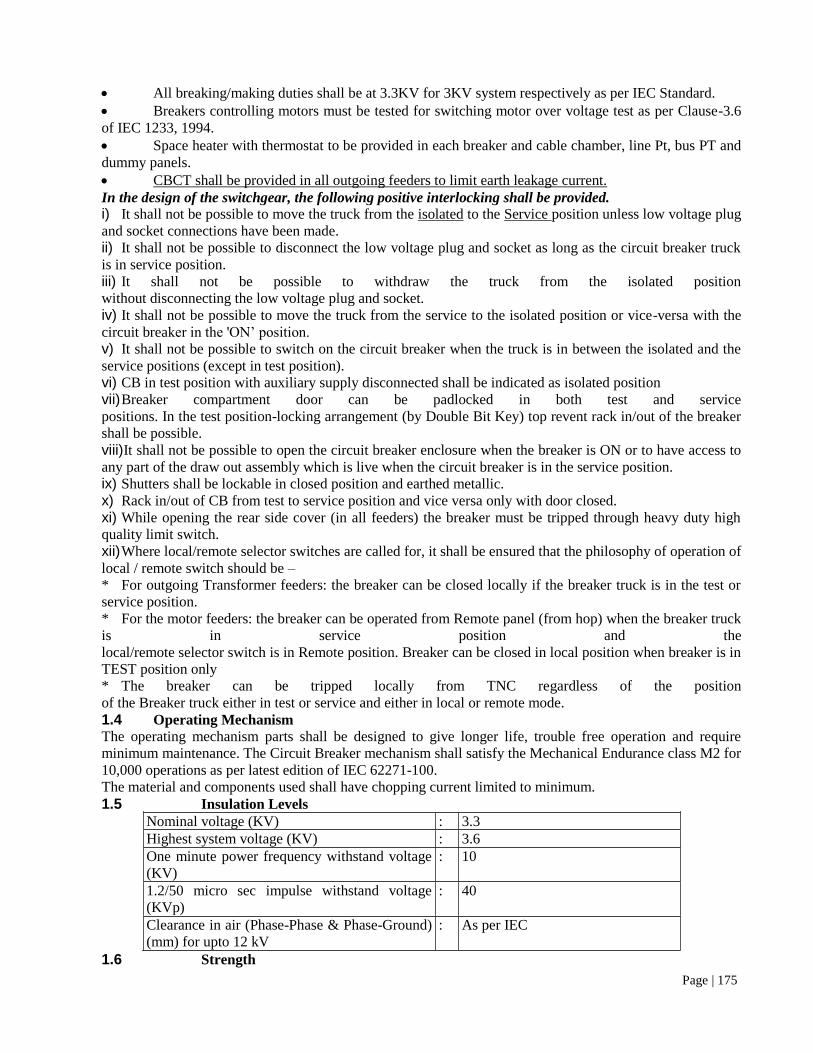
Page | 175
All breaking/making duties shall be at 3.3KV for 3KV system respectively as per IEC Standard.
Breakers controlling motors must be tested for switching motor over voltage test as per Clause-3.6
of IEC 1233, 1994.
Space heater with thermostat to be provided in each breaker and cable chamber, line Pt, bus PT and
dummy panels.
CBCT shall be provided in all outgoing feeders to limit earth leakage current.
In the design of the switchgear, the following positive interlocking shall be provided.
i) It shall not be possible to move the truck from the isolated to the Service position unless low voltage plug
and socket connections have been made.
ii) It shall not be possible to disconnect the low voltage plug and socket as long as the circuit breaker truck
is in service position.
iii) It shall not be possible to withdraw the truck from the isolated position
without disconnecting the low voltage plug and socket.
iv) It shall not be possible to move the truck from the service to the isolated position or vice-versa with the
circuit breaker in the 'ON’ position.
v) It shall not be possible to switch on the circuit breaker when the truck is in between the isolated and the
service positions (except in test position).
vi) CB in test position with auxiliary supply disconnected shall be indicated as isolated position
vii) Breaker compartment door can be padlocked in both test and service
positions. In the test position-locking arrangement (by Double Bit Key) top revent rack in/out of the breaker
shall be possible.
viii) It shall not be possible to open the circuit breaker enclosure when the breaker is ON or to have access to
any part of the draw out assembly which is live when the circuit breaker is in the service position.
ix) Shutters shall be lockable in closed position and earthed metallic.
x) Rack in/out of CB from test to service position and vice versa only with door closed.
xi) While opening the rear side cover (in all feeders) the breaker must be tripped through heavy duty high
quality limit switch.
xii) Where local/remote selector switches are called for, it shall be ensured that the philosophy of operation of
local / remote switch should be –
* For outgoing Transformer feeders: the breaker can be closed locally if the breaker truck is in the test or
service position.
* For the motor feeders: the breaker can be operated from Remote panel (from hop) when the breaker truck
is in service position and the
local/remote selector switch is in Remote position. Breaker can be closed in local position when breaker is in
TEST position only
* The breaker can be tripped locally from TNC regardless of the position
of the Breaker truck either in test or service and either in local or remote mode.
1.4 Operating Mechanism
The operating mechanism parts shall be designed to give longer life, trouble free operation and require
minimum maintenance. The Circuit Breaker mechanism shall satisfy the Mechanical Endurance class M2 for
10,000 operations as per latest edition of IEC 62271-100.
The material and components used shall have chopping current limited to minimum.
1.5 Insulation Levels
Nominal voltage (KV) : 3.3
Highest system voltage (KV) : 3.6
One minute power frequency withstand voltage
(KV)
: 10
1.2/50 micro sec impulse withstand voltage
(KVp)
: 40
Clearance in air (Phase-Phase & Phase-Ground)
(mm) for upto 12 kV
: As per IEC
1.6 Strength

Page | 176
Rated short time withstand current shall not be less than the system short circuit level specified for
the stipulated duration.
Rated peak withstand current shall not be less than 2.5 times the system short circuit level.
1.7 Auxiliary Circuits for Control & Protection
Control supply buses for AC and DC
Signalling supply
PT secondary voltage
All control & protection supply can be done through internal wiring instead of auxiliary bus.
1.8 Provision of Surge Suppressor
Breakers (VCB) that give rise to overvoltage surges due to current chopping phenomenon, surge suppressors
to be provided at the load side terminals of the breakers to limit the switching surges to value limited for as
per IEC. This shall be provided for all motor feeders after the breaker contacts before CT. Protection shall be
interconnected with respective breaker. Surge suppressor shall be metal oxide gapless type, 10kA discharge
current capacity.
1.9 Annunciation Schemes
Flag indications for all faults for which individual protective relays have been specified.
Warning signalling (as applicable) on individual panels:
a) All transformer warning/signaling conditions (group signal from corresponding transformer control
panel / substation.
b) Loss of trip circuit supply.
c) Earth fault.
d) Control supply failure.
e) PT fuse failure/MCB tripping.
f) Internal failure relay.
Emergency signalling for tripping of HT breakers on fault.
One common signal for warning and one signal for emergency from each panel to be wired to a
common annunciation panel of the switchboard, where specified.
Annunciators for warning and emergency signalling condition on individual panels of solid state
facia window type. Common audio signalling with Accept, Reset and Test push buttons for the switchboard
where common annunciation panel is not specified. Audio signalling to have distinct tones for warning and
emergency.
1.10 Bus Bar and Connections
Power buses of high conductivity electrolytic grade copper as per IS: 613-1984. The bus bars shall
be tinned coated/nickel coated/silver coated at joints as per IEC.
The bus bars shall be insulated with Raychem make insulating sleeves of full potential. Even that
part of isolating contacts which projects into the bus compartment shall be covered with an insulating sleeve.
Control and Auxiliary buses of electrolytic grade copper.
Anti-condensation measures by use of space heaters need not be provided in bus-bar chambers.
The continuous rating of the main horizontal bus not less than the rating of the incomer specified,
where not specified, the rating to be selected for at least 125% of the maximum demand of the switchboard
taking into account spare feeders.
The vertical bus rating
For incomer : Not less than that of horizontal bus
For outgoing : Not less than that of the outgoing breaker, irrespective of
relay setting.
Final operating temperature under continuous operation in enclosure limited as per permissible
values stipulated in IEC 62271-1 considering maximum ambient of 50degree Centigrade.
Both horizontal and vertical bus bars to be designed and supported to withstand the thermal and
dynamic stress corresponding to rated short time and peak withstand current specified.
Cross-section of main horizontal bus to be uniform throughout the switchboard and continuous in
one transport unit.

Page | 177
Bus bar arrangement as per IS:375.
Phase identification by colour in each panel or colour coded labels on each phase.
Bus bars (horizontal as well as vertical) shall be provided with heat shrinkable, non-tracking, low
absorption type sleeving conforming to international standards to the full potential.
Bus bar joints and tap off connections of bolted type with zinc dichromite high tensile steel bolts,
nuts and spring washers, fishplates with accessories at the end of a transport unit for site connections.
All the joints shall be provided with reusable & removable shrouds suitable for rated voltage of the
switchboards.
All busbar support insulators shall be of hydrophobic material having high impact and dielectric
strength with an anti-tracking contour.
Continuous path of Busbar chamber is acceptable. Seal-off bushings not
required inside HT switchboard.
Self-supporting busbars insulated to the full voltage level instead of support insulators can also be
provided. In that case, each compartment will be sealed from the adjacent cubicle and busbars will pass
through epoxy cast resin bushing.
Bus bar joints and tap off connections shall be of bolted type with zinc
dichromate high tensile stainless steel bolts (grade 8.8), nuts and spring
washers, fishplates with accessories at the end of a transport unit for site
connections.
1.11 Internal Control Wiring
Control wiring shall be carried out by 1100V grade PVC insulated, FRLS, single core multi
stranded copper wire of minimum cross section 1.5 sq. mm.
Multi-stranded flexible copper wire of min. 2.5sq. mm shall be used from CT secondary to relay
and shall have protection against heat & mechanical damage due to flash over. Use of heat proof sleeves and
rigid conduit shall be made to run the control wires from back to front.
All inter panel AC and DC control supply wiring shall be min. 4 sq mm flexible copper wire
Wiring and terminal arrangement for all panels shall be carried out as per approved scheme.
Flexible wires protected against mechanical damage for wiring to door mounted devices.
Wires identified at each end in accordance with schematic diagrams by interlocked type ferrules.
These shall be firmly located so that these do not move. Number of ferrules in place of interlocked type
ferrules can also be provided.
Color code for control wiring
AC – Black Earth wire – Green
DC – Light gray Trip circuit – Red
All connections external to a feeder, all the auxiliary contacts of the HV
breaker and at least 1 NO & 1 NC spare contacts of the relays shall be
brought to terminal blocks.
Interconnection between panels of adjacent shipping sections to be brought out to a separate
terminal block.
No bunch shall contain more than 12 wires.
Wiring shall not be joined or tied between the terminal points.
Control wires shall be run in earthed metallic flexible conduits when laid in HV bus chamber.
Not more than two connections shall be provided on any one terminal.
Heat proof arrangement for the passage of wiring in HT panel.
All tele-metering signals shall be wired to terminal strips.
1.12 External Terminations
1.12.1 Control Terminations
1.1kV grade multi-way open type terminal blocks of non-tracking moulded plastic complete with
insulated barriers, stud type terminals, washers, nuts and lock nuts and identification strips.

Page | 178
All terminals going out of the switch board shall be brought to a separate terminal board marked
"External Termination". These will be easily accessible.
External terminal block shall be provided in the relay chamber with proper clamping facilities for
cable dressing.
Disconnecting type terminal block for CT/PT and for AC/DC supply.
Control terminals shall be suitable to receive two numbers 2.5 sq. mm copper conductor.
20% spare terminals in each control terminal block. Terminal blocks in separate groups shall be
provided for transformer marshalling boxes, local push button stations,
Gland plate for control cables shall be of adequate size to accommodate and to facilitate glanding of
all the control cables coming from external equipment.
Terminal blocks shall be placed separately for internal looping and external looping.
1.12.2 Power Terminations
Suitable for accepting cable/bus trunking as specified.
Sufficient space and support arrangement inside each panel to accommodate HT cable termination
kits and sealing kits suitable for the size and number of XLPE cables. If it is with cable pan, then type test
reports shall be furnished. Gland plate in cable chamber shall have built in adjustable cable holding damp.
Where more than one cable has to be terminated per unit, the arrangement shall permit connection
and disconnection of cables separately without disturbing other cables.
Where specified the following cable termination accessories, suitable for the type, size and number
of cables to be terminated, to be supplied with switchboard.
Cable sockets with all HT terminals (sockets set at such an angle that cable tails can be brought up
for termination with minimum bending and setting).
HT cable termination and sealing kits.
Power cable termination facilities shall be designed to facilitate easy approach to CTs.
Double compression type brass cable glands and crimping type tinned heavy duty copper lugs for
HT, LT power and control cables.
Polycarbonate sheet between ph-ph and ph-E to be provided in all cable chambers.
All power cable terminations shall be covered with silicon rubber boot especially to be provided by
cable jointing kit manufacturer.
1.13 Protection and Measurement
1.13.1 Electrical Protection and Metering
Selection of protective scheme will be based mainly on reliability, sensitivity, selectivity. All main
protections shall be fast acting type in order to clear the faulty system from the healthy system in earliest
possible time to minimize damage to equipment and ensure continuity of power supply.
The details of major protections and metering for 3.3kV system are elaborated below. (Indicative only)
Sl. No. Feeder
Designation
Protection and Metering
Protection Metering
1. Bus Coupler
Over-Current and Earth
fault (50, 51, 51N, 50N)
Check Sync Relay (25).
High speed tripping relay,
close & trip circuit supervision
relay, aux relays, time delay as
required.
1 no. Multifunction
meter.
3 nos. Ammeter
2. Incomer
Over-Current and Earth
fault (50, 51, 51N, 50N).
Fuse failure protection of
line PT (97) (for alarm).
Check Sync Relay (25).
1 no. Multifunction
meter.
3 nos. Ammeter.
3 nos. Voltmeter with
voltmeter selector switch
for LINE PT.

Page | 179
Sl. No. Feeder
Designation
Protection and Metering
Protection Metering
High speed tripping relay,
close & trip circuit supervision
relay, aux relays, time delay as
required.
1 no P.F meter
1 no kWH meter
3. Transformer
Feeder
Over-Current and Earth
fault (50, 51, 51N, 50N).
High speed tripping relay,
close & trip circuit supervision
relay, aux relays, time delay as
required.
Provision of inter-trip from
downstream switchboard.
Earth leakage protection
with CBCT and EOR relay.
1 no. Multifunction
meter.
3 nos. Ammeter.
1 No. kWH Meter
4. Motor feeder
Motor protection relay
(99).
Time delayed U/V relay.
Over-Current and Earth
fault (50, 51, 51N, 50N).
High speed tripping relay,
close & trip circuit supervision
relay, aux relays, time delay as
required.
Provision for taking
RTD/BTD input
Earth leakage protection
with CBCT and EOR relay.
1 no. Multifunction
meter.
1 nos. Ammeter.
1 no. multifunction
Transducer to Remote
Ammeter.
Interposing CT for
remote ammeter
connection.
1 no kWH meter.
5. Bus
PT
HT Fuse on primary
MCB on secondary
Link (Drawout)
Under Voltage (27) with
timer
Fuse Failure (97) (for
alarm)
Neutral displacement relay
(60)
Over Voltage ( 59) with
timer
1 no. frequency meter
in BPT
3 nos. Voltmeter with
voltmeter selector switch.
1 no. Frequency meter
& PF meter
6. Line PT HT Fuse on primary
MCB on secondary
Link (Drawout)
Neutral Displacement relay
(60)
Note:-
Except MFM all the meters mentioned above shall be analogue type with 90 degree scale
1.13.2 Protective scheme requirements
Synchronization check relay/feature shall be provided in all the incomers and buscoupler feeders.

Page | 180
Synchronization check relay/ feature shall be provided in all the incomers and buscoupler feeders
Auxiliary relays, timers switches etc. required to make the scheme complete
shall be considered as part of the scope of work.
All CT-PT shall be suitable for the relay-meter requirement - lead burden
All CT-PT wires shall be brought to test terminal blocks before connecting to circuits. All
protective relays shall be provided with test block with jack for testing of relays.
The circuits of various protections (coming from other panels) shall be
connected to master trip relays through aux. relays (flag indicated). The
(MTR) Master Trip Relay shall be VAJH type or equivalent. For incomers & bus coupler feeders electrical
reset facility shall be provided in addition to the hand reset feature in MTR.
VAA type aux. relays shall be provided for each transformer fault.
Connection of the relay shall be through links to facilitate maintenance. All
external indication, alarm & trip contacts to a feeder shall be wired through
flagged aux. relays.
High end Relay ranges and scale of meters shall be finalized during drg. approval stage.
Contact arrangement, number of poles/ways in control/selector switches shall be as per the
requirement/approved scheme.
For control supply distribution, panel to panel separate set of terminal blocks
shall be provided at top of the panel. All items/accessories required for above in each panel and in incoming
panels shall be provided by the supplier.
All relays shall be hand/self-reset type with flag indication. NO/NC contacts
for relays shall be as per the requirement of approved protection,
annunciation & interlock schemes. Wherever required supplier shall provide
aux. relays for contact multiplication.
Trip Circuit supervision features can be a part of the numerical relay or if
provided separately through a relay shall be self-reset type with flag (hand
reset). Close Circuit supervision shall be through a separate relay which shall be self-reset type with flag
(hand reset). Close circuit supervision can also be a part of the numerical relay (NR) if the features are
available in NR.
Annunciation facia shall be mounted on each panel / separate switchgear panel and details shall be
finalized during drawing approval stage.
Centre line of switches, lamps, meters shall be matched to give uniform
Appearance and mounting height of switches shall be between 1.1 to 1.8 m.
Intelligent Electronic Devices (IEDs) shall be installed in the 3.3KV switchgear panels for control,
measurement and protection. The IED shall measure voltage, current, active power, reactive power, power
factor, energy, etc having minimum accuracy of 1.0%. The energy readings shall be in non-volatile memory
and IED shall not use any battery back-up. Four quadrant energy measurement shall be considered for all HT
feeders.
Each feeder shall have master trip relay and close/trip coil supervision relay.
Aux. Relays to be considered as per scheme requirement.
Relays shall be mounted on the HT switchboard itself unless otherwise
specified.
All protection trip from 415V switchboard to HT switchboard of various
substations shall be hardware wired.
Local /Remote selector switches, Trip selector switches, close permissive
switches, TNC Switches, Synchro Switches, Auto/Manual selector switches,
Emergency pushbuttons etc shall be provided in the panels as required to
fulfill the control logics.
Beside multifunction meter, Analog voltmeters, Analog frequency meters and Analog ammeters
shall be provided in all the incomers and interconnector feeders.
Analog Ammeters shall be provided in all the outgoing feeders.

Page | 181
1.13.3 Specification for MFM:
Provision of individual multi-functional metering system for all incoming and outgoing line
Meters should be capable to measure the following parameters
KWH, KVArH, KVAH ((import and export).
Meter should be capable to display the instantaneous parameters like voltage, current, PF,
Frequency, Inst. Load etc.
Meter should record data in its memory with a retention time of at least 10 years for parameters like
Active Energy, Apparent Energy, Av. Voltage, Av. Current, PF which can be viewed upon downloading
through CMRI in tabular as well as graphical view for at least 35 days.
Meter should be capable to record the Maximum demand on 15/30 mins integration period.
Meter should have a Four Line seven-digit LCD display with quadrant identification and power
level indication.
Meter should be capable of reading the Total Harmonic Distortion for current, voltage and power.
Meter should record the True RMS Value
Meter should be of Accuracy Class 0.2S
Compliance to IS 14697, IEC 62053-22
Meter should be of site/field configurable 3P3W/4W and CTR and PTR type.
Meter should record the Maximum demand for an IP of 15/30 mins
Meter should be capable to provide whole day data / Midnight snapshots for energy parameters
upon downloading
Meter should have MODBUS communication via RS 485 for online application
Meter should be have a Calibration LED for periodic site accuracy testing
Meter should have the setup page password protected so that it can be secured after installation.
1.14 Current Transformer (Panel Mounted)
Separate cores shall be used for, over current protection and measurement
purposes. CT's on incomer side shall be mounted in the bus before incomer
breaker and CT's for outgoing feeder shall be put after the breaker.
Short time thermal and dynamic ratings and insulation level of CT's shall be
similar to rating of associated breaker.
Short time ratings and insulation level of CT’s shall preferably be similar to rating of associated
breaker. However same may be different, based on various CT parameters for 3.3kV, SCR shall be 25KA for
1 sec for CT ratio of 250A & below and above 250A, SCR shall be 25KA for 3Sec. (preferably)
CT ratios specified are provisional. Where outputs and accuracy are not
specified, these shall be such as may be required by the circuits in which they are used. Generally the
protection CTs and metering CTs shall have 5P20 and 1 class respectively.
All CTs depending upon primary current rating shall be non-hygroscopic
epoxy cast resin insulated & bar primary type. CT may be wound primary up
to 250A. There should not be any air gap between primary and secondary of
CT to avoid failure due to partial discharge between primary and secondary.
CT's shall have shorting link on secondary side to facilitate insertion of
meters on secondary side without opening CT circuits.
Indicative CT ratios for incomer shall be1200/1 and Outgoing feedrs shall be 100/1A.
All CTs shall have class F insulation.
ICT for 5VA burden shall be provided for all motor feeders for 3.3KV system for the purpose of
remote metering.
1.15 Potential Transformers
Shall be cast resin insulated type mounted on withdrawable truck and
accessible from front end and shall be withdrawable without affecting power circuit.
PTs shall have fuses on high voltage side and MCBs on low voltage sides.

Page | 182
Low voltage star winding shall have all three phase and neutral connections brought out to terminals
and one phase shall be earthed.
Insulation levels shall be similar to rating of associated board.
Accuracy class shall be 0.5/3P.
VA burden shall be selected based on meters and relays connected with the PT from the following
standard values: 100VA, 200VA
The PT earth fault factor shall be as per table 2 of 1S-3156, Part-I, 1992.
All PTs shall have class F insulation.
For CTs and PTs: switch gear manufacturer’s own make can be acceptable however they must have
the in house manufacturing facility (casting and winding), testing facility and should have type tested design.
1.16 Relays
All protection relays shall be microprocessor based numerical &
communicable type (IEC-61850 compliant) for connection to the proposed
SAS system.
All relays shall be flush mounted in dust proof cases and shall be mounted on front side of cubicle.
The numerical relays provided for HT feeders and shall have facility to filter
out inrush currents so that lower setting for short circuit protection could be
utilised.
All protective relays shall be draw-out type.
Major relays are as indicated in the specification.
Master trip relay shall be hand reset and shall have 6NO and 6NC contacts
in addition to those required by the protection/control scheme.
All timers and Aux. relays shall have flag indicators & protection relays shall have LED indication
to indicate operation of the relay.
Relay ranges, exact type, number of aux. relays, timers shall be finalized
during drawing approval stage.
All instantaneous / IDMT current protection relays shall be of 3 pole type.
In HT switchboard two nos. bus PT's, with U/V relays neutral displacement
relays, timer etc. to be provided.
No plug-in type relays shall be used.
Feeder Management Relay (FMR)
Each feeder shall be provided with FMR which shall perform complete
control, protection and monitoring of that particular feeder.
Following digital signals shall be provided in FMR:
1) CB ON
2) CB OFF
3) Master Trip Operated
4) TC Healthy
5) Closing ckt healthy
6) CB Service
7) CB Test
8) Spring Charged
9) Local/Remote
10) DC Fail
11) All Transformer Alarm & Trip Signals (as applicable)
12) Cable side earthed (As applicable to a feeder)
13) Bus earthed (as applicable to a feeder)
14) Any other signal as listed in the Automation writeup.
The FM Relay shall be so selected that all protective functions configured on
the relays shall be displayed on the SAS through IEC-61850 communication
protocol.

Page | 183
All the necessary control & Interlock logic for that particular feeder shall be
built within the relay through graphic means with CFC.
Shall have inbuilt O/P contacts rated for direct connection to trip & close coil.
Shall have self diagnostic features with watchdog output.
Shall have I,V, P,Q, Cosɸ and energy measurement capabilities
Shall have graphical display unit.
20% spare I/O shall be available after complete engineering for future use.
1.17 Salient Specification points for Numerical relays:
Relay shall have Large Graphical display with dynamic mimic
Relay shall have minimum 8 freely configurable LEDs apart from fixed LEDS for relay ready/IRF,
protection start & protection trip.
Relay shall have Front port for local one to one communication and Rear RJ45 Port for remote
communication on native IEC61850 protocol.
Relay shall have 1000 + event records and 25 fault records with date and time.
Relay shall have WEB HMI feature to facilitate relay parameterization and fault record even in the
absence of dedicate relay software
Relay shall have minimum 12 Digital inputs (apart from those used for trip circuit supervision) and
10 output contacts + Dedicated contact for IRF.
Relay shall have dedicated Disturbance record facility apart from event & fault recording.
1.18 Indicating Instruments
All indicating instruments shall conform to IS: 1248-1983 and IS - 2419-1979.
Shall be capable of withstanding system fault current taking account CT saturation.
Shall be back connected.
Shall be located in the upper part of the panel.
Shall have 144 sq. mm square flush case, non-reflecting type, clearly divided and indelibly marked
scales, sharply out lined pointers and zero adjusting device.
The minimum scale reading shall not be more than 10%. Maximum reading shall be 15% full load
for transformers panels.
Each voltmeter shall be calibrated with coil hot. The scale shall be open between 60% to 125% of
normal volts and shall be suppressed below 60% of normal volts.
Class of accuracy shall be 0.5 or better.
The full load reading of each ammeter shall occur at the most pen part of the scale the minimum
scale reading shall not be more than 10%. Maximum reading shall be 15% full load for transformer panels
and 600% full load for motor panels.
1.19 Annunciation
The annunciator shall be microprocessor based, facia window type.
Hooter and bell for trip and alarm indication respectively.
Shall be suitable to work on DC supply as specified.
Test, accept and reset facilities (with push button) shall be provided on each panel.
Suitable audio - visual indication shall be provided on DC failure. Audio alarm with reset facility
shall be provided. Visual indication shall be panel- wise.
Spare annunciation points shall be wired upto terminal blocks. 20% spare fascias shall be provided.
Each point shall have two bunch LEDs in parallel.
All trip points facia shall have red color and non trip points white color.
The cover plate of facia shall be flush with panel.
Shall be capable to receive simultaneous signals.
Shall be capable to receive signal during testing mode.
Bidder shall ensure the non-presence of spurious signals due to influence of external
electromagnetic / electrostatic interference on the annunciation wiring and switching disturbances from
neighboring circuits within panels.

Page | 184
All interconnections, bell hooter, buzzer, alarm facility, push button etc. required to achieve
complete function of above scheme.
Sequence shall be as follows:
VISUAL AUDIO
ON OCCURRING OF FAULT LAMP FLASHING ON
ON ACCEPTING LAMP STEADY ON OFF
ON RESET (Fault Cleared) OFF OFF
ON TEST LMAP FLASHING ON
Annunciation facia (minimum 12 windows) shall be mounted on each outgoing switchgear panel. A
common alarm & annunciation facilities for control AC and control DC system with necessary flashers,
hooters, bells as required shall be provided in the switchboard. However, details shall be finalized during
drawing approval stage.
Bus coupler, Incomer and tie shall have minimum 16-window fascia.
20% spare window shall be available in each annuciator for future use.
Warning and emergency points shall be as per the list approved during detail engineering stage. In
general, all tripping points and alarm points shall be annunciated.
1.20 Control Supply
Control supply buses shall run throughout the switchgear.
Two DC feeders shall be taken in each board controlled by MCB’s.
In each panel for controlling of its DC supply MCB (DC duty) shall be used. DC auto changeover
and manual changeover facility shall be provided. Failure of each DC supply shall be monitored in the
switchboard as well as at remote.
240V AC supply shall be taken from a station aux. board.
Each section shall have separate feed with automatic changeover scheme.
Each panel shall have one MCB for controlling its AC supply.
Sub circuits shall be protected with HRC fuses in each panel for indication lamps, closing and
tripping circuits.
1.21 Earthing Devices
Separate earthing truck shall be provided to facilitate earthing of busbars and any feeder circuit.
Earthing truck shall have PT and alarm provision. (Separate trucks shall be provided for feeder and
bus earthing through bus PT panel in each switchboard). 1 no. earthing truck for feeder earthing and 1 no. for
busbar earthing shall be provided for each board. It shall not be possible to use bus earthing truck for feeder
earthing and vice-versa.
Rating of earthing device shall be in line with associated board.
Interlock provision shall be there so that incomer cannot be closed if bus earthing device is
connected.
1.22 Indicating Lamps
LED cluster type with OVGP (over voltage glow protection).
LEDs used shall be of the colour of the lamp.
Color shall be as follows;
TYPE OF LAMP : LED COLOUR
ON : RED
OFF : GREEN
AUTOTRIP : AMBER
TRIP CKT. HEALTHY : WHITE
SPRING CHARGED : BLUE
1.23 Control and Selector Switches
Control switches for circuit breaker ON/OFF control-3 position spring return to neutral with lost
motion device and pistol grip handle.

Page | 185
Other control and selector switches - stay put type with wing type knobs.
Voltmeter selector switches – 7 positions as required.
Colour : Black
Contact Rating :
Continuous 10 amps
AC 11 4 amps, 240V
DC 11 0.5A, 30V, L/R - 40 ms
1.24 Push Buttons
Contact Rating :
Continuous 10 amps
AC 11 4 amps, 240V
DC 11 0.5A, 30V, L/R - 40 ms
Colour :
ACCEPT BLUE
RESET BLACK
TEST YELLOW
1.25 Protective Earthing
Continuous earth bus of minimum size as per IEC 62271-200, Cl 5.3.2 made
of copper, designed to carry the peak short circuit and short time fault current
as specified.
Provided at the bottom extending throughout the length of the board,
bolted/brazed to the frame work of each panel with an earthing terminal at
each end for terminal at each end for terminating external earth conductor.
All non-current carrying metal work (including metallic cases of instruments
and other panel mounted components effectively) bonded to the earth bus.
Hinged doors earthed through flexible earthing braid.
Looping of earth connection resulting in loss of earth connection to other
devices when the loop is broken not permitted.
Withdrawable units provided with self aligning, spring loaded copper
scrapping earth contacts of make before/break after type, ensuring earth
continuity from service to the test position.
For cable earthing or bus bar earthing, earthing truck shall be provided. The
earthing truck shall be of specified making capacity with annunciation,
indication & interlock scheme. Alternatively front operated mechanically
interlocked earthing switch with specified making capacity shall be provided.
Earthing truck shall be provided with single phase PT.
1.26 Test and Maintenance Equipment
Each board shall be supplied with following items;
2 set of test plugs.
2 common transport trolley for interchanging withdrawable units, height of the trolley lifting arm
adjustable for raising / lowering the units. (In case of cassette mounted breakers)
Any other special purpose tools for maintenance.
2 Movable step ladder.
1.27 Constructional Features
001 Mechanical Design
Sheet steel clad, compartmentalized, floor mounted, free standing design. The panel shall uniform
depth.

Page | 186
Minimum CRCA sheet steel thickness shall be 2mm Gland plate shall be min 3mm thick.
Doors shall be provided with lock and key arrangement
Degree of protection shall be IP4X or better.
Assembled on base channel of structural steel of minimum 40 mm height
painted black.
Operating height shall be between 450 to 1800 mm. Switchboard height not
to exceed 2500 mm.
Earthed metallic barriers between compartments and between vertical
sections.
Zinc bichromated and passivated hardwares.
All supporting insulators in the bus chamber and bus duct shall be easily
accessible with detachable covers for easy replacements.
HT panel gland-plate shall be split type.
The shutter plate of HT cubicle shall be of insulated material/earthed metallic.
Removable lifting arrangement for each transport unit. The lifting
arrangement can be through sling from the bottom of the panel.
Lockable front doors with concealed hinges with the door not forming part of
the draw-out truck.
Panel door shall have provision of additional knock-out suitable for addition
of relay at a later date.
Panels shall be extendable on both sides.
Removable sheet steel covers shall be provided at rear. Alternatively, rear
covers shall be of bolted construction and made up of Alu-Zinc sheet.
Separate back covers with handles shall be provided for bus chamber & cable chamber.
Independent explosion vent for each HT compartment.
Explosion vent of resettable type may or may not be provided for each
compartment e.g. the CB chamber, cable chamber & bus chamber.
Control cables entry shall be from front side.
CTs shall be located in such a way that that they are easily accessible.
Panel door switch shall be provided for illumination inside the panel.
All live parts shall be insulated by Raychem HT sleeves, supported by suitably designed
insulators. Proper insulation of bus bars, upper and lower contacts of breakers and sealing of opening of
bushings shall be provided to eliminate accidental contacts.
Fire proof sealing shall be provided below the HT panels.
Screw wire mesh in the power cable chamber of all the feeder is to be
provided. Wire mesh will be provided in the CT compartment.
Separate slotted channel shall be provided in the cable chamber for clamping
the cable.
The manufacturer must have inhouse CNC fabrication facility. However,
CNC bending and electrostatic powder coating with paint thickness minimum 50 microns can be done at
vender's premises under close supervision of the manufacturer only. Fabrication of cubicle and assembly
outsourcing is not acceptable.
Transparent window need not be provided both front and back to inspect
earthing switch contact since earthing truck is to be used for earthing of
panels.
Panels will be made of CRCA sheet steel/Alluzinc
material, which is corrosion proof. The sheet steel is coated with unique
silvery spangle composed of AI (55%) Zinc (43%) and silicon (1.6%) for
perfect harmony with steel. Alluzinc sheet thickness shall be 2.0 mm.
However front doors and end covers are made of CRCA sheet thickness 2 mm with special re inforcement.

Page | 187
Switchgear panels will be made up of CRCA sheet steel/Alluzinc materials which do not require
painting. However, front doors shall be of CRCA sheet. Hence we shall provide painting on front doors only.
Surface treatment & painting shall be done at our vendors premises.
002 Labels
Switchboard designation nameplate at the center of the board with letters not
less than 25 mm high.
Panel designation number on each panel, both in front and rear
Inscription plate for each feeder on the door
Door front mounted devices to have labels directly below them
Labels made on non-rusting metal or 3 ply lamicoid with engraved inscription of white letters
(minimum 3 mm high) on black background.
Label designation and size of lettering subject to approval.
Bus side and cable side shutters labeled for identification.
003 Surface Treatment
All metal parts of the panel to undergo surface treatment that includes de-rusting, cleaning, chemically
degreasing, pickling in acid, cold rinsing, phosphating and passivating followed by spraying with two coats
of zinc oxide primer and baking in oven.
Panel interior base plate Off white shade
Exterior & interior Epoxy based RAL-7032
1.28 Technical particulars and design parameters
Sl. No. PARTICULARS 3.3KV Switchboard
1. Type VCB with stored spring mechanism
2. Service Indoor
3. Enclosure IP4X or better
4. Nominal System Voltage (KV) 3.3
5. Highest System Voltage 3.6
6. No. of phases and frequency 3ph. 50 Hz
7. Busbar material Electrolytic grade copper as per
IS:613:1984
8. Bus Colour code RYB
9. System Earthing Non-Effectively Earthed
10. Circuit Breaker Rating
A) Continuous Current Rating at
45-50°C 1250A
B) Short Circuit Rating 25KA for 3 Sec.
11. Busbar Rating 1250A
12. Power Frequency Withstand voltage 10KV for 1 minute
13 Impulse withstand voltage (1.2/50
microsecond )
40 KV
14 Control Voltage 30 VDC
15 Spring charge motor voltage 240 V AC
16 CT Ratio Secondary Current 5A
17. BPT ratio - STAR / STAR/ STAR Primary :(3.3/3) KV
18. LPT ratio - STAR / STAR/ STAR
Open Delta Primary :(3.3/3) KV
Secondary : (0.11/3) KV

Page | 188
19 Aux. Contacts 6 NO + 6 NC
Any additional contacts, If required
shall be obtained through contact
multiplication by contactors / relays.
20. Termination
21 Incomers XLPE FRLS Al Cables
22 Outgoings XLPE FRLS Al Cables
23 Joints And Isolating contacts Silver Plated
24 End Temperature of all current
carrying parts including breaker
Shall be governed by IEC 694.
Temperatures rise will be calculated
with ambient temperature of 50°C and
considering an in-panel rating.
1.29 Type Test certificates:
a) Following Type test certificates relevant to HT switchgear as per IEC: 62271-100 will be furnished
during DE:-
1. Test Duties 9T10 to T100a, t100s).
2. Single Earth Fault (SEF).
3. Double earth Fault (DEF).
4. Capacitor Duty.
5. Cable Charging Duty.
6. Impulse Test.
7. Temperature Rise Test
Short Time Rating for 3 sec equivalent to full Fault Current.
1.30 Interlocking Scheme(between incomer and buscoupler)
A) Momentary Paralleling
Manual changeover from one incomer to another with momentary paralleling of the two supplies after
checking through synchro check relay (located at Bus Coupler panel).
Manual live changeover facility shall be provided for the switchgear. When planned outage of one of the
normal incoming supplies is required, the respective incomers shall be tripped automatically after the bus
coupler breaker is closed manually. For this purpose, a selection shall be provided through a selector
switch. Depending on the selection made, incomer to bus coupler– I or to bus section–II shall be tripped
once bus coupler breaker is closed manually, thus maintaining continuity of supply.
A timer (with a time delay on pick up of 0.5. - 5 sec.) shall be provided for annunciation if the running
breaker fail to trip within a preset time, (i.e. if the two sources remain paralleled for more than a preset time).
When the normal supply is to be brought back into operation, the incomer breaker shall be closed manually
whereupon the bus coupler shall trip automatically.
B) Manual dead bus closing of either bus-coupler or Incommer1 or 2 shall be possible after an
intentional manual trip/outage (due to under voltage) of any one incomer. However, restoration to normal
shall be manual only.
Latest breaker tripping provision shall be included in the change over scheme in addition to annunciation.
1.31 COMMISSIONING ASSITANCE
Bidder shall provide testing & commissioning assistance at HCL Chapri, Sidheswar for four (4) working
days of one (1) person during testing & commissioning. Bidder shall also arrange his own transport, local
transport, accommodation etc during assistance at HCL Chapri.
04.13.2.16 AC DISTRIBUTION BOARD (ACDB and DCDB)
Board shall be single front, metal clad, front matched, dust and vermin proof, fully
compartmentalised and extensible on both sides, IP51 type enclosure.
Board shall have base channel of size ISMC75.

Page | 189
Board shall have isolated busbar chamber for main busbar at the top, running through out the length
of the board. Chamber shall have removable cover.
Cable alley shall have sufficient space for aluminum power cables and bottom cable chamber shall
be left free completely isolated from the vertical bubars.
Busbars shall have same cross section through out the length. Rating of the neutral bus bar shall be
50% of the main bus bar. Earth bus bar shall run in bottom chamber through out the length of the panel.
Board shall have Moulded Case Circuit Breaker (MCCB) triple pole, air break type with
independent manual quick make and break type. MCCB shall be capable of breaking rated current at 0.3 pf
at the rated voltage. MCCB shall withstand the fault current envisaged for 415V system.
Earth leakage protection with CBCT and separate EOR relay in al outgoing feeders.
ACDB shall be painted as per shade 221 of IS-5 or RAL equivalent
All feeders shall have ON/OFF lamps and 96 sq mm size ammeter.
Incomer & Bus-coupler shall have manual operated MCCBs with Microprocessor based o/c, short
circuit, earth fault & shunt trip releases and out going shall be MCCB/MCBs.
Mechanical interlock shall be provided in ACDB.
Constructional features of ACDB shall be in line with DCDB.
Construction Features
The battery chargers and the DC distribution board (including alarm annunciation) may be
integrated into one switchboard or separate boards may be provided.
Switchboard shall be floor mounting type sheet steel enclosed with degree of protection IP 52 or
better.
Sheet steel used shall be CRCA of minimum 2 mm thickness except for doors and covers for which
1.6 mm thick shall be used.
Cable entry shall be from bottom, removable gland plates shall be provided.
All components shall be mounted above 450 mm and below 1850 mm from the floor level.
Wiring and Terminations
All power wiring shall be done through single core PVC insulated copper wires/buses.
All control wiring shall be done through single core, PVC insulated copper wire of 2.5 sq. mm
All connections external to the panel/switch board shall be terminated in suitable terminal blocks.
Inter panel wiring shall be only between terminal blocks.
Each wire shall be identified by ferrules corresponding to the schematic diagram.
Testing Of Equipment
Tests of all equipment shall be conducted as per latest ISS/IPSS. Tests shall also confirm to
International Standards IEC/VDE/DIN/BS (in case corresponding test are not mentioned in ISS/IPSS).
Manufacture test certificate for major bought out components shall be submitted during inspection.
04.13.2.17 BATTERY, BATTERY CHARGER AND DC DISTRIBUTION BOARD
1.0 Scope and Mode of Operation
The system shall include:
One Battery system comprising with
- DC battery set.
- Identical (Dual) automatic float-cum-boost chargers and one no. double bus DC distribution
switchgear.
Normally one of the chargers shall supply the DC load and also keep the battery under float charge. On
failure of supply from charger, the battery shall take over without any interruption. The other charger shall
be 'off'.
When the battery requires boost charging, one charger will operate on boost charge mode, while the second
charger will supply the DC load on float mode. The battery's +ve shall be connected to the boost charger

Page | 190
while an intermediate tap shall be connected to the float charger (through a blocking diode) to take over the
load in the event of supply failure from charger.
The DC distribution board shall feed the power from the charger/battery to the various consumers as
required.
1.1 BATTERY , BATTERY CHARGER & DCDB
1.1.1 TECHNICAL SPECIFICATION
1.1.1.1 Scope and Mode of Operation
i)The scope includes :
Battery set (Sealed Plante cell valve regulated lead acid).
Identical dual automatic float-cum-boost charger for the above battery set.
DCDB
ii)Normally the chargers connected to the battery shall supply the DC load and also keep the battery under float
charge. On failure of supply from charger, the battery shall be taken over without any interruption.
iii)When the battery requires boost charging, the charger will operate on boost charge mode while the second
charger will supply the DC load on float mode through changeover arrangement.
iv)Battery sizing shall be based on the 6 hours backup time.
1.1.1.2 Battery and Accessories
i)Nominal voltage shall be as indicated in technical specification for design. The no. of cells shall be chosen
accordingly. Battery cell shall be maintenance free. The type of battery shall be as per technical specification.
ii)Each cell shall be rated as :
Parameters / Type Plante
Nominal Voltage (V) 2
Float charging voltage (V) 2-2.3
Boost charging voltage (V) 2-2.75
Voltage at the end of 10 hours discharge (V) 1.85
iii)200 Ampere hour capacity shall be provided for Design of 10 hours discharge rate with final voltage per cell of
1.85 V for Plante type.
iv)Bidder shall select number of cells based on following:
System Voltage 30V
Maximum voltage during float operation 33V
v)For Lead Acid Battery (Plante type) :
For faster discharge rate, the permissible continuous load with final discharge voltage 1.85 V per cell shall be:
Discharge Time Ampere Hour capacity in percentage of rated 10 hour capacity
10 hours 100%
5 hours 67%
3 hours 60%
1 hour 33%
vi)Standards to be followed: Plante Battery confirming to IS:1652
vii)Accessories to be supplied along with each battery set are :
Cell testing voltmeter 3-0-3 volts with least count of 0.01V, complete with leads.
Copper cell connectors
Spanner for cells, Torque wrench, Acid resistant, gloves and Protective apron.
Bridging clamps for cutting out individual cells in the event of defect.
First aid box.
Cell Booster for each set
For Plante type only:

Page | 191
Teak wood stand finished with 3 coats of black anti sulphuric acid paint complete with cell number
plates and fixing nails. Suitable for double row single tier arrangement/as per layout.
Acid for first fill and 10% spare capacity
Mercury in glass clinical thermometer for 0-1000C temperature measurement range
Syringe type hydrometer
Float type level indicator
2 liter jug and acid resistant funnel
viii)Container :
Shall be high quality transparent plastic boxes with top lids, vent plugs and suitable electrolyte level
indicator.
ix)Cell cover / lids:
Shall be sealed type of glass, plastic or ebonite material and provided with vent plugs.
x)Separator:
Separators shall be of synthetic material as per IS 6071
xi)Connectors, nuts & bolts:
Connectors shall be lead to withstand corrosion due to H2SO4 at very high rate of charge/discharge. Intercell
connectors should be protected with heat shrinkable silicon sleeves.
Nuts / bolts for connecting cells shall be of Copper, Brass or Stainless steel. Copper & Brass nuts/bolts
should be lead coated.
xii)Battery stand:
All batteries shall be mounted in galvanised steel structural rack for Lead acid Plante type. It shall be painted
with acid resistant paint. Suitable insulation shall be provided between stand & ground to avoid grounding of
stand.
xiii)Venting device
This shall be antisplash type with more than one exit holes and shall allow gases to escape freely but shall
effectively prevent acid particles/spray from coming out. For 120AH and above, two vent holes shall be
provided
xiv)Electrolyte
Sulphuric Acid and water used for preparation and maintenance of electrolyte shall confirm to IS 266 and IS
1069 respectively.
xv)Electrolyte level indicator
Suitable indicator showing lower and upper limits shall be fitted to facilitate checking of electrolyte level in
opaque containers. Material shall be acid proof and shall not detoriate during service.
1.2 Battery Chargers
1.2.1 General Requirement
i)Identical dual automatic float cum boost chargers for battery comprising of :
MCCB, line contactor and overload relay on the ac side for each charger.
3 phase full wave full controlled thyristorised rectifier bridge complete with free wheeling diode and
blocking diode. The thyristors and diodes shall have high speed fuses for protection against short circuits.
Necessary snubbers for hole storage effect shall also be provided.
Rectifier transformer shall be dry type double wound with copper conductor and class `B’ insulation
Filter circuit at the output
MCCB on DC side
Control and protection circuits as per requirement
ii)In float mode, the charger operates with a constant voltage controller and the output voltage of the charger shall
be maintained within + 1% of the set voltage for + full range variation in input AC voltage (as per General
specification)
or
0 – 100% load variation
or
both occurring simultaneously
The output voltage required can be set externally through potentiometers in the range 90-120% steplessly.

Page | 192
iii)In boost mode, the charger shall be suitable to operate in a constant current as well as constant voltage mode
with manual selector arrangement, controller suitable for two-rate charging. The charging current shall be
externally adjustable from 20 to 100% steplessly.
iv)Provision of charging with manual control of output voltage shall also be provided.
v)Electronic current limiter, adjustable between 85-105% of rated current shall be provided.
vi)During boost charging, the charger shall be cut-off as soon as over voltage occurs.
vii)Ripple content in the charger’s output voltage shall not exceed 0.5% in float mode and 3% in boost mode.
viii)The charger efficiency shall be minimum 80% under all operating conditions.
ix)The supply to the charger will be at Three phase LT voltage and frequency with their variations, as mentioned in
General specification
x)The charger shall have voltage rating corresponding to the battery. However, the charger rating shall be chosen
to charge the battery from 1.85 volts per cell (For Lead Acid & Plante Only) to fully charged condition in 10
hours.
xi)The changeover of battery from float to boost condition and vice versa shall be automatic. However, provision
for manual changeover shall also be provided.
xii)PCBs used shall be made up of glass epoxy material. PCBs shall include LED indication and test connection in
front to facilitate fault diagnostic.
1.2.2 Relays
i)The following relays shall be provided :
AC input supply to charger failure
Earth fault
Float bus over and under voltage
Boost bus over voltage
Boost over current for each charger circuit
ii)All relays shall be in draw-out cases and with mechanical hand reset operation indicator.
1.2.3 Indicating lamps
i)The following LED indications shall be provided.
AC supply ON (for 3 phases separately) for each charger
DC supply ON for charger
Boost/float mode ON for charger
1.2.4 Metering
i)The following measurement shall be provided
AC input voltage and current of each charger (through voltmeter & ammeter with selector switches)
ii)DC output voltage and current of each charger
Battery charging/drain current of each charger with necessary shunt
Battery trickle charging current (through amplifier)
DC bus voltage (through selector switch) to measure between Positive to Earth, Negative to Earth &
positive to negative.
1.2.5 Alarm Annunciation
i)16 window static type annunciation shall be provided on charger panel for the following :
AC supply failure to charger
Battery earth fault (+ve & -ve 192eparately)
Float bus over/under voltage
Boost bus over voltage
Boost over current for each charger
Failure of thyristor/diodes for each charger
Failure of blocking diode
Input MCCB open for each charger
Battery MCCB open
Battery room exhaust fan OFF
D.C. Voltage Low

Page | 193
D.C. Voltage High
A.C. Input Under Voltage
ii)The annunciation system shall incorporate solid state facia window type annunciators. The sequence shall be :
iii)On incident of fault, a hooter will become ON and the corresponding window’s lamp will start flashing
iv)On pressing “Accept” button, hooter shall stop and lamp shall become steady
v)On pressing “Reset” button, the lamp will stay ON if the fault still persists or will go OFF if the fault has been
cleared.
vi)One repeat alarm point for all above annunciations shall be provided to facilitate annunciation of “Fault in
Charger” in control room.
vii)The power supply for the above annunciations shall be taken from the DC float bus.
viii)A separate annunciation scheme with an AC hooter shall be provided for DC supply failure. This annunciation
shall be fed from the AC supply. Reset shall be by a stay put push button.
1.2.6 Constructional Features of Charger
i)Charger shall be free standing, floor mounting type, sheet steel enclosed with degree of protection IP 42 or
better.
ii)Sheet steel used shall be of minimum 2 mm thickness except for doors and covers for which 1.6 mm thick cold
rolled sheets shall be used.
iii)Cable entry shall be from bottom, removable gland plates shall be provided.
iv)All components shall be mounted above 400 mm or below 1800 mm from the floor level.
v)Panels shall be painted in epoxy light grey colour as per shade 631 of IS: 5.
1.2.7 Wiring and Terminations
i)All power wiring shall be done through single core 1100V PVC insulated stranded copper wires / copper buses.
ii)All control wiring shall be done through single core, PVC insulated stranded copper wire of 2.5 sq. Mm
iii)All connections external to the panel/switch board shall be terminated in suitable terminal blocks. Inter panel
wiring shall be only between terminal blocks.
iv)Each wire shall be identified by ferrules corresponding to the schematic diagram.
1.3 Technical Particulars And Design Parameters
1.3.1 Battery Set
Sl. No. Particulars Design Parameters
1. Voltage 110 V
2. Rating Bidder to specify as per the substation load and with
MINIMUM 6 HR BACK-UP TIME
3. Type PLANTE
4. Nominal cell voltage 2.00 V
5. End cell voltage 1.85 V for Lead Acid & Plante type
6. Discharge rate C10
7. Ampere Hour Capacity 150AH
1.3.2 Dual float-cum-boost charger
Sl. No. Particulars Design Parameters
1. Input voltage and frequency Three phase LT AC supply as per General
specification
2. Voltage variation As per General specification
3. Frequency variation As per General specification
4. Charging voltage As per Technical specification
5. Incomer to charger MCCB
6. Incomer to Battery MCCB
7. Protection to thyristors Through high speed fuse
8. Ripple content
Float mode 0.5%
Boost mode 3.0%

Page | 194
Sl. No. Particulars Design Parameters
9. Charger efficiency 80% (Min)
10. Mode of operation As per Technical specification
11. Charger rating As per Technical specification
1.4 Testing Of Equipment
1.4.1 Testing
i) Tests of all equipment shall be conducted as per latest ISS/IPSS. Tests shall also confirm to
International Standards IEC/VDE/DIN/BS (in case corresponding test are not mentioned in ISS/IPSS).
ii) Manufacture test certificate for major bought out components shall be submitted during inspection.
1.5 DC Distribution Board
The DC distribution board shall have double busbar arrangement, viz. one set of the +ve and -ve
connected to charger-1 and another set of +ve and -ve bus connected to charger-2. It shall be possible to
connect the bus bars with either charger through selector switches.
DCDB shall be considered as independent floor mounted panel, not integrated with Battery Charger
Panel.
Indicating instruments shall be as per IS 1248, accuracy class 1.5, 96 x 96 mm size.
AC meters shall be taut band type, DC meters moving coil type.
DC meters shall be zero centre type where applicable.
1.6 Feeder Arrangement
Each outgoing circuit shall be connected to both the sets of bus bars through selector switch. It shall
be possible to connect each outgoing circuit to either set of bus bars. Each outgoing circuit shall have
MCCB. Incomer shall have AC/DC voltmeter and all outgoings shall have indicating lamps.
The quantities and rating of outgoing feeders are indicative only and shall be finalized during detailed
engineering.
1.7 Construction Features
The battery chargers and the DC distribution board (including alarm annunciation) may be
integrated into one switchboard or separate boards may be provided.
Switchboard shall be floor mounting type sheet steel enclosed with degree of protection IP 52 or
better.
Sheet steel used shall be CRCA of minimum 2 mm thickness except for doors and covers for which
1.6 mm thick shall be used.
Cable entry shall be from bottom, removable gland plates shall be provided.
All components shall be mounted above 450 mm and below 1850 mm from the floor level.
1.8 Wiring and Terminations
All power wiring shall be done through single core PVC insulated copper wires/buses.
All control wiring shall be done through single core, PVC insulated copper wire of 2.5 sq. mm
All connections external to the panel/switch board shall be terminated in suitable terminal blocks.
Inter panel wiring shall be only between terminal blocks.
Each wire shall be identified by ferrules corresponding to the schematic diagram.
1.9 COMMISSIONING ASSITANCE
Bidder shall provide testing & commissioning assistance at HCL Chapri, Sidheswar for four
(4) working days of one (1) person during testing & commissioning. Bidder shall also arrange his
own transport, local transport, accommodation etc during assistance at HCL Chapri.
04.13.2.18 HT POWER, LT POWER & CONTROL CABLES (FRLS TYPE).
i) 33kV(E) & 6.6kV (UE) HT XLPE POWER CABLE
Sl. No. Parameter Description
1.0 Voltage Grade 33 kV(E) & 6.6kV (UE)
2.0 Duty type Heavy duty
3.0 No. of cores 3 Cores

Page | 195
4.0 Reference standard IS:8130 – 1984
IS:5831 – 1984
IS:3975 - 1999
IS:1554 (Part-2) - 1988
IS: 3961 (Part-2) - 1967
IS:7098 (Part-2) - 1985I
IEC-60502
5.0 Conductor type Compact circular stranded (rm/V) copper conductor, with
extruded conductor shielding of semi conducting material.
Conductor construction as per IS 8130-1984.
6.0 Insulation type XLPE insulated, with insulation shielding over individual
cores, consisting of extruded semi conducting compound,
followed by lapped semi conducting material and copper
tape (non-magnetic) metallic screen, cores stranded
together with a holding tape provided with a common
covering of extruded inner sheath of type ST2 compound .
Manufacturing process shall be continuous vulcanized
triple extrusion process simultaneously applying a
thermosetting semiconductor screen, a thermosetting XLPE
insulation & thermosetting semiconducting core screen in
one operation with dry cured and dry cooling process.
7.0 Armour Galvanised round steel wire double armouring.
8.0 Outer sheath FRLS Type ST-2 compound as per IS 7098 Part-II, 1985,
as amended upto date.
Black in colour for 3core. Red , yellow & Blue for single
core
Suitable chemicals shall be added into the PVC compound
of the outer sheath to protect the cable against rodent and
termite attack.
9.0 Miscellaneous Copper screen shall be suitable to carry 1kA E/F current for
one second.
10.0 Temp. rise on continuous
load
90 deg.C
11.0 Oxygen index of outer
sheath material for XLPE
Cable
Shall not be less than 29 at 27 2 deg. C.
12.0 Temperature index Not below 250C.
13.0 Maximum conductor
withstand temperature
during short circuit.
250C
13.0 Smoke Density Rating Minimum average light transmission of 40 %
14.0 ACID Gas Generation Max. 20% by weight
15.0 Flammability Test As per IEC-332/IEEE-383
16.0 Fire Resistance Test As per IS 5831
ii) 1.1kV PVC LT POWER CABLE
Sl. No. Parameter Description
1.0 Voltage Grade 1.1 kV grade
2.0 Duty type Heavy duty
3.0 No. of cores For power supply to other panel 4 core (upto conductor size
of 50 sq.mm) or 3.5 core (for conductor size beyond 50

Page | 196
sq.mm) cables shall be used.
4.0 Reference standard IS:8130 – 1984
IS:5831 – 1984
IS:3975 – 1999
IS:1554 (Part-1) - 1988
IS: 3961 (Part-2) - 1967
IS:7098 (Part-1) - 1988
IEC-60502
5.0 Conductor type - Copper conductor.
- All power cables of size 10 sq.mm and above shall
have standard sector shaped (sm) or compact circular
stranded (rm/V) or circular stranded (rm) aluminium
conductors as applicable.
- The conductors shall be H2 or H4 grade.
- The solid conductor shall be class - 1 and the stranded
conductor shall be class - 2.
- The conductors shall be solid for conductor of
nominal area upto and including 6 sq. mm. and stranded
beyond 6 sq. mm. Conductors of nominal area less than 25
sq. mm. shall be circular or shaped. Cables with reduced
neutral conductor shall have sizes as per Table 1 of IS 1554
(Part-1) -1988.
6.0 Insulation type - PVC insulation.
- The insulation compound shall be conforming to IS:
7098 (Part-1) - 1988.
7.0 Inner sheath - For armoured / unarmoured cables a tough inner
sheath of heat resisting PVC compound (wrapped /
extruded as per size), Type ST2 as per IS 5831.
- Black in colour.
8.0 Armour Galvanised round steel wire double armouring.
9.0 Outer sheath - For armoured/unarmoured cables a tough outer sheath
of heat resisting PVC compound (Type ST2 as per IS
5831).
- Black in colour.
10.0 Temp. rise Shall be limited to 90 deg. C.
11.0 Core identification - Cable identification shall be provided by embossing
on the outer sheath the following:
Manufacturer’s name & trade mark
Voltage grade
Year of manufacture
Type of insulation
- R, Y, B for phases.
- Black for neutral (fourth core)
iii) 1.1kV PVC CONTROL CABLE
Sl. No. Parameter Description
1.0 Voltage Grade 1.1 kV grade
2.0 Duty type Heavy duty
3.0 No. of cores As per BOQ.
4.0 Reference standard IS:8130 – 1984
IS:5831 – 1984
IS:3975 - 1999

Page | 197
IS:1554 (Part-1) - 1988
IS: 3961(Part-2) - 1967
IEC-60502
5.0 Cross sectional area 2.5 sq.mm
6.0 Conductor type Annealed circular stranded copper conductor.
7.0 Insulation type PVC Type- C insulated
8.0 Inner and outer sheath - Type ST-2 PVC shall be used for inner sheath.
- Type ST-2 PVC shall be used for outer sheath.
- Both inner and outer sheath shall be extruded type upto
7 core and after 7 core inner sheath shall be wrapped.
9.0 Armour Galvanised round steel wire double armouring.
10.0 Core identification - Cable identification shall be provided by embossing
on the outer sheath the following:
Manufacturer’s name & trade mark
Voltage grade
Year of manufacture
Type of insulation
- Cores of the cables upto 5 cores shall be identified by
colouring of insulation.
- For cables having more than 5 cores, core
identification shall be done by numbering insulation of core
sequentially.
- All the numbers shall be of same colour, which shall
contrast with the colour of insulation.
- Numbers shall be written in figures and words both
- The numerals shall be legible and indelible.
- The numbers shall be repeated at regular intervals
along the core, consecutive numbers being inverted in
relation to each other.
- When number is a single numeral a dash shall be
blacked underneath.
- If the number consists of two numerals, these shall be
disposed one below the other and a dash placed below the
lower numeral.
- The spacing between consecutive numbers shall not
exceed 100 mm.
04.13.2.19 415 V POWER CONTROL CENTRES
LT Switchboard
Nominal system voltage 415 V
System earthing Neutral solidly earthed
Short time rating 50 KA for 1 Sec.
Making capacity 105 kA
Control supply 110V AC
Configuration As per IS
Colour code R Y B
Busbar rating As indicated in Schedule of
quantities
Enclosure IP-4X or better
Circuit Breakers
Symmetrical breaking current 50 kA

Page | 198
Making capacity 105 kA
Short time rating (for 1 second) 50 kA
Rating for Incomers and Buscouplers 1250 A / 2000 A
Rating for outgoings (ACBs) As indicated in Schedule of
quantities
Closing mechanism
Incomers & bus couplers Motor operated spring charged
stored energy type
Outgoing feeders Manual operated
Tripping mechanism Shunt trip
Control supply 240 AC
No. of auxiliary contacts 6 NO + 6 NC for future use
Termination
Incomer Armoured cable
Outgoing Armoured cable
Feeder Arrangement
Incomer
(Mounted in single tier arrangement)
Air circuit breakers
Outgoings
(Mounted in two/three tier arrangement for
ACB / MCCB respectively)
Air circuit breakers / MCCBs
Schedule of Components
Sl. No. Schedule of components equipment
specification
Type of Feeder
B/C Incomer Out going
ACB
Feeder
1.a 415V, 50 kA air circuit breaker with: 1 1 1
- independent manual spring charged
closing mechanism.
- shunt trip
- Mechanical ON/OFF indicator
2. Microprocessor based direct acting
O/C, S/C & EF release with timer
- - 1
3. Control switch ON/OFF with spring
return to neutral
1 1 1
4. Voltmeter with selector switch 1 1 -
5. Ammeter 1 1 1
6. Selector Switch for Ammeter 1 1 1
7. kWh meter - 1 1
8. PF meter - 1 -
9. Twin core current transformer class 1.0
for metering and 10P15 for protection
cores
3 3 3
10. Core balance current transformer 1 1 1
11. Triple pole inverse time over current
relay with 2 O/C element with 50-
200% setting range, and 1 E/F element
20-80% setting range type SPAJ140C
or equivalent.
1 1 -

Page | 199
Sl. No. Schedule of components equipment
specification
Type of Feeder
B/C Incomer Out going
ACB
Feeder
12. Inverse time over current relay type
SPAJ140C or equivalent, setting 20-
80% for back up earth fault protection.
- 1 -
13. ON/OFF/Trip on fault/Trip circuit
healthy lamps
3 4 4
14. Auxiliary relays flag indication for
winding temp. alarm and trip signals
- 6 -
15. Auto changeover scheme with under
voltage relay, PT etc.
As per Requirement
16. Set of CTs as per requirement 1 1 1
17. Set of relays, contactors, timers, etc.
for annunciation scheme
As per Requirement
18. Set of relays, contactors, timers for
auto changeover scheme
As per Requirement
19. Impulse switch for tripping upstream
breaker
- 1 -
20. Two position, two contacts stay put
switch with pistol grip handle for
closing permission of upstream kV
breaker
- 1 -
21. ON/OFF lamp indication of upstream
breaker
- 2 -
22. Inter tripping push button to trip the
upstream breaker
- 1 -
04.13.2.20 LIGHTING TRANSFORMER
Sl.No. Parameter Description
1.0 Type Dry Type
2.0 Power Rating 20 KVA or as described in
schedule of quantities
3.0 Primary Voltage 415 V
4.0 Secondary Voltage 120 V with mid point earthed
5.0 Connection Star – Delta
6.0 Tapping +/- 10% in steps of 2.5%
04.13.2.21 FLOOR MOUNTED MAIN LIGHTING DISTRIBUTION BOARD
A. General
1.0 Type - Metal clad .
- Non drawout type.
2.0 Construction - Modular construction .
- Fully compartmentalized with metal / insulating

Page | 200
material partition.
3.0 Enclosure class IP52
4.0 Type of execution
Single front.
5.0 Mounting - Floor mounting.
- Free standing with ISMC 75.
6.0 Installation Indoor.
B. Constructional Features :-
1.0 Sheet steel
Thickness - 2 mm for load bearing members.
- 1.6 mm for non load bearing members.
Material CRCA
2.0 Cable entry - Incomer :- Bottom cable entry.
- Outgoing :- Bottom cable entry.
3.0 Design - Separate bus alley and cable alley on opposite side
of the outgoing modules .
- All the components shall be accessible from front .
- Each module to have covering at the bottom.
4.0 Interlocking &
protection
- Module door interlocked with main power isolating
devices.
- Power circuit isolation device to have pad locking
in the OFF position with door closed.
5.0 Operating height - Minimum :- 300mm
- Maximum :- 1800 mm.
6.0 Gland plate Undrilled removable bottom gland plates
(3 mm thick)
7.0 Miscellaneous - Neosprene rubber gasket shall be provided for all
the doors , removable covers & between adjacent
covers .
- Lifting hooks for the panel .
- Doors shall have concealed hinges .
9.0 Earthing - Two separate earthing terminals will be provided.
- Bolted joints with tooth spring washers for good
earth continuity.
- Earth bus to run in all cable alley of the panel .
C. Busbars
(i) Main horizontal & vertical busbars
1.0 Arrangement
Three phase & neutral.
2.0 Material High conductivity electrolytic aluminium alloy
confirming to grade E91E as per IS-5082 –1981.
3.0 Phase Busbar
Rating
- Shall be able to carry continuously the connected
load (considering all derating factors) plus a 25%
margin .
- Max. current density shall be
- 1.0 A/sq.mm for Aluminium
- 1.5 A/sq.mm for Copper .
4.0 Neutral Busbar
Rating
50 % of phase busbar rating
5.0 Short circuit rating
50 KA for 1 sec.

Page | 201
6.0 Busbar
configuration
Red-yellow-blue from front to back or top to bottom
or left to right as viewed from front.
7.0 Max. temp. rise of
bus
Not to exceed 35 deg. C. above ambient of 50 deg.C.
8.0 Air clearance for
bare busbar
Phase to phase :- 25.4 mm (minimum)
Phase to earth :- 19.0 mm (minimum)
9.0 Vertical busbar Rear side
(ii) Earth bus
1.0 Material GI.
2.0 Size
Minimum 50 x 6 mm with extension at both ends .
(iii) Control bus
1.0 Material Copper.
2.0 Size Minimum 25 x 3 mm .
3.0 Emergency
operation
Availability of control supply in case of failure of
normal power shall also be provided so that Bus-
coupler & Incomer operation for emergency can be
done.
D. Insulation level
1.0 Rated insulation
voltage
1100 V
2.0 Impulse withstand
voltage
4 KV as per IS-13947 (Part I) 1993
3.0 One minute power
frequency
withstand voltage
2.5 KV for power circuit & 500 V for control circuit
F. Feeder arrangement
Incomers
1.0 Isolating
Equipment
3 pole MCCB (for rating upto 630 A)
(with E/F protection).
2.0 Quantity Two incomers
4.0 Indication Lamps LED type indicating lamps for :-
- MCCB ON/OFF/TRIP.
- Power ON R / Y / B .
Outgoing feeder arrangements
1.0 Circuit breaker Three pole MCCB .
2.0 Indications ON/OFF/TRIP indication lamp.
3.0 Protection All the equipment inside the boards shall be covered
in front with a 3 mm thick bakelite sheet. Only the
operating knobs of the equipment shall be projected
outside the bakelite sheet for safe operation.
04.13.2.22 SUB LIGHTING DISTRIBUTION BOARD (SLDB)
A. General :-
1.0 Type - Metal clad
- Shall be suitable for 415/110V, 3 phase and
neutral.
2.0 Construction - Totally enclosed.

Page | 202
- Dust & vermin proof.
- Welded back and sides .
3.0 Enclosure class IP54 .
IP 55 (with canopy) for outdoor installation .
4.0 Type of execution Single front.
5.0 Mounting Wall mounting .
6.0 Installation Indoor / Outdoor (with canopy).
B. Constructional Features :-
1.0 Sheet steel CRCA
Thickness 2 mm .
2.0 Cable entry - Incomer :- Bottom cable entry.
- Outgoing :- Top / Bottom cable entry.
3.0 Design - One Incomer and outgoings .
- All the components shall be accessible from front .
- Access to the operating handle of the incoming
isolating switch shall be from the front of the
cubicle without opening the front door.
- Operating knobs of outgoing MCBs shall be
accessible only after opening the front door of the
cubicle.
- Protective insulated cover plate (3 mm thick
bakelite sheet ) shall be provided inside the cubicle
to shroud all the live parts .
4.0 Gland plate Undrilled detachable gland plates (3 mm thick) shall
be provided at the top and bottom with suitable
gaskets for cable entry.
5.0 Miscellaneous - Neosprene rubber gasket shall be provided for all
the doors , removable covers & between adjacent
covers .
- Suitable locking devices.
- Doors shall have concealed hinges .
6.0 Labelling Clear legible identification labels (anodized
aluminium with white letters engraved on black
background ) with letter sizes of :-
- 5 mm for components and module name plates.
- Danger board on front and rear sides in English ,
Hindi and local language .
7.0 Earthing Two separate earthing terminals will be provided.
C. Busbars
1.0 Arrangement Three phase & neutral.
2.0 Material High conductivity electrolytic aluminium alloy
confirming to grade E91E as per IS-5082 –1981.
3.0 Phase Busbar Rating - Shall be able to carry continuously the connected
load (considering all derating factors) plus a 25%
margin .
- Max. current density shall be
- 1.0 A/sq.mm for Aluminium
- 1.5 A/sq.mm for Copper .
4.0 Neutral Busbar Rating 50 % of phase busbar rating
5.0 Short circuit rating 25 kA for 1 sec (or higher as per system requirement).
6.0 Busbar configuration Red-yellow-blue , black for neutral .

Page | 203
D. Feeder arrangement
Incomers
1.0 Isolating Equipment
3 pole ELCB
ELCB shall be of AC 23 duty category conforming to
IS: 13947-1993 having fully shrouded contacts.
2.0 Quantity One
3.0 Indication Lamps LED type indicating lamps for :-
- Power ON R / Y / B .
Outgoing feeder arrangements
1.0 Circuit breaker DP MCB
04.13.2.23 FLOOR MOUNTED / TRANSPORTABLE STARTER PANEL
A. General :-
1.0 Type - Metal clad .
- Non drawout type.
2.0 Construction - Modular construction .
- Fully compartmentalized with metal / insulating material
partition.
3.0 Enclosure class IP52.
4.0 Type of execution
Single front.
5.0 Mounting - Floor mounting.
- Free standing with ISMC 75.
6.0 Installation Indoor.
B. Constructional Features :-
1.0 Sheet steel
Thickness - 2 mm for load bearing members.
- 1.6 mm for non load bearing members.
Material CRCA
2.0 Cable entry - Incomer :- Bottom cable entry.
- Outgoing :- Bottom cable entry.
3.0 Design - Rear access through removable rear hinged cover door.
- All the components shall be accessable from front .
4.0 Interlocking &
protection
- Module door interlocked with main power isolating
devices.
- Power circuit isolation device to have pad locking in the
OFF position with door closed.
5.0 Operating height - Minimum :- 300mm
- Maximum :- 2000 mm.
6.0 Gland plate Undrilled removable bottom gland plates
(3 mm thick)
7.0 Miscellaneous - Neosprene rubber gasket shall be provided for all the
doors , removable covers & between adjacent covers .
- Lifting hooks for the panel .
- Doors shall have concealed hinges .
8.0 Labelling Clear legible identification labels (anodized aluminium with
white letters engraved on black background ) with letter
sizes of :-

Page | 204
- 25-50 mm for panel .
- 5 mm for components and module name plates.
- Danger board on front and rear sides in English , Hindi
and local language .
9.0 Earthing - Two separate earthing terminals will be provided.
- Bolted joints with tooth spring washers for good earth
continuity.
10.0 Panel space heater In each panel with thermostat , fuse , switch.
C. Busbars
1.0 Arrangement
Three phase & neutral.
2.0 Material High conductivity electrolytic aluminium alloy confirming
to grade E91E as per IS-5082 –1981.
3.0 Phase Busbar
Rating
- Shall be able to carry continuously the connected load
(considering all derating factors) plus a 25% margin .
- Max. current density shall be
- 1.0 A/sq.mm for Aluminium
- 1.5 A/sq.mm for Copper .
4.0 Neutral Busbar
Rating
50 % of phase busbar rating
5.0 Short circuit rating
50 KA for 1 sec.
6.0 Busbar
configuration
Red-yellow-blue from front to back or top to bottom or left
to right as viewed from front.
7.0 Busbar insulation Heat shrinkable PVC
- R,Y,B coloured sleeves for phases
- Black for neutral.
8.0 Busbar supporting
insulators
- Non-hygroscopic
- Flame retarded
- Track resistant
- High strength
- Sheet moulded compound or equivalent polyster fibre
glass moulded type .
9.0 Max. temp. rise of
bus
Not to exceed 35 deg. C. above ambient of 50 deg.C.
13.0 Busbar access Rear side
(ii) Earth bus
1.0 Material GI/Al.
2.0 Size
Minimum 50 x 6 mm with extension at both ends .
(iii) Control bus
1.0 Material Copper.
2.0 Size Minimum 25 x 3 mm .
D. Insulation level
1.0 Rated insulation
voltage
1100 V
2.0 Impulse withstand
voltage
4 KV as per IS-13947 (Part I) 1993
3.0 One minute power
frequency
withstand voltage
2.5 KV for power circuit & 500 V for control circuit

Page | 205
F . Components
1.0 Isolating
Equipment
3 pole manual MCCB
2.0 Indication Lamps LED type indicating lamps for :-
- ON/OFF/TRIP.
- Power ON R / Y / B .
3.0 Meters and
selector switches
- 96 sq.mm size voltmeter with 4 position selector switches
- 96 sq.mm size ammeter with 4 position selector switches
4.0 Power contactor - AC3 duty of rated capacity .
5.0 Motor protection
relay
- Microprocessor based.
- Suitable for 5A & 1A
- Protections
Short circuit
Overload
Earth fault
Stalling protection
Undervoltage
Overspeed
No.of starts per hour (cold & hot)
- Communication facility with PLC.
- Memory for
Storing fault history & trending
6.0 Auxiliary
contactors
- Shall be provided for logic operation and operating
sequence .
- Shall have minimum 2NO+2NC auxiliary contacts.
G. Panel Wiring
1.0 Power / current
transformer circuit
1.1Kv grade single core , black colour PVC insulated ,
stranded copper conductor of minimum size 2.5 sq.mm.
1.0 Power / current
transformer circuit
1.1Kv grade single core , black colour PVC insulated ,
stranded copper conductor of minimum size 2.5 sq.mm.
H. Control Supply
1.0 Control
transformer
1 nos. of 415V/240V control transformer of minimum 2.5
KVA in each section.
Secondary unearthed.
2.0 Input and output
side isolation
device
Input side :- MCCB
Output side :- MCB

Page | 206
SCHEDULE OF QUANTITIES FOR SUPPLY ITEM
The scope of supply shall necessarily include (but not limited to) the major items listed under this schedule.
Sl. No. Item Description Unit Qty.
Electrical Facilities
MRS-Power Distribution Equipment
1. 33kV Outdoor Lightning Arrestor Nos. 3
2. 33kV outdoor Isolator Set 2
3. 33kV outdoor Current Transformer Nos. 3
4. 33kV outdoor Voltage Transformer Nos. 3
5. 33kV outdoor Vacuum Circuit Breaker Set 2
6. 33kV ACSR DOG conductor Lot 1
7. 33kV Clamp and Connectors Lot 1
8. Structure and angle and channels Lot 1
9. 33kV control relay panel with Relays, metering devices and indication
lamp, Hooter , Buzzer etc
Set 1
10. 33/3.3kV, 8MVA, ONAN, OLTC Power Transformer equipped with
nitrogen injection system for fire protection
No 1
11. 3.3kV, 50A, Neutral Grounding Resistor with NGR monitoring relay No 1
12. 3.3kV VCB Switchboard
12.1 3.3kV , 1250A, VCB Incomer with Line PT Nos. 3
12.2 3.3kV , 1250A, VCB Buscoupler (with castle lock arrangement for
interlock)
Nos. 2
12.3 3.3kV , 1250A, VCB Outgoing with CBCT and separate EOR relay Nos. 15
12.4 3.3kV Bus PT Nos. 2
13. 33/0.415kV, 200kVA, Oil filled ONAN transformer Nos. 1
14. 13Mtr 34.6kg/Mtr RSJ pole (Douple pole arrangement with all
accessories, Like, AB Switch, DO fuse, Insulator, Clamp and connectors)
1 Set
15. AC distribution board with castle lock arrangement for interlock
Incomer – 300A MCCB
Buscoupler – 300A MCCB (with castle lock arrangement for interlock)
Outgoing feeder- 100A, MCCB with CBCT and separate EOR relay
Outgoing feeders – 63 A, MCCB with CBCT and separate EOR relay
Outgoing feeders – 32 A, MCCB with CBCT and separate EOR relay
Nos.
2
1
6
6
6
16. Main Lighting distribution board
Incomer – 100A MCCB with castle lock arrangement for interlock
Buscoupler – 100A MCCB (with castle lock arrangement for interlock)
Outgoing feeders – 32 A, MCCB CBCT and separate EOR relay
Nos.
2
1
6
17. DC distribution board
Incomer – 100A MCCB
Buscoupler – 100A MCCB
Outgoing feeders – 32 A, MCCB
Nos.
2
1
10
18. 30V, 100AH battery with Charger Set 1
19. 33kV (E) grade, 3Cx240 sq.mm stranded copper conductor, XLPE
insulated, GI round double armoured cable.
Mtr. 1000
20. 3.3kV (UE) grade, 3Cx240 sq.mm stranded copper conductor, XLPE
insulated, GI round double armoured cable.
Mtr. 1000
21. 1.1kV grade, 3.5Cx300 sq. mm Stranded copper conductor, XLPE
insulated, GI round double armoured cable.
Mtr. 1000
22. 1.1kV grade, 3.5Cx150 sq. mm Stranded copper conductor, XLPE
insulated, GI round double armoured cable.
Mtr. 1000

Page | 207
Sl. No. Item Description Unit Qty.
23. 1.1kV LT control cable 10 Core x 2.5sq.mm, GI round double armoured
Copper
Mtr. 1000
24. Earthing material (As required)
a) Outdoor switchyard
b) HT substation
c) LT substation
d) Compresses air station building
e) Canteen
f) Office
g) Pole earthing of 3Mtr pipe arrangement
Lot 1
25. Lightning protection material (As required)
a) Outdoor switchyard
b) HT substation
c) LT substation
d) Compresses air station building
e) Canteen
f) Office
Lot 1
26. Illumination material (Light fiiting, Junction Boxes, Distribution boxes,
Wires and cables etc) (As required)
a) Outdoor switchyard
b) HT substation
c) LT substation
d) Compresses air station building
e) Canteen
f) Office
Lot 1
27. Miscellaneous Safety items ,Rubber mat, Danger board (33kV, 3.3kV &
415V), Sand Fire bucket, Hand gloves, Shock treatment chart etc
Lot 1
28. GI conduit Pipe 150 Dia (As required) Mtr 100
29. Erection accessories, like Polymer Disc insulator, clamp and connectors
etc.
Lot 1
30. All Structural items for Gantry, equipment structure, Lighting cum
lightning protection tower. (As required)
Lot 1
31. VOID
32. 3.3 kV, 630 A, 25kA Load break Isolator with earth switch (for surface) Nos 2
33. 3.3 kV, 630 A, 25kA Load break Isolator with earth switch (for
underground level-4 & 6)
Nos 4
34. 3.3 kV, 1250 A VCB switchboard (suitable for fault level of 25 kA) with
1 incomer & three outgoing ((for underground level-4 & 6)
Nos 2
35. 3.3 kV / 0.433 kV Dry type, 1250 kVA Distribution transformers. (for
surface)
Nos 2
36. 3.3 kV / 0.433 kV Dry type, 500 kVA Distribution transformers. (for
underground level - 4 & 6)
Nos 6
37. Floor mounted, 415 V, 400 Amps Main Lighting distribution board with
two incomers of 400 Amps & 4 numbers Outgoing of 100 Amps.
Nos 2
38. Additional outgoing of 100 Amps in MLDB Nos 2
39. 415V / 120V, Dry type, 20 kVA, Mid point earthed Lighting transformer
with taps upto +/- 10 % at both sides in steps of 2.5%.
Nos 8
40. Wall/Structure mounted MCB distribution board for lighting with one
number 20 Amps TPN MCB & 12 number 6 Amps SPN MCBs
Nos 25
41. 415 V, 200 Amps Isolator for Lighting transformers Nos 8

Page | 208
Sl. No. Item Description Unit Qty.
42. 415 V, 1250 Amps, (suitable for fault level of 25 kA), free standing,
floor mounted, fully compartmentalized, Power Control Centre (PCC)
with three incomers & two bus-coupler, each of 1250 Amps. (Each
feeder shall have CBCT operated earth leakage relay ) for underground
substations at Level-4 & Level-6 (Electrically and Mechanically
interlocked)
Set 2
43. Outgoing feeders of above PCC in maximum two tiers for ACB & three
tiers for MCCBs inclusive of CBCT operated earth leakage relay. (Exact
feeders to be provided as per approved SLD of each PCC, Feeder
addition deletion as per rate below)
a) Outgoing feeders of PCC – 800 Amps ACB Nos. 1
b) Outgoing feeders of PCC – 630 Amps ACB Nos. 1
c) Outgoing feeders of PCC – 630 Amps MCCB Nos. 6
d) Outgoing feeders of PCC – 400 Amps MCCB Nos. 12
e) Outgoing feeders of PCC – 250 Amps MCCB Nos. 1
f) Outgoing feeders of PCC – 100 Amps MCCB Nos. 1
44. 415 V, 2500 Amps, (suitable for fault level of 25 kA), free standing,
floor mounted, fully compartmentalized, Power Control Centre (PCC)
with two incomers & one bus-coupler, each of 2500 Amps. (Each feeder
shall have CBCT operated earth leakage relay) for LT substation at
surface area. (Electrically and Mechanically interlocked)
Set 1
45. Outgoing feeders of above PCC in maximum two tiers for ACB & three
tiers for MCCBs incl. CBCT operated earth leakage relay.
a) Outgoing feeders of PCC – 630 Amps MCCB Nos. 3
b) Outgoing feeders of PCC – 400 Amps MCCB Nos. 4
c) Outgoing feeders of PCC – 250 Amps MCCB Nos. 2
d) Outgoing feeders of PCC – 200 Amps MCCB Nos. 2
e) Outgoing feeders of PCC – 160 Amps MCCB Nos. 2
f) Outgoing feeders of PCC – 100 Amps MCCB Nos. 4
46. Independent Floor mounted / transportable Starter panel having mining
type door interlock for following required in underground area.
a) Star-Delta Starter panel for 160 kW jumbo drill with MCCB,
Overload relay & 630 Amps contactor (gate & box arrangement) Nos. 4
b) Star-Delta Starter panel for 132 kW pump motor with MCCB,
Overload relay & 400 Amps contactor Nos. 2
c) Star-Delta Starter panel for 90 kW pump motor with MCCB,
Overload relay & 250 Amps contactor Nos. 1
d) Star-Delta Starter panel for 55 kW pump motor with MCCB,
Overload relay & 170 Amps contactor Nos. 3
e) Star-Delta Starter panel for 80 kW Electric LHD with MCCB,
Overload relay & 250 Amps contactor (gate end box arrangement) Nos. 6
f) DOL Starter panel for Auxiliary Fan motor of 7.5 kW with MCCB,
Overload relay & 25 Amps contactor Nos. 20
47. Mining type LED tube light fitting complete with 2 x 10W lamp,
suitable for 90-130V AC.
Nos. 2500

Page | 209
Sl. No. Item Description Unit Qty.
Fitting should include metallic stand for rotary holder & clear plastic
cover and wiremess grill 4-way 16 Amps PVC terminal block and
double compression glands.
48. 3.3kV(UE), aluminium conductor, aerial bunched cable of 150 sq mm +
120 sq mm including required numbers of suspension
clamps/connectors.
Mtrs 1000
49. 1.1 kV, aluminium conductor, aerial bunched cable of 185 sq mm + 150
sq mm including required numbers of suspension clamps/connectors
Mtrs 500
50. 1.1 kV grade, HR PVC power cable of copper conductors, XLPE
insulated and provided with a common covering of PVC inner sheath,
and PVC outer sheathed of type ST2 PVC compound, double armored
conforming to IS:1554 (Part-I) – 1988, as amended up to date.
a) 3.5 x 240 sq.mm Mtr 500
b) 3.5 x 185 sq.mm Mtr 500
c) 3.5 x 150 sq.mm Mtr 500
d) 3.5 x 120 sq.mm Mtr 500
e) 3.5 x 95 sq.mm Mtr 500
f) 3.5 x 70 sq.mm Mtr 500
g) 3.5 x 50 sq.mm Mtr 500
h) 3.5 x 35 sq.mm Mtr 500
i) 4 x 25 sq.mm Mtr 500
j) 4 x 16 sq.mm Mtr 500
k) 4 x 10 sq.mm Mtr 500
l) 4 x 6 sq mm Mtr 500
m) 4 x 2.5 sq mm (Copper conductor) Mtr 500
51. 1.1 kV grade, HR PVC, circular stranded (rm) annealed multi strand
copper conductor, PVC insulated and provided with a common
covering of PVC inner sheath, and overall PVC outer sheathed of type
ST2 PVC compound and multi-core, armored to IS : 1554 (Part-I) –
1988, Type YRY/YFY
a) 10 x 1.5 sq.mm Mtr 1000
b) 7 x 1.5 sq.mm Mtr 100
c) 5 x 1.5 sq.mm Mtr 500
d) 3 x 1.5 sq.mm Mtr 1000
52. LED Luminaries with lamp(s) suitable for 40W LED, 220 V,
Suspended /surface mounted for Battery room in substations similar to
Bajaj type BI PC 40W LED
Nos. 4
53. LED Luminaries with lamp(s) suitable for 36W LED 220 V, Recess
type for Control Room similar to Bajaj type BZRSQL 36W GZ WH
Nos. 4
54. LED Street Light Luminaries with lamp(s) suitable for 120W LED
220 V,
Nos. 10
55. Lighting Junction boxes 2600
56. 56 inch sweep, ceiling fans complete with control gear, fan hook, down
rods electronic regulators conforming to this specification. No 10
57. 9 M Long Pole for street light with JB (300 X 300 X100 mm)
confirming to specification. No 10

Page | 210
Sl. No. Item Description Unit Qty.
58. Prefabricated, GI Ladder type cable tray (each piece of 3 meter standard
length) conforming to TS of following sizes
a) 600mm wide Mtr. 500
b) 450mm wide Mtr. 500
c) 300mm wide Mtr. 1000
59. Prefabricated, 6mm thick, GI Perforated type cable tray (each piece of 3
meter standard length) conforming to TS of following sizes
Nos.
a) 600mm wide Mtr. 100
b) 300mm wide Mtr. 100
c) 100mm wide Mtr. 100
d) 50mm wide Mtr. 100
60. Wooden / Metallic clamps required for supporting of cable in shaft /
wall
Lot 1
61. Chemical earthing Lot 1
62. Steel structures consisting of MS Angle, MS Channel, MS plate of
various sizes required for fabrication of brackets/supporting structures
for, installation of cable trays, local control panels, light fittings, control
panels etc.
Tonne 10
63. Medium duty, GI pipes of following sizes
100mm Mtr. 10
50mm Mtr. 10
40mm Mtr. 10
64. 1 inch MS Black conduits for lighting of PMCC, MCC rooms & other
Civil buildings/rooms
Mtr 200
65. 2.5 sq. mm multistrand PVC insulated cu. Wire
colour RBG for illumination of Electrical buildings (Cable laid in
Conduit either in surface or in concealed manner as directive of site in –
charge)
Mtr 500
66. Pedestal fans Nos. 6
67. 16 Amp plug & socket with MCB control with metallic enclosure Make:
Indo Asian – For window type AC in office rooms/miscellaneous rooms
Nos. 10
68. Switch boards with metallic enclosure with acrylic cover on the top
having 10 no. piano switch of 5A rating, 2 no. 15/5 A socket (3pin cum
2pin) & suitable for mounting 2 no. electronic fan regulator. For lighting
of Control rooms, office rooms, work shop.
Nos 8
69. Multi strand single core copper cable (green colour) of 10 sq.mm for
earthing of electronic equipment
Mtr 100
70. Copper strip of size 25 mm x 3 mm for electronic earthing Mtr 10
71. Bakelite insulator as supports with female threads for supports for
copper strip
Nos. 10
72. Earthing pits with chemical earthing conforming to relevant is Nos. 10
73. GI earthing flats of following sizes
a) 75x10mm Mtr. 200
b) 50x6mm Mtr. 200
c) 25x3mm Mtr. 500
74. GI stranded wire for earthing of equipment of following sizes
a) 16 sq.mm Mtr. 100
b) 6 sq.mm Mtr. 200
75. Underground cable installation including excavation of soil, provision Cub.M. 5

Page | 211
Sl. No. Item Description Unit Qty.
of sand, bricks, RCC protective slab cover, back filling of soil, removal
of debris.
76. Miscellaneous erection & installation materials, all consumable
materials required during, testing & commissioning like insulating
tapes, terminals, ferrules, lugs, cable tags, connectors, GI cable
markers, cable dressing materials, wires, brazing and soldering
materials, fluxes, welding electrodes, gases, paints, oil, kerosene,
solvent, clamps, anchor fasteners, inserts, nuts, bolts, washers, sands,
bricks, hard ware such as bends, threads, elbows, reducers, caps,
saddles, spacers, wooden grips, screws Inter panel wiring/termination (if
any ) etc required to complete the installation work. For erection of
Panels & electrical equipment if cranes & hydra are required same shall
be in the scope of tenderer
Lot 1
04.13.1 ERECTION SPECIFICATION
This specification is intended for the erection of 33kV outdoor switchyard incomer/transformer bay having
equipment, LA, Isolator, CT, PT, Circuit breaker, overhead conductor clamp& connector, 8MVA
transformer, Station transformer on RSJ double pole structure, HT switchboard, Battery, DCDB, Charger,
ACDB, MLDB, laying of HT and LT power cable and control cable. Bidder shall do the design, engineering,
erection, testing and commissioning of above mention items in an integrated way and handing over to
employer.
1.1 Scope Of Work : The bidder’s major scope of work are as following:-
Taking connection from JSEB metering station through 33kV cable and termination to outdoor
isolator. Laying and termination at both end of 33kV cable is in the scope of bidder.
Erection, Testing and commissioning of outdoor 33kV LA, Isolator, CT, PT , VCB with stringing of
conductor from Isolator to VCB.
Erection, Testing and commissioning of outdoor 33/3.3kV, 8MVA, ONAN transformer.
Erection, Testing and commissioning of outdoor 33/0.415kV, 200kVA, Dry type transformer on
double pole with AB switch and DO fuse arrangement.
Erection, Testing and commissioning Clamp connector, disc insulator.
Erection, Testing and commissioning of 3.3kV indoor AIS HT switchboard, LT switchboard, AC
distribution board, Main lighting distribution board, DC distribution board inside substation
building.
Laying, termination at both ends, erection, testing and commissioning of HT cable from transformer
to HT switchboard, LT cable from station transformer to LT AC distribution board and from MLDB
and ACDB to required equipment under scope of supply mentioned above.
Erection, testing and commissioning of Battery at Battery room.
Erection, testing and commissioning of Battery charger.
Earthing of outdoor equipment and substation building and its equipment using chemical earth pits.
Illumination of outdoor switchyard, substation building and its peripheral road.
Lightning protection of outdoor equipment and substation building.
Connectivity of flat GI Earth strip of each equipment with main earth grid for proper earthing.
Erection accessories and consumables, angles, channels, mounting frames, flexible hoses etc.
Safety items like hand gloves, shock treatment charts, rubber mats, danger/caution boards etc.
Getting approval of the various statutory authorities for the electrical installations to be carried out
by the bidder.
The bidder shall provide all spares required during commissioning under his supply and left out
commissioning spares shall be handed over to the Employer after commissioning of the system.

Page | 212
The scope of work mainly includes, but not limited to, the following:
1.2 All type of cable testing and measuring equipment e.g. Murray loop, Partial discharge (route tracer),
cable detection and HV test kit etc. along with all kind of tools and tackles to be hired by the bidder
(if required) for carrying out the entire job.
1.3 Where ever cable crosses Roads/Rail line/Pipeline etc. cable has to pass through the conduit blocks
of GI pipe with high grade PCC encasing (if required).
1.4 Supply and Execution of civil / structural works for electrical installation.
Substation building, transformer foundation, pole foundation,RCC cable trench with supporting
structures and covers (e.g, brackets, tray works and earth strips) covered under supply items
mentioned above.-
Supporting structures, pipes as required.
-Erection accessories and materials including GI pipes, conduits, pull boxes, junction boxes with
required number of terminals, cable lugs, double compression cable glands and termination
accessories etc.
1.5 All necessary measures for safety and protection of existing structures and other underground/ over
ground services lines.
1.6 QUANTUM OF WORK
Considering the nature of work, the Employer reserves the right to increase or decrease the quantities of
work mentioned in the Schedule of Quantities depending on the requirement.
2.0 INSTRUCTIONS TO THE BIDDERS
2.1 General
Any exclusion/deviation from specification shall be clearly spelt out and listed at one place only and bidder
shall substantiate the same with appropriate reasons. In the absence of clearly spelt out and mutually agreed
deviations, it shall be considered that the bidder has undertaken to comply with the technical specification
totally, in letter and spirit.
2.2 Codes, Standards & Regulations
The Indian Electricity Rules, Statutory requirements of Central Govt. and State Government of Jharkhand,
shall also be complied within the absence of the IS, IEC Publication shall be followed.
The bidder must have HT electrical license from the concerned electrical authority with supervisory
competency certificate.
2.3 Drawings, Data and Documents
The bidder shall furnish following documents/ information along with the offer.
Outdoor switchyard layout
Substation building layout
Pole foundation layout
Typical general arrangement and foundation details.
Cable route layout.
RCC cable trench design and drawings.
2.4 Installation

Page | 213
For installation work at site, the bidder shall be fully responsible for arranging the supply of required tools
and tackles, welding sets, pipe bending machine, cable crimping tools, gauges, scaffoldings, ladders,
temporary water and power connections and mobile cranes.
On completion of the installation work but before energisation of the system, all installation shall be
physically checked and properly tested. All checks and tests shall be conducted by the bidder under the
supervision of Employer. The bidder shall furnish the final status and test results. Any defect observed
during such check and tests shall be rectified by the bidder free of cost within contract completion period.
All clamps brackets, bolts, nuts, screws, markers, ferrules, lugs, glands and other hardware necessary for
erection work, shall be included in the scope of work and shall be supplied by the bidder. Equipment shall be
painted to withstand the heavily polluted and saline environment prevailing in at site.
2.5 Painting
All equipment / components / accessories which are intended to be painted shall be thoroughly cleaned of
rust, scales, grease, etc. and be painted with two coats of proper undercoat. This shall be followed by two
coats of finishing paint of the colour specified/approved by the employer. Damage to the painting suffered
during transit / erection shall be made good by the bidder free of cost before the equipment is finally
accepted by the employer.
2.6 DRAWINGS & DOCUMENTATION
All drawings/documents shall be submitted in minimum 4 sets in hard copy and final approved drawing in
soft copy (both editable & pdf format).
2.7 SITE TESTS AND CHECKS
2.7.1 GENERAL
Test of all equipment shall be conducted as per latest IS applicable. Tests shall also confirm to International
Standards IEC/VDE/DIN/BS (in case corresponding test are not mentioned in ISS/ IPSS).
All routine test shall be carried out at manufacturer’s works in the presence of purchaser or his
representative.
The tenderer shall submit type test certificates for similar equipment supplied by him elsewhere. In case
type test certificates for similar equipment are not available, the same shall be conducted in the presence of
purchaser or his representative if purchaser so desires, without any financial implications to the purchaser.
All the equipment shall be tested at site to know its condition and to prove suitability for required
performance. The site tests and acceptance tests to be performed by Contractor are detailed below.
The Contractor shall be responsible for satisfactory working of the complete system in an integrated manner
and its guaranteed performance.
All the equipment shall be tested at site to know their condition and to prove suitability for required
performance.
The list of tests indicated to be conducted, and all required equipment/ instrument shall have to be arranged
by the bidder. Any other test which is considered necessary by the manufacturer of the equipment, bidder or
mentioned in commissioning manual shall have to be conducted at site.
In addition to the tests on individual equipment, some tests / checks are to be conducted / observed from
overall system point of view to develop confidence for charging of the system / equipment. Such checks are
highlighted under miscellaneous tests but these shall not be limited to as indicated, and shall be finalized
with consultation of Employer before charging of the system.
All checks and tests shall be conducted in the presence of Employer’s representative and test results shall be
submitted in three copies to Employer and one copy to Electrical Inspector. Test results shall be filled in
proper profarma of Employer.
After clearance from Electrical Inspector system / equipment shall be charged as per charging protocol.

Page | 214
Based on the test results clear cut observation shall be indicated by testing engineer with regard to suitability
for charging of the equipment or reasons for not charging are to be brought out by the bidder.
2.7.2 HT Equipment
1. IR test
2. HV one minute Power Frequency test
3. Functional test of all circuit components for each panel/feeder.
2.7.3 Cables
1. Continuity check for all cables.
2. Checking tightness of all connections at the terminating points.
3. Insulation resistance test as per clause no. 14.1 of IS 1255-1983.
4. DC high voltage tests on all power cables rated above 1.1 kV grade as per clause no. 14.2.4.1 of IS
1255-1983.
2.7.4 Transformers
A. Routine Tests
i) Assembly inspection/ Painting check
ii) Measurement of winding resistance
iii) Measurement of voltage ratio and check of voltage vector relationship
iv) Measurement of impedance voltage (Principal tapping), short circuit impedance
and load loss.
v) Measurement of no-load and current.
vi) Measurement of insulation resistance/ polarizatation index.
vi) Dielectric test:
a) Induced over voltage withstand test
b) Applied voltage withstand test
(H.V. power frequency test)
vii) Certification for off-load tap changer
viii) Final documentation check
B. Type Tests
i) Temperature rise test
ii) Measurement of acoustic sound level
iii) Lightning impulse withstand test (if test certificates are not available)
iv) Short circuit test
v) Measurement of commutating reactance and determination of inductive voltage
drops (for thyristor converter transformer only).
2.7.5 Busduct
A. Routine Tests
i) One min. power freq. withstand voltage
ii) Measurement of insulation resistance

Page | 215
iii) Measurement of resistance and reactance of busbars
B. Type Tests
i) Heat run test
ii) Short time rating test (thermal & dynamic)
iii) Impulse withstand test
iv) Tests for degree of protection for enclosures
2.7.6 Power Control Centre and LT switchgear
A. Routine Tests
i) Assembly inspection/ Painting check
ii) Measurement of insulation resistance
iii) Dielectric test for assembled unit
iv) Functional test including automatic bus transfer scheme
v) Tests of ACBs including operation test, calibration of releases, measurements of
contact resistances.
vi) Polarity tests for CTs.
vii) Final documentation check
B. Type Tests
i) Temperature rise test for main and vertical bus-bars.
ii) Short-circuit test for main and vertical bus-bars.
iii) Enclosure class, degree of protection
iv) Dielectric test including protective circuit.
2.7.7 Current Transformer and voltage transformer
A. Routine Tests
i) Assembly inspection
ii) Power-frequency tests on primary windings
iii) Power-frequency tests on secondary windings
iv) Over-voltage inter-turn tests
v) Dielectric test
vi) Ratio & polarity test
vii) Measurement of ratio error & phase angle error
viii) VI characteristics
ix) PT winding resistance
x) Final documentation check
B. Type Tests
i) Short-time current test
ii) Temperature rise test
2.7.8 Final Test of Materials of Grounding and lightning system
i) Visual check
ii) Dimensional check

Page | 216
iii) Accessories fitting check
iv) Mechanical and electrical test (where applicable)
v) Final documentation check
2.7.9 Cables
1. Shop Tests
a) The cables shall be subject to shop tests in accordance with relevant standards to
prove the design and general qualities of the cables as below:-
b) Routine test on each drum of cables
2. Acceptance tests on drum chosen at random for acceptance of the lot
a) High Voltage withstand test for HT cable (Hi Pot test)
b) Type tests certificates on each type of cable, inclusive of measurement of
armour D.C. resistance of power cables will be furnished by Contractor
B. PACKING
1. Cables will suit barrel diameter and securely clamped/fixed. The barrels must be
sufficiently strong to withstand mechanical shocks and shall effectively protect
against transit.
2. Both ends of cable will be metal capped to prevent moisture ingression. Ends
shall be kept inside the cable drum in a manner so that these are accessible for
testing.
3. Cable drum identification/marking will be as follows:
a) Makers name
b) Consignee’s full address
c) Type size and length of cables
d) Net and gross weights
e) Any other marking for shipping
f) Drum Markings
C. Drum Lengths
1. LT Cables will be delivered at site preferably on standard drums each
containing 500 m or 1000 m cables, Where total quantity of a particular cable is
less than 500 m, the entire length will be supplied in one drum.
2. For 90% cable drum of each item of cable permissible tolerance is in length +
5% For 10% balance cable drums, Contractor shall ensure that each 500 m
capacity drum contains at least 250m and each 1000m capacity drum contains at
least 500m cable lengths. Overall tolerance for each item of cable is + 1% of
total length.

Page | 217
2.7.10 Motors :-
A. Routine Tests
The following are the routine tests carried out on each and every motor :
1.0 Measurement of resistance.
2.0 Insulation resistance test .
3.0 Motors are tested at 1/3 times the rated voltage for checking the ability of the motor
to run upto full speed , when switched in either direction .
4.0 No load test .
5.0 High voltage test .
B. Type Tests
1 Measurement of rotor resistance .
2 No load test
3 Locked rotor test .
4 Full load reading of voltage, current , power input and slip.
5 Temperature rise test.
6 Momentary overload test .
7 Insulation resistance test .
8 High voltage test .
9 Polarisation index test (for HT motors)
2.7.11 SITE TESTS AND CHECKS
001 General
All the equipment will be tested at site to know their condition and to prove suitability for
required performance.
The test indicated in following pages will be conducted after installation. All tools,
accessories and required instruments will have to be arranged by contractor. Any other test
that is considered necessary by the manufacturer of the equipment, Contractor or
mentioned in commissioning manual has to be conducted at site.
In addition to tests on individual equipment some tests / checks are to be conducted /
observed from overall system point of view. Such checks are highlighted under
miscellaneous tests but these will not be limited to as indicated and will be finalised with
consultation of client before charging of the system.
The Contractor will be responsible for satisfactory working of complete integrated system
and guaranteed performance.
All checks and tests will be conducted in the presence of Client’s representative and test
results will be submitted in six copies to Client and one copy to Electrical Inspector. Test
results will be filled in proper proforma.
After clearance from Electrical Inspector, system / equipment will be charged in step by
step method.
Based on the test results clear cut observation will be indicated by testing engineer with
regard to suitability for charging of the equipment or reasons for not charging are to be
brought by the Contractor.
002 Trial Run Test
After the successful test of each equipment as per standard test procedure, the entire
control system will be put on trial run test on actual site conditions and operation of the
system.

Page | 218
003 Acceptance Test
The acceptance test on the system will be carried out by the contractor as per mutually
agreed test procedures to establish satisfactorily functioning of the system as a whole and
each equipment as part of the system.
004 Site Tests
The tests to be carried out on the equipment at pre-commissioning stage will include
following but not limited to the following:
Transformer
1) IR test on each winding to ground and between winding and check for polarization
index.
2) Turns ratio test on each tap
3) Polarity and vector group test
4) Measurement of winding resistance for windings by Kelvin bridge.
5) Heating and drying and checking with heating and cooling curve.
6) Checking of earthing wrt transformer tank (flexible from top cover to tank) other parts,
neutrals and tank to electrodes of LAs (for LAs located neartransformer)..
7) Testing of Buchholtz relay for alarm and trip conditions
8) For bushing CTs, tests applicable will be as for current transformers.
9) Calibration and setting of oil/winding temperature indicators, level gauge
10) Check insulators for cracks.
11) Checking for oil leakage and arresting of leakages (if required)
12) Checking of operation of all valves.
13) Checking of open operation of all valves (except drain and filter set)
14) Filtration of oil by using line filter and heater set
15) BDV test on Oil samples from top & bottom
16) Checking of Oil for acidity, water content and tan delta as per IS 335.
17) Measurement of magnetising current and no load loss.
18) Checking of silica gel breather.
19) Checking of noise level at no load and at full load.
20) Checking of air circulation conditions for indoor transformers.

Page | 219
21) Conducting magnetic balance test.
22) Checking of other points given in manufacturer’s commissioning manuals.
23) IR, wiring and operational tests on all control devices in control cabinet, oil level
indicator winding and oil temp. indicators, oil pump, cooling fan etc.
HT ISOLATOR
1) IR test before & after HV test
2) HV test
3) Operational test
4) Checking of interlocking with earth switch
5) Checking of operation of earth switch
6) Checking of tightness of earth connection
7) Check for continuity of aux contacts
8) Check working of shunt trip (if applicable)
9) Checking of CTs, PTs (if applicable) as per the details given in HT board.
10) Contact resistance/ millivolt drop test
LT SWITCHBOARD
IR test
HV test with 2.5 kV megger
Functional test for all feeders
Testing and calibration of all meters
Checking and calibration of overload relays and protective relays by primary injection
method.
Check operation of contactors from local and remote points.
Checking of interlocking between incomers/ bus couplers and other feeders
Test of prove interchangeability of similar parts.
Test to prove correct operation of breakers at minimum and maximum specified control
voltages.
Checking operation of RC circuit (if there) for tripping of circuit breaker after
disappearance of control voltage.
Checking of earthing connection for neutral-earth bus, cable armour, location of E/F CT
etc. as per the scheme.
Checking of tests, service and drawout position of all the breakers and operations of
mechanical flag indicator and electrical indication lamps.
Checking the functioning of various electrical schemes like auto change over, signaling
etc.
Contact pressure test
BUS DUCTS

Page | 220
1) IR measurement before and after HV test.
2) HV test.
3) Checking tightness of bolts with torque wrench.
4) Checking for phase sequence marking.
5) Check for clearances between phase to phase and phase to earth.
6) Check for minor damages and cracks in supporting insulators and bushings after
cleaning.
7) Checking of busbar cracks and rectification of same.
8) Checking for inspection openings and accessibility for replacement of insulator etc.
9) Check tightness of earthing connections on enclosure.
10) Checking of silicagel breather (if there).
11) Checking of working of space heater.
12) Hot air blowing to remove moisture if required.
CABLES
1) Visual check
2) Checking of continuity and IR values for all the cables before and after HV test.
3) HV test and measurement of leakage current after termination of cable kits (for HT
cables).
4) Checking of earth continuity for armour and fourth core (if applicable)
5) Check for mechanical protection of cables.
6) Check for identification (tag number system) distance placement of cable marker, cable
joint etc. as per the cable layout drawing.
7) Check earthing of cable structures.
8) Check safe head room in tunnel and basement area.
9) Check clearance from ventilation duct and light fittings for cable structures.
10) Check proper fixing of cable structures.
11) Check for proper drainage and removal of water (if any).
12) Lightning Protection
13) Check continuity of all the earth strips / shield wire.
14) Check tightness of all connections.

Page | 221
15) Measure earth resistance of each electrode and combined system.
Earthing
1) Check tightness of all earth connections.
2) Check earthing of all metallic equipments, cable trays, busbar supporting structures,
building column (if steel) all elect equipments, pipe lines etc. as per the drawing /
specification
3) Measurement of earth resistance for each electrode.
4) Measurement of total earth resistance.
5) Measurement of earth loop resistance for E/F path of biggest LT drive.
Miscellaneous
1) Checking of continuity of the system.
2) Checking of phase sequence from overhead line consumer end.
3) Checking safe accessibility of all operating points
4) Check availability of emergency lighting
5) Check availability of control aux. supply.
6) Ensure availability of first aid box, fire fighting equipments, earth discharge rods, rubber
mats, rubber glove.
7) Check oil drainage system for transformer oil
8) Check filling of gravels in transformer pits.
9) Check for safe movement of operators control room / switchgear etc., wrt proper
illumination, escape light uncovered openings provision of hand railings in stairs etc.
10) Check proper covering of cable channels.
11) Placement of shock treatment chart, danger boards provision of boards indicating ‘Man
on work’ Do not switch ON’ ‘Do not switch OFF’. ‘EARTHED’ etc.
12) Provision of route map at gallery entry points for indication of escape.
13) Check proper dressing of cables, mechanical protection of cables, placement of cable
markers.
14) Check sealing of all cable openings including conduits opening with fire resistance
material.
15) Check sealing of all openings at bottom of electrical panels.
2.7.12 Earthing System
1. Checking continuity of all earth connection.

Page | 222
2. Checking tightness of all earth connection in the main earthing network.
3. Measurement of earth electrode resistance and earth loop impedance as per Clause Nos. 37 & 38 of
IS 3043-1993.
2.7.13 MISCELLANEOUS
1. Checking of continuity of the system
2. Checking for safe accessibility of all operating points
3. Check for availability of control/aux. supply
4. Ensure availability of first aid box, fire fighting equipments, earth discharge rods, rubber mats,
rubber glove
5. Check for filling of gravels in yard and in transformer pits
6. Check for proper covering of cable channels.
7. Placement of shock treatment chart, danger boards, provision of boards indicating 'Man on Work,
Do not switch ON', 'Do not switch OFF', 'EARTHED' etc.
8. Provision of route map.
9. Check for sealing of all openings at bottom of electrical panels.
10. Phase sequence, continuity, I.R and H.V. tests of power cables (HT<) and control cables as
applicable after installation at plant site.
Note: The tests specified above are indicative and minimum only. Any test found necessary for
proper commission of the equipment shall be performed by the bidder.
2.8 APPROVAL OF STATUARY AUTHORITIES
It shall be the responsibility of bidder to obtain necessary approval of statuary authority as per rules of State
government, DGMS and Central Electricity Authority for the work under his scope, before
energizing/charging the equipment. However, bidder shall be extended all assistance by the employer in this
regard such as submission of application, relevant documents and payment of statuary fees.
2.9 SCHEDULE OF QUANTITIES FOR ERECTION, TESTING & COMMISSIOING
The scope of installation shall be on the item rate basis for the items listed under this schedule and as per
drawings. All equipments, protection/control gear, accessories, components shall be as required for proper
functioning of the system and to achieve the system satisfactorily working including civil/structural works.
Civil foundation and structural works required for the below mentioned items shall also be in the scope of
work of bidder.
The work shall be carried on the satisfaction of employer/consultant.
The scope of supply shall necessarily include (but not limited to) the major items listed under this schedule.
Sl. No. Item Description Unit Qty.
Electrical Facilities
MRS-Power Distribution Equipment
1. 33kV Outdoor Lightning Arrestor Nos. 3
2. 33kV outdoor Isolator Set 2
3. 33kV outdoor Current Transformer Nos. 3
4. 33kV outdoor Voltage Transformer Nos. 3
5. 33kV outdoor Vacuum Circuit Breaker Set 2
6. 33kV ACSR DOG conductor Lot 1
7. 33kV Clamp and Connectors Lot 1
8. Structure and angle and channels Lot 1

Page | 223
Sl. No. Item Description Unit Qty.
9. 33kV control relay panel with Relays, metering devices and indication
lamp, Hooter , Buzzer etc
Set 1
10. 33/3.3kV, 8MVA, ONAN, OLTC Power Transformer equipped with
nitrogen injection system for fire protection
No 1
11. 3.3kV, 50A, Neutral Grounding Resistor with NGR monitoring relay No 1
12. 3.3kV VCB Switchboard
12.1 3.3kV , 1250A, VCB Incomer with Line PT 3
12.2 3.3kV , 1250A, VCB Buscoupler (with castle lock arrangement for
interlock)
Nos. 2
12.3 3.3kV , 1250A, VCB Outgoing with CBCT and separate EOR relay Nos. 15
12.4 3.3kV Bus PT Nos. 2
13. 33/0.415kV, 200kVA, Oil Filled ONAN Distribution transformer Nos. 1
14. 13Mtr 34.6kg/Mtr RSJ pole (Douple pole arrangement with all
accessories, Like, AB Switch, DO fuse, Insulator, Clamp and
connectors)
1 Set
15. AC distribution board
Incomer – 300A MCCB (with castle lock arrangement)
Buscoupler – 300A MCCB (with castle lock arrangement for interlock)
Outgoing feeder- 100A, MCCB with CBCT and separate EOR relay
Outgoing feeders – 63 A, MCCB with CBCT and separate EOR relay
Outgoing feeders – 32 A, MCCB with CBCT and separate EOR relay
Nos.
2
1
6
6
6
16. Main Lighting distribution board
Incomer – 100A MCCB with castle lock arrangement for interlock
Buscoupler – 100A MCCB (with castle lock arrangement for interlock)
Outgoing feeders – 32 A, MCCB CBCT and separate EOR relay
Nos.
2
1
6
17. DC distribution board
Incomer – 100A MCCB with castle lock
Buscoupler – 100A MCCB (with castle lock arrangement for interlock)
Outgoing feeders – 32 A, MCCB
Nos.
2
1
10
18. 30V, 100AH battery with Charger Set 1
19. 33kV (E) grade, 3Cx240 sq.mm stranded copper conductor, XLPE
insulated, GI round double armoured cable.
Mtr. 1000
20. 3.3kV (UE) grade, 3Cx240 sq.mm stranded copper conductor, XLPE
insulated, GI round double armoured cable.
Mtr. 1000
21. 1.1kV grade, 3.5Cx300 sq. mm Stranded copper conductor, XLPE
insulated, GI round double armoured cable.
Mtr. 1000
22. 1.1kV grade, 3.5Cx150 sq. mm Stranded copper conductor, XLPE
insulated, GI round double armoured cable.
Mtr. 1000
23. 1.1kV LT control cable 10 Core x 2.5sq.mm, GI round double armoured
Copper
Mtr. 1000
24. Earthing material (As required)
h) Outdoor switchyard
i) HT substation
j) LT substation
k) Compresses air station building
Lot 1

Page | 224
Sl. No. Item Description Unit Qty.
l) Canteen
m) Office
n) Pole earthing of 3Mtr pipe arrangement
25. Lightning protection material (As required)
g) Outdoor switchyard
h) HT substation
i) LT substation
j) Compresses air station building
k) Canteen
l) Office
Lot 1
26. Illumination material (Light fiiting, Junction Boxes, Distribution boxes,
Wires and cables etc) (As required)
g) Outdoor switchyard
h) HT substation
i) LT substation
j) Compresses air station building
k) Canteen
l) Office
Lot 1
27. Miscellaneous Safety items ,Rubber mat, Danger board (33kV, 3.3kV &
415V), Sand Fire bucket, Hand gloves, Shock treatment chart etc
Lot 1
28. G GI conduit Pipe 150 Dia (As required) Mtr 100
29. Erection accessories, like Polymer disc insulator, clamp and connectors
etc.
Lot 1
30. All Structural items for Gantry, equipment structure, Lighting cum
lightning protection tower. (As required)
Lot 1
31. Approval of Statuary clearances (DGMS / Electrical) from concerned
departments
Lot 1
32. 3.3 kV, 630 A, 25kA Load break Isolator with earth switch (for surface) Nos 2
33. 3.3 kV, 630 A, 25kA Load break Isolator with earth switch (for
underground level-4 & 6)
Nos 4
34. 3.3 kV, 630 A VCB switchboard (suitable for fault level of 25 kA) with
1 incomer & three outgoing ((for underground level-4 & 6)
Nos 2
35. 3.3 kV / 0.433 kV Dry type, 1250 kVA Distribution transformers. (for
surface)
Nos 2
36. 3.3 kV / 0.433 kV Dry type, 500 kVA Distribution transformers. (for
underground level - 4 & 6)
Nos 6
37. Floor mounted, 415 V, 400 Amps Main Lighting distribution board with
two incomers of 400 Amps & 4 numbers Outgoing of 100 Amps.
Nos 2
38. Additional outgoing of 100 Amps in MLDB Nos 2
39. 415V / 120V, Dry type, 20 kVA, Mid point earthed Lighting transformer
with taps upto +/- 10 % at both sides in steps of 2.5%.
Nos 8
40. Wall/Structure mounted MCB distribution board for lighting with one
number 20 Amps TPN MCB & 12 number 6 Amps SPN MCBs
Nos 25
41. 415 V, 200 Amps Isolator for Lighting transformers Nos 8
42. 415 V, 1250 Amps, (suitable for fault level of 25 kA), free standing,
floor mounted, fully compartmentalized, Power Control Centre (PCC)
with three incomers & two bus-coupler, each of 1250 Amps. (Each
feeder shall have CBCT operated earth leakage relay ) for
underground substations at Level-4 & Level-6 (Mechanically and
electrically interlocked)
Set 2

Page | 225
Sl. No. Item Description Unit Qty.
43. Outgoing feeders of above PCC in maximum two tiers for ACB & three
tiers for MCCBs inclusive of CBCT operated earth leakage relay.
(Exact feeders to be provided as per approved SLD of each PCC,
Feeder addition deletion as per rate below)
a) Outgoing feeders of PCC – 800 Amps ACB Nos. 1
b) Outgoing feeders of PCC – 630 Amps ACB Nos. 1
c) Outgoing feeders of PCC – 630 Amps MCCB Nos. 6
d) Outgoing feeders of PCC – 400 Amps MCCB Nos. 12
e) Outgoing feeders of PCC – 250 Amps MCCB Nos. 1
f) Outgoing feeders of PCC – 100 Amps MCCB Nos. 1
44. 415 V, 2500 Amps, (suitable for fault level of 25 kA), free standing,
floor mounted, fully compartmentalized, Power Control Centre (PCC)
with two incomers & one bus-coupler, each of 2500 Amps. (Each
feeder shall have CBCT operated earth leakage relay) for LT substation
at surface area. (Mechanically and electrically interlocked)
Set 1
45. Outgoing feeders of above PCC in maximum two tiers for ACB & three
tiers for MCCBs incl. CBCT operated earth leakage relay.
a) Outgoing feeders of PCC – 630 Amps MCCB Nos. 3
b) Outgoing feeders of PCC – 400 Amps MCCB Nos. 4
c) Outgoing feeders of PCC – 250 Amps MCCB Nos. 2
d) Outgoing feeders of PCC – 200 Amps MCCB Nos. 2
e) Outgoing feeders of PCC – 160 Amps MCCB Nos. 2
46. Independent Floor mounted / transportable Starter panel having mining
type door interlock for following required in underground area.
g) Star-Delta Starter panel for 160 kW jumbo drill with MCCB,
Overload relay & 630 Amps contactor (gate & box arrangement) Nos. 4
h) Star-Delta Starter panel for 132 kW pump motor with MCCB,
Overload relay & 400 Amps contactor Nos. 2
i) Star-Delta Starter panel for 90 kW pump motor with MCCB,
Overload relay & 250 Amps contactor Nos. 1
j) Star-Delta Starter panel for 55 kW pump motor with MCCB,
Overload relay & 170 Amps contactor Nos. 3
k) Star-Delta Starter panel for 80 kW Electric LHD with MCCB,
Overload relay & 250 Amps contactor (gate & box arrangement) Nos. 6
l) DOL Starter panel for Auxiliary Fan motor of 7.5 kW with MCCB,
Overload relay & 25 Amps contactor Nos. 20
47. Mining type LED tube light fitting complete with 2 x 10W lamp,
suitable for 90-130V AC.
Fitting should include metallic stand for rotary holder & clear plastic
cover and wiremess grill 4-way 16 Amps PVC terminal block and
double compression glands.
Nos. 2500
48. 3.3kV(UE), aluminium conductor, aerial bunched cable of 150 sq mm +
120 sq mm including required numbers of suspension
clamps/connectors.
Mtrs 1000

Page | 226
Sl. No. Item Description Unit Qty.
49. 1.1 kV, aluminium conductor, aerial bunched cable of 185 sq mm + 150
sq mm including required numbers of suspension clamps/connectors
Mtrs 500
50. 1.1 kV grade, HR PVC power cable of copper conductors, XLPE
insulated and provided with a common covering of PVC inner sheath,
and PVC outer sheathed of type ST2 PVC compound, double armored
conforming to IS:1554 (Part-I) – 1988, as amended up to date.
n) 3.5 x 240 sq.mm Mtr 500
o) 3.5 x 185 sq.mm Mtr 500
p) 3.5 x 150 sq.mm Mtr 500
q) 3.5 x 120 sq.mm Mtr 500
r) 3.5 x 95 sq.mm Mtr 500
s) 3.5 x 70 sq.mm Mtr 500
t) 3.5 x 50 sq.mm Mtr 500
u) 3.5 x 35 sq.mm Mtr 500
v) 4 x 25 sq.mm Mtr 500
w) 4 x 16 sq.mm Mtr 500
x) 4 x 10 sq.mm Mtr 500
y) 4 x 6 sq mm Mtr 500
z) 4 x 2.5 sq mm (Copper conductor) Mtr 500
51. 1.1 kV grade, HR PVC, circular stranded (rm) annealed multi strand
copper conductor, PVC insulated and provided with a common
covering of PVC inner sheath, and overall PVC outer sheathed of type
ST2 PVC compound and multi-core, armored to IS : 1554 (Part-I) –
1988, Type YRY/YFY
e) 10 x 1.5 sq.mm Mtr 1000
f) 7 x 1.5 sq.mm Mtr 100
g) 5 x 1.5 sq.mm Mtr 500
h) 3 x 1.5 sq.mm Mtr 1000
52. LED Luminaries with lamp(s) suitable for 40W LED, 220 V,
Suspended /surface mounted for Battery room in substations similar to
Bajaj type BI PC 40W LED
Nos. 4
53. LED Luminaries with lamp(s) suitable for 36W LED 220 V, Recess
type for Control Room similar to Bajaj type BZRSQL 36W GZ WH
Nos. 4
54. LED Street Light Luminaries with lamp(s) suitable for 120W LED
220 V
Nos. 10
55. Lighting Junction boxes 2600
56. 56 inch sweep, ceiling fans complete with control gear, fan hook, down
rods electronic regulators conforming to this specification. No 10
57. 9 M Long Pole for street light with JB (300 X 300 X100 mm)
confirming to specification. No 10
58. Prefabricated, GI Ladder type cable tray (each piece of 3 meter standard
length) conforming to TS of following sizes
a) 600mm wide Mtr. 500
b) 450mm wide Mtr. 500
c) 300mm wide Mtr. 1000
59. Prefabricated, 6mm thick, GI Perforated type cable tray (each piece of 3
meter standard length) conforming to TS of following sizes
Nos.

Page | 227
Sl. No. Item Description Unit Qty.
a) 600mm wide Mtr. 100
b) 300mm wide Mtr. 100
c) 100mm wide Mtr. 100
d) 50mm wide Mtr. 100
60. Wooden / Metallic clamps required for supporting of cable in shaft /
wall
Lot 1
61. 1 inch MS Black conduits for lighting of PMCC, MCC rooms & other
Civil buildings/rooms
Mtr 200
62. 2.5 sq. mm multistrand PVC insulated cu. Wire
colour RBG for illumination of Electrical buildings (Cable laid in
Conduit either in surface or in concealed manner as directive of site in –
charge)
Mtr 500
63. Pedestal fans Nos. 6
64. 16 Amp plug & socket with MCB control with metallic enclosure
Make: Indo Asian – For window type AC in office
rooms/miscellaneous rooms
Nos. 10
65. Switch boards with metallic enclosure with acrylic cover on the top
having 10 no. piano switch of 5A rating, 2 no. 15/5 A socket (3pin cum
2pin) & suitable for mounting 2 no. electronic fan regulator. For
lighting of Control rooms, office rooms, work shop.
Nos 8
66. Multi strand single core copper cable (green colour) of 10 sq.mm for
earthing of electronic equipment
Mtr 100
67. Copper strip of size 25 mm x 3 mm for electronic earthing Mtr 10
68. Bakelite insulator as supports with female threads for supports for
copper strip
Nos. 10
69. Earthing pits with chemical earthing conforming to relevant IS Nos. 10
70. GI earthing flats of following sizes
a) 75x10mm Mtr. 200
b) 50x6mm Mtr. 200
c) 25x3mm Mtr. 500
71. GI stranded wire for earthing of equipment of following sizes
a) 16 sq.mm Mtr. 100
b) 6 sq.mm Mtr. 200

Page | 228
06. ERECTION, TESTING, COMMISIONING, PERFORMANCE GUARANTEE &
FINAL ACCEPTANCE.
06.01 GENERAL
06.01.01 The commercial document shall be read along with this Technical Specification for
Erection/ Installation, Pre-commissioning test, Preliminary Acceptance test (PAT),
commissioning, Performance Guarantee (PG) and Final Acceptance certificate (FAC).
06.01.02 Individual equipment and systems shall be tested as per the procedures elaborated in
relevant clauses of this TS which shall be mutually agreed & approved by the Purchaser to
achieve the performance requirement of the total system.
06.01.03 Performance guarantee tests shall be carried out by the Successful Bidder to demonstrate
the performance guarantee parameters for the individual equipment under his scope and
total system.
06.01.04 The successful Bidder shall supply specialists and skilled/unskilled manpower for PAT,
commissioning, PG during development & operation.
06.02 PROJECT INTENT/ GUARANTEED VALUES.
HCL intends to get developed & operated their Chapri mines and accordingly underground
mines development covering decline development and production of ore are crucial for
successful operation of this project.
06.03 COMMISSIONING PLAN
06.03.01 The contractor submits the commissioning plan with the completed design and construction
package, and the buyer/ consultant reviews for compliance with project intent. The final
commissioning plan specifies activities to verify that the plant & equipments meet the
project intent.
06.03.02 The Commissioning Plan will define how the proposed equipments / system should
operate, guide the design and installation review and resulting requirements, and identify
how the installed equipment/systems will be functionally tested. Tests include
measurement of plant & equipment performance to document Project compliance with the
specified performance guarantees and demonstrate the ability of the Project and Units to
achieve the specified Generation Operating Characteristics or discover operating
deficiencies to be corrected in the plant & equipment or other equipment with which it
interfaces.
06.03.03 The final commissioning plan should have the following contents:
Overview
Abbreviations and definitions
Purpose of the commissioning plan
Commissioning scope / objectives
Commissioned systems
Commissioning Team: Roles & Responsibilities
List commissioning team members & contact information
Description of roles
Commissioning Process
Final commissioning plan

Page | 229
Commissioning kick-off meeting, other meetings
Management protocols
Submittals, documentation, and written work products
Pre-functional checklists, tests, and start-up
Functional tests and verification procedures
O& M manuals.
Training
Schedule
06.04 PLANT & EQUIPMENT’S ERECTION/ INSTALLATION AND
COMMISSIONING
06.04.01 ERECTION/ INSTALLATION
06.04.01.01 The contractor installs the equipments as per buyer-approved design and installation plans,
and uses commissioning-related logs, checklists, and records required to document
installation.
06.04.01.02 The erection of all plant and equipment shall be carried out according to the latest
engineering practices and according to the working drawings, erection specification
instructions etc. The Bidder shall carry out the work in the presence and/or as per the
instructions of site engineer/supervisory personnel deputed by the Employer. The erection
shall be carried out by highly skilled workmen.
06.04.01.03 The Bidder shall be responsible for paying strict attention to statutory regulations for
prevention of accidents and to other safety rules. The regulations for prevention of
accidents shall be deployed at appropriate places and should be distinctly visible to all
personnel working in the area.
06.04.01.04 The Bidder shall supply all required consumables, construction and erection materials,
petrol oil, kerosene, solvents, sealing compound, tapes, brazing and soldering materials,
welding and brazing gases, erection bolts, nuts and packing sheets/compounds, temporary
supports, wooden blocks, spacers, templates, jute and cotton wastes, sand and emery paper
etc. as required for the satisfactory completion of work.
06.04.01.05 The Bidder shall make his own arrangement for handling the equipment and pipelines at
the stores and transporting it to the site of installation. In addition to the above, the Bidder
shall follow all the relevant erection clauses/conditions stated under various chapters and
relevant chapters of this tendering specification.
06.04.01.06 The Bidder shall provide all tools, labour including necessary subsistence, erection
supervision, equipment, materials, and accessories, to erection/installation and make ready
for operation.
06.04.01.07 Erection details given in technical chapters for different facilities shall be followed while
erecting the specific items as described in that respective chapter.
06.04.01.08 General Erection & Commissioning Guidelines
(i) Fabrication of the structure wherever required shall be made only as per the Drawings
supplied by the Contractor duly approved by Engineer-in-Charge.
(ii) Any component or part received separately from the main body of the equipment shall
be assembled to the equipment as per the drawings, specifications of the
manufacturers and as per the instruction of the Engineer-in-charge.

Page | 230
(iii) The Contractor’s responsibility shall consist of lifting of the equipment to the proper
level by means of the Contractor’s own erection tools.
(iv) Before putting the equipment on foundation it shall be the responsibility of the
Contractor to check the orientation of foundation, placing of anchor bolts and
diameter of holes in the support/saddles etc. If any minor adjustments are required,
the same shall be done by the Contractor after obtaining the prior approval of the
Engineer-in-Charge.
(v) The Contractor shall be entirely responsible for the perfect alignment and adjustment
of machinery and equipment, installed by the Contractor or supplied by HCL and
installed by the Contractor.
(vi) After the placement of equipment, it shall be properly fixed on to the structure or
grouted on the foundation.
(vii) Grouting of back holes with foundation bolts shall be carried out after placing of
equipment on foundation. Grouting below base plate shall be done after finally
checking of level and alignment and with the approval of Engineer in-charge. Before
final grouting machinery/equipment shall be levelled on the steel shims. The
foundation bolts shall be fully tightened keeping proper grouting gap as per normal
practice and/or specified by the manufacturers
(viii)
06.04.02 OPERATIONAL ACCEPTANCE TESTS/ PRE-COMMISSIONING TESTS
06.04.02.01 After installation, functional and operational performance tests are conducted to
demonstrate the plant & equipment’s performance in compliance with the design intent and
measures how the plant & equipments interfaces with other facility and achieves required
plant operating conditions. Any operating deficiencies are documented and resolved.
06.04.02.02 Operational acceptance tests/ Pre-commissioning comprise the validation of components of
equipment, systems, and controls for readiness at equipment start. Test documents for
mechanical, electrical, instrumentation and controls, safety, and other facility are included.
Pre Functional inspections as outlined below:
i. Pre –final inspection.
The buyer/consultant and contractor shall submit a list of deficiencies that were identified
during the pre-final inspection. These items are to be corrected before the final inspection
by contractor.
ii.Dry run inspection.
The contractor shall conduct dry-run inspections on installed equipment and system.
During the inspection, the contractor shall check the equipment for proper mounting,
direction of rotation or travel, proper lubrication with type of lubrication recorded and
properly filled clearance, alignment, undue noise and vibration, safety devices, and general
operation. The contractor shall remove all rags and other debris, check for obstructions in
piping, check all valves for proper operation and seating and ensure all safety chains and
guards are in place. Malfunctions shall be scheduled for corrective action and the wet-run
testing of the facilities.
iii. Wet run inspection

Page | 231
The contractor shall conduct wet-run tests after the dry-run inspection and before the final
inspections. The same form used in the dry-run inspections shall be used in the wet-run
tests. Fresh water shall be used for the test.
iv. Final inspection/ Preliminary acceptance tests (PAT)
Each unit/ sub-unit shall be subjected to Preliminary acceptance before putting into
commissioning/ operation. Requirement of manpower for PAT shall be provided by the
Bidder.
All deficiencies found during the inspection and testing should be corrected before start-up.
The contractor must demonstrate that all equipment is properly broken in, all equipment
not to be used immediately is properly protected, and all measuring equipment is inspected
for proper calibration & operation. The contractor is responsible for providing the
completed pre-start-up inspections record to the buyer at the final inspections.
The final inspection verifies that corrections have been made and that has been completed
in accordance with the approved plans, specification, and change order. The final
inspection is accomplished after the wet-run test.
06.04.02.03 The list of defects observed and recorded during PAT shall be liquidated by the successful
Bidder to the satisfaction of Purchaser / Consultant, the employer may test run and operate
it without relieving the Bidder of his responsibility or guarantee.
06.04.02.04 On successful completion of Preliminary Acceptance Test, Preliminary Acceptance
Certificates shall be issued by the Purchaser.
06.04.03 FUNCTIONAL ACCEPTANCE TESTS/ COLD COMMISSIONING TESTS
06.04.03.01 Functional acceptance tests/ cold commissioning comprise testing and evaluation of plant
& equipments performance under operating conditions for compliance with project intent.
06.04.03.02 A detailed programme of cold test shall be drawn up by the successful Bidder in advance
and shall be discussed and mutually agreed upon and will be reviewed during the cold test.
06.04.03.03 Cold test shall be performed on the individual equipment/ sub-assemblies of the unit/
plant as a whole in consultation with the Purchaser/ Consultant. Cold tests shall be
designed to conduct systematic check of the components and of the functional operation
thereof.
06.0403.04 Defects shall be listed and shall be rectified by the contractor in accordance with the
agreement in all respects.
06.04.04 TRIAL RUN TESTING & COMMISSIONING
06.04.04.01 Trial run testing & commissioning addresses inter-system dependencies and intra-system
components to verify safety, standby start and other performance functions that require
multi-system interaction in loaded condition.
06.04.04.02 After the issue of Preliminary Acceptance Certificates, the successful bidders shall start-up
and commission the facilities after getting clearance from Purchaser.

Page | 232
06.04.04.03 The Purchaser shall supply all raw materials, operating personnel, utilities & services
required for commissioning. However, the Bidder shall supply commissioning spares and
oil, grease, lubricants & chemicals required for commissioning.
06.04.04.04 The Bidder shall conduct commissioning test and establish minimum 95 % of the specified
equipment / system capacity
06.04.04.05 The commissioning certificate shall be issued by the Purchaser subject to the Quality at the
termination point of individual system units as mentioned under design basis are also to be
shown on individual specifications, successfully achieved during uninterrupted seven days
commissioning test run.
06.04.04.06 The contractor should complete tests and ensure that all documentation has been submitted
as described in the commissioning plan and that all punch list items are complete.
06.04.04.07 The system/ equipments deemed to be commissioned on successful completion of the
above trial operation. Upon successful completion of trial operation, a protocol shall be
signed by the both parties.
06.04.04.08 Commissioning Report
After commissioning is complete but before issuing commissioning certificate, the
contractor submits the commissioning report.
The commissioning report summarizes for each plant & equipments the intended
operational performance, equipment installation, testing equipment and specifications,
results of functional performance tests, any operational deficiencies and course of action
for their remediation, and compliance with project intent. After buyer’s review and written
comments and any required revisions, the final report is submitted for approval.
An “interim” Commissioning Report along with corrective action report & schedule for
undertaking corrective action is submitted if there are commissioning activities that must
occur after acceptance to cover functional and operations testing.
Commissioning Report & Record Book Outline
The Commissioning Report contains two major documents: The Commissioning Record
Book and the Commissioning Summary Report. Commissioning Record Book is
documentation of the executed Commissioning plan.
The Commissioning Record Book includes:
Completed pre-functional checklists
Completed functional tests
Monitoring reports
Additional information and documentation added as required (such as completed
manufacturer’s checklists and documentation of manufacturer start-up).
Commissioning test run results.
Commissioning Summary Report
Project overview:
o Executive summary
o List of participants & roles
o Brief project description

Page | 233
o Overview of commissioning scope
o General description of testing & verification methods
For each piece of equipment or system, report on:
o Equipment meeting specifications
o Equipment installation
o Functional performance and efficiency
o Brief description of verification & testing methods used and observation &
conclusions from the tests
o Equipment documentation & design intent
o Operator training
Appendix materials:
o Detailed list of all outstanding or non-compliance issues, including
reference to the specific test, inspection, and trend log, etc., where the
deficiency is documented.
o Unresolved issues
o Summary of any design changes and location of additional information
o Commissioning meeting minutes
o Commissioning progress reports
o Site visit reports
o Findings
o Communications
o Etc.
06.04.04.09 The contractor to (among other things) submit the following before issue of
commissioning certificate:
Punch list items
Operation & Maintenance manuals (system operating manuals and maintenance &
repair manual) and assurance that O& M training is complete.
− System operating manual: the system operating manual shall provide full
and detailed information regarding the design criteria and sizing of facilities,
standard operating procedure(SOPs), description and operation of unit
processes, process troubleshooting , including report and records, testing
procedure, plant staffing, emergency operation and safety and other procedure.
− Maintenance & Repair Manual: the maintenance & repair manual shall
provide the construction specification including performance sheets and
graphs for installed equipments, catalogue & cuts showing application
information, installation information showing minimum acceptable
requirement, repair information and part lists, as built equipment list by adding
manufacture’s name, m/c sl. no, model no. part no.
As-built drawings
Post-Installation Measurement & Verification report confirming Plant & equipments’
performance.
Interim or final Commissioning report
06.04.04.10 The Bidder to the satisfaction of the Purchaser has liquidated all the defects/ observations,
if any, during commissioning test run.
06.04.04.11 On satisfactory completion of commissioning & purchaser approval, the Bidder will apply
to the Purchaser for issue of Commissioning certificate.

Page | 234
06.04.04.12 After issue of commissioning certificate, the successful Bidder shall hand over the plant
and equipment after completion of all other obligations stipulated in tender document. The
Purchaser shall then be responsible for the care & custody of the facilities together with the
risk of loss or damage thereto, and shall thereafter take over the facilities.
06.04.04.13 The Purchaser shall have the right to take possession or use any completed or partially
completed work. Such possession or use shall not be deemed to be in acceptance of any
work not done in accordance with the Contract with successful Bidder.
06.06 PERFORMANCE GUARANTEE REQUIREMENTS
06.06.01. The Contractor shall undertake trial runs and Performance guarantee tests only after he
receives statutory permission for all components, sub components, apparatus, etc, from the
concerned authorities.
Performance testing shall be carried out under the direction of Contractor for a period of
three weeks after completion of trial runs for the equipments.
The Contractor shall also provide additional performance guarantee for the following;
i. Shaft lining
ii. Shaft furnishing
iii. Head gear
iv. All permanent fittings
v. All items under tendered scope of supply.
During this period all the performance parameters shall be continuously recorded in the
presence of both parties and shall be proven.
The performance testing shall be carried out in accordance with the standards and
principles normally prevalent for similar system in the industry or as directed by the
Engineer-In-Charge.
The Performance Guarantee parameters for underground decline, mine development & Ore
production with corresponding Acceptable Limit for each PG parameter and related
applicable liquidated damages for non-fulfillment of Performance Guarantee parameters shall
be as stated in Clause 8.6 (Liquidated damage) in Volume-I of the tender document
06.07 FINAL ACCEPTANCE
06.07.01 Final acceptance shall occur in respect of the facilities when:
i. The performance guarantee tests have been successfully completed and the guaranteed
output and other parameters are met by the successful Bidder, or the amount of
liquidated damages specified in the specification, if recoverable, has been recovered
by the Purchaser.
ii. The successful Bidder has fulfilled all the obligations under the specification.
iii. Submission of final documentation, if any, incorporating latest modification in “As
built drawings” to Purchaser.
iv. The plant has operated successfully for a period of 12 (twelve) months from date of
commissioning.

Page | 235
v. The successful Bidder has liquidated to the satisfaction of purchaser and as per
requirement all objections/ observations mentioned during PAT, commissioning and
PG Tests.
vi. The successful Bidder has demonstrated smooth operation of uranium Filtration
Plant with complete automation.
06.07.02 At any time after the events set out in the tender document hereof, have occurred, the
Successful Bidder may give a notice to the Purchaser requesting for the issue of Final
Acceptance Certificate (FAC).
PROJECT SCHEDULE & PROGRESS MONITORING
07.01 The project envisages development of mines and related auxiliary facilities for Chapri
Block of HCL. The project is envisaged to be completed within 5 years from Zero Date
which shall be reckoned as effective date of contract. However, production of ore from
Stopes shall start from 3rd year. Construction of mines and operation of mines will be done
parallelly. Zero date and commissioning as mentioned above and shown in the schedule
shall be same as defined in the technical and commercial part of the specification.
An indicative Implementation Schedule, in line with the total time period and indicating
the major activities, is shown in Drawing for reference.
07.02 Project Schedule
07.02.01 The Tenderer shall submit the following along with the offer.
i) Overall bar-chart schedule
The overall bar-chart schedule should be planned in weeks. The heads to be covered in the
schedules shall broadly be as follows:
Civil work
Structural work
Erection of equipment, piping, cables, etc.
Testing and commissioning
The major milestones for the project are to be highlighted in the schedule.
ii) The overall erection plan –
Bidder shall make their own arrangement for construction and drinking water.
Bidder shall make their own arrangement for construction power. However, after
commissioning of sub-station, construction power can be given on chargeable basis.
Area within Battery limit should be utilized for construction and storage area.
However, if additional area outside the battery limit is available, the client may permit
the bidder to utilize the same.
07.02.02 The tenderer shall submit the following before finalization of contract.
i) Off-site/ on-site organization chart for execution of the project

Page | 236
ii) Deployment of construction man power
iii) Details of deployment of equipment and machinery, tools & tackles, etc, required for civil
work, structural and equipment erection.
iii) In case simultaneous erection work is carried out along with civil and structural
works, the movement of men, machine and materials at site shall be planned suitably.
07.02.03 The successful tenderer shall have to submit the following -
i) The Detailed project schedule both in hard and editable soft copy (in MS
Project/Primavera) covering further details of construction, fabrication and erection
activities, area-wise, within 2 month of effective date of contract for approval and
finalisation of the Purchaser / Consultant.
ii) The format of progress report to be discussed and agreed upon within 1 month of effective
date of contract.
iii) Updated Level-II network along with progress reports (on approved format) every month.
iv) The erection micro schedule for execution stage is to be submitted 2 months before start of
erection at site. However, the micro schedule shall only cover the critical areas.
07.03 Progress Monitoring
07.03.01 An effective system of progress monitoring is to be evolved to ensure timely completion of
all project activities. In general, progress of the following major activities are to be
reported.
Site activities including receipt of material / equipment at site, erection, testing and
commissioning.
The Contractor shall submit a schedule for site-execution, along with quantitative
program in terms of month-wise physical targets for various disciplines of work.
The monthly progress report shall indicate progress of activities against targeted
dates and targeted quantities. Reasons for shortfalls, if any, shall be clearly brought
out and proposed remedial measures to arrest the delays shall be indicated by the
Contractor in the progress report, wherever applicable.
The Contractor shall furnish information on site activities viz: daily, weekly and
monthly progress reports for construction, receipt of equipment, monthly
construction/ erection plan, etc. The Contractor shall also indicate resource
deployment at site, highlights of critical areas and constraints in the progress
reports.
Other information related to site activities as may be required by the Purchaser /
his consultant, shall also be submitted by the Contractor.

Page | 237
In the interest of timely completion of the project, if required, the area of monitoring can be
altered in consultation with the Purchaser/ Consultant.
07.03.02 The Purchaser/Consultant shall also have the right to :
Invite the Contractor for monthly / fortnightly meetings to review the progress of
each activity.
Depute Purchaser’s authorised representatives for ascertaining / expediting
progress at contractor’s works.
Suggest remedial actions to bridge-up time gap between planned progress &
observed progress.
8. DRAWINGS
8.1 Adequate care is taken in scrutiny of drawings and specifications, however any discrepancy
between the specifications and the drawings or any error, omission or ambiguity in the
specifications or the drawings, shall not invalidate the Contract. The Contractor shall check all
drawings furnished to him after approval by Engineer-in-charge immediately upon their receipt and
shall promptly notify to the Engineer-in-charge of any omission or discrepancies or mis-description
in the drawings and obtain the instructions of the Engineer-in-charge. Any work carried out by the
Contractor after discovery by him of such discrepancy, error, omission, or ambiguity without
permission by the Engineer-in-charge will be entirely at the Contractor’s risk.
8.2 Work(s) shown upon the Drawings but not mentioned in the specifications or described in the
Scope of Work without being shown on the Drawings shall nevertheless be held to be included in
the same manner as if they had been specifically shown upon the drawings and described in the
specifications.
8.3 Any Work for which no specifications or Drawings have been prescribed or issued by HCL
including execution of all details which shall also cover incidental works whether temporary or
permanent, which must evidently be required by reasons of the nature of the works included in the
contract and are to be carried out by the Contractor in all respects in accordance with the instruction
of the Engineer-in-charge.
8.4 Drawings and prints or articles, machinery or fabricated materials of work entering into forming
part of the permanent construction, which are not provided by HCL and which are required to be
furnished by the Contractor, shall be submitted by the Contractor to the Engineer-in-charge for
approval. Such approval shall not, however waive or modify any other provision(s) of the Contract.
8.5 The entire responsibility of executing the work in an efficient manner and in conformity with
HCL’s approved drawings and specifications with all modifications shall be that of the Contractor,
except to the extent and for the purposes for which liability may have been assumed expressly
under the said documents by HCL.
8.6 The approved drawings for the Work as and when provided will show conditions as they are
believed by HCL to exist based upon the interpretation of field observations. It is not intended and
should not be inferred that the conditions as shown therein constitute a representation by HCL or its
representatives that such conditions actually exist, neither shall the Contractor be relieved of
liability under the Contract nor HCL or any of its representatives shall be liable for any loss
sustained by the Contractor as a result of any variation between conditions as shown on the
drawings and actual conditions revealed during the progress of the work.
8.7 Job besides all other prints used in actual execution by the Contractor. This set shall be designated
“Record Prints”. A complete and exact record of any and all differences between the Works as
actually executed, constructed, erected and the design indicated on the drawings shall be recorded
on the “Record Print”. Changes made from the design, drawings shall be got approved from the

Page | 238
Engineer-in-charge before any alteration work is started. All “Record Prints” shall become the
property of HCL.
8.8 Revision of the Drawings: Revision of the drawings will be made as and when deemed necessary
by the Engineer-in-charge during the progress of the Work. Additional detailed drawings will be
supplied by the Contractor as and when required. These additional/revised drawings shall be
considered as forming part of the Contract.
8.9 Drawings to be furnished by the Contractor: All drawings/specifications are to be furnished by the
Contractor; the same shall be furnished within the specified time. Where approval of drawings
before manufacture/construction/fabrication has been specified, it shall be Contractor/s
responsibility to have these drawings prepared as per the direction of Engineer-in-charge and got
approved before proceeding with manufacture/construction/fabrication as the case may be. Any
changes that may have become necessary in these drawings during the execution of the work shall
have to be carried out by the Contractor to the satisfaction of the Engineer-in-charge at no extra
cost. All final drawings shall bear the certification stamp as indicated below duly signed by both
the Contractor and the Engineer-in-charge. The contractor shall furnish drawings in hard copies
minimum 3 sets and a soft copy. In addition to these drawings, the contractor shall also digitize the
existing drawings used by him.

Page | 239