Embed Size (px)
Citation preview
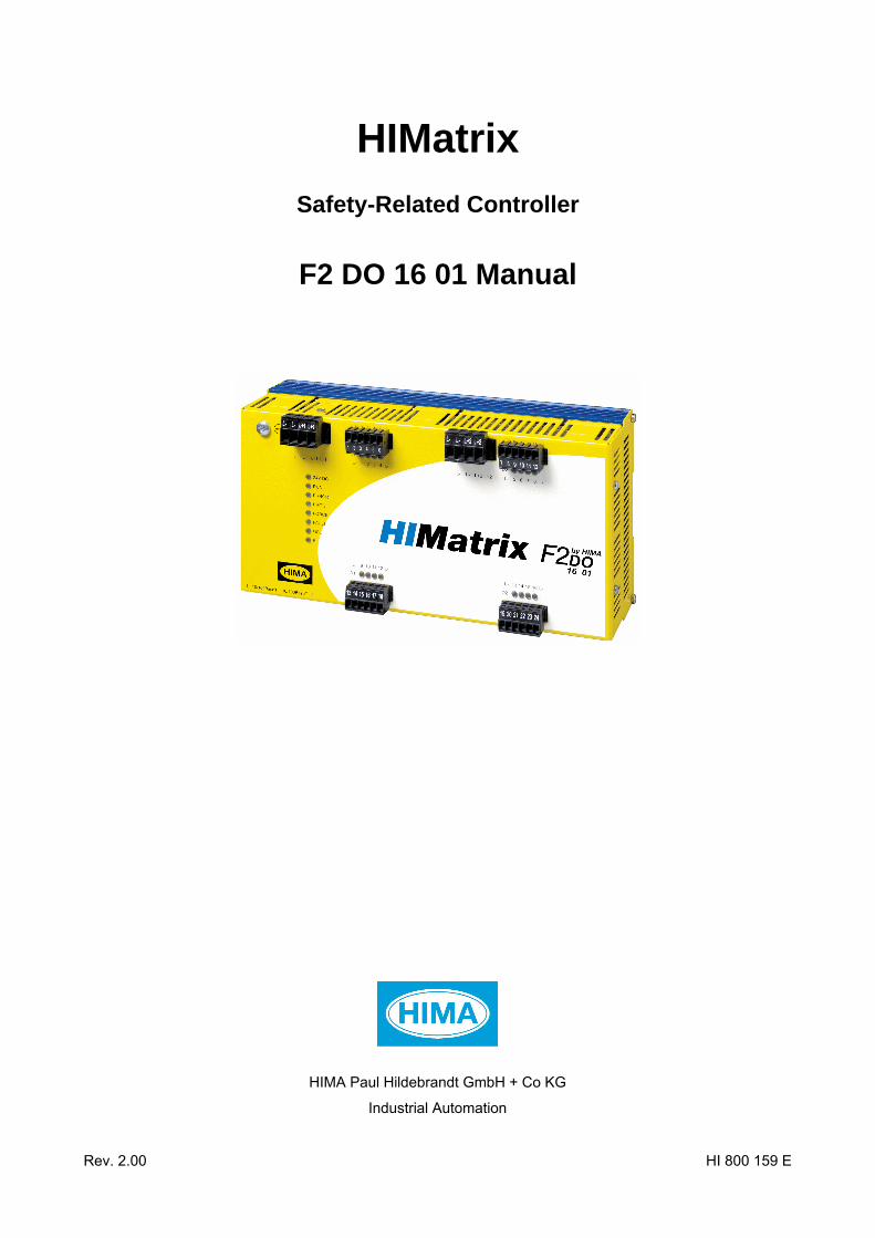
HIMatrix
Safety-Related Controller
F2 DO 16 01 Manual
HIMA Paul Hildebrandt GmbH + Co KG
Industrial Automation
Rev. 2.00 HI 800 159 E
HI 800 159 E Rev. 2.00 (1334)
All HIMA products mentioned in this manual are protected by the HIMA trade-mark. Unless noted otherwise, this also applies to other manufacturers and their respective products referred to herein.
HIMax®, HIMatrix®, SILworX®, XMR® and FlexSILon® are registered trademarks of HIMA Paul Hildebrandt GmbH + Co KG.
All of the instructions and technical specifications in this manual have been written with great care and effective quality assurance measures have been implemented to ensure their validity. For questions, please contact HIMA directly. HIMA appreciates any suggestion on which information should be included in the manual.
Equipment subject to change without notice. HIMA also reserves the right to modify the written material without prior notice.
For further information, refer to the HIMA DVD and our website at http://www.hima.de and http://www.hima.com.
© Copyright 2013, HIMA Paul Hildebrandt GmbH + Co KG
All rights reserved
Contact HIMA contact details:
HIMA Paul Hildebrandt GmbH + Co KG
P.O. Box 1261
68777 Brühl, Germany
Phone: +49 6202 709-0
Fax: +49 6202 709-107
E-mail: [email protected]
Type of change Revision index
Revisions
technical editorial
1.00 Added: Configuration with SILworX X X
1.01 Deleted: Chapter Monitoring the Temperature State integrated in the system manual
X
2.00 Revised: Chapters 3.4.1 and 3.4.2.1 Added: F2 DO 16 024, SIL 4 certified according to EN 50126, EN 50128 and EN 50129, Chapter 4.1.3
X X

F2 DO 16 01 Table of Contents
HI 800 159 E Rev. 2.00 Page 3 of 40
Table of Contents
1 Introduction 5
1.1 Structure and Use of this Manual 5
1.2 Target Audience 6
1.3 Formatting Conventions 7 1.3.1 Safety Notes 7 1.3.2 Operating Tips 8
2 Safety 9
2.1 Intended Use 9 2.1.1 Environmental Requirements 9 2.1.2 ESD Protective Measures 9
2.2 Residual Risk 10
2.3 Safety Precautions 10
2.4 Emergency Information 10
3 Product Description 11
3.1 Safety Function 11 3.1.1 Safety-Related Digital Outputs 11 3.1.1.1 Reaction in the Event of a Fault 12
3.2 Equipment, Scope of Delivery 13 3.2.1 IP Address and System ID (SRS) 13
3.3 Type Label 14
3.4 Assembly 15 3.4.1 LED Indicators 16 3.4.1.1 Operating Voltage LED 16 3.4.1.2 System LEDs 16 3.4.1.3 Communication LEDs 17 3.4.1.4 I/O LEDs 17
3.4.2 Communication 18 3.4.2.1 Connections for Ethernet Communication 18 3.4.2.2 Network Ports Used for Ethernet Communication 18
3.4.3 Reset Key 19
3.5 Product Data 20 3.5.1 Product Data F2 DO 16 014 21
3.6 Certified HIMatrix F2 DO 16 01 21
4 Start-up 22
4.1 Installation and Mounting 22 4.1.1 Connecting the Digital Outputs 22 4.1.2 Connecting the Operating Voltage 23 4.1.3 Cable plugs 23 4.1.4 Mounting the F2 DO 16 01 in Zone 2 24
4.2 Configuration 25
Table of Contents F2 DO 16 01
Page 4 of 40 HI 800 159 E Rev. 2.00
4.3 Configuration with SILworX 25 4.3.1 Parameters and Error Codes for the Output 25 4.3.2 Digital Outputs for F2 DO 16 01 25
4.3.2.1 Tab: Module 26 4.3.2.2 Tab: DO 16: Channels 27
4.4 Configuration with ELOP II Factory 27 4.4.1 Configuring the Outputs 27 4.4.2 Signals and Error Codes for the Output 27 4.4.3 Digital Outputs for F2 DO 16 01 28
5 Operation 29
5.1 Handling 29
5.2 Diagnosis 29
6 Maintenance 30
6.1 Faults 30
6.2 Maintenance Measures 30 6.2.1 Loading the Operating System 30 6.2.2 Proof Test 30
7 Decommissioning 31
8 Transport 32
9 Disposal 33
Appendix 35
Glossary 35
Index of Figures 36
Index of Tables 37
Index 38
F2 DO 16 01 1 Introduction
HI 800 159 E Rev. 2.00 Page 5 of 40
1 Introduction This manual describes the technical characteristics of the device and its use. It provides information on how to install, start up and configure the module.
1.1 Structure and Use of this Manual The content of this manual is part of the hardware description of the HIMatrix programmable electronic system.
This manual is organized in the following main chapters:
Introduction
Safety
Product Description
Start-up
Operation
Maintenance
Decommissioning
Transport
Disposal
HIMatrix remote I/Os are available for the programming tools SILworX and ELOP II Factory. Which programming tool can be used, depends on the processor operating system of the HIMatrix remote I/O, refer to the following table:
Programming tool Processor operating system
SILworX CPU OS V7 and higher
ELOP II Factory CPU OS up to V6.x
Table 1: Programming Tools for HIMatrix Remote I/Os
In the manual, the differences are specified by using:
Separated chapters,
Tables differentiating among the versions
i Projects created with ELOP II Factory cannot be edited with SILworX, and vice versa!
i Compact controllers and remote I/Os are referred to as devices.

1 Introduction F2 DO 16 01
Page 6 of 40 HI 800 159 E Rev. 2.00
Additionally, the following documents must be taken into account:
Name Content Document number
HIMatrix System Manual Compact Systems
Hardware description of the HIMatrix compact systems
HI 800 141 E
HIMatrix System Manual Modular System F60
Hardware description of the HIMatrix modular system
HI 800 191 E
HIMatrix Safety Manual Safety functions of the HIMatrix system HI 800 023 E
HIMatrix Safety Manual for Railway Applications
Safety functions of the HIMatrix system using the HIMatrix in railway applications
HI 800 437 E
SILworX Online Help Instructions on how to use SILworX -
ELOP II Factory Online Help
Instructions on how to use ELOP II Factory, Ethernet IP protocol
-
SILworX First Steps Introduction to SILworX using the HIMax system as an example
HI 801 103 E
ELOP II Factory First Steps Introduction to ELOP II Factory HI 800 006 E
Table 2: Additional Relevant Documents
The latest manuals can be downloaded from the HIMA website at www.hima.com. The revision index on the footer can be used to compare the current version of existing manuals with the Internet edition.
1.2 Target Audience This document addresses system planners, configuration engineers, programmers of automation devices and personnel authorized to implement, operate and maintain the modules and systems. Specialized knowledge of safety-related automation systems is required.
F2 DO 16 01 1 Introduction
HI 800 159 E Rev. 2.00 Page 7 of 40
1.3 Formatting Conventions To ensure improved readability and comprehensibility, the following fonts are used in this document:
Bold To highlight important parts. Names of buttons, menu functions and tabs that can be clicked and used in the programming tool.
Italics For parameters and system variables Courier Literal user inputs RUN Operating state are designated by capitals Chapter 1.2.3 Cross references are hyperlinks even though they are not particularly
marked. When the cursor hovers over a hyperlink, it changes its shape. Click the hyperlink to jump to the corresponding position.
Safety notes and operating tips are particularly marked.
1.3.1 Safety Notes The safety notes are represented as described below. These notes must absolutely be observed to reduce the risk to a minimum. The content is structured as follows:
Signal word: warning, caution, notice
Type and source of risk
Consequences arising from non-observance
Risk prevention
The signal words have the following meanings:
Warning indicates hazardous situation which, if not avoided, could result in death or serious injury.
Caution indicates hazardous situation which, if not avoided, could result in minor or modest injury.
Notice indicates a hazardous situation which, if not avoided, could result in property damage.
NOTE
Type and source of damage!
Damage prevention
SIGNAL WORD
Type and source of risk!
Consequences arising from non-observance
Risk prevention

1 Introduction F2 DO 16 01
Page 8 of 40 HI 800 159 E Rev. 2.00
1.3.2 Operating Tips Additional information is structured as presented in the following example:
i The text corresponding to the additional information is located here.
Useful tips and tricks appear as follows:
TIP The tip text is located here.

F2 DO 16 01 2 Safety
HI 800 159 E Rev. 2.00 Page 9 of 40
2 Safety All safety information, notes and instructions specified in this document must be strictly observed. The product may only be used if all guidelines and safety instructions are adhered to.
This product is operated with SELV or PELV. No imminent risk results from the product itself. The use in Ex-zone is permitted if additional measures are taken.
2.1 Intended Use HIMatrix components are designed for assembling safety-related controller systems.
When using the components in the HIMatrix system, comply with the following general requirements.
2.1.1 Environmental Requirements Requirement type Range of values 1)
Protection class Protection class III in accordance with IEC/EN 61131-2
Ambient temperature 0...+60 °C
Storage temperature -40...+85 °C
Pollution Pollution degree II in accordance with IEC/EN 61131-2
Altitude < 2000 m
Housing Standard: IP20
Supply voltage 24 VDC 1) The values specified in the technical data apply and are decisive for devices with extended
environmental requirements.
Table 3: Environmental Requirements
Exposing the HIMatrix system to environmental conditions other than those specified in this manual can cause the HIMatrix system to malfunction.
2.1.2 ESD Protective Measures Only personnel with knowledge of ESD protective measures may modify or extend the system or replace devices.
NOTE
Device damage due to electrostatic discharge! When performing the work, make sure that the workspace is free of static, and wear
an ESD wrist strap. If not used, ensure that the device is protected from electrostatic discharge, e.g., by
storing it in its packaging.
2 Safety F2 DO 16 01
Page 10 of 40 HI 800 159 E Rev. 2.00
2.2 Residual Risk No imminent risk results from a HIMatrix system itself.
Residual risk may result from:
Faults related to engineering
Faults related to the user program
Faults related to the wiring
2.3 Safety Precautions Observe all local safety requirements and use the protective equipment required on site.
2.4 Emergency Information A HIMatrix system is a part of the safety equipment of a site. If a device or a module fails, the system enters the safe state.
In case of emergency, no action that may prevent the HIMatrix systems from operating safely is permitted.
F2 DO 16 01 3 Product Description
HI 800 159 E Rev. 2.00 Page 11 of 40
3 Product Description The safety-related F2 DO 16 01 remote I/O is a compact system in a metal housing with 16 digital outputs.
The remote I/O is available in various model variants for SILworX and ELOP II Factory, see Table 4.
Remote I/Os are connected to individual HIMax or HIMatrix controllers via safeethernet. They are used to extend the I/O level, but are not able to run any user program by themselves.
The remote I/O is suitable for mounting in Ex-zone 2, see Chapter 4.1.4.
The device is TÜV-certified for safety-related applications up to SIL 3 (IEC 61508, IEC 61511 and IEC 62061), Cat. 4 and PL e (EN ISO 13849-1) and SIL 4 (EN 50126, EN 50128 and EN 50129). Further safety standards, application standards and test standards are specified in the certificates available on the HIMA website.
3.1 Safety Function The remote I/O is equipped with safety-related outputs. These outputs are safely assigned their values by the connected controller via safeethernet.
3.1.1 Safety-Related Digital Outputs The remote I/O is equipped with 16 digital outputs. The state (HIGH, LOW) of each output is signaled by an individual LED (HIGH, LOW).
Up to the maximum ambient temperature (60 °C), each of the 16 outputs can be loaded with a maximum of 2 A. For thermal reasons, HIMA does not recommend loading adjacent outputs with 2 A.
Within a temperature range of 60…70 °C, all outputs of the F2 DO 16 014 can be loaded with 0.5 A, see Table 13.
The external wire of an output is not monitored, however, a detected short-circuit is signaled.
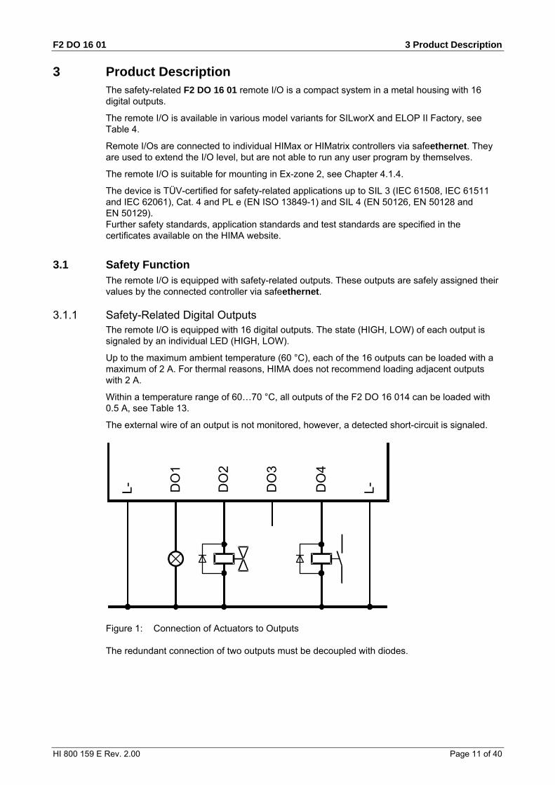
DO
1
L- DO
2
DO
3
DO
4
L-
Figure 1: Connection of Actuators to Outputs
The redundant connection of two outputs must be decoupled with diodes.
3 Product Description F2 DO 16 01
Page 12 of 40 HI 800 159 E Rev. 2.00
WARNING
For connecting a load to a 1-pole switching output, use the corresponding L- ground of the respective channel group (2-pole connection) to ensure that the internal protective circuit can function.
Inductive loads may be connected with no free-wheeling diode on the actuator. However, HIMA strongly recommends connecting a protective diode directly to the actuator.
If communication is lost, the output is set to the initial value configured. This effect must be taken into account for the behavior of the connected output.
If an overload occurs, one or all digital outputs are switched off. If the overload is removed, the outputs are switched on again automatically, see Table 12.
3.1.1.1 Reaction in the Event of a Fault If the device detects a faulty signal on a digital output, the affected module output is set to the safe (de-energized) state using the safety switches.
If a device fault occurs, all digital outputs are switched off.
In both cases, the devices activates the FAULT LED.
The error code allows the user to configure additional fault reactions in the user program.

F2 DO 16 01 3 Product Description
HI 800 159 E Rev. 2.00 Page 13 of 40
3.2 Equipment, Scope of Delivery The following table specifies the available remote I/O variants:
Designation Description
F2 DO 16 01 Remote I/O (16 digital outputs), Operating temperature: 0...+60 °C, for ELOP II Factory programming tool
F2 DO 16 014 Remote I/O (16 digital outputs), Operating temperature: -25...+70 °C (temperature class T1), Vibration and shock tested according to EN 50125-3 and EN 50155, class 1B according to IEC 61373, for ELOP II Factory programming tool
F2 DO 16 01 SILworX
Remote I/O (16 digital outputs), Operating temperature: 0...+60 °C, for SILworX programming tool
F2 DO 16 014 SILworX
Remote I/O (16 digital outputs), Operating temperature: -25...+70 °C (temperature class T1), Vibration and shock tested according to EN 50125-3 and EN 50155, class 1B according to IEC 61373, for SILworX programming tool
Table 4: Available Variants
3.2.1 IP Address and System ID (SRS) A transparent label is delivered with the device to allow one to note the IP address and the system ID (SRS for system rack slot) after a change.
IP___.___.___.___SRS____.__.__
Default value for IP address: 192.168.0.99
Default value for SRS: 60 000.200.0 (SILworX)
60 000.0.0 (ELOP II Factory)
The label must be affixed such that the ventilation slots in the housing are not obstructed.
Refer to the First Steps manual of the programming tool for more information on how to modify the IP address and the system ID.
3 Product Description F2 DO 16 01
Page 14 of 40 HI 800 159 E Rev. 2.00
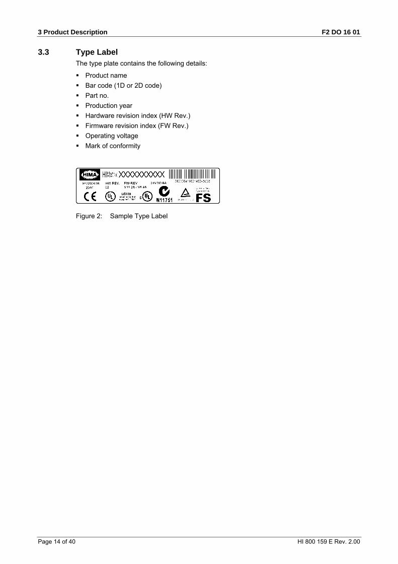
3.3 Type Label The type plate contains the following details:
Product name
Bar code (1D or 2D code)
Part no.
Production year
Hardware revision index (HW Rev.)
Firmware revision index (FW Rev.)
Operating voltage
Mark of conformity
Figure 2: Sample Type Label
F2 DO 16 01 3 Product Description
HI 800 159 E Rev. 2.00 Page 15 of 40
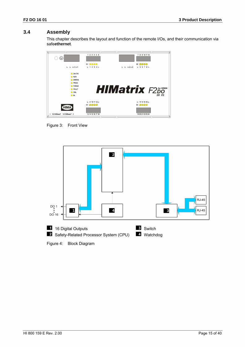
3.4 Assembly This chapter describes the layout and function of the remote I/Os, and their communication via safeethernet.
DO16 01
2
Figure 3: Front View
DO 1
DO 16 1
2
34
RJ-45
RJ-45
16 Digital Outputs
Safety-Related Processor System (CPU)
Switch
Watchdog
Figure 4: Block Diagram

3 Product Description F2 DO 16 01
Page 16 of 40 HI 800 159 E Rev. 2.00
3.4.1 LED Indicators The light-emitting diodes (LEDs) indicate the operating state of the remote I/O. The LEDs are classified as follows:
Operating voltage LED
System LEDs
Communication LEDs
I/O LEDs
3.4.1.1 Operating Voltage LED LED Color Status Description
On 24 VDC operating voltage present 24 VDC Green Off No operating voltage
Table 5: Operating Voltage LED
3.4.1.2 System LEDs While the system is being booted, all LEDs are lit simultaneously.
LED Color Status Description
On Device in RUN, normal operation
Blinking Device in STOP A new operating system is being loaded.
RUN Green
Off The device is not in the RUN state.
On The device is in the ERROR STOP state. Internal fault detected by self-tests, e.g., hardware faults or cycle time overrun. The processor system can only be restarted with a command from the PADT (reboot).
Blinking If ERROR blinks and all others LEDs are lit simultaneously, the boot loader has detected an operating system fault in the flash memory and waits for a new operating system to be loaded.
ERROR Red
Off No faults detected.
On A new configuration is being loaded into the device.
Blinking The device switches from INIT to STOP A new operating system is being loaded into the flash ROM.
PROG Yellow
Off No configuration or operating system is being loaded.
FORCE Yellow Off The FORCE LED of a remote I/O is not functioning. The FORCE LED of the associated controller serves to signal the forcing of a remote I/O.
On The loaded configuration is not valid. The new operating system is corrupted (after OS download).
Blinking Fault while loading a new operating system One or multiple I/O faults occurred.
FAULT Yellow
Off None of the described faults occurred.
Blinking Operating system emergency loader active. OSL Yellow Off Operating system emergency loader inactive.
Blinking OS and OSL binary defective or hardware fault, INIT_FAIL. BL Yellow Off None of the described faults occurred.
Table 6: System LEDs
F2 DO 16 01 3 Product Description
HI 800 159 E Rev. 2.00 Page 17 of 40
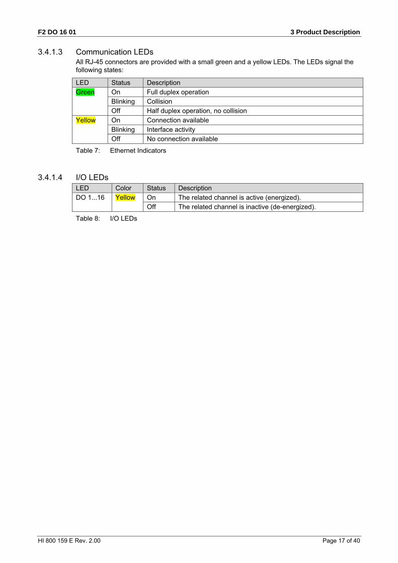
3.4.1.3 Communication LEDs All RJ-45 connectors are provided with a small green and a yellow LEDs. The LEDs signal the following states:
LED Status Description
On Full duplex operation
Blinking Collision
Green
Off Half duplex operation, no collision
On Connection available
Blinking Interface activity
Yellow
Off No connection available
Table 7: Ethernet Indicators
3.4.1.4 I/O LEDs LED Color Status Description
On The related channel is active (energized). DO 1...16 Yellow Off The related channel is inactive (de-energized).
Table 8: I/O LEDs

3 Product Description F2 DO 16 01
Page 18 of 40 HI 800 159 E Rev. 2.00
3.4.2 Communication The remote I/O communicates with the associated controller via safeethernet.
3.4.2.1 Connections for Ethernet Communication Property Description
Ports 2 x RJ-45
Transfer standard 10BASE-T/100BASE-Tx, half and full duplex
Auto negotiation Yes
Auto crossover Yes
IP address Freely configurable1)
Subnet mask Freely configurable1)
Supported protocols Safety-related: safeethernet Standard protocols: Programming and debugging tool
(PADT), SNTP 1) The general rules for assigning IP address and subnet masks must be adhered to.
Table 9: Ethernet Interfaces Properties
The two RJ-45 connectors with integrated LEDs are located on the bottom left-hand side of the housing. For more information on the communication LEDs, refer to Chapter 3.4.1.3.
The connection parameters are read based on the MAC address (media access control address) defined during manufacturing.
The MAC address for the remote I/O is specified on a label located above the two RJ-45 connectors (1 and 2).
Figure 5: Sample MAC Address Label
The remote I/O is equipped with an integrated switch for Ethernet communication. For further information on the integrated switch and safeethernet, refer to Chapter Communication of the system manual for compact systems (HI 800 141 E).
3.4.2.2 Network Ports Used for Ethernet Communication UDP ports Use
8000 Programming and operation with the programming tools
8001 Configuration of the remote I/O using the PES (ELOP II Factory)
8004 Configuration of the remote I/O using the PES (SILworX)
6010 safeethernet
123 SNTP (time synchronization between PES and remote I/O, PES and external devices)
Table 10: Network Ports in Use

F2 DO 16 01 3 Product Description
HI 800 159 E Rev. 2.00 Page 19 of 40
3.4.3 Reset Key The remote I/O is equipped with a reset key. The key is only required if the user name or password for administrator access is not known. If only the IP address set for the remote I/O does not match the PADT (PC), the connection can be established with a Route add entry on the PC.
i Only the model variants without protective lacquer are equipped with a reset key.
The key can be accessed through a small round hole located approximately 5 cm from the upper left-hand side of the housing. The key is engaged using a suitable pin made of insulating material to avoid short-circuits within the remote I/O.
The reset is only effective if the remote I/O is rebooted (switched off and on) while the key is simultaneously engaged for at least 20 s. Engaging the key during operation has no effect.
Properties and behavior of the remote I/IO after a reboot with engaged reset key:
Connection parameters (IP address and system ID) are set to the default values.
All accounts are deactivated except for the administrator default account with empty password.
After a new reboot without the reset key engaged, the connection parameters (IP address and system ID) and accounts become effective.
Those configured by the user.
Those valid prior to rebooting with the reset key engaged, if no changes were performed.

3 Product Description F2 DO 16 01
Page 20 of 40 HI 800 159 E Rev. 2.00
3.5 Product Data
General
Response time ≥ 20 ms
Ethernet interfaces 2 x RJ-45, 10BASE-T/100BASE-Tx with integrated switch
Operating voltage 24 VDC, -15...+20 %, rPP ≤ 15 %, from a power supply unit with safe insulation in accordance with IEC 61131-2
Current input max. 9 A per group Idle: approx. 0.2 A per group at 24 V
Fuse (external) 10 A time-lag (T)
Back-up battery None
Operating temperature 0...+60 °C
Storage temperature -40...+85 °C
Type of protection IP20
Max. dimensions (without plug)
Width: 207 mm (with housing screws) Height: 114 mm (with fixing bolt) Depth: 66 mm (with earthing screw)
Weight approx. 0.9 kg
Table 11: Product Data
Digital outputs
Number of outputs 16 (non-galvanically separated)
Output voltage L+ minus 2 V
Output current max. 2 A at < 40 °C max. 1 A at 40…60 °C
Current per group Total permissible current
max. 8 A max. 16 A
Minimum load 2 mA for each channel
Lamp load max. 10 W (with output 1 A) max. 25 W (with output 2 A)
Inductive load max. 500 mH
Internal voltage drop max. 2 V at 2 A
Leakage current (with low level)
max. 1 mA at 2 V
Behavior upon overload The affected output is switched off and cyclically switched on again
Table 12: Specifications for the Digital Outputs
F2 DO 16 01 3 Product Description
HI 800 159 E Rev. 2.00 Page 21 of 40
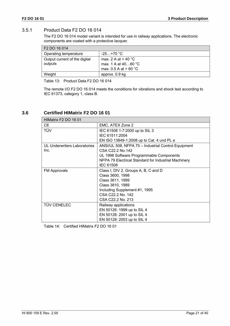
3.5.1 Product Data F2 DO 16 014 The F2 DO 16 014 model variant is intended for use in railway applications. The electronic components are coated with a protective lacquer.
F2 DO 16 014
Operating temperature -25…+70 °C
Output current of the digital outputs
max. 2 A at < 40 °C max. 1 A at 40…60 °C max. 0.5 A at > 60 °C
Weight approx. 0.9 kg
Table 13: Product Data F2 DO 16 014
The remote I/O F2 DO 16 014 meets the conditions for vibrations and shock test according to IEC 61373, category 1, class B.
3.6 Certified HIMatrix F2 DO 16 01
HIMatrix F2 DO 16 01
CE EMC, ATEX Zone 2
TÜV IEC 61508 1-7:2000 up to SIL 3 IEC 61511:2004 EN ISO 13849-1:2008 up to Cat. 4 und PL e
UL Underwriters Laboratories Inc.
ANSI/UL 508, NFPA 70 – Industrial Control Equipment CSA C22.2 No.142 UL 1998 Software Programmable Components NFPA 79 Electrical Standard for Industrial Machinery IEC 61508
FM Approvals Class I, DIV 2, Groups A, B, C and D Class 3600, 1998 Class 3611, 1999 Class 3810, 1989 Including Supplement #1, 1995 CSA C22.2 No. 142 CSA C22.2 No. 213
TÜV CENELEC Railway applications EN 50126: 1999 up to SIL 4 EN 50128: 2001 up to SIL 4 EN 50129: 2003 up to SIL 4
Table 14: Certified HIMatrix F2 DO 16 01
4 Start-up F2 DO 16 01
Page 22 of 40 HI 800 159 E Rev. 2.00
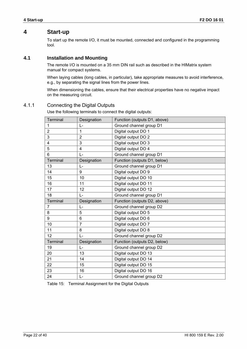
4 Start-up To start up the remote I/O, it must be mounted, connected and configured in the programming tool.
4.1 Installation and Mounting The remote I/O is mounted on a 35 mm DIN rail such as described in the HIMatrix system manual for compact systems.
When laying cables (long cables, in particular), take appropriate measures to avoid interference, e.g., by separating the signal lines from the power lines.
When dimensioning the cables, ensure that their electrical properties have no negative impact on the measuring circuit.
4.1.1 Connecting the Digital Outputs Use the following terminals to connect the digital outputs:
Terminal Designation Function (outputs D1, above)
1 L- Ground channel group D1
2 1 Digital output DO 1
3 2 Digital output DO 2
4 3 Digital output DO 3
5 4 Digital output DO 4
6 L- Ground channel group D1
Terminal Designation Function (outputs D1, below)
13 L- Ground channel group D1
14 9 Digital output DO 9
15 10 Digital output DO 10
16 11 Digital output DO 11
17 12 Digital output DO 12
18 L- Ground channel group D1
Terminal Designation Function (outputs D2, above)
7 L- Ground channel group D2
8 5 Digital output DO 5
9 6 Digital output DO 6
10 7 Digital output DO 7
11 8 Digital output DO 8
12 L- Ground channel group D2
Terminal Designation Function (outputs D2, below)
19 L- Ground channel group D2
20 13 Digital output DO 13
21 14 Digital output DO 14
22 15 Digital output DO 15
23 16 Digital output DO 16
24 L- Ground channel group D2
Table 15: Terminal Assignment for the Digital Outputs

F2 DO 16 01 4 Start-up
HI 800 159 E Rev. 2.00 Page 23 of 40
4.1.2 Connecting the Operating Voltage Each group includes 8 channels. The two groups are supplied individually with separate operating voltages, however, both clamp terminal blocks must be connected.
A group's total current input must not exceed 9 A. If a group exceeds the total current input, it is switched off and then switched on again cyclically.
Group Clamp terminal block Output channels
D1 (left) L-, L-, L+1, L+1 1...4 and 9...12
D2 (right) L-, L-, L+2, L+2 5...8 and 13...16
Table 16: Connecting the Operating Voltage
4.1.3 Cable plugs Cable plugs attached to the pin headers of the devices are used to connect to the power supply and to the field zone. The cable plugs are included within the scope of delivery of the HIMatrix devices and modules.
The devices power supply connections feature the following properties:
Connection to the power supply
Cable plugs 2 pieces, four poles, screw terminals
Wire cross-section 0.2…2.5 mm2 (single-wire) 0.2…2.5 mm2 (finely stranded) 0.2…2.5 mm2 (with wire end ferrule)
Stripping length 10 mm
Screwdriver Slotted 0.6 x 3.5 mm
Tightening torque 0.4…0.5 Nm
Table 17: Power Supply Cable Plug Properties
Connection to the field zone
Number of cable plugs 4 pieces, six poles, screw terminals
Wire cross-section 0.2…1.5 mm2 (single-wire) 0.2…1.5 mm2 (finely stranded) 0.2…1.5 mm2 (with wire end ferrule)
Stripping length 6 mm
Screwdriver Slotted 0.4 x 2.5 mm
Tightening torque 0.2…0.25 Nm
Table 18: Input and Output Cable Plug Properties

4 Start-up F2 DO 16 01
Page 24 of 40 HI 800 159 E Rev. 2.00
4.1.4 Mounting the F2 DO 16 01 in Zone 2 (EC Directive 94/9/EC, ATEX)
The remote I/O is suitable for mounting in zone 2. Refer to the corresponding declaration of conformity available on the HIMA website.
When mounting the device, observe the special conditions specified in the following section.
Specific Conditions X 1. Mount the remote I/O in an enclosure that meets the EN 60079-15 requirements and
achieves a type of protection of at least IP54, in accordance with EN 60529. Provide the device with the following label:
Work is only permitted in the de-energized state Exception: If a potentially explosive atmosphere has been precluded, work can be also performed when the device is under voltage.
2. The enclosure in use must be able to safely dissipate the generated heat. Depending on the output load and supply voltage, the HIMatrix F2 DO 16 01 module has a power dissipation ranging between 9 W and 32 W.
3. Protect the HIMatrix F2 DO 16 01 with a 10 A time-lag fuse. The 24 VDC power must come from a power supply unit with safe isolation. Use power supply units of type PELV or SELV only.
4. Applicable standards: VDE 0170/0171 Part 16, DIN EN 60079-15: 2004-5 VDE 0165 Part 1, DIN EN 60079-14: 1998-08
Pay particular attention to the following sections
DIN EN 60079-15: Chapter 5 Design Chapter 6 Terminals and cabling Chapter 7 Air and creeping distances Chapter 14 Connectors DIN EN 60079-14: Chapter 5.2.3 Equipment for use in zone 2 Chapter 9.3 Cabling for zones 1 and 2 Chapter 12.2 Equipment for zones 1 and 2
The remote I/O is additionally equipped with the label represented below:
Figure 6: Label for Ex Conditions
F2 DO 16 01 4 Start-up
HI 800 159 E Rev. 2.00 Page 25 of 40
4.2 Configuration The remote I/O can be configured using a programming tool, SILworX or ELOP II Factory. Which programming tool should be used, depends on the revision status of the operating system (firmware):
SILworX is required for CPU OS V7 and higher.
ELOP II Factory is required for CPU OS up to V6.x.
i How to switch between operating systems is described in Chapter Loading Operating Systems of the system manual for compact systems (HI 800 141 E).
4.3 Configuration with SILworX In the Hardware Editor, the remote I/Os are represented like a base plate equipped with the following modules:
Processor module (CPU)
Output module (DO 16)
Double-click the module to open the Detail View with the corresponding tabs. The tabs are used to assign the global variables configured in the user program to the system variables of the corresponding module.
4.3.1 Parameters and Error Codes for the Output The following tables specify the system parameters that can be read and set for the outputs, including the corresponding error codes.
In the user program, the error codes can be read using the variables assigned within the logic.
The error codes can also be displayed in SILworX.
4.3.2 Digital Outputs for F2 DO 16 01 The following tables present the statuses and parameters for the output module (DO 16) in the same order as given in the Hardware Editor.
4 Start-up F2 DO 16 01
Page 26 of 40 HI 800 159 E Rev. 2.00
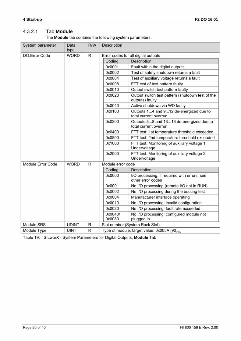
4.3.2.1 Tab Module The Module tab contains the following system parameters:
System parameter Data type
R/W Description
DO.Error Code WORD R Error codes for all digital outputs
Coding Description
0x0001 Fault within the digital outputs
0x0002 Test of safety shutdown returns a fault
0x0004 Test of auxiliary voltage returns a fault
0x0008 FTT test of test pattern faulty
0x0010 Output switch test pattern faulty
0x0020 Output switch test pattern (shutdown test of the outputs) faulty
0x0040 Active shutdown via WD faulty
0x0100 Outputs 1...4 and 9...12 de-energized due to total current overrun
0x0200 Outputs 5...8 and 13...16 de-energized due to total current overrun
0x0400 FTT test: 1st temperature threshold exceeded
0x0800 FTT test: 2nd temperature threshold exceeded
0x1000 FTT test: Monitoring of auxiliary voltage 1: Undervoltage
0x2000 FTT test: Monitoring of auxiliary voltage 2: Undervoltage
Module Error Code WORD R Module error code
Coding Description
0x0000 I/O processing, if required with errors, see other error codes
0x0001 No I/O processing (remote I/O not in RUN)
0x0002 No I/O processing during the booting test
0x0004 Manufacturer interface operating
0x0010 No I/O processing: invalid configuration
0x0020 No I/O processing: fault rate exceeded
0x0040/ 0x0080
No I/O processing: configured module not plugged in
Module SRS UDINT R Slot number (System Rack Slot)
Module Type UINT R Type of module, target value: 0x005A [90dec]
Table 19: SILworX - System Parameters for Digital Outputs, Module Tab

F2 DO 16 01 4 Start-up
HI 800 159 E Rev. 2.00 Page 27 of 40
4.3.2.2 Tab DO 16: Channels The DO 16: Channels tab contains the following system parameters.
System parameter
Data type
R/W Description
Channel no. --- R Channel number, defined by default
-> Error Code [BYTE]
BYTE R Error codes for the digital output channels
Coding Description
0x01 Fault in the digital output module
0x02 Channel shutdown due to overload
0x04 Error while reading back the control signal
0x08 Error while reading back the status of the digital outputs
Value [BOOL] ->
BOOL W Output value for DO channels: 1 = output energized 0 = output de-energized
Table 20: SILworX - System Parameters for Digital Outputs, DO 16: Channels Tab
4.4 Configuration with ELOP II Factory
4.4.1 Configuring the Outputs The signals previously defined in the Signal Editor (Hardware Management) are assigned to the individual channels (outputs) using ELOP II Factory. Refer to the system manual for compact systems or the online help for more details.
The following chapter describes the system signals used for assigning signals in the remote I/O.
4.4.2 Signals and Error Codes for the Output The following tables specify the system signals that can be read and set for the outputs, including the corresponding error codes.
In the user program, the error codes can be read using the signals assigned within the logic.
The error codes can also be displayed in ELOP II Factory.
4 Start-up F2 DO 16 01
Page 28 of 40 HI 800 159 E Rev. 2.00
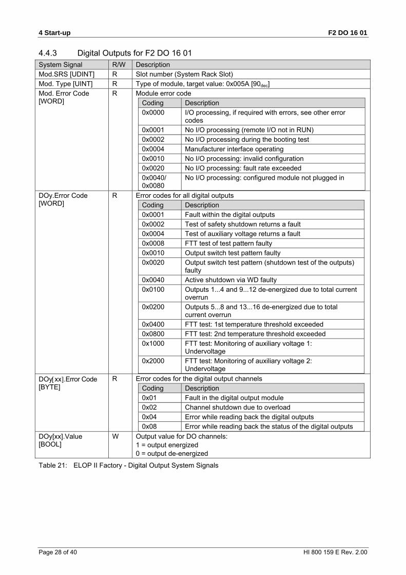
4.4.3 Digital Outputs for F2 DO 16 01 System Signal R/W Description
Mod.SRS [UDINT] R Slot number (System Rack Slot)
Mod. Type [UINT] R Type of module, target value: 0x005A [90dec]
Mod. Error Code [WORD]
R Module error code
Coding Description
0x0000 I/O processing, if required with errors, see other error codes
0x0001 No I/O processing (remote I/O not in RUN)
0x0002 No I/O processing during the booting test
0x0004 Manufacturer interface operating
0x0010 No I/O processing: invalid configuration
0x0020 No I/O processing: fault rate exceeded
0x0040/ 0x0080
No I/O processing: configured module not plugged in
DOy.Error Code [WORD]
R Error codes for all digital outputs
Coding Description
0x0001 Fault within the digital outputs
0x0002 Test of safety shutdown returns a fault
0x0004 Test of auxiliary voltage returns a fault
0x0008 FTT test of test pattern faulty
0x0010 Output switch test pattern faulty
0x0020 Output switch test pattern (shutdown test of the outputs) faulty
0x0040 Active shutdown via WD faulty
0x0100 Outputs 1...4 and 9...12 de-energized due to total current overrun
0x0200 Outputs 5...8 and 13...16 de-energized due to total current overrun
0x0400 FTT test: 1st temperature threshold exceeded
0x0800 FTT test: 2nd temperature threshold exceeded
0x1000 FTT test: Monitoring of auxiliary voltage 1: Undervoltage
0x2000 FTT test: Monitoring of auxiliary voltage 2: Undervoltage
DOyxx.Error Code [BYTE]
R Error codes for the digital output channels Coding Description
0x01 Fault in the digital output module
0x02 Channel shutdown due to overload
0x04 Error while reading back the digital outputs
0x08 Error while reading back the status of the digital outputs DOy[xx].Value [BOOL]
W Output value for DO channels: 1 = output energized 0 = output de-energized
Table 21: ELOP II Factory - Digital Output System Signals
F2 DO 16 01 5 Operation
HI 800 159 E Rev. 2.00 Page 29 of 40
5 Operation The remote I/O can only operated together with a controller. No specific monitoring is required for remote I/Os.
5.1 Handling Handling of the remote I/O during operation is not required.
5.2 Diagnosis A first diagnosis results from evaluating the LEDs, see Chapter 3.4.1.
The device diagnostic history can also be read using the programming tool.
6 Maintenance F2 DO 16 01
Page 30 of 40 HI 800 159 E Rev. 2.00
6 Maintenance No maintenance measures are required during normal operation.
If a failure occurs, the defective module or device must be replaced with a module or device of the same type or with a replacement model approved by HIMA.
Only the manufacturer is authorized to repair the device/module.
6.1 Faults Refer to Chapter 3.1.1.1, for more information on the fault reaction of digital outputs.
If the test harnesses detect safety-critical faults, the module enters the STOP_INVALID state and will remain in this state. This means that the input signals are no longer processed by the device and the outputs switch to the de-energized, safe state. The evaluation of diagnostics provides information on the fault cause.
6.2 Maintenance Measures The following measures are required for the device:
Loading the operating system, if a new version is required
Executing the proof test
6.2.1 Loading the Operating System HIMA is continuously improving the operating system of the devices. HIMA recommends to use system downtimes to load a current version of the operating system into the devices.
Refer to the release list to check the consequences of the new operation system version on the system!
The operating system is loaded using the programming tool.
Prior to loading the operating system, the device must be in STOP (displayed in the programming tool). Otherwise, stop the device.
For more information, refer to the programming tool documentation.
6.2.2 Proof Test HIMatrix devices and modules must be subjected to a proof test in intervals of 10 years. For more information, refer to the safety manual (HI 800 023 E).
F2 DO 16 01 7 Decommissioning
HI 800 159 E Rev. 2.00 Page 31 of 40
7 Decommissioning Remove the supply voltage to decommission the device. Afterwards pull out the pluggable screw terminal connector blocks for inputs and outputs and the Ethernet cables.
8 Transport F2 DO 16 01
Page 32 of 40 HI 800 159 E Rev. 2.00
8 Transport To avoid mechanical damage, HIMatrix components must be transported in packaging.
Always store HIMatrix components in their original product packaging. This packaging also provides protection against electrostatic discharge. Note that the product packaging alone is not suitable for transport.

F2 DO 16 01 9 Disposal
HI 800 159 E Rev. 2.00 Page 33 of 40
9 Disposal Industrial customers are responsible for correctly disposing of decommissioned HIMatrix hardware. Upon request, a disposal agreement can be arranged with HIMA.
All materials must be disposed of in an ecologically sound manner.

9 Disposal F2 DO 16 01
Page 34 of 40 HI 800 159 E Rev. 2.00

F2 DO 16 01 Appendix
HI 800 159 E Rev. 2.00 Page 35 of 40
Appendix
Glossary
Term Description
ARP Address resolution protocol: Network protocol for assigning the network addresses to hardware addresses
AI Analog input
AO Analog output
COM Communication module
CRC Cyclic redundancy check
DI Digital input
DO Digital output
ELOP II Factory Programming tool for HIMatrix systems
EMC Electromagnetic compatibility
EN European norm
ESD Electrostatic discharge
FB Fieldbus
FBD Function block diagrams
FTT Fault tolerance time
ICMP Internet control message protocol: Network protocol for status or error messages
IEC International electrotechnical commission
MAC address Media access control address: Hardware address of one network connection
PADT Programming and debugging tool (in accordance with IEC 61131-3), PC with SILworX or ELOP II Factory
PE Protective earth
PELV Protective extra low voltage
PES Programmable electronic system
R Read: The system variable or signal provides value, e.g., to the user program
Rack ID Base plate identification (number)
Interference-free Supposing that two input circuits are connected to the same source (e.g., a transmitter). An input circuit is termed interference-free if it does not distort the signals of the other input circuit.
R/W Read/Write (column title for system variable/signal type)
SELV Safety extra low voltage
SFF Safe failure fraction, portion of faults that can be safely controlled
SIL Safety integrity level (in accordance with IEC 61508)
SILworX Programming tool for HIMatrix systems
SNTP Simple network time protocol (RFC 1769)
SRS System.rack.slot addressing of a module
SW Software
TMO Timeout
W Write: System variable/signal is provided with value, e.g., from the user program
rPP Peak-to-peak value of a total AC component
Watchdog (WD) Time monitoring for modules or programs. If the watchdog time is exceeded, the module or program enters the ERROR STOP state.
WDT Watchdog time
Appendix F2 DO 16 01
Page 36 of 40 HI 800 159 E Rev. 2.00
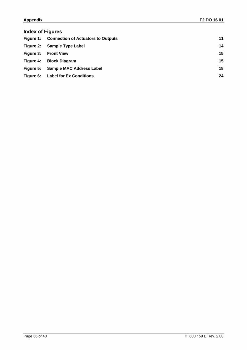
Index of Figures Figure 1: Connection of Actuators to Outputs 11
Figure 2: Sample Type Label 14
Figure 3: Front View 15
Figure 4: Block Diagram 15
Figure 5: Sample MAC Address Label 18
Figure 6: Label for Ex Conditions 24
F2 DO 16 01 Appendix
HI 800 159 E Rev. 2.00 Page 37 of 40
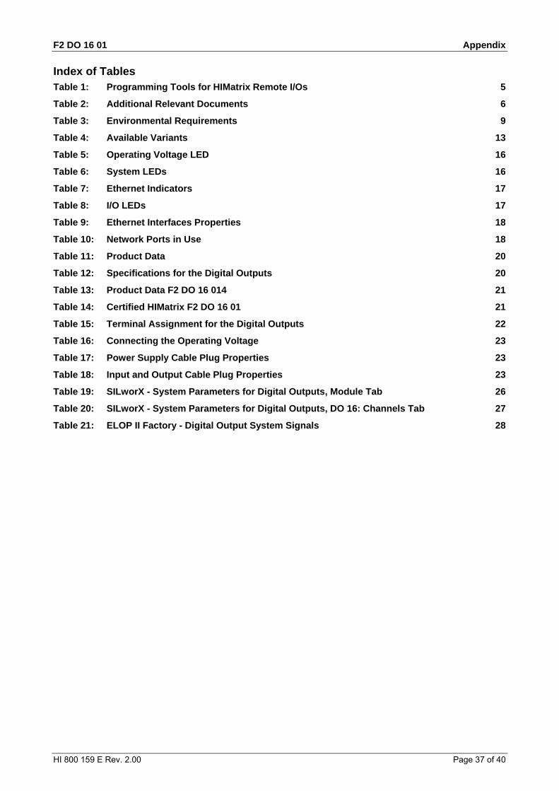
Index of Tables Table 1: Programming Tools for HIMatrix Remote I/Os 5
Table 2: Additional Relevant Documents 6
Table 3: Environmental Requirements 9
Table 4: Available Variants 13
Table 5: Operating Voltage LED 16
Table 6: System LEDs 16
Table 7: Ethernet Indicators 17
Table 8: I/O LEDs 17
Table 9: Ethernet Interfaces Properties 18
Table 10: Network Ports in Use 18
Table 11: Product Data 20
Table 12: Specifications for the Digital Outputs 20
Table 13: Product Data F2 DO 16 014 21
Table 14: Certified HIMatrix F2 DO 16 01 21
Table 15: Terminal Assignment for the Digital Outputs 22
Table 16: Connecting the Operating Voltage 23
Table 17: Power Supply Cable Plug Properties 23
Table 18: Input and Output Cable Plug Properties 23
Table 19: SILworX - System Parameters for Digital Outputs, Module Tab 26
Table 20: SILworX - System Parameters for Digital Outputs, DO 16: Channels Tab 27
Table 21: ELOP II Factory - Digital Output System Signals 28
Appendix F2 DO 16 01
Page 38 of 40 HI 800 159 E Rev. 2.00
Index block diagram..............................................15 diagnosis.....................................................29 fault reaction
digital outputs ..........................................12 front view.....................................................15
safeethernet .............................................. 18 safety function ............................................ 11 specifications.............................................. 20 SRS............................................................ 13


(1334)
HIMA Paul Hildebrandt GmbH + Co KG
P.O. Box 1261
68777 Brühl, Germany
Phone: +49 6202 709-0
Fax: +49 6202 709-107
E-mail: [email protected] Internet: www.hima.com
HI 8
00 1
59 E
©
by
HIM
A P
aul H
ildeb
rand
t G
mbH
+ C
o K
G