Embed Size (px)
Citation preview

Himalayan Ground Conditions challenge innovation for successful TBM Tunnelling
T.G. Carter Golder Associates, Toronto, Canada
ABSTRACT: From the tunnelling perspective, the Himalayas arguably pose the most challenging ground conditions almost anywhere in the world. One of the prime reasons for this is that they are the youngest of the mountain chains. They are demonstrably rising faster than anywhere else. Their composition is also younger generally, and in consequence less well consolidated than all of the other older fold belts. This is consistent with the fact that they constitute one of the most active of the plate margin zones, rising at a rate that is almost double that of the Andes, which, in turn is almost three times that of the Alps. Almost nowhere else, on a world scale, except around the Pacific Ring of Fire, is even on the same active “stress” scale. As insitu stress levels are to a large extent geologic age dependent the younger the mountain belts the more imbalanced is the stress state. Even though impressively rugged, the Canadian Rockies and West Coast Ranges of North America, the Urals of Central Russia, or the coastal ranges of Norway are largely benign from a stress imbalance perspective. As a result, stress conditions (magnitude and variation) can potentially be more extreme and adverse on a Himalayan tunnelling project than even has been encountered in some of the worst sub-mountain tunnel drives (including the Olmos and Yacambu Tunnels of Peru and Colombia respectively, which are landmark projects from the bursting and squeezing perspective). On a ranking scale, these Andean tunnels traversed much worse ground conditions and arguably met greater geotechnical challenges than were encountered anywhere along the 50+ km length of the Lötchberg and Alp Base deep tunnel drives, echoing the fact that the level of active out-of-balance deviatoric stress state experienced by these tunnels is likely mountain range dependent. One can thus postulate a tunnelling difficulty ranking scale for the mountain chains of the world, viz., – #1 the Himalayas, arguably the most difficult and challenging, through #2 the Andes and #3 the Alps, through to #4 the least difficult of the main chains, the Rockies and the Western Cordillera, with #5, 6, 7 corresponding to older and older mountain cores – with the Archean Canadian and Scandinavian, Algonquin and Adinondak age mountain belts being almost totally benign stress-wise. This is not to say that there aren’t adverse faults and challenging zones of poor ground in even these old mountain range areas. The dominant difference relates to stress state.
Based on “active” stress state alone, therefore, similar length deep tunnel excavations under the Himalayas likely will pose significantly more challenges than an equal length, equal cover drive almost anywhere else in the world. These difficulties of tunnelling at depth through high mountainous terrain pose major challenges not just for tunnel boring machine (TBM) drivages but also for application of traditional drill and blast (D&B) and NATM methods. Dealing with adverse geology at any depth can be problematic and can lead to significant tunnelling delays if not adequately foreseen; but geological problem conditions, which might be tractable at shallow depth, with either TBM’s or D&B approaches, when encountered at significant depth (>1000m) can prove disastrous depending on stress state, rock competence and prevailing groundwater inflows. Mitigating delay problems associated with exceptionally bad ground at depth requires considerable foresight and advanced planning. The more challenging the ground, the greater the pre-planning that is required prior to tunnelling. This challenge is not just one of tackling the adverse ground condition, by modifying the excavation and support processes in order to deal with the specific problem zone, stress state and groundwater conditions, it is also often about logistics, as all too often for deep tunnels in mountainous regions the problem geologic zones are at significant distance from the nearest portal, and at such significant depth that surface pre-treatment is generally impractical.
Traversing faulted and disturbed ground at significant depth requires that tunnelling procedures be able to cope with a huge range of difficult geological conditions. Investigating, evaluating and assessing anticipated geology ahead of tunnelling, and dealing with encountered difficult ground conditions requires that better understanding be gained of the interaction between complex geology and stress conditions when excavating at significant depths. Extremes of ground conditions present major contrasts to tunnelling, so much so that they often demand use of flexible rock engineering solutions in order for the tunnel to progress. The fact that within the Himalayas, conditions can be expected to be as bad as has ever been encountered elsewhere means that there has to be the ability while tunnelling to allow changes to be made of driving method and support approaches. This need to adopt flexible solutions is often seen as being at variance with the constraints imposed by the rigidity of design elements incorporated into the fabrication of a typical TBM. As a result, traditionally there has been a reluctance to use machines in these conditions, mainly due to the perceived extremely adverse consequences of entrapping or damaging the TBM. In some part this is due to the perception that there is more difficulty dealing with adverse ground conditions in the confined working area of a TBM, in comparison to dealing with the same problem in the larger working space of a D&B/NATM heading. Hard rock machine designs are however moving forward to encompass full umbrella forepoling and soft rock machine pre-grouting and ground treatment philosophies in an attempt to combat some of these problems by making the machines sufficiently robust and at the same time flexible enough to be capable of safely and successfully excavating through extremely bad ground.
Presented at: Hydrovision India 2011, SESSION 5c: (Risk Management in Tunnelling) KEYWORDS: (tunnelling, TBM, D&B, NATM, risks, hazards, squeezing, spalling, bursts, rockmass characterization)

2
1 INTRODUCTION
Two issues essentially control our ability to succesfully improve tunnelling effectiveness for traversing through the characteristically complicated ground conditions found beneath the mountainous regions of the world – (i) influence of adverse geotechnics, (Figure 1) ie., dealing with difficult ground conditions created by stress state, groundwater conditions and/or prevailing rock quality and (ii) limitations of current tunnelling technology (ranging from drill and blast (D&B) and NATM methods through various Tunnel Boring Machine (TBM) types). Tunnelling in adverse ground is significantly less forgiving of limitations of tunnelling approach than tunnelling in good ground. Generally the more difficult the ground the more flexibility is also needed. Tunnelling in the Himalayas, the Andes and until recently the Alps, has shied away from TBM use due to perceived inflexibility, and the high likelihood of them getting trapped by adverse ground conditions – either as a result of squeezing or spalling/bursting conditions or because of ground collapses associated with rockfalls or with running or flowing ground within faults, always in
these cases complicated by heavy water inflows. As illustrated in Figure 1, any of these situations can lead to problematic tunnelling at best, and at worst collapses and abandonment. Dealing with such problems is always challenging, but is ten times worse when the tunnel heading is 10km from the nearest portal, as is the case in many TBM drives. The fact that such conditions pose almost as many challenges for conventional D&B/NATM methods as for a
modern machine drive often gets ignored. When similar conditions are met and encountered in D&B headings sometimes it can take as long or longer to negotiate the problem zone than it might have taken with a properly configured well operated machine.
The perception issue that there is a significant difference between D&B/NATM and TBM’s in their ability to cope with adverse conditions is addressed by Verman et al, 2011, largely from the viewpoint of comparative pre-established geotechnical risk. Here, differences in tunnelling approach and methodology are explored from the viewpoint of their ability to cope with difficult ground conditions; and, based on review of case records some advantages and limitations of currently available methods are highlighted and suggestions for path forward development suggested.
2 GEOTECHNICAL CHARACTERIZATION
Three main geotechnical elements control our ability to execute trouble free tunnels at significant depth – stress state, groundwater conditions and the rock itself, Figure 2. Adverse characteristics of any one of these three elements can, on its own, compromise D&B or TBM tunnelling but it usually takes a combination of all three being adverse to trap a machine or halt a drill and blast drive, to the extent that a by-pass becomes necessary.
We have methods to characterize each, at least at an overview level of assessment – (i) stress, in terms of the ratio of rock strength to major principal stress, and thence simple definition through use of the SRF parameter of the Q-system (Barton, et al. 1974, 1976), – (ii) water, through the groundwater characterization descriptions in either the
Figure 2 – Primary Risk Elements and Geotechnical Definition Measures
Figure 1 Range of Adverse Conditions often encounterd in deep tunnels in mountain areas

3
Q and/or RMR classifications (Bieniawski, 1973, 1976), and – (iii) rock mass quality by means of Q′, RMR′76, GSI (Marinos and Hoek, 2000) and/or RMi (Palmström, 2000), where the prime on the Q and RMR classification values
implies their use without the stress or water terms in their formulation (as per observations of Hoek, 1999 and Carter, 1992, 2010) such that they remain consistent with the base definition for GSI and for the various correlations that have been published over the years between the various classifications.
Methods for characterizing rockmass conditions for deep tunnels are briefly examined in a recent paper by Verman et al, 2011, with recommendations based on Carter, 1992 and 2010 to apply statistical application approaches with rock mass classifications (Figure 3) rather than just using single value definitions. Application of statistical summarization and plotting approaches (as also advocated by Russo et al., 2005 and others and endorsed in Hoek, et al, 1999) are discussed at length by Carter, 2010 as a means to improve characterization reliability and restrain some of the contractual misuse that has been observed over the years when contract payment terms have become linked to classifications. This linking to contract payment terms and
their inevitable manipulation has raised questions on the reliability of classifications when applied in a contractual framework. This has also somewhat detracted from their being used where they are best applied - for rock mass characterization, right at the early planning stage of any tunnelling project – where they are extremely useful for “sectorization” of long drivages in particular, such as shown in Figure 4.
2.1 Spalling and Squeezing Assessment
Figure 4 shows rock mass classification summaries, sector by sector as assessed along a tunnel, taking into account structural geology, rock type, rock cover and inferred rock quality. Based on this type of information and inferred or laboratory measured rock properties, and use of Table 1 and some simple spreadsheet calculations it becomes straightforward to rapidly check the entire tunnel alignment for potential spalling and bursting; and also for squeezing using methodologies explained in Carter, 2005.
As simplistically illustrated in Figure 5, two principal forms of rock behaviour can be identified under high stress
Figure 5 – Characteristic Tunnel Failure Modes for different rock characteristics and strength to
stress ratios (after Martin 2010).
Figure 4: Typical “Sectorization” of a long tunnel alignment using Rock Mass Classifications
Figure 3 – Probabilistic Hoek-Marinos Chart for GSI or Q’ definition based on Joint
Condition Cj and Block Size (Vb or RQD/Jn) from regression correlations (Carter, 2010).
Table 1 – Assessment of spalling and/or rock bursting potential with respect to SRF (after
Carter, 2005, Downing et al., 2009).

4
Figure 6 – Strain based Squeezing and Closure Assessment Graph (after Hoek, 1999).
conditions: for competent, brittle rock masses, such as illustrated
in the right hand diagram in Figure 5, spalling or slabbing are possible problems, and in extreme situations, bursting; and …
for less competent rock masses (typically weak rocks with low intact strength, as per the left diagram in Figure 5), squeezing is a possibility.
2.2 Spalling and Bursting
For evaluating the tunnel from the viewpoint of potential for bursting, spalling etc, rock strength is first estimated per sector all along the tunnel and then comparisons are made with respect to assumed stresses at tunnel depth. For simple first cut estimates Kirsten’s (1988) modification equations for characterizing Barton’s SRF factor, can be used, calculated as follows:
SRF = 0.244k0.346(H/σC)1.322 + 0.176 (σC/H)1.413 (1) where:
k = principal field stress ratio, H the cover depth (m); and σC = uniaxial compressive strength of the intact rock (MPa)
This relationship can be simply coded into a spreadsheet for assessing lengths of segments of the alignment that might exhibit spalling and/or bursting potential. Such a spreadsheet output is shown in Table 2, (from Carter, 2005).
The top left part of the table, which shows an excerpt from a full spreadsheet listing of assigned rock quality and strength data, has been plotted on the lower right of Table 2 in histogram form with respect to Bieniawski based rock classes. Such histogram plots can be prepared for segments of the tunnel or for the overall tunnel and are extremely useful for gettting a quick overview of condition variability.
The tabulation on the lower left of Table 2 shows the output columns from the calculations per sector for spalling and bursting calculations. The percentages of the entire alignment can then be simply summed from these sorts of tables giving some crude first estimate of where the problem zones are and how much in total length of the tunnel might be at risk.
2.3 Squeezing
Similarly, at the other end of the rock competency scale, rapid assessment of the potential for squeezing in terms of inferred strain (closure) can be made simply from the graph in Figure 6 (Hoek, 1999, Hoek and Marinos, 2000) along with some simple calculations of the ratio σCM/σθMax. In this
relationship the inferred rock mass strength numerator term, σCM assessed from GSI, σc and mi per sector length can be approximated at the tunnel periphery from:
σcm = (0.0034mi
0.8)σc(1.029+0.025e(–0.1mi))GSI (2) with the inferred induced tangential stress denominator
term po = σθMax being crudely estimated from the Kirsch solution for a circular tunnel, given the cover depth for the sector of interest. For the crown the maximum tangential stress can be estimated from Crown = v(3k - 1), where k, the horizontal to vertical stress ratio for the various proposed alignments (away from major faults) would be presumed to be around k ~ 2.0 typically for near-surface excavations, conservatively ranging down to about k ~ 0.8 potentially for the deeper, highest cover zones (ie., under the centres and margins of the main mountain ridges, away from faults), where vertical stresses might dominate; suggesting in these regions that sidewall conditions might be more critical, for which the Kirsch solution can be
Table 2: Typical Tabulation for Stress State, Spalling or Squeezing Conditions, Water Inflows and Low Cover Zones

5
rewritten as: Sidewall = v(3 - k). These relationships can also easily be coded into a spreadsheet allowing tabulation of results or plots of potential problems to be easily compiled (ref. Table 2 and Figure 7).
While crude, application of these various semi-empirical approaches individually or in combination is remarkably effective for quickly determining the extent of potentially troublesome high-stress influenced tunnelling conditions, in all areas away from faults. These need to be specifically examined – as discussed subsequently in this paper.
With respect to “normal”, unfaulted segments of any tunnel under evaluation, as explained in more detail in Carter et al., 2005, checks can also be made against various other empirical assessment methods (Singh et al., 1995, Hoek, 1999, 2000). These checks can also be easily coded into a spreadsheet, and on a case by case basis can also be readily cross-correlated against criteria embedded within the graph in Figure 6 with respect to severity of squeezing and closure and the output per sector can then be listed in a similar manner to the spalling and bursting results (Table 2), or plotted along the alignment (as in Figure 7)
2.4 Crown Cover
The last part of the sectorized risk assessment relates to determining whether there are stability problems due to too thin crown at river crossings and such like. This is determined by assessing rock thickness from the long section (Figure 4) and comparing this thickness per sector to crown rock quality using mining crown pillar thickness empirical design methods (Carter et al, 2008a)
2.5 Analytical Assessment Approaches
Detailed analyses are usually not warranted at early project stages, but may be necessary if significant segment lengths of the tunnel are of concern and a TBM is being
contemplated. Analysis methods and approaches for spalling and adverse behaviour at the high, brittle end of the rock competency scale are described by Diederichs et al, 2010 and Diederichs, 2007, while methods for squeezing and closure evaluation of the low end of the rock competency scale, are discussed in Barla, 2009, Barla et al, 2000, Anagnostou, 2007, Hoek, 2000, and in Hoek and Marinos, 2000. Most of these approaches rely on numerical modelling, and estimating appropriate parameters may be difficult, given the usually limited laboratory data at early project stages. Some guidance however can be gained with regard to Hoek-Brown parameter assessment for these two ends of the rock competency scale by reference to Table 3 from Carter et al, 2008b which outlines suggested transition relationships for brittle spalling and squeezing behaviour.
While vast strides have been made with numerical analyses to better understand the behaviour of these difficult rock masses at the two ends of the rock competency scale, application of these methods as a predictive tool rather than for back-analysis of existing or ongoing tunnelling conditions, is generally not justified at such an early stage, unless work has been previously done on the site or on similar materials, as typically current analytical and numerical assessment capability far outweighs early project ability to properly define appropriate input parameters.
Unfortunately it is always at an early stage in a project that decisions about TBM usage are needed. Almost always also there is inadequate definition of stress state, rock competence and groundwater for most of the tunnel, so estimating conditions in the zones geologically considered as most problematic becomes the focus for minimizing risk and maximizing objectivity for decision making.
Decisions on whether or not to utilize a TBM, remains therefore a matter of judgment – how much of the tunnel length is problematic? and how much of this problematic length is of critical concern? – are the two difficult
Figure 7 – Example preliminary characterization for potential squeezing for Ermenek Pressure Tunnel Design (based on methodology from Hoek and Marinos, 2000, from Kocbay et al, 2009).

6
questions. Alone, no amount of analysis can yield the necessary answers. It requires a combination of information – yielded by the best possible geological assessment of likely conditions along a planned alignment, coupled with application of numerical and analytical techniques to back-analyze similar conditions and assess applicability. Such analyses need to be credible, and done in sufficient detail
that reasonable estimates can be made of critical yield extent and probable closure magnitudes. Only by such definition can difficult decisions be made on TBM applicability and the suitability of different design types.
Definition of the extent of problems along a given drivage length with respect to rockmasses prone to spalling/bursting at one extreme and/or squeezing at the other can be made initially from a crude spreadsheet sectorization, (such as illustrated in Figure 4 and Table 2).
Once some appreciation of the extent of problem sections are gained, estimates of cover and rock type can be made for typical zones within these segments (such as has been done in Figure 7) and then, by reference to Table 3 use can be made of the appropriate equations for deriving modified spalling and weak rock Hoek-Brown parameters so that numerical modelling can be undertaken of representative critical sections. While use of the transition parameter relationships in continuum codes, such as Phase2®, as illustrated in Figure 8 (from Carter et al, 2008b), is straightforward and useful for back-analyzing collapses and problematic situations that have already been encountered, derivation of these relationships, using RMR76/GSI estimates based on probabilistic classification procedures such as illustrated on Figure 3 also highlights uncertainties in the key parameters. This in turn helps to identify controlling indicators that are diagnostic for evaluation of problem conditions and this then aids prioritization of which parameters need to be assessed, or better still measured for each anticipated problem zone along any deep tunnel route.
Figure 8 – Numerical modelling back-analysis of collapse zone extent within Nugalsari Fault zone on the Nathpa Jhakri project. Note: close match of ellipsoidal plastic zone based on Hoek-Brown weak rock transition
m*, s* and a* parameters (from Carter et al, 2008b).
Table 3: Modified Hoek-Brown Parameter Relationships for differing Rock Conditions (from Carter et al, 2008b, where UCSi = Uniaxial compressive strength; T = tensile strength; UCS* = crack initiation
threshold strength; GSI = geological strength index, fSP and fT (ci) are the Spalling and Weak rock transition functions, and where mi, mb, s, a and D = Hoek-Brown generalized intact and rockmass friction and cohesion, exponent and damage
parameters respectively).

7
3 RISK REDUCTION
3.1 Geological Appreciation
In mountainous terrain when considering a decision on whether or not to utilize a TBM, and which type of TBM to use for a planned deep tunnel, it must be appreciated that historically, three types of ground conditions have proved the most problematic from the viewpoint of halting tunnel advance. In order of severity, case records suggest – (i) bad faults, (ii) heavy water and (iii) major stress, individually, and/or in combination, constitute the most problematic ground conditions; almost irrespective of tunnelling method – whether it be D&B or NATM or TBM – with arguably bursting for D&B being more of a problem than squeezing, which tends to be more of a TBM entrapment issue.
For deep mountain tunnels, with very few exceptions, major disturbance zones associated with faulting have posed the most problems to tunnelling advance, often historically requiring by-pass drifts and significant ground treatment before being able to be traversed. While squeezing conditions associated with the very weak phyllites of the Yacambu drive in Venezuela (Hoek and Guevara, 2009) are frequently cited as the prime reason for the failure of the TBM’s used for mining along this tunnel, it should be appreciated that one of the prime reasons the phyllites encountered on this drive were so contorted and stressed is that they occur within the 2km wide Bocono Fault zone, one of the main plate margin faults of the Andes. Similarly, the geographic location where heavy bursting has complicated tunnelling along a several kilometre stretch of the Olmos Tunnel drive in the Lambayeque district of Peru, when looked at on a plate margin scale can also be related to the major tectonism of the Andes, Roby et al., 2008, Lewis, 2009. Several of the faults on the Nathpa Jhakri scheme in India, including the Sungra Fault, where extremely poor ground associated with bursting and mudrush events was encountered, (Carter, 2005, 2008b), again, when viewed on a continent-wide scale can be seen to constitute a sliver off the Main Central Thrust (MCT) which slices right across the southern boundary of the Himalayas. It is not therefore to be unexpected that stress states locally to these features, when encountered in a deep tunnel might be anomalous, with magnitudes and directions totally at variance to conditions expected to be “normal” for that depth. The TBM inundation experience at Parbati (Panthi, 2009), which also comes into close proximity with the MCT, and the D&B drivage experience at Nathpa Jhakri with respect to the Sungra Fault are diagnostic of an extreme stress riser situation adjacent to a zone of low to non-existent stress. Tunnelling behaviour in both cases was almost identical – a zone of heavy spalling and bursting being encountered just preceding a zone of major mudflow inrush, where the grain size of the “mud” was silt size, comprised of completely granulated parent rockmass material, which arguably, based on Parbati observations was in part granulated during active rockbursting right at the tunnel face (Home, 2011).
This points to the need to carefully look, not just at the basic geotechnics of deep tunnel alignments in terms of Q/RMR/GSI and other key rock mechanics parameters but also to look at regional structural geology domains. In particular, three key geological factors need consideration over and above straightforward definition of (i) rock mass quality – as determined from Q and/or RMR76-GSI
characterization techniques, (ii) cover depth – as an estimate of stress magnitude, and (iii) groundwater conditions. Although these three geotechnical control indicators give an initial clue to degree of adversity, (particularly if plotted per critical tunnel segment in a ternary diagram, such as shown in Figure 9), alone they do not provide the extra insight needed to assess the possible degree of adversity posed by different types of faults likely to be encountered at depth along deep mountain tunnels. Three additional factors, need consideration – (a) structural geological regime; (b) current regional tectonic state and (c) likely palaeostress history.
In mountain zones, understanding these factors can help route planning and alignment definition, as they provide
Figure 9 – Primary Risk Elements and Definition Measures for - Water Jw, Stress, SRF and
Rockmass Quality Q, GSI or RMR76
Figure 10 – Block model reconstruction of geological history and associated palaeostress inversion analysis results (after Larson, 2003)
8
clues to probable stress regime variability associated with specific styles of geological faulting.
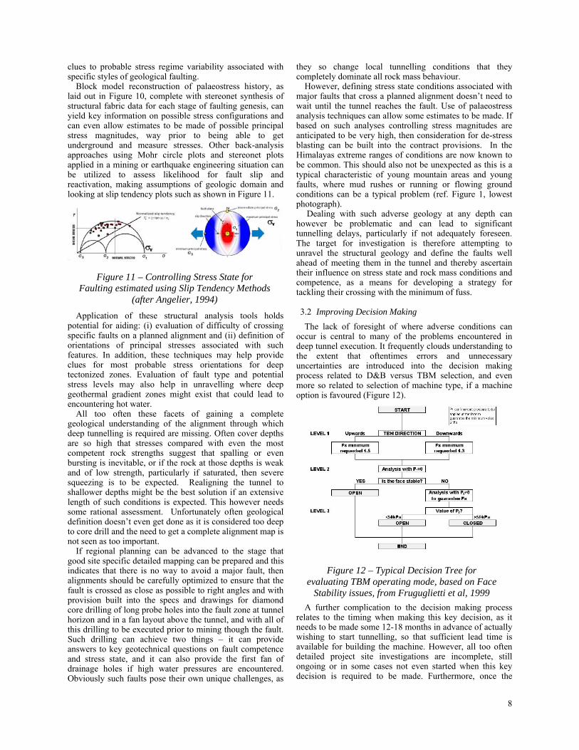
Block model reconstruction of palaeostress history, as laid out in Figure 10, complete with stereonet synthesis of structural fabric data for each stage of faulting genesis, can yield key information on possible stress configurations and can even allow estimates to be made of possible principal stress magnitudes, way prior to being able to get underground and measure stresses. Other back-analysis approaches using Mohr circle plots and stereonet plots applied in a mining or earthquake engineering situation can be utilized to assess likelihood for fault slip and reactivation, making assumptions of geologic domain and looking at slip tendency plots such as shown in Figure 11.
Application of these structural analysis tools holds potential for aiding: (i) evaluation of difficulty of crossing specific faults on a planned alignment and (ii) definition of orientations of principal stresses associated with such features. In addition, these techniques may help provide clues for most probable stress orientations for deep tectonized zones. Evaluation of fault type and potential stress levels may also help in unravelling where deep geothermal gradient zones might exist that could lead to encountering hot water.
All too often these facets of gaining a complete geological understanding of the alignment through which deep tunnelling is required are missing. Often cover depths are so high that stresses compared with even the most competent rock strengths suggest that spalling or even bursting is inevitable, or if the rock at those depths is weak and of low strength, particularly if saturated, then severe squeezing is to be expected. Realigning the tunnel to shallower depths might be the best solution if an extensive length of such conditions is expected. This however needs some rational assessment. Unfortunately often geological definition doesn’t even get done as it is considered too deep to core drill and the need to get a complete alignment map is not seen as too important.
If regional planning can be advanced to the stage that good site specific detailed mapping can be prepared and this indicates that there is no way to avoid a major fault, then alignments should be carefully optimized to ensure that the fault is crossed as close as possible to right angles and with provision built into the specs and drawings for diamond core drilling of long probe holes into the fault zone at tunnel horizon and in a fan layout above the tunnel, and with all of this drilling to be executed prior to mining though the fault. Such drilling can achieve two things – it can provide answers to key geotechnical questions on fault competence and stress state, and it can also provide the first fan of drainage holes if high water pressures are encountered. Obviously such faults pose their own unique challenges, as
they so change local tunnelling conditions that they completely dominate all rock mass behaviour.
However, defining stress state conditions associated with major faults that cross a planned alignment doesn’t need to wait until the tunnel reaches the fault. Use of palaeostress analysis techniques can allow some estimates to be made. If based on such analyses controlling stress magnitudes are anticipated to be very high, then consideration for de-stress blasting can be built into the contract provisions. In the Himalayas extreme ranges of conditions are now known to be common. This should also not be unexpected as this is a typical characteristic of young mountain areas and young faults, where mud rushes or running or flowing ground conditions can be a typical problem (ref. Figure 1, lowest photograph).
Dealing with such adverse geology at any depth can however be problematic and can lead to significant tunnelling delays, particularly if not adequately foreseen. The target for investigation is therefore attempting to unravel the structural geology and define the faults well ahead of meeting them in the tunnel and thereby ascertain their influence on stress state and rock mass conditions and competence, as a means for developing a strategy for tackling their crossing with the minimum of fuss.
3.2 Improving Decision Making
The lack of foresight of where adverse conditions can occur is central to many of the problems encountered in deep tunnel execution. It frequently clouds understanding to the extent that oftentimes errors and unnecessary uncertainties are introduced into the decision making process related to D&B versus TBM selection, and even more so related to selection of machine type, if a machine option is favoured (Figure 12).
A further complication to the decision making process relates to the timing when making this key decision, as it needs to be made some 12-18 months in advance of actually wishing to start tunnelling, so that sufficient lead time is available for building the machine. However, all too often detailed project site investigations are incomplete, still ongoing or in some cases not even started when this key decision is required to be made. Furthermore, once the
Figure 12 – Typical Decision Tree for evaluating TBM operating mode, based on Face
Stability issues, from Fruguglietti et al, 1999
Figure 11 – Controlling Stress State for Faulting estimated using Slip Tendency Methods
(after Angelier, 1994)
9
contract is finally awarded to the contractor, generally after a long and arduous tendering process, always insufficient time and/or funds have been allocated to allow the contractor any opportunity for additional customized exploration to support his own excavation technology selection procedures before initiating equipment procurement. In nearly all projects the tender exploration data, which can be exceedingly variable in quality, is the only basis on which to make equipment selection. These added constraints create yet more levels of totally unnecessary risk to an already difficult decision.
3.3 Project Risk
Unlike many civil geotechnical tunnel works, for subways and such like, because of the depth and length of many deep mountain tunnels in the Himalayas investigating the tunnel alignment is a challenge all of its own. In urban areas tunnel investigations frequently end up with boreholes on 50m centres or closer along the alignment. This is impractical if not cost prohibitive for deep mountain tunnels. As a result very heavy reliance needs to be placed on gaining as best as possible an appreciation of geological conditions at depth and along the alignment.
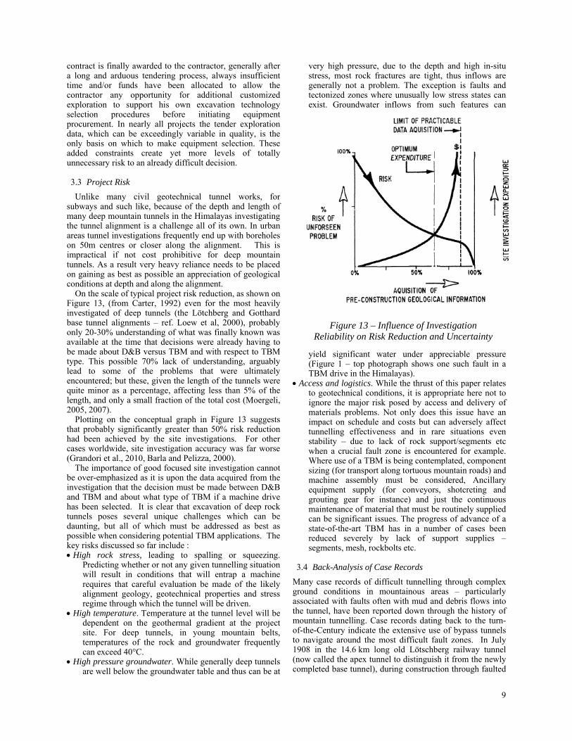
On the scale of typical project risk reduction, as shown on Figure 13, (from Carter, 1992) even for the most heavily investigated of deep tunnels (the Lötchberg and Gotthard base tunnel alignments – ref. Loew et al, 2000), probably only 20-30% understanding of what was finally known was available at the time that decisions were already having to be made about D&B versus TBM and with respect to TBM type. This possible 70% lack of understanding, arguably lead to some of the problems that were ultimately encountered; but these, given the length of the tunnels were quite minor as a percentage, affecting less than 5% of the length, and only a small fraction of the total cost (Moergeli, 2005, 2007).
Plotting on the conceptual graph in Figure 13 suggests that probably significantly greater than 50% risk reduction had been achieved by the site investigations. For other cases worldwide, site investigation accuracy was far worse (Grandori et al., 2010, Barla and Pelizza, 2000).
The importance of good focused site investigation cannot be over-emphasized as it is upon the data acquired from the investigation that the decision must be made between D&B and TBM and about what type of TBM if a machine drive has been selected. It is clear that excavation of deep rock tunnels poses several unique challenges which can be daunting, but all of which must be addressed as best as possible when considering potential TBM applications. The key risks discussed so far include : High rock stress, leading to spalling or squeezing.
Predicting whether or not any given tunnelling situation will result in conditions that will entrap a machine requires that careful evaluation be made of the likely alignment geology, geotechnical properties and stress regime through which the tunnel will be driven.
High temperature. Temperature at the tunnel level will be dependent on the geothermal gradient at the project site. For deep tunnels, in young mountain belts, temperatures of the rock and groundwater frequently can exceed 40°C.
High pressure groundwater. While generally deep tunnels are well below the groundwater table and thus can be at
very high pressure, due to the depth and high in-situ stress, most rock fractures are tight, thus inflows are generally not a problem. The exception is faults and tectonized zones where unusually low stress states can exist. Groundwater inflows from such features can
yield significant water under appreciable pressure (Figure 1 – top photograph shows one such fault in a TBM drive in the Himalayas).
Access and logistics. While the thrust of this paper relates to geotechnical conditions, it is appropriate here not to ignore the major risk posed by access and delivery of materials problems. Not only does this issue have an impact on schedule and costs but can adversely affect tunnelling effectiveness and in rare situations even stability – due to lack of rock support/segments etc when a crucial fault zone is encountered for example. Where use of a TBM is being contemplated, component sizing (for transport along tortuous mountain roads) and machine assembly must be considered, Ancillary equipment supply (for conveyors, shotcreting and grouting gear for instance) and just the continuous maintenance of material that must be routinely supplied can be significant issues. The progress of advance of a state-of-the-art TBM has in a number of cases been reduced severely by lack of support supplies – segments, mesh, rockbolts etc.
3.4 Back-Analysis of Case Records
Many case records of difficult tunnelling through complex ground conditions in mountainous areas – particularly associated with faults often with mud and debris flows into the tunnel, have been reported down through the history of mountain tunnelling. Case records dating back to the turn-of-the-Century indicate the extensive use of bypass tunnels to navigate around the most difficult fault zones. In July 1908 in the 14.6 km long old Lötschberg railway tunnel (now called the apex tunnel to distinguish it from the newly completed base tunnel), during construction through faulted
Figure 13 – Influence of Investigation Reliability on Risk Reduction and Uncertainty

10
ground a section collapsed, killing 25. The collapsed section was reportedly beyond repair, so a bypass tunnel was driven around the site of the disaster. Few collapses these days end with fatalities, especially where TBM’s are employed, but the magnitude of today’s inrushes and collapses are none the less dramatic, and the need for bypass tunnels remains, with several recent examples evident within both D&B and TBM driven tunnels. One recent classic case, exactly 100 years on from the Lötschberg apex tunnel collapse, and which also necessitated a by-pass drift, occurred on the Gibe II project in Ethiopia. In this case significant multiple mudflow events occurred initially burying a state-of-the-art Universal Double Shield machine until it could be extricated and refurbished (Figure 14).
In this case, at the end of October 2006, the TBM was pushed back more than 60cm as consequence of the sudden extrusion and collapse of the tunnel face against the cutterhead and the front shield of the TBM. Monitoring records from the event indicated that the tunnel face pushed back the TBM at approximately 40-60 mm/hour. The TBM head and leading shield layout were also displaced laterally by more than 40 cm. (Figure 14 right side inset diagram). As a consequence, severe damage occurred to the shields, the cylinders and the last 7 segment rings.
Although the DSU Compact system of this machine had been designed to operate in three modes, these ground conditions were more adverse than the worst case design assumptions: The three envisaged design configurations were:– Mode (1) for hard rock – basically a conventional gripper telescopic mode. In this mode, the TBM advances by thrusting off the side grippers in the rear shield and extending the main thrust cylinders. Contemporary with the excavation, rock bolts are installed as per requirement and design. At the end of a TBM stroke the stabilizers and auxiliary grippers placed in the front shield are expanded and the main thrust cylinders are used for pulling the rear shield forward. Mode (2) for weak rock – using an extra (Auxiliary) telescopic arrangement. The TBM in this
configuration advances by thrusting off the side grippers in the rear shield and extending the main thrust cylinders. Contemporary with the excavation, prefabricated steel sets are installed within the tail fingers. At the end of TBM stroke the stabilizers and auxiliary grippers placed in the front shield are expanded and the rear shield is advanced thrusting off the steel sets using the auxiliary thrust; and Mode (3) envisaged for Fault zones – basically a single shield mode The TBM advances in this configuration all together like an articulated single shield by thrusting off the auxiliary cylinders. At the end of excavation prefabricated steel sets would be envisaged to be installed within the tail fingers. The drive was successfully completed after the TBM had been extracted and rebuilt, with a number of innovative modifications (Figure 15).
As is evident from Figure 14 the scope of the problem when it was encountered was completely undefined. More than 30 long exploratory drillholes and significant exploratory and bypass drifting was completed in order to develop a scheme that could successfully advance the TBM though this difficult zone. Arguably this again poses the same typical question – could the problems have been foreseen by regular probe drilling? and if so what could have been done differently than in this actual situation? Obviously, if one had been forewarned then the likelihood
Figure 14 – Extent of Exploratory Drilling to define fault zone characteristics following mudrush inflows on Gibe II Project in order to free trapped TBM (from Grandori et al, 2011). Note – mudflow induced disruption of machine configuration & top heading and chamber excavation and support layouts
Figure 15 – Modifications to TBM Cutterhead to incorporate larger curvature and overcut to
help cope with mud-push effects

11
would be that the machine wouldn’t have been buried – with much reduced delays and consequences. Again it appears that much like almost all of the citable cases these collapses and/or inrushes came as an almost complete surprise. In fact, review of many documented cases suggests that for a large percentage no forecasting was available before the collapse because the area was not investigated; often because cover was too great or access difficulties prevented drilling to the tunnel horizon or because of contractual arrangements – “turn key” and EPC contracts gaining a notoriety in recent years for their lack of comprehensiveness of investigation compared with most typical owner-administered contracts of earlier years, even before the advent of Geotechnical Baseline Reports and Project Specific Risk Registers.
Sometimes direct causative information can be identified, one common factor being delayed progress through difficult ground. The Amsteg fault zone collapse and entrapment of the TBM on the west drive of the Alp Base Tunnel, whereas the TBM on the east drive passed through the zone with only minimal difficulty, (Moergeli, 2005, Downing et al, 2007) can be partially attributed to rate of advance issues. Several recent TBM problems that have developed in bad ground in Himalayan tunnels also initiated when production advance was delayed as a result of holiday and/or maintenance shutdowns.
It is an amazing fact though, that even after the tunnelling industry has executed hundreds of kilometres of tunnels and endured numerous collapses, the majority of which have lead to signifcant delays and often serious cost implications for the projects, inadequate forecasting of future conditions still emerges as a clear common thread for almost all cases.
3.5 Application of Methodology Specific Classifications
This raises the question of whether currently available tools and techniques are appropriate and credible enough to actually aid prediction. While significant progress has been achieved in characterizing rock mass conditions through classifications, such as Q, RMR, GSI and even through subset varietal classifications specifically directed to TBM performance prediction, (Barton’s QTBM and Bieniawki’s RME, McFeat-Smith’s IMS and others), classification use (and abuse, particularly for contractual purposes) for prediction has been mixed at best and frequently erroneous.
For Himalayan type mountain conditions, can such classifications be hoped to aid forecasting sufficient to evaluate TBM viability and appropriateness. While there a great tendency these days to rely on using classifications to “fill-in” gaps in available data, the weight of evidence from surprises suggests that this could be foolhardy without basic data improvement.
Use of classifications without an adequate database of site specific reference information should be avoided, certainly for design and later project stage evaluation.
Even for D&B drives where the rock can almost always be observed at least for a short time at the face, there is still significant debate ongoing on the accuracy of classifications as a predictive measure (Carter, 2010; Palmström and Broch, 2006, Sapigni et al, 2002, Zhao, 2007). As a consequence, while they can be routinely applied at the design and tender stage and as a means for mapping D&B or TBM tunnels as they are advanced, they must not be used alone as all too often gaining an understanding of the basic
geology of the tunnel alignment gets lost in the process of rigorously attempting to apply such classifications.
While the main objectives of all classification systems as suggested by Milne et al.(1998) has been (i) to quantify the intrinsic properties of the rock mass based on past experience; (ii) to investigate the behaviour of the rock mass under the action of external loadings; (iii) to select appropriate support; and (iv) to estimate rock mass properties, unfortunately they have in recent years been stretched somewhat beyond these original simple aims and basic geology appreciation has been lost in the process. This is even more so the case with some of the extension systems attempting to categorize TBM advance and penetration rates. As all these systems are based on a certain range of case histories, being experience based, they each have limitations and these in turn lead to some inherent shortcomings, but these often seem to get forgotten. As suggested by Stille and Palmström; 2003, Palmström and Broch, 2006, Palmström and Stille, 2006 and summarized by Zhao, 2007, five prime issues need consideration, especially if any classification system is intended to be used as a sole means for "design":
a) Suitability: Rock mass classification systems do not cover all rock mass conditions, especially, in heterogeneous and poor ground conditions, thus classification systems may provide misleading results;
b) Inaccuracy: In general, empirical methods only yield averaged values of specific parameters, while actual values may be significantly different;
c) Validity: Classifications cannot of themselves substitute for proper design, primarily because they largely ignore actual mechanisms of rock mass behaviour. Defining support solely on the basis of a rock mass classification number, for instance, can often lead to erroneous layouts, simply because the user is tending to ignore the mechanisms actually controlling the behaviour of the supported rockmass and the details of the construction process that determines the boundary conditions of the problem, (Cording 1984; Milne et al. 1998; Schubert et al. 2001); and finally,
d) Reliability: Classifications should be considered for what they are – excellent aids to design, but not of themselves a “design” Always the degree of safety achieved by their use for “design” remains an unknown. In applying them to assess machine viability there is even greater danger of their not being appropriate for a given situation because there is no database of that experience in their basis.
While these comments largely concern reliability of support layouts and density when “designed” using the various classification systems, many of the same problems exist with respect to using these same systems or extensions of them for estimating TBM performance. This is a useful goal, but as shown by extensive studies that have been carried out to try to set up a relationship between rock mass quality (RSR, RMR, IMS, Q and QTBM) and TBM penetration rate (Barla, 2000; Sapigni et al., 2002; Ribacchi and Fazio, 2005; Innaurato et al., 1991; Alber, 1996 and 2000; McFeat-Smith, 1999; Grandori et al., 1995; Barton, 2000; Gong and Zhao, 2007; Gong et al., 2006, 2007), there remains wide scatter in accuracy for the currently available classifications. Zhao, 2007 notes that while the results show that with an increase in rock mass quality, penetration rates

12
generally decrease, it is noted however, that for very poor rock, this correlation breaks down, as poor rock quality does not of itself facilitate increased penetration rate.
Barton, 1990 has recognized this in the two diagrams presented in Figure 16. Both show advance rate - which is a function not only of penetration rate but also of logistics of support installation and mining difficulties. As is clear maximums are reached in moderate quality rockmasses and rates are much slower at the extreme ends of the rock competence scale, irrespective of depth conditions. These graphs arguably could look different for deep tunnels where stress complications leading to squeezing and/or spalling could further compromise the plotted advance rates.
These rate charts could also differ appreciably if they were plotted just for faulted ground, with or without water. In fact, achieving reasonable excavation rates through faults is not only a challenge for prediction, it is the principal TBM design challenge; and this is where only application of innovative ideas will achieve improvement in solving current difficulties with crossing such geological structures.
Faults are the problem ground which TBM's must cross without being trapped and buried, which support methods must be flexible enough to combat, and, which need to be adequately characterized. This latter goal can usually only be achieved based on a metre by metre characterization using current geomechanics classifications as ground conditions from one side to another of a fault zone typically vary by several rock classes (Figure 17). This is doubly the case at great depth as the weaker gouge zones might even be subject to squeeze or if in a destressed state with significant water, they will flow. Margin zones, and even fault cores, can sometimes be pervasively rehealed with quartz or carbonates or other mineral assemblages (sometimes in a
stockwork geometry) such that the zone now behaves extremely brittlely and is thus subject to spalling or even bursting. The Sungra Fault at Nathpa Jhakri, (Carter et al, 2008b) and the Parbati current face zone (Panthi, 2010) are excellent examples of faults with such major variability. These are the sorts of ground conditions that challenge any tunnelling, and mechanized tunneling in particular.
For the TBM designer this extreme variability of ground behaviour over just a few metres length of the tunnel poses a major challenge. Achieving progress and yet installing sufficient yielding support, while not halting advance which might allow trapping of the machine requires a next generation of innovation in machine capability and flexibility. Because bad faults typically comprise a
significant width of extremely complex and variable ground conditions they constitute a unique challenge. Experience from the Himalayas, the Andes and the Alps has shown that these really bad faults can only be successfully mined through in the very worst cases with full jet grouted umbrella arch support, with installation of lattice girders or yielding steel arch sets with heavy application of fibre or mesh-reinforced shotcrete, in many cases with half or multishell NATM tunnel geometry in order to eventually get out to full tunnel width and height. A machine equipped to install only segments, would be completely overwhelmed by such conditions, irrespective of the available thrust and competence of the machine design. Deere, 2007 cites the most common methodologies for crossing faults as involving (1) pre-drainage; (2) forward grouting; (3) pre-reinforcement, and (4) pilot drift “hand” mining. All of these have been used for both D&B and TBM tunnel crossings of faults; with variable degrees of success in preventing catastrophic collapses.
4 ANATOMY OF COLLAPSES
Almost all collapses occur associated with faults, and particularly where significant water inflow is encountered. Collapse cases are known from all types of tunnel drive – from both shielded and open machine excavated drives and from D&B and NATM excavated tunnels also. Collapse propensity depends on rock quality, presence or absence of water and applied support pressure – at the face and above
Figure 16 – Advance and Penetration Rate estimates for TBM’s and some comparative
D&B rates (from Barton, 2005, 2009)
Figure 17 – Typical conditions within brittle fault / deformation zones (left diagram, Deere,
2007, right diagram, Munier et al., 2003)

13
the crown. If rock quality at the face and above the crown is too poor to be self supporting and rubblized material is freely released into the tunnel face zone it usually creates a cathedral cave-in above the tunnel, (Figure 18) if it doesn’t jam the cutterhead and bury the machine.
Similar instances are cited for the San Pelligrino Tunnel (Figure 19) and for Pinglin (Figure 20).
In each of these cases bad ground necessitated hand mining over the top of the machine. Similar experiences were commonplace on the Guadarrama Tunnel in Spain (Mendana, 2007). Always, the same three complications – water, stress and rockmass competence, continue to control ground behaviour and complicate tunnelling advance when
potential for collapse is high. Characteristically adverse stress slabbing, spalling and/or bursting is generally not a major issue within a fault zone itself. The lead-in margin zones to the fault may be zones of significant spalling distress (Figure 17), but typically the core area of the fault, is not; although it may be subject to squeeze if of low rock competence. Generally, though, it is water that is the bane of the tunneller when traversing adverse fault zones. Encountering significant flow volumes (especially if under high pressure) can turn a bad ground zone into a nightmare with the potential for uncontrolled mudflow inrushes and ravelling induced collapse.
5 OTHER TUNNEL PERFORMANCE OBSERVATIONS
5.1 Bursting and Squeezing Situations
While there are a number of case histories of tunnel construction in overstressed rock using conventional means (drill and blast), there are relatively few case histories of TBM applications in such conditions. The Gotthard Base Tunnel stands out as the most recent and best example of TBM excavation of a deep tunnel in overstressed rock. Most of this tunnel was excavated by TBMs (50 km of the 57 km) The tunnel was subdivided into five sections — Erstfield, Amsteg, Sedrun, Faido and Bodio, with TBM excavation undertaken of all sections except Sedrun which has been just recently completed by conventional means because of anticipated poor rock conditions, the potential for high groundwater inflows and the possibility of adverse ground deformations. This section indeed has experienced significant closure issues, and several kilometres have been excavated using deformable arch support with the HidCon yielding element included in the steel sets. As the magnitudes of convergence have been significant this section would have been a challenge for the unshielded hard rock TBMs utilized on the other sections of the tunnel, again confirming a wise early decision based on good site investigation practice.
In the Amsteg and Faido sections, which were excavated beneath cover of 2,200 m and 2,500 m respectively the TBM tunnels were driven slightly larger (9.4 m diameter compared with 8.8 m diameter for the adjacent Bodio section) as a means to allow for expected closure at these depths, not so much in the gneisses and granites of the Aar
Figure 18 – Hand Mined Top Heading in Caving Ground over initially trapped Double Shield Machine in the Evinos-Mornos Tunnel
(from Grandori, 1995).
Figure 20 – Geometry of Characteristic Ground Collapse around TBM head as encountered in
Pinglin Tunnels (from Shen et al., 1999).
Figure 19 – Pilot Tunnel Methods utilized for negotiating complex Faulted ground on the San Pellegrino Tunnel (Frasnadello section) (from
Barla & Pelizza, 2000).

14
Massif but more so in the gneisses and schists of the Gotthard Massif, and particularly associated with the Intschi Fault Zone. Rock support through all this section consisted of systematic rock bolts, steel mesh and shotcrete installed behind the cutterhead. Yielding support with sliding steel sets were installed in some areas as required. The main challenge for the TBM’s apart from the faults was the bulking entrapment problem created by continual spalling include a rock bursting zone in the Faido section (Eberhardt, 2001; Schmalz, 2006; Diederichs, 2007), with one event at a measured magnitude of 2.4 (Richter Scale), thought to have been caused by stress re-distribution associated with the adjacent tunnel drive. This burst was reported to have resulted in only minor damage to the tunnel lining. In June 2005, the west tunnel TBM on the Amsteg Section encountered a 50 m fault zone with “hydrothermally decomposed granite” at a depth of 2,200 m. This zone stalled TBM progress for a period of five months with one machine, the other drive passed through the same fault with minimal problems. The west tunnel drive was restarted following completion of an adit from the east tunnel, from which extensive grouting was carried out and then a pre-excavation heading was developed through the fault zone through which the TBM was traversed, and then restarted.
In contrast to the Gotthard Base Tunnels, where TBM difficulties mostly have been associated with competent rock and spalling issues, arguably not of the severity of the Olmos experience (Lewis, 2009), the Yacambu Irrigation project in Venezuela probably represents the most adverse weak rock conditions where TBM’s have been tried. This project consists of a 4.8 m diameter, 24 km long tunnel, which was to be driven using a variety of methods, including TBMs.
In 1975, two shielded TBMs (short single shields) were launched, with ground support consisting of steel ribs and shotcrete. In 1979, one of the TBMs was engulfed by squeezing ground during a holiday break. Ground movement was particularly severe at the invert. Portions of the TBM were cut into pieces and removed. The second TBM was abandoned in a side drift shortly afterwards. Two further TBMs were brought to site, specially designed to deal with the Bocono Fault (a major Andean plate structure). Due to funding constraints, these TBMs were not started and all remaining construction was carried out by drill and blast or with roadheaders. The most severe squeezing conditions occurred in sheared, graphitic phyllite with UCS values as low as 1 MPa with cover of approximately 600 m. In these areas, strain values in excess of 30% were observed.
In the Evinos-Mornos project in Greece, constructed between 1992 and 1995, four TBMs were used to excavate a 30 km long, 4 m diameter water supply tunnel under cover of up to 1,300 m. It was reported that more than 30% of the tunnel was in very poor quality rock (RMR of Class V) and 650 m of this tunnel was in squeezing ground (Grandori, 1995). The project is of interest since both open and shielded TBMs were used. For ground support, the open TBMs used steel ribs and lagging in the poor ground. In squeezing ground, shotcrete was applied immediately behind the cutterhead. Some steel sets deformed under the applied loads, thus requiring replacement. A final cast in place concrete liner was placed in sections of the tunnel excavated with the open TBMs. Two double-shield TBMs
were also used on the project and utilized a concrete segmental lining erected immediately behind the shield. It was reported that all machines coped with the ground reasonably well, with the open TBMs performing better in the good ground and poorer in the poor ground. Average advance rates of 15 and 21 m/day were reported for the two open TBMs and 17 and 26 m/day for the two double-shield TBMs. Squeezing ground movements of up to 15 cm were reported 1 m from the face. Several collapses occurred and necessitated top heading drifts to be completed by hand methods over the machines to free them (Figure 20).
Of particular note from all the available literature and field data on collapses and on entrapment problems is that in almost all of the tunnels where squeezing phenomena were observed significant magnitudes of squeeze did not occur immediately behind the tunnel face but only after the TBM had passed and rock support or precast or segmented linings had been installed. In these cases the effect of squeezing can be considered more of a lining design issue than a TBM design issue.
Extreme and fast squeezing is known in special geological situations, mainly because of rock formation competence and the tectonic state and overburden cover magnitude,. Again the experience of the Evinos-Mornos tunnel drive is very encouraging in this sense since very high squeezing pressures were overcome without major stoppages while on the contrary the collapsing of the tunnel face create much bigger problems. 5.2 Groundwater influence
If water bearing faults are encountered during tunnelling under high cover, then not only is the magnitude of inflow a problem, but grouting and sealing issues are also problematic as grouting is notoriously difficult against high inflow pressures. A fully sealed “can” such as in a closed face shield machine cannot provide full enough control to prevent ingress to the machine, as pressures will far exceed the maximum possible with current brush and tail seal technology. The onus is therefore on grouting to reduce hydraulic conductivity, and on forward probing to detect adverse water conditions ahead of the machine, so that drainage or other remedial measures can be undertaken. For the Lötschberg Base Tunnel, the karstified and fractured limestones and marls of the Doldenhorn Nappe, which were encountered in the tunnel over a length of 3.2 km, were anticipated to be subject to high groundwater inflows (pressures up to 60 bar) (Pesendorfer, 2006).
As a result, this section of the alignment was intensively explored prior to main tunnelling with an exploratory adit and a series of long geotechnical drilholes, and during tunnel construction with long (300 m) horizontal cored boreholes, drilled from the main tunnel face. Based on single and cross-hole tests two major highly transmissive zones were identified (one with approximate inflows of 50 L/s under a pressure of 35 bar, which was grouted with >50 tonnes of cement through a pattern of more than 50 holes, and the second with approximately 30 L/s under a pressure of 52 bars which was determined to be treatable using drainage). Based on this hydrogeologic exploration program, tunnelling and grouting costs were kept to a minimum and remediation of the zone was completed six months ahead of schedule.

15
Similar programs of long angled exploratory drilling were undertaken for the Piora section yielding significant water under pressure within the sugar grained dolomite rock conditions known to exist in that area (Figure 21 shows the fan drill layouts in section). As is evident quite and extensive program of drilling was undertaken, with the intent to determine the geology and geotechnics of the zone. This drilling established that the main tunnels could be routed to pass beneath the worst problem area, thus avoiding the water inflow worries – again providing an excellent example of the significant effectiveness of wise expenditure on early detailed investigation (ref. Carter, 1992, 1995 for examples of similar application of effective risk minimization approaches to investigation to improve engineering judgment). For the Arrowhead Tunnels in the US, realignment around expected water bearing zones by contrast wasn’t a favoured or viable option. Accordingly significant ongoing water problems were faced, but because of ample pre-evaluation forward probing, drainage and grouting measures and procedures were developed to combat the high water inflows while still advancing the TBM’s. (Fulchner, 2008). All these cases highlight how effective pre-examination can significantly help in arriving at an optimum solution for tunnelling whilst also reducing significantly the chance of tunnelling surprises. 5.3 Mechanical design issues
Forecasting the magnitude of convergence and closure and the likelihood of water and faults has been the focus of this paper. Other factors are also of importance for the developing a machine concept (e.g., rock hardness and abrasivity; structural fabric, and the necessity of designing rock reinforcement installation and backup systems that will efficiently carry out rock support and muck handling). These are not dealt with here, nor are other issues relating to details of machine fabrication, muck bucket geometry, roof and sidewall support – bolts and shotcrete versus segments or other lining form, the issues surrounding gripper deign to avoid bearing failure in weak rock, the effects of thrust on cutter design, issues around system design, shields versus open, and EPB or even slurry use at the face to provide positive pressure to resist collapse potential. The pros and cons of proper cutterhead design merits a complete paper on its own, as do the issues surrounding tapered TBM shield body shapes, longitudinal gaps between gauge cutters and roof support on an open machine or the leading edge of the shield on a shield machine. The industry now seems to be adopting variable speed cutterhead drives for most situations. These are essential in loose ground conditions, both for limiting the disturbance of fractured rock and for controlling muck flow into the head when ravelling ground is encountered.
5.4 Rock Support Considerations
From the viewpoint of tunnel support, a TBM driven tunnel has a number of advantages over a drill and blast tunnel. Rock mass damage is lessened for a machine driven tunnel, leading to reduced requirements for ground support. Also, where high stresses may be an issue, a circular tunnel is generally more stable than a horseshoe shaped tunnel with a flat floor. For an open TBM, conventional tunnel support (rock bolts, wire mesh, shotcrete or ring beams) is a
flexible system generally allowing adjustments to be made to suit most geological conditions. With an open TBM, support can be installed relatively close to the face, which is particularly important in poor or squeezing ground. Open TBMs can be designed to allow installation of rock bolts, ring beams and shotcrete immediately behind the cutterhead, and ahead of the grippers, as adopted for the Gotthard tunnels. Conventional support can be designed to be ductile and allow tunnel deformation without collapse or loss of support integrity. In contrast, conventional shielded TBMs do not allow for early installation of support, when the machine could be operating in an open more and typically do not allow for adjustment of rock support to suit varying conditions. A shield machine however can be adapted to supply positive faced pressure (in typically an EPB configuration with an Archimedes screw mucking system rather than buckets and a conveyor.
The innovative concept of the All-Condition-Tunneller (ACT) – Figure 22 is that it attempts to pull all of the different mechanical elements together into one. As shown in the figure, the rear shield can be pulled back allowing rock support to be installed to the face. This creates some of the same safety problems as an open machine in spalling and bursting ground, where projectiles can be dangerous to
Figure 22 – Robbin’s ACT Hybrid machine incorporating facets of DS-EPB-and Main Beam
Open Concept Designs (from Home,2010), showing trailing shield retracted for bolting
Figure 21 – Layout of Fan Drillhole patterns utilized to explore sugar-grained Dolomite
Piora Zone (Loew et al, 2000)

16
workers, as such events occur violently without warning. The incorporation of McNally slats as per the Olmos machine in combination with automatic placement of mesh in combination with reinforcement appears to hold promise for mitigating this type of hazard
Machine design to cope with potentially squeezing and flowing ground is also advancing with development of tapered shields and machines that allow rapid shifting of propulsion and face support modes (EPM-DS-Open). More innovative solution is likely needed on being able to provide some immediate degree of overcut and perhaps a significant umbrella arch overdrill capability so that large convergence can be tolerated. Moderate overcut can be achieved right now by mounting a number of gage cutters on hydraulically adjustable swinging arms, with the cutter mechanically locked in position to assure a rigid load path. Allowable movements as much as 100 mm, can be achieved in increments of 25 mm from the nominal bore.
6 CONCLUSIONS
In recent years increasing use has been made of TBMs for the excavation of deep rock tunnels. The largely successful use of TBMs for the deep Alp Base Tunnels provides a good case record demonstrating the suitability of the chosen
style of open TBMs in all but the most severe of squeezing conditions. Although there have been some notable failures of other TBMs elsewhere in deep rock tunnels, the great majority of recent applications using new purpose built machines have been successful, and the increasing body of experience is providing the necessary information on ground behaviour and machine design required to extend their use to the more difficult mountain zones of the world with the highest active stress states.
The table and diagrams in Figure 23 highlight some of the most important characteristics of problematic ground from the viewpoint of TBM design; and highlight areas where future innovation to solve some of the outstanding rock mechanics problems of deep TBM drives may be achievable. Firstly, almost always squeezing ground tends to be essentially dry. This does not mean literally "dry" - what an essentially dry state implies is that the rockmass is of such intrinsically low permeability that free water inflow is negligible. This is also often the situation for burst-prone ground at the other end of the rock competence scale. Again, at this high competence end of the scale rock mass permeability is low, and hence inflows to a tunnel will also be low. By contrast, it is almost a prerequisite that for high water inflows and/or for mobile ground inrushes (mud and/or sand etc) stresses in the rockmass in the vicinity of the inflow site must be low or at maximum, moderate. This
Figure 23: Characteristics of Problem Ground Conditions with respect to three controlling criteria – Water, Stress and Rock Mass Quality and Competence

17
is not to say that the water or mud will not be under considerable pressure, but that spalling, bursting or squeezing conditions will not prevail. As such TBM operations may be perhaps more appropriately balanced to dry or wet state operating modes.
The diagrams in the lower right of the Figure show in isometric configuration the two states - wet on the lower plane (Jw < 0.33) and - dry on the upper plane (Jw > 0.75) with the various forms of problematic ground indicated within various regions on the rock quality versus stress state plots for the two conditions respectively.
The ternary diagram on the lower left side of the diagram plots the dry state conditions in an analogous manner, omitting the third axis of the plot shown in Figure 9, for clarity. As such only a single value of Jw is utilized. Figure 9 by contrast is arranged on the basis that when one adds water to the equation, resulting conditions are almost always worse, such that as ground conditions deteriorate a point on the plot moves closer and closer to the chart apex.
This holds promise as a convenient approach for aiding evaluation of expected ground conditions as a basis for refining and improving TBM designs to accommodate the expected range of ground behaviour along a given alignment. Using the ternary diagram and the spreadsheet methods outlined earlier, as planning aids the potential extent of squeezing, spalling or bursting ground for any proposed alignment might potentially be better investigated and understood. All too often, as indicated by the case records an incomplete understanding of possible ground conditions and likely ground behaviour during tunnelling has proved detrimental and lead to costly and time consuming machine modifications underground, slow progress and in extreme cases, loss of a TBM.
Embarking on better planned, more extensive investigations holds the key to removing much current uncertainty regarding TBM effectiveness in certain rock conditions along any particular alignment. Understanding rockmass behaviour and how different machines cope in different ground conditions is also key – as this insight will stimulate innovative thought towards next generation improvements in machine design
REFERENCES Alber M 1996. Prediction of penetration and utilization for
hard rock TBMs. Barla G. (ed.), Eurock’96, Balkema, Rotterdam, pp.721-725.
Alber M 2000. Advance rates of hard rock TBMs and their effects on project economics. Tunnelling and Underground Space Technology, Vol.15, pp.55-64.
Alber, M. 1988. Design of High Speed TBM Drives. Proc. Canadian Tunneling; pp.181–187. (From selected papers from the 15th Can. Tunneling Conference, Vancouver).
Alptransit website. www.alptransit.ch Anagnostou G 2007 Practical consequences of the time-
dependency of ground behaviour for tunnelling. Proc RETC pp 225-265
Anagnostou G. and Kovari; K., 1996: "Face stability conditions with Earth-Pressure-Balanced Shields". Tunneling and Underground Space Technology, Vol. 11, No.2. pp. 165-173.
Anagnostou, G. 1993. A model for swelling rock in tunneling, Rock Mechanics and Rock Engineering, 26, 307–331.
Anagnostou, G., and Kovári K., 1997. Face stabilization in closed shield tunneling. Rapid Excavation and Tunnel Construction, Las Vegas, 549–558.
Anagnostou, G., and Kovári, K. 1994. The Face Stability of Slurry-Shield-Driven Tunnels. Tunnelling and Underground Space Technology, Vol. 9, No. 2, pp. 165-174.
Angelier, J., 1994, Fault Slip Analysis and Palaeostress Reconstruction. In: Hancock, P.L., (Ed) Continental Deformation, Peragmon Press, Oxford, pp. 53-100.
Babendererde, L. 2001 High Speed Hardrock Tunnelling Preconditions for a successful BOT project. Proc, AITES-ITA World Tunnel Congress, Milan, Italy, 7pp
Babendererde, S. 1991. Kritische Betrachtungen zum Einsatz von Hydroschilden. In Berichte des Int. Symp. Sicherheit und Risiken bei Untertagebauwerken (eds R.Fechtig & K. Kovári), 47–51 (in German).
Barla G 2000. Lessons learnt from the excavation of a large diameter TBM tunnel in complex hydrogeological conditions. Geo2000, Keynote Lecture, pp.82.
Barla G. and Barla M. 1998. Tunnelling in difficult conditions. Int. Conf. on Hydro Power Development in Himalayas, Shimla (India), 20-22 April, 19 pages.
Barla G., and Pelizza S., 2000, TBM tunnelling in difficult conditions, GeoEng2000, Int. Conf. Geotech & Geological Eng. Melbourne,Australia), 20pp
Barla, G., 2009 Innovative tunneling construction method to cope with squeezing at the Saint Martin La Porte access adit (Lyon-Turin Base Tunnel). Proc. Eurock09, Dubrovnik, Croatia pp 15-24, CRC Press/Balkema
Barton N 2000. TBM Tunnelling in jointed and faulted rock. Balkema, Rotterdam, pp.172.
Barton N, Lien R, Lunde J (1974). Engineering classification of rock mass for the design of tunnel support. Norwegian Geotechnical Institute, Vol.106, pp.1-48.
Barton, N. 1976. Recent Experiences with the Q-system of Tunnel Support Design. Proc. Symp. on Exploration for Rock Engineering. Johannesburg, pp. 107–117.
Barton, N. 1993. Updating the Q-System for NMT. Proc. Int. Symp. On Sprayed Concrete, Fragernes.
Barton. N. 2009. TBM prognoses in hard rock with faults using QTBM methods. Keynote lecture, Inst. of Min. Metall. International Tunnelling Conf., Hong Kong.
Bhalla S, Yang YW, Zhao J, Soh CK (2005). Structural health monitoring of underground facilities – technological issues and challenges. Tunnelling and Underground Space Technology, Vol.20, pp.487-500.
Bieniawski von Preinl ZT, Tamames BC, Fernandez JMG, Hernandez MA 2006. Rock mass excavatability (RME) indicator: new way to selecting the optimum tunnel construction method. ITA-AITES 2006, Seoul, pp.1-6.
Bieniawski Z.T. 1973. Engineering classification of jointed rock masses. Civil Engineer in South Africa, pp.335-343.
Bieniawski, Z.T. 1976. Rock mass classification in Rock Engineering. Proc. Symp., Exploration for Rock Engineering, Vol. 1: pp.97-106. CapeTown: Balkema.
Broch E 1999. Rock tunnelling. Open Session: past, present and future of Tunnelling, ITA-AITES 1999, Oslo, pp.22-30.

18
Carter, T.G., 1990. Use of Forward Probe Coring Methods and Remote Sensing for Investigation of Geological Conditions Ahead of Drill and Blast and TBM Tunnel Drivages, Proc. ISRM International Symposium on Static and Dynamic Considerations in Rock Engineering, Mbabane, Swaziland, pp. 91–101.
Carter, T.G., 1992 Prediction and Uncertainties in Geological Engineering and Rock Mass Characterization Assessment. Proc. 4th Italian Rock Mechanics Conference, Torino. pp. 1.1 - 1.22.
Carter, T.G., 1995 Effective Site Investigation - A Necessity for Hydropower Design, Proc. Conf. on Design and Construction of Underground Structures, New Delhi, India, pp. 3-19.
Carter, T.G., 2010 Applicability of Classifications for Tunnelling - Valuable for Improving Insight, but Problematic for Contractual Support Definition or Final Design, 10pp Proc. WTC 2010, 36th ITA Congress, Vancouver, Paper 00401 Session 6c 19th May
Carter, T.G., Cottrell, B.E., Carvalho, J.L. and Steed C.M. 2008a Logistic Regression improvements to the Scaled Span Method for dimensioning Surface Crown Pillars over Civil or Mining Openings Proc. 42nd US Rock Mechanics Symposium and 2nd Can-US Rock Symp. San Francisco. Paper 08-282 10pp
Carter, T.G., Diederichs, M.S. and Carvalho, J.L., 2008b. Application of modified Hoek-Brown transition relationships for assessing strength and post yield behaviour at both ends of the rock competence scale. The Journal of the Southern African Institute of Mining and Metallurgy, Vol. 108: pp 325-338.
Carter, T.G., Steels, D., Dhillon H.S., & Brophy D., 2005. Difficulties of Tunneling under High Cover in Mountainous Regions, Int’l. AFTES Cong., Tunnelling for a Sustainable Europe, Chambery, pp. 349–358.
Cording E 1984. State of the art: rock tunnelling. In Tunnelling in Soil and Rock (Lo KY, editor), Proc Geotech’84, pp.77-106.
Cornejo L., 1989: Instability at the face: its repercussion for tunneling technology". Tunnels & Tunneling, April, pp. 69-74.
Deere, D.W., 2007 Tunnelling through Mountain Faults. Proc. Rapid Excavation and Tunnelling Conference, Toronto, Canada. pp280-287
Diederichs, M. S., T. Carter and D. Martin. 2010 Practical Rock Spall Prediction in Tunnels, in Tunnel Vision Towards 2020 (Proc.ITA - AITES World Tunnellng Congress, Vancouver, May). Paper No. fin00517 8pp
Diederichs, M.S. 2007. Mechanistic Validation and Practical Application of Damage and Spalling Prediction Criteria for Deep Tunnel;ing. 2003 Can. Geotech. Colloq. Can. Geotech. Journal.
Downing, B., Beddoes, R., Moss A. and Dowden, P. 2007 Use of Tunnel Boring Machines at Depth: Extending the Limits. Proc. Rapid Excavation and Tunnelling Conference, Toronto, Canada. pp 1131-1142
Eberhardt, E. 2001. Numerical Modelling of Three-Dimension Stress Rotation ahead of an Advancing Tunnel Face. Int. J. Rock mech. Min. Sci. Vol. 38, pp. 499–518.
Einstein HH, Dudt J-P, Halabe VB, Descoeudres F 1992. Decision Aids in Tunnelling: principle and practical application. Swiss Federal Transportation Dept
Einstein, H.H. and Bobet, A. 1997. Mechanized Tunneling in Squeezing Rock - From Basic Thoughts to Continuous Tunneling. Tunnels for People, Golser, Hinkel & Schubert (eds), Balkema, Rotterdam.
Fasching A. and Bofer, M. 1997. A Tunnel Under the Andes. Tunnels and Tunneling.
Fernandez,E., 2005 Double Shields to Build the High Speed Railway Network in Spain, RETC Proceedings, Chapter 36, pp. 470-484.
Fogli, E., and Grandori, R., from Seli - TBM specialist contractors, 2011 Pers.Comm. – wrt TBM application.
Fruguglietti, A., Guglielmetti, V., Grasso, P. Carrieri, G.and Xu, S., 1999. Selection of the right TBM to excavate weathered rocks and soils. Proceedings of the World Tunnel Congress, Oslo, pp. 839-847.
Fulcher, B., Bell M., and Knut Garshol, 2008 Pre-Excavation Drilling and Grouting for Water Control and Ground Improvement in Highly Variable Ground Conditions at the Arrowhead Tunnels Project RETC Proceedings pp. 749-765.
Ghaboussi, J., and G. Gioda 1977. On the time-dependent effects in advancing tunnels. Int. J. Num. & Anal. Meth. Geomech., Vol. 1, 249–269.
Girmscheid G, Schexnayder C 2003. Tunnel boring machine. Practice Periodical on Structural Design and Construction, Vol.(8)3, pp.150-163.
Girmscheid G, Schexnayder C 2003. Tunnel boring machine. Practice Periodical on Structural Design and Construction, Vol.8(3), pp.150-163.
Gong QM, Jiao YY, Zhao J 2006. Numerical modelling of the effects of joint spacing on rock fragmentation by TBM cutters. Tunnelling and Underground Space Technology, Vol.21, pp.46-55.
Gong QM, Zhao J 2007. Influence of rock brittleness on TBM penetration rate in Singapore granite. Tunnelling and Underground Space Technology,
Gong QM, Zhao J, Jiang YS 2007. In situ TBM penetration tests and rock mass boreability analysis in hard rock tunnels. Tunnelling and Underground Space Technology
Goricki A, Schubert W, Riedmueller G 2004). New developments for the design and construction of tunnels in complex rock masses. Sinorock 2004 Symposium, Int. J. Rock. Mech. Min. Sci. Vol.41, No.3, CD-ROM.
Grandori R and Pellegrini, L. 2007 Tunneling Through Faults in Volcanic Rocks for the Construction of the La Joya Project (Costa Rica), Proc. RETC pp. 266-279.
Grandori R, Sem M, Lembo-Fazio A, Ribacchi R 1995. Tunnelling by double shield TBM in the Hong Kong granite. Proceedings of 8th Int Cong for Rock Mechanics, Vol.1, pp.569-574.
Grandori, R. et al., 1995. Construction of a 30 km Long Hydraulic Tunnel in Less than Three Years Under the Most Adverse Geological Conditions. Rapid Excavation and Tunneling Conference.
Grandori, R., and F. Antonini 1994. Double shield TBM excavation technique—Recent experiences and future development. Felsbau 12 (1994) Nr. 6: 490–494.
Grimscheid G, Schexnayder C 2002. Drill and blast tunnelling practise. Practice Periodical on Structural Design and Construction, Vol.7(3), pp.125-133.
Grimstad, E. and Barton, N. 1995. Rock Mass Classification and the Use of NMT in India. Proc. Int. Conf. on Design

19
and Construction of Underground Structures, New Delhi, India.
Gutridge R.D., and Rendini, D., 2005 Design and Construction of the Shoal Creek Raw Water Intake at Lake Lanier, RETC Proceedings, Chapter 88, pp. 1115-1125.
Herrenknecht M, and Bappler K 2003. Segmental concrete lining design and installation. Soft Ground and Hard Rock Mechanical Tunneling. Technology Seminar, Colorado School of Mines, pp.4.
Herrenknecht M, and Rehm U 2003. Hardrock technology. Soft Ground and Hard Rock Mechanical Tunneling Technology Seminar, Colorado School of Mines, pp.20.
Herrenknecht M. and Maidl U., 1995 Applyng foam for an EPB shield drive in Valencia, Tunnel n. 5/95. pp. 10-19.
Hoek E, Marinos P, Benissi M 1998. Applicability of the Geological Strength Index (GSI) classification for very weak and sheared rock masses. The case of the Athens Schist Formation. Bull. Eng. Geol. Env. Vol.57(2),pp.151-160.
Hoek, E and Guevara, R., 2009. Overcoming squeezing in the Yacambú-Quibor tunnel, Venezuela. Rock Mech, and Rock Engineering, Vol. 42, No. 2, 389 - 418.
Hoek, E. 1999. Putting numbers to geology — an engineer’s viewpoint. Q. Jnl Eng. Geol. & Hydrogeol. Vol. 32, no. 1, pp. 1–19 (19)
Hoek, E. 2000. Big Tunnels in Bad Rock, The Terzaghi lecture—presented at the ASCE Civil Engineering Conf., Seattle, October 18–21, 2000.
Hoek, E. and Brown, E.T. 1988. The Hoek-Brown failure criterion—a 1988 update. Proc.15th Canadian Rock Mech. Symp. (ed. J.H. Curran), Toronto: Civil Engineering Dept., University of Toronto, pp. 31–38.
Hoek, E. and Marinos, P. 2000. Predicting Tunnel Squeezing. Tunnels and Tunneling International, Part 1—November 2000, Part 2—December.
Home, L, of the Robbins Co., TBM manufacturers, 2011 Pers.Comm. – wrt TBM application.
Hutchinson, D.J. and Diederichs, M.S. 1996 Cablebolting in Underground Mines Published by BiTech Publishers Ltd. Richmond, British Columbia, Canada 406pp
Hutchinson, D.J. and Diederichs, M.S. 1996 Cablebolting in Underground Mines Published by BiTech Publishers Ltd. Richmond, British Columbia, Canada 406pp
Innaurato N, Mancini R, Rondena E, Zaninetti A 1991. Forcasting and effective TBM performance in a rapid excavation of a tunnel in Italy. Proc 7th Int Cong on Rock Mechanics, pp.1009-1014.
Jancsecz S. and Steiner W, 1994 Face support for a large Mix-Shield in heterogeneous ground conditions, Tunnelling 94, London.
Kanayasu S., Kubota I., Shikibu N., 1995 Stability of face during shield tunneling - A survey on Japanese shield tunnelling. Underground Construction in soft ground. Balkema, Rotterdam, pp. 337 -343.
Khademi-Hamidi, J., Bejari, H.Shahriar, K., Rezai, B., Rostami, J and 2008 Assessment of Ground Squeezing and Ground Pressure Imposed on TBM Shield Proc. 12th Int. Conf. International Association for Computer Methods and Advances in Geomechanics (IACMAG) Goa, India, pp.3907-3914
Khademi-Hamidi, J., Shahriar, K., Rezai, B., Rostami, J and Bejari, H. 2009 Risk assessment based selection of rock
TBM for adverse geological conditions using Fuzzy-AHP. Bulletin of Engineering Geology and the Environment Volume 69, Number 4, 523-532, DOI: 10.1007/s10064-009-0260-8
Kirsten, H.A.D., 1988. Discussion Contribution relating to the Norwegian Geotechnical Institute Q System. In Rock Classification Systems for Engineering Purposes. ASTM STP 984, ed. Kirkaldie, L., Philadelphia, pp. 86–88.
Kocbay, J, Marence, M and Linortner, A, 2009. Hydropower plant Ermenek / Turkey, Pressure tunnel - design and construction. Proceedings of WTC 2009, ITA, Budapest, Hungary, 13pp
Larsen, Ø., Fossen, H., Langeland, K. & Pedersen, R.B., 2003, Kinematics and timing of polyphase post-Caledonian deformation in the Bergen area, SW Norway. Norwegian Journal of Geology, vol. 83, pp.149-165. ISSN 029-196X.
Leca E. and Dormieux L., 1990 Upper and lower bound solutions for the face stability of shallow circular tunnel in frictional material Geotechnique. Vol. 40. n. 4. pp. 581-606.
Lewis, W. 2009. Construccion de Tuneles Transandinos en la Cordillera de Los Andes. Proc. Taller Internacional de Tuneles y Obras Subterranes. Bogota,
Loew, S., Ziegler, H-K, and Keller, F 2000 Alptransit: Engineering Geology of the World's Longest Tunnel System, Proc GeoEng2000 An International Conference on Geotechnical & Geological Engineering. Technomic Publishing Co., Melbourne, Australia, pp. 927-930.
Maidl B., Herrenknecht M, Anheuser L., 1996: Mechanised Shield Tunneling, Ernst&Sohn, Berlin.
Maidl U. and Cordes H., 2003 Active earth pressure with foam. Proceedings of the ITA World Tunnelling Congress, Amsterdam, pp.791-791
Marinos, P. and Hoek, E., 2000, GSI: A geologically friendly tool for rock mass strength estimation, Proc. GeoEng2000 Conference, Melbourne, p. 1422-1442
McFeat-Smith I 1999. Mechanised tunnelling for Asia. Workshop Mannal, Organized by IMS Tunnel Consultancy.
Mendana, F., 2007 Guadarrama Tunnel Construction with Double Shield TBMS, Proc RETC pp. 1079-1093.
Milne D, Hadjigeorgiou J, Pakalnis R 1998. Rock mass characterization for underground hard rock mines. Tunnelling and Underground Space Technology, Vol.13(4), pp.383-391.
Mitani, S., Iwai, T. and Isahai, H. 1987. Relations between conditions of rock mass and TBM’s feasibility. Proc. 6th ISRM congress, Montreal. 1:701-704 Rotterdam: Balkema.
Moergeli, A. 2005a, Risk management in action —controlling difficult ground by Innovation, Rapid Excavation and Tunneling Conference.
Moergeli, A. 2005b, Presentation of Risk management in action — controlling difficult ground by innovation, Rapid Excavation and Tunneling Conference.
Munier, R., Stenberg, L., Stanfors, R., Milnes, A.G., Hermanson, J. and Triumf, C.A., 2003, Geological Site Descriptive Model: A strategy for the model development during site investigations. Svensk Kambranslehantering AB, Swedish Nuclear Fuel and Waste Management Co.
Neil, D.M., Harami, K.Y., Hanson, D.R., Morino, A., Kalamaras, G.S., & Grasso P. 1999. State-of-the-art 3D
20
tomography techniques for geotechnical evaluation of site and alignment conditions during tunnelling. World Tunnel Congress ITA. Oslo, 29 May–3 June 1999, pp. 121–128.
Nord G., 2006. The latest development within the drill and blast tunnelling. Proceedings of Österreichischer Tunneltag, Salzburg, pp.67-75.
Palmstrom A (1995). RMi-a rock mass characterization system for rock engineering purposes. PhD Thesis, University of Oslo, 400pp.
Palmström A and Stille H (2006). Ground behaviour and rock engineering tools for underground excavations. Tunnelling and Underground Space Technology (in press).
Palmström A, and Broch E., 2006. Use and misuse of rock mass classification systems with particular reference to the Q-system. Tunnelling and Underground Space Technology, Vol.21, pp.575-593.
Palmström A. (2000): Recent developments in rock support estimates by the RMi. Journal of Rock Mechanics and Tunnelling Technology, Vol.6, pp.1-9.
Palmström A., (2005) Measurements of and correlations between block size and rock quality designation. Tunnelling & Undergr Space Tech; 20(4): pp362–377
Panthi, K.K., 2009, Appropriateness of open TBM tunnelling in the Himalaya – A case study Proc. Eurock09, Dubrovnik, Croatia pp815-819, CRC Press/Balkema
Peila, D & Pelizza, S, 2003 Ground Probing and Treatments in Rock TBM Tunnels to overcome Limiting Conditions. J. Mining Science. Vol. 42, No 2. pp 602-619
Pesendorfer, M. 2006; Hydrogeologic Exploration and Tunneling in a Karstified and Fractured Limestone Aquifer (Lötschberg Base Tunnel, Switzerland). PhD Thesis, Swiss Federal Institute of Technology (ETH) Zürich. Diss. ETH Nr. 16724
Ramoni M. & Anagnostou G. 2008: TBM drives in squeezing rock - Shield-rock interaction; Building underground for the future; AFTES International Congress Monaco, Montecarlo; 163-172; Edition specifique Limonest.
Ribacchi R, 1994: Recenti orientamenti nella progettazione statica delle gallerie. Atti XVIII Convegno Nazionale di Geotecnica. Quinto Ciclo di Conferenze di Meccanica ed Ingegneria delle Rocce, Torino, No. 15, pp. 1-15.
Ribacchi R, Lembo-Fazio A (2005). Influence of rock mass parameters on the performance of a TBM in a gneissic formation (Varzo Tunnel). Rock Mech. Rock Eng. Vol.38 (2), pp.105-127.
Roby J., Willis, D., Carollo, B.S.,and Askilsrud, O.G. 2008, Coping with difficult ground and 2000 m of cover in Peru. Proc. WTC 2008, Agra, India
Russo G 2003 Evaluating the required face-support pressure in EPBS advance mode. Proc Gallerie e Grande Opere Sotterranee n.71 pp27-32
Sapigni M, Berti M, Bethaz E, Busillo A, Cardone G (2002). TBM performance estimation using rock mass classifications. International Journal of Rock Mechanics & Mining Sciences, Vol.39, pp.771-788.
Sapigni M., Bertib, M., Bethazc, E., Busillod, A. and Cardonee, G. 2002 TBM performance estimation using rock mass classifications International Journal of Rock Mechanics & Mining Sciences 39 pp.771–788
Schmalz, G., DeDomenicis, S.L. 2006. Gotthard Base Tunnel—the worlds longest railway tunnel, in Tunneling
Association of Canada 19th National Conference, September 2006. 1142, 2007 Proc. RETC
Seidenfub T (2006). Collapses in tunnelling. Master thesis, Stuttgart University of Applied Sciences, Swiss Federal Institute of Technolog Lausanne, and international Tunnelling Association, 194pp.
Shen, C.P., Tsai, H.C., Hsieh, Y.S. & Chu, B. 1999. The methodology through adverse geology ahead of Pinglin large TBM. Proc. RETC. Orlando, FL. Hilton & Samuelson (eds).Ch.8: 117-137.Littleton, CO: Soc. for Mining, Metallurgy, and Exploration, Inc.
Shirlaw JN, Hencher S, Zhao J 2000. Invited issue lecture: underground excavations in tropically weathered soils and rocks. Proc. GeoEng2000, Melbourne, Australia.
Singh, B., Jethwa, L.L and Dube, A.K. 1995 A Classification System for Support Pressure in Tunnels and Caverns. J. Rock Mech and Tunneling Technology, Vol. 1, #1, pp. 13–24.
Stille H, and Palmström A 2003. Classification as a tool in rock engineering. Tunnelling and Underground Space Technology, Vol.18, pp.331-345.
Tunnels and Tunnelling 2009 Vol. 46. _30th July, Breakthrough in Ethiopia p11
VanDerPas, Ed. and Alum, R. 1995. “TBM Technology in Deep Underground Copper Mine.” Rapid Excavation and Tunneling Conference.
Verman, M., Carter, T.G., and Babendererde, L., 2011. TBM vs D&B - A Difficult Choice in Mountain Terrain - Some Geotechnical Guidelines; Proc 34th ISRM Congress, Beijing 6pp (in press)
Vigl, L., Jager, M. 1997. Double shield TBM and Open TBM in squeezing rock — a comparison. In International Conference on Tunnels for People, Golser, Hinkel & Schubert (eds), Balkema, Rotterdam.
Vuilleumier F 2006. The Loetschberg base tunnel – first lessons. Proc 2006 China Int Symp High Speed Railway Tunnels, Beijing, China, Nov. 2006, pp.319-326.
Vuilleumier F, Seingre G 2005. The example of Alp transit project Loetschberg base tunnel. ITA/AITES – Training Course, Tunnel Engineering Istanbul-2005, pp.1-9.
Zhao J 2006. The challenge of TBM excavation in rock. Tunnel and Tunnelling International, September 2006, pp.27-29.
Zhao J, Gong QM 2006. Rock mechanics and excavation by tunnel boring machine – issues and challenges. Proc ARMS4.
Zhao J, Gong QM, Eisensten Z., 2007. Tunnelling through a frequently changing and mixed ground: a case history in Singapore. Tunnelling and Underground Space Technology.
Zhao, J., 2007 Tunnelling in Rocks – Present Technology & Future Challenges, Keynote Lecture, WTC Prague - 11pp.