Embed Size (px)
Citation preview
HILUX
Electrical Wiring Diagram
Pub. No. DR114W
NOTICEWhen handling supplemental restraint system components (removal,installation or inspection, etc.), always follow the direction given in the repairmanuals listed above to prevent accidents and supplemental restraintsystem malfunction.
FOREWORD
This wiring diagram manual has been prepared to provide
information on the electrical system of the HILUX.
Applicable models: KUN15, 16, 25, 26 Series
For service specifications and repair procedures of the above
models other than those listed in this manual, refer to the
following manuals;
Manual Name Pub. No. HILUX Repair Manual
HILUX New Car Features
DR172E
NCF271E
All information in this manual is based on the latest product
information at the time of publication. However, specifications
and procedures are subject to change without notice.

2004All rights reserved. This book may not bereproduced or copied, in whole or in part, withoutthe written permission of Toyota MotorCorporation.
1
HILUXELECTRICAL WIRING DIAGRAM
Section Code Page
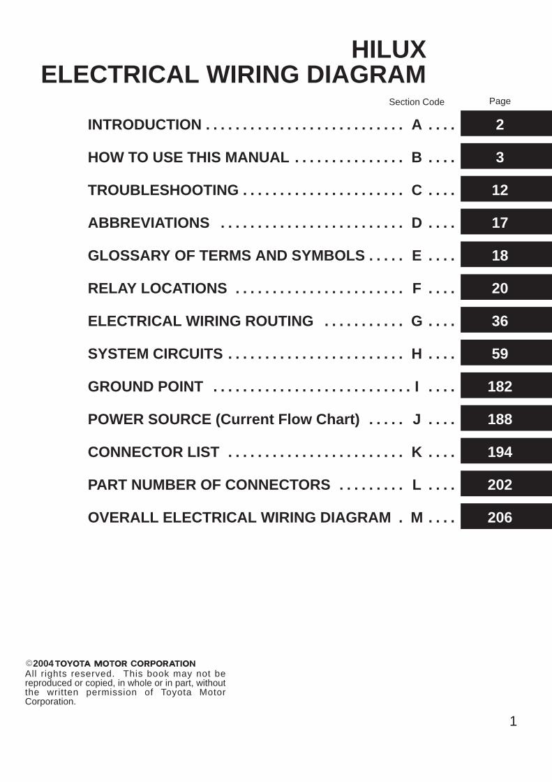
INTRODUCTION A. . . . . . . . . . . . . . . . . . . . . . . . . . . . . . . 2
HOW TO USE THIS MANUAL B. . . . . . . . . . . . . . . . . . . 3
TROUBLESHOOTING C. . . . . . . . . . . . . . . . . . . . . . . . . . 12
ABBREVIATIONS D. . . . . . . . . . . . . . . . . . . . . . . . . . . . . 17
GLOSSARY OF TERMS AND SYMBOLS E. . . . . . . . . 18
RELAY LOCATIONS F. . . . . . . . . . . . . . . . . . . . . . . . . . . 20
ELECTRICAL WIRING ROUTING G. . . . . . . . . . . . . . . 36
SYSTEM CIRCUITS H. . . . . . . . . . . . . . . . . . . . . . . . . . . . 59
GROUND POINT I. . . . . . . . . . . . . . . . . . . . . . . . . . . . . . . 182
POWER SOURCE (Current Flow Chart) J. . . . . . . . . 188
CONNECTOR LIST K. . . . . . . . . . . . . . . . . . . . . . . . . . . . 194
PART NUMBER OF CONNECTORS L. . . . . . . . . . . . . 202
OVERALL ELECTRICAL WIRING DIAGRAM M. . . . . 206
2
A INTRODUCTION
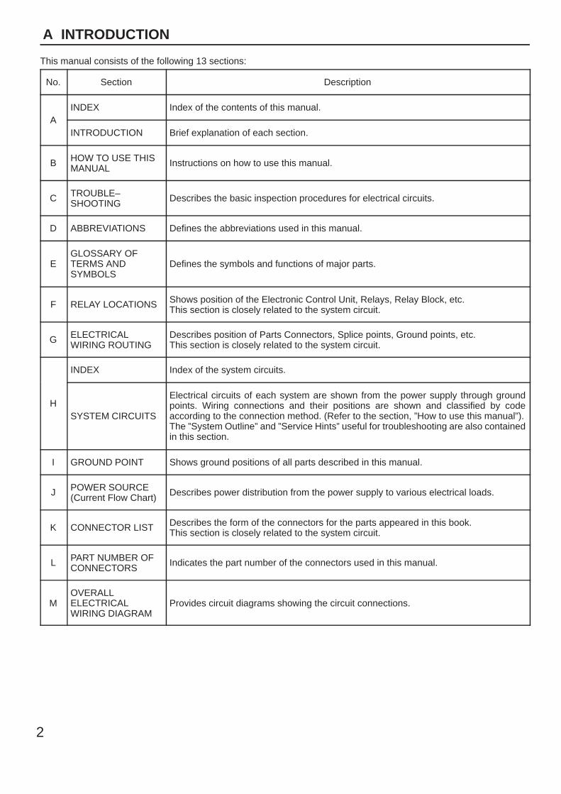
This manual consists of the following 13 sections:
No. Section Description
AINDEX Index of the contents of this manual.
AINTRODUCTION Brief explanation of each section.
B HOW TO USE THISMANUAL Instructions on how to use this manual.
C TROUBLE–SHOOTING Describes the basic inspection procedures for electrical circuits.
D ABBREVIATIONS Defines the abbreviations used in this manual.
EGLOSSARY OFTERMS ANDSYMBOLS
Defines the symbols and functions of major parts.
F RELAY LOCATIONS Shows position of the Electronic Control Unit, Relays, Relay Block, etc.This section is closely related to the system circuit.
G ELECTRICALWIRING ROUTING
Describes position of Parts Connectors, Splice points, Ground points, etc.This section is closely related to the system circuit.
H
INDEX Index of the system circuits.
HSYSTEM CIRCUITS
Electrical circuits of each system are shown from the power supply through groundpoints. Wiring connections and their positions are shown and classified by codeaccording to the connection method. (Refer to the section, ”How to use this manual”).The ”System Outline” and ”Service Hints” useful for troubleshooting are also containedin this section.
I GROUND POINT Shows ground positions of all parts described in this manual.
J POWER SOURCE(Current Flow Chart) Describes power distribution from the power supply to various electrical loads.
K CONNECTOR LIST Describes the form of the connectors for the parts appeared in this book.This section is closely related to the system circuit.
L PART NUMBER OFCONNECTORS Indicates the part number of the connectors used in this manual.
MOVERALLELECTRICALWIRING DIAGRAM
Provides circuit diagrams showing the circuit connections.
3
HOW TO USE THIS MANUAL B
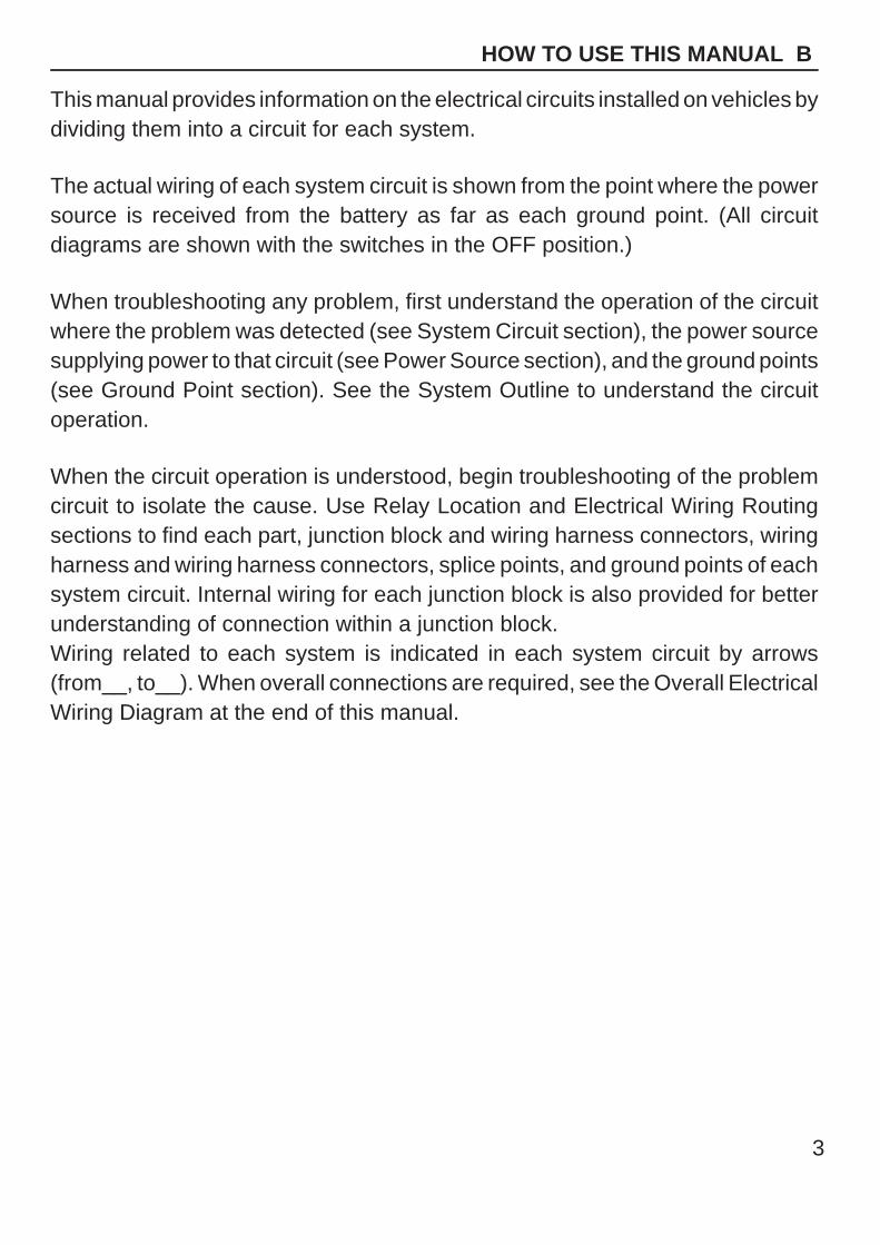
This manual provides information on the electrical circuits installed on vehicles bydividing them into a circuit for each system.
The actual wiring of each system circuit is shown from the point where the powersource is received from the battery as far as each ground point. (All circuitdiagrams are shown with the switches in the OFF position.)
When troubleshooting any problem, first understand the operation of the circuitwhere the problem was detected (see System Circuit section), the power sourcesupplying power to that circuit (see Power Source section), and the ground points(see Ground Point section). See the System Outline to understand the circuitoperation.
When the circuit operation is understood, begin troubleshooting of the problemcircuit to isolate the cause. Use Relay Location and Electrical Wiring Routingsections to find each part, junction block and wiring harness connectors, wiringharness and wiring harness connectors, splice points, and ground points of eachsystem circuit. Internal wiring for each junction block is also provided for betterunderstanding of connection within a junction block.Wiring related to each system is indicated in each system circuit by arrows(from__, to__). When overall connections are required, see the Overall ElectricalWiring Diagram at the end of this manual.
[A]
[B]
[H]
[D]
[F]
[E]
[ I ]
[L]
[M]
[J]
[K]
[G][C]
1
2
IB
IB
3
4
47
2 1 11
13
4
1
2
6
3
1
2
B18
BL
R LG
R
B18G R
3
4
Rea
r C
ombi
natio
n Li
ght R
HR
7
Rea
r C
ombi
natio
n Li
ght L
HR
6
High MountedStop Light
H17
Light Failure Sensor
Stop Light SW
ABS ECU
S 6
CombinationMeter
C 7
BV11 W B
(Shielded)
BV11
I 5G W
IB2
IB1
IE114
BO
50
8L 4
15ASTOP
7.5AGAUGE
From Power Source System (See Page 66)
Stop Light
GR
WB
WB
WB
WB
GB
YG
RL
R
GR
WR
GW
WB
GW
W/G
)
( S/D
)L
L
( ( S/D
)
Sto
p
Sto
p
Rea
r Li
ghts
4
B HOW TO USE THIS MANUAL
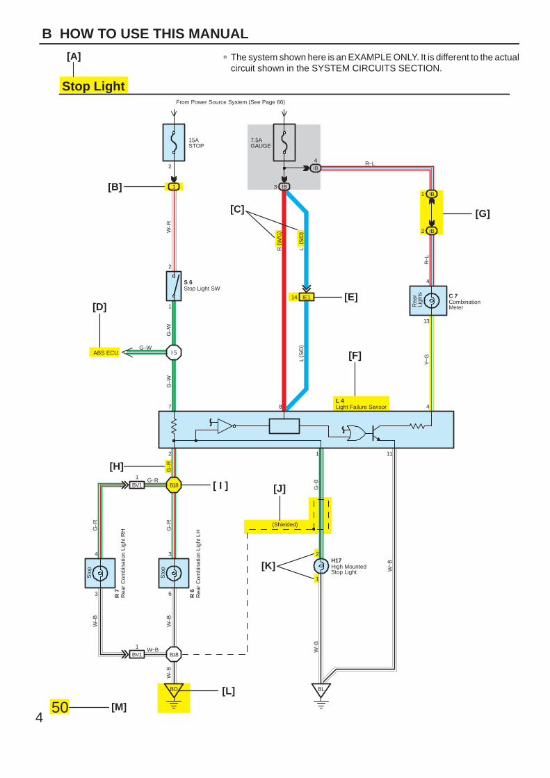
∗ The system shown here is an EXAMPLE ONLY. It is different to the actualcircuit shown in the SYSTEM CIRCUITS SECTION.
5
B
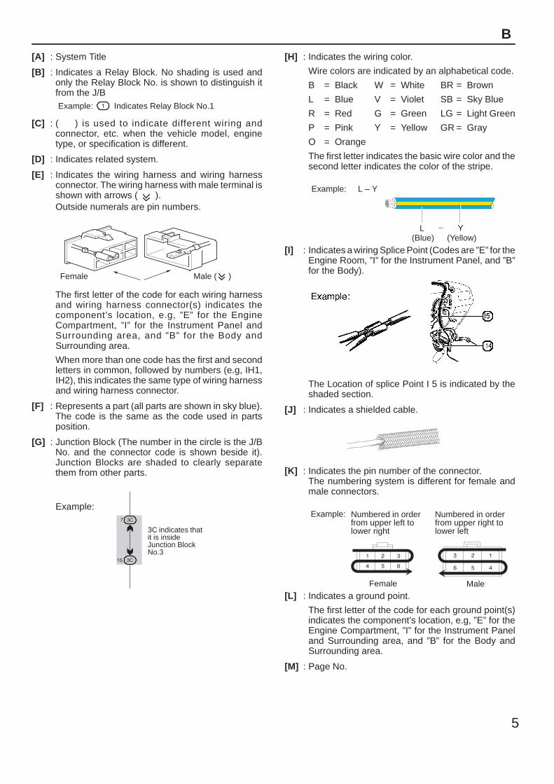
[A] : System Title
[B] : Indicates a Relay Block. No shading is used andonly the Relay Block No. is shown to distinguish itfrom the J/BExample: Indicates Relay Block No.1
[C] : ( ) is used to indicate different wiring andconnector, etc. when the vehicle model, enginetype, or specification is different.
[D] : Indicates related system.
[E] : Indicates the wiring harness and wiring harnessconnector. The wiring harness with male terminal isshown with arrows ( ).Outside numerals are pin numbers.
Female Male ( )
The first letter of the code for each wiring harnessand wiring harness connector(s) indicates thecomponent’s location, e.g, ”E” for the EngineCompartment, ”I” for the Instrument Panel andSurrounding area, and ”B” for the Body andSurrounding area.
When more than one code has the first and secondletters in common, followed by numbers (e.g, IH1,IH2), this indicates the same type of wiring harnessand wiring harness connector.
[F] : Represents a part (all parts are shown in sky blue).The code is the same as the code used in partsposition.
[G] : Junction Block (The number in the circle is the J/BNo. and the connector code is shown beside it).Junction Blocks are shaded to clearly separatethem from other parts.
3C indicates thatit is insideJunction BlockNo.3
Example:
[H] : Indicates the wiring color.
Wire colors are indicated by an alphabetical code.
B = Black W = White BR = Brown
L = Blue V = Violet SB = Sky Blue
R = Red G = Green LG = Light Green
P = Pink Y = Yellow GR = Gray
O = Orange
The first letter indicates the basic wire color and thesecond letter indicates the color of the stripe.
Example: L – Y
L(Blue)
Y(Yellow)
[I] : Indicates a wiring Splice Point (Codes are ”E” for theEngine Room, ”I” for the Instrument Panel, and ”B”for the Body).
The Location of splice Point I 5 is indicated by theshaded section.
[J] : Indicates a shielded cable.
[K] : Indicates the pin number of the connector.The numbering system is different for female andmale connectors.
Example: Numbered in orderfrom upper left tolower right
Numbered in orderfrom upper right tolower left
Female Male
[L] : Indicates a ground point.
The first letter of the code for each ground point(s)indicates the component’s location, e.g, ”E” for theEngine Compartment, ”I” for the Instrument Paneland Surrounding area, and ”B” for the Body andSurrounding area.
[M] : Page No.
[N]
[O]
[P]
[Q]
[R]
[S]
[T]
[U]
6
B HOW TO USE THIS MANUAL
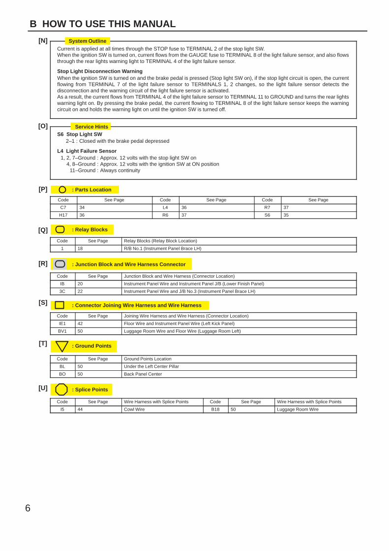
Current is applied at all times through the STOP fuse to TERMINAL 2 of the stop light SW.When the ignition SW is turned on, current flows from the GAUGE fuse to TERMINAL 8 of the light failure sensor, and also flowsthrough the rear lights warning light to TERMINAL 4 of the light failure sensor.
Stop Light Disconnection WarningWhen the ignition SW is turned on and the brake pedal is pressed (Stop light SW on), if the stop light circuit is open, the currentflowing from TERMINAL 7 of the light failure sensor to TERMINALS 1, 2 changes, so the light failure sensor detects thedisconnection and the warning circuit of the light failure sensor is activated.As a result, the current flows from TERMINAL 4 of the light failure sensor to TERMINAL 11 to GROUND and turns the rear lightswarning light on. By pressing the brake pedal, the current flowing to TERMINAL 8 of the light failure sensor keeps the warningcircuit on and holds the warning light on until the ignition SW is turned off.
S6 Stop Light SW2–1 : Closed with the brake pedal depressed
L4 Light Failure Sensor1, 2, 7–Ground : Approx. 12 volts with the stop light SW on
4, 8–Ground : Approx. 12 volts with the ignition SW at ON position11–Ground : Always continuity
: Parts Location
Code See Page Code See Page Code See Page
C7 34 L4 36 R7 37
H17 36 R6 37 S6 35
: Relay Blocks
Code See Page Relay Blocks (Relay Block Location)
1 18 R/B No.1 (Instrument Panel Brace LH)
: Junction Block and Wire Harness Connector
Code See Page Junction Block and Wire Harness (Connector Location)
IB 20 Instrument Panel Wire and Instrument Panel J/B (Lower Finish Panel)
3C 22 Instrument Panel Wire and J/B No.3 (Instrument Panel Brace LH)
: Connector Joining Wire Harness and Wire Harness
Code See Page Joining Wire Harness and Wire Harness (Connector Location)
IE1 42 Floor Wire and Instrument Panel Wire (Left Kick Panel)
BV1 50 Luggage Room Wire and Floor Wire (Luggage Room Left)
: Ground Points
Code See Page Ground Points Location
BL 50 Under the Left Center Pillar
BO 50 Back Panel Center
: Splice Points
Code See Page Wire Harness with Splice Points Code See Page Wire Harness with Splice Points
I5 44 Cowl Wire B18 50 Luggage Room Wire
System Outline
Service Hints
7
B
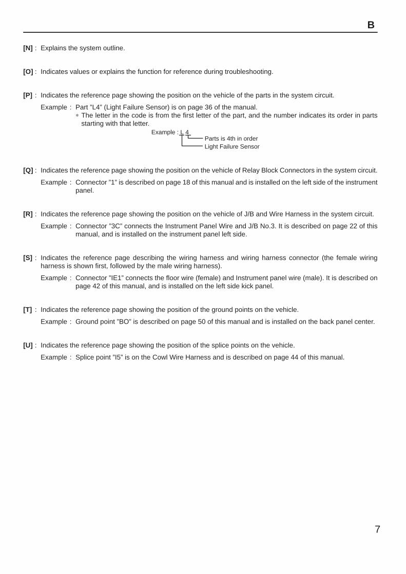
[N] : Explains the system outline.
[O] : Indicates values or explains the function for reference during troubleshooting.
[P] : Indicates the reference page showing the position on the vehicle of the parts in the system circuit.
Example : Part ”L4” (Light Failure Sensor) is on page 36 of the manual.∗ The letter in the code is from the first letter of the part, and the number indicates its order in parts
starting with that letter.Example : L 4
ÁÁ
Parts is 4th in orderLight Failure Sensor
[Q] : Indicates the reference page showing the position on the vehicle of Relay Block Connectors in the system circuit.
Example : Connector ”1” is described on page 18 of this manual and is installed on the left side of the instrumentpanel.
[R] : Indicates the reference page showing the position on the vehicle of J/B and Wire Harness in the system circuit.
Example : Connector ”3C” connects the Instrument Panel Wire and J/B No.3. It is described on page 22 of thismanual, and is installed on the instrument panel left side.
[S] : Indicates the reference page describing the wiring harness and wiring harness connector (the female wiringharness is shown first, followed by the male wiring harness).
Example : Connector ”IE1” connects the floor wire (female) and Instrument panel wire (male). It is described onpage 42 of this manual, and is installed on the left side kick panel.
[T] : Indicates the reference page showing the position of the ground points on the vehicle.
Example : Ground point ”BO” is described on page 50 of this manual and is installed on the back panel center.
[U] : Indicates the reference page showing the position of the splice points on the vehicle.
Example : Splice point ”I5” is on the Cowl Wire Harness and is described on page 44 of this manual.
8
B HOW TO USE THIS MANUAL
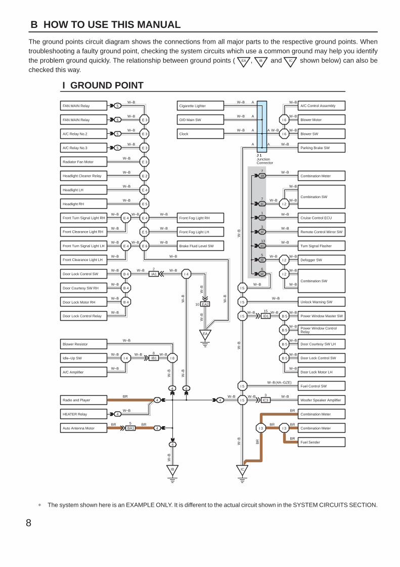
The ground points circuit diagram shows the connections from all major parts to the respective ground points. Whentroubleshooting a faulty ground point, checking the system circuits which use a common ground may help you identifythe problem ground quickly. The relationship between ground points ( EA , IB and IC shown below) can also bechecked this way.
5
5
5
5
4
4
4
4
4BA15
IB18
EA2
ID115
IC33
IA12
E 3
W–B
W–B
W–B
W–B
W–B
W–B
W–B
W–B
W–B W–B
W–B
W–B W–B
W–B
W–B W–B W–B
W–B
W–B
W–B
W–B
W–B
W–B
W–B
W–B W–B W–B
W–B
BR
W–B
BR BR
W–B
W–BW–B
W–B
W–B
W–B
W–BW–B W–B
W–B
W–B
W–B
W–B
W–B
BR
W–B
BRBR
BR
W–B(4A–GZE)
W–BW–B
I 2
I 2
B 5I 5
I 5
I 5
B 5
B 5
B 5
I 5
I 5
I 3I 3
E 3
E 3
E 3
E 2
E 4
E 5
E 4
E 5
E 6E 4
E 4
B 4
EA
I 4
B 4
B 4
I 4 I 8
IB IC
4
4
3E5
3E6
3G13
3F3
3D1
3B7
W–B
W–B
W–BW–B
W–B
W–B
W–B
W–B
W–B
W–B
W–B
W–B
W–B
W–B
W–B
I 6
I 6
I 23C7
10
A
A
A
A
A
A
JunctionConnector
J 1
W–B
W–B
W–B
W–B
BR
W–B
W–B
W–B
W–B
W–B
W–B
I GROUND POINT
FAN MAIN Relay
FAN MAIN Relay
A/C Relay No.2
A/C Relay No.3
Radiator Fan Motor
Headlight Cleaner Relay
Headlight LH
Headlight RH
Front Fog Light LH
Brake Fluid Level SW
Front Fog Light RHFront Turn Signal Light RH
Front Clearance Light RH
Front Turn Signal Light LH
Front Clearance Light LH
Door Lock Control SW
Door Courtesy SW RH
Door Lock Motor RH
Door Lock Control Relay
Blower Resistor
Idle–Up SW
A/C Amplifier
Radio and Player
HEATER Relay
Auto Antenna Motor
A/C Control Assembly
Blower Motor
Blower SW
Parking Brake SW
Combination Meter
Combination SW
Cruise Control ECU
Remote Control Mirror SW
Turn Signal Flasher
Defogger SW
Unlock Warning SW
Power Window Master SW
Power Window ControlRelay
Door Courtesy SW LH
Door Lock Control SW
Door Lock Motor LH
Fuel Control SW
Woofer Speaker Amplifier
Combination Meter
Combination Meter
Fuel Sender
Cigarette Lighter
O/D Main SW
Clock
Combination SW
∗ The system shown here is an EXAMPLE ONLY. It is different to the actual circuit shown in the SYSTEM CIRCUITS SECTION.
9
B
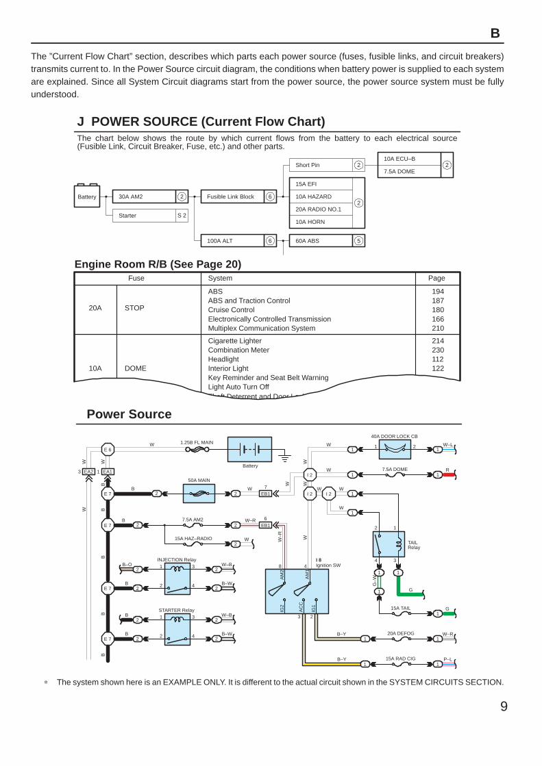
The ”Current Flow Chart” section, describes which parts each power source (fuses, fusible links, and circuit breakers)transmits current to. In the Power Source circuit diagram, the conditions when battery power is supplied to each systemare explained. Since all System Circuit diagrams start from the power source, the power source system must be fullyunderstood.
AC
C
S 2
6
6 5
2
2
2
Battery 30A AM2
Starter
Short Pin
100A ALT
Fusible Link Block
60A ABS
10A ECU–B
7.5A DOME
15A EFI
10A HAZARD
20A RADIO NO.1
10A HORN
20A
10A
Fuse Page
214230112122
194187180166210
ABS
Cigarette LighterCombination Meter
Key Reminder and Seat Belt WarningLight Auto Turn OffTheft Deterrent and Door Lock Control
ABS and Traction ControlCruise ControlElectronically Controlled TransmissionMultiplex Communication System
STOP
System
DOMEHeadlightInterior Light
3 EA2 1 EA1
E 6
E 7
E 7
2
2
22
2
2
2
2
INJECTION Relay
STARTER Relay
B
B
B
B–O 1
1
2
2
3
4
3
4
W–B
W–B
B–W
B–W
E 7
E 7
B
B
W 1.25B FL MAIN
50A MAIN
7.5A AM2
15A HAZ–RADIO
2
2
2
2
2
W
W
EB1
EB1
7
6W–R
I 2 I 2
I 2
W W
W
W
W
1
1
1
1
40A DOOR LOCK CB
7.5A DOME
1 W–L
R
1
1
2
4 3
1
11
1
1 1
1
G
G
W–R
15A TAIL
20A DEFOGB–Y
8 4
3 2
Ignition SWI 8
B–Y1 1
P–L
Battery
15A RAD CIG
2
TAILRelay
Power Source
J POWER SOURCE (Current Flow Chart)
Engine Room R/B (See Page 20)
2
WW
BB
BB
B
W–R
WW
W
G–WA
M2
AM
1
IG2
IG1
W
W
The chart below shows the route by which current flows from the battery to each electrical source(Fusible Link, Circuit Breaker, Fuse, etc.) and other parts.
∗ The system shown here is an EXAMPLE ONLY. It is different to the actual circuit shown in the SYSTEM CIRCUITS SECTION.
Black
[D]
K CONNECTOR LIST
J4 K1 K2 L1
L2 L3 L4 M1 M2 M3
M4 N1 N2 O1 O2
Dark Gray
Gray
Dark GrayBlackGrayGray
A B BA A B C C C
D DD D
AA
AA
AAA A 1
1 2 1 2
1 12 1
2
1 2 36 7 8 9 101112
4 5
71 23 45 6 8
4321
1 2 3 2 3 48 9 105 6
17
1 2 1 1
[A]
[C]
[B]J3
1 2 1 2
6 7 8
1 2A
A
A
AA AA B BA A B C C C
D DD D
I14 I15 I16 J1 J2Dark Gray Gray Black
10
B HOW TO USE THIS MANUAL
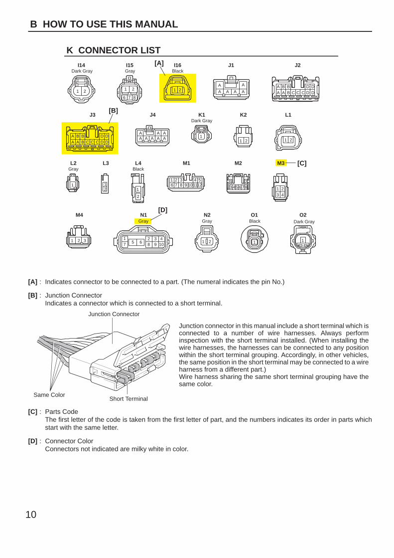
[A] : Indicates connector to be connected to a part. (The numeral indicates the pin No.)
[B] : Junction ConnectorIndicates a connector which is connected to a short terminal.
Junction Connector
Short TerminalSame Color
Junction connector in this manual include a short terminal which isconnected to a number of wire harnesses. Always performinspection with the short terminal installed. (When installing thewire harnesses, the harnesses can be connected to any positionwithin the short terminal grouping. Accordingly, in other vehicles,the same position in the short terminal may be connected to a wireharness from a different part.)Wire harness sharing the same short terminal grouping have thesame color.
[C] : Parts CodeThe first letter of the code is taken from the first letter of part, and the numbers indicates its order in parts whichstart with the same letter.
[D] : Connector ColorConnectors not indicated are milky white in color.
A 1
L PART NUMBER OF CONNECTORS
A/C Ambient Temp. Sensor
Code
90980–11070
Part Number
D 4 Diode (Courtesy)
Code
90980–11608
A 2 A/C Condenser Fan Motor 90980–11237 D 5 Diode (Interior Light) 90980–10962
A 3 A/C Condenser Fan Relay 90980–10940 D 6 Diode (Moon Roof) 90980–11608
A 4 A/C Condenser Fan Resistor 90980–10928
90980–11271
D 7 Door Lock Control Relay 90980–10848
A 5 A/C Magnetic Clutch
90980–11413
D 8 Door Lock Control SW LH90980–11148
A 6 A/T Oil Temp. Sensor
90980–11151
D 9 Door Lock Control SW RH
A 7 ABS Actuator
90980–11009
Door Courtesy SW LH90980–11097
A 8 ABS Actuator
90980–10941
Door Courtesy SW RH
A 9 ABS Speed Sensor Front LH
90980–11002
Door Courtesy SW Front LH
ABS Speed Sensor Front RH
90980–11856
Door Courtesy SW Front RH90980–11156
Airbag Sensor Front LH Door Courtesy SW Rear LH
Airbag Sensor Front RH Door Courtesy SW Rear RH
A10
A11
A12
A13 Airbag Squib 90980–11194 Door Key Lock and Unlock SW LH90980–11170
90980–11070
D10
D11
D12
D13
D14
D15
D16
D17 Door Key Lock and Unlock SW RH
Part NumberPart NamePart Name
[A] [B] [C]
11
B
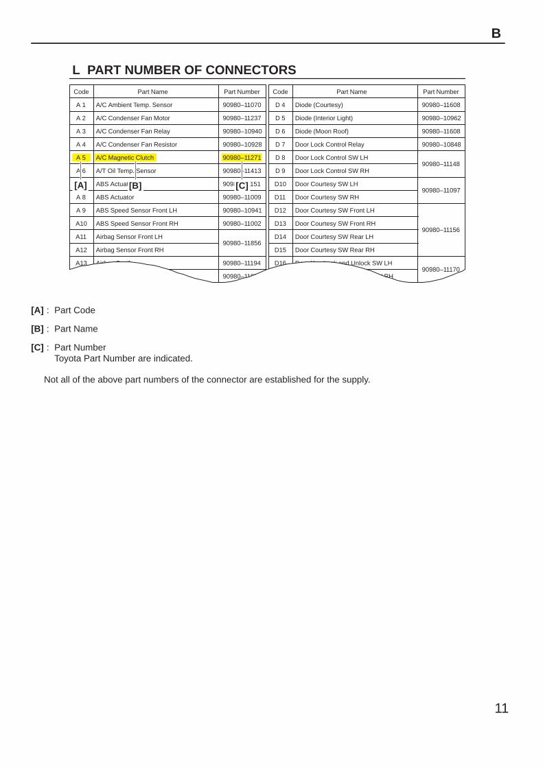
[A] : Part Code
[B] : Part Name
[C] : Part NumberToyota Part Number are indicated.
Not all of the above part numbers of the connector are established for the supply.
To Ignition SWIG Terminal
Fuse
VoltmeterSW 1
Relay
SW 2 Solenoid
[A]
[B]
[C]
Ohmmeter
SW
Ohmmeter
Diode
Digital Type Analog Type
12
C TROUBLESHOOTING
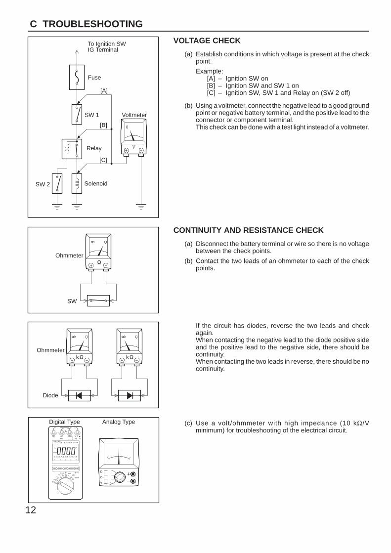
VOLTAGE CHECK
(a) Establish conditions in which voltage is present at the checkpoint.
Example:[A] – Ignition SW on[B] – Ignition SW and SW 1 on[C] – Ignition SW, SW 1 and Relay on (SW 2 off)
(b) Using a voltmeter, connect the negative lead to a good groundpoint or negative battery terminal, and the positive lead to theconnector or component terminal.This check can be done with a test light instead of a voltmeter.
CONTINUITY AND RESISTANCE CHECK
(a) Disconnect the battery terminal or wire so there is no voltagebetween the check points.
(b) Contact the two leads of an ohmmeter to each of the checkpoints.
If the circuit has diodes, reverse the two leads and checkagain.When contacting the negative lead to the diode positive sideand the positive lead to the negative side, there should becontinuity.When contacting the two leads in reverse, there should be nocontinuity.
(c) Use a volt/ohmmeter with high impedance (10 kΩ/Vminimum) for troubleshooting of the electrical circuit.
To Ignition SWIG Terminal
Test Light
RelayLight
SW 2 Solenoid
Disconnect
Short [A]
DisconnectDisconnect
SW 1
Fuse Case
Short [B]
Short [C]
Pull Up
Press Down Press Down
Pull Up
13
C
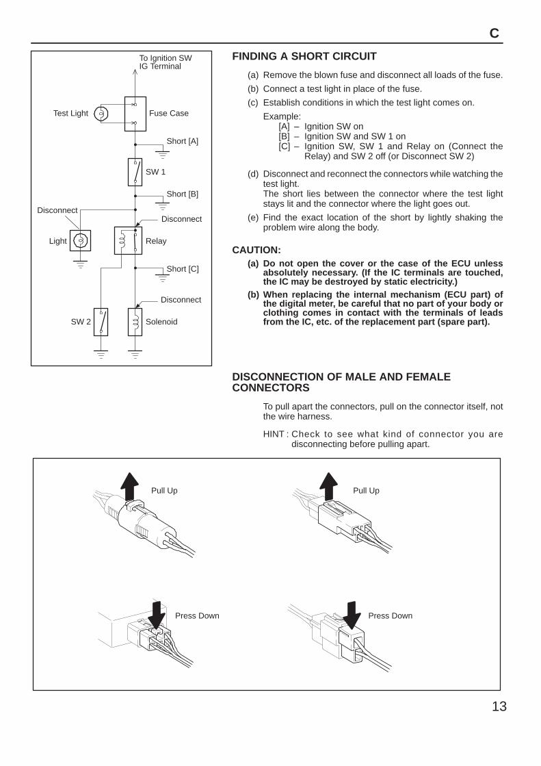
FINDING A SHORT CIRCUIT
(a) Remove the blown fuse and disconnect all loads of the fuse.
(b) Connect a test light in place of the fuse.
(c) Establish conditions in which the test light comes on.
Example:[A] – Ignition SW on[B] – Ignition SW and SW 1 on[C] – Ignition SW, SW 1 and Relay on (Connect the
Relay) and SW 2 off (or Disconnect SW 2)
(d) Disconnect and reconnect the connectors while watching thetest light.The short lies between the connector where the test lightstays lit and the connector where the light goes out.
(e) Find the exact location of the short by lightly shaking theproblem wire along the body.
CAUTION:(a) Do not open the cover or the case of the ECU unless
absolutely necessary. (If the IC terminals are touched,the IC may be destroyed by static electricity.)
(b) When replacing the internal mechanism (ECU part) ofthe digital meter, be careful that no part of your body orclothing comes in contact with the terminals of leadsfrom the IC, etc. of the replacement part (spare part).
DISCONNECTION OF MALE AND FEMALECONNECTORS
To pull apart the connectors, pull on the connector itself, notthe wire harness.
HINT : Check to see what kind of connector you aredisconnecting before pulling apart.
(mm)
Reference:
ToolUpExample:(Case 1)
Terminal Retainer
Terminal Retainer
[Retainer at Full Lock Position]
[Retainer at Temporary Lock Position]
StopperTerminalRetainer
SecondaryLocking Device
Example:(Case 2)
14
C TROUBLESHOOTING
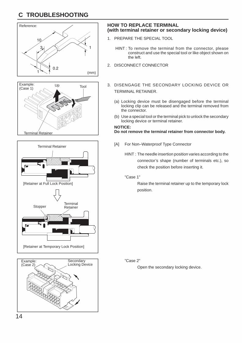
HOW TO REPLACE TERMINAL(with terminal retainer or secondary locking device)
1. PREPARE THE SPECIAL TOOL
HINT : To remove the terminal from the connector, pleaseconstruct and use the special tool or like object shown onthe left.
2. DISCONNECT CONNECTOR
3. DISENGAGE THE SECONDARY LOCKING DEVICE OR
TERMINAL RETAINER.
(a) Locking device must be disengaged before the terminallocking clip can be released and the terminal removed fromthe connector.
(b) Use a special tool or the terminal pick to unlock the secondarylocking device or terminal retainer.
NOTICE:Do not remove the terminal retainer from connector body.
[A] For Non–Waterproof Type Connector
HINT : The needle insertion position varies according to the
connector’s shape (number of terminals etc.), so
check the position before inserting it.
”Case 1”
Raise the terminal retainer up to the temporary lock
position.
”Case 2”
Open the secondary locking device.
ToolTab
Tab
TerminalRetainer
Access Hole( Mark)
Tool
Tool
[Female]
Example:
[Male]
(Case 1)
[Male] [Female]
Retainerat Full Lock Position
Retainerat Temporary Lock Position
Terminal Retainer
[Male] Press Down [Female]Press Down
ToolTool
Example:(Case 2)
15
C
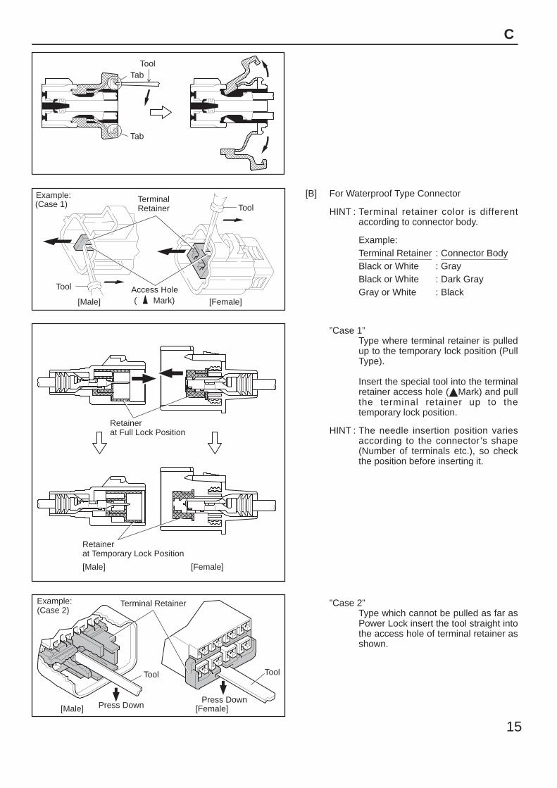
[B] For Waterproof Type Connector
HINT : Terminal retainer color is differentaccording to connector body.
Example:Terminal Retainer : Connector BodyBlack or White : GrayBlack or White : Dark GrayGray or White : Black
”Case 1”Type where terminal retainer is pulledup to the temporary lock position (PullType).
Insert the special tool into the terminalretainer access hole (Mark) and pullthe terminal retainer up to thetemporary lock position.
HINT : The needle insertion position variesaccording to the connector’s shape(Number of terminals etc.), so checkthe position before inserting it.
”Case 2”Type which cannot be pulled as far asPower Lock insert the tool straight intothe access hole of terminal retainer asshown.
Retainer atFull Lock Position
[Male] [Female]
Retainer atTemporary Lock Position
Locking Lug
Tool
16
C TROUBLESHOOTING
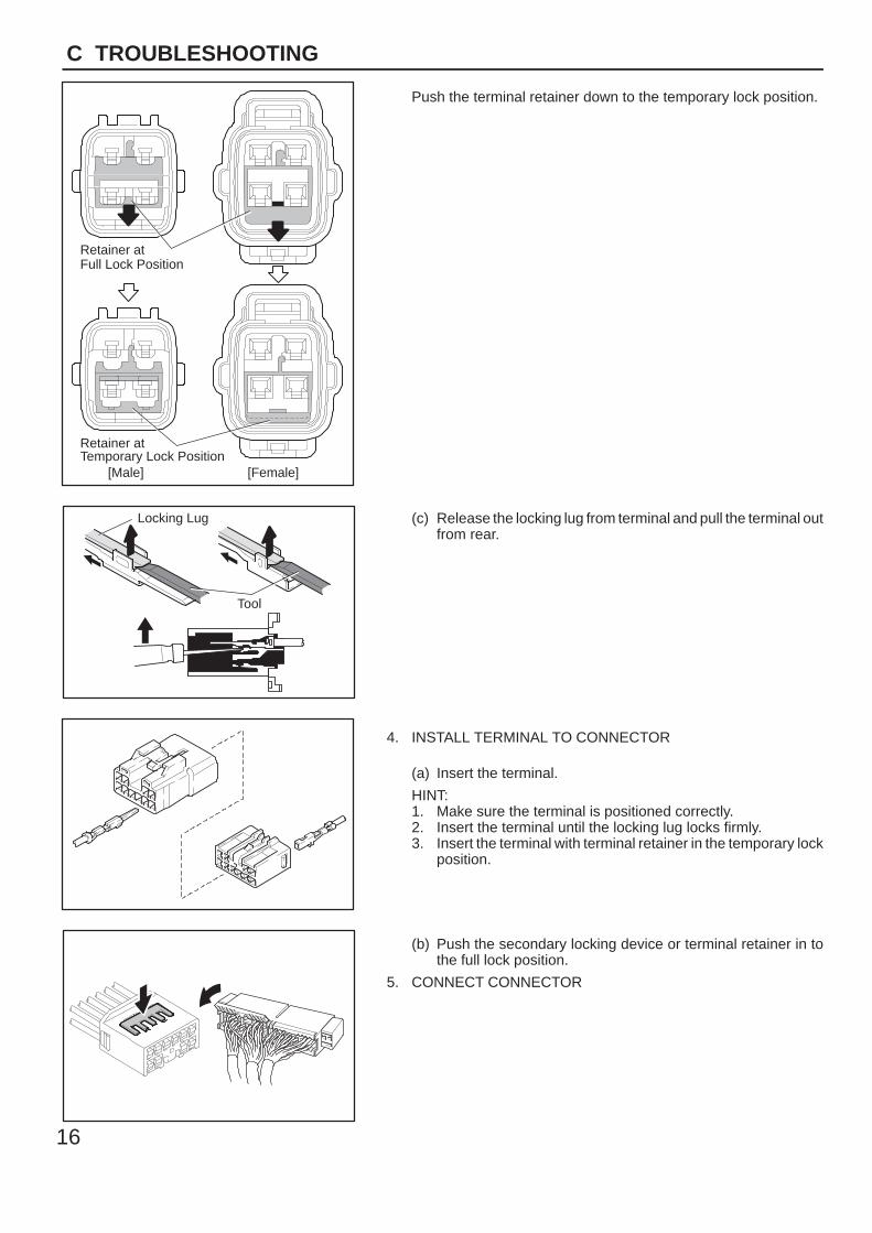
Push the terminal retainer down to the temporary lock position.
(c) Release the locking lug from terminal and pull the terminal outfrom rear.
4. INSTALL TERMINAL TO CONNECTOR
(a) Insert the terminal.
HINT:1. Make sure the terminal is positioned correctly.2. Insert the terminal until the locking lug locks firmly.3. Insert the terminal with terminal retainer in the temporary lock
position.
(b) Push the secondary locking device or terminal retainer in tothe full lock position.
5. CONNECT CONNECTOR
∗ The titles given inside the components are the names of the terminals (terminal codes) and are not treated as beingabbreviations.
17
ABBREVIATIONS D
ABBREVIATIONS
The following abbreviations are used in this manual.
2WD = Two Wheel Drive Vehicles
4WD = Four Wheel Drive Vehicles
A/C = Air Conditioner
A/T = Automatic Transmission
ABS = Anti–Lock Brake System
ADD = Automatic Disconnecting Differential
CAN = Controller Area Network
CD = Compact Disc
DLC3 = Data Link Connector 3
ECT = Electronic Control Transmission
ECU = Electronic Control Unit
EDU = Electronic Driving Unit
EGR = Exhaust Gas Recirculation
IC = Integrated Circuit
INT = Intermittent
J/B = Junction Block
LCD = Liquid Crystal Display
LH = Left–Hand
M/T = Manual Transmission
R/B = Relay Block
RH = Right–Hand
SRS = Supplemental Restraint System
SW = Switch
TEMP. = Temperature
VRV = Vacuum Regulating Valve
VSV = Vacuum Switching Valve
w/ = With
w/o = Without
18
E GLOSSARY OF TERMS AND SYMBOLS
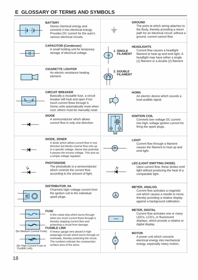
BATTERYStores chemical energy andconverts it into electrical energy.Provides DC current for the auto’svarious electrical circuits.
GROUNDThe point at which wiring attaches tothe Body, thereby providing a returnpath for an electrical circuit; without aground, current cannot flow.
CAPACITOR (Condenser)A small holding unit for temporarystorage of electrical voltage.
HEADLIGHTSCurrent flow causes a headlightfilament to heat up and emit light. Aheadlight may have either a single(1) filament or a double (2) filament
1. SINGLE FILAMENT
CIGARETTE LIGHTERAn electric resistance heatingelement.
2. DOUBLE FILAMENT
CIRCUIT BREAKERBasically a reusable fuse, a circuitbreaker will heat and open if toomuch current flows through it.Some units automatically reset whencool, others must be manually reset.
HORNAn electric device which sounds aloud audible signal.
DIODEA semiconductor which allowscurrent flow in only one direction.
IGNITION COILConverts low–voltage DC currentinto high–voltage ignition current forfiring the spark plugs.
DIODE, ZENERA diode which allows current flow in onedirection but blocks reverse flow only upto a specific voltage. Above that potential,it passes the excess voltage. This acts asa simple voltage regulator.
LIGHTCurrent flow through a filamentcauses the filament to heat up andemit light.
PHOTODIODEThe photodiode is a semiconductorwhich controls the current flowaccording to the amount of light.
LED (LIGHT EMITTING DIODE)Upon current flow, these diodes emitlight without producing the heat of acomparable light.
DISTRIBUTOR, IIAChannels high–voltage current fromthe ignition coil to the individualspark plugs.
METER, ANALOGCurrent flow activates a magneticcoil which causes a needle to move,thereby providing a relative displayagainst a background calibration.
FUSEA thin metal strip which burns throughwhen too much current flows through it,thereby stopping current flow andprotecting a circuit from damage.
FUSIBLE LINK
METER, DIGITALCurrent flow activates one or manyLED’s, LCD’s, or fluorescentdisplays, which provide a relative ordigital display.
FUEL
FUSIBLE LINKA heavy–gauge wire placed in highamperage circuits which burns through onoverloads, thereby protecting the circuit.The numbers indicate the crosssectionsurface area of the wires.
(for Medium Current Fuse)
(for High Current Fuse or Fusible Link)
MOTORA power unit which convertselectrical energy into mechanicalenergy, especially rotary motion.
M
19
E
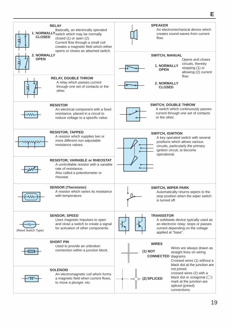
RELAYBasically, an electrically operatedswitch which may be normallyclosed (1) or open (2).Current flow through a small coilcreates a magnetic field which eitheropens or closes an attached switch.
1. NORMALLY CLOSED
2. NORMALLY OPEN
SWITCH, MANUALOpens and closescircuits, thereby
SPEAKERAn electromechanical device whichcreates sound waves from currentflow.
RELAY, DOUBLE THROWA relay which passes currentthrough one set of contacts or theother.
Opens and closescircuits, therebystopping (1) orallowing (2) currentflow.
1. NORMALLY OPEN
2. NORMALLY CLOSED
RESISTORAn electrical component with a fixedresistance, placed in a circuit toreduce voltage to a specific value.
SWITCH, DOUBLE THROWA switch which continuously passescurrent through one set of contactsor the other.
RESISTOR, TAPPEDA resistor which supplies two ormore different non adjustableresistance values.
SWITCH, IGNITIONA key operated switch with severalpositions which allows variouscircuits, particularly the primaryignition circuit, to becomeoperational.
RESISTOR, VARIABLE or RHEOSTATA controllable resistor with a variablerate of resistance.Also called a potentiometer orrheostat.
operational.
SENSOR (Thermistor)A resistor which varies its resistancewith temperature.
SWITCH, WIPER PARKAutomatically returns wipers to thestop position when the wiper switchis turned off.
(Reed Switch Type)
SENSOR, SPEEDUses magnetic impulses to openand close a switch to create a signalfor activation of other components.
TRANSISTORA solidstate device typically used asan electronic relay; stops or passescurrent depending on the voltageapplied at ”base”.
SHORT PINUsed to provide an unbrokenconnection within a junction block.
WIRESWires are always drawn asstraight lines on wiringdiagrams.Crossed wires (1) without ablack dot at the junction are
(1) NOT CONNECTED
SOLENOIDAn electromagnetic coil which formsa magnetic field when current flows,to move a plunger, etc.
black dot at the junction arenot joined;crossed wires (2) with ablack dot or octagonal ( )mark at the junction arespliced (joined)connections.
(2) SPLICED
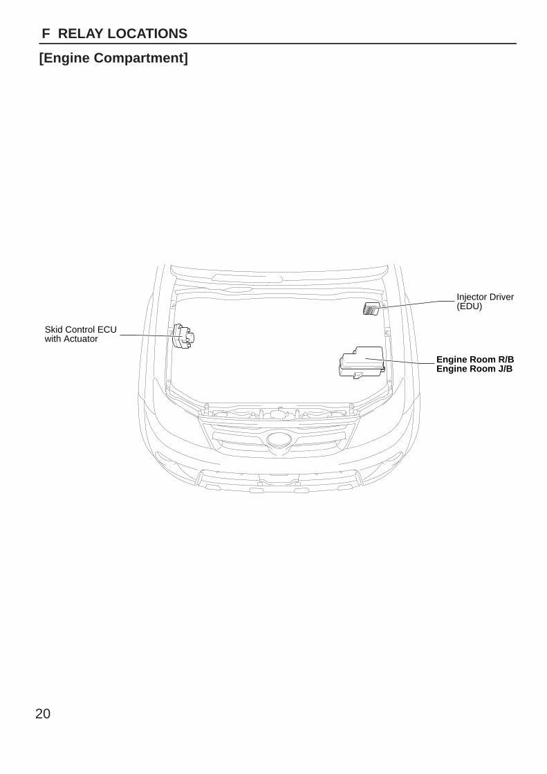
Engine Room R/BEngine Room J/B
Injector Driver(EDU)
Skid Control ECUwith Actuator
20
F RELAY LOCATIONS
[Engine Compartment]
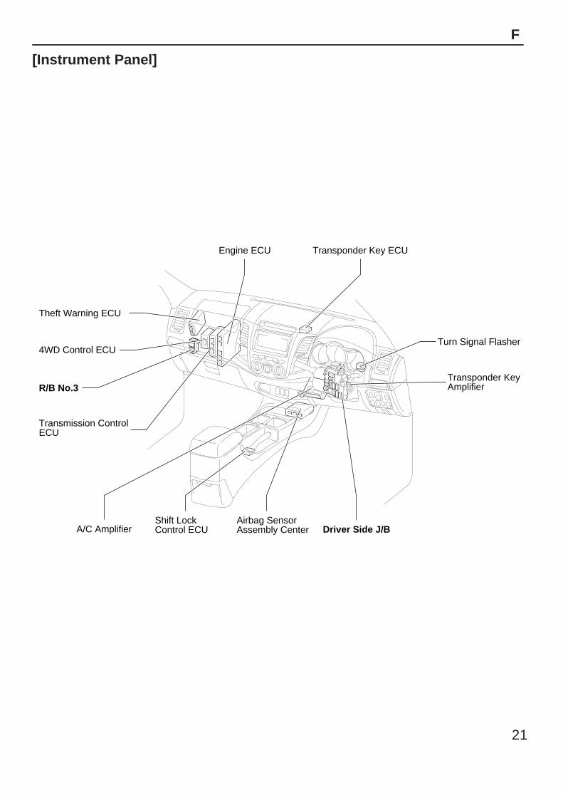
Airbag Sensor Assembly Center
Transponder KeyAmplifier
Turn Signal Flasher
Shift LockControl ECUA/C Amplifier
R/B No.3
Theft Warning ECU
4WD Control ECU
Transmission ControlECU
Driver Side J/B
Transponder Key ECUEngine ECU
21
F
[Instrument Panel]
*1
*2
*3
*4
*5
*6
*7
*81 215A
FOG
1 210AHORN
1 225AEFI
130ADCC
2
2 20AH-LP RH
1
2 20AH-LP LH
1
17.5AALT-S
2
17.5ADOME
2
17.5AECU-B
RAD
2
115ATURN-HAZ
2
115A 2
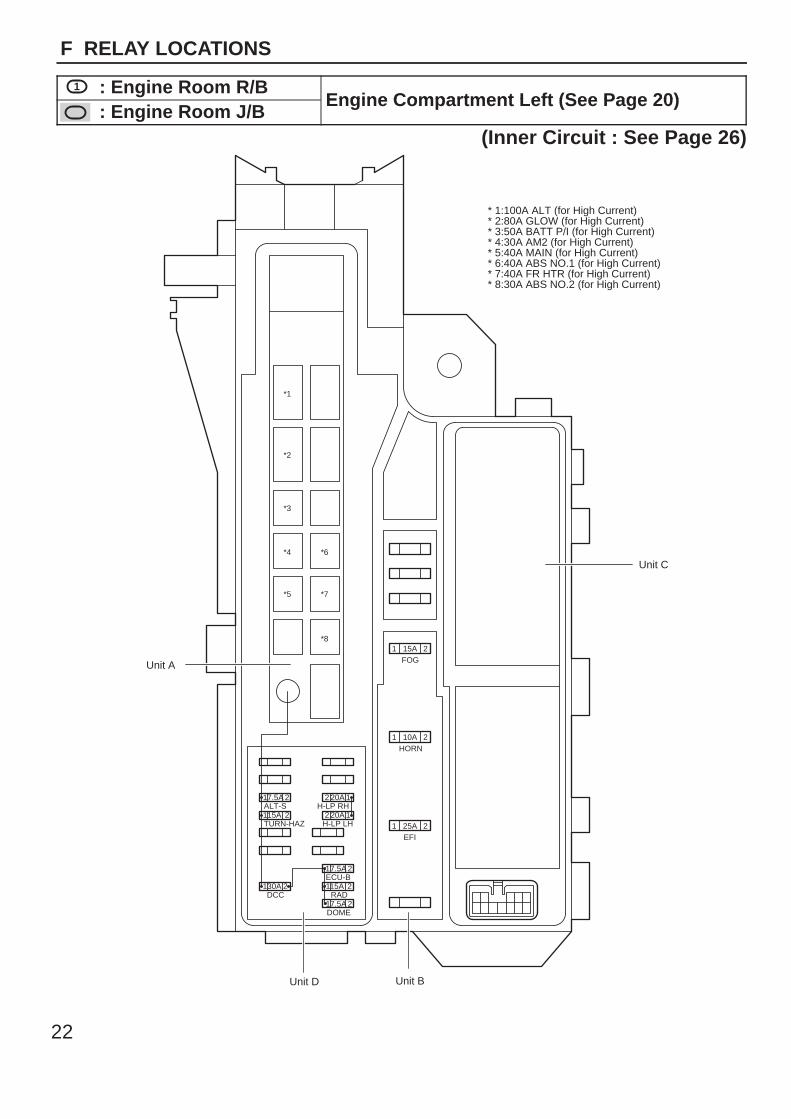
Unit D
* 1:100A ALT (for High Current)* 2:80A GLOW (for High Current)* 3:50A BATT P/I (for High Current)* 4:30A AM2 (for High Current)* 5:40A MAIN (for High Current)* 6:40A ABS NO.1 (for High Current)* 7:40A FR HTR (for High Current)* 8:30A ABS NO.2 (for High Current)
Unit C
Unit B
Unit A
22
F RELAY LOCATIONS
1 : Engine Room R/BEngine Compartment Left (See Page 20)
: Engine Room J/BEngine Compartment Left (See Page 20)
(Inner Circuit : See Page 26)
3 4
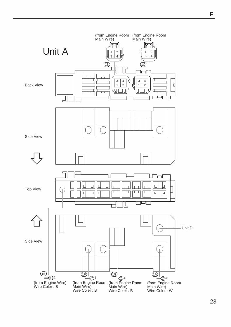
Unit D
1 24321
4321
4321
1 1 11
Back View
Side View
Side View
Top View
(from Engine Room Main Wire)
(from Engine Room Main Wire)
(from Engine Wire)Wire Coler : B
(from Engine Room Main Wire)Wire Coler : B
(from Engine Room Main Wire)Wire Coler : B
(from Engine Room Main Wire)Wire Coler : W
1B
1E 1F 1G 1A
1C
Unit A
23
F
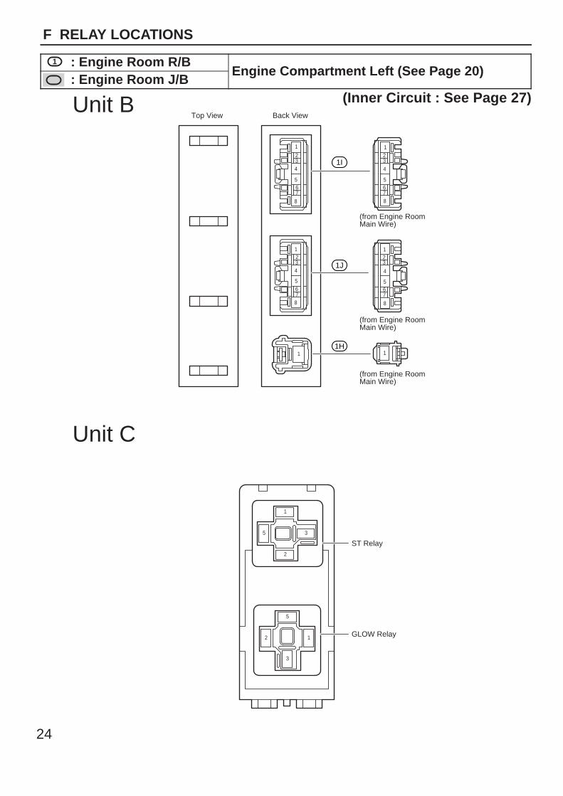
23
4
567
8
1
8
765
432
1
ST Relay
GLOW Relay
Back View
(from Engine Room Main Wire)
(from Engine Room Main Wire)
(from Engine Room Main Wire)
1
8765
4321
123
4
5678
1
12
3
5
1
2
35
1I
1J
1H
Unit B
Unit C
Top View
24
F RELAY LOCATIONS
1 : Engine Room R/BEngine Compartment Left (See Page 20)
: Engine Room J/BEngine Compartment Left (See Page 20)
(Inner Circuit : See Page 27)

25
Memo
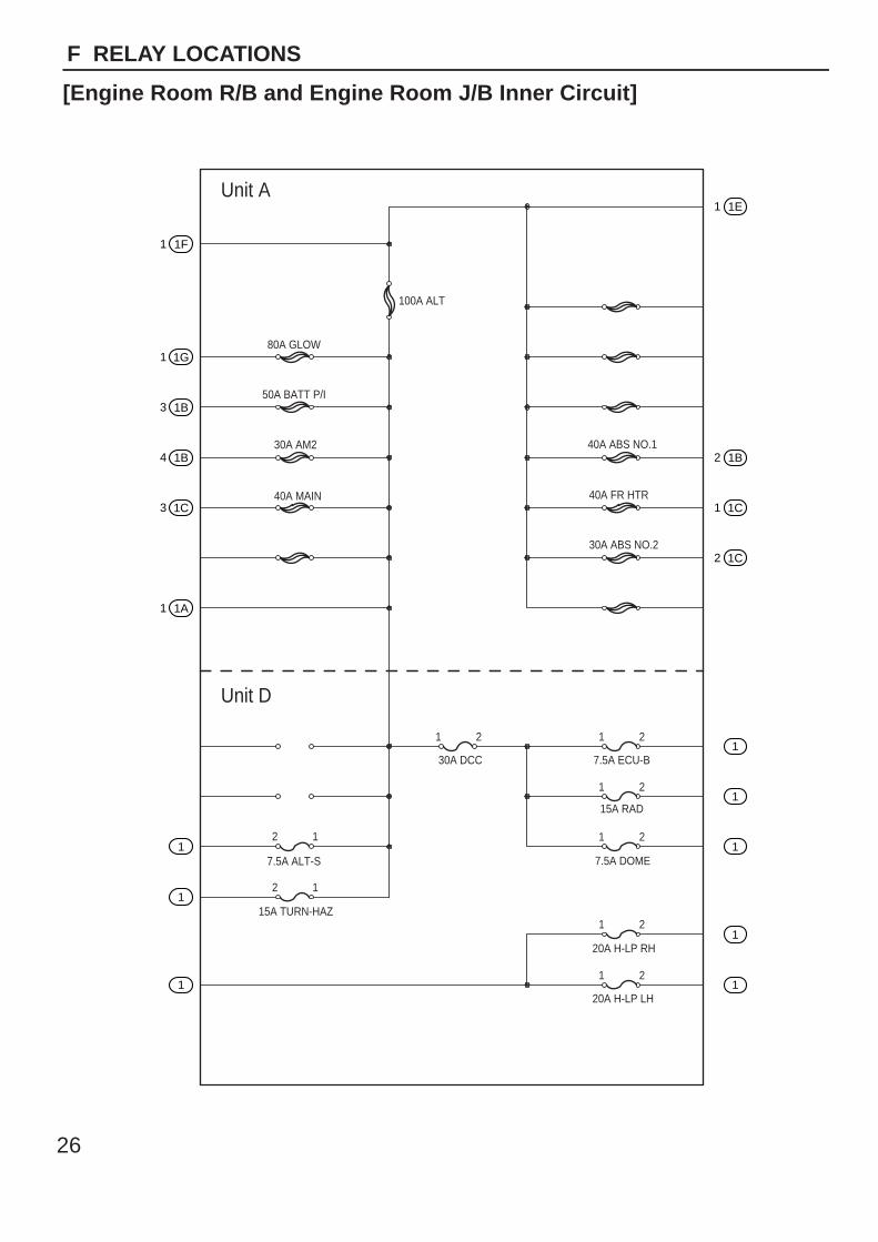
1 1F
1 1E
2 1B
1 1C
2 1C
1
1
1
1
1
1 1G
3 1B
4 1B
3 1C
1 1A
1
1
1
Unit A
Unit D
80A GLOW
100A ALT
40A ABS NO.1
40A FR HTR
30A ABS NO.2
30A AM2
40A MAIN
30A DCC 7.5A ECU-B
15A RAD
7.5A DOME
20A H-LP RH
20A H-LP LH
7.5A ALT-S
15A TURN-HAZ
50A BATT P/I
21 21
21
21
21
21
12
12
26
F RELAY LOCATIONS
[Engine Room R/B and Engine Room J/B Inner Circuit]
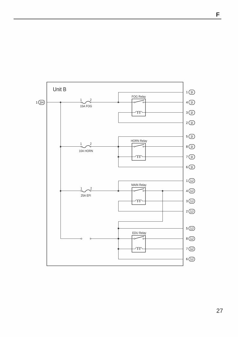
1 1H
1 1I
4 1I
3 1I
2 1I
5 1I
8 1I
7 1I
6 1I
1 1J
4 1J
3 1J
2 1J
5 1J
8 1J
7 1J
6 1J
Unit B
1 2
1 2
1 2
15A FOG
FOG Relay
HORN Relay
MAIN Relay
EDU Relay
10A HORN
25A EFI
27
F
2 1
34
1
1
2
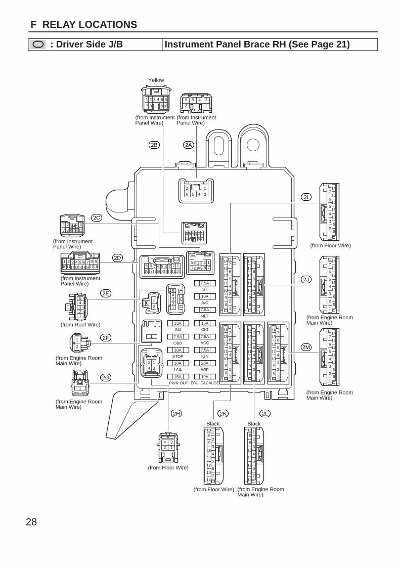
5
7.5A
ST
7.5A
MET
7.5A
ACC
7.5A
IGN
20A
WIP
10A
ECU-IG&GAUGE
15A
CIG
15A
INJ
7.5A
OBD
10A
STOP
10A
TAIL
15A
PWR OUT
10A
A/C
4321
9 8 7 6 5 4 3 2 1101112131415161718
9101112 8 76 5 4 3 2 1
910 8 76 5 4 3 2 1
2 1
6 5 4 3
12
34561 2 3 4 5 6
107 8 9
1 2 3 4 5 67 8
(from Instrument Panel Wire)
(from Instrument Panel Wire)
(from Instrument Panel Wire)
(from Instrument Panel Wire)
(from Roof Wire)
(from Engine Room Main Wire)
(from Engine Room Main Wire)
(from Engine Room Main Wire)
(from Engine Room Main Wire)
(from Engine Room Main Wire)
(from Floor Wire)
(from Floor Wire)
(from Floor Wire)
Yellow
Black Black
9101112
1 2 3 4 5 6 7 8 9101112131415161718
1234
1
1
2
12345
1
2
3
4
5
6
7
8
9
10
11
12
13
14
1
2
3
4
5
6
7
8
9
10
11
12
13
14
1
2
3
4
5
6
7
10
11
12
13
14
8
9
1
2
3
4
5
6
7
10
11
12
13
14
8
9
1
2
3
4
5
6
7
10
11
12
13
14
8
9
1
2
3
4
5
6
7
10
11
12
13
14
8
9
1
2
3
4
5
6
7
10
11
12
13
14
8
9
1
2
3
4
5
6
7
10
11
12
13
14
8
9
1
2
3
4
5
6
7
10
11
12
13
14
8
9
1
2
3
4
5
6
7
10
11
12
13
14
8
9
2B
2C
2D
2E
2F
2G
2H 2K 2L
2M
2J
2I
2A
28
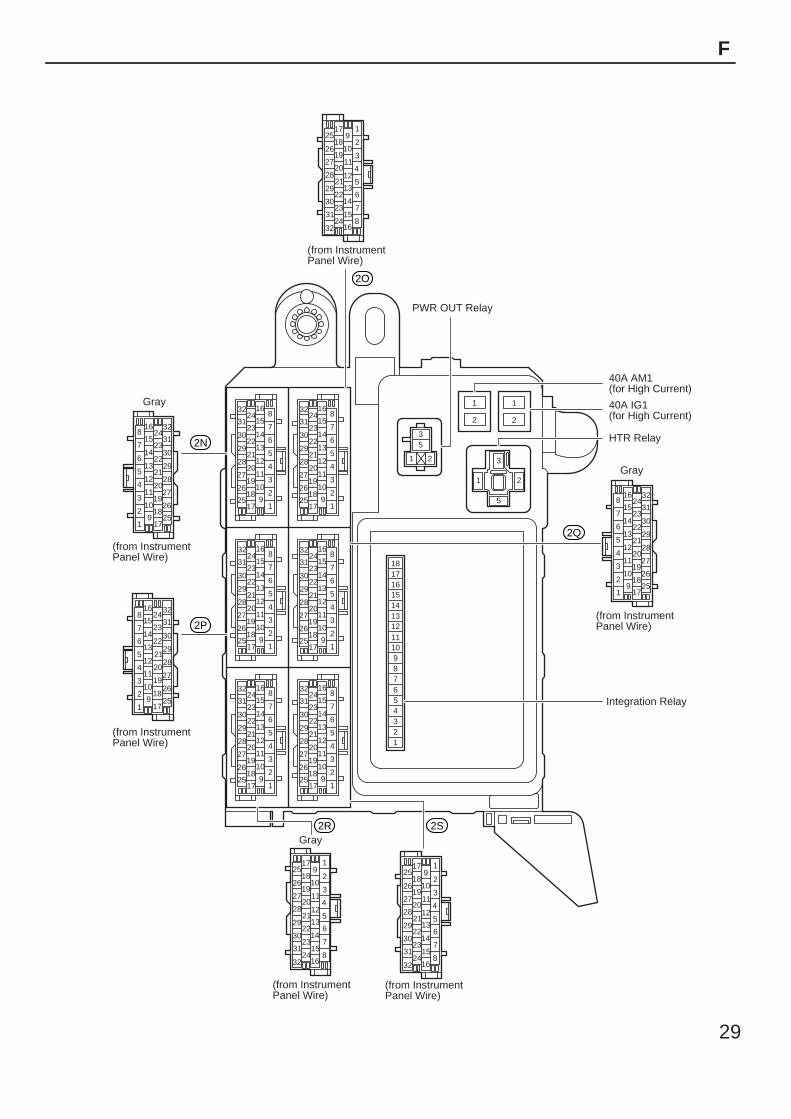
F RELAY LOCATIONS
: Driver Side J/B Instrument Panel Brace RH (See Page 21)
1 2
3
5
35
1 2
1
2
1
2
9101112131415161718
87654321
1
2
3
4
5
6
7
8
9
10
11
12
13
14
15
16
17
18
19
20
21
22
23
24
25
26
27
28
29
30
31
32
1
2
3
4
5
6
7
8
9
10
11
12
13
14
15
16
17
18
19
20
21
22
23
24
25
26
27
28
29
30
31
32
1
2
3
4
5
6
7
8
9
10
11
12
13
14
15
16
17
18
19
20
21
22
23
24
25
26
27
28
29
30
31
32
1
2
3
4
5
6
7
8
9
10
11
12
13
14
15
16
17
18
19
20
21
22
23
24
25
26
27
28
29
30
31
32
1
2
3
4
5
6
7
8
9
10
11
12
13
14
15
16
17
18
19
20
21
22
23
24
25
26
27
28
29
30
31
32
1
2
3
4
5
6
7
8
9
10
11
12
13
14
15
16
17
18
19
20
21
22
23
24
25
26
27
28
29
30
31
32
1
2
3
4
5
6
7
8
9
10
11
12
13
14
15
16
17
18
19
20
21
22
23
24
25
26
27
28
29
30
31
32
1
2
3
4
5
6
7
8
Gray
Gray
(from Instrument Panel Wire)
Gray
(from Instrument Panel Wire)
(from Instrument Panel Wire)
(from Instrument Panel Wire)
(from Instrument Panel Wire)
Integration Relay
HTR Relay
40A IG1(for High Current)
40A AM1(for High Current)
PWR OUT Relay
(from Instrument Panel Wire)
9
10
11
12
13
14
15
16
17
18
19
20
21
22
23
24
25
26
27
28
29
30
31
32
1
2
3
4
5
6
7
8
9
10
11
12
13
14
15
16
17
18
19
20
21
22
23
24
25
26
27
28
29
30
31
32
1
2
3
4
5
6
7
8
9
10
11
12
13
14
15
16
17
18
19
20
21
22
23
24
25
26
27
28
29
30
31
32
1
2
3
4
5
6
7
8
9
10
11
12
13
14
15
16
17
18
19
20
21
22
23
24
25
26
27
28
29
30
31
32
1
2
3
4
5
6
7
8
9
10
11
12
13
14
15
16
17
18
19
20
21
22
23
24
25
26
27
28
29
30
31
32
2O
2N
2P
2R 2S
2Q
29
F
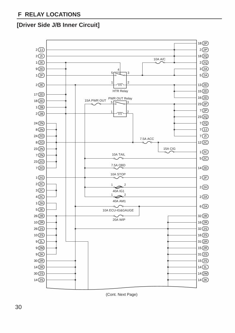
2 2J
2 2I
1 2E
9 2D
1 2F
2 2E
17 2D
18 2D
1 2B
2 2B
24 2N
8 2N
24 2O
8 2O
23 2N
7 2N
23 2O
7 2O
1 2G
2 2C
3 2C
4 2C
1 2H
5 2E
26 2R
10 2R
26 2S
10 2S
9 2L
9 2M
9 2K
30 2R
14 2R
30 2S
14 2S
2 2P
18 2P
18 2Q
2 2Q
3 2A
5 2A
13 2D
15 2D
16 2D
23 2P
7 2P
23 2Q
7 2Q
7 2J
7 2I
12 2C
1 2C
5 2C
14 2D
2 2F
2 2H
2 2A
6 2A
32 2R
16 2R
32 2S
16 2S
31 2R
15 2R
31 2S
15 2S
14 2L
14 2M
14 2K
54
1
HTR Relay
PWR OUT Relay15A PWR OUT
7.5A ACC
15A CIG
10A TAIL
7.5A OBD
10A STOP
40A IG1
40A AM1
20A WIP
10A ECU-IG&GAUGE
10A A/C
3
2
5
1
3
2
21
21
(Cont. Next Page)
30
F RELAY LOCATIONS
[Driver Side J/B Inner Circuit]
13 2L
13 2M
13 2K
4 2L
4 2M
4 2K
8 2L
8 2M
8 2K
7 2C
6 2C
3 2B
21 2N
5 2N
21 2O
5 2O
8 2C
9 2C
10 2C
11 2C
24 2R
8 2R
24 2S
8 2S
25 2P
9 2P
25 2Q
9 2Q
8 2J
8 2I
4 2E
32 2N
16 2N
32 2O
16 2O
20 2R
4 2R
20 2S
4 2S
25 2R
9 2R
25 2S
9 2S
19 2N
3 2N
19 2O
3 2O
22 2R
6 2R
22 2S
6 2S
6 2L
6 2M
6 2K
8 2B
1 2D
10 2D
11 2D
12 2D
4 2B
21 2P
5 2P
21 2Q
5 2Q
5 2J
5 2I
7 2B
22 2P
6 2P
22 2Q
6 2Q
6 2J
6 2I
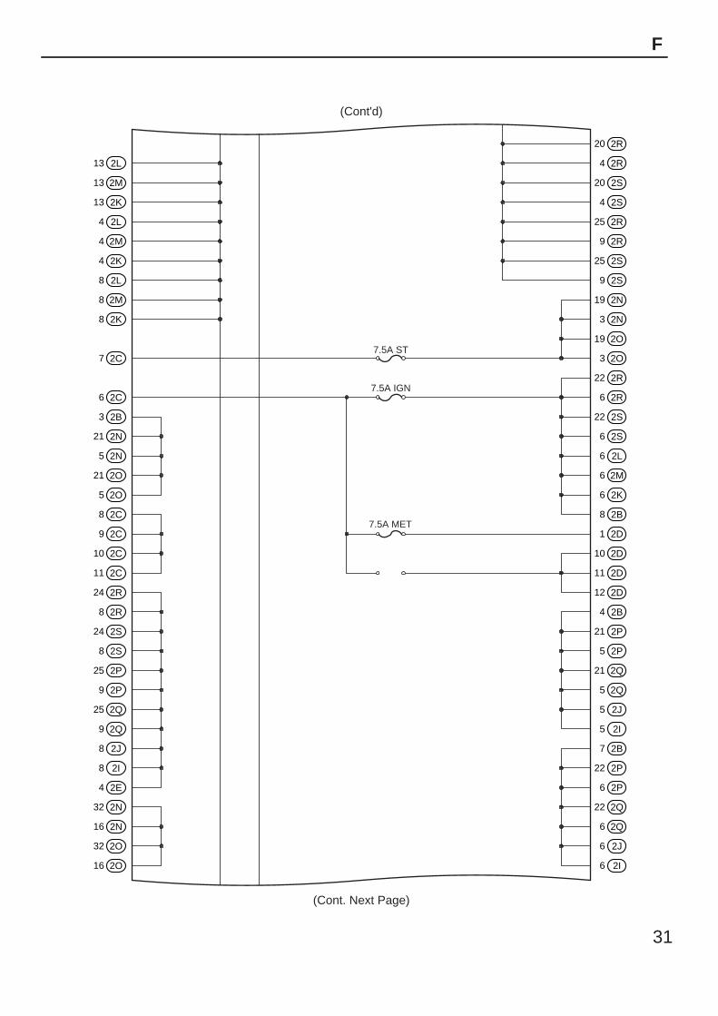
7.5A ST
7.5A IGN
7.5A MET
(Cont'd)
(Cont. Next Page)
31
F
4 2H
7 2D
6 2D
5 2D
4 2D
3 2D
2 2D
3 2E
31 2N
15 2N
31 2O
15 2O
30 2N
14 2N
30 2O
14 2O
1 2A
4 2A
28 2N
12 2N
28 2O
12 2O
27 2N
11 2N
27 2O
11 2O
22 2N
6 2N
22 2O
6 2O
29 2N
13 2N
29 2O
13 2O
26 2N
10 2N
26 2O
10 2O
25 2N
9 2N
25 2O
9 2O
27 2R
11 2R
27 2S
11 2S
10 2L
10 2M
10 2K
28 2R
12 2R
28 2S
12 2S
11 2L
11 2M
11 2K
29 2R
13 2R
29 2S
13 2S
12 2L
12 2M
12 2K
20 2N
4 2N
20 2O
4 2O
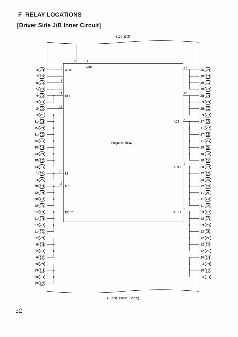
16DCTY
ILE
L1
UL1
ALTBGND
ACT-
Integration Relay
ACT+
BECU
15
14
13
12
11
10
9
8
5
6 1
17
18
2
3
4
(Cont'd)
(Cont. Next Page)
32
F RELAY LOCATIONS
[Driver Side J/B Inner Circuit]
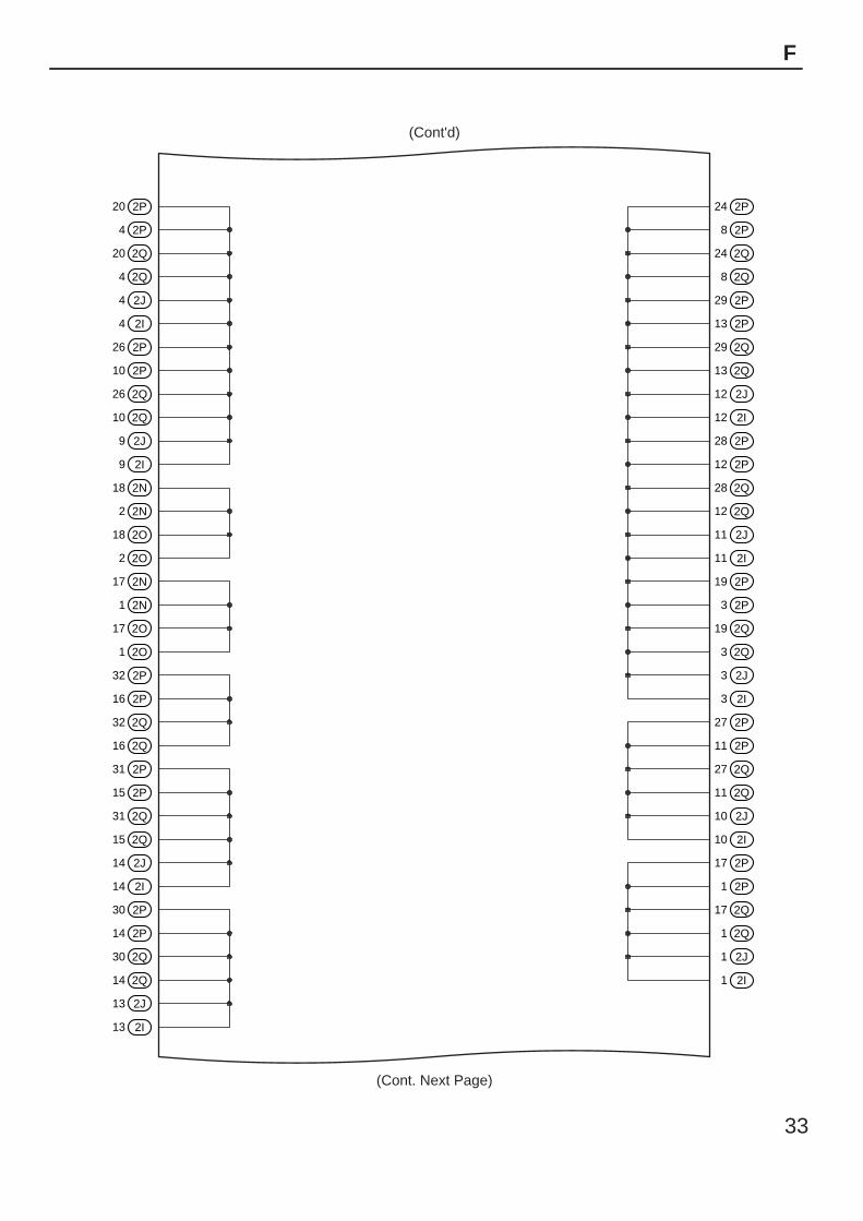
20 2P
4 2P
20 2Q
4 2Q
4 2J
4 2I
26 2P
10 2P
26 2Q
10 2Q
9 2J
9 2I
18 2N
2 2N
18 2O
2 2O
17 2N
1 2N
17 2O
1 2O
32 2P
16 2P
32 2Q
16 2Q
31 2P
15 2P
31 2Q
15 2Q
14 2J
14 2I
30 2P
14 2P
30 2Q
14 2Q
13 2J
13 2I
24 2P
8 2P
24 2Q
8 2Q
29 2P
13 2P
29 2Q
13 2Q
12 2J
12 2I
28 2P
12 2P
28 2Q
12 2Q
11 2J
11 2I
19 2P
3 2P
19 2Q
3 2Q
3 2J
3 2I
27 2P
11 2P
27 2Q
11 2Q
10 2J
10 2I
17 2P
1 2P
17 2Q
1 2Q
1 2J
1 2I
(Cont'd)
(Cont. Next Page)
33
F
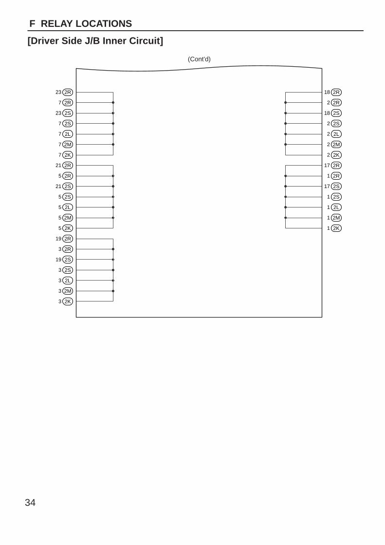
23 2R
7 2R
23 2S
7 2S
7 2L
7 2M
7 2K
21 2R
5 2R
21 2S
5 2S
5 2L
5 2M
5 2K
19 2R
18 2R
2 2R
18 2S
2 2S
2 2L
2 2M
2 2K
17 2R
1 2R
17 2S
1 2S
1 2L
1 2M
1 2K
3 2R
19 2S
3 2S
3 2L
3 2M
3 2K
(Cont'd)
34
F RELAY LOCATIONS
[Driver Side J/B Inner Circuit]
5 3
2
1
35
1
2
2 1
1
2
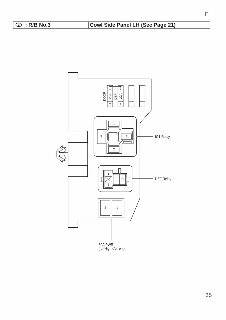
25A
20A
DO
OR
DE
F
2
IG1 Relay
DEF Relay
30A PWR(for High Current)
1
35
F
3 : R/B No.3 Cowl Side Panel LH (See Page 21)
36
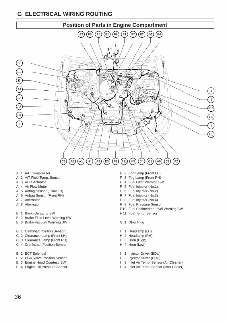
G ELECTRICAL WIRING ROUTING
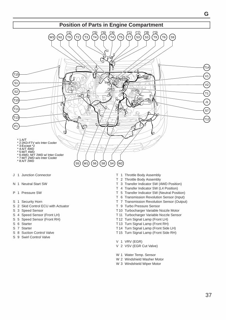
Position of Parts in Engine Compartment
A4
I3
B2
B3
A8
A7
H2
F3
I1
I2
F10
F4
I4
H1
F7A2 F8B1 E1F6F5 E2 G1 E4
E3H4 A3A1A6C3 F11F9 H3 C4 C1 A5 C2 F2
A 1 A/C CompressorA 2 A/T Fluid Temp. SensorA 3 ADD ActuatorA 4 Air Flow MeterA 5 Airbag Sensor (Front LH)A 6 Airbag Sensor (Front RH)A 7 AlternatorA 8 Alternator
B 1 Back–Up Lamp SWB 2 Brake Fluid Level Warning SWB 3 Brake Vacuum Warning SW
C 1 Camshaft Position SensorC 2 Clearance Lamp (Front LH)C 3 Clearance Lamp (Front RH)C 4 Crankshaft Position Sensor
E 1 ECT SolenoidE 2 EGR Valve Position SensorE 3 Engine Hood Courtesy SWE 4 Engine Oil Pressure Sensor
F 2 Fog Lamp (Front LH)F 3 Fog Lamp (Front RH)F 4 Fuel Filter Warning SWF 5 Fuel Injector (No.1)F 6 Fuel Injector (No.2)F 7 Fuel Injector (No.3)F 8 Fuel Injector (No.4)F 9 Fuel Pressure SensorF 10 Fuel Sedimenter Level Warning SWF 11 Fuel Temp. Sensor
G 1 Glow Plug
H 1 Headlamp (LH)H 2 Headlamp (RH)H 3 Horn (High)H 4 Horn (Low)
I 1 Injector Driver (EDU)I 2 Injector Driver (EDU)I 3 Inlet Air Temp. Sensor (Air Cleaner)I 4 Inlet Air Temp. Sensor (Inter Cooler)
37
G
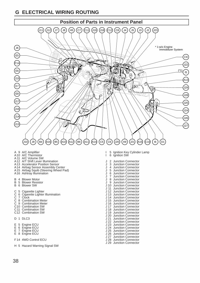
Position of Parts in Engine Compartment
S1
S2
T15
T10
T11
T13
P1
V2
T1
J1
V1
T14
S7
T12
T2N1 T9
(*2)
W3 S3
(*6)
S3
(*8)
S3
(*7)
T4
(*5)
T3 T4
(*4)
T5 T9
(*3)
* 2:2KD-FTV w/o Inter Cooler* 1:A/T
* 3:Except *2* 4:A/T 4WD* 5:M/T 4WD* 6:4WD, M/T 2WD w/ Inter Cooler* 7:M/T 2WD w/o Inter Cooler* 8:A/T 2WD
S9T6T7
(*1)
S8S6W1S5 W2S4
J 1 Junction Connector
N 1 Neutral Start SW
P 1 Pressure SW
S 1 Security HornS 2 Skid Control ECU with ActuatorS 3 Speed SensorS 4 Speed Sensor (Front LH)S 5 Speed Sensor (Front RH)S 6 StarterS 7 StarterS 8 Suction Control ValveS 9 Swirl Control Valve
T 1 Throttle Body AssemblyT 2 Throttle Body AssemblyT 3 Transfer Indicator SW (4WD Position)T 4 Transfer Indicator SW (L4 Position)T 5 Transfer Indicator SW (Neutral Position)T 6 Transmission Revolution Sensor (Input)T 7 Transmission Revolution Sensor (Output)T 9 Turbo Pressure SensorT 10 Turbocharger Variable Nozzle MotorT 11 Turbocharger Variable Nozzle SensorT 12 Turn Signal Lamp (Front LH)T 13 Turn Signal Lamp (Front RH)T 14 Turn Signal Lamp (Front Side LH)T 15 Turn Signal Lamp (Front Side RH)
V 1 VRV (EGR)V 2 VSV (EGR Cut Valve)
W 1 Water Temp. SensorW 2 Windshield Washer MotorW 3 Windshield Wiper Motor
38
G ELECTRICAL WIRING ROUTING
Position of Parts in Instrument Panel
E7
E6
E5
F14
J6
J15
E8
J17
J16
J14
J13
C9
A13
J29
J22
I5(*1)
* 1:w/o EngineImmobilizer System
J28
J25
J24
J26
J27
J8J7J12J11 C7H5 J5C8 J4C11 C12J19 J18 J3 J2 J23
C5A14A12 A11A10 B6B5A16B4J9J10 A9C6 A15 C10 I6 D1J20 J21
A 9 A/C AmplifierA10 A/C ThermistorA 11 A/C Volume SWA12 A/T Shift Lever IlluminationA13 Accelerator Position SensorA14 Airbag Sensor Assembly CenterA15 Airbag Squib (Steering Wheel Pad)A16 Ashtray Illumination
B 4 Blower MotorB 5 Blower ResistorB 6 Blower SW
C 5 Cigarette LighterC 6 Cigarette Lighter IlluminationC 7 ClockC 8 Combination MeterC 9 Combination MeterC10 Combination SWC11 Combination SWC12 Combination SW
D 1 DLC3
E 5 Engine ECUE 6 Engine ECUE 7 Engine ECUE 8 Engine ECU
F 14 4WD Control ECU
H 5 Hazard Warning Signal SW
I 5 Ignition Key Cylinder LampI 6 Ignition SW
J 2 Junction ConnectorJ 3 Junction ConnectorJ 4 Junction ConnectorJ 5 Junction ConnectorJ 6 Junction ConnectorJ 7 Junction ConnectorJ 8 Junction ConnectorJ 9 Junction ConnectorJ 10 Junction ConnectorJ 11 Junction ConnectorJ 12 Junction ConnectorJ 13 Junction ConnectorJ 14 Junction ConnectorJ 15 Junction ConnectorJ 16 Junction ConnectorJ 17 Junction ConnectorJ 18 Junction ConnectorJ 19 Junction ConnectorJ 20 Junction ConnectorJ 21 Junction ConnectorJ 22 Junction ConnectorJ 23 Junction ConnectorJ 24 Junction ConnectorJ 25 Junction ConnectorJ 26 Junction ConnectorJ 27 Junction ConnectorJ 28 Junction ConnectorJ 29 Junction Connector
39
G
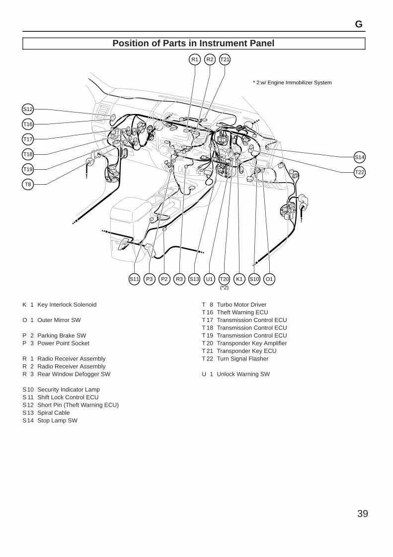
Position of Parts in Instrument Panel
T17
T16
S12
T18
T19
T8
S14
T22
R1 R2 T21
P2S11 R3P3 S13 U1 T20
(*2)
* 2:w/ Engine Immobilizer System
K1 S10 O1
K 1 Key Interlock Solenoid
O 1 Outer Mirror SW
P 2 Parking Brake SWP 3 Power Point Socket
R 1 Radio Receiver AssemblyR 2 Radio Receiver AssemblyR 3 Rear Window Defogger SW
S10 Security Indicator LampS 11 Shift Lock Control ECUS12 Short Pin (Theft Warning ECU)S13 Spiral CableS14 Stop Lamp SW
T 8 Turbo Motor DriverT 16 Theft Warning ECUT 17 Transmission Control ECUT 18 Transmission Control ECUT 19 Transmission Control ECUT 20 Transponder Key AmplifierT 21 Transponder Key ECUT 22 Turn Signal Flasher
U 1 Unlock Warning SW
40
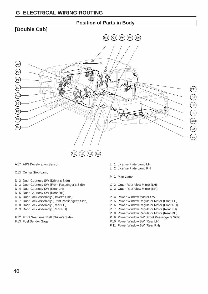
G ELECTRICAL WIRING ROUTING
Position of Parts in Body[Double Cab]
P5
P9
O2
D7
P10
D3
P7
D8
D4
P11
D9
P8
D5
C13
L2
L1
M1 O3 P6 P4 D6
D2F13A17F12
A17 ABS Deceleration Sensor
C13 Center Stop Lamp
D 2 Door Courtesy SW (Driver’s Side)D 3 Door Courtesy SW (Front Passenger’s Side)D 4 Door Courtesy SW (Rear LH)D 5 Door Courtesy SW (Rear RH)D 6 Door Lock Assembly (Driver’s Side)D 7 Door Lock Assembly (Front Passenger’s Side)D 8 Door Lock Assembly (Rear LH)D 9 Door Lock Assembly (Rear RH)
F 12 Front Seat Inner Belt (Driver’s Side)F 13 Fuel Sender Gage
L 1 License Plate Lamp LHL 2 License Plate Lamp RH
M 1 Map Lamp
O 2 Outer Rear View Mirror (LH)O 3 Outer Rear View Mirror (RH)
P 4 Power Window Master SWP 5 Power Window Regulator Motor (Front LH)P 6 Power Window Regulator Motor (Front RH)P 7 Power Window Regulator Motor (Rear LH)P 8 Power Window Regulator Motor (Rear RH)P 9 Power Window SW (Front Passenger’s Side)P10 Power Window SW (Rear LH)P 11 Power Window SW (Rear RH)
41
G
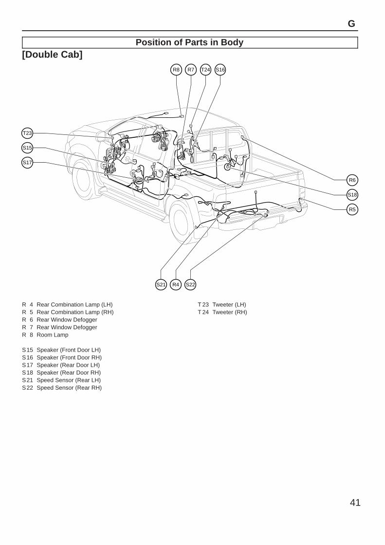
Position of Parts in Body[Double Cab]
S15
T23
S17
R6
S18
R5
R8 R7 T24 S16
R4S21 S22
R 4 Rear Combination Lamp (LH)R 5 Rear Combination Lamp (RH)R 6 Rear Window DefoggerR 7 Rear Window DefoggerR 8 Room Lamp
S15 Speaker (Front Door LH)S16 Speaker (Front Door RH)S17 Speaker (Rear Door LH)S18 Speaker (Rear Door RH)S21 Speed Sensor (Rear LH)S22 Speed Sensor (Rear RH)
T 23 Tweeter (LH)T 24 Tweeter (RH)
42
G ELECTRICAL WIRING ROUTING
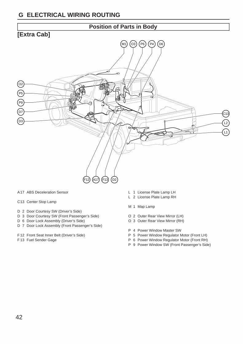
Position of Parts in Body[Extra Cab]
P5
O2
P9
D7
D3
C13
L2
L1
M1 O3 P6 P4 D6
D2F13A17F12
A17 ABS Deceleration Sensor
C13 Center Stop Lamp
D 2 Door Courtesy SW (Driver’s Side)D 3 Door Courtesy SW (Front Passenger’s Side)D 6 Door Lock Assembly (Driver’s Side)D 7 Door Lock Assembly (Front Passenger’s Side)
F 12 Front Seat Inner Belt (Driver’s Side)F 13 Fuel Sender Gage
L 1 License Plate Lamp LHL 2 License Plate Lamp RH
M 1 Map Lamp
O 2 Outer Rear View Mirror (LH)O 3 Outer Rear View Mirror (RH)
P 4 Power Window Master SWP 5 Power Window Regulator Motor (Front LH)P 6 Power Window Regulator Motor (Front RH)P 9 Power Window SW (Front Passenger’s Side)
43
G
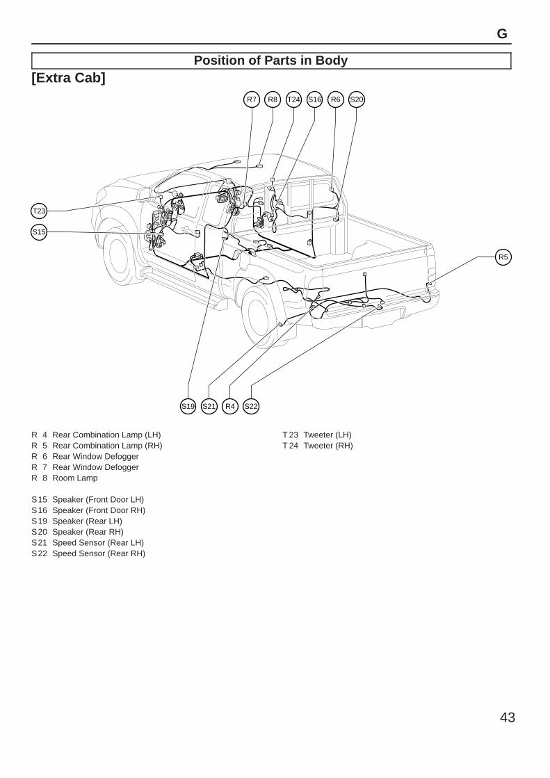
Position of Parts in Body[Extra Cab]
S15
T23
R5
R7 R8 T24 S16 R6 S20
R4S21S19 S22
R 4 Rear Combination Lamp (LH)R 5 Rear Combination Lamp (RH)R 6 Rear Window DefoggerR 7 Rear Window DefoggerR 8 Room Lamp
S15 Speaker (Front Door LH)S16 Speaker (Front Door RH)S19 Speaker (Rear LH)S20 Speaker (Rear RH)S21 Speed Sensor (Rear LH)S22 Speed Sensor (Rear RH)
T 23 Tweeter (LH)T 24 Tweeter (RH)
44
G ELECTRICAL WIRING ROUTING
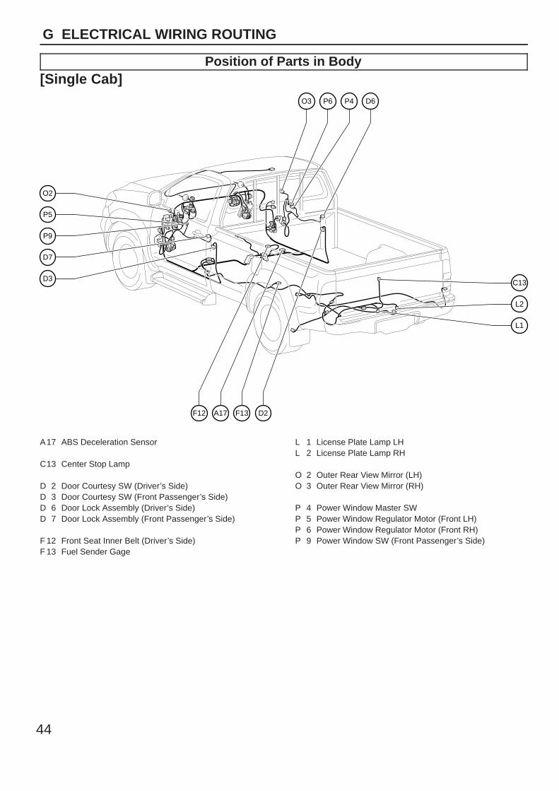
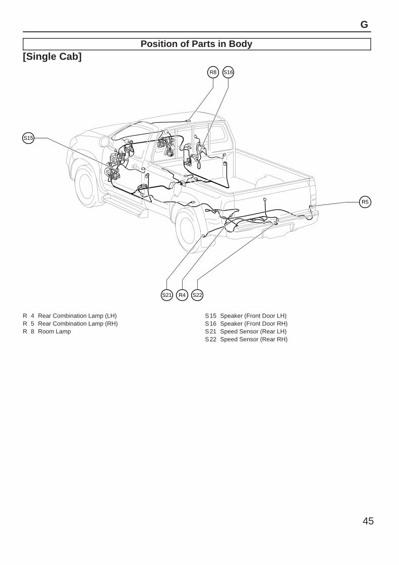
Position of Parts in Body[Single Cab]
P5
O2
P9
D7
D3 C13
L2
L1
O3 P6 P4 D6
D2F13A17F12
A17 ABS Deceleration Sensor
C13 Center Stop Lamp
D 2 Door Courtesy SW (Driver’s Side)D 3 Door Courtesy SW (Front Passenger’s Side)D 6 Door Lock Assembly (Driver’s Side)D 7 Door Lock Assembly (Front Passenger’s Side)
F 12 Front Seat Inner Belt (Driver’s Side)F 13 Fuel Sender Gage
L 1 License Plate Lamp LHL 2 License Plate Lamp RH
O 2 Outer Rear View Mirror (LH)O 3 Outer Rear View Mirror (RH)
P 4 Power Window Master SWP 5 Power Window Regulator Motor (Front LH)P 6 Power Window Regulator Motor (Front RH)P 9 Power Window SW (Front Passenger’s Side)
45
G
Position of Parts in Body[Single Cab]
S15
R5
R8 S16
R4S21 S22
R 4 Rear Combination Lamp (LH)R 5 Rear Combination Lamp (RH)R 8 Room Lamp
S15 Speaker (Front Door LH)S16 Speaker (Front Door RH)S21 Speed Sensor (Rear LH)S22 Speed Sensor (Rear RH)
46
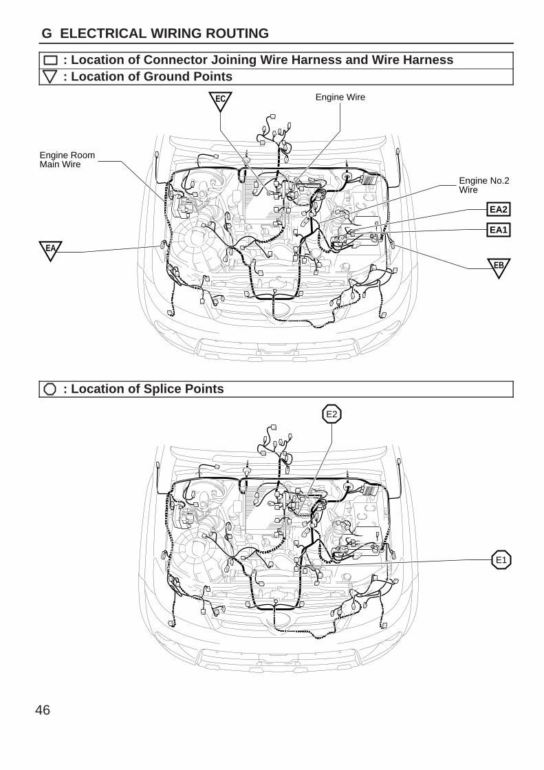
G ELECTRICAL WIRING ROUTING
: Location of Connector Joining Wire Harness and Wire Harness: Location of Ground Points
Engine Wire
Engine No.2 Wire
Engine RoomMain Wire
EC
EA2
EA1
EB
EA
: Location of Splice Points
E1
E2
47
G
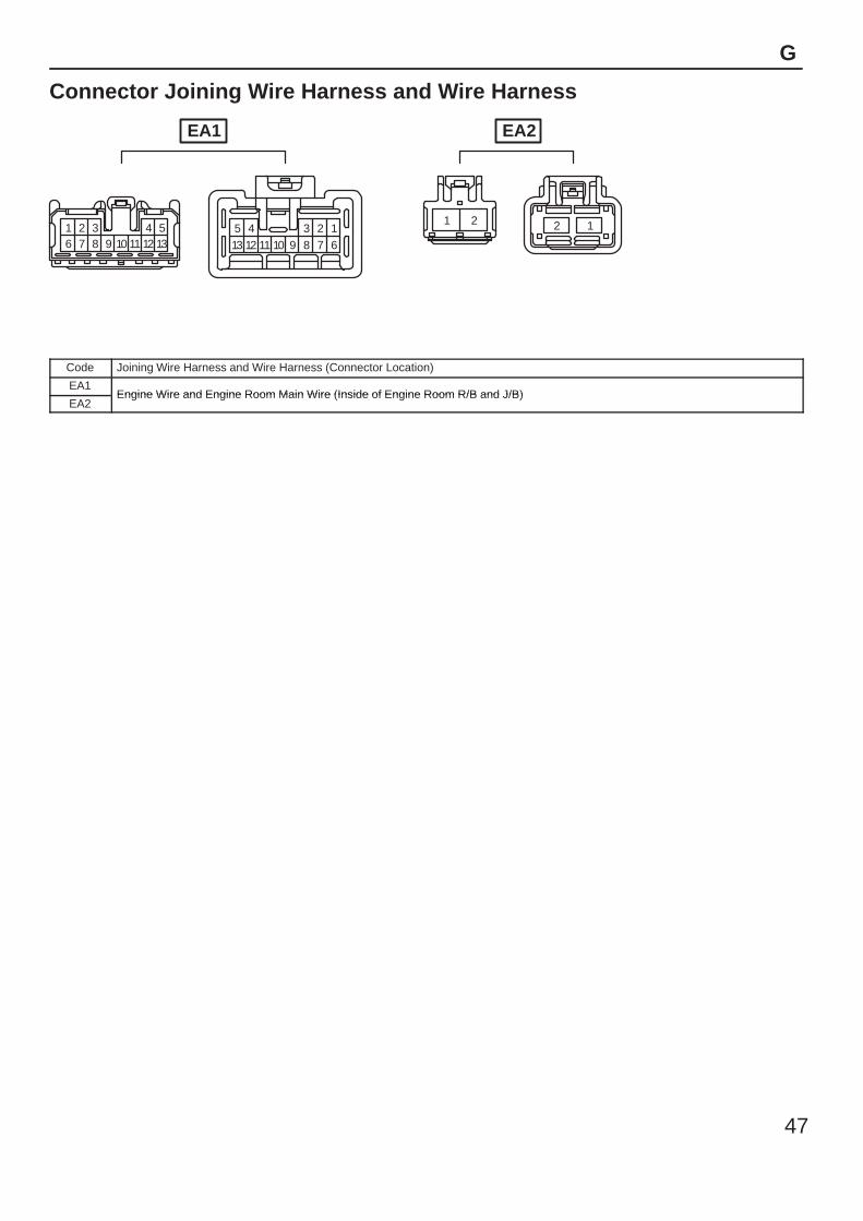
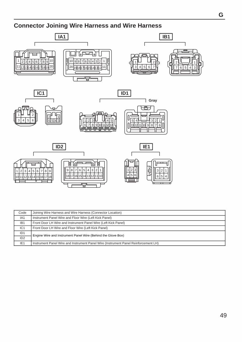
Connector Joining Wire Harness and Wire Harness
1 2 3 4 56 7 8 9 10 11 12 13
1234513 6789101112
1 2 2 1
EA1 EA2
Code Joining Wire Harness and Wire Harness (Connector Location)
EA1Engine Wire and Engine Room Main Wire (Inside of Engine Room R/B and J/B)
EA2Engine Wire and Engine Room Main Wire (Inside of Engine Room R/B and J/B)
48
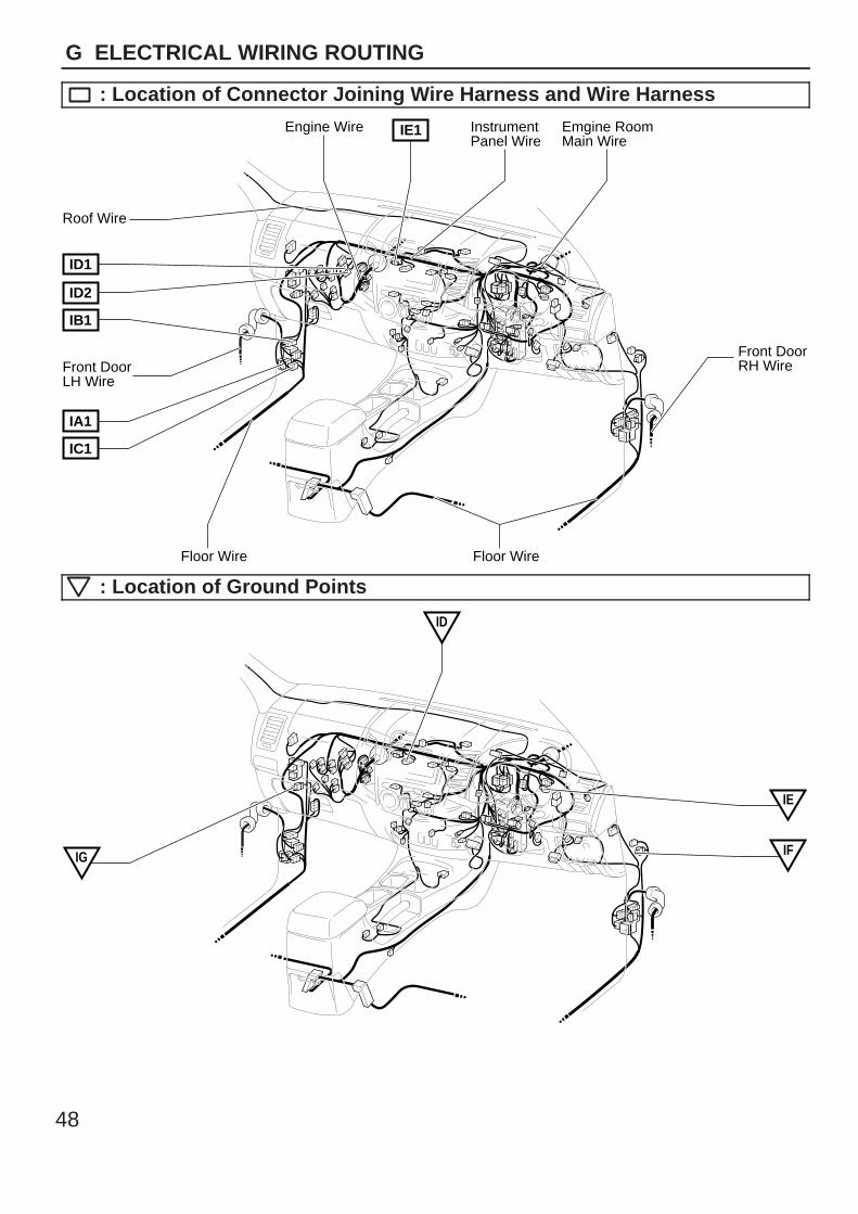
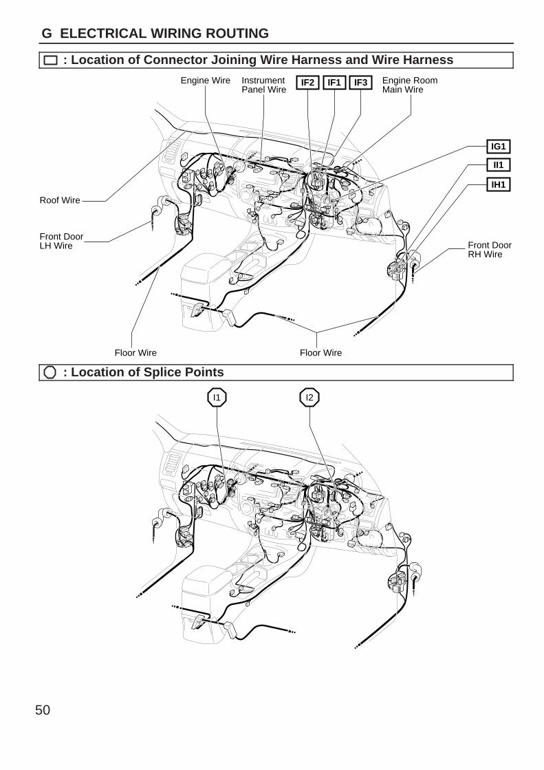
G ELECTRICAL WIRING ROUTING
: Location of Connector Joining Wire Harness and Wire Harness
Engine Wire InstrumentPanel Wire
Emgine RoomMain Wire
Front DoorRH Wire
Roof Wire
Front DoorLH Wire
IE1
Floor Wire
ID1
ID2
IB1
IA1
IC1
Floor Wire
: Location of Ground Points
ID
IF
IE
IG
49
G
Connector Joining Wire Harness and Wire Harness
1 2 3 4 5 6 7 8 9 10
11 1213141516171819 20
12345678910
111213141516171819202
7 6 5 4 3
121
3 4 5 6 7
123456
1 2
3 4 5 6
9
18
8
1716
76
1514
54
1312
32
11
1
10
89
18 17
7
16
6
15
5
14
4
13
3
12
2
11
1
10
1 2 3
4 5 6 6 5 4
3 2 1
1 2 3 4 56 7 8 9 10 11 12 13
12345
13 6789101112
IA1 IB1
IC1
ID2 IE1
ID1Gray
Code Joining Wire Harness and Wire Harness (Connector Location)
IA1 Instrument Panel Wire and Floor Wire (Left Kick Panel)
IB1 Front Door LH Wire and Instrument Panel Wire (Left Kick Panel)
IC1 Front Door LH Wire and Floor Wire (Left Kick Panel)
ID1Engine Wire and Instrument Panel Wire (Behind the Glove Box)
ID2Engine Wire and Instrument Panel Wire (Behind the Glove Box)
IE1 Instrument Panel Wire and Instrument Panel Wire (Instrument Panel Reinforcement LH)
50
G ELECTRICAL WIRING ROUTING
: Location of Connector Joining Wire Harness and Wire Harness
Engine Wire InstrumentPanel Wire
Engine RoomMain Wire
Front DoorRH Wire
Roof Wire
Front DoorLH Wire
IF2 IF1 IF3
Floor WireFloor Wire
IH1
II1
IG1
: Location of Splice Points
I1 I2
51
G
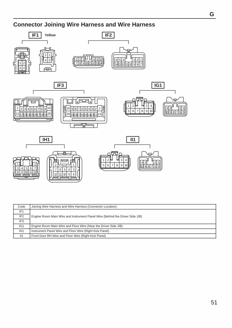
Connector Joining Wire Harness and Wire Harness
2 1
4 31 2
3 4
643217 8 9 10 11 12 14
513
23589101113
412
17
614
1 2 3 4 5 6 7 8 9 10
11 1213141516171819 20
12345678910
11121314151617181920
124567810
39
1 2
5
3 4
6 7 8 9 10
1 23 4 5 6 78 9 10 11 12
12
34567
89101112
124567810
39
1 2
5
3 4
6 7 8 9 10
IF1 Yellow IF2
IF3 IG1
IH1 II1
Code Joining Wire Harness and Wire Harness (Connector Location)
IF1
Engine Room Main Wire and Instrument Panel Wire (Behind the Driver Side J/B)IF2 Engine Room Main Wire and Instrument Panel Wire (Behind the Driver Side J/B)
IF3
IG1 Engine Room Main Wire and Floor Wire (Near the Driver Side J/B)
IH1 Instrument Panel Wire and Floor Wire (Right Kick Panel)
II1 Front Door RH Wire and Floor Wire (Right Kick Panel)
52
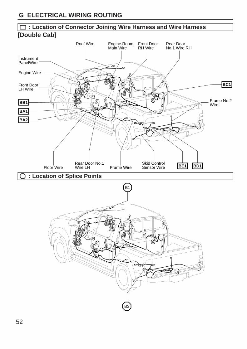
G ELECTRICAL WIRING ROUTING
: Location of Connector Joining Wire Harness and Wire Harness[Double Cab]
Roof Wire
Rear Door No.1Wire LH
Rear DoorNo.1 Wire RH
Front DoorRH Wire
Engine RoomMain Wire
Frame No.2Wire
Floor WireSkid ControlSensor WireFrame Wire
InstrumentPanelWire
Engine Wire
Front DoorLH Wire
BE1 BD1
BC1
BB1
BA1
BA2
: Location of Splice Points
B3
B1
53
G
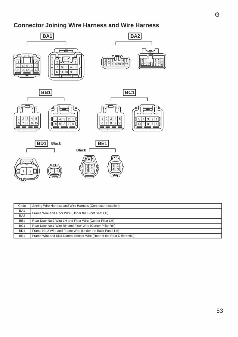
Connector Joining Wire Harness and Wire Harness
1 23 4 5 6 78 9 10 11 12
12
34567
89101112
543216 7 8 9 10 1112
2357891012
411
16
1 2 3 4 56 7 8 9 10
5 4 3 2 110 9 8 7 6
1 2 3 4 56 7 8 9 10
5 4 3 2 110 9 8 7 6
121 2
1 23 4
2 14 3
BA1
Black
BB1
BA2
BC1
BE1BD1Black
Code Joining Wire Harness and Wire Harness (Connector Location)
BA1Frame Wire and Floor Wire (Under the Front Seat LH)
BA2Frame Wire and Floor Wire (Under the Front Seat LH)
BB1 Rear Door No.1 Wire LH and Floor Wire (Center Pillar LH)
BC1 Rear Door No.1 Wire RH and Floor Wire (Center Pillar RH)
BD1 Frame No.2 Wire and Frame Wire (Under the Back Panel LH)
BE1 Frame Wire and Skid Control Sensor Wire (Rear of the Rear Differential)
54
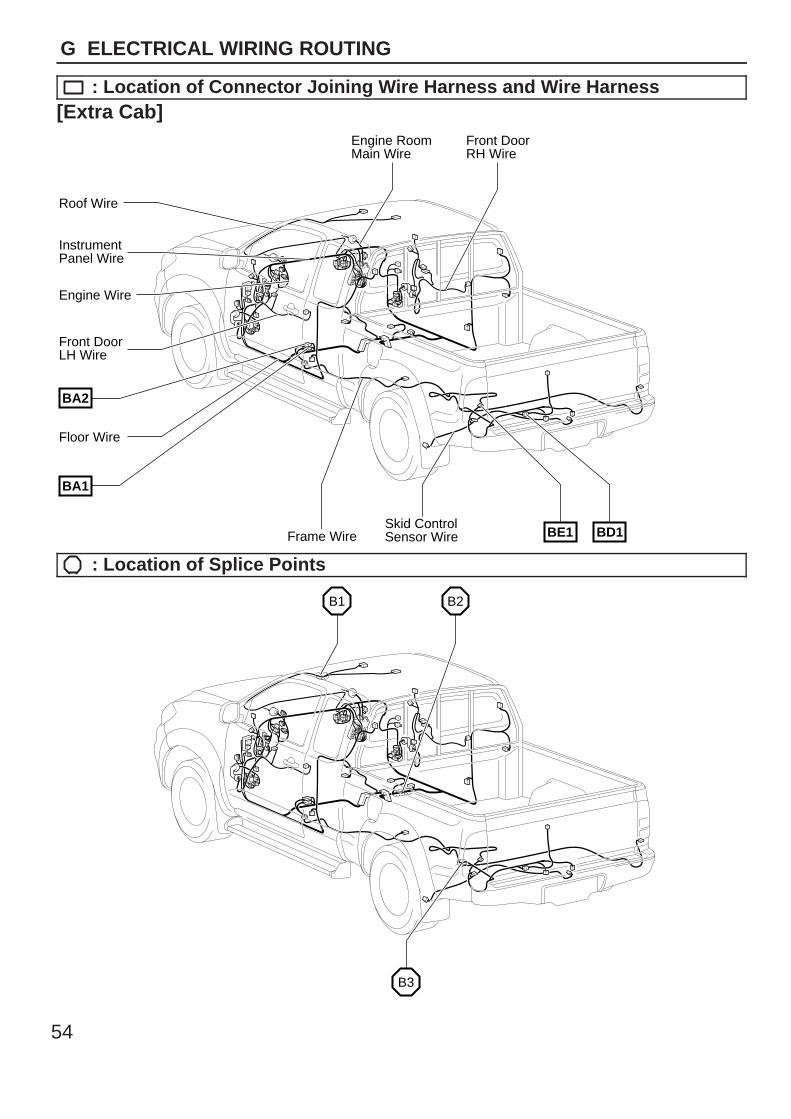
G ELECTRICAL WIRING ROUTING
: Location of Connector Joining Wire Harness and Wire Harness[Extra Cab]
Skid ControlSensor Wire
Front DoorRH Wire
Engine RoomMain Wire
Roof Wire
Engine Wire
InstrumentPanel Wire
Front DoorLH Wire
Floor Wire
BE1 BD1Frame Wire
BA2
BA1
: Location of Splice Points
B3
B1 B2

55
G
Connector Joining Wire Harness and Wire Harness
1 23 4 5 6 78 9 10 11 12
12
34567
89101112
543216 7 8 9 10 1112
2357891012
411
16
121 2
1 23 4
2 14 3
BA1 BA2
Black BE1BD1Black
Code Joining Wire Harness and Wire Harness (Connector Location)
BA1Frame Wire and Floor Wire (Under the Front Seat LH)
BA2Frame Wire and Floor Wire (Under the Front Seat LH)
BD1 Frame No.2 Wire and Frame Wire (Under the Back Panel LH)
BE1 Frame Wire and Skid Control Sensor Wire (Rear of the Rear Differential)
56
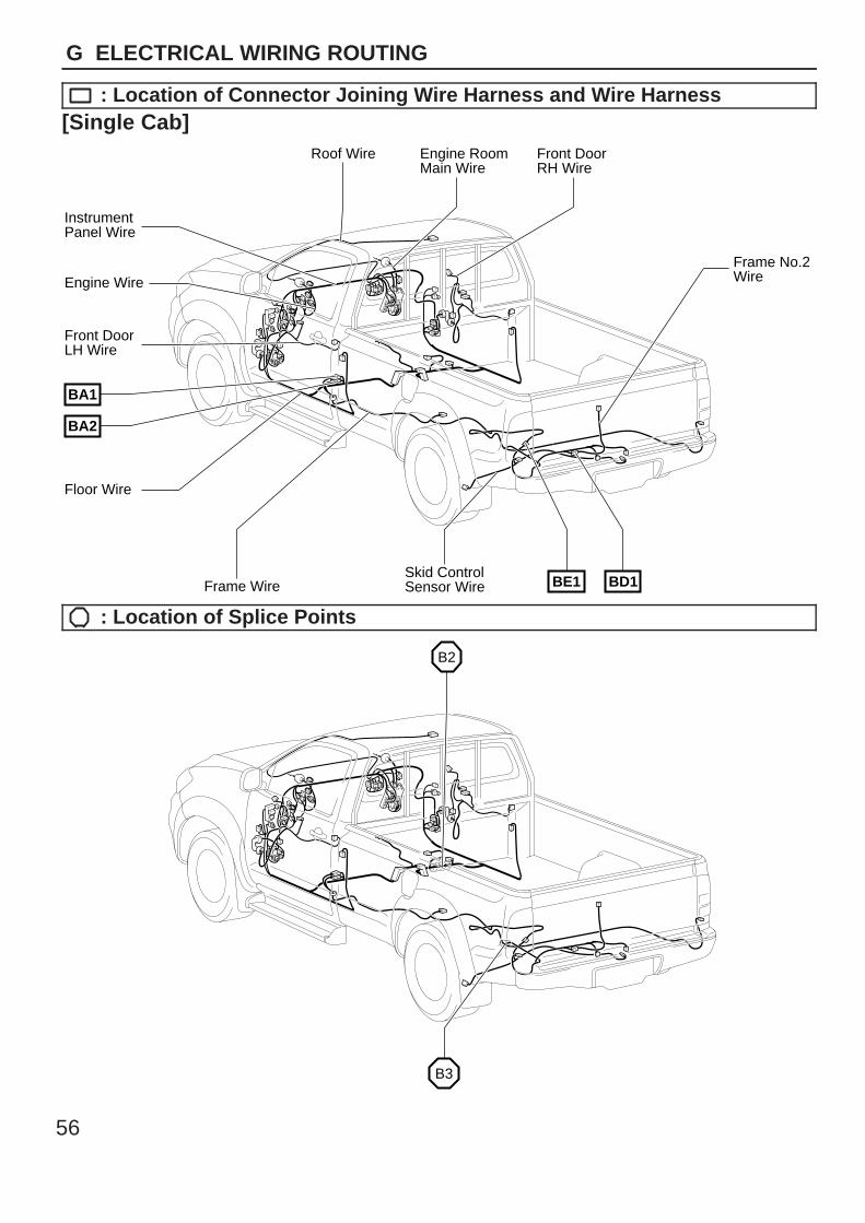
G ELECTRICAL WIRING ROUTING
: Location of Connector Joining Wire Harness and Wire Harness[Single Cab]
Roof Wire
Skid ControlSensor Wire
Front DoorRH Wire
Engine RoomMain Wire
Frame No.2Wire
InstrumentPanel Wire
Front DoorLH Wire
Engine Wire
Floor Wire
BE1 BD1Frame Wire
BA1
BA2
: Location of Splice Points
B3
B2
57
G
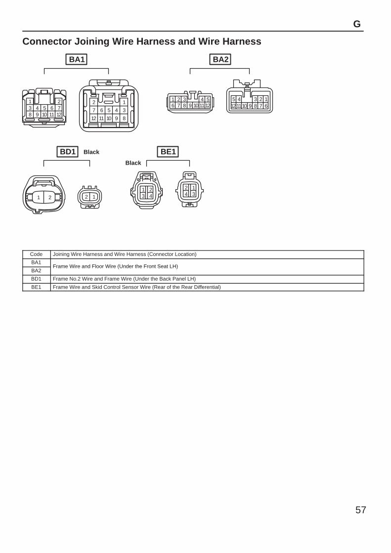
Connector Joining Wire Harness and Wire Harness
1 23 4 5 6 78 9 10 11 12
12
34567
89101112
543216 7 8 9 10 1112
2357891012
411
16
121 2
1 23 4
2 14 3
BA1 BA2
Black BE1BD1Black
Code Joining Wire Harness and Wire Harness (Connector Location)
BA1Frame Wire and Floor Wire (Under the Front Seat LH)
BA2Frame Wire and Floor Wire (Under the Front Seat LH)
BD1 Frame No.2 Wire and Frame Wire (Under the Back Panel LH)
BE1 Frame Wire and Skid Control Sensor Wire (Rear of the Rear Differential)

58
Memo
59
SYSTEM CIRCUITS H
HILUXELECTRICAL WIRING DIAGRAM
SYSTEM CIRCUITSPage
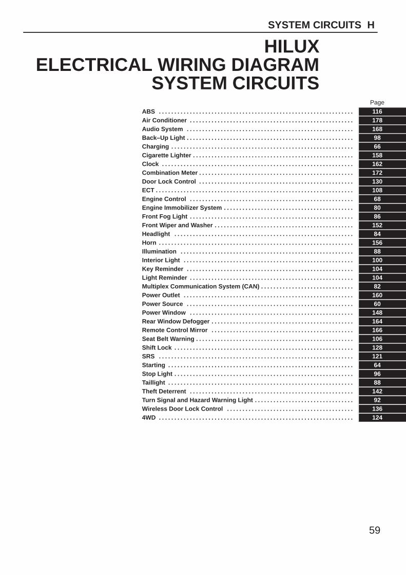
ABS . . . . . . . . . . . . . . . . . . . . . . . . . . . . . . . . . . . . . . . . . . . . . . . . . . . . . . . . . . . . . . . 116Air Conditioner . . . . . . . . . . . . . . . . . . . . . . . . . . . . . . . . . . . . . . . . . . . . . . . . . . . . . 178Audio System . . . . . . . . . . . . . . . . . . . . . . . . . . . . . . . . . . . . . . . . . . . . . . . . . . . . . . 168Back–Up Light . . . . . . . . . . . . . . . . . . . . . . . . . . . . . . . . . . . . . . . . . . . . . . . . . . . . . . 98Charging . . . . . . . . . . . . . . . . . . . . . . . . . . . . . . . . . . . . . . . . . . . . . . . . . . . . . . . . . . . 66Cigarette Lighter . . . . . . . . . . . . . . . . . . . . . . . . . . . . . . . . . . . . . . . . . . . . . . . . . . . . 158Clock . . . . . . . . . . . . . . . . . . . . . . . . . . . . . . . . . . . . . . . . . . . . . . . . . . . . . . . . . . . . . . 162Combination Meter . . . . . . . . . . . . . . . . . . . . . . . . . . . . . . . . . . . . . . . . . . . . . . . . . . 172Door Lock Control . . . . . . . . . . . . . . . . . . . . . . . . . . . . . . . . . . . . . . . . . . . . . . . . . . 130ECT . . . . . . . . . . . . . . . . . . . . . . . . . . . . . . . . . . . . . . . . . . . . . . . . . . . . . . . . . . . . . . . . 108Engine Control . . . . . . . . . . . . . . . . . . . . . . . . . . . . . . . . . . . . . . . . . . . . . . . . . . . . . 68Engine Immobilizer System . . . . . . . . . . . . . . . . . . . . . . . . . . . . . . . . . . . . . . . . . . 80Front Fog Light . . . . . . . . . . . . . . . . . . . . . . . . . . . . . . . . . . . . . . . . . . . . . . . . . . . . . 86Front Wiper and Washer . . . . . . . . . . . . . . . . . . . . . . . . . . . . . . . . . . . . . . . . . . . . . 152Headlight . . . . . . . . . . . . . . . . . . . . . . . . . . . . . . . . . . . . . . . . . . . . . . . . . . . . . . . . . . 84Horn . . . . . . . . . . . . . . . . . . . . . . . . . . . . . . . . . . . . . . . . . . . . . . . . . . . . . . . . . . . . . . . 156Illumination . . . . . . . . . . . . . . . . . . . . . . . . . . . . . . . . . . . . . . . . . . . . . . . . . . . . . . . . 88Interior Light . . . . . . . . . . . . . . . . . . . . . . . . . . . . . . . . . . . . . . . . . . . . . . . . . . . . . . . 100Key Reminder . . . . . . . . . . . . . . . . . . . . . . . . . . . . . . . . . . . . . . . . . . . . . . . . . . . . . . 104Light Reminder . . . . . . . . . . . . . . . . . . . . . . . . . . . . . . . . . . . . . . . . . . . . . . . . . . . . . 104Multiplex Communication System (CAN) . . . . . . . . . . . . . . . . . . . . . . . . . . . . . . 82Power Outlet . . . . . . . . . . . . . . . . . . . . . . . . . . . . . . . . . . . . . . . . . . . . . . . . . . . . . . . 160Power Source . . . . . . . . . . . . . . . . . . . . . . . . . . . . . . . . . . . . . . . . . . . . . . . . . . . . . . 60Power Window . . . . . . . . . . . . . . . . . . . . . . . . . . . . . . . . . . . . . . . . . . . . . . . . . . . . . 148Rear Window Defogger . . . . . . . . . . . . . . . . . . . . . . . . . . . . . . . . . . . . . . . . . . . . . . 164Remote Control Mirror . . . . . . . . . . . . . . . . . . . . . . . . . . . . . . . . . . . . . . . . . . . . . . 166Seat Belt Warning . . . . . . . . . . . . . . . . . . . . . . . . . . . . . . . . . . . . . . . . . . . . . . . . . . . 106Shift Lock . . . . . . . . . . . . . . . . . . . . . . . . . . . . . . . . . . . . . . . . . . . . . . . . . . . . . . . . . . 128SRS . . . . . . . . . . . . . . . . . . . . . . . . . . . . . . . . . . . . . . . . . . . . . . . . . . . . . . . . . . . . . . . 121Starting . . . . . . . . . . . . . . . . . . . . . . . . . . . . . . . . . . . . . . . . . . . . . . . . . . . . . . . . . . . . 64Stop Light . . . . . . . . . . . . . . . . . . . . . . . . . . . . . . . . . . . . . . . . . . . . . . . . . . . . . . . . . . 96Taillight . . . . . . . . . . . . . . . . . . . . . . . . . . . . . . . . . . . . . . . . . . . . . . . . . . . . . . . . . . . . 88Theft Deterrent . . . . . . . . . . . . . . . . . . . . . . . . . . . . . . . . . . . . . . . . . . . . . . . . . . . . . 142Turn Signal and Hazard Warning Light . . . . . . . . . . . . . . . . . . . . . . . . . . . . . . . . 92Wireless Door Lock Control . . . . . . . . . . . . . . . . . . . . . . . . . . . . . . . . . . . . . . . . . 1364WD . . . . . . . . . . . . . . . . . . . . . . . . . . . . . . . . . . . . . . . . . . . . . . . . . . . . . . . . . . . . . . . 124
60
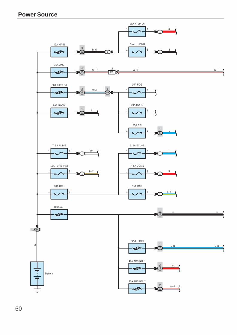
Power Source
1A1
Battery
W
30A AM2
1B4
50A BATT P/I
1B3
80A GLOW
1G1
40A MAIN
1C3 1 2
20A H–LP LH
1 2
20A H–LP RH
1
1
1B
R
B–W
W–R
W–L
B
1 2
15A FOG
1 2
10A HORN
1H
21
1
25A EFI
1JL
40A ABS NO. 1
1B2 R
30A ABS NO. 2
1C2 W–R
40A FR HTR
1C1 L–B
1F1
100A ALT
W–R
30A DCC
1 2
W1
21
7. 5A ALT–S
1B–Y1 2
15A TURN–HAZ
21
7. 5A ECU–B
21
L–Y
7. 5A DOME
1
1R
21
L1
15A RAD
B
W–R
B
L–B
1
IF311
61
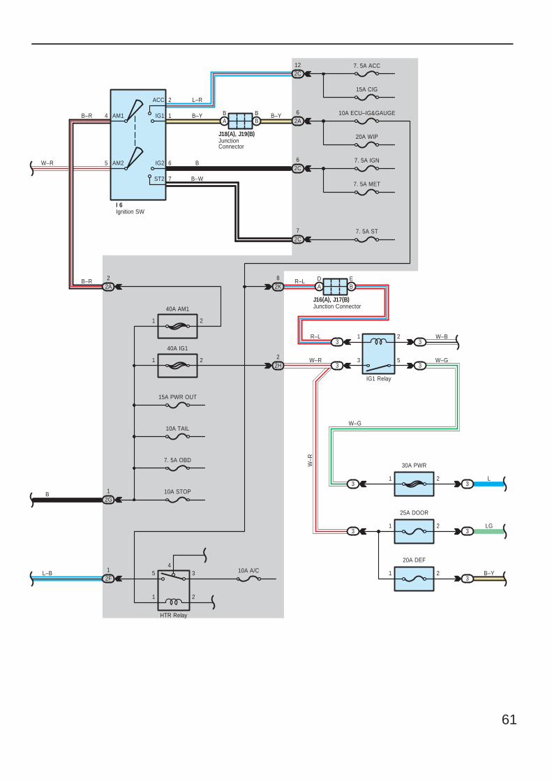
4
5
2
1
6
7
AM2
AM1
ACC
IG1
IG2
ST2
L–R
B–YB–R
B
B–W
I 6
AB
BB
J18(A), J19(B)
7. 5A ACC
15A CIG
2C12
2G1
2F1 5
1
3
2
410A A/C
HTR Relay
1 2
40A AM1
1 2
40A IG1
10A STOP
7. 5A OBD
10A TAIL
15A PWR OUT
10A ECU–IG&GAUGE
20A WIP
2A6B–Y
2A2B–R
7. 5A IGN
7. 5A MET
2C6
7. 5A ST2C7
L–B
B
W–R
2H2
1
3
2
5
3
3
3
3
30A PWR
21 L3
25A DOOR
21 LG3
20A DEF
21 B–Y3
3
3
R–L W–B
W–G
W–G
W–R
W–R
IG1 Relay
2K8
AD
BER–L
J16(A), J17(B)
Ignition SW
Junction Connector
JunctionConnector
62
Power Source
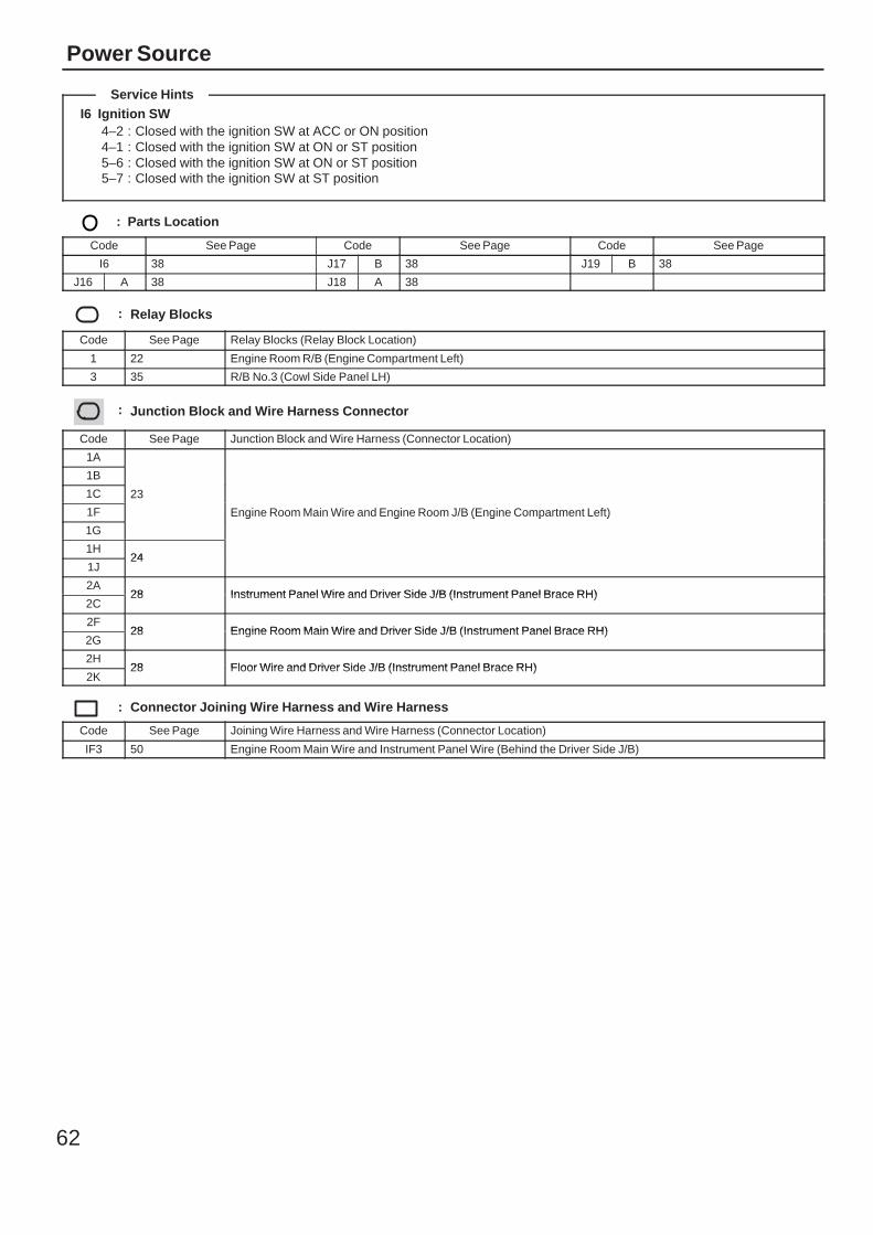
I6 Ignition SW4–2 : Closed with the ignition SW at ACC or ON position4–1 : Closed with the ignition SW at ON or ST position5–6 : Closed with the ignition SW at ON or ST position5–7 : Closed with the ignition SW at ST position
: Parts Location
Code See Page Code See Page Code See Page
I6 38 J17 B 38 J19 B 38
J16 A 38 J18 A 38
: Relay Blocks
Code See Page Relay Blocks (Relay Block Location)
1 22 Engine Room R/B (Engine Compartment Left)
3 35 R/B No.3 (Cowl Side Panel LH)
: Junction Block and Wire Harness Connector
Code See Page Junction Block and Wire Harness (Connector Location)
1A
23
Engine Room Main Wire and Engine Room J/B (Engine Compartment Left)
1B
23
Engine Room Main Wire and Engine Room J/B (Engine Compartment Left)
1C 23
Engine Room Main Wire and Engine Room J/B (Engine Compartment Left)1F
23
Engine Room Main Wire and Engine Room J/B (Engine Compartment Left)
1G
Engine Room Main Wire and Engine Room J/B (Engine Compartment Left)
1H24
1J24
2A28 Instrument Panel Wire and Driver Side J/B (Instrument Panel Brace RH)
2C28 Instrument Panel Wire and Driver Side J/B (Instrument Panel Brace RH)
2F28 Engine Room Main Wire and Driver Side J/B (Instrument Panel Brace RH)
2G28 Engine Room Main Wire and Driver Side J/B (Instrument Panel Brace RH)
2H28 Floor Wire and Driver Side J/B (Instrument Panel Brace RH)
2K28 Floor Wire and Driver Side J/B (Instrument Panel Brace RH)
: Connector Joining Wire Harness and Wire Harness
Code See Page Joining Wire Harness and Wire Harness (Connector Location)
IF3 50 Engine Room Main Wire and Instrument Panel Wire (Behind the Driver Side J/B)
Service Hints

63
Memo
64
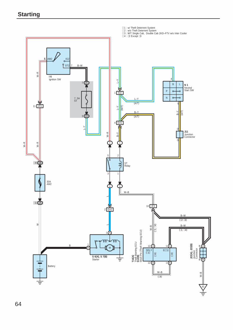
Starting
Battery
A1
B1
STRelay
W–R
5
4
P
N
1
2
3
5
B–Y
B–Y
L–Y
LL
L–Y
( M/T
)
W–R
7. 5AST
5
W
30AAM2
W–R
B–W
L–Y
W–B
W–B
W–B
W–B
( ∗4)
(∗4)
( ∗4)
E(∗1)SRLY(∗1)
(A/T)
B–Y
∗ 1 : w/ Theft Deterrent System∗ 2 : w/o Theft Deterrent System
(A/T)
L–Y
B L
5
7
AM2 IG2
ST2
I 6
1B4
1A1
2O3
1 1
1 1
2C7
EA22
ID21
EA14
IF310
S 6(A), S 7(B)
M
J11
( A/T
)
N 1
B12
1 A12 A
B1
S12(
B)
T16(
A)
AB
BB
ID
Ignition SW
JunctionConnector
NeutralStart SW
Starter
Sho
rt P
in (
Thef
t War
ning
EC
U)
IF311
D
D
∗ 3 : M/T Single Cab, Double Cab 2KD–FTV w/o Inter Cooler∗ 4 : ∗2 Except ∗3
W–R
Junc
tion
Con
nect
or
J22(
A), J
23( B
)
B–W
B–W
(∗2 ∗3)
( ∗1,
∗4)
(∗1, ∗4)
Thef
t War
ning
EC
U
B
65
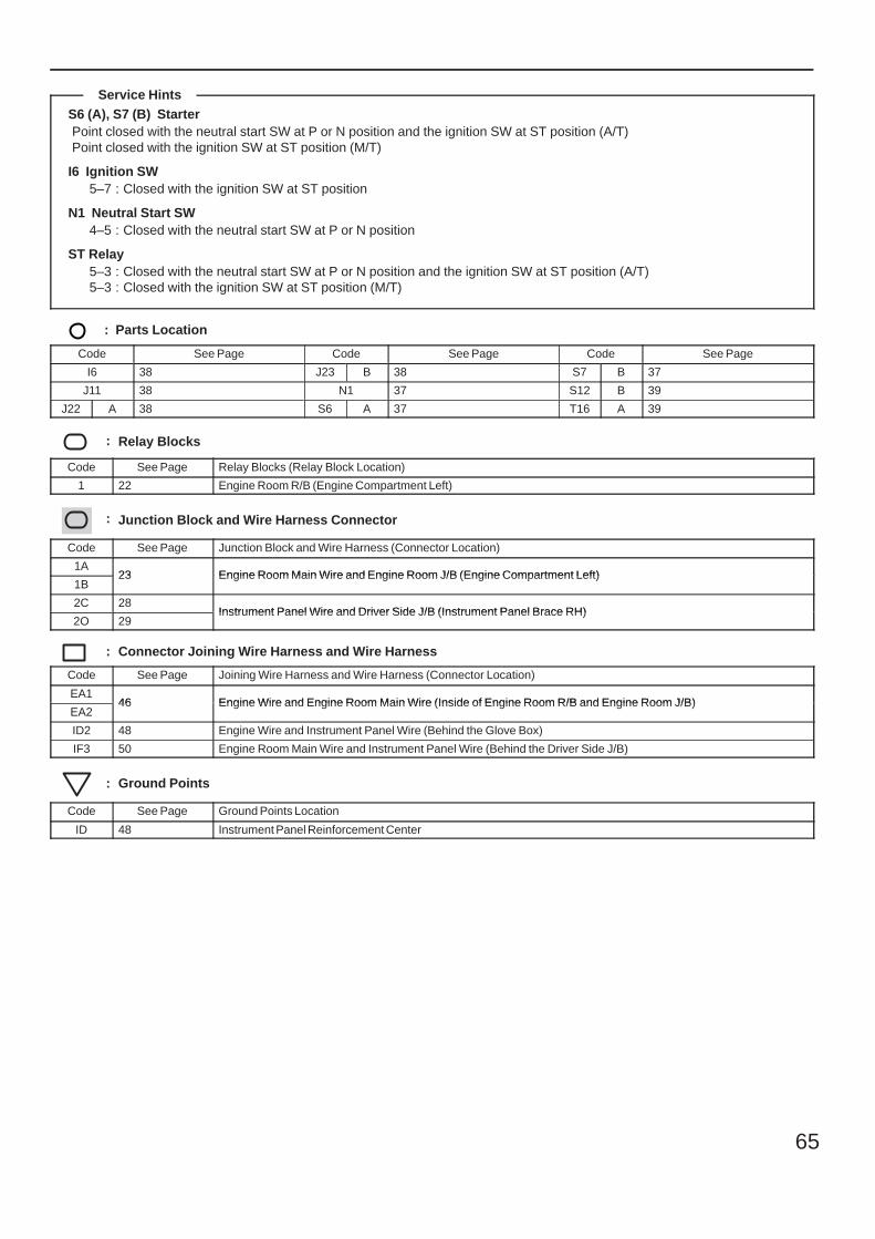
S6 (A), S7 (B) StarterPoint closed with the neutral start SW at P or N position and the ignition SW at ST position (A/T)Point closed with the ignition SW at ST position (M/T)
I6 Ignition SW5–7 : Closed with the ignition SW at ST position
N1 Neutral Start SW4–5 : Closed with the neutral start SW at P or N position
ST Relay5–3 : Closed with the neutral start SW at P or N position and the ignition SW at ST position (A/T)5–3 : Closed with the ignition SW at ST position (M/T)
: Parts Location
Code See Page Code See Page Code See Page
I6 38 J23 B 38 S7 B 37
J11 38 N1 37 S12 B 39
J22 A 38 S6 A 37 T16 A 39
: Relay Blocks
Code See Page Relay Blocks (Relay Block Location)
1 22 Engine Room R/B (Engine Compartment Left)
: Junction Block and Wire Harness Connector
Code See Page Junction Block and Wire Harness (Connector Location)
1A23 Engine Room Main Wire and Engine Room J/B (Engine Compartment Left)
1B23 Engine Room Main Wire and Engine Room J/B (Engine Compartment Left)
2C 28Instrument Panel Wire and Driver Side J/B (Instrument Panel Brace RH)
2O 29Instrument Panel Wire and Driver Side J/B (Instrument Panel Brace RH)
: Connector Joining Wire Harness and Wire Harness
Code See Page Joining Wire Harness and Wire Harness (Connector Location)
EA146 Engine Wire and Engine Room Main Wire (Inside of Engine Room R/B and Engine Room J/B)
EA246 Engine Wire and Engine Room Main Wire (Inside of Engine Room R/B and Engine Room J/B)
ID2 48 Engine Wire and Instrument Panel Wire (Behind the Glove Box)
IF3 50 Engine Room Main Wire and Instrument Panel Wire (Behind the Driver Side J/B)
: Ground Points
Code See Page Ground Points Location
ID 48 Instrument Panel Reinforcement Center
Service Hints
66
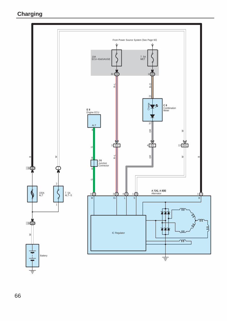
Charging
W
B–O
BWGR
R–L
GR
WB
Battery
R–L
100AALT
W
1
2
7. 5AALT–S
Cha
rge
37
21
IG L S B
IC Regulator
B2 B4 B1 A1
7. 5AMET
2D1
10AECU–IG&GAUGE
From Power Source System (See Page 60)
2S32
EA113ID24ID23
1A1
1E1 1
M
B3
B
B
ALT
GG
E 8
J 6
A 7(A), A 8(B)
C 8
Alternator
CombinationMeter
Engine ECU
JunctionConnector
8
67
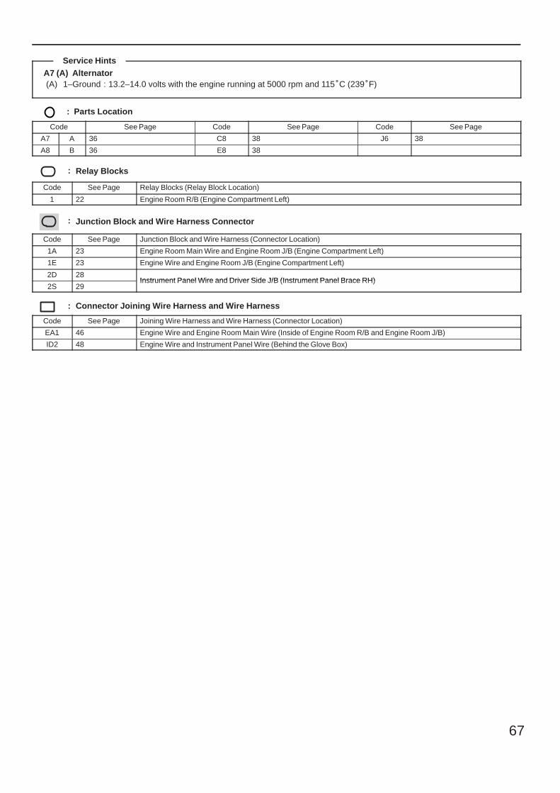
A7 (A) Alternator(A) 1–Ground : 13.2–14.0 volts with the engine running at 5000 rpm and 115C (239F)
: Parts Location
Code See Page Code See Page Code See Page
A7 A 36 C8 38 J6 38
A8 B 36 E8 38
: Relay Blocks
Code See Page Relay Blocks (Relay Block Location)
1 22 Engine Room R/B (Engine Compartment Left)
: Junction Block and Wire Harness Connector
Code See Page Junction Block and Wire Harness (Connector Location)
1A 23 Engine Room Main Wire and Engine Room J/B (Engine Compartment Left)
1E 23 Engine Wire and Engine Room J/B (Engine Compartment Left)
2D 28Instrument Panel Wire and Driver Side J/B (Instrument Panel Brace RH)
2S 29Instrument Panel Wire and Driver Side J/B (Instrument Panel Brace RH)
: Connector Joining Wire Harness and Wire Harness
Code See Page Joining Wire Harness and Wire Harness (Connector Location)
EA1 46 Engine Wire and Engine Room Main Wire (Inside of Engine Room R/B and Engine Room J/B)
ID2 48 Engine Wire and Instrument Panel Wire (Behind the Glove Box)
Service Hints
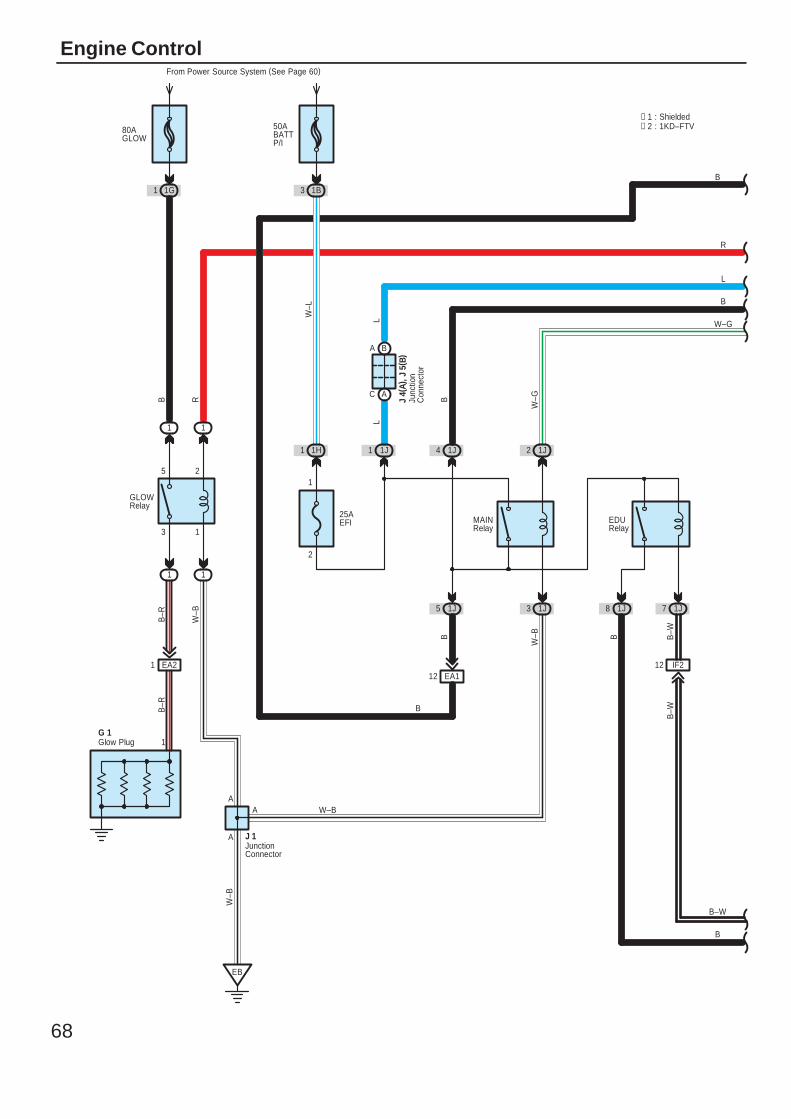
68
Engine Control
50ABATTP/I
From Power Source System (See Page 60)
1B3
W–L
A
A
B
1
25AEFI
L
L
EDURelay
2
B
L
W–G
W–BB
B–R
W–B
R
B–W
B–W
B–W
W–G
B
B
1
2
3
5
GLOWRelay
B–R
W–B
B R
1
W–B
B
A
EB
G 1
J 1
11
11
1J5 1J3 1J8 1J7
1H1 1J1 1J4 1J2
EA21EA112
IF212
J 4(
A), J
5( B
)
BA
AC
80AGLOW
1G1
MAINRelay
B
Glow Plug
JunctionConnector
Junc
tion
Con
nect
or
∗ 1 : Shielded∗ 2 : 1KD–FTV
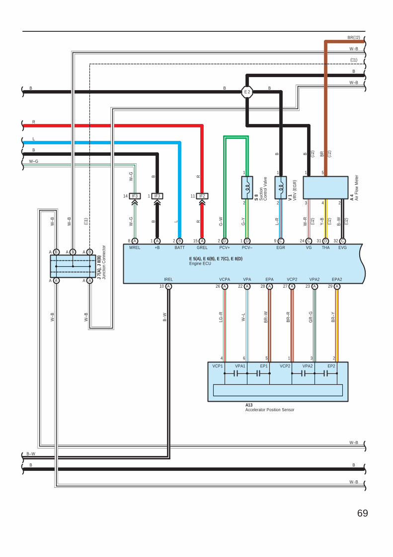
69
E 5(A), E 6(B), E 7(C), E 8(D)
R
B–W
L
R
W–G
B
G–W
G–Y
PCV+
1
2
PCV–GREL
R
BB
W–G B
W–G
+BMREL BATT
B–W
IREL
L
B
A10
IF314 IF31 IF211
A15B2A1A8 D2 D1
29 A23 A27 A28 AA22
VCPA
LG–R
W–L
VPA EPA
BR
–W
BR
–R
VCP2
BR
–Y
EPA2VPA2
GR
–G
26 A
A13
4 6 5 1 3 2
B
B
B
W–B
Accelerator Position Sensor
Engine ECU
A B
A AL–
R
EGR
B
B
C9
E 2
1
2
VR
V (
EG
R)
V 1
Suc
tion
Con
trol V
alve
S 8
(∗1)
W–B
A B A B
A A
Junc
tion
Con
nect
orJ
7(A)
, J 8
( B)
W–B
W–B
W–B
W–B
W–B
( ∗1)
C24 D31 C32
VG THA EVG
3 4 2
1
B ( ∗2)
W–R
( ∗2)
Y–B ( ∗2)
B–W ( ∗2)
Air
Flow
Met
erA
4
BR(∗2)
( ∗2)
BR
W–B
5
EP2VPA2VCP2EP1VPA1VCP1
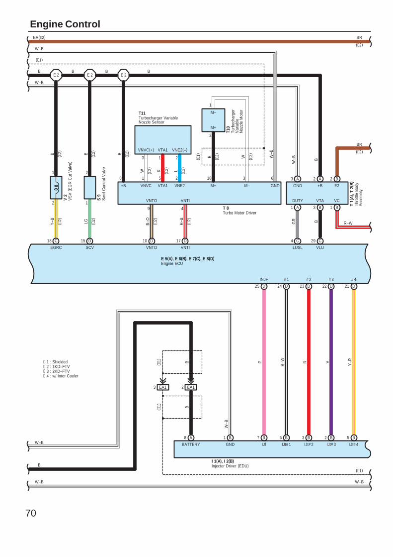
70
Engine ControlBR
E 5(A), E 6(B), E 7(C), E 8(D)
B
B
W–B
2 EA1
21 D22 D23 D24 D25 D
5 B2 B3 B6 B7 B8 A 1 B
I 1(A), I 2(B)
W–B
GND
B( ∗1)
( ∗1)
EA1
# 2
IJt# 2 IJt# 3
# 3
V
Y–R
# 4
IJt# 4
R
3
# 1
IJt# 1
B–W
INJF
IJf
P
BATTERY
B
(∗1)
W–B
∗ 1 : Shielded
Engine ECU
Injector Driver (EDU)
∗ 2 : 1KD–FTV∗ 3 : 2KD–FTV∗ 4 : w/ Inter Cooler
LGB
SCV
15 D
2
1
S 9
Y–B
B
EGRC
18 C
1
2
V 2
E 2 E 2B B
( ∗2)
( ∗2)
(∗2)
( ∗2)
( ∗2)
R–B
W–B
VNTI
17 D
6
4
( ∗2)
B–O
VNTO
10 D
9
( ∗2)
T 8
T11
3102518
+B
VNTO
VTA1
VNTI
VNVC VNE2 M+ GNDM–
W ( ∗2)B ( ∗2)
L ( ∗2)R ( ∗2)W ( ∗2)
( ∗1)
3
VNVC(+)
1
VTA1
2
VNE2(–)
2
1
T10
(∗1)
W–B
W–B
( ∗2)B
M–
M+
Turbocharger VariableNozzle Sensor
Turbo Motor Driver
VS
V (
EG
R C
ut V
alve
)
Sw
irl C
ontro
l Val
ve
Turb
ocha
rger
Var
iabl
eN
ozzl
e M
otor
BR(∗2)
C4 C29
LUSL VLU
A1 B3 B1
A3 A2 B2
(∗2)
BR
R–W
E 2
W–B
W–B B
GR B
DUTY VTA VC
GND +B E2
Thro
ttle
Bod
yA
ssem
bly
T 1(
A), T
2( B
)
B
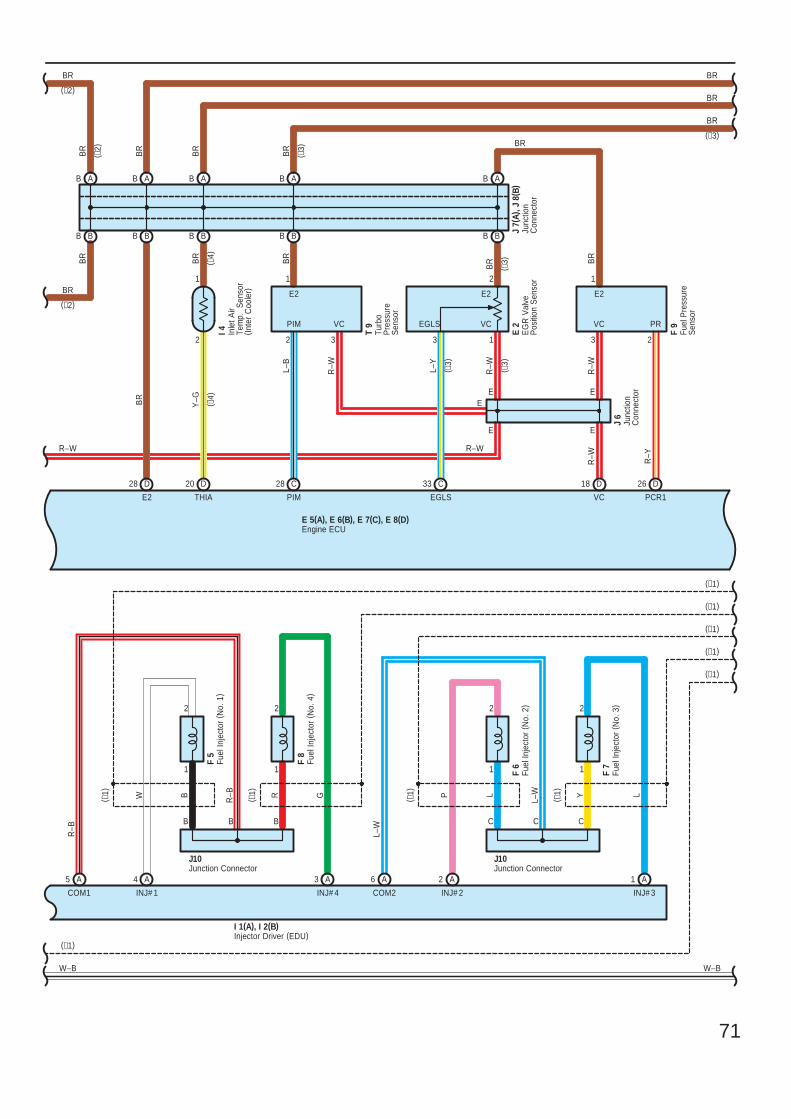
71
B
E 5(A), E 6(B), E 7(C), E 8(D)
BR
BR
F 7
5 A A4 3 A 6 A 2 A 1 A
F 5
F 8
F 6
I 1(A), I 2(B)
2
1
B
2
1
R
J10
2
1
L
2
1
Y
J10
P LGW L–W
L–W
R–B
R–B
COM1 INJ# 1 INJ# 4 INJ# 2 INJ# 3
( ∗1)
( ∗1)
( ∗1)
( ∗1)
COM2
BR
B B
BA B
B
BR
VC
R–W
PR
E2
BR
R–Y
VCPIM
E2
R–W
VC
BR
L–B
PIM
B
PCR1
BR
A
E2
BR
BR
B
B
1
A
1
BB B
THIA
BR
Y–G
1
D26D1828 CD20D28
E
2 2 3 3 2
E
B
(∗1)
(∗1)
(∗1)
(∗1)
W–B
( ∗3)
(∗1)
W–B
Engine ECU
Fuel
Inje
ctor
(N
o. 1
)
Fuel
Inje
ctor
(N
o. 2
)
Fuel
Inje
ctor
(N
o. 3
)
Fuel
Inje
ctor
(N
o. 4
)
BR
Injector Driver (EDU)
Junction Connector Junction Connector
E
BR
(∗3)
I 4 Fuel
Pre
ssur
eS
enso
r
F 9
Turb
oP
ress
ure
Sen
sor
T 9
A
BR
( ∗2)
BR
A
(∗2)
(∗1)
( ∗4)
CCCBBB
Inle
t Air
Tem
p.
Sen
sor
( Inte
r C
oole
r)
( ∗4)
(∗2)
BR
R–W R–W
Junc
tion
Con
nect
or
J 7(
A), J
8( B
)
E
Junc
tion
Con
nect
or
J 6
R–W
E
E 2
EG
R V
alve
Pos
ition
Sen
sor
BB
C33
EGLSB
R
( ∗3)
R–W ( ∗3)
L–Y
( ∗3)
2
3 1
E2
EGLS VC
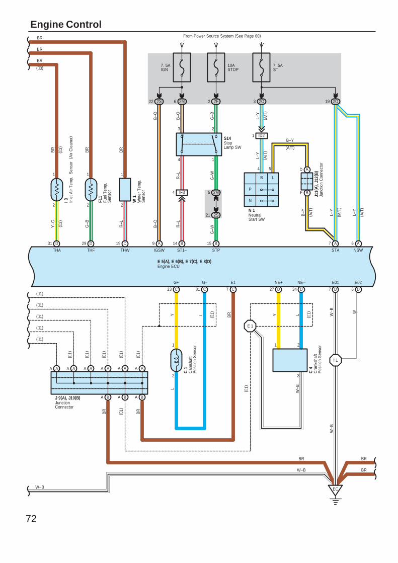
72
Engine Control
A AAAA AAA
A BBA
A
AJ 9(A), J10(B)
BR
( ∗1)
( ∗1)
( ∗1)
( ∗1)
( ∗1)
( ∗1)
A
B
A A
BR
BR
G–B
BR
THF
R–L
BR
THW
19 DD29
11
22
JunctionConnector
( A/T
)
B–Y
C7
D A
F B
BR
N 1
L–Y
STA
L–Y
7. 5AST
2O3
L–Y
54
P
N
A7
( A/T
)( A
/T)
1 ID2
(A/T)
B–Y
2O19
( M/T
)
J11(
A), J
12( B
)
23 C 31 C 27 D 34 D
E 1
EC
7 D 6 D
I 1
From Power Source System (See Page 60)
E 5(A), E 6(B), E 7(C), E 8(D)
BR
W–B
E02
BR
E01
W–B W
NE+
( ∗1)
G+
2
1
G–
W–B
1
Y L
NE–
2
3
Y L
E1
BR
1
2
2F2
2M
G–W
G–B
21
5
2S
S14
15 B
4 IF3
STP
G–W
3
4
R–L
R–L
14
ST1–
A9 B
IGSW
B–O
2S22
B–O
B–O
6 2M
7. 5AIGN
(∗1)
(∗1)
(∗1)
(∗1)
W–B
W–B
B L
Engine ECU
Junc
tion
Con
nect
or
NeutralStart SW
StopLamp SW
Cam
shaf
tP
ositi
on S
enso
r
C 1
Cra
nksh
aft
Pos
ition
Sen
sor
C 4
( ∗1)
( ∗1)
Wat
er T
emp.
S
enso
r
W 1
Fuel
Tem
p.
Sen
sor
F11
Y–G
BR
THA
D31
1
2
I 3( ∗
3)
BR
( ∗3)
(∗3)
(∗1)
BR
L
( A/T
)
6 A
NSW
L–Y
10ASTOP
Inle
t Air
Tem
p.
Sen
sor
(A
ir C
lean
er)
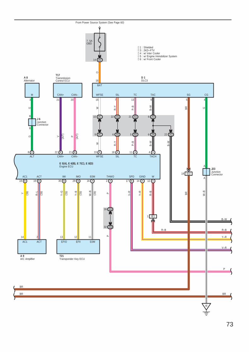
73
B
14
29
2 13
Y–G
14 2D
From Power Source System (See Page 60)
7. 5AOBD
219
2N
E 5(A), E 6(B), E 7(C), E 8(D)
AB
18
6
B18
P
18 A 11 A19
9
B–W
A
A
Y
P
THWO
PR–L
AC1 ACT
V–R
SPD
J 6
∗ 3 : 2KD–FTV
A
TACH
SIL
7
TC
13
ID2
SIL
A
TC
BAT
O
16
W–B
G
6 2O
W
WFSE
4
WFSE
15
BR
CG
45
SG
R–Y
P–B
BR
GG
M
3
ALT
D8
A 8( A
/T)
( A/T
)
B17
IE
D 1
B–W
TAC
T17
22
P
CAN–
20
B
CAN+
21
CAN+
V
2Q21
2Q5
2Q22
2Q6
R–Y
P–B
12 A
1 IE1
W
R–B
2O22
B–W
2Q16
2Q32
B30
12
A 9
ACTAC1
CAN–
B21
B–W
R–B
V–R
BR
W
9 2C
10 2CB
B
Y–R
GIND
A14
Y–R
J23
BR
BR
∗ 1 : Shielded
R–B
Y–B
Alternator
A/C Amplifier
DLC3
Engine ECU
JunctionConnector
JunctionConnector
TransmissionControl ECU
IMI IMO
T21
EFIIEFIO
Transponder Key ECU
A16
11
W–B
E0M
E0M
∗ 4 : w/ Inter Cooler∗ 5 : w/ Engine Immobilizer System
( ∗5)
( ∗5)
( ∗5)
∗ 6 : w/ Front Cooler
( ∗6)
( ∗6)
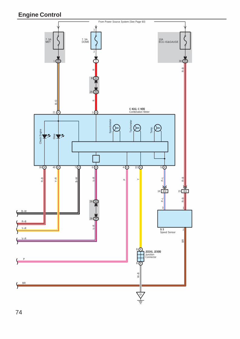
74
Engine Control
Glo
wB
–O
7. 5AMET
2D1
2
1
From Power Source System (See Page 60)
7. 5ADOME
30 2S
10AECU–IG&GAUGE
25 2Q
8 2J
1
1 A
R
B–W
Spe
edom
eter
Tach
omet
er
Tem
p.
P P–L
BR
P–L
2
3
RV
–RV
–R
R–B
2Q26
2P26
ID216
A4A7 A5A6
C 8(A), C 9(B)
40 A
Y–R
A21
15 ID2
1
R–B
R–B
B–W
R–B
V–R
BR
S 3
P
Che
ck E
ngin
eR
–B
A39
Y–R
YW
–B
ID
A22
J22(A), J23(B)AB
BB
Combination Meter
JunctionConnector
Speed Sensor
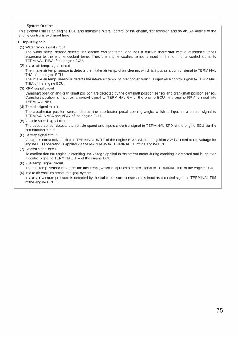
75
This system utilizes an engine ECU and maintains overall control of the engine, transmission and so on. An outline of theengine control is explained here.
1. Input Signals(1) Water temp. signal circuit
The water temp. sensor detects the engine coolant temp. and has a built–in thermistor with a resistance variesaccording to the engine coolant temp. Thus the engine coolant temp. is input in the form of a control signal toTERMINAL THW of the engine ECU.
(2) Intake air temp. signal circuitThe intake air temp. sensor is detects the intake air temp. of air cleaner, which is input as a control signal to TERMINALTHA of the engine ECU.The intake air temp. sensor is detects the intake air temp. of inter cooler, which is input as a control signal to TERMINALTHIA of the engine ECU.
(3) RPM signal circuitCamshaft position and crankshaft position are detected by the camshaft position sensor and crankshaft position sensor.Camshaft position is input as a control signal to TERMINAL G+ of the engine ECU, and engine RPM is input intoTERMINAL NE+.
(4) Throttle signal circuitThe accelerator position sensor detects the accelerator pedal opening angle, which is input as a control signal toTERMINALS VPA and VPA2 of the engine ECU.
(5) Vehicle speed signal circuitThe speed sensor detects the vehicle speed and inputs a control signal to TERMINAL SPD of the engine ECU via thecombination meter.
(6) Battery signal circuitVoltage is constantly applied to TERMINAL BATT of the engine ECU. When the ignition SW is turned to on, voltage forengine ECU operation is applied via the MAIN relay to TERMINAL +B of the engine ECU.
(7) Started signal circuitTo confirm that the engine is cranking, the voltage applied to the starter motor during cranking is detected and is input asa control signal to TERMINAL STA of the engine ECU.
(8) Fuel temp. signal circuitThe fuel temp. sensor is detects the fuel temp., which is input as a control signal to TERMINAL THF of the engine ECU.
(9) Intake air vacuum pressure signal systemIntake air vacuum pressure is detected by the turbo pressure sensor and is input as a control signal to TERMINAL PIMof the engine ECU.
System Outline
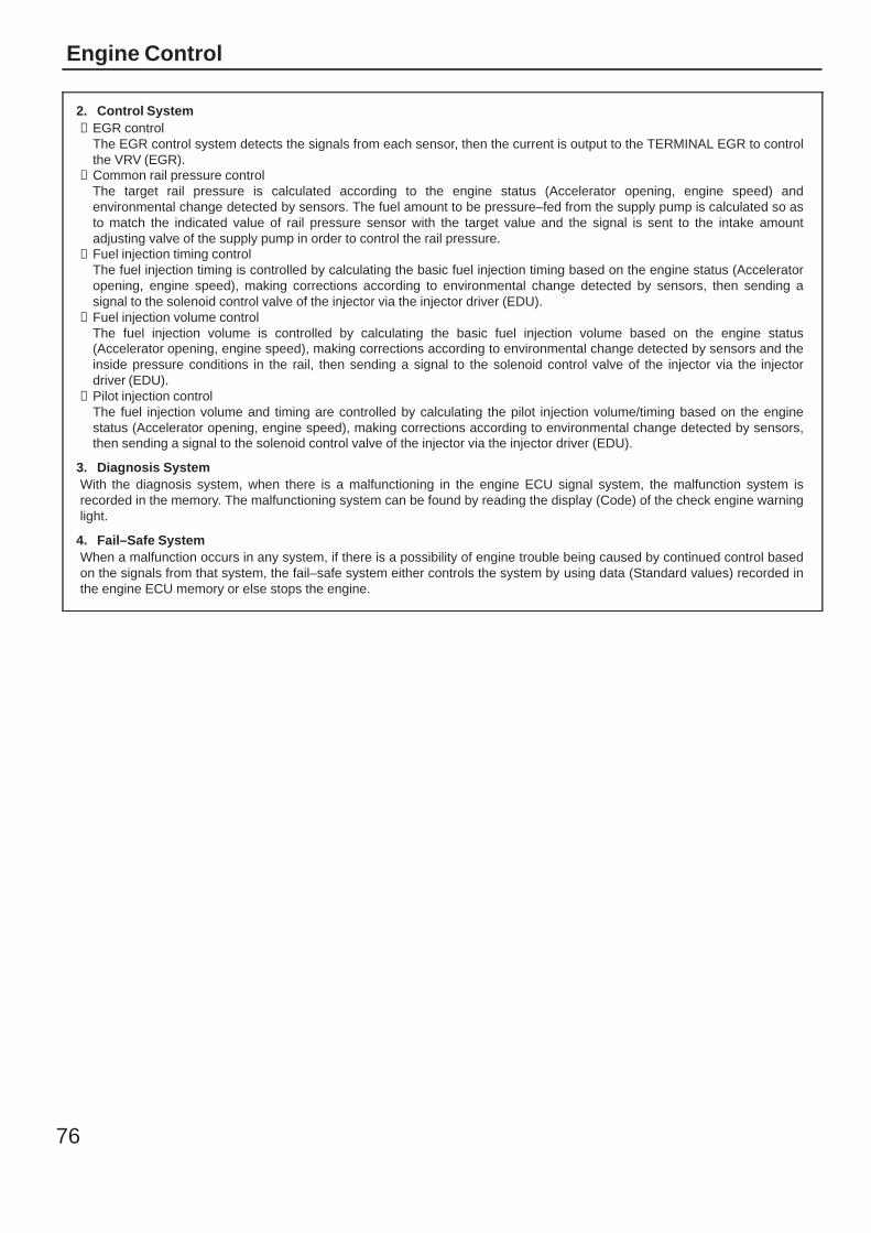
76
Engine Control
2. Control System∗ EGR control
The EGR control system detects the signals from each sensor, then the current is output to the TERMINAL EGR to controlthe VRV (EGR).
∗ Common rail pressure controlThe target rail pressure is calculated according to the engine status (Accelerator opening, engine speed) andenvironmental change detected by sensors. The fuel amount to be pressure–fed from the supply pump is calculated so asto match the indicated value of rail pressure sensor with the target value and the signal is sent to the intake amountadjusting valve of the supply pump in order to control the rail pressure.
∗ Fuel injection timing controlThe fuel injection timing is controlled by calculating the basic fuel injection timing based on the engine status (Acceleratoropening, engine speed), making corrections according to environmental change detected by sensors, then sending asignal to the solenoid control valve of the injector via the injector driver (EDU).
∗ Fuel injection volume controlThe fuel injection volume is controlled by calculating the basic fuel injection volume based on the engine status(Accelerator opening, engine speed), making corrections according to environmental change detected by sensors and theinside pressure conditions in the rail, then sending a signal to the solenoid control valve of the injector via the injectordriver (EDU).
∗ Pilot injection controlThe fuel injection volume and timing are controlled by calculating the pilot injection volume/timing based on the enginestatus (Accelerator opening, engine speed), making corrections according to environmental change detected by sensors,then sending a signal to the solenoid control valve of the injector via the injector driver (EDU).
3. Diagnosis SystemWith the diagnosis system, when there is a malfunctioning in the engine ECU signal system, the malfunction system isrecorded in the memory. The malfunctioning system can be found by reading the display (Code) of the check engine warninglight.
4. Fail–Safe SystemWhen a malfunction occurs in any system, if there is a possibility of engine trouble being caused by continued control basedon the signals from that system, the fail–safe system either controls the system by using data (Standard values) recorded inthe engine ECU memory or else stops the engine.
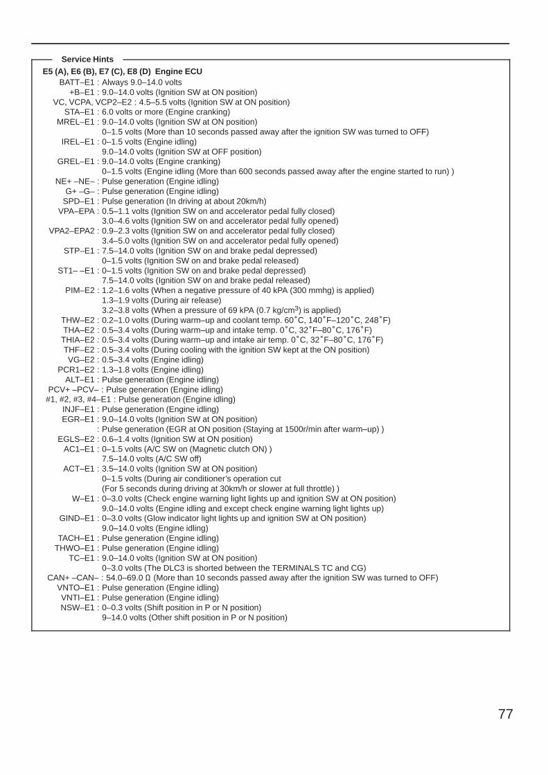
77
E5 (A), E6 (B), E7 (C), E8 (D) Engine ECUBATT–E1 : Always 9.0–14.0 volts
+B–E1 : 9.0–14.0 volts (Ignition SW at ON position)VC, VCPA, VCP2–E2 : 4.5–5.5 volts (Ignition SW at ON position)
STA–E1 : 6.0 volts or more (Engine cranking)MREL–E1 : 9.0–14.0 volts (Ignition SW at ON position)
0–1.5 volts (More than 10 seconds passed away after the ignition SW was turned to OFF)IREL–E1 : 0–1.5 volts (Engine idling)
9.0–14.0 volts (Ignition SW at OFF position)GREL–E1 : 9.0–14.0 volts (Engine cranking)
0–1.5 volts (Engine idling (More than 600 seconds passed away after the engine started to run) )NE+ –NE– : Pulse generation (Engine idling)
G+ –G– : Pulse generation (Engine idling)SPD–E1 : Pulse generation (In driving at about 20km/h)
VPA–EPA : 0.5–1.1 volts (Ignition SW on and accelerator pedal fully closed)3.0–4.6 volts (Ignition SW on and accelerator pedal fully opened)
VPA2–EPA2 : 0.9–2.3 volts (Ignition SW on and accelerator pedal fully closed)3.4–5.0 volts (Ignition SW on and accelerator pedal fully opened)
STP–E1 : 7.5–14.0 volts (Ignition SW on and brake pedal depressed)0–1.5 volts (Ignition SW on and brake pedal released)
ST1– –E1 : 0–1.5 volts (Ignition SW on and brake pedal depressed)7.5–14.0 volts (Ignition SW on and brake pedal released)
PIM–E2 : 1.2–1.6 volts (When a negative pressure of 40 kPA (300 mmhg) is applied)1.3–1.9 volts (During air release)3.2–3.8 volts (When a pressure of 69 kPA (0.7 kg/cm3) is applied)
THW–E2 : 0.2–1.0 volts (During warm–up and coolant temp. 60C, 140F–120C, 248F)THA–E2 : 0.5–3.4 volts (During warm–up and intake temp. 0C, 32F–80C, 176F)THIA–E2 : 0.5–3.4 volts (During warm–up and intake air temp. 0C, 32F–80C, 176F)THF–E2 : 0.5–3.4 volts (During cooling with the ignition SW kept at the ON position)VG–E2 : 0.5–3.4 volts (Engine idling)
PCR1–E2 : 1.3–1.8 volts (Engine idling)ALT–E1 : Pulse generation (Engine idling)
PCV+ –PCV– : Pulse generation (Engine idling)#1, #2, #3, #4–E1 : Pulse generation (Engine idling)
INJF–E1 : Pulse generation (Engine idling)EGR–E1 : 9.0–14.0 volts (Ignition SW at ON position)
: Pulse generation (EGR at ON position (Staying at 1500r/min after warm–up) )EGLS–E2 : 0.6–1.4 volts (Ignition SW at ON position)
AC1–E1 : 0–1.5 volts (A/C SW on (Magnetic clutch ON) )7.5–14.0 volts (A/C SW off)
ACT–E1 : 3.5–14.0 volts (Ignition SW at ON position)0–1.5 volts (During air conditioner’s operation cut(For 5 seconds during driving at 30km/h or slower at full throttle) )
W–E1 : 0–3.0 volts (Check engine warning light lights up and ignition SW at ON position)9.0–14.0 volts (Engine idling and except check engine warning light lights up)
GIND–E1 : 0–3.0 volts (Glow indicator light lights up and ignition SW at ON position)9.0–14.0 volts (Engine idling)
TACH–E1 : Pulse generation (Engine idling)THWO–E1 : Pulse generation (Engine idling)
TC–E1 : 9.0–14.0 volts (Ignition SW at ON position)0–3.0 volts (The DLC3 is shorted between the TERMINALS TC and CG)
CAN+ –CAN– : 54.0–69.0 Ω (More than 10 seconds passed away after the ignition SW was turned to OFF)VNTO–E1 : Pulse generation (Engine idling)VNTI–E1 : Pulse generation (Engine idling)NSW–E1 : 0–0.3 volts (Shift position in P or N position)
9–14.0 volts (Other shift position in P or N position)
Service Hints
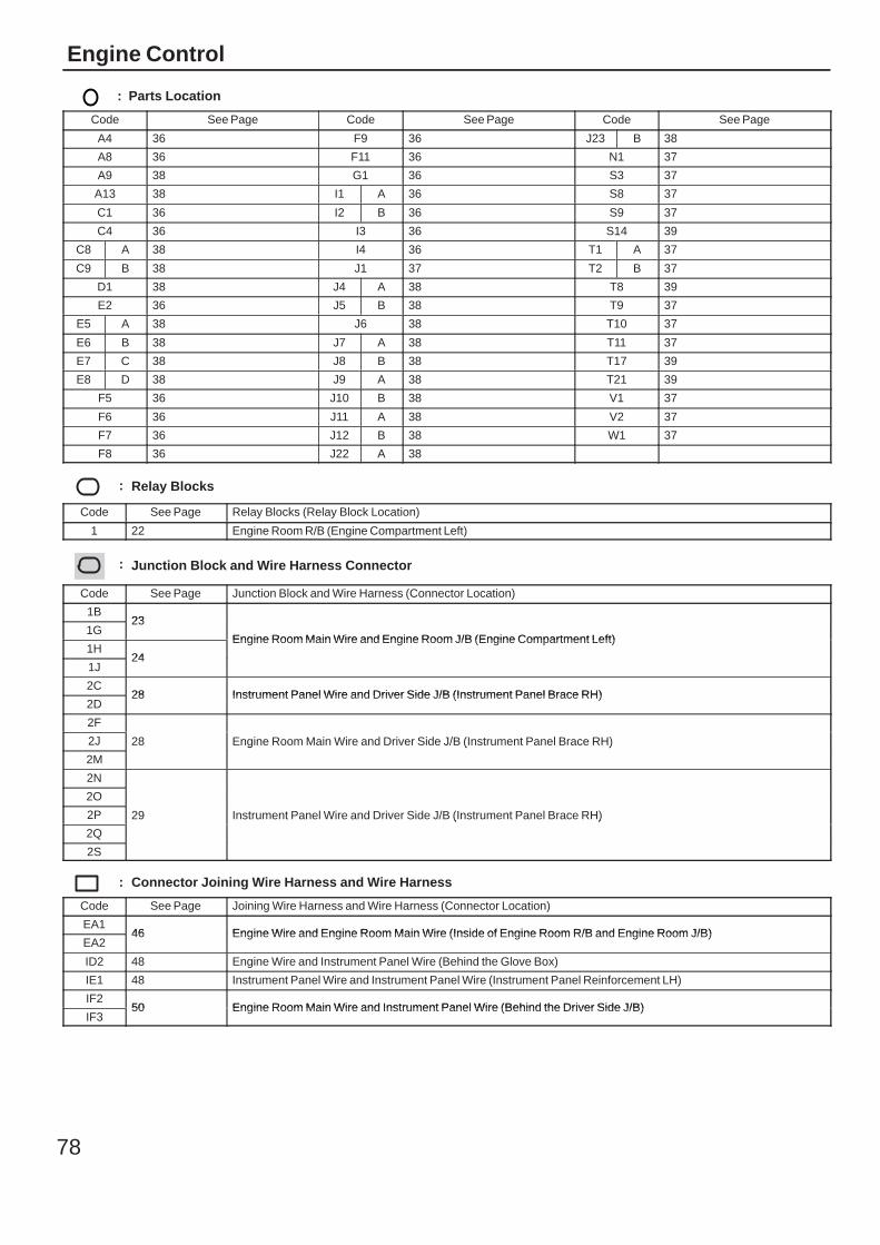
78
Engine Control
: Parts Location
Code See Page Code See Page Code See Page
A4 36 F9 36 J23 B 38
A8 36 F11 36 N1 37
A9 38 G1 36 S3 37
A13 38 I1 A 36 S8 37
C1 36 I2 B 36 S9 37
C4 36 I3 36 S14 39
C8 A 38 I4 36 T1 A 37
C9 B 38 J1 37 T2 B 37
D1 38 J4 A 38 T8 39
E2 36 J5 B 38 T9 37
E5 A 38 J6 38 T10 37
E6 B 38 J7 A 38 T11 37
E7 C 38 J8 B 38 T17 39
E8 D 38 J9 A 38 T21 39
F5 36 J10 B 38 V1 37
F6 36 J11 A 38 V2 37
F7 36 J12 B 38 W1 37
F8 36 J22 A 38
: Relay Blocks
Code See Page Relay Blocks (Relay Block Location)
1 22 Engine Room R/B (Engine Compartment Left)
: Junction Block and Wire Harness Connector
Code See Page Junction Block and Wire Harness (Connector Location)
1B23
Engine Room Main Wire and Engine Room J/B (Engine Compartment Left)1G
23
Engine Room Main Wire and Engine Room J/B (Engine Compartment Left)1H
24
Engine Room Main Wire and Engine Room J/B (Engine Compartment Left)
1J24
2C28 Instrument Panel Wire and Driver Side J/B (Instrument Panel Brace RH)
2D28 Instrument Panel Wire and Driver Side J/B (Instrument Panel Brace RH)
2F
28 Engine Room Main Wire and Driver Side J/B (Instrument Panel Brace RH)2J 28 Engine Room Main Wire and Driver Side J/B (Instrument Panel Brace RH)
2M
28 Engine Room Main Wire and Driver Side J/B (Instrument Panel Brace RH)
2N
29 Instrument Panel Wire and Driver Side J/B (Instrument Panel Brace RH)
2O
29 Instrument Panel Wire and Driver Side J/B (Instrument Panel Brace RH)2P 29 Instrument Panel Wire and Driver Side J/B (Instrument Panel Brace RH)
2Q
29 Instrument Panel Wire and Driver Side J/B (Instrument Panel Brace RH)
2S
: Connector Joining Wire Harness and Wire Harness
Code See Page Joining Wire Harness and Wire Harness (Connector Location)
EA146 Engine Wire and Engine Room Main Wire (Inside of Engine Room R/B and Engine Room J/B)
EA246 Engine Wire and Engine Room Main Wire (Inside of Engine Room R/B and Engine Room J/B)
ID2 48 Engine Wire and Instrument Panel Wire (Behind the Glove Box)
IE1 48 Instrument Panel Wire and Instrument Panel Wire (Instrument Panel Reinforcement LH)
IF250 Engine Room Main Wire and Instrument Panel Wire (Behind the Driver Side J/B)
IF350 Engine Room Main Wire and Instrument Panel Wire (Behind the Driver Side J/B)
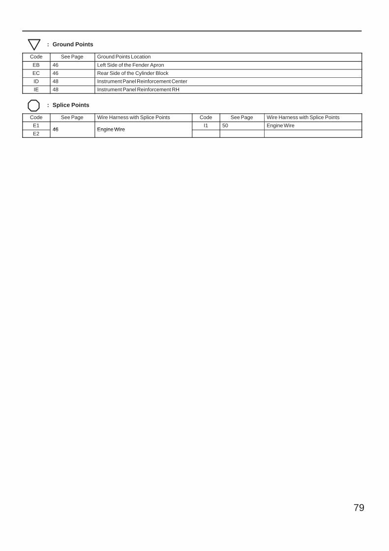
79
: Ground Points
Code See Page Ground Points Location
EB 46 Left Side of the Fender Apron
EC 46 Rear Side of the Cylinder Block
ID 48 Instrument Panel Reinforcement Center
IE 48 Instrument Panel Reinforcement RH
: Splice Points
Code See Page Wire Harness with Splice Points Code See Page Wire Harness with Splice Points
E146 Engine Wire
I1 50 Engine Wire
E246 Engine Wire
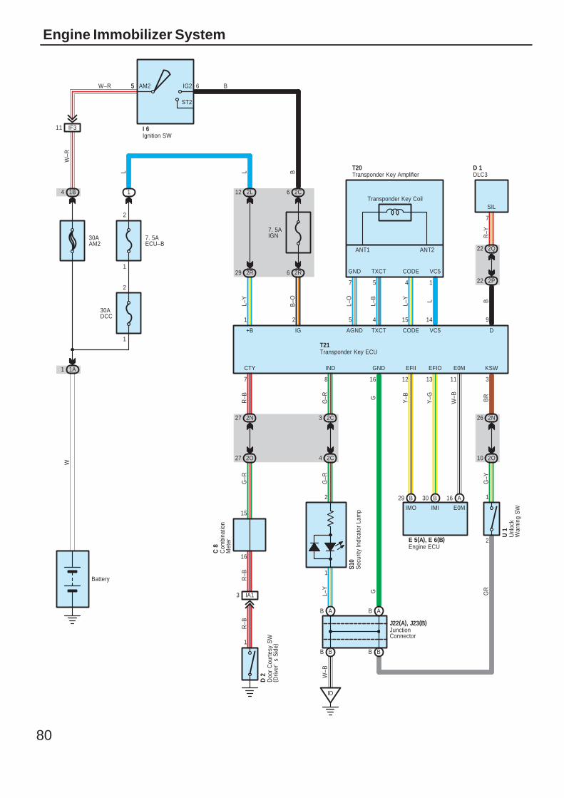
80
Engine Immobilizer System
Battery
7. 5AIGN
5W–R
W
30AAM2
W–R
B
B–O
5 6AM2 IG2
ST2
I 6
1B4
1A1
2R6
2C6
Ignition SWIF311
7. 5AECU–B
1
2
1
2
1 2L12
2R29
2C3
2C4
BB
AB AB
ID
2N26
2O10
B29 B30 A16
27 2O
27 2N
30ADCC
IA13
1
7
1457
16
1
2
31113121687
914154521
2 1
CTY IND GND EFII EFIO E0M KSW
GND TXCT CODE VC5
SIL
W–B
GR
G–Y
BR
W–B
Y–GY–BG
G–R
R–B
G–R
R–B
R–B
L L B
L–O
L–B
L–Y L BL–Y
L–Y G
ANT2ANT1
E0MIMIIMO
DVC5CODETXCTAGNDIG+B
Transponder Key AmplifierT20 D 1
Transponder Key ECUT21
Engine ECUE 5(A), E 6(B)
JunctionConnector
J22(A), J23(B)
Unl
ock
War
ning
SW
U 1
S10
Com
bina
tion
Met
er
C 8
Doo
r C
ourte
sy S
W( D
river
's
Sid
e)
D 2
Transponder Key Coil
2Q22
2P22
R–Y
15
G–R
DLC3
Sec
urity
Indi
cato
r La
mp
BB
81
T21 Transponder Key ECU1–Ground : Always approx. 12 volts
16–Ground : Always continuity2–Ground : Approx. 12 volts with the ignition SW at ON position
: Parts Location
Code See Page Code See Page Code See Page
C8 38 E5 A 38 S10 39
D1 38 E6 B 38 T20 39
D2
40 (Double Cab) I6 38 T21 39
D2 42 (Extra Cab) J22 A 38 U1 39D2
44 (Single Cab) J23 B 38
: Relay Blocks
Code See Page Relay Blocks (Relay Block Location)
1 22 Engine Room R/B (Engine Compartment Left)
: Junction Block and Wire Harness Connector
Code See Page Junction Block and Wire Harness (Connector Location)
1A23 Engine Room Main Wire and Engine Room J/B (Engine Compartment Left)
1B23 Engine Room Main Wire and Engine Room J/B (Engine Compartment Left)
2C 28 Instrument Panel Wire and Driver Side J/B (Instrument Panel Brace RH)
2L 28 Engine Room Main Wire and Driver Side J/B (Instrument Panel Brace RH)
2N
29 Instrument Panel Wire and Driver Side J/B (Instrument Panel Brace RH)
2O
29 Instrument Panel Wire and Driver Side J/B (Instrument Panel Brace RH)2P 29 Instrument Panel Wire and Driver Side J/B (Instrument Panel Brace RH)
2Q
29 Instrument Panel Wire and Driver Side J/B (Instrument Panel Brace RH)
2R
: Connector Joining Wire Harness and Wire Harness
Code See Page Joining Wire Harness and Wire Harness (Connector Location)
IA1 48 Instrument Panel Wire and Floor Wire (Left Kick Panel)
IF3 50 Engine Room Main Wire and Instrument Panel Wire (Behind the Driver Side J/B)
: Ground Points
Code See Page Ground Points Location
ID 48 Instrument Panel Reinforcement Center
Service Hints
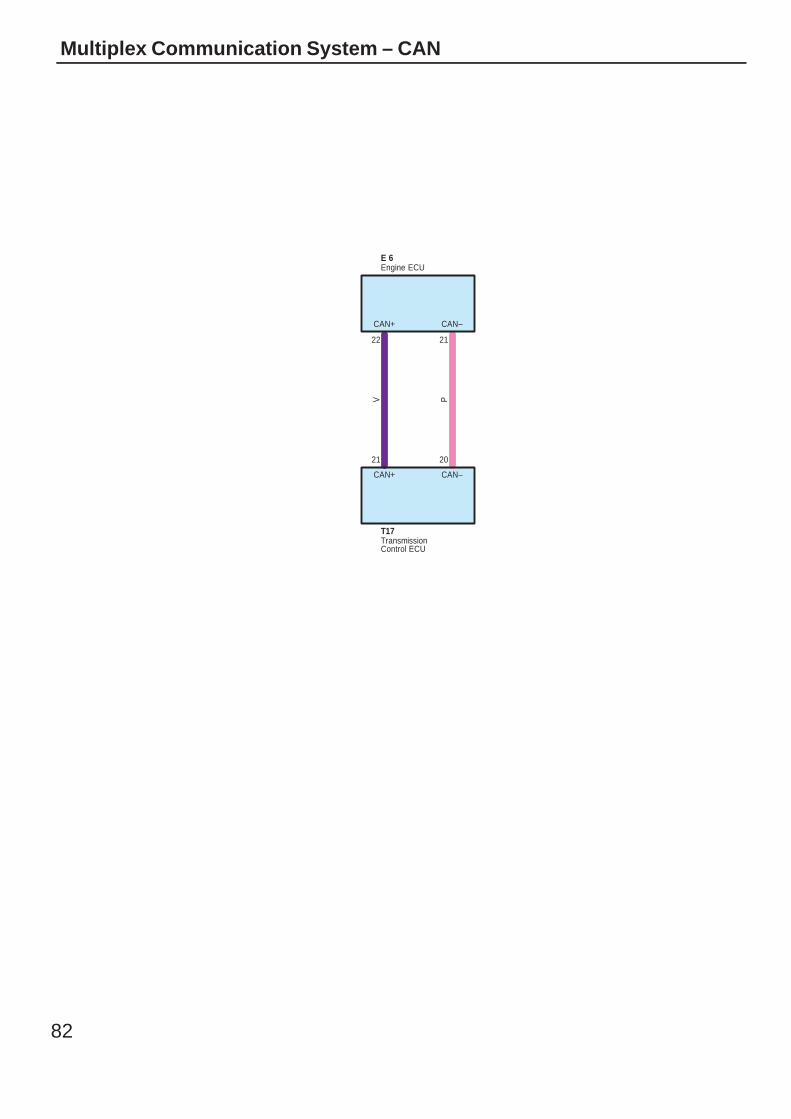
82
Multiplex Communication System – CAN
22
21
V
CAN+
CAN+
21
20
P
CAN–
CAN–
T17
E 6Engine ECU
TransmissionControl ECU
83
Multiplex communication system (CAN) uses a serial communication protocol and communicates with a differential voltage.In this network system, TERMINALS CAN+ and CAN– are used for communication between the ECUs and sensors, andexcellent data communication speed and communication error detecting facility are provided. This system is working for thefollowing systems:∗ Engine Control∗ ECT
: Parts Location
Code See Page Code See Page Code See Page
E6 38 T17 39
System Outline
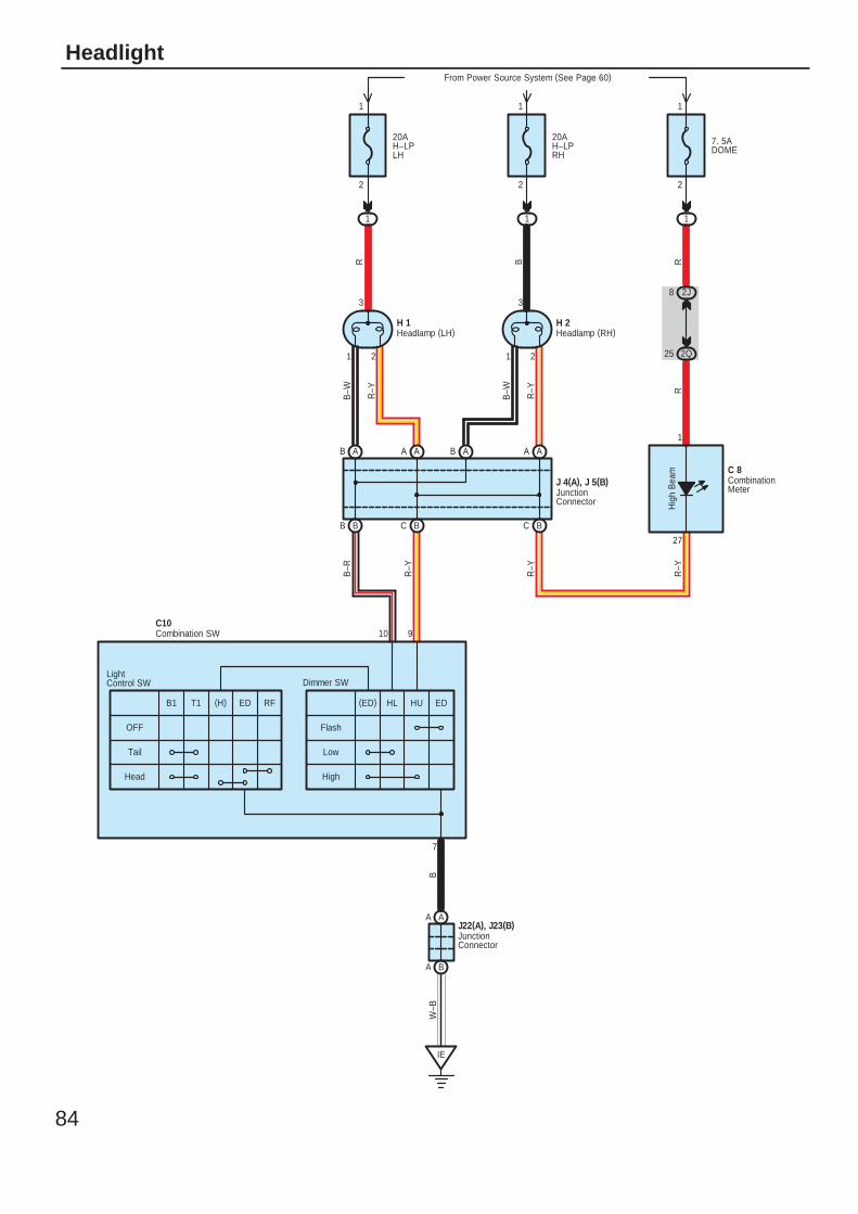
84
Headlight
1 2
3
1 2
3
BB BC
AB AAAA AB
BC
AA
BA
IE
Hig
h B
eam
7. 5ADOME
1
2Q25
2J8
20AH–LPLH
From Power Source System (See Page 60)
1 1
20AH–LPRH
Flash
Low
High
OFF
Tail
Head
7
10 9
R B R
B–W R–Y
B–W
B–R
R–Y
R–Y
R–Y
RR–Y
BW
–B1
27
C 8
2
1
H 2H 1
J 4(A), J 5(B)
LightControl SW Dimmer SW
2
1
2
1
B1 T1 (H) ED RF (ED) HL HU ED
CombinationMeter
Headlamp (LH) Headlamp (RH)
JunctionConnector
JunctionConnector
J22(A), J23(B)
Combination SWC10

85
C10 Combination SW10–7 : Continuity with the dimmer SW at LOW position and the light control SW at HEAD position
9–7 : Continuity with the dimmer SW at FLASH position or the dimmer SW at HIGH position andthe light control SW at HEAD position
: Parts Location
Code See Page Code See Page Code See Page
C8 38 H2 36 J22 A 38
C10 38 J4 A 38 J23 B 38
H1 36 J5 B 38
: Relay Blocks
Code See Page Relay Blocks (Relay Block Location)
1 22 Engine Room R/B (Engine Compartment Left)
: Junction Block and Wire Harness Connector
Code See Page Junction Block and Wire Harness (Connector Location)
2J 28 Engine Room Main Wire and Driver Side J/B (Instrument Panel Brace RH)
2Q 29 Instrument Panel Wire and Driver Side J/B (Instrument Panel Brace RH)
: Ground Points
Code See Page Ground Points Location
IE 48 Instrument Panel Reinforcement RH
Service Hints
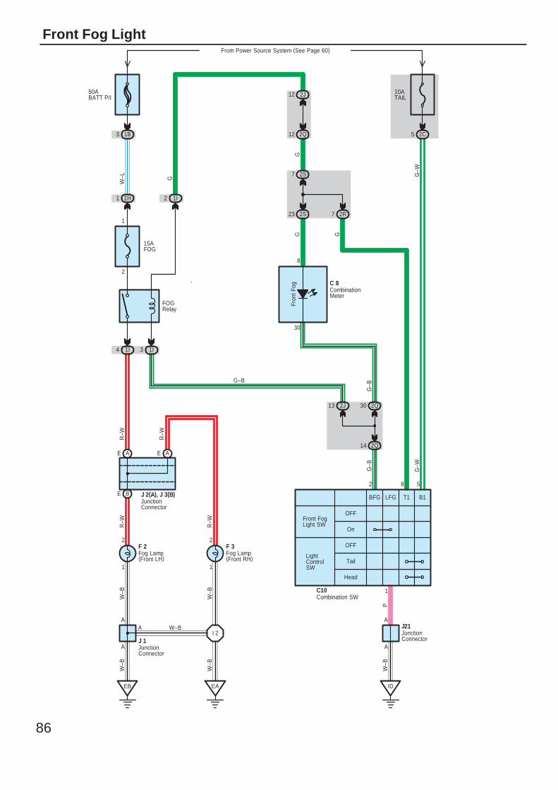
86
Front Fog Light
R–W
R–W
1
2
1
2
On
OFFFront FogLight SW
A
FOGRelay
R–W
PW
–B
J21
C10
2
A
1
R–W
G
G–B
1
2
W–L
15AFOG
G–B
G
LightControlSW
G
G–W
W–B
W–B
A
A
W–B
W–B
W–BA
From Power Source System (See Page 60)
2C3
10ATAIL
51B
EB EA ID
1H1 1I2
1I31I4
AEAE
BE J 2(A), J 3(B)
J 1
2J13
2Q14
2Q30
2J12
2S7
2Q12
2S23 2R7
Fron
t Fog
8
30
OFF
Tail
Head
58
G–B
G
50ABATT P/I
I 2
C 8
F 3F 2
BFG LFG B1T1
G–W
CombinationMeter
Fog Lamp(Front LH)
Fog Lamp(Front RH)
Combination SW
JunctionConnector
JunctionConnector
JunctionConnector
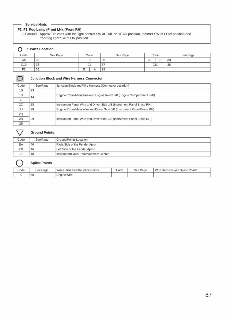
87
F2, F3 Fog Lamp (Front LH), (Front RH)2–Ground : Approx. 12 volts with the light control SW at TAIL or HEAD position, dimmer SW at LOW position and
front fog light SW at ON position
: Parts Location
Code See Page Code See Page Code See Page
C8 38 F3 36 J3 B 38
C10 38 J1 37 J21 38
F2 36 J2 A 38
: Junction Block and Wire Harness Connector
Code See Page Junction Block and Wire Harness (Connector Location)
1B 23
Engine Room Main Wire and Engine Room J/B (Engine Compartment Left)1H24
Engine Room Main Wire and Engine Room J/B (Engine Compartment Left)
1I24
Engine Room Main Wire and Engine Room J/B (Engine Compartment Left)
2C 28 Instrument Panel Wire and Driver Side J/B (Instrument Panel Brace RH)
2J 28 Engine Room Main Wire and Driver Side J/B (Instrument Panel Brace RH)
2Q
29 Instrument Panel Wire and Driver Side J/B (Instrument Panel Brace RH)2R 29 Instrument Panel Wire and Driver Side J/B (Instrument Panel Brace RH)
2S
29 Instrument Panel Wire and Driver Side J/B (Instrument Panel Brace RH)
: Ground Points
Code See Page Ground Points Location
EA 46 Right Side of the Fender Apron
EB 46 Left Side of the Fender Apron
ID 48 Instrument Panel Reinforcement Center
: Splice Points
Code See Page Wire Harness with Splice Points Code See Page Wire Harness with Splice Points
I2 50 Engine Wire
Service Hints
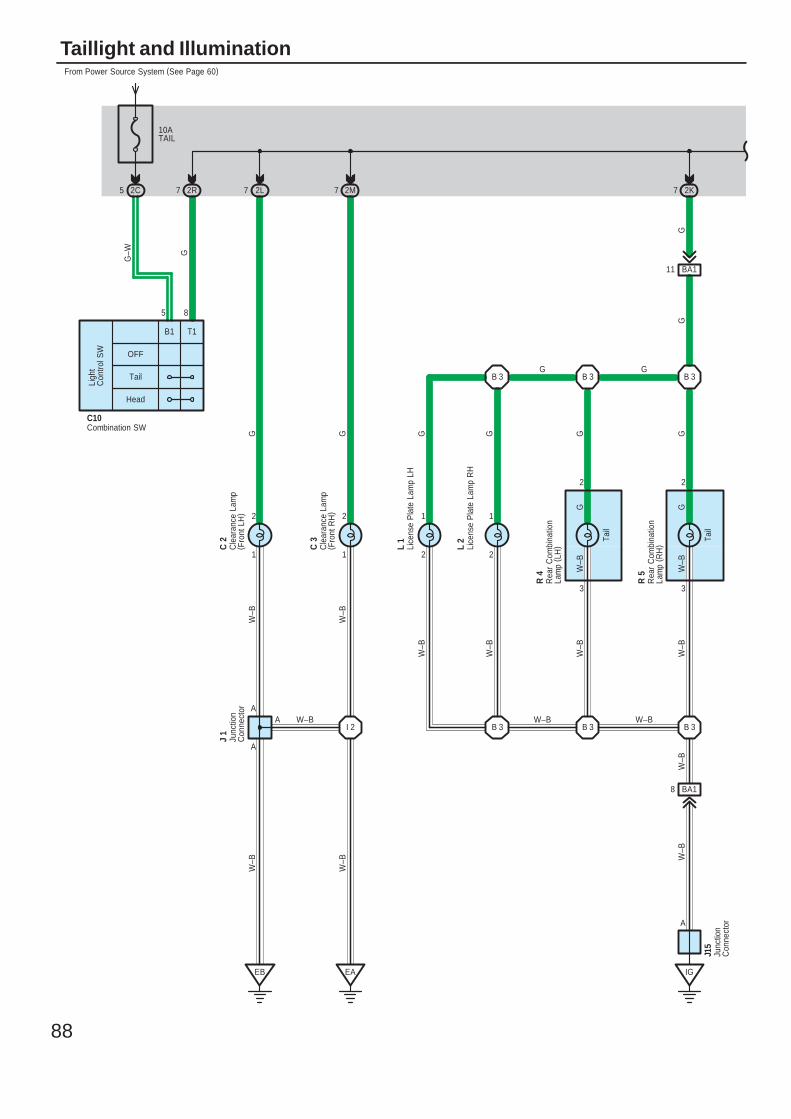
88
Taillight and Illumination
10ATAIL
From Power Source System (See Page 60)
2C5 2R7
1
2
1
2
2
1
2L7 2M7
EB EA
A
A
I 2
3
2
Tail
3
2
Tail
2K7
IG
A W–B
GGG
W–B
W–B
GGG
G
G–W
W–B
W–B
W–B
W–B
W–B
C 2
C 3
L 2
J 1
R 4
R 5
8
OFF
B1 T1
Tail
Head
Ligh
tC
ontro
l SW
5
GGW
–B
W–B
C10
Cle
aran
ce L
amp
( Fro
nt L
H)
Cle
aran
ce L
amp
( Fro
nt R
H)
Combination SW
Junc
tion
Con
nect
or
Rea
r C
ombi
natio
nLa
mp
( LH
)
Rea
r C
ombi
natio
nLa
mp
( RH
)
B 3B 3B 3
B 3B 3B 3
2
1
W–B
G
L 1
BA111
G
W–B W–B
GG
BA18
A
Junc
tion
Con
nect
or
J15
W–B
W–B
Lice
nse
Pla
te L
amp
RH
Lice
nse
Pla
te L
amp
LH
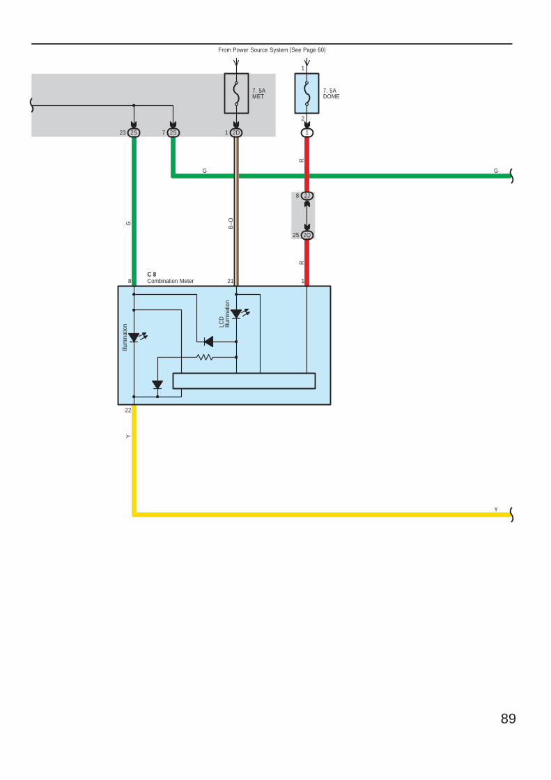
89
2S23
7. 5AMET
From Power Source System (See Page 60)
2D12S7
22
218
Y
G
B–OG
Y
G
Illum
inat
ion LC
DIll
umin
atio
n
1
R
2J8
2Q25
7. 5ADOME
1
1
2
Combination MeterC 8
R
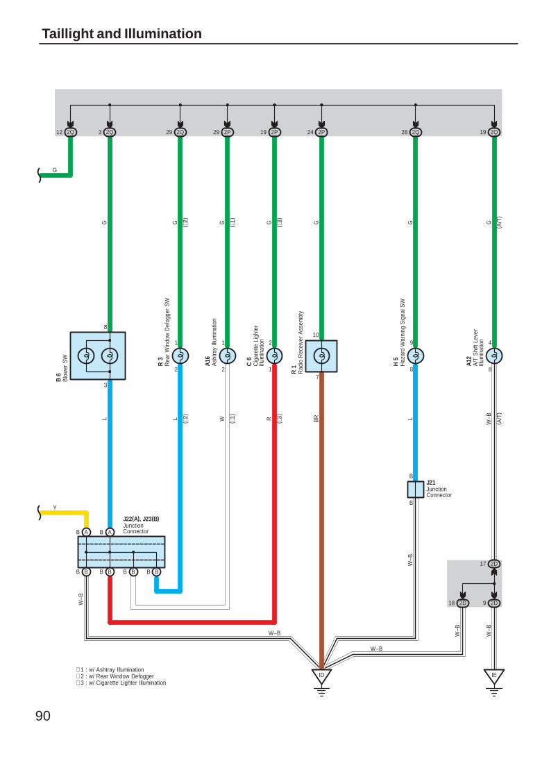
90
Taillight and Illumination
109
8
24 2P
W–B
L L RW W–BLBR
2Q28
G GG G G G G
ID
BB
B 6
BB
W–B
BB BB
AB AB
3
8
BJ21
2
1
2
1
1
2
2Q3 2Q29 2P29
W–B
2P19 2Q19
8
4
IE
2D92D18
2D17
BY
W–B
W–B
W–B
R 3
A16
C 6
A12
H 5
R 1
( ∗2)
( ∗1)
( ∗3)
( A/T
)
( ∗2)
( ∗3)
( ∗1)
( A/T
)
∗ 1 : w/ Ashtray Illumination∗ 2 : w/ Rear Window Defogger∗ 3 : w/ Cigarette Lighter Illumination
7
2Q12
G
Ash
tray
Illum
inat
ion
Cig
aret
te L
ight
erIll
umin
atio
n
Haz
ard
War
ning
Sig
nal S
W
JunctionConnector
Rad
io R
ecei
ver
Ass
embl
y
Rea
r W
indo
w D
efog
ger
SW
JunctionConnector
J22(A), J23(B)
A/T
Shi
ft Le
ver
Illum
inat
ion
Blo
wer
SW
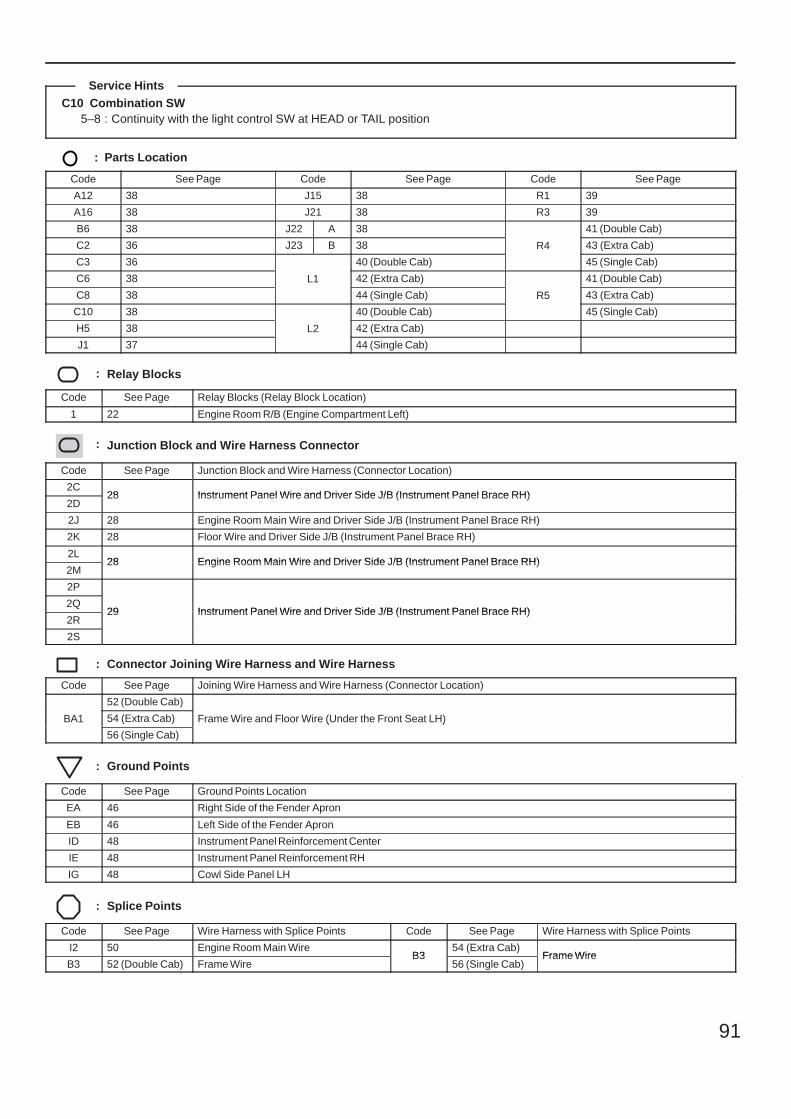
91
C10 Combination SW5–8 : Continuity with the light control SW at HEAD or TAIL position
: Parts Location
Code See Page Code See Page Code See Page
A12 38 J15 38 R1 39
A16 38 J21 38 R3 39
B6 38 J22 A 38
R4
41 (Double Cab)
C2 36 J23 B 38 R4 43 (Extra Cab)
C3 36
L1
40 (Double Cab)
R4
45 (Single Cab)
C6 38 L1 42 (Extra Cab)
R5
41 (Double Cab)
C8 38
L1
44 (Single Cab) R5 43 (Extra Cab)
C10 38
L2
40 (Double Cab)
R5
45 (Single Cab)
H5 38 L2 42 (Extra Cab)
J1 37
L2
44 (Single Cab)
: Relay Blocks
Code See Page Relay Blocks (Relay Block Location)
1 22 Engine Room R/B (Engine Compartment Left)
: Junction Block and Wire Harness Connector
Code See Page Junction Block and Wire Harness (Connector Location)
2C28 Instrument Panel Wire and Driver Side J/B (Instrument Panel Brace RH)
2D28 Instrument Panel Wire and Driver Side J/B (Instrument Panel Brace RH)
2J 28 Engine Room Main Wire and Driver Side J/B (Instrument Panel Brace RH)
2K 28 Floor Wire and Driver Side J/B (Instrument Panel Brace RH)
2L28 Engine Room Main Wire and Driver Side J/B (Instrument Panel Brace RH)
2M28 Engine Room Main Wire and Driver Side J/B (Instrument Panel Brace RH)
2P
29 Instrument Panel Wire and Driver Side J/B (Instrument Panel Brace RH)2Q
29 Instrument Panel Wire and Driver Side J/B (Instrument Panel Brace RH)2R
29 Instrument Panel Wire and Driver Side J/B (Instrument Panel Brace RH)
2S
: Connector Joining Wire Harness and Wire Harness
Code See Page Joining Wire Harness and Wire Harness (Connector Location)
BA1
52 (Double Cab)
Frame Wire and Floor Wire (Under the Front Seat LH)BA1 54 (Extra Cab) Frame Wire and Floor Wire (Under the Front Seat LH)BA1
56 (Single Cab)
Frame Wire and Floor Wire (Under the Front Seat LH)
: Ground Points
Code See Page Ground Points Location
EA 46 Right Side of the Fender Apron
EB 46 Left Side of the Fender Apron
ID 48 Instrument Panel Reinforcement Center
IE 48 Instrument Panel Reinforcement RH
IG 48 Cowl Side Panel LH
: Splice Points
Code See Page Wire Harness with Splice Points Code See Page Wire Harness with Splice Points
I2 50 Engine Room Main WireB3
54 (Extra Cab)Frame Wire
B3 52 (Double Cab) Frame WireB3
56 (Single Cab)Frame Wire
Service Hints
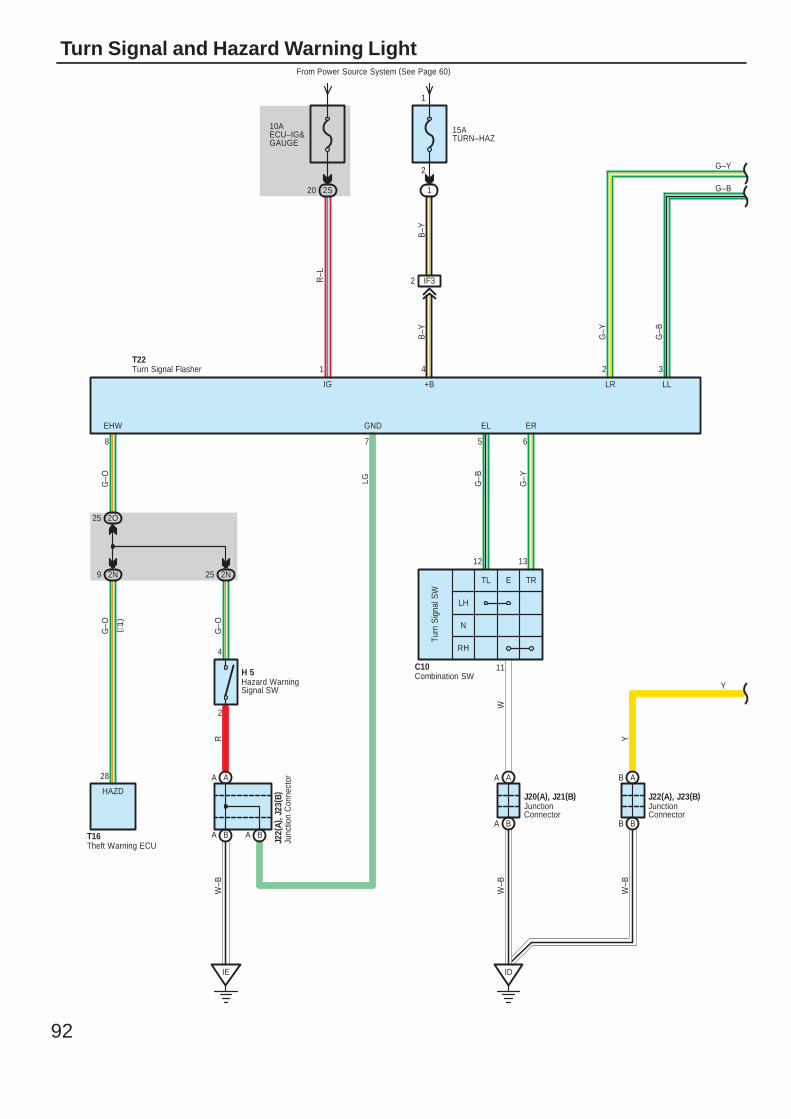
92
Turn Signal and Hazard Warning Light
ABAAAA
BA BABA BB
2N9 2N25
2O25
IE ID
11
6578
2
4
12 13
G–O LG G–B
G–Y
W
YRG
–O
G–O
W–B
W–B
W–B
LH
N
RH
Turn
Sig
nal S
W
C10
( ∗1)
28
HAZD
10AECU–IG&GAUGE
From Power Source System (See Page 60)
2S20
15ATURN–HAZ
IF32
1
1 2
B–Y
G–Y
R–L
1
2
LRIG
ERELGNDEHW
T22
Y
G–B
G–Y
TL E TR
H 5
T16 J22(
A), J
23( B
) J20(A), J21(B) J22(A), J23(B)
Hazard WarningSignal SW
Combination SW
JunctionConnector
Junc
tion
Con
nect
or
JunctionConnector
Turn Signal Flasher 3
G–B
LL+B
B–Y
4
Theft Warning ECU
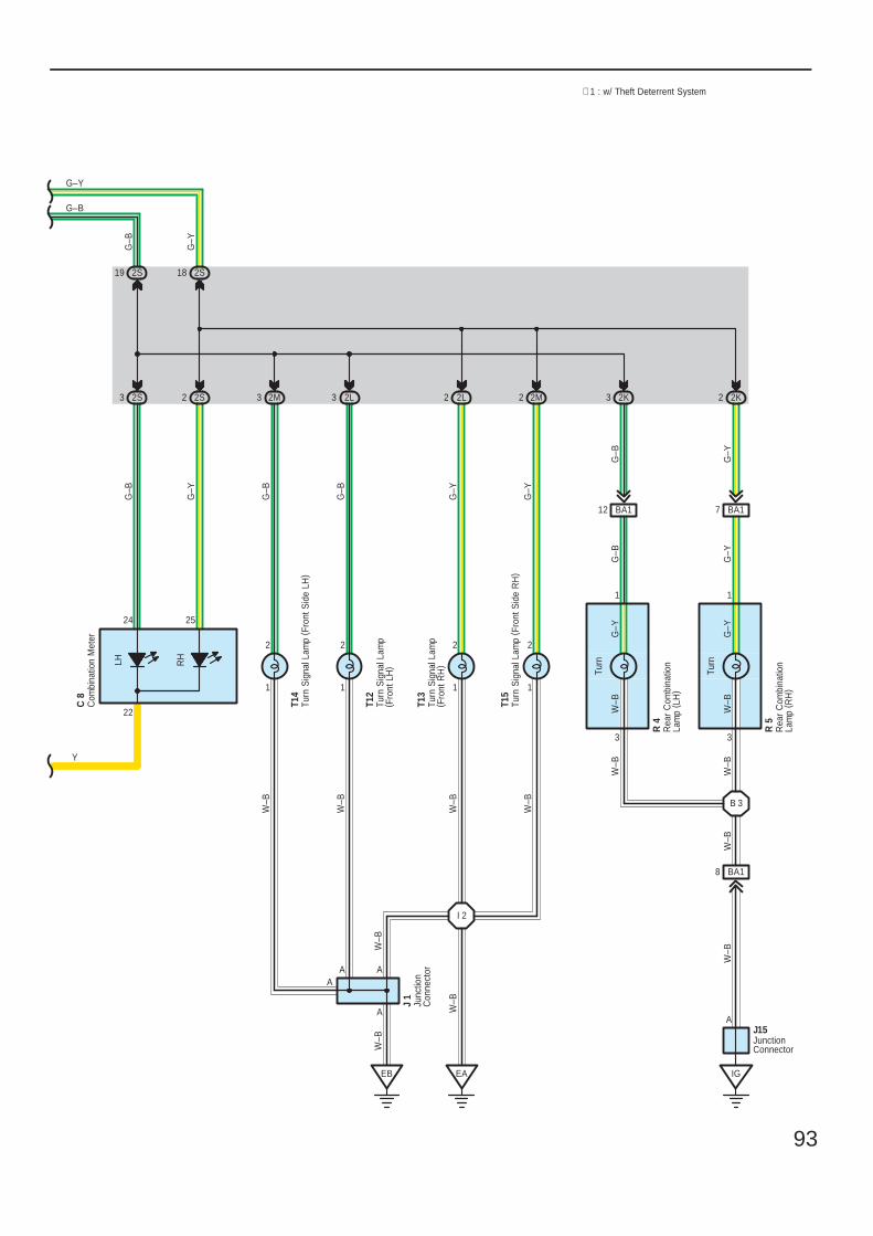
93
2L32S3 2S2 2L2 2K3 2K2
EAEB
I 2
11
2
2524
2
A
33
1
22
A
A
1
W–B
W–B
W–B
W–B
W–B
W–B
G–Y
G–B
G–Y
G–Y
G–B
G–B
G–Y
W–B
W–B
G–Y
R 5
R 4
T12
Y
∗ 1 : w/ Theft Deterrent System
LH RH
Turn
Turn
G–Y
G–B
Rea
r C
ombi
natio
nLa
mp
( LH
)
Rea
r C
ombi
natio
nLa
mp
( RH
)
Turn
Sig
nal L
amp
( Fro
nt L
H)
2S182S19
G–B
G–Y
Junc
tion
Con
nect
or
J 1
W–B
A
W–B
2
1
2M3
G–B
T14
Com
bina
tion
Met
erC
8
Turn
Sig
nal L
amp
( Fro
nt R
H)
T13
G–Y
W–B
1
2
2M2
T15
B 3
IG
JunctionConnector
J15A
BA18
W–B
W–B
BA112 BA17
G–Y
G–B
Turn
Sig
nal L
amp
( Fro
nt S
ide
LH)
Turn
Sig
nal L
amp
( Fro
nt S
ide
RH
)
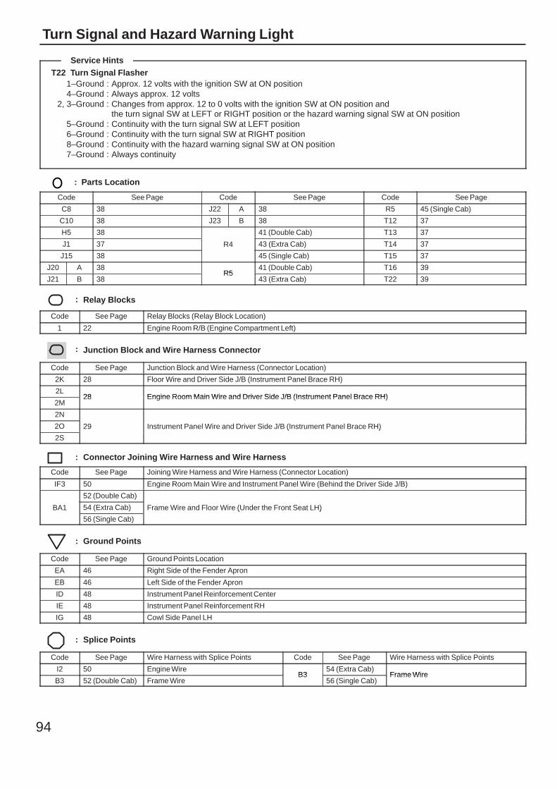
94
Turn Signal and Hazard Warning Light
T22 Turn Signal Flasher1–Ground : Approx. 12 volts with the ignition SW at ON position4–Ground : Always approx. 12 volts
2, 3–Ground : Changes from approx. 12 to 0 volts with the ignition SW at ON position andthe turn signal SW at LEFT or RIGHT position or the hazard warning signal SW at ON position
5–Ground : Continuity with the turn signal SW at LEFT position6–Ground : Continuity with the turn signal SW at RIGHT position8–Ground : Continuity with the hazard warning signal SW at ON position7–Ground : Always continuity
: Parts Location
Code See Page Code See Page Code See Page
C8 38 J22 A 38 R5 45 (Single Cab)
C10 38 J23 B 38 T12 37
H5 38
R4
41 (Double Cab) T13 37
J1 37 R4 43 (Extra Cab) T14 37
J15 38
R4
45 (Single Cab) T15 37
J20 A 38R5
41 (Double Cab) T16 39
J21 B 38R5
43 (Extra Cab) T22 39
: Relay Blocks
Code See Page Relay Blocks (Relay Block Location)
1 22 Engine Room R/B (Engine Compartment Left)
: Junction Block and Wire Harness Connector
Code See Page Junction Block and Wire Harness (Connector Location)
2K 28 Floor Wire and Driver Side J/B (Instrument Panel Brace RH)
2L28 Engine Room Main Wire and Driver Side J/B (Instrument Panel Brace RH)
2M28 Engine Room Main Wire and Driver Side J/B (Instrument Panel Brace RH)
2N
29 Instrument Panel Wire and Driver Side J/B (Instrument Panel Brace RH)2O 29 Instrument Panel Wire and Driver Side J/B (Instrument Panel Brace RH)
2S
29 Instrument Panel Wire and Driver Side J/B (Instrument Panel Brace RH)
: Connector Joining Wire Harness and Wire Harness
Code See Page Joining Wire Harness and Wire Harness (Connector Location)
IF3 50 Engine Room Main Wire and Instrument Panel Wire (Behind the Driver Side J/B)
BA1
52 (Double Cab)
Frame Wire and Floor Wire (Under the Front Seat LH)BA1 54 (Extra Cab) Frame Wire and Floor Wire (Under the Front Seat LH)BA1
56 (Single Cab)
Frame Wire and Floor Wire (Under the Front Seat LH)
: Ground Points
Code See Page Ground Points Location
EA 46 Right Side of the Fender Apron
EB 46 Left Side of the Fender Apron
ID 48 Instrument Panel Reinforcement Center
IE 48 Instrument Panel Reinforcement RH
IG 48 Cowl Side Panel LH
: Splice Points
Code See Page Wire Harness with Splice Points Code See Page Wire Harness with Splice Points
I2 50 Engine WireB3
54 (Extra Cab)Frame Wire
B3 52 (Double Cab) Frame WireB3
56 (Single Cab)Frame Wire
Service Hints

95
Memo
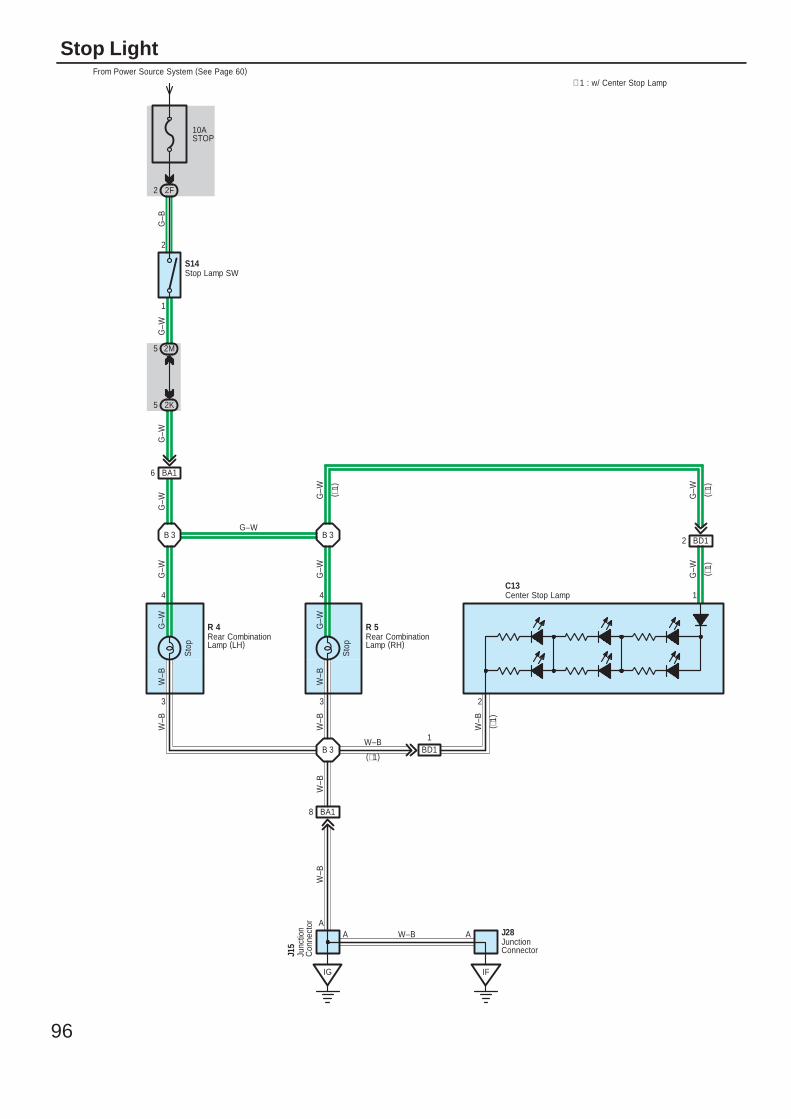
96
Stop Light
10ASTOP
From Power Source System (See Page 60)
2F2
2M5
2K5
3 3
4 4
Sto
p
Sto
p
W–B
G–W
G–W
W–B
G–W
G–W
G–W
G–W
G–B
S14
BD12
G–W
G–W
( ∗1)
( ∗1)
1
2
∗ 1 : w/ Center Stop Lamp
R 4 R 5Rear CombinationLamp (LH)
Rear CombinationLamp (RH)
Stop Lamp SW
W–B
W–B
IF
JunctionConnector
J28A
B 3
IG
A
BA18
W–B
W–B
W–B
Junc
tion
Con
nect
or
J15
A
BA16
G–W
B 3 B 3
G–W ( ∗1)
1
2
Center Stop LampC13
W–B
( ∗1)
G–W
BD11W–B
(∗1)
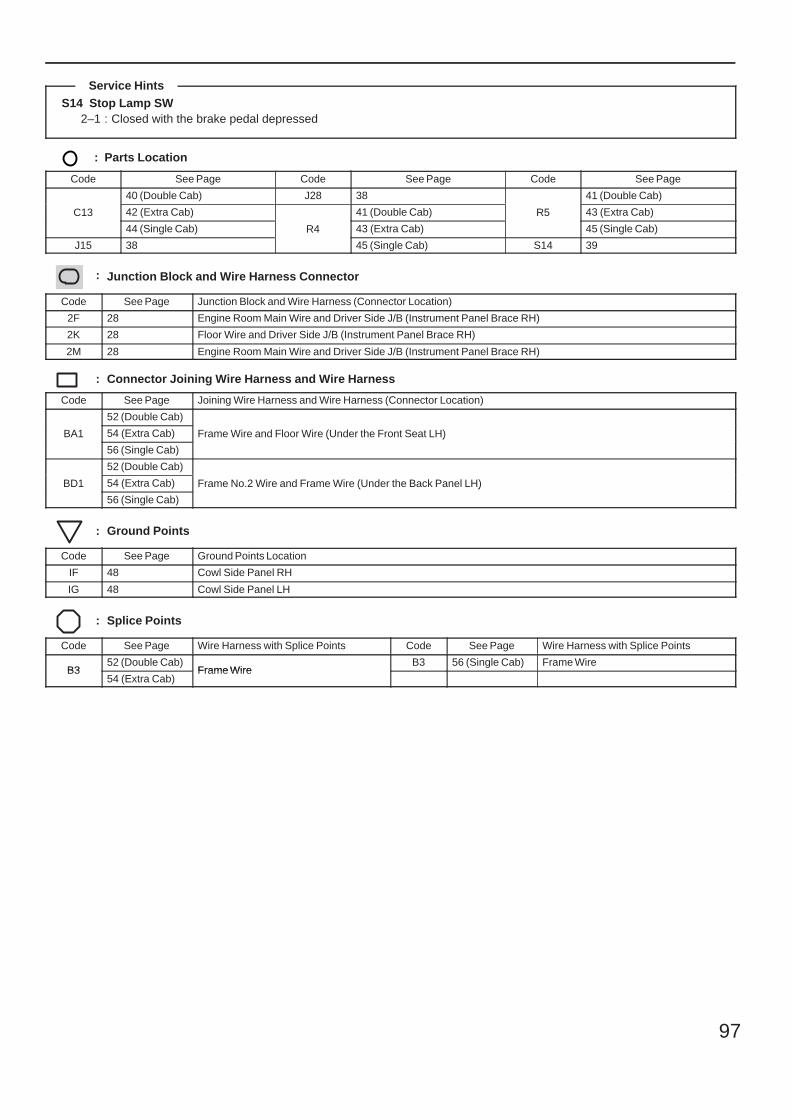
97
S14 Stop Lamp SW2–1 : Closed with the brake pedal depressed
: Parts Location
Code See Page Code See Page Code See Page
C13
40 (Double Cab) J28 38
R5
41 (Double Cab)
C13 42 (Extra Cab)
R4
41 (Double Cab) R5 43 (Extra Cab)C13
44 (Single Cab) R4 43 (Extra Cab)
R5
45 (Single Cab)
J15 38
R4
45 (Single Cab) S14 39
: Junction Block and Wire Harness Connector
Code See Page Junction Block and Wire Harness (Connector Location)
2F 28 Engine Room Main Wire and Driver Side J/B (Instrument Panel Brace RH)
2K 28 Floor Wire and Driver Side J/B (Instrument Panel Brace RH)
2M 28 Engine Room Main Wire and Driver Side J/B (Instrument Panel Brace RH)
: Connector Joining Wire Harness and Wire Harness
Code See Page Joining Wire Harness and Wire Harness (Connector Location)
BA1
52 (Double Cab)
Frame Wire and Floor Wire (Under the Front Seat LH)BA1 54 (Extra Cab) Frame Wire and Floor Wire (Under the Front Seat LH)BA1
56 (Single Cab)
Frame Wire and Floor Wire (Under the Front Seat LH)
BD1
52 (Double Cab)
Frame No.2 Wire and Frame Wire (Under the Back Panel LH)BD1 54 (Extra Cab) Frame No.2 Wire and Frame Wire (Under the Back Panel LH)BD1
56 (Single Cab)
Frame No.2 Wire and Frame Wire (Under the Back Panel LH)
: Ground Points
Code See Page Ground Points Location
IF 48 Cowl Side Panel RH
IG 48 Cowl Side Panel LH
: Splice Points
Code See Page Wire Harness with Splice Points Code See Page Wire Harness with Splice Points
B352 (Double Cab)
Frame WireB3 56 (Single Cab) Frame Wire
B354 (Extra Cab)
Frame Wire
Service Hints
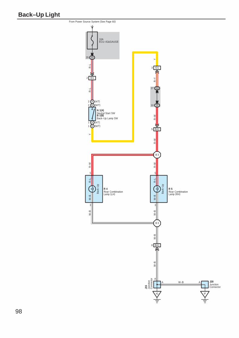
98
Back–Up Light
10AECU–IG&GAUGE
From Power Source System (See Page 60)
2S25
B2 (M/T)A2 (A/T)
A1 (A/T)B1 (M/T)
ID12
ID13
2Q27
2I10
3 3
5 5
Bac
k–U
p
Bac
k–U
p
W–B
R–L
R–L
W–B
R–W
R–W
W–B
W–B
R–W
R–Y
Y
R–L
R–L
N 1(A)
R 4 R 5
B 1(B)Back–Up Lamp SW
Neutral Start SW
Rear CombinationLamp (LH)
Rear CombinationLamp (RH)
Y
BA15
B 3R
–W
IF
JunctionConnector
J28A
B 3
IG
A
BA18
W–B
W–B
W–B
Junc
tion
Con
nect
or
J15
A
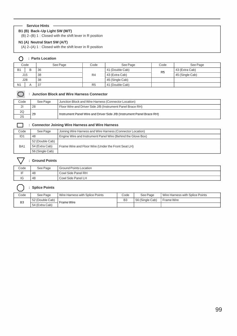
99
B1 (B) Back–Up Light SW (M/T)(B) 2–(B) 1 : Closed with the shift lever in R position
N1 (A) Neutral Start SW (A/T)(A) 2–(A) 1 : Closed with the shift lever in R position
: Parts Location
Code See Page Code See Page Code See Page
B1 B 36
R4
41 (Double Cab)R5
43 (Extra Cab)
J15 38 R4 43 (Extra Cab)R5
45 (Single Cab)
J28 38
R4
45 (Single Cab)
N1 A 37 R5 41 (Double Cab)
: Junction Block and Wire Harness Connector
Code See Page Junction Block and Wire Harness (Connector Location)
2I 28 Floor Wire and Driver Side J/B (Instrument Panel Brace RH)
2Q29 Instrument Panel Wire and Driver Side J/B (Instrument Panel Brace RH)
2S29 Instrument Panel Wire and Driver Side J/B (Instrument Panel Brace RH)
: Connector Joining Wire Harness and Wire Harness
Code See Page Joining Wire Harness and Wire Harness (Connector Location)
ID1 48 Engine Wire and Instrument Panel Wire (Behind the Glove Box)
BA1
52 (Double Cab)
Frame Wire and Floor Wire (Under the Front Seat LH)BA1 54 (Extra Cab) Frame Wire and Floor Wire (Under the Front Seat LH)BA1
56 (Single Cab)
Frame Wire and Floor Wire (Under the Front Seat LH)
: Ground Points
Code See Page Ground Points Location
IF 48 Cowl Side Panel RH
IG 48 Cowl Side Panel LH
: Splice Points
Code See Page Wire Harness with Splice Points Code See Page Wire Harness with Splice Points
B352 (Double Cab)
Frame WireB3 56 (Single Cab) Frame Wire
B354 (Extra Cab)
Frame Wire
Service Hints
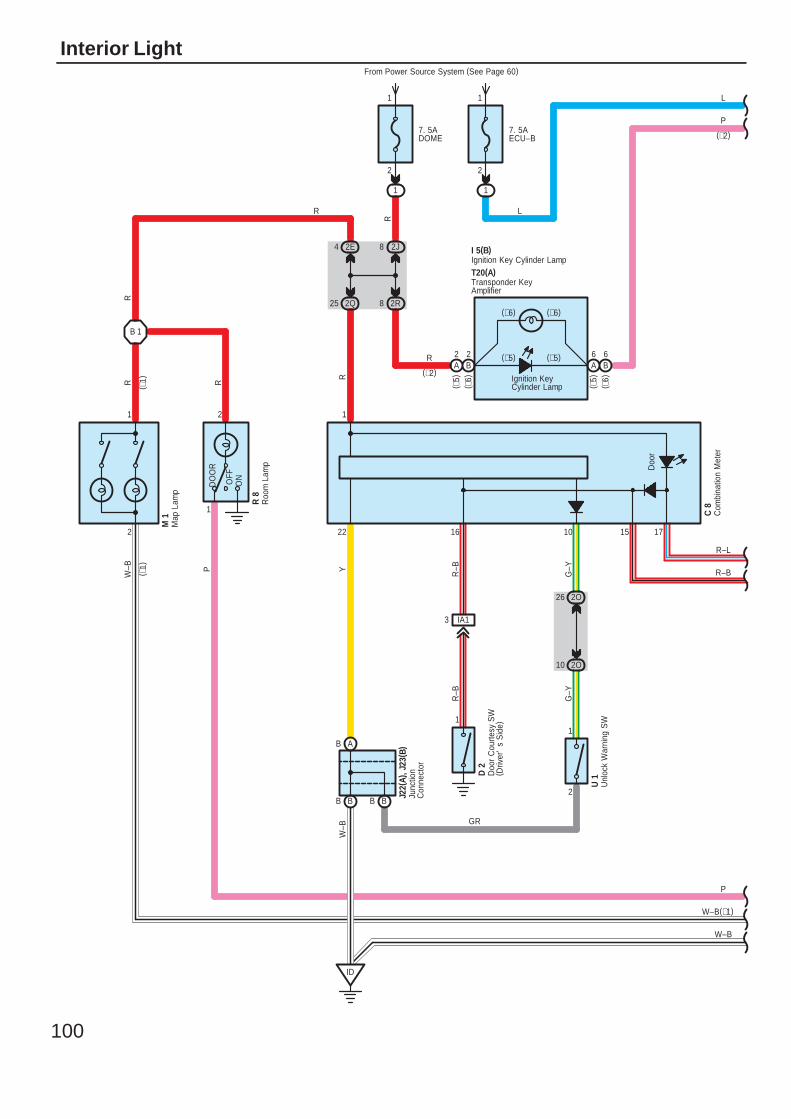
100
Interior Light
2O10
1
2
IA13
BB BB
ID
7. 5ADOME
From Power Source System (See Page 60)
1
2
1
2J82E4
2R8
7. 5AECU–B
1
2
1
B 1
W–B
W–B(∗1)
P
GR
R–B
R–L
L
G–Y
G–Y
R–B
R–B
R
RRW
–B Y
R L
W–B
R 8
M 1
R
2
1
22 16 10 15 17
1
1
21
P
J22(
A), J
23( B
)
( ∗1)
( ∗1)
DO
OR
OFF
ON
Doo
r
Junc
tion
Con
nect
or
Map
Lam
p
B A
RP
(∗2)
2Q25
Ignition KeyCylinder Lamp
Com
bina
tion
Met
erC
8
I 5(B)
R
(∗2)
2O26U
nloc
k W
arni
ng S
WU
1
Doo
r C
ourte
sy S
W( D
river
's
Sid
e)
D 2
Transponder KeyAmplifier
T20(A)
B2
A2
A6
B6
( ∗5)
( ∗6)
( ∗5)
( ∗6)
Roo
m L
amp
Ignition Key Cylinder Lamp
(∗6) (∗6)
(∗5) (∗5)
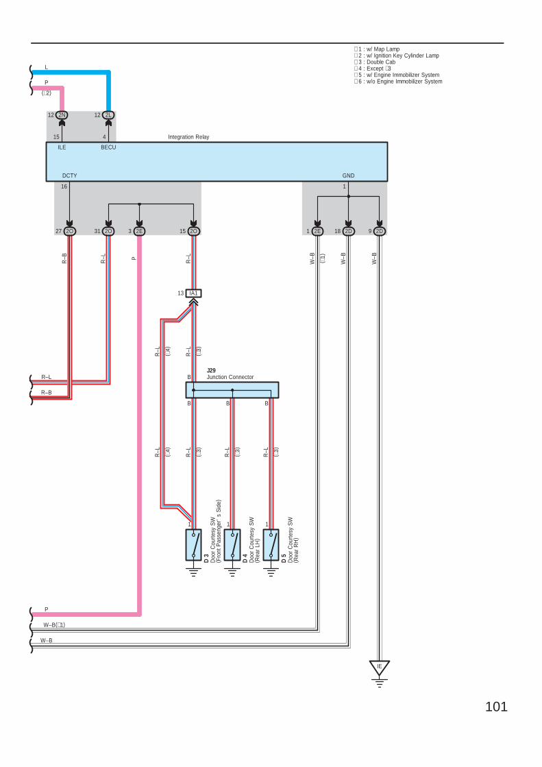
101
2E1 2D18 2D92O152O27 2O31
IA113
IE
111
B
BBB
2L12
L
R–L
R–B
W–B(∗1)
W–B
R–L
R–B
R–L
W–B
W–B
W–B
R–L
R–L
R–L
R–L
J29
Integration Relay
16 1
4
2E3
P
∗ 1 : w/ Map Lamp∗ 2 : w/ Ignition Key Cylinder Lamp∗ 3 : Double Cab
GNDDCTY
BECU
( ∗1)
Junction Connector
Doo
r C
ourte
sy S
W( F
ront
Pas
seng
er'
s S
ide)
D 3
Doo
r C
ourte
sy S
W( R
ear
LH)
D 4
Doo
r C
ourte
sy S
W( R
ear
RH
)
D 5
∗ 4 : Except ∗3
R–L
( ∗3)
( ∗4)
( ∗3)
( ∗3)
( ∗3)
P
2N12
15
(∗2)
ILE
P
( ∗4)
R–L
∗ 5 : w/ Engine Immobilizer System∗ 6 : w/o Engine Immobilizer System
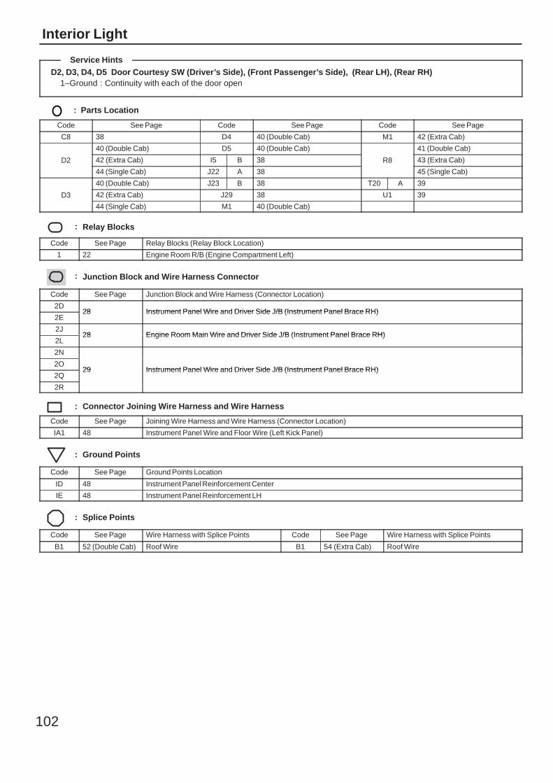
102
Interior Light
D2, D3, D4, D5 Door Courtesy SW (Driver’s Side), (Front Passenger’s Side), (Rear LH), (Rear RH)1–Ground : Continuity with each of the door open
: Parts Location
Code See Page Code See Page Code See Page
C8 38 D4 40 (Double Cab) M1 42 (Extra Cab)
D2
40 (Double Cab) D5 40 (Double Cab)
R8
41 (Double Cab)
D2 42 (Extra Cab) I5 B 38 R8 43 (Extra Cab)D2
44 (Single Cab) J22 A 38
R8
45 (Single Cab)
D3
40 (Double Cab) J23 B 38 T20 A 39
D3 42 (Extra Cab) J29 38 U1 39D3
44 (Single Cab) M1 40 (Double Cab)
: Relay Blocks
Code See Page Relay Blocks (Relay Block Location)
1 22 Engine Room R/B (Engine Compartment Left)
: Junction Block and Wire Harness Connector
Code See Page Junction Block and Wire Harness (Connector Location)
2D28 Instrument Panel Wire and Driver Side J/B (Instrument Panel Brace RH)
2E28 Instrument Panel Wire and Driver Side J/B (Instrument Panel Brace RH)
2J28 Engine Room Main Wire and Driver Side J/B (Instrument Panel Brace RH)
2L28 Engine Room Main Wire and Driver Side J/B (Instrument Panel Brace RH)
2N
29 Instrument Panel Wire and Driver Side J/B (Instrument Panel Brace RH)2O
29 Instrument Panel Wire and Driver Side J/B (Instrument Panel Brace RH)2Q
29 Instrument Panel Wire and Driver Side J/B (Instrument Panel Brace RH)
2R
: Connector Joining Wire Harness and Wire Harness
Code See Page Joining Wire Harness and Wire Harness (Connector Location)
IA1 48 Instrument Panel Wire and Floor Wire (Left Kick Panel)
: Ground Points
Code See Page Ground Points Location
ID 48 Instrument Panel Reinforcement Center
IE 48 Instrument Panel Reinforcement LH
: Splice Points
Code See Page Wire Harness with Splice Points Code See Page Wire Harness with Splice Points
B1 52 (Double Cab) Roof Wire B1 54 (Extra Cab) Roof Wire
Service Hints

103
Memo
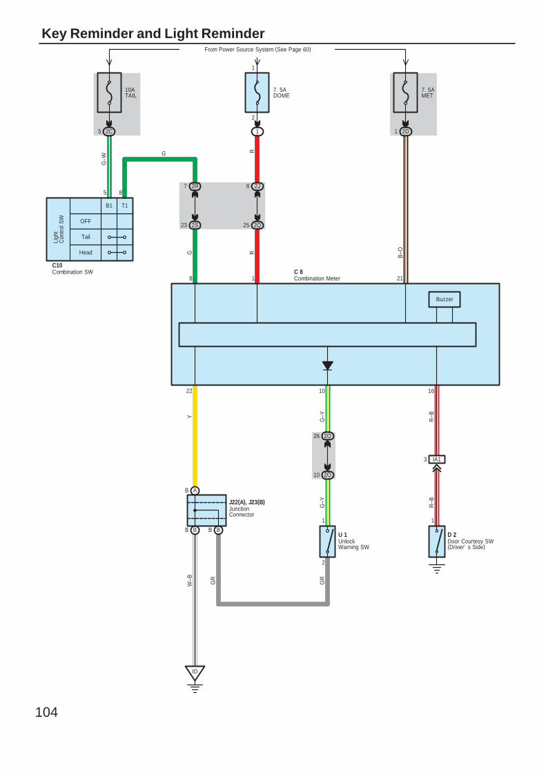
104
Key Reminder and Light Reminder
G
G–W
B–O
GR
W–B
Buzzer
RR
7. 5AMET
From Power Source System (See Page 60)
2D1
10ATAIL
2C5
7. 5ADOME
1
2
1
OFF
Tail
Head
Ligh
tC
ontro
l SW
85
C10
ID
BB BB
AB
J22(A), J23(B)
IA13
1
2O26
2O10
2
1
23 2S
7 2R
GR
G–Y
R–B
R–B
Y
G–Y
25 2Q
8 2J
22 10 16
8 1 21C 8
B1 T1
Combination MeterCombination SW
JunctionConnector
UnlockWarning SW
U 1Door Courtesy SW(Driver' s Side)
D 2
G
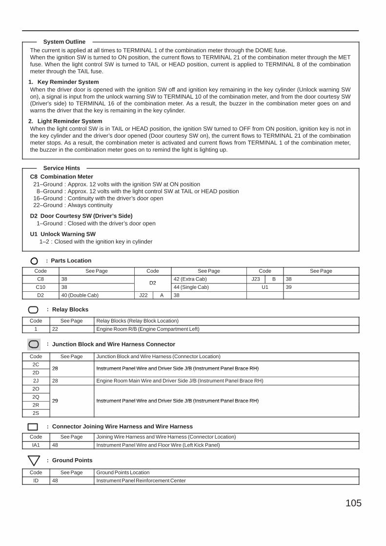
105
The current is applied at all times to TERMINAL 1 of the combination meter through the DOME fuse.When the ignition SW is turned to ON position, the current flows to TERMINAL 21 of the combination meter through the METfuse. When the light control SW is turned to TAIL or HEAD position, current is applied to TERMINAL 8 of the combinationmeter through the TAIL fuse.
1. Key Reminder SystemWhen the driver door is opened with the ignition SW off and ignition key remaining in the key cylinder (Unlock warning SWon), a signal is input from the unlock warning SW to TERMINAL 10 of the combination meter, and from the door courtesy SW(Driver’s side) to TERMINAL 16 of the combination meter. As a result, the buzzer in the combination meter goes on andwarns the driver that the key is remaining in the key cylinder.
2. Light Reminder SystemWhen the light control SW is in TAIL or HEAD position, the ignition SW turned to OFF from ON position, ignition key is not inthe key cylinder and the driver’s door opened (Door courtesy SW on), the current flows to TERMINAL 21 of the combinationmeter stops. As a result, the combination meter is activated and current flows from TERMINAL 1 of the combination meter,the buzzer in the combination meter goes on to remind the light is lighting up.
C8 Combination Meter21–Ground : Approx. 12 volts with the ignition SW at ON position
8–Ground : Approx. 12 volts with the light control SW at TAIL or HEAD position16–Ground : Continuity with the driver’s door open22–Ground : Always continuity
D2 Door Courtesy SW (Driver’s Side)1–Ground : Closed with the driver’s door open
U1 Unlock Warning SW1–2 : Closed with the ignition key in cylinder
: Parts Location
Code See Page Code See Page Code See Page
C8 38D2
42 (Extra Cab) J23 B 38
C10 38D2
44 (Single Cab) U1 39
D2 40 (Double Cab) J22 A 38
: Relay Blocks
Code See Page Relay Blocks (Relay Block Location)
1 22 Engine Room R/B (Engine Compartment Left)
: Junction Block and Wire Harness Connector
Code See Page Junction Block and Wire Harness (Connector Location)
2C28 Instrument Panel Wire and Driver Side J/B (Instrument Panel Brace RH)
2D28 Instrument Panel Wire and Driver Side J/B (Instrument Panel Brace RH)
2J 28 Engine Room Main Wire and Driver Side J/B (Instrument Panel Brace RH)
2O
29 Instrument Panel Wire and Driver Side J/B (Instrument Panel Brace RH)2Q
29 Instrument Panel Wire and Driver Side J/B (Instrument Panel Brace RH)2R
29 Instrument Panel Wire and Driver Side J/B (Instrument Panel Brace RH)
2S
: Connector Joining Wire Harness and Wire Harness
Code See Page Joining Wire Harness and Wire Harness (Connector Location)
IA1 48 Instrument Panel Wire and Floor Wire (Left Kick Panel)
: Ground Points
Code See Page Ground Points Location
ID 48 Instrument Panel Reinforcement Center
System Outline
Service Hints
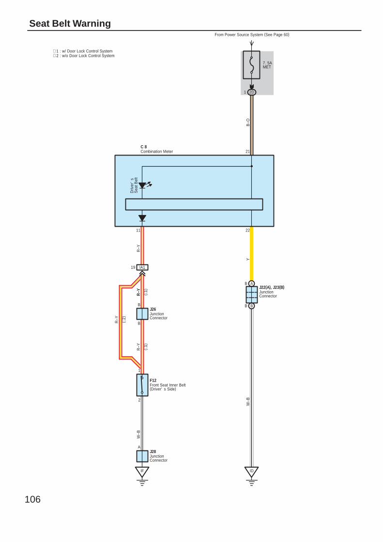
106
Seat Belt Warning
7. 5AMET
From Power Source System (See Page 60)
2D1
Driv
er'
sS
eat B
elt
2
1
IF
J28A
AB
BB
ID
B
B
21
2211
R–Y
Y
R–Y
W–B
W–B
B–O
R–Y
IA119
C 8
J26
F12
J22(A), J23(B)
Combination Meter
Front Seat Inner Belt(Driver' s Side)
JunctionConnector
JunctionConnector
JunctionConnector
∗ 2 : w/o Door Lock Control System∗ 1 : w/ Door Lock Control System
R–Y
R–Y ( ∗1)
( ∗1)
( ∗2)
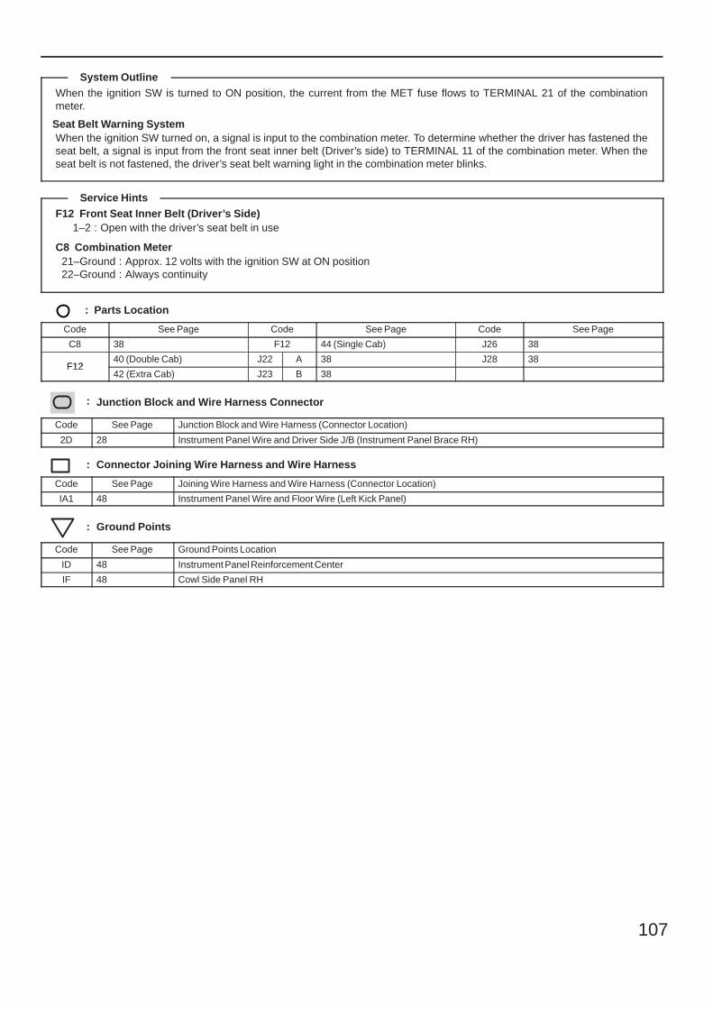
107
When the ignition SW is turned to ON position, the current from the MET fuse flows to TERMINAL 21 of the combinationmeter.
Seat Belt Warning SystemWhen the ignition SW turned on, a signal is input to the combination meter. To determine whether the driver has fastened theseat belt, a signal is input from the front seat inner belt (Driver’s side) to TERMINAL 11 of the combination meter. When theseat belt is not fastened, the driver’s seat belt warning light in the combination meter blinks.
F12 Front Seat Inner Belt (Driver’s Side)1–2 : Open with the driver’s seat belt in use
C8 Combination Meter21–Ground : Approx. 12 volts with the ignition SW at ON position22–Ground : Always continuity
: Parts Location
Code See Page Code See Page Code See Page
C8 38 F12 44 (Single Cab) J26 38
F1240 (Double Cab) J22 A 38 J28 38
F1242 (Extra Cab) J23 B 38
: Junction Block and Wire Harness Connector
Code See Page Junction Block and Wire Harness (Connector Location)
2D 28 Instrument Panel Wire and Driver Side J/B (Instrument Panel Brace RH)
: Connector Joining Wire Harness and Wire Harness
Code See Page Joining Wire Harness and Wire Harness (Connector Location)
IA1 48 Instrument Panel Wire and Floor Wire (Left Kick Panel)
: Ground Points
Code See Page Ground Points Location
ID 48 Instrument Panel Reinforcement Center
IF 48 Cowl Side Panel RH
System Outline
Service Hints
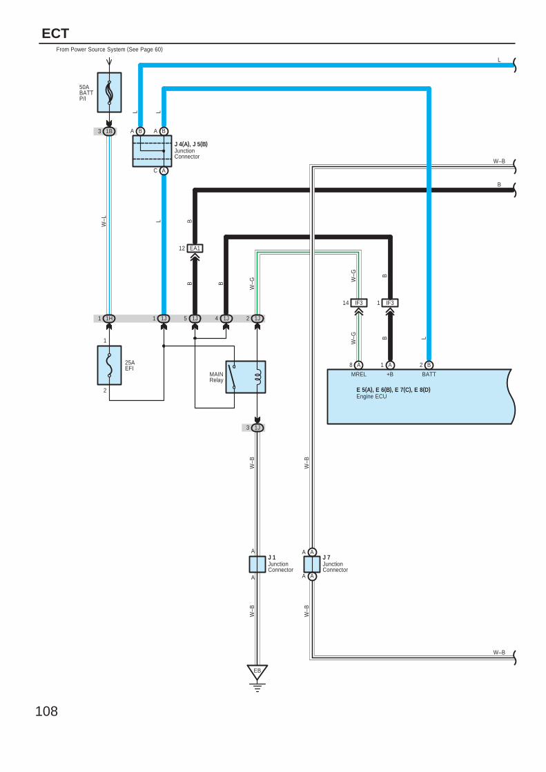
108
ECT
1
E 5(A), E 6(B), E 7(C), E 8(D)
1H
3 1J
8 A 1 A 2 B
EB
1 IF314 IF3
50ABATTP/I
From Power Source System (See Page 60)
1B3
W–L
A
5 1J
C
B
1 1J
L
BATTMREL +B
W–G
B
W–G
B
A
2
W–B
1J
W–B
W–G
L
B
2
L
25AEFI
1
A
A
MAINRelay
J 7
W–B
W–B
LBA
B
1J4
EA112
B
J 4(A), J 5(B)
J 1
L
Engine ECU
JunctionConnector
JunctionConnector
JunctionConnector
B
AA
AA
W–B
W–B
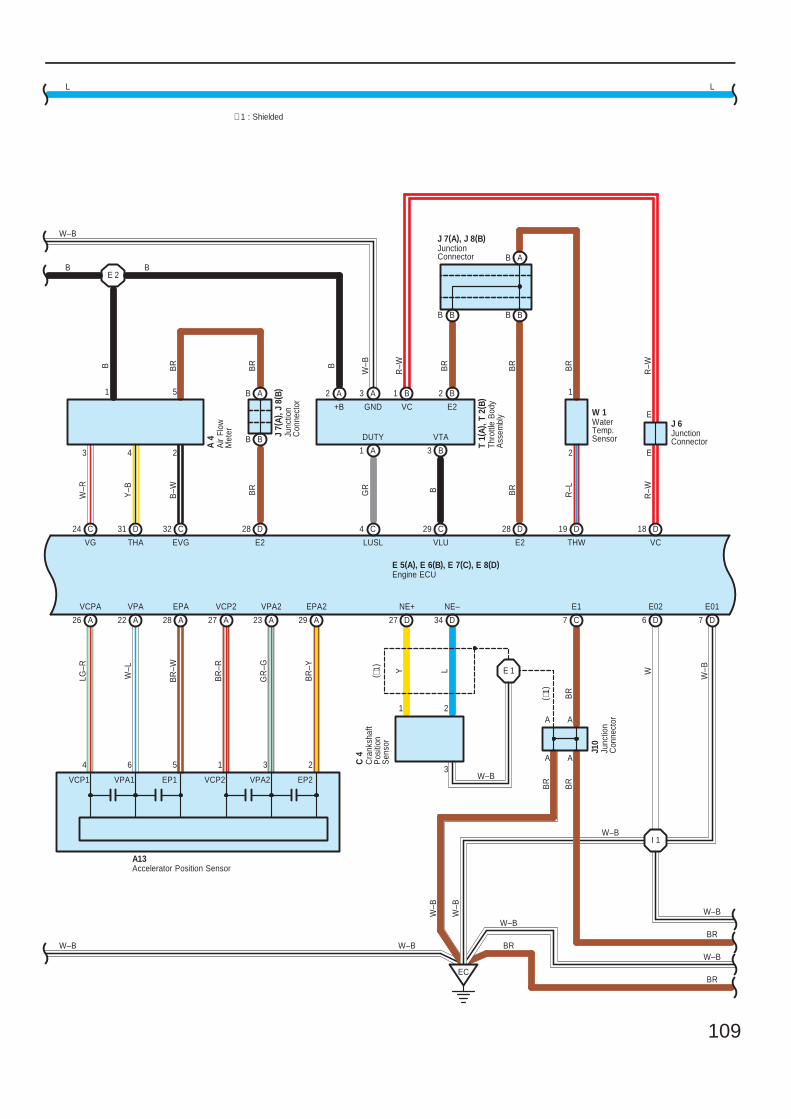
109
A26
VPA2
GR
–G
VPA2 EPA2
BR
–Y
VCP2
BR
–R
VCP2 EP2EP1
BR
–W
EPAVPA
W–L
VPA1VCP1
LG–R
VCPA
22 A A28 A27 A23
231564
A13
A29
W 1
BB
A
R–W
R–W
VC
B
E2
BR
BR
B
B
R–L
BR
THWVLU
BB
R
R–W
D18D28 19 DC29
E
E
1
2
∗ 1 : Shielded
E 5(A), E 6(B), E 7(C), E 8(D)
C727 D 34 D
EC
NE+
1
Y L
NE–
2
3
E1
BR
W–B
J 6
A
A
BR
W–B
LL
Accelerator Position Sensor
Engine ECU
JunctionConnector
WaterTemp. Sensor
JunctionConnector
J 7(A), J 8(B)
4
51
31 D
THA
Y–B
B BR
VG
3
W–R
24 C
2
EVG
B–W
32 C 28
BR
E2
D
AB
BB
B
BR
Junc
tion
Con
nect
or
J10
Cra
nksh
aft
Pos
ition
Sen
sor
C 4
E 1
W–B
( ∗1)
( ∗1)
A
W–B
BR
BR
BR
W W–B
E01E02
I 1
D6 D7
W–B
W–B
BR
W–B
W–B
W–B
Air
Flow
Met
er
A 4 Ju
nctio
nC
onne
ctor
J 7(
A), J
8( B
)
Thro
ttle
Bod
yA
ssem
bly
T 1(
A), T
2( B
)B1 B2
B3A1
A3A2
E2VCGND+B
VTADUTY
4 C
LUSL
GR
W–B
B
E 2B
W–B
A
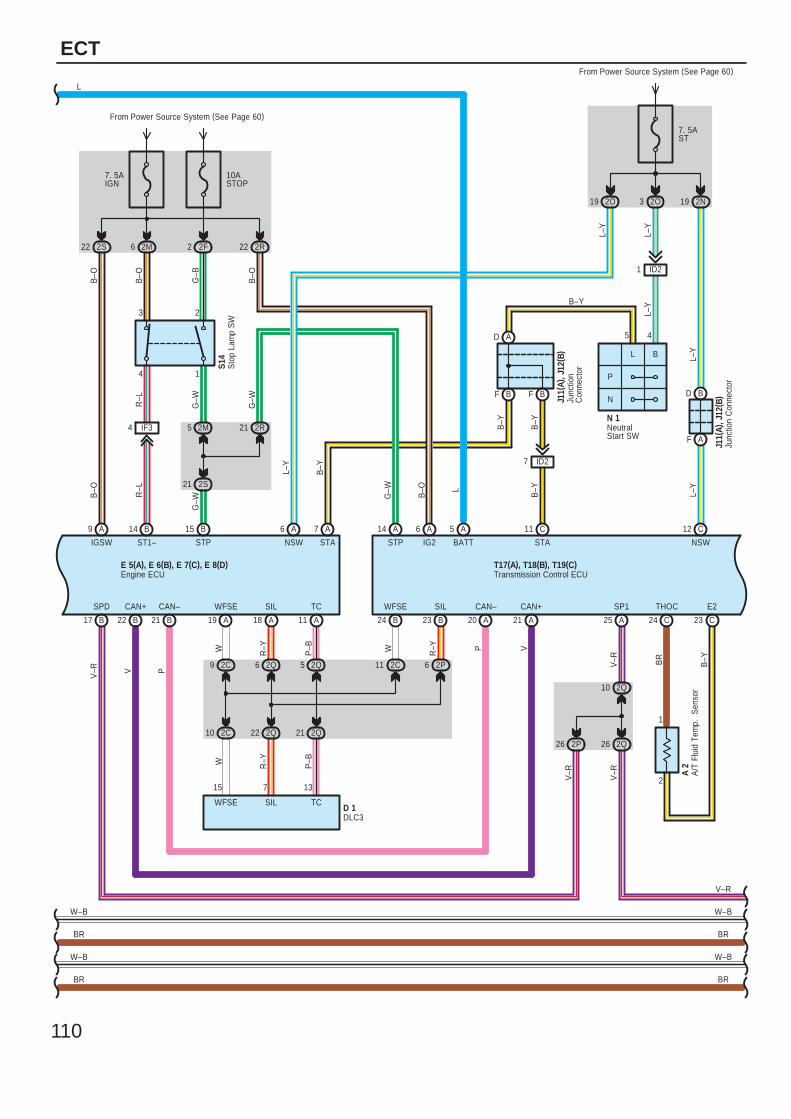
110
ECT
B–O
22 2R
7. 5AIGN
17 B
2M6
B–O
B–O
22 2S
B–O
SPD
V–R
IGSW
B9 A
ST1–
14
R–L
R–L
4
3
G–W
STP
IF34
B15
5
G–B
G–W
2M
2 2F
2
1
From Power Source System (See Page 60)
2R21
G–W
F A
D B
L–Y
NSW
12
BF
A
B–O
IG2
A5
V–R
6 A
26 2P
B–Y
BATT
L
G–W
STP
A14
From Power Source System (See Page 60)
T17(A), T18(B), T19(C)
W
11 2P62C
L
R–Y
B
WFSE SIL
B24 B23
C
L–Y
B–Y
F B
N 1
STA
L–Y
7. 5AST
2O3
L–Y
5 4
P
N
C11
1 ID2
B–Y
J11(
A), J
12( B
)
20 A 21 A
CAN–
V
CAN+
P
A 2
23 C24 C
1
2
B–YBR
D
B–Y
7 ID2
19 2N
V–R
SP1
A25
J11(
A), J
12( B
)
V–R
2Q10
2Q26
STA
B–Y
P–B
R–Y
6 2Q
22 2Q
5 2Q
21 2Q
V
CAN+
B
P
22
P–B
R–Y
WFSE
WFSE
W
TCSIL
TCSIL
A19 A11A18
2C10
2C9
W
21 B
CAN–
E 5(A), E 6(B), E 7(C), E 8(D)
7 A
15 137
D 1
L
V–R
DLC3
Engine ECU
Junc
tion
Con
nect
or
Junc
tion
Con
nect
or
NeutralStart SW
Transmission Control ECU
21 2S
THOC E2
10ASTOP
Sto
p La
mp
SW
S14
NSW
L–Y
6 A
2O19
L–Y
A/T
Flu
id T
emp.
S
enso
r
W–B
BR
W–B
BR
W–B
BR
W–B
BR
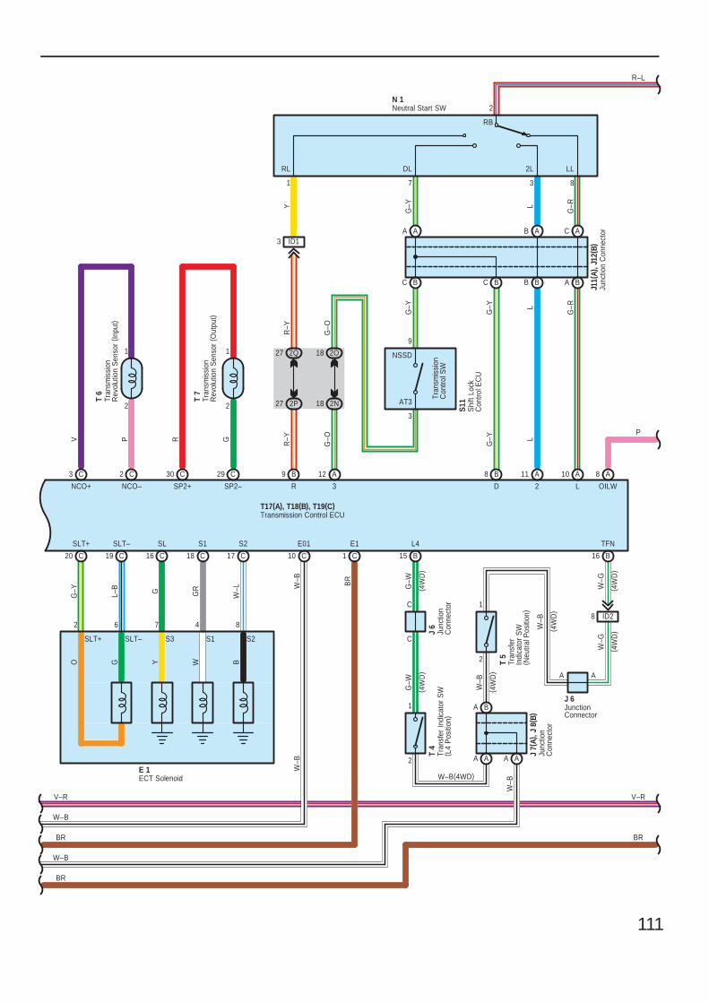
111
V P
NCO+ NCO–
C3 C2
17 C18 C16 C19 C20 C
29 CC30
2 4
SLT+
G–Y
6 7
SLT–
L–B
SL
G
W–L
S2
E 1
8
GR
S1
R G
SP2+ SP2–
BWYGO
8
W–B
E01
W–B
10 C
T17(A), T18(B), T19(C)
BR
E1
C1
V–R
BR
11 10
S2
L
L
2R
R–Y
9 B A A
P
R–L
B
DG
–Y
V–R
ECT Solenoid
Transmission Control ECU
Neutral Start SW
Junc
tion
Con
nect
or
18 2N
18 2O
A BB B
C AB A
27 2P
27 2Q
3 ID1
AT3
NSSD
9
3
YR
–Y
G–O
1 7 3 8
2
C
G–Y L
G–R
G–RL
G–Y
B
AA
B
Tran
smis
sion
Con
trol S
W
J11(
A), J
12( B
)
N 1
C
G–Y
RL DL 2L LL
RB
T 7
T 6
Shi
ft Lo
ckC
ontro
l EC
U
S11
C
C
G–W
L4
G–W
B15
Junc
tion
Con
nect
or
J 6
W–G
TFN
B16
2
1
2
1
AA
BA
AA
ID28
T 4
T 5
Junc
tion
Con
nect
or
J 7(
A), J
8( B
)
3
G–O
12 A
S3 S1SLT–SLT+
8
OILW
A
W–B(4WD)
W–G
W–B
W–B
( 4W
D)
( 4W
D)
( 4W
D)
( 4W
D) AA
JunctionConnector
J 6
( 4W
D)
( 4W
D)
Tran
smis
sion
Rev
olut
ion
Sen
sor
( Out
put)
Tran
smis
sion
Rev
olut
ion
Sen
sor
( Inpu
t)
Tran
sfer
Indi
cato
r S
W( L
4 P
ositi
on)
Tran
sfer
Indi
cato
r S
W( N
eutra
l Pos
ition
)
2
1
2
1
W–B
BR
W–B
BR
W–B
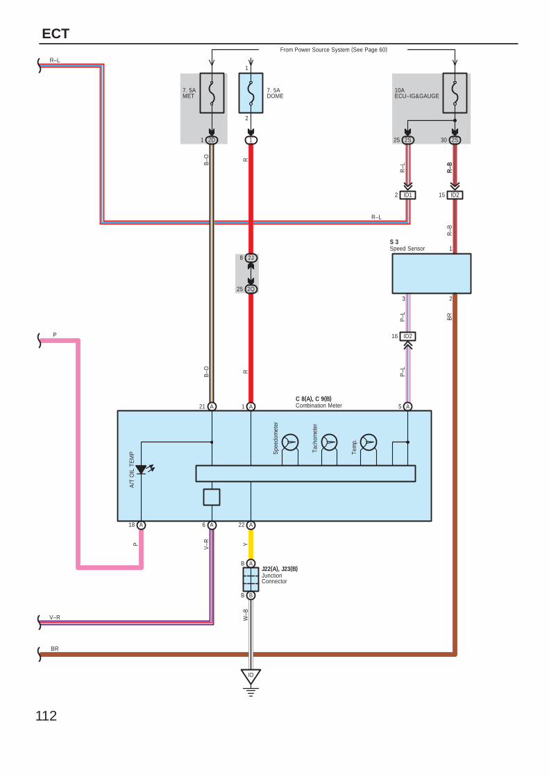
112
ECT
Speed Sensor
JunctionConnector
Combination Meter
R–L
1 2D
7. 5AMET
B–O
21 A
3
C 8(A), C 9(B)
6 A
5 A
16 ID2
V–R
R–B
S 3R
2
P–L
P–L
Tem
p.
Tach
omet
er
Spe
edom
eter
R
A1
1
R–B
R–B
1
2J8
2Q25
10AECU–IG&GAUGE
2S
ID215
30
7. 5ADOME
From Power Source System (See Page 60)
1
2
B B
B AJ22(A), J23(B)
22 A
W–B
Y
25 2S
R–LB
–O
BR
ID12
R–L
P
BR
V–R
ID
P
18 A
A/T
OIL
TE
MP
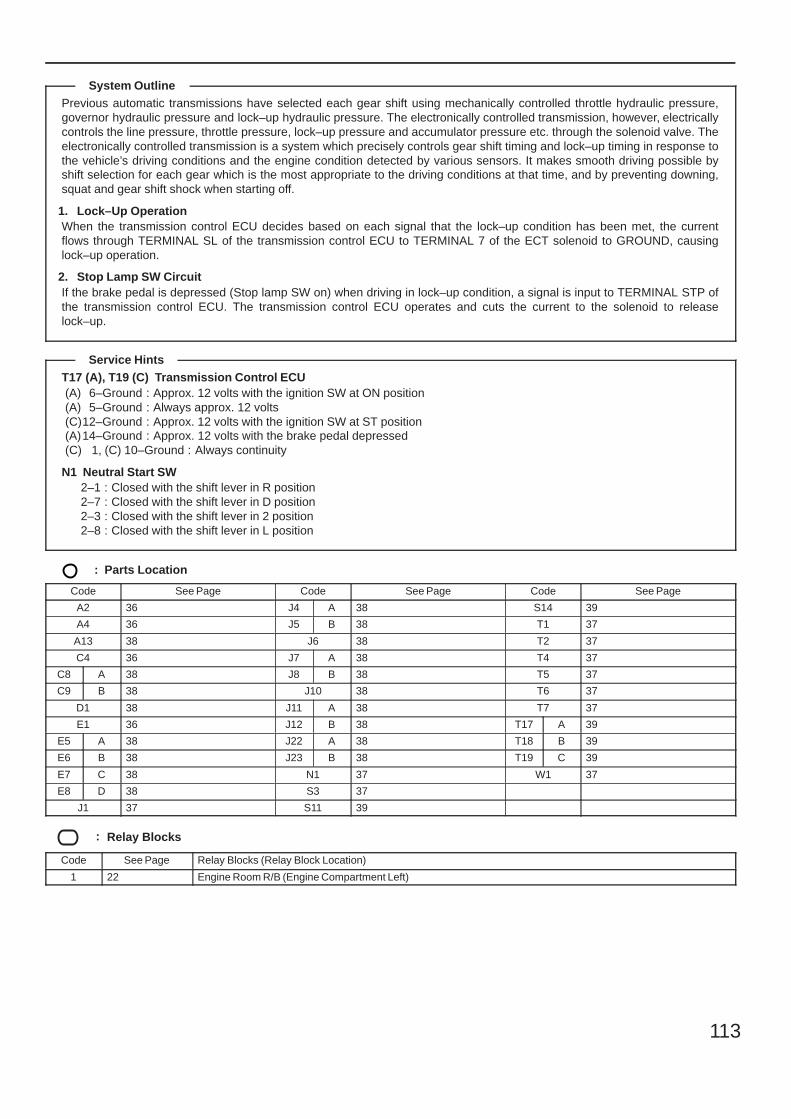
113
Previous automatic transmissions have selected each gear shift using mechanically controlled throttle hydraulic pressure,governor hydraulic pressure and lock–up hydraulic pressure. The electronically controlled transmission, however, electricallycontrols the line pressure, throttle pressure, lock–up pressure and accumulator pressure etc. through the solenoid valve. Theelectronically controlled transmission is a system which precisely controls gear shift timing and lock–up timing in response tothe vehicle’s driving conditions and the engine condition detected by various sensors. It makes smooth driving possible byshift selection for each gear which is the most appropriate to the driving conditions at that time, and by preventing downing,squat and gear shift shock when starting off.
1. Lock–Up OperationWhen the transmission control ECU decides based on each signal that the lock–up condition has been met, the currentflows through TERMINAL SL of the transmission control ECU to TERMINAL 7 of the ECT solenoid to GROUND, causinglock–up operation.
2. Stop Lamp SW CircuitIf the brake pedal is depressed (Stop lamp SW on) when driving in lock–up condition, a signal is input to TERMINAL STP ofthe transmission control ECU. The transmission control ECU operates and cuts the current to the solenoid to releaselock–up.
T17 (A), T19 (C) Transmission Control ECU(A) 6–Ground : Approx. 12 volts with the ignition SW at ON position(A) 5–Ground : Always approx. 12 volts(C)12–Ground : Approx. 12 volts with the ignition SW at ST position(A)14–Ground : Approx. 12 volts with the brake pedal depressed(C) 1, (C) 10–Ground : Always continuity
N1 Neutral Start SW2–1 : Closed with the shift lever in R position2–7 : Closed with the shift lever in D position2–3 : Closed with the shift lever in 2 position2–8 : Closed with the shift lever in L position
: Parts Location
Code See Page Code See Page Code See Page
A2 36 J4 A 38 S14 39
A4 36 J5 B 38 T1 37
A13 38 J6 38 T2 37
C4 36 J7 A 38 T4 37
C8 A 38 J8 B 38 T5 37
C9 B 38 J10 38 T6 37
D1 38 J11 A 38 T7 37
E1 36 J12 B 38 T17 A 39
E5 A 38 J22 A 38 T18 B 39
E6 B 38 J23 B 38 T19 C 39
E7 C 38 N1 37 W1 37
E8 D 38 S3 37
J1 37 S11 39
: Relay Blocks
Code See Page Relay Blocks (Relay Block Location)
1 22 Engine Room R/B (Engine Compartment Left)
System Outline
Service Hints
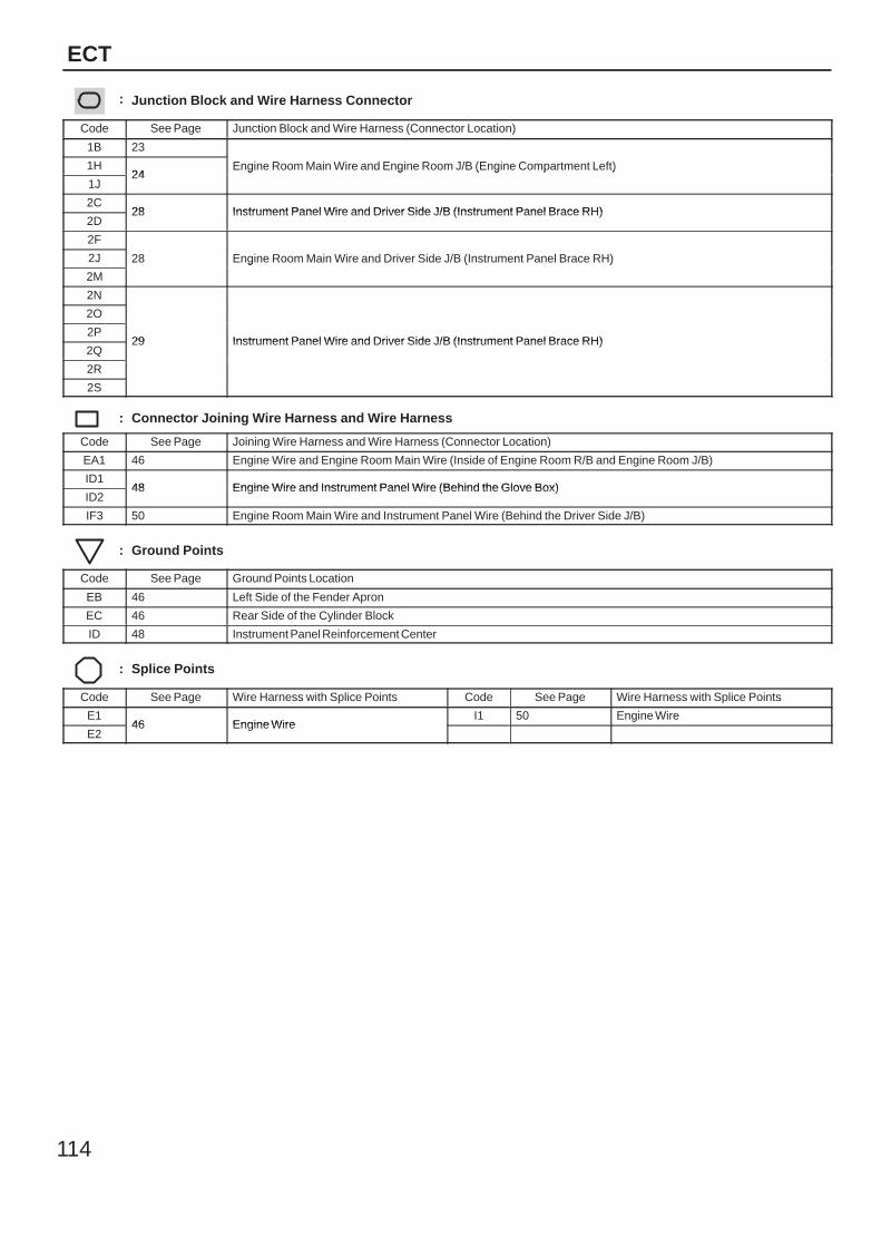
114
ECT
: Junction Block and Wire Harness Connector
Code See Page Junction Block and Wire Harness (Connector Location)
1B 23
Engine Room Main Wire and Engine Room J/B (Engine Compartment Left)1H24
Engine Room Main Wire and Engine Room J/B (Engine Compartment Left)
1J24
Engine Room Main Wire and Engine Room J/B (Engine Compartment Left)
2C28 Instrument Panel Wire and Driver Side J/B (Instrument Panel Brace RH)
2D28 Instrument Panel Wire and Driver Side J/B (Instrument Panel Brace RH)
2F
28 Engine Room Main Wire and Driver Side J/B (Instrument Panel Brace RH)2J 28 Engine Room Main Wire and Driver Side J/B (Instrument Panel Brace RH)
2M
28 Engine Room Main Wire and Driver Side J/B (Instrument Panel Brace RH)
2N
29 Instrument Panel Wire and Driver Side J/B (Instrument Panel Brace RH)
2O
29 Instrument Panel Wire and Driver Side J/B (Instrument Panel Brace RH)2P
29 Instrument Panel Wire and Driver Side J/B (Instrument Panel Brace RH)2Q
29 Instrument Panel Wire and Driver Side J/B (Instrument Panel Brace RH)
2R
2S
: Connector Joining Wire Harness and Wire Harness
Code See Page Joining Wire Harness and Wire Harness (Connector Location)
EA1 46 Engine Wire and Engine Room Main Wire (Inside of Engine Room R/B and Engine Room J/B)
ID148 Engine Wire and Instrument Panel Wire (Behind the Glove Box)
ID248 Engine Wire and Instrument Panel Wire (Behind the Glove Box)
IF3 50 Engine Room Main Wire and Instrument Panel Wire (Behind the Driver Side J/B)
: Ground Points
Code See Page Ground Points Location
EB 46 Left Side of the Fender Apron
EC 46 Rear Side of the Cylinder Block
ID 48 Instrument Panel Reinforcement Center
: Splice Points
Code See Page Wire Harness with Splice Points Code See Page Wire Harness with Splice Points
E146 Engine Wire
I1 50 Engine Wire
E246 Engine Wire

115
Memo
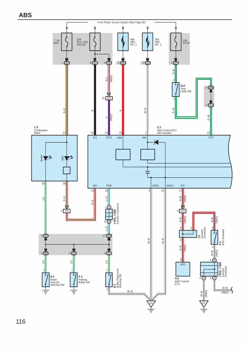
116
ABS
IG1
25
B–O B
23
R
1
W–R
G–W
STP
10
W–B
W–B
18
PKB
L–O
L–O
AB
S
Bra
ke
R–G
3836
21
R–G
13 2 24
WA
+BM +BS
GND1 GND2
1C2
40AABSNO. 1
From Power Source System (See Page 60)
1B2
10AECU–IG&GAUGE
2L8
7. 5AMET
2D1
C 8 S 2
EA
S14
2L
5
5
G–B
G–W
2M
2 2F
2
1
11
LG
LG LG
2
1
LG
AI
BD
J 4(
A), J
5( B
)
2K12M1 2L1
B 3 P 2
IF23
2S1
W–B
CombinationMeter
Junc
tion
Con
nect
or
ParkingBrake SW
Skid Control ECUwith Actuator
StopLamp SW
EC
W–B
2S17
R–B
EXI
17
2K4
IG110
R–L
V
22
EXI2
EA15
Bra
ke F
luid
Lev
elW
arni
ng S
W
B 2
D
D
8
3
R–B
R–B
R–B
Junc
tion
Con
nect
or
J 6
F14
ADD
( 4W
D)
( 4W
D)
( 4W
D)
( 4W
D)
( 4W
D)
BrakeVacuumWarning SW
4WD ControlECU
( 4W
D)
( 4W
D)
30AABSNO. 2
10ASTOP
AD
D A
cutu
ator
A 3
4
AA AA
BA
J 8(
A), J
9( B
)Ju
nctio
nC
onne
ctor
W–B
(4WD)
W–B
( 4W
D)
D
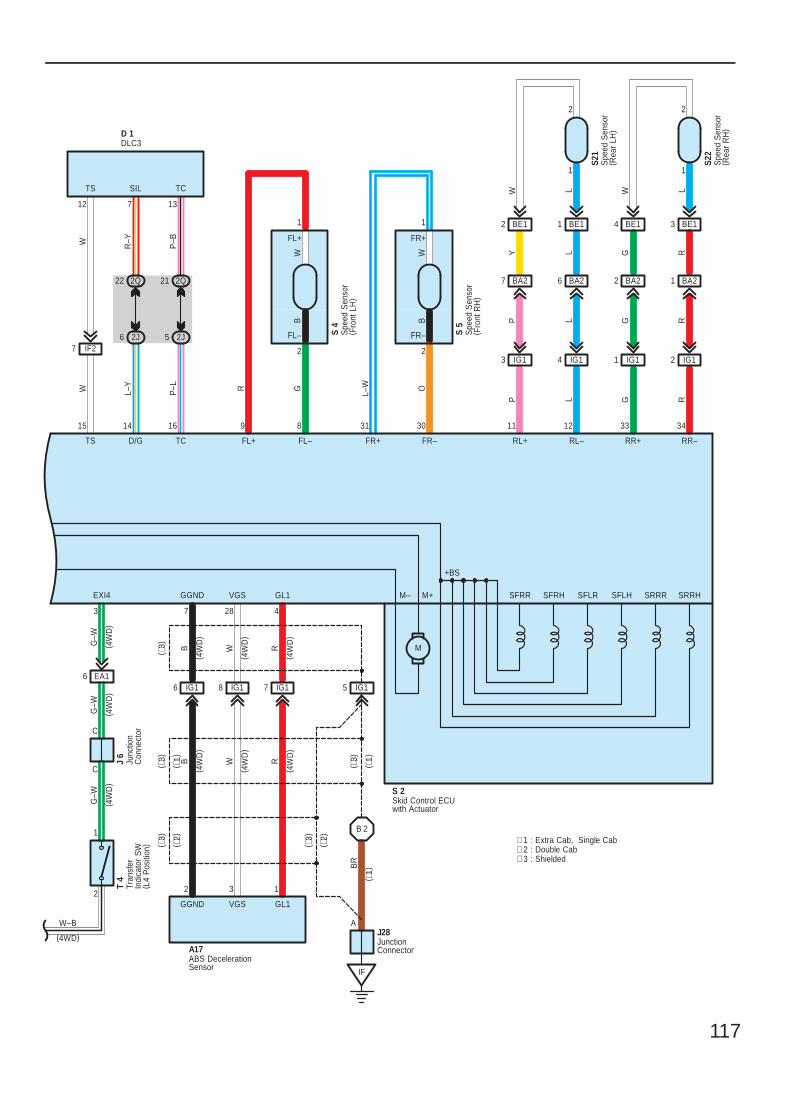
117
W
TS
15
L–Y
D/G
14
P–L
TC
16 9
FL+
R
YP
8
FL–
G
31
FR+
L–W
L
WP
L
30
FR–
O
M–
12
RL–RL+
11 34
RR–RR+
33
SRRR SRRHSFLHSFLRSFRHSFRR
M
+BS
M+
2
1
LL
G R
GG
LW
RR
S 2
BA21BA22BA26BA27
IG12IG11IG14IG13
S21
S22
IF27
12
W
TS SIL
7
TC
13
R–Y
P–B
2Q21
2J5
2Q22
2J6
D 1DLC3
Skid Control ECUwith Actuator
Spe
ed S
enso
r( R
ear
LH)
Spe
ed S
enso
r( R
ear
RH
)
Spe
ed S
enso
r( F
ront
LH
)
S 4
Spe
ed S
enso
r( F
ront
RH
)
S 5
IG15IG17IG18IG16
B 2
IF
JunctionConnector
J28A
132
RWBB W R
4287
( ∗3)
( ∗3)
BR
GL1VGSGGND
A17
GL1VGSGGND
EA16
C
C
2
1
3
G–W
G–W
G–W
EXI4
Junc
tion
Con
nect
or
J 6
T 4
BE13BE14BE11BE12
1
2
1
2
FR–
FR+
BW
1
2
WB
FL+
FL–
( 4W
D)
( 4W
D)
( 4W
D)
ABS DecelerationSensor
Tran
sfer
Indi
cato
r S
W( L
4 P
ositi
on)
W–B
(4WD)
( 4W
D)
( 4W
D)
( 4W
D)
( 4W
D)
( 4W
D)
( 4W
D)
∗ 1 : Extra Cab, Single Cab∗ 2 : Double Cab∗ 3 : Shielded
( ∗3)
( ∗3)
( ∗3)
( ∗1)
( ∗2)
( ∗2)
( ∗1)
( ∗1)
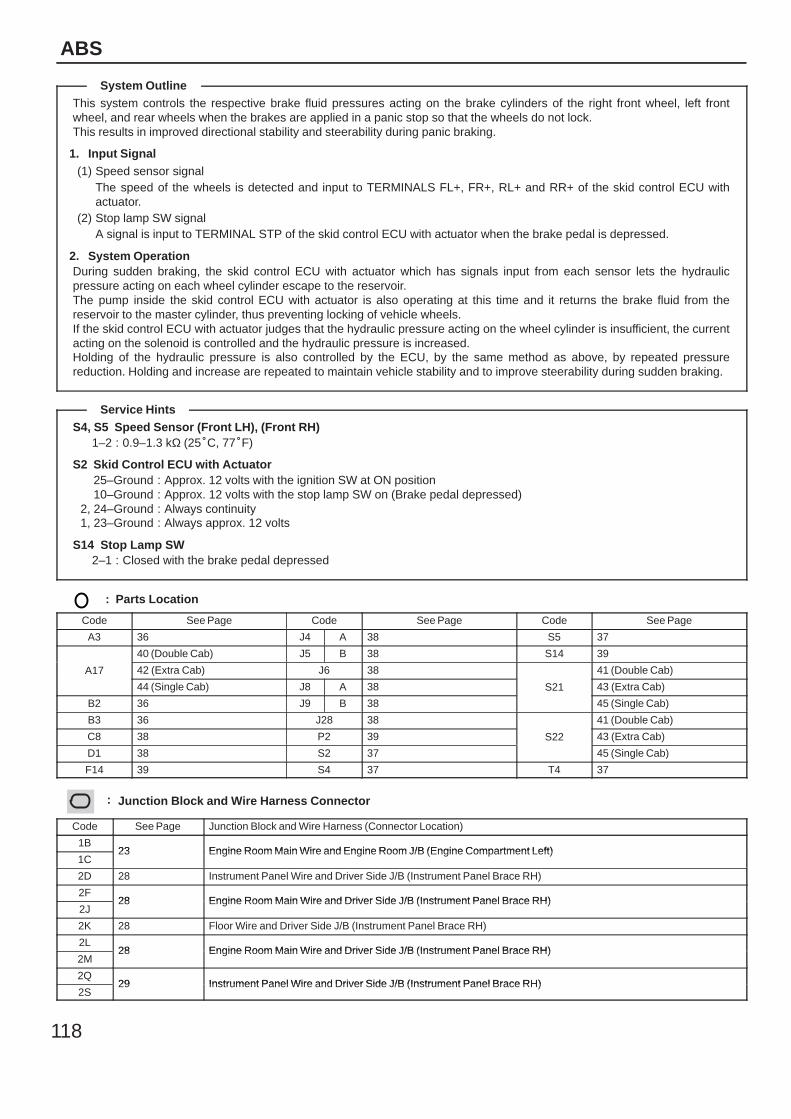
118
ABS
This system controls the respective brake fluid pressures acting on the brake cylinders of the right front wheel, left frontwheel, and rear wheels when the brakes are applied in a panic stop so that the wheels do not lock.This results in improved directional stability and steerability during panic braking.
1. Input Signal(1) Speed sensor signal
The speed of the wheels is detected and input to TERMINALS FL+, FR+, RL+ and RR+ of the skid control ECU withactuator.
(2) Stop lamp SW signalA signal is input to TERMINAL STP of the skid control ECU with actuator when the brake pedal is depressed.
2. System OperationDuring sudden braking, the skid control ECU with actuator which has signals input from each sensor lets the hydraulicpressure acting on each wheel cylinder escape to the reservoir.The pump inside the skid control ECU with actuator is also operating at this time and it returns the brake fluid from thereservoir to the master cylinder, thus preventing locking of vehicle wheels.If the skid control ECU with actuator judges that the hydraulic pressure acting on the wheel cylinder is insufficient, the currentacting on the solenoid is controlled and the hydraulic pressure is increased.Holding of the hydraulic pressure is also controlled by the ECU, by the same method as above, by repeated pressurereduction. Holding and increase are repeated to maintain vehicle stability and to improve steerability during sudden braking.
S4, S5 Speed Sensor (Front LH), (Front RH)1–2 : 0.9–1.3 kΩ (25C, 77F)
S2 Skid Control ECU with Actuator25–Ground : Approx. 12 volts with the ignition SW at ON position10–Ground : Approx. 12 volts with the stop lamp SW on (Brake pedal depressed)
2, 24–Ground : Always continuity1, 23–Ground : Always approx. 12 volts
S14 Stop Lamp SW2–1 : Closed with the brake pedal depressed
: Parts Location
Code See Page Code See Page Code See Page
A3 36 J4 A 38 S5 37
A17
40 (Double Cab) J5 B 38 S14 39
A17 42 (Extra Cab) J6 38
S21
41 (Double Cab)A17
44 (Single Cab) J8 A 38 S21 43 (Extra Cab)
B2 36 J9 B 38
S21
45 (Single Cab)
B3 36 J28 38
S22
41 (Double Cab)
C8 38 P2 39 S22 43 (Extra Cab)
D1 38 S2 37
S22
45 (Single Cab)
F14 39 S4 37 T4 37
: Junction Block and Wire Harness Connector
Code See Page Junction Block and Wire Harness (Connector Location)
1B23 Engine Room Main Wire and Engine Room J/B (Engine Compartment Left)
1C23 Engine Room Main Wire and Engine Room J/B (Engine Compartment Left)
2D 28 Instrument Panel Wire and Driver Side J/B (Instrument Panel Brace RH)
2F28 Engine Room Main Wire and Driver Side J/B (Instrument Panel Brace RH)
2J28 Engine Room Main Wire and Driver Side J/B (Instrument Panel Brace RH)
2K 28 Floor Wire and Driver Side J/B (Instrument Panel Brace RH)
2L28 Engine Room Main Wire and Driver Side J/B (Instrument Panel Brace RH)
2M28 Engine Room Main Wire and Driver Side J/B (Instrument Panel Brace RH)
2Q29 Instrument Panel Wire and Driver Side J/B (Instrument Panel Brace RH)
2S29 Instrument Panel Wire and Driver Side J/B (Instrument Panel Brace RH)
System Outline
Service Hints
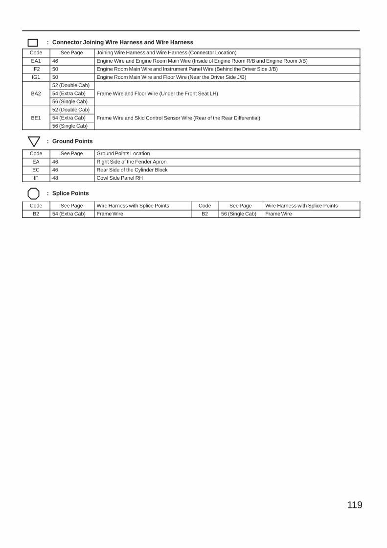
119
: Connector Joining Wire Harness and Wire Harness
Code See Page Joining Wire Harness and Wire Harness (Connector Location)
EA1 46 Engine Wire and Engine Room Main Wire (Inside of Engine Room R/B and Engine Room J/B)
IF2 50 Engine Room Main Wire and Instrument Panel Wire (Behind the Driver Side J/B)
IG1 50 Engine Room Main Wire and Floor Wire (Near the Driver Side J/B)
BA2
52 (Double Cab)
Frame Wire and Floor Wire (Under the Front Seat LH)BA2 54 (Extra Cab) Frame Wire and Floor Wire (Under the Front Seat LH)BA2
56 (Single Cab)
Frame Wire and Floor Wire (Under the Front Seat LH)
BE1
52 (Double Cab)
Frame Wire and Skid Control Sensor Wire (Rear of the Rear Differential)BE1 54 (Extra Cab) Frame Wire and Skid Control Sensor Wire (Rear of the Rear Differential)BE1
56 (Single Cab)
Frame Wire and Skid Control Sensor Wire (Rear of the Rear Differential)
: Ground Points
Code See Page Ground Points Location
EA 46 Right Side of the Fender Apron
EC 46 Rear Side of the Cylinder Block
IF 48 Cowl Side Panel RH
: Splice Points
Code See Page Wire Harness with Splice Points Code See Page Wire Harness with Splice Points
B2 54 (Extra Cab) Frame Wire B2 56 (Single Cab) Frame Wire

120
Memo
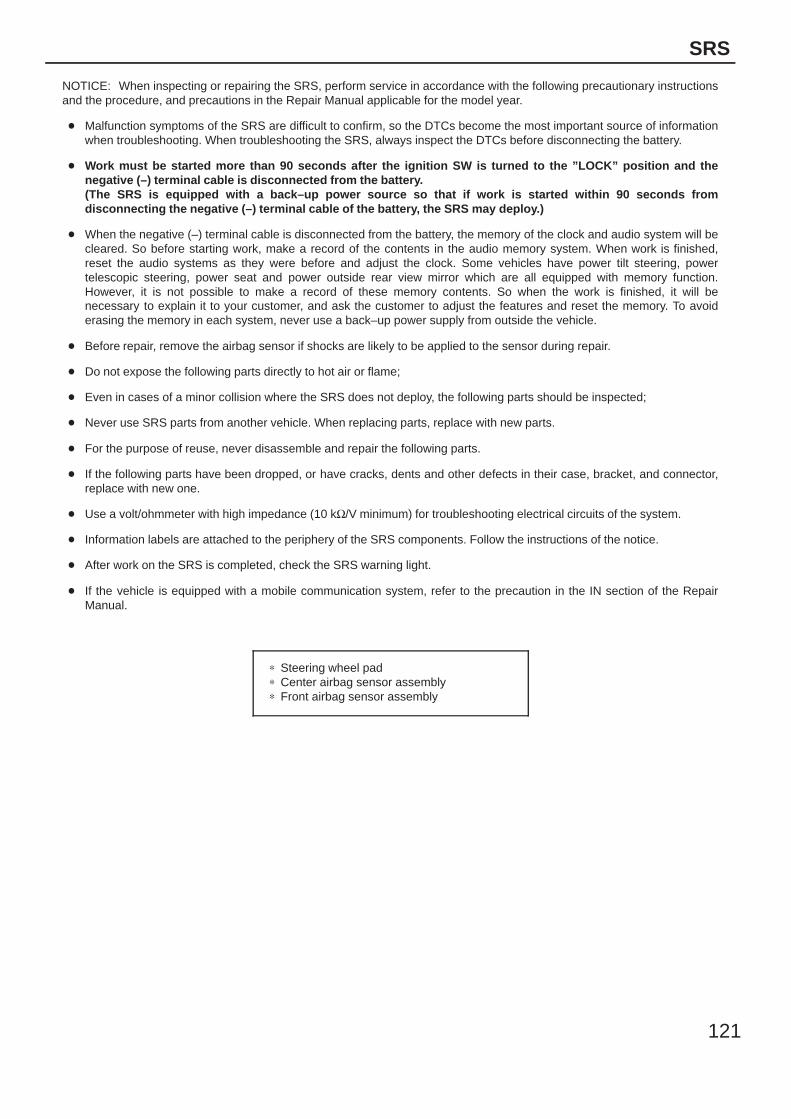
121
SRS
NOTICE: When inspecting or repairing the SRS, perform service in accordance with the following precautionary instructionsand the procedure, and precautions in the Repair Manual applicable for the model year.
Malfunction symptoms of the SRS are difficult to confirm, so the DTCs become the most important source of informationwhen troubleshooting. When troubleshooting the SRS, always inspect the DTCs before disconnecting the battery.
Work must be started more than 90 seconds after the ignition SW is turned to the ”LOCK” position and thenegative (–) terminal cable is disconnected from the battery.(The SRS is equipped with a back–up power source so that if work is started within 90 seconds fromdisconnecting the negative (–) terminal cable of the battery, the SRS may deploy.)
When the negative (–) terminal cable is disconnected from the battery, the memory of the clock and audio system will becleared. So before starting work, make a record of the contents in the audio memory system. When work is finished,reset the audio systems as they were before and adjust the clock. Some vehicles have power tilt steering, powertelescopic steering, power seat and power outside rear view mirror which are all equipped with memory function.However, it is not possible to make a record of these memory contents. So when the work is finished, it will benecessary to explain it to your customer, and ask the customer to adjust the features and reset the memory. To avoiderasing the memory in each system, never use a back–up power supply from outside the vehicle.
Before repair, remove the airbag sensor if shocks are likely to be applied to the sensor during repair.
Do not expose the following parts directly to hot air or flame;
Even in cases of a minor collision where the SRS does not deploy, the following parts should be inspected;
Never use SRS parts from another vehicle. When replacing parts, replace with new parts.
For the purpose of reuse, never disassemble and repair the following parts.
If the following parts have been dropped, or have cracks, dents and other defects in their case, bracket, and connector,replace with new one.
Use a volt/ohmmeter with high impedance (10 kΩ/V minimum) for troubleshooting electrical circuits of the system.
Information labels are attached to the periphery of the SRS components. Follow the instructions of the notice.
After work on the SRS is completed, check the SRS warning light.
If the vehicle is equipped with a mobile communication system, refer to the precaution in the IN section of the RepairManual.
∗ Steering wheel pad∗ Center airbag sensor assembly∗ Front airbag sensor assembly
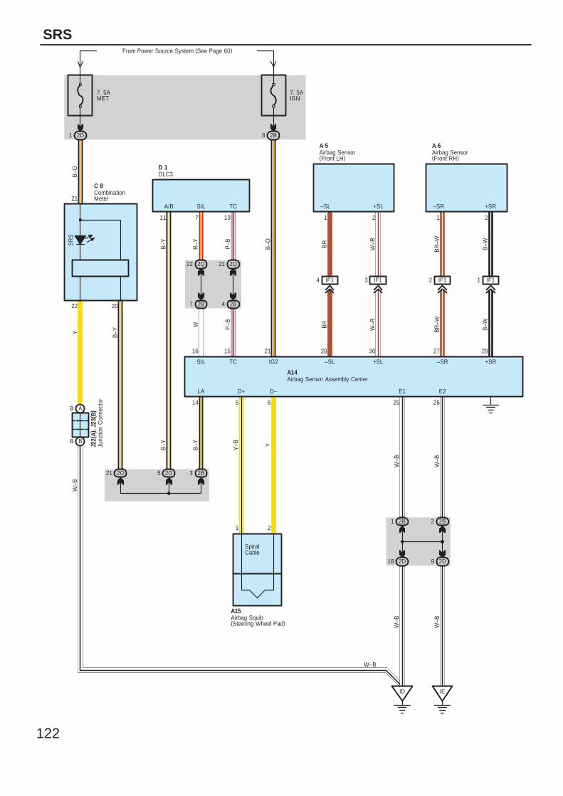
122
SRS
7. 5AMET
From Power Source System (See Page 60)
2D1
SR
S
7. 5AIGN
2B8
2B32O21 2O5
2Q22
2B7
2Q21
2B4
IF14 IF13 IF12 IF11
1 22B1
2D18
2B2
2D9
ID IE
AB
BB
7 1311
2022
14 5 6 25 26
292730282116 15
21
2121
+SR+SL–SL –SRSIL TCA/B
LA D+ D– E1 E2
+SR–SR+SL–SLIG2SIL TC
B–W
BR
–W
W–RBR
B–O
B–W
BR
–W
W–RBR
R–Y
P–B
B–Y
W P–B
B–O
B–YY
W–B
W–B
W–B
W–B
YY–B
B–Y
B–Y
W–B
W–B
A 6A 5
D 1
A15
A14
J22(
A), J
23( B
)
C 8
Airbag Sensor(Front LH)
Airbag Sensor(Front RH)
Airbag Sensor Assembly Center
Airbag Squib(Steering Wheel Pad)
CombinationMeter
DLC3
Junc
tion
Con
nect
or
SpiralCable
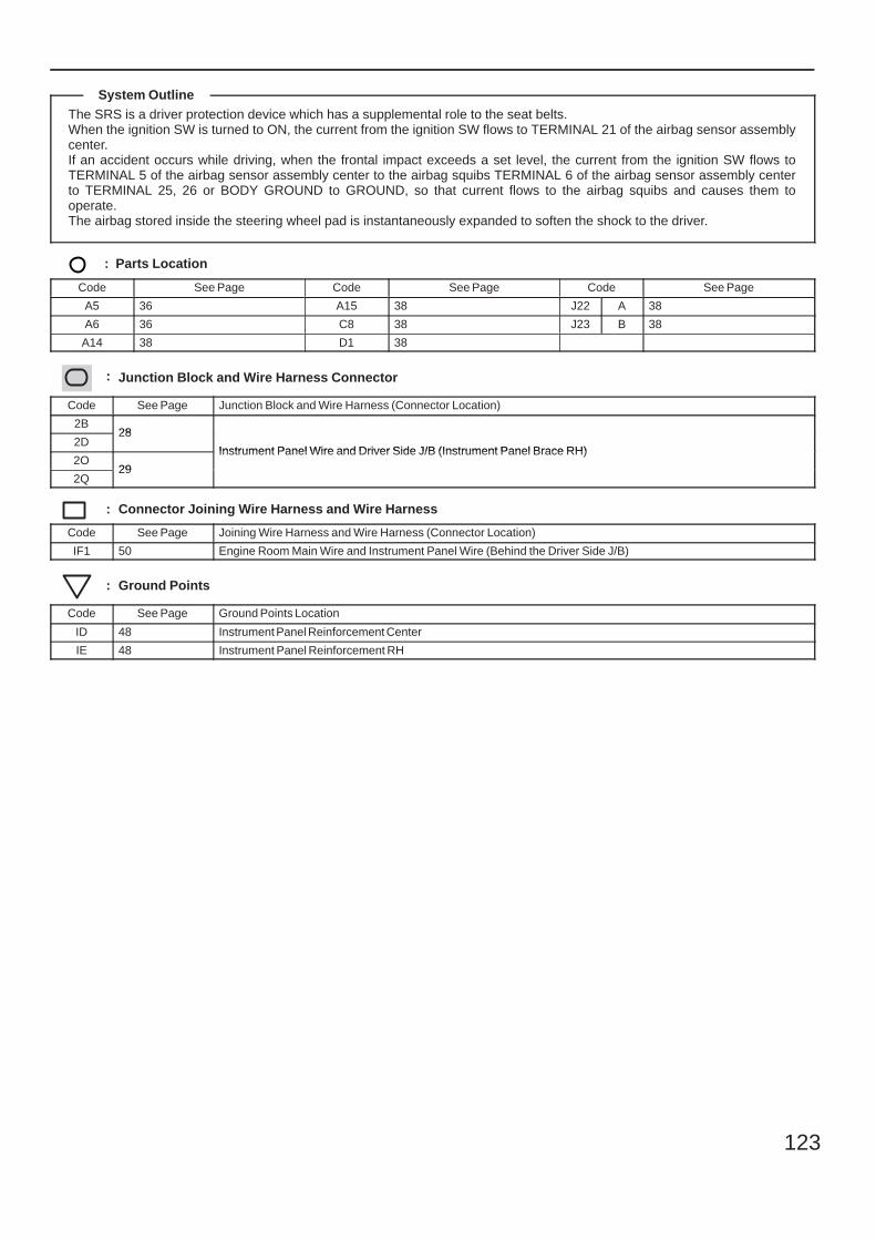
123
The SRS is a driver protection device which has a supplemental role to the seat belts.When the ignition SW is turned to ON, the current from the ignition SW flows to TERMINAL 21 of the airbag sensor assemblycenter.If an accident occurs while driving, when the frontal impact exceeds a set level, the current from the ignition SW flows toTERMINAL 5 of the airbag sensor assembly center to the airbag squibs TERMINAL 6 of the airbag sensor assembly centerto TERMINAL 25, 26 or BODY GROUND to GROUND, so that current flows to the airbag squibs and causes them tooperate.The airbag stored inside the steering wheel pad is instantaneously expanded to soften the shock to the driver.
: Parts Location
Code See Page Code See Page Code See Page
A5 36 A15 38 J22 A 38
A6 36 C8 38 J23 B 38
A14 38 D1 38
: Junction Block and Wire Harness Connector
Code See Page Junction Block and Wire Harness (Connector Location)
2B28
Instrument Panel Wire and Driver Side J/B (Instrument Panel Brace RH)2D
28
Instrument Panel Wire and Driver Side J/B (Instrument Panel Brace RH)2O
29
Instrument Panel Wire and Driver Side J/B (Instrument Panel Brace RH)
2Q29
: Connector Joining Wire Harness and Wire Harness
Code See Page Joining Wire Harness and Wire Harness (Connector Location)
IF1 50 Engine Room Main Wire and Instrument Panel Wire (Behind the Driver Side J/B)
: Ground Points
Code See Page Ground Points Location
ID 48 Instrument Panel Reinforcement Center
IE 48 Instrument Panel Reinforcement RH
System Outline
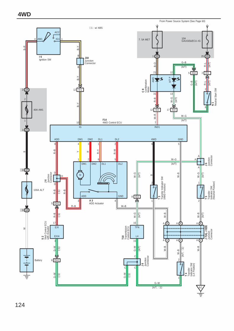
124
4WD
Battery
100A ALT
1
2
40A AM1
2A2
1F1
1A1
2G1
4 1AM1
ACC
IG1
Ignition SWI 6
B
B
ID112
AA AA
BA BA
EC
AA
D
D
EA15
EA16
C C
C
Ski
d C
ontro
l EC
Uw
ith A
ctua
tor
S 2
Junc
tion
Con
nect
or
J 7(
A), J
8( B
)
Junc
tion
Con
nect
or
J 6
JunctionConnector
J18
3 15
1
1
6 58
710
17
2
2
ADD GND4WD
L4EXI4
B–Y
B–Y
B–Y
B–R
BW
G–W
G–W
W–B
W–B W
–B
B
W–B
R–B
R–B
R–B
IND1IG
EXI
F14
G–W
BA
4
G–W
G–W
ID28
2
1
T 5
A
AW–G
W–G
W–G
W–B
4WD Control ECU
Tran
sfer
Indi
cato
r S
W( N
eutra
l Pos
ition
)
10AGAUGE&ECU–IG
2S25
ID12
6
2
R–L
R–L
1 2D
From Power Source System (See Page 60)
7. 5A MET
A/T
P
12 ID2
Neu
tral S
tart
SW
N 1
31
21
B–O
R–B
W–R
4WD
17 ID2
13
12
W–G
Com
bina
tion
Met
er
C 8
G–B
1 2 6 5
Y R R–Y
R–W
DM1 DM2 DL1 DL2
A 3ADD Actuator
M
Tran
smis
sion
Con
trol E
CU
T18
16
W–G
TFN
G–B
J 6
Junc
tion
Con
nect
or
Tran
sfer
Indi
cato
r S
W( 4
WD
Pos
ition
)
T 3
3
GNDADD
D
Tran
sfer
Indi
cato
r S
W( L
4 P
ositi
on)
T 4
R–B
W–B
4
DM1 DM2
3 1
DL1 DL2
2
W–G
W–BR–B
A
Junc
tion
Con
nect
or
J 6
( A/T
)( A
/T)
( A/T
)
(A/T)
( A/T
)
(A/T)
ID25
(A/T)
( A/T
)( A
/T)
( A/T
, ∗1
)
(A/T, ∗1)
( A/T
)( A
/T)
( A/T
)
( ∗1)
( ∗1)
( ∗1)
( ∗1)
( ∗1)
∗ 1 : w/ ABS
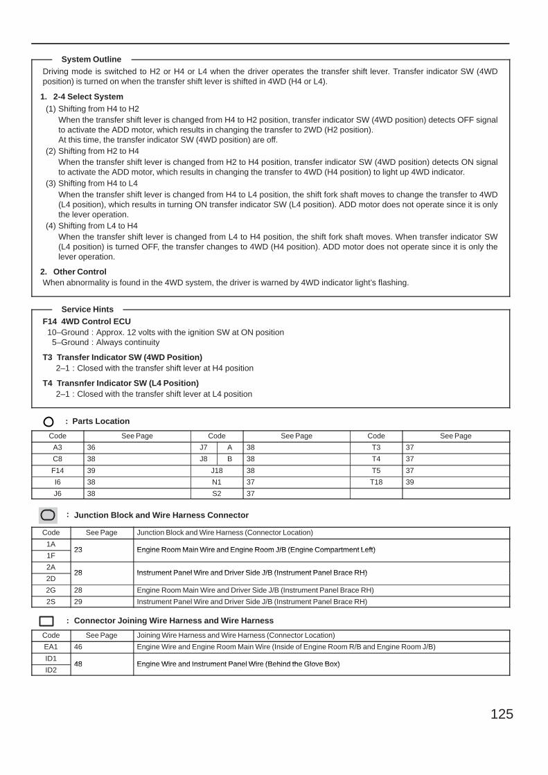
125
Driving mode is switched to H2 or H4 or L4 when the driver operates the transfer shift lever. Transfer indicator SW (4WDposition) is turned on when the transfer shift lever is shifted in 4WD (H4 or L4).
1. 2-4 Select System(1) Shifting from H4 to H2
When the transfer shift lever is changed from H4 to H2 position, transfer indicator SW (4WD position) detects OFF signalto activate the ADD motor, which results in changing the transfer to 2WD (H2 position).At this time, the transfer indicator SW (4WD position) are off.
(2) Shifting from H2 to H4When the transfer shift lever is changed from H2 to H4 position, transfer indicator SW (4WD position) detects ON signalto activate the ADD motor, which results in changing the transfer to 4WD (H4 position) to light up 4WD indicator.
(3) Shifting from H4 to L4When the transfer shift lever is changed from H4 to L4 position, the shift fork shaft moves to change the transfer to 4WD(L4 position), which results in turning ON transfer indicator SW (L4 position). ADD motor does not operate since it is onlythe lever operation.
(4) Shifting from L4 to H4When the transfer shift lever is changed from L4 to H4 position, the shift fork shaft moves. When transfer indicator SW(L4 position) is turned OFF, the transfer changes to 4WD (H4 position). ADD motor does not operate since it is only thelever operation.
2. Other ControlWhen abnormality is found in the 4WD system, the driver is warned by 4WD indicator light’s flashing.
F14 4WD Control ECU10–Ground : Approx. 12 volts with the ignition SW at ON position
5–Ground : Always continuity
T3 Transfer Indicator SW (4WD Position)2–1 : Closed with the transfer shift lever at H4 position
T4 Transnfer Indicator SW (L4 Position)2–1 : Closed with the transfer shift lever at L4 position
: Parts Location
Code See Page Code See Page Code See Page
A3 36 J7 A 38 T3 37
C8 38 J8 B 38 T4 37
F14 39 J18 38 T5 37
I6 38 N1 37 T18 39
J6 38 S2 37
: Junction Block and Wire Harness Connector
Code See Page Junction Block and Wire Harness (Connector Location)
1A23 Engine Room Main Wire and Engine Room J/B (Engine Compartment Left)
1F23 Engine Room Main Wire and Engine Room J/B (Engine Compartment Left)
2A28 Instrument Panel Wire and Driver Side J/B (Instrument Panel Brace RH)
2D28 Instrument Panel Wire and Driver Side J/B (Instrument Panel Brace RH)
2G 28 Engine Room Main Wire and Driver Side J/B (Instrument Panel Brace RH)
2S 29 Instrument Panel Wire and Driver Side J/B (Instrument Panel Brace RH)
: Connector Joining Wire Harness and Wire Harness
Code See Page Joining Wire Harness and Wire Harness (Connector Location)
EA1 46 Engine Wire and Engine Room Main Wire (Inside of Engine Room R/B and Engine Room J/B)
ID148 Engine Wire and Instrument Panel Wire (Behind the Glove Box)
ID248 Engine Wire and Instrument Panel Wire (Behind the Glove Box)
System Outline
Service Hints
126
4WD
: Ground Points
Code See Page Ground Points Location
EC 46 Rear Side of the Cylinder Block

127
Memo
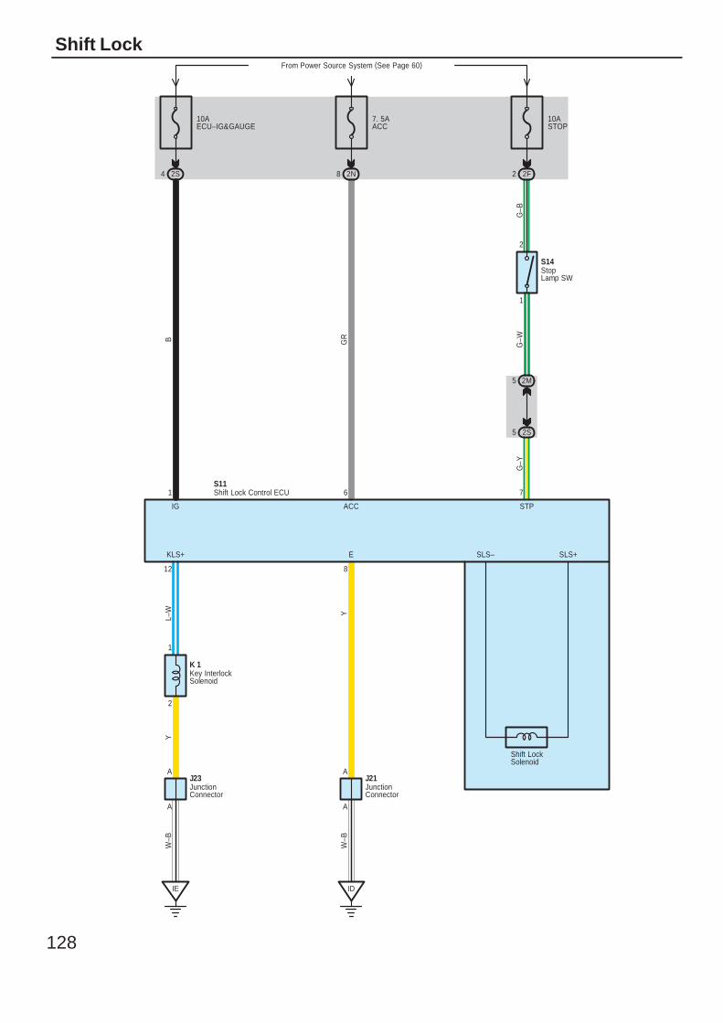
128
Shift Lock
L–W
Y
G–Y
Y
Shift LockSolenoid
5
G–B
G–W
2M
From Power Source System (See Page 60)
10ASTOP
2 2F
2
1
10AECU–IG&GAUGE
7. 5AACC
2S4 2N8
IE
A
A
A
A
ID
2S5
B GR
1 6 7
IG ACC STP
KLS+ E SLS– SLS+
12 8
1
2
S11
W–B
W–B
K 1
S14
J23 J21JunctionConnector
JunctionConnector
Key InterlockSolenoid
Shift Lock Control ECU
StopLamp SW
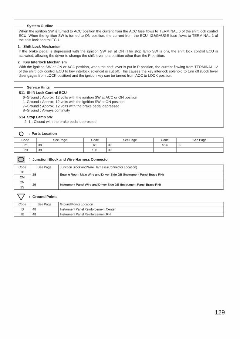
129
When the ignition SW is turned to ACC position the current from the ACC fuse flows to TERMINAL 6 of the shift lock controlECU. When the ignition SW is turned to ON position, the current from the ECU–IG&GAUGE fuse flows to TERMINAL 1 ofthe shift lock control ECU.
1. Shift Lock MechanismIf the brake pedal is depressed with the ignition SW set at ON (The stop lamp SW is on), the shift lock control ECU isactivated, allowing the driver to change the shift lever to a position other than the P position.
2. Key Interlock MechanismWith the ignition SW at ON or ACC position, when the shift lever is put in P position, the current flowing from TERMINAL 12of the shift lock control ECU to key interlock solenoid is cut off. This causes the key interlock solenoid to turn off (Lock leverdisengages from LOCK position) and the ignition key can be turned from ACC to LOCK position.
S11 Shift Lock Control ECU6–Ground : Approx. 12 volts with the ignition SW at ACC or ON position1–Ground : Approx. 12 volts with the ignition SW at ON position7–Ground : Approx. 12 volts with the brake pedal depressed8–Ground : Always continuity
S14 Stop Lamp SW2–1 : Closed with the brake pedal depressed
: Parts Location
Code See Page Code See Page Code See Page
J21 38 K1 39 S14 39
J23 38 S11 39
: Junction Block and Wire Harness Connector
Code See Page Junction Block and Wire Harness (Connector Location)
2F28 Engine Room Main Wire and Driver Side J/B (Instrument Panel Brace RH)
2M28 Engine Room Main Wire and Driver Side J/B (Instrument Panel Brace RH)
2N29 Instrument Panel Wire and Driver Side J/B (Instrument Panel Brace RH)
2S29 Instrument Panel Wire and Driver Side J/B (Instrument Panel Brace RH)
: Ground Points
Code See Page Ground Points Location
ID 48 Instrument Panel Reinforcement Center
IE 48 Instrument Panel Reinforcement RH
System Outline
Service Hints
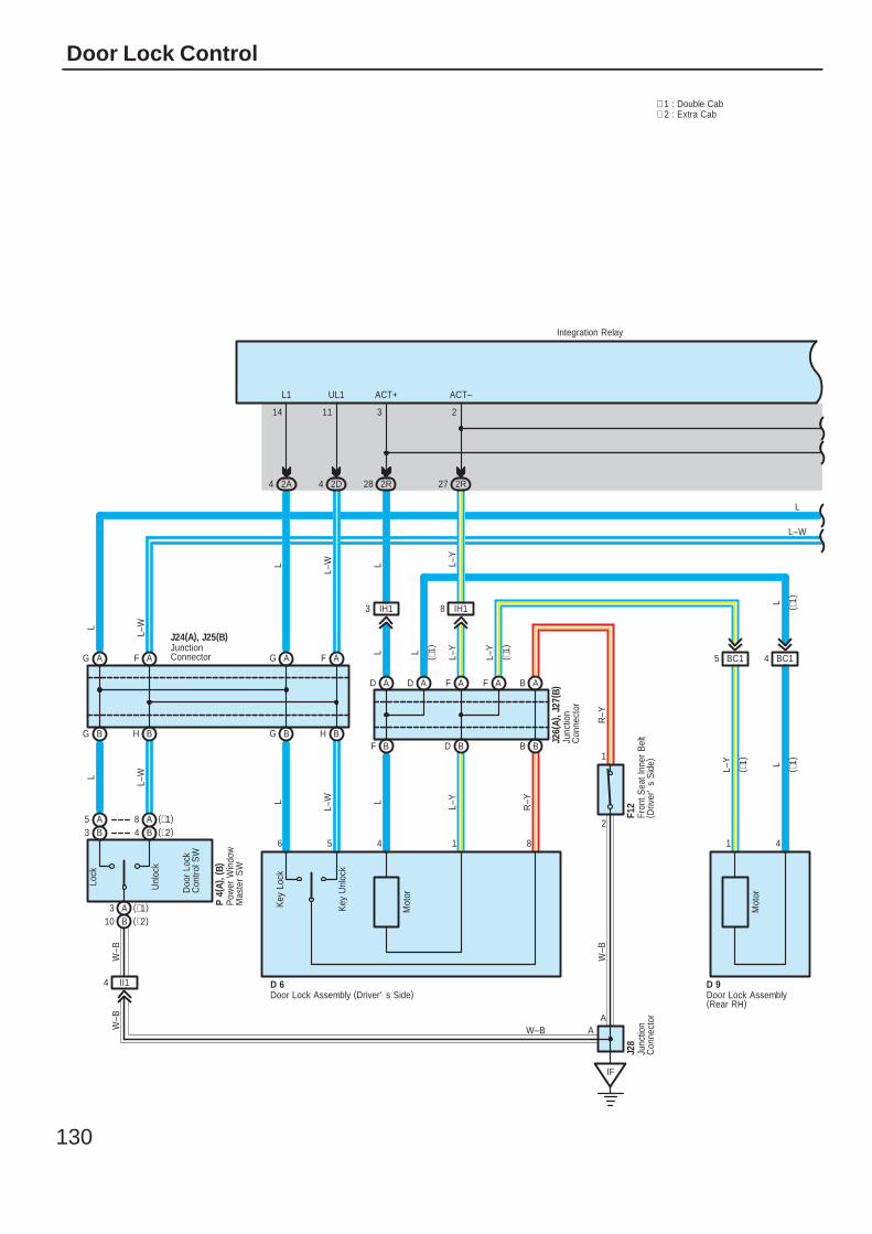
130
Door Lock Control
2A4 2D4
AG AF
BHBGBHBG
Unl
ock
Lock
IF
A
II14
2R28 2R27
BF BD
AD AFAD AF AB
BB
2
1
BC15 BC14
4181456
14 11 3 2
W–B A
ACT–ACT+UL1L1
L
L–W
L
L–W
W–B
L
L–W L L–Y
R–Y
W–B
L–Y L
R–Y
L L L–Y
L–Y
L–Y
L
L
Integration Relay
J26(
A), J
27( B
)
F12
D 9D 6
Mot
or
Mot
or
Door Lock Assembly (Driver' s Side) Door Lock Assembly(Rear RH)
Fron
t Sea
t Inn
er B
elt
( Driv
er'
s S
ide)
Junc
tion
Con
nect
or
Pow
er W
indo
wM
aste
r S
W
P 4(
A), (
B)
Doo
r Lo
ckC
ontro
l SW
B4 (∗2)A8 (∗1)
B3A5
A3 (∗1)B10 (∗2)
∗ 1 : Double Cab∗ 2 : Extra Cab
AFAG
L
L–W
L–W
L
J28
Junc
tion
Con
nect
orJunctionConnector
J24(A), J25(B)
Key
Unl
ock
Key
Loc
k
( ∗1)
( ∗1)
( ∗1)
( ∗1)
( ∗1)
W–B
IH18IH13
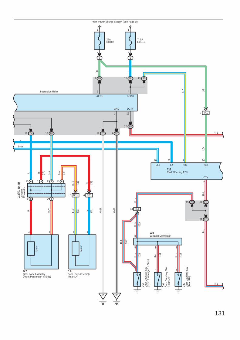
131
25ADOOR
3
2
1
7. 5AECU–B
From Power Source System (See Page 60)
1
2
1
2H4
AD AD AE AE
BE BD
2K11 2K10
14 41
BB15 BB14
ID IE
2D18 2D9
1
5
GND
ALTBLG L
R R–Y
L–Y L
R–Y R
W–B
W–B
R–Y
L–YRL
Integration Relay
Mot
or
Mot
or
D 7 D 8Door Lock Assembly(Front Passenger' s Side)
Door Lock Assembly(Rear LH)
Junc
tion
Con
nect
or
J13(
A), J
14( B
)
L–W
L
LGL–Y
UL3 L2
IH17
CTY
BB B
11 1
R–L
R–L
R–L
R–L
7
D 3
D 4
D 5
J29
31 2O
14 2N
Doo
r C
ourte
sy S
W( F
ront
Pas
seng
er'
s S
ide)
Doo
r C
ourte
sy S
W( R
ear
LH)
Doo
r C
ourte
sy S
W( R
ear
RH
)
Junction Connector
R–L
2526
( ∗1)
( ∗1)
( ∗1)
IA113
B
R–L
T16
2O15
2O27
DCTY
16
12 2L
BECU
4
2S13
+B1
4 14
+B2
R–B
R–L
LG
R–L
( ∗2)
( ∗1)
R–L
Theft Warning ECU
( ∗1)
( ∗1)
( ∗1)
( ∗1)
( ∗1)
( ∗1)
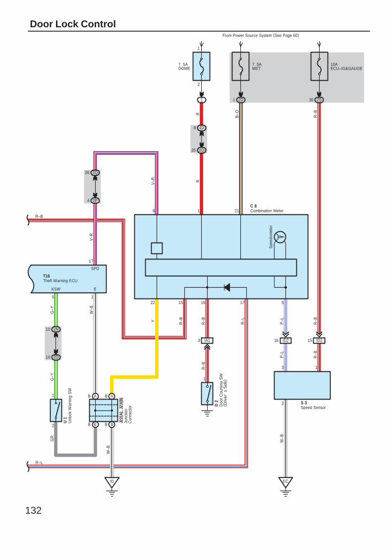
132
Door Lock Control
R–B
15
D 2
Doo
r C
ourte
sy S
W( D
river
's
Sid
e)
S 3Speed Sensor
T16
J22(
A), J
23( B
)Ju
nctio
nC
onne
ctor
10AECU–IG&GAUGE
2S30
2Q
R–L
8 2J
7. 5ADOME
1
2
1
ID
BB
AB AB
BB
W–B
V–R
W–B
1
E
2Q25
SPD
17
GR
4
26
G–Y
G–Y
KSW
10 2O
10 2N
5
1
2
R
Unl
ock
War
ning
SW
U 1
1 2D
7. 5AMET
Y
B–O
C 8
From Power Source System (See Page 60)
Spe
edom
eter
R–B
3
2
P–L
W–B
1
P–L
R–B
EC
ID216 ID215
1 21
22 5
R
Combination Meter
16
R–B
1
R–B
IA13
17
R–L
R–B
2P
6
R–B
V–R
Theft Warning ECU
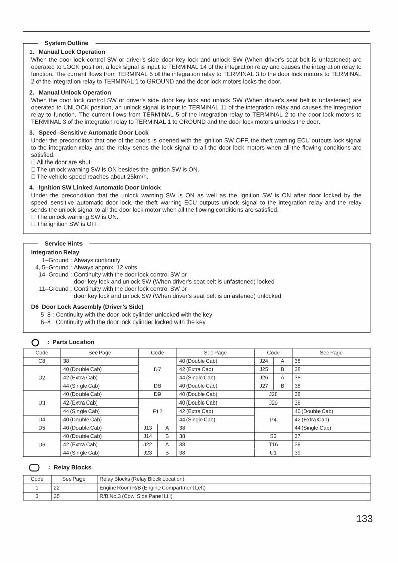
133
1. Manual Lock OperationWhen the door lock control SW or driver’s side door key lock and unlock SW (When driver’s seat belt is unfastened) areoperated to LOCK position, a lock signal is input to TERMINAL 14 of the integration relay and causes the integration relay tofunction. The current flows from TERMINAL 5 of the integration relay to TERMINAL 3 to the door lock motors to TERMINAL2 of the integration relay to TERMINAL 1 to GROUND and the door lock motors locks the door.
2. Manual Unlock OperationWhen the door lock control SW or driver’s side door key lock and unlock SW (When driver’s seat belt is unfastened) areoperated to UNLOCK position, an unlock signal is input to TERMINAL 11 of the integration relay and causes the integrationrelay to function. The current flows from TERMINAL 5 of the integration relay to TERMINAL 2 to the door lock motors toTERMINAL 3 of the integration relay to TERMINAL 1 to GROUND and the door lock motors unlocks the door.
3. Speed–Sensitive Automatic Door LockUnder the precondition that one of the doors is opened with the ignition SW OFF, the theft warning ECU outputs lock signalto the integration relay and the relay sends the lock signal to all the door lock motors when all the flowing conditions aresatisfied.∗ All the door are shut.∗ The unlock warning SW is ON besides the ignition SW is ON.∗ The vehicle speed reaches about 25km/h.
4. Ignition SW Linked Automatic Door UnlockUnder the precondition that the unlock warning SW is ON as well as the ignition SW is ON after door locked by thespeed–sensitive automatic door lock, the theft warning ECU outputs unlock signal to the integration relay and the relaysends the unlock signal to all the door lock motor when all the flowing conditions are satisfied.∗ The unlock warning SW is ON.∗ The ignition SW is OFF.
Integration Relay1–Ground : Always continuity
4, 5–Ground : Always approx. 12 volts14–Ground : Continuity with the door lock control SW or
door key lock and unlock SW (When driver’s seat belt is unfastened) locked11–Ground : Continuity with the door lock control SW or
door key lock and unlock SW (When driver’s seat belt is unfastened) unlocked
D6 Door Lock Assembly (Driver’s Side)5–8 : Continuity with the door lock cylinder unlocked with the key6–8 : Continuity with the door lock cylinder locked with the key
: Parts Location
Code See Page Code See Page Code See Page
C8 38
D7
40 (Double Cab) J24 A 38
D2
40 (Double Cab) D7 42 (Extra Cab) J25 B 38
D2 42 (Extra Cab)
D7
44 (Single Cab) J26 A 38D2
44 (Single Cab) D8 40 (Double Cab) J27 B 38
D3
40 (Double Cab) D9 40 (Double Cab) J28 38
D3 42 (Extra Cab)
F12
40 (Double Cab) J29 38D3
44 (Single Cab) F12 42 (Extra Cab)
P4
40 (Double Cab)
D4 40 (Double Cab)
F12
44 (Single Cab) P4 42 (Extra Cab)
D5 40 (Double Cab) J13 A 38
P4
44 (Single Cab)
D6
40 (Double Cab) J14 B 38 S3 37
D6 42 (Extra Cab) J22 A 38 T16 39D6
44 (Single Cab) J23 B 38 U1 39
: Relay Blocks
Code See Page Relay Blocks (Relay Block Location)
1 22 Engine Room R/B (Engine Compartment Left)
3 35 R/B No.3 (Cowl Side Panel LH)
System Outline
Service Hints
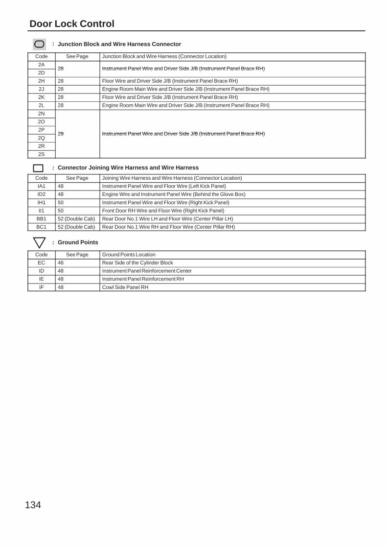
134
Door Lock Control
: Junction Block and Wire Harness Connector
Code See Page Junction Block and Wire Harness (Connector Location)
2A28 Instrument Panel Wire and Driver Side J/B (Instrument Panel Brace RH)
2D28 Instrument Panel Wire and Driver Side J/B (Instrument Panel Brace RH)
2H 28 Floor Wire and Driver Side J/B (Instrument Panel Brace RH)
2J 28 Engine Room Main Wire and Driver Side J/B (Instrument Panel Brace RH)
2K 28 Floor Wire and Driver Side J/B (Instrument Panel Brace RH)
2L 28 Engine Room Main Wire and Driver Side J/B (Instrument Panel Brace RH)
2N
29 Instrument Panel Wire and Driver Side J/B (Instrument Panel Brace RH)
2O
29 Instrument Panel Wire and Driver Side J/B (Instrument Panel Brace RH)2P
29 Instrument Panel Wire and Driver Side J/B (Instrument Panel Brace RH)2Q
29 Instrument Panel Wire and Driver Side J/B (Instrument Panel Brace RH)
2R
2S
: Connector Joining Wire Harness and Wire Harness
Code See Page Joining Wire Harness and Wire Harness (Connector Location)
IA1 48 Instrument Panel Wire and Floor Wire (Left Kick Panel)
ID2 48 Engine Wire and Instrument Panel Wire (Behind the Glove Box)
IH1 50 Instrument Panel Wire and Floor Wire (Right Kick Panel)
II1 50 Front Door RH Wire and Floor Wire (Right Kick Panel)
BB1 52 (Double Cab) Rear Door No.1 Wire LH and Floor Wire (Center Pillar LH)
BC1 52 (Double Cab) Rear Door No.1 Wire RH and Floor Wire (Center Pillar RH)
: Ground Points
Code See Page Ground Points Location
EC 46 Rear Side of the Cylinder Block
ID 48 Instrument Panel Reinforcement Center
IE 48 Instrument Panel Reinforcement RH
IF 48 Cowl Side Panel RH

135
Memo
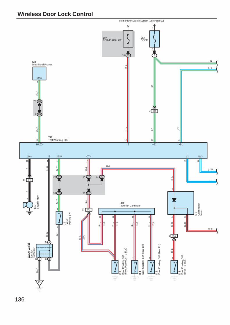
136
Wireless Door Lock ControlFrom Power Source System (See Page 60)
LGLG
1
IF313
13
SH–
BB
25ADOOR
IH17
+B2
14
B
IA1
B
13
B
11 1
R–L
R–L
R–L
R–L
D 3
D 4
D 5
J29
IG
18
R–L
3
1
2
5
2N10
2O10
KSW
G–Y
G–Y
2
1
GR
2N14
2O15
R–L
B
R–L
CTY
7
T16
Doo
r C
ourte
sy S
W( F
ront
Pas
seng
er'
s S
ide)
Doo
r C
ourte
sy S
W (
Rea
r LH
)
Doo
r C
ourte
sy S
W (
Rea
r R
H)
Junction Connector
( ∗1)
( ∗1)
( ∗1)
( ∗1)
R–L
( ∗2)
S 1
L2
25
UL3
26
L–W
L
BB
AB
2O25
2N9
HAZD
28
8
EHW
G–O
G–O
Turn Signal FlasherT22
2O31
IA13
1
D 2
Doo
r C
ourte
sy S
W( D
river
's
Sid
e)
16 15
17
R–L
R–L
R–B
R–B
Com
bina
tion
Met
er
C 8
R–B
R–B
L–Y
L–Y
+B1
4
Junc
tion
Con
nect
or
J22(
A), J
23( B
)
Unl
ock
War
ning
SW
U 1
B–W
E
1
B–W
W–B
ID
LG
10AECU–IG&GAUGE
2S16
R–L
Sec
urity
Hor
n
Theft Warning ECU
BB
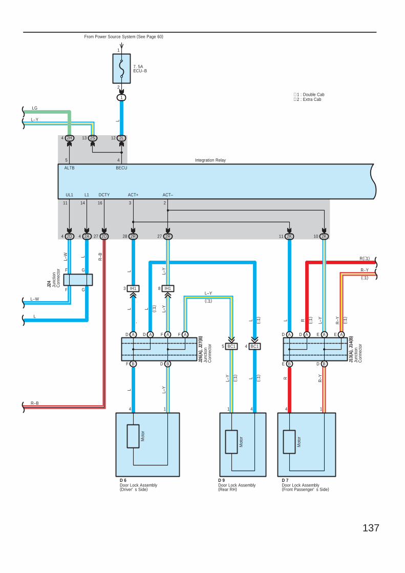
137
∗ 2 : Extra Cab∗ 1 : Double Cab
F G
F G
7. 5AECU–B
From Power Source System (See Page 60)
1
D 9
2
1
2L12
4 2D 2A4 2R28 2R27
L
BF
R
BD
L–Y
ADR
–YAFAD AF
R–Y
D 7
BC15
R
BC14
41
Integration Relay
L
14
L–Y
L–Y
AD
LL
AD
LL–Y
AE
L–Y
AE
L
BE BD
BECU
2K11
L
UL1
2K10
1
L1
4
ACT+ ACT–
Mot
or
4
Mot
or
2
Mot
or
31411
Door Lock Assembly(Front Passenger' s Side)
Door Lock Assembly(Rear RH)
Door Lock Assembly(Driver' s Side)
D 6
Junc
tion
Con
nect
or
J26(
A), J
27( B
)
L
Junc
tion
Con
nect
or
J13(
A), J
14( B
)
L–W
L
L
L–W
R(∗1)
R–Y
Junc
tion
Con
nect
or
J24
2O27
R–B
R–B
16
DCTY
2S13
L–Y
2H4
5
ALTB
LG
( ∗1)
( ∗1)
( ∗1)
( ∗1)
( ∗1)
( ∗1)
(∗1)
IH18IH13L–Y
(∗1)
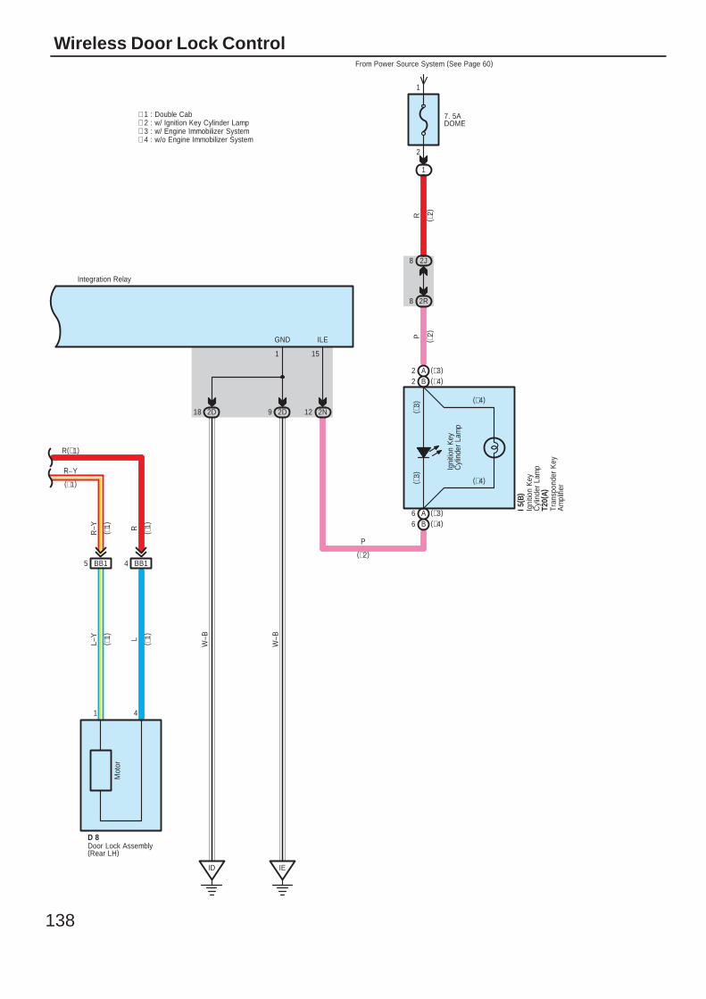
138
Wireless Door Lock Control
R–Y
R(∗1)
Door Lock Assembly(Rear LH)
9 2D18 2D
IEID
1
4 BB15 BB1
1 4
GND
D 8
Mot
or
L–Y L
R–Y R
W–B
W–B
Integration Relay
7. 5ADOME
From Power Source System (See Page 60)
1
2
1
2R8
2J8
2N12
15
ILE
R
P
P
Igni
tion
Key
Cyl
inde
r La
mp
I 5( B
)
( ∗1)
( ∗1)
( ∗1)
( ∗1)
(∗1)
B2 (∗4)A2 (∗3)
A6 (∗3)B6 (∗4)
(∗4)
(∗4)( ∗3)
( ∗3)
T20(
A)Tr
ansp
onde
r K
eyA
mpl
ifier
(∗2)
( ∗2)
( ∗2)
∗ 2 : w/ Ignition Key Cylinder Lamp∗ 1 : Double Cab
∗ 3 : w/ Engine Immobilizer System∗ 4 : w/o Engine Immobilizer System
Igni
tion
Key
Cyl
inde
r La
mp
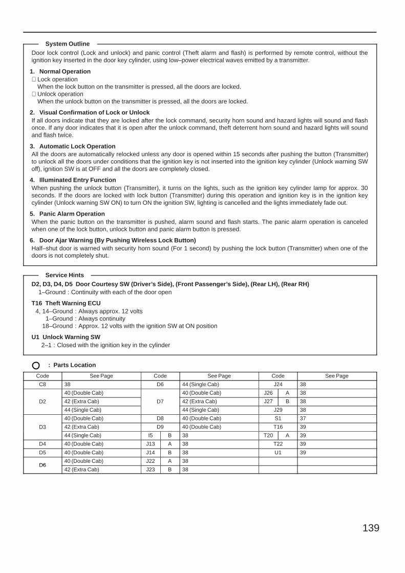
139
Door lock control (Lock and unlock) and panic control (Theft alarm and flash) is performed by remote control, without theignition key inserted in the door key cylinder, using low–power electrical waves emitted by a transmitter.
1. Normal Operation∗ Lock operation
When the lock button on the transmitter is pressed, all the doors are locked.∗ Unlock operation
When the unlock button on the transmitter is pressed, all the doors are locked.
2. Visual Confirmation of Lock or UnlockIf all doors indicate that they are locked after the lock command, security horn sound and hazard lights will sound and flashonce. If any door indicates that it is open after the unlock command, theft deterrent horn sound and hazard lights will soundand flash twice.
3. Automatic Lock OperationAll the doors are automatically relocked unless any door is opened within 15 seconds after pushing the button (Transmitter)to unlock all the doors under conditions that the ignition key is not inserted into the ignition key cylinder (Unlock warning SWoff), ignition SW is at OFF and all the doors are completely closed.
4. Illuminated Entry FunctionWhen pushing the unlock button (Transmitter), it turns on the lights, such as the ignition key cylinder lamp for approx. 30seconds. If the doors are locked with lock button (Transmitter) during this operation and ignition key is in the ignition keycylinder (Unlock warning SW ON) to turn ON the ignition SW, lighting is cancelled and the lights immediately fade out.
5. Panic Alarm OperationWhen the panic button on the transmitter is pushed, alarm sound and flash starts. The panic alarm operation is canceledwhen one of the lock button, unlock button and panic alarm button is pressed.
6. Door Ajar Warning (By Pushing Wireless Lock Button)Half–shut door is warned with security horn sound (For 1 second) by pushing the lock button (Transmitter) when one of thedoors is not completely shut.
D2, D3, D4, D5 Door Courtesy SW (Driver’s Side), (Front Passenger’s Side), (Rear LH), (Rear RH)1–Ground : Continuity with each of the door open
T16 Theft Warning ECU4, 14–Ground : Always approx. 12 volts
1–Ground : Always continuity18–Ground : Approx. 12 volts with the ignition SW at ON position
U1 Unlock Warning SW2–1 : Closed with the ignition key in the cylinder
: Parts Location
Code See Page Code See Page Code See Page
C8 38 D6 44 (Single Cab) J24 38
D2
40 (Double Cab)
D7
40 (Double Cab) J26 A 38
D2 42 (Extra Cab) D7 42 (Extra Cab) J27 B 38D2
44 (Single Cab)
D7
44 (Single Cab) J29 38
D3
40 (Double Cab) D8 40 (Double Cab) S1 37
D3 42 (Extra Cab) D9 40 (Double Cab) T16 39D3
44 (Single Cab) I5 B 38 T20 A 39
D4 40 (Double Cab) J13 A 38 T22 39
D5 40 (Double Cab) J14 B 38 U1 39
D640 (Double Cab) J22 A 38
D642 (Extra Cab) J23 B 38
System Outline
Service Hints
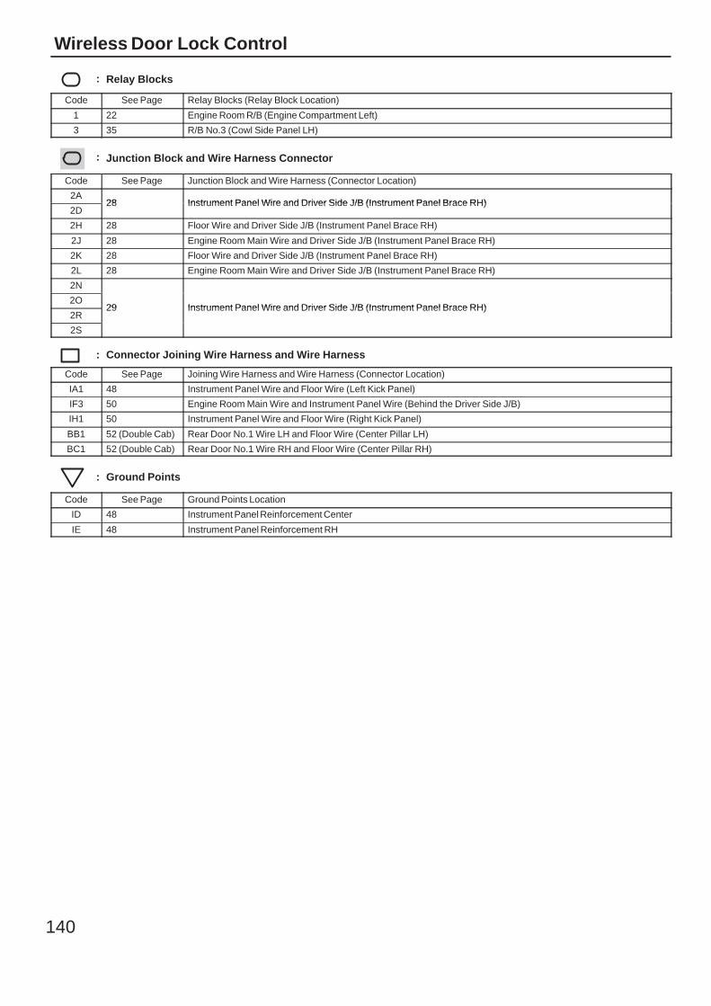
140
Wireless Door Lock Control
: Relay Blocks
Code See Page Relay Blocks (Relay Block Location)
1 22 Engine Room R/B (Engine Compartment Left)
3 35 R/B No.3 (Cowl Side Panel LH)
: Junction Block and Wire Harness Connector
Code See Page Junction Block and Wire Harness (Connector Location)
2A28 Instrument Panel Wire and Driver Side J/B (Instrument Panel Brace RH)
2D28 Instrument Panel Wire and Driver Side J/B (Instrument Panel Brace RH)
2H 28 Floor Wire and Driver Side J/B (Instrument Panel Brace RH)
2J 28 Engine Room Main Wire and Driver Side J/B (Instrument Panel Brace RH)
2K 28 Floor Wire and Driver Side J/B (Instrument Panel Brace RH)
2L 28 Engine Room Main Wire and Driver Side J/B (Instrument Panel Brace RH)
2N
29 Instrument Panel Wire and Driver Side J/B (Instrument Panel Brace RH)2O
29 Instrument Panel Wire and Driver Side J/B (Instrument Panel Brace RH)2R
29 Instrument Panel Wire and Driver Side J/B (Instrument Panel Brace RH)
2S
: Connector Joining Wire Harness and Wire Harness
Code See Page Joining Wire Harness and Wire Harness (Connector Location)
IA1 48 Instrument Panel Wire and Floor Wire (Left Kick Panel)
IF3 50 Engine Room Main Wire and Instrument Panel Wire (Behind the Driver Side J/B)
IH1 50 Instrument Panel Wire and Floor Wire (Right Kick Panel)
BB1 52 (Double Cab) Rear Door No.1 Wire LH and Floor Wire (Center Pillar LH)
BC1 52 (Double Cab) Rear Door No.1 Wire RH and Floor Wire (Center Pillar RH)
: Ground Points
Code See Page Ground Points Location
ID 48 Instrument Panel Reinforcement Center
IE 48 Instrument Panel Reinforcement RH

141
Memo
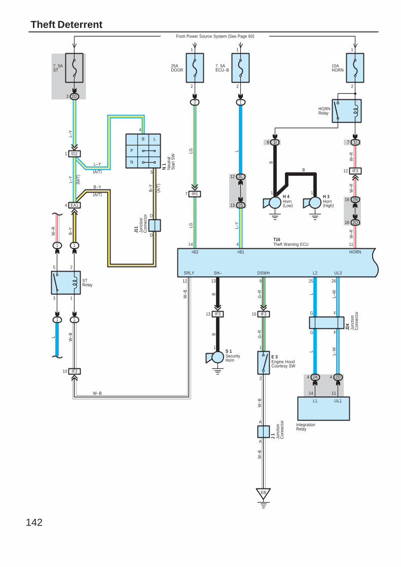
142
Theft DeterrentFrom Power Source System (See Page 60)
LLG
L–Y
LG
1
IF315
A
A
2
1
EB
9
DSWH
E 3
G–R
G–R
W–B
W–B
IF313
S 1
13
SH–
BB
L2
25 26
UL3
L
L–W
10AHORN
2
1
HORNRelay
1I71I
IF312
1 1
2O16
2N16
W–R
B
W–R
B
H 4 H 3
W–R
25ADOOR
7. 5AECU–B
2
1
2S13
2L12
IH17
+B2 +B1
14 4
8
SRLY
12
EA1
ID2
IF3
1( A
/T)
STRelay
5
4
P
N
1
2
3
5
B–Y
B–Y
L–Y
L
L–Y
( M/T
)
W–R
7. 5AST
4
10
(A/T)
B–Y
(A/T)
L–Y
B L
2O3
1 1
1 1
W–B
J11
W–B
W–B
3 1
1
2
HORN
11
J24
T16
Engine HoodCourtesy SW
Horn(High)
Horn(Low)
Junc
tion
Con
nect
or
Junc
tion
Con
nect
or
D
D
Neu
tral
Sta
rt S
W
N 1
SecurityHorn
Theft Warning ECU
G F
G F
2A4 2D4
L
L–W
L1
14 11
UL1
J 1
Junc
tion
Con
nect
or IntegrationRelay
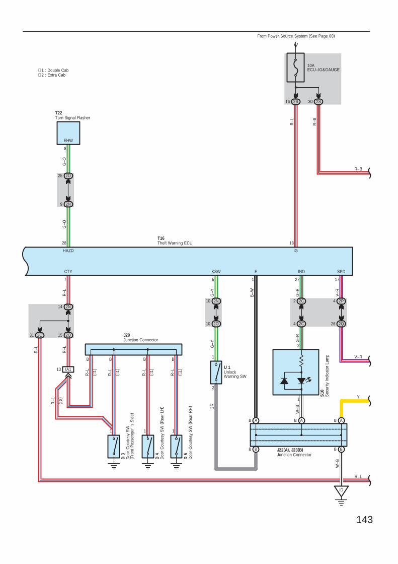
143
10AECU–IG&GAUGE
2S16
ID
∗ 2 : Extra Cab∗ 1 : Double Cab
BB
AB AB
2S30
B–W
2
1
2C2
2C4
AB
27
IND
G–R
G–R
1
E
W–B
W–B
HAZD
28
2N9
2O25
EHW
T22
G–O
G–O
8
B
IA1
B
13
B
11 1
R–L
R–L
R–L
R–L
D 3
D 4
D 5
J29
IG
18
BB
SPD
R–L
R–B
V–R
2Q26
2P4
175
2N10
2O10
KSW
G–Y
G–Y
2
1
GR
2N14
2O15
R–L
B
R–L
CTY
7
J22(A), J23(B)
T16
From Power Source System (See Page 60)
R–B
V–R
Y
Doo
r C
ourte
sy S
W( F
ront
Pas
seng
er'
s S
ide)
Doo
r C
ourte
sy S
W (
Rea
r LH
)
Doo
r C
ourte
sy S
W (
Rea
r R
H)
Junction Connector
Junction Connector
Turn Signal Flasher
UnlockWarning SW
U 1
( ∗1)
( ∗1)
( ∗1)
( ∗1)
R–L
( ∗2)
S10
2O31
R–L
R–L
Theft Warning ECU
Sec
urity
Indi
cato
r La
mp
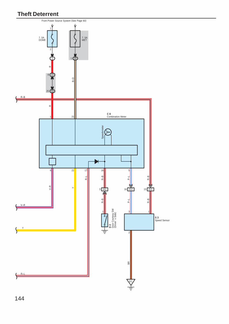
144
Theft Deterrent
8 2J
7. 5ADOME
1
2
1
RR
D 2
Doo
r C
ourte
sy S
W( D
river
's
Sid
e)
16
R–B
R–B
1
3 IA1
25 2Q
1 2D
7. 5AMET
YB
–O
V–R
C 8
From Power Source System (See Page 60)
Spe
edom
eter
R–B
3
2
P–L
BR
1
P–L
R–B
EC
ID216 ID215
1 21
22 56
S 3
R–B
V–R
Y
Combination Meter
Speed Sensor
17
R–L
R–L
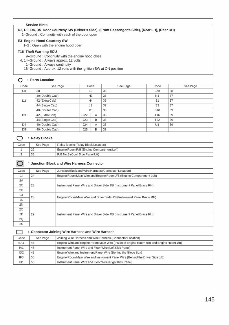
145
D2, D3, D4, D5 Door Courtesy SW (Driver’s Side), (Front Passenger’s Side), (Rear LH), (Rear RH)1–Ground : Continuity with each of the door open
E3 Engine Hood Courtesy SW1–2 : Open with the engine hood open
T16 Theft Warning ECU9–Ground : Continuity with the engine hood close
4, 14–Ground : Always approx. 12 volts1–Ground : Always continuity
18–Ground : Approx. 12 volts with the ignition SW at ON position
: Parts Location
Code See Page Code See Page Code See Page
C8 38 E3 36 J29 38
D2
40 (Double Cab) H3 36 N1 37
D2 42 (Extra Cab) H4 36 S1 37D2
44 (Single Cab) J1 37 S3 37
D3
40 (Double Cab) J11 38 S10 39
D3 42 (Extra Cab) J22 A 38 T16 39D3
44 (Single Cab) J23 B 38 T22 39
D4 40 (Double Cab) J24 A 38 U1 39
D5 40 (Double Cab) J25 B 38
: Relay Blocks
Code See Page Relay Blocks (Relay Block Location)
1 22 Engine Room R/B (Engine Compartment Left)
3 35 R/B No.3 (Cowl Side Panel LH)
: Junction Block and Wire Harness Connector
Code See Page Junction Block and Wire Harness (Connector Location)
1I 24 Engine Room Main Wire and Engine Room J/B (Engine Compartment Left)
2A
28 Instrument Panel Wire and Driver Side J/B (Instrument Panel Brace RH)2C 28 Instrument Panel Wire and Driver Side J/B (Instrument Panel Brace RH)
2D
28 Instrument Panel Wire and Driver Side J/B (Instrument Panel Brace RH)
2J28 Engine Room Main Wire and Driver Side J/B (Instrument Panel Brace RH)
2L28 Engine Room Main Wire and Driver Side J/B (Instrument Panel Brace RH)
2N
29 Instrument Panel Wire and Driver Side J/B (Instrument Panel Brace RH)
2O
29 Instrument Panel Wire and Driver Side J/B (Instrument Panel Brace RH)2P 29 Instrument Panel Wire and Driver Side J/B (Instrument Panel Brace RH)
2Q
29 Instrument Panel Wire and Driver Side J/B (Instrument Panel Brace RH)
2S
: Connector Joining Wire Harness and Wire Harness
Code See Page Joining Wire Harness and Wire Harness (Connector Location)
EA1 46 Engine Wire and Engine Room Main Wire (Inside of Engine Room R/B and Engine Room J/B)
IA1 48 Instrument Panel Wire and Floor Wire (Left Kick Panel)
ID2 48 Engine Wire and Instrument Panel Wire (Behind the Glove Box)
IF3 50 Engine Room Main Wire and Instrument Panel Wire (Behind the Driver Side J/B)
IH1 50 Instrument Panel Wire and Floor Wire (Right Kick Panel)
Service Hints
146
Theft Deterrent
: Ground Points
Code See Page Ground Points Location
EB 46 Left Side of the Fender Apron
EC 46 Rear Side of the Cylinder Block
ID 48 Instrument Panel Reinforcement Center

147
Memo
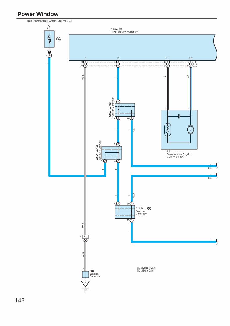
148
Power Window
30APWR
From Power Source System (See Page 60)
3
12
BC
BC
AA
AA AA
BC
AA AA
AA
M
L
L B L–R
IF
II14
W–B
W–B
A
W–B
LL
L L
L
DDDUBE
1
2
J26(
A), J
27( B
)
J16(
A), J
17( B
)
J13(A), J14(B)
LL
P 6
L
L
L
P 4(A), (B)
J28
JunctionConnector
Junc
tion
Con
nect
or
Junc
tion
Con
nect
or
JunctionConnector
Power Window Master SW
Power Window RegulatorMotor (Front RH)
A9 (∗1)B5 (∗2)
A4B2
A6B9
A3B10
∗ 2 : Extra Cab∗ 1 : Double Cab
(∗1)
(∗1)
( ∗1)
( ∗1)
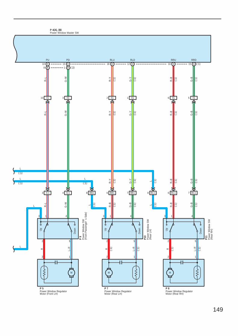
149
3 1 4 3 1 4 3 1 4
2 5 2 5 2 5
II15II16II11II12II13II110
BC17BC16BC18BB17BB16BB18IC14IC13
P 9
P10
P11
R L–R R L–R R L–R
G–B
R–BL
G–B
R–B
G–WR–L
Dow
n
Up
Dow
n
Up
Dow
n
Up
G–B
R–B
G–Y
R–Y
G–WR–L
R–L
G–W R–Y
G–Y
R–B
G–B
P 5
2 1
M
P 7
2 1
M
P 8
2 1
M
R–Y
G–Y L
R–B
G–B
RRDRRURLDRLUPDPU
L
L L
L
L
P 4(A), (B)Power Window Master SW
Power Window RegulatorMotor (Front LH)
Power Window RegulatorMotor (Rear LH)
Power Window RegulatorMotor (Rear RH)
Pow
er W
indo
w S
W( F
ront
Pas
seng
er'
s S
ide)
Pow
er W
indo
w S
W( R
ear
LH)
Pow
er W
indo
w S
W( R
ear
RH
)
L
A15 (∗1)A16A12A18A13B1 (∗2)
A10B8
( ∗1)
( ∗1)
( ∗1)
( ∗1)
( ∗1)
( ∗1)
( ∗1)
( ∗1)
( ∗1)
( ∗1)
( ∗1)
( ∗1)
( ∗1)
( ∗1)
( ∗1)
( ∗1)
( ∗1)
( ∗1)
( ∗1)
( ∗1)
( ∗1)
( ∗1)
( ∗1)
(∗1)(∗1)
(∗1)
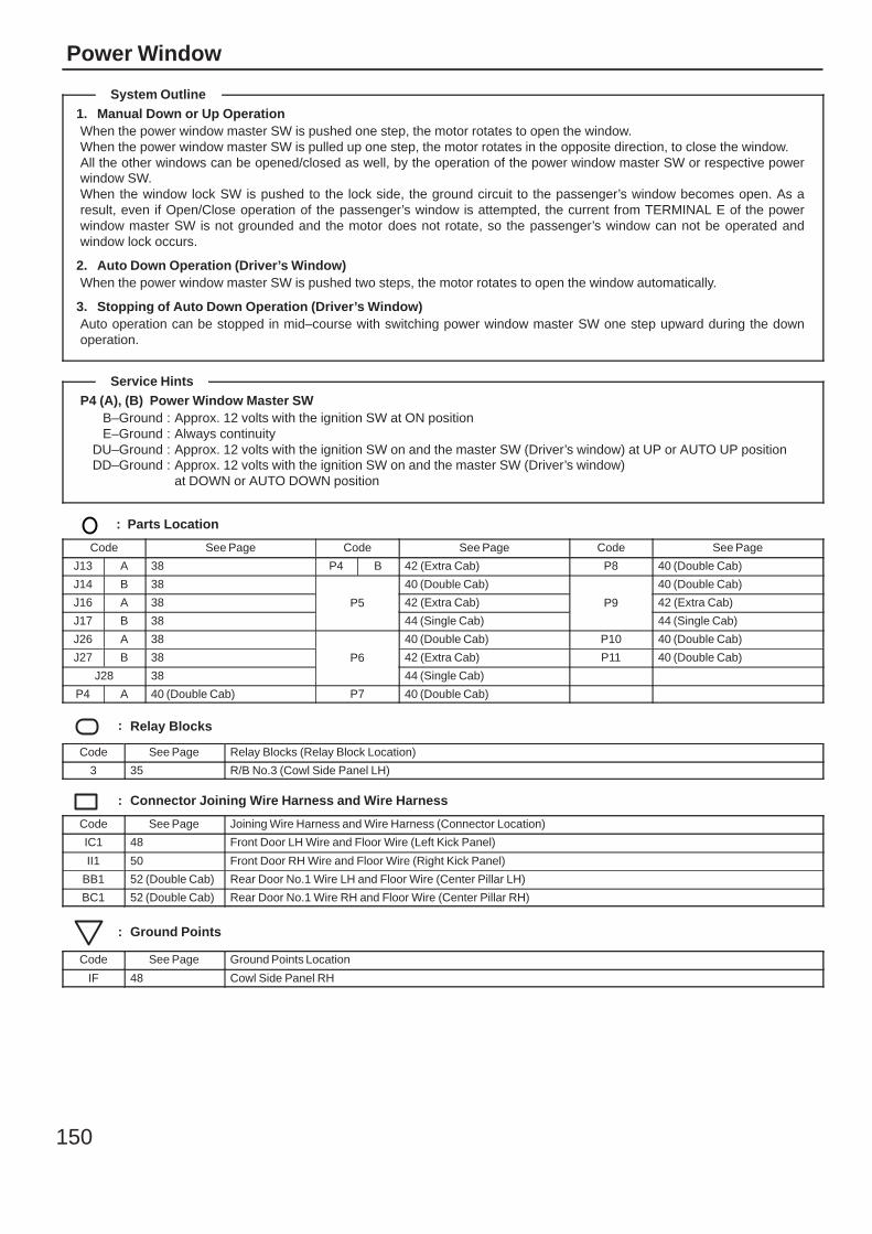
150
Power Window
1. Manual Down or Up OperationWhen the power window master SW is pushed one step, the motor rotates to open the window.When the power window master SW is pulled up one step, the motor rotates in the opposite direction, to close the window.All the other windows can be opened/closed as well, by the operation of the power window master SW or respective powerwindow SW.When the window lock SW is pushed to the lock side, the ground circuit to the passenger’s window becomes open. As aresult, even if Open/Close operation of the passenger’s window is attempted, the current from TERMINAL E of the powerwindow master SW is not grounded and the motor does not rotate, so the passenger’s window can not be operated andwindow lock occurs.
2. Auto Down Operation (Driver’s Window)When the power window master SW is pushed two steps, the motor rotates to open the window automatically.
3. Stopping of Auto Down Operation (Driver’s Window)Auto operation can be stopped in mid–course with switching power window master SW one step upward during the downoperation.
P4 (A), (B) Power Window Master SWB–Ground : Approx. 12 volts with the ignition SW at ON positionE–Ground : Always continuity
DU–Ground : Approx. 12 volts with the ignition SW on and the master SW (Driver’s window) at UP or AUTO UP positionDD–Ground : Approx. 12 volts with the ignition SW on and the master SW (Driver’s window)
at DOWN or AUTO DOWN position
: Parts Location
Code See Page Code See Page Code See Page
J13 A 38 P4 B 42 (Extra Cab) P8 40 (Double Cab)
J14 B 38
P5
40 (Double Cab)
P9
40 (Double Cab)
J16 A 38 P5 42 (Extra Cab) P9 42 (Extra Cab)
J17 B 38
P5
44 (Single Cab)
P9
44 (Single Cab)
J26 A 38
P6
40 (Double Cab) P10 40 (Double Cab)
J27 B 38 P6 42 (Extra Cab) P11 40 (Double Cab)
J28 38
P6
44 (Single Cab)
P4 A 40 (Double Cab) P7 40 (Double Cab)
: Relay Blocks
Code See Page Relay Blocks (Relay Block Location)
3 35 R/B No.3 (Cowl Side Panel LH)
: Connector Joining Wire Harness and Wire Harness
Code See Page Joining Wire Harness and Wire Harness (Connector Location)
IC1 48 Front Door LH Wire and Floor Wire (Left Kick Panel)
II1 50 Front Door RH Wire and Floor Wire (Right Kick Panel)
BB1 52 (Double Cab) Rear Door No.1 Wire LH and Floor Wire (Center Pillar LH)
BC1 52 (Double Cab) Rear Door No.1 Wire RH and Floor Wire (Center Pillar RH)
: Ground Points
Code See Page Ground Points Location
IF 48 Cowl Side Panel RH
System Outline
Service Hints

151
Memo
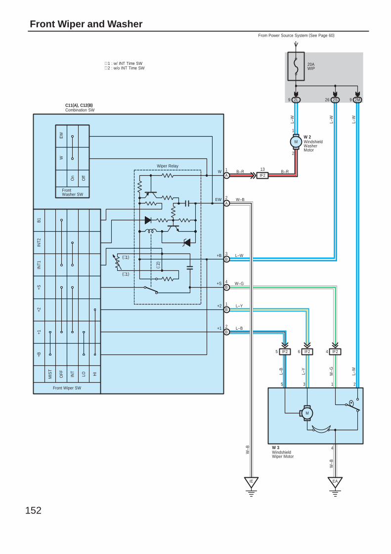
152
Front Wiper and Washer
2135
4
M
2S262L9
IE
W–B
L–W
L–W
W–B
W–G
B–R
L–B
L–Y
EA
W–B
A1
A2
B4
B1
B2
B3
2M9
L–W
W 3
MIS
T
Off
On
HI
LOINT
OFF
C11(A), C12(B)
+1+2
+SIN
T1IN
T2B
1+B
W
Front Wiper SW
FrontWasher SW
EW
W
EW
+B
+S
+2
+1
L–B
L–Y
W–G
L–W
IF25 IF26 IF24
M
2
1
L–W
W 2
IF213
∗ 1 : w/ INT Time SW
(∗1)
(∗1)
( ∗2)
∗ 2 : w/o INT Time SW
WindshieldWasherMotor
WindshieldWiper Motor
Combination SW
Wiper RelayB–R
20AWIP
From Power Source System (See Page 60)
153
With the ignition SW turned on, the current flows to TERMINAL (B) 3 of the front wiper and washer SW, TERMINAL 1 of thewindshield washer motor and TERMINAL 2 of the windshield wiper motor through the WIP fuse.
1. Low Speed PositionWith the front wiper SW turned to LO position, the current flows from TERMINAL (B) 3 of the front wiper and washer SW toTERMINAL (B) 2 to TERMINAL 5 of the windshield wiper motor to TERMINAL 4 to GROUND and causes the windshieldwiper motor to run at low speed.
2. High Speed PositionWith the front wiper SW turned to HI position, the current flows from TERMINAL (B) 3 of the front wiper and washer SW toTERMINAL (B) 1 to TERMINAL 3 of the windshield wiper motor to TERMINAL 4 to GROUND and causes the windshieldwiper motor to run at high speed.
3. INT PositionWith the front wiper SW turned to INT position, the wiper relay operates and current flows from TERMINAL (B) 3 of the frontwiper and washer SW to TERMINAL (A) 2 to GROUND. This activates the intermittent circuit and the current flows fromTERMINAL (B) 3 of the front wiper and washer SW to TERMINAL (B) 2 to TERMINAL 5 of the windshield wiper motor toTERMINAL 4 to GROUND and the wiper operates.The intermittent operation is controlled by the charge/discharge function of the condenser installed in the relay, and theintermittent time is controlled by a time control SW to change the charging time of the condenser (w/ INT time SW).Intermittent operation is controlled by a condenser charge and discharge function in the relay (w/o INT time SW).
4. Mist PositionWith the front wiper SW turned to MIST position, the current flows from TERMINAL (B) 3 of the front wiper and washer SW toTERMINAL (B) 2 to TERMINAL 5 of the windshield wiper motor to TERMINAL 4 to GROUND and causes the windshieldwiper motor to run at low speed.
5. Washer Interlocking OperationWith the washer SW pulled to ON position, the current flows from the WIP fuse to TERMINAL 1 of the windshield washermotor to TERMINAL 2 to TERMINAL (A) 1 of the front wiper and washer SW to TERMINAL (A) 2 to GROUND and causesthe windshield washer motor to run and the window washer to spray. Simultaneously, current flows from the WIP fuse toTERMINAL (B) 3 of the front wiper and washer SW to TERMINAL (B) 2 to TERMINAL 5 of the windshield wiper motor toTERMINAL 4 to GROUND, causing the wiper to function.
C11 (A), C12 (B) Combination SW(A) 2–Ground : Always continuity(B) 3–Ground : Approx. 12 volts with the ignition SW at ON position(B) 2–Ground : Approx. 12 volts with the ignition SW on and the front wiper SW at LO or MIST position
Approx. 12 volts intermittently with the ignition SW on and the front wiper SW at INT position(B) 4–Ground : Approx. 12 volts with the ignition SW on and unless the windshield wiper motor at STOP position(B) 1–Ground : Approx. 12 volts with the ignition SW on and the front wiper SW at HI position
W3 Windshield Wiper Motor2–1 : Closed unless the windshield wiper motor at STOP position
: Parts Location
Code See Page Code See Page Code See Page
C11 A 38 W2 37
C12 B 38 W3 37
: Junction Block and Wire Harness Connector
Code See Page Junction Block and Wire Harness (Connector Location)
2L28 Engine Room Main Wire and Driver Side J/B (Instrument Panel Brace RH)
2M28 Engine Room Main Wire and Driver Side J/B (Instrument Panel Brace RH)
2S 29 Instrument Panel Wire and Driver Side J/B (Instrument Panel Brace RH)
: Connector Joining Wire Harness and Wire Harness
Code See Page Joining Wire Harness and Wire Harness (Connector Location)
IF2 50 Engine Room Main Wire and Instrument Panel Wire (Behind the Driver Side J/B)
System Outline
Service Hints
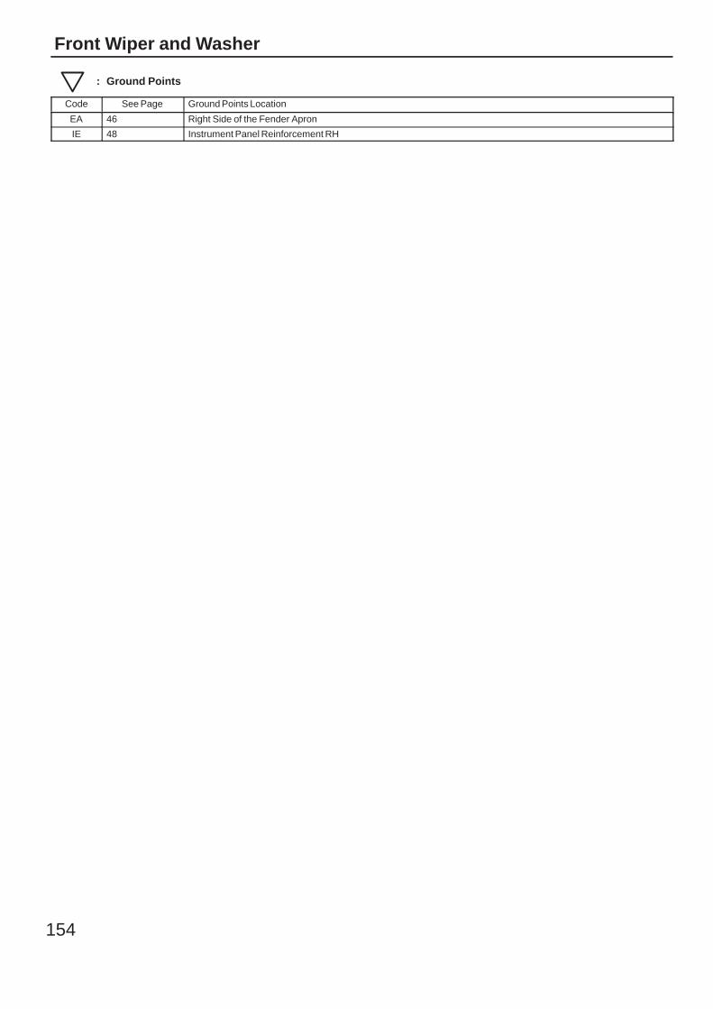
154
Front Wiper and Washer
: Ground Points
Code See Page Ground Points Location
EA 46 Right Side of the Fender Apron
IE 48 Instrument Panel Reinforcement RH

155
Memo
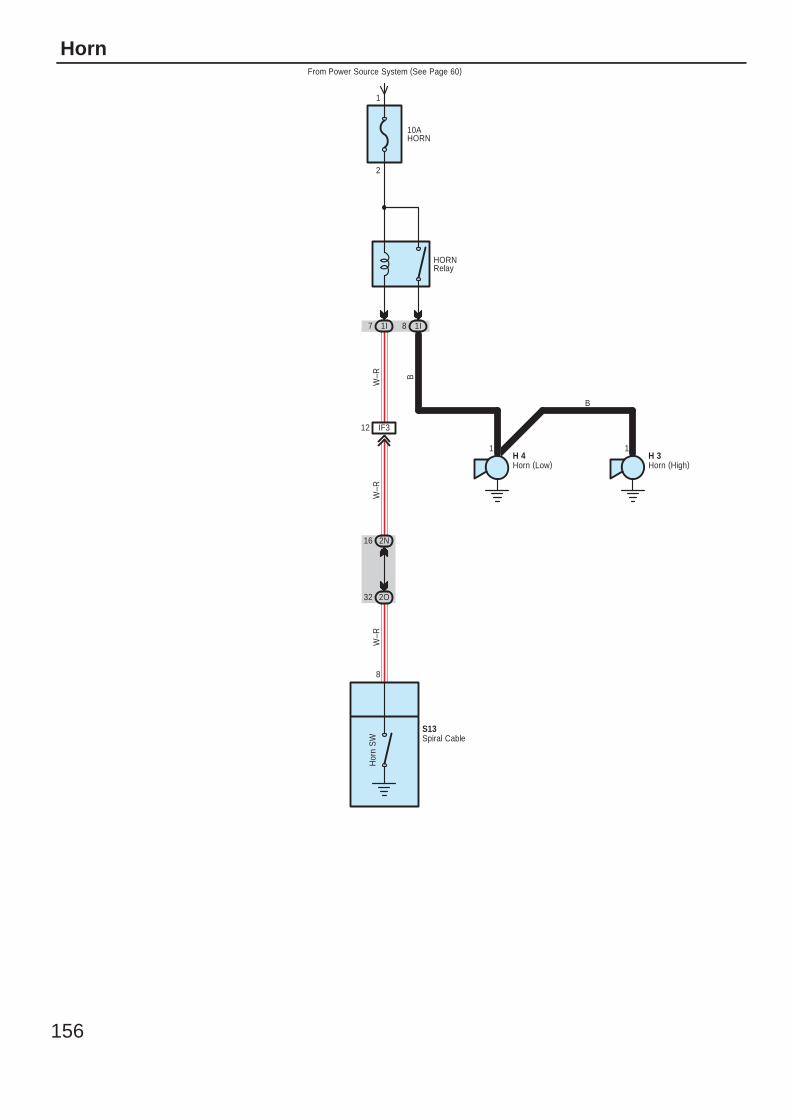
156
Horn
10AHORN
From Power Source System (See Page 60)
2
1
1I7 1I8
IF312
1 1
2O32
2N16
Hor
n S
WW
–R B
W–R
W–R
B
H 4 H 3
HORNRelay
8
Horn (High)Horn (Low)
Spiral CableS13
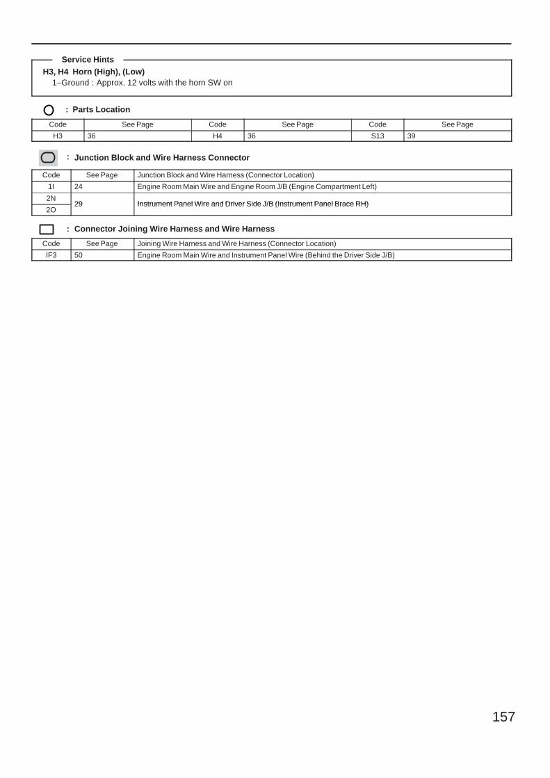
157
H3, H4 Horn (High), (Low)1–Ground : Approx. 12 volts with the horn SW on
: Parts Location
Code See Page Code See Page Code See Page
H3 36 H4 36 S13 39
: Junction Block and Wire Harness Connector
Code See Page Junction Block and Wire Harness (Connector Location)
1I 24 Engine Room Main Wire and Engine Room J/B (Engine Compartment Left)
2N29 Instrument Panel Wire and Driver Side J/B (Instrument Panel Brace RH)
2O29 Instrument Panel Wire and Driver Side J/B (Instrument Panel Brace RH)
: Connector Joining Wire Harness and Wire Harness
Code See Page Joining Wire Harness and Wire Harness (Connector Location)
IF3 50 Engine Room Main Wire and Instrument Panel Wire (Behind the Driver Side J/B)
Service Hints
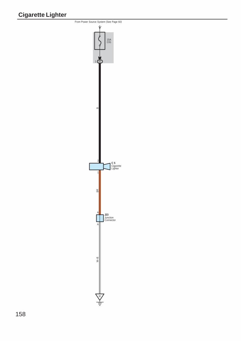
158
Cigarette Lighter
15ACIG
IE
BR
W–B
From Power Source System (See Page 60)
2C1
1
2
B
C 5
A
A
J23
CigaretteLighter
JunctionConnector
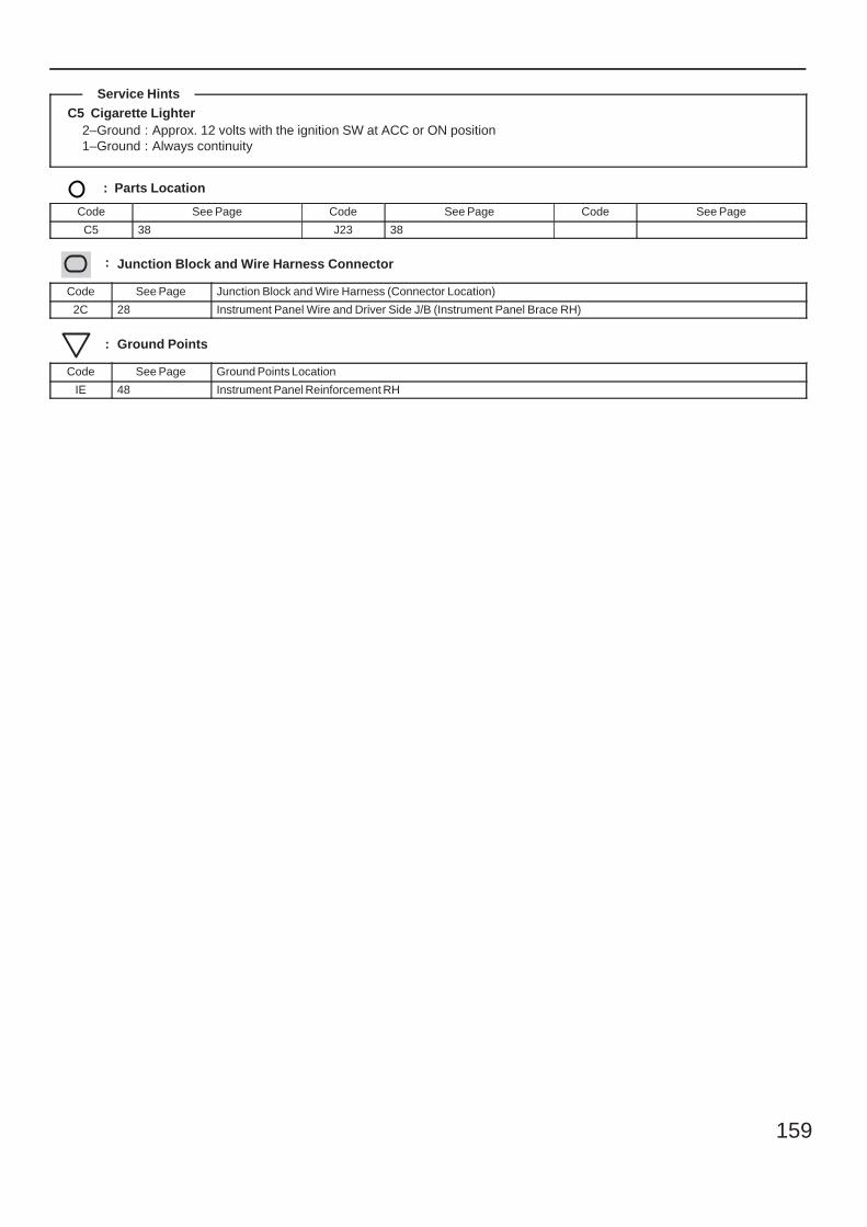
159
C5 Cigarette Lighter2–Ground : Approx. 12 volts with the ignition SW at ACC or ON position1–Ground : Always continuity
: Parts Location
Code See Page Code See Page Code See Page
C5 38 J23 38
: Junction Block and Wire Harness Connector
Code See Page Junction Block and Wire Harness (Connector Location)
2C 28 Instrument Panel Wire and Driver Side J/B (Instrument Panel Brace RH)
: Ground Points
Code See Page Ground Points Location
IE 48 Instrument Panel Reinforcement RH
Service Hints
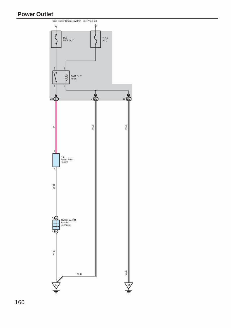
160
Power Outlet
15APWR OUT
7. 5AACC
3 1
5 2
2
1
2P23 2D9
IE
AA
BA
ID
2D18
PW
–BW
–B
W–B
W–B
W–B
W–B
P 3
J22(A), J23(B)
PWR OUTRelay
From Power Source System (See Page 60)
JunctionConnector
Power PointSocket
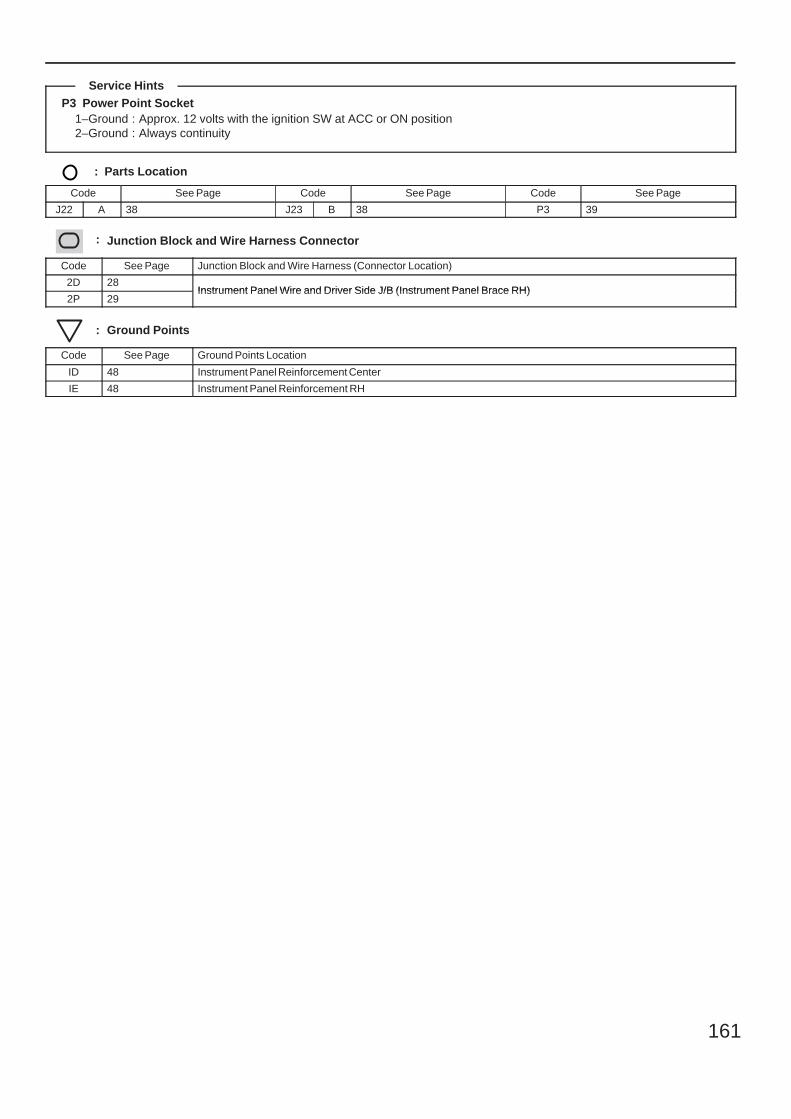
161
P3 Power Point Socket1–Ground : Approx. 12 volts with the ignition SW at ACC or ON position2–Ground : Always continuity
: Parts Location
Code See Page Code See Page Code See Page
J22 A 38 J23 B 38 P3 39
: Junction Block and Wire Harness Connector
Code See Page Junction Block and Wire Harness (Connector Location)
2D 28Instrument Panel Wire and Driver Side J/B (Instrument Panel Brace RH)
2P 29Instrument Panel Wire and Driver Side J/B (Instrument Panel Brace RH)
: Ground Points
Code See Page Ground Points Location
ID 48 Instrument Panel Reinforcement Center
IE 48 Instrument Panel Reinforcement RH
Service Hints
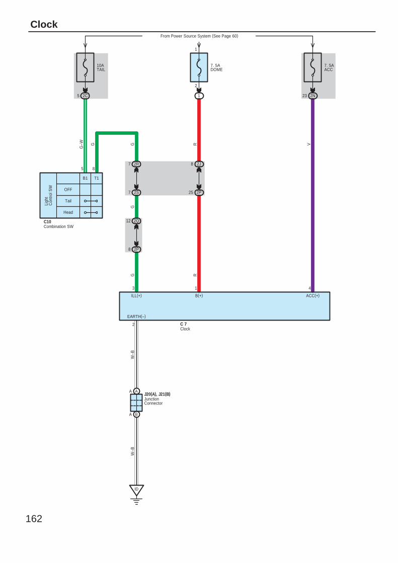
162
Clock
B(+)
1
25 2P
8 2J
R
7. 5ADOME
From Power Source System (See Page 60)
1
2
1
7. 5AACC
2N23
VR
ACC(+)
4
10ATAIL
2C5
OFF
Tail
Head
Ligh
tC
ontro
l SW
2S7
2R7
2Q12
2P8
ILL(+)
3
G–W G G
GG
5 8
C10
C 7
ID
AA
BA
J20(A), J21(B)
2
EARTH(–)
W–B
W–B
B1 T1
Clock
Combination SW
JunctionConnector
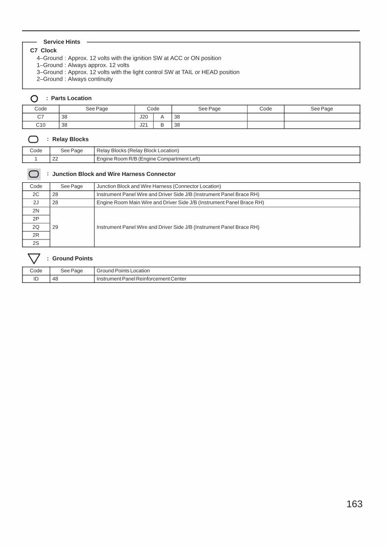
163
C7 Clock4–Ground : Approx. 12 volts with the ignition SW at ACC or ON position1–Ground : Always approx. 12 volts3–Ground : Approx. 12 volts with the light control SW at TAIL or HEAD position2–Ground : Always continuity
: Parts Location
Code See Page Code See Page Code See Page
C7 38 J20 A 38
C10 38 J21 B 38
: Relay Blocks
Code See Page Relay Blocks (Relay Block Location)
1 22 Engine Room R/B (Engine Compartment Left)
: Junction Block and Wire Harness Connector
Code See Page Junction Block and Wire Harness (Connector Location)
2C 28 Instrument Panel Wire and Driver Side J/B (Instrument Panel Brace RH)
2J 28 Engine Room Main Wire and Driver Side J/B (Instrument Panel Brace RH)
2N
29 Instrument Panel Wire and Driver Side J/B (Instrument Panel Brace RH)
2P
29 Instrument Panel Wire and Driver Side J/B (Instrument Panel Brace RH)2Q 29 Instrument Panel Wire and Driver Side J/B (Instrument Panel Brace RH)
2R
29 Instrument Panel Wire and Driver Side J/B (Instrument Panel Brace RH)
2S
: Ground Points
Code See Page Ground Points Location
ID 48 Instrument Panel Reinforcement Center
Service Hints
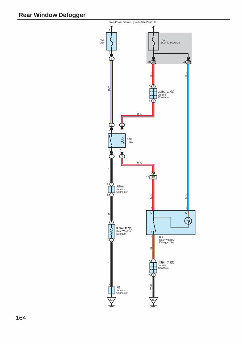
164
Rear Window Defogger
20ADEF
From Power Source System (See Page 60)
3
2
1
IE
BA
3 3
33
IH112
BE
AD
A1
B1
AA
10AECU–IG&GAUGE
2K8 2R4
4 5
5 1
3 2
3
J16(A), J17(B)
J22(A), J23(B)
R 3
BB
W–B
BR
R–L
BB
–Y
R–L
R–L
R–L
R–L
DEFRelay
D IG
E
JunctionConnector
JunctionConnector
Rear WindowDefogger SW
Rear WindowDefogger
R 6(A), R 7(B)
IG
JunctionConnector
J15A
J16(A)JunctionConnector
R–L
AE
AE
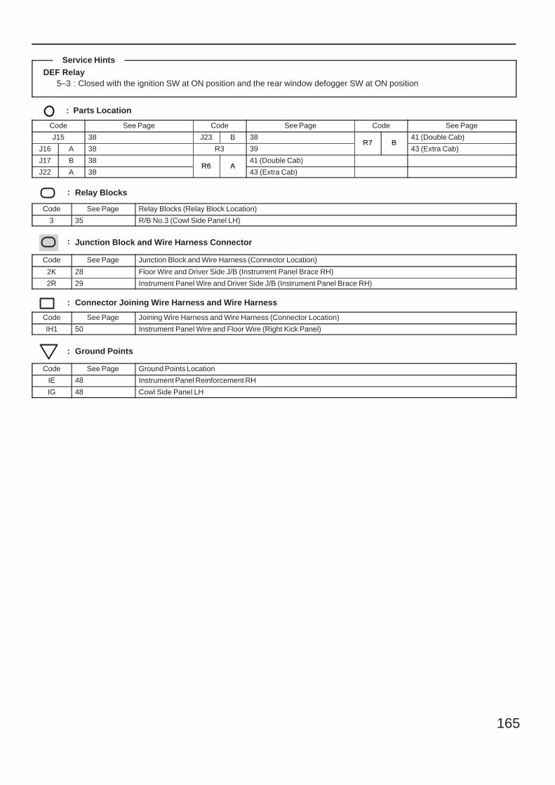
165
DEF Relay5–3 : Closed with the ignition SW at ON position and the rear window defogger SW at ON position
: Parts Location
Code See Page Code See Page Code See Page
J15 38 J23 B 38R7 B
41 (Double Cab)
J16 A 38 R3 39R7 B
43 (Extra Cab)
J17 B 38R6 A
41 (Double Cab)
J22 A 38R6 A
43 (Extra Cab)
: Relay Blocks
Code See Page Relay Blocks (Relay Block Location)
3 35 R/B No.3 (Cowl Side Panel LH)
: Junction Block and Wire Harness Connector
Code See Page Junction Block and Wire Harness (Connector Location)
2K 28 Floor Wire and Driver Side J/B (Instrument Panel Brace RH)
2R 29 Instrument Panel Wire and Driver Side J/B (Instrument Panel Brace RH)
: Connector Joining Wire Harness and Wire Harness
Code See Page Joining Wire Harness and Wire Harness (Connector Location)
IH1 50 Instrument Panel Wire and Floor Wire (Right Kick Panel)
: Ground Points
Code See Page Ground Points Location
IE 48 Instrument Panel Reinforcement RH
IG 48 Cowl Side Panel LH
Service Hints
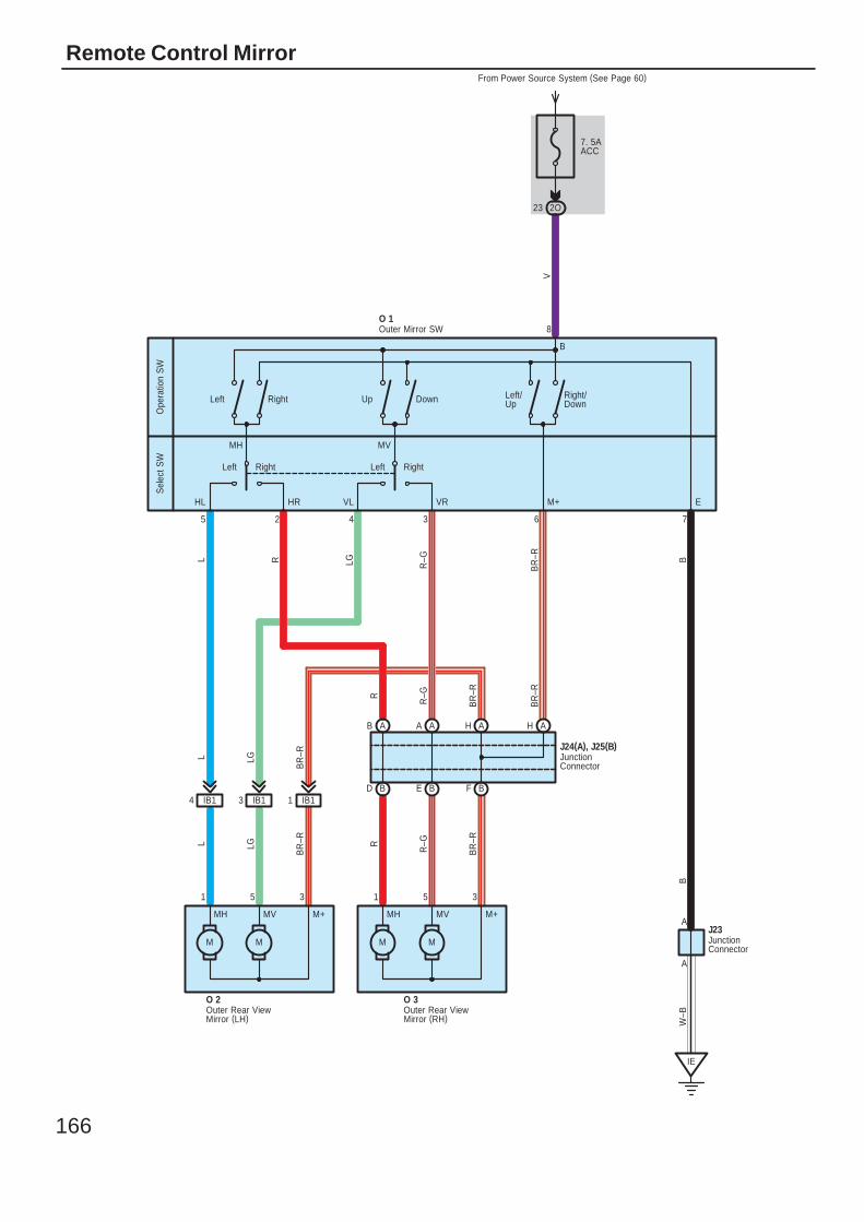
166
Remote Control Mirror
7. 5AACC
From Power Source System (See Page 60)
O 2 O 3
MMMM
351351
BFBEBDIB11IB13IB14
BR
–R
R–GR
BR
–R
LGL
MH MV M+ MH MV M+
AHAHAAAB
O 1
2O23
VB
R–R B
R–GLGRL
L LG
BR
–R
R–GR
BR
–R
BR
–R
IE
W–B
A
AJ23
B
5 2 4 3 6 7
8
VLHL HR VR M+ E
DownRight UpLeft
B
LeftLeft Right
Left/Up
Right/Down
Right
MH MV
Ope
ratio
n S
WS
elec
t SW
J24(A), J25(B)
JunctionConnector
JunctionConnector
Outer Mirror SW
Outer Rear ViewMirror (LH)
Outer Rear ViewMirror (RH)
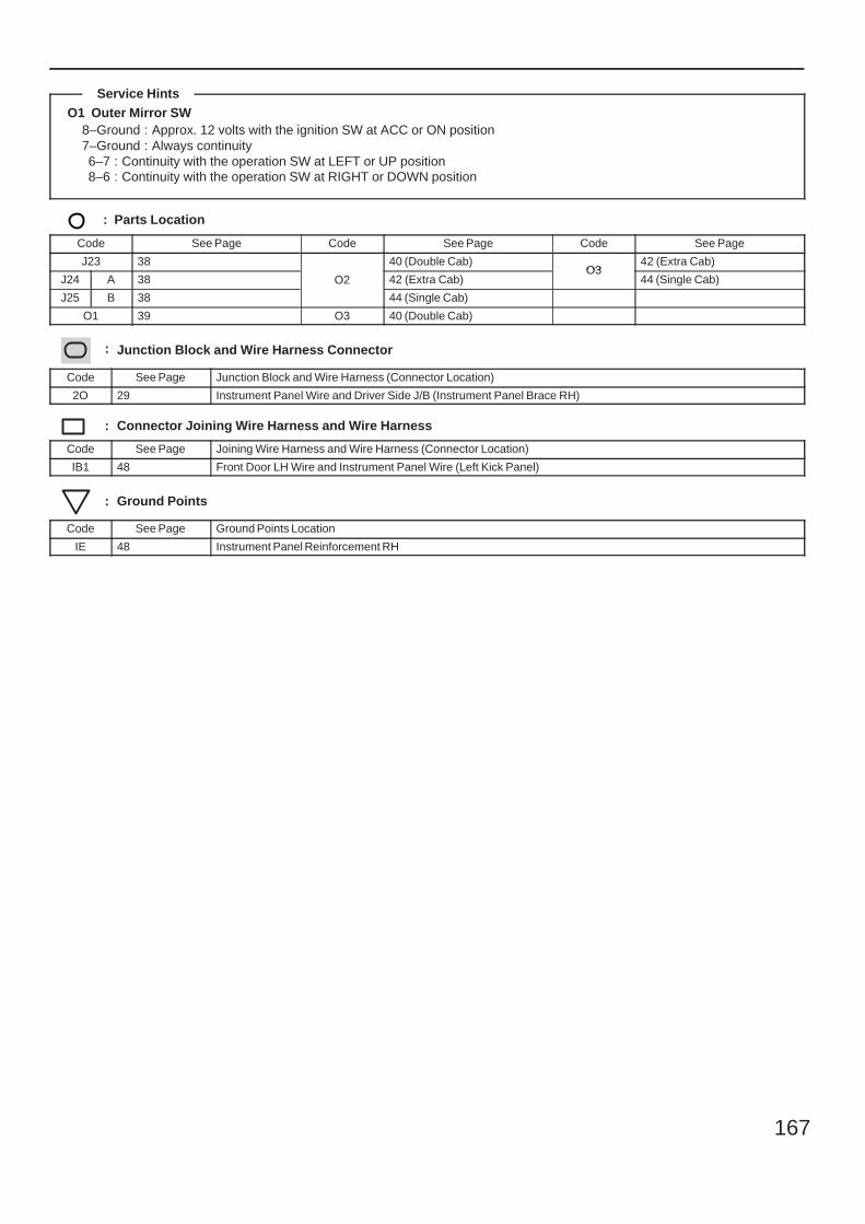
167
O1 Outer Mirror SW8–Ground : Approx. 12 volts with the ignition SW at ACC or ON position7–Ground : Always continuity6–7 : Continuity with the operation SW at LEFT or UP position8–6 : Continuity with the operation SW at RIGHT or DOWN position
: Parts Location
Code See Page Code See Page Code See Page
J23 38
O2
40 (Double Cab)O3
42 (Extra Cab)
J24 A 38 O2 42 (Extra Cab)O3
44 (Single Cab)
J25 B 38
O2
44 (Single Cab)
O1 39 O3 40 (Double Cab)
: Junction Block and Wire Harness Connector
Code See Page Junction Block and Wire Harness (Connector Location)
2O 29 Instrument Panel Wire and Driver Side J/B (Instrument Panel Brace RH)
: Connector Joining Wire Harness and Wire Harness
Code See Page Joining Wire Harness and Wire Harness (Connector Location)
IB1 48 Front Door LH Wire and Instrument Panel Wire (Left Kick Panel)
: Ground Points
Code See Page Ground Points Location
IE 48 Instrument Panel Reinforcement RH
Service Hints
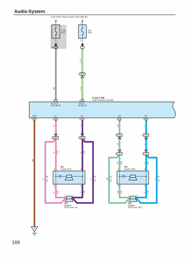
168
Audio System
3
GR
BR
P V LG L
LG L
1
FR+
+B(∗7)BU+B(∗8)
GND FL+ FL– FR–
LLG
1 2
L–Y
( ∗1)
( ∗1)
( ∗1)
( ∗1)
4 2
S16
T24
L
( ∗2,
∗3)
LG
( ∗2,
∗3)
LLG
3
P V
1
VP
1 2
( ∗1)
( ∗1)
( ∗1)
( ∗1)
4 2
S15
T23
V
( ∗2,
∗3)
P
( ∗2,
∗3)
R 1(A), R 2(B)A3
ACC(∗7)ACC+B(∗8)
7. 5AACC
From Power Source System (See Page 60)
2N24
A4
IF22
15ARAD
1
2
A7 A2 A6 A1 A5
ID
1
IH14IH19IB16 IB15
II17II18
L–Y
Radio Receiver Assembly
Speaker(Front Door LH)
Speaker(Front Door RH)
Tweeter (LH) Tweeter (RH)
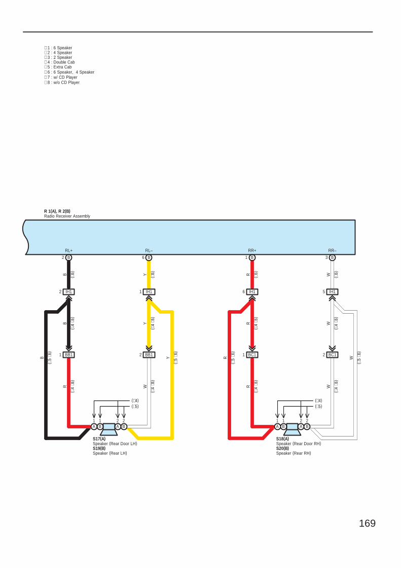
169
∗ 4 : Double CabB Y
R W
R WR W
∗ 3 : 2 Speaker
RL+ RL– RR+ RR–
YB
∗ 1 : 6 Speaker∗ 2 : 4 Speaker
W
R
S18(A)
B2 B6 B1 B3
IH15IH16IH11IH12
BB11 BB12 BC11 BC12
R 1(A), R 2(B)Radio Receiver Assembly
∗ 5 : Extra Cab
W
RYB
( ∗5
∗6)
( ∗4
∗6)
( ∗4
∗6)
( ∗4
∗6)
( ∗4
∗6)
( ∗5
∗6)
( ∗5
∗6)
( ∗4
∗6)
( ∗4
∗6)
( ∗5
∗6)
( ∗4
∗6)
( ∗4
∗6)
∗ 6 : 6 Speaker, 4 Speaker
( ∗6)
( ∗6)
( ∗6)
( ∗6)
Speaker (Rear Door RH)
A2
B2
B1
A1
(∗4)(∗5)
S20(B)Speaker (Rear RH)
1
S17(A)Speaker (Rear Door LH)
Speaker (Rear LH)S19(B)
(∗5)(∗4)
BA1
A B2 2
∗ 7 : w/ CD Player∗ 8 : w/o CD Player
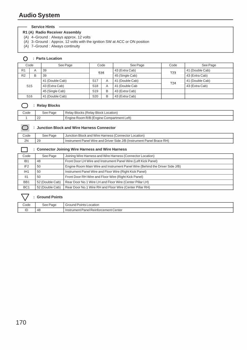
170
Audio System
R1 (A) Radio Receiver Assembly(A) 4–Ground : Always approx. 12 volts(A) 3–Ground : Approx. 12 volts with the ignition SW at ACC or ON position(A) 7–Ground : Always continuity
: Parts Location
Code See Page Code See Page Code See Page
R1 A 39S16
43 (Extra Cab)T23
41 (Double Cab)
R2 B 39S16
45 (Single Cab)T23
43 (Extra Cab)
S15
41 (Double Cab) S17 A 41 (Double Cab)T24
41 (Double Cab)
S15 43 (Extra Cab) S18 A 41 (Double CabT24
43 (Extra Cab)S15
45 (Single Cab) S19 B 43 (Extra Cab)
S16 41 (Double Cab) S20 B 43 (Extra Cab)
: Relay Blocks
Code See Page Relay Blocks (Relay Block Location)
1 22 Engine Room R/B (Engine Compartment Left)
: Junction Block and Wire Harness Connector
Code See Page Junction Block and Wire Harness (Connector Location)
2N 29 Instrument Panel Wire and Driver Side J/B (Instrument Panel Brace RH)
: Connector Joining Wire Harness and Wire Harness
Code See Page Joining Wire Harness and Wire Harness (Connector Location)
IB1 48 Front Door LH Wire and Instrument Panel Wire (Left Kick Panel)
IF2 50 Engine Room Main Wire and Instrument Panel Wire (Behind the Driver Side J/B)
IH1 50 Instrument Panel Wire and Floor Wire (Right Kick Panel)
II1 50 Front Door RH Wire and Floor Wire (Right Kick Panel)
BB1 52 (Double Cab) Rear Door No.1 Wire LH and Floor Wire (Center Pillar LH)
BC1 52 (Double Cab) Rear Door No.1 Wire RH and Floor Wire (Center Pillar RH)
: Ground Points
Code See Page Ground Points Location
ID 48 Instrument Panel Reinforcement Center
Service Hints

171
Memo
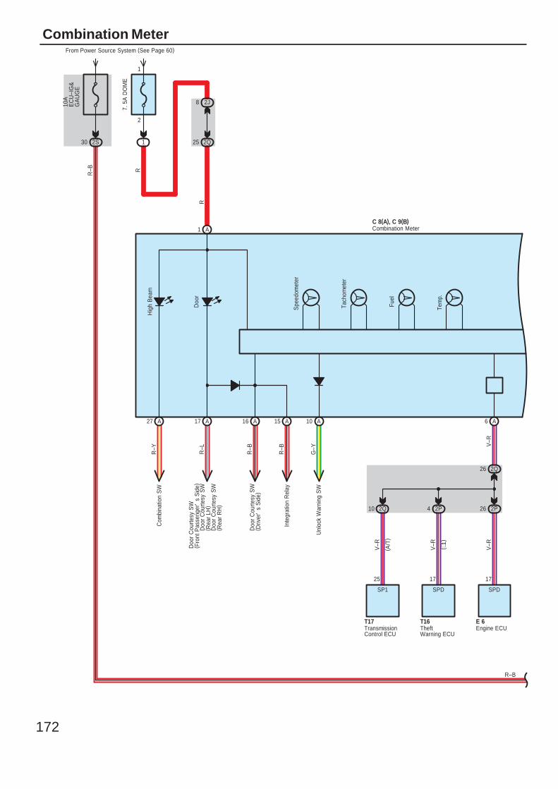
172
Combination Meter
Com
bina
tion
SW
R
Spe
edom
eter
Tach
omet
er
Fuel
Tem
p.
Doo
r
Hig
h B
eam
V–R
V–R
V–R
( A/T
)
( ∗1)
V–R
R–B
7. 5
A D
OM
E
From Power Source System (See Page 60)
1
2
1
2J8
2Q25R
10A
EC
U–I
G&
GA
UG
E
2S30
A1
2Q26
2P262P42Q10
A6
Doo
r C
ourte
sy S
W( R
ear
RH
)
Doo
r C
ourte
sy S
W( D
river
's
Sid
e)
Inte
grat
ion
Rel
ay
Unl
ock
War
ning
SW
R–Y
R–L
R–B
R–B
G–Y
Doo
r C
ourte
sy S
W( R
ear
LH)
Doo
r C
ourte
sy S
W( F
ront
Pas
seng
er'
s S
ide)
17
SPD
E 6
SPD
17
T16
SP1
25
T17
C 8(A), C 9(B)
R–B
A27 A17 A16 A15 A10
Engine ECU
Combination Meter
TransmissionControl ECU
TheftWarning ECU
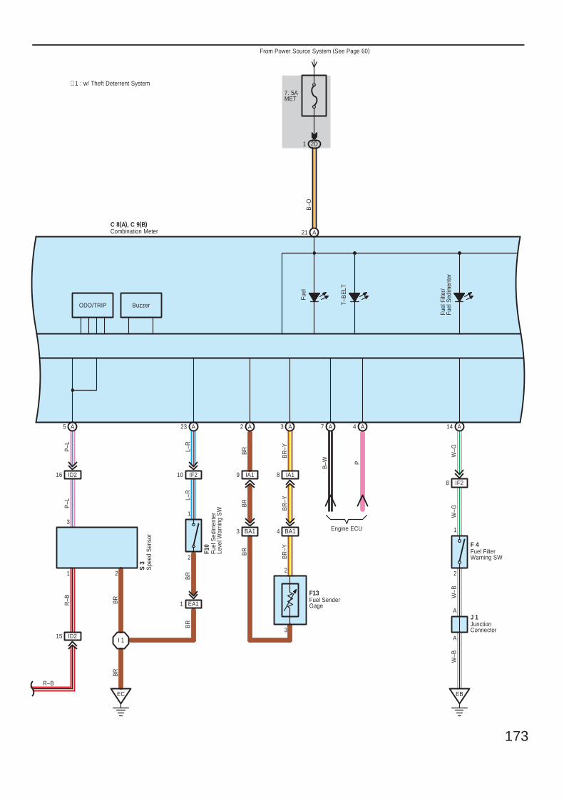
173
T–B
ELT
Fuel
B–O
B–W P
P–L
ODO/TRIP
3
2
BR
–Y
BR
BR
BR
–Y
Buzzer
BR
BR
R–B
P–L
1 2
3
L–R
2
1
L–R
BR
BR
–Y
Fuel
Filt
er/
Fuel
Sed
imen
ter
2
1
W–G
W–G
A
A
W–B
W–B
7. 5AMET
From Power Source System (See Page 60)
2D1
A21C 8(A), C 9(B)
I 1
EC
S 3
F10
IA19 IA18
BA13 BA14
BR
Engine ECU
ID215
ID216 IF210
EA11
A4A7A3A2A23A5
EB
IF28
F13
F 4
J 1
A14
∗ 1 : w/ Theft Deterrent System
R–B
Combination Meter
Fuel FilterWarning SW
Fuel
Sed
imen
ter
Leve
l War
ning
SW
Fuel SenderGage
JunctionConnector
Spe
ed S
enso
r
BR
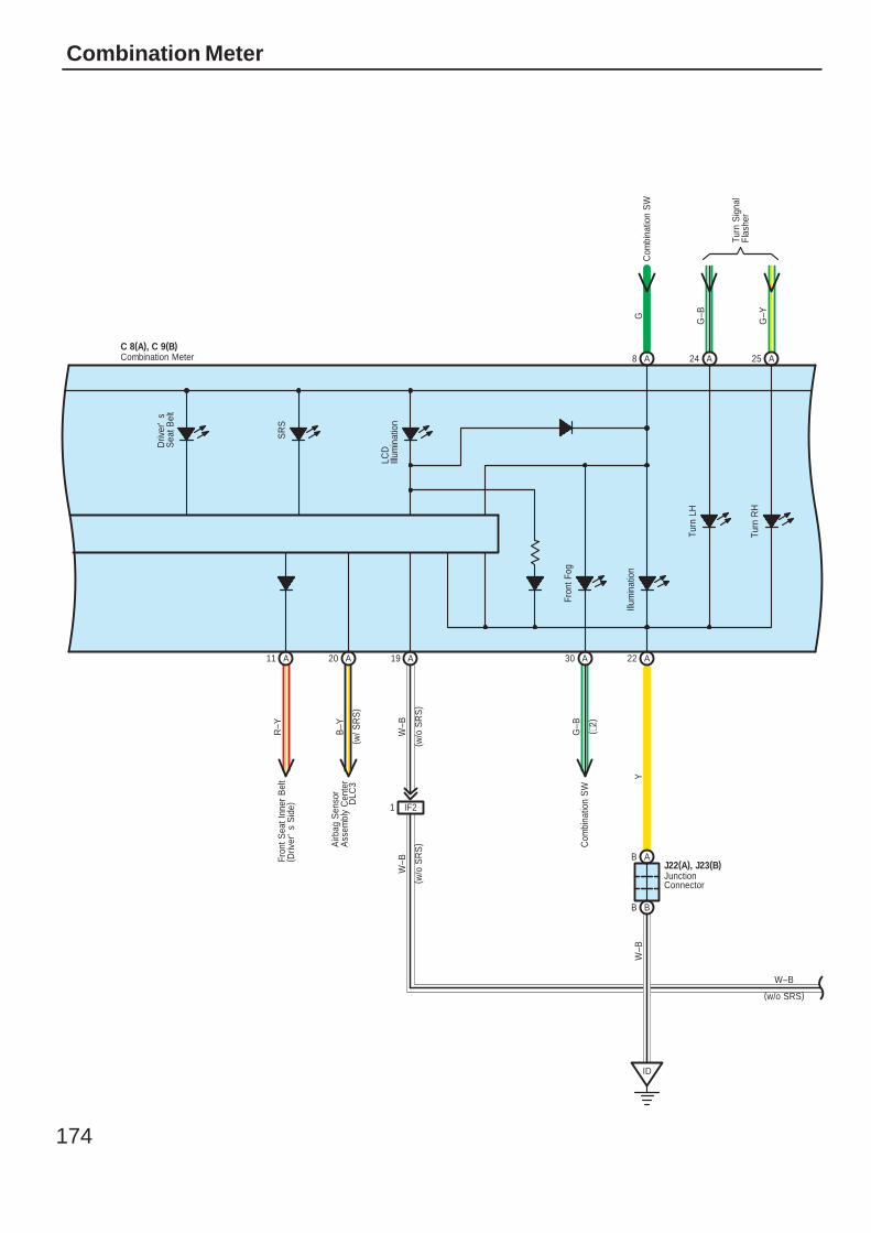
174
Combination Meter
Driv
er'
sS
eat B
elt
SR
SFr
ont S
eat I
nner
Bel
t( D
river
's
Sid
e)
Com
bina
tion
SW
Illum
inat
ion
Fron
t Fog
YW
–B
( w/o
SR
S)
W–B
( w/o
SR
S)
W–B
( w/ S
RS
)C 8(A), C 9(B)
GC
ombi
natio
n S
W
A8
ID
R–Y
B–Y
A22A30A19A20A11
IF21
DLC
3
Airb
ag S
enso
rA
ssem
bly
Cen
ter
G–B
( ∗2)
J22(A), J23(B)AB
BB
Turn
LH
Turn
RH
G–B
G–Y
Turn
Sig
nal
Flas
her
A24 A25
W–B
(w/o SRS)
Combination Meter
JunctionConnector
LCD
Illum
inat
ion
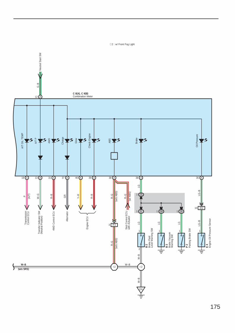
175
4WD
A/T
OIL
TE
MP
( A/T
)
P
A18
Tran
smis
sion
Con
trol E
CU
∗ 2 : w/ Front Fog Light
W–B
(w/o SRS)
A
1
2L
2S
1 2K
Glo
w
Alte
rnat
or
Che
ck E
ngin
e
Cha
rge
Bra
ke
W–B
(w/o SRS)
( w/o
AB
S)
W–B
R–G
R–G
( w/o
AB
S)
1
( w/ A
BS
)
LG
1
35
AB
S
Ski
d C
ontro
l EC
Uw
ith A
ctua
tor
W–B
2
A36
LGW
–B
LG–B
LG
LG–B
LG
1 1
Oil
Pre
ssur
e
1
Eng
ine
EC
U
A37 A40 A39
R–B
Y–RGR
1 2MID210
IF23
A38
EA
I 2I 2
R–G
C 8(A), C 9(B)Combination Meter
W–G
A13
Tran
sfer
Indi
cato
r S
W( N
eutra
l Pos
ition
)
4WD
Con
trol E
CU
31 A
R–B
E 4
Par
king
Bra
ke S
WP
2
B 3
Bra
ke F
luid
Leve
l War
ning
SW
B 2
Bra
ke V
acuu
mW
arni
ng S
W
Eng
ine
Oil
Pre
ssur
e S
enso
r
G–B
Neu
tral S
tart
SW
A12
A/T
P
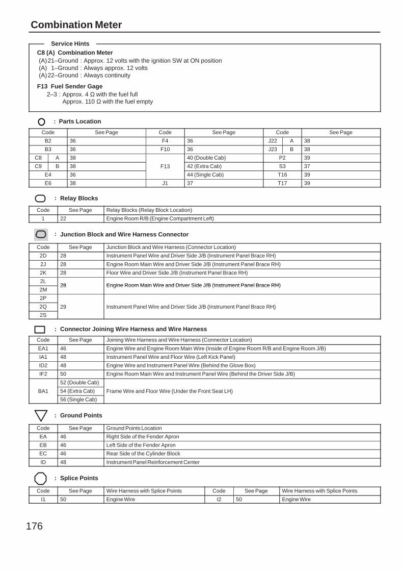
176
Combination Meter
C8 (A) Combination Meter(A)21–Ground : Approx. 12 volts with the ignition SW at ON position(A) 1–Ground : Always approx. 12 volts(A)22–Ground : Always continuity
F13 Fuel Sender Gage2–3 : Approx. 4 Ω with the fuel full
Approx. 110 Ω with the fuel empty
: Parts Location
Code See Page Code See Page Code See Page
B2 36 F4 36 J22 A 38
B3 36 F10 36 J23 B 38
C8 A 38
F13
40 (Double Cab) P2 39
C9 B 38 F13 42 (Extra Cab) S3 37
E4 36
F13
44 (Single Cab) T16 39
E6 38 J1 37 T17 39
: Relay Blocks
Code See Page Relay Blocks (Relay Block Location)
1 22 Engine Room R/B (Engine Compartment Left)
: Junction Block and Wire Harness Connector
Code See Page Junction Block and Wire Harness (Connector Location)
2D 28 Instrument Panel Wire and Driver Side J/B (Instrument Panel Brace RH)
2J 28 Engine Room Main Wire and Driver Side J/B (Instrument Panel Brace RH)
2K 28 Floor Wire and Driver Side J/B (Instrument Panel Brace RH)
2L28 Engine Room Main Wire and Driver Side J/B (Instrument Panel Brace RH)
2M28 Engine Room Main Wire and Driver Side J/B (Instrument Panel Brace RH)
2P
29 Instrument Panel Wire and Driver Side J/B (Instrument Panel Brace RH)2Q 29 Instrument Panel Wire and Driver Side J/B (Instrument Panel Brace RH)
2S
29 Instrument Panel Wire and Driver Side J/B (Instrument Panel Brace RH)
: Connector Joining Wire Harness and Wire Harness
Code See Page Joining Wire Harness and Wire Harness (Connector Location)
EA1 46 Engine Wire and Engine Room Main Wire (Inside of Engine Room R/B and Engine Room J/B)
IA1 48 Instrument Panel Wire and Floor Wire (Left Kick Panel)
ID2 48 Engine Wire and Instrument Panel Wire (Behind the Glove Box)
IF2 50 Engine Room Main Wire and Instrument Panel Wire (Behind the Driver Side J/B)
BA1
52 (Double Cab)
Frame Wire and Floor Wire (Under the Front Seat LH)BA1 54 (Extra Cab) Frame Wire and Floor Wire (Under the Front Seat LH)BA1
56 (Single Cab)
Frame Wire and Floor Wire (Under the Front Seat LH)
: Ground Points
Code See Page Ground Points Location
EA 46 Right Side of the Fender Apron
EB 46 Left Side of the Fender Apron
EC 46 Rear Side of the Cylinder Block
ID 48 Instrument Panel Reinforcement Center
: Splice Points
Code See Page Wire Harness with Splice Points Code See Page Wire Harness with Splice Points
I1 50 Engine Wire I2 50 Engine Wire
Service Hints

177
Memo
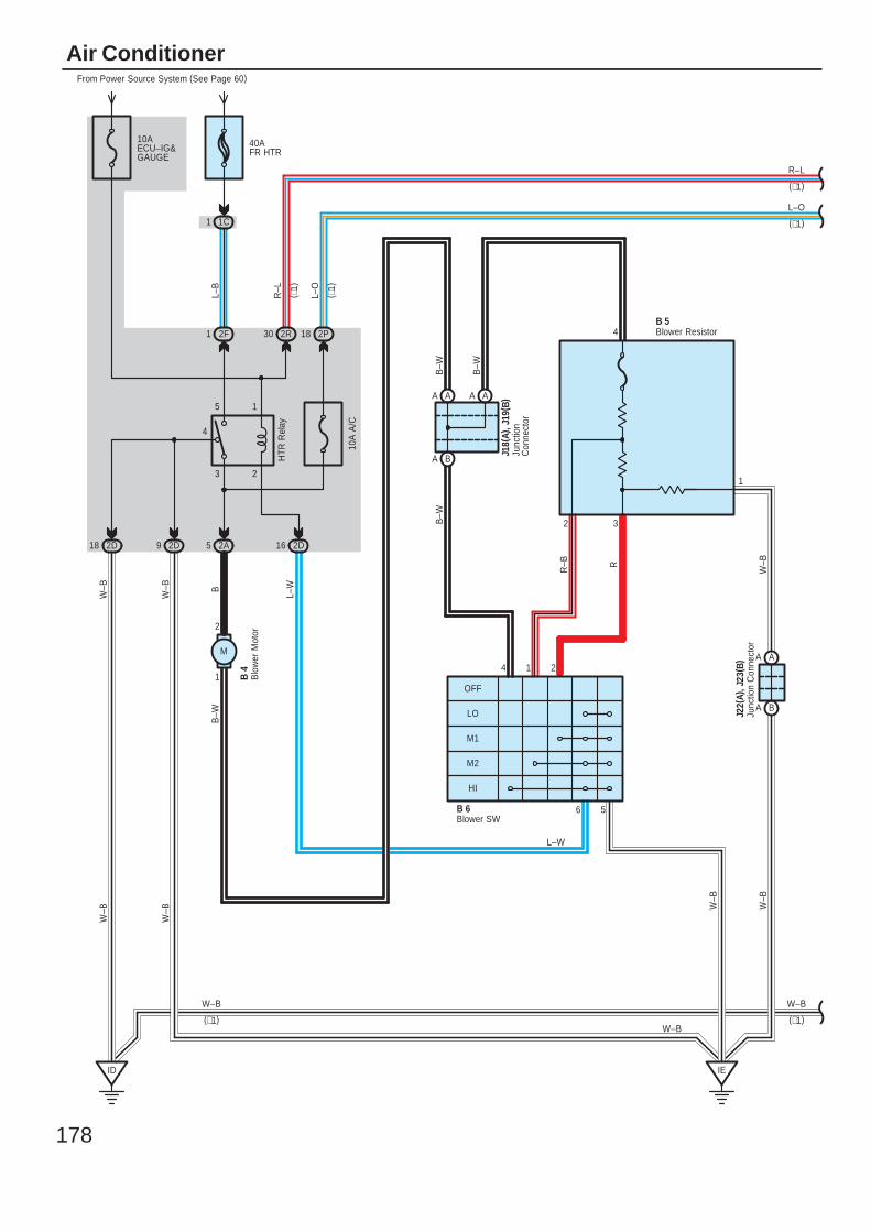
178
Air Conditioner
OFF
LO
1
W–B
B–W
W–B
B–W
L–W
B–W
W–B
W–B
(∗1)
4
M1
M2
HI
6 5
2
18 2P30 2R
5
ID
9 2D
1 1C
From Power Source System (See Page 60)
40AFR HTR
R–L
1 2F
B 4
W–B
W–B
W–B
W–B B
1
2
M
L–W
L–B
HTR
Rel
ay
4
1
2
5
3
10AECU–IG&GAUGE
18 2D
L–O
16 2D2A
( ∗1)
B–W
10A
A/C
( ∗1)
B 6
J22(
A), J
23( B
) AA
BA
BA
AA AA
IE
R–L
(∗1)
L–O
(∗1)
W–B
(∗1)
Junc
tion
Con
nect
or
Blo
wer
Mot
or
Blower SW
32
4 Blower Resistor
Junc
tion
Con
nect
or
J18(
A), J
19( B
)
B 5
1
W–B
R–B R
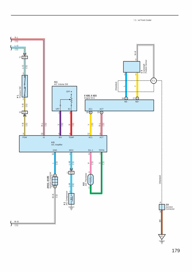
179
V
B/V TEMP
5
18
2
1
( ∗1)
10 14
1
2
78
Y–B
Y–B
L–O
R–L
6
R
2
SG–1 TEFIN
IG AC1 ACT
PY R–L
∗ 1 : w/ Front Cooler
MGC
L–WL ( ∗1)
GND
1
3
( ∗1)
L–W
1
( ∗1)
( ∗1)
( ∗1)
PSW
W–B
2
(∗1)
L–O( ∗
1)
( ∗1)
( ∗1)
( ∗1)
( ∗1)
( ∗1)
( ∗1)
( ∗1)
1
VRT E2
A10
A 1
J20(
A), J
21( B
)
P 1
A11
A 9
AA
BA
IF316
IF317
ID11
AC1
19 B
ACT
18 B
A
A
EC
( Shi
elde
d)B
R
27 DD34
NE+NE–
2 1
L Y
E 1
W–B
3
C 4
( Shi
elde
d)
E 6(B), E 8(D)
J10
R–L
(∗1)
W–B
(∗1)
A/C
Com
pres
sor
Pre
ssur
e S
W
A/C Amplifier
A/C
The
rmis
tor
Cra
nksh
aft
Pos
ition
Sen
sor
Engine ECU
JunctionConnector
Junc
tion
Con
nect
or
A/C Volume SW
OFF
G
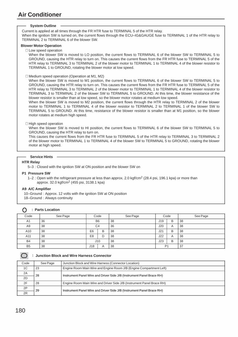
180
Air Conditioner
Current is applied at all times through the FR HTR fuse to TERMINAL 5 of the HTR relay.When the ignition SW is turned on, the current flows through the ECU–IG&GAUGE fuse to TERMINAL 1 of the HTR relay toTERMINAL 2 to TERMINAL 6 of the blower SW.
Blower Motor Operation∗ Low speed operation
When the blower SW is moved to LO position, the current flows to TERMINAL 6 of the blower SW to TERMINAL 5 toGROUND, causing the HTR relay to turn on. This causes the current flows from the FR HTR fuse to TERMINAL 5 of theHTR relay to TERMINAL 3 to TERMINAL 2 of the blower motor to TERMINAL 1 to TERMINAL 4 of the blower resistor toTERMINAL 1 to GROUND, rotating the blower motor at low speed.
∗ Medium speed operation (Operation at M1, M2)When the blower SW is moved to M1 position, the current flows to TERMINAL 6 of the blower SW to TERMINAL 5 toGROUND, causing the HTR relay to turn on. This causes the current flows from the FR HTR fuse to TERMINAL 5 of theHTR relay to TERMINAL 3 to TERMINAL 2 of the blower motor to TERMINAL 1 to TERMINAL 4 of the blower resistor toTERMINAL 3 to TERMINAL 2 of the blower SW to TERMINAL 5 to GROUND. At this time, the blower resistance of theblower resistor is smaller than at low speed, so the blower motor rotates at medium low speed.When the blower SW is moved to M2 position, the current flows through the HTR relay to TERMINAL 2 of the blowermotor to TERMINAL 1 to TERMINAL 4 of the blower resistor to TERMINAL 2 to TERMINAL 1 of the blower SW toTERMINAL 5 to GROUND. At this time, resistance of the blower resistor is smaller than at M1 position, so the blowermotor rotates at medium high speed.
∗ High speed operationWhen the blower SW is moved to HI position, the current flows to TERMINAL 6 of the blower SW to TERMINAL 5 toGROUND, causing the HTR relay to turn on.This causes the current flows from the FR HTR fuse to TERMINAL 5 of the HTR relay to TERMINAL 3 to TERMINAL 2of the blower motor to TERMINAL 1 to TERMINAL 4 of the blower SW to TERMINAL 5 to GROUND, rotating the blowermotor at high speed.
HTR Relay5–3 : Closed with the ignition SW at ON position and the blower SW on
P1 Pressure SW1–2 : Open with the refrigerant pressure at less than approx. 2.0 kgf/cm2 (28.4 psi, 196.1 kpa) or more than
approx. 32.0 kgf/cm2 (455 psi, 3138.1 kpa)
A9 A/C Amplifier10–Ground : Approx. 12 volts with the ignition SW at ON position18–Ground : Always continuity
: Parts Location
Code See Page Code See Page Code See Page
A1 36 B6 38 J19 B 38
A9 38 C4 36 J20 A 38
A10 38 E6 B 38 J21 B 38
A11 38 E8 D 38 J22 A 38
B4 38 J10 38 J23 B 38
B5 38 J18 A 38 P1 37
: Junction Block and Wire Harness Connector
Code See Page Junction Block and Wire Harness (Connector Location)
1C 23 Engine Room Main Wire and Engine Room J/B (Engine Compartment Left)
2A28 Instrument Panel Wire and Driver Side J/B (Instrument Panel Brace RH)
2D28 Instrument Panel Wire and Driver Side J/B (Instrument Panel Brace RH)
2F 28 Engine Room Main Wire and Driver Side J/B (Instrument Panel Brace RH)
2P29 Instrument Panel Wire and Driver Side J/B (Instrument Panel Brace RH)
2R29 Instrument Panel Wire and Driver Side J/B (Instrument Panel Brace RH)
System Outline
Service Hints
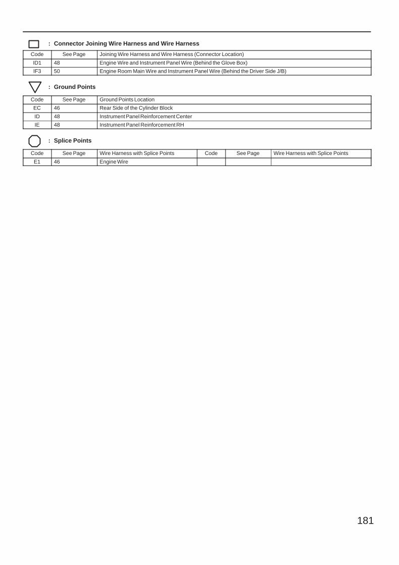
181
: Connector Joining Wire Harness and Wire Harness
Code See Page Joining Wire Harness and Wire Harness (Connector Location)
ID1 48 Engine Wire and Instrument Panel Wire (Behind the Glove Box)
IF3 50 Engine Room Main Wire and Instrument Panel Wire (Behind the Driver Side J/B)
: Ground Points
Code See Page Ground Points Location
EC 46 Rear Side of the Cylinder Block
ID 48 Instrument Panel Reinforcement Center
IE 48 Instrument Panel Reinforcement RH
: Splice Points
Code See Page Wire Harness with Splice Points Code See Page Wire Harness with Splice Points
E1 46 Engine Wire
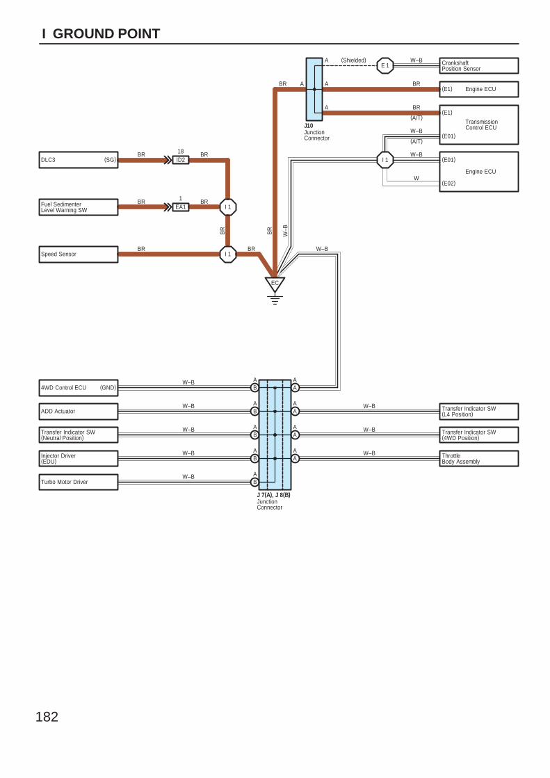
182
I GROUND POINT
CrankshaftPosition Sensor
(E1)
(E01)
(E01)
(E02)
DLC3
Fuel SedimenterLevel Warning SW
Speed Sensor
EC
I 1
E 1
I 1
I 1
ID218
EA11
BR
BR
W–B
BR
BR
BR W–B
W
W–B
W–B
BR
BR
W–B(Shielded)
BR
J10
BR
(A/T)
(A/T)
A
A
A
A
TransmissionControl ECU
(E1) Engine ECU
Engine ECU
(SG)
BR
BR
BA
BA
BA
BA
BA
AA
AA
AA
AA
Transfer Indicator SW(L4 Position)
Transfer Indicator SW(4WD Position)
ThrottleBody Assembly
ADD Actuator
Transfer Indicator SW(Neutral Position)
4WD Control ECU
Injector Driver(EDU)
Turbo Motor Driver
W–B
W–B
W–B
W–B
W–B
W–B
W–B
W–B
J 7(A), J 8(B)
(GND)
JunctionConnector
JunctionConnector
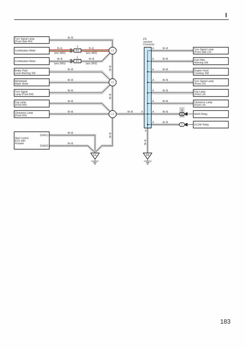
183
I
Combination Meter
Combination Meter
Brake FluidLevel Warning SW
WindshieldWiper Motor
Turn SignalLamp (Front RH)
Fog Lamp(Front RH)
Clearance Lamp(Front RH)
Fuel FilterWarning SW
Engine HoodCourtesy SW
Turn Signal Lamp(Front LH)
Fog Lamp(Front LH)
Clearance Lamp(Front LH)
MAIN Relay
GLOW Relay
Skid ControlECU withActuator
IF23
IF21
I 2
I 2
I 2
EA
(GND1)
(GND2)
EB
1J3
1
A W–B
A W–B
A W–B
A W–B
A W–B
A W–B
A W–B
A
A
W–B
R–G
W–B
W–B
W–B
W–B
W–B
W–B
W–B
W–BW
–BW
–BW
–B
W–B
J 1
R–G
W–B
(w/o ABS)(w/o ABS)
(w/o SRS) (w/o SRS)
Turn Signal Lamp(Front Side RH)
Turn Signal Lamp(Front Side LH)
W–BA
W–B
JunctionConnector
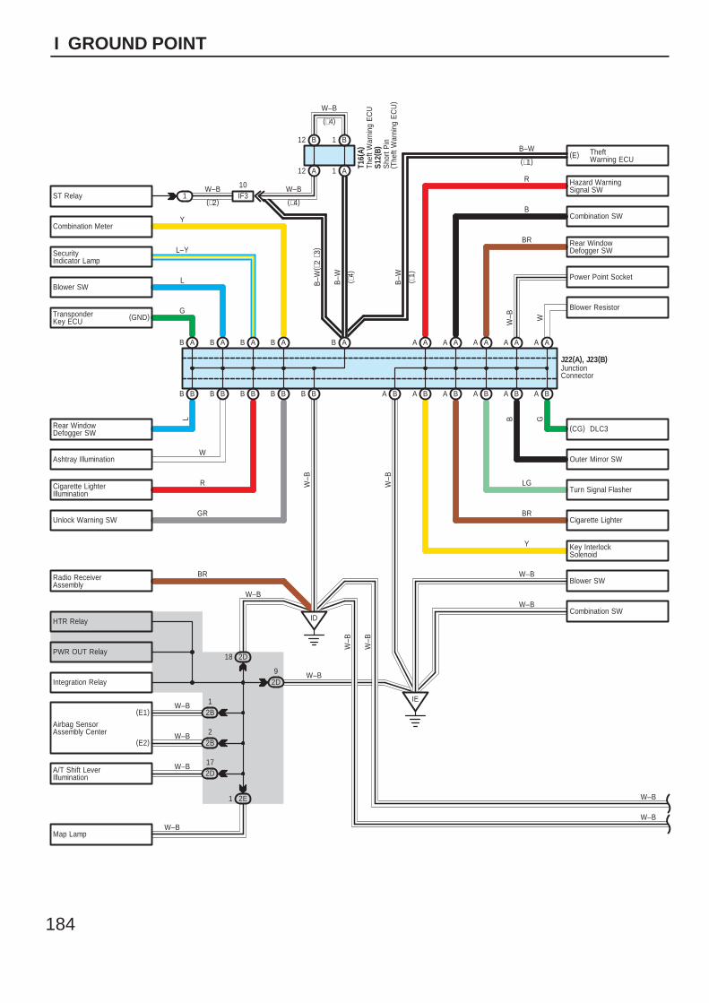
184
I GROUND POINT
ST Relay
Combination Meter
SecurityIndicator Lamp
Blower SW
Hazard WarningSignal SW
Combination SW
Rear WindowDefogger SW
Power Point Socket
Blower Resistor
(CG)
Outer Mirror SW
Turn Signal Flasher
Cigarette Lighter
Key InterlockSolenoid
Blower SW
Combination SW
Rear WindowDefogger SW
Ashtray Illumination
Cigarette LighterIllumination
Unlock Warning SW
Radio ReceiverAssembly
Integration Relay
Airbag SensorAssembly Center
A/T Shift LeverIllumination
Map Lamp
1
B–W
W–B
BB
AB
BB BB
AB
BB BB
AB AB
IF310 W–B
B12 B1
A12 A1
ID
A AA A
A BA B
A AA A
A BA B
A A
A BBA
IE
S12(
B)
T16(
A)
Y
L–Y
W
R
GR
BR
R
B
BR
LG
BR
Y
W–B
W–B
J22(A), J23(B)
GL
W–B
(∗4)
W
DLC3
W–B
W–B
W–B
B
2D9
2D18
2B1
2E1
W–B
W–B
W–B
2B2W–B
2D17W–B
W–B
(E1)
(E2)
W–B
W–B
W–B
W–B
B–W
(∗1)
( ∗4)
B–W ( ∗1)
(∗4)(∗2)
B A
L
TransponderKey ECU
(GND)G
PWR OUT Relay
HTR Relay
B–W
( ∗2
∗3)
JunctionConnector
Sho
rt P
in( T
heft
War
ning
EC
U)
(E) TheftWarning ECU
Thef
t War
ning
EC
U
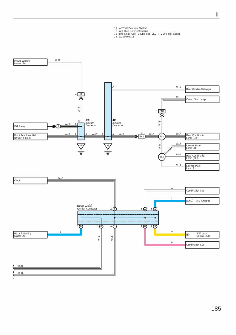
185
I
Combination SW
(GND)
Combination SW
Hazard WarningSignal SW
∗ 1 : w/ Theft Deterrent System∗ 2 : w/o Theft Deterrent System
BA
AA
B B B B B A BA
J20(A), J21(B)
L
W
L
Y
P
W–B
W–B
W–B
W–B
Rear CombinationLamp (LH)
Power WindowMaster SW
IG1 Relay
Front Seat Inner Belt(Driver' s Side)
IF
3A
AW–B
W–B
J28
IG
AA A
J15
W–BW–B
ClockW–B
AA
BA18W–B
B 3
License PlateLamp LH
Rear CombinationLamp (RH)
License PlateLamp RH
B 3
A
II14
W–B
W–B
Center Stop Lamp
Rear Window Defogger
BD11
A
W–B
W–B
W–B
W–B
W–B
W–B
W–B
W–B
AA
A/C Amplifier
∗ 3 : M/T Single Cab, Double Cab 2KD–FTV w/o Inter Cooler∗ 4 : ∗ 2 Except ∗3
JunctionConnector
Junction Connector
JunctionConnector
(E) Shift LockControl ECU
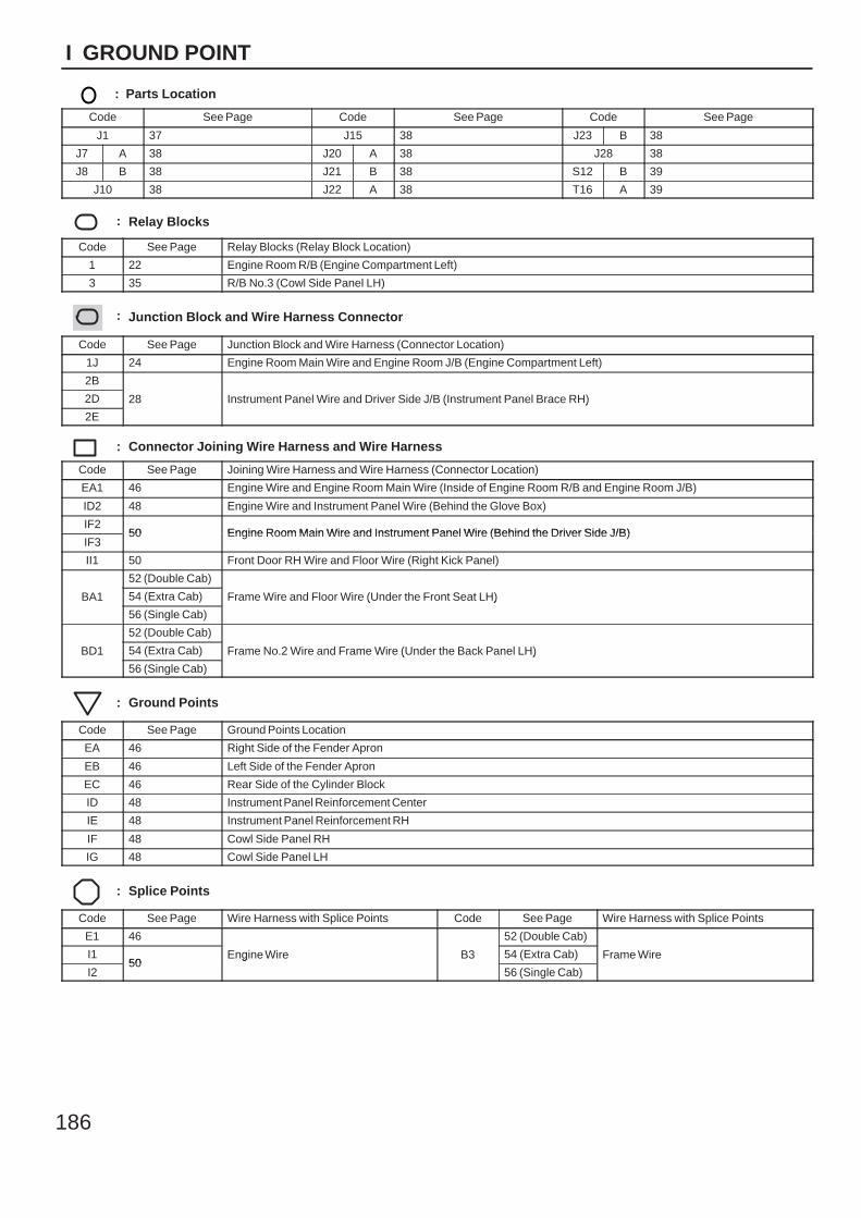
186
I GROUND POINT
: Parts Location
Code See Page Code See Page Code See Page
J1 37 J15 38 J23 B 38
J7 A 38 J20 A 38 J28 38
J8 B 38 J21 B 38 S12 B 39
J10 38 J22 A 38 T16 A 39
: Relay Blocks
Code See Page Relay Blocks (Relay Block Location)
1 22 Engine Room R/B (Engine Compartment Left)
3 35 R/B No.3 (Cowl Side Panel LH)
: Junction Block and Wire Harness Connector
Code See Page Junction Block and Wire Harness (Connector Location)
1J 24 Engine Room Main Wire and Engine Room J/B (Engine Compartment Left)
2B
28 Instrument Panel Wire and Driver Side J/B (Instrument Panel Brace RH)2D 28 Instrument Panel Wire and Driver Side J/B (Instrument Panel Brace RH)
2E
28 Instrument Panel Wire and Driver Side J/B (Instrument Panel Brace RH)
: Connector Joining Wire Harness and Wire Harness
Code See Page Joining Wire Harness and Wire Harness (Connector Location)
EA1 46 Engine Wire and Engine Room Main Wire (Inside of Engine Room R/B and Engine Room J/B)
ID2 48 Engine Wire and Instrument Panel Wire (Behind the Glove Box)
IF250 Engine Room Main Wire and Instrument Panel Wire (Behind the Driver Side J/B)
IF350 Engine Room Main Wire and Instrument Panel Wire (Behind the Driver Side J/B)
II1 50 Front Door RH Wire and Floor Wire (Right Kick Panel)
BA1
52 (Double Cab)
Frame Wire and Floor Wire (Under the Front Seat LH)BA1 54 (Extra Cab) Frame Wire and Floor Wire (Under the Front Seat LH)BA1
56 (Single Cab)
Frame Wire and Floor Wire (Under the Front Seat LH)
BD1
52 (Double Cab)
Frame No.2 Wire and Frame Wire (Under the Back Panel LH)BD1 54 (Extra Cab) Frame No.2 Wire and Frame Wire (Under the Back Panel LH)BD1
56 (Single Cab)
Frame No.2 Wire and Frame Wire (Under the Back Panel LH)
: Ground Points
Code See Page Ground Points Location
EA 46 Right Side of the Fender Apron
EB 46 Left Side of the Fender Apron
EC 46 Rear Side of the Cylinder Block
ID 48 Instrument Panel Reinforcement Center
IE 48 Instrument Panel Reinforcement RH
IF 48 Cowl Side Panel RH
IG 48 Cowl Side Panel LH
: Splice Points
Code See Page Wire Harness with Splice Points Code See Page Wire Harness with Splice Points
E1 46
Engine Wire B3
52 (Double Cab)
Frame WireI150
Engine Wire B3 54 (Extra Cab) Frame Wire
I250
Engine Wire B3
56 (Single Cab)
Frame Wire

187
Memo
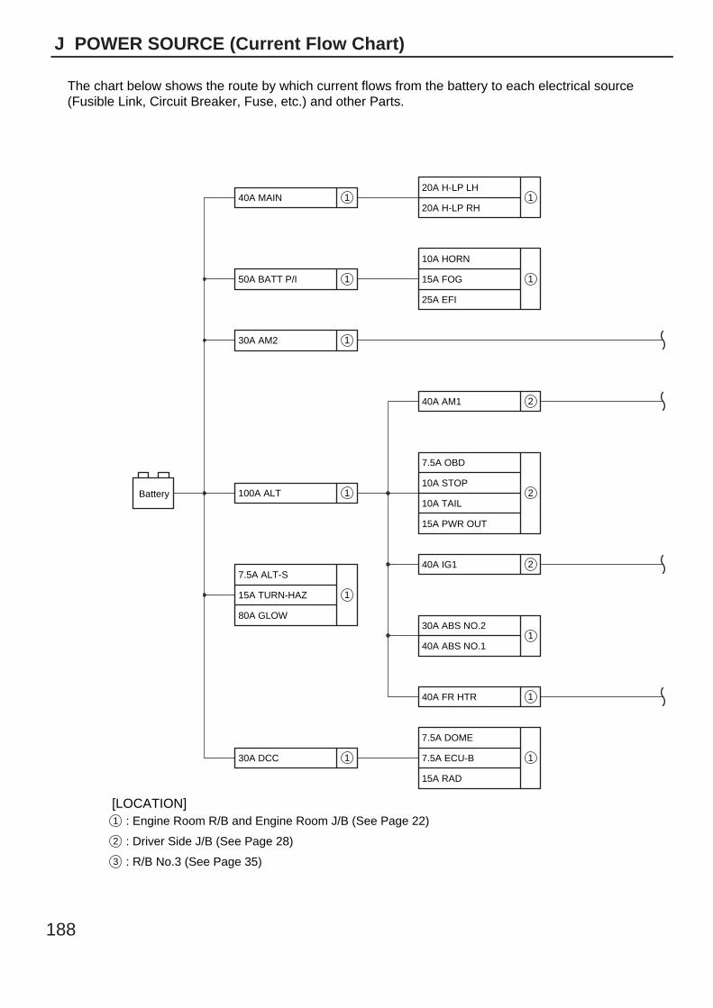
188
J POWER SOURCE (Current Flow Chart)
1 : Engine Room R/B and Engine Room J/B (See Page 22)
2 : Driver Side J/B (See Page 28)
3 : R/B No.3 (See Page 35)
The chart below shows the route by which current flows from the battery to each electrical source(Fusible Link, Circuit Breaker, Fuse, etc.) and other Parts.
[LOCATION]
Battery
40A MAIN20A H-LP LH
20A H-LP RH
10A HORN
15A FOG
25A EFI
40A AM1
7.5A OBD
10A STOP
10A TAIL
15A PWR OUT
40A IG1
30A ABS NO.2
40A ABS NO.1
40A FR HTR
7.5A DOME
7.5A ECU-B
15A RAD
50A BATT P/I
30A AM2
100A ALT
7.5A ALT-S
15A TURN-HAZ
80A GLOW
30A DCC
1
1
1
1
1
1
1
1 1
1
1
2
2
2
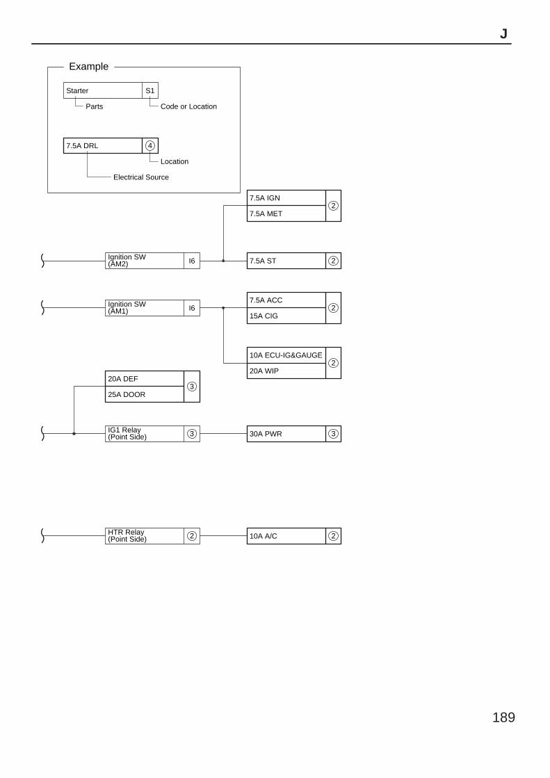
189
J
4
Code or LocationParts
Electrical Source
7.5A DRL
Starter S1
Location
Example
Ignition SW(AM2)
IG1 Relay(Point Side)
HTR Relay(Point Side)
Ignition SW(AM1)
I6
I6
20A DEF
7.5A IGN
7.5A MET
7.5A ST
7.5A ACC
15A CIG
10A ECU-IG&GAUGE
20A WIP
30A PWR
10A A/C
25A DOOR3
3
2
2
2
2
2
3
2
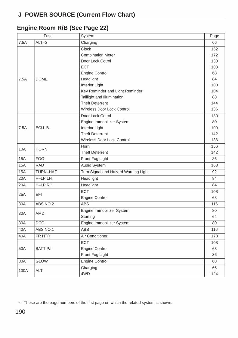
190
J POWER SOURCE (Current Flow Chart)
Engine Room R/B (See Page 22)Fuse System Page
7.5A ALT–S Charging 66
7.5A DOME
Clock
Combination Meter
Door Lock Cotrol
ECT
Engine Control
Headlight
Interior Light
Key Reminder and Light Reminder
Taillight and Illumination
Theft Deterrent
Wireless Door Lock Control
162
172
130
108
68
84
100
104
88
144
136
7.5A ECU–B
Door Lock Cotrol
Engine Immobilizer System
Interior Light
Theft Deterrent
Wireless Door Lock Control
130
80
100
142
136
10A HORNHorn
Theft Deterrent
156
142
15A FOG Front Fog Light 86
15A RAD Audio System 168
15A TURN–HAZ Turn Signal and Hazard Warning Light 92
20A H–LP LH Headlight 84
20A H–LP RH Headlight 84
25A EFIECT
Engine Control
108
68
30A ABS NO.2 ABS 116
30A AM2Engine Immobilizer System
Starting
80
64
30A DCC Engine Immobilizer System 80
40A ABS NO.1 ABS 116
40A FR HTR Air Conditioner 178
50A BATT P/I
ECT
Engine Control
Front Fog Light
108
68
86
80A GLOW Engine Control 68
100A ALTCharging
4WD
66
124
∗ These are the page numbers of the first page on which the related system is shown.
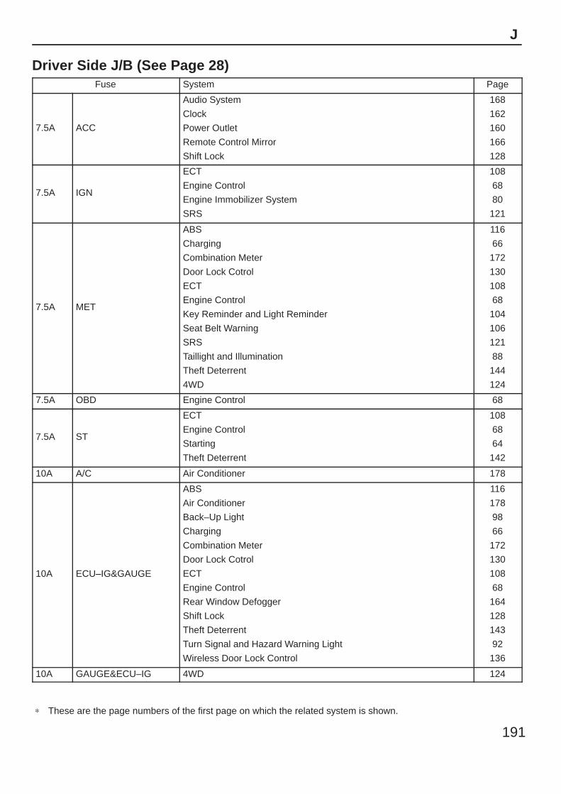
191
J
Driver Side J/B (See Page 28)Fuse System Page
7.5A ACC
Audio System
Clock
Power Outlet
Remote Control Mirror
Shift Lock
168
162
160
166
128
7.5A IGN
ECT
Engine Control
Engine Immobilizer System
SRS
108
68
80
121
7.5A MET
ABS
Charging
Combination Meter
Door Lock Cotrol
ECT
Engine Control
Key Reminder and Light Reminder
Seat Belt Warning
SRS
Taillight and Illumination
Theft Deterrent
4WD
116
66
172
130
108
68
104
106
121
88
144
124
7.5A OBD Engine Control 68
7.5A ST
ECT
Engine Control
Starting
Theft Deterrent
108
68
64
142
10A A/C Air Conditioner 178
10A ECU–IG&GAUGE
ABS
Air Conditioner
Back–Up Light
Charging
Combination Meter
Door Lock Cotrol
ECT
Engine Control
Rear Window Defogger
Shift Lock
Theft Deterrent
Turn Signal and Hazard Warning Light
Wireless Door Lock Control
116
178
98
66
172
130
108
68
164
128
143
92
136
10A GAUGE&ECU–IG 4WD 124
∗ These are the page numbers of the first page on which the related system is shown.
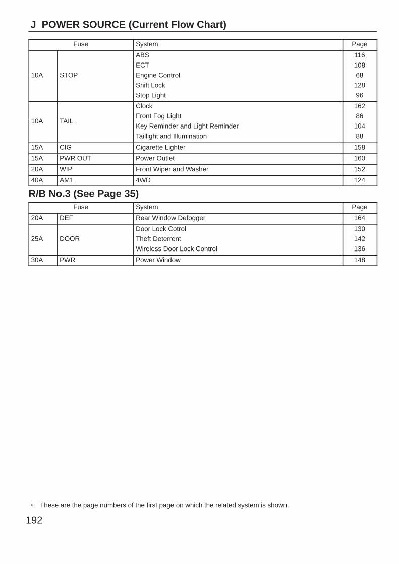
192
J POWER SOURCE (Current Flow Chart)
Fuse System Page
10A STOP
ABS
ECT
Engine Control
Shift Lock
Stop Light
116
108
68
128
96
10A TAIL
Clock
Front Fog Light
Key Reminder and Light Reminder
Taillight and Illumination
162
86
104
88
15A CIG Cigarette Lighter 158
15A PWR OUT Power Outlet 160
20A WIP Front Wiper and Washer 152
40A AM1 4WD 124
R/B No.3 (See Page 35)Fuse System Page
20A DEF Rear Window Defogger 164
25A DOOR
Door Lock Cotrol
Theft Deterrent
Wireless Door Lock Control
130
142
136
30A PWR Power Window 148
∗ These are the page numbers of the first page on which the related system is shown.

193
Memo
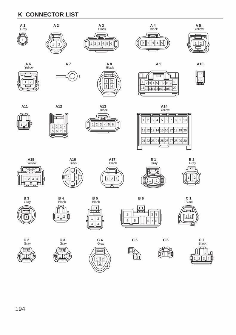
194
K CONNECTOR LIST
1
GrayA 1
1 2
A 2
1 2 3 4 5 6
BlackA 3
54321
BlackA 4
1 2
YellowA 5
1 2
YellowA 6
1
A 7
21
3 4
BlackA 8
1 2 3 4 5 6 7 8 9 10
11 1213141516171819 20
A 9
21
A10
1 2
A11
8765
431 2
A12
1 2 3 4 5 6
BlackA13
11
1 3 4 5 6 7 8 9
13 14 15 16 17 18 19
21 23 24 25 26 27 28 29 30
20
10
22
12
2
YellowA14
1 2 3 4
YellowA15
1 2
BlackA16
1 2 3
BlackA17
1 2
GrayB 1
1 2
GrayB 2
1
GrayB 3
1 2
BlackB 4
1 2
3 4
BlackB 5
1 2 3
4 5 6 7 8
B 6
1 2
BlackC 1
1 2
GrayC 2
1 2
GrayC 3
213
GrayC 4
1
2
C 5
1 2
C 6
1 2 3 4
BlackC 7
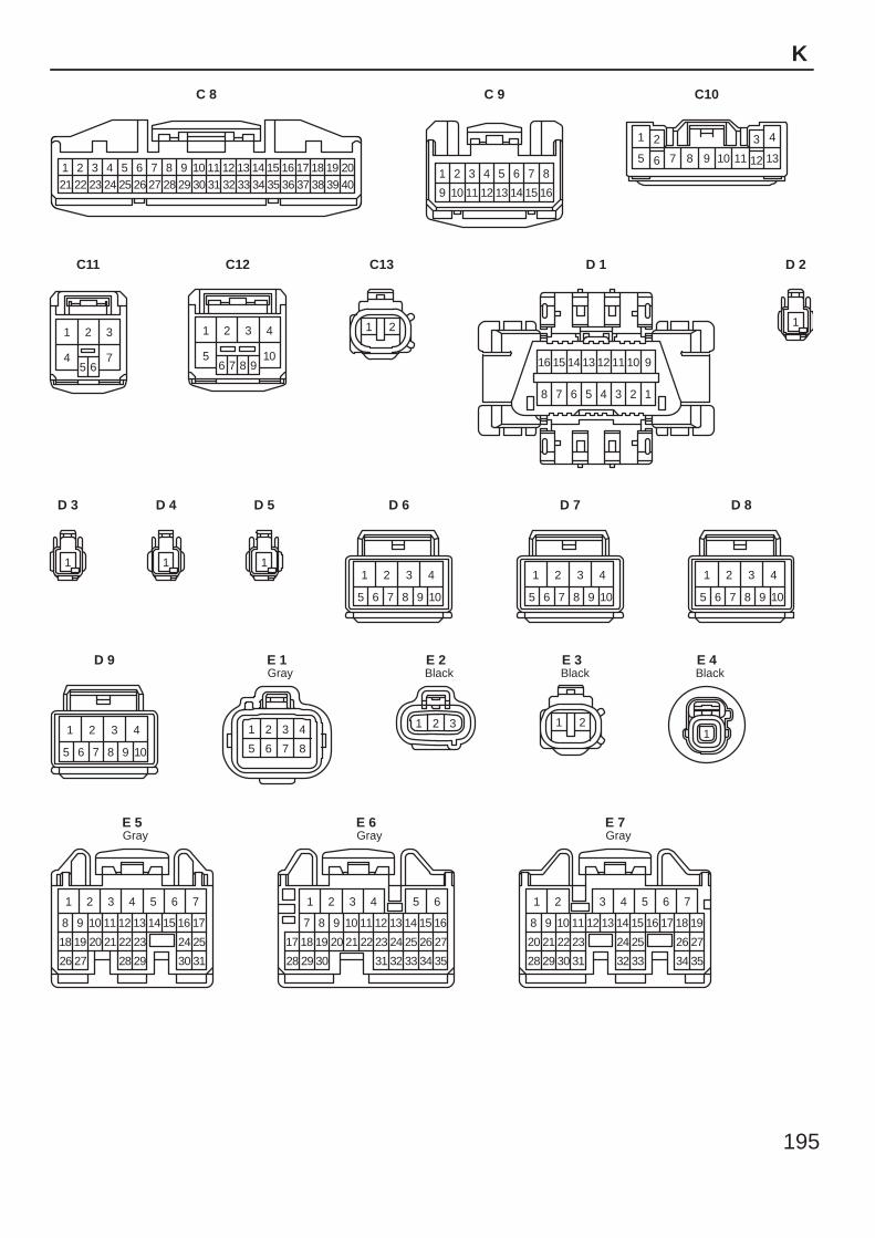
195
K
422
321 241
262362
277
288
3010
3111
3212
3313
3515
3616
3717
3818
2995
25 3414
3919
4020
C 8
9
1 2 3
16
4 5 86 7
10 11 151412 13
C 9
1 2 3 4
5 6 7 8 9 10 11 12 13
C10
1 2 3
45 6
7
C11
1 2 3 4
56 7 8 9
10
C12
1 2
C13
16 15 14 13 12 11 10 9
8 7 6 5 4 3 2 1
D 1
1
D 2
1
D 3
1
D 4
1
D 5
1 2 3 4
5 6 7 8 9 10
D 6
1 2 3 4
5 6 7 8 9 10
D 7
1 2 3 4
5 6 7 8 9 10
D 8
1 2 3 4
5 6 7 8 9 10
D 9
1 2 3 4
5 6 7 8
GrayE 1
1 2 3
BlackE 2
1 2
BlackE 3
1
BlackE 4
1
17
292827 31
19
9 10
30
11
76
13 14 15 16
22 23 24
12
432 5
25
26
18
8
20 21
GrayE 5
6
3228 35
24 27
13 1612
29
11
1
10987
2118
3 4 52
17
34
26
15
33
25
14
2322
31
2019
30
GrayE 6
1
19
333231 3528
2320
118 12
34
13
76
15 16 17 18
24 25 26
14
432 5
27
29
21
9
30
22
10
GrayE 7
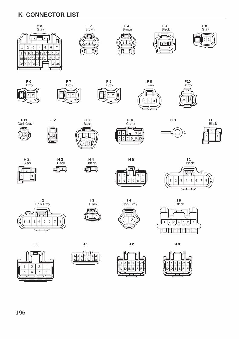
196
K CONNECTOR LIST
A A B B C C
D D E E F F
AAAAAA A A A A A A
A A B B C C
D D E E F F
1
3128
24 27
118 12
34
13
7
14 15 16 17
2118
542 6
29
26
9
30
25
10
2322
32
2019
33
3
GrayE 8
1 2
BrownF 2
1 2
BrownF 3
1 2
BlackF 4
1 2
GrayF 5
1 2
GrayF 6
1 2
GrayF 7
1 2
GrayF 8
1 2 3
BlackF 9
1 2
GrayF10
21
Dark GrayF11
1 2
F12
1 2 3
4 5
BlackF13
1 2 3 4
5 6 7 8 9 10
GreenF14
1
G 1
1
2 3
BlackH 1
1
2 3
BlackH 2
1
BlackH 3
1
BlackH 4
1 2
5
3 4
6 7 8 9 10
H 5
1 2 3 4 5 6 7 8
BlackI 1
87654321
Dark GrayI 2
1 2
BlackI 3
1 2
Dark GrayI 4
1 2 3 4 5 6 7
BlackI 5
1 2 3 4
5 6 7 8
I 6 J 1 J 2 J 3
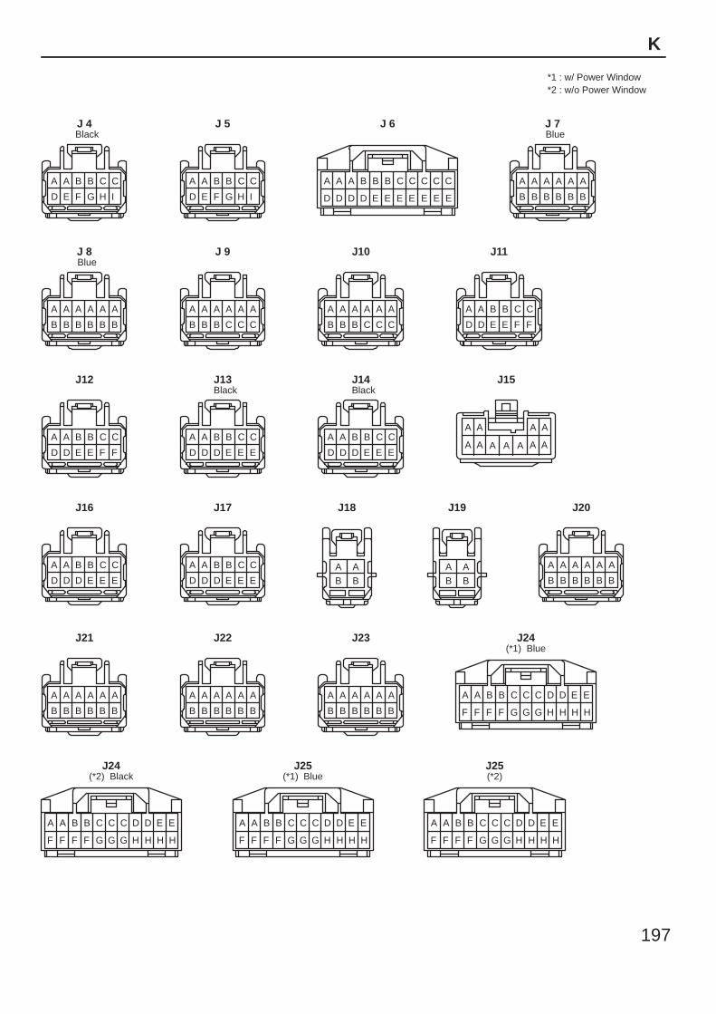
197
K
E
HH
ED
HH
DC
GG
CC
GF
BB
FF
A A
F
E
HH
ED
HH
DC
GG
CC
GF
BB
FF
A A
F
E
HH
ED
HH
DC
GG
CC
GF
BB
FF
A A
F
E
HH
ED
HH
DC
GG
CC
GF
BB
FF
A A
F
A A A A A A
B B B B B B
A A A A A A
B B B B B B
A A A A A A
B B B B B B
A A A A A A
B B B B B BA AB B
A A B B C C
D D D E E E
A A B B C C
D D D E E E
A A B B C C
D D D E E E
A A B B C C
D D D E E E
A A B B C C
D D E E F F
A A B B C C
D D E E F F
A A A A A A
B B B C C C
A A A A A A
B B B C C C
A A A A A A
B B B B B B
A A A A A A
B B B B B B
A A B B C C
D E F G H I
A A B B C C
D E F G H I
C
EE
CC
EE
CC
EE
BB
ED
BA
DD
A A
D
A A A A
A A A AA A A
A AB B
BlackJ 4 J 5 J 6
BlueJ 7
BlueJ 8 J 9 J10 J11
J12 BlackJ13
BlackJ14 J15
J16 J17 J18 J19 J20
J21 J22 J23(*1) Blue
J24
(*2) BlackJ24
(*1) BlueJ25
(*2)J25
*1 : w/ Power Window*2 : w/o Power Window
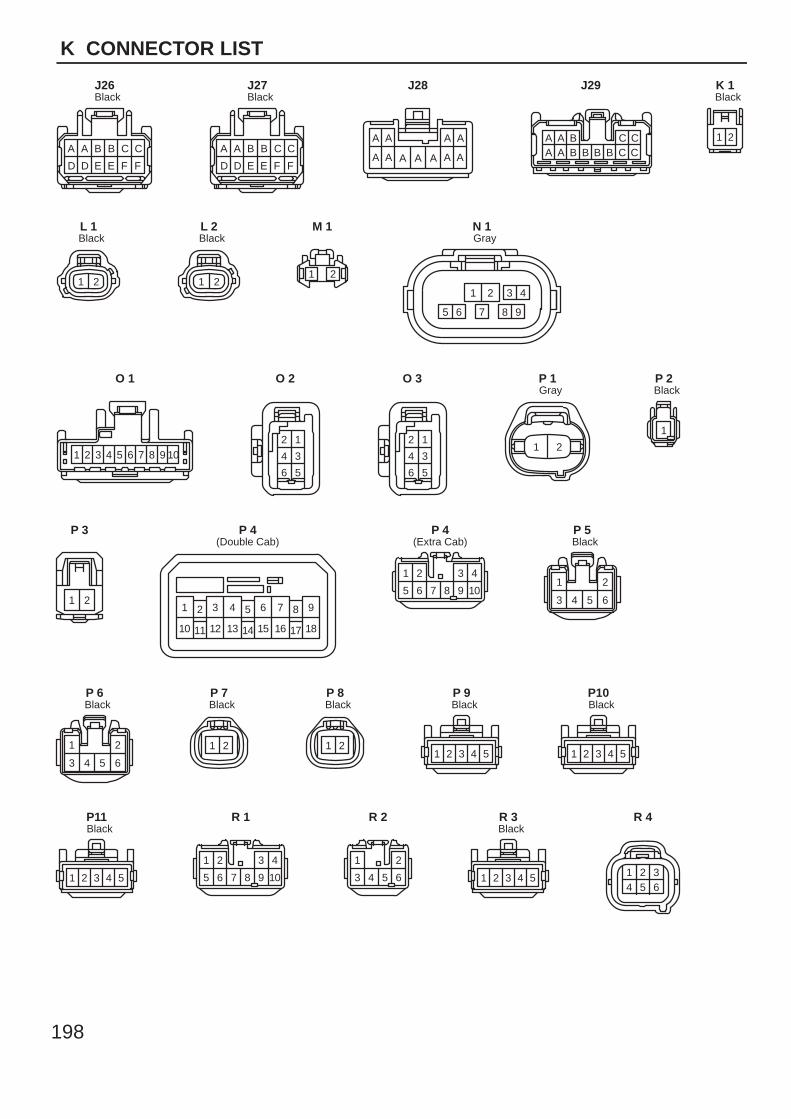
198
K CONNECTOR LIST
A A A A
A A A AA A AA A B B C C
D D E E F F
A A B B C C
D D E E F F
A A B C CA A B B B B C C
BlackJ26
BlackJ27 J28 J29
1 2
BlackK 1
1 2
BlackL 1
1 2
BlackL 2
1 2
M 1
87 9
21 3 4
65
GrayN 1
1 2 3 4 5 6 7 8 9 10
O 1
12
34
56
O 2
12
34
56
O 3
1 2
GrayP 1
1
BlackP 2
1 2
P 3
6 95 8
14
7
15
4
17
21
1816
3
11 1310 12
(Double Cab)P 4
1 2 3 4
5 6 7 8 9 10
(Extra Cab)P 4
1 2
3 4 5 6
BlackP 5
1 2
3 4 5 6
BlackP 6
1 2
BlackP 7
1 2
BlackP 8
1 2 3 4 5
BlackP 9
1 2 3 4 5
BlackP10
1 2 3 4 5
BlackP11
1 2 3 4
5 6 7 8 9 10
R 1
1 2
3 4 5 6
R 2
1 2 3 4 5
BlackR 3
1 2 34 5 6
R 4
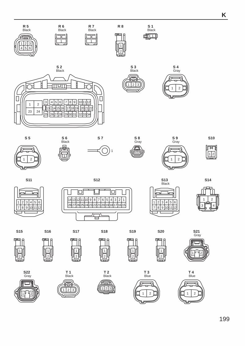
199
K
1 2 34 5 6
BlackR 5
1
BlackR 6
1
BlackR 7
1
2
R 8
1
BlackS 1
21
2423
3 4 5 6
13
25
161514
26 27 28 313029
17 18 19
987 10 11 12
222120
32 33 34
BlackS 2
1 2 3
BlackS 3
1 2
GrayS 4
1 2
S 5
1
BlackS 6
1
S 7
1 2
GrayS 8
1 2
GrayS 9
1 2
S10
7 8
1 2
12
4 5 6
9 1110
3
S11
10 9 8 7 6
23 2224 21 20
5
19
11
25
1
15
12
26
4
18
3
17
2
16
13
27
14
28
S12
7 8
1 2
12
4 5 6
9 1110
3
BlackS13
1
3
2
4
S14
1
2
S15
1
2
S16
1
2
S17
1
2
S18
1
2
S19
1
2
S20
1 2
GrayS21
1 2
GrayS22
1 2 3
BlackT 1
1 2 3
BlackT 2
1 2
BlueT 3
1 2
BlueT 4
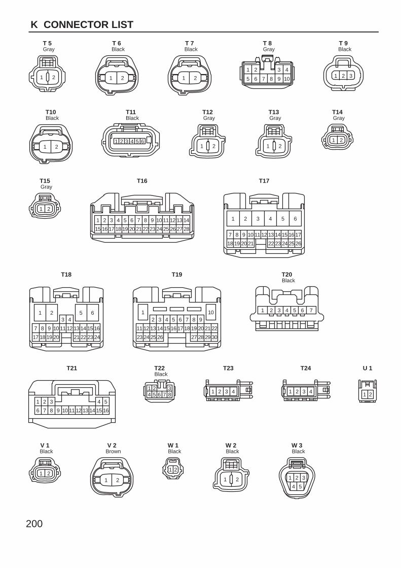
200
K CONNECTOR LIST
1 2
GrayT 5
1 2
BlackT 6
1 2
BlackT 7
1 2
5
3 4
6 7 8 9 10
GrayT 8
1 2 3
BlackT 9
1 2
BlackT10
1 2 3 4 5 6
BlackT11
1 2
GrayT12
1 2
GrayT13
1 2
GrayT14
1 2
GrayT15
21
15 16
4
18
5
19
6
20
7
21
8
22
9
23
10
24
11
25
13
27
14
28
3
17
12
26
T16
2322 2618
107
25
13 14 16 17
19
8
20
9 11 12 15
2421
1 2 3 4 5 6
T17
18 2417
87 9 10
23
4
11 12 15
3
1613 14
19 20 2221
1 2 5 6
T18
26 3023
1411
3 4
29
5 7 8 9
17 18 21
6
22
24
12
25
13
2
15 16 19 20
2827
1 10
T19
1 2 3 4 5 6 7
BlackT20
1
6
2
7
3
8 9 10 11 12 13 14
4
15
5
16
T21
1 2 34 5 6 7 8
BlackT22
1 2 3 4
T23
1 2 3 4
T24
1 2
U 1
1 2
BlackV 1
1 2
BrownV 2
21
BlackW 1
1 2
BlackW 2
1 2 3
4 5
BlackW 3

201
Memo
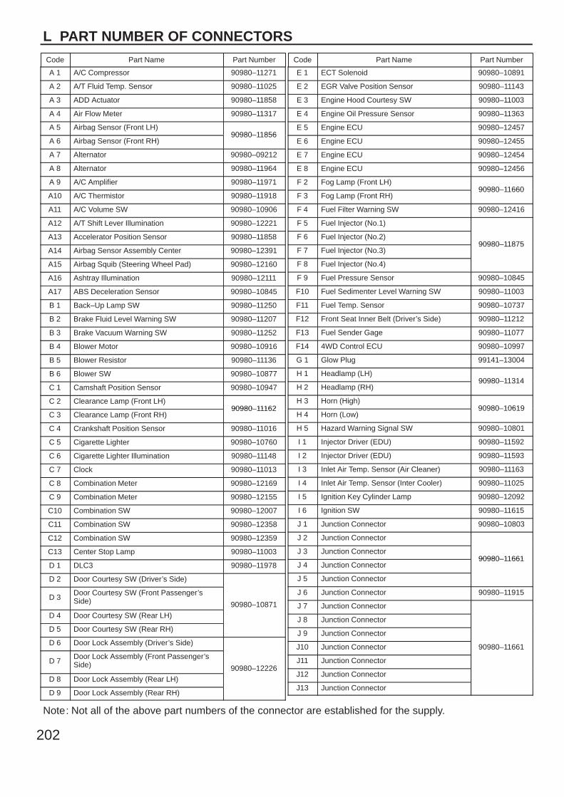
L PART NUMBER OF CONNECTORS
Code Part Name Part Number Code Part Name Part Number
Note: Not all of the above part numbers of the connector are established for the supply.
202
A 1 A/C Compressor 90980–11271
A 2 A/T Fluid Temp. Sensor 90980–11025
A 3 ADD Actuator 90980–11858
A 4 Air Flow Meter 90980–11317
A 5 Airbag Sensor (Front LH)90980–11856
A 6 Airbag Sensor (Front RH)90980–11856
A 7 Alternator 90980–09212
A 8 Alternator 90980–11964
A 9 A/C Amplifier 90980–11971
A10 A/C Thermistor 90980–11918
A11 A/C Volume SW 90980–10906
A12 A/T Shift Lever Illumination 90980–12221
A13 Accelerator Position Sensor 90980–11858
A14 Airbag Sensor Assembly Center 90980–12391
A15 Airbag Squib (Steering Wheel Pad) 90980–12160
A16 Ashtray Illumination 90980–12111
A17 ABS Deceleration Sensor 90980–10845
B 1 Back–Up Lamp SW 90980–11250
B 2 Brake Fluid Level Warning SW 90980–11207
B 3 Brake Vacuum Warning SW 90980–11252
B 4 Blower Motor 90980–10916
B 5 Blower Resistor 90980–11136
B 6 Blower SW 90980–10877
C 1 Camshaft Position Sensor 90980–10947
C 2 Clearance Lamp (Front LH)90980–11162
C 3 Clearance Lamp (Front RH)90980–11162
C 4 Crankshaft Position Sensor 90980–11016
C 5 Cigarette Lighter 90980–10760
C 6 Cigarette Lighter Illumination 90980–11148
C 7 Clock 90980–11013
C 8 Combination Meter 90980–12169
C 9 Combination Meter 90980–12155
C10 Combination SW 90980–12007
C11 Combination SW 90980–12358
C12 Combination SW 90980–12359
C13 Center Stop Lamp 90980–11003
D 1 DLC3 90980–11978
D 2 Door Courtesy SW (Driver’s Side)
90980–10871D 3
Door Courtesy SW (Front Passenger’sSide) 90980–10871
D 4 Door Courtesy SW (Rear LH)90980–10871
D 5 Door Courtesy SW (Rear RH)
D 6 Door Lock Assembly (Driver’s Side)
90980–12226D 7
Door Lock Assembly (Front Passenger’sSide) 90980–12226
D 8 Door Lock Assembly (Rear LH)90980–12226
D 9 Door Lock Assembly (Rear RH)
E 1 ECT Solenoid 90980–10891
E 2 EGR Valve Position Sensor 90980–11143
E 3 Engine Hood Courtesy SW 90980–11003
E 4 Engine Oil Pressure Sensor 90980–11363
E 5 Engine ECU 90980–12457
E 6 Engine ECU 90980–12455
E 7 Engine ECU 90980–12454
E 8 Engine ECU 90980–12456
F 2 Fog Lamp (Front LH)90980–11660
F 3 Fog Lamp (Front RH)90980–11660
F 4 Fuel Filter Warning SW 90980–12416
F 5 Fuel Injector (No.1)
90980–11875F 6 Fuel Injector (No.2)
90980–11875F 7 Fuel Injector (No.3)
90980–11875
F 8 Fuel Injector (No.4)
F 9 Fuel Pressure Sensor 90980–10845
F10 Fuel Sedimenter Level Warning SW 90980–11003
F11 Fuel Temp. Sensor 90980–10737
F12 Front Seat Inner Belt (Driver’s Side) 90980–11212
F13 Fuel Sender Gage 90980–11077
F14 4WD Control ECU 90980–10997
G 1 Glow Plug 99141–13004
H 1 Headlamp (LH)90980–11314
H 2 Headlamp (RH)90980–11314
H 3 Horn (High)90980–10619
H 4 Horn (Low)90980–10619
H 5 Hazard Warning Signal SW 90980–10801
I 1 Injector Driver (EDU) 90980–11592
I 2 Injector Driver (EDU) 90980–11593
I 3 Inlet Air Temp. Sensor (Air Cleaner) 90980–11163
I 4 Inlet Air Temp. Sensor (Inter Cooler) 90980–11025
I 5 Ignition Key Cylinder Lamp 90980–12092
I 6 Ignition SW 90980–11615
J 1 Junction Connector 90980–10803
J 2 Junction Connector
90980–11661J 3 Junction Connector
90980–11661J 4 Junction Connector
90980–11661
J 5 Junction Connector
J 6 Junction Connector 90980–11915
J 7 Junction Connector
90980–11661
J 8 Junction Connector
90980–11661
J 9 Junction Connector
90980–11661J10 Junction Connector 90980–11661
J11 Junction Connector
J12 Junction Connector
J13 Junction Connector
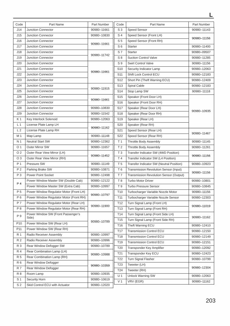
L
Code Part Name Part Number Code Part Name Part Number
203
J14 Junction Connector 90980–11661
J15 Junction Connector 90980–10830
J16 Junction Connector90980–11661
J17 Junction Connector90980–11661
J18 Junction Connector90980–11742
J19 Junction Connector90980–11742
J20 Junction Connector
90980–11661J21 Junction Connector
90980–11661J22 Junction Connector
90980–11661
J23 Junction Connector
J24 Junction Connector90980–11915
J25 Junction Connector90980–11915
J26 Junction Connector90980–11661
J27 Junction Connector90980–11661
J28 Junction Connector 90980–10830
J29 Junction Connector 90980–11542
K 1 Key Interlock Solenoid 90980–12063
L 1 License Plate Lamp LH90980–11162
L 2 License Plate Lamp RH90980–11162
M 1 Map Lamp 90980–11148
N 1 Neutral Start SW 90980–12362
O 1 Outer Mirror SW 90980–11657
O 2 Outer Rear View Mirror (LH)90980–11452
O 3 Outer Rear View Mirror (RH)90980–11452
P 1 Pressure SW 90980–11149
P 2 Parking Brake SW 90980–10871
P 3 Power Point Socket 90980–12498
P 4Power Window Master SW (Double Cab) 90980–12122
P 4Power Window Master SW (Extra Cab) 90980–10997
P 5 Power Window Regulator Motor (Front LH)90980–10797
P 6 Power Window Regulator Motor (Front RH)90980–10797
P 7 Power Window Regulator Motor (Rear LH)90980–11900
P 8 Power Window Regulator Motor (Rear RH)90980–11900
P 9Power Window SW (Front Passenger’sSide)
90980–10789P10 Power Window SW (Rear LH)
90980–10789
P11 Power Window SW (Rear RH)
R 1 Radio Receiver Assembly 90980–10997
R 2 Radio Receiver Assembly 90980–10996
R 3 Rear Window Defogger SW 90980–10789
R 4 Rear Combination Lamp (LH)90980–10988
R 5 Rear Combination Lamp (RH)90980–10988
R 6 Rear Window Defogger90980–10359
R 7 Rear Window Defogger90980–10359
R 8 Room Lamp 90980–10935
S 1 Security Horn 90980–10619
S 2 Skid Control ECU with Actuator 90980–12020
S 3 Speed Sensor 90980–11143
S 4 Speed Sensor (Front LH)90980–11156
S 5 Speed Sensor (Front RH)90980–11156
S 6 Starter 90980–11400
S 7 Starter 90980–09507
S 8 Suction Control Valve 90980–11285
S 9 Swirl Control Valve 90980–11156
S10 Security Indicator Lamp 90980–12063
S11 Shift Lock Control ECU 90980–12183
S12 Short Pin (Theft Warning ECU) 90980–12409
S13 Spiral Cable 90980–12183
S14 Stop Lamp SW 90980–11118
S15 Speaker (Front Door LH)
90980–10935
S16 Speaker (Front Door RH)
90980–10935S17 Speaker (Rear Door LH)
90980–10935S18 Speaker (Rear Door RH)
90980–10935
S19 Speaker (Rear LH)
S20 Speaker (Rear RH)
S21 Speed Sensor (Rear LH)90980–11467
S22 Speed Sensor (Rear RH)90980–11467
T 1 Throttle Body Assembly 90980–11145
T 2 Throttle Body Assembly 90980–11261
T 3 Transfer Indicator SW (4WD Position)90980–11156
T 4 Transfer Indicator SW (L4 Position)90980–11156
T 5 Transfer Indicator SW (Neutral Position) 90980–10923
T 6 Transmission Revolution Sensor (Input)90980–11156
T 7 Transmission Revolution Sensor (Output)90980–11156
T 8 Turbo Motor Driver 90980–10801
T 9 Turbo Pressure Sensor 90980–10845
T10 Turbocharger Variable Nozzle Motor 90980–11156
T11 Turbocharger Variable Nozzle Sensor 90980–12303
T12 Turn Signal Lamp (Front LH)90980–11019
T13 Turn Signal Lamp (Front RH)90980–11019
T14 Turn Signal Lamp (Front Side LH)90980–11162
T15 Turn Signal Lamp (Front Side RH)90980–11162
T16 Theft Warning ECU 90980–12410
T17 Transmission Control ECU 90980–12150
T18 Transmission Control ECU 90980–12149
T19 Transmission Control ECU 90980–12151
T20 Transponder Key Amplifier 90980–12092
T21 Transponder Key ECU 90980–12423
T22 Turn Signal Flasher 90980–10799
T23 Tweeter (LH)90980–12304
T24 Tweeter (RH)90980–12304
U 1 Unlock Warning SW 90980–12063
V 1 VRV (EGR) 90980–11162
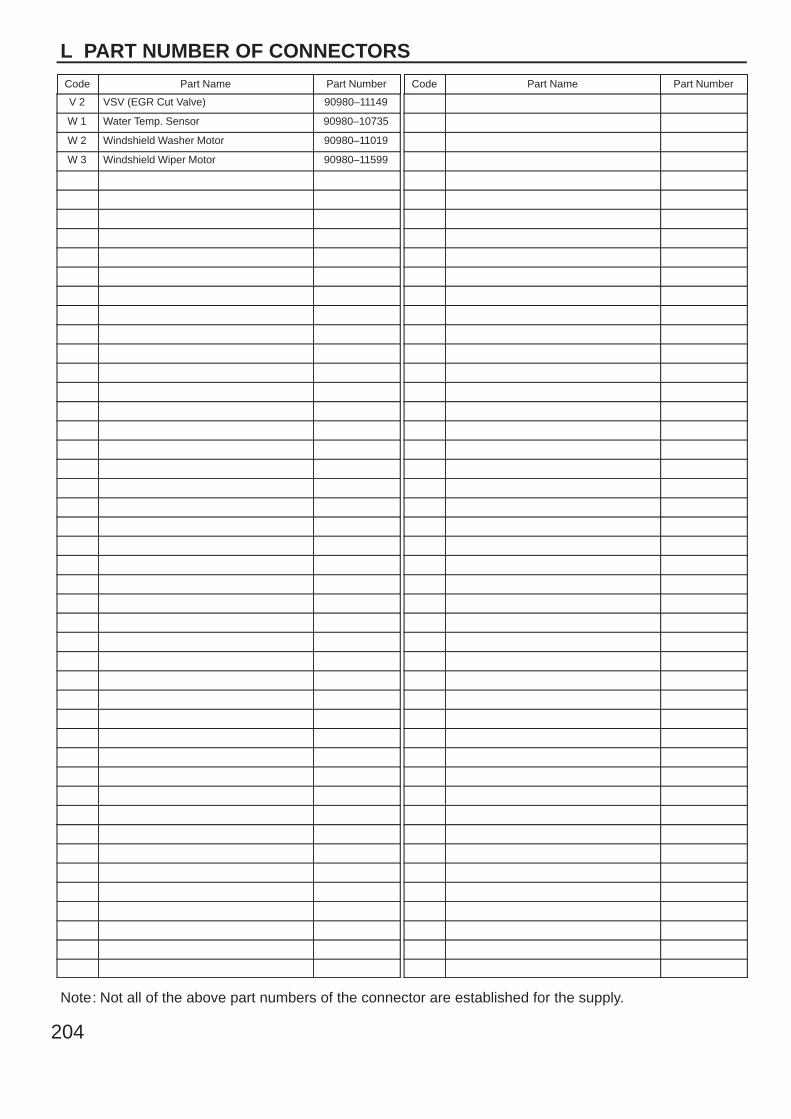
L PART NUMBER OF CONNECTORS
Code Part Name Part Number Code Part Name Part Number
Note: Not all of the above part numbers of the connector are established for the supply.
204
V 2 VSV (EGR Cut Valve) 90980–11149
W 1 Water Temp. Sensor 90980–10735
W 2 Windshield Washer Motor 90980–11019
W 3 Windshield Wiper Motor 90980–11599

L
Code Part Name Part Number Code Part Name Part Number
205
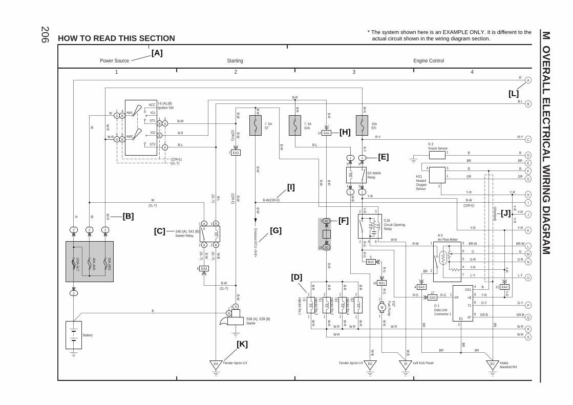
2
4
1 2 3 4
HOW TO READ THIS SECTION
ACC
IG1
ST1
IG2
ST2
AM2
6 EA4
7 EA3
2 A 2 B
1 A 1 B
4B
5A
B
1B
EA
1
3C15
3C7
41 6
1
1
1
3
2 3
1
2
4 3
1
1
3
6
5
4
7
4 EA3
12 EA1
BO25
21 EA3
ID ECEA
1
2
1
2
1
2
1
2
16 BS1
1
2
M
EA317 1
4
8
6
9B
W
W-R
B-W
B-R
B-L B-L
B-W(22R-E)
B-W
W-R
R-G
B
BR
B
GR
Y-R
B-W
Y-R
BR-W
G
G-R
Y-R
L-Y
Y-R
G-Y
GR-B
W-BR-W
R-G
BR
W-R
W-R
Y-R
R-Y
B-W
Y-R
Y-R
W
B-R
WR W-R
W-R
W
B-L
B-W
B-W
B-W
B-R
B-R
B-R
B-R
B-R
B-R
W-R
W-R
W-R
W-R B
R
BR
W-B
W-B
R-G
Y-R
W-B
B-R
Y-R
B
Y-R
W-B
B-W
W-B
B-R
R-Y
W-R
B-W
BR
100A A
LT
40A A
M1
30A A
M2
4A
2A
1A
7
(22R-E)(2L-T)
7. 5AST
7. 5AIGN
B-W
R-G
15AEFI
R-G
FP
OX1
+B
T1
VF
B-L
(2L-T)
1 A1B
R
AM1
B-W
2
BR
E1
3
(2L-T)
(22R-E
)
(2L-T)
(2L-T)
B-W
R-G
Y-R
Y-R
Y-R
W-R W-R
B
8B
A
B
C
D
E
F
G
H
I
K
L
M
N
O
P
Q
R
S
J
1
R-Y
B
BR
GR
(22R-E)
BR-W
G
G-R
L-Y
GR-B
G-Y
W-R
(2L-T)
BR
(22R-E
)
* The system shown here is an EXAMPLE ONLY. It is different to the actual circuit shown in the wiring diagram section.
[A]
[B]
[C]
[D]
[E]
[G][F]
[H]
[I]
[J]
[K]
[L]
C19
A 5
H11
K 2
I 9 I11
I10
I12 F37 D 1
I 6 (A),(B)
S40 (A), S41 (B)
S38 (A), S39 (B)
2
2 2 2
B-W
Fender Apron LH
(Shielded)
EFI MAINRelay
Fender Apron LH Left Kick Panel
Starting
IntakeManifold RH
Power Source Engine Control
Circuit OpeningRelay
Air Flow Meter
HeatedOxygenSensor
Knock Sensor
Injector No.1
Injector No.3
Injector No.2
Injector No.4
Fuel Pum
p
Data LinkConnector 1
Ignition SW
Starter Relay
Starter
Battery
Em
ission EC
U <9-8>
206
M O
VE
RA
LL
EL
EC
TR
ICA
L W
IRIN
G D
IAG
RA
M
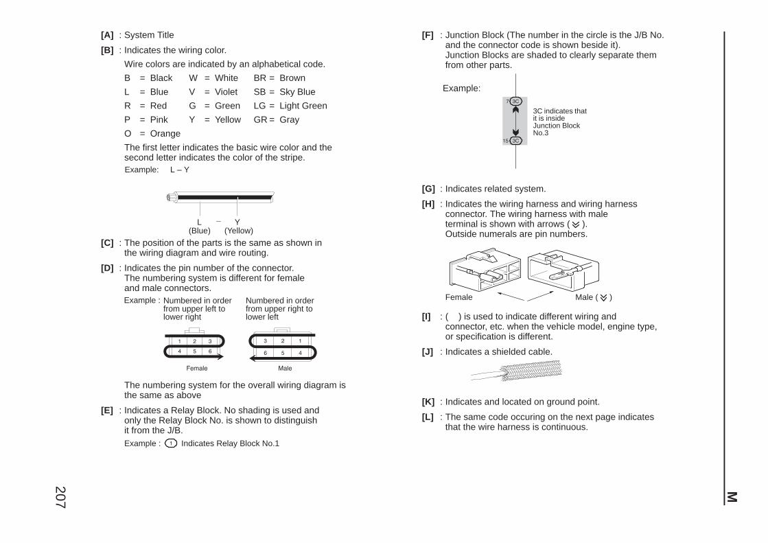
207
[A] : System Title
[B] : Indicates the wiring color.
Wire colors are indicated by an alphabetical code.
B = Black W = White BR = Brown
L = Blue V = Violet SB = Sky Blue
R = Red G = Green LG = Light Green
P = Pink Y = Yellow GR = Gray
O = Orange
The first letter indicates the basic wire color and thesecond letter indicates the color of the stripe.Example: L – Y
L(Blue)
Y(Yellow)
[C] : The position of the parts is the same as shown inthe wiring diagram and wire routing.
[D] : Indicates the pin number of the connector.The numbering system is different for femaleand male connectors.Example : Numbered in order
from upper left tolower right
Numbered in orderfrom upper right tolower left
The numbering system for the overall wiring diagram is the same as above
[E] : Indicates a Relay Block. No shading is used and only the Relay Block No. is shown to distinguishit from the J/B.Example : Indicates Relay Block No.1
[F] : Junction Block (The number in the circle is the J/B No. and the connector code is shown beside it). Junction Blocks are shaded to clearly separate them from other parts.
3C indicates thatit is insideJunction BlockNo.3
Example:
[G] : Indicates related system.
[H] : Indicates the wiring harness and wiring harnessconnector. The wiring harness with maleterminal is shown with arrows ( ).Outside numerals are pin numbers.
Female Male ( )
[I] : ( ) is used to indicate different wiring andconnector, etc. when the vehicle model, engine type, or specification is different.
[J] : Indicates a shielded cable.
[K] : Indicates and located on ground point.
[L] : The same code occuring on the next page indicates that the wire harness is continuous.
M
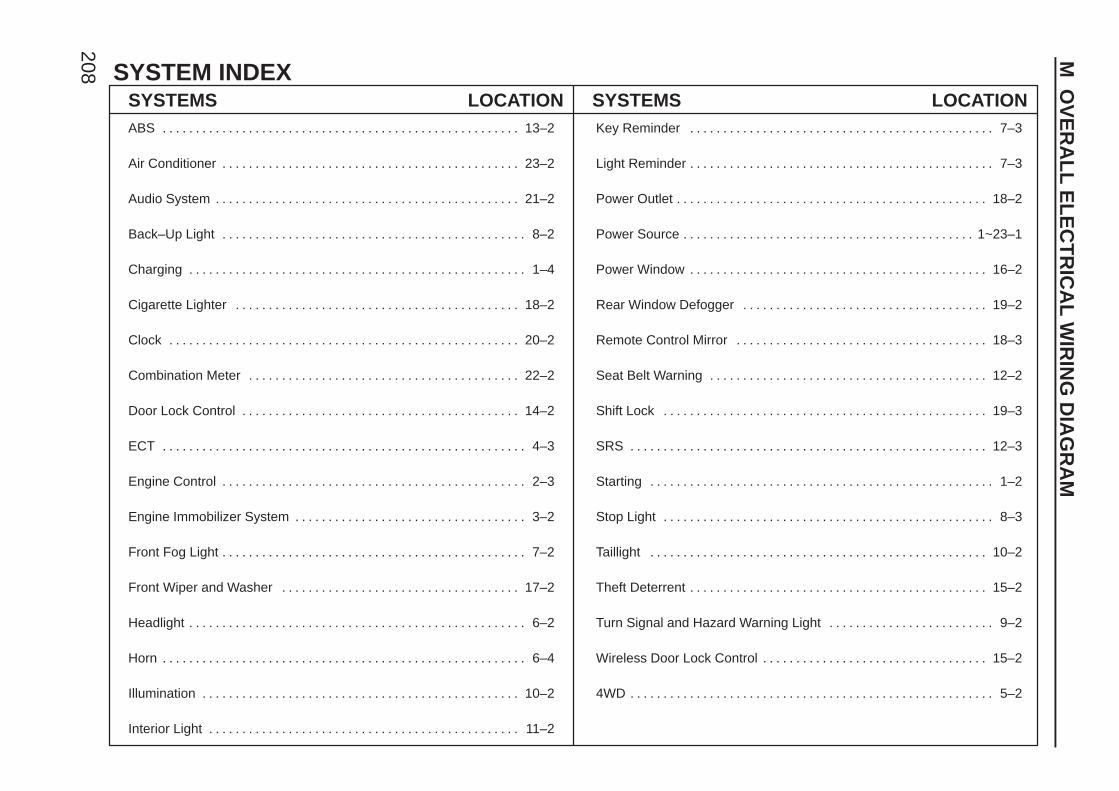
SYSTEM INDEX
208
SYSTEMS LOCATION SYSTEMS LOCATIONABS 13–2. . . . . . . . . . . . . . . . . . . . . . . . . . . . . . . . . . . . . . . . . . . . . . . . . . . . . .
Air Conditioner 23–2. . . . . . . . . . . . . . . . . . . . . . . . . . . . . . . . . . . . . . . . . . . . .
Audio System 21–2. . . . . . . . . . . . . . . . . . . . . . . . . . . . . . . . . . . . . . . . . . . . . .
Back–Up Light 8–2. . . . . . . . . . . . . . . . . . . . . . . . . . . . . . . . . . . . . . . . . . . . . .
Charging 1–4. . . . . . . . . . . . . . . . . . . . . . . . . . . . . . . . . . . . . . . . . . . . . . . . . . .
Cigarette Lighter 18–2. . . . . . . . . . . . . . . . . . . . . . . . . . . . . . . . . . . . . . . . . . .
Clock 20–2. . . . . . . . . . . . . . . . . . . . . . . . . . . . . . . . . . . . . . . . . . . . . . . . . . . . .
Combination Meter 22–2. . . . . . . . . . . . . . . . . . . . . . . . . . . . . . . . . . . . . . . . .
Door Lock Control 14–2. . . . . . . . . . . . . . . . . . . . . . . . . . . . . . . . . . . . . . . . . .
ECT 4–3. . . . . . . . . . . . . . . . . . . . . . . . . . . . . . . . . . . . . . . . . . . . . . . . . . . . . . .
Engine Control 2–3. . . . . . . . . . . . . . . . . . . . . . . . . . . . . . . . . . . . . . . . . . . . . .
Engine Immobilizer System 3–2. . . . . . . . . . . . . . . . . . . . . . . . . . . . . . . . . . .
Front Fog Light 7–2. . . . . . . . . . . . . . . . . . . . . . . . . . . . . . . . . . . . . . . . . . . . . .
Front Wiper and Washer 17–2. . . . . . . . . . . . . . . . . . . . . . . . . . . . . . . . . . . .
Headlight 6–2. . . . . . . . . . . . . . . . . . . . . . . . . . . . . . . . . . . . . . . . . . . . . . . . . . .
Horn 6–4. . . . . . . . . . . . . . . . . . . . . . . . . . . . . . . . . . . . . . . . . . . . . . . . . . . . . . .
Illumination 10–2. . . . . . . . . . . . . . . . . . . . . . . . . . . . . . . . . . . . . . . . . . . . . . . .
Interior Light 11–2. . . . . . . . . . . . . . . . . . . . . . . . . . . . . . . . . . . . . . . . . . . . . . .
Key Reminder 7–3. . . . . . . . . . . . . . . . . . . . . . . . . . . . . . . . . . . . . . . . . . . . . .
Light Reminder 7–3. . . . . . . . . . . . . . . . . . . . . . . . . . . . . . . . . . . . . . . . . . . . . .
Power Outlet 18–2. . . . . . . . . . . . . . . . . . . . . . . . . . . . . . . . . . . . . . . . . . . . . . .
Power Source 1~23–1. . . . . . . . . . . . . . . . . . . . . . . . . . . . . . . . . . . . . . . . . . . .
Power Window 16–2. . . . . . . . . . . . . . . . . . . . . . . . . . . . . . . . . . . . . . . . . . . . .
Rear Window Defogger 19–2. . . . . . . . . . . . . . . . . . . . . . . . . . . . . . . . . . . . .
Remote Control Mirror 18–3. . . . . . . . . . . . . . . . . . . . . . . . . . . . . . . . . . . . . .
Seat Belt Warning 12–2. . . . . . . . . . . . . . . . . . . . . . . . . . . . . . . . . . . . . . . . . .
Shift Lock 19–3. . . . . . . . . . . . . . . . . . . . . . . . . . . . . . . . . . . . . . . . . . . . . . . . .
SRS 12–3. . . . . . . . . . . . . . . . . . . . . . . . . . . . . . . . . . . . . . . . . . . . . . . . . . . . . .
Starting 1–2. . . . . . . . . . . . . . . . . . . . . . . . . . . . . . . . . . . . . . . . . . . . . . . . . . . .
Stop Light 8–3. . . . . . . . . . . . . . . . . . . . . . . . . . . . . . . . . . . . . . . . . . . . . . . . . .
Taillight 10–2. . . . . . . . . . . . . . . . . . . . . . . . . . . . . . . . . . . . . . . . . . . . . . . . . . .
Theft Deterrent 15–2. . . . . . . . . . . . . . . . . . . . . . . . . . . . . . . . . . . . . . . . . . . . .
Turn Signal and Hazard Warning Light 9–2. . . . . . . . . . . . . . . . . . . . . . . . .
Wireless Door Lock Control 15–2. . . . . . . . . . . . . . . . . . . . . . . . . . . . . . . . . .
4WD 5–2. . . . . . . . . . . . . . . . . . . . . . . . . . . . . . . . . . . . . . . . . . . . . . . . . . . . . . .
M O
VE
RA
LL
EL
EC
TR
ICA
L W
IRIN
G D
IAG
RA
M
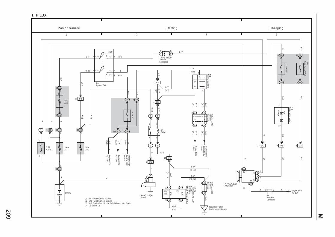
209 M
3 421
1 HILUX
5
4
P
N
1
2
3
5
1 A1B
B–Y
B–Y
(A/T )
1
1 A
B B1
B
B
S
L
IG
C h a rg in gS ta r tin gP o w e r S o u rc e
ID2
W
B–O
B W GR
R–L
GR
4
2
LL
7
6
B–W
7. 5A S
T
2C
7. 5A M
ET
B–Y
10AE
CU
–IG&
GA
UG
E
AM2 6
2A1AM1
ST2
B–R
2 2A
1
2
1 2G
IG2
IG1
ACC
5
4
W–R
32 2S
B
40AAM1
Battery
1 1F
B–YB–R
B
R–L
W–R
100AALT
1A1
W
30AAM2
4 1B
W–R
I 6
6B
2C
7 B–W
B
1 1E
W
1
7. 5AALT–S
2
1
W–R
2N192O19
2D1
2O3
L–YE
ngine EC
U<
2–10>
(A/T )
L–YTransm
issionC
ontrol EC
U<
4–4>
S 6(A), S 7(B)
BA
BB
J18(A), J19(B)
B–Y
1 1
1 1
STRelay
2 EA2
10 IF3
12 A 1 A
12 B 1 B
B A
B B
ID Instrument PanelReinforcement Center
W–B
W–B
W–B
W–B
S12 (B )
J22 (A ), J23 (B )
T16 (A )(∗4 )
(∗4 )
(∗4)
SRLY(∗1)
E(∗1)
L–Y
L–Y N 1
4 EA1
L–Y(M
/T )
(M/T )
D A D A
F B F B
B–Y
Engine E
CU
<2–10>
(A/T )
B–Y
Transmission
Control E
CU
<4–4>
(A/T )
J11 (A ), J12 (B )
13 EA1 4 ID2 3 ID2
Charge
C 8
37
21
A 7(A), A 8(B) 3 B
M
B BG G
J 6
Engine ECU<2–10>
∗ 1 : w/ Theft Deterrent System∗ 2 : w/o Theft Deterrent System
B
(A/T)L–Y
(A/T)L–Y
W–R
11 IF3
B–Y
(A/T )
Alternator
Com
bination Meter
Ignition SW
JunctionConnector
JunctionC
onnector
JunctionConnector
JunctionC
onnectorN
eutral Start S
W
Starter
Short P
in(Theft W
arning EC
U)
B L
∗ 3 : M/T Single Cab, Double Cab 2KD w/o Inter Cooler
L–YE
ngine EC
U<
2–10>(A
/T )
B–W
B–W
∗ 4 : ∗2 Except ∗3
(∗1, ∗4 )(∗2 ∗3)
(∗1, ∗4)
Theft Warning E
CU
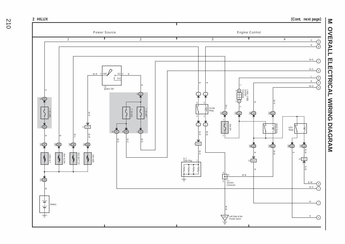
210
M O
VE
RA
LL
EL
EC
TR
ICA
L W
IRIN
G D
IAG
RA
M
1 2 3 4
2 HILUX (Cont. next page)
P o w e r S o u rc e
Battery
BW–R
100A A
LT
1A1
W
1F1
B
W–L
1B3
50A B
ATT P
/I
30A A
M2
4 1B
W–R
W–R
5 IG2
ST2
6AM2
7. 5A IG
N
2C
7. 5A M
ET
B
6
1J 1J
1J 1J
MA
IN R
elayW
–GW
–B
B
O
14 2D
2G1
I 6
W–B
EB Left Side of theFender Apron
E n g in e C o n tro l
B
B–W
B–W
7. 5A O
BD
5 3
4 2
2S22 2D1
B–O
B–O
B–O
O
B–O
2M6
B–O
B–O
1
2
1 1H
W–L
25A E
FI
L
1J1
J 4 (A ), J 5 (B )
A B
C A
L
L
12 EA1
B
A
A
W–G
B
R
12 IF2
1J8 1J7
B
B–W
11 IF3
B
H
G
J
C
A
D
F
I
E
B
B
1G1
80A G
LOW
EDURelay
1
2
3
5
1 1
1 1
GLOWRelay
B–R
W–B
B R
1 EA2
1G 1
W–B
B–R
BK
J 1
A
Glow Plug
Ignition SW
JunctionConnector
JunctionC
onnector
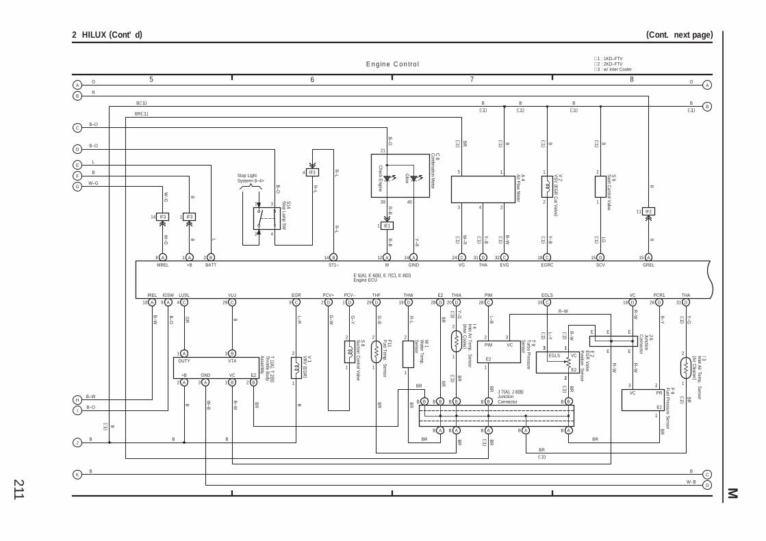
211 M
5 6 7 8
2 HILUX (Cont' d) (Cont. next page)
E n g in e C o n tro l
IGSW
A9
B–O
R
R–B
Check E
ngine
BB
IE11
B
R–W
A
GIND
B–WH B
R
40
Y–R
L
W 1
1
2
R
Y–G
BR
THIA
D20
W–GG
JB
OA
21
B–O
R–B
39
C 8
CB–O
2
1
Glow
LUSL
GR
4
D
C29
B
VLU
C
B
9 C
EGR
2
L–R
1
GREL
A15
R
W
A12
OA
ST1–
14 B
4
3
4 IF3
DB–O
BF
R–L
B–O
R–L
S14
IF3
B
W–G
14
B
W–G
+BMREL
1 AA8
19
R–L
14B2
BATT
B–W
IREL
A10 D
THW
BR
R–L
IB–O
1 IF3
L
E 5(A), E 6(B), E 7(C), E 8(D)
2
1
I 4
1
2
E
S 8
W–B
29 D
THF
BR
G–B
W–B
B
2
1
Stop LightSystem<8–4>
IF211
B B B B
B A B A
BR
BR
E2
D28
B B
BR
PCR1
B B
B A
PIM
L–B
28 C
T 9
2
1
BR
VC
R–W
18 D
E2
PIME E
E
R–W
R–Y
26 D
F 9
2
1
BR
3
E2
PR
R–W
VC
BR BR
CB
KB
2 D 1 D
PCV–PCV+
G–Y
G–W
18 C 15 D24 C 31 D 32 C
V 1
B A
I 3
Y–G
BR
(∗2 )
(∗2)
2
1
THA
BR
(∗2 )
(∗3 )
1 21
2 13 4 2
EGRC SCVVG THA EVGB
–W
Y–B
W–R
LG
Y–B
B BB
B
BB BB(∗1)
V 2
S 9
B A
BR
BR
(∗1 )
(∗1 )
(∗1 )
(∗1 )
(∗1 )(∗1 )
(∗1 )
(∗1 )
(∗1 )
(∗1)(∗1) (∗1)BR(∗1)
A 4
∗ 1 : 1KD–FTV∗ 2 : 2KD–FTV∗ 3 : w/ Inter Cooler
5
(∗1 )
(∗1 )
BB
(∗1)
31 D
BR
F11
Air Flow
Meter
Com
bination Meter
Engine ECU
Fuel Pressure S
ensor
Fuel Temp. S
ensor
Suction C
ontrol Valve
Stop Lam
p SW
Turbo Pressure
Sensor
VR
V (E
GR
)
Water Tem
p. S
ensor
J 7(A), J 8(B)JunctionConnector
(∗3 )
Inlet Air Tem
p. Sensor
(Inter Cooler )
Inlet Air Tem
p. Sensor
(Air C
leaner )
VS
V (E
GR
Cut V
alve )
Sw
irl Control V
alve
VC
VTA
+B
DUTY
E2GND
1 A 3 B
2 A 3 A 1 B 2 B
Throttle Body
Assem
bly
T 1 (A ), T 2 (B )
3
VC
R–W
B B
EGLS
33 C
3 1
2
L–Y(∗2 )
R–W
(∗2 )B
R(∗2 )
JunctionC
onnector
J 6
EE
E 2E
GR
Valve
Position S
ensor2
13
EGLS VC
E2
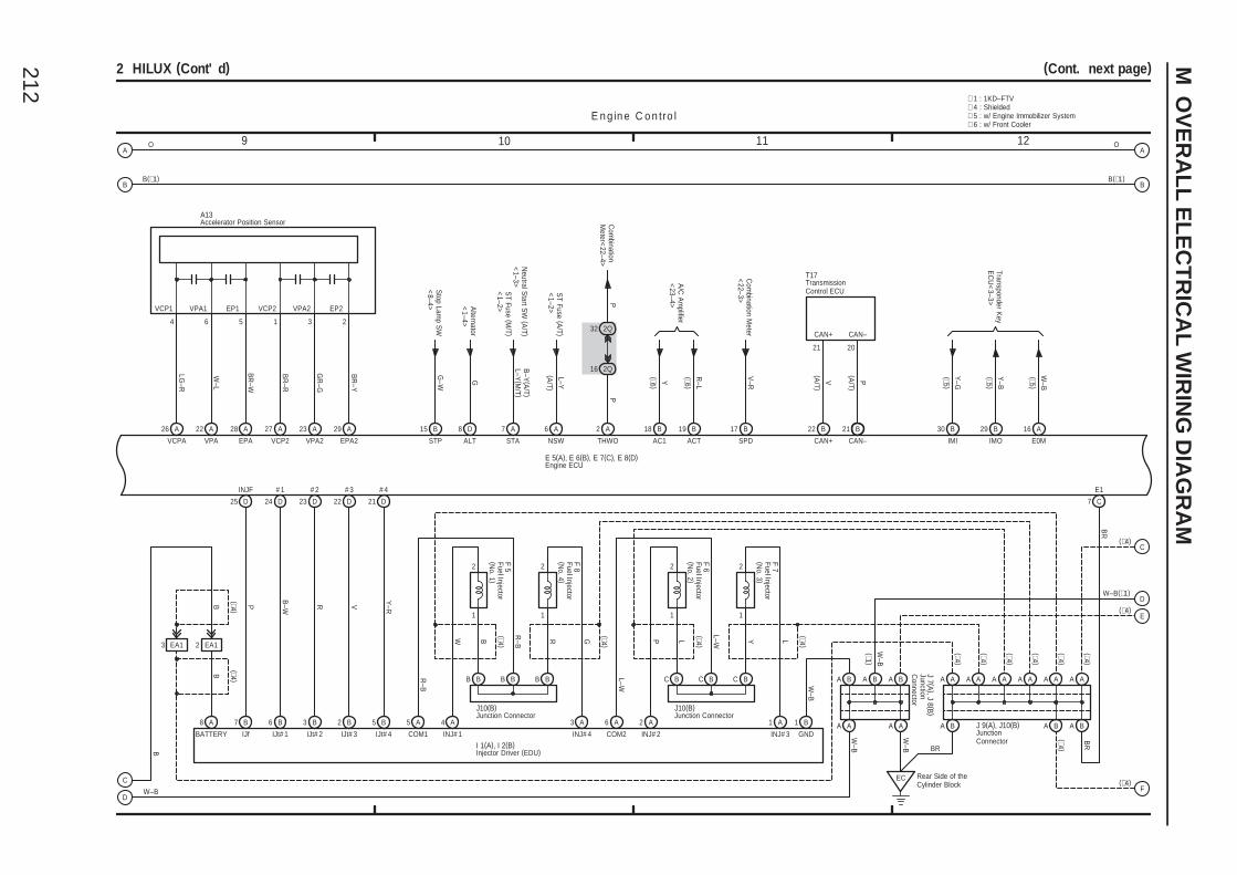
212
M O
VE
RA
LL
EL
EC
TR
ICA
L W
IRIN
G D
IAG
RA
M
9 10 11 12
2 HILUX (Cont' d) (Cont. next page)
E n g in e C o n tro l
26 A
VCPA
LG–R
4
VCP1 VPA1
Com
binationM
eter<22–4>
6
W–L
VPA
A22 28 A
EPA
BR
–W
D
P
THWO
A2
P
C
16
3
# 2
IJt# 2 IJt# 3
# 3
2
B
SPD
5
EP1
A13
ST Fuse (M
/T )<
1–2>
Neutral S
tart SW
(A/T )
<1–3>
B–Y
(A/T )
L–Y(M
/T )
7 A
STAALT
D8
GA
lternator<
1–4>
Stop Lam
p SW
<8–4>
G–W
15 B
STP
W–B
17
EP2
2Q
32 2Q
CAN+
21
E 5(A), E 6(B), E 7(C), E 8(D)
B B
OA
V
22
VCP2
1
BR
–R
VCP2
A27
2
BR
–Y
EPA2
A29
B
CAN–
23 A
D
VPA2
GR
–G
3
VPA2
22
V–R
Com
bination Meter
<22–3>
OA
B
D21
Y–R
5
# 4
IJt# 4
2
1
B
F 5 2
1
R
F 8
B B BB B B
4 A 3 A
2
1
L
F 6 2
1
Y
F 7
C B BC C B
2 A 1 A6 A
P LGW L–W
L–W
5 AR
–B
R–B
COM1 INJ# 1 INJ# 4 COM2 INJ# 2 INJ# 3
I 1(A), I 2(B)
J10(B) J10(B)
(∗4 )
(∗4 )
(∗4 )
(∗4 )
R
23 D
B6
# 1
IJt# 1
B–W
24 D
B7
INJF
IJf
P
25 D
B8
BATTERY
B
A
A A A A
W–B BR
W–B
BA
AAAA A A A A
A B A B
2 EA13 EA1
(∗4 )(∗4 )
B
(∗4 )
(∗4 )
(∗4 )
(∗4 )
(∗4 )
(∗4 )
(∗4 )
BR
BR
E1
C7
1 B
GND
A B
A A A A
EC Rear Side of theCylinder Block
W–B
J 9(A), J10(B)
J 7 (A ), J 8 (B )
C(∗4)
F(∗4)
B
A/C
Am
plifier<
23–4>Y R–L
18
AC1
19B B
ACT
B
30 B 29 B 16 A
IMI IMO E0M
Transponder Key
EC
U<
3–3>
Y–G
Y–B
W–B
∗ 4 : Shielded
BB(∗1)B(∗1)
A B A B
E
D(∗4)
W–B
(∗1 )
∗ 1 : 1KD–FTV
W–B(∗1)
Accelerator Position Sensor
Engine ECU
Fuel Injector(N
o. 1 )
Fuel Injector(N
o. 2 )
Fuel Injector(N
o. 3 )
Fuel Injector(N
o. 4 )
Injector Driver (EDU)
JunctionC
onnector
JunctionConnector
Junction Connector Junction Connector
ST Fuse (A
/T )<
1–2>L–Y
6 A
NSW
(A/T )
(∗5 )
(∗5 )
(∗5 )
∗ 5 : w/ Engine Immobilizer System
P(A
/T )
V(A
/T )
21 20
CAN+ CAN–
TransmissionControl ECU
T17
∗ 6 : w/ Front Cooler
(∗6 )
(∗6 )
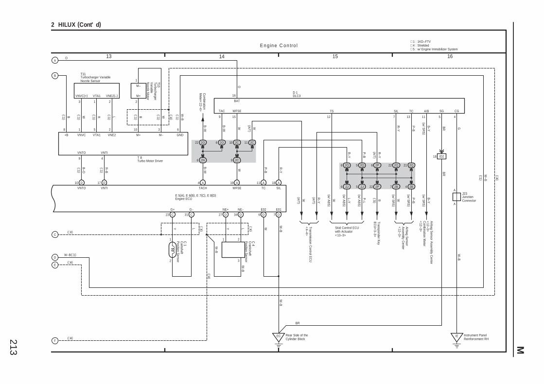
213 M
15 161413
2 HILUX (Cont' d)
E n g in e C o n tro l
LY
3
2
34 D
NE–
LY(∗4 )
(∗4 )
C 1
C 4
W
TS
(w/ A
BS
)
12 11B
–Y(w
/ SR
S)
A/BB
–Y
1
(w/ S
RS
)
W–B
G–
C31
1
2
G+
C23
(∗4 )
Skid Control ECUwith Actuator<13–3>
L–Y
P–L
W P–B
7 2B
2Q52Q6 21
B–W
Com
binationM
eter<22–4>
9
TAC
B–W
SIL
7
22 2Q
2O6
TC
13
R–Y
18 A
SIL
R–Y
11 A
TC
P–B
2Q
2J6 2B45 2J
E 5(A), E 6(B), E 7(C), E 8(D)
AO
BR
P–B
BAT
O
16
J23
W–B
Instrument PanelReinforcement RH
IE
G
6 2N
W
WFSE
A19
W
WFSE
15
D 1
BR
CG
4
4 A
5
(w/ A
BS
)
SG
(w/ A
BS
)
(w/ S
RS
)
TACH
B–W
R–Y
P–B
(w/ S
RS
)
22 2O
BR
27 D
NE+
W–B
A
A
18 ID2
C(∗4)
F(∗4)
W W–B
E01
D7D
E02
6
EC Rear Side of theCylinder Block
W–B
9 2C
2C10
2P6
2C11
(A/T )
W R–Y
(A/T )
Transmission C
ontrol EC
U<
4–4>
R–Y
(A/T )
W(A/T )
∗ 4 : Shielded
Airbag S
ensorA
ssembly C
enter<
12–3>
Airbag S
ensor Assem
bly Center
<12–3>
Com
bination Meter
<12–3>
VNTO VNTI
2P22
M–
B(∗5 )
M+
Transponder Key
EC
U<
3–3>
VNE2VTA1VNVC
10 D
VNTO VNTI
17 D
B
3 1 2 2
9 4
1 5 2 10
D
3
E
1
VNVC(+) VTA1 VNE2(–)
T10
T11
GND
6
R–B
(∗1 )
B–O
(∗1 )
(∗1 )WB(∗1 )
L(∗1 )
R(∗1 )
W(∗1 )
W–B
(∗1 )
W–B
(∗1 )
(∗4 )
W–B(∗1)
(∗4)
(∗4 )
T 8
∗ 1 : 1KD–FTV
∗ 5 : w/ Engine Immobilizer System
+B
8
B(∗1 )
Cam
shaftP
osition Sensor
Crankshaft
Position S
ensor
DLC3
Engine ECU JunctionConnector
M–
M+
Turbo Motor Driver
Turbocharger VariableNozzle Sensor Turbocharger
Variable
Nozzle M
otor
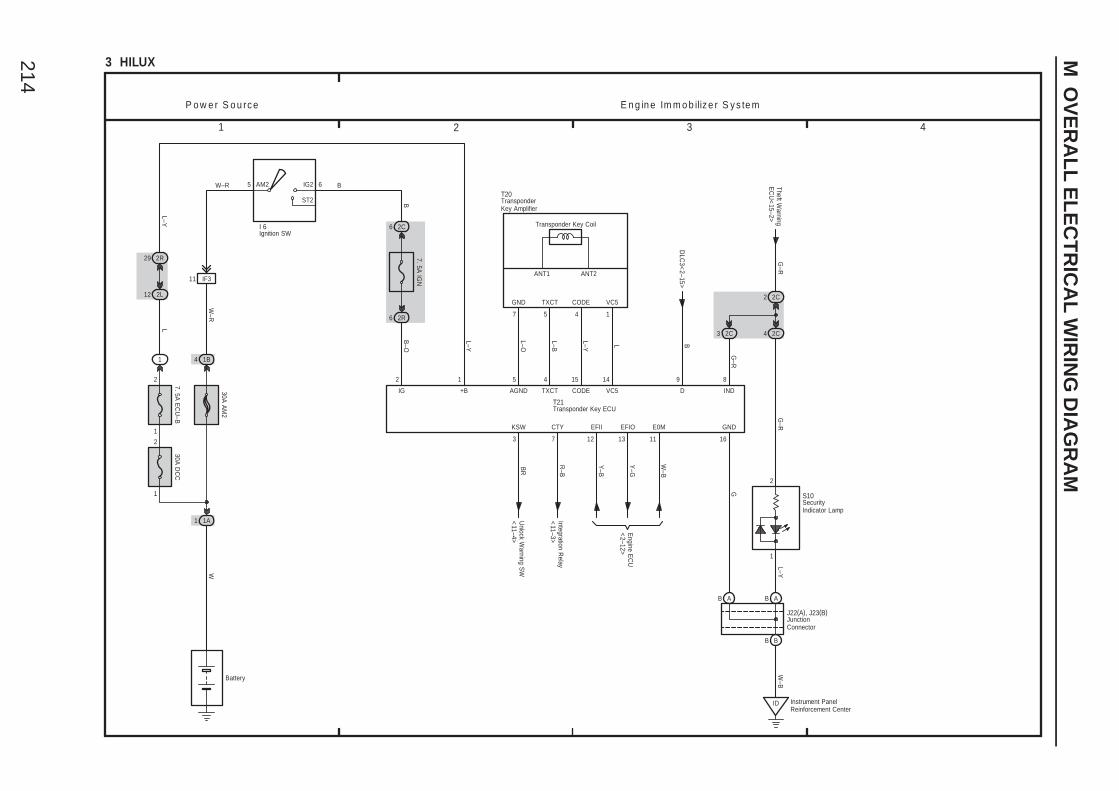
214
M O
VE
RA
LL
EL
EC
TR
ICA
L W
IRIN
G D
IAG
RA
M
1 2 3 4
3 HILUX
Battery
+B
L–Y
P o w e r S o u rc e E n g in e Im m o b iliz e r S y s te m
GND
B
B
1 1A
W
30A A
M2
2R
W–R
I 6
W–R
IG2
ST2
65 AM2
7. 5A IG
N
6 2C
6
16
12
IG
B–O
T21
5
AGND
L–O
4
L–B
TXCT CODE
L–Y
15 14
L
VC5
7
GND TXCT
5 4
CODE VC5
1
T20
D
B
9G
BR
KSW
3
Unlock W
arning SW
<11–4>
R–B
CTY
7 12
EFII
Y–B
Y–G
EFIO
13
Engine E
CU
<2–12>
Integration Relay
<11–3>
S10
ID Instrument PanelReinforcement Center
J22(A), J23(B)
DLC
3<2–15>
W–B
1B4
1
7. 5A E
CU
–B
2
2
30A D
CC
1
1
11 IF3
12 2L
2R29
L–YL
W–B
E0M
11
B AB A
B B
4 2C
2C2
2C3Theft W
arningE
CU
<15–2>
G–R
G–R
G–R
1
2
8
IND
Transponder Key Coil
ANT1 ANT2
Ignition SW
JunctionConnector
TransponderKey Amplifier
Transponder Key ECU
L–Y
SecurityIndicator Lamp

215
Memo
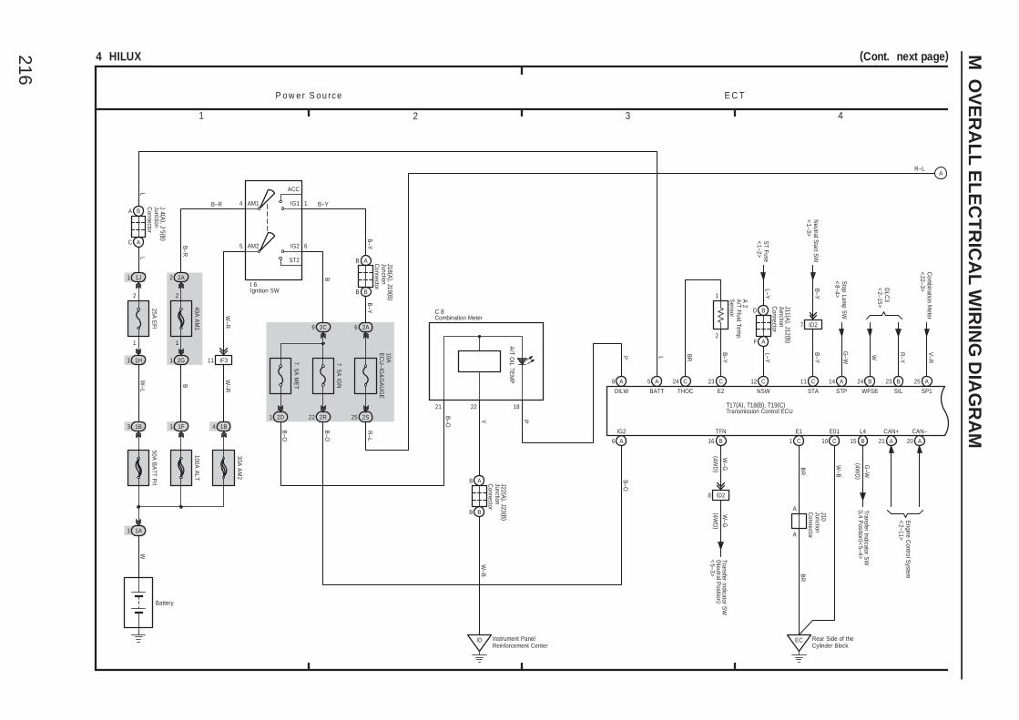
216
M O
VE
RA
LL
EL
EC
TR
ICA
L W
IRIN
G D
IAG
RA
M
1 2 3 4
4 HILUX (Cont. next page)
P o w e r S o u rc e
Battery
100A A
LT
1A1
WW
–L
1B3
50A B
ATT P
/I
30A A
M2
4 1B
W–R
W–R
5 IG2
ST2
6AM2
7. 5A IG
N
2C
B
6
I 6
E C T
CAN+
A21
EC Rear Side of theCylinder Block
2R22
B–O
R–L
L
1J1
J 4 (A ), J 5 (B )
A B
C A
L
T17(A), T18(B), T19(C)
L
BATT
5 A
CAN–
A20
W–B
E01
10 C
11 IF3
A
B–O
6 A
IG2
BB
AB
6
B–Y
10AE
CU
–IG&
GA
UG
E
2A
1
B–Y
AM1
B–R
2 2A
1
2
1 2G
IG1
ACC
4
25 2S
B
40A A
M1
1 1F
B–YB–R
R–L
J18 (A ), J19 (B )
BR
E1
1 C
A 2
1
2
23 C
E2
24 C
THOC
B–Y
BR
Engine C
ontrol System
<2–11>
11 C
STA
7 ID2
B–Y
B–Y
Neutral S
tart SW
<1–3>
12 C
NSW
L–YL–Y
ST Fuse
<1–2>
F
BD
A
J11 (A ), J12 (B )
23 B
SIL
R–Y
24 B
WFSE
W
A
SP1
25
V–R
Com
bination Meter
<22–3>D
LC3
<2–15>
25A E
FI
2
1
1H1
A
STP
14
G–W
Stop Lam
p SW
<8–4>
L4
B15
G–W
Transfer Indicator SW
(L4 Position )<
5–4>
B
TFN
8 ID2
16
W–G
W–G
A
A J10
Instrument PanelReinforcement Center
ID
C 8
B
AB
BJ22 (A ), J23 (B )
YW
–B
A8
OILW
7. 5A M
ET
2D1
A/T O
IL TEM
P
B–O
B–O P
P
21 22 18
Combination Meter
Ignition SW
JunctionC
onnector
JunctionC
onnector
JunctionC
onnector
JunctionC
onnector
JunctionC
onnector
Transmission Control ECU
BR
(4WD
)
(4WD
)(4W
D)
Transfer Indicator SW
(Neutral P
osition )<
5–3>
A/T Fluid Tem
p. S
ensor
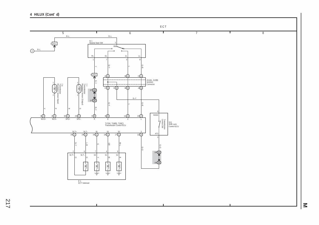
217 M
5 6 7 8
4 HILUX (Cont' d)
E C T
R–LA
T17(A), T18(B), T19(C)
3
A12
10 A
L
G–Y
2
A119 B
R
R–Y
2P27
27 2Q
L
G–R
G–RL
BC
AA
G–Y
BB
AB C A
A B
N 12 ID1
RB
LL2LDLRL
2
8371
18 2N
2O18
S11
G–O
J11(A), J12(B)
3 ID1
R–Y
Y
3
9
R–L
BC
G–O
2
C
4
SLT+
G–Y
20
6 7
19 C
SLT–
L–B
16 C
SL
G
C
W–L
S2
C17
8
18
GR
E 1
S1
BWYGO
R–L
8 B
D Transmission
Control S
W
AT3
NSSD
G–Y
1
2
29 C
SP2–
30 C
SP2+
GR
T 7
1
2
2 C
NCO–
3 C
NCO+
PV
T 6
SLT+ SLT– S3 S1 S2
ECT Solenoid
JunctionConnector
Neutral Start SW
Shift LockControl ECUTransmission Control ECU
Transmission
Revolution S
ensor (Output )
Transmission
Revolution S
ensor (Input )
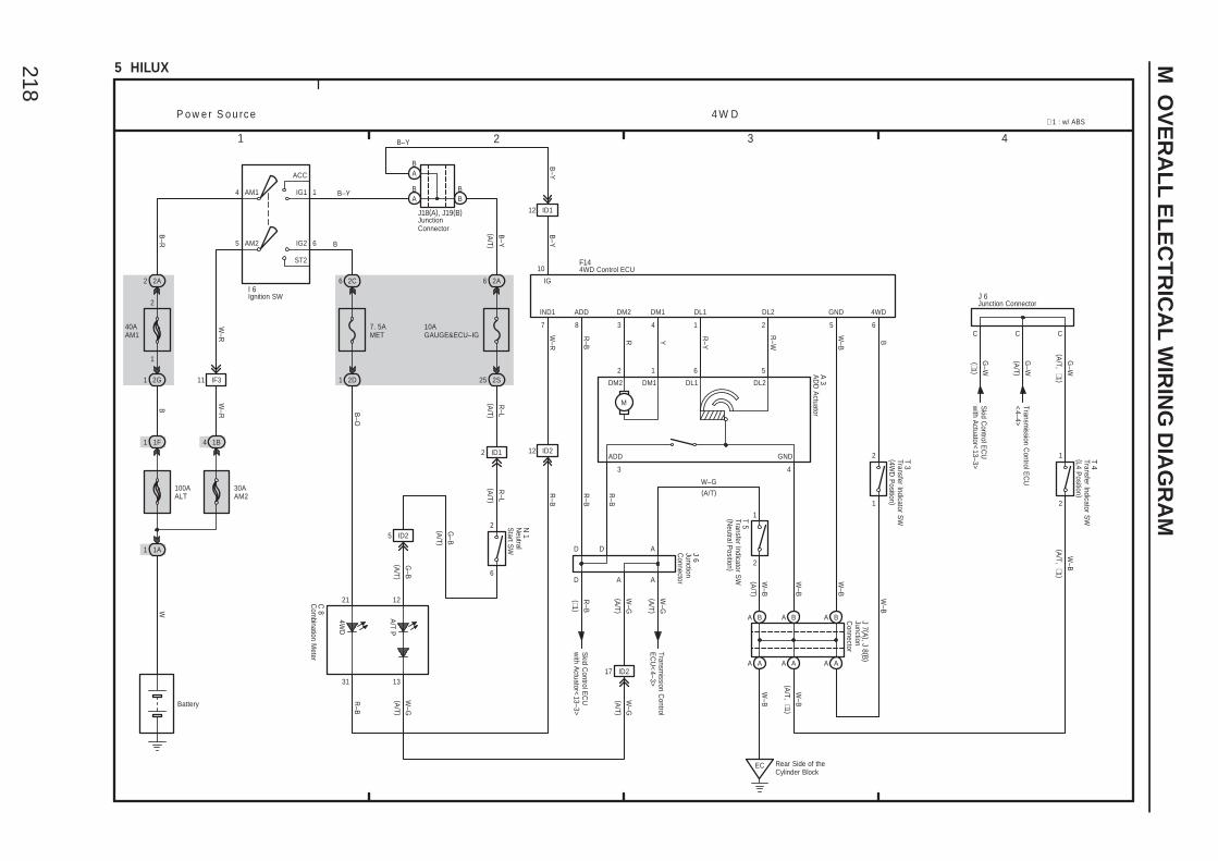
218
M O
VE
RA
LL
EL
EC
TR
ICA
L W
IRIN
G D
IAG
RA
M
1 2 3 4
5 HILUX
4
5
ACC
IG1
IG2
ST2
AM1 1
6AM2
2A2
40AAM1
2
1
2G1 11 IF3
1F1 1B4
100AALT
30AAM2
1A1
2A6
2S25
12 ID1
12 ID2
EC Rear Side of theCylinder Block
A B A B
A A A A
CCC
21
43
D
31
65243 187
10
21
D D
62 1 5
2 1
4WDGNDDL2DM1DM2 DL1ADDIND1
ADD GND
B–Y
B
B–Y
(∗1 )
G–W
W–B
B
W–B
R–WYR R–Y
R–B
W–R
B–O
R–B
R–B
B–Y
W–R
B
W–R
B–R
R–B
W–B
W–B
W–B
IG
DL2DM1DM2 DL1
4 W DP o w e r S o u rc e
I 6
F14
T 3
A 3
J 7 (A ), J 8 (B )
R–B
Skid C
ontrol EC
Uw
ith Actuator<
13–3>
A A
T 4
J 6
W–B
Skid C
ontrol EC
Uw
ith Actuator<
13–3>
Transmission C
ontrol EC
U<
4–4>
W
4WD
Ignition SWJunction Connector
JunctionC
onnector
Battery
M
A B
2
1T 5
R–B
Com
bination Meter
C 8
A A
A
BA
BB
JunctionConnector
J18(A), J19(B)
BA
2C6
7. 5AMET
2D1
10AGAUGE&ECU–IG
B–Y
B–Y
6
2
2 ID1
5 ID2JunctionC
onnector
J 6
(A/T )
(A/T )
R–L
(A/T )
R–L
(A/T )
G–B
(A/T )
G–B
(A/T )
W–G
(A/T )
W–G
(A/T )
W–G
12
13
Neutral
Start S
W
N 1
17 ID2
A/T P
(A/T )
W–G
(A/T)W–G
(A/T )
W–B
Transmission C
ontrolE
CU
<4–3>
W–B
(∗1 )
(A/T )
G–W
G–W
(A/T, ∗1 )
(A/T, ∗1 )
∗ 1 : w/ ABS
(A/T, ∗1 )
AD
D A
ctuator
Transfer Indicator SW
(4WD
Position )
4WD Control ECU
Transfer Indicator SW
(L4 Position )
Transfer Indicator SW
(Neutral P
osition )
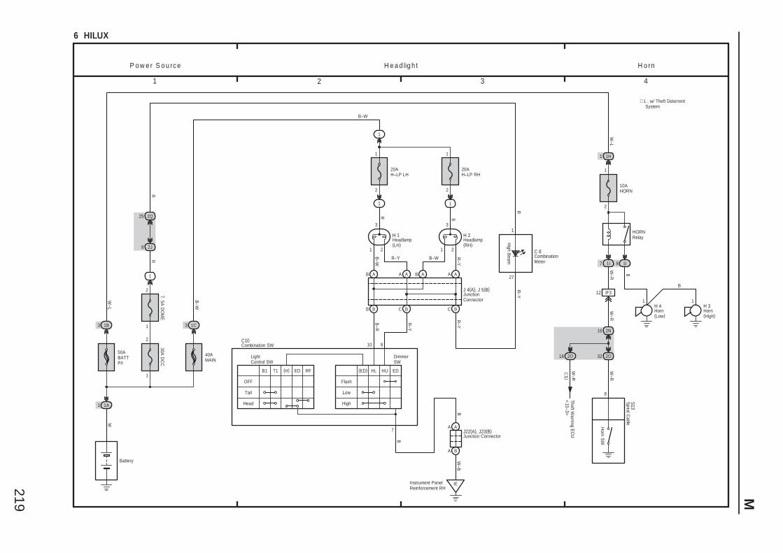
219 M
3 421
6 HILUX
B–W
B
B–R
R–Y
20AH–LP RH
IE
8
W–B
R–Y
P o w e r S o u rc e H e a d lig h t H o rn
2121
33
10AHORN
B
W–R
W–R
B
B11
2 2
1
1 1
1I1I
1H1
Instrument PanelReinforcement RH
1 1H 4 H 3
S13
Horn S
W
2N16
2O322O16
12 IF3
W–R
W–R
(∗1 )Theft W
arning EC
U<
15–3>
7 8
HORNRelay
W–L
1
2
50ABATTP/I
3 1B
Battery
W–L
1A1
W
40AMAIN
3 1C
B–W
A A
A B
J22(A), J23(B)
R
20AH–LP LH
B–W
B A A A
B B C B
H 1 H 2
DimmerSW
LightControl SW
10
EDHUHL(ED)
High
Low
Flash
ED(H)T1B1
Head
Tail
OFF
7
R–Y
B A A A
C B
B–W
C10
J 4(A), J 5(B)
High B
eam27
1
C 8
R–Y
B
R
8 2J
R
1
1
2
30A D
CC
7. 5A D
OM
E
2
1
2Q25
R
∗ 1 : w/ Theft Deterrent System
RF
CombinationMeter
Headlamp(LH)
Headlamp(RH)
Horn(High)
Horn(Low)
Combination SW
JunctionConnector
Junction Connector
Spiral C
able
R–Y
9
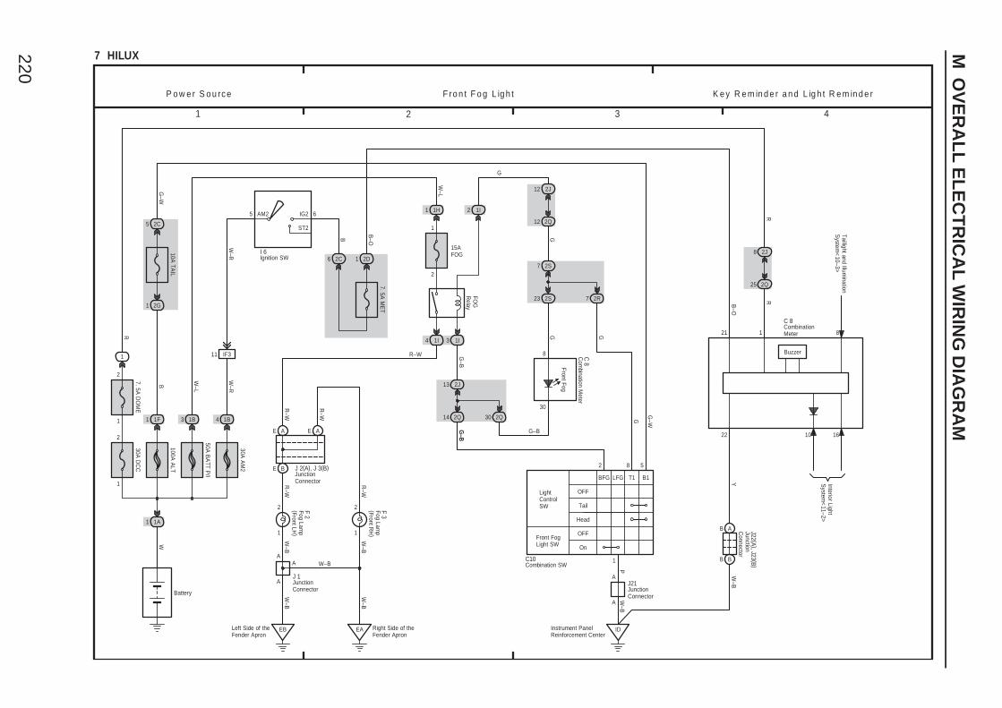
220
M O
VE
RA
LL
EL
EC
TR
ICA
L W
IRIN
G D
IAG
RA
M
1 2 3 4
7 HILUX
IDInstrument PanelReinforcement Center
1I 1I
FOG
Relay
P o w e r S o u rc e F ro n t F o g L ig h t
Front Fog
C 8
P
2
1
2
1
R–W
R–W
F 2
F 3
AE
E B
R–W
23 2S
G
7 2S
G–B
A
AJ21
E A
R–W
R–W
J 2(A), J 3(B)
14 2Q
G–B
G–B
13 2J
2Q30
30
8
34
50A B
ATT P
/I
10A TA
IL
1 2G
3 1B
B
Battery
1 1F
100A A
LT
1A1
WG
–W
2C5
15AFOG
W–L
1H1
2
1
W–L
1I2
12 2Q
2J12
G
G
W–B
W–B
Right Side of the Fender Apron
EALeft Side of theFender Apron
EB
A
J 1A
W–B
W–B
W–BA
2R7
G 21
B–O
1 2D6
B
2C
7. 5A M
ET
AM2 6
ST2
22
IG25
30A A
M2
4 1B
W–R
I 6
B–O
W–B
BB
AB
Y
W–R
J22 (A ), J23 (B )
C 8
8
10 16
Taillight and Illumination
System
<10–3>
Interior LightS
ystem<
11–2>
Buzzer
K e y R e m in d e r a n d L ig h t R e m in d e r
25 2Q
2J8
1
2
7. 5A D
OM
E30A
DC
C
2
1
1
R 1
RR
11 IF3 Com
bination Meter
CombinationMeter
Fog Lamp
(Front LH)
Fog Lamp
(Front RH
)
Ignition SW
JunctionConnector
JunctionConnector
JunctionConnector
JunctionC
onnector
On
LFG
OFFFront FogLight SW
BFG
Tail
T1
OFFLightControlSW
B1
Head
G–B
G
G–W
2 8 5
1
W–B
Combination SWC10
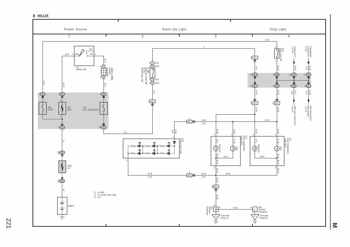
221 M
3 421
8 HILUX
2 A
2 B
1 B
1 A
Back–U
p
Stop
Back–U
p
Stop
P o w e r S o u rc e B a c k – U p L ig h t S to p L ig h t
(M/T)
(M/T)
(A/T)
(A/T)
W–B
G–W
∗ 3 : A/T
G–W
(∗2 )
G–W
G–W
2S
R–L
2A6
W–B
10AECU–IG&GAUGE
R 5 R
4
3 3
455 4
R–W
R–W
B 1 (B )
N 1 (A )
G–W
2I10
R–W
2 ID1
25
2K5
BB
AB
B–Y
1
B–Y
AM1
B–R
2 2A
1
2
1 2G
IG1
ACC
4
B
40AAM1
Battery
1 1F
B–R
100AALT
1A1
W
I 6 J18 (A ), J19 (B )
10ASTOP
G–B
2 2F
R–L
2Q27
R–Y
2M5
2S5
G–Y
(∗3 )
(∗1 )G
–W
5 2L
Engine E
CU
<2–10>
G–W
21 2S
Transmission
Control E
CU
<4–4>
G–W
(∗3 )
2R21
Shift Lock C
ontrol EC
U<
19–4>
Skid C
ontrol EC
Uw
ith Actuator
<13–3>
∗ 1 : w/ ABS
W–B
∗ 2 : w/ Center Stop Lamp
6 BA15 BA1
G–W
R–W
IG
AJ28
Cowl SidePanel RH
IF
A
8 BA1
W–B
G–W(∗2)
W–BA
W–B(∗2)
C13
1
2
3 ID1
BD11
BD12
(∗2)W–B
Y
Neutral S
tart SW
Center S
top Lamp
Ignition SW
JunctionC
onnector
JunctionConnector
Back–U
p Lamp S
W
Rear C
ombination
Lamp (LH
)
Rear C
ombination
Lamp (R
H)
1
2 S14S
top Lamp S
W
G–W
G–B
G–W
R–L
G–W
R–L
W–B
W–B
W–B
W–B
W–BW–B
W–B
Cowl SidePanel LH
JunctionC
onnector
J15
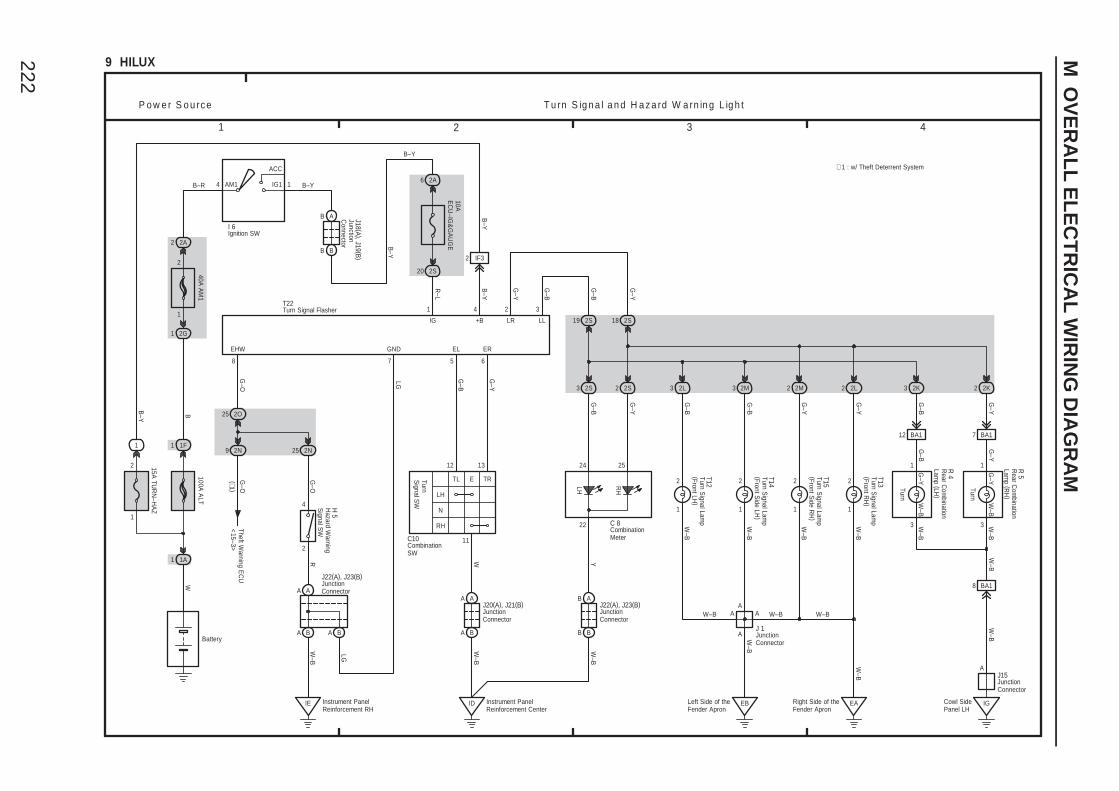
222
M O
VE
RA
LL
EL
EC
TR
ICA
L W
IRIN
G D
IAG
RA
M
3 421
9 HILUX
5
41
6
LH
RH
TL E TR
11
G–B
1
2 2
1
EA
G–Y
G–B
R–L
B–Y
G–Y
G–Y
G–B
G–Y
G–B
P o w e r S o u rc e T u rn S ig n a l a n d H a z a rd W a rn in g L ig h t
W–B
W–B
W
W–B
W–B
W–B
A
EB
Y
AA
W–B
Left Side of theFender Apron
BB
AB
6
B–Y
10AE
CU
–IG&
GA
UG
E
2A1AM1
2 2A
1
2
1 2G
IG1
ACC
4
20 2S
B
40A A
M1
Battery
1 1F
B–YB–R
100A A
LT
1A1
W
15A TU
RN
–HA
Z
2
1
I 6
J18 (A ), J19 (B )
1
3
1
3
2K3 2K2
R 4
R 5
LH RH
22
24 25
2L22S22S3 2L3
T13
T12
J 1
C 8
W–B
W–B
TurnS
ignal SW
12 13
A A
A B
ID Instrument PanelReinforcement Center
W–B
J20(A), J21(B)
BB
ABJ22(A), J23(B)
W–B
C10
T22
EL ER
IG +B
Turn
Turn
LG
1
B–Y
2 IF3
B–Y
A A
A B A B
IE Instrument PanelReinforcement RH
2O25
2N9 2N25
2
4
EHW
G–O
8
G–O
(∗1 )
G–O
R
H 5
Theft Warning E
CU
<15–3>
W–B
LG
7
GND
J22(A), J23(B)
B–Y
Right Side of theFender Apron
LR
2 3
G–B
LL 2S19 2S18
G–Y
G–B
G–Y
2M
1
2
G–B
W–B
T14
2M
T15
1
W–B
G–Y
2
A
3 2
W–B
G–Y
G–B
12 BA1 7 BA1
8 BA1
J15
Cowl SidePanel LH
IG
A
W–B
W–B
∗ 1 : w/ Theft Deterrent System
CombinationMeter
Hazard W
arningS
ignal SW
CombinationSW
Ignition SW
JunctionConnector
JunctionConnector
JunctionC
onnector
JunctionConnector
JunctionConnector
JunctionConnector
Rear C
ombination
Lamp (LH
)
Rear C
ombination
Lamp (R
H)
Turn Signal Lam
p(Front LH
)
Turn Signal Lam
p(Front R
H)
Turn Signal Flasher
G–Y
W–B
G–Y
W–BN
Turn Signal Lam
p(Front S
ide LH)
Turn Signal Lam
p(Front S
ide RH
)

223
Memo
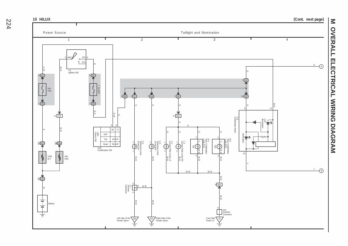
224
M O
VE
RA
LL
EL
EC
TR
ICA
L W
IRIN
G D
IAG
RA
M
3 421
10 HILUX
1
2 2
1 2
1
EB
W–B
G G G
G GGW
–B
T a illig h t a n d Illu m in a tio nP o w e r S o u rc e
W–B
G
W–B
Y
BA111
W–B
W–B
W–B
C 8
7 2R
8
22
5 2C
G–W
W
1 1A
100AALT
1F1
Battery
B
2G1
10ATAIL
5
Tail
T1
OFF
LightC
ontrol SW
B1
C10
8
G
Head
G–W
2
3
2
3
R 4
R 5
Tail
Tail
L 2
2K7 2S232L7 2M7
IlluminationC
3
C 2
A
A
EA Right Side of theFender Apron
A W–B
J 1Left Side of theFender Apron
B–O
21
6
7. 5A M
ET
2C
AM2 6
ST2
IG25
W–R
30AAM2
4 1B
W–R
I 6
B–O
2D1
2S7
G
A
BY
G
(Cont. next page)
B
11 IF3
2
1
GW
–B
L 1
G
G
W–B W–B
8 BA1
J15
Cowl SidePanel LH
IG
A
W–B
W–B
Clearance Lam
p(Front LH
)
Clearance Lam
p(Front R
H)
Com
bination Meter
Combination SW
Ignition SW
JunctionC
onnector
JunctionConnector
Rear C
ombination
Lamp (LH
)
Rear C
ombination
Lamp (R
H)
G GW
–B
W–B
LCD
Illumination
License Plate Lam
p RH
License Plate Lam
p LH
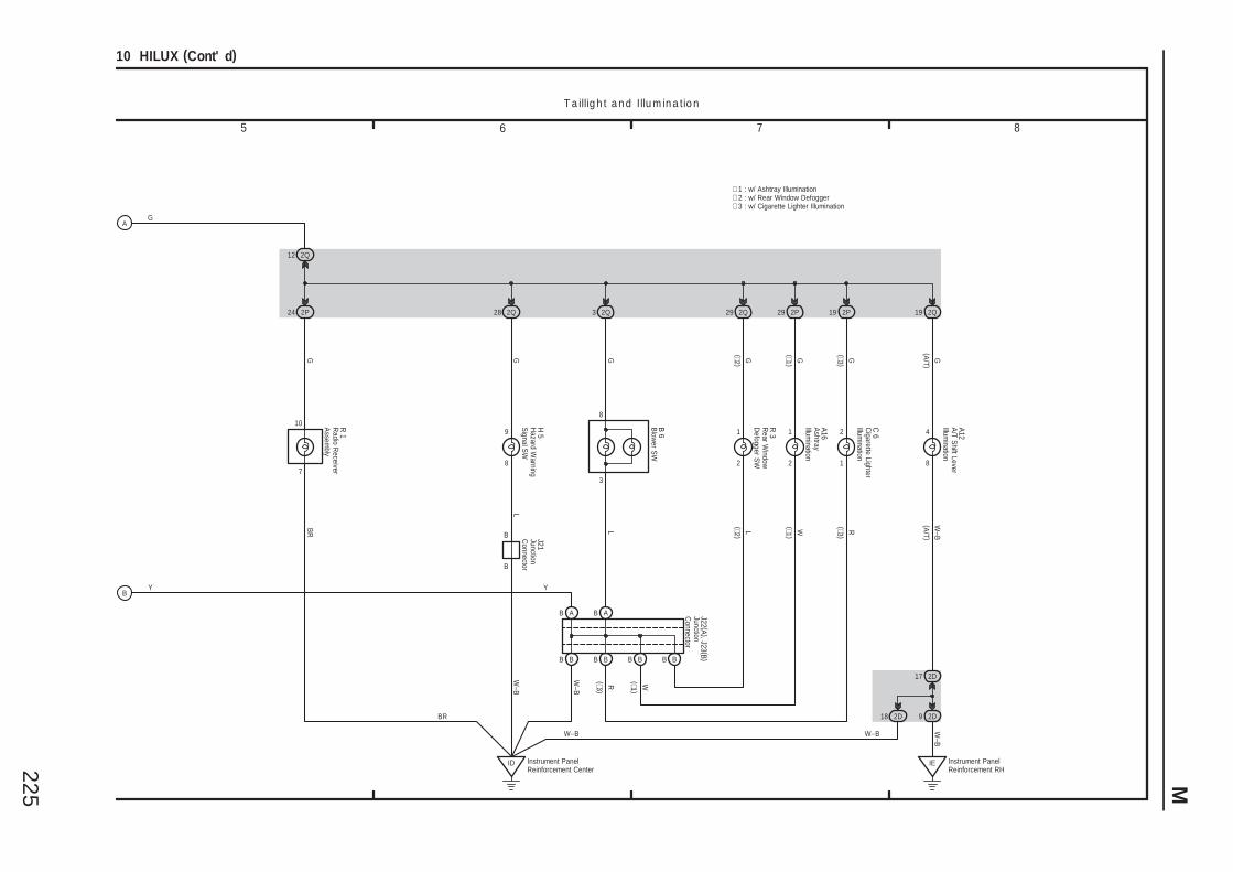
225 M
5 6 7 8
10 HILUX (Cont' d)
T a illig h t a n d Illu m in a tio n
∗ 1 : w/ Ashtray Illumination∗ 2 : w/ Rear Window Defogger∗ 3 : w/ Cigarette Lighter Illumination
R(∗3 )
(∗1 )W
BR
Y
W–B
G
YB
A
C 6
(∗3 )(∗3 )
1
2
GR
2P19
A16
(∗1 )(∗1 )
2
1G
W
2P
BB
H 5
GL
8
9
292Q28
R 3
(∗2 )(∗2 )
2
1
GL
2Q29
12 2Q
BB
AB J22 (A ), J23 (B )
J21
2D18
17 2D
2D9
Instrument PanelReinforcement RH
IE
W–B
B
BBBB
AB
R 1
B 6
A12
W–B
3
8
(A/T )
(A/T )
G
8
4
GW
–B
GB
R L
7
10
W–B
2P24
ID Instrument PanelReinforcement Center
W–B
2Q3 2Q19
B
Ashtray
Illumination
Cigarette Lighter
Illumination
Hazard W
arningS
ignal SW
JunctionC
onnector
JunctionC
onnector
Radio R
eceiverA
ssembly
Rear W
indowD
efogger SW
Blow
er SW
A/T S
hift LeverIllum
ination
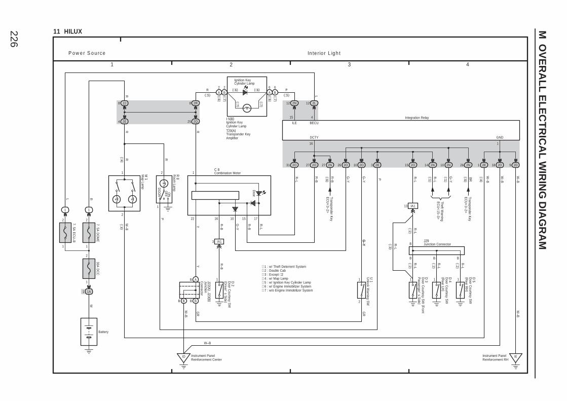
226
M O
VE
RA
LL
EL
EC
TR
ICA
L W
IRIN
G D
IAG
RA
M
3 421
11 HILUX
1
2
DO
OR
OFF
ON
11 11
P o w e r S o u rc e In te r io r L ig h t
R–L
R–L
R–L
∗ 2 : Double Cab
B B B
B
13 IA1
1
2
RW
–B
R 8
M 1
P
R–L
J29
D 5
D 4
D 3D
2
3 IA1
R–B
R–B
R–L
2O15
1
2
7. 5A D
OM
E
Battery
1A1
W
30A D
CC
2
1
1
R
2D92D18
IEInstrument PanelReinforcement RH
W–B
2J8
2Q252E4
R
R–B
2O27
16
R–L
31 2O
Door
G–Y
26 2O
10 15 1716
R–L
R–B
G–Y
DCTY
22
B A
B B
Y
J22 (A ), J23 (B )
1C 8
Integration Relay
R
GND
1
2E1
1
2
7. 5A E
CU
–B
1
L
4
BECU
L
2L12
P
3 2E
∗ 1 : w/ Theft Deterrent System
ID Instrument PanelReinforcement Center
Y
G–Y
2O10
2
1
W–B
W–B
14 2N
R–L
G–Y
2N10
(∗1 )
(∗1 )
B B
W–B
U 1
G–Y
G–Y
GR
W–B
R
∗ 3 : Except ∗2
Theft Warning
EC
U<
15–3>
(∗6 )
26 2N
BR
Transponder Key
EC
U<
3–2>
(∗2 )
(∗2 )(∗2 )
(∗2 )
R–L
(∗3 )
15
2N122R8
T20(A)
R
(∗6 )
27
R–B
2N
Transponder Key
EC
U<
3–2>
Combination Meter
Door C
ourtesy SW
(Driver'
s Side )
Door C
ourtesy SW
(FrontP
assenger's S
ide )
Door C
ourtesy SW
(Rear LH
)
Door C
ourtesy SW
(Rear R
H)
JunctionC
onnector
Junction Connector
Map Lam
p
Transponder KeyAmplifier
Unlock W
arning SW
GR
∗ 4 : w/ Map Lamp
(∗4 )(∗4 )
W–B
(∗4 )
Ignition KeyCylinder Lamp
(∗5)P
(∗5)R
ILEI 5(B)
∗ 6 : w/ Engine Immobilizer System∗ 5 : w/ Ignition Key Cylinder Lamp
∗ 7 : w/o Engine Immobilizer System
2
B
2
A
6
A
6
B
(∗6 )(∗7 )
(∗6 )(∗7 )(∗7 )
(∗7 )
(∗6)(∗6)
Room
Lamp
Ignition KeyCylinder Lamp
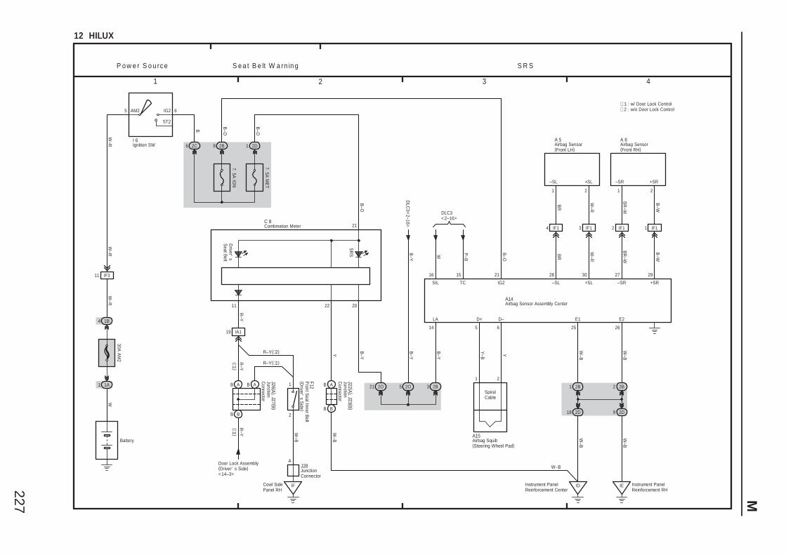
227 M
3 421
12 HILUX
B–O
W P–B
TCSIL IG2 +SL–SL
W–R
BR
21
+SR–SR
B–W
BR
–W
21
E1 E2
ID IE
W–B
W–B
S R SP o w e r S o u rc e
+SR+SL –SR–SL
D+ D–
Y–B Y
1 2
Instrument PanelReinforcement Center
Instrument PanelReinforcement RH
SR
S
B–O
I 6
W–R
1B4
30A A
M2
W
1 1A
Battery
W–R
5 IG2
ST2
6AM2
7. 5A M
ET
2C
B
6 2D1
B–O
7. 5A IG
N
2B8
B–O
22
21
Y
B A
B B
W–B
1516 21 27 2928 30
5 6 25 26
W–B
W–B
18 2D
2B1
9 2D
2B2
A15
A1420
B–Y
2B32O21 2O5
LA
B–Y
14
B–Y
B–Y
DLC3<2–16>
2 IF1
W–R
BR
B–W
BR
–W
IF11IF14 IF13
A 6A 5
∗ 2 : w/o Door Lock Control
W–R
J22 (A ), J23 (B )
J26 (A ), J27 (B )
R–Y
B A B A
B B
R–Y
F12
19 IA1
2
1
IFW
–B
AJ28
Driver'
sS
eat Belt
Cowl SidePanel RH
11
R–Y
C 8
Door Lock Assembly(Driver' s Side)<14–3>
W–B
DLC
3<2–16>
S e a t B e lt W a rn in g
∗ 1 : w/ Door Lock Control
11 IF3
(∗1 )(∗1 )
R–Y(∗2)
R–Y(∗1)
Airbag Sensor(Front LH)
Airbag Sensor(Front RH)
Airbag Sensor Assembly Center
Airbag Squib(Steering Wheel Pad)
Combination Meter
Front Seat Inner B
elt(D
river's S
ide )
Ignition SW
JunctionC
onnector
JunctionC
onnector
JunctionConnector
SpiralCable
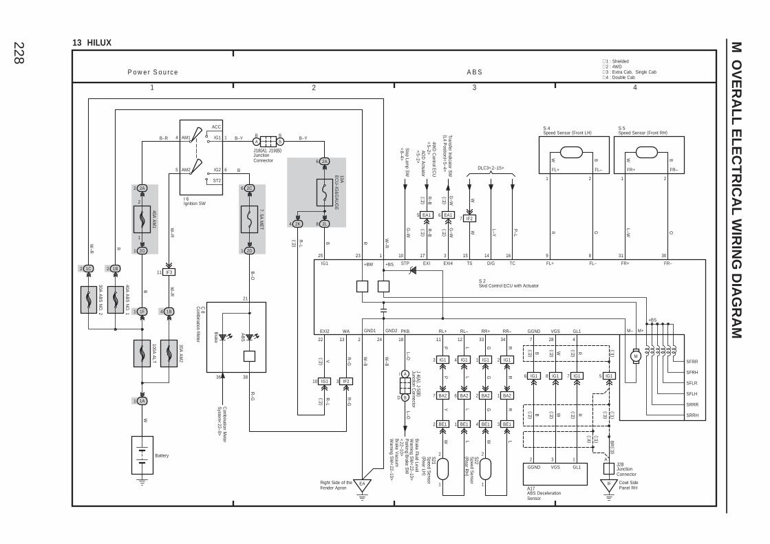
228
M O
VE
RA
LL
EL
EC
TR
ICA
L W
IRIN
G D
IAG
RA
M
1 2 3 4
13 HILUX
P o w e r S o u rc e A B S
6
6
2C
7. 5A M
ET
10AE
CU
–IG&
GA
UG
E
AM2 6
2A
1AM1
ST2
2 2A
1
2
1 2G
IG2
IG1
ACC
5
4
W–R
8 2L
B
40A A
M1
Battery
1 1F
B–YB–R
B
100A A
LT
1A1
W
30A A
M2
4 1B
W–R
I 6
2D1
B–O
∗ 1 : Shielded
B
40A A
BS
NO
. 1
30A A
BS
NO
. 2
2 1C
W–R
2 1B
R
23
R
1
W–R
EARight Side of theFender Apron
2
W–B
24
W–B
BA
BB
J18(A), J19(B)
B–Y
25
IG1
S 2
AB
S
Brake
R–G
22
EXI2
VR
–L
10 IG1
Com
bination Meter
System
<22–9>
11 IF3
13
WA
R–G
R–G
3 IF2
2K4
R–L
M–
SRRR
SRRH
SFLH
SFLR
SFRH
SFRRM
+BS
M+
+BM +BS
GND1 GND2
7
GGND
B
28
VGS
W
6 IG1
B
8 IG1
W
4
GL1
R (∗1 )
7 IG1
R
5 IG1
(∗1 )
2 3 1
A17
GL1VGSGGND
IF
A
BR
(∗3 )
J28
18
PKB
L–O
I A
D B
L–O
J 4 (A ), J 5 (B )
Parking B
rake SW
<22–10>
Brake V
acuumW
arning SW
<22–10>
Brake Fluid Level
Warning S
W<
22–10>G
–W
STP
10
Stop Lam
p SW
<8–4>
W
TS
15
W
L–Y
D/G
14P
–L
TC
16
7 IF2
DLC3<2–15>
9
FL+
R
8
FL–
G
S 4
31
FR+
L–W
30
FR–
O
S 5
R–B
EXI
17
R–B
4WD
Control E
CU
<5–2>
5 EA1
G–W
EXI4
3
G–W
Transfer Indicator SW
(L4 Position )<
5–4>
6 EA1
2121
BWBW
FL+ FL– FR+ FR–
7 BA2
W
6 BA2
L
2 BA2
W
1 BA2
L
11
RL+P
12
RL–
L
3 IG1
P
4 IG1
L
33
RR+
G
34
RR–
R
1 IG1
G
2 IG1
R
2 BE1 1 BE1 4 BE1 3 BE1
Y L G R
S22
S21
Ignition SW
Junction Connector
JunctionConnector
JunctionConnector
Skid Control ECU with Actuator
Speed Sensor (Front LH) Speed Sensor (Front RH)
Speed S
ensor(R
ear LH)
Speed S
ensor(R
ear RH
)
1 1
22
Com
bination Meter
C 8
(∗2 )(∗2 )
(∗2 )(∗2 )
(∗2 )
(∗2 )(∗2 )
(∗2 )
(∗2 )
(∗2 )(∗2 )
(∗2 )
(∗2 )
∗ 2 : 4WD
ABS DecelerationSensor
21
3836
Cowl SidePanel RH
∗ 3 : Extra Cab, Single Cab∗ 4 : Double Cab
(∗3 )
(∗1 )(∗4 )
AD
D A
ctuator<
5–2>
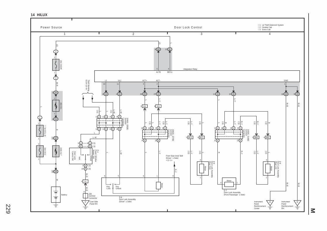
229 M
3 421
14 HILUX
IF
4 BC15 BC1 5 BB1 4 BB1
RLL–Y
R R–Y
L–Y L
R–Y
R
P o w e r S o u rc e D o o r L o c k C o n tro l
Unlock
W–B
Cowl SidePanel RH
G A G A
G B G B
F A F A
H B H B
A
4 II1
W–B
J28
P 4
J24 (A ), J25 (B ) D A D A
F B
F A F A
D B
L
6
L–W
5
L
4
L–Y
1
R–Y
8
D 6
J26 (A ), J27 (B )
IH18
L–Y
L–Y
IH13
L L
E A
D B
D A E A
E B
L
A
R–Y
L–Y
D
2K11 2K10
1
2
7. 5A E
CU
–B
2
1
2H2
W–R
1 2G
B
40A IG
1
Battery
1 1F
100A A
LT
1A1
W
30A D
CC
2
1
1
L
LG
2H4
2D92D18
IEInstrumentPanelReinforcementRH
IDInstrumentPanelReinforcementCenter
W–B
Front Seat Inner Belt(Driver' s Side)<12–1>
2D42A4
L(∗1 )
L–W(∗1 )
L
L–W
Theft Warning
EC
U<
15–4>
14 11
L1 UL1
W–B
W–B
2R28
3
ACT+
2R27
2
ACT–
L L–Y
L–YL
1
GND
Integration Relay
L–Y L
LG
3
2
1
3
25A D
OO
R
5
ALTB
12 2L
L
4
BECU
∗ 3 : Extra Cab∗ 2 : Double Cab∗ 1 : w/ Theft Deterrent System
J13 (A ), J14 (B )
L
L–W
4 B (∗3)
8 A (∗2)
3 B
5 A
3 A (∗2)
10 B (∗3)
Motor
4
Motor
D 8
1
Motor
4 D 9
1
Motor
D 7
4 1
Door Lock Assembly(Driver' s Side)
Door Lock Assembly(Front Passenger' s Side)
Door Lock A
ssembly
(Rear LH
)
Door Lock A
ssembly
(Rear R
H)
JunctionC
onnector
JunctionC
onnector
JunctionC
onnector
JunctionConnector
Pow
er Window
Master S
W
KeyLock
KeyUnlock
lock
Door Lock
Control S
W
W–B
(∗2 )
(∗2 )(∗2 )
(∗2 )
(∗2 )
(∗2 )
(∗2 )
(∗2 )(∗2 )
(∗2 )
(∗2 )
(∗2 )
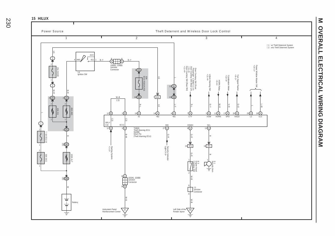
230
M O
VE
RA
LL
EL
EC
TR
ICA
L W
IRIN
G D
IAG
RA
M
3 421
15 HILUX
P o w e r S o u rc e T h e ft D e te rre n t a n d W ire le s s D o o r L o c k C o n tro l
1
2
7. 5A E
CU
–B
2
6
1
2H2
W–R
10AE
CU
–IG&
GA
UG
E
2A
1AM1
B–R
2 2A
1
2
1 2G
IG1
ACC
4
B
40A A
M1
40A IG
1
Battery
1 1F
B–Y
100A A
LT
1A1
W
30A D
CC
2
1
1
L
I 6
LG
3
2
1
3
25A D
OO
R
BA
BB
J18(A), J19(B)
B–Y
IG
2S16
18 A
R–L
LG
A14
+B2
L–Y
A4
+B1
7 IH1 13 2S
2L12
L
R–L
A7
CTY
Unlock W
arning SW
<11–4>
KSW
5 A
G–Y
W–R
A11
HORNH
OR
N R
elay<
6–4>
Com
bination Meter
<22–3>
SPD
17 A
V–R
G–O
A28
HAZD
Turn Signal Flasher
<9–1>
B12 B1
(∗2)W–B
E(∗1)SRLY(∗1)
12 A 1 A
B–W
Starting S
ystem<
1–2>
B A
B B
IDInstrument PanelReinforcement Center
W–B
T16(A)
S12(B)
J22(A), J23(B)
DSWH
9 A
G–R
15 IF3G
–R
SH–
13 A
B
13 IF3
B
2
1
A
A
EBLeft Side of theFender Apron
W–B
W–B
1E 3
S 1
J 1
L–W
A26
UL3L2
25 A
L
Pow
er Window
Master S
W<
14–1>
∗ 2 : w/o Theft Deterrent System∗ 1 : w/ Theft Deterrent System
(∗2 )
(∗2 )
Door C
ourtesy SW
(Rear LH
)<
11–4>D
oor Courtesy S
W (R
ear RH
)<
11–4>
Door C
ourtesy SW
(FrontP
assenger's S
ide )<11–4>
Security Indicator
Light<3–3>
A27
IND
G–R
Engine H
oodC
ourtesy SW
Ignition SW
JunctionConnector
JunctionConnector
JunctionConnector
Short Pin(Theft Warning ECU)
LG
Theft Warning ECU
Security H
orn
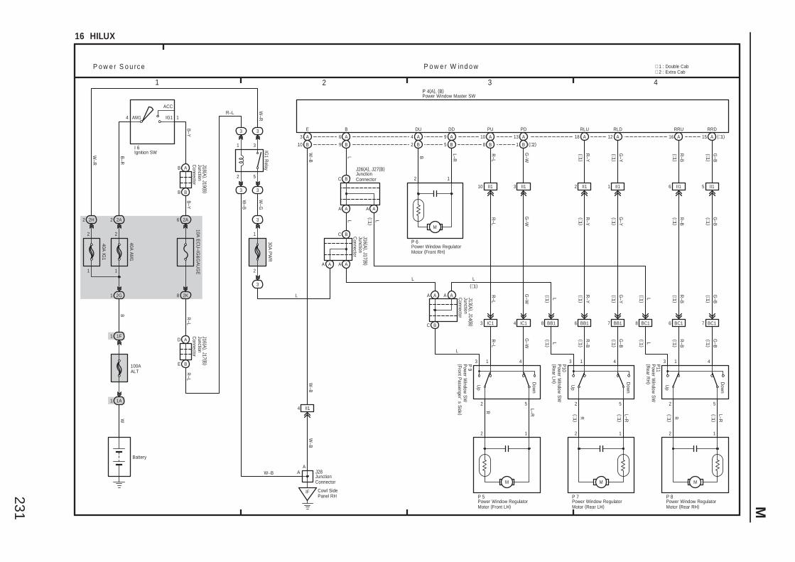
231 M
3 421
16 HILUX
IF
5 II16 II11 II12 II13 II110 II1
8 BB1 6 BB1 7 BB1 7 BC16 BC1BC18IC143 IC1
Dow
n
Up
2 5
3 1 4
R
Dow
n
Up
2 5
3 1 4
R
M
Dow
n
Up
2 5
3 1 4
R
G–B
R–Y
R–B
G–Y
G–W
R–L
R–L
W–B
L–RB
G–Y
G–W L
R–B
G–B
R–B
G–B
G–B
R–BL
R–Y
G–W
R–L
L–R
L
L–R
L–R
L
P o w e r S o u rc e P o w e r W in d o w
L
Cowl SidePanel RH
P 4(A), (B)
A
4 II1
J28
W–B
W–B
2 1
P 6
P11
P10
P 9
A A A A
C B
L
C B
A A A A
C B
A AA A
J16 (A ), J17 (B )
L
BB
AB
2
3
5
6
2
1
2H2
W–R
B–Y
10A E
CU
–IG&
GA
UG
E
2A
1
B–Y
AM1
B–R
BE
AD
2 2A
1
2
1 2G
IG1
ACC
4
R–L
8 2K
B
40A A
M1
40A IG
1
Battery
1 1F
IG1 R
elay
R–L
W–R
1
100AALT
1A1
W
3
3 3
3
W–B
30A P
WR
3
2
1
3
W–G
I 6
J18 (A ), J19 (B )J16 (A ), J17 (B )
AW–B
RRDRRURLDRLUPDPUDDDUE
R–L
G–Y
G–W
R–Y
R–B
G–B
L
B
J26(A), J27(B)
∗ 1 : Double Cab∗ 2 : Extra Cab
J13 (A ), J14 (B )
15 A (∗1)16 A12 A18 A13 A
1 B (∗2)
10 A
8 B
9 A
5 B
4 A
2 B
3 A
10 B
6 A
9 B
M
12
P 5
R–L
L
L
P 8
2 1
M
P 7
2 1
M
Ignition SW
JunctionC
onnector
JunctionC
onnector
JunctionC
onnectorJunctionC
onnector
JunctionConnector
JunctionConnector
Power Window Master SW
Power Window RegulatorMotor (Front LH)
Power Window RegulatorMotor (Front RH)
Power Window RegulatorMotor (Rear LH)
Power Window RegulatorMotor (Rear RH)
Pow
er Window
SW
(Front Passenger'
s Side )
Pow
er Window
SW
(Rear LH
)
Pow
er Window
SW
(Rear R
H)
(∗1 )(∗1 )
(∗1 )
(∗1 )(∗1 )
(∗1 )
(∗1 )
(∗1 )(∗1 )
(∗1 )(∗1 )
(∗1 )
(∗1 )
(∗1 )
(∗1 )
(∗1 )
(∗1 )
(∗1 )
(∗1 )(∗1 )
(∗1 )
(∗1 )
(∗1 )
(∗1)
L
(∗1 )
(∗1 )
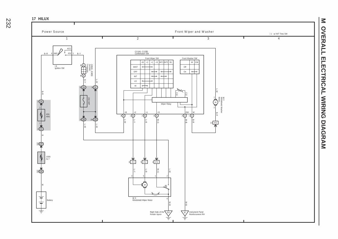
232
M O
VE
RA
LL
EL
EC
TR
ICA
L W
IRIN
G D
IAG
RA
M
3 421
17 HILUX
M
1 253
P o w e r S o u rc e F ro n t W ip e r a n d W a s h e r
BB
AB
6
B–Y
20A W
IP
2A
1AM1
B–R
2 2A
1
2
1 2G
IG1
ACC
4
26 2S
B
Battery
1 1F
B–YB–R
L–W
100AALT
1A1
W
I 6
J18 (A ), J19 (B )
L–Y
L–B
W–G
6 IF2 5 IF2 4 IF2
EARight Side of theFender Apron
W 3 4
W–B
L–W
9 2M
L–W
Instrument PanelReinforcement RH
IE
W–B
13 IF2
9
L–W
2L
B–R
2
1
M
L–W
W 2
40AAM1
Ignition SW
JunctionC
onnector
Windshield W
asherM
otor
Windshield Wiper Motor
3
L–Y
L–B
W–G
W–B
B
L–W
B1 2 B 4 B 1 A2 A
B–R
MIST
(∗1 )
(∗1 )
C11(A), C12(B)
OFF
INT
LO
+B +2 +1
HI
INT1 INT2+S B1
Off
On
W EW
Front Washer SWFront Wiper SW
+B +2 +1 +S WEW
Combination SW
Wiper Relay
∗ 1 : w/ INT Time SW
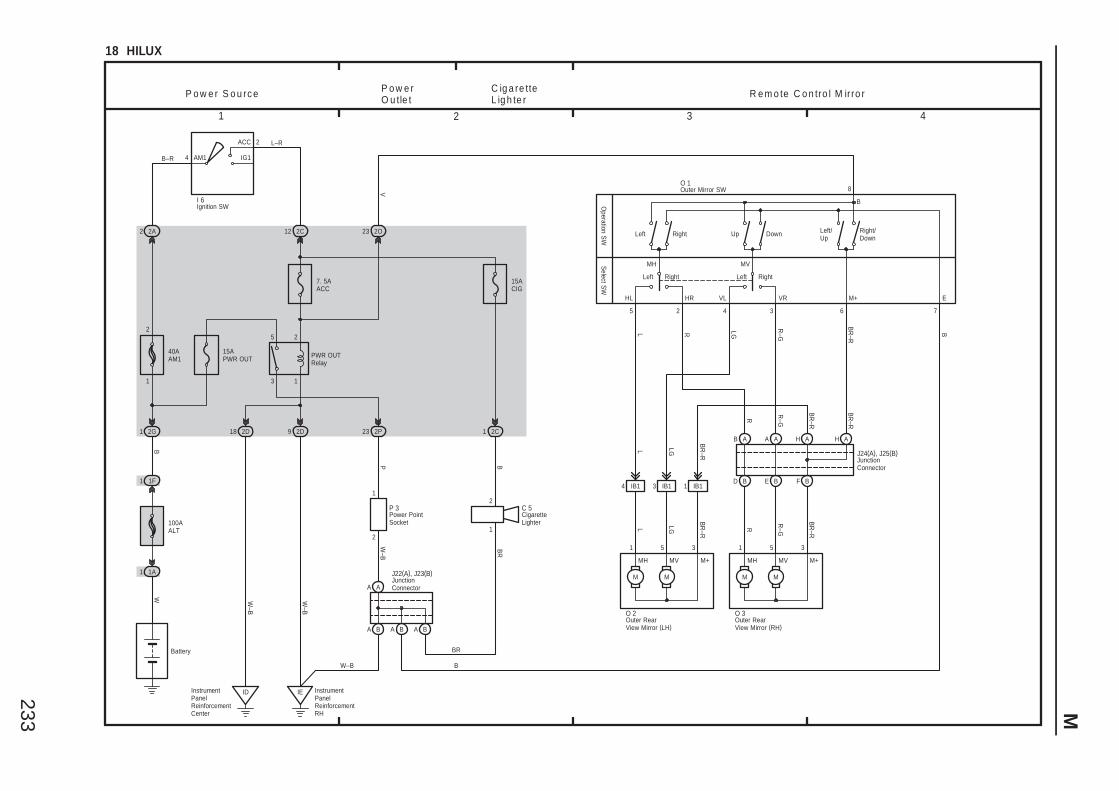
233 M
3 421
18 HILUX
5 2 4 3 6
BR
–R
R–G
LGRL
7
8
M M
MH MV M+
1 5 3
M M
MH MV M+
1 5 3
BR
–R
R–GR
BR
–R
LGL
R e m o te C o n tro l M irro rP o w e r S o u rc e
B
2
AM1
2 2A
1
2
1 2G
12
IG1
ACC
4
2C
B
40AAM1
7. 5AACC
Battery
1 1F
L–R
B–R
100AALT
1A1
W
I 6
2D92D18
IE InstrumentPanelReinforcementRH
IDInstrumentPanelReinforcementCenter
W–B
W–B
15ACIG
15APWR OUT
1
2
3
5
2O23
2P23
PWR OUTRelay
2
12
1
A A
A B A B A B
W–B
P
BR
B
2C1
W–B B
BR
C 5P 3
J22(A), J23(B)
C ig a re tteL ig h te r
P o w e rO u tle t
V
O 2 O 3
B A A A
D B E B
H A H A
F B4 IB1 3 IB1 1 IB1
BR
–R
LGL
BR
–R
BR
–R
R–GR
J24(A), J25(B)
CigaretteLighter
Ignition SW
JunctionConnector
JunctionConnector
Outer RearView Mirror (LH)
Outer RearView Mirror (RH)
Power PointSocket
VLHL HR VR M+ E
DownRight UpLeft
B
O 1
LeftLeft Right
Left/Up
Right/Down
Right
MH MV
Operation S
WS
elect SW
Outer Mirror SW
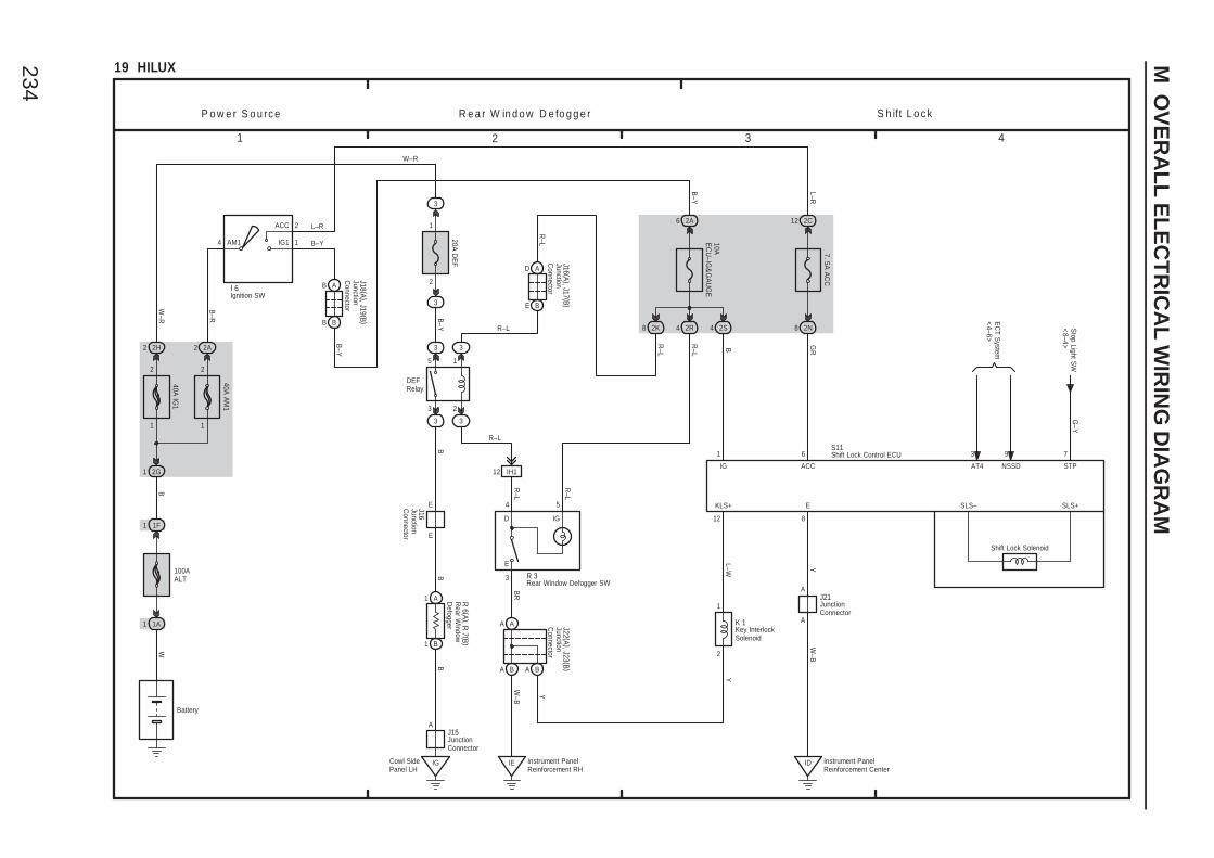
234
M O
VE
RA
LL
EL
EC
TR
ICA
L W
IRIN
G D
IAG
RA
M
3 421
19 HILUX
5
3
1
2
BB
B1
1 A
B
54
3
IE
BR
W–B
12 8
L–W
1
2
Y
1 6 7
G–Y
GR
R–L
KLS+ E
IG ACC STP
DEFRelay
S h ift L o c kR e a r W in d o w D e fo g g e rP o w e r S o u rc e
Stop Light S
W<
8–4>
IGD
E
3 3
3 3
SLS– SLS+
R–L
Instrument PanelReinforcement RH
BB
AB
2
6
1
2H2
W–R
B–Y
10AE
CU
–IG&
GA
UG
E
2A
1
2
AM1
B–R
BE
AD
2 2A
1
2
1 2G
12
IG1
ACC
4
2C
4 2R
B
40A A
M1
40A IG
1
7. 5A A
CC
Battery
1 1F
L–R
B–Y
R–L
L–R
100AALT
1A1
W
20A D
EF
3
2
1
3
B–Y
I 6
J18 (A ), J19 (B )
J16 (A ), J17 (B )
W–R
R 6 (A ), R
7 (B )
A A
A B A B
R–L
R–L
8 2K 2S4
B
12 IH1
R–L
J22 (A ), J23 (B )
R 3
K 1
S11
2N8
ID Instrument PanelReinforcement Center
Y
B–Y
Y
9
NSSD
3
AT4
EC
T System
<4–6>
J15
Cowl SidePanel LH
IG
A
E
EJ16
R–L
A
A
W–B
J21
Shift Lock Solenoid
Ignition SW
JunctionConnector
JunctionC
onnector
JunctionC
onnector
JunctionC
onnector
JunctionConnector
JunctionC
onnector
Key InterlockSolenoid
Rear Window Defogger SW
Rear W
indowD
efogger
Shift Lock Control ECU
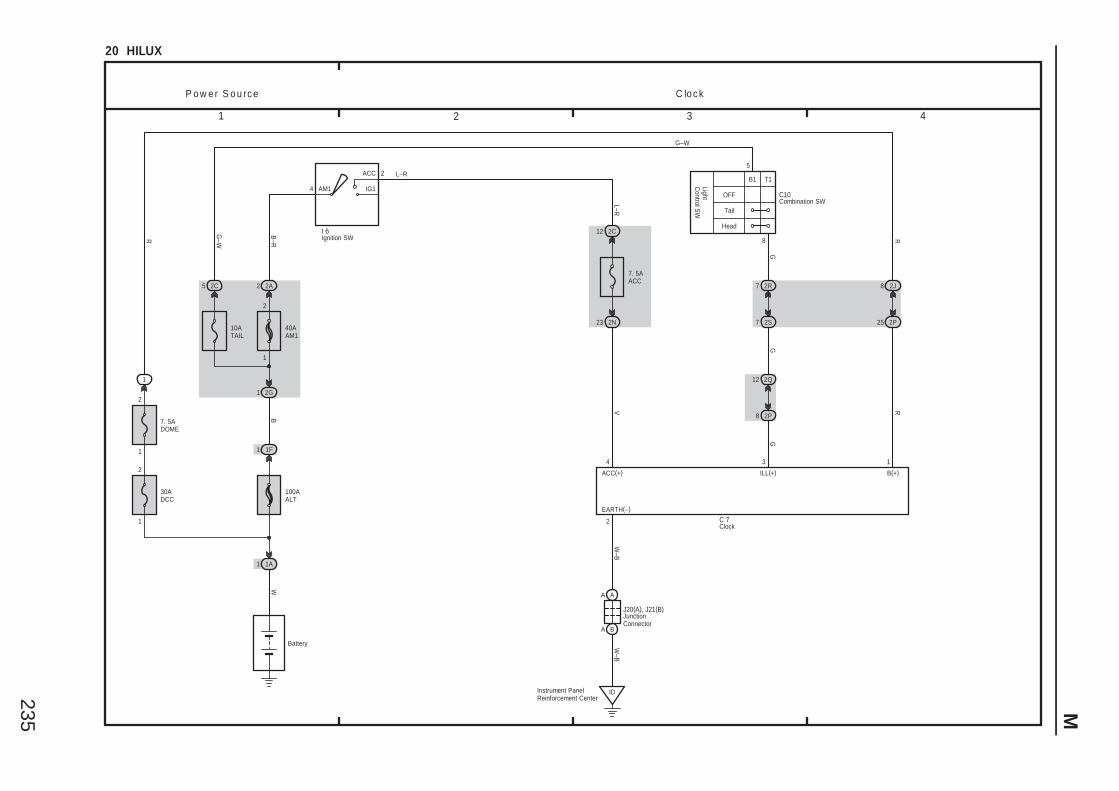
235 M
3 421
20 HILUX
W–B
2
W–B
14
EARTH(–)
B(+)ACC(+) ILL(+)
C lo c kP o w e r S o u rc e
2
AM1
B–R
2 2A
1
2
1 2G
12
IG1
ACC
4
2C
B
40AAM1
7. 5AACC
Battery
1 1F
L–R
L–R
100AALT
1A1
W
I 6
A A
A B
R
2N23
1
2
7. 5ADOME
30ADCC
2
1
1
IDInstrument PanelReinforcement Center
R
GG
G
V
C 7
J20(A), J21(B)
OFF
Tail
Head
LightC
ontrol SW
B1 T1
5
C10
10ATAIL
8 2P
2Q12
7 2S
2R7
25 2P
2J82C5
G–WR 8
G–W
3
Clock
Combination SW
Ignition SW
JunctionConnector
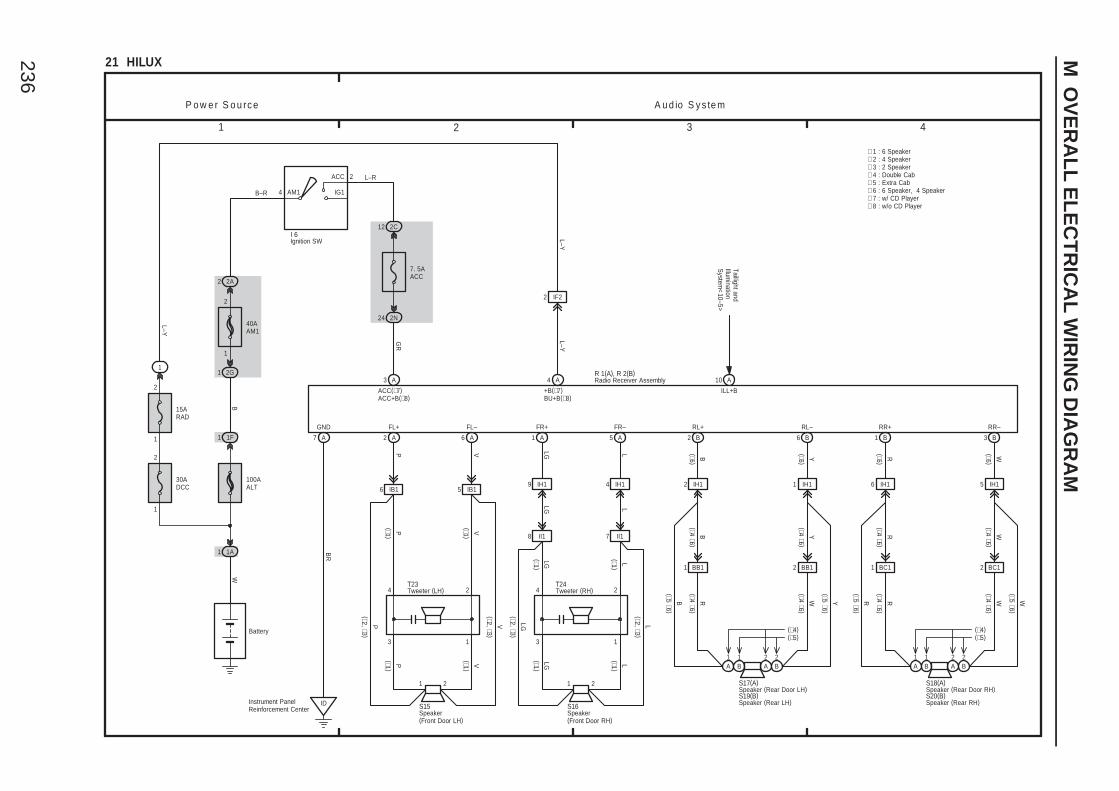
236
M O
VE
RA
LL
EL
EC
TR
ICA
L W
IRIN
G D
IAG
RA
M
3 421
BB1 BB1
21 HILUX
A3 4 A
7 A 2 A
6 IB1 5 IB1
6 A 1 A 5 A 2 B 6 B 1 B 3 B
GR
BR
P V LG L
LG L
B Y
R W
R WR W
P o w e r S o u rc e A u d io S y s te m
FR+
ACC(∗7)ACC+B(∗8)
+B(∗7)BU+B(∗8)
GND FL+ FL– FR– RL+ RL– RR+ RR–
YB
1 2
ID
LLG
1 2
L–Y
∗ 1 : 6 Speaker∗ 2 : 4 Speaker
(∗1 )
(∗1 )
Instrument PanelReinforcement Center
9 IH1 4 IH1 2 IH1 1 IH1 6 IH1 5 IH1
R W
BC1 BC11 2
S17(A) S18(A)
8 II1 7 II1
(∗1 )
(∗1 )
3 1
4 2
S16
T24
L(∗2, ∗3 )
LG(∗2, ∗3 )
LLG
3
P V1
VP
1 2
(∗1 )
(∗1 )(∗1 )
(∗1 )
4 2
S15
T23
V(∗2, ∗3 )
P(∗2, ∗3 )
1
2
15ARAD
2
AM1
2 2A
1
2
1 2G
12
IG1
ACC
4
2C
B
40AAM1
7. 5AACC
Battery
1 1F
L–R
B–R
100AALT
1A1
W
30ADCC
2
1
1
L–Y
I 6
2N24
2 IF2
L–Y
∗ 3 : 2 Speaker∗ 4 : Double Cab
R 1(A), R 2(B)
∗ 5 : Extra Cab
10 A
ILL+BTaillight andIllum
inationS
ystem<
10–5>
(∗4 ∗6 )
(∗4 ∗6 )
(∗4 ∗6 )
(∗4 ∗6 )
Y(∗5 ∗6 )
B(∗5 ∗6 )
(∗5 ∗6 )R
(∗5 ∗6 )W
(∗4 ∗6 )(∗4 ∗6 )
(∗4 ∗6 )(∗4 ∗6 )
Ignition SW
Radio Receiver Assembly
Speaker(Front Door LH)
Speaker(Front Door RH)
Tweeter (LH) Tweeter (RH)
∗ 6 : 6 Speaker, 4 Speaker
(∗6 )
(∗6 )
(∗6 )
(∗6 )
Speaker (Rear Door LH) Speaker (Rear Door RH)S19(B) S20(B)
Speaker (Rear RH)Speaker (Rear LH)
2A
2B
2A
2B
1B
1A
1B
1A
(∗4)(∗5)
(∗4)(∗5)
∗ 7 : w/ CD Player∗ 8 : w/o CD Player

237
Memo
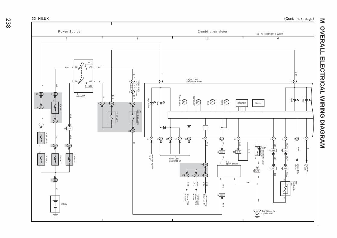
238
M O
VE
RA
LL
EL
EC
TR
ICA
L W
IRIN
G D
IAG
RA
M
1 2 3 4
22 HILUX (Cont. next page)
Interior LightSystem<11–2>
P o w e r S o u rc e C o m b in a tio n M e te r
B–OR
B–W
Headlight S
ystem<
6–3>
Speedom
eter
Tachometer
Fuel
Temp.
Door
High B
eam
1 A 21 A
27 A 17 A 16 A 7 A
Engine E
CU
<2–14>
P
4 A
Engine E
CU
<2–10>
BR
–Y
BR
A3A2
BR
BR
–Y
2
ODO/TRIP
15 A
T–BE
LT
Fuel
C 8(A), C 9(B)
V–R
6 A
Engine E
CU
<2–11>
A5
P–L
16 ID2
15 ID2
EC Rear Side of theCylinder Block
1 EA1
S 3
BR
BR
BR
R–B
P–L
1 2
3
3 BA1 4 BA1
A10
Buzzer
1
2
7. 5A D
OM
E
BB
AB
6 6
B
2C
7. 5A M
ET
B–Y
10AE
CU
–IG&
GA
UG
E
AM2 6
2A
1
B–Y
AM1
ST2
B–R
2 2A
1
2
1 2G
IG2
IG1
ACC
5
4
W–R
30 2S
B
40A A
M1
Battery
1 1F
B–YB–R
B
100A A
LT
1A1
W
30A D
CC
2
1
1
R
30A A
M2
4 1B
W–R
2J8
I 6
J18 (A ), J19 (B )
∗ 1 : w/ Theft Deterrent System
2Q25
R
2D1
B–O
2P42Q102P26
2Q26
Transmission
Control E
CU
<4–4>
V–R
Theft Warning
EC
U<
15–3>V
–R
(A/T )
(∗1 )V
–R
R–B
R–B
IF210
L–R
23 A
2
1 F10
L–R
BR
9 IA1 8 IA1
BR
–Y
BR
11 IF3
Combination Meter
Fuel Sedim
enter LevelW
arning SW
Ignition SW
Junction Connector
Speed Sensor
3
Fuel Sender
Gage
F13
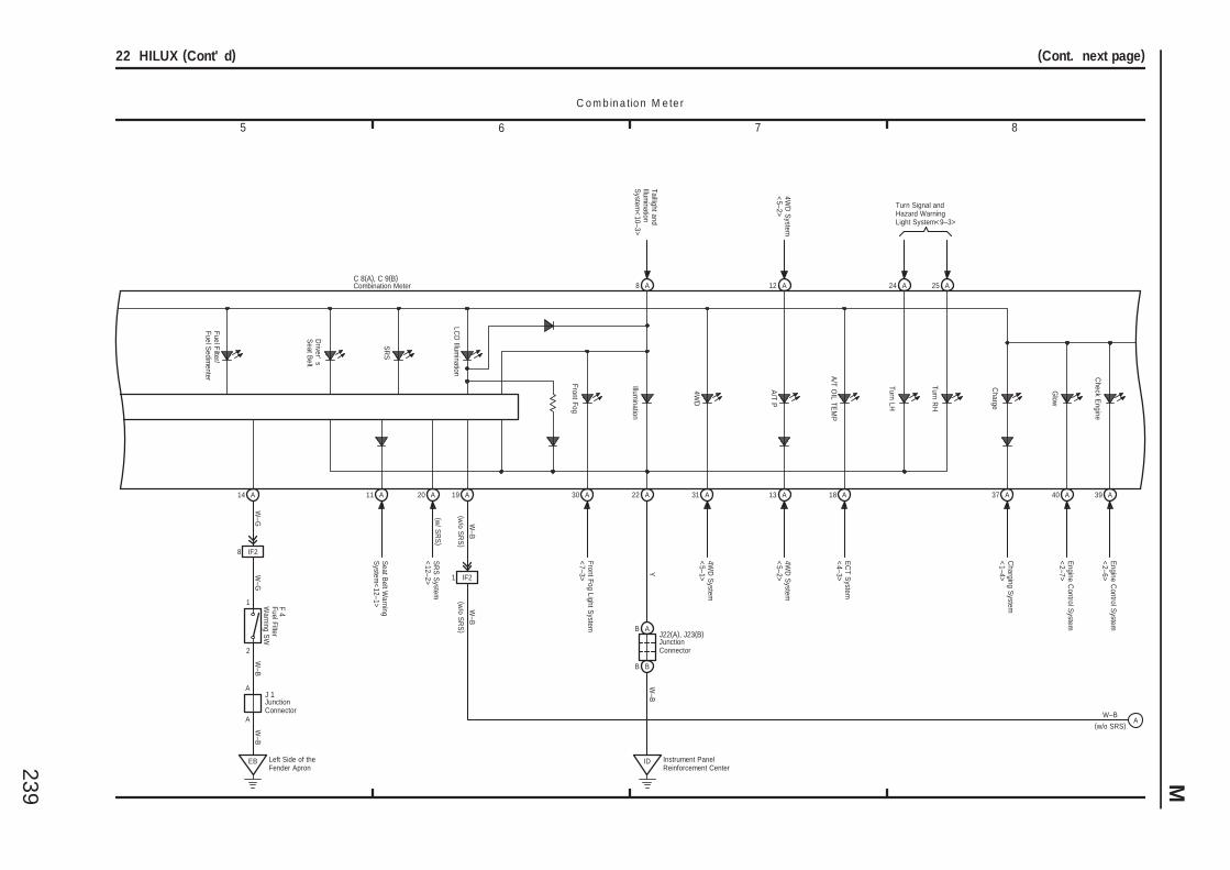
239 M
5 6 7 8
22 HILUX (Cont' d) (Cont. next page)
C o m b in a tio n M e te r
Charge
Check E
ngine
Y
Charging S
ystem<
1–4>
Engine C
ontrol System
<2–6>
Front Fog
Illumination
22 A 39 A37 A
8 AC 8(A), C 9(B)
Glow
Engine C
ontrol System
<2–7>
40 A
J22(A), J23(B)
Taillight andIllum
inationS
ystem<
10–3>
SR
S
A19
Front Fog Light System
<7–3>
30 A
Driver'
sS
eat Belt
A11
Seat B
elt Warning
System
<12–1>
A20
SR
S S
ystem<
12–2>
2
1
W–G
14 A
W–G
IF28
F 4
A25A24Turn R
H
Turn LH
Turn Signal andHazard WarningLight System<9–3>
J 1A
A
EB Left Side of theFender Apron
W–B
W–B
B A
B B
ID Instrument PanelReinforcement Center
W–B
A18
W–B
(w/o S
RS
)
1 IF2
(w/o S
RS
)W
–B
(w/o SRS)W–B
A
(w/ S
RS
)
4WD
System
<5–1>
31 A
Fuel Filter/Fuel S
edimenter
LCD
Illumination A
/T OIL TE
MP
4WD
Combination Meter
Fuel FilterW
arning SW
JunctionConnector
JunctionConnector
4WD
System
<5–2>
A12
A/T P
A13
4WD
System
<5–2>
EC
T System
<4–3>
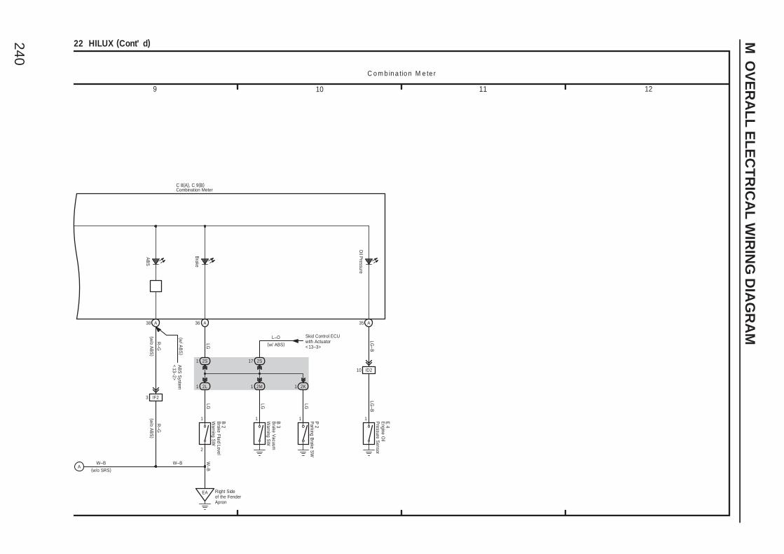
240
M O
VE
RA
LL
EL
EC
TR
ICA
L W
IRIN
G D
IAG
RA
M
9 10 11 12
22 HILUX (Cont' d)
C o m b in a tio n M e te r
AB
S
38 A
AB
S S
ystem<
13–2>
EA Right Sideof the FenderApron
2
10 ID2
LGW
–B
LG–B
LG
LG–B
LG
1 1O
il Pressure
1
36 A 35 A
C 8(A), C 9(B)
Brake
2S1 2S17
2L1 2K12M1
1
LG
(w/ ABS)L–O Skid Control ECU
with Actuator<13–3>
(w/ A
BS
)
3 IF2
R–G
R–G
W–B
(w/o A
BS
)(w
/o AB
S)
(w/o SRS)W–B
A
Combination Meter
E 4
Parking B
rake SW
P 2
B 3
Brake Fluid Level
Warning S
W
B 2
Engine O
ilP
ressure Sensor
Brake V
acuumW
arning SW
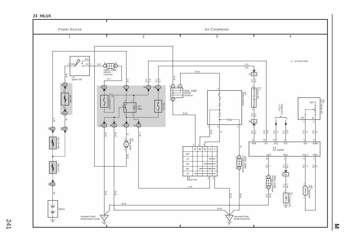
241 M
3 421
23 HILUX
2
1
G
16 IF3
10 14
1
2
78
Y–B
Y–B
L–O
R–L
P o w e r S o u rc e A ir C o n d itio n e r
2
Engine E
CU
<2–11>
SG–1 TEfin
IG+ AC1 ACT
P
Y R–L
∗ 1 : w/ Front Cooler
MGC
L–W(∗1 )
1
6 2A
1AM1
2 2A
1
2
1 2G
40A FR
HTR
IG1
ACC
4
B
40A A
M1
Battery
1 1F
B–Y
100A A
LT
1A1
W
1 1C
L–B
I 6
2D92D18
IE Instrument PanelReinforcement RH
IGInstrument PanelReinforcement Center
W–B
W–B
W–B
5
W–B
W–B
B
W–B
B 4
1
2
M
2A
B–W
L–W
1
16
L–B
HTRRelay
2D
2F
4
1
2
5
3
10AE
CU
–IG&
GA
UG
E
BA
BB
J18(A), J19(B)
2R30
R–L
P 1
A10
A 9
1 ID1
1
L–W
A 1
A A A A
A B
A A
A B
18
L–O
2P
10A A
/C
17 IF3
(∗1 )
(∗1 )(∗1 )
(∗1 )
(∗1 )
W–B
W–B
W
J22 (A ), J23 (B )
L
18
GND
W–B
J20 (A ), J21 (B )
A A
A B
5 6
B/V TEMP
V R
2
A11
B–R B
–W
(∗1)L–O
3
PSW
B–Y
(∗1 )
(∗1 )
(∗1 )
(∗1 )
(∗1 )(∗1 )
(∗1 )
(∗1 )(∗1 )
(∗1 )
J18(A), J19(B)
A/C
Com
pressor
Pressure S
W
A/C Amplifier
A/C
Thermistor
Ignition SW
JunctionConnector
JunctionConnector
Junction Connector
Junction Connector
1
E2VRT
OFF
Blow
er Motor
A/C
Volum
e SW
12 3
B 6
OFF
LO
1
M1M2 LOHI
4
M1
M2
HI
6 5
2
E
Blower SW
Blow
er Resistor
B 5
B–W
B–W
RR–B
L–W
4
![6. Wiring Diagram - weidefamily.net coil Transmission control module ... WIRING DIAGRAM 6. Wiring Diagram. MEMO: 21 WIRING DIAGRAM ... 76 6-3 [D6R2] WIRING DIAGRAM 6](https://img.pdfslide.us/doc/110x75/5aa0cc3b7f8b9a62178ea5e7/6-wiring-diagram-coil-transmission-control-module-wiring-diagram-6-wiring.jpg)
![6. Wiring Diagram - · PDF fileFB-11 Radio FB-12 Cigarette lighter FB-13 Remote control rearview mirror switch FB-14 ... WIRING DIAGRAM 6. Wiring Diagram. MEMO: 21 WIRING DIAGRAM [D6A2]](https://img.pdfslide.us/doc/110x75/5ab1b6427f8b9a00728cab2a/6-wiring-diagram-radio-fb-12-cigarette-lighter-fb-13-remote-control-rearview.jpg)
![5. Wiring Diagram - Subaru Forester. Wiring Diagram A: POWER SUPPLY ROUTING SU01-04A 12 6-3 [D5A0] WIRING DIAGRAM 5. Wiring Diagram SU01-04B 13 WIRING DIAGRAM [D5A0] 6-3 5. Wiring](https://img.pdfslide.us/doc/110x75/5aa205fe7f8b9a1f6d8cac3f/5-wiring-diagram-subaru-wiring-diagram-a-power-supply-routing-su01-04a-12.jpg)