Embed Size (px)
Citation preview

Hilti, Inc.
7250 Dallas Parkway, Suite 1000 Plano, TX 75024
1-800-879-8000
www.hil ti.com
The following excerpt are pages from the North American Product Technical Guide, Volume 2: Anchor Fastening, Edition 16.1. Please refer to the publication in its entirety for complete details on this product including data development, product specifications, general suitability, installation, corrosion and spacing and edge distance guidelines. US: http://submittals.us.hilti.com/PTGVol2/ CA: http://submittals.us.hilti.com/PTGVol2CA/ To consult directly with a team member regarding our anchor fastening products, contact Hilti’s team of technical support specialists between the hours of 7:00am – 6:00pm CST. US: 877-749-6337 or [email protected] CA: 1-800-363-4458, ext. 6 or [email protected]
Mechanical Anchoring Systems
3.3.5 KWIK Bolt TZ Expansion Anchor
268 Hilti, Inc. (US) 1-800-879-8000 | www.us.hilti.com I en español 1-800-879-5000 I Hilti (Canada) Corp. 1-800-363-4458 I www.hilti.ca I Anchor Fastening Technical Guide 2016
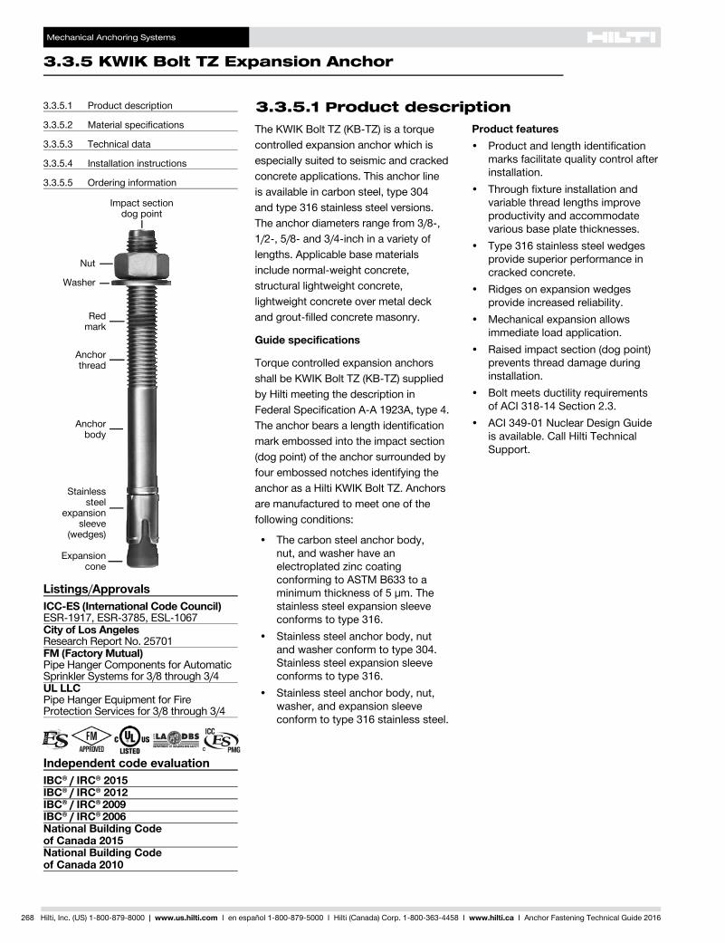
The KWIK Bolt TZ (KB-TZ) is a torque controlled expansion anchor which is especially suited to seismic and cracked concrete applications. This anchor line is available in carbon steel, type 304 and type 316 stainless steel versions. The anchor diameters range from 3/8-, 1/2-, 5/8- and 3/4-inch in a variety of lengths. Applicable base materials include normal-weight concrete, structural lightweight concrete, lightweight concrete over metal deck and grout-filled concrete masonry.
Guide specifications
Torque controlled expansion anchors shall be KWIK Bolt TZ (KB-TZ) supplied by Hilti meeting the description in Federal Specification A-A 1923A, type 4. The anchor bears a length identification mark embossed into the impact section (dog point) of the anchor surrounded by four embossed notches identifying the anchor as a Hilti KWIK Bolt TZ. Anchors are manufactured to meet one of the following conditions:
• Thecarbonsteelanchorbody, nut, and washer have an electroplated zinc coating conforming to ASTM B633 to a minimum thickness of 5 µm. The stainless steel expansion sleeve conforms to type 316.
• Stainlesssteelanchorbody,nutand washer conform to type 304. Stainless steel expansion sleeve conforms to type 316.
• Stainlesssteelanchorbody,nut,washer, and expansion sleeve conform to type 316 stainless steel.
Product features• Productandlengthidentification
marks facilitate quality control after installation.
• Throughfixtureinstallationandvariable thread lengths improve productivity and accommodate various base plate thicknesses.
• Type316stainlesssteelwedgesprovide superior performance in cracked concrete.
• Ridgesonexpansionwedges provide increased reliability.
• Mechanicalexpansionallowsimmediate load application.
• Raisedimpactsection(dogpoint)prevents thread damage during installation.
• Boltmeetsductilityrequirementsof ACI 318-14 Section 2.3.
• ACI349-01NuclearDesignGuideis available. Call Hilti Technical Support.
3.3.5.1 Product description
Listings/ApprovalsICC-ES (International Code Council)ESR-1917, ESR-3785, ESL-1067City of Los AngelesResearch Report No. 25701FM (Factory Mutual)Pipe Hanger Components for Automatic Sprinkler Systems for 3/8 through 3/4UL LLCPipe Hanger Equipment for Fire Protection Services for 3/8 through 3/4
Independent code evaluationIBC® / IRC® 2015IBC® / IRC® 2012IBC® / IRC® 2009IBC® / IRC® 2006National Building Code of Canada 2015National Building Code of Canada 2010
3.3.5.1 Product description
3.3.5.2 Material specifications
3.3.5.3 Technical data
3.3.5.4 Installation instructions
3.3.5.5 Ordering information
Impact section dog point
Nut
Washer
Red mark
Anchor body
Stainless steel
expansion sleeve
(wedges)
Anchor thread
Expansion cone
Mechanical Anchoring Systems
KWIK Bolt TZ Expansion Anchor 3.3.5
3.3.9
3.3.9
3.3.9
3.3.9
3.3.1
3.3.2
3.3.3
3.3.9
3.3.5
3.3.6
3.3.7
3.3.8
3.3.9
3.3.9
3.3.4
Hilti, Inc. (US) 1-800-879-8000 | www.us.hilti.com I en español 1-800-879-5000 I Hilti (Canada) Corp. 1-800-363-4458 I www.hilti.ca I Anchor Fastening Technical Guide 2016 269
3.3.5.2 Material specifications
Stainless steel Stainless steel KB-TZ anchors are made of type 304 or 316 material and have the following minimum bolt fracture loads.1
All nuts and washers for type 304 anchors are made from type 304 stainless.All nuts and washers for type 316 anchors are made from type 316 stainless.Nuts meet the dimensional requirements of ASTM F594.Washers meet the dimensional requirements of ANSI B18.22.1, Type A, plain.Expansion sleeve (wedges) are made from type 316 stainless steel.
1 Bolt fracture loads are determined by testing in a universal tensile machine for quality control at the manufacturing facility. These loads are not intended for design purposes. See tables 4 and 16 for the steel design strengths of carbon steel and stainless steel, respectively.
Anchor diameter(in.)
Shear(lb)
Tension(lb)
3/8 5,058 6,5191/2 8,543 12,3645/8 13,938 19,1093/4 22,481 24,729
Carbon steel with electroplated zincCarbon steel KB-TZ anchors have the following minimum bolt fracture loads.1
Carbon steel anchor components plated in accordance with ASTM B633 to a minimum thickness of 5 µm.Nuts conform to the requirements of ASTM A563, Grade A, Hex.Washers meet the requirements of ASTM F844.Expansion sleeves (wedges) are manufactured from type 316 stainless steel
Anchor diameter(in.)
Shear(lb)
Tension(lb)
3/8 NA 6,7441/2 7,419 11,2405/8 11,465 17,5353/4 17,535 25,853
The technical data contained in this section are Hilti Simplified Design Tables. The load values were developed using the Strength Design parameters and variables of ESR-1917 and the equations within ACI 318-14 Chapter 17. For a detailed explanation of the Hilti Simplified Design Tables, refer to section 3.1.8. Data tables from ESR-1917 are not contained in this section, but can be found at www.icc-es.org or at www.us.hilti.com.
3.3.5.3 Technical data
3.3.5.3.1 ACI 318-14 Chapter 17 design
Mechanical Anchoring Systems
3.3.5 KWIK Bolt TZ Expansion Anchor
270 Hilti, Inc. (US) 1-800-879-8000 | www.us.hilti.com I en español 1-800-879-5000 I Hilti (Canada) Corp. 1-800-363-4458 I www.hilti.ca I Anchor Fastening Technical Guide 2016
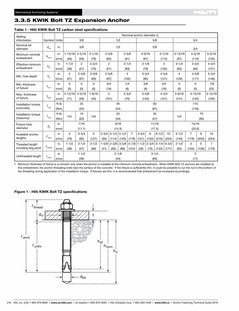
Figure 1 - Hilti KWIK Bolt TZ specifications
Table 1 - Hilti KWIK Bolt TZ carbon steel specifications
Settinginformation Symbol Units
Nominal anchor diameter do
3/8 1/2 5/8 3/4Nominal bit diameter dbit in. 3/8 1/2 5/8 3/4
Minimum nominal embedment hnom
in. 1-13/16 2-5/16 3-1/16 2-3/8 3-5/8 3-9/16 4-7/16 3-13/16 4-5/16 5-5/16(mm) (46) (59) (78) (60) (91) (91) (113) (97) (110) (135)
Effective minimum embedment hef
in. 1-1/2 2 2-3/4 2 3-1/4 3-1/8 4 3-1/4 3-3/4 4-3/4(mm) (38) (51) (70) (51) (83) (79) (102) (83) (95) (121)
Min. hole depth ho
in. 2 2-5/8 3-3/8 2-5/8 4 3-3/4 4-3/4 4 4-5/8 5-3/4(mm) (51) (67) (83) (67) (102) (95) (121) (102) (117) (146)
Min. thickness offixture1 tmin
in. 0 0 0 3/4 1/4 3/8 3/4 0 0 7/8(mm) (0) (0) (0) (19) (6) (9) (19) (0) (0) (23)
Max. thickness offixture tmax
in. 2-13/16 2-5/16 1-9/16 4 2-3/4 5-5/8 4-3/4 5-9/16 4-15/16 3-15/16(mm) (71) (59) (40) (101) (70) (143) (121) (141) (125) (100)
Installation torque (concrete) Tinst
ft-lb 25 40 60 110(Nm) (34) (54) (81) (149)
Installation torque (masonry) Tinst
ft-lbn/a
15n/a
25 35n/a
70(Nm) (20) (34) (47) (95)
Fixture hole diameter dh
in. 7/16 9/16 11/16 13/16(mm) (11.1) (14.3) (17.5) (20.6)
Available anchor lengths ℓanch
in. 3 3-3/4 5 3-3/4 4-1/2 5-1/2 7 4-3/4 6 8-1/2 10 5-1/2 7 8 10(mm) (76) (95) (127) (95) (114) (140) (178) (121) (152) (216) (254) (140) (178) (203) (254)
Threaded length including dog point ℓthread
in. 1-1/2 2-1/4 3-1/2 1-5/8 2-3/8 3-3/8 4-7/8 1-1/2 2-3/4 5-1/4 6-3/4 2-1/2 4 5 7(mm) (38) (57) (89) (41) (60) (86) (124) (38) (70) (133) (171) (63) (103) (128) (179)
Unthreaded length ℓunthr
in. 1-1/2 2-1/8 3-1/4 3(mm) (39) (54) (83) (77)
1 Minimumthicknessoffixtureisaconcernonlywhentheanchorisinstalledattheminimumnominalembedment.WhenKWIKBoltTZanchorsareinstalledatthisembedment,theanchorthreadingendsnearthesurfaceoftheconcrete.Ifthefixtureissufficientlythin,itcouldbepossibletorunthenuttothebottomofthethreadingduringapplicationoftheinstallationtorque.Iffixturesarethin,itisrecommendedthatembedmentbeincreasedaccordingly.
Mechanical Anchoring Systems
KWIK Bolt TZ Expansion Anchor 3.3.5
3.3.9
3.3.9
3.3.9
3.3.9
3.3.1
3.3.2
3.3.3
3.3.9
3.3.5
3.3.6
3.3.7
3.3.8
3.3.9
3.3.9
3.3.4
Hilti, Inc. (US) 1-800-879-8000 | www.us.hilti.com I en español 1-800-879-5000 I Hilti (Canada) Corp. 1-800-363-4458 I www.hilti.ca I Anchor Fastening Technical Guide 2016 271
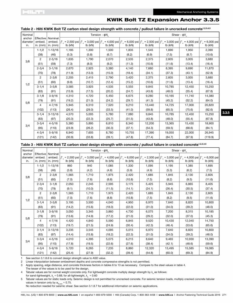
Table 2 - Hilti KWIK Bolt TZ carbon steel design strength with concrete / pullout failure in uncracked concrete1,2,3,4,5
Nominal anchor
diameter in.
Effective embed. in. (mm)
Nominal embed. in. (mm)
Tension - фNn Shear - фVn
ƒ'c = 2,500 psi lb (kN)
ƒ'c = 3,000 psi lb (kN)
ƒ'c = 4,000 psi lb (kN)
ƒ'c = 6,000 psi lb (kN)
ƒ'c = 2,500 psi lb (kN)
ƒ'c = 3,000 psi lb (kN)
ƒ'c = 4,000 psi lb (kN)
ƒ'c = 6,000 psi lb (kN)
3/8
1-1/2 1-13/16 1,185 1,300 1,500 1,835 1,545 1,690 1,950 2,390(38) (46) (5.3) (5.8) (6.7) (8.2) (6.9) (7.5) (8.7) (10.6)2 2-5/16 1,635 1,790 2,070 2,535 2,375 2,605 3,005 3,680
(51) (59) (7.3) (8.0) (9.2) (11.3) (10.6) (11.6) (13.4) (16.4)2-3/4 3-1/16 2,670 2,925 3,380 4,140 7,660 8,395 9,690 11,870(70) (78) (11.9) (13.0) (15.0) (18.4) (34.1) (37.3) (43.1) (52.8)
1/2
2 2-3/8 2,205 2,415 2,790 3,420 2,375 2,605 3,005 3,680(51) (60) (9.8) (10.7) (12.4) (15.2) (10.6) (11.6) (13.4) (16.4)
3-1/4 3-5/8 3,585 3,925 4,535 5,555 9,845 10,785 12,450 15,250(83) (91) (15.9) (17.5) (20.2) (24.7) (43.8) (48.0) (55.4) (67.8)
5/8
3-1/8 3-9/16 4,310 4,720 5,450 6,675 9,280 10,165 11,740 14,380(79) (91) (19.2) (21.0) (24.2) (29.7) (41.3) (45.2) (52.2) (64.0)4 4-7/16 5,945 6,510 7,520 9,210 13,440 14,725 17,000 20,820
(102) (113) (26.4) (29.0) (33.5) (41.0) (59.8) (65.5) (75.6) (92.6)
3/4
3-1/4 3-13/16 4,570 5,005 5,780 7,080 9,845 10,785 12,450 15,250(83) (97) (20.3) (22.3) (25.7) (31.5) (43.8) (48.0) (55.4) (67.8)
3-3/4 4-5/16 5,380 5,895 6,810 8,340 12,200 13,365 15,430 18,900(95) (110) (23.9) (26.2) (30.3) (37.1) (54.3) (59.5) (68.6) (84.1)
4-3/4 5-9/16 6,940 7,605 8,780 10,755 17,390 19,050 22,000 26,945(121) (142) (30.9) (33.8) (39.1) (47.8) (77.4) (84.7) (97.9) (119.9)
Table 3 - Hilti KWIK Bolt TZ carbon steel design strength with concrete / pullout failure in cracked concrete1,2,3,4,5
Nominal anchor
diameter in.
Effective embed. in. (mm)
Nominal embed. in. (mm)
Tension - фNn Shear - фVn
ƒ'c = 2,500 psi lb (kN)
ƒ'c = 3,000 psi lb (kN)
ƒ'c = 4,000 psi lb (kN)
ƒ'c = 6,000 psi lb (kN)
ƒ'c = 2,500 psi lb (kN)
ƒ'c = 3,000 psi lb (kN)
ƒ'c = 4,000 psi lb (kN)
ƒ'c = 6,000 psi lb (kN)
3/8
1-1/2 1-13/16 860 940 1,085 1,330 1,095 1,195 1,385 1,695(38) (46) (3.8) (4.2) (4.8) (5.9) (4.9) (5.3) (6.2) (7.5)2 2-3/8 1,565 1,710 1,975 2,420 1,685 1,845 2,130 2,605
(51) (60) (7.0) (7.6) (8.8) (10.8) (7.5) (8.2) (9.5) (11.6)2-3/4 3-1/8 2,050 2,245 2,595 3,175 5,425 5,945 6,865 8,405(70) (79) (9.1) (10.0) (11.5) (14.1) (24.1) (26.4) (30.5) (37.4)
1/2
2 2-3/8 1,565 1,710 1,975 2,420 1,685 1,845 2,130 2,605(51) (60) (7.0) (7.6) (8.8) (10.8) (7.5) (8.2) (9.5) (11.6)
3-1/4 3-5/8 3,195 3,500 4,040 4,950 6,970 7,640 8,820 10,800(83) (91) (14.2) (15.6) (18.0) (22.0) (31.0) (34.0) (39.2) (48.0)
5/8
3-1/8 3-9/16 3,050 3,345 3,860 4,730 6,575 7,200 8,315 10,185(79) (91) (13.6) (14.9) (17.2) (21.0) (29.2) (32.0) (37.0) (45.3)4 4-7/16 4,420 4,840 5,590 6,845 9,520 10,430 12,040 14,750
(102) (113) (19.7) (21.5) (24.9) (30.4) (42.3) (46.4) (53.6) (65.6)
3/4
3-1/4 3-13/16 3,235 3,545 4,095 5,015 6,970 7,640 8,820 10,800(83) (97) (14.4) (15.8) (18.2) (22.3) (31.0) (34.0) (39.2) (48.0)
3-3/4 4-5/16 4,010 4,395 5,075 6,215 8,640 9,465 10,930 13,390(95) (110) (17.8) (19.5) (22.6) (27.6) (38.4) (42.1) (48.6) (59.6)
4-3/4 5-9/16 5,720 6,265 7,235 8,860 12,320 13,495 15,585 19,085(121) (142) (25.4) (27.9) (32.2) (39.4) (54.8) (60.0) (69.3) (84.9)
1 See section 3.1.8.6 to convert design strength value to ASD value.2 Linear interpolation between embedment depths and concrete compressive strengths is not permitted.3 Apply spacing, edge distance, and concrete thickness factors in tables 6 to 13 as necessary. Compare to the steel values in table 4.
The lesser of the values is to be used for the design.4 Tabularvaluesarefornormalweightconcreteonly.Forlightweightconcretemultiplydesignstrengthbyλa as follows:
forsand-lightweight,λa=0.68;forall-lightweight,λa = 0.605 Tabular values are for static loads only. Seismic design is not permitted for uncracked concrete. For seismic tension loads, multiply cracked concrete tabular
valuesintensiononlybyαN,seis = 0.75. No reduction needed for seismic shear. See section 3.1.8.7 for additional information on seismic applications.
Mechanical Anchoring Systems
3.3.5 KWIK Bolt TZ Expansion Anchor
272 Hilti, Inc. (US) 1-800-879-8000 | www.us.hilti.com I en español 1-800-879-5000 I Hilti (Canada) Corp. 1-800-363-4458 I www.hilti.ca I Anchor Fastening Technical Guide 2016
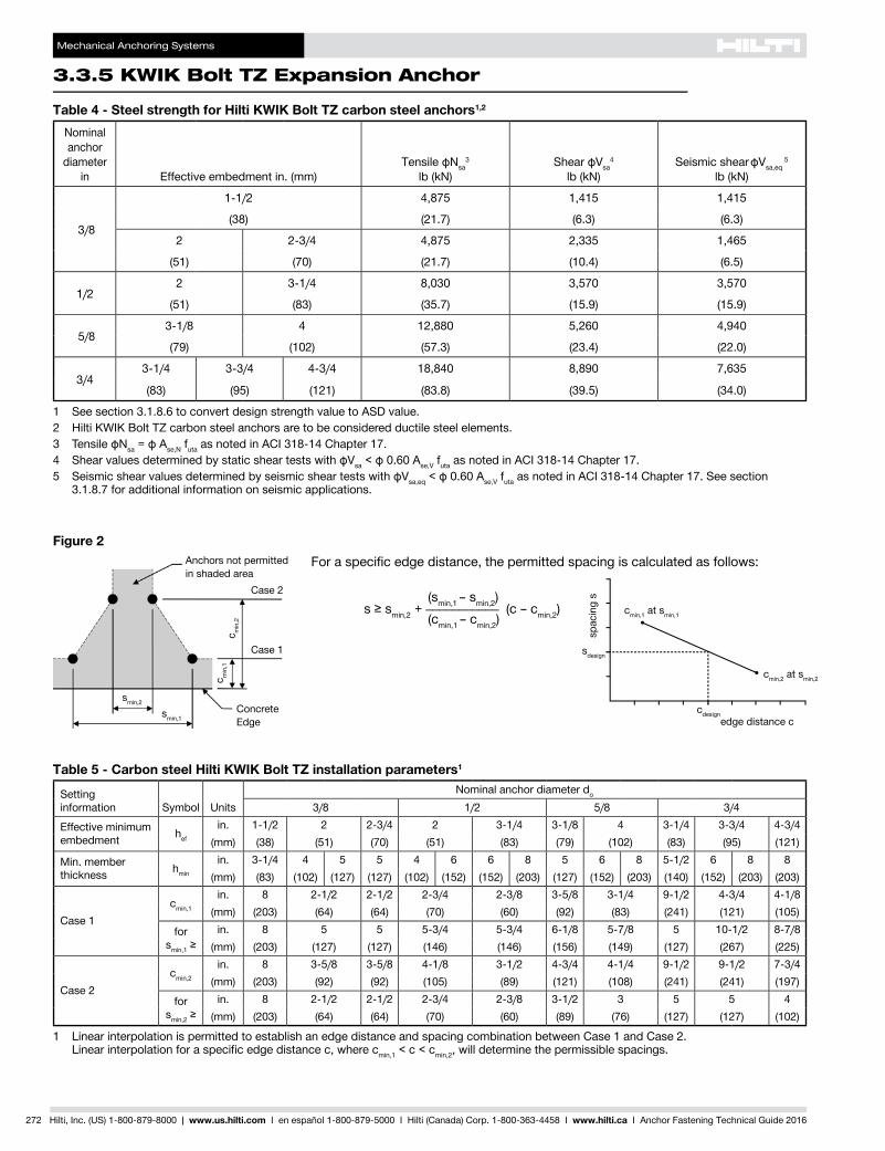
For a specific edge distance, the permitted spacing is calculated as follows:
(smin,1 – smin,2) s≥smin,2 + ___________ (c – cmin,2) (cmin,1 – cmin,2)
cdesignedge distance c
cmin,1 at smin,1
cmin,2 at smin,2
sdesign
spac
ing
s
Figure 2
Concrete Edge
Anchors not permitted in shaded area
smin,2
smin,1
c min
,1c m
in,2
Case 1
Case 2
Table 5 - Carbon steel Hilti KWIK Bolt TZ installation parameters1
Settinginformation Symbol Units
Nominal anchor diameter do
3/8 1/2 5/8 3/4
Effective minimum embedment hef
in. 1-1/2 2 2-3/4 2 3-1/4 3-1/8 4 3-1/4 3-3/4 4-3/4(mm) (38) (51) (70) (51) (83) (79) (102) (83) (95) (121)
Min. member thickness hmin
in. 3-1/4 4 5 5 4 6 6 8 5 6 8 5-1/2 6 8 8(mm) (83) (102) (127) (127) (102) (152) (152) (203) (127) (152) (203) (140) (152) (203) (203)
Case 1cmin,1
in. 8 2-1/2 2-1/2 2-3/4 2-3/8 3-5/8 3-1/4 9-1/2 4-3/4 4-1/8(mm) (203) (64) (64) (70) (60) (92) (83) (241) (121) (105)
for smin,1≥
in. 8 5 5 5-3/4 5-3/4 6-1/8 5-7/8 5 10-1/2 8-7/8(mm) (203) (127) (127) (146) (146) (156) (149) (127) (267) (225)
Case 2cmin,2
in. 8 3-5/8 3-5/8 4-1/8 3-1/2 4-3/4 4-1/4 9-1/2 9-1/2 7-3/4(mm) (203) (92) (92) (105) (89) (121) (108) (241) (241) (197)
for smin,2≥
in. 8 2-1/2 2-1/2 2-3/4 2-3/8 3-1/2 3 5 5 4(mm) (203) (64) (64) (70) (60) (89) (76) (127) (127) (102)
1 Linear interpolation is permitted to establish an edge distance and spacing combination between Case 1 and Case 2. Linearinterpolationforaspecificedgedistancec,wherecmin,1 < c < cmin,2, will determine the permissible spacings.
Table 4 - Steel strength for Hilti KWIK Bolt TZ carbon steel anchors1,2
Nominal anchor
diameter in Effective embedment in. (mm)
Tensile фNsa3
lb (kN)Shear фVsa
4
lb (kN)Seismic shear фVsa,eq
5
lb (kN)
3/8
1-1/2 4,875 1,415 1,415
(38) (21.7) (6.3) (6.3)
2 2-3/4 4,875 2,335 1,465
(51) (70) (21.7) (10.4) (6.5)
1/22 3-1/4 8,030 3,570 3,570
(51) (83) (35.7) (15.9) (15.9)
5/83-1/8 4 12,880 5,260 4,940
(79) (102) (57.3) (23.4) (22.0)
3/43-1/4 3-3/4 4-3/4 18,840 8,890 7,635
(83) (95) (121) (83.8) (39.5) (34.0)
1 See section 3.1.8.6 to convert design strength value to ASD value.2 Hilti KWIK Bolt TZ carbon steel anchors are to be considered ductile steel elements.3 TensileфNsa=фAse,N futa as noted in ACI 318-14 Chapter 17.4 ShearvaluesdeterminedbystaticsheartestswithфVsa<ф0.60Ase,V futa as noted in ACI 318-14 Chapter 17.5 SeismicshearvaluesdeterminedbyseismicsheartestswithфVsa,eq<ф0.60Ase,V futa as noted in ACI 318-14 Chapter 17. See section
3.1.8.7 for additional information on seismic applications.
Mechanical Anchoring Systems
KWIK Bolt TZ Expansion Anchor 3.3.5
3.3.9
3.3.9
3.3.9
3.3.9
3.3.1
3.3.2
3.3.3
3.3.9
3.3.5
3.3.6
3.3.7
3.3.8
3.3.9
3.3.9
3.3.4
Hilti, Inc. (US) 1-800-879-8000 | www.us.hilti.com I en español 1-800-879-5000 I Hilti (Canada) Corp. 1-800-363-4458 I www.hilti.ca I Anchor Fastening Technical Guide 2016 273
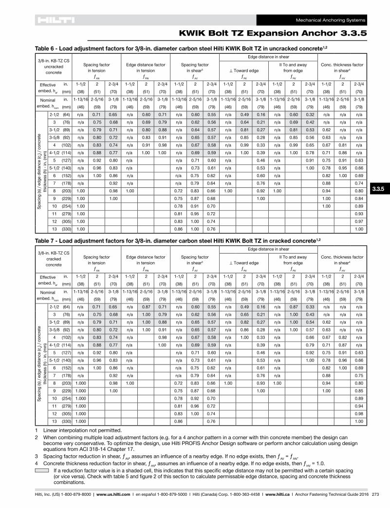
Table 6 - Load adjustment factors for 3/8-in. diameter carbon steel Hilti KWIK Bolt TZ in uncracked concrete1,2
3/8-in. KB-TZ CS uncracked concrete
Spacing factor in tension
ƒAN
Edge distance factor in tension
ƒRN
Spacing factor in shear3
ƒAV
Edge distance in shear
Conc. thickness factor in shear4
ƒHV
⊥Toward edgeƒRV
II To and away from edge
ƒRV
Effective embed. hef
in. 1-1/2 2 2-3/4 1-1/2 2 2-3/4 1-1/2 2 2-3/4 1-1/2 2 2-3/4 1-1/2 2 2-3/4 1-1/2 2 2-3/4
(mm) (38) (51) (70) (38) (51) (70) (38) (51) (70) (38) (51) (70) (38) (51) (70) (38) (51) (70)
Nominal embed. hnom
in. 1-13/16 2-5/16 3-1/8 1-13/16 2-5/16 3-1/8 1-13/16 2-5/16 3-1/8 1-13/16 2-5/16 3-1/8 1-13/16 2-5/16 3-1/8 1-13/16 2-5/16 3-1/8
(mm) (46) (59) (79) (46) (59) (79) (46) (59) (79) (46) (59) (79) (46) (59) (79) (46) (59) (79)
Spac
ing
(s) /
edg
e di
stan
ce (c
a) / c
oncr
ete
thic
knes
s (h
) - in
. (m
m)
2-1/2 (64) n/a 0.71 0.65 n/a 0.60 0.71 n/a 0.60 0.55 n/a 0.49 0.16 n/a 0.60 0.32 n/a n/a n/a
3 (76) n/a 0.75 0.68 n/a 0.69 0.79 n/a 0.62 0.56 n/a 0.64 0.21 n/a 0.69 0.42 n/a n/a n/a
3-1/2 (89) n/a 0.79 0.71 n/a 0.80 0.88 n/a 0.64 0.57 n/a 0.81 0.27 n/a 0.81 0.53 0.62 n/a n/a
3-5/8 (92) n/a 0.80 0.72 n/a 0.83 0.91 n/a 0.65 0.57 n/a 0.85 0.28 n/a 0.85 0.56 0.63 n/a n/a
4 (102) n/a 0.83 0.74 n/a 0.91 0.98 n/a 0.67 0.58 n/a 0.99 0.33 n/a 0.99 0.65 0.67 0.81 n/a
4-1/2 (114) n/a 0.88 0.77 n/a 1.00 1.00 n/a 0.69 0.59 n/a 1.00 0.39 n/a 1.00 0.78 0.71 0.86 n/a
5 (127) n/a 0.92 0.80 n/a n/a 0.71 0.60 n/a 0.46 n/a 0.91 0.75 0.91 0.63
5-1/2 (140) n/a 0.96 0.83 n/a n/a 0.73 0.61 n/a 0.53 n/a 1.00 0.78 0.95 0.66
6 (152) n/a 1.00 0.86 n/a n/a 0.75 0.62 n/a 0.60 n/a 0.82 1.00 0.69
7 (178) n/a 0.92 n/a n/a 0.79 0.64 n/a 0.76 n/a 0.88 0.74
8 (203) 1.00 0.98 1.00 0.72 0.83 0.66 1.00 0.92 1.00 0.94 0.80
9 (229) 1.00 1.00 0.75 0.87 0.68 1.00 1.00 0.84
10 (254) 1.00 0.78 0.91 0.70 1.00 0.89
11 (279) 1.00 0.81 0.95 0.72 0.93
12 (305) 1.00 0.83 1.00 0.74 0.97
13 (330) 1.00 0.86 1.00 0.76 1.00
Table 7 - Load adjustment factors for 3/8-in. diameter carbon steel Hilti KWIK Bolt TZ in cracked concrete1,2
3/8-in. KB-TZ CS cracked concrete
Spacing factor in tension
ƒAN
Edge distance factor in tension
ƒRN
Spacing factor in shear3
ƒAV
Edge distance in shear
Conc. thickness factor in shear4
ƒHV
⊥Toward edgeƒRV
II To and away from edge
ƒRV
Effective embed. hef
in. 1-1/2 2 2-3/4 1-1/2 2 2-3/4 1-1/2 2 2-3/4 1-1/2 2 2-3/4 1-1/2 2 2-3/4 1-1/2 2 2-3/4
(mm) (38) (51) (70) (38) (51) (70) (38) (51) (70) (38) (51) (70) (38) (51) (70) (38) (51) (70)
Nominal embed. hnom
in. 1-13/16 2-5/16 3-1/8 1-13/16 2-5/16 3-1/8 1-13/16 2-5/16 3-1/8 1-13/16 2-5/16 3-1/8 1-13/16 2-5/16 3-1/8 1-13/16 2-5/16 3-1/8
(mm) (46) (59) (79) (46) (59) (79) (46) (59) (79) (46) (59) (79) (46) (59) (79) (46) (59) (79)
Spac
ing
(s) /
edg
e di
stan
ce (c
a) / c
oncr
ete
thic
knes
s (h
) - in
. (m
m)
2-1/2 (64) n/a 0.71 0.65 n/a 0.87 0.71 n/a 0.60 0.55 n/a 0.49 0.16 n/a 0.87 0.33 n/a n/a n/a
3 (76) n/a 0.75 0.68 n/a 1.00 0.79 n/a 0.62 0.56 n/a 0.65 0.21 n/a 1.00 0.43 n/a n/a n/a
3-1/2 (89) n/a 0.79 0.71 n/a 1.00 0.88 n/a 0.65 0.57 n/a 0.82 0.27 n/a 1.00 0.54 0.62 n/a n/a
3-5/8 (92) n/a 0.80 0.72 n/a 1.00 0.91 n/a 0.65 0.57 n/a 0.86 0.28 n/a 1.00 0.57 0.63 n/a n/a
4 (102) n/a 0.83 0.74 n/a 0.98 n/a 0.67 0.58 n/a 1.00 0.33 n/a 0.66 0.67 0.82 n/a
4-1/2 (114) n/a 0.88 0.77 n/a 1.00 n/a 0.69 0.59 n/a 0.39 n/a 0.79 0.71 0.87 n/a
5 (127) n/a 0.92 0.80 n/a n/a 0.71 0.60 n/a 0.46 n/a 0.92 0.75 0.91 0.63
5-1/2 (140) n/a 0.96 0.83 n/a n/a 0.73 0.61 n/a 0.53 n/a 1.00 0.78 0.96 0.66
6 (152) n/a 1.00 0.86 n/a n/a 0.75 0.62 n/a 0.61 n/a 0.82 1.00 0.69
7 (178) n/a 0.92 n/a n/a 0.79 0.64 n/a 0.76 n/a 0.88 0.75
8 (203) 1.000 0.98 1.00 0.72 0.83 0.66 1.00 0.93 1.00 0.94 0.80
9 (229) 1.000 1.00 0.75 0.87 0.68 1.00 1.00 0.85
10 (254) 1.000 0.78 0.92 0.70 0.89
11 (279) 1.000 0.81 0.96 0.72 0.94
12 (305) 1.000 0.83 1.00 0.74 0.98
13 (330) 1.000 0.86 0.76 1.00
1 Linear interpolation not permitted.2 When combining multiple load adjustment factors (e.g. for a 4 anchor pattern in a corner with thin concrete member) the design can
become very conservative. To optimize the design, use Hilti PROFIS Anchor Design software or perform anchor calculation using design equations from ACI 318-14 Chapter 17.
3 Spacing factor reduction in shear, ƒAV,assumesaninfluenceofanearbyedge.Ifnoedgeexists,thenƒAV = ƒAN.4 Concrete thickness reduction factor in shear, ƒHV,assumesaninfluenceofanearbyedge.Ifnoedgeexists,thenƒHV = 1.0.
Ifareductionfactorvalueisinashadedcell,thisindicatesthatthisspecificedgedistancemaynotbepermittedwithacertainspacing(orviceversa).Checkwithtable5andfigure2ofthissectiontocalculatepermissableedgedistance,spacingandconcretethicknesscombinations.
Mechanical Anchoring Systems
3.3.5 KWIK Bolt TZ Expansion Anchor
274 Hilti, Inc. (US) 1-800-879-8000 | www.us.hilti.com I en español 1-800-879-5000 I Hilti (Canada) Corp. 1-800-363-4458 I www.hilti.ca I Anchor Fastening Technical Guide 2016
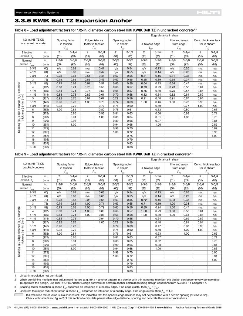
Table 8 - Load adjustment factors for 1/2-in. diameter carbon steel Hilti KWIK Bolt TZ in uncracked concrete1,2
1/2-in. KB-TZ CS uncracked concrete
Spacing factor in tension
ƒAN
Edge distance factor in tension
ƒRN
Spacing factor in shear3
ƒAV
Edge distance in shear
Conc. thickness fac-tor in shear4
ƒHV
⊥toward edgeƒRV
II to and away from edge
ƒRV
Effective embed. hef
in. 2 3-1/4 2 3-1/4 2 3-1/4 2 3-1/4 2 3-1/4 2 3-1/4(mm) (51) (83) (51) (83) (51) (83) (51) (83) (51) (83) (51) (83)
Nominal embed. hnom
in. 2-3/8 3-5/8 2-3/8 3-5/8 2-3/8 3-5/8 2-3/8 3-5/8 2-3/8 3-5/8 2-3/8 3-5/8(mm) (60) (92) (60) (92) (60) (92) (60) (92) (60) (92) (60) (92)
Spac
ing
(s) /
edg
e di
stan
ce (c
a) / c
oncr
ete
thic
knes
s (h
) - in
. (m
m)
2-3/8 (60) n/a 0.62 n/a 0.41 n/a 0.54 n/a 0.13 n/a 0.26 n/a n/a2-1/2 (64) n/a 0.63 n/a 0.42 n/a 0.55 n/a 0.14 n/a 0.28 n/a n/a2-3/4 (70) 0.73 0.64 0.51 0.44 0.62 0.55 0.51 0.16 0.51 0.33 n/a n/a
3 (76) 0.75 0.65 0.55 0.46 0.63 0.55 0.55 0.19 0.55 0.37 n/a n/a3-1/2 (89) 0.79 0.68 0.64 0.51 0.65 0.56 0.64 0.23 0.64 0.47 n/a n/a
4 (102) 0.83 0.71 0.73 0.56 0.68 0.57 0.73 0.29 0.73 0.56 0.84 n/a4-1/8 (105) 0.84 0.71 0.75 0.57 0.68 0.57 0.75 0.30 0.75 0.57 0.85 n/a4-1/2 (114) 0.88 0.73 0.82 0.61 0.70 0.58 0.82 0.34 0.82 0.61 0.89 n/a
5 (127) 0.92 0.76 0.91 0.67 0.72 0.59 0.91 0.40 0.91 0.67 0.94 n/a5-1/2 (140) 0.96 0.78 1.00 0.73 0.74 0.60 1.00 0.46 1.00 0.73 0.98 n/a5-3/4 (146) 0.98 0.79 0.77 0.75 0.60 0.49 0.77 1.00 n/a
6 (152) 1.00 0.81 0.80 0.76 0.61 0.53 0.80 0.667 (178) 0.86 0.93 0.81 0.63 0.66 0.93 0.718 (203) 0.91 1.00 0.85 0.64 0.81 1.00 0.769 (229) 0.96 0.89 0.66 0.97 0.81
10 (254) 1.00 0.94 0.68 1.00 0.8511 (279) 0.98 0.70 0.8912 (305) 1.00 0.72 0.9314 (356) 0.75 1.0016 (406) 0.7918 (457) 0.83
> 20 (508) 0.86
Table 9 - Load adjustment factors for 1/2-in. diameter carbon steel Hilti KWIK Bolt TZ in cracked concrete1,2
1/2-in. KB-TZ CS cracked concrete
Spacing factor in tension
ƒAN
Edge distance factor in tension
ƒRN
Spacing factor in shear3
ƒAV
Edge distance in shear
Conc. thickness fac-tor in shear4
ƒHV
⊥toward edgeƒRV
II to and away from edge
ƒRV
Effective embed. hef
in. 2 3-1/4 2 3-1/4 2 3-1/4 2 3-1/4 2 3-1/4 2 3-1/4(mm) (51) (83) (51) (83) (51) (83) (51) (83) (51) (83) (51) (83)
Nominal embed. hnom
in. 2-3/8 3-5/8 2-3/8 3-5/8 2-3/8 3-5/8 2-3/8 3-5/8 2-3/8 3-5/8 2-3/8 3-5/8(mm) (60) (92) (60) (92) (60) (92) (60) (92) (60) (92) (60) (92)
Spac
ing
(s) /
edg
e di
stan
ce (c
a) / c
oncr
ete
thic
knes
s (h
) - in
. (m
m)
2-3/8 (60) n/a 0.62 n/a 0.63 n/a 0.54 n/a 0.13 n/a 0.26 n/a n/a2-1/2 (64) n/a 0.63 n/a 0.65 n/a 0.55 n/a 0.14 n/a 0.29 n/a n/a2-3/4 (70) 0.73 0.64 0.93 0.68 0.62 0.55 0.62 0.16 0.93 0.33 n/a n/a
3 (76) 0.75 0.65 1.00 0.71 0.63 0.55 0.71 0.19 1.00 0.38 n/a n/a3-1/2 (89) 0.79 0.68 1.00 0.79 0.65 0.56 0.89 0.24 1.00 0.47 n/a n/a
4 (102) 0.83 0.71 1.00 0.86 0.68 0.57 1.00 0.29 1.00 0.58 0.84 n/a4-1/8 (105) 0.84 0.71 1.00 0.88 0.68 0.58 1.00 0.30 1.00 0.61 0.85 n/a4-1/2 (114) 0.88 0.73 0.94 0.70 0.58 0.34 0.69 0.89 n/a
5 (127) 0.92 0.76 1.00 0.72 0.59 0.40 0.81 0.94 n/a5-1/2 (140) 0.96 0.78 0.74 0.60 0.47 0.93 0.98 n/a5-3/4 (146) 0.98 0.79 0.75 0.60 0.50 1.00 1.00 n/a
6 (152) 1.00 0.81 0.76 0.61 0.53 1.00 0.667 (178) 0.86 0.81 0.63 0.67 0.718 (203) 0.91 0.85 0.65 0.82 0.769 (229) 0.96 0.90 0.66 0.98 0.81
10 (254) 1.00 0.94 0.68 1.00 0.8511 (279) 0.98 0.70 0.9012 (305) 1.00 0.72 0.9414 (356) 0.76 1.0016 (406) 0.7918 (457) 0.83
> 20 (508) 0.861 Linear interpolation not permitted.2 When combining multiple load adjustment factors (e.g. for a 4 anchor pattern in a corner with thin concrete member) the design can become very conservative.
To optimize the design, use Hilti PROFIS Anchor Design software or perform anchor calculation using design equations from ACI 318-14 Chapter 17.3 Spacing factor reduction in shear, ƒAV,assumesaninfluenceofanearbyedge.Ifnoedgeexists,thenƒAV = ƒAN.4 Concrete thickness reduction factor in shear, ƒHV,assumesaninfluenceofanearbyedge.Ifnoedgeexists,thenƒHV = 1.0.
Ifareductionfactorvalueisinashadedcell,thisindicatesthatthisspecificedgedistancemaynotbepermittedwithacertainspacing(orviceversa). Checkwithtable5andfigure2ofthissectiontocalculatepermissableedgedistance,spacingandconcretethicknesscombinations.
Mechanical Anchoring Systems
KWIK Bolt TZ Expansion Anchor 3.3.5
3.3.9
3.3.9
3.3.9
3.3.9
3.3.1
3.3.2
3.3.3
3.3.9
3.3.5
3.3.6
3.3.7
3.3.8
3.3.9
3.3.9
3.3.4
Hilti, Inc. (US) 1-800-879-8000 | www.us.hilti.com I en español 1-800-879-5000 I Hilti (Canada) Corp. 1-800-363-4458 I www.hilti.ca I Anchor Fastening Technical Guide 2016 275
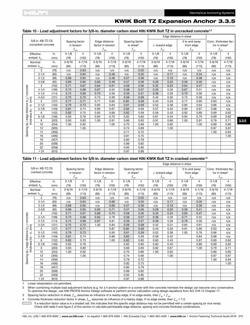
Table 10 - Load adjustment factors for 5/8-in. diameter carbon steel Hilti KWIK Bolt TZ in uncracked concrete1,2
5/8-in. KB-TZ CS uncracked concrete
Spacing factor in tension
ƒAN
Edge distance factor in tension
ƒRN
Spacing factor in shear3
ƒAV
Edge distance in shear
Conc. thickness fac-tor in shear4
ƒHV
⊥toward edgeƒRV
II to and away from edge
ƒRV
Effective embed. hef
in. 3-1/8 4 3-1/8 4 3-1/8 4 3-1/8 4 3-1/8 4 3-1/8 4(mm) (79) (102) (79) (102) (79) (102) (79) (102) (79) (102) (79) (102)
Nominal embed. hnom
in. 3-9/16 4-7/16 3-9/16 4-7/16 3-9/16 4-7/16 3-9/16 4-7/16 3-9/16 4-7/16 3-9/16 4-7/16(mm) (90) (113) (90) (113) (90) (113) (90) (113) (90) (113) (90) (113)
Spac
ing
(s) /
edg
e di
stan
ce (c
a) / c
oncr
ete
thic
knes
s (h
) - in
. (m
m)
3 (76) n/a 0.63 n/a n/a n/a 0.55 n/a n/a n/a n/a n/a n/a3-1/4 (83) n/a 0.64 n/a 0.46 n/a 0.55 n/a 0.17 n/a 0.34 n/a n/a3-1/2 (89) 0.69 0.65 n/a 0.48 0.57 0.56 n/a 0.19 n/a 0.38 n/a n/a3-5/8 (92) 0.69 0.65 0.60 0.48 0.57 0.56 0.28 0.20 0.56 0.40 n/a n/a
4 (102) 0.71 0.67 0.64 0.51 0.58 0.56 0.32 0.23 0.64 0.47 n/a n/a4-1/4 (108) 0.73 0.68 0.67 0.53 0.58 0.57 0.35 0.26 0.67 0.51 n/a n/a4-1/2 (114) 0.74 0.69 0.70 0.56 0.59 0.57 0.38 0.28 0.70 0.56 n/a n/a4-3/4 (121) 0.75 0.70 0.73 0.58 0.59 0.58 0.42 0.30 0.73 0.58 n/a n/a
5 (127) 0.77 0.71 0.77 0.60 0.60 0.58 0.45 0.33 0.77 0.60 0.63 n/a5-1/2 (140) 0.79 0.73 0.85 0.64 0.61 0.59 0.52 0.38 0.85 0.64 0.66 n/a5-7/8 (149) 0.81 0.74 0.90 0.67 0.62 0.59 0.57 0.42 0.90 0.67 0.68 n/a
6 (152) 0.82 0.75 0.92 0.69 0.62 0.59 0.59 0.43 0.92 0.69 0.69 0.626-1/8 (156) 0.83 0.76 0.94 0.70 0.62 0.60 0.61 0.44 0.94 0.70 0.69 0.62
8 (203) 0.93 0.83 1.00 0.91 0.66 0.63 0.91 0.66 1.00 0.91 0.79 0.7110 (254) 1.00 0.92 1.00 0.70 0.66 1.00 0.92 1.00 0.89 0.8012 (305) 1.00 0.74 0.69 1.00 0.97 0.8714 (356) 0.77 0.72 1.00 0.9416 (406) 0.81 0.75 1.0018 (457) 0.85 0.7820 (508) 0.89 0.8222 (559) 0.93 0.85
> 24 (610) 0.97 0.88
Table 11 - Load adjustment factors for 5/8-in. diameter carbon steel Hilti KWIK Bolt TZ in cracked concrete1,2
5/8-in. KB-TZ CS cracked concrete
Spacing factor in tension
ƒAN
Edge distance factor in tension
ƒRN
Spacing factor in shear3
ƒAV
Edge distance in shear
Conc. thickness fac-tor in shear4
ƒHV
⊥toward edgeƒRV
II to and away from edge
ƒRV
Effective embed. hef
in. 3-1/8 4 3-1/8 4 3-1/8 4 3-1/8 4 3-1/8 4 3-1/8 4(mm) (79) (102) (79) (102) (79) (102) (79) (102) (79) (102) (79) (102)
Nominal embed. hnom
in. 3-9/16 4-7/16 3-9/16 4-7/16 3-9/16 4-7/16 3-9/16 4-7/16 3-9/16 4-7/16 3-9/16 4-7/16(mm) (90) (113) (90) (113) (90) (113) (90) (113) (90) (113) (90) (113)
Spac
ing
(s) /
edg
e di
stan
ce (c
a) / c
oncr
ete
thic
knes
s (h
) - in
. (m
m)
3 (76) n/a 0.63 n/a n/a n/a 0.55 n/a n/a n/a n/a n/a n/a3-1/4 (83) n/a 0.64 n/a 0.66 n/a 0.55 n/a 0.17 n/a 0.35 n/a n/a3-1/2 (89) 0.69 0.65 n/a 0.69 0.57 0.56 n/a 0.19 n/a 0.39 n/a n/a3-5/8 (92) 0.69 0.65 0.83 0.71 0.57 0.56 0.28 0.20 0.56 0.41 n/a n/a
4 (102) 0.71 0.67 0.89 0.75 0.58 0.56 0.33 0.24 0.65 0.47 n/a n/a4-1/4 (108) 0.73 0.68 0.93 0.78 0.58 0.57 0.36 0.26 0.71 0.52 n/a n/a4-1/2 (114) 0.74 0.69 0.97 0.81 0.59 0.57 0.39 0.28 0.78 0.56 n/a n/a4-3/4 (121) 0.75 0.70 1.00 0.84 0.59 0.58 0.42 0.31 0.84 0.61 n/a n/a
5 (127) 0.77 0.71 0.87 0.60 0.58 0.45 0.33 0.91 0.66 0.63 n/a5-1/2 (140) 0.79 0.73 0.93 0.61 0.59 0.52 0.38 1.00 0.76 0.66 n/a5-7/8 (149) 0.81 0.74 0.98 0.62 0.59 0.58 0.42 0.84 0.68 n/a
6 (152) 0.82 0.75 1.00 0.62 0.60 0.60 0.43 0.87 0.69 0.626-1/8 (156) 0.83 0.76 0.62 0.60 0.62 0.45 0.89 0.69 0.62
8 (203) 0.93 0.83 0.66 0.63 0.92 0.67 1.00 0.79 0.7110 (254) 1.00 0.92 0.70 0.66 1.00 0.93 0.89 0.8012 (305) 1.00 0.74 0.69 1.00 0.97 0.8714 (356) 0.78 0.72 1.00 0.9416 (406) 0.82 0.75 1.0018 (457) 0.85 0.7920 (508) 0.89 0.8222 (559) 0.93 0.85
> 24 (610) 0.97 0.881 Linear interpolation not permitted.2 When combining multiple load adjustment factors (e.g. for a 4 anchor pattern in a corner with thin concrete member) the design can become very conservative.
To optimize the design, use Hilti PROFIS Anchor Design software or perform anchor calculation using design equations from ACI 318-14 Chapter 17.3 Spacing factor reduction in shear, ƒAV,assumesaninfluenceofanearbyedge.Ifnoedgeexists,thenƒAV = ƒAN.4 Concrete thickness reduction factor in shear, ƒHV,assumesaninfluenceofanearbyedge.Ifnoedgeexists,thenƒHV = 1.0.
Ifareductionfactorvalueisinashadedcell,thisindicatesthatthisspecificedgedistancemaynotbepermittedwithacertainspacing(orviceversa). Checkwithtable5andfigure2ofthissectiontocalculatepermissableedgedistance,spacingandconcretethicknesscombinations.
Mechanical Anchoring Systems
3.3.5 KWIK Bolt TZ Expansion Anchor
276 Hilti, Inc. (US) 1-800-879-8000 | www.us.hilti.com I en español 1-800-879-5000 I Hilti (Canada) Corp. 1-800-363-4458 I www.hilti.ca I Anchor Fastening Technical Guide 2016
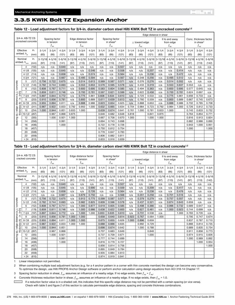
Table 12 - Load adjustment factors for 3/4-in. diameter carbon steel Hilti KWIK Bolt TZ in uncracked concrete1,2
3/4-in. KB-TZ CS uncracked concrete
Spacing factor in tension
ƒAN
Edge distance factor in tension
ƒRN
Spacing factor in shear3
ƒAV
Edge distance in shearConc. thickness factor
in shear4
ƒHV
⊥toward edgeƒRV
II to and away from edge
ƒRV
Effective embed. hef
in. 3-1/4 3-3/4 4-3/4 3-1/4 3-3/4 4-3/4 3-1/4 3-3/4 4-3/4 3-1/4 3-3/4 4-3/4 3-1/4 3-3/4 4-3/4 3-1/4 3-3/4 4-3/4(mm) (83) (95) (121) (83) (95) (121) (83) (95) (121) (83) (95) (121) (83) (95) (121) (83) (95) (121)
Nominal embed. hnom
in. 3-13/16 4-5/16 5-9/16 3-13/16 4-5/16 5-9/16 3-13/16 4-5/16 5-9/16 3-13/16 4-5/16 5-9/16 3-13/16 4-5/16 5-9/16 3-13/16 4-5/16 5-9/16(mm) (97) (110) (141) (97) (110) (141) (97) (110) (141) (97) (110) (141) (97) (110) (141) (97) (110) (142)
Spac
ing
(s) /
edg
e di
stan
ce (c
a) / c
oncr
ete
thic
knes
s (h
) - in
. (m
m)
4 (102) n/a n/a 0.640 n/a n/a n/a n/a n/a 0.557 n/a n/a n/a n/a n/a n/a n/a n/a n/a4-1/8 (105) n/a n/a 0.645 n/a n/a 0.546 n/a n/a 0.558 n/a n/a 0.207 n/a n/a 0.414 n/a n/a n/a4-1/2 (114) n/a n/a 0.658 n/a n/a 0.574 n/a n/a 0.564 n/a n/a 0.236 n/a n/a 0.472 n/a n/a n/a4-3/4 (121) n/a n/a 0.667 n/a 0.495 0.594 n/a n/a 0.567 n/a 0.348 0.256 n/a 0.495 0.512 n/a n/a n/a
5 (127) 0.756 0.722 0.675 n/a 0.514 0.613 0.569 0.587 0.571 n/a 0.376 0.276 n/a 0.514 0.552 n/a n/a n/a5-1/2 (140) 0.782 0.744 0.693 n/a 0.553 0.653 0.576 0.595 0.578 n/a 0.433 0.319 n/a 0.553 0.637 0.553 n/a n/a
6 (152) 0.808 0.767 0.711 n/a 0.600 0.695 0.583 0.604 0.585 n/a 0.494 0.363 n/a 0.600 0.695 0.577 0.645 n/a7 (178) 0.859 0.811 0.746 n/a 0.700 0.781 0.597 0.621 0.599 n/a 0.622 0.458 n/a 0.700 0.781 0.624 0.697 n/a
7-3/4 (197) 0.897 0.844 0.772 n/a 0.775 0.861 0.608 0.634 0.610 n/a 0.725 0.533 n/a 0.775 0.861 0.656 0.733 n/a8 (203) 0.910 0.856 0.781 n/a 0.800 0.889 0.611 0.639 0.613 n/a 0.760 0.559 n/a 0.800 0.889 0.667 0.745 0.673
8-7/8 (225) 0.955 0.894 0.811 n/a 0.888 0.986 0.623 0.654 0.625 n/a 0.888 0.653 n/a 0.888 0.986 0.702 0.785 0.7089-1/2 (241) 0.987 0.922 0.833 0.792 0.950 1.000 0.632 0.665 0.634 0.704 0.984 0.723 0.792 0.984 1.000 0.726 0.812 0.733
10 (254) 1.000 0.944 0.851 0.833 1.000 0.639 0.674 0.641 0.761 1.000 0.781 0.833 1.000 0.745 0.833 0.75210-1/2 (267) 0.967 0.868 0.875 0.646 0.682 0.648 0.818 0.841 0.875 0.764 0.854 0.771
12 (305) 1.000 0.921 1.000 0.667 0.708 0.670 1.000 1.000 1.000 0.816 0.913 0.82414 (356) 0.991 0.694 0.743 0.698 0.882 0.986 0.89016 (406) 1.000 0.722 0.778 0.726 0.943 1.000 0.95118 (457) 0.750 0.812 0.754 1.000 1.00020 (508) 0.778 0.847 0.78322 (559) 0.806 0.882 0.811
> 24 (610) 0.833 0.916 0.839
Table 13 - Load adjustment factors for 3/4-in. diameter carbon steel Hilti KWIK Bolt TZ in cracked concrete1,2
3/4-in. KB-TZ CS cracked concrete
Spacing factor in tension
ƒAN
Edge distance factor in tension
ƒRN
Spacing factor in shear3
ƒAV
Edge distance in shearConc. thickness factor
in shear4
ƒHV
⊥toward edgeƒRV
II to and away from edge
ƒRV
Effective embed. hef
in. 3-1/4 3-3/4 4-3/4 3-1/4 3-3/4 4-3/4 3-1/4 3-3/4 4-3/4 3-1/4 3-3/4 4-3/4 3-1/4 3-3/4 4-3/4 3-1/4 3-3/4 4-3/4(mm) (83) (95) (121) (83) (95) (121) (83) (95) (121) (83) (95) (121) (83) (95) (121) (83) (95) (121)
Nominal embed. hnom
in. 3-13/16 4-5/16 5-9/16 3-13/16 4-5/16 5-9/16 3-13/16 4-5/16 5-9/16 3-13/16 4-5/16 5-9/16 3-13/16 4-5/16 5-9/16 3-13/16 4-5/16 5-9/16(mm) (97) (110) (141) (97) (110) (141) (97) (110) (141) (97) (110) (141) (97) (110) (141) (97) (110) (142)
Spac
ing
(s) /
edg
e di
stan
ce (c
a) / c
oncr
ete
thic
knes
s (h
) - in
. (m
m)
4 (102) n/a n/a 0.640 n/a n/a n/a n/a n/a 0.557 n/a n/a n/a n/a n/a n/a n/a n/a n/a4-1/8 (105) n/a n/a 0.645 n/a n/a 0.690 n/a n/a 0.559 n/a n/a 0.209 n/a n/a 0.417 n/a n/a n/a4-1/2 (114) n/a n/a 0.658 n/a n/a 0.726 n/a n/a 0.564 n/a n/a 0.238 n/a n/a 0.476 n/a n/a n/a4-3/4 (121) n/a n/a 0.667 n/a 0.879 0.750 n/a n/a 0.568 n/a 0.351 0.258 n/a 0.701 0.516 n/a n/a n/a
5 (127) 0.756 0.722 0.675 n/a 0.913 0.775 0.599 0.587 0.571 n/a 0.379 0.279 n/a 0.757 0.557 n/a n/a n/a5-1/2 (140) 0.782 0.744 0.693 n/a 0.982 0.825 0.609 0.596 0.578 n/a 0.437 0.321 n/a 0.874 0.643 0.659 n/a n/a
6 (152) 0.808 0.767 0.711 n/a 1.000 0.877 0.619 0.605 0.585 n/a 0.498 0.366 n/a 0.996 0.732 0.689 0.647 n/a7 (178) 0.859 0.811 0.746 n/a 1.000 0.986 0.638 0.622 0.600 n/a 0.627 0.461 n/a 1.000 0.923 0.744 0.699 n/a
7-3/4 (197) 0.897 0.844 0.772 n/a 1.000 1.000 0.653 0.635 0.610 n/a 0.731 0.538 n/a 1.000 0.783 0.735 n/a8 (203) 0.910 0.856 0.781 1.000 1.000 0.658 0.640 0.614 0.923 0.767 0.564 1.000 0.795 0.747 0.674
8-7/8 (225) 0.955 0.894 0.811 1.000 1.000 0.675 0.655 0.626 1.000 0.896 0.659 0.837 0.787 0.7109-1/2 (241) 0.987 0.922 0.833 1.000 1.000 0.688 0.666 0.635 0.992 0.729 0.866 0.814 0.735
10 (254) 1.000 0.944 0.851 0.698 0.674 0.642 1.000 0.788 0.889 0.835 0.75410-1/2 (267) 0.967 0.868 0.707 0.683 0.649 0.848 0.911 0.856 0.773
12 (305) 1.000 0.921 0.737 0.709 0.671 1.000 0.974 0.915 0.82614 (356) 0.991 0.777 0.744 0.699 1.000 0.989 0.89216 (406) 1.000 0.816 0.779 0.727 1.000 0.95418 (457) 0.856 0.814 0.756 1.00020 (508) 0.895 0.849 0.78422 (559) 0.935 0.884 0.813
> 24 (610) 0.974 0.919 0.841
1 Linear interpolation not permitted.2 When combining multiple load adjustment factors (e.g. for a 4 anchor pattern in a corner with thin concrete member) the design can become very conservative.
To optimize the design, use Hilti PROFIS Anchor Design software or perform anchor calculation using design equations from ACI 318-14 Chapter 17.3 Spacing factor reduction in shear, ƒAV,assumesaninfluenceofanearbyedge.Ifnoedgeexists,thenƒAV = ƒAN.4 Concrete thickness reduction factor in shear, ƒHV,assumesaninfluenceofanearbyedge.Ifnoedgeexists,thenƒHV = 1.0.
Ifareductionfactorvalueisinashadedcell,thisindicatesthatthisspecificedgedistancemaynotbepermittedwithacertainspacing(orviceversa). Checkwithtable5andfigure2ofthissectiontocalculatepermissableedgedistance,spacingandconcretethicknesscombinations.
Mechanical Anchoring Systems
KWIK Bolt TZ Expansion Anchor 3.3.5
3.3.9
3.3.9
3.3.9
3.3.9
3.3.1
3.3.2
3.3.3
3.3.9
3.3.5
3.3.6
3.3.7
3.3.8
3.3.9
3.3.9
3.3.4
Hilti, Inc. (US) 1-800-879-8000 | www.us.hilti.com I en español 1-800-879-5000 I Hilti (Canada) Corp. 1-800-363-4458 I www.hilti.ca I Anchor Fastening Technical Guide 2016 277
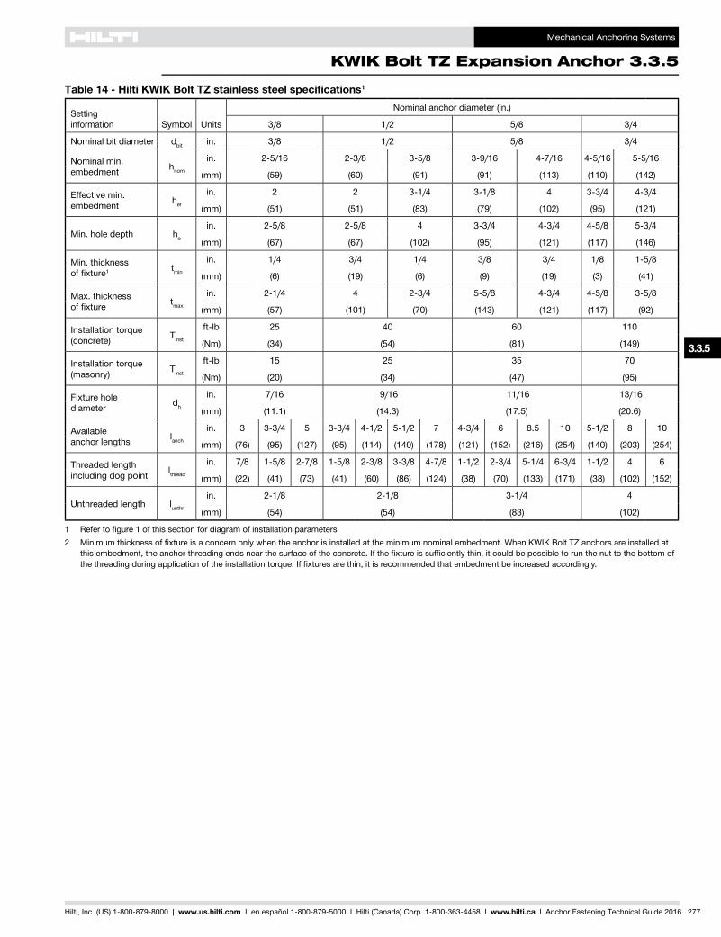
Table 14 - Hilti KWIK Bolt TZ stainless steel specifications1
Setting information Symbol Units
Nominal anchor diameter (in.)
3/8 1/2 5/8 3/4
Nominal bit diameter dbit in. 3/8 1/2 5/8 3/4
Nominal min. embedment hnom
in. 2-5/16 2-3/8 3-5/8 3-9/16 4-7/16 4-5/16 5-5/16
(mm) (59) (60) (91) (91) (113) (110) (142)
Effective min. embedment hef
in. 2 2 3-1/4 3-1/8 4 3-3/4 4-3/4
(mm) (51) (51) (83) (79) (102) (95) (121)
Min. hole depth ho
in. 2-5/8 2-5/8 4 3-3/4 4-3/4 4-5/8 5-3/4
(mm) (67) (67) (102) (95) (121) (117) (146)
Min. thickness of fixture1 tmin
in. 1/4 3/4 1/4 3/8 3/4 1/8 1-5/8
(mm) (6) (19) (6) (9) (19) (3) (41)
Max. thickness of fixture tmax
in. 2-1/4 4 2-3/4 5-5/8 4-3/4 4-5/8 3-5/8
(mm) (57) (101) (70) (143) (121) (117) (92)
Installation torque (concrete) Tinst
ft-lb 25 40 60 110
(Nm) (34) (54) (81) (149)
Installation torque (masonry) Tinst
ft-lb 15 25 35 70
(Nm) (20) (34) (47) (95)
Fixture hole diameter dh
in. 7/16 9/16 11/16 13/16
(mm) (11.1) (14.3) (17.5) (20.6)
Available anchor lengths lanch
in. 3 3-3/4 5 3-3/4 4-1/2 5-1/2 7 4-3/4 6 8.5 10 5-1/2 8 10
(mm) (76) (95) (127) (95) (114) (140) (178) (121) (152) (216) (254) (140) (203) (254)
Threaded length including dog point lthread
in. 7/8 1-5/8 2-7/8 1-5/8 2-3/8 3-3/8 4-7/8 1-1/2 2-3/4 5-1/4 6-3/4 1-1/2 4 6
(mm) (22) (41) (73) (41) (60) (86) (124) (38) (70) (133) (171) (38) (102) (152)
Unthreaded length lunthr
in. 2-1/8 2-1/8 3-1/4 4
(mm) (54) (54) (83) (102)
1 Refertofigure1ofthissectionfordiagramofinstallationparameters2 Minimumthicknessoffixtureisaconcernonlywhentheanchorisinstalledattheminimumnominalembedment.WhenKWIKBoltTZanchorsareinstalledat
thisembedment,theanchorthreadingendsnearthesurfaceoftheconcrete.Ifthefixtureissufficientlythin,itcouldbepossibletorunthenuttothebottomofthethreadingduringapplicationoftheinstallationtorque.Iffixturesarethin,itisrecommendedthatembedmentbeincreasedaccordingly.
Mechanical Anchoring Systems
3.3.5 KWIK Bolt TZ Expansion Anchor
278 Hilti, Inc. (US) 1-800-879-8000 | www.us.hilti.com I en español 1-800-879-5000 I Hilti (Canada) Corp. 1-800-363-4458 I www.hilti.ca I Anchor Fastening Technical Guide 2016
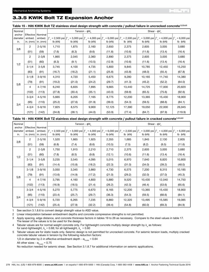
Table 15 - Hilti KWIK Bolt TZ stainless steel design strength with concrete / pullout failure in uncracked concrete1,2,3,4,5
Nominal anchor
diameter in.
Effective embed. in. (mm)
Nominal embed. in. (mm)
Tension - фNn Shear - фVn
ƒ'c = 2,500 psi lb (kN)
ƒ'c = 3,000 psi lb (kN)
ƒ'c = 4,000 psi lb (kN)
ƒ'c = 6,000 psi lb (kN)
ƒ'c = 2,500 psi lb (kN)
ƒ'c = 3,000 psi lb (kN)
ƒ'c = 4,000 psi lb (kN)
ƒ'c = 6,000 psi lb (kN)
3/82 2-5/16 1,710 1,875 2,160 2,650 2,375 2,605 3,005 3,680
(51) (59) (7.6) (8.3) (9.6) (11.8) (10.6) (11.6) (13.4) (16.4)
1/2
2 2-3/8 1,865 2,045 2,360 2,890 2,375 2,605 3,005 3,680
(51) (60) (8.3) (9.1) (10.5) (12.9) (10.6) (11.6) (13.4) (16.4)
3-1/4 3-5/8 3,745 4,100 4,735 5,800 9,845 10,785 12,450 15,250
(83) (91) (16.7) (18.2) (21.1) (25.8) (43.8) (48.0) (55.4) (67.8)
5/8
3-1/8 3-9/16 4,310 4,720 5,450 6,675 9,280 10,165 11,740 14,380
(79) (91) (19.2) (21.0) (24.2) (29.7) (41.3) (45.2) (52.2) (64.0)
4 4-7/16 6,240 6,835 7,895 9,665 13,440 14,725 17,000 20,820
(102) (113) (27.8) (30.4) (35.1) (43.0) (59.8) (65.5) (75.6) (92.6)
3/4
3-3/4 4-5/16 5,665 6,205 7,165 8,775 12,200 13,365 15,430 18,900
(95) (110) (25.2) (27.6) (31.9) (39.0) (54.3) (59.5) (68.6) (84.1)
4-3/4 5-9/16 7,825 8,575 9,900 12,125 17,390 19,050 22,000 26,945
(121) (142) (34.8) (38.1) (44.0) (53.9) (77.4) (84.7) (97.9) (119.9)
Table 16 - Hilti KWIK Bolt TZ stainless steel design strength with concrete / pullout failure in cracked concrete1,2,3,4,5
Nominal anchor
diameter in.
Effective embed. in. (mm)
Nominal embed. in. (mm)
Tension - фNn Shear - фVn
ƒ'c = 2,500 psi lb (kN)
ƒ'c = 3,000 psi lb (kN)
ƒ'c = 4,000 psi lb (kN)
ƒ'c = 6,000 psi lb (kN)
ƒ'c = 2,500 psi lb (kN)
ƒ'c = 3,000 psi lb (kN)
ƒ'c = 4,000 psi lb (kN)
ƒ'c = 6,000 psi lb (kN)
3/82 2-5/16 1,520 1,665 1,925 2,355 1,685 1,845 2,130 2,605
(51) (59) (6.8) (7.4) (8.6) (10.5) (7.5) (8.2) (9.5) (11.6)
1/2
2 2-3/8 1,750 1,915 2,210 2,710 2,375 2,605 3,005 3,680
(51) (60) (7.8) (8.5) (9.8) (12.1) (10.6) (11.6) (13.4) (16.4)
3-1/4 3-5/8 3,235 3,545 4,095 5,015 6,970 7,640 8,820 10,800
(83) (91) (14.4) (15.8) (18.2) (22.3) (31.0) (34.0) (39.2) (48.0)
5/8
3-1/8 3-9/16 3,050 3,345 3,860 4,730 6,575 7,200 8,315 10,185
(79) (91) (13.6) (14.9) (17.2) (21.0) (29.2) (32.0) (37.0) (45.3)
4 4-7/16 3,795 4,160 4,800 5,880 9,520 10,430 12,040 14,750
(102) (113) (16.9) (18.5) (21.4) (26.2) (42.3) (46.4) (53.6) (65.6)
3/4
3-3/4 4-5/16 5,270 5,775 6,670 8,165 12,200 13,365 15,430 18,900
(95) (110) (23.4) (25.7) (29.7) (36.3) (54.3) (59.5) (68.6) (84.1)
4-3/4 5-9/16 5,720 6,265 7,235 8,860 12,320 13,495 15,585 19,085
(121) (142) (25.4) (27.9) (32.2) (39.4) (54.8) (60.0) (69.3) (84.9)
1 See section 3.1.8.6 to convert design strength value to ASD value.2 Linear interpolation between embedment depths and concrete compressive strengths is not permitted.3 Apply spacing, edge distance, and concrete thickness factors in tables 19 to 26 as necessary. Compare to the steel values in table 17.
The lesser of the values is to be used for the design.4 Tabularvaluesarefornormalweightconcreteonly.Forlightweightconcretemultiplydesignstrengthbyλa as follows:
forsand-lightweight,λa=0.68;forall-lightweight,λa = 0.605 Tabular values are for static loads only. Seismic design is not permitted for uncracked concrete. For seismic tension loads, multiply cracked
concrete tabular values in tension by the following reduction factors: 1/2-indiameterby2-ineffectiveembedmentdepth-αN,seis = 0.64 Allothersizes-αN,seis = 0.75 No reduction needed for seismic shear. See Section 3.1.8.7 for additional information on seismic applications.
Mechanical Anchoring Systems
KWIK Bolt TZ Expansion Anchor 3.3.5
3.3.9
3.3.9
3.3.9
3.3.9
3.3.1
3.3.2
3.3.3
3.3.9
3.3.5
3.3.6
3.3.7
3.3.8
3.3.9
3.3.9
3.3.4
Hilti, Inc. (US) 1-800-879-8000 | www.us.hilti.com I en español 1-800-879-5000 I Hilti (Canada) Corp. 1-800-363-4458 I www.hilti.ca I Anchor Fastening Technical Guide 2016 279
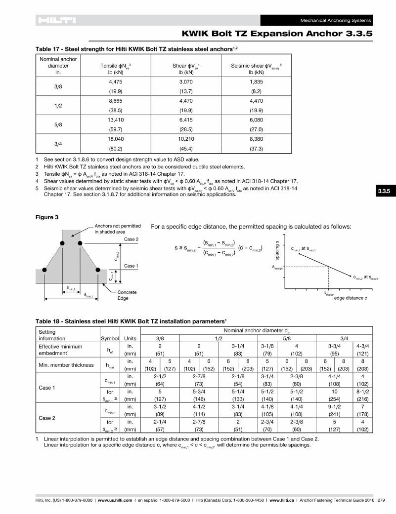
Table 18 - Stainless steel Hilti KWIK Bolt TZ installation parameters1
Settinginformation Symbol Units
Nominal anchor diameter do
3/8 1/2 5/8 3/4Effective minimum embedment1 hef
in. 2 2 3-1/4 3-1/8 4 3-3/4 4-3/4(mm) (51) (51) (83) (79) (102) (95) (121)
Min. member thickness hmin
in. 4 5 4 6 6 8 5 6 8 6 8 8(mm) (102) (127) (102) (152) (152) (203) (127) (152) (203) (152) (203) (203)
Case 1cmin,1
in. 2-1/2 2-7/8 2-1/8 3-1/4 2-3/8 4-1/4 4(mm) (64) (73) (54) (83) (60) (108) (102)
for smin,1≥
in. 5 5-3/4 5-1/4 5-1/2 5-1/2 10 8-1/2(mm) (127) (146) (133) (140) (140) (254) (216)
Case 2cmin,2
in. 3-1/2 4-1/2 3-1/4 4-1/8 4-1/4 9-1/2 7(mm) (89) (114) (83) (105) (108) (241) (178)
for smin,2≥
in. 2-1/4 2-7/8 2 2-3/4 2-3/8 5 4(mm) (57) (73) (51) (70) (60) (127) (102)
1 Linear interpolation is permitted to establish an edge distance and spacing combination between Case 1 and Case 2. Linearinterpolationforaspecificedgedistancec,wherecmin,1 < c < cmin,2, will determine the permissible spacings.
Table 17 - Steel strength for Hilti KWIK Bolt TZ stainless steel anchors1,2
Nominal anchor diameter
in.Tensile фNsa
3
lb (kN)Shear фVsa
4
lb (kN)Seismic shear фVsa,eq
5
lb (kN)
3/84,475 3,070 1,835
(19.9) (13.7) (8.2)
1/28,665 4,470 4,470
(38.5) (19.9) (19.9)
5/813,410 6,415 6,080
(59.7) (28.5) (27.0)
3/418,040 10,210 8,380
(80.2) (45.4) (37.3)
1 See section 3.1.8.6 to convert design strength value to ASD value.2 Hilti KWIK Bolt TZ stainless steel anchors are to be considered ductile steel elements.3 TensileфNsa=фAse,N futa as noted in ACI 318-14 Chapter 17.4 ShearvaluesdeterminedbystaticsheartestswithфVsa<ф0.60Ase,V futa as noted in ACI 318-14 Chapter 17.5 SeismicshearvaluesdeterminedbyseismicsheartestswithфVsa,eq<ф0.60Ase,V futa as noted in ACI 318-14
Chapter 17. See section 3.1.8.7 for additional information on seismic applications.
Figure 3For a specific edge distance, the permitted spacing is calculated as follows:
(smin,1 – smin,2) s≥smin,2 + ___________ (c – cmin,2) (cmin,1 – cmin,2)
Concrete Edge
Anchors not permitted in shaded area
smin,2
smin,1
c min
,1c m
in,2
Case 1
Case 2
cdesignedge distance c
cmin,1 at smin,1
cmin,2 at smin,2
sdesign
spac
ing
s
Mechanical Anchoring Systems
3.3.5 KWIK Bolt TZ Expansion Anchor
280 Hilti, Inc. (US) 1-800-879-8000 | www.us.hilti.com I en español 1-800-879-5000 I Hilti (Canada) Corp. 1-800-363-4458 I www.hilti.ca I Anchor Fastening Technical Guide 2016
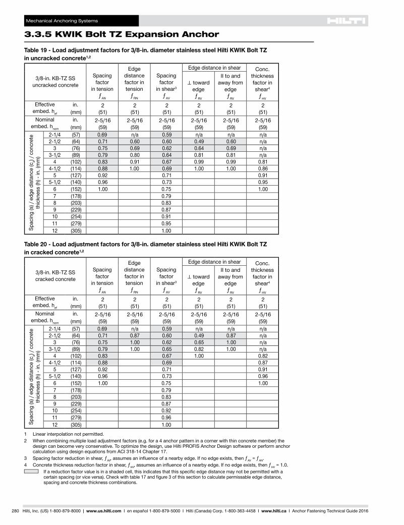
Table 19 - Load adjustment factors for 3/8-in. diameter stainless steel Hilti KWIK Bolt TZ in uncracked concrete1,2
3/8-in. KB-TZ SS uncracked concrete
Spacing factor
in tensionƒAN
Edge distance factor in tension
ƒRN
Spacing factor
in shear3
ƒAV
Edge distance in shear Conc. thickness factor in shear4
ƒHV
⊥toward edgeƒRV
II to and away from
edgeƒRV
Effective embed. hef
in. 2 2 2 2 2 2(mm) (51) (51) (51) (51) (51) (51)
Nominal embed. hnom
in. 2-5/16 2-5/16 2-5/16 2-5/16 2-5/16 2-5/16(mm) (59) (59) (59) (59) (59) (59)
Spac
ing
(s) /
edg
e di
stan
ce (c
a) / c
oncr
ete
thic
knes
s (h
) - in
. (m
m)
2-1/4 (57) 0.69 n/a 0.59 n/a n/a n/a2-1/2 (64) 0.71 0.60 0.60 0.49 0.60 n/a
3 (76) 0.75 0.69 0.62 0.64 0.69 n/a3-1/2 (89) 0.79 0.80 0.64 0.81 0.81 n/a
4 (102) 0.83 0.91 0.67 0.99 0.99 0.814-1/2 (114) 0.88 1.00 0.69 1.00 1.00 0.86
5 (127) 0.92 0.71 0.915-1/2 (140) 0.96 0.73 0.95
6 (152) 1.00 0.75 1.007 (178) 0.798 (203) 0.839 (229) 0.87
10 (254) 0.9111 (279) 0.9512 (305) 1.00
Table 20 - Load adjustment factors for 3/8-in. diameter stainless steel Hilti KWIK Bolt TZ in cracked concrete1,2
3/8-in. KB-TZ SS cracked concrete
Spacing factor
in tensionƒAN
Edge distance factor in tension
ƒRN
Spacing factor
in shear3
ƒAV
Edge distance in shear Conc. thickness factor in shear4
ƒHV
⊥toward edgeƒRV
II to and away from
edgeƒRV
Effective embed. hef
in. 2 2 2 2 2 2(mm) (51) (51) (51) (51) (51) (51)
Nominal embed. hnom
in. 2-5/16 2-5/16 2-5/16 2-5/16 2-5/16 2-5/16(mm) (59) (59) (59) (59) (59) (59)
Spac
ing
(s) /
edg
e di
stan
ce (c
a) / c
oncr
ete
thic
knes
s (h
) - in
. (m
m)
2-1/4 (57) 0.69 n/a 0.59 n/a n/a n/a2-1/2 (64) 0.71 0.87 0.60 0.49 0.87 n/a
3 (76) 0.75 1.00 0.62 0.65 1.00 n/a3-1/2 (89) 0.79 1.00 0.65 0.82 1.00 n/a
4 (102) 0.83 0.67 1.00 0.824-1/2 (114) 0.88 0.69 0.87
5 (127) 0.92 0.71 0.915-1/2 (140) 0.96 0.73 0.96
6 (152) 1.00 0.75 1.007 (178) 0.798 (203) 0.839 (229) 0.87
10 (254) 0.9211 (279) 0.9612 (305) 1.00
1 Linear interpolation not permitted.2 When combining multiple load adjustment factors (e.g. for a 4 anchor pattern in a corner with thin concrete member) the
design can become very conservative. To optimize the design, use Hilti PROFIS Anchor Design software or perform anchor calculation using design equations from ACI 318-14 Chapter 17.
3 Spacing factor reduction in shear, ƒAV,assumesaninfluenceofanearbyedge.Ifnoedgeexists,thenƒAV = ƒAN.4 Concrete thickness reduction factor in shear, ƒHV,assumesaninfluenceofanearbyedge.Ifnoedgeexists,thenƒHV = 1.0.
Ifareductionfactorvalueisinashadedcell,thisindicatesthatthisspecificedgedistancemaynotbepermittedwithacertainspacing(orviceversa).Checkwithtable17andfigure3ofthissectiontocalculatepermissableedgedistance,spacing and concrete thickness combinations.
Mechanical Anchoring Systems
KWIK Bolt TZ Expansion Anchor 3.3.5
3.3.9
3.3.9
3.3.9
3.3.9
3.3.1
3.3.2
3.3.3
3.3.9
3.3.5
3.3.6
3.3.7
3.3.8
3.3.9
3.3.9
3.3.4
Hilti, Inc. (US) 1-800-879-8000 | www.us.hilti.com I en español 1-800-879-5000 I Hilti (Canada) Corp. 1-800-363-4458 I www.hilti.ca I Anchor Fastening Technical Guide 2016 281
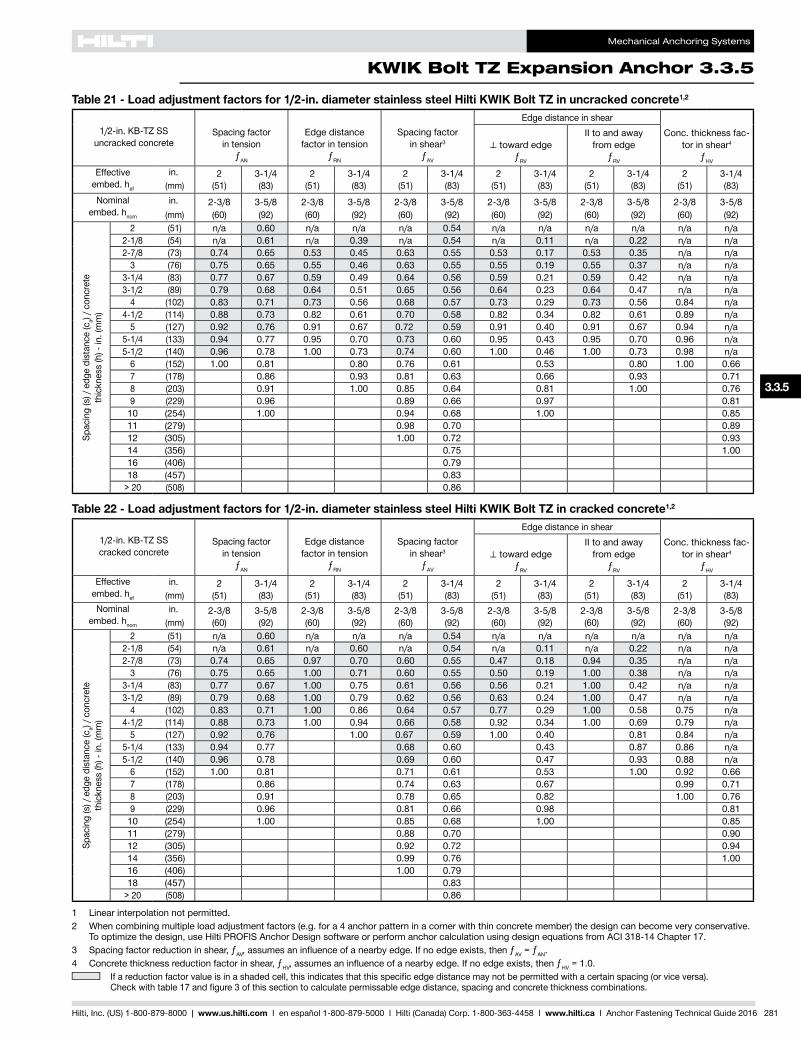
Table 21 - Load adjustment factors for 1/2-in. diameter stainless steel Hilti KWIK Bolt TZ in uncracked concrete1,2
1/2-in. KB-TZ SS uncracked concrete
Spacing factor in tension
ƒAN
Edge distance factor in tension
ƒRN
Spacing factor in shear3
ƒAV
Edge distance in shearConc. thickness fac-
tor in shear4
ƒHV
⊥toward edgeƒRV
II to and away from edge
ƒRV
Effective embed. hef
in. 2 3-1/4 2 3-1/4 2 3-1/4 2 3-1/4 2 3-1/4 2 3-1/4(mm) (51) (83) (51) (83) (51) (83) (51) (83) (51) (83) (51) (83)
Nominal embed. hnom
in. 2-3/8 3-5/8 2-3/8 3-5/8 2-3/8 3-5/8 2-3/8 3-5/8 2-3/8 3-5/8 2-3/8 3-5/8(mm) (60) (92) (60) (92) (60) (92) (60) (92) (60) (92) (60) (92)
Spac
ing
(s) /
edg
e di
stan
ce (c
a) / c
oncr
ete
thic
knes
s (h
) - in
. (m
m)
2 (51) n/a 0.60 n/a n/a n/a 0.54 n/a n/a n/a n/a n/a n/a2-1/8 (54) n/a 0.61 n/a 0.39 n/a 0.54 n/a 0.11 n/a 0.22 n/a n/a2-7/8 (73) 0.74 0.65 0.53 0.45 0.63 0.55 0.53 0.17 0.53 0.35 n/a n/a
3 (76) 0.75 0.65 0.55 0.46 0.63 0.55 0.55 0.19 0.55 0.37 n/a n/a3-1/4 (83) 0.77 0.67 0.59 0.49 0.64 0.56 0.59 0.21 0.59 0.42 n/a n/a3-1/2 (89) 0.79 0.68 0.64 0.51 0.65 0.56 0.64 0.23 0.64 0.47 n/a n/a
4 (102) 0.83 0.71 0.73 0.56 0.68 0.57 0.73 0.29 0.73 0.56 0.84 n/a4-1/2 (114) 0.88 0.73 0.82 0.61 0.70 0.58 0.82 0.34 0.82 0.61 0.89 n/a
5 (127) 0.92 0.76 0.91 0.67 0.72 0.59 0.91 0.40 0.91 0.67 0.94 n/a5-1/4 (133) 0.94 0.77 0.95 0.70 0.73 0.60 0.95 0.43 0.95 0.70 0.96 n/a5-1/2 (140) 0.96 0.78 1.00 0.73 0.74 0.60 1.00 0.46 1.00 0.73 0.98 n/a
6 (152) 1.00 0.81 0.80 0.76 0.61 0.53 0.80 1.00 0.667 (178) 0.86 0.93 0.81 0.63 0.66 0.93 0.718 (203) 0.91 1.00 0.85 0.64 0.81 1.00 0.769 (229) 0.96 0.89 0.66 0.97 0.81
10 (254) 1.00 0.94 0.68 1.00 0.8511 (279) 0.98 0.70 0.8912 (305) 1.00 0.72 0.9314 (356) 0.75 1.0016 (406) 0.7918 (457) 0.83
> 20 (508) 0.86
Table 22 - Load adjustment factors for 1/2-in. diameter stainless steel Hilti KWIK Bolt TZ in cracked concrete1,2
1/2-in. KB-TZ SS cracked concrete
Spacing factor in tension
ƒAN
Edge distance factor in tension
ƒRN
Spacing factor in shear3
ƒAV
Edge distance in shearConc. thickness fac-
tor in shear4
ƒHV
⊥toward edgeƒRV
II to and away from edge
ƒRV
Effective embed. hef
in. 2 3-1/4 2 3-1/4 2 3-1/4 2 3-1/4 2 3-1/4 2 3-1/4(mm) (51) (83) (51) (83) (51) (83) (51) (83) (51) (83) (51) (83)
Nominal embed. hnom
in. 2-3/8 3-5/8 2-3/8 3-5/8 2-3/8 3-5/8 2-3/8 3-5/8 2-3/8 3-5/8 2-3/8 3-5/8(mm) (60) (92) (60) (92) (60) (92) (60) (92) (60) (92) (60) (92)
Spac
ing
(s) /
edg
e di
stan
ce (c
a) / c
oncr
ete
thic
knes
s (h
) - in
. (m
m)
2 (51) n/a 0.60 n/a n/a n/a 0.54 n/a n/a n/a n/a n/a n/a2-1/8 (54) n/a 0.61 n/a 0.60 n/a 0.54 n/a 0.11 n/a 0.22 n/a n/a2-7/8 (73) 0.74 0.65 0.97 0.70 0.60 0.55 0.47 0.18 0.94 0.35 n/a n/a
3 (76) 0.75 0.65 1.00 0.71 0.60 0.55 0.50 0.19 1.00 0.38 n/a n/a3-1/4 (83) 0.77 0.67 1.00 0.75 0.61 0.56 0.56 0.21 1.00 0.42 n/a n/a3-1/2 (89) 0.79 0.68 1.00 0.79 0.62 0.56 0.63 0.24 1.00 0.47 n/a n/a
4 (102) 0.83 0.71 1.00 0.86 0.64 0.57 0.77 0.29 1.00 0.58 0.75 n/a4-1/2 (114) 0.88 0.73 1.00 0.94 0.66 0.58 0.92 0.34 1.00 0.69 0.79 n/a
5 (127) 0.92 0.76 1.00 0.67 0.59 1.00 0.40 0.81 0.84 n/a5-1/4 (133) 0.94 0.77 0.68 0.60 0.43 0.87 0.86 n/a5-1/2 (140) 0.96 0.78 0.69 0.60 0.47 0.93 0.88 n/a
6 (152) 1.00 0.81 0.71 0.61 0.53 1.00 0.92 0.667 (178) 0.86 0.74 0.63 0.67 0.99 0.718 (203) 0.91 0.78 0.65 0.82 1.00 0.769 (229) 0.96 0.81 0.66 0.98 0.81
10 (254) 1.00 0.85 0.68 1.00 0.8511 (279) 0.88 0.70 0.9012 (305) 0.92 0.72 0.9414 (356) 0.99 0.76 1.0016 (406) 1.00 0.7918 (457) 0.83
> 20 (508) 0.86
1 Linear interpolation not permitted.2 When combining multiple load adjustment factors (e.g. for a 4 anchor pattern in a corner with thin concrete member) the design can become very conservative.
To optimize the design, use Hilti PROFIS Anchor Design software or perform anchor calculation using design equations from ACI 318-14 Chapter 17.3 Spacing factor reduction in shear, ƒAV,assumesaninfluenceofanearbyedge.Ifnoedgeexists,thenƒAV = ƒAN.4 Concrete thickness reduction factor in shear, ƒHV,assumesaninfluenceofanearbyedge.Ifnoedgeexists,thenƒHV = 1.0.
Ifareductionfactorvalueisinashadedcell,thisindicatesthatthisspecificedgedistancemaynotbepermittedwithacertainspacing(orviceversa). Checkwithtable17andfigure3ofthissectiontocalculatepermissableedgedistance,spacingandconcretethicknesscombinations.
Mechanical Anchoring Systems
3.3.5 KWIK Bolt TZ Expansion Anchor
282 Hilti, Inc. (US) 1-800-879-8000 | www.us.hilti.com I en español 1-800-879-5000 I Hilti (Canada) Corp. 1-800-363-4458 I www.hilti.ca I Anchor Fastening Technical Guide 2016
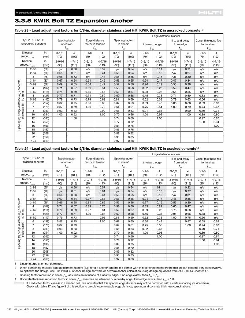
Table 23 - Load adjustment factors for 5/8-in. diameter stainless steel Hilti KWIK Bolt TZ in uncracked concrete1,2
5/8-in. KB-TZ SS uncracked concrete
Spacing factor in tension
ƒAN
Edge distance factor in tension
ƒRN
Spacing factor in shear3
ƒAV
Edge distance in shearConc. thickness fac-
tor in shear4
ƒHV
⊥toward edgeƒRV
II to and away from edge
ƒRV
Effective embed. hef
in. 3-1/8 4 3-1/8 4 3-1/8 4 3-1/8 4 3-1/8 4 3-1/8 4(mm) (79) (102) (79) (102) (79) (102) (79) (102) (79) (102) (79) (102)
Nominal embed. hnom
in. 3-9/16 4-7/16 3-9/16 4-7/16 3-9/16 4-7/16 3-9/16 4-7/16 3-9/16 4-7/16 3-9/16 4-7/16(mm) (90) (113) (90) (113) (90) (113) (90) (113) (90) (113) (90) (113)
Spac
ing
(s) /
edg
e di
stan
ce (c
a) / c
oncr
ete
thic
knes
s (h
) - in
. (m
m)
2-3/8 (60) n/a 0.60 n/a 0.39 n/a 0.54 n/a 0.11 n/a 0.21 n/a n/a2-3/4 (70) 0.65 0.61 n/a 0.41 0.55 0.54 n/a 0.13 n/a 0.27 n/a n/a
3 (76) 0.66 0.63 n/a 0.43 0.56 0.55 n/a 0.15 n/a 0.30 n/a n/a3-1/4 (83) 0.67 0.64 0.51 0.45 0.56 0.55 0.24 0.17 0.47 0.34 n/a n/a3-1/2 (89) 0.69 0.65 0.54 0.47 0.57 0.56 0.26 0.19 0.53 0.38 n/a n/a
4 (102) 0.71 0.67 0.59 0.51 0.58 0.56 0.32 0.23 0.59 0.47 n/a n/a4-1/2 (114) 0.74 0.69 0.65 0.55 0.59 0.57 0.38 0.28 0.65 0.55 n/a n/a
5 (127) 0.77 0.71 0.71 0.59 0.60 0.58 0.45 0.33 0.71 0.59 0.63 n/a5-1/2 (140) 0.79 0.73 0.79 0.63 0.61 0.59 0.52 0.38 0.79 0.63 0.66 n/a
6 (152) 0.82 0.75 0.86 0.68 0.62 0.59 0.59 0.43 0.86 0.68 0.69 0.627 (178) 0.87 0.79 1.00 0.79 0.64 0.61 0.75 0.54 1.00 0.79 0.74 0.678 (203) 0.93 0.83 0.90 0.66 0.63 0.91 0.66 0.90 0.79 0.71
10 (254) 1.00 0.92 1.00 0.70 0.66 1.00 0.92 1.00 0.89 0.8012 (305) 1.00 0.74 0.69 1.00 0.97 0.8714 (356) 0.77 0.72 1.00 0.9416 (406) 0.81 0.75 1.0018 (457) 0.85 0.7820 (508) 0.89 0.8222 (559) 0.93 0.85
> 24 (610) 0.97 0.88
Table 24 - Load adjustment factors for 5/8-in. diameter stainless steel Hilti KWIK Bolt TZ in cracked concrete1,2
5/8-in. KB-TZ SS cracked concrete
Spacing factor in tension
ƒAN
Edge distance factor in tension
ƒRN
Spacing factor in shear3
ƒAV
Edge distance in shearConc. thickness fac-
tor in shear4
ƒHV
⊥toward edgeƒRV
II to and away from edge
ƒRV
Effective embed. hef
in. 3-1/8 4 3-1/8 4 3-1/8 4 3-1/8 4 3-1/8 4 3-1/8 4(mm) (79) (102) (79) (102) (79) (102) (79) (102) (79) (102) (79) (102)
Nominal embed. hnom
in. 3-9/16 4-7/16 3-9/16 4-7/16 3-9/16 4-7/16 3-9/16 4-7/16 3-9/16 4-7/16 3-9/16 4-7/16(mm) (90) (113) (90) (113) (90) (113) (90) (113) (90) (113) (90) (113)
Spac
ing
(s) /
edg
e di
stan
ce (c
a) / c
oncr
ete
thic
knes
s (h
) - in
. (m
m)
2-3/8 (60) n/a 0.60 n/a 0.57 n/a 0.54 n/a 011 n/a 0.22 n/a n/a2-3/4 (70) n/a 0.61 n/a 0.61 n/a 0.54 n/a 0.13 n/a 0.27 n/a n/a
3 (76) 0.66 0.63 n/a 0.64 0.56 0.55 n/a 0.15 n/a 0.31 n/a n/a3-1/4 (83) 0.67 0.64 0.77 0.66 0.56 0.55 0.24 0.17 0.48 0.35 n/a n/a3-1/2 (89) 0.69 0.65 0.81 0.69 0.57 0.56 0.27 0.19 0.53 0.39 n/a n/a
4 (102) 0.71 0.67 0.89 0.75 0.58 0.56 0.33 0.24 0.65 0.47 n/a n/a4-1/2 (114) 0.74 0.69 0.97 0.81 0.59 0.57 0.39 0.28 0.78 0.56 n/a n/a
5 (127) 0.77 0.71 1.00 0.87 0.60 0.58 0.45 0.33 0.91 0.66 0.63 n/a5-1/2 (140) 0.79 0.73 0.93 0.61 0.59 0.52 0.38 1.00 0.76 0.66 n/a
6 (152) 0.82 0.75 1.00 0.62 0.60 0.60 0.43 0.87 0.69 0.627 (178) 0.87 0.79 0.64 0.61 0.75 0.55 1.00 0.74 0.678 (203) 0.93 0.83 0.66 0.63 0.92 0.67 0.79 0.71
10 (254) 1.00 0.92 0.70 0.66 1.00 0.93 0.89 0.8012 (305) 1.00 0.74 0.69 1.00 0.97 0.8714 (356) 0.78 0.72 1.00 0.9416 (406) 0.82 0.75 1.0018 (457) 0.85 0.7920 (508) 0.89 0.8222 (559) 0.93 0.85
> 24 (610) 0.97 0.881 Linear interpolation not permitted.2 When combining multiple load adjustment factors (e.g. for a 4 anchor pattern in a corner with thin concrete member) the design can become very conservative.
To optimize the design, use Hilti PROFIS Anchor Design software or perform anchor calculation using design equations from ACI 318-14 Chapter 17.3 Spacing factor reduction in shear, ƒAV,assumesaninfluenceofanearbyedge.Ifnoedgeexists,thenƒAV = ƒAN.4 Concrete thickness reduction factor in shear, ƒHV,assumesaninfluenceofanearbyedge.Ifnoedgeexists,thenƒHV = 1.0.
Ifareductionfactorvalueisinashadedcell,thisindicatesthatthisspecificedgedistancemaynotbepermittedwithacertainspacing(orviceversa). Checkwithtable17andfigure3ofthissectiontocalculatepermissableedgedistance,spacingandconcretethicknesscombinations.
Mechanical Anchoring Systems
KWIK Bolt TZ Expansion Anchor 3.3.5
3.3.9
3.3.9
3.3.9
3.3.9
3.3.1
3.3.2
3.3.3
3.3.9
3.3.5
3.3.6
3.3.7
3.3.8
3.3.9
3.3.9
3.3.4
Hilti, Inc. (US) 1-800-879-8000 | www.us.hilti.com I en español 1-800-879-5000 I Hilti (Canada) Corp. 1-800-363-4458 I www.hilti.ca I Anchor Fastening Technical Guide 2016 283
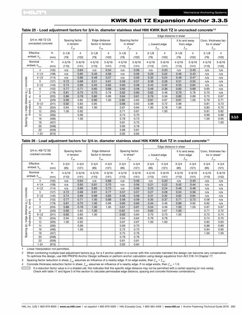
Table 25 - Load adjustment factors for 3/4-in. diameter stainless steel Hilti KWIK Bolt TZ in uncracked concrete1,2
3/4-in. KB-TZ CS uncracked concrete
Spacing factor in tension
ƒAN
Edge distance factor in tension
ƒRN
Spacing factor in shear3
ƒAV
Edge distance in shearConc. thickness fac-
tor in shear4
ƒHV
⊥toward edgeƒRV
II to and away from edge
ƒRV
Effective embed. hef
in. 3-1/8 4 3-1/8 4 3-1/8 4 3-1/8 4 3-1/8 4 3-1/8 4 (mm) (79) (102) (79) (102) (79) (102) (79) (102) (79) (102) (79) (102)
Nominal embed. hnom
in. 4-5/16 5-9/16 4-5/16 5-9/16 4-5/16 5-9/16 4-5/16 5-9/16 4-5/16 5-9/16 4-5/16 5-9/16(mm) (110) (141) (110) (141) (110) (141) (110) (141) (110) (141) (110) (142)
Spac
ing
(s) /
edg
e di
stan
ce (c
a) / c
oncr
ete
thic
knes
s (h
) - in
. (m
m)
4 (102) n/a 0.64 n/a 0.54 n/a 0.56 n/a 0.20 n/a 0.40 n/a n/a4-1/4 (108) n/a 0.65 0.46 0.56 n/a 0.56 0.29 0.22 0.46 0.43 n/a n/a4-1/2 (114) n/a 0.66 0.48 0.57 n/a 0.56 0.32 0.24 0.48 0.47 n/a n/a
5 (127) 0.72 0.68 0.51 0.61 0.59 0.57 0.38 0.28 0.51 0.55 n/a n/a5-1/2 (140) 0.74 0.69 0.55 0.65 0.60 0.58 0.43 0.32 0.55 0.64 n/a n/a
6 (152) 0.77 0.71 0.60 0.69 0.60 0.58 0.49 0.36 0.60 0.69 0.65 n/a7 (178) 0.81 0.75 0.70 0.78 0.62 0.60 0.62 0.46 0.70 0.78 0.70 n/a8 (203) 0.86 0.78 0.80 0.89 0.64 0.61 0.76 0.56 0.80 0.89 0.75 0.679 (229) 0.90 0.82 0.90 1.00 0.66 0.63 0.91 0.67 0.91 1.00 0.79 0.71
9-1/2 (241) 0.92 0.83 0.95 0.66 0.63 0.98 0.72 0.98 0.81 0.7310 (254) 0.94 0.85 1.00 0.67 0.64 1.00 0.78 1.00 0.83 0.7512 (305) 1.00 0.92 0.71 0.67 1.00 0.91 0.8214 (356) 0.99 0.74 0.70 0.99 0.8916 (406) 1.00 0.78 0.73 1.00 0.9518 (457) 0.81 0.75 1.0020 (508) 0.85 0.7822 (559) 0.88 0.81
> 24 (610) 0.92 0.84
Table 26 - Load adjustment factors for 3/4-in. diameter stainless steel Hilti KWIK Bolt TZ in cracked concrete1,2
3/4-in. KB-TZ SS cracked concrete
Spacing factor in tension
ƒAN
Edge distance factor in tension
ƒRN
Spacing factor in shear3
ƒAV
Edge distance in shearConc. thickness fac-
tor in shear4
ƒHV
⊥toward edgeƒRV
II to and away from edge
ƒRV
Effective embed. hef
in. 3-3/4 4-3/4 3-3/4 4-3/4 3-3/4 4-3/4 3-3/4 4-3/4 3-3/4 4-3/4 3-3/4 4-3/4(mm) (95) (121) (95) (121) (95) (121) (95) (121) (95) (121) (95) (121)
Nominal embed. hnom
in. 4-5/16 5-9/16 4-5/16 5-9/16 4-5/16 5-9/16 4-5/16 5-9/16 4-5/16 5-9/16 4-5/16 5-9/16(mm) (110) (141) (110) (141) (110) (141) (110) (141) (110) (141) (110) (142)
Spac
ing
(s) /
edg
e di
stan
ce (c
a) / c
oncr
ete
thic
knes
s (h
) - in
. (m
m)
4 (102) n/a 0.64 n/a 0.68 n/a 0.56 n/a 0.20 n/a 0.40 n/a n/a4-1/4 (108) n/a 0.65 0.81 0.70 n/a 0.56 0.21 0.22 0.42 0.44 n/a n/a4-1/2 (114) n/a 0.66 0.85 0.73 n/a 0.56 0.23 0.24 0.46 0.48 n/a n/a
5 (127) 0.72 0.68 0.91 0.77 0.57 0.57 0.27 0.28 0.54 0.56 n/a n/a5-1/2 (140) 0.74 0.69 0.98 0.83 0.58 0.58 0.31 0.32 0.62 0.64 n/a n/a
6 (152) 0.77 0.71 1.00 0.88 0.58 0.59 0.35 0.37 0.71 0.73 0.58 n/a7 (178) 0.81 0.75 1.00 0.99 0.60 0.60 0.44 0.46 0.89 0.92 0.62 n/a8 (203) 0.86 0.78 1.00 1.00 0.61 0.61 0.54 0.56 1.00 1.00 0.67 0.679 (229) 0.90 0.82 1.00 0.62 0.63 0.65 0.67 1.00 0.71 0.72
9-1/2 (241) 0.92 0.83 1.00 0.63 0.64 0.70 0.73 1.00 0.73 0.7410 (254) 0.94 0.85 0.64 0.64 0.76 0.79 0.74 0.7512 (305) 1.00 0.92 0.67 0.67 1.00 1.00 0.82 0.8314 (356) 0.99 0.69 0.70 0.88 0.8916 (406) 1.00 0.72 0.73 0.94 0.9518 (457) 0.75 0.76 1.00 1.0020 (508) 0.78 0.7822 (559) 0.81 0.81
> 24 (610) 0.83 0.841 Linear interpolation not permitted.2 When combining multiple load adjustment factors (e.g. for a 4 anchor pattern in a corner with thin concrete member) the design can become very conservative.
To optimize the design, use Hilti PROFIS Anchor Design software or perform anchor calculation using design equations from ACI 318-14 Chapter 17.3 Spacing factor reduction in shear, ƒAV,assumesaninfluenceofanearbyedge.Ifnoedgeexists,thenƒAV = ƒAN.4 Concrete thickness reduction factor in shear, ƒHV,assumesaninfluenceofanearbyedge.Ifnoedgeexists,thenƒHV = 1.0.
Ifareductionfactorvalueisinashadedcell,thisindicatesthatthisspecificedgedistancemaynotbepermittedwithacertainspacing(orviceversa). Checkwithtable17andfigure3ofthissectiontocalculatepermissableedgedistance,spacingandconcretethicknesscombinations.
Mechanical Anchoring Systems
3.3.5 KWIK Bolt TZ Expansion Anchor
284 Hilti, Inc. (US) 1-800-879-8000 | www.us.hilti.com I en español 1-800-879-5000 I Hilti (Canada) Corp. 1-800-363-4458 I www.hilti.ca I Anchor Fastening Technical Guide 2016
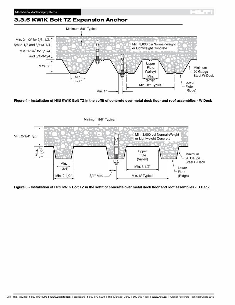
Figure 4 - Installation of Hilti KWIK Bolt TZ in the soffit of concrete over metal deck floor and roof assemblies - W Deck
Figure 5 - Installation of Hilti KWIK Bolt TZ in the soffit of concrete over metal deck floor and roof assemblies - B Deck
Mechanical Anchoring Systems
KWIK Bolt TZ Expansion Anchor 3.3.5
3.3.9
3.3.9
3.3.9
3.3.9
3.3.1
3.3.2
3.3.3
3.3.9
3.3.5
3.3.6
3.3.7
3.3.8
3.3.9
3.3.9
3.3.4
Hilti, Inc. (US) 1-800-879-8000 | www.us.hilti.com I en español 1-800-879-5000 I Hilti (Canada) Corp. 1-800-363-4458 I www.hilti.ca I Anchor Fastening Technical Guide 2016 285
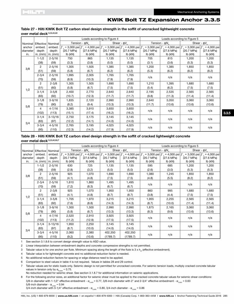
Table 27 - Hilti KWIK Bolt TZ carbon steel design strength in the soffit of uncracked lightweight concrete over metal deck1,2,3,4,5,6
Nominal anchor
diameter in.
Effective embed. depth
in. (mm)
Nominal embed. depth
in. (mm)
Loads according to Figure 4 Loads according to Figure 5Tension - фNn Shear - фVn Tension - фNn Shear - фVn
ƒ'c = 3,000 psi (20.7 MPa)
lb (kN)
ƒ'c = 4,000 psi (27.6 MPa)
lb (kN)
ƒ'c = 3,000 psi (20.7 MPa)
lb (kN)
ƒ'c = 4,000 psi (27.6 MPa)
lb (kN)
ƒ'c = 3,000 psi (20.7 MPa)
lb (kN)
ƒ'c = 4,000 psi (27.6 MPa)
lb (kN)
ƒ'c = 3,000 psi (20.7 MPa)
lb (kN)
ƒ'c = 4,000 psi (27.6 MPa)
lb (kN)
3/8
1-1/2 2-5/16 750 865 1,135 1,135 705 815 1,200 1,200(38) (59) (3.3) (3.8) (5.0) (5.0) (3.1) (3.6) (5.3) (5.3)2 2-5/16 1,305 1,505 1,385 1,385 1,200 1,385 1,850 1,850
(51) (59) (5.8) (6.7) (6.2) (6.2) (5.3) (6.2) (8.2) (8.2)2-3/4 2-5/16 1,995 2,305 1,765 1,765
n/a n/a n/a n/a(70) (59) (8.9) (10.3) (7.9) (7.9)
1/2
2 2-3/8 1,305 1,505 1,690 1,690 1,210 1,395 1,680 1,680(51) (60) (5.8) (6.7) (7.5) (7.5) (5.4) (6.2) (7.5) (7.5)
3-1/4 3-5/8 2,400 2,770 2,640 2,640 2,195 2,535 2,565 2,565(83) (92) (10.7) (12.3) (11.7) (11.7) (9.8) (11.3) (11.4) (11.4)
5/8
3-1/8 3-9/16 1,835 2,120 2,990 2,990 2,640 3,050 3,060 3,060(79) (90) (8.2) (9.4) (13.3) (13.3) (11.7) (13.6) (13.6) (13.6)4 4-7/16 3,385 3,910 3,650 3,650
n/a n/a n/a n/a(102) (113) (15.1) (17.4) (16.2) (16.2)
3/4
3-1/4 3-13/16 2,750 3,175 3,145 3,145n/a n/a n/a n/a
(83) (97) (12.2) (14.1) (14.0) (14.0)3-3/4 4-5/16 2,765 3,195 4,025 4,025
n/a n/a n/a n/a(95) (110) (12.3) (14.2) (17.9) (17.9)
Table 28 - Hilti KWIK Bolt TZ carbon steel design strength in the soffit of cracked lightweight concrete over metal deck1,2,3,4,5,6,7
Nominal anchor
diameter in.
Effective embed. depth
in. (mm)
Nominal embed. depth
in. (mm)
Loads according to Figure 4 Loads according to Figure 5Tension - фNn Shear - фVn Tension - фNn Shear - фVn
ƒ'c = 3,000 psi (20.7 MPa)
lb (kN)
ƒ'c = 4,000 psi (27.6 MPa)
lb (kN)
ƒ'c = 3,000 psi (20.7 MPa)
lb (kN)
ƒ'c = 4,000 psi (27.6 MPa)
lb (kN)
ƒ'c = 3,000 psi (20.7 MPa)
lb (kN)
ƒ'c = 4,000 psi (27.6 MPa)
lb (kN)
ƒ'c = 3,000 psi (20.7 MPa)
lb (kN)
ƒ'c = 4,000 psi (27.6 MPa)
lb (kN)
3/8
1-1/2 2-5/16 630 725 1,135 1,135 595 685 1,200 1,200(38) (59) (2.8) (3.2) (5.0) (5.0) (2.6) (3.0) (5.3) (5.3)2 2-5/16 925 1,070 1,690 1,690 1,080 1,245 1,850 1,850
(51) (59) (4.1) (4.8) (7.5) (7.5) (4.8) (5.5) (8.2) (8.2)2-3/4 2-5/16 1,610 1,860 1,495 1,495
n/a n/a n/a n/a(70) (59) (7.2) (8.3) (6.7) (6.7)
1/2
2 2-3/8 925 1,070 1,950 1,950 860 995 1,680 1,680(51) (60) (4.1) (4.8) (8.7) (8.7) (3.8) (4.4) (7.5) (7.5)
3-1/4 3-5/8 1,705 1,970 3,215 3,215 1,955 2,255 2,565 2,565(83) (92) (7.6) (8.8) (14.3) (14.3) (8.7) (10.0) (11.4) (11.4)
5/8
3-1/8 3-9/16 1,300 1,500 2,990 2,990 1,875 2,165 3,060 3,060(79) (90) (5.8) (6.7) (13.3) (13.3) (8.3) (9.6) (13.6) (13.6)4 4-7/16 2,520 2,910 3,925 3,925
n/a n/a n/a n/a(102) (113) (11.2) (12.9) (17.5) (17.5)
3/4
3-1/4 3-13/16 1,950 2,250 3,145 3,145n/a n/a n/a n/a
(83) (97) (8.7) (10.0) (14.0) (14.0)3-3/4 4-5/16 2,060 2,380 402,350 402,350
n/a n/a n/a n/a(95) (110) (9.2) (10.6) (1789.7) (1789.7)
1 See section 3.1.8.6 to convert design strength value to ASD value.2 Linear interpolation between embedment depths and concrete compressive strengths is not permitted.3 Tabularvalueisforoneanchorperflute.Minimumspacingalongthelengthofthefluteis3xhef (effective embedment).4 Tabular value is for lightweight concrete and no additional reduction factor is needed.5 No additional reduction factors for spacing or edge distance need to be applied.6 Comparison to steel values in table 4 is not required. Values in tables 28 and 29 control.7 Tabular values are for static loads only. Seismic design is not permitted for uncracked concrete. For seismic tension loads, multiply cracked concrete tabular
valuesintensiononlybyαN,seis = 0.75. No reduction needed for seismic shear. See section 3.1.8.7 for additional information on seismic applications.
8 For the following anchor sizes, an additional factor for seismic shear must be applied to the cracked concrete tabular values for seismic shear conditions: 3/8-indiameterwith1-1/2"effectiveembedment-αv,seis =0.77,3/8-inchdiameterwith2"and2-3/4"effectiveembedment-αv,seis = 0.63
5/8-inchdiameter-αv,seis = 0.94 3/4-inchdiameterwith3-1/4"effectiveembedment-αv,seis=0.80,3/4-inchdiameter-αv,seis = 0.86
Mechanical Anchoring Systems
3.3.5 KWIK Bolt TZ Expansion Anchor
286 Hilti, Inc. (US) 1-800-879-8000 | www.us.hilti.com I en español 1-800-879-5000 I Hilti (Canada) Corp. 1-800-363-4458 I www.hilti.ca I Anchor Fastening Technical Guide 2016
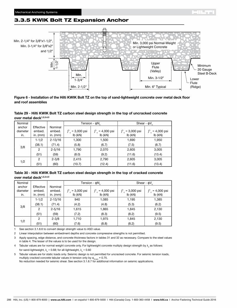
Table 29 - Hilti KWIK Bolt TZ carbon steel design strength in the top of uncracked concrete over metal deck1,2,3,4,5
Nominal anchor
diameter in.
Effective embed. in. (mm)
Nominal embed. in. (mm)
Tension - фNn Shear - фVn
ƒ'c = 3,000 psi lb (kN)
ƒ'c = 4,000 psi lb (kN)
ƒ'c = 3,000 psi lb (kN)
ƒ'c = 4,000 psi lb (kN)
3/8
1-1/2 2-13/16 1,300 1,500 1,690 1,950(38.1) (71.4) (5.8) (6.7) (7.5) (8.7)
2 2-5/16 1,790 2,070 2,605 3,005(51) (59) (8.0) (9.2) (11.6) (13.4)
1/22 2-3/8 2,415 2,790 2,605 3,005
(51) (60) (10.7) (12.4) (11.6) (13.4)
Figure 6 - Installation of the Hilti KWIK Bolt TZ on the top of sand-lightweight concrete over metal deck floor and roof assemblies
Table 30 - Hilti KWIK Bolt TZ carbon steel design strength in the top of cracked concrete over metal deck1,2,3,4,5
Nominal anchor
diameter in.
Effective embed. in. (mm)
Nominal embed. in. (mm)
Tension - фNn Shear - фVn
ƒ'c = 3,000 psi lb (kN)
ƒ'c = 4,000 psi lb (kN)
ƒ'c = 3,000 psi lb (kN)
ƒ'c = 4,000 psi lb (kN)
3/8
1-1/2 2-13/16 940 1,085 1,195 1,385(38.1) (71.4) (4.2) (4.8) (5.3) (6.2)
2 2-5/16 1,615 1,865 1,845 2,130(51) (59) (7.2) (8.3) (8.2) (9.5)
1/22 2-3/8 1,710 1,975 1,845 2,130
(51) (60) (7.6) (8.8) (8.2) (9.5)1 See section 3.1.8.6 to convert design strength value to ASD value.2 Linear interpolation between embedment depths and concrete compressive strengths is not permitted.3 Apply spacing, edge distance, and concrete thickness factors in tables 31 and 32 as necessary. Compare to the steel values
in table 4. The lesser of the values is to be used for the design.4 Tabularvaluesarefornormalweightconcreteonly.Forlightweightconcretemultiplydesignstrengthbyλa as follows: forsand-lightweight,λa=0.68;forall-lightweight,λa = 0.605 Tabular values are for static loads only. Seismic design is not permitted for uncracked concrete. For seismic tension loads,
multiplycrackedconcretetabularvaluesintensiononlybyαN,seis = 0.75. No reduction needed for seismic shear. See section 3.1.8.7 for additional information on seismic applications.
Mechanical Anchoring Systems
KWIK Bolt TZ Expansion Anchor 3.3.5
3.3.9
3.3.9
3.3.9
3.3.9
3.3.1
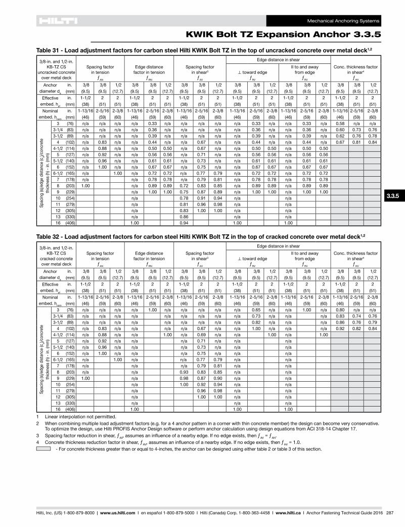
3.3.2
3.3.3
3.3.9
3.3.5
3.3.6
3.3.7
3.3.8
3.3.9
3.3.9
3.3.4
Hilti, Inc. (US) 1-800-879-8000 | www.us.hilti.com I en español 1-800-879-5000 I Hilti (Canada) Corp. 1-800-363-4458 I www.hilti.ca I Anchor Fastening Technical Guide 2016 287
Table 31 - Load adjustment factors for carbon steel Hilti KWIK Bolt TZ in the top of uncracked concrete over metal deck1,2
3/8-in. and 1/2-in.KB-TZ CS
uncracked concreteover metal deck
Spacing factor in tension
ƒAN
Edge distance factor in tension
ƒRN
Spacing factor in shear3
ƒAV
Edge distance in shearConc. thickness factor
in shear4
ƒHV
⊥toward edgeƒRV
II to and away from edge
ƒRV
Anchor diameter da
in. 3/8 3/8 1/2 3/8 3/8 1/2 3/8 3/8 1/2 3/8 3/8 1/2 3/8 3/8 1/2 3/8 3/8 1/2(mm) (9.5) (9.5) (12.7) (9.5) (9.5) (12.7) (9.5) (9.5) (12.7) (9.5) (9.5) (12.7) (9.5) (9.5) (12.7) (9.5) (9.5) (12.7)
Effective embed. hef
in. 1-1/2 2 2 1-1/2 2 2 1-1/2 2 2 1-1/2 2 2 1-1/2 2 2 1-1/2 2 2(mm) (38) (51) (51) (38) (51) (51) (38) (51) (51) (38) (51) (51) (38) (51) (51) (38) (51) (51)
Nominal embed. hnom
in. 1-13/16 2-5/16 2-3/8 1-13/16 2-5/16 2-3/8 1-13/16 2-5/16 2-3/8 1-13/16 2-5/16 2-3/8 1-13/16 2-5/16 2-3/8 1-13/16 2-5/16 2-3/8 (mm) (46) (59) (60) (46) (59) (60) (46) (59) (60) (46) (59) (60) (46) (59) (60) (46) (59) (60)
Spac
ing
(s)/e
dge
dist
ance
(ca)/
conc
rete
thick
ness
(h) -
in. (
mm
)
3 (76) n/a n/a n/a n/a 0.33 n/a n/a n/a n/a n/a 0.33 n/a n/a 0.33 n/a 0.58 n/a n/a3-1/4 (83) n/a n/a n/a n/a 0.36 n/a n/a n/a n/a n/a 0.36 n/a n/a 0.36 n/a 0.60 0.73 0.763-1/2 (89) n/a n/a n/a n/a 0.39 n/a n/a n/a n/a n/a 0.39 n/a n/a 0.39 n/a 0.62 0.76 0.78
4 (102) n/a 0.83 n/a n/a 0.44 n/a n/a 0.67 n/a n/a 0.44 n/a n/a 0.44 n/a 0.67 0.81 0.844-1/2 (114) n/a 0.88 n/a n/a 0.50 0.50 n/a 0.67 n/a n/a 0.50 0.50 n/a 0.50 0.50
5 (127) n/a 0.92 n/a n/a 0.56 0.56 n/a 0.71 n/a n/a 0.56 0.56 n/a 0.56 0.565-1/2 (140) n/a 0.96 n/a n/a 0.61 0.61 n/a 0.73 n/a n/a 0.61 0.61 n/a 0.61 0.61
6 (152) n/a 1.00 n/a n/a 0.67 0.67 n/a 0.75 n/a n/a 0.67 0.67 n/a 0.67 0.676-1/2 (165) n/a 1.00 n/a 0.72 0.72 n/a 0.77 0.79 n/a 0.72 0.72 n/a 0.72 0.72
7 (178) n/a n/a 0.78 0.78 n/a 0.79 0.81 n/a 0.78 0.78 n/a 0.78 0.788 (203) 1.00 n/a 0.89 0.89 0.72 0.83 0.85 n/a 0.89 0.89 n/a 0.89 0.899 (229) n/a 1.00 1.00 0.75 0.87 0.89 n/a 1.00 1.00 n/a 1.00 1.00
10 (254) n/a 0.78 0.91 0.94 n/a n/a11 (279) n/a 0.81 0.96 0.98 n/a n/a12 (305) n/a 0.83 1.00 1.00 n/a n/a13 (330) n/a 0.86 n/a n/a16 (406) 1.00 0.94 1.00 1.00
Table 32 - Load adjustment factors for carbon steel Hilti KWIK Bolt TZ in the top of cracked concrete over metal deck1,2
3/8-in. and 1/2-in.KB-TZ CS
cracked concreteover metal deck
Spacing factor in tension
ƒAN
Edge distance factor in tension
ƒRN
Spacing factor in shear3
ƒAV
Edge distance in shearConc. thickness factor
in shear4
ƒHV
⊥toward edgeƒRV
II to and away from edge
ƒRV
Anchor diameter da
in. 3/8 3/8 1/2 3/8 3/8 1/2 3/8 3/8 1/2 3/8 3/8 1/2 3/8 3/8 1/2 3/8 3/8 1/2(mm) (9.5) (9.5) (12.7) (9.5) (9.5) (12.7) (9.5) (9.5) (12.7) (9.5) (9.5) (12.7) (9.5) (9.5) (12.7) (9.5) (9.5) (12.7)
Effective embed. hef
in. 1-1/2 2 2 1-1/2 2 2 1-1/2 2 2 1-1/2 2 2 1-1/2 2 2 1-1/2 2 2(mm) (38) (51) (51) (38) (51) (51) (38) (51) (51) (38) (51) (51) (38) (51) (51) (38) (51) (51)
Nominal embed. hnom
in. 1-13/16 2-5/16 2-3/8 1-13/16 2-5/16 2-3/8 1-13/16 2-5/16 2-3/8 1-13/16 2-5/16 2-3/8 1-13/16 2-5/16 2-3/8 1-13/16 2-5/16 2-3/8 (mm) (46) (59) (60) (46) (59) (60) (46) (59) (60) (46) (59) (60) (46) (59) (60) (46) (59) (60)
Spac
ing
(s)/e
dge
dist
ance
(ca)/
conc
rete
thick
ness
(h) -
in. (
mm
)
3 (76) n/a n/a n/a n/a 1.00 n/a n/a n/a n/a n/a 0.65 n/a n/a 1.00 n/a 0.80 n/a n/a3-1/4 (83) n/a n/a n/a n/a n/a n/a n/a n/a n/a 0.73 n/a n/a n/a 0.83 0.74 0.763-1/2 (89) n/a n/a n/a n/a n/a n/a n/a n/a n/a 0.82 n/a n/a n/a 0.86 0.76 0.79
4 (102) n/a 0.83 n/a n/a n/a n/a 0.67 n/a n/a 1.00 n/a n/a n/a 0.92 0.82 0.844-1/2 (114) n/a 0.88 n/a n/a 1.00 n/a 0.69 n/a n/a 1.00 n/a 1.00
5 (127) n/a 0.92 n/a n/a n/a 0.71 n/a n/a n/a5-1/2 (140) n/a 0.96 n/a n/a n/a 0.73 n/a n/a n/a
6 (152) n/a 1.00 n/a n/a n/a 0.75 n/a n/a n/a6-1/2 (165) n/a 1.00 n/a n/a 0.77 0.79 n/a n/a
7 (178) n/a n/a n/a 0.79 0.81 n/a n/a8 (203) n/a n/a 0.93 0.83 0.85 n/a n/a9 (229) 1.00 n/a 0.98 0.87 0.90 n/a n/a
10 (254) n/a 1.00 0.92 0.94 n/a n/a11 (279) n/a 0.96 0.98 n/a n/a12 (305) n/a 1.00 1.00 n/a n/a13 (330) n/a n/a n/a16 (406) 1.00 1.00 1.00
1 Linear interpolation not permitted.2 When combining multiple load adjustment factors (e.g. for a 4 anchor pattern in a corner with thin concrete member) the design can become very conservative.
To optimize the design, use Hilti PROFIS Anchor Design software or perform anchor calculation using design equations from ACI 318-14 Chapter 17.3 Spacing factor reduction in shear, ƒAV,assumesaninfluenceofanearbyedge.Ifnoedgeexists,thenƒAV = ƒAN.4 Concrete thickness reduction factor in shear, ƒHV,assumesaninfluenceofanearbyedge.Ifnoedgeexists,thenƒHV = 1.0.
- For concrete thickness greater than or equal to 4-inches, the anchor can be designed using either table 2 or table 3 of this section.
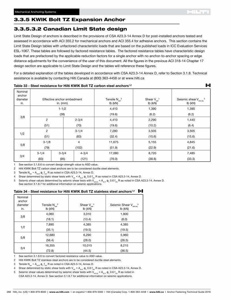
Mechanical Anchoring Systems
3.3.5 KWIK Bolt TZ Expansion Anchor
288 Hilti, Inc. (US) 1-800-879-8000 | www.us.hilti.com I en español 1-800-879-5000 I Hilti (Canada) Corp. 1-800-363-4458 I www.hilti.ca I Anchor Fastening Technical Guide 2016
Limit State Design of anchors is described in the provisions of CSA A23.3-14 Annex D for post-installed anchors tested and assessed in accordance with ACI 355.2 for mechanical anchors and ACI 355.4 for adhesive anchors. This section contains the Limit State Design tables with unfactored characteristic loads that are based on the published loads in ICC Evaluation Services ESL-1067. These tables are followed by factored resistance tables. The factored resistance tables have characteristic design loads that are prefactored by the applicable reduction factors for a single anchor with no anchor-to-anchor spacing or edge distance adjustments for the convenience of the user of this document. All the figures in the previous ACI 318-14 Chapter 17 design section are applicable to Limit State Design and the tables will reference these figures.
For a detailed explanation of the tables developed in accordance with CSA A23.3-14 Annex D, refer to Section 3.1.8. Technical assistance is available by contacting Hilti Canada at (800) 363-4458 or at www.hilti.ca
3.3.5.3.2 Canadian Limit State design
Table 34 - Steel resistance for Hilti KWIK Bolt TZ stainless steel anchors1,2 c
Nominal anchor
diameter in.
Tensile Nsar3
lb (kN)Shear Vsar
4
lb (kN)Seismic Shear Vsar,eq
5
lb (kN)
3/84,060 3,010 1,800(18.1) (13.4) (8.0)
1/27,890 4,385 4,385(35.1) (19.5) (19.5)
5/812,680 6,290 5,960(56.4) (28.0) (26.5)
3/416,355 10,015 8,215(72.8) (44.5) (36.5)
1 See section 3.1.8.6 to convert factored resistance value to ASD value.2 Hilti KWIK Bolt TZ stainless steel anchors are to be considered ductile steel elements.3 Tensile Nsar = Ase,Nфs futa R as noted in CSA A23.3-14, Annex D.4 Shear determined by static shear tests with Vsar < Ase,Vфs 0.6 futa R as noted in CSA A23.3-14, Annex D.5 Seismic shear values determined by seismic shear tests with Vsar,eq < Ase,Vфs 0.6 futa R as noted in CSA A23.3-14, Annex D. See section 3.1.8.7 for additional information on seismic applications.
Table 33 - Steel resistance for Hilti KWIK Bolt TZ carbon steel anchors1,2 c
Nominal anchor
diameter in.
Effective anchor embedment in. (mm)
Tensile Nsar3
lb (kN)Shear Vsar
4
lb (kN)Seismic shear Vsar,eq
5
lb (kN)
3/8
1-1/2 4,410 1,390 1,390
(38) (19.6) (6.2) (6.2)
2 2-3/4 4,410 2,290 1,440
(51) (70) (19.6) (10.2) (6.4)
1/22 3-1/4 7,280 3,505 3,505
(51) (83) (32.4) (15.6) (15.6)
5/83-1/8 4 11,675 5,155 4,845
(79) (102) (51.9) (22.9) (21.6)
3/43-1/4 3-3/4 4-3/4 17,080 8,720 7,485
(83) (95) (121) (76.0) (38.8) (33.3)
1 See section 3.1.8.6 to convert design strength value to ASD value.2 Hilti KWIK Bolt TZ carbon steel anchors are to be considered ductile steel elements.3 Tensile Nsar = Ase,Nфs futa R as noted in CSA A23.3-14, Annex D.4 Shear determined by static shear tests with Vsar < Ase,Vфs 0.6 futa R as noted in CSA A23.3-14, Annex D.5 Seismic shear values determined by seismic shear tests with Vsar,eq < Ase,Vфs 0.6 futa R as noted in CSA A23.3-14, Annex D.
See section 3.1.8.7 for additional information on seismic applications.
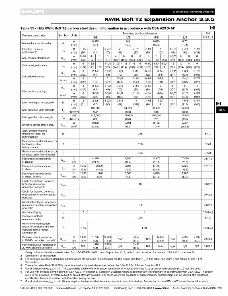
Mechanical Anchoring Systems
KWIK Bolt TZ Expansion Anchor 3.3.5
3.3.9
3.3.9
3.3.9
3.3.9
3.3.1
3.3.2
3.3.3
3.3.9
3.3.6
3.3.7
3.3.8
3.3.9
3.3.9
3.3.4
3.3.5
c
Hilti, Inc. (US) 1-800-879-8000 | www.us.hilti.com I en español 1-800-879-5000 I Hilti (Canada) Corp. 1-800-363-4458 I www.hilti.ca I Anchor Fastening Technical Guide 2016 289
Table 35 - Hilti KWIK Bolt TZ carbon steel design information in accordance with CSA A23.3-141 c
Design parameter Symbol Units Nominal anchor diameter Ref3/8 1/2 5/8 3/4 A23.3-14
Nominal anchor diameter da
in. 0.375 0.5 0.625 0.75(mm) (9.5) (12.7) (15.9) (19.1)
Effective minimum embedment2 hef
in. 1-1/2 2 2-3/4 2 3-1/4 3-1/8 4 3-1/4 3-3/4 4-3/4(mm) (38) (51) (70) (51) (83) (79) (102) (83) (95) (121)
Min. member thickness3 hmin
in. 3-1/4 4 5 5 4 6 6 8 5 6 8 5-1/2 6 8 8(mm) (83) (102) (127) (127) (102) (152) (152) (203) (127) (152) (203) (140) (152) (203) (203)
Critical edge distance cac
in. 6 4-3/8 4 4-1/8 5-1/2 4-1/2 7-1/2 6 6-1/2 8-3/4 6-3/4 12 10 8 9(mm) (152) (111) (102) (105) (140) (114) (191) (152) (165) (222) (171) (305) (254) (203) (229)
Min. edge distancecmin
in. 8 2-1/2 2-1/2 2-3/4 2-3/8 3-5/8 3-1/4 9-1/2 4-3/4 4-1/8(mm) (203) (64) (64) (70) (60) (92) (83) (241) (121) (105)
for s >in. 8 5 5 5-3/4 5-3/4 6-1/8 5-7/8 5 10-1/2 8-7/8
(mm) (203) (127) (127) (146) (146) (156) (149) (127) (267) (225)
Min. anchor spacingsmin
in. 8 2-1/2 2-1/2 2-3/4 2-3/8 3-1/2 3 5 5 4(mm) (203) (64) (64) (70) (60) (89) (76) (127) (127) (102)
for c >in. 8 3-5/8 3-5/8 4-1/8 3-1/2 4-3/4 4-1/4 9-1/2 9-1/2 7-3/4
(mm) (203) (92) (92) (105) (89) (121) (108) (241) (241) (197)
Min. hole depth in concrete ho
in. 2 2-5/8 3-3/8 2-5/8 4 3-7/8 4-3/4 4 4-5/8 5-3/4(mm) (51) (67) (86) (67) (102) (98) (121) (102) (117) (146)
Min.specifiedyieldstrength fya
psi 100,000 84,800 84,800 84,800(N/mm2) (690) (585) (585) (585)
Min.specifiedult.strength futa
psi 125,000 106,000 106,000 106,000(N/mm2) (862) (731) (731) (731)
Effective tensile stress area Ase,N
in2 0.052 0.101 0.162 0.237(mm2) (33.6) (65.0) (104.6) (152.8)
Steel embed. material resistance factor for reinforcement
фs - 0.85 8.4.3
Resistancemodificationfactorfor tension, steel failure modes4
R - 0.80 D.5.3
Resistancemodificationfactorfor shear, steel failure modes4 R - 0.75 D.5.3
Factored steel resistance in tension Nsar
lb 4,410 7,280 11,675 17,080 D.6.1.2(kN) (19.7) (32.4) (51.9) (76.0)
Factored steel resistance in shear Vsar
lb 1,390 2,290 3,505 5,155 8,720 D.7.1.2(kN) (6.2) (10.2) (15.6) (22.9) (38.8)
Factored steel resistance in shear, seismic Vsar,eq
lb 1,390 1,440 3,505 4,845 7,485(kN) (6.2) (6.4) (15.6) (21.6) (33.3)
Coeff. for factored concrete breakout resistance, uncracked concrete
kc,uncr - 10 D.6.2.2
Coeff. for factored concrete breakout resistance, cracked concrete
kc,cr - 7 D.6.2.2
Modification factor for anchor resistance, tension, uncracked concrete5
ψc,N - 1.0 D.6.2.6
Anchor category - - 2 1 D.5.3 (c )Concrete material resistance factor фc - 0.65 8.4.2
Resistancemodificationfactor for tension and shear, concrete failure modes, Condition B6
R - 0.85 1.00 D.5.3 (c )
Factored pullout resistance in 20 MPa uncracked concrete7 Npr,uncr
lb 1,285 1,765 2,880N/A
3,855N/A
6,405N/A
5,795 7,480D.6.3.2
(kN) (5.7) (7.8) (12.8) (17.2) (28.5) (25.8) (33.3)Factored pullout resistance in 20 MPa cracked concrete7 Npr,cr
lbN/A
1,590 2,220N/A
3,450N/A N/A N/A N/A N/A D.6.3.2
(kN) (7.1) (9.9) (15.3)
1 Design information in this table is taken from ICC-ES ESL-1067, dated September 2016, table 3, and converted for use with CSA A23.3-14 Annex D.2 Seefigure1ofthissection.3 Forconcreteovermetaldeckapplicationswheretheconcretethicknessoverthetopfluteislessthanhmininthistable,seefigure6andtables43and44of
this section.4 ThecarbonsteelKWIKBoltTZisconsideredaductilesteelelementasdefinedbyCSAA23.3-14AnnexDsectionD.2.5 Foralldesigncases,ψc,N=1.0.Theappropriatecoefficientforbreakoutresistanceforcrackedconcrete(kc,cr) or uncracked concrete (kc,uncr) must be used.6 For use with the load combinations of CSA A23.3-14 chapter 8. Condition B applies where supplementary reinforcement in conformance with CSA A23.3-14 section
D.5.3isnotprovided,orwherepulloutorpryoutstrengthgoverns.Forcaseswherethepresenceofsupplementaryreinforcementcanbeverified,theresistancemodificationfactorsassociatedwithConditionAmaybeused.
7 Foralldesigncases,ψc,P = 1.0. NA (not applicable) denotes that this value does not control for design. See section 4.1.4 of ESL-1067 for additional information.
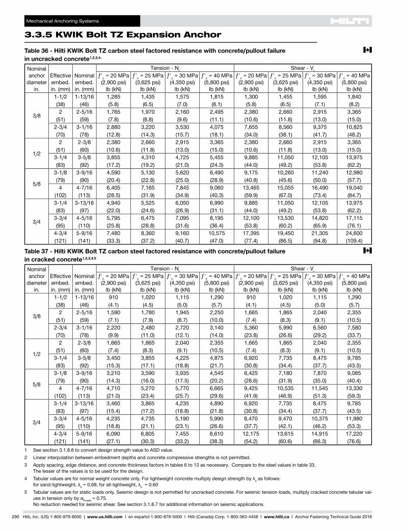
Mechanical Anchoring Systems
3.3.5 KWIK Bolt TZ Expansion Anchor
290 Hilti, Inc. (US) 1-800-879-8000 | www.us.hilti.com I en español 1-800-879-5000 I Hilti (Canada) Corp. 1-800-363-4458 I www.hilti.ca I Anchor Fastening Technical Guide 2016
Table 36 - Hilti KWIK Bolt TZ carbon steel factored resistance with concrete/pullout failure c
in uncracked concrete1,2,3,4.
Nominal anchor
diameter in.
Effective embed. in. (mm)
Nominal embed. in. (mm)
Tension - Nr Shear - Vr
ƒ'c = 20 MPa (2,900 psi)
lb (kN)
ƒ'c = 25 MPa (3,625 psi)
lb (kN)
ƒ'c = 30 MPa (4,350 psi)
lb (kN)
ƒ'c = 40 MPa (5,800 psi)
lb (kN)
ƒ'c = 20 MPa (2,900 psi)
lb (kN)
ƒ'c = 25 MPa (3,625 psi)
lb (kN)
ƒ'c = 30 MPa (4,350 psi)
lb (kN)
ƒ'c = 40 MPa (5,800 psi)
lb (kN)
3/8
1-1/2 1-13/16 1,285 1,435 1,575 1,815 1,300 1,455 1,595 1,840(38) (46) (5.8) (6.5) (7.0) (8.1) (5.8) (6.5) (7.1) (8.2)2 2-5/16 1,765 1,970 2,160 2,495 2,380 2,660 2,915 3,365
(51) (59) (7.8) (8.8) (9.6) (11.1) (10.6) (11.8) (13.0) (15.0)2-3/4 3-1/16 2,880 3,220 3,530 4,075 7,655 8,560 9,375 10,825(70) (78) (12.8) (14.3) (15.7) (18.1) (34.0) (38.1) (41.7) (48.2)
1/2
2 2-3/8 2,380 2,660 2,915 3,365 2,380 2,660 2,915 3,365(51) (60) (10.6) (11.8) (13.0) (15.0) (10.6) (11.8) (13.0) (15.0)
3-1/4 3-5/8 3,855 4,310 4,725 5,455 9,885 11,050 12,105 13,975(83) (92) (17.2) (19.2) (21.0) (24.3) (44.0) (49.2) (53.8) (62.2)
5/8
3-1/8 3-9/16 4,590 5,130 5,620 6,490 9,175 10,260 11,240 12,980(79) (90) (20.4) (22.8) (25.0) (28.9) (40.8) (45.6) (50.0) (57.7)4 4-7/16 6,405 7,165 7,845 9,060 13,465 15,055 16,490 19,040
(102) (113) (28.5) (31.9) (34.9) (40.3) (59.9) (67.0) (73.4) (84.7)
3/4
3-1/4 3-13/16 4,940 5,525 6,050 6,990 9,885 11,050 12,105 13,975(83) (97) (22.0) (24.6) (26.9) (31.1) (44.0) (49.2) (53.8) (62.2)
3-3/4 4-5/16 5,795 6,475 7,095 8,195 12,100 13,530 14,820 17,115(95) (110) (25.8) (28.8) (31.6) (36.4) (53.8) (60.2) (65.9) (76.1)
4-3/4 5-9/16 7,480 8,360 9,160 10,575 17,395 19,450 21,305 24,600(121) (141) (33.3) (37.2) (40.7) (47.0) (77.4) (86.5) (94.8) (109.4)
Table 37 - Hilti KWIK Bolt TZ carbon steel factored resistance with concrete/pullout failure c
in cracked concrete1,2,3,4.5
Nominal anchor
diameter in.
Effective embed. in. (mm)
Nominal embed. in. (mm)
Tension - Nr Shear - Vr
ƒ'c = 20 MPa (2,900 psi)
lb (kN)
ƒ'c = 25 MPa (3,625 psi)
lb (kN)
ƒ'c = 30 MPa (4,350 psi)
lb (kN)
ƒ'c = 40 MPa (5,800 psi)
lb (kN)
ƒ'c = 20 MPa (2,900 psi)
lb (kN)
ƒ'c = 25 MPa (3,625 psi)
lb (kN)
ƒ'c = 30 MPa (4,350 psi)
lb (kN)
ƒ'c = 40 MPa (5,800 psi)
lb (kN)
3/8
1-1/2 1-13/16 910 1,020 1,115 1,290 910 1,020 1,115 1,290(38) (46) (4.1) (4.5) (5.0) (5.7) (4.1) (4.5) (5.0) (5.7)2 2-5/16 1,590 1,780 1,945 2,250 1,665 1,865 2,040 2,355
(51) (59) (7.1) (7.9) (8.7) (10.0) (7.4) (8.3) (9.1) (10.5)2-3/4 3-1/16 2,220 2,480 2,720 3,140 5,360 5,990 6,560 7,580(70) (78) (9.9) (11.0) (12.1) (14.0) (23.8) (26.6) (29.2) (33.7)
1/2
2 2-3/8 1,665 1,865 2,040 2,355 1,665 1,865 2,040 2,355(51) (60) (7.4) (8.3) (9.1) (10.5) (7.4) (8.3) (9.1) (10.5)
3-1/4 3-5/8 3,450 3,855 4,225 4,875 6,920 7,735 8,475 9,785(83) (92) (15.3) (17.1) (18.8) (21.7) (30.8) (34.4) (37.7) (43.5)
5/8
3-1/8 3-9/16 3,210 3,590 3,935 4,545 6,425 7,180 7,870 9,085(79) (90) (14.3) (16.0) (17.5) (20.2) (28.6) (31.9) (35.0) (40.4)4 4-7/16 4,710 5,270 5,770 6,665 9,425 10,535 11,545 13,330
(102) (113) (21.0) (23.4) (25.7) (29.6) (41.9) (46.9) (51.3) (59.3)
3/4
3-1/4 3-13/16 3,460 3,865 4,235 4,890 6,920 7,735 8,475 9,785(83) (97) (15.4) (17.2) (18.8) (21.8) (30.8) (34.4) (37.7) (43.5)
3-3/4 4-5/16 4,235 4,735 5,190 5,990 8,470 9,470 10,375 11,980(95) (110) (18.8) (21.1) (23.1) (26.6) (37.7) (42.1) (46.2) (53.3)
4-3/4 5-9/16 6,090 6,805 7,455 8,610 12,175 13,615 14,915 17,220(121) (141) (27.1) (30.3) (33.2) (38.3) (54.2) (60.6) (66.3) (76.6)
1 See section 3.1.8.6 to convert design strength value to ASD value.2 Linear interpolation between embedment depths and concrete compressive strengths is not permitted.3 Apply spacing, edge distance, and concrete thickness factors in tables 6 to 13 as necessary. Compare to the steel values in table 33.
The lesser of the values is to be used for the design.4 Tabularvaluesarefornormalweightconcreteonly.Forlightweightconcretemultiplydesignstrengthbyλa as follows:
forsand-lightweight,λa=0.68;forall-lightweight,λa = 0.605 Tabular values are for static loads only. Seismic design is not permitted for uncracked concrete. For seismic tension loads, multiply cracked concrete tabular val-
uesintensiononlybyαN,seis = 0.75. No reduction needed for seismic shear. See section 3.1.8.7 for additional information on seismic applications.
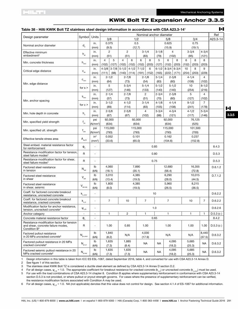
Mechanical Anchoring Systems
KWIK Bolt TZ Expansion Anchor 3.3.5
3.3.9
3.3.9
3.3.9
3.3.9
3.3.1
3.3.2
3.3.3
3.3.9
3.3.6
3.3.7
3.3.8
3.3.9
3.3.9
3.3.4
3.3.5
c
Hilti, Inc. (US) 1-800-879-8000 | www.us.hilti.com I en español 1-800-879-5000 I Hilti (Canada) Corp. 1-800-363-4458 I www.hilti.ca I Anchor Fastening Technical Guide 2016 291
Table 38 - Hilti KWIK Bolt TZ stainless steel design information in accordance with CSA A23.3-141 c
Design parameter Symbol Units Nominal anchor diameter Ref3/8 1/2 5/8 3/4 A23.3-14
Nominal anchor diameter da
in. 0.375 0.5 0.625 0.75(mm) (9.5) (12.7) (15.9) (19.1)
Effective minimum embedment2 hef
in. 2 2 3-1/4 3-1/8 4 3-3/4 4-3/4(mm) (51) (51) (83) (79) (102) (95) (121)
Min. concrete thickness hmin
in. 4 5 4 6 6 8 5 6 8 6 8 8(mm) (102) (127) (102) (152) (152) (203) (127) (152) (203) (152) (203) (203)
Critical edge distance cac
in. 4-3/8 3-7/8 5-1/2 4-1/2 7-1/2 6 6-1/2 8-3/4 6-3/4 10 8 9(mm) (111) (98) (140) (114) (191) (152) (165) (222) (171) (254) (203) (229)
Min. edge distancecmin
in. 2-1/2 2-7/8 2-1/8 3-1/4 2-3/8 4-1/4 4(mm) (64) (73) (54) (83) (60) (108) (102)
for s >in. 5 5-3/4 5-1/4 5-1/2 5-1/2 10 8-1/2
(mm) (127) (146) (133) (140) (140) (254) (216)
Min. anchor spacingsmin
in. 2-1/4 2-7/8 2 2-3/4 2-3/8 5 4(mm) (57) (73) (51) (70) (60) (127) (102)
for c >in. 3-1/2 4-1/2 3-1/4 4-1/8 4-1/4 9-1/2 7
(mm) (89) (114) (83) (105) (108) (241) (178)
Min. hole depth in concrete ho
in. 2-5/8 2-5/8 4 3-3/4 4-3/4 4-1/2 5-3/4(mm) (67) (67) (102) (98) (121) (117) (146)
Min.specifiedyieldstrength fya
psi 92,000 92,000 92,000 76,125(N/mm2) (634) (634) (634) (525)
Min.specifiedult.strength futa
psi 115,000 115,000 115,000 101,500(N/mm2) (793) (793) (793) (700)
Effective tensile stress area Ase,N
in2 0.052 0.101 0.162 0.237(mm2) (33.6) (65.0) (104.6) (152.8)
Steel embed. material resistance factor for reinforcement фs - 0.85 8.4.3
Resistancemodificationfactorfortension,steel failure modes3 R - 0.80 D.5.3
Resistancemodificationfactorforshear, steel failure modes3 R - 0.75 D.5.3
Factored steel resistance in tension Nsar
lb 4,060 7,890 12,680 16,355 D.6.1.2(kN) (18.1) (35.1) (56.4) (72.8)
Factored steel resistance in shear Vsar
lb 3,010 4,385 6,290 10,015 D.7.1.2(kN) (13.4) (19.5) (28.0) (44.5)
Factored steel resistance in shear, seismic Vsar,eq
lb 1,800 4,385 5,960 8,215(kN) (8.0) (19.5) (26.5) (36.5)
Coeff. for factored concrete breakout resistance, uncracked concrete kc,uncr - 10 D.6.2.2
Coeff. for factored concrete breakout resistance, cracked concrete kc,cr - 7 10 7 7 10 7 D.6.2.2
Modification factor for anchor resistance, tension, uncracked concrete4 ψc,N - 1.0 D.6.2.6
Anchor category - - 1 2 1 1 1 1 D.5.3 (c )Concrete material resistance factor фc - 0.65 8.4.2Resistancemodificationfactorfortensionand shear, concrete failure modes, Condition B5
R - 1.00 0.85 1.00 1.00 1.00 1.00 D.5.3 (c )
Factored pullout resistance in 20 MPa uncracked concrete6 Npr,uncr
lb 1,840N/A
4,030N/A N/A
8,440D.6.3.2
(kN) (8.2) (17.9) (37.5)Factored pullout resistance in 20 MPa cracked concrete6 Npr,cr
lb 1,635 1,885NA NA
4,095 5,685NA D.6.3.2
(kN) (7.3) (8.4) (18.2) (25.3)Factored seismic pullout resistance in 20 MPa cracked concrete6 Npr,eq
lb 1,635 1,635NA NA
4,095 5,685NA D.6.3.2
(kN) (7.3) (7.3) (18.2) (25.3)
1 Design information in this table is taken from ICC ES ESL-1067, dated September 2016, table 4, and converted for use with CSA A23.3-14 Annex D.2 Seefigure1ofthissection.3 ThestainlesssteelKWIKBoltTZisconsideredaductilesteelelementasdefinedbyCSAA23.3-14AnnexDsectionD.2.4 Foralldesigncases,ψc,N=1.0.Theappropriatecoefficientforbreakoutresistanceforcrackedconcrete(kc,cr) or uncracked concrete (kc,uncr) must be used.5 For use with the load combinations of CSA A23.3-14 chapter 8. Condition B applies where supplementary reinforcement in conformance with CSA A23.3-14
sectionD.5.3isnotprovided,orwherepulloutorpryoutstrengthgoverns.Forcaseswherethepresenceofsupplementaryreinforcementcanbeverified, theresistancemodificationfactorsassociatedwithConditionAmaybeused.
6 Foralldesigncases,ψc,P = 1.0. NA (not applicable) denotes that this value does not control for design. See section 4.1.4 of ES-1067 for additional information.
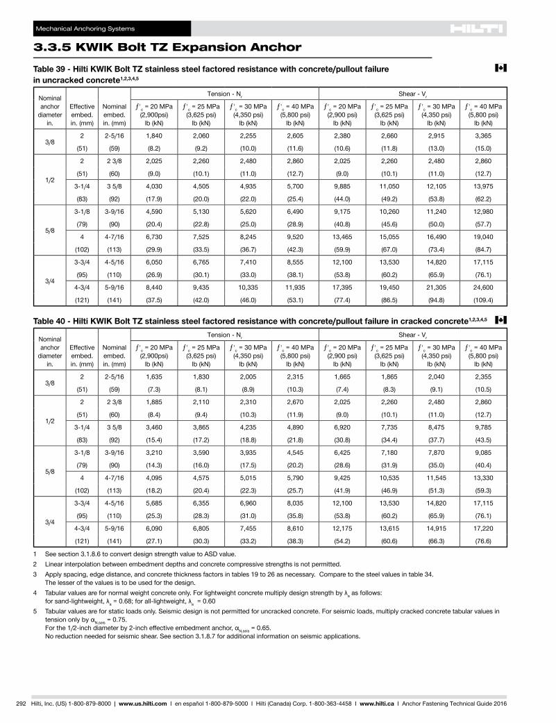
Mechanical Anchoring Systems
3.3.5 KWIK Bolt TZ Expansion Anchor
292 Hilti, Inc. (US) 1-800-879-8000 | www.us.hilti.com I en español 1-800-879-5000 I Hilti (Canada) Corp. 1-800-363-4458 I www.hilti.ca I Anchor Fastening Technical Guide 2016
Table 39 - Hilti KWIK Bolt TZ stainless steel factored resistance with concrete/pullout failure c
in uncracked concrete1,2,3,4,5
Nominal anchor
diameter in.
Effective embed. in. (mm)
Nominal embed. in. (mm)
Tension - Nr Shear - Vr
ƒ'c = 20 MPa (2,900psi)
lb (kN)
ƒ'c = 25 MPa (3,625 psi)
lb (kN)
ƒ'c = 30 MPa (4,350 psi)
lb (kN)
ƒ'c = 40 MPa (5,800 psi)
lb (kN)
ƒ'c = 20 MPa (2,900 psi)
lb (kN)
ƒ'c = 25 MPa (3,625 psi)
lb (kN)
ƒ'c = 30 MPa (4,350 psi)
lb (kN)
ƒ'c = 40 MPa (5,800 psi)
lb (kN)
3/82 2-5/16 1,840 2,060 2,255 2,605 2,380 2,660 2,915 3,365
(51) (59) (8.2) (9.2) (10.0) (11.6) (10.6) (11.8) (13.0) (15.0)
1/2
2 2 3/8 2,025 2,260 2,480 2,860 2,025 2,260 2,480 2,860
(51) (60) (9.0) (10.1) (11.0) (12.7) (9.0) (10.1) (11.0) (12.7)
3-1/4 3 5/8 4,030 4,505 4,935 5,700 9,885 11,050 12,105 13,975
(83) (92) (17.9) (20.0) (22.0) (25.4) (44.0) (49.2) (53.8) (62.2)
5/8
3-1/8 3-9/16 4,590 5,130 5,620 6,490 9,175 10,260 11,240 12,980
(79) (90) (20.4) (22.8) (25.0) (28.9) (40.8) (45.6) (50.0) (57.7)
4 4-7/16 6,730 7,525 8,245 9,520 13,465 15,055 16,490 19,040
(102) (113) (29.9) (33.5) (36.7) (42.3) (59.9) (67.0) (73.4) (84.7)
3/4
3-3/4 4-5/16 6,050 6,765 7,410 8,555 12,100 13,530 14,820 17,115
(95) (110) (26.9) (30.1) (33.0) (38.1) (53.8) (60.2) (65.9) (76.1)
4-3/4 5-9/16 8,440 9,435 10,335 11,935 17,395 19,450 21,305 24,600
(121) (141) (37.5) (42.0) (46.0) (53.1) (77.4) (86.5) (94.8) (109.4)
Table 40 - Hilti KWIK Bolt TZ stainless steel factored resistance with concrete/pullout failure in cracked concrete1,2,3,4,5 c
Nominal anchor
diameter in.
Effective embed. in. (mm)
Nominal embed. in. (mm)
Tension - Nr Shear - Vr
ƒ'c = 20 MPa (2,900psi)
lb (kN)
ƒ'c = 25 MPa (3,625 psi)
lb (kN)
ƒ'c = 30 MPa (4,350 psi)
lb (kN)
ƒ'c = 40 MPa (5,800 psi)
lb (kN)
ƒ'c = 20 MPa (2,900 psi)
lb (kN)
ƒ'c = 25 MPa (3,625 psi)
lb (kN)
ƒ'c = 30 MPa (4,350 psi)
lb (kN)
ƒ'c = 40 MPa (5,800 psi)
lb (kN)
3/82 2-5/16 1,635 1,830 2,005 2,315 1,665 1,865 2,040 2,355
(51) (59) (7.3) (8.1) (8.9) (10.3) (7.4) (8.3) (9.1) (10.5)
1/2
2 2 3/8 1,885 2,110 2,310 2,670 2,025 2,260 2,480 2,860
(51) (60) (8.4) (9.4) (10.3) (11.9) (9.0) (10.1) (11.0) (12.7)
3-1/4 3 5/8 3,460 3,865 4,235 4,890 6,920 7,735 8,475 9,785
(83) (92) (15.4) (17.2) (18.8) (21.8) (30.8) (34.4) (37.7) (43.5)
5/8
3-1/8 3-9/16 3,210 3,590 3,935 4,545 6,425 7,180 7,870 9,085
(79) (90) (14.3) (16.0) (17.5) (20.2) (28.6) (31.9) (35.0) (40.4)
4 4-7/16 4,095 4,575 5,015 5,790 9,425 10,535 11,545 13,330
(102) (113) (18.2) (20.4) (22.3) (25.7) (41.9) (46.9) (51.3) (59.3)
3/4
3-3/4 4-5/16 5,685 6,355 6,960 8,035 12,100 13,530 14,820 17,115
(95) (110) (25.3) (28.3) (31.0) (35.8) (53.8) (60.2) (65.9) (76.1)
4-3/4 5-9/16 6,090 6,805 7,455 8,610 12,175 13,615 14,915 17,220
(121) (141) (27.1) (30.3) (33.2) (38.3) (54.2) (60.6) (66.3) (76.6)
1 See section 3.1.8.6 to convert design strength value to ASD value.2 Linear interpolation between embedment depths and concrete compressive strengths is not permitted.3 Apply spacing, edge distance, and concrete thickness factors in tables 19 to 26 as necessary. Compare to the steel values in table 34.
The lesser of the values is to be used for the design.4 Tabularvaluesarefornormalweightconcreteonly.Forlightweightconcretemultiplydesignstrengthbyλa as follows:
forsand-lightweight,λa=0.68;forall-lightweight,λa = 0.605 Tabular values are for static loads only. Seismic design is not permitted for uncracked concrete. For seismic loads, multiply cracked concrete tabular values in
tensiononlybyαN,seis = 0.75. Forthe1/2-inchdiameterby2-incheffectiveembedmentanchor,αN,seis = 0.65. No reduction needed for seismic shear. See section 3.1.8.7 for additional information on seismic applications.
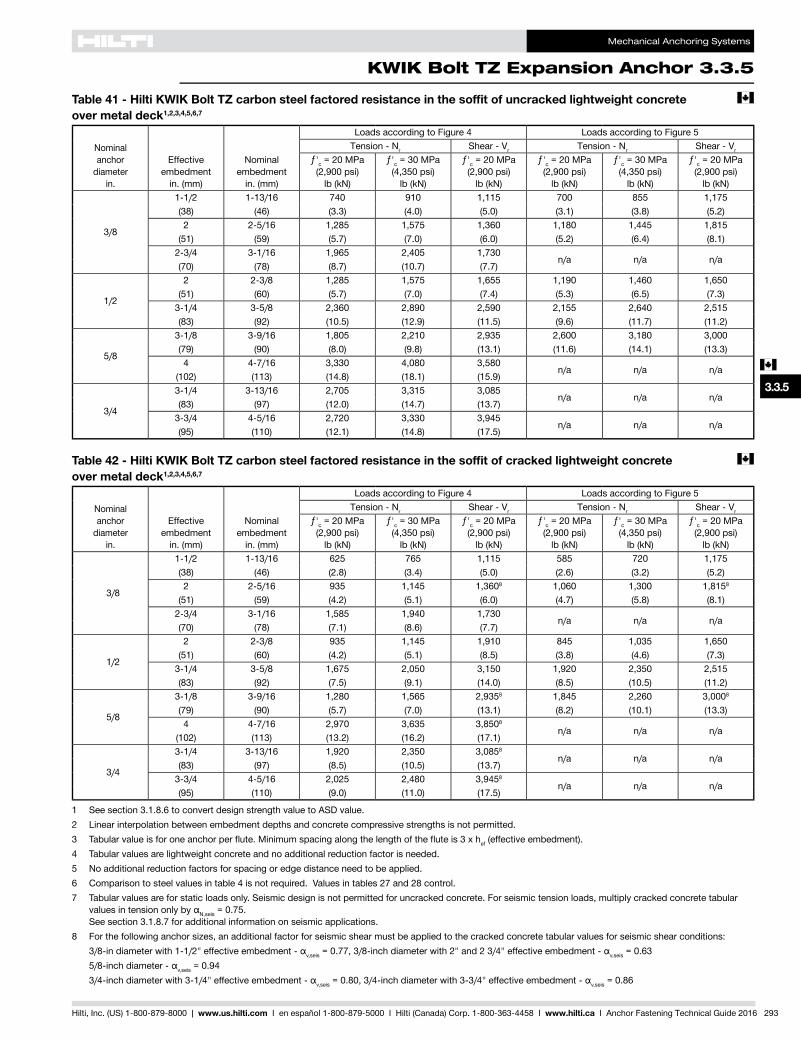
Mechanical Anchoring Systems
KWIK Bolt TZ Expansion Anchor 3.3.5
3.3.9
3.3.9
3.3.9
3.3.9
3.3.1
3.3.2
3.3.3
3.3.9
3.3.6
3.3.7
3.3.8
3.3.9
3.3.9
3.3.4
3.3.5
c
Hilti, Inc. (US) 1-800-879-8000 | www.us.hilti.com I en español 1-800-879-5000 I Hilti (Canada) Corp. 1-800-363-4458 I www.hilti.ca I Anchor Fastening Technical Guide 2016 293
Table 41 - Hilti KWIK Bolt TZ carbon steel factored resistance in the soffit of uncracked lightweight concrete c
over metal deck1,2,3,4,5,6,7
Nominal anchor
diameter in.
Effective embedment
in. (mm)
Nominal embedment
in. (mm)
Loads according to Figure 4 Loads according to Figure 5Tension - Nr Shear - Vr Tension - Nr Shear - Vr
ƒ'c = 20 MPa (2,900 psi)
lb (kN)
ƒ'c = 30 MPa (4,350 psi)
lb (kN)
ƒ'c = 20 MPa (2,900 psi)
lb (kN)
ƒ'c = 20 MPa (2,900 psi)
lb (kN)
ƒ'c = 30 MPa (4,350 psi)
lb (kN)
ƒ'c = 20 MPa (2,900 psi)
lb (kN)
3/8
1-1/2 1-13/16 740 910 1,115 700 855 1,175(38) (46) (3.3) (4.0) (5.0) (3.1) (3.8) (5.2)2 2-5/16 1,285 1,575 1,360 1,180 1,445 1,815
(51) (59) (5.7) (7.0) (6.0) (5.2) (6.4) (8.1)2-3/4 3-1/16 1,965 2,405 1,730
n/a n/a n/a(70) (78) (8.7) (10.7) (7.7)
1/2
2 2-3/8 1,285 1,575 1,655 1,190 1,460 1,650(51) (60) (5.7) (7.0) (7.4) (5.3) (6.5) (7.3)
3-1/4 3-5/8 2,360 2,890 2,590 2,155 2,640 2,515(83) (92) (10.5) (12.9) (11.5) (9.6) (11.7) (11.2)
5/8
3-1/8 3-9/16 1,805 2,210 2,935 2,600 3,180 3,000(79) (90) (8.0) (9.8) (13.1) (11.6) (14.1) (13.3)4 4-7/16 3,330 4,080 3,580
n/a n/a n/a(102) (113) (14.8) (18.1) (15.9)
3/4
3-1/4 3-13/16 2,705 3,315 3,085n/a n/a n/a
(83) (97) (12.0) (14.7) (13.7)3-3/4 4-5/16 2,720 3,330 3,945
n/a n/a n/a(95) (110) (12.1) (14.8) (17.5)
Table 42 - Hilti KWIK Bolt TZ carbon steel factored resistance in the soffit of cracked lightweight concrete c over metal deck1,2,3,4,5,6,7
Nominal anchor
diameter in.
Effective embedment
in. (mm)
Nominal embedment
in. (mm)
Loads according to Figure 4 Loads according to Figure 5Tension - Nr Shear - Vr Tension - Nr Shear - Vr
ƒ'c = 20 MPa (2,900 psi)
lb (kN)
ƒ'c = 30 MPa (4,350 psi)
lb (kN)
ƒ'c = 20 MPa (2,900 psi)
lb (kN)
ƒ'c = 20 MPa (2,900 psi)
lb (kN)
ƒ'c = 30 MPa (4,350 psi)
lb (kN)
ƒ'c = 20 MPa (2,900 psi)
lb (kN)
3/8
1-1/2 1-13/16 625 765 1,115 585 720 1,175(38) (46) (2.8) (3.4) (5.0) (2.6) (3.2) (5.2)2 2-5/16 935 1,145 1,3608 1,060 1,300 1,8158
(51) (59) (4.2) (5.1) (6.0) (4.7) (5.8) (8.1)2-3/4 3-1/16 1,585 1,940 1,730
n/a n/a n/a(70) (78) (7.1) (8.6) (7.7)
1/2
2 2-3/8 935 1,145 1,910 845 1,035 1,650(51) (60) (4.2) (5.1) (8.5) (3.8) (4.6) (7.3)
3-1/4 3-5/8 1,675 2,050 3,150 1,920 2,350 2,515(83) (92) (7.5) (9.1) (14.0) (8.5) (10.5) (11.2)
5/8
3-1/8 3-9/16 1,280 1,565 2,9358 1,845 2,260 3,0008
(79) (90) (5.7) (7.0) (13.1) (8.2) (10.1) (13.3)4 4-7/16 2,970 3,635 3,8508
n/a n/a n/a(102) (113) (13.2) (16.2) (17.1)
3/4
3-1/4 3-13/16 1,920 2,350 3,0858
n/a n/a n/a(83) (97) (8.5) (10.5) (13.7)
3-3/4 4-5/16 2,025 2,480 3,9458
n/a n/a n/a(95) (110) (9.0) (11.0) (17.5)
1 See section 3.1.8.6 to convert design strength value to ASD value.2 Linear interpolation between embedment depths and concrete compressive strengths is not permitted.3 Tabularvalueisforoneanchorperflute.Minimumspacingalongthelengthofthefluteis3xhef (effective embedment).4 Tabular values are lightweight concrete and no additional reduction factor is needed.5 No additional reduction factors for spacing or edge distance need to be applied.6 Comparison to steel values in table 4 is not required. Values in tables 27 and 28 control.7 Tabular values are for static loads only. Seismic design is not permitted for uncracked concrete. For seismic tension loads, multiply cracked concrete tabular
valuesintensiononlybyαN,seis = 0.75. See section 3.1.8.7 for additional information on seismic applications.
8 For the following anchor sizes, an additional factor for seismic shear must be applied to the cracked concrete tabular values for seismic shear conditions: 3/8-indiameterwith1-1/2"effectiveembedment-αv,seis=0.77,3/8-inchdiameterwith2"and23/4"effectiveembedment-αv,seis = 0.63 5/8-inchdiameter-αv,seis = 0.94 3/4-inchdiameterwith3-1/4"effectiveembedment-αv,seis=0.80,3/4-inchdiameterwith3-3/4"effectiveembedment-αv,seis = 0.86
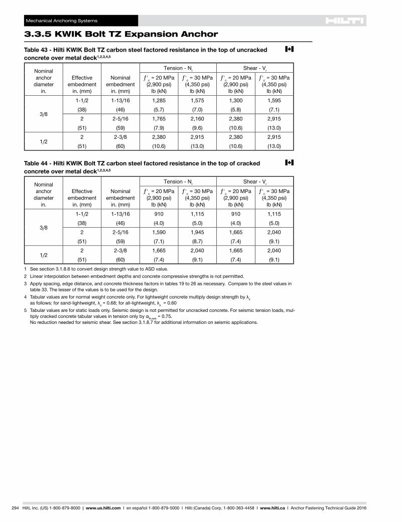
Mechanical Anchoring Systems
3.3.5 KWIK Bolt TZ Expansion Anchor
294 Hilti, Inc. (US) 1-800-879-8000 | www.us.hilti.com I en español 1-800-879-5000 I Hilti (Canada) Corp. 1-800-363-4458 I www.hilti.ca I Anchor Fastening Technical Guide 2016
Table 43 - Hilti KWIK Bolt TZ carbon steel factored resistance in the top of uncracked c concrete over metal deck1,2,3,4,5
Nominal anchor
diameter in.
Effective embedment
in. (mm)
Nominal embedment
in. (mm)
Tension - Nr Shear - Vr
ƒ'c = 20 MPa (2,900 psi)
lb (kN)
ƒ'c = 30 MPa (4,350 psi)
lb (kN)
ƒ'c = 20 MPa (2,900 psi)
lb (kN)
ƒ'c = 30 MPa (4,350 psi)
lb (kN)
3/8
1-1/2 1-13/16 1,285 1,575 1,300 1,595(38) (46) (5.7) (7.0) (5.8) (7.1)2 2-5/16 1,765 2,160 2,380 2,915
(51) (59) (7.9) (9.6) (10.6) (13.0)
1/22 2-3/8 2,380 2,915 2,380 2,915
(51) (60) (10.6) (13.0) (10.6) (13.0)
Table 44 - Hilti KWIK Bolt TZ carbon steel factored resistance in the top of cracked c concrete over metal deck1,2,3,4,5
Nominal anchor
diameter in.
Effective embedment
in. (mm)
Nominal embedment
in. (mm)
Tension - Nr Shear - Vr
ƒ'c = 20 MPa (2,900 psi)
lb (kN)
ƒ'c = 30 MPa (4,350 psi)
lb (kN)
ƒ'c = 20 MPa (2,900 psi)
lb (kN)
ƒ'c = 30 MPa (4,350 psi)
lb (kN)
3/8
1-1/2 1-13/16 910 1,115 910 1,115(38) (46) (4.0) (5.0) (4.0) (5.0)2 2-5/16 1,590 1,945 1,665 2,040
(51) (59) (7.1) (8.7) (7.4) (9.1)
1/22 2-3/8 1,665 2,040 1,665 2,040
(51) (60) (7.4) (9.1) (7.4) (9.1)1 See section 3.1.8.6 to convert design strength value to ASD value.2 Linear interpolation between embedment depths and concrete compressive strengths is not permitted.3 Apply spacing, edge distance, and concrete thickness factors in tables 19 to 26 as necessary. Compare to the steel values in
table 33. The lesser of the values is to be used for the design.4 Tabularvaluesarefornormalweightconcreteonly.Forlightweightconcretemultiplydesignstrengthbyλa
asfollows:forsand-lightweight,λa=0.68;forall-lightweight,λa = 0.605 Tabular values are for static loads only. Seismic design is not permitted for uncracked concrete. For seismic tension loads, mul-
tiplycrackedconcretetabularvaluesintensiononlybyαN,seis = 0.75. No reduction needed for seismic shear. See section 3.1.8.7 for additional information on seismic applications.
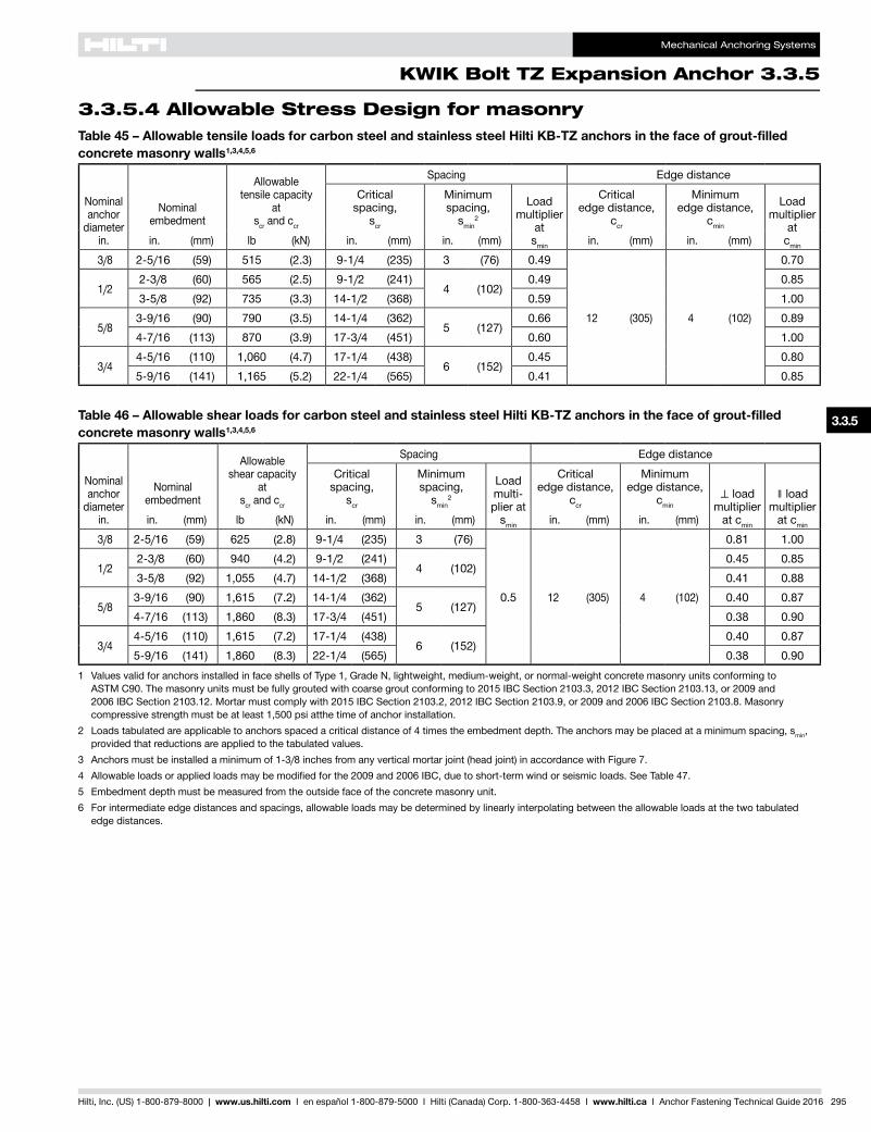
Mechanical Anchoring Systems
KWIK Bolt TZ Expansion Anchor 3.3.5
3.3.9
3.3.9
3.3.9
3.3.9
3.3.1
3.3.2
3.3.3
3.3.9
3.3.5
3.3.6
3.3.7
3.3.8
3.3.9
3.3.9
3.3.4
Hilti, Inc. (US) 1-800-879-8000 | www.us.hilti.com I en español 1-800-879-5000 I Hilti (Canada) Corp. 1-800-363-4458 I www.hilti.ca I Anchor Fastening Technical Guide 2016 295
Table 45 – Allowable tensile loads for carbon steel and stainless steel Hilti KB-TZ anchors in the face of grout-filled concrete masonry walls1,3,4,5,6
Nominal anchor
diameter in.
Nominal embedment
Allowable tensile capacity
at scr and ccr
Spacing Edge distanceCritical
spacing, scr
Minimum spacing,
smin2
Load multiplier
at smin
Critical edge distance,
ccr
Minimum edge distance,
cmin
Load multiplier
at cmin in. (mm) lb (kN) in. (mm) in. (mm) in. (mm) in. (mm)
3/8 2-5/16 (59) 515 (2.3) 9-1/4 (235) 3 (76) 0.49
12 (305) 4 (102)
0.70
1/22-3/8 (60) 565 (2.5) 9-1/2 (241)
4 (102)0.49 0.85
3-5/8 (92) 735 (3.3) 14-1/2 (368) 0.59 1.00
5/83-9/16 (90) 790 (3.5) 14-1/4 (362)
5 (127)0.66 0.89
4-7/16 (113) 870 (3.9) 17-3/4 (451) 0.60 1.00
3/44-5/16 (110) 1,060 (4.7) 17-1/4 (438)
6 (152)0.45 0.80
5-9/16 (141) 1,165 (5.2) 22-1/4 (565) 0.41 0.85
Table 46 – Allowable shear loads for carbon steel and stainless steel Hilti KB-TZ anchors in the face of grout-filled concrete masonry walls1,3,4,5,6
Nominal anchor
diameter in.
Nominal embedment
Allowable shear capacity
at scr and ccr
Spacing Edge distanceCritical
spacing, scr
Minimum spacing,
smin2
Load multi-plier at
smin
Critical edge distance,
ccr
Minimum edge distance,
cmin⊥ load
multiplier at cmin
∥ load multiplier
at cmin in. (mm) lb (kN) in. (mm) in. (mm) in. (mm) in. (mm) 3/8 2-5/16 (59) 625 (2.8) 9-1/4 (235) 3 (76)
0.5 12 (305) 4 (102)
0.81 1.00
1/22-3/8 (60) 940 (4.2) 9-1/2 (241)
4 (102)0.45 0.85
3-5/8 (92) 1,055 (4.7) 14-1/2 (368) 0.41 0.88
5/83-9/16 (90) 1,615 (7.2) 14-1/4 (362)
5 (127)0.40 0.87
4-7/16 (113) 1,860 (8.3) 17-3/4 (451) 0.38 0.90
3/44-5/16 (110) 1,615 (7.2) 17-1/4 (438)
6 (152)0.40 0.87
5-9/16 (141) 1,860 (8.3) 22-1/4 (565) 0.38 0.901 Values valid for anchors installed in face shells of Type 1, Grade N, lightweight, medium-weight, or normal-weight concrete masonry units conforming to
ASTM C90. The masonry units must be fully grouted with coarse grout conforming to 2015 IBC Section 2103.3, 2012 IBC Section 2103.13, or 2009 and 2006 IBC Section 2103.12. Mortar must comply with 2015 IBC Section 2103.2, 2012 IBC Section 2103.9, or 2009 and 2006 IBC Section 2103.8. Masonry compressive strength must be at least 1,500 psi atthe time of anchor installation.
2 Loads tabulated are applicable to anchors spaced a critical distance of 4 times the embedment depth. The anchors may be placed at a minimum spacing, smin, provided that reductions are applied to the tabulated values.
3 Anchors must be installed a minimum of 1-3/8 inches from any vertical mortar joint (head joint) in accordance with Figure 7.4 Allowable loads or applied loads may be modified for the 2009 and 2006 IBC, due to short-term wind or seismic loads. See Table 47.5 Embedment depth must be measured from the outside face of the concrete masonry unit.6 For intermediate edge distances and spacings, allowable loads may be determined by linearly interpolating between the allowable loads at the two tabulated
edge distances.
3.3.5.4 Allowable Stress Design for masonry
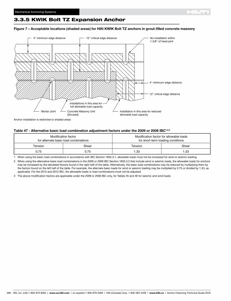
Mechanical Anchoring Systems
3.3.5 KWIK Bolt TZ Expansion Anchor
296 Hilti, Inc. (US) 1-800-879-8000 | www.us.hilti.com I en español 1-800-879-5000 I Hilti (Canada) Corp. 1-800-363-4458 I www.hilti.ca I Anchor Fastening Technical Guide 2016
Figure 7 – Acceptable locations (shaded areas) for Hilti KWIK Bolt TZ anchors in grout-filled concrete masonry
Table 47 - Alternative basic load combination adjustment factors under the 2009 or 2006 IBC1,2,3
Modification factor for alternate basic load combinations
Modification factor for allowable loads for short-term loading conditions
Tension Shear Tension Shear
0.75 0.75 1.33 1.33
1 When using the basic load combinations in accordance with IBC Section 1605.3.1, allowable loads must not be increased for wind or seismic loading.2 When using the alternative basic load combinations in the 2009 or 2006 IBC Section 1605.3.2 that include wind or seismic loads, the allowable loads for anchors
may be increased by the tabulated factors found in the right half of the table. Alternatively, the basic load combinations may be reduced by multiplying them by the factors found on the left half of the table. For example, the alternate basic loads for wind or seismic loading may be multiplied by 0.75 or divided by 1.33, as applicable. For the 2015 and 2012 IBC, the allowable loads or load combinations must not be adjusted.
3 The above modification factors are applicable under the 2009 or 2006 IBC only, for Tables 45 and 46 for seismic and wind loads.
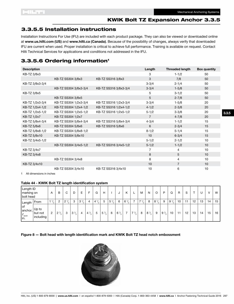
Mechanical Anchoring Systems
KWIK Bolt TZ Expansion Anchor 3.3.5
3.3.9
3.3.9
3.3.9
3.3.9
3.3.1
3.3.2
3.3.3
3.3.9
3.3.5
3.3.6
3.3.7
3.3.8
3.3.9
3.3.9
3.3.4
Hilti, Inc. (US) 1-800-879-8000 | www.us.hilti.com I en español 1-800-879-5000 I Hilti (Canada) Corp. 1-800-363-4458 I www.hilti.ca I Anchor Fastening Technical Guide 2016 297
Figure 8 — Bolt head with length identification mark and KWIK Bolt TZ head notch embossment
Table 44 - KWIK Bolt TZ length identification systemLength ID marking on bolt head
A B C D E F G H I J K L M N O P Q R S T U V W
Length of anchor, ℓanch in.
From 1 1⁄2 2 2 1⁄2 3 3 1⁄2 4 4 1⁄2 5 5 1⁄2 6 6 1⁄2 7 7 1⁄2 8 8 1⁄2 9 9 1⁄2 10 11 12 13 14 15
Up to but not including
2 2 1⁄2 3 3 1⁄2 4 4 1⁄2 5 5 1⁄2 6 6 1⁄2 7 7 1⁄2 8 8 1⁄2 9 9 1⁄2 10 11 12 13 14 15 16
3.3.5.6 Ordering information1
Description Length Threaded length Box quantityKB-TZ 3/8x3 3 1-1/2 50
KB-TZ SS304 3/8x3 KB-TZ SS316 3/8x3 3 7/8 50KB-TZ 3/8x3-3/4 3-3/4 2-1/4 50
KB-TZ SS304 3/8x3-3/4 KB-TZ SS316 3/8x3-3/4 3-3/4 1-5/8 50KB-TZ 3/8x5 5 3-1/2 50
KB-TZ SS304 3/8x5 5 2-7/8 50KB-TZ 1/2x3-3/4 KB-TZ SS304 1/2x3-3/4 KB-TZ SS316 1/2x3-3/4 3-3/4 1-5/8 20KB-TZ 1/2x4-1/2 KB-TZ SS304 1/2x4-1/2 KB-TZ SS316 1/2x4-1/2 4-1/2 2-3/8 20KB-TZ 1/2x5-1/2 KB-TZ SS304 1/2x5-1/2 KB-TZ SS316 1/2x5-1/2 5-1/2 3-3/8 20KB-TZ 1/2x7 KB-TZ SS304 1/2x7 7 4-7/8 20KB-TZ 5/8x4-3/4 KB-TZ SS304 5/8x4-3/4 KB-TZ SS316 5/8x4-3/4 4-3/4 1-1/2 15KB-TZ 5/8x6 KB-TZ SS304 5/8x6 KB-TZ SS316 5/8x6 6 2-3/4 15KB-TZ 5/8x8-1/2 KB-TZ SS304 5/8x8-1/2 8-1/2 5-1/4 15KB-TZ 5/8x10 KB-TZ SS304 5/8x10 10 6-3/4 15KB-TZ 3/4x5-1/2 5-1/2 2-1/2 10
KB-TZ SS304 3/4x5-1/2 KB-TZ SS316 3/4x5-1/2 5-1/2 1-1/2 10KB-TZ 3/4x7 7 4 10KB-TZ 3/4x8 8 5 10
KB-TZ SS304 3/4x8 8 4 10KB-TZ 3/4x10 10 7 10
KB-TZ SS304 3/4x10 KB-TZ SS316 3/4x10 10 6 101 All dimensions in inches
Installation Instructions For Use (IFU) are included with each product package. They can also be viewed or downloaded online at www.us.hilti.com (US) and www.hilti.ca (Canada). Because of the possibility of changes, always verify that downloaded IFU are current when used. Proper installation is critical to achieve full performance. Training is available on request. Contact Hilti Technical Services for applications and conditions not addressed in the IFU.
3.3.5.5 Installation instructions