Embed Size (px)
Citation preview
HILTI HSL-3EXPANSION ANCHOR
ETA-02/0043 (22.11.2017)
Français English
2-3839-75

Centre Scientifique et
Technique du Bâtiment 84 avenue Jean Jaurès CHAMPS-SUR-MARNE F-77447 Marne-la-Vallée Cedex 2
Tél. : (33) 01 64 68 82 82 Fax : (33) 01 60 05 70 37
Member of
www.eota.eu
Evaluation Technique Européenne
ETE-02/0042 du 22/11/2017
(Version originale en langue française)
Partie Générale
Nom commercial Trade name
Hilti HSL-3, HSL-3-R
Famille de produit Product family
Cheville métallique à expansion par vissage à couple contrôlé, pour béton fissuré et non fissuré
Torque-controlled expansion anchor for use in cracked and non-cracked concrete
Titulaire Manufacturer
Hilti Corporation Feldkircherstrasse 100 FL-9494 Schaan Principality of Liechtenstein
Usine de fabrication Manufacturing plants
Usine Hilti
Cette évaluation contient: This assessment contains
37 pages incluant 34 pages d’annexes qui font partie intégrante de cette évaluation 37 pages including 34 pages of annexes which form an integral part of this assessment
Base de l‘ETE Basis of ETA
DEE 330232-00-0601 “Ancrages mécaniques dans le béton”
EAD 330232-00-0601 “Mechanical fasteners for use in concrete”
Cette évaluation remplace: This assessment replaces
ETE-0 2 / 0 0 4 2 délivrée le 07/09/2015 ETA-0 2 / 0 0 4 2 issued on 07/09/2015
Les traductions de cette Evaluation Technique Européenne dans d'autres langues doivent correspondre pleinement au document original et doivent être identifiées comme telles. La communication de cette évaluation technique européenne, y compris la transmission par voie électronique, doit être complète. Cependant, une reproduction partielle peut être faite, avec le consentement écrit de l'organisme d'évaluation technique d'émission. Toute reproduction partielle doit être identifiée comme telle.
Evaluation Technique Européenne ETE - 0 2 / 0 0 4 2
Page 2 de 37 | 22/11/2017
Partie spécifique
Description technique du produit
Les chevilles pour charges lourdes Hilti HSL-3 et HSL-3-R sont des chevilles métalliques en acier galvanisé ou en acier inoxydable à expansion par vissage à couple contrôlé. Elles sont insérées dans un trou et ancrées par vissage à couple contrôlé. Voir figure et description du produit en Annexe A.
Définition de l’usage prévu
Les performances données en section 3 sont valables si la cheville est utilisée en conformité avec les spécifications et conditions données en Annexes B Les dispositions prises dans la présente Evaluation Technique Européenne reposent sur l'hypothèse que la durée de vie estimée de la cheville pour l'utilisation prévue est de 50 ans. Les indications relatives à la durée de vie ne peuvent pas être interprétées comme une garantie donnée par le fabricant, mais ne doivent être considérées que comme un moyen pour choisir les chevilles qui conviennent à la durée de vie économiquement raisonnable attendue des ouvrages.
Performances du produit
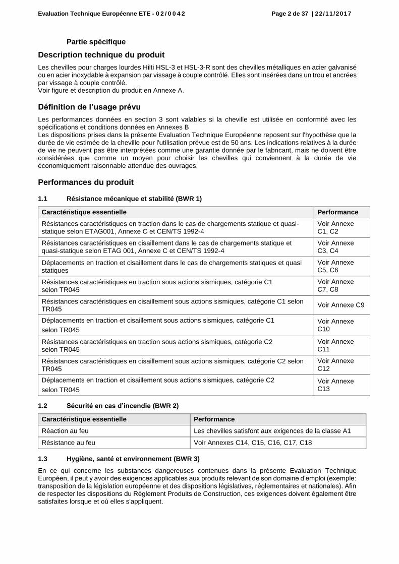
1.1 Résistance mécanique et stabilité (BWR 1)
Caractéristique essentielle Performance
Résistances caractéristiques en traction dans le cas de chargements statique et quasi-statique selon ETAG001, Annexe C et CEN/TS 1992-4
Voir Annexe C1, C2
Résistances caractéristiques en cisaillement dans le cas de chargements statique et quasi-statique selon ETAG 001, Annexe C et CEN/TS 1992-4
Voir Annexe C3, C4
Déplacements en traction et cisaillement dans le cas de chargements statiques et quasi statiques
Voir Annexe C5, C6
Résistances caractéristiques en traction sous actions sismiques, catégorie C1 selon TR045
Voir Annexe C7, C8
Résistances caractéristiques en cisaillement sous actions sismiques, catégorie C1 selon TR045
Voir Annexe C9
Déplacements en traction et cisaillement sous actions sismiques, catégorie C1
selon TR045
Voir Annexe C10
Résistances caractéristiques en traction sous actions sismiques, catégorie C2 selon TR045
Voir Annexe C11
Résistances caractéristiques en cisaillement sous actions sismiques, catégorie C2 selon TR045
Voir Annexe C12
Déplacements en traction et cisaillement sous actions sismiques, catégorie C2
selon TR045
Voir Annexe C13
1.2 Sécurité en cas d’incendie (BWR 2)
Caractéristique essentielle Performance
Réaction au feu Les chevilles satisfont aux exigences de la classe A1
Résistance au feu Voir Annexes C14, C15, C16, C17, C18
1.3 Hygiène, santé et environnement (BWR 3)
En ce qui concerne les substances dangereuses contenues dans la présente Evaluation Technique Européen, il peut y avoir des exigences applicables aux produits relevant de son domaine d’emploi (exemple: transposition de la législation européenne et des dispositions législatives, réglementaires et nationales). Afin de respecter les dispositions du Règlement Produits de Construction, ces exigences doivent également être satisfaites lorsque et où elles s'appliquent.

Evaluation Technique Européenne ETE - 0 2 / 0 0 4 2
Page 3 de 37 | 22/11/2017
1.4 Sécurité d’utilisation (BWR 4)
Pour les exigences essentielles de Sécurité d’utilisation les mêmes critères que ceux mentionnés dans les exigences essentielles Résistance mécanique et stabilité sont applicables.
1.5 Protection contre le bruit (BWR 5)
Non applicable.
1.6 Economie d’énergie et isolation thermique (BWR 6)
Non applicable.
1.7 Utilisation durable des ressources naturelles (BWR 7)
Pour l'utilisation durable des ressources naturelles aucune performance n’a été déterminée pour ce produit.
1.8 Aspects généraux relatifs à l'aptitude à l’emploi
La durabilité et l’aptitude à l’usage ne sont assurées que si les spécifications pour l'usage prévu conformément à l'annexe B1 sont maintenues.
Evaluation et vérification de la constance des performances (AVCP)
Conformément à la décision 96/582/EC de la Commission Européenne1, tel que amendée, le système d’évaluation et de vérification de la constance des performances (Voir Annexe V du règlement n° 305/2011 du parlement Européen) donné dans le tableau suivant s’applique.
Produit Usage prévu Niveau ou Classe Système
Ancrages métalliques pour le béton
Pour fixer et / ou soutenir les éléments structurels en béton ou les éléments lourds comme l’habillage et les plafonds suspendus
― 1
Données techniques nécessaires pour la mise en place d’un système Evaluation et de vérification de la constance des performances (EVCP)
Les données techniques nécessaires à la mise en œuvre du système d’évaluation et de vérification de la constance des performances (EVCP) sont fixées dans le plan de contrôle déposé au Centre Scientifique et Technique du Bâtiment.
Le fabricant doit, sur la base d'un contrat, impliquer un organisme notifié pour les tâches visant la délivrance du certificat de conformité CE dans le domaine des fixations, basé sur ce plan de contrôle.
Délivré à Marne La Vallée le 22/11/2017 par
Charles Baloche
Directeur technique
1 Journal officiel des communautés Européennes L 254 du 08.10.1996
Evaluation Technique Européenne ETE - 0 2 / 0 0 4 2 Page 4 de 37 | 22/11/2017
Cheville Hilti pour charges lourdes HSL-3(-R)
Annexe A1
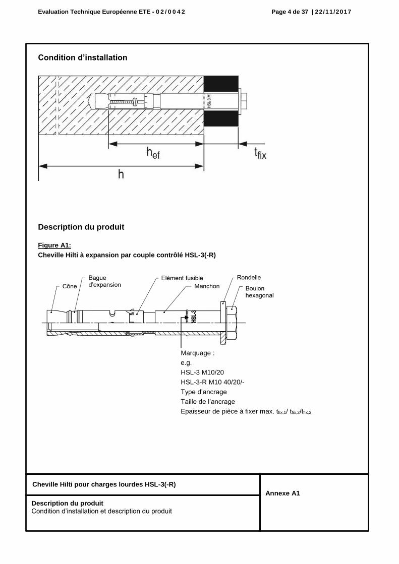
Condition d’installation
Description du produit
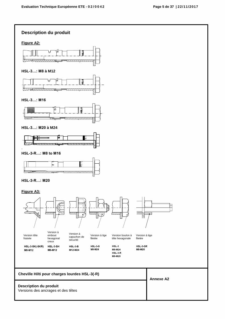
Figure A1:
Cheville Hilti à expansion par couple contrôlé HSL-3(-R)
Marquage :
e.g.
HSL-3 M10/20
HSL-3-R M10 40/20/-
Type d’ancrage
Taille de l’ancrage
Epaisseur de pièce à fixer max. tfix,1/ tfix,2/tfix,3
Description du produit Condition d’installation et description du produit
Evaluation Technique Européenne ETE - 0 2 / 0 0 4 2 Page 5 de 37 | 22/11/2017
Cheville Hilti pour charges lourdes HSL-3(-R)
Annexe A2
Description du produit
Figure A2:
HSL-3…: M8 à M12
HSL-3…: M16
HSL-3…: M20 à M24
.
HSL-3-R…: M8 to M16
HSL-3-R…: M20
Figure A3:
Version tête fraisée
Version à embout hexagonal creux
Version à capuchon de sécurité
Version à tige filetée
Version boulon à tête hexagonale
Version à tige filetée
Description du produit Versions des ancrages et des têtes
Evaluation Technique Européenne ETE - 0 2 / 0 0 4 2 Page 6 de 37 | 22/11/2017
Cheville Hilti pour charges lourdes HSL-3(-R)
Annexe A3
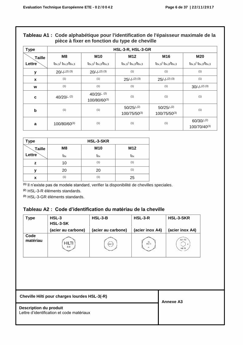
Tableau A1 : Code alphabétique pour l'identification de l'épaisseur maximale de la pièce à fixer en fonction du type de cheville
Type HSL-3-R, HSL-3-GR
Taille
Lettre
M8 M10 M12 M16 M20
tfix,1/ tfix,2/tfix,3 tfix,1/ tfix,2/tfix,3 tfix,1/ tfix,2/tfix,3 tfix,1/ tfix,2/tfix,3 tfix,1/ tfix,2/tfix,3
y 20/-/-(2) (3) 20/-/-(2) (3) (1) (1) (1)
x (1) (1) 25/-/-(2) (3) 25/-/-(2) (3) (1)
w (1) (1) (1) (1) 30/-/-(2) (3)
c 40/20/- (2) 40/20/- (2)
100/80/60(3) (1) (1) (1)
b (1) (1) 50/25/-(2)
100/75/50(3)
50/25/-(2)
100/75/50(3) (1)
a 100/80/60(3) (1) (1) (1) 60/30/-(2)
100/70/40(3)
Type HSL-3-SKR
Taille
Lettre
M8 M10 M12
tfix tfix tfix
z 10 (1) (1)
y 20 20 (1)
x (1) (1) 25
(1) Il n’existe pas de modele standard, verifier la disponibilité de chevilles speciales. (2) HSL-3-R éléments standards. (3) HSL-3-GR éléments standards.
Tableau A2 : Code d’identification du matériau de la cheville
Type HSL-3
HSL-3-SK
HSL-3-B HSL-3-R HSL-3-SKR
(acier au carbone) (acier au carbone) (acier inox A4) (acier inox A4)
Code matériau
Description du produit Lettre d’identification et code matériaux
Evaluation Technique Européenne ETE - 0 2 / 0 0 4 2 Page 7 de 37 | 22/11/2017
Cheville Hilti pour charges lourdes HSL-3(-R)
Annexe A4
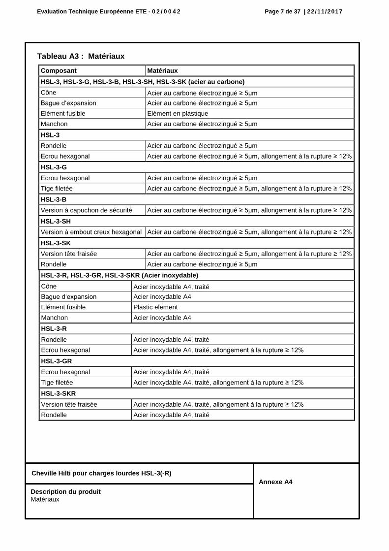
Tableau A3 : Matériaux
Composant Matériaux
HSL-3, HSL-3-G, HSL-3-B, HSL-3-SH, HSL-3-SK (acier au carbone)
Cône Acier au carbone électrozingué ≥ 5µm
Bague d‘expansion Acier au carbone électrozingué ≥ 5µm
Elément fusible Elément en plastique
Manchon Acier au carbone électrozingué ≥ 5µm
HSL-3
Rondelle Acier au carbone électrozingué ≥ 5µm
Ecrou hexagonal Acier au carbone électrozingué ≥ 5µm, allongement à la rupture ≥ 12%
HSL-3-G
Ecrou hexagonal Acier au carbone électrozingué ≥ 5µm
Tige filetée Acier au carbone électrozingué ≥ 5µm, allongement à la rupture ≥ 12%
HSL-3-B
Version à capuchon de sécurité Acier au carbone électrozingué ≥ 5µm, allongement à la rupture ≥ 12%
HSL-3-SH
Version à embout creux hexagonal Acier au carbone électrozingué ≥ 5µm, allongement à la rupture ≥ 12%
HSL-3-SK
Version tête fraisée Acier au carbone électrozingué ≥ 5µm, allongement à la rupture ≥ 12%
Rondelle Acier au carbone électrozingué ≥ 5µm
HSL-3-R, HSL-3-GR, HSL-3-SKR (Acier inoxydable)
Cône Acier inoxydable A4, traité
Bague d‘expansion Acier inoxydable A4
Elément fusible Plastic element
Manchon Acier inoxydable A4
HSL-3-R
Rondelle Acier inoxydable A4, traité
Ecrou hexagonal Acier inoxydable A4, traité, allongement à la rupture ≥ 12%
HSL-3-GR
Ecrou hexagonal Acier inoxydable A4, traité
Tige filetée Acier inoxydable A4, traité, allongement à la rupture ≥ 12%
HSL-3-SKR
Version tête fraisée Acier inoxydable A4, traité, allongement à la rupture ≥ 12%
Rondelle Acier inoxydable A4, traité
Description du produit Matériaux
Evaluation Technique Européenne ETE - 0 2 / 0 0 4 2 Page 8 de 37 | 22/11/2017
Cheville Hilti pour charges lourdes HSL-3(-R)
Annexe B1
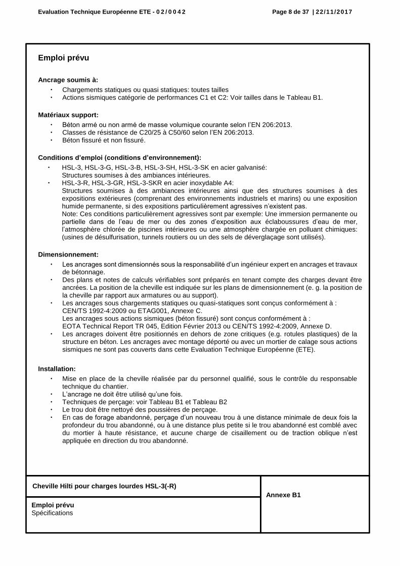
Emploi prévu
Ancrage soumis à:
Chargements statiques ou quasi statiques: toutes tailles Actions sismiques catégorie de performances C1 et C2: Voir tailles dans le Tableau B1.
Matériaux support:
Béton armé ou non armé de masse volumique courante selon l’EN 206:2013. Classes de résistance de C20/25 à C50/60 selon l’EN 206:2013. Béton fissuré et non fissuré.
Conditions d’emploi (conditions d’environnement):
HSL-3, HSL-3-G, HSL-3-B, HSL-3-SH, HSL-3-SK en acier galvanisé: Structures soumises à des ambiances intérieures.
HSL-3-R, HSL-3-GR, HSL-3-SKR en acier inoxydable A4: Structures soumises à des ambiances intérieures ainsi que des structures soumises à des expositions extérieures (comprenant des environnements industriels et marins) ou une exposition humide permanente, si des expositions particulièrement agressives n’existent pas. Note: Ces conditions particulièrement agressives sont par exemple: Une immersion permanente ou partielle dans de l’eau de mer ou des zones d’exposition aux éclaboussures d’eau de mer, l’atmosphère chlorée de piscines intérieures ou une atmosphère chargée en polluant chimiques: (usines de désulfurisation, tunnels routiers ou un des sels de déverglaçage sont utilisés).
Dimensionnement:
Les ancrages sont dimensionnés sous la responsabilité d’un ingénieur expert en ancrages et travaux de bétonnage.
Des plans et notes de calculs vérifiables sont préparés en tenant compte des charges devant être ancrées. La position de la cheville est indiquée sur les plans de dimensionnement (e. g. la position de la cheville par rapport aux armatures ou au support).
Les ancrages sous chargements statiques ou quasi-statiques sont conçus conformément à : CEN/TS 1992-4:2009 ou ETAG001, Annexe C. Les ancrages sous actions sismiques (béton fissuré) sont conçus conformément à : EOTA Technical Report TR 045, Edition Février 2013 ou CEN/TS 1992-4:2009, Annexe D.
Les ancrages doivent être positionnés en dehors de zone critiques (e.g. rotules plastiques) de la structure en béton. Les ancrages avec montage déporté ou avec un mortier de calage sous actions sismiques ne sont pas couverts dans cette Evaluation Technique Européenne (ETE).
Installation:
Mise en place de la cheville réalisée par du personnel qualifié, sous le contrôle du responsable technique du chantier.
L’ancrage ne doit être utilisé qu’une fois. Techniques de perçage: voir Tableau B1 et Tableau B2 Le trou doit être nettoyé des poussières de perçage. En cas de forage abandonné, perçage d’un nouveau trou à une distance minimale de deux fois la
profondeur du trou abandonné, ou à une distance plus petite si le trou abandonné est comblé avec du mortier à haute résistance, et aucune charge de cisaillement ou de traction oblique n’est appliquée en direction du trou abandonné.
Emploi prévu Spécifications
Evaluation Technique Européenne ETE - 0 2 / 0 0 4 2 Page 9 de 37 | 22/11/2017
Cheville Hilti pour charges lourdes HSL-3(-R)
Annexe B2
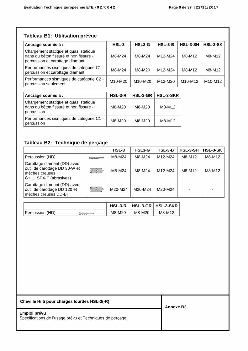
Tableau B1: Utilisation prévue
Ancrage soumis à : HSL-3 HSL3-G HSL-3-B HSL-3-SH HSL-3-SK
Chargement statique et quasi statique dans du béton fissuré et non fissuré - percussion et carottage diamant
M8-M24 M8-M24 M12-M24 M8-M12 M8-M12
Performances sismiques de catégorie C1 - percussion et carottage diamant
M8-M24 M8-M20 M12-M24 M8-M12 M8-M12
Performances sismiques de catégorie C2 - percussion seulement
M10-M20 M10-M20 M12-M20 M10-M12 M10-M12
Ancrage soumis à : HSL-3-R HSL-3-GR HSL-3-SKR
Chargement statique et quasi statique dans du béton fissuré et non fissuré - percussion
M8-M20 M8-M20 M8-M12
Performances sismiques de catégorie C1 - percussion
M8-M20 M8-M20 M8-M12
Tableau B2: Technique de perçage
HSL-3 HSL3-G HSL-3-B HSL-3-SH HSL-3-SK
Percussion (HD) M8-M24 M8-M24 M12-M24 M8-M12 M8-M12
Carottage diamant (DD) avec outil de carottage DD 30-W et mèches creuses C+ … SPX-T (abrasives)
M8-M24 M8-M24 M12-M24 M8-M12 M8-M12
Carottage diamant (DD) avec outil de carottage DD 120 et mèches creuses DD-BI
M20-M24 M20-M24 M20-M24 - -
HSL-3-R HSL-3-GR HSL-3-SKR
Percussion (HD) M8-M20 M8-M20 M8-M12
Emploi prévu Spécifications de l’usage prévu et Techniques de perçage
Evaluation Technique Européenne ETE - 0 2 / 0 0 4 2 Page 10 de 37 | 22/11/2017
Cheville Hilti pour charges lourdes HSL-3(-R)
Annexe B3
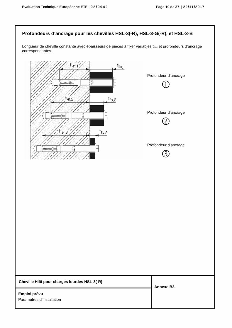
Profondeurs d’ancrage pour les chevilles HSL-3(-R), HSL-3-G(-R), et HSL-3-B
Longueur de cheville constante avec épaisseurs de pièces à fixer variables tfix,i et profondeurs d’ancrage correspondantes.
Profondeur d’ancrage
Profondeur d’ancrage
Profondeur d’ancrage
Emploi prévu
Paramètres d’installation
Evaluation Technique Européenne ETE - 0 2 / 0 0 4 2 Page 11 de 37 | 22/11/2017
Cheville Hilti pour charges lourdes HSL-3(-R)
Annexe B4
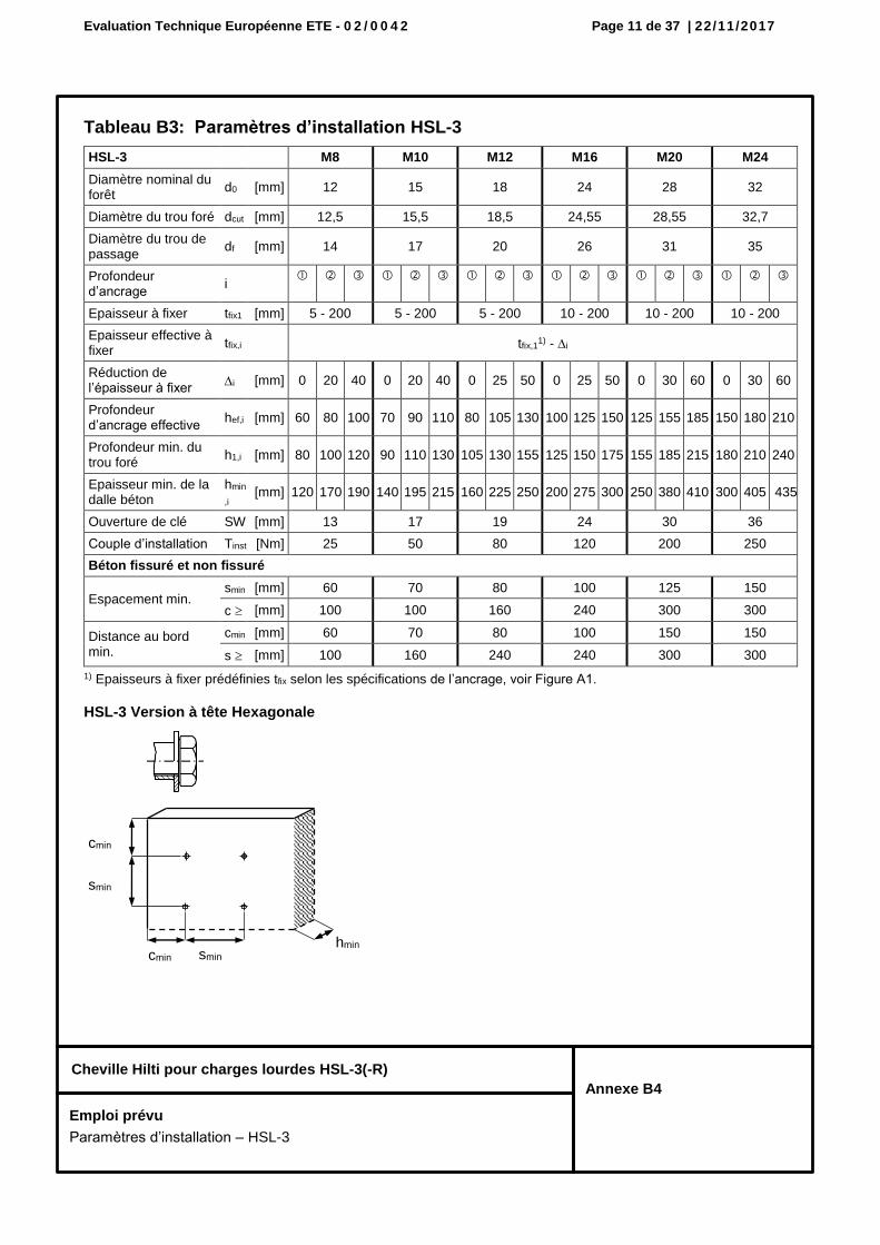
Tableau B3: Paramètres d’installation HSL-3
1) Epaisseurs à fixer prédéfinies tfix selon les spécifications de l’ancrage, voir Figure A1.
HSL-3 Version à tête Hexagonale
HSL-3 M8 M10 M12 M16 M20 M24
Diamètre nominal du forêt
d0 [mm] 12 15 18 24 28 32
Diamètre du trou foré dcut [mm] 12,5 15,5 18,5 24,55 28,55 32,7
Diamètre du trou de passage
df [mm] 14 17 20 26 31 35
Profondeur d’ancrage
i
Epaisseur à fixer tfix1 [mm] 5 - 200 5 - 200 5 - 200 10 - 200 10 - 200 10 - 200
Epaisseur effective à fixer
tfix,i tfix,11) - i
Réduction de l’épaisseur à fixer
i [mm] 0 20 40 0 20 40 0 25 50 0 25 50 0 30 60 0 30 60
Profondeur d’ancrage effective
hef,i [mm] 60 80 100 70 90 110 80 105 130 100 125 150 125 155 185 150 180 210
Profondeur min. du trou foré
h1,i [mm] 80 100 120 90 110 130 105 130 155 125 150 175 155 185 215 180 210 240
Epaisseur min. de la dalle béton
hmin
,i [mm] 120 170 190 140 195 215 160 225 250 200 275 300 250 380 410 300 405 435
Ouverture de clé SW [mm] 13 17 19 24 30 36
Couple d’installation Tinst [Nm] 25 50 80 120 200 250
Béton fissuré et non fissuré
Espacement min. smin [mm] 60 70 80 100 125 150
c [mm] 100 100 160 240 300 300
Distance au bord min.
cmin [mm] 60 70 80 100 150 150
s [mm] 100 160 240 240 300 300
cmin
cmin hmin
smin
smin
Emploi prévu
Paramètres d’installation – HSL-3
Evaluation Technique Européenne ETE - 0 2 / 0 0 4 2 Page 12 de 37 | 22/11/2017
Cheville Hilti pour charges lourdes HSL-3(-R)
Annexe B5
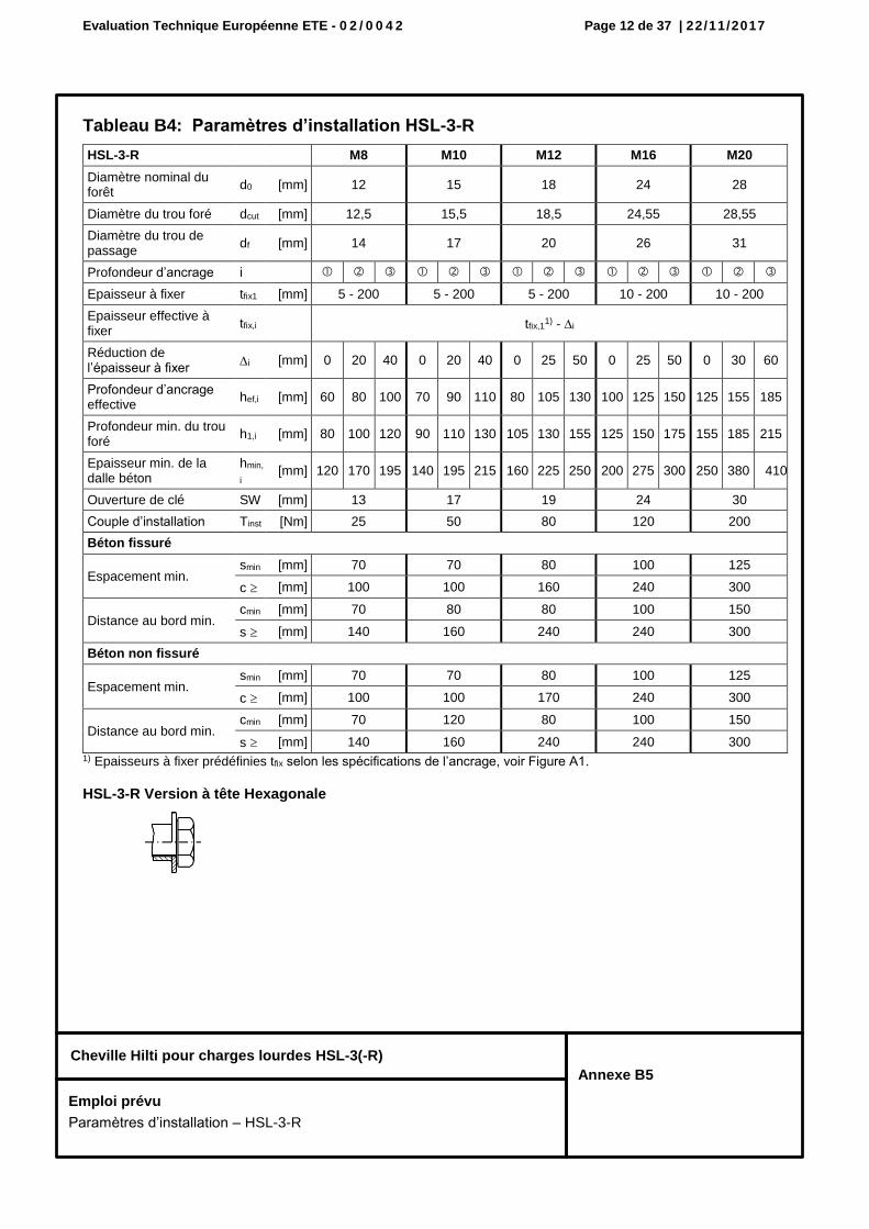
Tableau B4: Paramètres d’installation HSL-3-R
HSL-3-R M8 M10 M12 M16 M20
Diamètre nominal du forêt
d0 [mm] 12 15 18 24 28
Diamètre du trou foré dcut [mm] 12,5 15,5 18,5 24,55 28,55
Diamètre du trou de passage
df [mm] 14 17 20 26 31
Profondeur d’ancrage i
Epaisseur à fixer tfix1 [mm] 5 - 200 5 - 200 5 - 200 10 - 200 10 - 200
Epaisseur effective à fixer
tfix,i tfix,11) - i
Réduction de l’épaisseur à fixer
i [mm] 0 20 40 0 20 40 0 25 50 0 25 50 0 30 60
Profondeur d’ancrage effective
hef,i [mm] 60 80 100 70 90 110 80 105 130 100 125 150 125 155 185
Profondeur min. du trou foré
h1,i [mm] 80 100 120 90 110 130 105 130 155 125 150 175 155 185 215
Epaisseur min. de la dalle béton
hmin,
i [mm] 120 170 195 140 195 215 160 225 250 200 275 300 250 380 410
Ouverture de clé SW [mm] 13 17 19 24 30
Couple d’installation Tinst [Nm] 25 50 80 120 200
Béton fissuré
Espacement min. smin [mm] 70 70 80 100 125
c [mm] 100 100 160 240 300
Distance au bord min. cmin [mm] 70 80 80 100 150
s [mm] 140 160 240 240 300
Béton non fissuré
Espacement min. smin [mm] 70 70 80 100 125
c [mm] 100 100 170 240 300
Distance au bord min. cmin [mm] 70 120 80 100 150
s [mm] 140 160 240 240 300 1) Epaisseurs à fixer prédéfinies tfix selon les spécifications de l’ancrage, voir Figure A1.
HSL-3-R Version à tête Hexagonale
Emploi prévu
Paramètres d’installation – HSL-3-R
Evaluation Technique Européenne ETE - 0 2 / 0 0 4 2 Page 13 de 37 | 22/11/2017
Cheville Hilti pour charges lourdes HSL-3(-R)
Annexe B6
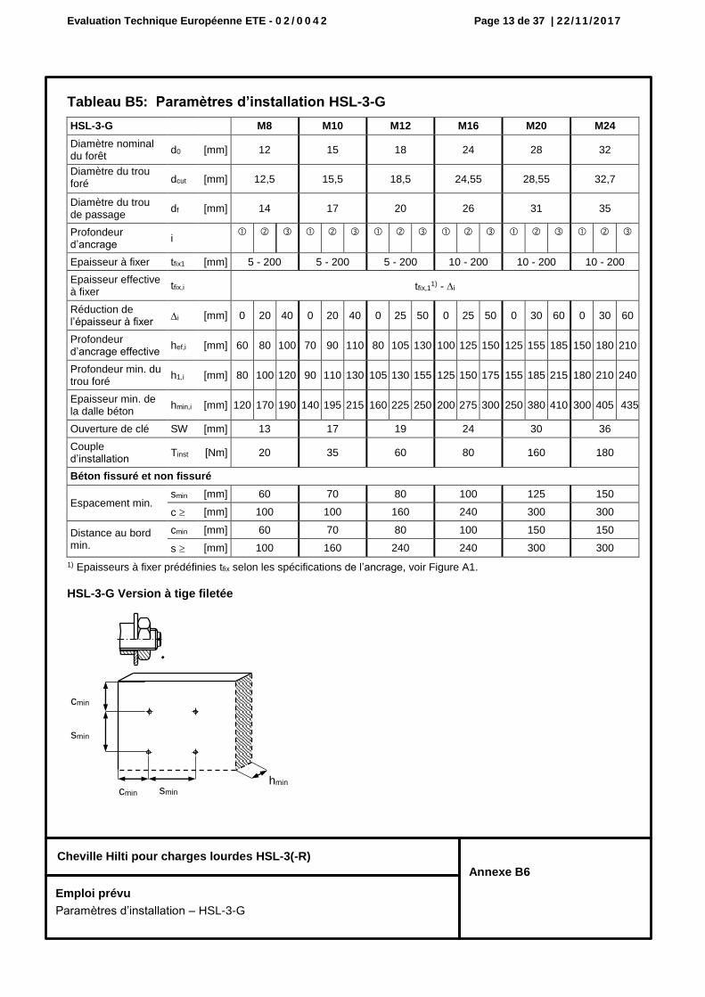
Tableau B5: Paramètres d’installation HSL-3-G
1) Epaisseurs à fixer prédéfinies tfix selon les spécifications de l’ancrage, voir Figure A1.
HSL-3-G Version à tige filetée
HSL-3-G M8 M10 M12 M16 M20 M24
Diamètre nominal du forêt
d0 [mm] 12 15 18 24 28 32
Diamètre du trou foré dcut [mm] 12,5 15,5 18,5 24,55 28,55 32,7
Diamètre du trou de passage
df [mm] 14 17 20 26 31 35
Profondeur d’ancrage
i
Epaisseur à fixer tfix1 [mm] 5 - 200 5 - 200 5 - 200 10 - 200 10 - 200 10 - 200
Epaisseur effective à fixer
tfix,i tfix,11) - i
Réduction de l’épaisseur à fixer
i [mm] 0 20 40 0 20 40 0 25 50 0 25 50 0 30 60 0 30 60
Profondeur d’ancrage effective
hef,i [mm] 60 80 100 70 90 110 80 105 130 100 125 150 125 155 185 150 180 210
Profondeur min. du trou foré
h1,i [mm] 80 100 120 90 110 130 105 130 155 125 150 175 155 185 215 180 210 240
Epaisseur min. de la dalle béton
hmin,i [mm] 120 170 190 140 195 215 160 225 250 200 275 300 250 380 410 300 405 435
Ouverture de clé SW [mm] 13 17 19 24 30 36
Couple d’installation
Tinst [Nm] 20 35 60 80 160 180
Béton fissuré et non fissuré
Espacement min. smin [mm] 60 70 80 100 125 150
c [mm] 100 100 160 240 300 300
Distance au bord min.
cmin [mm] 60 70 80 100 150 150
s [mm] 100 160 240 240 300 300
cmin
cmin hmin
smin
smin
Emploi prévu
Paramètres d’installation – HSL-3-G
G
Evaluation Technique Européenne ETE - 0 2 / 0 0 4 2 Page 14 de 37 | 22/11/2017
Cheville Hilti pour charges lourdes HSL-3(-R)
Annexe B7
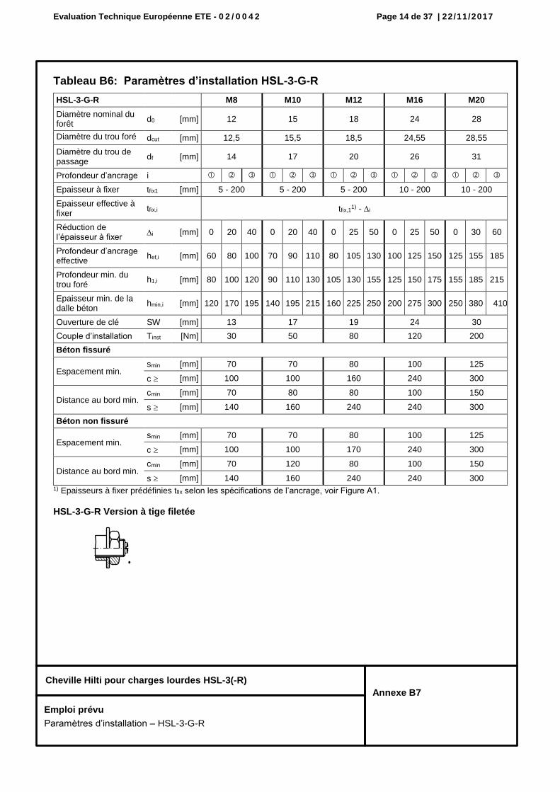
Tableau B6: Paramètres d’installation HSL-3-G-R
HSL-3-G-R M8 M10 M12 M16 M20
Diamètre nominal du forêt
d0 [mm] 12 15 18 24 28
Diamètre du trou foré dcut [mm] 12,5 15,5 18,5 24,55 28,55
Diamètre du trou de passage
df [mm] 14 17 20 26 31
Profondeur d’ancrage i
Epaisseur à fixer tfix1 [mm] 5 - 200 5 - 200 5 - 200 10 - 200 10 - 200
Epaisseur effective à fixer
tfix,i tfix,11) - i
Réduction de l’épaisseur à fixer
i [mm] 0 20 40 0 20 40 0 25 50 0 25 50 0 30 60
Profondeur d’ancrage effective
hef,i [mm] 60 80 100 70 90 110 80 105 130 100 125 150 125 155 185
Profondeur min. du trou foré
h1,i [mm] 80 100 120 90 110 130 105 130 155 125 150 175 155 185 215
Epaisseur min. de la dalle béton
hmin,i [mm] 120 170 195 140 195 215 160 225 250 200 275 300 250 380 410
Ouverture de clé SW [mm] 13 17 19 24 30
Couple d’installation Tinst [Nm] 30 50 80 120 200
Béton fissuré
Espacement min. smin [mm] 70 70 80 100 125
c [mm] 100 100 160 240 300
Distance au bord min. cmin [mm] 70 80 80 100 150
s [mm] 140 160 240 240 300
Béton non fissuré
Espacement min. smin [mm] 70 70 80 100 125
c [mm] 100 100 170 240 300
Distance au bord min. cmin [mm] 70 120 80 100 150
s [mm] 140 160 240 240 300 1) Epaisseurs à fixer prédéfinies tfix selon les spécifications de l’ancrage, voir Figure A1.
HSL-3-G-R Version à tige filetée
Emploi prévu
Paramètres d’installation – HSL-3-G-R
G
Evaluation Technique Européenne ETE - 0 2 / 0 0 4 2 Page 15 de 37 | 22/11/2017
Cheville Hilti pour charges lourdes HSL-3(-R)
Annexe B8
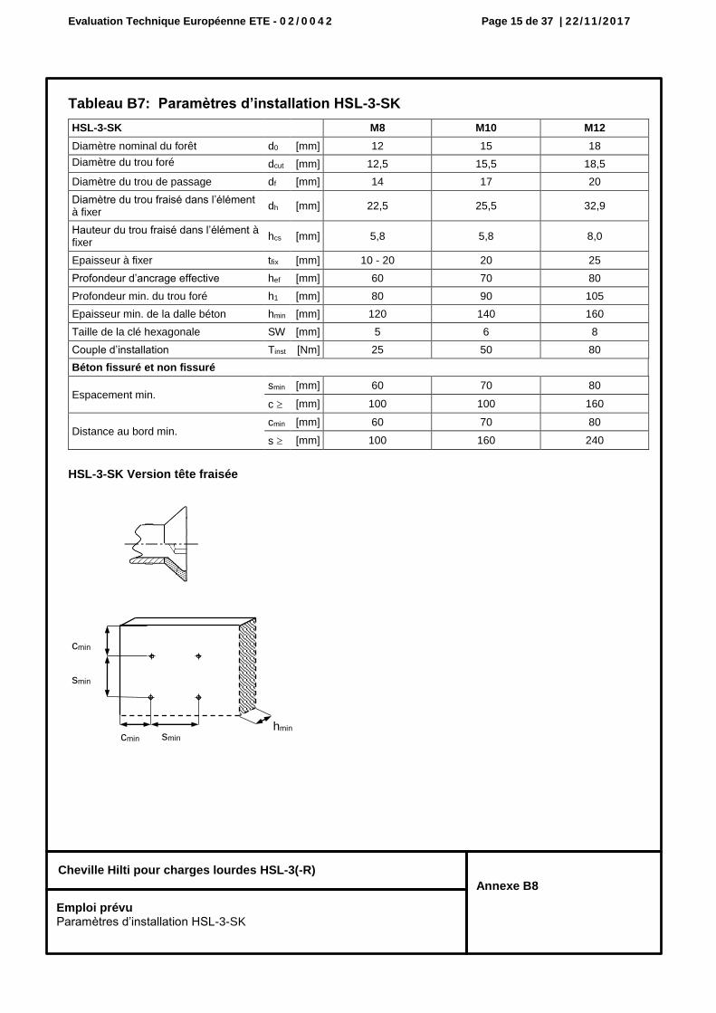
Tableau B7: Paramètres d’installation HSL-3-SK
HSL-3-SK Version tête fraisée
HSL-3-SK M8 M10 M12
Diamètre nominal du forêt d0 [mm] 12 15 18
Diamètre du trou foré dcut [mm] 12,5 15,5 18,5
Diamètre du trou de passage df [mm] 14 17 20
Diamètre du trou fraisé dans l’élément à fixer
dh [mm] 22,5 25,5 32,9
Hauteur du trou fraisé dans l’élément à fixer
hcs [mm] 5,8 5,8 8,0
Epaisseur à fixer tfix [mm] 10 - 20 20 25
Profondeur d’ancrage effective hef [mm] 60 70 80
Profondeur min. du trou foré h1 [mm] 80 90 105
Epaisseur min. de la dalle béton hmin [mm] 120 140 160
Taille de la clé hexagonale SW [mm] 5 6 8
Couple d’installation Tinst [Nm] 25 50 80
Béton fissuré et non fissuré
Espacement min. smin [mm] 60 70 80
c [mm] 100 100 160
Distance au bord min. cmin [mm] 60 70 80
s [mm] 100 160 240
cmin
cmin hmin
smin
smin
Emploi prévu Paramètres d’installation HSL-3-SK
Evaluation Technique Européenne ETE - 0 2 / 0 0 4 2 Page 16 de 37 | 22/11/2017
Cheville Hilti pour charges lourdes HSL-3(-R)
Annexe B9
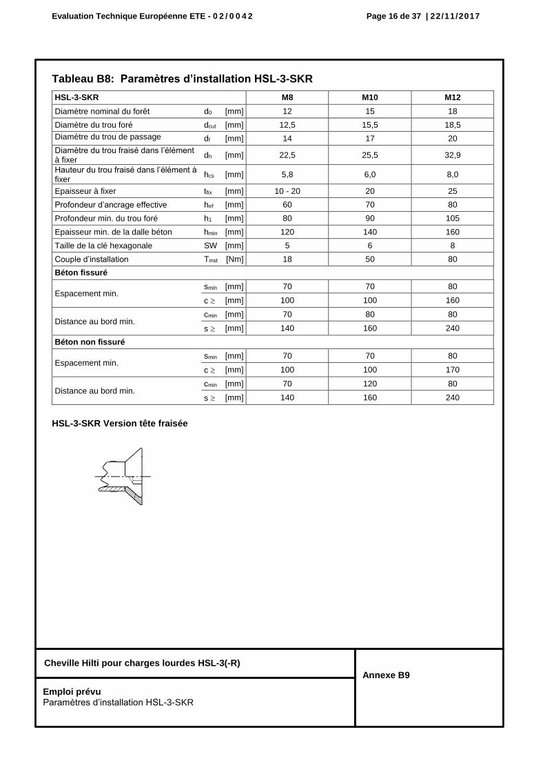
Tableau B8: Paramètres d’installation HSL-3-SKR
HSL-3-SKR Version tête fraisée
HSL-3-SKR M8 M10 M12
Diamètre nominal du forêt d0 [mm] 12 15 18
Diamètre du trou foré dcut [mm] 12,5 15,5 18,5
Diamètre du trou de passage df [mm] 14 17 20
Diamètre du trou fraisé dans l’élément à fixer
dh [mm] 22,5 25,5 32,9
Hauteur du trou fraisé dans l’élément à fixer
hcs [mm] 5,8 6,0 8,0
Epaisseur à fixer tfix [mm] 10 - 20 20 25
Profondeur d’ancrage effective hef [mm] 60 70 80
Profondeur min. du trou foré h1 [mm] 80 90 105
Epaisseur min. de la dalle béton hmin [mm] 120 140 160
Taille de la clé hexagonale SW [mm] 5 6 8
Couple d’installation Tinst [Nm] 18 50 80
Béton fissuré
Espacement min. smin [mm] 70 70 80
c [mm] 100 100 160
Distance au bord min. cmin [mm] 70 80 80
s [mm] 140 160 240
Béton non fissuré
Espacement min. smin [mm] 70 70 80
c [mm] 100 100 170
Distance au bord min. cmin [mm] 70 120 80
s [mm] 140 160 240
Emploi prévu Paramètres d’installation HSL-3-SKR
Evaluation Technique Européenne ETE - 0 2 / 0 0 4 2 Page 17 de 37 | 22/11/2017
Cheville Hilti pour charges lourdes HSL-3(-R)
Annexe B10
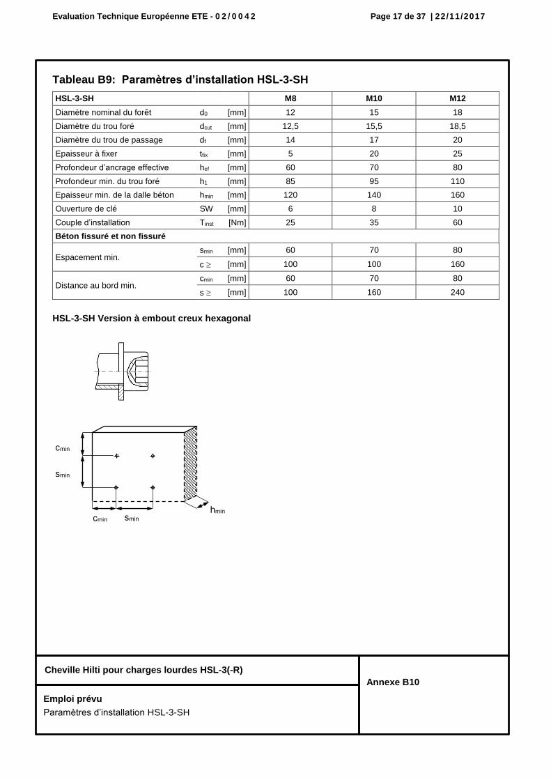
Tableau B9: Paramètres d’installation HSL-3-SH
HSL-3-SH Version à embout creux hexagonal
HSL-3-SH M8 M10 M12
Diamètre nominal du forêt d0 [mm] 12 15 18
Diamètre du trou foré dcut [mm] 12,5 15,5 18,5
Diamètre du trou de passage df [mm] 14 17 20
Epaisseur à fixer tfix [mm] 5 20 25
Profondeur d’ancrage effective hef [mm] 60 70 80
Profondeur min. du trou foré h1 [mm] 85 95 110
Epaisseur min. de la dalle béton hmin [mm] 120 140 160
Ouverture de clé SW [mm] 6 8 10
Couple d’installation Tinst [Nm] 25 35 60
Béton fissuré et non fissuré
Espacement min. smin [mm] 60 70 80
c [mm] 100 100 160
Distance au bord min. cmin [mm] 60 70 80
s [mm] 100 160 240
cmin
cmin hmin
smin
smin
Emploi prévu
Paramètres d’installation HSL-3-SH
Evaluation Technique Européenne ETE - 0 2 / 0 0 4 2 Page 18 de 37 | 22/11/2017
Cheville Hilti pour charges lourdes HSL-3(-R)
Annexe B11
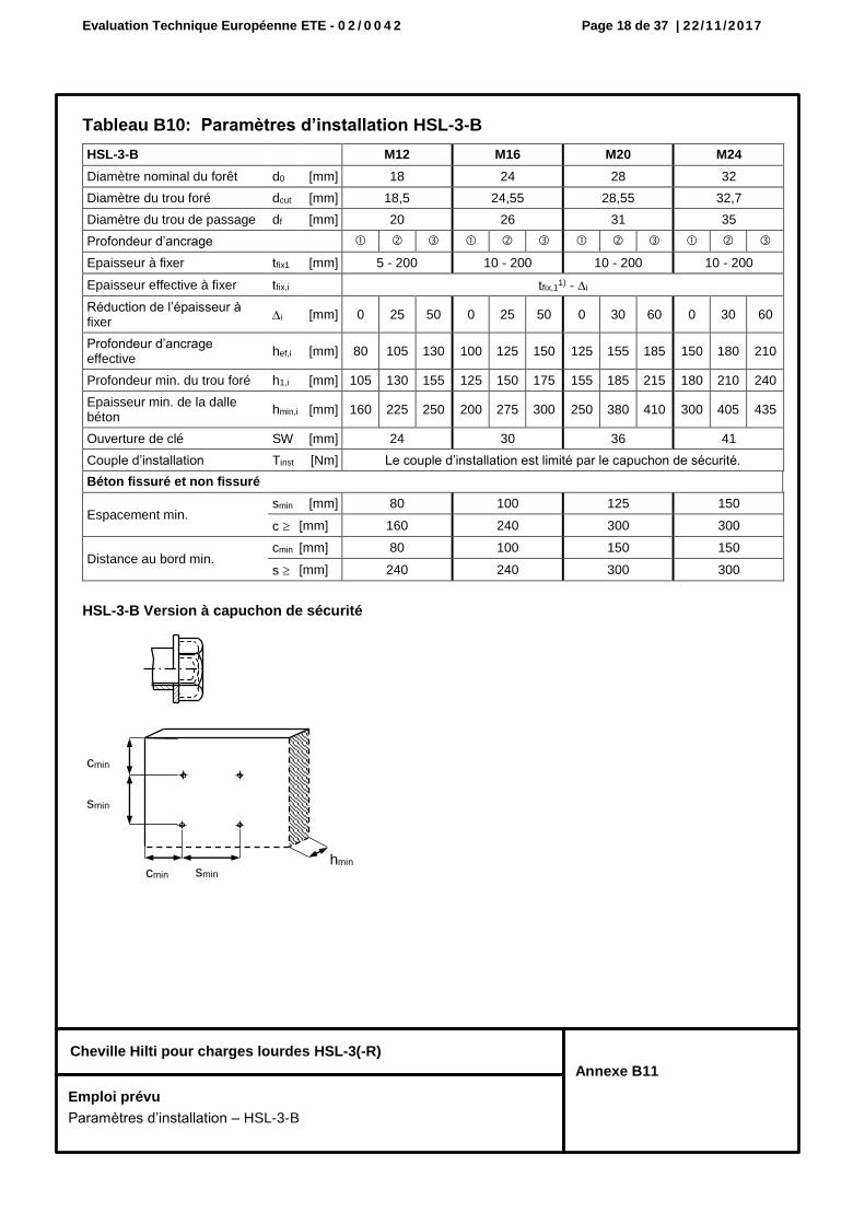
Tableau B10: Paramètres d’installation HSL-3-B
HSL-3-B Version à capuchon de sécurité
HSL-3-B M12 M16 M20 M24
Diamètre nominal du forêt d0 [mm] 18 24 28 32
Diamètre du trou foré dcut [mm] 18,5 24,55 28,55 32,7
Diamètre du trou de passage df [mm] 20 26 31 35
Profondeur d’ancrage
Epaisseur à fixer tfix1 [mm] 5 - 200 10 - 200 10 - 200 10 - 200
Epaisseur effective à fixer tfix,i tfix,11) - i
Réduction de l’épaisseur à fixer
i [mm] 0 25 50 0 25 50 0 30 60 0 30 60
Profondeur d’ancrage effective
hef,i [mm] 80 105 130 100 125 150 125 155 185 150 180 210
Profondeur min. du trou foré h1,i [mm] 105 130 155 125 150 175 155 185 215 180 210 240
Epaisseur min. de la dalle béton
hmin,i [mm] 160 225 250 200 275 300 250 380 410 300 405 435
Ouverture de clé SW [mm] 24 30 36 41
Couple d’installation Tinst [Nm] Le couple d’installation est limité par le capuchon de sécurité.
Béton fissuré et non fissuré
Espacement min. smin [mm] 80 100 125 150
c [mm] 160 240 300 300
Distance au bord min. cmin [mm] 80 100 150 150
s [mm] 240 240 300 300
cmin
cmin hmin
smin
smin
Emploi prévu
Paramètres d’installation – HSL-3-B
Evaluation Technique Européenne ETE - 0 2 / 0 0 4 2 Page 19 de 37 | 22/11/2017
Cheville Hilti pour charges lourdes HSL-3(-R)
Annexe B12
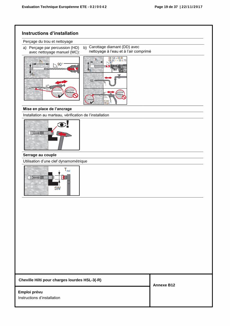
Instructions d’installation
Perçage du trou et nettoyage
a) Perçage par percussion (HD) avec nettoyage manuel (MC):
b) Carottage diamant (DD) avec nettoyage à l’eau et à l’air comprimé
Mise en place de l’ancrage
Installation au marteau, vérification de l’installation
Serrage au couple
Utilisation d’une clef dynamométrique
Emploi prévu
Instructions d’installation
Evaluation Technique Européenne ETE - 0 2 / 0 0 4 2 Page 20 de 37 | 22/11/2017
Cheville Hilti pour charges lourdes HSL-3(-R)
Annexe C1
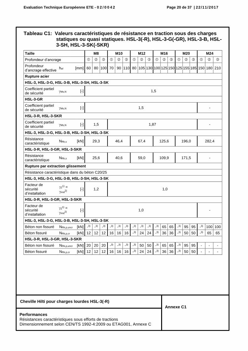
Tableau C1: Valeurs caractéristiques de résistance en traction sous des charges statiques ou quasi statiques. HSL-3(-R), HSL-3-G(-GR), HSL-3-B, HSL-3-SH, HSL-3-SK(-SKR)
Taille M8 M10 M12 M16 M20 M24
Profondeur d’ancrage
Profondeur d’ancrage effective
hef [mm] 60 80 100 70 90 110 80 105 130 100 125 150 125 155 185 150 180 210
Rupture acier
HSL-3, HSL-3-G, HSL-3-B, HSL-3-SH, HSL-3-SK
Coefficient partiel de sécurité
Ms,N [-] 1,5
HSL-3-GR
Coefficient partiel de sécurité
Ms,N [-] 1,5 -
HSL-3-R, HSL-3-SKR
Coefficient partiel de sécurité
Ms,N [-] 1,5 1,87 -
HSL-3, HSL-3-G, HSL-3-B, HSL-3-SH, HSL-3-SK
Résistance caractéristique
NRk,s [kN] 29,3 46,4 67,4 125,6 196,0 282,4
HSL-3-R, HSL-3-GR, HSL-3-SKR
Résistance caractéristique
NRk,s [kN] 25,6 40,6 59,0 109,9 171,5 -
Rupture par extraction glissement
Résistance caractéristique dans du béton C20/25
HSL-3, HSL-3-G, HSL-3-B, HSL-3-SH, HSL-3-SK
Facteur de sécurité d’installation
21) =
inst2)
[-] 1,2 1,0
HSL-3-R, HSL-3-GR, HSL-3-SKR
Facteur de sécurité d’installation
21) =
inst2)
[-] 1,0 -
HSL-3, HSL-3-G, HSL-3-B, HSL-3-SH, HSL-3-SK
Béton non fissuré NRk,p,uncr [kN] -3) -3) -3) -3) -3) -3) -3) -3) -3) -3) 65 65 -3) 95 95 -3) 100 100
Béton fissuré NRk,p,cr [kN] 12 12 12 16 16 16 -3) 24 24 -3) 36 36 -3) 50 50 -3) 65 65
HSL-3-R, HSL-3-GR, HSL-3-SKR
Béton non fissuré NRk,p,uncr [kN] 20 20 20 -3) -3) -3) -3) 50 50 -3) 65 65 -3) 95 95 - - -
Béton fissuré NRk,p,cr [kN] 12 12 12 16 16 16 -3) 24 24 -3) 36 36 -3) 50 50 - - -
Performances Résistances caractéristiques sous efforts de tractions Dimensionnement selon CEN/TS 1992-4:2009 ou ETAG001, Annexe C
Evaluation Technique Européenne ETE - 0 2 / 0 0 4 2 Page 21 de 37 | 22/11/2017
Cheville Hilti pour charges lourdes HSL-3(-R)
Annexe C2
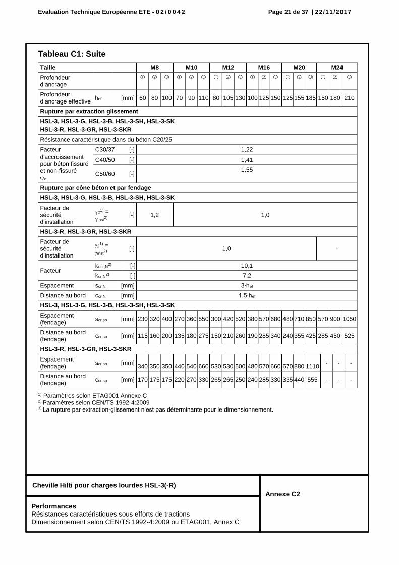
Tableau C1: Suite
1) Paramètres selon ETAG001 Annexe C 2) Paramètres selon CEN/TS 1992-4:2009 3) La rupture par extraction-glissement n’est pas déterminante pour le dimensionnement.
Taille M8 M10 M12 M16 M20 M24
Profondeur d’ancrage
Profondeur d’ancrage effective
hef [mm] 60 80 100 70 90 110 80 105 130 100 125 150 125 155 185 150 180 210
Rupture par extraction glissement
HSL-3, HSL-3-G, HSL-3-B, HSL-3-SH, HSL-3-SK
HSL-3-R, HSL-3-GR, HSL-3-SKR
Résistance caractéristique dans du béton C20/25
Facteur d'accroissement pour béton fissuré et non-fissuré
c
C30/37 [-] 1,22
C40/50 [-] 1,41
C50/60 [-] 1,55
Rupture par cône béton et par fendage
HSL-3, HSL-3-G, HSL-3-B, HSL-3-SH, HSL-3-SK
Facteur de sécurité d’installation
21) =
inst2)
[-] 1,2 1,0
HSL-3-R, HSL-3-GR, HSL-3-SKR
Facteur de sécurité d’installation
21) =
inst2)
[-] 1,0 -
Facteur kucr,N
2) [-] 10,1
kcr,N2) [-] 7,2
Espacement scr,N [mm] 3∙hef
Distance au bord ccr,N [mm] 1,5∙hef
HSL-3, HSL-3-G, HSL-3-B, HSL-3-SH, HSL-3-SK
Espacement (fendage)
scr,sp [mm] 230 320 400 270 360 550 300 420 520 380 570 680 480 710 850 570 900 1050
Distance au bord (fendage)
ccr,sp [mm] 115 160 200 135 180 275 150 210 260 190 285 340 240 355 425 285 450 525
HSL-3-R, HSL-3-GR, HSL-3-SKR
Espacement (fendage)
scr,sp [mm] 340 350 350 440 540 660 530 530 500 480 570 660 670 880 1110
- - -
Distance au bord (fendage)
ccr,sp [mm] 170 175 175 220 270 330 265 265 250 240 285 330 335 440 555 - - -
Performances Résistances caractéristiques sous efforts de tractions Dimensionnement selon CEN/TS 1992-4:2009 ou ETAG001, Annex C
Evaluation Technique Européenne ETE - 0 2 / 0 0 4 2 Page 22 de 37 | 22/11/2017
Cheville Hilti pour charges lourdes HSL-3(-R)
Annexe C3
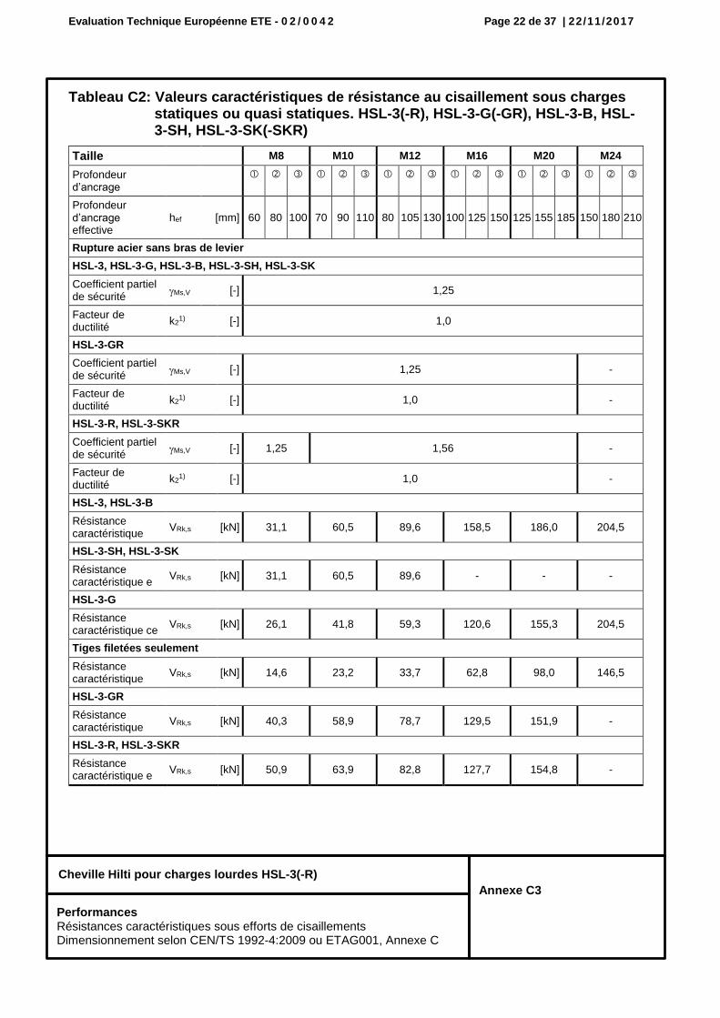
Tableau C2: Valeurs caractéristiques de résistance au cisaillement sous charges statiques ou quasi statiques. HSL-3(-R), HSL-3-G(-GR), HSL-3-B, HSL-3-SH, HSL-3-SK(-SKR)
Taille M8 M10 M12 M16 M20 M24
Profondeur d’ancrage
Profondeur d’ancrage effective
hef [mm] 60 80 100 70 90 110 80 105 130 100 125 150 125 155 185 150 180 210
Rupture acier sans bras de levier
HSL-3, HSL-3-G, HSL-3-B, HSL-3-SH, HSL-3-SK
Coefficient partiel de sécurité
Ms,V [-] 1,25
Facteur de ductilité
k21) [-] 1,0
HSL-3-GR
Coefficient partiel de sécurité
Ms,V [-] 1,25 -
Facteur de ductilité
k21) [-] 1,0 -
HSL-3-R, HSL-3-SKR
Coefficient partiel de sécurité
Ms,V [-] 1,25 1,56 -
Facteur de ductilité
k21) [-] 1,0 -
HSL-3, HSL-3-B
Résistance caractéristique
VRk,s [kN] 31,1 60,5 89,6 158,5 186,0 204,5
HSL-3-SH, HSL-3-SK
Résistance caractéristique e
VRk,s [kN] 31,1 60,5 89,6 - - -
HSL-3-G
Résistance caractéristique ce
VRk,s [kN] 26,1 41,8 59,3 120,6 155,3 204,5
Tiges filetées seulement
Résistance caractéristique
VRk,s [kN] 14,6 23,2 33,7 62,8 98,0 146,5
HSL-3-GR
Résistance caractéristique
VRk,s [kN] 40,3 58,9 78,7 129,5 151,9 -
HSL-3-R, HSL-3-SKR
Résistance caractéristique e
VRk,s [kN] 50,9 63,9 82,8 127,7 154,8 -
Performances Résistances caractéristiques sous efforts de cisaillements Dimensionnement selon CEN/TS 1992-4:2009 ou ETAG001, Annexe C
Evaluation Technique Européenne ETE - 0 2 / 0 0 4 2 Page 23 de 37 | 22/11/2017
Cheville Hilti pour charges lourdes HSL-3(-R)
Annexe C4
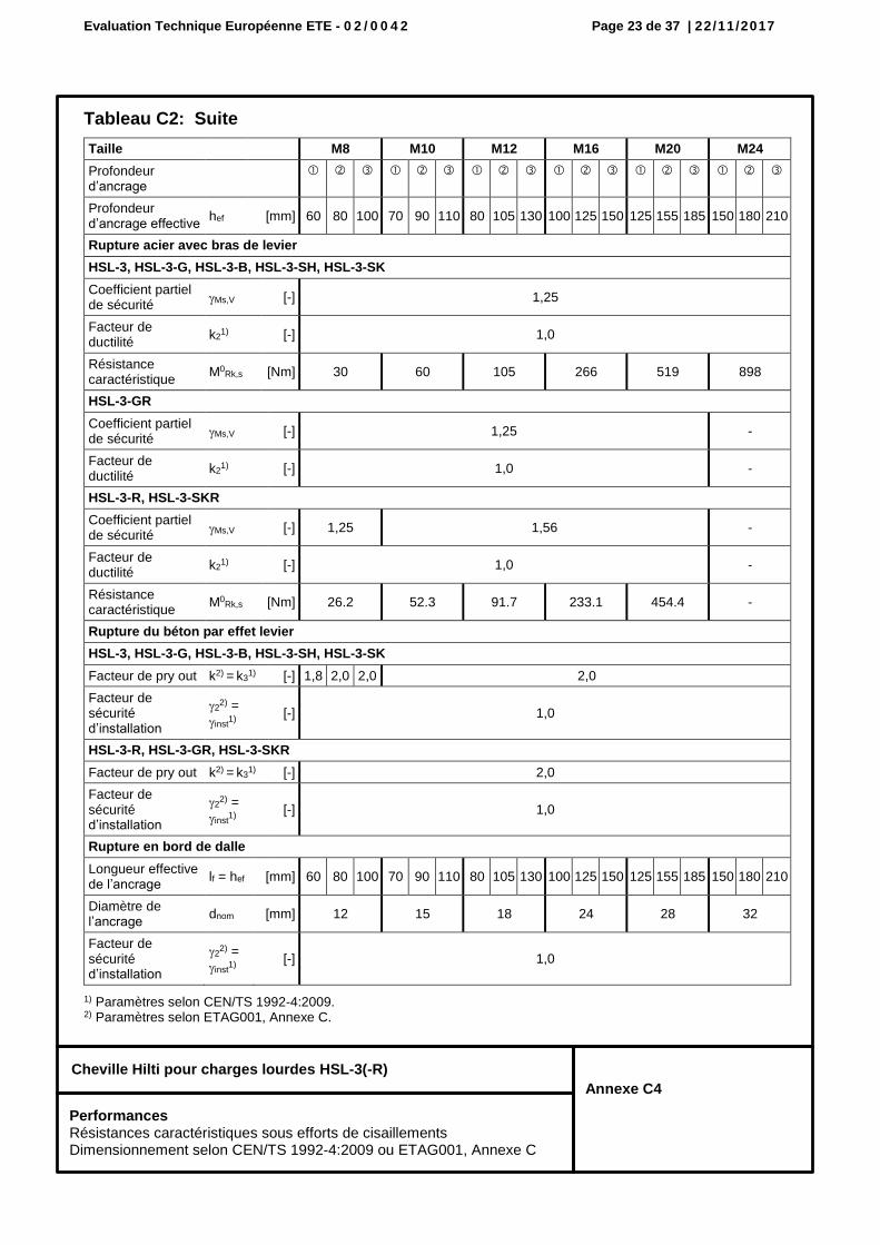
Tableau C2: Suite
1) Paramètres selon CEN/TS 1992-4:2009. 2) Paramètres selon ETAG001, Annexe C.
Taille M8 M10 M12 M16 M20 M24
Profondeur d’ancrage
Profondeur d’ancrage effective
hef [mm] 60 80 100 70 90 110 80 105 130 100 125 150 125 155 185 150 180 210
Rupture acier avec bras de levier
HSL-3, HSL-3-G, HSL-3-B, HSL-3-SH, HSL-3-SK
Coefficient partiel de sécurité
Ms,V [-] 1,25
Facteur de ductilité
k21) [-] 1,0
Résistance caractéristique
M0Rk,s [Nm] 30 60 105 266 519 898
HSL-3-GR
Coefficient partiel de sécurité
Ms,V [-] 1,25 -
Facteur de ductilité
k21) [-] 1,0 -
HSL-3-R, HSL-3-SKR
Coefficient partiel de sécurité
Ms,V [-] 1,25 1,56 -
Facteur de ductilité
k21) [-] 1,0 -
Résistance caractéristique
M0Rk,s [Nm] 26.2 52.3 91.7 233.1 454.4 -
Rupture du béton par effet levier
HSL-3, HSL-3-G, HSL-3-B, HSL-3-SH, HSL-3-SK
Facteur de pry out k2) = k3
1) [-] 1,8 2,0 2,0 2,0
Facteur de sécurité d’installation
22) =
inst1)
[-] 1,0
HSL-3-R, HSL-3-GR, HSL-3-SKR
Facteur de pry out k2) = k3
1) [-] 2,0
Facteur de sécurité d’installation
22) =
inst1)
[-] 1,0
Rupture en bord de dalle
Longueur effective de l’ancrage
lf = hef [mm] 60 80 100 70 90 110 80 105 130 100 125 150 125 155 185 150 180 210
Diamètre de l’ancrage
dnom [mm] 12 15 18 24 28 32
Facteur de sécurité d’installation
22) =
inst1)
[-] 1,0
Performances Résistances caractéristiques sous efforts de cisaillements Dimensionnement selon CEN/TS 1992-4:2009 ou ETAG001, Annexe C
Evaluation Technique Européenne ETE - 0 2 / 0 0 4 2 Page 24 de 37 | 22/11/2017
Cheville Hilti pour charges lourdes HSL-3(-R)
Annexe C5
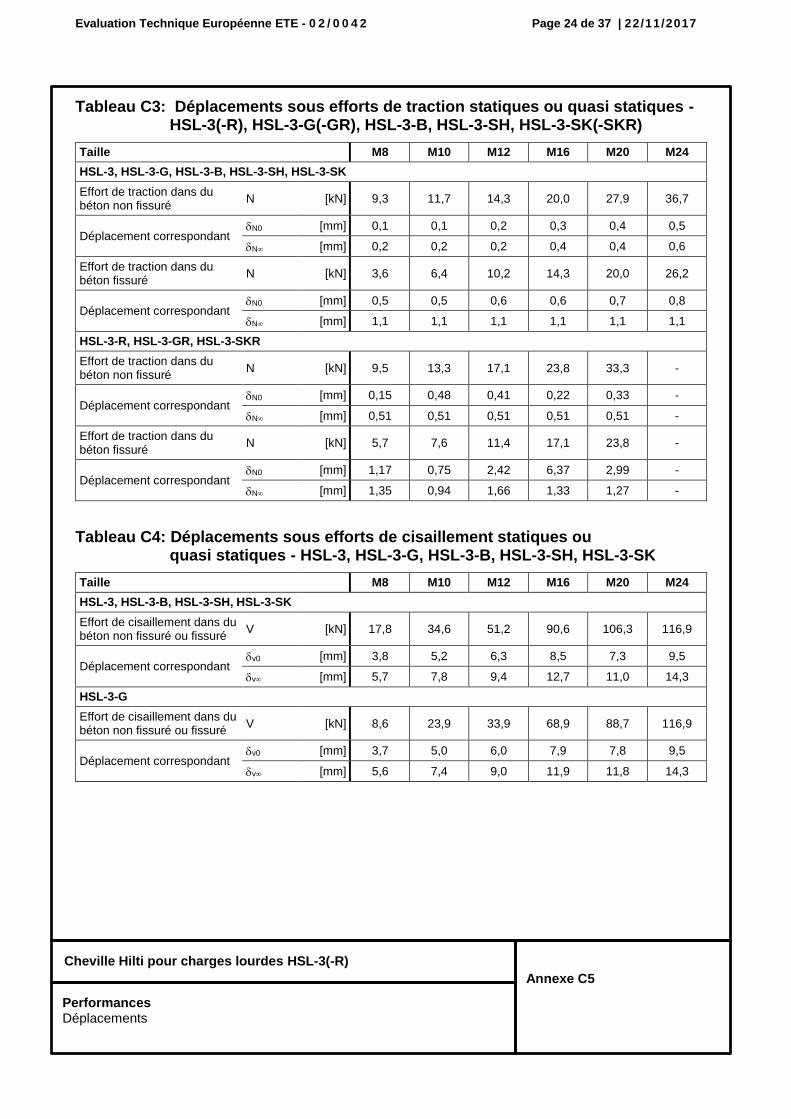
Tableau C3: Déplacements sous efforts de traction statiques ou quasi statiques - HSL-3(-R), HSL-3-G(-GR), HSL-3-B, HSL-3-SH, HSL-3-SK(-SKR)
Tableau C4: Déplacements sous efforts de cisaillement statiques ou quasi statiques - HSL-3, HSL-3-G, HSL-3-B, HSL-3-SH, HSL-3-SK
Taille M8 M10 M12 M16 M20 M24
HSL-3, HSL-3-G, HSL-3-B, HSL-3-SH, HSL-3-SK
Effort de traction dans du béton non fissuré
N [kN] 9,3 11,7 14,3 20,0 27,9 36,7
Déplacement correspondant N0 [mm] 0,1 0,1 0,2 0,3 0,4 0,5
N [mm] 0,2 0,2 0,2 0,4 0,4 0,6
Effort de traction dans du béton fissuré
N [kN] 3,6 6,4 10,2 14,3 20,0 26,2
Déplacement correspondant N0 [mm] 0,5 0,5 0,6 0,6 0,7 0,8
N [mm] 1,1 1,1 1,1 1,1 1,1 1,1
HSL-3-R, HSL-3-GR, HSL-3-SKR
Effort de traction dans du béton non fissuré
N [kN] 9,5 13,3 17,1 23,8 33,3 -
Déplacement correspondant N0 [mm] 0,15 0,48 0,41 0,22 0,33 -
N [mm] 0,51 0,51 0,51 0,51 0,51 -
Effort de traction dans du béton fissuré
N [kN] 5,7 7,6 11,4 17,1 23,8 -
Déplacement correspondant N0 [mm] 1,17 0,75 2,42 6,37 2,99 -
N [mm] 1,35 0,94 1,66 1,33 1,27 -
Taille M8 M10 M12 M16 M20 M24
HSL-3, HSL-3-B, HSL-3-SH, HSL-3-SK
Effort de cisaillement dans du béton non fissuré ou fissuré
V [kN] 17,8 34,6 51,2 90,6 106,3 116,9
Déplacement correspondant v0 [mm] 3,8 5,2 6,3 8,5 7,3 9,5
v [mm] 5,7 7,8 9,4 12,7 11,0 14,3
HSL-3-G
Effort de cisaillement dans du béton non fissuré ou fissuré
V [kN] 8,6 23,9 33,9 68,9 88,7 116,9
Déplacement correspondant v0 [mm] 3,7 5,0 6,0 7,9 7,8 9,5
v [mm] 5,6 7,4 9,0 11,9 11,8 14,3
Performances Déplacements
Evaluation Technique Européenne ETE - 0 2 / 0 0 4 2 Page 25 de 37 | 22/11/2017
Cheville Hilti pour charges lourdes HSL-3(-R)
Annexe C6
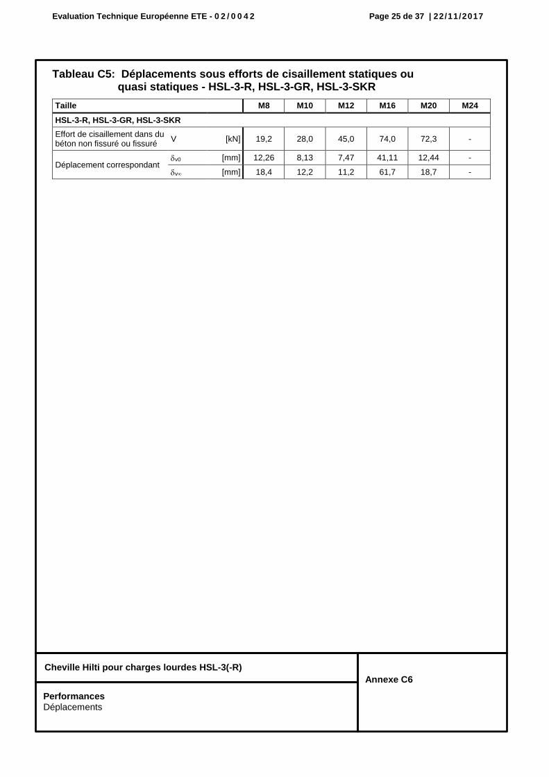
Tableau C5: Déplacements sous efforts de cisaillement statiques ou quasi statiques - HSL-3-R, HSL-3-GR, HSL-3-SKR
Taille M8 M10 M12 M16 M20 M24
HSL-3-R, HSL-3-GR, HSL-3-SKR
Effort de cisaillement dans du béton non fissuré ou fissuré
V [kN] 19,2 28,0 45,0 74,0 72,3 -
Déplacement correspondant v0 [mm] 12,26 8,13 7,47 41,11 12,44 -
v [mm] 18,4 12,2 11,2 61,7 18,7 -
Performances Déplacements
Evaluation Technique Européenne ETE - 0 2 / 0 0 4 2 Page 26 de 37 | 22/11/2017
Cheville Hilti pour charges lourdes HSL-3(-R)
Annexe C7
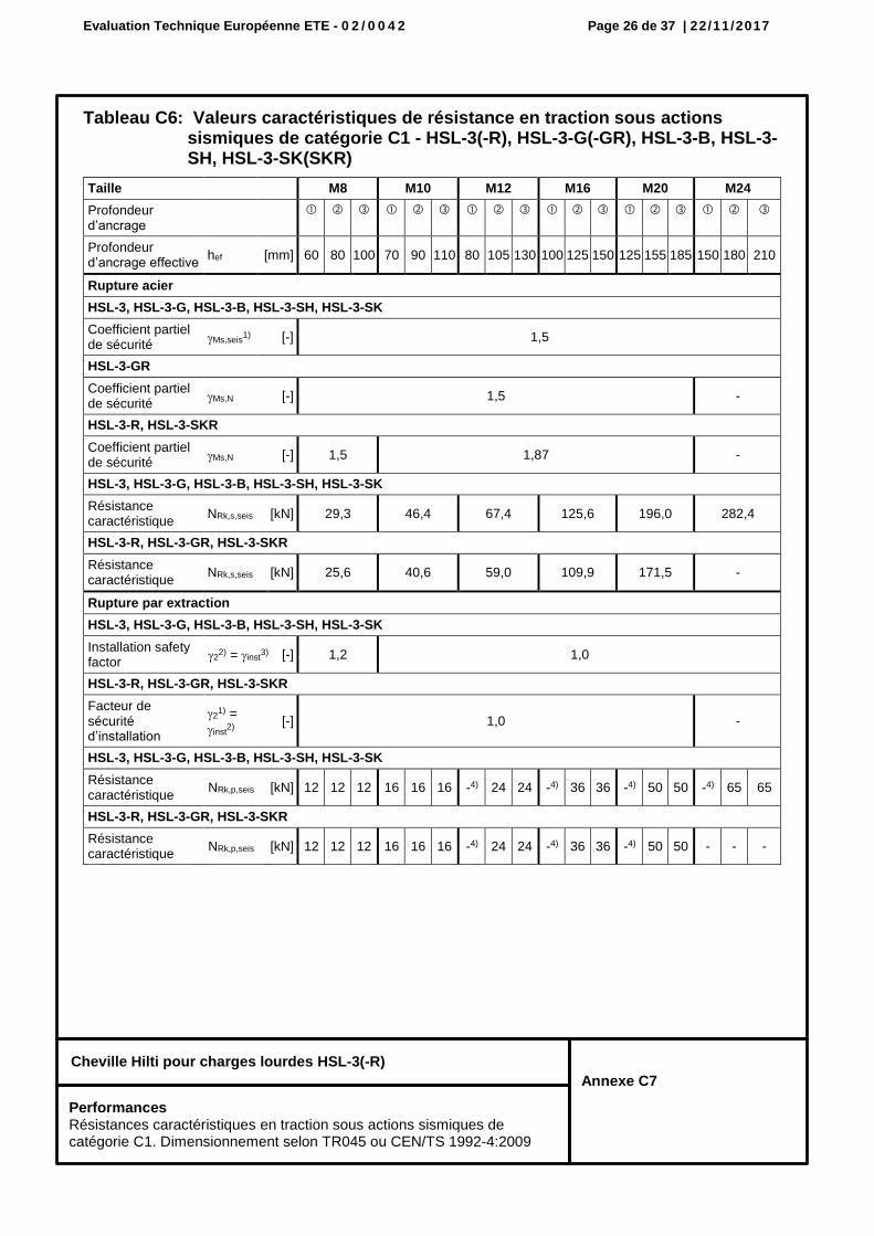
Tableau C6: Valeurs caractéristiques de résistance en traction sous actions sismiques de catégorie C1 - HSL-3(-R), HSL-3-G(-GR), HSL-3-B, HSL-3-SH, HSL-3-SK(SKR)
Taille M8 M10 M12 M16 M20 M24
Profondeur d’ancrage
Profondeur d’ancrage effective
hef [mm] 60 80 100 70 90 110 80 105 130 100 125 150 125 155 185 150 180 210
Rupture acier
HSL-3, HSL-3-G, HSL-3-B, HSL-3-SH, HSL-3-SK
Coefficient partiel de sécurité
Ms,seis1) [-] 1,5
HSL-3-GR
Coefficient partiel de sécurité
Ms,N [-] 1,5 -
HSL-3-R, HSL-3-SKR
Coefficient partiel de sécurité
Ms,N [-] 1,5 1,87 -
HSL-3, HSL-3-G, HSL-3-B, HSL-3-SH, HSL-3-SK
Résistance caractéristique
NRk,s,seis [kN] 29,3 46,4 67,4 125,6 196,0 282,4
HSL-3-R, HSL-3-GR, HSL-3-SKR
Résistance caractéristique
NRk,s,seis [kN] 25,6 40,6 59,0 109,9 171,5 -
Rupture par extraction
HSL-3, HSL-3-G, HSL-3-B, HSL-3-SH, HSL-3-SK
Installation safety factor
22) = inst
3) [-] 1,2 1,0
HSL-3-R, HSL-3-GR, HSL-3-SKR
Facteur de sécurité d’installation
21) =
inst2)
[-] 1,0 -
HSL-3, HSL-3-G, HSL-3-B, HSL-3-SH, HSL-3-SK
Résistance caractéristique
NRk,p,seis [kN] 12 12 12 16 16 16 -4) 24 24 -4) 36 36 -4) 50 50 -4) 65 65
HSL-3-R, HSL-3-GR, HSL-3-SKR
Résistance caractéristique
NRk,p,seis [kN] 12 12 12 16 16 16 -4) 24 24 -4) 36 36 -4) 50 50 - - -
Performances Résistances caractéristiques en traction sous actions sismiques de catégorie C1. Dimensionnement selon TR045 ou CEN/TS 1992-4:2009
Evaluation Technique Européenne ETE - 0 2 / 0 0 4 2 Page 27 de 37 | 22/11/2017
Cheville Hilti pour charges lourdes HSL-3(-R)
Annexe C8
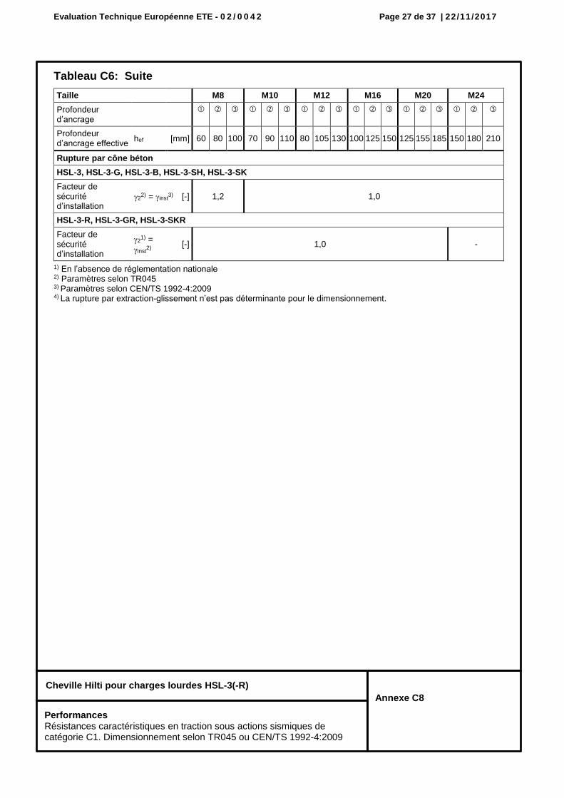
Tableau C6: Suite
1) En l’absence de réglementation nationale 2) Paramètres selon TR045 3) Paramètres selon CEN/TS 1992-4:2009 4) La rupture par extraction-glissement n’est pas déterminante pour le dimensionnement.
Taille M8 M10 M12 M16 M20 M24
Profondeur d’ancrage
Profondeur d’ancrage effective
hef [mm] 60 80 100 70 90 110 80 105 130 100 125 150 125 155 185 150 180 210
Rupture par cône béton
HSL-3, HSL-3-G, HSL-3-B, HSL-3-SH, HSL-3-SK
Facteur de sécurité d’installation
22) = inst
3) [-] 1,2 1,0
HSL-3-R, HSL-3-GR, HSL-3-SKR
Facteur de sécurité d’installation
21) =
inst2)
[-] 1,0 -
Performances Résistances caractéristiques en traction sous actions sismiques de catégorie C1. Dimensionnement selon TR045 ou CEN/TS 1992-4:2009
Evaluation Technique Européenne ETE - 0 2 / 0 0 4 2 Page 28 de 37 | 22/11/2017
Cheville Hilti pour charges lourdes HSL-3(-R)
Annexe C9
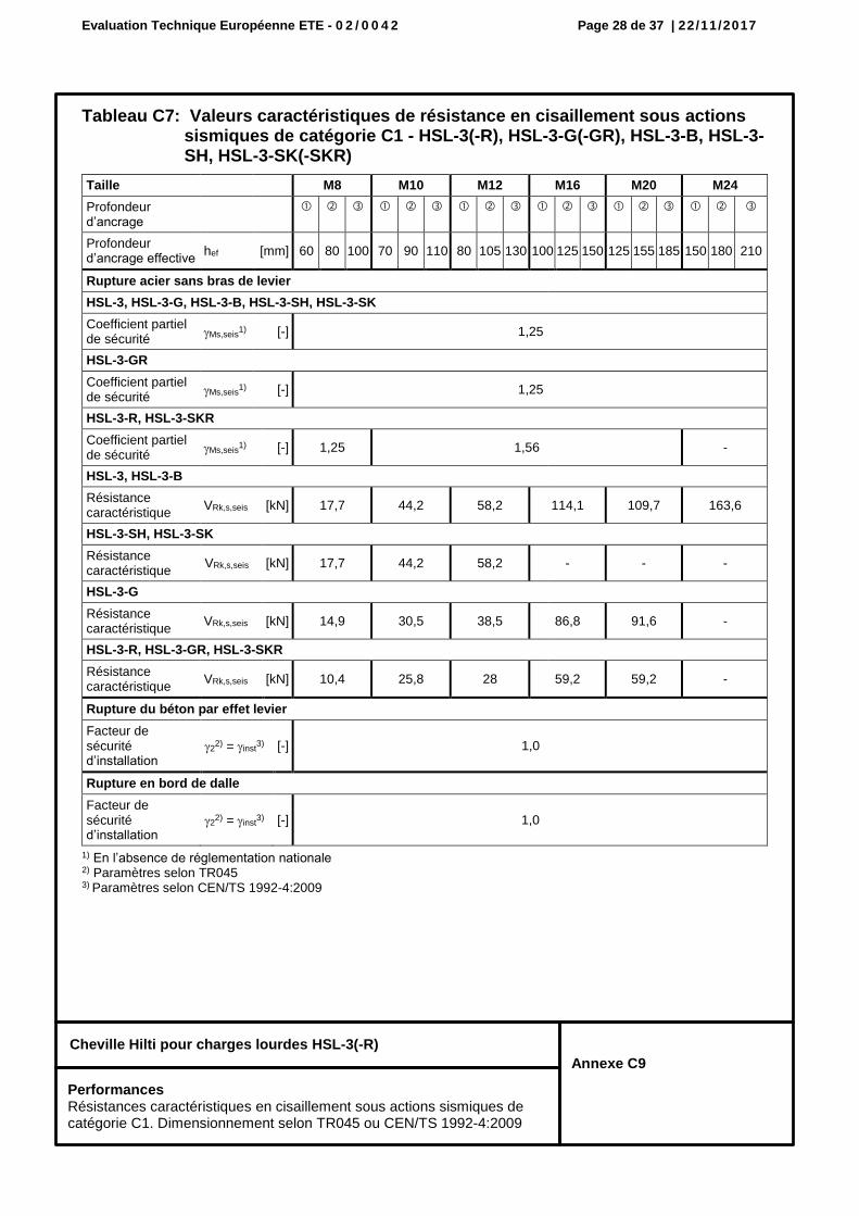
Tableau C7: Valeurs caractéristiques de résistance en cisaillement sous actions sismiques de catégorie C1 - HSL-3(-R), HSL-3-G(-GR), HSL-3-B, HSL-3-SH, HSL-3-SK(-SKR)
1) En l’absence de réglementation nationale 2) Paramètres selon TR045 3) Paramètres selon CEN/TS 1992-4:2009
Taille M8 M10 M12 M16 M20 M24
Profondeur d’ancrage
Profondeur d’ancrage effective
hef [mm] 60 80 100 70 90 110 80 105 130 100 125 150 125 155 185 150 180 210
Rupture acier sans bras de levier
HSL-3, HSL-3-G, HSL-3-B, HSL-3-SH, HSL-3-SK
Coefficient partiel de sécurité
Ms,seis1) [-] 1,25
HSL-3-GR
Coefficient partiel de sécurité
Ms,seis1) [-] 1,25
HSL-3-R, HSL-3-SKR
Coefficient partiel de sécurité
Ms,seis1) [-] 1,25 1,56 -
HSL-3, HSL-3-B
Résistance caractéristique
VRk,s,seis [kN] 17,7 44,2 58,2 114,1 109,7 163,6
HSL-3-SH, HSL-3-SK
Résistance caractéristique
VRk,s,seis [kN] 17,7 44,2 58,2 - - -
HSL-3-G
Résistance caractéristique
VRk,s,seis [kN] 14,9 30,5 38,5 86,8 91,6 -
HSL-3-R, HSL-3-GR, HSL-3-SKR
Résistance caractéristique
VRk,s,seis [kN] 10,4 25,8 28 59,2 59,2 -
Rupture du béton par effet levier
Facteur de sécurité d’installation
22) = inst
3) [-] 1,0
Rupture en bord de dalle
Facteur de sécurité d’installation
22) = inst
3) [-] 1,0
Performances Résistances caractéristiques en cisaillement sous actions sismiques de catégorie C1. Dimensionnement selon TR045 ou CEN/TS 1992-4:2009
Evaluation Technique Européenne ETE - 0 2 / 0 0 4 2 Page 29 de 37 | 22/11/2017
Cheville Hilti pour charges lourdes HSL-3(-R)
Annexe C10
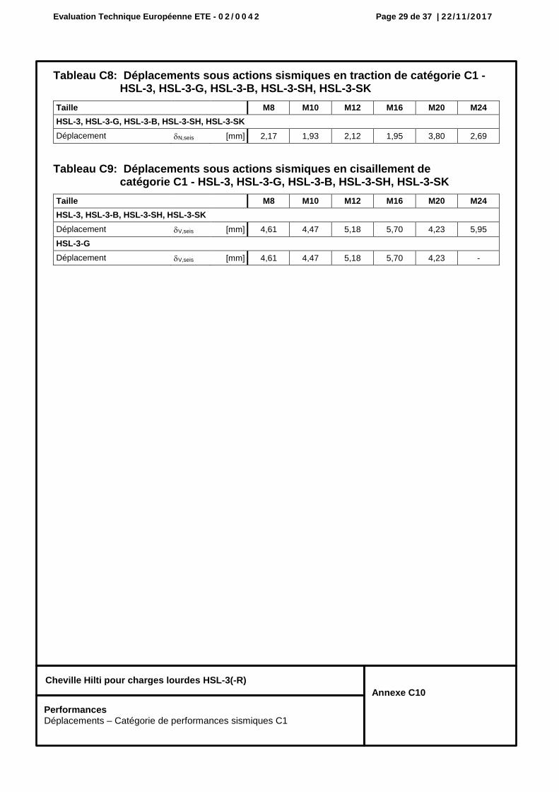
Tableau C8: Déplacements sous actions sismiques en traction de catégorie C1 - HSL-3, HSL-3-G, HSL-3-B, HSL-3-SH, HSL-3-SK
Tableau C9: Déplacements sous actions sismiques en cisaillement de catégorie C1 - HSL-3, HSL-3-G, HSL-3-B, HSL-3-SH, HSL-3-SK
Taille M8 M10 M12 M16 M20 M24
HSL-3, HSL-3-G, HSL-3-B, HSL-3-SH, HSL-3-SK
Déplacement N,seis [mm] 2,17 1,93 2,12 1,95 3,80 2,69
Taille M8 M10 M12 M16 M20 M24
HSL-3, HSL-3-B, HSL-3-SH, HSL-3-SK
Déplacement V,seis [mm] 4,61 4,47 5,18 5,70 4,23 5,95
HSL-3-G
Déplacement V,seis [mm] 4,61 4,47 5,18 5,70 4,23 -
Performances Déplacements – Catégorie de performances sismiques C1
Evaluation Technique Européenne ETE - 0 2 / 0 0 4 2 Page 30 de 37 | 22/11/2017
Cheville Hilti pour charges lourdes HSL-3(-R)
Annexe C11
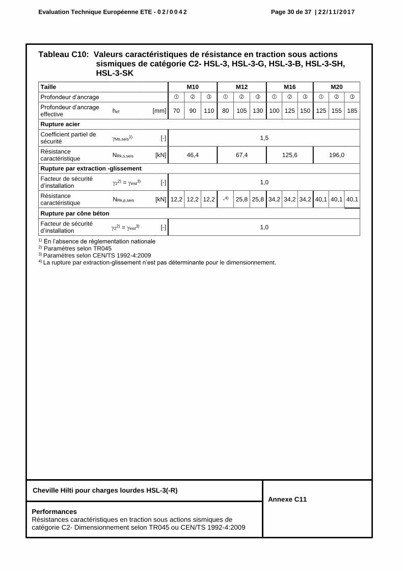
Tableau C10: Valeurs caractéristiques de résistance en traction sous actions sismiques de catégorie C2- HSL-3, HSL-3-G, HSL-3-B, HSL-3-SH, HSL-3-SK
1) En l’absence de réglementation nationale 2) Paramètres selon TR045 3) Paramètres selon CEN/TS 1992-4:2009 4) La rupture par extraction-glissement n’est pas déterminante pour le dimensionnement.
Taille M10 M12 M16 M20
Profondeur d’ancrage
Profondeur d’ancrage effective
hef [mm] 70 90 110 80 105 130 100 125 150 125 155 185
Rupture acier
Coefficient partiel de sécurité
Ms,seis1) [-] 1,5
Résistance caractéristique
NRk,s,seis [kN] 46,4 67,4 125,6 196,0
Rupture par extraction -glissement
Facteur de sécurité d’installation
22) = inst
3) [-] 1,0
Résistance caractéristique
NRk,p,seis [kN] 12,2 12,2 12,2 -4) 25,8 25,8 34,2 34,2 34,2 40,1 40,1 40,1
Rupture par cône béton
Facteur de sécurité d’installation
22) = inst
3) [-] 1,0
Performances Résistances caractéristiques en traction sous actions sismiques de catégorie C2- Dimensionnement selon TR045 ou CEN/TS 1992-4:2009
Evaluation Technique Européenne ETE - 0 2 / 0 0 4 2 Page 31 de 37 | 22/11/2017
Cheville Hilti pour charges lourdes HSL-3(-R)
Annexe C12
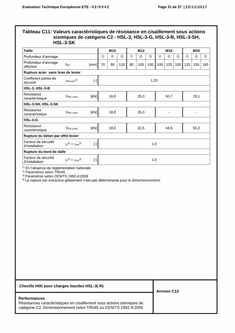
Tableau C11: Valeurs caractéristiques de résistance en cisaillement sous actions sismiques de catégorie C2 - HSL-3, HSL-3-G, HSL-3-B, HSL-3-SH, HSL-3-SK
1) En l’absence de réglementation nationale 2) Paramètres selon TR045 3) Paramètres selon CEN/TS 1992-4:2009 4) La rupture par extraction-glissement n’est pas déterminante pour le dimensionnement.
Taille M10 M12 M16 M20
Profondeur d’ancrage
Profondeur d’ancrage effective
hef [mm] 70 90 110 80 105 130 100 125 150 125 155 185
Rupture acier sans bras de levier
Coefficient partiel de sécurité
Ms,seis1) [-] 1,25
HSL-3, HSL-3-B
Résistance caractéristique
VRk,s,seis [kN] 18,8 26,3 50,7 78,1
HSL-3-SH, HSL-3-SK
Résistance caractéristique
VRk,s,seis [kN] 18,8 26,3 - -
HSL-3-G
Résistance caractéristique
VRk,s,seis [kN] 18,0 22,5 44,6 50,2
Rupture du béton par effet levier
Facteur de sécurité d’installation
22) = inst
3) [-] 1,0
Rupture du bord de dalle
Facteur de sécurité d’installation
22) = inst
3) [-] 1,0
Performances Résistances caractéristiques en cisaillement sous actions sismiques de catégorie C2. Dimensionnement selon TR045 ou CEN/TS 1992-4:2009
Evaluation Technique Européenne ETE - 0 2 / 0 0 4 2 Page 32 de 37 | 22/11/2017
Cheville Hilti pour charges lourdes HSL-3(-R)
Annexe C13
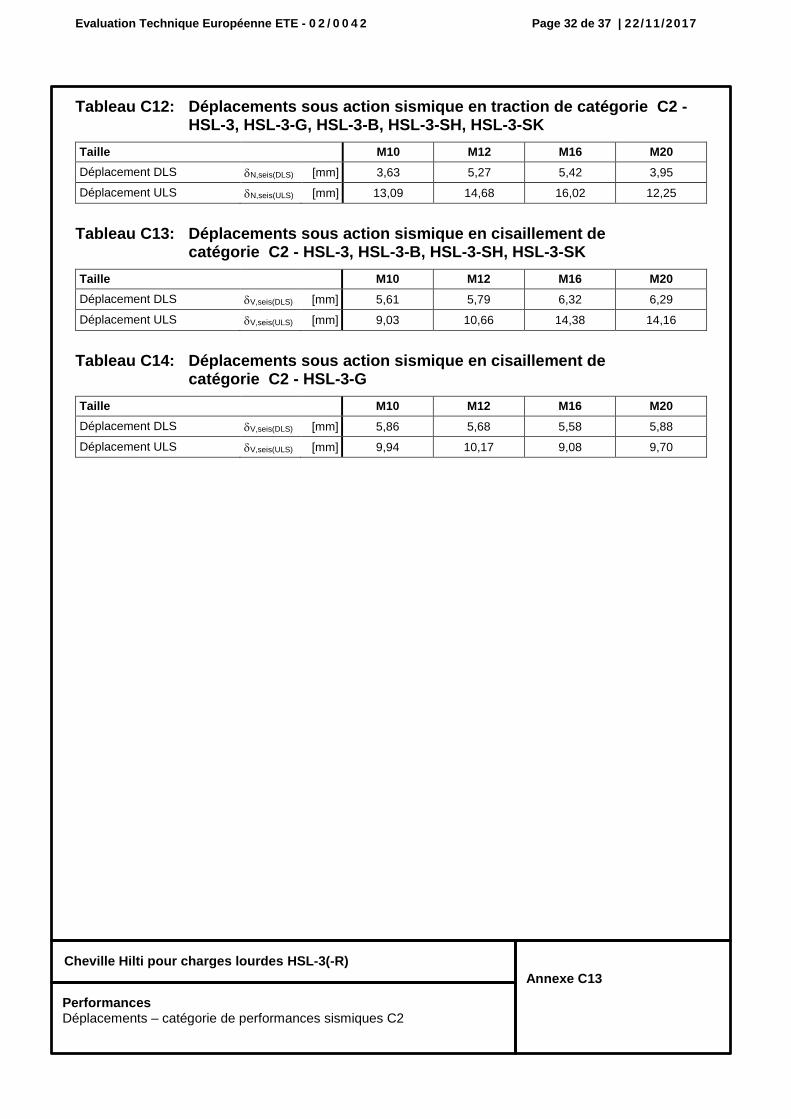
Tableau C12: Déplacements sous action sismique en traction de catégorie C2 - HSL-3, HSL-3-G, HSL-3-B, HSL-3-SH, HSL-3-SK
Taille M10 M12 M16 M20
Déplacement DLS N,seis(DLS) [mm] 3,63 5,27 5,42 3,95
Déplacement ULS N,seis(ULS) [mm] 13,09 14,68 16,02 12,25
Tableau C13: Déplacements sous action sismique en cisaillement de catégorie C2 - HSL-3, HSL-3-B, HSL-3-SH, HSL-3-SK
Taille M10 M12 M16 M20
Déplacement DLS V,seis(DLS) [mm] 5,61 5,79 6,32 6,29
Déplacement ULS V,seis(ULS) [mm] 9,03 10,66 14,38 14,16
Tableau C14: Déplacements sous action sismique en cisaillement de catégorie C2 - HSL-3-G
Taille M10 M12 M16 M20
Déplacement DLS V,seis(DLS) [mm] 5,86 5,68 5,58 5,88
Déplacement ULS V,seis(ULS) [mm] 9,94 10,17 9,08 9,70
Performances Déplacements – catégorie de performances sismiques C2
Evaluation Technique Européenne ETE - 0 2 / 0 0 4 2 Page 33 de 37 | 22/11/2017
Cheville Hilti pour charges lourdes HSL-3(-R)
Annexe C14
Performances Résistance caracteristique en traction sous exposition au feu
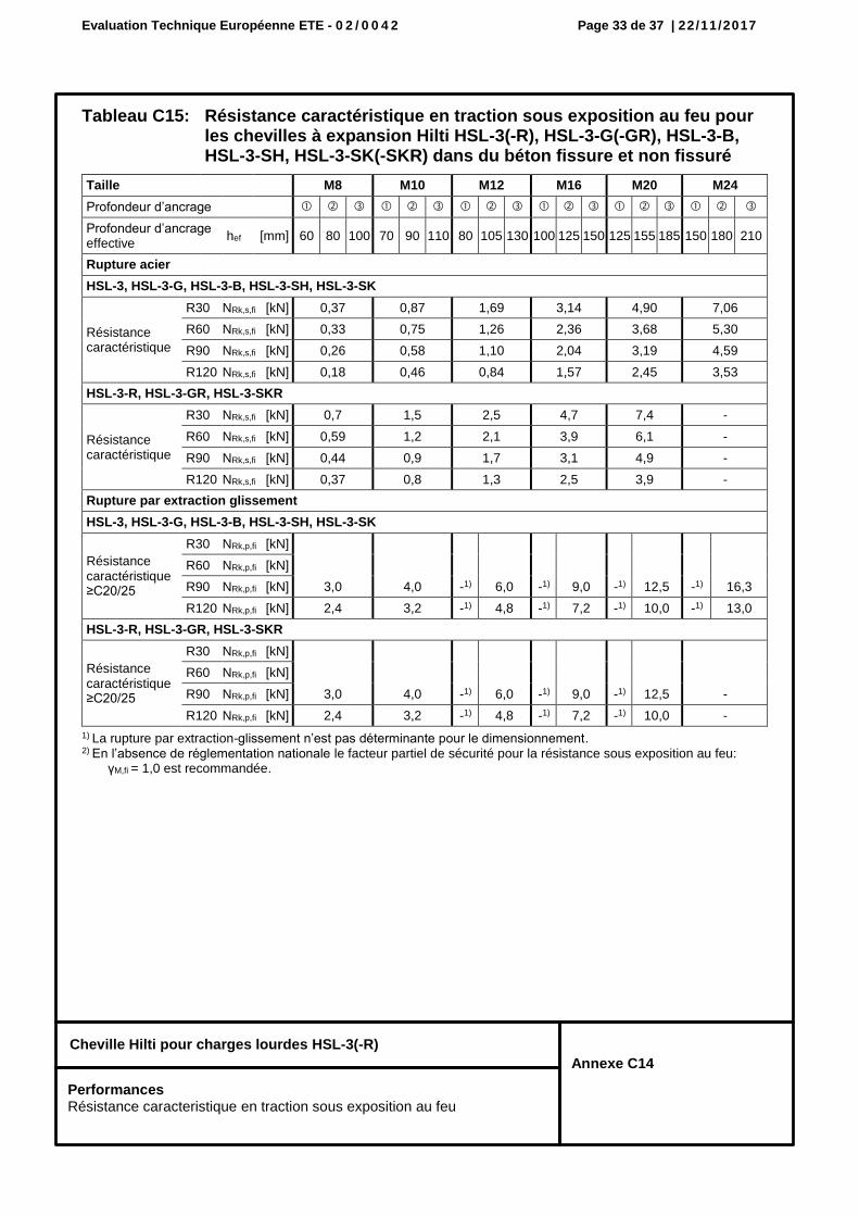
Tableau C15: Résistance caractéristique en traction sous exposition au feu pour les chevilles à expansion Hilti HSL-3(-R), HSL-3-G(-GR), HSL-3-B, HSL-3-SH, HSL-3-SK(-SKR) dans du béton fissure et non fissuré
1) La rupture par extraction-glissement n’est pas déterminante pour le dimensionnement. 2) En l’absence de réglementation nationale le facteur partiel de sécurité pour la résistance sous exposition au feu:
γM,fi = 1,0 est recommandée.
Taille M8 M10 M12 M16 M20 M24
Profondeur d’ancrage
Profondeur d’ancrage effective
hef [mm] 60 80 100 70 90 110 80 105 130 100 125 150 125 155 185 150 180 210
Rupture acier
HSL-3, HSL-3-G, HSL-3-B, HSL-3-SH, HSL-3-SK
Résistance caractéristique
R30 NRk,s,fi [kN] 0,37 0,87 1,69 3,14 4,90 7,06
R60 NRk,s,fi [kN] 0,33 0,75 1,26 2,36 3,68 5,30
R90 NRk,s,fi [kN] 0,26 0,58 1,10 2,04 3,19 4,59
R120 NRk,s,fi [kN] 0,18 0,46 0,84 1,57 2,45 3,53
HSL-3-R, HSL-3-GR, HSL-3-SKR
Résistance caractéristique
R30 NRk,s,fi [kN] 0,7 1,5 2,5 4,7 7,4 -
R60 NRk,s,fi [kN] 0,59 1,2 2,1 3,9 6,1 -
R90 NRk,s,fi [kN] 0,44 0,9 1,7 3,1 4,9 -
R120 NRk,s,fi [kN] 0,37 0,8 1,3 2,5 3,9 -
Rupture par extraction glissement
HSL-3, HSL-3-G, HSL-3-B, HSL-3-SH, HSL-3-SK
Résistance caractéristique ≥C20/25
R30 NRk,p,fi [kN]
3,0 4,0 -1) 6,0 -1) 9,0 -1) 12,5 -1) 16,3
R60 NRk,p,fi [kN]
R90 NRk,p,fi [kN]
R120 NRk,p,fi [kN] 2,4 3,2 -1) 4,8 -1) 7,2 -1) 10,0 -1) 13,0
HSL-3-R, HSL-3-GR, HSL-3-SKR
Résistance caractéristique ≥C20/25
R30 NRk,p,fi [kN]
3,0 4,0 -1) 6,0 -1) 9,0 -1) 12,5 -
R60 NRk,p,fi [kN]
R90 NRk,p,fi [kN]
R120 NRk,p,fi [kN] 2,4 3,2 -1) 4,8 -1) 7,2 -1) 10,0 -
Evaluation Technique Européenne ETE - 0 2 / 0 0 4 2 Page 34 de 37 | 22/11/2017
Cheville Hilti pour charges lourdes HSL-3(-R)
Annexe C15
Performances Résistance caracteristique en traction sous exposition au feu
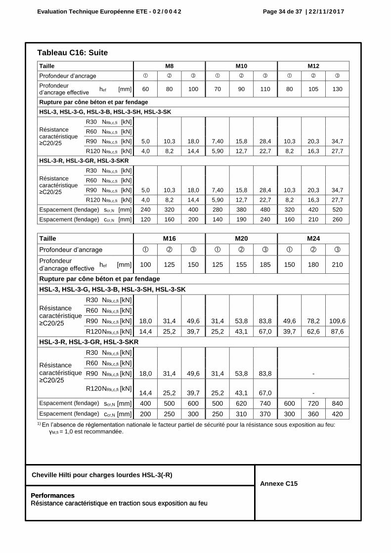
Tableau C16: Suite
1) En l’absence de réglementation nationale le facteur partiel de sécurité pour la résistance sous exposition au feu: γM,fi = 1,0 est recommandée.
Taille M8 M10 M12
Profondeur d’ancrage
Profondeur d’ancrage effective
hef [mm] 60 80 100 70 90 110 80 105 130
Rupture par cône béton et par fendage
HSL-3, HSL-3-G, HSL-3-B, HSL-3-SH, HSL-3-SK
Résistance caractéristique ≥C20/25
R30 NRk,c,fi [kN]
5,0 10,3 18,0 7,40 15,8 28,4 10,3 20,3 34,7
R60 NRk,c,fi [kN]
R90 NRk,c,fi [kN]
R120 NRk,c,fi [kN] 4,0 8,2 14,4 5,90 12,7 22,7 8,2 16,3 27,7
HSL-3-R, HSL-3-GR, HSL-3-SKR
Résistance caractéristique ≥C20/25
R30 NRk,c,fi [kN]
5,0 10,3 18,0 7,40 15,8 28,4 10,3 20,3 34,7
R60 NRk,c,fi [kN]
R90 NRk,c,fi [kN]
R120 NRk,c,fi [kN] 4,0 8,2 14,4 5,90 12,7 22,7 8,2 16,3 27,7
Espacement (fendage) scr,N [mm] 240 320 400 280 380 480 320 420 520
Espacement (fendage) ccr,N [mm] 120 160 200 140 190 240 160 210 260
Taille M16 M20 M24
Profondeur d’ancrage
Profondeur d’ancrage effective
hef [mm] 100 125 150 125 155 185 150 180 210
Rupture par cône béton et par fendage
HSL-3, HSL-3-G, HSL-3-B, HSL-3-SH, HSL-3-SK
Résistance caractéristique ≥C20/25
R30 NRk,c,fi [kN]
18,0 31,4 49,6 31,4 53,8 83,8 49,6 78,2 109,6
R60 NRk,c,fi [kN]
R90 NRk,c,fi [kN]
R120 NRk,c,fi [kN] 14,4 25,2 39,7 25,2 43,1 67,0 39,7 62,6 87,6
HSL-3-R, HSL-3-GR, HSL-3-SKR
Résistance caractéristique ≥C20/25
R30 NRk,c,fi [kN]
18,0 31,4 49,6 31,4 53,8 83,8
-
R60 NRk,c,fi [kN]
R90 NRk,c,fi [kN]
R120 NRk,c,fi [kN] 14,4 25,2 39,7 25,2 43,1 67,0
-
Espacement (fendage) scr,N [mm] 400 500 600 500 620 740 600 720 840
Espacement (fendage) ccr,N [mm] 200 250 300 250 310 370 300 360 420
Performances Résistance caractéristique en traction sous exposition au feu
Evaluation Technique Européenne ETE - 0 2 / 0 0 4 2 Page 35 de 37 | 22/11/2017
Cheville Hilti pour charges lourdes HSL-3(-R)
Annexe C16
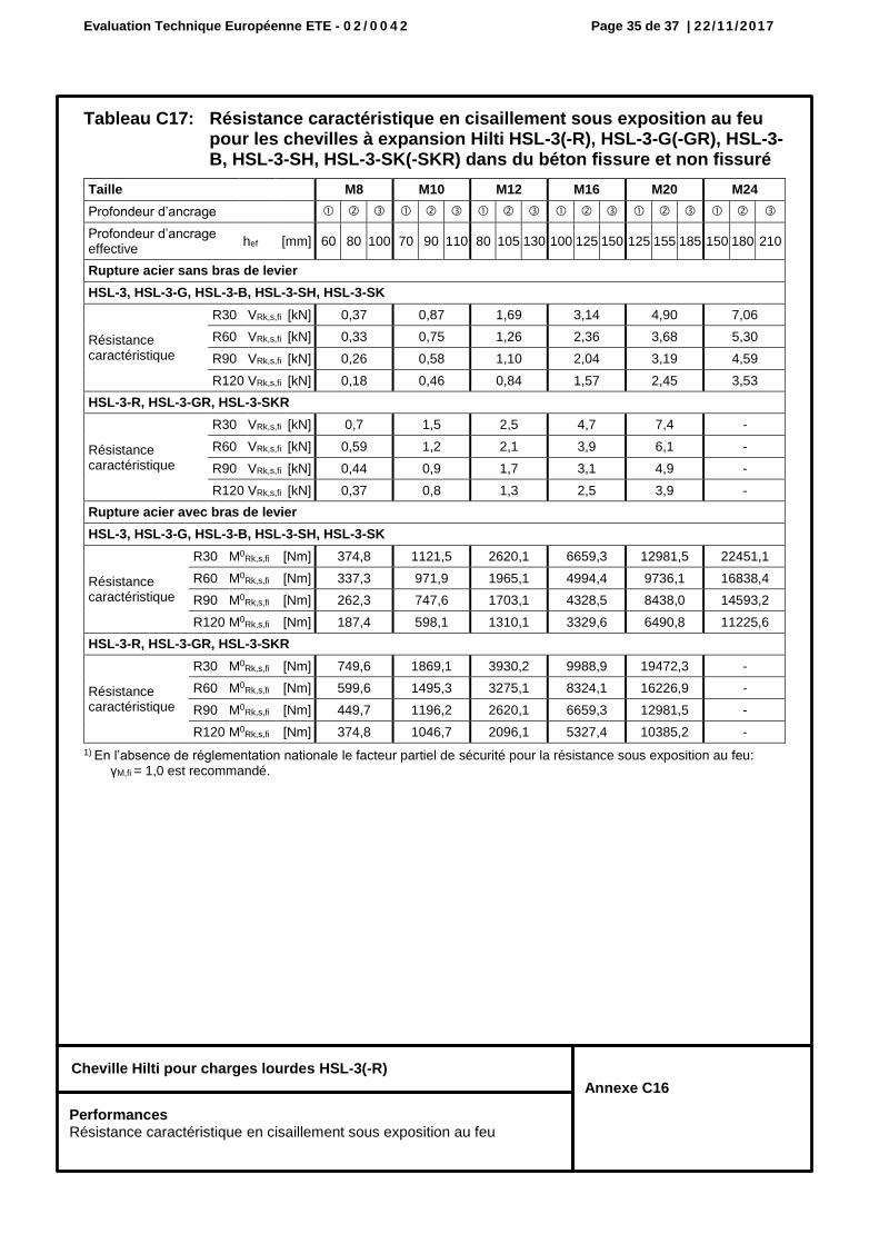
Performances Résistance caractéristique en cisaillement sous exposition au feu
Tableau C17: Résistance caractéristique en cisaillement sous exposition au feu pour les chevilles à expansion Hilti HSL-3(-R), HSL-3-G(-GR), HSL-3-B, HSL-3-SH, HSL-3-SK(-SKR) dans du béton fissure et non fissuré
1) En l’absence de réglementation nationale le facteur partiel de sécurité pour la résistance sous exposition au feu: γM,fi = 1,0 est recommandé.
Taille M8 M10 M12 M16 M20 M24
Profondeur d’ancrage
Profondeur d’ancrage effective
hef [mm] 60 80 100 70 90 110 80 105 130 100 125 150 125 155 185 150 180 210
Rupture acier sans bras de levier
HSL-3, HSL-3-G, HSL-3-B, HSL-3-SH, HSL-3-SK
Résistance caractéristique
R30 VRk,s,fi [kN] 0,37 0,87 1,69 3,14 4,90 7,06
R60 VRk,s,fi [kN] 0,33 0,75 1,26 2,36 3,68 5,30
R90 VRk,s,fi [kN] 0,26 0,58 1,10 2,04 3,19 4,59
R120 VRk,s,fi [kN] 0,18 0,46 0,84 1,57 2,45 3,53
HSL-3-R, HSL-3-GR, HSL-3-SKR
Résistance caractéristique
R30 VRk,s,fi [kN] 0,7 1,5 2,5 4,7 7,4 -
R60 VRk,s,fi [kN] 0,59 1,2 2,1 3,9 6,1 -
R90 VRk,s,fi [kN] 0,44 0,9 1,7 3,1 4,9 -
R120 VRk,s,fi [kN] 0,37 0,8 1,3 2,5 3,9 -
Rupture acier avec bras de levier
HSL-3, HSL-3-G, HSL-3-B, HSL-3-SH, HSL-3-SK
Résistance caractéristique
R30 M0Rk,s,fi [Nm] 374,8 1121,5 2620,1 6659,3 12981,5 22451,1
R60 M0Rk,s,fi [Nm] 337,3 971,9 1965,1 4994,4 9736,1 16838,4
R90 M0Rk,s,fi [Nm] 262,3 747,6 1703,1 4328,5 8438,0 14593,2
R120 M0Rk,s,fi [Nm] 187,4 598,1 1310,1 3329,6 6490,8 11225,6
HSL-3-R, HSL-3-GR, HSL-3-SKR
Résistance caractéristique
R30 M0Rk,s,fi [Nm] 749,6 1869,1 3930,2 9988,9 19472,3 -
R60 M0Rk,s,fi [Nm] 599,6 1495,3 3275,1 8324,1 16226,9 -
R90 M0Rk,s,fi [Nm] 449,7 1196,2 2620,1 6659,3 12981,5 -
R120 M0Rk,s,fi [Nm] 374,8 1046,7 2096,1 5327,4 10385,2 -
Evaluation Technique Européenne ETE - 0 2 / 0 0 4 2 Page 36 de 37 | 22/11/2017
Cheville Hilti pour charges lourdes HSL-3(-R)
Annexe C17
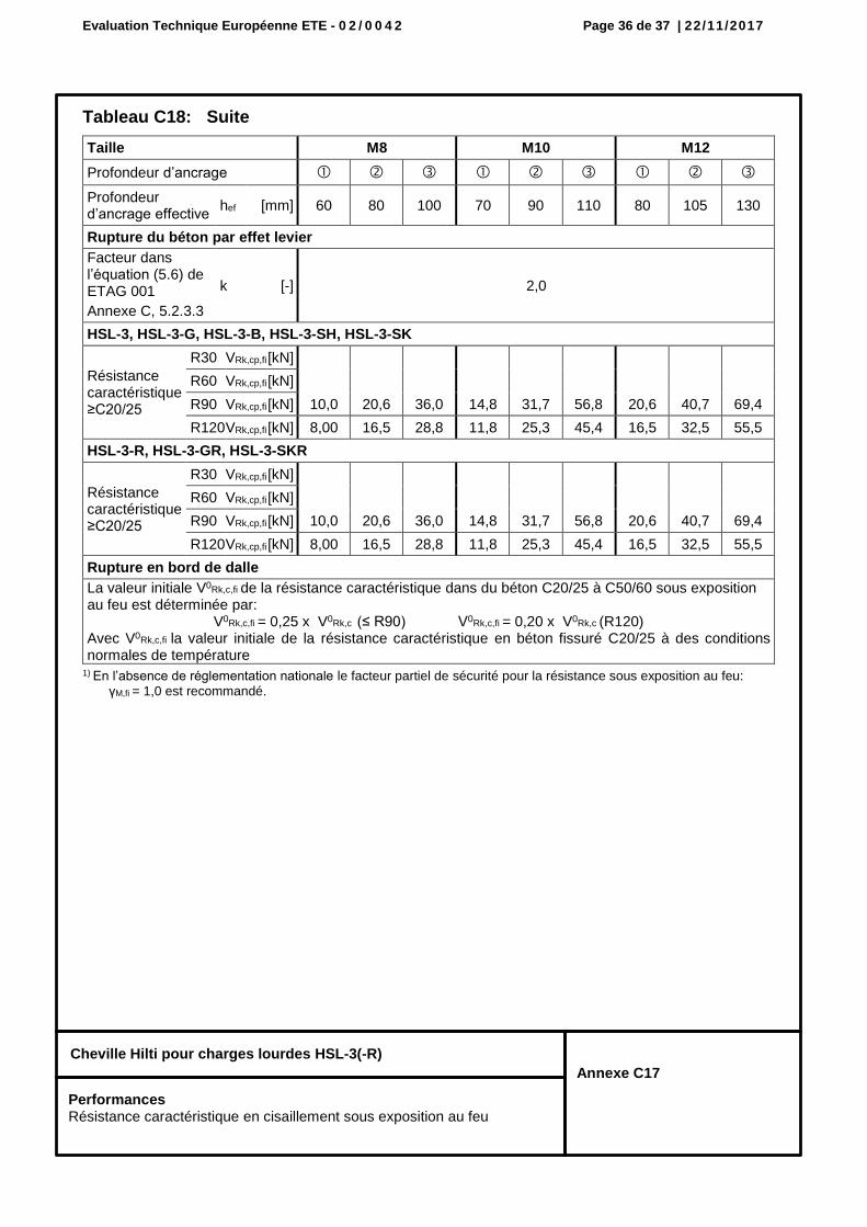
Performances Résistance caractéristique en cisaillement sous exposition au feu
Tableau C18: Suite
1) En l’absence de réglementation nationale le facteur partiel de sécurité pour la résistance sous exposition au feu: γM,fi = 1,0 est recommandé.
Taille M8 M10 M12
Profondeur d’ancrage
Profondeur d’ancrage effective
hef [mm] 60 80 100 70 90 110 80 105 130
Rupture du béton par effet levier
Facteur dans l’équation (5.6) de ETAG 001
Annexe C, 5.2.3.3
k [-] 2,0
HSL-3, HSL-3-G, HSL-3-B, HSL-3-SH, HSL-3-SK
Résistance caractéristique ≥C20/25
R30 VRk,cp,fi [kN]
10,0 20,6 36,0 14,8 31,7 56,8 20,6 40,7 69,4
R60 VRk,cp,fi [kN]
R90 VRk,cp,fi [kN]
R120 VRk,cp,fi [kN] 8,00 16,5 28,8 11,8 25,3 45,4 16,5 32,5 55,5
HSL-3-R, HSL-3-GR, HSL-3-SKR
Résistance caractéristique ≥C20/25
R30 VRk,cp,fi [kN]
10,0 20,6 36,0 14,8 31,7 56,8 20,6 40,7 69,4
R60 VRk,cp,fi [kN]
R90 VRk,cp,fi [kN]
R120 VRk,cp,fi [kN] 8,00 16,5 28,8 11,8 25,3 45,4 16,5 32,5 55,5
Rupture en bord de dalle
La valeur initiale V0Rk,c,fi de la résistance caractéristique dans du béton C20/25 à C50/60 sous exposition au feu est déterminée par:
V0Rk,c,fi = 0,25 x V0Rk,c (≤ R90) V0Rk,c,fi = 0,20 x V0Rk,c (R120) Avec V0Rk,c,fi la valeur initiale de la résistance caractéristique en béton fissuré C20/25 à des conditions normales de température
Evaluation Technique Européenne ETE - 0 2 / 0 0 4 2 Page 37 de 37 | 22/11/2017
Cheville Hilti pour charges lourdes HSL-3(-R)
Annexe C18
Performances Résistance caractéristique en cisaillement sous exposition au feu
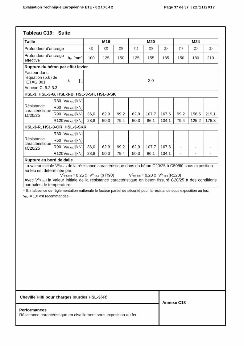
Tableau C19: Suite
1) En l’absence de réglementation nationale le facteur partiel de sécurité pour la résistance sous exposition au feu:
γM,fi = 1,0 est recommandée.
Taille M16 M20 M24
Profondeur d’ancrage
Profondeur d’ancrage effective
hef [mm] 100 125 150 125 155 185 150 180 210
Rupture du béton par effet levier
Facteur dans l’équation (5.6) de l’ETAG 001
Annexe C, 5.2.3.3
k [-] 2,0
HSL-3, HSL-3-G, HSL-3-B, HSL-3-SH, HSL-3-SK
Résistance caractéristique ≥C20/25
R30 VRk,cp,fi [kN]
36,0 62,9 99,2 62,9 107,7 167,6 99,2 156,5 219,1
R60 VRk,cp,fi [kN]
R90 VRk,cp,fi [kN]
R120 VRk,cp,fi [kN] 28,8 50,3 79,4 50,3 86,1 134,1 79,4 125,2 175,3
HSL-3-R, HSL-3-GR, HSL-3-SKR
Résistance caractéristique ≥C20/25
R30 VRk,cp,fi [kN]
36,0 62,9 99,2 62,9 107,7 167,6 - - -
R60 VRk,cp,fi [kN]
R90 VRk,cp,fi [kN]
R120 VRk,cp,fi [kN] 28,8 50,3 79,4 50,3 86,1 134,1 - - -
Rupture en bord de dalle
La valeur initiale V0Rk,c,fi de la résistance caractéristique dans du béton C20/25 à C50/60 sous exposition au feu est déterminée par:
V0Rk,c,fi = 0,25 x V0Rk,c (≤ R90) V0Rk,c,fi = 0,20 x V0Rk,c (R120) Avec V0Rk,c,fi la valeur initiale de la résistance caractéristique en béton fissuré C20/25 à des conditions normales de temperature
Centre Scientifique et
Technique du Bâtiment 84 avenue Jean Jaurès CHAMPS-SUR-MARNE F-77447 Marne-la-Vallée Cedex 2 Tél. : (33) 01 64 68 82 82 Fax : (33) 01 60 05 70 37
Member of
www.eota.eu
European Technical Assessment
ETA-02/0042 of 22/11/2017
English translation prepared by CSTB - Original version in French language
General Part
Nom commercial Trade name
Hilti HSL-3, HSL-3-R
Famille de produit Product family
Cheville métallique à expansion par vissage à couple contrôlé, pour béton fissuré et non fissuré
Torque-controlled expansion anchor for use in cracked and non-cracked concrete
Titulaire Manufacturer
Hilti Corporation Feldkircherstrasse 100 FL-9494 Schaan Principality of Liechtenstein
Usine de fabrication Manufacturing plants
Hilti plants
Cette évaluation contient: This assessment contains
37 pages incluant 34 pages d’annexes qui font partie intégrante de cette évaluation 37 pages including 34 pages of annexes which form an integral part of this assessment
Base de l‘ETE Basis of ETA
DEE 330232-00-0601 “Ancrages mécaniques dans le béton”
EAD 330232-00-0601 “Mechanical fasteners for use in concrete”
Cette évaluation remplace: This assessment replaces
ETE-02/0042 issue le 07/09/2015 ETA-02/0042 issued on 07/09/2015
Translations of this European Technical Assessment in other languages shall fully correspond to the original issued document and should be identified as such. Communication of this European Technical Assessment, including transmission by electronic means, shall be in full. However, partial reproduction may be made, with the written consent of the issuing Technical Assessment Body. Any partial reproduction has to be identified as such.
European technical assessment ETA-02/0042-2
English translation prepared by CSTB
Page 2 of 37 | 22 / 11 / 2017
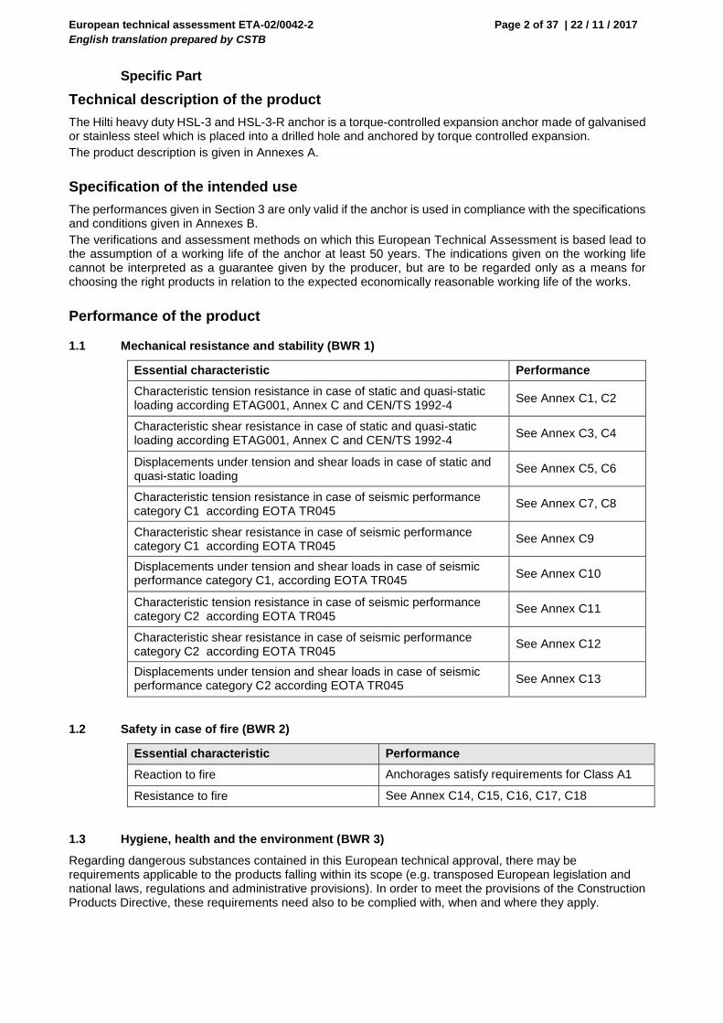
Specific Part
Technical description of the product
The Hilti heavy duty HSL-3 and HSL-3-R anchor is a torque-controlled expansion anchor made of galvanised or stainless steel which is placed into a drilled hole and anchored by torque controlled expansion.
The product description is given in Annexes A.
Specification of the intended use
The performances given in Section 3 are only valid if the anchor is used in compliance with the specifications and conditions given in Annexes B.
The verifications and assessment methods on which this European Technical Assessment is based lead to the assumption of a working life of the anchor at least 50 years. The indications given on the working life cannot be interpreted as a guarantee given by the producer, but are to be regarded only as a means for choosing the right products in relation to the expected economically reasonable working life of the works.
Performance of the product
1.1 Mechanical resistance and stability (BWR 1)
Essential characteristic Performance
Characteristic tension resistance in case of static and quasi-static loading according ETAG001, Annex C and CEN/TS 1992-4
See Annex C1, C2
Characteristic shear resistance in case of static and quasi-static loading according ETAG001, Annex C and CEN/TS 1992-4
See Annex C3, C4
Displacements under tension and shear loads in case of static and quasi-static loading
See Annex C5, C6
Characteristic tension resistance in case of seismic performance category C1 according EOTA TR045
See Annex C7, C8
Characteristic shear resistance in case of seismic performance category C1 according EOTA TR045
See Annex C9
Displacements under tension and shear loads in case of seismic performance category C1, according EOTA TR045
See Annex C10
Characteristic tension resistance in case of seismic performance category C2 according EOTA TR045
See Annex C11
Characteristic shear resistance in case of seismic performance category C2 according EOTA TR045
See Annex C12
Displacements under tension and shear loads in case of seismic performance category C2 according EOTA TR045
See Annex C13
1.2 Safety in case of fire (BWR 2)
Essential characteristic Performance
Reaction to fire Anchorages satisfy requirements for Class A1
Resistance to fire See Annex C14, C15, C16, C17, C18
1.3 Hygiene, health and the environment (BWR 3)
Regarding dangerous substances contained in this European technical approval, there may be requirements applicable to the products falling within its scope (e.g. transposed European legislation and national laws, regulations and administrative provisions). In order to meet the provisions of the Construction Products Directive, these requirements need also to be complied with, when and where they apply.
European technical assessment ETA-02/0042-2
English translation prepared by CSTB
Page 3 of 37 | 22 / 11 / 2017
1.4 Safety in use (BWR 4)
The essential characteristics regarding Safety in use are included under the Basic Works Requirement Mechanical resistance and stability.
1.5 Protection against noise (BWR 5)
Not relevant.
1.6 Energy economy and heat retention (BWR 6)
Not relevant.
1.7 Sustainable use of natural resources (BWR 7)
For the sustainable use of natural resources no performance was determined for this product.
1.8 General aspects relating to fitness for use
Durability and Serviceability are only ensured if the specifications of intended use according to Annex B1 are kept.
Assessment and verification of constancy of performance (AVCP)
According to the Decision 96/582/EC of the European Commission1, as amended, the system of assessment and verification of constancy of performance (see Annex V to Regulation (EU) No 305/2011) given in the following table apply.
Product Intended use Level
or Class System
Metal anchors for use in concrete
For fixing and/or supporting to concrete, structural elements (which contributes to the stability of the works) or heavy units
― 1
Technical details necessary for the implementation of the AVCP system
Technical details necessary for the implementation of the Assessment and verification of constancy of performance (AVCP) system are laid down in the control plan deposited at Centre Scientifique et Technique du Bâtiment.
The manufacturer shall, on the basis of a contract, involve a notified body approved in the field of anchors for issuing the certificate of conformity CE based on the control plan.
Issued in Marne La Vallée on 22-11-2017 by
Charles Baloche The original French version is signed
Directeur technique
1 Official Journal of the European Communities L 254 of 08.10.1996
European technical assessment ETA-02/0042
English translation prepared by CSTB
Page 4 of 37 | 22 / 11 / 2017
Hilti heavy duty anchor HSL-3(-R)
Annex A1
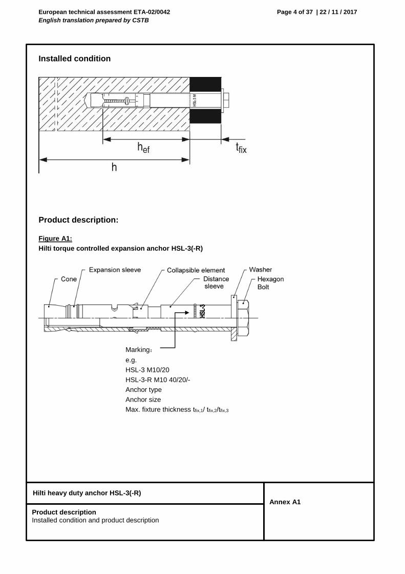
Installed condition
Product description:
Figure A1:
Hilti torque controlled expansion anchor HSL-3(-R)
Marking:
e.g.
HSL-3 M10/20
HSL-3-R M10 40/20/-
Anchor type
Anchor size
Max. fixture thickness tfix,1/ tfix,2/tfix,3
Product description Installed condition and product description
European technical assessment ETA-02/0042
English translation prepared by CSTB
Page 5 of 37 | 22 / 11 / 2017
Hilti heavy duty anchor HSL-3(-R)
Annex A2
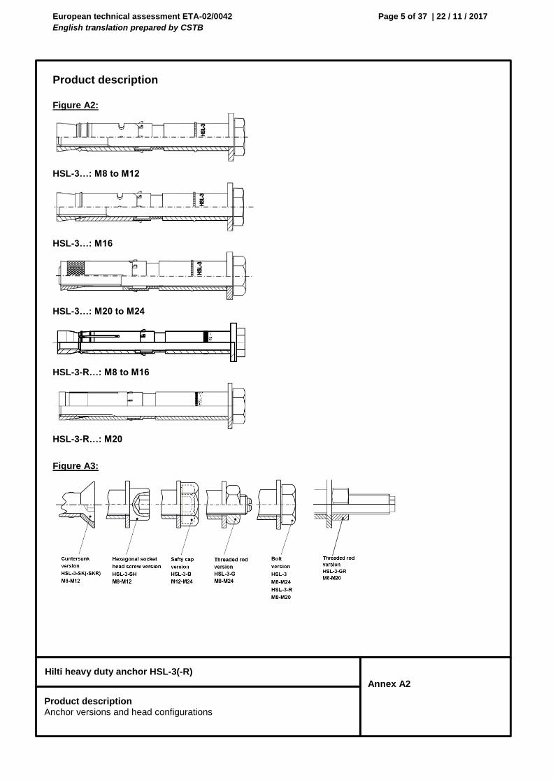
Product description
Figure A2:
HSL-3…: M8 to M12
HSL-3…: M16
HSL-3…: M20 to M24
HSL-3-R…: M8 to M16
HSL-3-R…: M20
Figure A3:
Product description Anchor versions and head configurations
European technical assessment ETA-02/0042
English translation prepared by CSTB
Page 6 of 37 | 22 / 11 / 2017
Hilti heavy duty anchor HSL-3(-R)
Annex A3
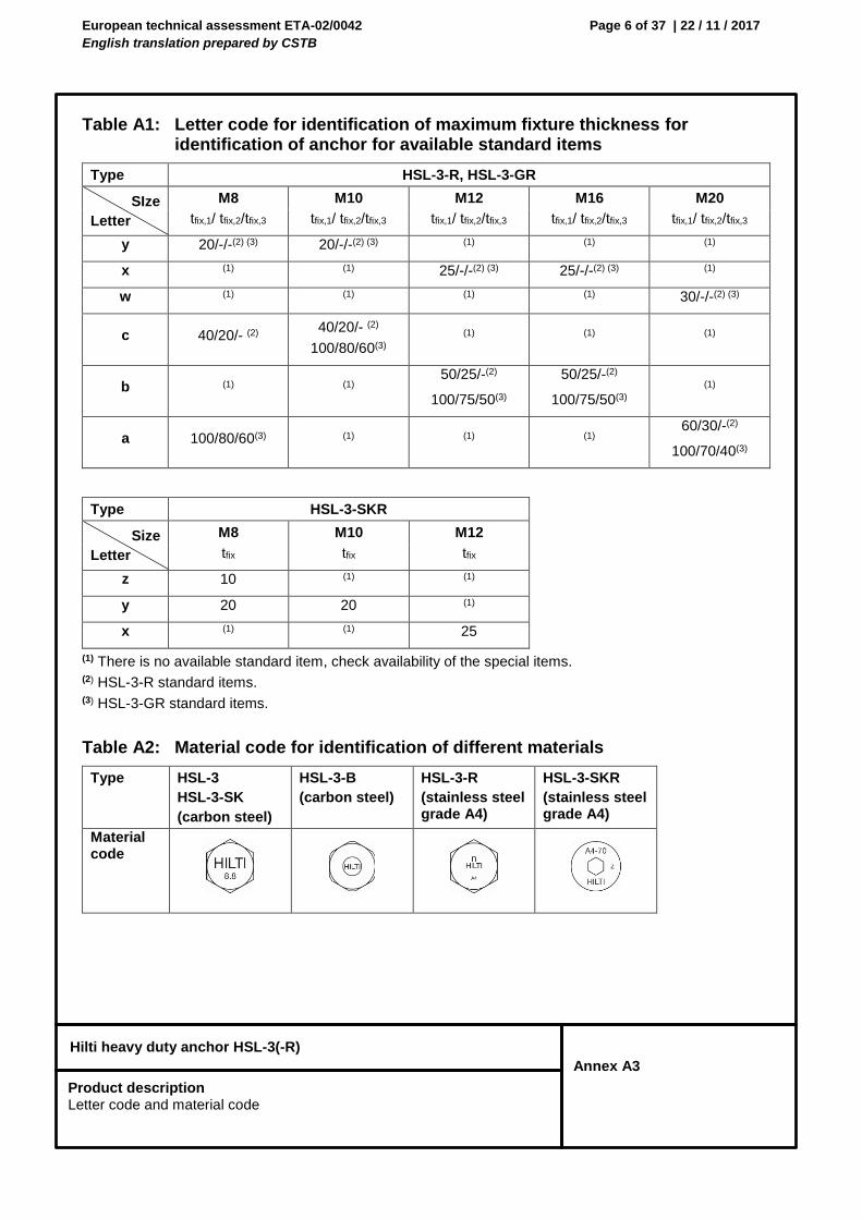
Table A1: Letter code for identification of maximum fixture thickness for identification of anchor for available standard items
Type HSL-3-R, HSL-3-GR
SIze
Letter
M8 M10 M12 M16 M20
tfix,1/ tfix,2/tfix,3 tfix,1/ tfix,2/tfix,3 tfix,1/ tfix,2/tfix,3 tfix,1/ tfix,2/tfix,3 tfix,1/ tfix,2/tfix,3
y 20/-/-(2) (3) 20/-/-(2) (3) (1) (1) (1)
x (1) (1) 25/-/-(2) (3) 25/-/-(2) (3) (1)
w (1) (1) (1) (1) 30/-/-(2) (3)
c 40/20/- (2) 40/20/- (2)
100/80/60(3)
(1) (1) (1)
b (1) (1) 50/25/-(2)
100/75/50(3)
50/25/-(2)
100/75/50(3)
(1)
a 100/80/60(3) (1) (1) (1) 60/30/-(2)
100/70/40(3)
Type HSL-3-SKR
Size
Letter
M8 M10 M12
tfix tfix tfix
z 10 (1) (1)
y 20 20 (1)
x (1) (1) 25
(1) There is no available standard item, check availability of the special items. (2) HSL-3-R standard items. (3) HSL-3-GR standard items.
Table A2: Material code for identification of different materials
Type HSL-3
HSL-3-SK
(carbon steel)
HSL-3-B
(carbon steel)
HSL-3-R
(stainless steel grade A4)
HSL-3-SKR
(stainless steel grade A4)
Material code
Product description Letter code and material code
European technical assessment ETA-02/0042
English translation prepared by CSTB
Page 7 of 37 | 22 / 11 / 2017
Hilti heavy duty anchor HSL-3(-R)
Annex A4
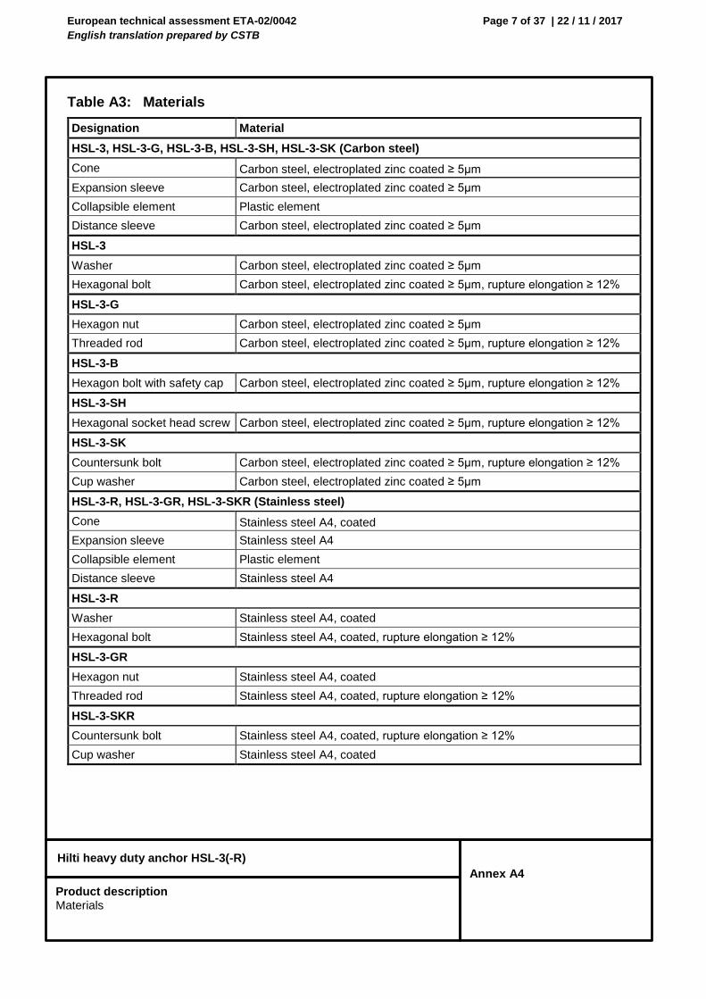
Table A3: Materials
Designation Material
HSL-3, HSL-3-G, HSL-3-B, HSL-3-SH, HSL-3-SK (Carbon steel)
Cone Carbon steel, electroplated zinc coated ≥ 5µm
Expansion sleeve Carbon steel, electroplated zinc coated ≥ 5µm
Collapsible element Plastic element
Distance sleeve Carbon steel, electroplated zinc coated ≥ 5µm
HSL-3
Washer Carbon steel, electroplated zinc coated ≥ 5µm
Hexagonal bolt Carbon steel, electroplated zinc coated ≥ 5µm, rupture elongation ≥ 12%
HSL-3-G
Hexagon nut Carbon steel, electroplated zinc coated ≥ 5µm
Threaded rod Carbon steel, electroplated zinc coated ≥ 5µm, rupture elongation ≥ 12%
HSL-3-B
Hexagon bolt with safety cap Carbon steel, electroplated zinc coated ≥ 5µm, rupture elongation ≥ 12%
HSL-3-SH
Hexagonal socket head screw Carbon steel, electroplated zinc coated ≥ 5µm, rupture elongation ≥ 12%
HSL-3-SK
Countersunk bolt Carbon steel, electroplated zinc coated ≥ 5µm, rupture elongation ≥ 12%
Cup washer Carbon steel, electroplated zinc coated ≥ 5µm
HSL-3-R, HSL-3-GR, HSL-3-SKR (Stainless steel)
Cone Stainless steel A4, coated
Expansion sleeve Stainless steel A4
Collapsible element Plastic element
Distance sleeve Stainless steel A4
HSL-3-R
Washer Stainless steel A4, coated
Hexagonal bolt Stainless steel A4, coated, rupture elongation ≥ 12%
HSL-3-GR
Hexagon nut Stainless steel A4, coated
Threaded rod Stainless steel A4, coated, rupture elongation ≥ 12%
HSL-3-SKR
Countersunk bolt Stainless steel A4, coated, rupture elongation ≥ 12%
Cup washer Stainless steel A4, coated
Product description Materials
European technical assessment ETA-02/0042
English translation prepared by CSTB
Page 8 of 37 | 22 / 11 / 2017
Hilti heavy duty anchor HSL-3(-R)
Annex B1
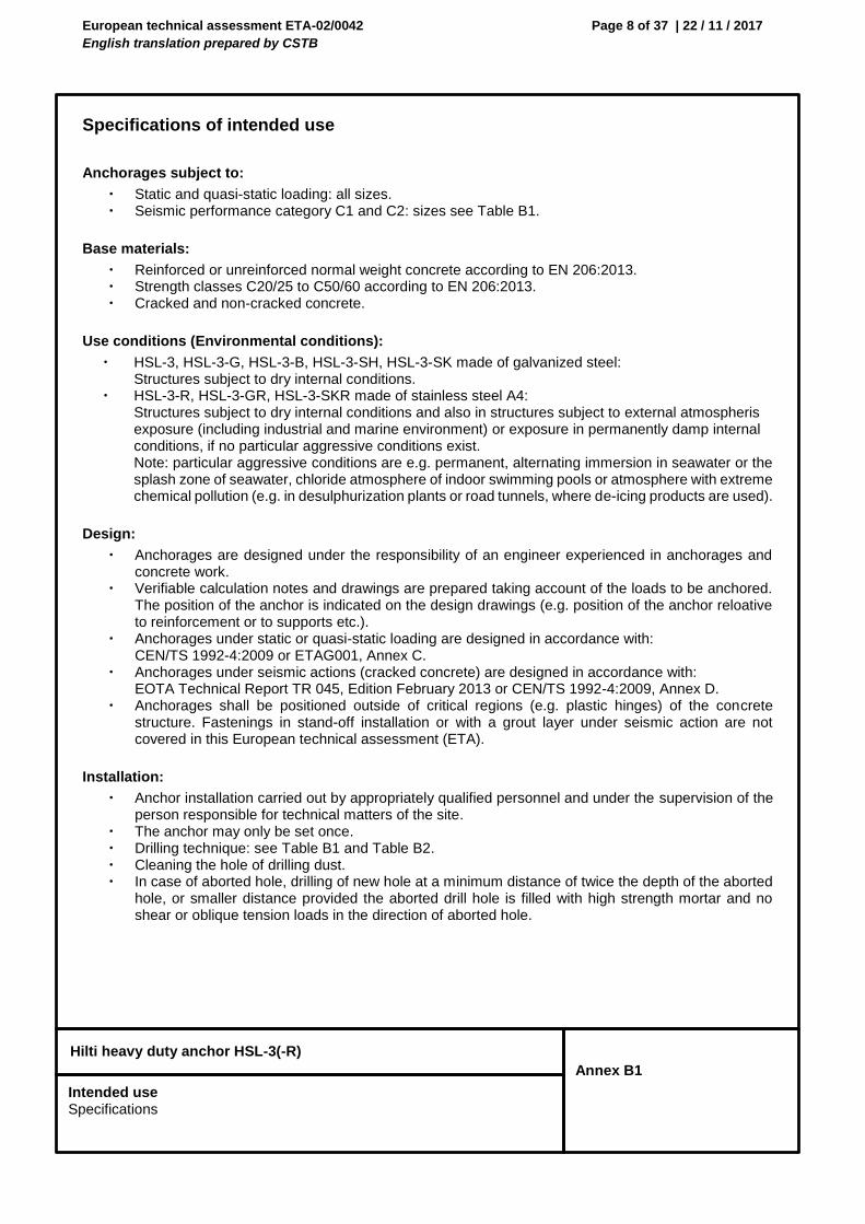
Specifications of intended use
Anchorages subject to:
Static and quasi-static loading: all sizes. Seismic performance category C1 and C2: sizes see Table B1.
Base materials:
Reinforced or unreinforced normal weight concrete according to EN 206:2013. Strength classes C20/25 to C50/60 according to EN 206:2013. Cracked and non-cracked concrete.
Use conditions (Environmental conditions):
HSL-3, HSL-3-G, HSL-3-B, HSL-3-SH, HSL-3-SK made of galvanized steel: Structures subject to dry internal conditions.
HSL-3-R, HSL-3-GR, HSL-3-SKR made of stainless steel A4: Structures subject to dry internal conditions and also in structures subject to external atmospheris exposure (including industrial and marine environment) or exposure in permanently damp internal conditions, if no particular aggressive conditions exist. Note: particular aggressive conditions are e.g. permanent, alternating immersion in seawater or the splash zone of seawater, chloride atmosphere of indoor swimming pools or atmosphere with extreme chemical pollution (e.g. in desulphurization plants or road tunnels, where de-icing products are used).
Design:
Anchorages are designed under the responsibility of an engineer experienced in anchorages and concrete work.
Verifiable calculation notes and drawings are prepared taking account of the loads to be anchored. The position of the anchor is indicated on the design drawings (e.g. position of the anchor reloative to reinforcement or to supports etc.).
Anchorages under static or quasi-static loading are designed in accordance with: CEN/TS 1992-4:2009 or ETAG001, Annex C.
Anchorages under seismic actions (cracked concrete) are designed in accordance with: EOTA Technical Report TR 045, Edition February 2013 or CEN/TS 1992-4:2009, Annex D.
Anchorages shall be positioned outside of critical regions (e.g. plastic hinges) of the concrete structure. Fastenings in stand-off installation or with a grout layer under seismic action are not covered in this European technical assessment (ETA).
Installation:
Anchor installation carried out by appropriately qualified personnel and under the supervision of the person responsible for technical matters of the site.
The anchor may only be set once. Drilling technique: see Table B1 and Table B2. Cleaning the hole of drilling dust. In case of aborted hole, drilling of new hole at a minimum distance of twice the depth of the aborted
hole, or smaller distance provided the aborted drill hole is filled with high strength mortar and no shear or oblique tension loads in the direction of aborted hole.
Intended use Specifications
European technical assessment ETA-02/0042
English translation prepared by CSTB
Page 9 of 37 | 22 / 11 / 2017
Hilti heavy duty anchor HSL-3(-R)
Annex B2
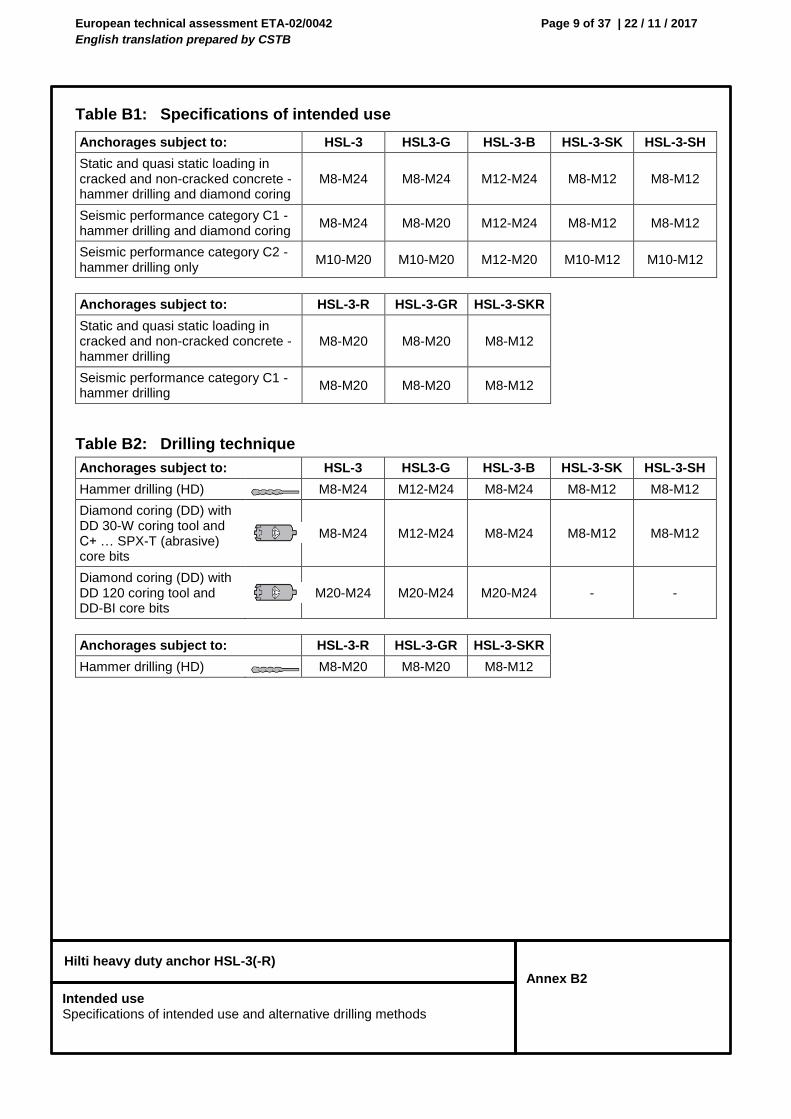
Table B1: Specifications of intended use
Anchorages subject to: HSL-3 HSL3-G HSL-3-B HSL-3-SK HSL-3-SH
Static and quasi static loading in cracked and non-cracked concrete - hammer drilling and diamond coring
M8-M24 M8-M24 M12-M24 M8-M12 M8-M12
Seismic performance category C1 - hammer drilling and diamond coring
M8-M24 M8-M20 M12-M24 M8-M12 M8-M12
Seismic performance category C2 - hammer drilling only
M10-M20 M10-M20 M12-M20 M10-M12 M10-M12
Anchorages subject to: HSL-3-R HSL-3-GR HSL-3-SKR
Static and quasi static loading in cracked and non-cracked concrete - hammer drilling
M8-M20 M8-M20 M8-M12
Seismic performance category C1 - hammer drilling
M8-M20 M8-M20 M8-M12
Table B2: Drilling technique
Anchorages subject to: HSL-3 HSL3-G HSL-3-B HSL-3-SK HSL-3-SH
Hammer drilling (HD) M8-M24 M12-M24 M8-M24 M8-M12 M8-M12
Diamond coring (DD) with DD 30-W coring tool and C+ … SPX-T (abrasive) core bits
M8-M24 M12-M24 M8-M24 M8-M12 M8-M12
Diamond coring (DD) with DD 120 coring tool and DD-BI core bits
M20-M24 M20-M24 M20-M24 - -
Anchorages subject to: HSL-3-R HSL-3-GR HSL-3-SKR
Hammer drilling (HD) M8-M20 M8-M20 M8-M12
Intended use Specifications of intended use and alternative drilling methods
European technical assessment ETA-02/0042
English translation prepared by CSTB
Page 10 of 37 | 22 / 11 / 2017
Hilti heavy duty anchor HSL-3(-R)
Annex B3
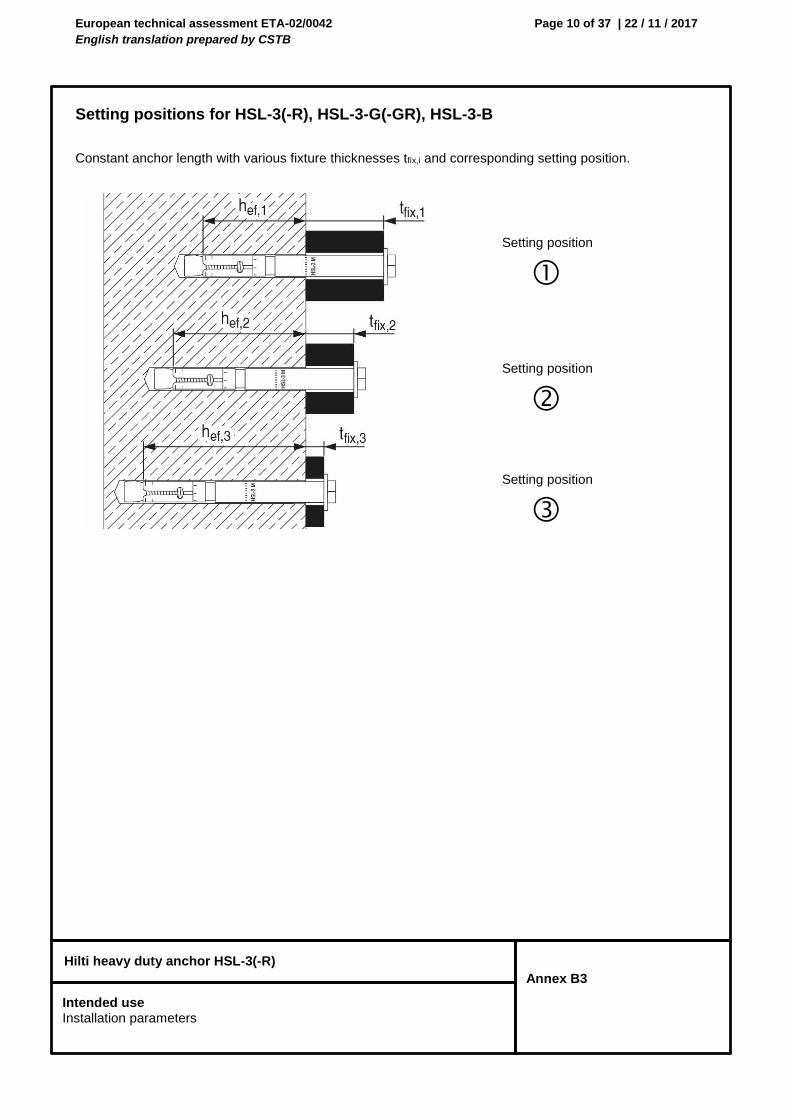
Setting positions for HSL-3(-R), HSL-3-G(-GR), HSL-3-B
Constant anchor length with various fixture thicknesses tfix,i and corresponding setting position.
Setting position
Setting position
Setting position
Intended use Installation parameters
European technical assessment ETA-02/0042
English translation prepared by CSTB
Page 11 of 37 | 22 / 11 / 2017
Hilti heavy duty anchor HSL-3(-R)
Annex B4
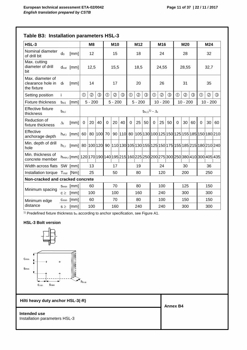
Table B3: Installation parameters HSL-3
1) Predefined fixture thickness tfix according to anchor specification, see Figure A1.
HSL-3 Bolt version
HSL-3 M8 M10 M12 M16 M20 M24
Nominal diameter of drill bit
d0 [mm] 12 15 18 24 28 32
Max. cutting diameter of drill bit
dcut [mm] 12,5 15,5 18,5 24,55 28,55 32,7
Max. diameter of clearance hole in the fixture
df [mm] 14 17 20 26 31 35
Setting position i
Fixture thickness tfix1 [mm] 5 - 200 5 - 200 5 - 200 10 - 200 10 - 200 10 - 200
Effective fixture thickness
tfix,i tfix,11) - i
Reduction of fixture thickness
i [mm] 0 20 40 0 20 40 0 25 50 0 25 50 0 30 60 0 30 60
Effective anchorage depth
hef,i [mm] 60 80 100 70 90 110 80 105 130 100 125 150 125 155 185 150 180 210
Min. depth of drill hole
h1,i [mm] 80 100 120 90 110 130 105 130 155 125 150 175 155 185 215 180 210 240
Min. thickness of concrete member
hmin,i [mm] 120 170 190 140 195 215 160 225 250 200 275 300 250 380 410 300 405 435
Width across flats SW [mm] 13 17 19 24 30 36
Installation torque Tinst [Nm] 25 50 80 120 200 250
Non-cracked and cracked concrete
Minimum spacing smin [mm] 60 70 80 100 125 150
c [mm] 100 100 160 240 300 300
Minimum edge distance
cmin [mm] 60 70 80 100 150 150
s [mm] 100 160 240 240 300 300
Intended use Installation parameters HSL-3
European technical assessment ETA-02/0042
English translation prepared by CSTB
Page 12 of 37 | 22 / 11 / 2017
Hilti heavy duty anchor HSL-3(-R)
Annex B5
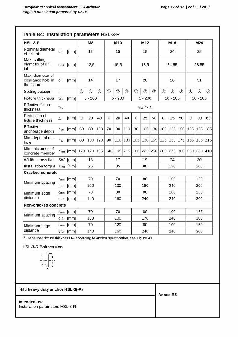
Table B4: Installation parameters HSL-3-R
1) Predefined fixture thickness tfix according to anchor specification, see Figure A1.
HSL-3-R Bolt version
HSL-3-R M8 M10 M12 M16 M20
Nominal diameter of drill bit
d0 [mm] 12 15 18 24 28
Max. cutting diameter of drill bit
dcut [mm] 12,5 15,5 18,5 24,55 28,55
Max. diameter of clearance hole in the fixture
df [mm] 14 17 20 26 31
Setting position i
Fixture thickness tfix1 [mm] 5 - 200 5 - 200 5 - 200 10 - 200 10 - 200
Effective fixture thickness
tfix,i tfix,11) - i
Reduction of fixture thickness
i [mm] 0 20 40 0 20 40 0 25 50 0 25 50 0 30 60
Effective anchorage depth
hef,i [mm] 60 80 100 70 90 110 80 105 130 100 125 150 125 155 185
Min. depth of drill hole
h1,i [mm] 80 100 120 90 110 130 105 130 155 125 150 175 155 185 215
Min. thickness of concrete member
hmin,i [mm] 120 170 195 140 195 215 160 225 250 200 275 300 250 380 410
Width across flats SW [mm] 13 17 19 24 30
Installation torque Tinst [Nm] 25 35 80 120 200
Cracked concrete
Minimum spacing smin [mm] 70 70 80 100 125
c [mm] 100 100 160 240 300
Minimum edge distance
cmin [mm] 70 80 80 100 150
s [mm] 140 160 240 240 300
Non-cracked concrete
Minimum spacing smin [mm] 70 70 80 100 125
c [mm] 100 100 170 240 300
Minimum edge distance
cmin [mm] 70 120 80 100 150
s [mm] 140 160 240 240 300
Intended use Installation parameters HSL-3-R
European technical assessment ETA-02/0042
English translation prepared by CSTB
Page 13 of 37 | 22 / 11 / 2017
Hilti heavy duty anchor HSL-3(-R)
Annex B6
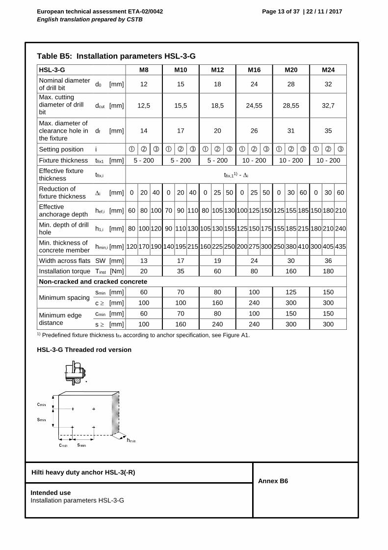
Table B5: Installation parameters HSL-3-G
1) Predefined fixture thickness tfix according to anchor specification, see Figure A1.
HSL-3-G Threaded rod version
HSL-3-G M8 M10 M12 M16 M20 M24
Nominal diameter of drill bit
d0 [mm] 12 15 18 24 28 32
Max. cutting diameter of drill bit
dcut [mm] 12,5 15,5 18,5 24,55 28,55 32,7
Max. diameter of clearance hole in the fixture
df [mm] 14 17 20 26 31 35
Setting position i
Fixture thickness tfix1 [mm] 5 - 200 5 - 200 5 - 200 10 - 200 10 - 200 10 - 200
Effective fixture thickness
tfix,i tfix,11) - i
Reduction of fixture thickness
i [mm] 0 20 40 0 20 40 0 25 50 0 25 50 0 30 60 0 30 60
Effective anchorage depth
hef,i [mm] 60 80 100 70 90 110 80 105 130 100 125 150 125 155 185 150 180 210
Min. depth of drill hole
h1,i [mm] 80 100 120 90 110 130 105 130 155 125 150 175 155 185 215 180 210 240
Min. thickness of concrete member
hmin,i [mm] 120 170 190 140 195 215 160 225 250 200 275 300 250 380 410 300 405 435
Width across flats SW [mm] 13 17 19 24 30 36
Installation torque Tinst [Nm] 20 35 60 80 160 180
Non-cracked and cracked concrete
Minimum spacing smin [mm] 60 70 80 100 125 150
c [mm] 100 100 160 240 300 300
Minimum edge distance
cmin [mm] 60 70 80 100 150 150
s [mm] 100 160 240 240 300 300
Intended use Installation parameters HSL-3-G
European technical assessment ETA-02/0042
English translation prepared by CSTB
Page 14 of 37 | 22 / 11 / 2017
Hilti heavy duty anchor HSL-3(-R)
Annex B7
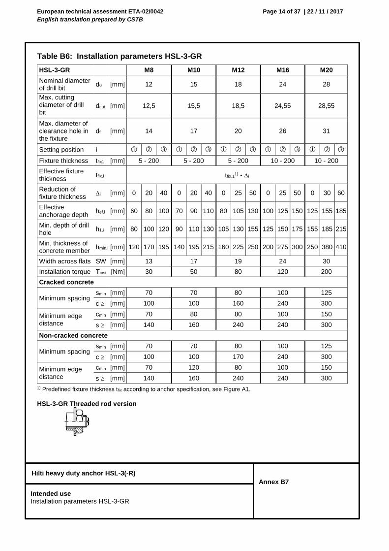
Table B6: Installation parameters HSL-3-GR
1) Predefined fixture thickness tfix according to anchor specification, see Figure A1.
HSL-3-GR Threaded rod version
HSL-3-GR M8 M10 M12 M16 M20
Nominal diameter of drill bit
d0 [mm] 12 15 18 24 28
Max. cutting diameter of drill bit
dcut [mm] 12,5 15,5 18,5 24,55 28,55
Max. diameter of clearance hole in the fixture
df [mm] 14 17 20 26 31
Setting position i
Fixture thickness tfix1 [mm] 5 - 200 5 - 200 5 - 200 10 - 200 10 - 200
Effective fixture thickness
tfix,i tfix,11) - i
Reduction of fixture thickness
i [mm] 0 20 40 0 20 40 0 25 50 0 25 50 0 30 60
Effective anchorage depth
hef,i [mm] 60 80 100 70 90 110 80 105 130 100 125 150 125 155 185
Min. depth of drill hole
h1,i [mm] 80 100 120 90 110 130 105 130 155 125 150 175 155 185 215
Min. thickness of concrete member
hmin,i [mm] 120 170 195 140 195 215 160 225 250 200 275 300 250 380 410
Width across flats SW [mm] 13 17 19 24 30
Installation torque Tinst [Nm] 30 50 80 120 200
Cracked concrete
Minimum spacing smin [mm] 70 70 80 100 125
c [mm] 100 100 160 240 300
Minimum edge distance
cmin [mm] 70 80 80 100 150
s [mm] 140 160 240 240 300
Non-cracked concrete
Minimum spacing smin [mm] 70 70 80 100 125
c [mm] 100 100 170 240 300
Minimum edge distance
cmin [mm] 70 120 80 100 150
s [mm] 140 160 240 240 300
Intended use Installation parameters HSL-3-GR
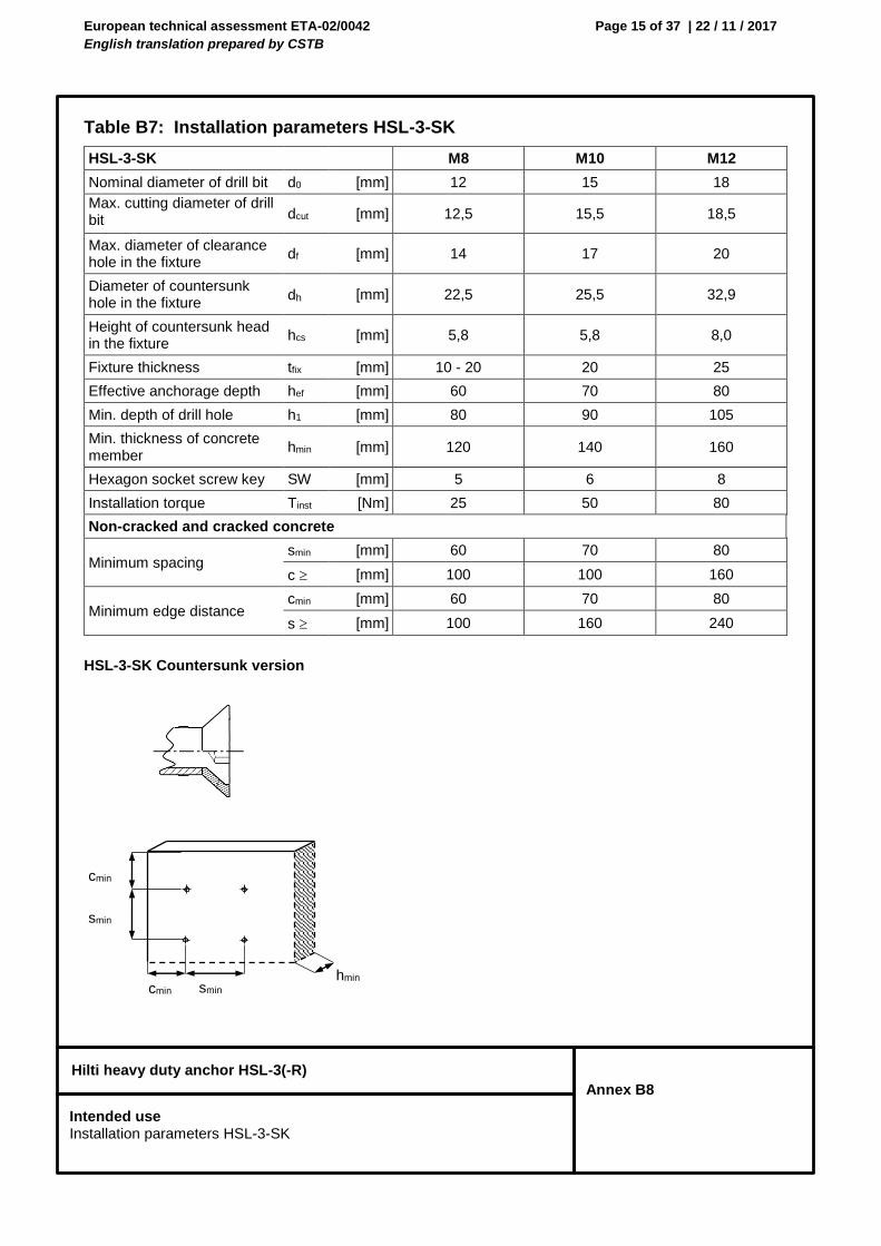
European technical assessment ETA-02/0042
English translation prepared by CSTB
Page 15 of 37 | 22 / 11 / 2017
Hilti heavy duty anchor HSL-3(-R)
Annex B8
Table B7: Installation parameters HSL-3-SK
HSL-3-SK Countersunk version
HSL-3-SK M8 M10 M12
Nominal diameter of drill bit d0 [mm] 12 15 18
Max. cutting diameter of drill bit dcut [mm] 12,5 15,5 18,5
Max. diameter of clearance hole in the fixture
df [mm] 14 17 20
Diameter of countersunk hole in the fixture
dh [mm] 22,5 25,5 32,9
Height of countersunk head in the fixture
hcs [mm] 5,8 5,8 8,0
Fixture thickness tfix [mm] 10 - 20 20 25
Effective anchorage depth hef [mm] 60 70 80
Min. depth of drill hole h1 [mm] 80 90 105
Min. thickness of concrete member
hmin [mm] 120 140 160
Hexagon socket screw key SW [mm] 5 6 8
Installation torque Tinst [Nm] 25 50 80
Non-cracked and cracked concrete
Minimum spacing smin [mm] 60 70 80
c [mm] 100 100 160
Minimum edge distance cmin [mm] 60 70 80
s [mm] 100 160 240
cmin
cmin hmin
smin
smin
Intended use Installation parameters HSL-3-SK
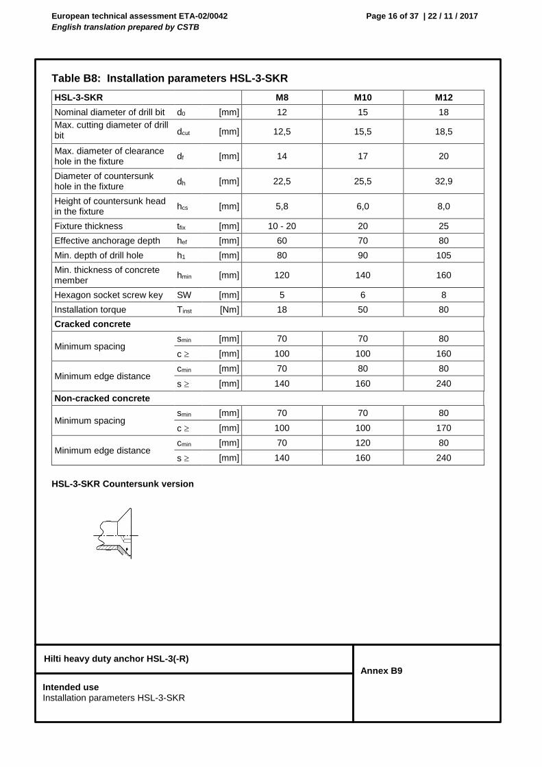
European technical assessment ETA-02/0042
English translation prepared by CSTB
Page 16 of 37 | 22 / 11 / 2017
Hilti heavy duty anchor HSL-3(-R)
Annex B9
Table B8: Installation parameters HSL-3-SKR
HSL-3-SKR Countersunk version
HSL-3-SKR M8 M10 M12
Nominal diameter of drill bit d0 [mm] 12 15 18
Max. cutting diameter of drill bit dcut [mm] 12,5 15,5 18,5
Max. diameter of clearance hole in the fixture
df [mm] 14 17 20
Diameter of countersunk hole in the fixture
dh [mm] 22,5 25,5 32,9
Height of countersunk head in the fixture
hcs [mm] 5,8 6,0 8,0
Fixture thickness tfix [mm] 10 - 20 20 25
Effective anchorage depth hef [mm] 60 70 80
Min. depth of drill hole h1 [mm] 80 90 105
Min. thickness of concrete member
hmin [mm] 120 140 160
Hexagon socket screw key SW [mm] 5 6 8
Installation torque Tinst [Nm] 18 50 80
Cracked concrete
Minimum spacing smin [mm] 70 70 80
c [mm] 100 100 160
Minimum edge distance cmin [mm] 70 80 80
s [mm] 140 160 240
Non-cracked concrete
Minimum spacing smin [mm] 70 70 80
c [mm] 100 100 170
Minimum edge distance cmin [mm] 70 120 80
s [mm] 140 160 240
Intended use Installation parameters HSL-3-SKR
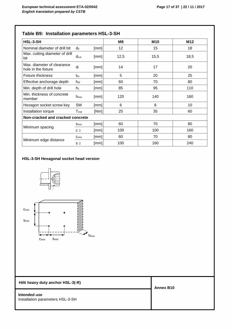
European technical assessment ETA-02/0042
English translation prepared by CSTB
Page 17 of 37 | 22 / 11 / 2017
Hilti heavy duty anchor HSL-3(-R)
Annex B10
Table B9: Installation parameters HSL-3-SH
HSL-3-SH Hexagonal socket head version
HSL-3-SH M8 M10 M12
Nominal diameter of drill bit d0 [mm] 12 15 18
Max. cutting diameter of drill bit dcut [mm] 12,5 15,5 18,5
Max. diameter of clearance hole in the fixture
df [mm] 14 17 20
Fixture thickness tfix [mm] 5 20 25
Effective anchorage depth hef [mm] 60 70 80
Min. depth of drill hole h1 [mm] 85 95 110
Min. thickness of concrete member
hmin [mm] 120 140 160
Hexagon socket screw key SW [mm] 6 8 10
Installation torque Tinst [Nm] 25 35 60
Non-cracked and cracked concrete
Minimum spacing smin [mm] 60 70 80
c [mm] 100 100 160
Minimum edge distance cmin [mm] 60 70 80
s [mm] 100 160 240
cmin
cmin hmin
smin
smin
Intended use Installation parameters HSL-3-SH
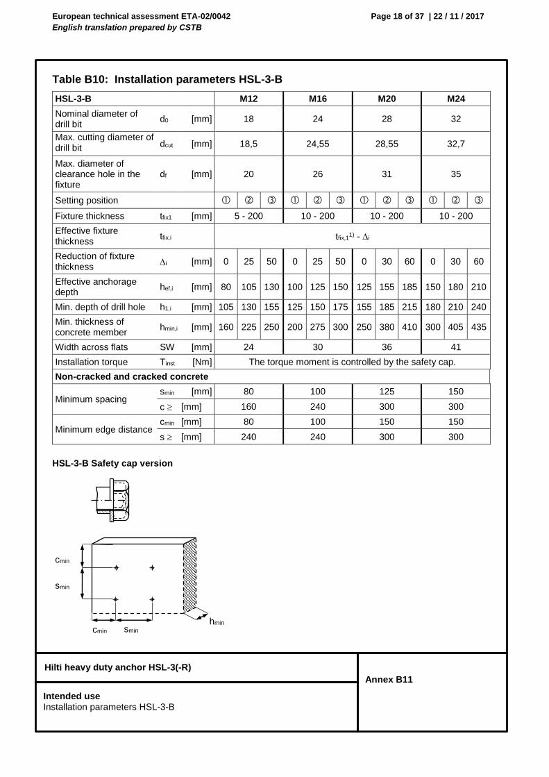
European technical assessment ETA-02/0042
English translation prepared by CSTB
Page 18 of 37 | 22 / 11 / 2017
Hilti heavy duty anchor HSL-3(-R)
Annex B11
Table B10: Installation parameters HSL-3-B
HSL-3-B Safety cap version
HSL-3-B M12 M16 M20 M24
Nominal diameter of drill bit
d0 [mm] 18 24 28 32
Max. cutting diameter of drill bit dcut [mm] 18,5 24,55 28,55 32,7
Max. diameter of clearance hole in the fixture
df [mm] 20 26 31 35
Setting position
Fixture thickness tfix1 [mm] 5 - 200 10 - 200 10 - 200 10 - 200
Effective fixture thickness
tfix,i tfix,11) - i
Reduction of fixture thickness
i [mm] 0 25 50 0 25 50 0 30 60 0 30 60
Effective anchorage depth
hef,i [mm] 80 105 130 100 125 150 125 155 185 150 180 210
Min. depth of drill hole h1,i [mm] 105 130 155 125 150 175 155 185 215 180 210 240
Min. thickness of concrete member
hmin,i [mm] 160 225 250 200 275 300 250 380 410 300 405 435
Width across flats SW [mm] 24 30 36 41
Installation torque Tinst [Nm] The torque moment is controlled by the safety cap.
Non-cracked and cracked concrete
Minimum spacing smin [mm] 80 100 125 150
c [mm] 160 240 300 300
Minimum edge distance cmin [mm] 80 100 150 150
s [mm] 240 240 300 300
cmin
cmin hmin
smin
smin
Intended use Installation parameters HSL-3-B
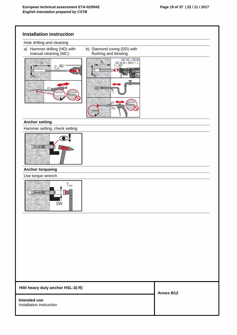
European technical assessment ETA-02/0042
English translation prepared by CSTB
Page 19 of 37 | 22 / 11 / 2017
Hilti heavy duty anchor HSL-3(-R)
Annex B12
Installation instruction
Hole drilling and cleaning
a) Hammer drilling (HD) with manual cleaning (MC):
b) Diamond coring (DD) with flushing and blowing
Anchor setting
Hammer setting, check setting
Anchor torqueing
Use torque wrench
Intended use Installation instruction
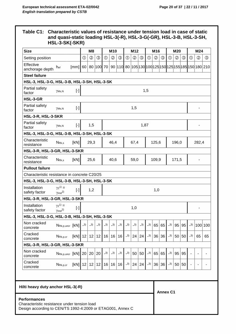
European technical assessment ETA-02/0042
English translation prepared by CSTB
Page 20 of 37 | 22 / 11 / 2017
Hilti heavy duty anchor HSL-3(-R)
Annex C1
Table C1: Characteristic values of resistance under tension load in case of static and quasi-static loading HSL-3(-R), HSL-3-G(-GR), HSL-3-B, HSL-3-SH, HSL-3-SK(-SKR)
Size M8 M10 M12 M16 M20 M24
Setting position
Effective anchorage depth
hef [mm] 60 80 100 70 90 110 80 105 130 100 125 150 125 155 185 150 180 210
Steel failure
HSL-3, HSL-3-G, HSL-3-B, HSL-3-SH, HSL-3-SK
Partial safety factor
Ms,N [-] 1,5
HSL-3-GR
Partial safety factor
Ms,N [-] 1,5 -
HSL-3-R, HSL-3-SKR
Partial safety factor
Ms,N [-] 1,5 1,87 -
HSL-3, HSL-3-G, HSL-3-B, HSL-3-SH, HSL-3-SK
Characteristic resistance
NRk,s [kN] 29,3 46,4 67,4 125,6 196,0 282,4
HSL-3-R, HSL-3-GR, HSL-3-SKR
Characteristic resistance
NRk,s [kN] 25,6 40,6 59,0 109,9 171,5 -
Pullout failure
Characteristic resistance in concrete C20/25
HSL-3, HSL-3-G, HSL-3-B, HSL-3-SH, HSL-3-SK
Installation safety factor
21) =
inst2)
[-] 1,2 1,0
HSL-3-R, HSL-3-GR, HSL-3-SKR
Installation safety factor
21) =
inst2)
[-] 1,0 -
HSL-3, HSL-3-G, HSL-3-B, HSL-3-SH, HSL-3-SK
Non cracked concrete
NRk,p,uncr [kN] -3) -3) -3) -3) -3) -3) -3) -3) -3) -3) 65 65 -3) 95 95 -3) 100 100
Cracked concrete
NRk,p,cr [kN] 12 12 12 16 16 16 -3) 24 24 -3) 36 36 -3) 50 50 -3) 65 65
HSL-3-R, HSL-3-GR, HSL-3-SKR
Non cracked concrete
NRk,p,uncr [kN] 20 20 20 -3) -3) -3) -3) 50 50 -3) 65 65 -3) 95 95 - - -
Cracked concrete
NRk,p,cr [kN] 12 12 12 16 16 16 -3) 24 24 -3) 36 36 -3) 50 50 - - -
Performances Characteristic resistance under tension load Design according to CEN/TS 1992-4:2009 or ETAG001, Annex C
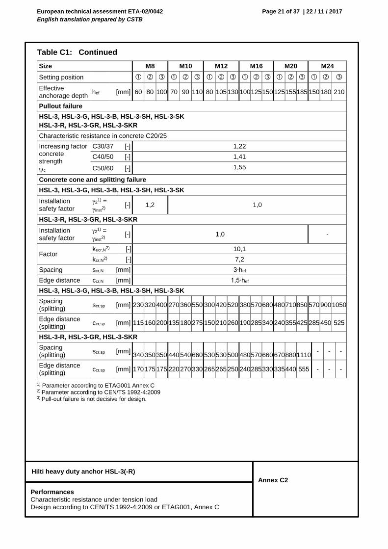
European technical assessment ETA-02/0042
English translation prepared by CSTB
Page 21 of 37 | 22 / 11 / 2017
Hilti heavy duty anchor HSL-3(-R)
Annex C2
Table C1: Continued
1) Parameter according to ETAG001 Annex C 2) Parameter according to CEN/TS 1992-4:2009 3) Pull-out failure is not decisive for design.
Size M8 M10 M12 M16 M20 M24
Setting position
Effective anchorage depth
hef [mm] 60 80 100 70 90 110 80 105 130 100 125 150 125 155 185 150 180 210
Pullout failure
HSL-3, HSL-3-G, HSL-3-B, HSL-3-SH, HSL-3-SK
HSL-3-R, HSL-3-GR, HSL-3-SKR
Characteristic resistance in concrete C20/25
Increasing factor concrete strength
c
C30/37 [-] 1,22
C40/50 [-] 1,41
C50/60 [-] 1,55
Concrete cone and splitting failure
HSL-3, HSL-3-G, HSL-3-B, HSL-3-SH, HSL-3-SK
Installation safety factor
21) =
inst2)
[-] 1,2 1,0
HSL-3-R, HSL-3-GR, HSL-3-SKR
Installation safety factor
21) =
inst2)
[-] 1,0 -
Factor kucr,N
2) [-] 10,1
kcr,N2) [-] 7,2
Spacing scr,N [mm] 3∙hef
Edge distance ccr,N [mm] 1,5∙hef
HSL-3, HSL-3-G, HSL-3-B, HSL-3-SH, HSL-3-SK
Spacing (splitting)
scr,sp [mm] 230 320 400 270 360 550 300 420 520 380 570 680 480 710 850 570 900 1050
Edge distance (splitting)
ccr,sp [mm] 115 160 200 135 180 275 150 210 260 190 285 340 240 355 425 285 450 525
HSL-3-R, HSL-3-GR, HSL-3-SKR
Spacing (splitting)
scr,sp [mm] 340 350 350 440 540 660 530 530 500 480 570 660 670 880 1110
- - -
Edge distance (splitting)
ccr,sp [mm] 170 175 175 220 270 330 265 265 250 240 285 330 335 440 555 - - -
Performances Characteristic resistance under tension load Design according to CEN/TS 1992-4:2009 or ETAG001, Annex C
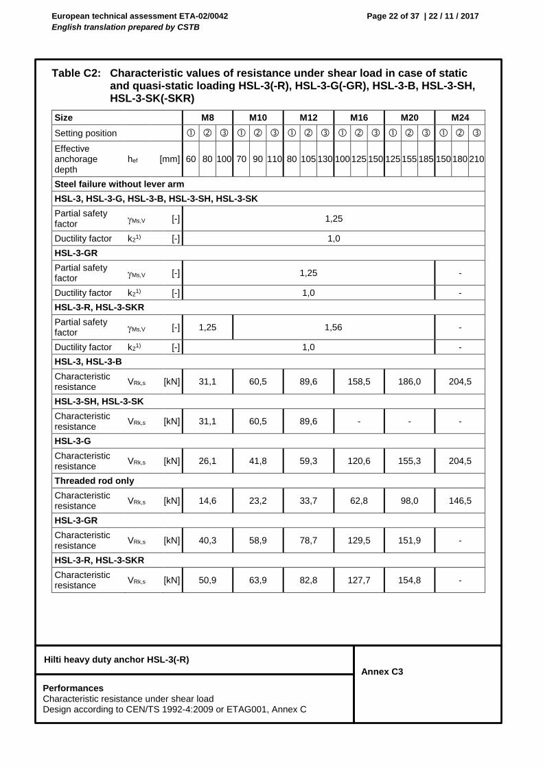
European technical assessment ETA-02/0042
English translation prepared by CSTB
Page 22 of 37 | 22 / 11 / 2017
Hilti heavy duty anchor HSL-3(-R)
Annex C3
Table C2: Characteristic values of resistance under shear load in case of static and quasi-static loading HSL-3(-R), HSL-3-G(-GR), HSL-3-B, HSL-3-SH, HSL-3-SK(-SKR)
Size M8 M10 M12 M16 M20 M24
Setting position
Effective anchorage depth
hef [mm] 60 80 100 70 90 110 80 105 130 100 125 150 125 155 185 150 180 210
Steel failure without lever arm
HSL-3, HSL-3-G, HSL-3-B, HSL-3-SH, HSL-3-SK
Partial safety factor
Ms,V [-] 1,25
Ductility factor k21) [-] 1,0
HSL-3-GR
Partial safety factor
Ms,V [-] 1,25 -
Ductility factor k21) [-] 1,0 -
HSL-3-R, HSL-3-SKR
Partial safety factor
Ms,V [-] 1,25 1,56 -
Ductility factor k21) [-] 1,0 -
HSL-3, HSL-3-B
Characteristic resistance
VRk,s [kN] 31,1 60,5 89,6 158,5 186,0 204,5
HSL-3-SH, HSL-3-SK
Characteristic resistance
VRk,s [kN] 31,1 60,5 89,6 - - -
HSL-3-G
Characteristic resistance
VRk,s [kN] 26,1 41,8 59,3 120,6 155,3 204,5
Threaded rod only
Characteristic resistance
VRk,s [kN] 14,6 23,2 33,7 62,8 98,0 146,5
HSL-3-GR
Characteristic resistance
VRk,s [kN] 40,3 58,9 78,7 129,5 151,9 -
HSL-3-R, HSL-3-SKR
Characteristic resistance
VRk,s [kN] 50,9 63,9 82,8 127,7 154,8 -
Performances Characteristic resistance under shear load Design according to CEN/TS 1992-4:2009 or ETAG001, Annex C
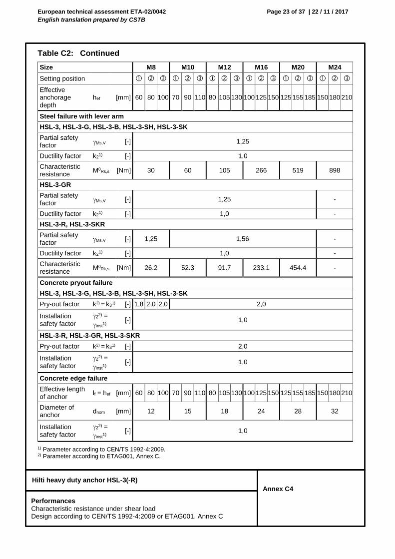
European technical assessment ETA-02/0042
English translation prepared by CSTB
Page 23 of 37 | 22 / 11 / 2017
Hilti heavy duty anchor HSL-3(-R)
Annex C4
Table C2: Continued
1) Parameter according to CEN/TS 1992-4:2009. 2) Parameter according to ETAG001, Annex C.
Size M8 M10 M12 M16 M20 M24
Setting position
Effective anchorage depth
hef [mm] 60 80 100 70 90 110 80 105 130 100 125 150 125 155 185 150 180 210
Steel failure with lever arm
HSL-3, HSL-3-G, HSL-3-B, HSL-3-SH, HSL-3-SK
Partial safety factor
Ms,V [-] 1,25
Ductility factor k21) [-] 1,0
Characteristic resistance
M0Rk,s [Nm] 30 60 105 266 519 898
HSL-3-GR
Partial safety factor
Ms,V [-] 1,25 -
Ductility factor k21) [-] 1,0 -
HSL-3-R, HSL-3-SKR
Partial safety factor
Ms,V [-] 1,25 1,56 -
Ductility factor k21) [-] 1,0 -
Characteristic resistance
M0Rk,s [Nm] 26.2 52.3 91.7 233.1 454.4 -
Concrete pryout failure
HSL-3, HSL-3-G, HSL-3-B, HSL-3-SH, HSL-3-SK
Pry-out factor k2) = k3
1) [-] 1,8 2,0 2,0 2,0
Installation safety factor
22) =
inst1)
[-] 1,0
HSL-3-R, HSL-3-GR, HSL-3-SKR
Pry-out factor k2) = k3
1) [-] 2,0
Installation safety factor
22) =
inst1)
[-] 1,0
Concrete edge failure
Effective length of anchor
lf = hef [mm] 60 80 100 70 90 110 80 105 130 100 125 150 125 155 185 150 180 210
Diameter of anchor
dnom [mm] 12 15 18 24 28 32
Installation safety factor
22) =
inst1)
[-] 1,0
Performances Characteristic resistance under shear load Design according to CEN/TS 1992-4:2009 or ETAG001, Annex C
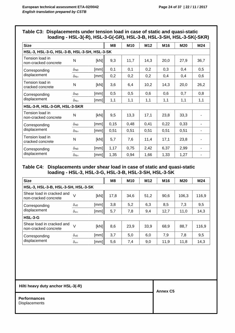
European technical assessment ETA-02/0042
English translation prepared by CSTB
Page 24 of 37 | 22 / 11 / 2017
Hilti heavy duty anchor HSL-3(-R)
Annex C5
Table C3: Displacements under tension load in case of static and quasi-static loading - HSL-3(-R), HSL-3-G(-GR), HSL-3-B, HSL-3-SH, HSL-3-SK(-SKR)
Table C4: Displacements under shear load in case of static and quasi-static loading - HSL-3, HSL-3-G, HSL-3-B, HSL-3-SH, HSL-3-SK
Size M8 M10 M12 M16 M20 M24
HSL-3, HSL-3-G, HSL-3-B, HSL-3-SH, HSL-3-SK
Tension load in non-cracked concrete
N [kN] 9,3 11,7 14,3 20,0 27,9 36,7
Corresponding displacement
N0 [mm] 0,1 0,1 0,2 0,3 0,4 0,5
N [mm] 0,2 0,2 0,2 0,4 0,4 0,6
Tension load in cracked concrete
N [kN] 3,6 6,4 10,2 14,3 20,0 26,2
Corresponding displacement
N0 [mm] 0,5 0,5 0,6 0,6 0,7 0,8
N [mm] 1,1 1,1 1,1 1,1 1,1 1,1
HSL-3-R, HSL-3-GR, HSL-3-SKR
Tension load in non-cracked concrete
N [kN] 9,5 13,3 17,1 23,8 33,3 -
Corresponding displacement
N0 [mm] 0,15 0,48 0,41 0,22 0,33 -
N [mm] 0,51 0,51 0,51 0,51 0,51 -
Tension load in cracked concrete
N [kN] 5,7 7,6 11,4 17,1 23,8 -
Corresponding displacement
N0 [mm] 1,17 0,75 2,42 6,37 2,99 -
N [mm] 1,35 0,94 1,66 1,33 1,27 -
Size M8 M10 M12 M16 M20 M24
HSL-3, HSL-3-B, HSL-3-SH, HSL-3-SK
Shear load in cracked and non-cracked concrete
V [kN] 17,8 34,6 51,2 90,6 106,3 116,9
Corresponding displacement
v0 [mm] 3,8 5,2 6,3 8,5 7,3 9,5
v [mm] 5,7 7,8 9,4 12,7 11,0 14,3
HSL-3-G
Shear load in cracked and non-cracked concrete
V [kN] 8,6 23,9 33,9 68,9 88,7 116,9
Corresponding displacement
v0 [mm] 3,7 5,0 6,0 7,9 7,8 9,5
v [mm] 5,6 7,4 9,0 11,9 11,8 14,3
Performances Displacements
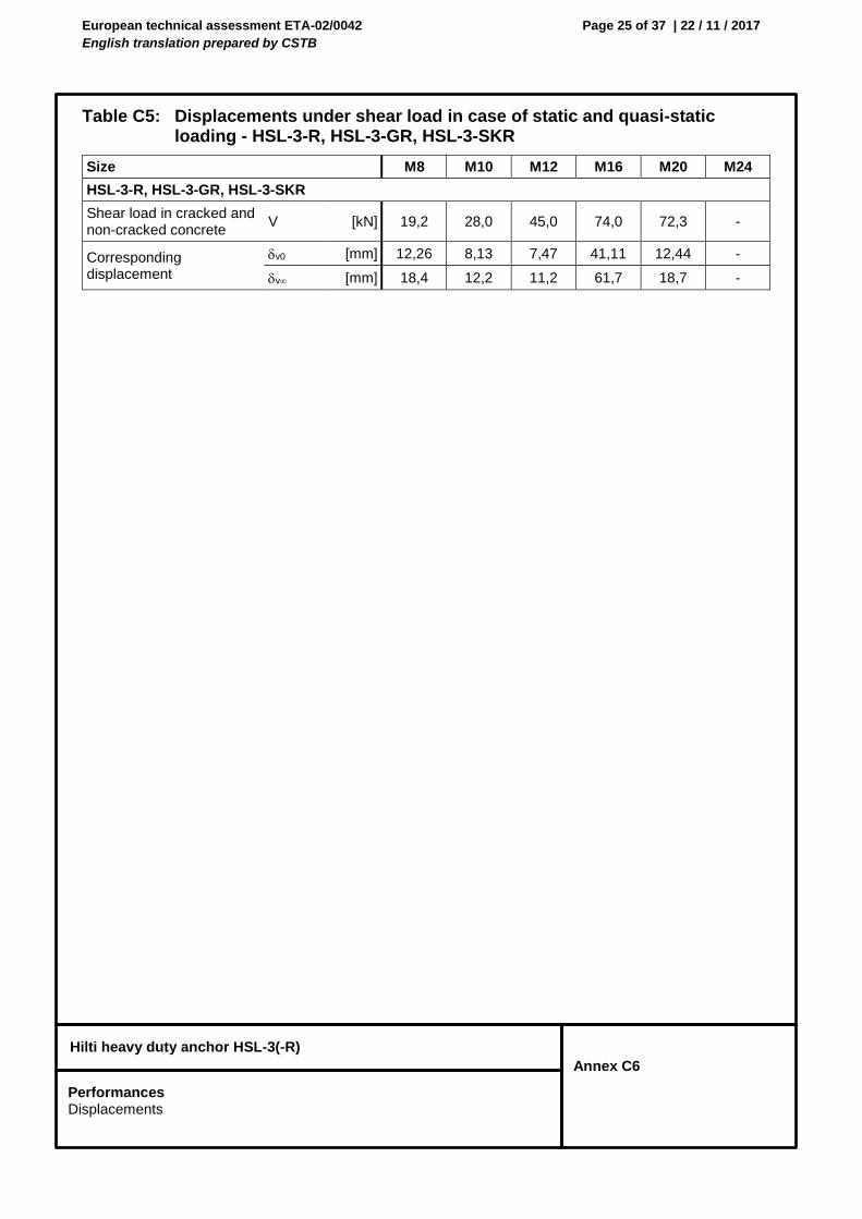
European technical assessment ETA-02/0042
English translation prepared by CSTB
Page 25 of 37 | 22 / 11 / 2017
Hilti heavy duty anchor HSL-3(-R)
Annex C6
Table C5: Displacements under shear load in case of static and quasi-static loading - HSL-3-R, HSL-3-GR, HSL-3-SKR
Size M8 M10 M12 M16 M20 M24
HSL-3-R, HSL-3-GR, HSL-3-SKR
Shear load in cracked and non-cracked concrete
V [kN] 19,2 28,0 45,0 74,0 72,3 -
Corresponding displacement
v0 [mm] 12,26 8,13 7,47 41,11 12,44 -
v [mm] 18,4 12,2 11,2 61,7 18,7 -
Performances Displacements
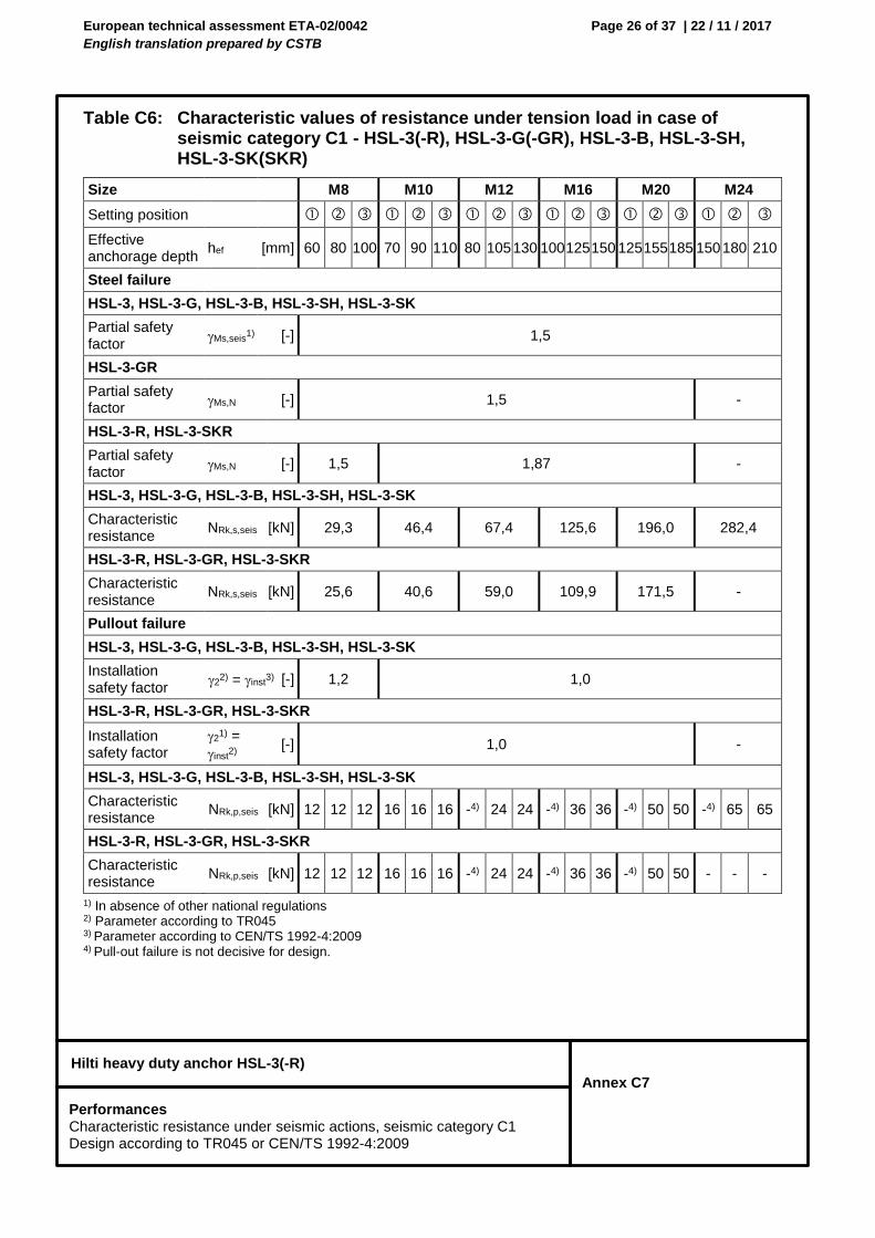
European technical assessment ETA-02/0042
English translation prepared by CSTB
Page 26 of 37 | 22 / 11 / 2017
Hilti heavy duty anchor HSL-3(-R)
Annex C7
Table C6: Characteristic values of resistance under tension load in case of seismic category C1 - HSL-3(-R), HSL-3-G(-GR), HSL-3-B, HSL-3-SH, HSL-3-SK(SKR)
1) In absence of other national regulations 2) Parameter according to TR045 3) Parameter according to CEN/TS 1992-4:2009 4) Pull-out failure is not decisive for design.
Size M8 M10 M12 M16 M20 M24
Setting position
Effective anchorage depth
hef [mm] 60 80 100 70 90 110 80 105 130 100 125 150 125 155 185 150 180 210
Steel failure
HSL-3, HSL-3-G, HSL-3-B, HSL-3-SH, HSL-3-SK
Partial safety factor
Ms,seis1) [-] 1,5
HSL-3-GR
Partial safety factor
Ms,N [-] 1,5 -
HSL-3-R, HSL-3-SKR
Partial safety factor
Ms,N [-] 1,5 1,87 -
HSL-3, HSL-3-G, HSL-3-B, HSL-3-SH, HSL-3-SK
Characteristic resistance
NRk,s,seis [kN] 29,3 46,4 67,4 125,6 196,0 282,4
HSL-3-R, HSL-3-GR, HSL-3-SKR
Characteristic resistance
NRk,s,seis [kN] 25,6 40,6 59,0 109,9 171,5 -
Pullout failure
HSL-3, HSL-3-G, HSL-3-B, HSL-3-SH, HSL-3-SK
Installation safety factor
22) = inst
3) [-] 1,2 1,0
HSL-3-R, HSL-3-GR, HSL-3-SKR
Installation safety factor
21) =
inst2)
[-] 1,0 -
HSL-3, HSL-3-G, HSL-3-B, HSL-3-SH, HSL-3-SK
Characteristic resistance
NRk,p,seis [kN] 12 12 12 16 16 16 -4) 24 24 -4) 36 36 -4) 50 50 -4) 65 65
HSL-3-R, HSL-3-GR, HSL-3-SKR
Characteristic resistance
NRk,p,seis [kN] 12 12 12 16 16 16 -4) 24 24 -4) 36 36 -4) 50 50 - - -
Performances Characteristic resistance under seismic actions, seismic category C1 Design according to TR045 or CEN/TS 1992-4:2009
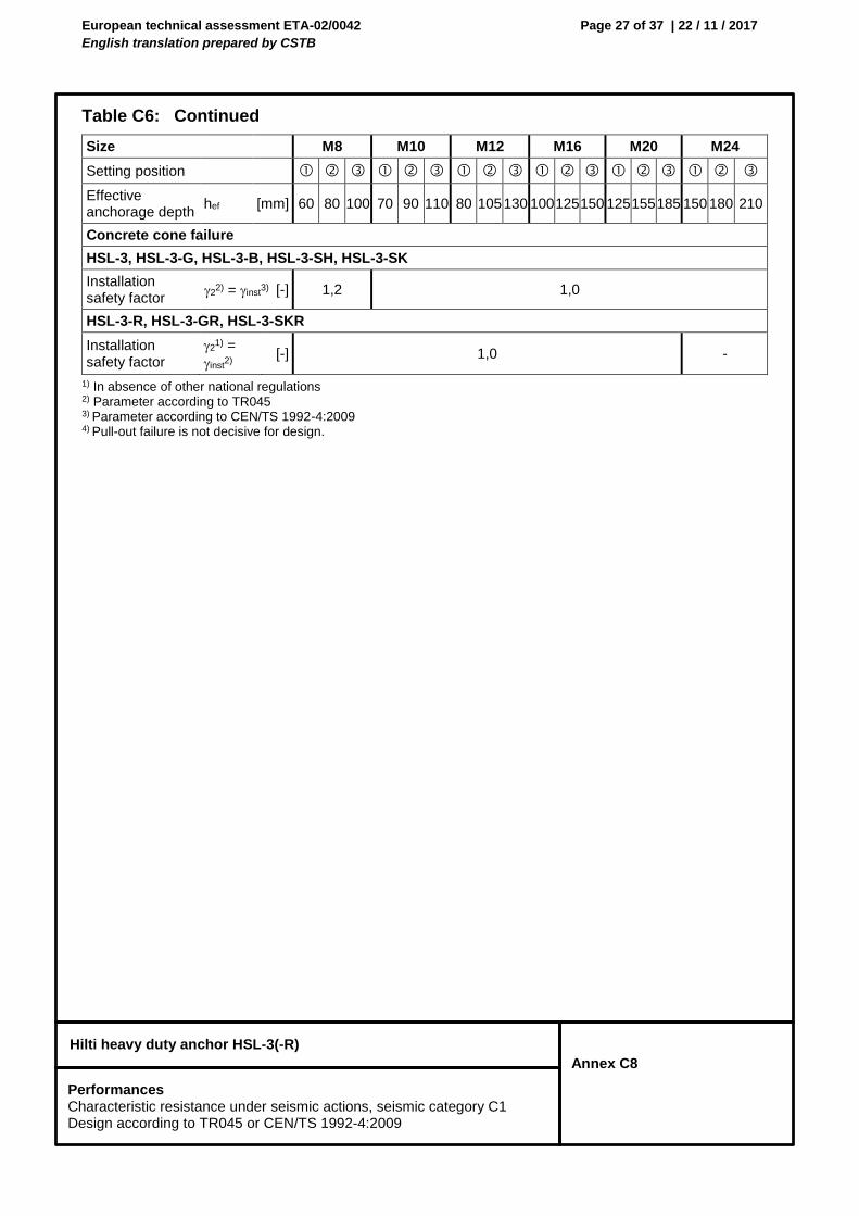
European technical assessment ETA-02/0042
English translation prepared by CSTB
Page 27 of 37 | 22 / 11 / 2017
Hilti heavy duty anchor HSL-3(-R)
Annex C8
Table C6: Continued
1) In absence of other national regulations 2) Parameter according to TR045 3) Parameter according to CEN/TS 1992-4:2009 4) Pull-out failure is not decisive for design.
Size M8 M10 M12 M16 M20 M24
Setting position
Effective anchorage depth
hef [mm] 60 80 100 70 90 110 80 105 130 100 125 150 125 155 185 150 180 210
Concrete cone failure
HSL-3, HSL-3-G, HSL-3-B, HSL-3-SH, HSL-3-SK
Installation safety factor
22) = inst
3) [-] 1,2 1,0
HSL-3-R, HSL-3-GR, HSL-3-SKR
Installation safety factor
21) =
inst2)
[-] 1,0 -
Performances Characteristic resistance under seismic actions, seismic category C1 Design according to TR045 or CEN/TS 1992-4:2009
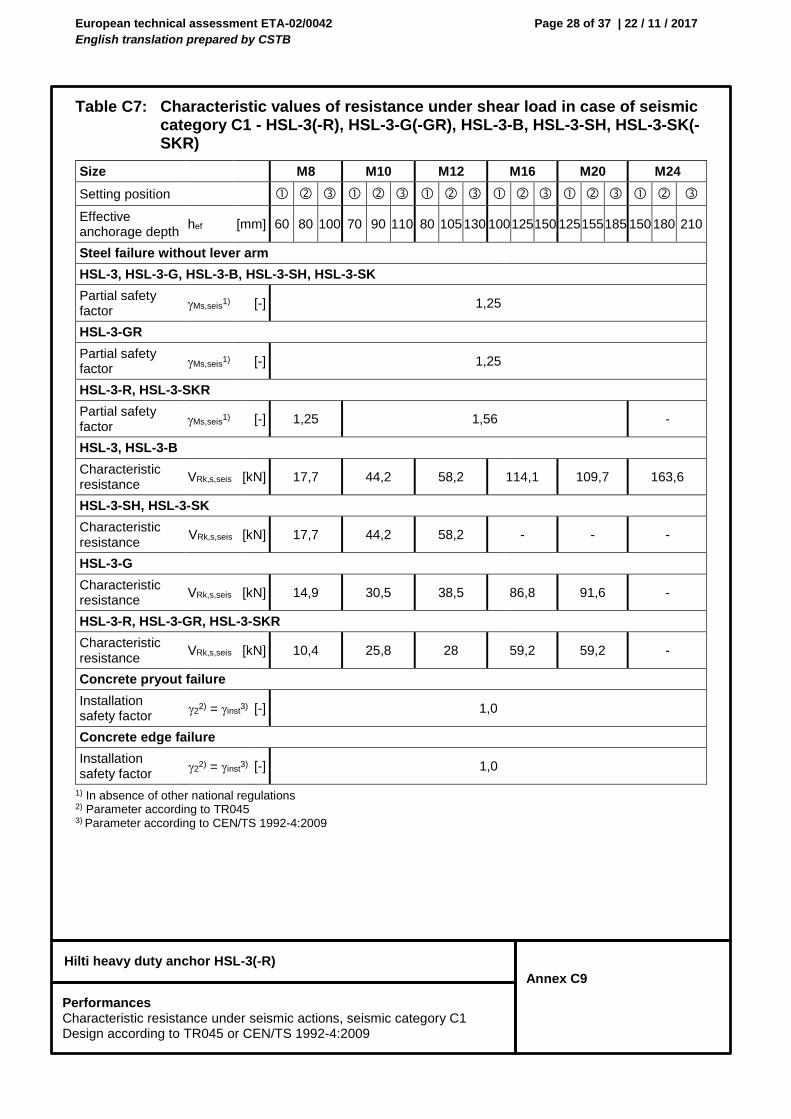
European technical assessment ETA-02/0042
English translation prepared by CSTB
Page 28 of 37 | 22 / 11 / 2017
Hilti heavy duty anchor HSL-3(-R)
Annex C9
Table C7: Characteristic values of resistance under shear load in case of seismic category C1 - HSL-3(-R), HSL-3-G(-GR), HSL-3-B, HSL-3-SH, HSL-3-SK(-SKR)
1) In absence of other national regulations 2) Parameter according to TR045 3) Parameter according to CEN/TS 1992-4:2009
Size M8 M10 M12 M16 M20 M24
Setting position
Effective anchorage depth
hef [mm] 60 80 100 70 90 110 80 105 130 100 125 150 125 155 185 150 180 210
Steel failure without lever arm
HSL-3, HSL-3-G, HSL-3-B, HSL-3-SH, HSL-3-SK
Partial safety factor
Ms,seis1) [-] 1,25
HSL-3-GR
Partial safety factor
Ms,seis1) [-] 1,25
HSL-3-R, HSL-3-SKR
Partial safety factor
Ms,seis1) [-] 1,25 1,56 -
HSL-3, HSL-3-B
Characteristic resistance
VRk,s,seis [kN] 17,7 44,2 58,2 114,1 109,7 163,6
HSL-3-SH, HSL-3-SK
Characteristic resistance
VRk,s,seis [kN] 17,7 44,2 58,2 - - -
HSL-3-G
Characteristic resistance
VRk,s,seis [kN] 14,9 30,5 38,5 86,8 91,6 -
HSL-3-R, HSL-3-GR, HSL-3-SKR
Characteristic resistance
VRk,s,seis [kN] 10,4 25,8 28 59,2 59,2 -
Concrete pryout failure
Installation safety factor
22) = inst
3) [-] 1,0
Concrete edge failure
Installation safety factor
22) = inst
3) [-] 1,0
Performances Characteristic resistance under seismic actions, seismic category C1 Design according to TR045 or CEN/TS 1992-4:2009
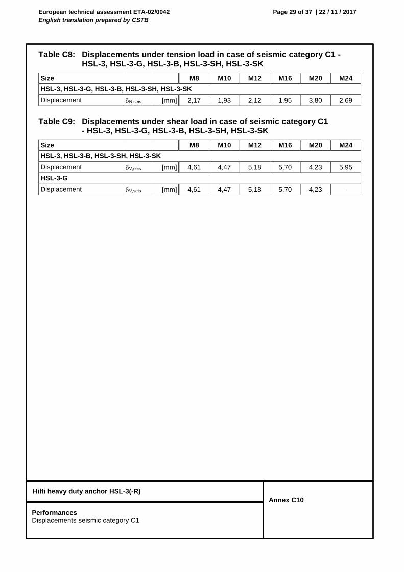
European technical assessment ETA-02/0042
English translation prepared by CSTB
Page 29 of 37 | 22 / 11 / 2017
Hilti heavy duty anchor HSL-3(-R)
Annex C10
Table C8: Displacements under tension load in case of seismic category C1 - HSL-3, HSL-3-G, HSL-3-B, HSL-3-SH, HSL-3-SK
Table C9: Displacements under shear load in case of seismic category C1 - HSL-3, HSL-3-G, HSL-3-B, HSL-3-SH, HSL-3-SK
Size M8 M10 M12 M16 M20 M24
HSL-3, HSL-3-G, HSL-3-B, HSL-3-SH, HSL-3-SK
Displacement N,seis [mm] 2,17 1,93 2,12 1,95 3,80 2,69
Size M8 M10 M12 M16 M20 M24
HSL-3, HSL-3-B, HSL-3-SH, HSL-3-SK
Displacement V,seis [mm] 4,61 4,47 5,18 5,70 4,23 5,95
HSL-3-G
Displacement V,seis [mm] 4,61 4,47 5,18 5,70 4,23 -
Performances Displacements seismic category C1
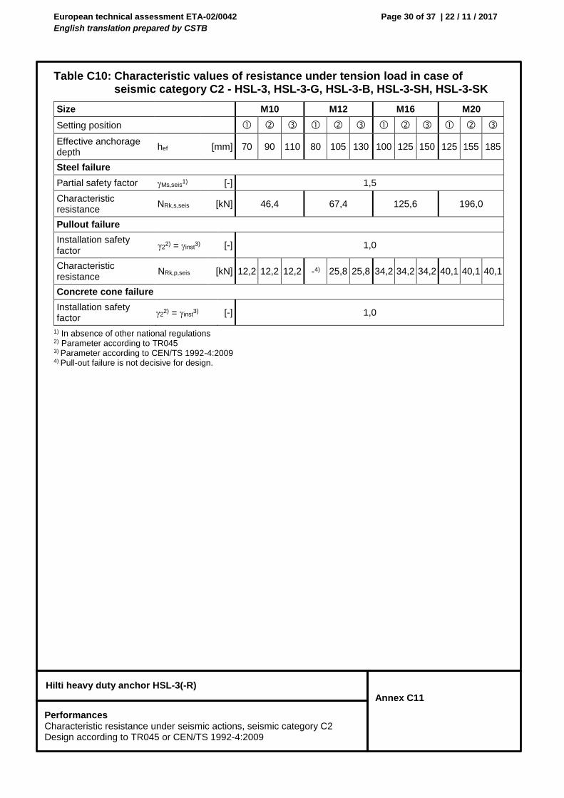
European technical assessment ETA-02/0042
English translation prepared by CSTB
Page 30 of 37 | 22 / 11 / 2017
Hilti heavy duty anchor HSL-3(-R)
Annex C11
Table C10: Characteristic values of resistance under tension load in case of seismic category C2 - HSL-3, HSL-3-G, HSL-3-B, HSL-3-SH, HSL-3-SK
1) In absence of other national regulations 2) Parameter according to TR045 3) Parameter according to CEN/TS 1992-4:2009 4) Pull-out failure is not decisive for design.
Size M10 M12 M16 M20
Setting position
Effective anchorage depth
hef [mm] 70 90 110 80 105 130 100 125 150 125 155 185
Steel failure
Partial safety factor Ms,seis1) [-] 1,5
Characteristic resistance
NRk,s,seis [kN] 46,4 67,4 125,6 196,0
Pullout failure
Installation safety factor
22) = inst
3) [-] 1,0
Characteristic resistance
NRk,p,seis [kN] 12,2 12,2 12,2 -4) 25,8 25,8 34,2 34,2 34,2 40,1 40,1 40,1
Concrete cone failure
Installation safety factor
22) = inst
3) [-] 1,0
Performances Characteristic resistance under seismic actions, seismic category C2 Design according to TR045 or CEN/TS 1992-4:2009
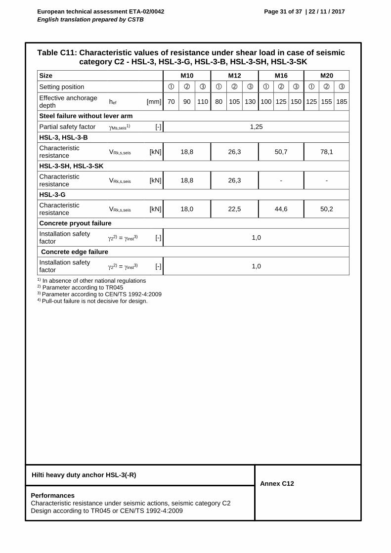
European technical assessment ETA-02/0042
English translation prepared by CSTB
Page 31 of 37 | 22 / 11 / 2017
Hilti heavy duty anchor HSL-3(-R)
Annex C12
Table C11: Characteristic values of resistance under shear load in case of seismic category C2 - HSL-3, HSL-3-G, HSL-3-B, HSL-3-SH, HSL-3-SK
1) In absence of other national regulations 2) Parameter according to TR045 3) Parameter according to CEN/TS 1992-4:2009 4) Pull-out failure is not decisive for design.
Size M10 M12 M16 M20
Setting position
Effective anchorage depth
hef [mm] 70 90 110 80 105 130 100 125 150 125 155 185
Steel failure without lever arm
Partial safety factor Ms,seis1) [-] 1,25
HSL-3, HSL-3-B
Characteristic resistance
VRk,s,seis [kN] 18,8 26,3 50,7 78,1
HSL-3-SH, HSL-3-SK
Characteristic resistance
VRk,s,seis [kN] 18,8 26,3 - -
HSL-3-G
Characteristic resistance
VRk,s,seis [kN] 18,0 22,5 44,6 50,2
Concrete pryout failure
Installation safety factor
22) = inst
3) [-] 1,0
Concrete edge failure
Installation safety factor
22) = inst
3) [-] 1,0
Performances Characteristic resistance under seismic actions, seismic category C2 Design according to TR045 or CEN/TS 1992-4:2009
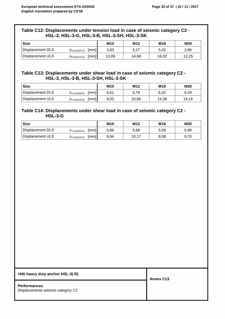
European technical assessment ETA-02/0042
English translation prepared by CSTB
Page 32 of 37 | 22 / 11 / 2017
Hilti heavy duty anchor HSL-3(-R)
Annex C13
Table C12: Displacements under tension load in case of seismic category C2 - HSL-3, HSL-3-G, HSL-3-B, HSL-3-SH, HSL-3-SK
Size M10 M12 M16 M20
Displacement DLS N,seis(DLS) [mm] 3,63 5,27 5,42 3,95
Displacement ULS N,seis(ULS) [mm] 13,09 14,68 16,02 12,25
Table C13: Displacements under shear load in case of seismic category C2 - HSL-3, HSL-3-B, HSL-3-SH, HSL-3-SK
Size M10 M12 M16 M20
Displacement DLS V,seis(DLS) [mm] 5,61 5,79 6,32 6,29
Displacement ULS V,seis(ULS) [mm] 9,03 10,66 14,38 14,16
Table C14: Displacements under shear load in case of seismic category C2 - HSL-3-G
Size M10 M12 M16 M20
Displacement DLS V,seis(DLS) [mm] 5,86 5,68 5,58 5,88
Displacement ULS V,seis(ULS) [mm] 9,94 10,17 9,08 9,70
Performances Displacements seismic category C2
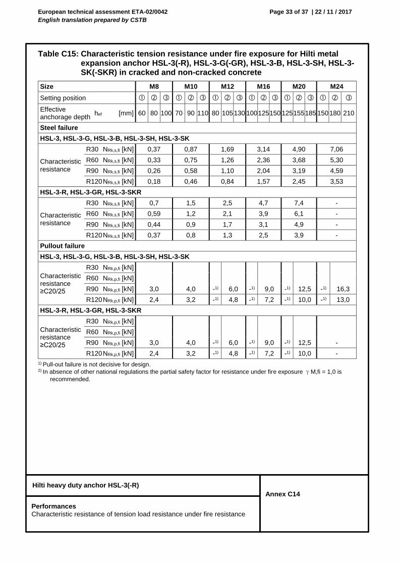
European technical assessment ETA-02/0042
English translation prepared by CSTB
Page 33 of 37 | 22 / 11 / 2017
Hilti heavy duty anchor HSL-3(-R)
Annex C14
Table C15: Characteristic tension resistance under fire exposure for Hilti metal expansion anchor HSL-3(-R), HSL-3-G(-GR), HSL-3-B, HSL-3-SH, HSL-3-SK(-SKR) in cracked and non-cracked concrete
1) Pull-out failure is not decisive for design. 2) In absence of other national regulations the partial safety factor for resistance under fire exposure γM,fi = 1,0 is
recommended.
Size M8 M10 M12 M16 M20 M24
Setting position
Effective anchorage depth
hef [mm] 60 80 100 70 90 110 80 105 130 100 125 150 125 155 185 150 180 210
Steel failure
HSL-3, HSL-3-G, HSL-3-B, HSL-3-SH, HSL-3-SK
Characteristic resistance
R30 NRk,s,fi [kN] 0,37 0,87 1,69 3,14 4,90 7,06
R60 NRk,s,fi [kN] 0,33 0,75 1,26 2,36 3,68 5,30
R90 NRk,s,fi [kN] 0,26 0,58 1,10 2,04 3,19 4,59
R120 NRk,s,fi [kN] 0,18 0,46 0,84 1,57 2,45 3,53
HSL-3-R, HSL-3-GR, HSL-3-SKR
Characteristic resistance
R30 NRk,s,fi [kN] 0,7 1,5 2,5 4,7 7,4 -
R60 NRk,s,fi [kN] 0,59 1,2 2,1 3,9 6,1 -
R90 NRk,s,fi [kN] 0,44 0,9 1,7 3,1 4,9 -
R120 NRk,s,fi [kN] 0,37 0,8 1,3 2,5 3,9 -
Pullout failure
HSL-3, HSL-3-G, HSL-3-B, HSL-3-SH, HSL-3-SK
Characteristic resistance ≥C20/25
R30 NRk,p,fi [kN]
3,0 4,0 -1) 6,0 -1) 9,0 -1) 12,5 -1) 16,3
R60 NRk,p,fi [kN]
R90 NRk,p,fi [kN]
R120 NRk,p,fi [kN] 2,4 3,2 -1) 4,8 -1) 7,2 -1) 10,0 -1) 13,0
HSL-3-R, HSL-3-GR, HSL-3-SKR
Characteristic resistance ≥C20/25
R30 NRk,p,fi [kN]
3,0 4,0 -1) 6,0 -1) 9,0 -1) 12,5 -
R60 NRk,p,fi [kN]
R90 NRk,p,fi [kN]
R120 NRk,p,fi [kN] 2,4 3,2 -1) 4,8 -1) 7,2 -1) 10,0 -
Performances Characteristic resistance of tension load resistance under fire resistance
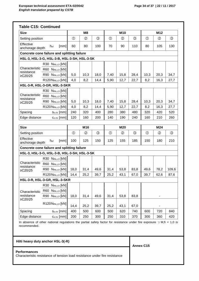
European technical assessment ETA-02/0042
English translation prepared by CSTB
Page 34 of 37 | 22 / 11 / 2017
Hilti heavy duty anchor HSL-3(-R)
Annex C15
Table C15: Continued
In absence of other national regulations the partial safety factor for resistance under fire exposure γM,fi = 1,0 is
recommended.
Size M8 M10 M12
Setting position
Effective anchorage depth
hef [mm] 60 80 100 70 90 110 80 105 130
Concrete cone failure and splitting failure
HSL-3, HSL-3-G, HSL-3-B, HSL-3-SH, HSL-3-SK
Characteristic resistance ≥C20/25
R30 NRk,c,fi [kN]
5,0 10,3 18,0 7,40 15,8 28,4 10,3 20,3 34,7
R60 NRk,c,fi [kN]
R90 NRk,c,fi [kN]
R120 NRk,c,fi [kN] 4,0 8,2 14,4 5,90 12,7 22,7 8,2 16,3 27,7
HSL-3-R, HSL-3-GR, HSL-3-SKR
Characteristic resistance ≥C20/25
R30 NRk,c,fi [kN]
5,0 10,3 18,0 7,40 15,8 28,4 10,3 20,3 34,7
R60 NRk,c,fi [kN]
R90 NRk,c,fi [kN]
R120 NRk,c,fi [kN] 4,0 8,2 14,4 5,90 12,7 22,7 8,2 16,3 27,7
Spacing scr,N [mm] 240 320 400 280 380 480 320 420 520
Edge distance ccr,N [mm] 120 160 200 140 190 240 160 210 260
Size M16 M20 M24
Setting position
Effective anchorage depth
hef [mm] 100 125 150 125 155 185 150 180 210
Concrete cone failure and splitting failure
HSL-3, HSL-3-G, HSL-3-B, HSL-3-SH, HSL-3-SK
Characteristic resistance ≥C20/25
R30 NRk,c,fi [kN]
18,0 31,4 49,6 31,4 53,8 83,8 49,6 78,2 109,6
R60 NRk,c,fi [kN]
R90 NRk,c,fi [kN]
R120 NRk,c,fi [kN] 14,4 25,2 39,7 25,2 43,1 67,0 39,7 62,6 87,6
HSL-3-R, HSL-3-GR, HSL-3-SKR
Characteristic resistance ≥C20/25
R30 NRk,c,fi [kN]
18,0 31,4 49,6 31,4 53,8 83,8
-
R60 NRk,c,fi [kN]
R90 NRk,c,fi [kN]
R120 NRk,c,fi [kN] 14,4 25,2 39,7 25,2 43,1 67,0
-
Spacing scr,N [mm] 400 500 600 500 620 740 600 720 840
Edge distance ccr,N [mm] 200 250 300 250 310 370 300 360 420
Performances Characteristic resistance of tension load resistance under fire resistance
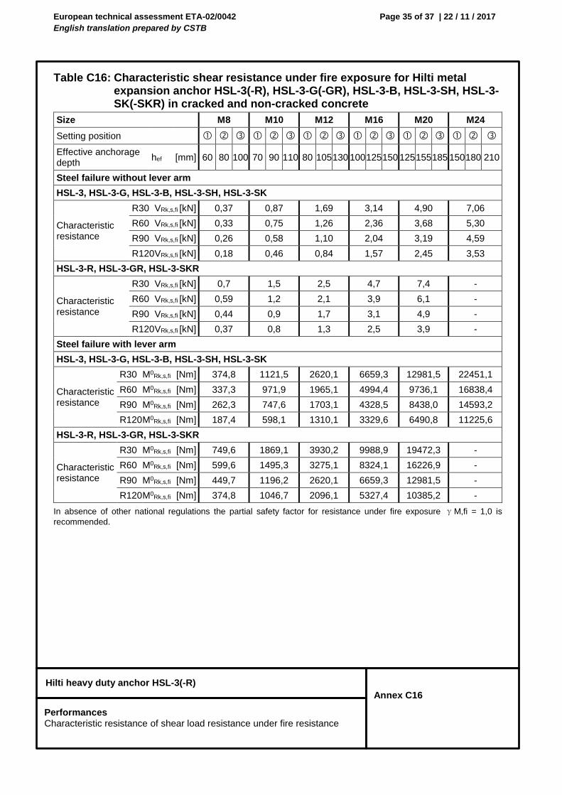
European technical assessment ETA-02/0042
English translation prepared by CSTB
Page 35 of 37 | 22 / 11 / 2017
Hilti heavy duty anchor HSL-3(-R)
Annex C16
Table C16: Characteristic shear resistance under fire exposure for Hilti metal expansion anchor HSL-3(-R), HSL-3-G(-GR), HSL-3-B, HSL-3-SH, HSL-3-SK(-SKR) in cracked and non-cracked concrete
In absence of other national regulations the partial safety factor for resistance under fire exposure γM,fi = 1,0 is
recommended.
Size M8 M10 M12 M16 M20 M24
Setting position
Effective anchorage depth
hef [mm] 60 80 100 70 90 110 80 105 130 100 125 150 125 155 185 150 180 210
Steel failure without lever arm
HSL-3, HSL-3-G, HSL-3-B, HSL-3-SH, HSL-3-SK
Characteristic resistance
R30 VRk,s,fi [kN] 0,37 0,87 1,69 3,14 4,90 7,06
R60 VRk,s,fi [kN] 0,33 0,75 1,26 2,36 3,68 5,30
R90 VRk,s,fi [kN] 0,26 0,58 1,10 2,04 3,19 4,59
R120 VRk,s,fi [kN] 0,18 0,46 0,84 1,57 2,45 3,53
HSL-3-R, HSL-3-GR, HSL-3-SKR
Characteristic resistance
R30 VRk,s,fi [kN] 0,7 1,5 2,5 4,7 7,4 -
R60 VRk,s,fi [kN] 0,59 1,2 2,1 3,9 6,1 -
R90 VRk,s,fi [kN] 0,44 0,9 1,7 3,1 4,9 -
R120 VRk,s,fi [kN] 0,37 0,8 1,3 2,5 3,9 -
Steel failure with lever arm
HSL-3, HSL-3-G, HSL-3-B, HSL-3-SH, HSL-3-SK
Characteristic resistance
R30 M0Rk,s,fi [Nm] 374,8 1121,5 2620,1 6659,3 12981,5 22451,1
R60 M0Rk,s,fi [Nm] 337,3 971,9 1965,1 4994,4 9736,1 16838,4
R90 M0Rk,s,fi [Nm] 262,3 747,6 1703,1 4328,5 8438,0 14593,2
R120 M0Rk,s,fi [Nm] 187,4 598,1 1310,1 3329,6 6490,8 11225,6
HSL-3-R, HSL-3-GR, HSL-3-SKR
Characteristic resistance
R30 M0Rk,s,fi [Nm] 749,6 1869,1 3930,2 9988,9 19472,3 -
R60 M0Rk,s,fi [Nm] 599,6 1495,3 3275,1 8324,1 16226,9 -
R90 M0Rk,s,fi [Nm] 449,7 1196,2 2620,1 6659,3 12981,5 -
R120 M0Rk,s,fi [Nm] 374,8 1046,7 2096,1 5327,4 10385,2 -
Performances Characteristic resistance of shear load resistance under fire resistance

European technical assessment ETA-02/0042
English translation prepared by CSTB
Page 36 of 37 | 22 / 11 / 2017
Hilti heavy duty anchor HSL-3(-R)
Annex C17
Table C16: Continued
In absence of other national regulations the partial safety factor for resistance under fire exposure γM,fi = 1,0 is
recommended.
Size M8 M10 M12
Setting position
Effective anchorage depth
hef [mm] 60 80 100 70 90 110 80 105 130
Concrete pryout failure
Factor in equation (5.6) of ETAG 001
Annex C, 5.2.3.3 k [-] 2,0
HSL-3, HSL-3-G, HSL-3-B, HSL-3-SH, HSL-3-SK
Characteristic resistance ≥C20/25
R30 VRk,cp,fi [kN]
10,0 20,6 36,0 14,8 31,7 56,8 20,6 40,7 69,4
R60 VRk,cp,fi [kN]
R90 VRk,cp,fi [kN]
R120 VRk,cp,fi [kN] 8,00 16,5 28,8 11,8 25,3 45,4 16,5 32,5 55,5
HSL-3-R, HSL-3-GR, HSL-3-SKR
Characteristic resistance ≥C20/25
R30 VRk,cp,fi [kN]
10,0 20,6 36,0 14,8 31,7 56,8 20,6 40,7 69,4
R60 VRk,cp,fi [kN]
R90 VRk,cp,fi [kN]
R120 VRk,cp,fi [kN] 8,00 16,5 28,8 11,8 25,3 45,4 16,5 32,5 55,5
Concrete edge failure
The initial value V0Rk,c,fi of the characteristic resistance in concrete C20/25 to C50/60 under fire exposure may be determined by:
V0Rk,c,fi = 0,25 x V0Rk,c (≤ R90) V0Rk,c,fi = 0,20 x V0Rk,c (R120) with V0Rk,c,fi initial value of the characteristic resistance in cracked concrete C20/25 under normal temperature.
Performances Characteristic resistance of shear load resistance under fire resistance

European technical assessment ETA-02/0042
English translation prepared by CSTB
Page 37 of 37 | 22 / 11 / 2017
Hilti heavy duty anchor HSL-3(-R)
Annex C18
Table C16: Continued
In absence of other national regulations the partial safety factor for resistance under fire exposure γM,fi = 1,0 is
recommended.
Size M16 M20 M24
Setting position
Effective anchorage depth
hef [mm] 100 125 150 125 155 185 150 180 210
Concrete pryout failure
Factor in equation (5.6) of ETAG 001
Annex C, 5.2.3.3 k [-] 2,0
HSL-3, HSL-3-G, HSL-3-B, HSL-3-SH, HSL-3-SK
Characteristic resistance ≥C20/25
R30 VRk,cp,fi [kN]
36,0 62,9 99,2 62,9 107,7 167,6 99,2 156,5 219,1
R60 VRk,cp,fi [kN]
R90 VRk,cp,fi [kN]
R120 VRk,cp,fi [kN] 28,8 50,3 79,4 50,3 86,1 134,1 79,4 125,2 175,3
HSL-3-R, HSL-3-GR, HSL-3-SKR
Characteristic resistance ≥C20/25
R30 VRk,cp,fi [kN]
36,0 62,9 99,2 62,9 107,7 167,6 - - -
R60 VRk,cp,fi [kN]
R90 VRk,cp,fi [kN]
R120 VRk,cp,fi [kN] 28,8 50,3 79,4 50,3 86,1 134,1 - - -
Concrete edge failure
The initial value V0Rk,c,fi of the characteristic resistance in concrete C20/25 to C50/60 under fire exposure may be determined by:
V0Rk,c,fi = 0,25 x V0Rk,c (≤ R90) V0Rk,c,fi = 0,20 x V0Rk,c (R120) with V0Rk,c,fi initial value of the characteristic resistance in cracked concrete C20/25 under normal temperature.
Performances Characteristic resistance of shear load resistance under fire resistance