Embed Size (px)
Citation preview

Hilti HIT-RE 500 with HIT-V / HAS in hammer drilled holes
09 / 2012
424
Hilti HIT-RE 500 with HIT-V / HAS
in hammer drilled holes
Injection mortar system Benefits
Hilti HIT-RE 500 330 ml foil pack
(also available as 500 ml and 1400 ml foil pack)
- suitable for non-cracked concrete C 20/25 to C 50/60
- high loading capacity - suitable for dry and water
saturated concrete
- under water application - large diameter applications
- high corrosion resistant - long working time at elevated
temperatures - odourless epoxy
- embedment depth range: from 40 … 160 mm for M8 to 120 … 600 mm for M30
Statik mixer
HAS rod
HAS-E rod
HIT-V rod
Concrete Small edge distance
and spacing
Variable embedment
depth
Fire resistance
Corrosion resistance
High corrosion resistance
European Technical Approval
CE conformity
PROFIS Anchor design software
Approvals / certificates Description Authority / Laboratory No. / date of issue European technical approval a) DIBt, Berlin ETA-04/0027 / 2009-05-20
Fire test report IBMB, Braunschweig UB 3565 / 4595 / 2006-10-29 UB 3588 / 4825 / 2005-11-15
Assessment report (fire) warringtonfire WF 166402 / 2007-10-26 & suppl. WF 172920 / 2008-05-27
a) All data given in this section according ETA-04/0027, issue 2009-05-20.

Hilti HIT-RE 500 with HIT-V / HAS
in hammer drilled holes
09 / 2012
425
Basic loading data (for a single anchor) All data in this section applies to For details see Simplified design method - Correct setting (See setting instruction) - No edge distance and spacing influence - Steel failure - Base material thickness, as specified in the table - One typical embedment depth, as specified in the table - One anchor material, as specified in the tables - Concrete C 20/25, fck,cube = 25 N/mm² - Temperature range I
(min. base material temperature -40°C, max. long ter m/short term base material temperature: +24°C/40°C) - Installation temperature range +5°C to +40°C Embedment depth a) and base material thickness for the basic loading d ata. Mean ultimate resistance, characteristic resistance , design resistance, recommended loads. Anchor size M8 M10 M12 M16 M20 M24 M27 M30 M33 M36 M39 Typical embedment depth [mm] 80 90 110 125 170 210 240 270 300 330 360 Base material thickness [mm] 110 120 140 165 220 270 300 340 380 410 450
a) The allowed range of embedment depth is shown in the setting details. The corresponding load values can be calculated according to the simplified design method.
Mean ultimate resistance: concrete C 20/25 – fck,cube = 25 N/mm², anchor HIT -V 5.8 Data according ETA-04/0027, issue 2008-11-03 Additional Hilti
technical data Anchor size M8 M10 M12 M16 M20 M24 M27 M30 M33 M36 M39
Tensile NRu,m HIT-V 5.8 [kN] 18,9 30,5 44,1 83,0 129,2 185,9 241,5 295,1 364,4 428,9 459,9
Shear VRu,m HIT-V 5.8 [kN] 9,5 15,8 22,1 41,0 64,1 92,4 120,8 147,0 182,2 214,5 256,2
Characteristic resistance: concrete C 20/25 – fck,cube = 25 N/mm², anchor HIT -V 5.8 Data according ETA-04/0027, issue 2008-11-03 Additional Hilti
technical data Anchor size M8 M10 M12 M16 M20 M24 M27 M30 M33 M36 M39
Tensile NRk HIT-V 5.8 [kN] 18,0 29,0 42,0 70,6 111,9 153,7 187,8 224,0 262,4 302,7 344,9
Shear VRk HIT-V 5.8 [kN] 9,0 15,0 21,0 39,0 61,0 88,0 115,0 140,0 173,5 204,3 244,0
Design resistance: concrete C 20/25 – fck,cube = 25 N/mm², anchor H IT-V 5.8 Data according ETA-04/0027, issue 2008-11-03 Additional Hilti
technical data Anchor size M8 M10 M12 M16 M20 M24 M27 M30 M33 M36 M39
Tensile NRd HIT-V 5.8 [kN] 12,0 19,3 27,7 33,6 53,3 73,2 89,4 106,7 125,0 144,2 164,3
Shear VRd HIT-V 5.8 [kN] 7,2 12,0 16,8 31,2 48,8 70,4 92,0 112,0 138,8 163,4 195,2 Recommended loads a): concrete C 20/25 – fck,cube = 25 N/mm², anchor HIT -V 5.8 Data according ETA-04/0027, issue 2008-11-03 Additional Hilti
technical data Anchor size M8 M10 M12 M16 M20 M24 M27 M30 M33 M36 M39
Tensile Nrec HIT-V 5.8 [kN] 8,6 13,8 19,8 24,0 38,1 52,3 63,9 76,2 89,3 103,0 117,3
Shear Vrec HIT-V 5.8 [kN] 5,1 8,6 12,0 22,3 34,9 50,3 65,7 80,0 99,1 116,7 139,4
a) With overall partial safety factor for action γ = 1,4. The partial safety factors for action depend on the type of loading and shall be taken from national regulations.

Hilti HIT-RE 500 with HIT-V / HAS in hammer drilled holes
09 / 2012
426
Service temperature range Hilti HIT-RE 500 injection mortar may be applied in the temperature ranges given below. An elevated base material temperature may lead to a reduction of the design bond resistance.
Temperature range Base material temperature
Maximum long term base material temperature
Maximum short term base material temperature
Temperature range I -40 °C to +40 °C +24 °C +40 °C Temperature range II -40 °C to +58 °C +35 °C +58 °C Temperature range III -40 °C to +70 °C +43 °C +70 ° C
Max short term base material temperature Short-term elevated base material temperatures are those that occur over brief intervals, e.g. as a result of diurnal cycling.
Max long term base material temperature Long-term elevated base material temperatures are roughly constant over significant periods of time. Materials
Mechanical properties of HIT -V / HAS
Data according ETA-04/0027, issue 2008-11-03 Additional Hilti technical data
Anchor size M8 M10 M12 M16 M20 M24 M27 M30 M33 M36 M39
Nominal tensile strength fuk
HIT-V/HAS 5.8 [N/mm²] 500 500 500 500 500 500 500 500 500 500 500 HIT-V/HAS 8.8 [N/mm²] 800 800 800 800 800 800 800 800 800 800 800 HIT-V/HAS -R [N/mm²] 700 700 700 700 700 700 500 500 500 500 500 HIT-V/HAS -HCR [N/mm²] 800 800 800 800 800 700 700 700 500 500 500
Yield strength fyk
HIT-V/HAS 5.8 [N/mm²] 400 400 400 400 400 400 400 400 400 400 400 HIT-V/HAS 8.8 [N/mm²] 640 640 640 640 640 640 640 640 640 640 640 HIT-V/HAS -R [N/mm²] 450 450 450 450 450 450 210 210 210 210 210 HIT-V/HAS -HCR [N/mm²] 600 600 600 600 600 400 400 400 250 250 250
Stressed cross-section As
HAS [mm²] 32,8 52,3 76,2 144 225 324 427 519 647 759 913
HIT-V [mm²] 36,6 58,0 84,3 157 245 353 459 561 694 817 976
Moment of resistance W
HAS [mm³] 27,0 54,1 93,8 244 474 809 1274 1706 2321 2949 3891
HIT-V [mm³] 31,2 62,3 109 277 541 935 1387 1874 2579 3294 4301

Hilti HIT-RE 500 with HIT-V / HAS
in hammer drilled holes
09 / 2012
427
Material quality Part Material Threaded rod HIT-V(F), HAS 5.8 M8 – M24
Strength class 5.8, A5 > 8% ductile steel galvanized ≥ 5 µm, (F) hot dipped galvanized ≥ 45 µm,
Threaded rod HIT-V(F), HAS 8.8 M27 – M39
Strength class 8.8, A5 > 8% ductile steel galvanized ≥ 5 µm, (F) hot dipped galvanized ≥ 45 µm,
Threaded rod HIT-V-R, HAS-R
Stainless steel grade A4, A5 > 8% ductile strength class 70 for ≤ M24 and class 50 for M27 to M30, 1.4401; 1.4404; 1.4578; 1.4571; 1.4439; 1.4362
Threaded rod HIT-V-HCR, HAS-HCR
High corrosion resistant steel, 1.4529; 1.4565 strength ≤ M20: Rm = 800 N/mm², Rp 0.2 = 640 N/mm², A5 > 8% ductile M24 to M30: Rm = 700 N/mm², Rp 0.2 = 400 N/mm², A5 > 8% ductile
Washer ISO 7089
Steel galvanized, hot dipped galvanized Stainless steel, 1.4401; 1.4404; 1.4578; 1.4571; 1.4439; 1.4362 High corrosion resistant steel, 1.4529; 1.4565
Nut EN ISO 4032
Strength class 8, steel galvanized ≥ 5 µm, hot dipped galvanized ≥ 45 µm, Strength class 70, stainless steel grade A4, 1.4401; 1.4404; 1.4578; 1.4571; 1.4439; 1.4362 Strength class 70, high corrosion resistant steel, 1.4529; 1.4565
Anchor dimensions
Anchor size M8 M10 M12 M16 M20 M24 M27 M30 M33 M36 M39
Anchor rod HAS, HAS-E, HAS-R, HAS-ER HAS-HCR
M8x
80
M10
x90
M12
x110
M16
x125
M20
x170
M24
x210
M27
x240
M30
x270
M33
x300
M36
x330
M39
x360
Anchor embedment depth [mm] 80 90 110 125 170 210 240 270 300 330 360
Anchor rod HIT-V, HIT-V-R, HIT-V-HCR Anchor rods HIT-V (-R / -HCR) are available in variable length
Setting
installation equipment Anchor size M8 M10 M12 M16 M20 M24 M27 M30 Rotary hammer TE2 – TE16 TE40 – TE70 Other tools compressed air gun or blow out pump, set of cleaning brushes, dispenser Additional Hilti recommended tools DD EC-1, DD 100 … DD xxx a)
a) For anchors in diamond drilled holes load values for combined pull-out and concrete cone resistance have to be reduced (see section “Setting instruction”)

Hilti HIT-RE 500 with HIT-V / HAS in hammer drilled holes
09 / 2012
428
Setting instruction Dry and water-saturated concrete, hammer drilling
a)
Brush bore hole with required steel brush HIT-RB a) Note: Manual cleaning only for hef ≤ 250 mm and anchor size ≤ M16 For detailed information on installation see instruction for use given with the package of the product.

Hilti HIT-RE 500 with HIT-V / HAS
in hammer drilled holes
09 / 2012
429
Water filled bore hole or submerged, hammer drillin g
Brush bore hole with required steel brush HIT-RB For detailed information on installation see instruction for use given with the package of the product.

Hilti HIT-RE 500 with HIT-V / HAS in hammer drilled holes
09 / 2012
430
Curing time for general conditions Data according ETA-04/0027, issue 2009-05-20
Temperature of the base material
Working time in which anchor can be inserted and adjusted t gel
Curing time before anchor can be fully loaded t cure
40 °C 12 min 4 h 30 °C to 39 °C 12 min 8 h 20 °C to 29 °C 20 min 12 h 15 °C to 19 °C 30 min 24 h 10 °C to 14 °C 90 min 48 h 5 °C to 9 °C 120 min 72 h
For dry concrete curing times may be reduced accord ing to the following table. For installation temperatures below +5 °C all load values have to be reduced according to the load reduction factors given below. Curing tim e for dry concrete
Additional Hilti technical data Temperature
of the base material
Reduced curing time before anchor can be fully loaded t cure,dry
Working time in which anchor can be inserted
and adjusted t gel
Load reduction factor
40 °C 4 h 12 min 1 30 °C 8 h 12 min 1 20 °C 12 h 20 min 1 15 °C 18 h 30 min 1 10 °C 24 h 90 min 1 5 °C 36 h 120 min 1 0 °C 50 h 3 h 0,7 -5 °C 72 h 4 h 0,6
Hilti HIT-RE 500 with HIT-V / HAS
in hammer drilled holes
09 / 2012
431
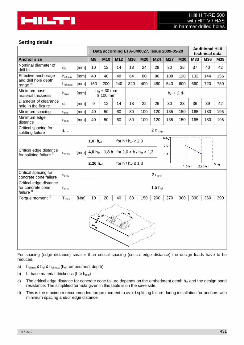
Setting details
Data according ETA-04/0027, issue 2009-05-20 Additional Hilti technical data
Anchor size M8 M10 M12 M16 M20 M24 M27 M30 M33 M36 M39 Nominal diameter of drill bit d0 [mm] 10 12 14 18 24 28 30 35 37 40 42
Effective anchorage and drill hole depth range a)
hef,min [mm] 40 40 48 64 80 96 108 120 132 144 156
hef,max [mm] 160 200 240 320 400 480 540 600 660 720 780
Minimum base material thickness
hmin [mm] hef + 30 mm ≥ 100 mm hef + 2 d0
Diameter of clearance hole in the fixture
df [mm] 9 12 14 18 22 26 30 33 36 39 42
Minimum spacing smin [mm] 40 50 60 80 100 120 135 150 165 180 195 Minimum edge distance cmin [mm] 40 50 60 80 100 120 135 150 165 180 195
Critical spacing for splitting failure scr,sp 2 ccr,sp
Critical edge distance for splitting failure b) ccr,sp [mm]
1,0 ⋅⋅⋅⋅ hef for h / hef ≥ 2,0
4,6 hef - 1,8 h for 2,0 > h / hef > 1,3
2,26 hef for h / hef ≤ 1,3
Critical spacing for concrete cone failure scr,N 2 ccr,N
Critical edge distance for concrete cone failure c)
ccr,N 1,5 hef
Torque moment d) Tmax [Nm] 10 20 40 80 150 200 270 300 330 360 390
For spacing (edge distance) smaller than critical spacing (critical edge distance) the design loads have to be reduced.
a) hef,min ≤ hef ≤ hef,max (hef: embedment depth)
b) h: base material thickness (h ≥ hmin)
c) The critical edge distance for concrete cone failure depends on the embedment depth hef and the design bond resistance. The simplified formula given in this table is on the save side.
d) This is the maximum recommended torque moment to avoid splitting failure during installation for anchors with minimum spacing and/or edge distance.

Hilti HIT-RE 500 with HIT-V / HAS in hammer drilled holes
09 / 2012
432
Simplified design method Simplified version of the design method according ETAG 001, TR 029. Design resistance according data given in ETA-04/0027, issue 2009-05-20.
� Influence of concrete strength � Influence of edge distance � Influence of spacing � Valid for a group of two anchors. (The method may also be applied for anchor groups with more than two
anchors or more than one edge distance. The influencing factors must then be considered for each edge distance and spacing. The calculated design loads are then on the save side: They will be lower than the exact values according ETAG 001, TR 029. To avoid this, it is recommended to use the anchor design software PROFIS anchor)
The design method is based on the following simplification: � No different loads are acting on individual anchors (no eccentricity)
The values are valid for one anchor. For more complex fastening applications please use the anchor design software PROFIS Anchor.
Tension loading
The design tensile resistance is the lower value of
- Steel resistance: NRd,s
- Combined pull-out and concrete cone resistance: NRd,p = N0
Rd,p ⋅⋅⋅⋅ fB,p ⋅⋅⋅⋅ f1,N ⋅⋅⋅⋅ f2,N ⋅⋅⋅⋅ f3,N ⋅⋅⋅⋅ fh,p ⋅⋅⋅⋅ fre,N
- Concrete cone resistance: NRd,c = N0Rd,c ⋅⋅⋅⋅ fB ⋅⋅⋅⋅ f1,N ⋅⋅⋅⋅ f2,N ⋅⋅⋅⋅ f3,N ⋅⋅⋅⋅ fh,N ⋅⋅⋅⋅ fre,N
- Concrete splitting resistance (only non-cracked concrete): NRd,sp = N0
Rd,c ⋅⋅⋅⋅ fB ⋅⋅⋅⋅ f1,sp ⋅⋅⋅⋅ f2,sp ⋅⋅⋅⋅ f3,sp ⋅⋅⋅⋅ fh,N ⋅⋅⋅⋅ fre,N
Basic design tensile resistance
Design steel resistance N Rd,s Data according ETA-04/0027, issue 2009-05-20 Additional Hilti
technical data Anchor size M8 M10 M12 M16 M20 M24 M27 M30 M33 M36 M39
NRd,s
HAS 5.8 [kN] 11,3 17,3 25,3 48,0 74,7 106,7 - - - - - HIT-V 5.8 [kN] 12,0 19,3 28,0 52,7 82,0 118,0 153,3 187,3 231,3 272,3 325,3 HAS 8.8 [kN] - - - - - - 231,3 281,3 345,1 404,8 486,9 HIT-V 8.8 [kN] 19,3 30,7 44,7 84,0 130,7 188,0 244,7 299,3 370,1 435,7 520,5 HAS (-E)-R [kN] 12,3 19,8 28,3 54,0 84,0 119,8 75,9 92,0 113,2 132,8 159,8 HIT-V-R [kN] 13,9 21,9 31,6 58,8 92,0 132,1 80,4 98,3 122,6 144,3 172,4 HAS (-E)-HCR [kN] 18,0 28,0 40,7 76,7 120,0 106,7 144,8 175,7 134,8 158,1 190,2 HIT-V-HCR [kN] 19,3 30,7 44,7 84,0 130,7 117,6 152,9 187,1 144,6 170,2 203,3

Hilti HIT-RE 500 with HIT-V / HAS
in hammer drilled holes
09 / 2012
433
Design combined pull -out and concrete cone resistance for anchors in diamond drilled holes a) NRd,p = N0
Rd,p ⋅⋅⋅⋅ fB,p ⋅⋅⋅⋅ f1,N ⋅⋅⋅⋅ f2,N ⋅⋅⋅⋅ f3,N ⋅⋅⋅⋅ fh,p ⋅⋅⋅⋅ fre,N Data according ETA-04/0027, issue 2009-05-20 Additional Hilti
technical data Anchor size M8 M10 M12 M16 M20 M24 M27 M30 M33 M36 M39 Typical embedment depth hef,typ [mm] 80 90 110 125 170 210 240 270 300 330 360
N0Rd,p Temperature range I [kN] 15,3 21,5 31,6 44,9 76,3 105,6 135,7 157,5 171,0 203,3 232,9
N0Rd,p Temperature range II [kN] 12,4 17,5 25,7 35,9 61,0 82,9 106,6 133,3 136,8 162,6 186,3
N0Rd,p Temperature range III [kN] 7,7 10,8 15,8 22,4 35,6 52,8 63,0 78,8 82,1 97,6 111,8
a) Additional Hilti technical data (not part of ETA-04 /0027, issue 2009-05-20): The design values for combined pull-out and concrete cone resistance may be increased by 20 % for anchor
installation in dry concrete (concrete not in contact with water before/during installation and curing). Design concrete cone resistance a) NRd,c = N0
Rd,c ⋅⋅⋅⋅ fB ⋅⋅⋅⋅ f1,N ⋅⋅⋅⋅ f2,N ⋅⋅⋅⋅ f3,N ⋅⋅⋅⋅ fh,N ⋅⋅⋅⋅ fre,N Design splitting resistance N Rd,sp a) = N0
Rd,c ⋅⋅⋅⋅ fB ⋅⋅⋅⋅ f1,sp ⋅⋅⋅⋅ f2,sp ⋅⋅⋅⋅ f3,sp ⋅⋅⋅⋅ f h,N ⋅⋅⋅⋅ fre,N Data according ETA-04/0027, issue 2009-05-20 Additional Hilti
technical data Anchor size M8 M10 M12 M16 M20 M24 M27 M30 M33 M36 M39 N0
Rd,c [kN] 17,2 20,5 27,7 33,6 53,3 73,2 89,4 106,7 125,0 144,2 164,3 a) Additional Hilti technical data (not part of ETA-04 /0027, issue 2009-05-20): The design values for concrete cone and splitting resistance may be increased by 20 % for anchor installation
in dry concrete (concrete not in contact with water before/during installation and curing). Influencing factors
Influence of concrete strength on combined pull -out and concrete cone resistance
Concrete strength designation (ENV 206)
C 20/25 C 25/30 C 30/37 C 35/45 C 40/50 C 45/55 C 50/60
fB,p = (fck,cube/25N/mm²)0,1 a) 1 1,02 1,04 1,06 1,07 1,08 1,09 a) fck,cube = concrete compressive strength, measured on cubes with 150 mm side length Influence of embedment depth on combined pull -out and concrete cone resistance
fh,p = hef/hef,typ
Influence of concrete strength on concrete cone res istance
Concrete strength designation (ENV 206)
C 20/25 C 25/30 C 30/37 C 35/45 C 40/50 C 45/55 C 50/60
fB = (fck,cube/25N/mm²)1/2 a) 1 1,1 1,22 1,34 1,41 1,48 1,55 a) fck,cube = concrete compressive strength, measured on cubes with 150 mm side length

Hilti HIT-RE 500 with HIT-V / HAS in hammer drilled holes
09 / 2012
434
Influence of edge distance a)
c/c cr,N 0,1 0,2 0,3 0,4 0,5 0,6 0,7 0,8 0,9 1
c/c cr,sp
f1,N = 0,7 + 0,3⋅c/ccr,N 0,73 0,76 0,79 0,82 0,85 0,88 0,91 0,94 0,97 1
f1,sp = 0,7 + 0,3⋅c/ccr,sp
f2,N = 0,5⋅(1 + c/ccr,N) 0,55 0,60 0,65 0,70 0,75 0,80 0,85 0,90 0,95 1
f2,sp = 0,5⋅(1 + c/ccr,sp) a) The the edge distance shall not be smaller than the minimum edge distance cmin given in the table with the
setting details. These influencing factors must be considered for every edge distance smaller than the critical edge distance.
Influence of anchor spacing a)
s/s cr,N 0,1 0,2 0,3 0,4 0,5 0,6 0,7 0,8 0,9 1
s/s cr,sp
f3,N = 0,5⋅(1 + s/scr,N) 0,55 0,60 0,65 0,70 0,75 0,80 0,85 0,90 0,95 1
f3,sp = 0,5⋅(1 + s/scr,sp) a) The anchor spacing shall not be smaller than the minimum anchor spacing smin given in the table with the
setting details. This influencing factor must be considered for every anchor spacing. Influence of embedment depth on concrete cone resis tance
fh,N = (hef/hef,typ )1,5
Influence of reinfor cement
hef [mm] 40 50 60 70 80 90 ≥ 100
fre,N = 0,5 + hef/200mm ≤ 1 0,7 a) 0,75 a) 0,8 a) 0,85 a) 0,9 a) 0,95 a) 1 a) This factor applies only for dense reinforcement. If in the area of anchorage there is reinforcement with a
spacing ≥ 150 mm (any diameter) or with a diameter ≤ 10 mm and a spacing ≥ 100 mm, then a factor fre = 1 may be applied.
Shear loading
The design shear resistance is the lower value of
- Steel resistance: VRd,s
- Concrete pryout resistance: VRd,cp = k ⋅⋅⋅⋅ lower value of NRd,p and NRd,c
- Concrete edge resistance: VRd,c = V0Rd,c ⋅⋅⋅⋅ fB ⋅⋅⋅⋅ fß ⋅⋅⋅⋅ f h ⋅⋅⋅⋅ f4 ⋅⋅⋅⋅ f hef ⋅⋅⋅⋅ fc

Hilti HIT-RE 500 with HIT-V / HAS
in hammer drilled holes
09 / 2012
435
Basic design shear resistance Design steel resistance V Rd,s Data according ETA-04/0027, issue 2009-05-20 Additional Hilti
technical data Anchor size M8 M10 M12 M16 M20 M24 M27 M30 M33 M36 M39
VRd,s
HAS 5.8 [kN] 6,8 10,4 15,2 28,8 44,8 64,0 - - - - - HIT-V 5.8 [kN] 7,2 12,0 16,8 31,2 48,8 70,4 92,0 112,0 138,8 163,4 195,2 HAS 8.8 [kN] - - - - - - 139,2 168,8 207,0 242,9 292,2 HIT-V 8.8 [kN] 12,0 18,4 27,2 50,4 78,4 112,8 147,2 179,2 222,1 261,4 312,3 HAS (-E)-R [kN] 7,7 12,2 17,3 32,7 50,6 71,8 45,8 55,5 67,9 79,7 95,9 HIT-V-R [kN] 8,3 12,8 19,2 35,3 55,1 79,5 48,3 58,8 72,9 85,8 102,5 HAS (-E)-HCR [kN] 10,4 16,8 24,8 46,4 72,0 64,0 86,9 105,7 80,9 94,9 114,1 HIT-V-HCR [kN] 12,0 18,4 27,2 50,4 78,4 70,9 92,0 112,0 86,8 102,1 122,0
Design concrete pryout resistance V Rd,cp = lower value a) of k ⋅⋅⋅⋅ NRd,p and k ⋅⋅⋅⋅ NRd,c
k = 1 for h ef < 60 mm k = 2 for h ef ≥ 60 mm
a) NRd,p: Design combined pull-out and concrete cone resistance NRd,c: Design concrete cone resistance
Design concrete edge resistance V Rd,c = V0
Rd,c ⋅⋅⋅⋅ fB ⋅⋅⋅⋅ fß ⋅⋅⋅⋅ f h ⋅⋅⋅⋅ f4 ⋅⋅⋅⋅ f hef ⋅⋅⋅⋅ fc Anchor size M8 M10 M12 M16 M20 M24 M27 M30 M33 M36 M39 Non-cracked concrete V0
Rd,c [kN] 5,9 8,6 11,6 18,7 27,0 36,6 44,5 53,0 62,1 71,7 81,9 Influencing factors
Influence of concrete strength
Concrete strength designation (ENV 206) C 20/25 C 25/30 C 30/37 C 35/45 C 40/50 C 45/55 C 50/60
fB = (fck,cube/25N/mm²)1/2 a) 1 1,1 1,22 1,34 1,41 1,48 1,55 a) fck,cube = concrete compressive strength, measured on cubes with 150 mm side length Influence of angle between load applied and the dir ection perpendicular to the free edge
Angle ß 0° 10° 20° 30° 40° 50° 60° 70° 80° ≥ 90°
( )2
2
5,2
sincos
1
+
=V
V
fα
αβ
1 1,01 1,05 1,13 1,24 1,40 1,64 1,97 2,32 2,50
Influence of base material thickness
h/c 0,15 0,3 0,45 0,6 0,75 0,9 1,05 1,2 1,35 ≥ 1,5
f h = {h/(1,5 ⋅ c)} 1/2 ≤ 1 0,32 0,45 0,55 0,63 0,71 0,77 0,84 0,89 0,95 1,00

Hilti HIT-RE 500 with HIT-V / HAS in hammer drilled holes
09 / 2012
436
Influence of anchor spacing and edge distance a) for concrete edge resistance: f 4 f4 = (c/hef)1,5 ⋅⋅⋅⋅ (1 + s / [3 ⋅⋅⋅⋅ c]) ⋅⋅⋅⋅ 0,5
c/h ef Single anchor
Group of two anchors s/h ef 0,75 1,50 2,25 3,00 3,75 4,50 5,25 6,00 6,75 7,50 8,25 9,00 9,75 10,50 11,25
0,50 0,35 0,27 0,35 0,35 0,35 0,35 0,35 0,35 0,35 0,35 0,35 0,35 0,35 0,35 0,35 0,35 0,75 0,65 0,43 0,54 0,65 0,65 0,65 0,65 0,65 0,65 0,65 0,65 0,65 0,65 0,65 0,65 0,65 1,00 1,00 0,63 0,75 0,88 1,00 1,00 1,00 1,00 1,00 1,00 1,00 1,00 1,00 1,00 1,00 1,00 1,25 1,40 0,84 0,98 1,12 1,26 1,40 1,40 1,40 1,40 1,40 1,40 1,40 1,40 1,40 1,40 1,40 1,50 1,84 1,07 1,22 1,38 1,53 1,68 1,84 1,84 1,84 1,84 1,84 1,84 1,84 1,84 1,84 1,84 1,75 2,32 1,32 1,49 1,65 1,82 1,98 2,15 2,32 2,32 2,32 2,32 2,32 2,32 2,32 2,32 2,32 2,00 2,83 1,59 1,77 1,94 2,12 2,30 2,47 2,65 2,83 2,83 2,83 2,83 2,83 2,83 2,83 2,83 2,25 3,38 1,88 2,06 2,25 2,44 2,63 2,81 3,00 3,19 3,38 3,38 3,38 3,38 3,38 3,38 3,38 2,50 3,95 2,17 2,37 2,57 2,77 2,96 3,16 3,36 3,56 3,76 3,95 3,95 3,95 3,95 3,95 3,95 2,75 4,56 2,49 2,69 2,90 3,11 3,32 3,52 3,73 3,94 4,15 4,35 4,56 4,56 4,56 4,56 4,56 3,00 5,20 2,81 3,03 3,25 3,46 3,68 3,90 4,11 4,33 4,55 4,76 4,98 5,20 5,20 5,20 5,20 3,25 5,86 3,15 3,38 3,61 3,83 4,06 4,28 4,51 4,73 4,96 5,18 5,41 5,63 5,86 5,86 5,86 3,50 6,55 3,51 3,74 3,98 4,21 4,44 4,68 4,91 5,14 5,38 5,61 5,85 6,08 6,31 6,55 6,55 3,75 7,26 3,87 4,12 4,36 4,60 4,84 5,08 5,33 5,57 5,81 6,05 6,29 6,54 6,78 7,02 7,26 4,00 8,00 4,25 4,50 4,75 5,00 5,25 5,50 5,75 6,00 6,25 6,50 6,75 7,00 7,25 7,50 7,75 4,25 8,76 4,64 4,90 5,15 5,41 5,67 5,93 6,18 6,44 6,70 6,96 7,22 7,47 7,73 7,99 8,25 4,50 9,55 5,04 5,30 5,57 5,83 6,10 6,36 6,63 6,89 7,16 7,42 7,69 7,95 8,22 8,49 8,75 4,75 10,35 5,45 5,72 5,99 6,27 6,54 6,81 7,08 7,36 7,63 7,90 8,17 8,45 8,72 8,99 9,26 5,00 11,18 5,87 6,15 6,43 6,71 6,99 7,27 7,55 7,83 8,11 8,39 8,66 8,94 9,22 9,50 9,78 5,25 12,03 6,30 6,59 6,87 7,16 7,45 7,73 8,02 8,31 8,59 8,88 9,17 9,45 9,74 10,02 10,31
5,50 12,90 6,74 7,04 7,33 7,62 7,92 8,21 8,50 8,79 9,09 9,38 9,67 9,97 10,26 10,55 10,85
a) The anchor spacing and the edge distance shall not be smaller than the minimum anchor spacing smin and the minimum edge distance cmin. Influence of embedment depth
hef/d 4 4,5 5 6 7 8 9 10 11
f hef = 0,05 ⋅ (hef / d)1,68 0,51 0,63 0,75 1,01 1,31 1,64 2,00 2,39 2,81 hef/d 12 13 14 15 16 17 18 19 20
f hef = 0,05 ⋅ (hef / d)1,68 3,25 3,72 4,21 4,73 5,27 5,84 6,42 7,04 7,67 Influence of edge distance a)
c/d 4 6 8 10 15 20 30 40
fc = (d / c)0,19 0,77 0,71 0,67 0,65 0,60 0,57 0,52 0,50 a) The edge distance shall not be smaller than the minimum edge distance cmin.
Combined tension and shear loading For combined tension and shear loading see section “Anchor Design”. Precalculated values Recommended loads can be calculated by dividing the design resistance by an overall partial safety factor for action γ = 1,4. The partial safety factors for action depend on the type of loading and shall be taken from national regulations.

Hilti HIT-RE 500 with HIT-V / HAS
in hammer drilled holes
09 / 2012
437
Design resistance: concrete C 20/25 – fck,cube = 25 N/mm², Temperature range I Data according ETA-04/0027, issue 2009-05-20 Additional Hilti
technical data Anchor size M8 M10 M12 M16 M20 M24 M27 M30 M33 M36 M39 Embedment depth hef,1 = [mm] 48 60 72 96 120 144 162 180 198 216 234 Base material thickness hmin= [mm] 100 100 102 132 168 200 222 250 272 296 324
Tensile N Rd: single anchor, no edge effects
HIT-V 5.8 HIT-V 8.8 HIT-V-R HIT-V-HCR
[kN] 8,0 11,2 14,7 22,6 31,6 41,6 49,6 58,1 67,0 76,3 86,1
Shear VRd: single anchor, no edge e ffects, without lever arm HIT-V 5.8 [kN] 7,2 12,0 16,8 31,2 48,8 70,4 92,0 112,0 138,8 163,4 195,2 HIT-V 8.8 [kN] 11,2 18,4 27,2 50,4 78,4 112,8 138,8 162,6 187,6 213,8 241,0 HIT-V-R [kN] 8,3 12,8 19,2 35,3 55,1 79,5 48,3 58,8 72,9 85,8 102,5 HIT-V-HCR [kN] 11,2 18,4 27,2 50,4 78,4 70,9 92,0 112,0 86,8 102,1 122,0
Design resistance: concrete C 20/25 – fck,cube = 25 N/mm², Temperature range I Data according ETA-04/0027, issue 2009-05-20 Additional Hilti
technical data Anchor size M8 M10 M12 M16 M20 M24 M27 M30 M33 M36 M39 Embedment depth hef,1 = [mm] 48 60 72 96 120 144 162 180 198 216 234 Base material thickness hmin= [mm] 100 100 102 132 168 200 222 250 272 296 324 Edge distance c = cmin= [mm] 40 50 60 80 100 120 135 150 165 180 195
Tensile N Rd: single anchor, min. edge distance (c = c min ) HIT-V 5.8 HIT-V 8.8 HIT-V-R HIT-V-HCR
[kN] 5,4 7,3 8,5 12,9 18,2 23,8 28,2 33,2 38,1 43,4 49,2
Shear VRd: single anchor, min. edge distance (c = c min ) , without lever arm HIT-V 5.8 HIT-V 8.8 HIT-V-R HIT-V-HCR
[kN] 3,4 4,9 6,7 10,8 15,7 21,4 26,0 31,1 36,5 42,2 48,3
Design resistance: concrete C 20/25 – fck,cube = 25 N/mm², Temperature range I (load values are valid for single anchor) Data according ETA-04/0027, issue 2009-05-20 Additional Hilti
technical data Anchor size M8 M10 M12 M16 M20 M24 M27 M30 M33 M36 M39 Embedment depth hef,1 = [mm] 48 60 72 96 120 144 162 180 198 216 234 Base material thickness hmin= [mm] 100 100 102 132 168 200 222 250 272 296 324 Spacing s = smin= [mm] 40 50 60 80 100 120 135 150 165 180 195
Tensile N Rd: double anchor, no edge effects, min. spacing (s = smin ) HIT-V 5.8 HIT-V 8.8 HIT-V-R HIT-V-HCR
[kN] 5,1 7,0 8,8 13,5 19,0 24,9 29,6 34,8 40,1 45,6 51,5
Shear VRd: double anchor, no edge effects, min. spacing (s = s min ) , without lever arm HIT-V 5.8 [kN] 7,2 12,0 16,8 31,2 48,8 70,4 88,7 103,9 119,9 136,6 154,0 HIT-V 8.8 [kN] 7,2 18,4 26,3 40,5 56,5 74,3 88,7 103,9 119,9 136,6 154,0 HIT-V-R [kN] 7,2 12,8 19,2 35,3 55,1 74,3 48,3 58,8 72,9 85,8 102,5 HIT-V-HCR [kN] 7,2 18,4 26,3 40,5 56,5 70,9 88,7 103,9 86,8 102,1 122,0

Hilti HIT-RE 500 with HIT-V / HAS in hammer drilled holes
09 / 2012
438
Design resistance: concrete C 20/25 – fck,cube = 25 N/mm², Temperature range I Data according ETA-04/0027, issue 2009-05-20 Additional Hilti
technical data Anchor size M8 M10 M12 M16 M20 M24 M27 M30 M33 M36 M39 Embedment depth hef,typ = [mm] 80 90 110 125 170 210 240 270 300 330 360 Base material thickness hmin= [mm] 110 120 140 161 218 266 300 340 374 410 450
Tensile N Rd: single anchor, no edge effects
HIT-V 5.8 [kN] 12,0 19,3 27,7 33,6 53,3 73,2 89,4 106,7 125,0 144,2 164,3 HIT-V 8.8 [kN] 15,3 20,5 27,7 33,6 53,3 73,2 89,4 106,7 125,0 144,2 164,3 HIT-V-R [kN] 13,9 20,5 27,7 33,6 53,3 73,2 80,4 98,3 122,6 144,2 164,3 HIT-V-HCR [kN] 15,3 20,5 27,7 33,6 53,3 73,2 89,4 106,7 125,0 144,2 164,3
Shear VRd: single anchor, no edge effects, without lever arm HIT-V 5.8 [kN] 7,2 12,0 16,8 31,2 48,8 70,4 92,0 112,0 138,8 163,4 195,2 HIT-V 8.8 [kN] 12,0 18,4 27,2 50,4 78,4 112,8 147,2 179,2 222,1 261,4 312,3 HIT-V-R [kN] 8,3 12,8 19,2 35,3 55,1 79,5 48,3 58,8 72,9 85,8 102,5 HIT-V-HCR [kN] 12,0 18,4 27,2 50,4 78,4 70,9 92,0 112,0 86,8 102,1 122,0
Design resistance: concrete C 20/25 – fck,cube = 25 N/mm², Temperature range I Data according ETA-04/0027, issue 2009-05-20 Additional Hilti
technical data Anchor size M8 M10 M12 M16 M20 M24 M27 M30 M33 M36 M39 Embedment depth hef,typ = [mm] 80 90 110 125 170 210 240 270 300 330 360 Base material thickness hmin= [mm] 110 120 140 161 218 266 300 340 374 410 450 Edge distance c = cmin= [mm] 40 50 60 80 100 120 135 150 165 180 195
Tensile N Rd: single anchor, min. edge distance (c = c min ) HIT-V 5.8 HIT-V 8.8 HIT-V-R HIT-V-HCR
[kN] 8,2 10,0 13,3 16,9 26,1 35,6 43,3 51,4 60,0 69,1 78,6
Shear VRd: single anchor, min. edge distance (c = c min ) , without lever arm HIT-V 5.8 HIT-V 8.8 HIT-V-R HIT-V-HCR
[kN] 3,7 5,3 7,3 11,5 17,2 23,6 29,0 34,8 41,1 47,8 54,9
Design resistance: concrete C 20/25 – fck,cube = 25 N/mm², Temperature range I (load values are valid for single anchor) Data according ETA-04/0027, issue 2009-05-20 Additional Hilti
technical data Anchor size M8 M10 M12 M16 M20 M24 M27 M30 M33 M36 M39 Embedment depth hef,typ = [mm] 80 90 110 125 170 210 240 270 300 330 360 Base material thickness hmin= [mm] 110 120 140 161 218 266 300 340 374 410 450 Spacing s = smin= [mm] 40 50 60 80 100 120 135 150 165 180 195
Tensile N Rd: double anchor, no edge effects, min. spacing (s = smin ) HIT-V 5.8 HIT-V 8.8 HIT-V-R HIT-V-HCR
[kN] 9,3 11,6 15,5 19,2 30,1 41,2 50,3 59,9 70,1 80,8 92,0
Shear VRd: double anchor, no edge effects, min. spacing (s = smin ) , without lever arm HIT-V 5.8 [kN] 7,2 12,0 16,8 31,2 48,8 70,4 92,0 112,0 138,8 163,4 195,2 HIT-V 8.8 [kN] 12,0 18,4 27,2 50,4 78,4 112,8 147,2 177,0 207,0 238,5 271,5 HIT-V-R [kN] 8,3 12,8 19,2 35,3 55,1 79,5 48,3 58,8 72,9 85,8 102,5 HIT-V-HCR [kN] 12,0 18,4 27,2 50,4 78,4 70,9 92,0 112,0 86,8 102,1 122,0
Hilti HIT-RE 500 with HIT-V / HAS
in hammer drilled holes
09 / 2012
439
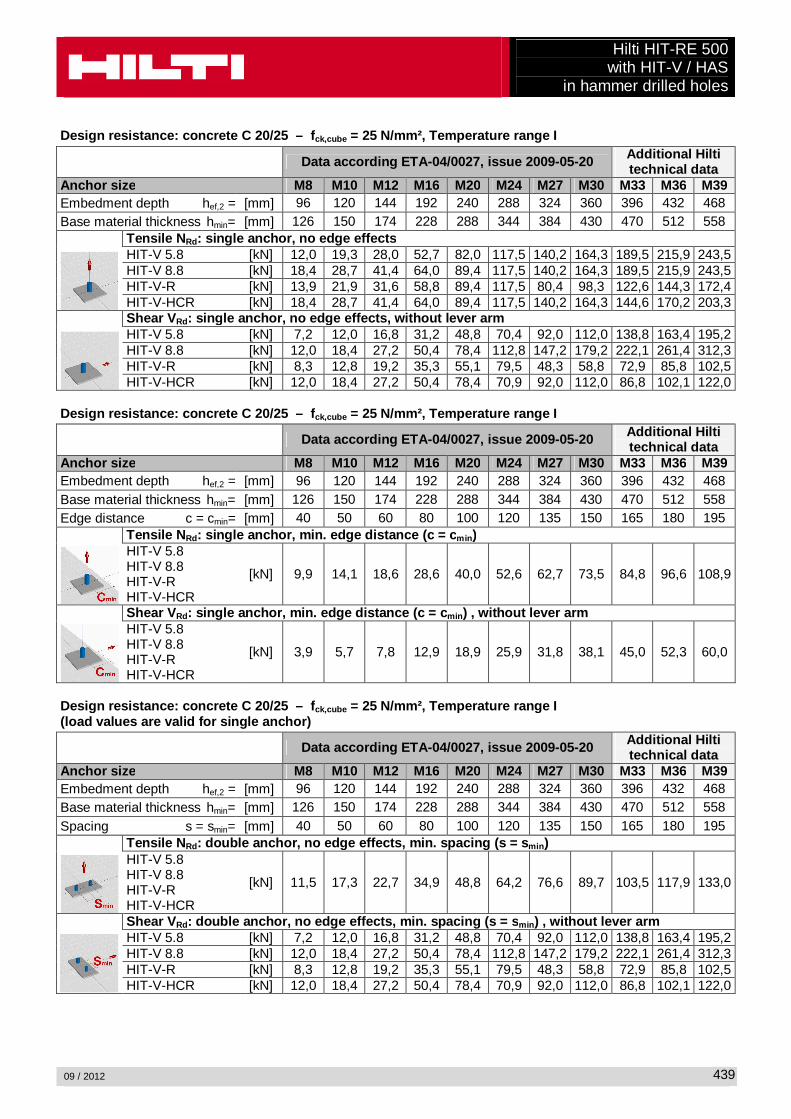
Design resistance: concrete C 20/25 – fck,cube = 25 N/mm², Temperature range I Data according ETA-04/0027, issue 2009-05-20 Additional Hilti
technical data Anchor size M8 M10 M12 M16 M20 M24 M27 M30 M33 M36 M39 Embedment depth hef,2 = [mm] 96 120 144 192 240 288 324 360 396 432 468 Base material thickness hmin= [mm] 126 150 174 228 288 344 384 430 470 512 558
Tensile N Rd: single anchor, no edge effects
HIT-V 5.8 [kN] 12,0 19,3 28,0 52,7 82,0 117,5 140,2 164,3 189,5 215,9 243,5 HIT-V 8.8 [kN] 18,4 28,7 41,4 64,0 89,4 117,5 140,2 164,3 189,5 215,9 243,5 HIT-V-R [kN] 13,9 21,9 31,6 58,8 89,4 117,5 80,4 98,3 122,6 144,3 172,4 HIT-V-HCR [kN] 18,4 28,7 41,4 64,0 89,4 117,5 140,2 164,3 144,6 170,2 203,3
Shear VRd: single anchor, no edge effects, without lever arm HIT-V 5.8 [kN] 7,2 12,0 16,8 31,2 48,8 70,4 92,0 112,0 138,8 163,4 195,2 HIT-V 8.8 [kN] 12,0 18,4 27,2 50,4 78,4 112,8 147,2 179,2 222,1 261,4 312,3 HIT-V-R [kN] 8,3 12,8 19,2 35,3 55,1 79,5 48,3 58,8 72,9 85,8 102,5 HIT-V-HCR [kN] 12,0 18,4 27,2 50,4 78,4 70,9 92,0 112,0 86,8 102,1 122,0
Design resistance: concret e C 20/25 – fck,cube = 25 N/mm², Temperature range I Data according ETA-04/0027, issue 2009-05-20 Additional Hilti
technical data Anchor size M8 M10 M12 M16 M20 M24 M27 M30 M33 M36 M39 Embedment depth hef,2 = [mm] 96 120 144 192 240 288 324 360 396 432 468 Base material thickness hmin= [mm] 126 150 174 228 288 344 384 430 470 512 558 Edge distance c = cmin= [mm] 40 50 60 80 100 120 135 150 165 180 195
Tensile N Rd: single anchor, min. edge distance (c = c min ) HIT-V 5.8 HIT-V 8.8 HIT-V-R HIT-V-HCR
[kN] 9,9 14,1 18,6 28,6 40,0 52,6 62,7 73,5 84,8 96,6 108,9
Shear VRd: single anchor, min. edge distance (c = c min ) , without lever arm HIT-V 5.8 HIT-V 8.8 HIT-V-R HIT-V-HCR
[kN] 3,9 5,7 7,8 12,9 18,9 25,9 31,8 38,1 45,0 52,3 60,0
Design resistan ce: concrete C 20/25 – fck,cube = 25 N/mm², Temperature range I (load values are valid for single anchor) Data according ETA-04/0027, issue 2009-05-20 Additional Hilti
technical data Anchor size M8 M10 M12 M16 M20 M24 M27 M30 M33 M36 M39 Embedment depth hef,2 = [mm] 96 120 144 192 240 288 324 360 396 432 468 Base material thickness hmin= [mm] 126 150 174 228 288 344 384 430 470 512 558 Spacing s = smin= [mm] 40 50 60 80 100 120 135 150 165 180 195
Tensile N Rd: double anchor, no edge effects, min . spacing (s = s min ) HIT-V 5.8 HIT-V 8.8 HIT-V-R HIT-V-HCR
[kN] 11,5 17,3 22,7 34,9 48,8 64,2 76,6 89,7 103,5 117,9 133,0
Shear VRd: double anchor, no edge effects, min. spacing (s = smin ) , without lever arm HIT-V 5.8 [kN] 7,2 12,0 16,8 31,2 48,8 70,4 92,0 112,0 138,8 163,4 195,2 HIT-V 8.8 [kN] 12,0 18,4 27,2 50,4 78,4 112,8 147,2 179,2 222,1 261,4 312,3 HIT-V-R [kN] 8,3 12,8 19,2 35,3 55,1 79,5 48,3 58,8 72,9 85,8 102,5 HIT-V-HCR [kN] 12,0 18,4 27,2 50,4 78,4 70,9 92,0 112,0 86,8 102,1 122,0