Embed Size (px)
Citation preview

7/23/2019 Hiltesting Bms
http://slidepdf.com/reader/full/hiltesting-bms 1/12
Development of Real-Time BatteryModels for HIL testing of Battery
Management Systems (BMS)
7/23/2019 Hiltesting Bms
http://slidepdf.com/reader/full/hiltesting-bms 2/12
The explosion in the use of elec-
tronic devices, electrified vehicles
and decentralized power utilities
(e.g. smart grids) has driven demand
for rechargeable batteries, creating a
thriving and growing market. Current
projections indicate that the g lobal
market for rechargeable batteries will
be approximately $60 billion in 2015,
growing at around 9% per year. This
has led many of the major electronics
companies to enter the market, with
offerings targeting a range of applica-
tions: from small and light-weight for
hand-held devices to batteries the size
of shipping containers for utilities. It
has also led to a significant increase
in research investment into battery
technologies to address many of thetechnical challenges facing this indus-
try, ranging from increasing specific
energy (the amount of charge a cell
can hold per kg weight) to thermal
stability, battery life extension, and
final disposal of spent materials at the
end of a battery’s life (Battery, 2015).
In this paper, we will focus on one area
of development in the context of a
project recently carried out by Maplesoft
and its partner, ControlWorks Inc,
of South Korea. Specifically, we will
cover the development of a
Hardware-in-the-Loop (HIL)
testing system for the Battery
Management Systems (BMS) used
in one of our client’s larger electrical
energy storage products, targeting
the Smart Grid and UPS markets.
Maplesoft’s role in this project was to
develop a high-fidelity battery packmodel capable of being executed on
a real-time platform. This has since
been integrated into a turn-key BMS
testing system, developed by
ControlWorks.
The paper is structured in fourparts:
• A description of the client’s
requirements for the project
• A discussion of the current state-of-
the-art tools for modeling battery
cells and how this is implementedin the MapleSim™ Battery Library
• A detailed description of the
modeling approach used for this
particular project
• How the battery stack model was
integrated into the BMS testing
system from ControlWorks.
Project Requirements
The client involved in this project is a
major consumer electronics producer
that also offers a wide range of
solutions for industrial applications
including electrical Energy Storage
Systems (ESS). Essentially, these are
stacks of a large number of battery
cells that are typically used for off-
grid power supplies in residential
and commercial applications, such
as uninterruptable power supplies,
renewable-energy systems and remote
telecom systems.
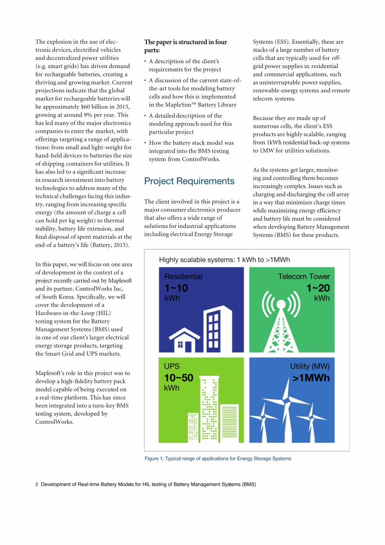
Because they are made up of
numerous cells, the client’s ESS
products are highly scalable, ranging
from 1kWh residential back-up systems
to 1MW for utilities solutions.
As the systems get larger, monitor-
ing and controlling them becomes
increasingly complex. Issues such as
charging and discharging the cell array
in a way that minimizes charge times
while maximizing energy efficiency
and battery life must be considered
when developing Battery Management
Systems (BMS) for these products.
2 Development of Real-time Battery Models for HIL testing of Battery Management Systems (BMS)
Highly scalable systems: 1 kWh to >1MWh
Residenti al1 ~10 kWh
UPS
10~50 kWh
Residential
1~10 kWh
Telecom Tower
1~20kWh
Utility (MW)
>1MWh
Figure 1: Typical range of applications for Energy Storage Systems

7/23/2019 Hiltesting Bms
http://slidepdf.com/reader/full/hiltesting-bms 3/123 Development of Real-time Battery Models for HIL testing of Battery Management Systems (BMS)
In particular, testing the BMS poses
major challenges: they are costly to
put together, faults in the BMS design
can cause catastrophic damage to verycostly test units, and often it may not
be possible to test for all scenarios,
like charge balancing across the
cells., All this can lead to excessive
uncertainty around the test results.
An attractive solution to these early-
stage BMS testing challenges is to
use virtual batteries – mathematical
models of the battery cells that are
capable of displaying the same dynamic
behavior as the real ones. Maplesoft
has been actively developing such
mathematical models for several
years. Not only are they proven to be
highly accurate, they are computa-
tionally efficient and able to achieve
the execution performance required
to deliver real-time performance for
batteries containing hundreds of cells
on real-time platforms.
It is for this reason that our client
selected Maplesoft Engineering
Solutions to develop the virtual
battery for implementation on a
turn-key BMS test system, developed
by Maplesoft’s partner, ControlWorks,
Inc. of South Korea.
Maplesoft’s role in the project was to
deliver a battery model capable of
being configured to represent a stack
of up to 144 cells that can be con-
nected in any combination of parallel
and series networks. Fault modes
were also required, such as individual
cells shorting or opening, along with
variations in charge capacity from cell
to cell, and degradation of capacity
over the life of the cells.
Approaches to
developing high-delity
battery models
Before delving into the project in
detail, let’s take a look at the current
state-of-the-art for modeling battery
cells and how these approaches are
implemented in the MapleSim
Battery Library.
There are two main approaches to
battery modeling. The first is to use
equivalent electrical circuits that
reflect charge capacity and internal
resistance through the use of standard
electrical components to represent
these properties. These equivalent-
circuit models are conceptually
simple and computationally light,
while capable of capturing many of
the non-linear behaviors within
the cell. However, their scope of
operation is somewhat limited and it
is not easy to map the components of
the model to the physical aspects of the
real cell.
At the opposite extreme, electrochem-
istry-based battery models – those
that include the details of the
underlying physics in the reactionbetween the electrodes and electro-
lytes – have been shown to be highly
accurate predictors of the overall
charge/discharge characteristics of a
cell. This physical behavior can
be represented by a system of well-
documented partial differential
equations (PDE), such as those devel-
oped by Newman. However, solving
these PDEs can only be achieved
through the use of computationally
intensive techniques such as finite-
element (FE) and computational fluid
dynamics (CFD) methods. These
approaches make them unsuitable for
system-level modeling since they can
Figure 2: Typical BMS testing systems with
real batteries are expensive and potentially
dangerous. Replacing the real battery with a
virtual battery reduces costs and risk
Figure 3: Typical simulated charge/discharge results from the MapleSim
Battery Library for various cell chemistries
§ Discharge voltage with pulse current (30 A) § Battery voltage with different cathodechemistries
TM
7/23/2019 Hiltesting Bms
http://slidepdf.com/reader/full/hiltesting-bms 4/12
take hours to compute the behaviorover a few seconds. Certainly, this
makes it impossible for the real-time
applications required for this project.
However, in the last few years a new
technique has been developed. This
compromise approach provides
real-time performance while almost
completely maintaining the accuracy
of the full physics models. This uses a
rigorous PDE discretization technique
to simplify the model to a set of
ordinary differential equations (ODE)
that can be readily solved by system-
level tools like MapleSim. Further-
more, through the many advanced
model optimization techniques
employed in MapleSim, the resulting
model code is very fast and capable of
running in real-time (Dao, 2011).
Using these physics-based models, it
is possible to implement batterymodels that predict charge/discharge
rates, state of charge (SoC), heat
generation and state of health (SoH)
through a wide range of loading
cycles within complex, multi-domain
system models. This approach
provides the performance needed for
system-level studies, with minimal
loss in model fidelity.
Furthermore, the underlyingfoundation for model formulation
and integration in MapleSim is based
on the conservation of energy.
Therefore, where there are inherent
inefficiencies in the model, lost
energy is computed as well as the
effective (or “useful”) energy. This
means that the user can consider a
certain proportion of the energy lost
through heat (very close to 100% in
applications like this). This makes
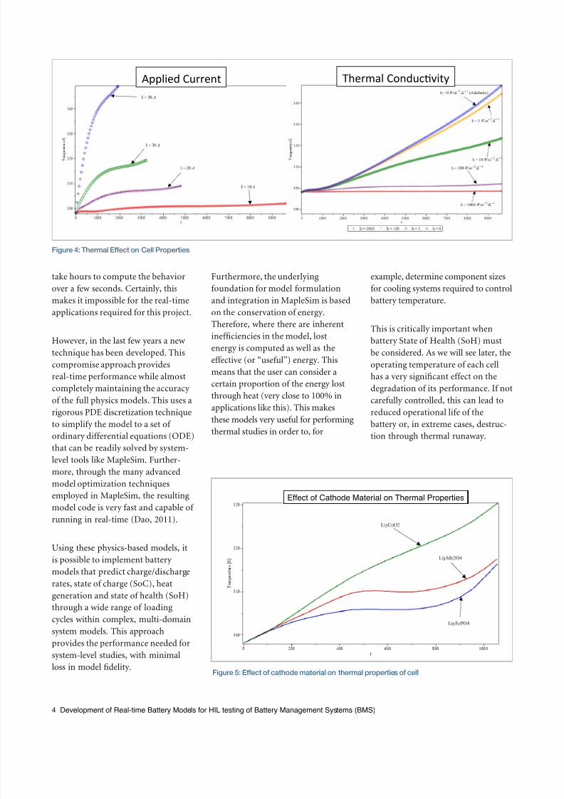
these models very useful for performingthermal studies in order to, for
example, determine component sizesfor cooling systems required to control
battery temperature.
This is critically important when
battery State of Health (SoH) must
be considered. As we will see later, the
operating temperature of each cell
has a very significant effect on the
degradation of its performance. If not
carefully controlled, this can lead to
reduced operational life of the
battery or, in extreme cases, destruc-
tion through thermal runaway.
4 Development of Real-time Battery Models for HIL testing of Battery Management Systems (BMS)
Applied Current Thermal Conduc3vity
Figure 4: Thermal Eect on Cell Properties
Effect of Cathode Material on Thermal Properties
Figure 5: Eect of cathode material on thermal properties of cell

7/23/2019 Hiltesting Bms
http://slidepdf.com/reader/full/hiltesting-bms 5/12
Thermal runaway is a common prob-
lem in many battery-powered systems.
It arises due to unforeseen loading
cycles driving the current to a point
where the cooling system cannot
dissipate the lost energy quickly
enough, or the cooling system is some-
how compromised so the battery heats
up. As the battery heats, its efficiency
decreases, causing even more energy
loss. Left unchecked, this vicious cycle
can cause the battery temperature to
increase to dangerous levels, leading
to failure or, in extreme cases, fire or
explosion.
Using MapleSim with the MapleSim
Battery Library, it is possible to repli-
cate these scenarios to understand theunderlying causes and develop strate-
gies for addressing or avoiding them.
Modeling State of
Health (SoH)
Within the MapleSim Battery Library,
SoH or capacity fading – during both
storage and cycling - is incorporated
in both the electrochemical andequivalent circuit models. Studies
have shown that the primary cause of
capacity fade in the cell is the growth
of the Solid Electrolyte Interface (SEI)
film between the electrodes and elec-
trolyte. This is caused by the chemical
reaction between the two, very similar
to corrosion. When the battery is new,
the reaction is quite vigorous and an
initial SEI forms, slowing down the
reaction and protecting the electrode
surfaces during battery operation.
However, as the battery ages, the SEI
slowly thickens in a predictable manner,
gradually reducing battery capacity
and increasing internal resistance
throughout its operational life.
5 Development of Real-time Battery Models for HIL testing of Battery Management Systems (BMS)
§ Thermal run-away model for Li-ion pack:
Figure 6: Simulation of thermal runaway using the Li-Ion model from the
MapleSim Battery Library
Figure 7: Life model (SEI formation on the anode during charge), and implementation in
MapleSim
Figure 8: Results from Li-Ion simulation, showing eect of SEI on cell degradation
7/23/2019 Hiltesting Bms
http://slidepdf.com/reader/full/hiltesting-bms 6/12
The formation of the SEI is
dependent on several factors, such
as the number and depth of charge/
discharge cycles, as well as applied
current, time in storage, and
temperature. These can vary consid-
erably depending on the electrode/
electrolyte chemistries used.
In order to factor SoH into the
battery models, these properties are
implemented in the battery library
as parameters and look-up tables,
depending on the chemistries
selected.
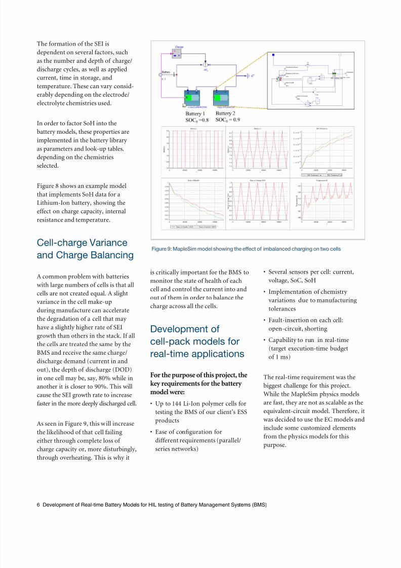
Figure 8 shows an example model
that implements SoH data for a
Lithium-Ion battery, showing the
effect on charge capacity, internal
resistance and temperature.
Cell-charge Variance
and Charge Balancing
A common problem with batteries
with large numbers of cells is that all
cells are not created equal. A slight
variance in the cell make-up
during manufacture can accelerate
the degradation of a cell that may
have a slightly higher rate of SEI
growth than others in the stack. If all
the cells are treated the same by the
BMS and receive the same charge/
discharge demand (current in and
out), the depth of discharge (DOD)
in one cell may be, say, 80% while in
another it is closer to 90%. This will
cause the SEI growth rate to increasefaster in the more deeply discharged cell.
As seen in Figure 9, this will increase
the likelihood of that cell failing
either through complete loss of
charge capacity or, more disturbingly,
through overheating. This is why it
is critically important for the BMS to
monitor the state of health of each
cell and control the current into and
out of them in order to balance thecharge across all the cells.
Development of
cell-pack models for
real-time applications
For the purpose of this project, thekey requirements for the batterymodel were:
• Up to 144 Li-Ion polymer cells for
testing the BMS of our client’s ESS
products
• Ease of configuration for
different requirements (parallel/
series networks)
• Several sensors per cell: current,
voltage, SoC, SoH
• Implementation of chemistry
variations due to manufacturingtolerances
• Fault-insertion on each cell:
open-circuit, shorting
• Capability to run in real-time
(target execution-time budget
of 1 ms)
The real-time requirement was the
biggest challenge for this project.
While the MapleSim physics models
are fast, they are not as scalable as the
equivalent-circuit model. Therefore, it
was decided to use the EC models and
include some customized elements
from the physics models for this
purpose.
6 Development of Real-time Battery Models for HIL testing of Battery Management Systems (BMS)
Figure 9: MapleSim model showing the eect of imbalanced charging on two cells

7/23/2019 Hiltesting Bms
http://slidepdf.com/reader/full/hiltesting-bms 7/12
Model Structure
In the case of Energy Storage Systems,
each ESS battery is made of several
“stacks” that, in turn, contain several
cells. The MapleSim model follows
this structure.
Each cell is a shared, fully parameter-
ized subsystem, using the customized
equivalent-circuit model described
earlier. Additionally, each cell can be
switched to open circuit using logical
parameters.
The stack model is made of 18 cell
subsystems connected either in
parallel or series, depending on the
requirement. Input signals are
provided for charge balancing from
the BMS. Output signals are provid-
ed back to the BMS to monitor the
condition of the stack: Supply
voltage, SoC and SoH.
Finally, the full ESS is made of several
stacks with IO signals fed to and from
the BMS.
7 Development of Real-time Battery Models for HIL testing of Battery Management Systems (BMS)
Individual cells can be excluded from thesimulation using electrical switches
Constant internal resistance to accountfor voltage drop between the cells
Figure 10: Cell model with internal switching
Ø Inputs:
§ Active balancing currentdetermined by battery BMS
§ Applied current
Ø Outputs:
§ Stack voltage
§ Stack SOC
§ Stack SOH
Figure 11: Cell stack model
The MapleSim TM model of the Li-Ion battery was selected because of its proven ability to
provide equivalent-circuit or, where necessary, electro-chemical physics-based models
and still achieve real-time performance. The code-generation and compilation tools are very
easy to use making the integration of the model into the HIL system very fast and cost
eective. That, plus the excellent development support we have received from Maplesoft’s
Engineering Solutions team, has made this a very smooth project.
Kenny Lee, PhD , Director of Research Center of Automotive Electronics, ControlWorks Inc., www.control-works.co.kr
7/23/2019 Hiltesting Bms
http://slidepdf.com/reader/full/hiltesting-bms 8/12
Model Calibration
and Validation
As outlined in the paper “Simplification
and Order Reduction of Lithium-Ion
Battery Model Based on Porous-Elec-trode Theory (Thanh-Son Doa, 2011),”
much of the accuracy of the model is
dependent on experimentally derived
parameters determined from charge/
discharge test results. Added to this,
the variation in performance due to
manufacturing variations needed to be
included in order to test the charge-
balancing capability of the BMS.
Instead of testing every cell, a smaller
batch was tested, from which the
average cell response could bedetermined as well as the statistical
distribution of the variants. These were
used to implement the manufacturing
variability into the cell stack.
The average cell response was
determined using the parameter-
estimation tool supplied with the
MapleSim Battery Library. This uses
optimization techniques to determine
the values of cell-response parametersthat provide the closest “fit” to the
experimental results. This response
was then validated against response
data from other cells to ensure the
resulting model is a very close
estimation.
The State of Health behavior was
implemented as a look-up table based
on experimental results. The model
determines the capacity and internal
resistance based on the number of
charge/discharge cycles and depth of
discharge (DOD) from the lookup.
This approach was tested with various
charge/discharge cycles. Fig 13 shows
the results from one such test.
8 Development of Real-time Battery Models for HIL testing of Battery Management Systems (BMS)
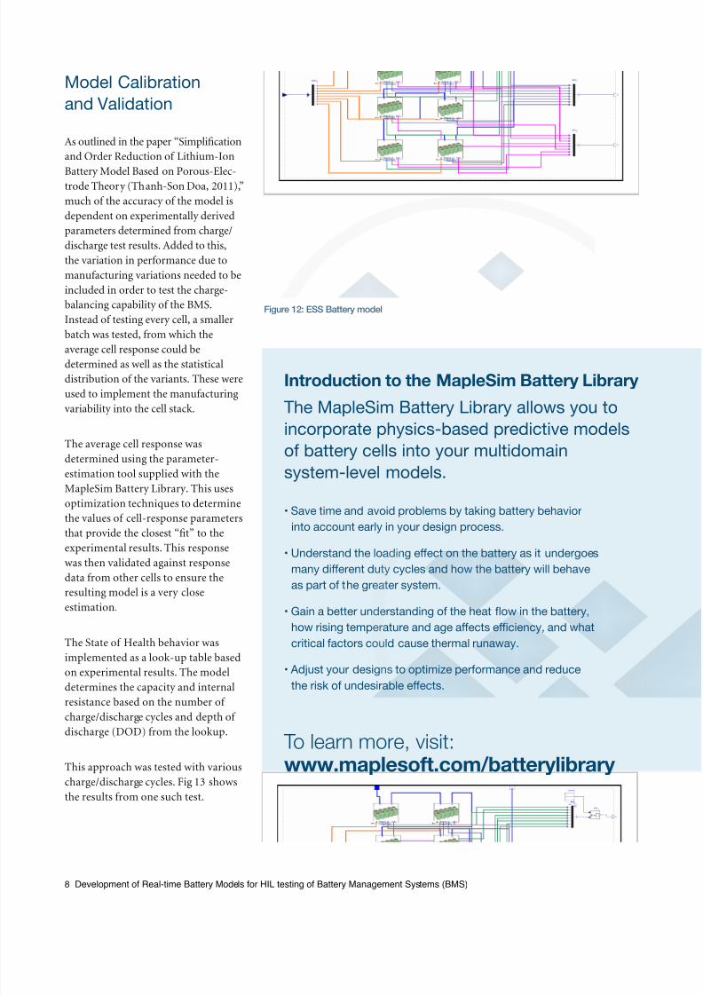
Figure 12: ESS Battery model
Introduction to the MapleSim Battery Library
The MapleSim Battery Library allows you to
incorporate physics-based predictive models
of battery cells into your multidomain
system-level models.
• Save time and avoid problems by taking battery behavior
into account early in your design process.
• Understand the loading eect on the battery as it undergoes
many dierent duty cycles and how the battery will behave
as part of the greater system.
• Gain a better understanding of the heat ow in the battery,
how rising temperature and age aects eciency, and what
critical factors could cause thermal runaway.
• Adjust your designs to optimize performance and reduce
the risk of undesirable eects.
To learn more, visit:www.maplesoft.com/batterylibrary

7/23/2019 Hiltesting Bms
http://slidepdf.com/reader/full/hiltesting-bms 9/12
Figure 14: Cell voltage distribution based on results from 48 cells
Experimental results
Max cell voltage difference = 14mV
Simula;on results
Max cell voltage difference = 13mV
9 Development of Real-time Battery Models for HIL testing of Battery Management Systems (BMS)
Figure 13: SoH simulation showing eect on battery voltage
Voltage Distribu/on for 144 Cells
Std Devia/on = 0.0039 V
Simula'on: Ba-ery voltage a4er
1, 20, 0, and 70 cyclesSimula'on: Number of cycles
Experimental results for SoH Lookup
B a t t e r y V o l t a g e [ v ]
As mentioned earlier, the variation
of cell behavior was implemented
through the use of random variants,
generated from the statistical
distribution determined from the
charge/discharge results from testing
48 cells. This was applied to all 144
cells and then compared with the real
test results. In figure 14 we see that
the maximum variance of the volt-
age from the experimental data was
14mV, while from the simulation it
was 13mV: acceptable for the purpose
of this project.
Model-code Generation
and Performance
Benchmark
Finally, the model was converted to
ANSI-C through the MapleSim Con-
nector for Simulink ®. This produces
an s-Function of the battery model
that can be tested for performance
and accuracy with a fixed-step solver
on a desktop computer in Simulink ®
before moving it to a real-time
platform. The simplest solver was
used and the performance benchshowed that the average execution
time was approximately 20 times

7/23/2019 Hiltesting Bms
http://slidepdf.com/reader/full/hiltesting-bms 10/12
faster than real-time, occupying 5.5%
of the real-time system time budget.
This demonstrates that the battery
model can easily be scaled up from
the current 144 cells, if required.
Integration of cell-packmodels into BMS
testing system
The resulting model was provided to
Control Works for integration into
the BMS testing system they were
developing for their client.
The schematic of the BMS testing
system is shown in figure 17. Thebattery model is connected to a model
of the loading system that applies
the charge/discharge current over
different duty cycles, with IO signals
connecting to the BMS interface.
The final testing station provides the
engineer with the ability to configure
the battery model (number of cells,
series/parallel, etc.) and apply a range
of tests to it.
The engineer can also go back to the
MapleSim model at any time to make
any necessary changes to the model
configuration and easily generate
the model for use on the real-time
platform. In this system, the real-time
software is National Instruments’
VeriStand™, driving a PXI real-time
system. The MapleSim Connector for
NI VeriStand Software automates the
model integration process, allowing
the engineer to produce the real-time
model quickly and reliably.
The ESS BMS Testing System from
ControlWorks is a complete turn-key
system, integrating the real-time
battery models, signal condition-
ing units, fault-insertion tools, and
standard communications protocols
(CANbus for automotive, Modbus
for industrial applications). Software
on the operator system includes NI
VeriStand™, NI TestStand™ and
MapleSim.
The system allows the engineer to
run the BMS through a range of
tests on the battery model, including
Constant Current (CC) and Constant
Voltage (CC/CV) charge/discharge
cycles, as well as Constant Power
(CP) and Constant Resistance (CR)
discharge cycles.
Results are displayed on the operator
console through NI VeriStand™ and
NI TestStand™.
10 Development of Real-time Battery Models for HIL testing of Battery Management Systems (BMS)
Figure 15: Real-Time Simulation in MATLAB/Simulink ®
Stack model was converted to Simulink® S-function for real-time simulation
Ø Total simulation time = 18,000s
Ø Solver = Euler
Ø Time-step: 0.001s
Ø Total execution time: 985s
on Intel i5 M520 2.4 GHz CPU
Ø Average execution time = 5.5% of 0.001s
Figure 16: Battery model integration into BMS test system
Charge/discharge
machine modelBa2ery pack model
Li-ion ba2ery model

7/23/2019 Hiltesting Bms
http://slidepdf.com/reader/full/hiltesting-bms 11/12
Works Cited
Battery University. (n.d.). BU-103 Global Battery Markets. Retrieved 2015, from Battery University:
http://batteryuniversity.com/learn/article/global_battery_markets
ControlWorks Inc. (2008). Control Works. Retrieved 03 31, 2015, from Control Works:
http://www.control-works.co.kr/
Maplesoft. (2014). MapleSim Battery Library. Retrieved 03 31, 2015, from Maplesoft:
http://www.maplesoft.com/products/toolboxes/battery/
Thanh-Son Dao, C. P. (2011). Simplification and Order Reduction of Lithium-Ion Battery Model Based
on Porous-Electrode Theory. Journal of Power Sources, 1-9.
Summary
For testing ESS Battery Management
Systems (BMS), the use of “virtual”
batteries is proving to be an effective
alternative to the use of real batteries.
They allow the engineer to avoid the
risks of damage to the batteries - and
subsequent costs - while testing and
optimizing the BMS design in a close-
to-reality loading environment.
Techniques for battery modeling have
advanced significantly over the years
to the point where physics-based cell
models that would have taken hours
to solve in a FE or CFD tool can now
be implemented in a system model to
predict how they would behave under
loading from complex multi-domain
systems (mechanical, electromechanical,
fluids, thermal, etc.).
Maplesoft has developed a deep
expertise in the modeling of batteries
for use in system-level studies, and
that expertise is now available
through the MapleSim Battery
Library. This provides ready-made
physics-based and equivalent-circuit
models that deliver the fidelity and
performance required for implemen-
tation on Hardware-in-the-Loop
testing platforms through MapleSim’s
optimized code generation capability.
It is for this reason that ControlWorks
– a real-time testing-systems integrator
with a lot of experience in developingBMS test stands – selected the
Maplesoft Engineering Solution team
as their model-development partner
for this project. Our client now has a
fully-configurable battery model for
testing the BMS for their ESS
products, allowing them to develop
better products, reduce project risks
and get to market faster.

7/23/2019 Hiltesting Bms
http://slidepdf.com/reader/full/hiltesting-bms 12/12
www.maplesoft.com | [email protected]
© Maplesoft, a division of Waterloo Maple Inc., 2015. Maplesoft, Maple, and MapleSim are trademarks of Waterloo Maple Inc. MATLAB and Simulink are registered trademarksof The MathWorks, Inc. LabVIEW, NI VeriStand, and National Instruments are trademarks of National Instruments. All other trademarks are the property of their respective owners.