Embed Size (px)
Citation preview

Hill Anatomotor TableOwner’s Manual
Quality and Innovation Since 1945.

Hill Laboratories has been making quality a family business since 1945.
Your new Anatomotor is built on an established Hill tradition of innovation
and value. Our reputation rests on the confidence that your Hill Table will
strengthen this legacy by providing you with solid, reliable service for many years
to come.
Congratulations!And welcome to the Hill Laboratories family.

Your Hill Laboratories table has been thoroughly tested and
inspected before shipment. All parts are guaranteed against defect
in materials for one full year from the date of purchase. During this
period, any such defect will be remedied by Hill Laboratories or by
a factory-authorized repair service at no charge. Tables damaged by
mishandling or accident will be repaired at a reasonable charge. All
correspondence should be directed to your local dealer, or when
this is not possible, to Hill Laboratories directly.
For tables beyond the warranty period, our service technicians
are standing by to serve you. They can be reached toll-free at
1-877-445-5020 from 9 am - 5 pm E.S.T., Monday through Friday.
After hours, please leave your name, phone number and a brief
description of your concern. Your call will be returned promptly the
next business day.
We appreciate your business and your confidence in our products.
Our aim is to provide you with excellent service and satisfaction for
many years to come.
President, Hill Laboratories
At Your ServiceThe Hill Laboratories Guarantee.

© Copyright 2014, Hill Laboratories
Hill Anatomotor ManualTable of Contents
Product FeaturesBasic Table Components _________________________________________________1.1Specifications __________________________________________________________1.2
Table CareCleaning your Table______________________________________________________2.1Caution and Symbol Explanation __________________________________________2.2
Basic Table FunctionsAnatomotor Controls ____________________________________________________3.1
Massage and Passive MotionBack Rollers____________________________________________________________4.1Leg Rollers _____________________________________________________________4.2Passive Exercise ________________________________________________________4.3
Using TractionHow the Traction Control Unit Works _______________________________________5.1Traction Tips ___________________________________________________________5.2Preparing the Anatomotor for Traction ______________________________________5.3Treating with Traction ____________________________________________________5.4Treating with Cervical Traction _____________________________________________5.5Arm-Shoulder Thoracic Traction ___________________________________________5.6Total Traction ___________________________________________________________5.7
Spring-Loaded Table Top . . . . . . . . . . . . . . . . . . . . . . . . . . . . . . . . . . . . .Page 19
Stationary-Top Anatomotor . . . . . . . . . . . . . . . . . . . . . . . . . . . . . . . . . .Page 19
Detailed Parts List . . . . . . . . . . . . . . . . . . . . . . . . . . . . . . . . . . . . . . . .Page 20-21
Maintenance . . . . . . . . . . . . . . . . . . . . . . . . . . . . . . . . . . . . . . . . . . . . . . .Page 22
Wiring Diagrams . . . . . . . . . . . . . . . . . . . . . . . . . . . . . . . . . . . . . . . .Pages 23-26
Traction Unit Parts/Exploded View . . . . . . . . . . . . . . . . . . . . . . . . . . .Pages 27
Index of Terms . . . . . . . . . . . . . . . . . . . . . . . . . . . . . . . . . . . . . . . . . .Pages 28-29

Product Features
1.1 Basic Table Components and Options
1.2 Specifications• Model #100: Includes Traction, Back and Leg Rollers• Model #200: Rollers Only• Optional Features: Can be added only at the time of manufacture• Height: 22” - 30” as ordered (height cannot be altered once manufactured)• Width of Table Top: Standard 21", 24" with variable speed. Stationary - 24”• Length of Table Top: 6’3”• Electrical Requirements: 110 volts - 60 cycle or 220 volts - 50 cycle if specified• Space Requirement: Model #100 - 9’; Model #200 - 7’3”Model ST2 or ST3 (Stationary) - 6’3”
• Weight (Uncrated): Model #100 - 265 lbs; Model #200 - 225 lbs.
• Shipping Weight: Model #100 - 320 lbs; Model #200 - 280 lbs.
2© Copyright 2014, Hill Laboratories
1
2
34
5
6
7
9
11
10
12
13 14
4
10
1516
17
1. Semi-pneumatic back rollers2. Filler block3. Top pad4. Pillow5. Leg rollers6. Foot pad7. Traction Control Unit8. Counter Traction Bracket9. Counter Traction Unit10. Back roller adjustment handles
11. Control Panel (controls time, heat,vibration, tilt and speed options)
12. Leg roller bracket13. Thoracic harness14. Traction harnesses15. Gripper bar16. Ankle harness17. Cervical traction device18. Head Halter (special order)***Traction Stool (not shown)
18
See pages 20 and 21 for a detailed parts list.
8

Table Care2.1 Cleaning your Table
Hill table upholstery may be cleaned with Hill Laboratories' Vinyl andLeather Cleaner or any household dishwashing liquid mixed with water. Hillalso offers Protex™ Disinfectant Spray and wipes to protect againstpathogens, such as MRSA, HIV, Staph and the H1N1 Swine Flu Virus. Manystubborn stains can be removed by applying 91% rubbing alcohol (isopropylalcohol) to the stain and wiping with a dry, soft, lint-free cotton cloth, towel orsoft bristle brush. Be sure to rinse thoroughly with water.
Caution: Some solvents are highly flammable; do not use near open flameor intense heat. Wear rubber gloves during all cleaning activities. Whencleaning other parts of your table (besides upholstery) use only nonabrasivehousehold detergents and water.
2.2 Caution and Symbol ExplanationCaution:Children should never be left alone in a room with the table butshould always be accompanied by an adult.
Caution: Always unplug the table before performing any maintenance.
Caution: Check table once a year to make sure all internal and externalbolts are secure.
Caution: The power cord should be located to avoid risk of tripping orhaving objects rolled over or placed on top of it. Damaged cords shouldbe replaced with another of hospital grade.
Caution:Grounding reliability can only be achieved when connected to anequivalent receptacle marked hospital only or hospital grade.
Symbols - Each of the symbols below are used in your table labeling. An explanation of each is below.
3© Copyright 2014, Hill Laboratories
~Attention Symbol consult accompanying
documents
Dangerous Voltage Symbol
Type BF AppliedPart Symbol
GroundSymbol
AlternatingCurrentSymbol
Don’t TouchSymbol

Basic Table FunctionsNote: See a full demonstration video at www.HillLabs.com/Anatomotor-Video
3.1 Anatomotor ControlsThe follow section describes each of the Anatomotor controls with a brief explanationof use. Thoroughly familiarize yourself with the controls before operating the table.
Note: Not all models are equipped with all the control features listed below.
1.
Heat Button (Optional)The heat control switch activates a metal strip heater located in the frame belowthe rollers. A mild heat is radiated up through the rollers to the top pad where it averagesapproximately 105°F (40° C), thus providing a soothing warmth to the spinal area. Theheating unit takes approximately 5 to 10 minutes to warm up and may be left on all day, ifso desired. The heat’s effectiveness is reduced if turned on and off for each patient.
2. Tilt Top (Optional) (Indicator Light)The Tilt-Top Light comes on when the Tilt-Top is in use. To raise the Tilt Top:1. Remove the filler block. Failure to do so will re-sult in damage to the table.
2. Set the timer to the "off" position.
3. Push the cervical-lumbar switch to "lumbar" sothat the table top glides to the foot end. Thetilt top will not raise unless it is in this position.
4. Press the foot pedal control to the desired position.The right side will raise the top; left side will lower.
4© Copyright 2014, Hill Laboratories
1 2 3 4 57
1. Heat Button2. Tilt Top (indicator light)3. Vibration Button4. Cervical-OFF-Lumbar Switch
5. Timer6. Upper and Lower Roller Adjustment7. Variable Speed Dial
6

5. The indicator light will illuminate as soon as the tilt top is activated. Due to internalsafety switches, the table top will not glide back and forth until the top is com-pletely lowered and the indicator light is out.
6. The timer must be reset in order for the table top to glide back and forth.
Note: It is often more comfortable if the patient turns to their side, knees slightlybent, before activating the tilt top.
3. Vibration Button (Optional)The vibrator unit administers a soothing vibration at a single speed of 3200 cyclesper minute. The vibrator is located on the inside frame so that most of the vibrationis felt through the rollers. Occasionally, excessive vibration noise may occur due tosome types of flooring. If you experience this problem, place rubber pads or smallpieces of carpeting under each foot of the table.
4. Cervical-Lumbar SwitchThe Cervical-Lumbar Switch controls where the gliding top stops at the end of atreatment cycle. With the timer off and set to “Cervical”, the table top will stop at thecervical end of the table. Similarly, when set to “Lumbar” the table top will stop at thelumbar end. When used properly, the Cervical-Lumbar Switch ensures that a patientis never left under constant traction pull at the end of a treatment.
Setting the Cervical-Lumbar Switch to the "OFF" position will stop the table instantly.It also allows the operator to leave the patient in constant traction when desired.When using only the rollers, the switch may be turned to either the cervical or lumbarposition. Both of these are considered "ON" positions. The table will not glide backand forth without both the timer and the Cervical-Lumbar Switch placed in an "ON"position. Tables with rollers only will usually have an "ON/OFF" switch instead of theCervical-Lumbar Switch.
5. TimerThe timer sets the treatment time for the patient. The timer can be set from 1 to 30minutes by turning the dial clockwise to the appropriate number. The average treat-ment time is 7 to 10 minutes. A bell will ring at the end of treatment. The operatormay stop the table before the timer rings by turning the timer to the "OFF" position.This will not harm the timer in any way.
6. Upper and Lower Roller ControlsThe back roller handles raise and lower thethoracic and lumbar rollers. The rollers arelocked in place by turning the handlecounter-clockwise to the higher numbers.When the desired roller height is reached,move the Lock Lever to the left (photo 1, A)and while holding it there, release your handfrom the roller handle to lock (photo 1, B). Tolower the rollers, push the handle toward thehigher numbers without touching the locklever, then return the handle to the down po-sition. (Refer to back roller section for detailed information.)
5© Copyright 2014, Hill Laboratories
photo 1
First, releasethe handle. Then,release the lock.
A
B
7. Variable Speed Control (Optional)The speed control dial can be turned to slow the movement of the table top from4.5 to 15 seconds. This allows the traction to be applied for a longer time period.When treating with rollers only, the speed control should be set on 4.5 seconds.
Massage and Passive MotionA Gliding Top
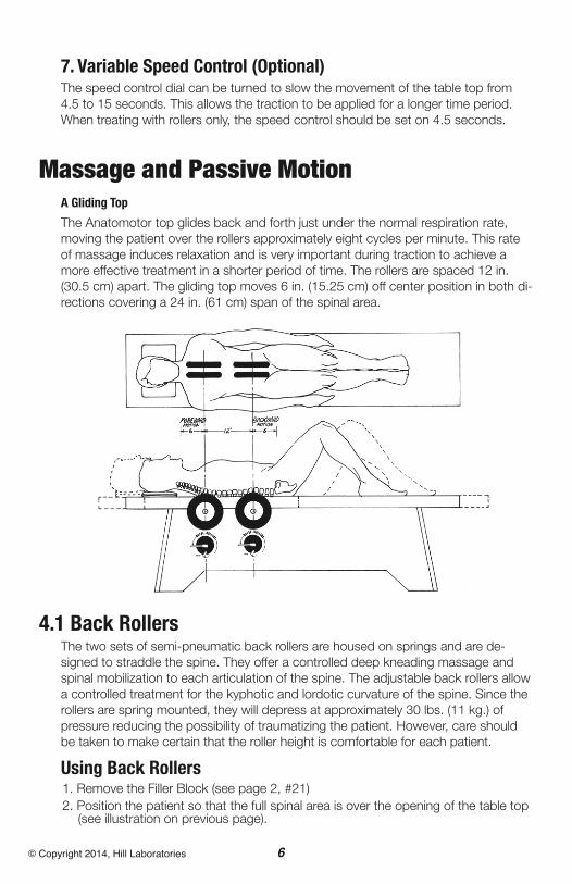
The Anatomotor top glides back and forth just under the normal respiration rate,moving the patient over the rollers approximately eight cycles per minute. This rateof massage induces relaxation and is very important during traction to achieve amore effective treatment in a shorter period of time. The rollers are spaced 12 in.(30.5 cm) apart. The gliding top moves 6 in. (15.25 cm) off center position in both di-rections covering a 24 in. (61 cm) span of the spinal area.
4.1 Back RollersThe two sets of semi-pneumatic back rollers are housed on springs and are de-signed to straddle the spine. They offer a controlled deep kneading massage andspinal mobilization to each articulation of the spine. The adjustable back rollers allowa controlled treatment for the kyphotic and lordotic curvature of the spine. Since therollers are spring mounted, they will depress at approximately 30 lbs. (11 kg.) ofpressure reducing the possibility of traumatizing the patient. However, care shouldbe taken to make certain that the roller height is comfortable for each patient.
Using Back Rollers1. Remove the Filler Block (see page 2, #21)2. Position the patient so that the full spinal area is over the opening of the table top(see illustration on previous page).
6© Copyright 2014, Hill Laboratories

7© Copyright 2014, Hill Laboratories
2. It is generally recommended that the patientflex his or her legs while keeping his or herfeet flat on the foot pad. This position flattensthe normal lumbar curvature, thus providinga more equalized roller pressure in that area.
3. Set the timer and switch to the "on" position(either cervical or lumbar).
4. The roller settings can be determined by the feeling of resistance through theback roller handle. As the patient is gliding back and forth, raise the rollers until afirm resistance is felt, then lock in position as described in previous section “BasicTable Functions, Upper and Lower Roller Controls”. Roller settings will vary ac-cording to a patient's tolerance and condition.
5. Determining where the back rollers are treating the patient is easy. While the tableis in motion, locate the center axis of the roller handle and follow straight up.
6. The patient may be positioned higher or lower on the table top depending on hisor her height and where the treatment is required. The position of the back rollersis very important when using traction (see “Using Traction”).
7. The numbers on the Roller Control Dials are used as reference to aid in maintain-ing and recording uniform levels of treatment. Each increase in number repre-sents 1/6 in. (0.4 cm) height adjustment.
4.2 Leg RollersThe reciprocating action of the Anatomotortop also provides motion for leg massageand passive exercise to the knees and hips.The leg rollers can be placed into any oneof the four positions of the leg roller brackets.The various positions are designed to ac-commodate the different heights of patientsand to massage different areas of the legs.As with any treatment, the leg massageshould be used with the doctors discretion.
Caution: Leg rollers should be avoided withpatients who have severe varicosity or phlebitis.
Using Leg Roller Massage1. With the timer off, set the switch to thecervical position.
2. Position the patient comfortably on thetable top (shoes removed).
3. Place the leg rollers beneath the patient's legs in the desired treatment area. Forthe average height patient, position #2 is for the calf area; Position #4 is for theupper thigh area.
4. Center the rubber leg rollers on the bar and rest the patient's legs on top of the rollers.
5. Place filler block, firm side up, under the heels of the patient. This will result in amilder massage to the leg area.
photo 2
photo 3
8© Copyright 2014, Hill Laboratories
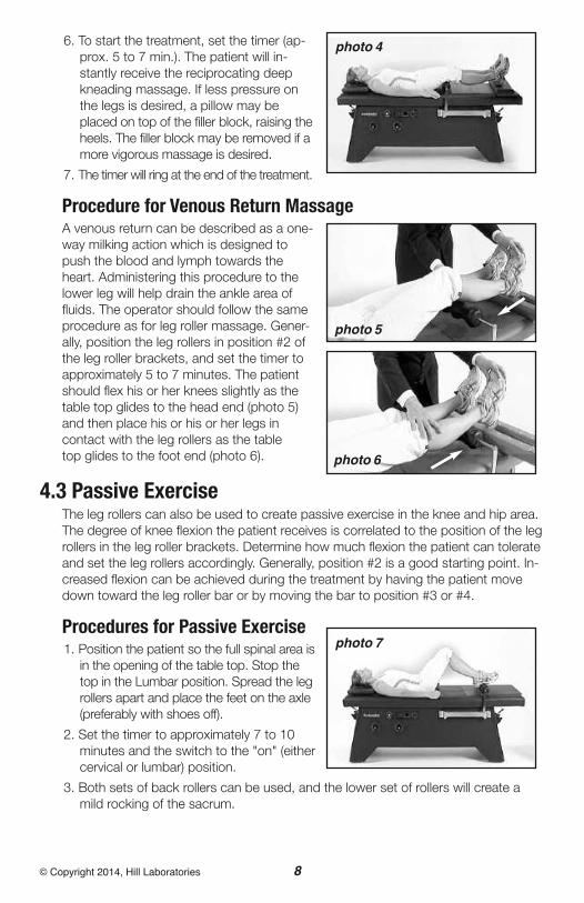
6. To start the treatment, set the timer (ap-prox. 5 to 7 min.). The patient will in-stantly receive the reciprocating deepkneading massage. If less pressure onthe legs is desired, a pillow may beplaced on top of the filler block, raising theheels. The filler block may be removed if amore vigorous massage is desired.
7. The timer will ring at the end of the treatment.
Procedure for Venous Return MassageA venous return can be described as a one-way milking action which is designed topush the blood and lymph towards theheart. Administering this procedure to thelower leg will help drain the ankle area offluids. The operator should follow the sameprocedure as for leg roller massage. Gener-ally, position the leg rollers in position #2 ofthe leg roller brackets, and set the timer toapproximately 5 to 7 minutes. The patientshould flex his or her knees slightly as thetable top glides to the head end (photo 5)and then place his or his or her legs incontact with the leg rollers as the tabletop glides to the foot end (photo 6).
4.3 Passive ExerciseThe leg rollers can also be used to create passive exercise in the knee and hip area.The degree of knee flexion the patient receives is correlated to the position of the legrollers in the leg roller brackets. Determine how much flexion the patient can tolerateand set the leg rollers accordingly. Generally, position #2 is a good starting point. In-creased flexion can be achieved during the treatment by having the patient movedown toward the leg roller bar or by moving the bar to position #3 or #4.
Procedures for Passive Exercise1. Position the patient so the full spinal area isin the opening of the table top. Stop thetop in the Lumbar position. Spread the legrollers apart and place the feet on the axle(preferably with shoes off).
2. Set the timer to approximately 7 to 10minutes and the switch to the "on" (eithercervical or lumbar) position.
3. Both sets of back rollers can be used, and the lower set of rollers will create amild rocking of the sacrum.
photo 4
photo 6
photo 5
photo 7

9© Copyright 2014, Hill Laboratories
Using Traction5.1 How the Traction Control Unit Works
The Hill Anatomotor traction table providesboth intermittent and constant traction. Thetraction control unit works on the principle ofa friction disc brake. The harness is attachedto the patient and the traction control unit.Intermittent traction occurs through the re-ciprocating motion of the gliding top. The topmoves against the controlled friction createdby the traction control unit. Constant tractionis achieved by turning the cervical-lumbarswitch off during the pull cycle of traction.
Regulating Traction PullTo regulate tension, turn the calibratedhand dial clockwise. The top number of thedial corresponding to the pointer is theamount of traction being applied (photo 8, A).Due to the return springs on each side of thetraction unit, there is a built-in resistance factorof approximately 7 to 10 lbs. (3 to 4 kg.). There-fore, this is the minimum pull you can achieve.
The hand dial is self-locking to the positionyou select. As you dial to the high numbers, the hand dial will become slightly harderto turn, which also indicates increased pull is being applied.
Important! Before treating any patient, make absolutely sure that the hand dial isturned all the way down, counter-clockwise, to 10 LBS. This assures that each pa-tient’s treatment will start at the minimum pull. ALSO, the dial may be adjusted dur-ing a treatment BUT PREFERABLY ONLY IN THE REST CYCLE.
5.2 Traction Tips
The Effective Way to Determine Traction PullThe most effective way to administer traction is to feel by hand the joint or spinalarea to which traction is being applied. While palpating the area, the operator caneasily feel joint separation and muscle structure. After determining the desired pullfor each individual patient, the dialed number can be recorded and used as a refer-ence point for subsequent treatments.
Reduce Traction Treatment Time with Back RollersTo achieve good results during traction, it is important to have the patient physicallyand mentally relaxed. Therefore, the combination of back rollers during traction of-fers many benefits and advantages including the reduction of treatment time to ap-proximately 10 to 12 minutes.
photo 8
A

10© Copyright 2014, Hill Laboratories
Other Factors to Consider when Using Traction1. Patient weight and muscle structure will alter the amount of pull required.
2. Back rollers relax muscles and reduce the need for the traction to overcomemuch of the muscle tautness.
3. The back rollers will decrease the amount of friction of the body weight on thesurface of the table top. Therefore, when the back rollers are used in conjunctionwith traction, less poundage is required.
4. Lumbar back rollers can create a pelvic tilt or lumbar flexion when using lumbar traction.
5. Various traction angles and the position of the patient (such as placing legs on astool for lumbar traction) will often change the amount of traction required.
Intermittent vs. Constant TractionIt is important to determine when to use intermittent traction versus constant trac-tion. Because intermittent traction increases circulation, it will often aggravate anacute condition. Therefore, if traction is desired for an acute patient, most doctorsrecommend that constant traction be applied. The first treatment should be of shortduration and low poundage. For the variable-speed model, the speed can be set fora longer cycle at pull and rest.
5.3 Preparing the Anatomotor for TractionPrior to administering any form of traction, the following steps must be followed.
1. Set the Timer to “OFF” (page 4, #5) and set the Cervical-Lumbar Switch in the opposite di-rection of the Traction Control Unit placement. For example, to place the Traction Unit at thelumbar (or foot) end of the table, set the Cervical-Lumbar Switch (page 4, #4) to “CERVI-CAL” so that the table top will automatically stop at the cervical (or head) end. This will allowplacement of the traction unit at the foot-end.Similarly, set the C/L switch to “LUMBAR” ifthe traction unit is to be placed at the cervicalend.
2. By pushing up on the lever (photo 9, A) theTraction Control Unit can now be pushedsquarely into the Base Plate. There is no needto push down on the lever lock because it isself-locking. Important! Ensure that the Hand Dial is set atthe minimum weight.
3. With the Timer still in the OFF position, set theCervical-Lumbar Switch to correspond withthe traction unit’s present position. The top willthen move and stop next to the traction unit.
4. If countertraction is needed, consult followingsection “Treating with Traction” then insert theCountertraction Unit into the CountertractionBracket as shown in photo 10. The Countertraction Unit and the Traction Control Unitshould never be positioned at the same end of the table at the same time.
photo 9
A
photo 10
11© Copyright 2014, Hill Laboratories
5.4 Treating with Traction
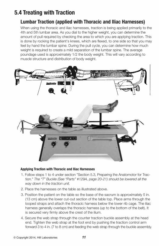
Lumbar Traction (applied with Thoracic and Iliac Harnesses)When using the thoracic and iliac harnesses, traction is being applied primarily to the4th and 5th lumbar area. As you dial to the higher weight, you can determine theamount of pull required by checking the area to which you are applying traction. Thisis done by rocking the patient's knees, which are flexed, to one side so that you mayfeel by hand the lumbar spine. During the pull cycle, you can determine how muchweight is required to create a mild separation of the lumbar spine. The averagepoundage used is approximately 1/2 the body weight. This will vary according tomuscle structure and distribution of body weight.
Applying Traction with Thoracic and Iliac Harnesses
1. Follow steps 1 to 4 under section "Section 5.3, Preparing the Anatomotor for Trac-tion." The “T” Buckle (See “Parts” #129A, page 20-21) should be lowered all theway down in the traction unit.
2. Place the harnesses on the table as illustrated above.
3. Position the patient on the table so the base of the sacrum is approximately 5 in.(13 cm) above the lower cut-out section of the table top. Place arms through thelooped straps and attach the thoracic harness below the lower rib cage. The iliacharness generally overlaps the thoracic harness (up to the bottom of the belt). Itis secured very firmly above the crest of the ilium.
4. Secure the web strap through the counter traction buckle assembly at the headend. Tighten the web strap at the foot end by pushing the traction control armforward 3 to 4 in. (7 to 8 cm) and feeding the web strap through the buckle assembly.

12© Copyright 2014, Hill Laboratories
It is not necessary to push down on the flap of the buckle as it is self-locking.
5. The patient's legs should be flexed to flatten the lumbar curve. Use of a flexionstool is often more desirable for reducing the lumbar curve.
6. Make certain the traction control unit is dialed to the minimum weight. With theswitch in the lumbar position, set the timer to the desired time (approximately10 to 12 minutes). The table will start instantly.
7. If not contraindicated, the rollers should now be set into position. They are veryeffective for relaxing muscles and creating flexion of the lumbar spine during thetraction pull cycle. The rollers should not be used when constant traction is desired.
8. To set poundage, dial the poundage gauge during the rest cycle. The top return-ing toward the traction arm is referred to as the rest cycle. The top moving awayfrom the traction arm is referred to as the pull cycle.
9. Traction should be applied gradually during the first several rest cycles of the re-ciprocating top.
Important! At no time should the traction control unit be set to the full poundagedesired in the first pull cycle.
10. When the timer rings, the table will stop out of the traction pull cycle.
11. When constant traction is required and after the desired amount of pull hasbeen determined, place the switch to the "off" position when the table top hasmoved approximately 3/4 of the way during the pull cycle. The timer can be setfor the desired constant pull time. When the timer rings, press the switch to "lum-bar". The top will then return to the relaxed traction position.
12. At the end of the traction treatment, turn the traction dial to the minimum weightand lower the rollers. Release the web straps from both buckle assemblies andremove the harnesses from the patient.
13. In order for the patients muscle structure to readjust, it is recommended that heor she rest on the Anatomotor for 1 to 2 minutes. Walking slowly will also helpbalance the muscle structure.
Unilateral Lumbar TractionTo apply unilateral traction with the iliac harness, replace the iliac spreader bar withthe "D" ring strap (see “Parts”, #110, page 20-21). The "D" ring strap can be attachedto either side of the harness in order to create pull on just one side of the pelvic region.Start with low poundage and work up to desired level of pull.
Lumbar or Buck’s Traction (applied with ankle harnesses)The ankle harnesses are also used for lumbar traction. They are designed to applytraction to the lumbar spine as well as the full group of lumbar muscles. Doctorsoften recommend this type of traction for the patient and with sciatica when pull isdesired on just one leg. Traction to the knee and hip area can also be achieved. Ap-proximately 1/4 to 1/3 of the body weight is required with both legs in traction; 1/8to 1/4 of the body weight with single leg traction. The recommended treatment timeis 7 to 10 minutes.

13© Copyright 2014, Hill Laboratories
Applying Traction with Ankle Harnesses
1. Follow steps 1 to 4 under the section "Section 5.3, Preparing the Anatomotor forTraction".
2. Place the harnesses on the table as illustrated above.
3. Position the patient on the table so that the base of the sacrum is 5 in. (13 cm)above the lower cut-out section of the table top. Place the arms through thelooped straps and attach the thoracic harness below the rib cage. Fasten theankle harnesses, making certain the velcro is pressed firmly together. (To in-crease patient comfort or, for patients with smaller ankles, insert the foam padsthat came with your table into the ankle harnesses).
4. At the foot-end, adjust the T-Buckle to the lowest height and feed the web strapthrough the buckle assembly (see “A”, photo above). Tighten the web strap bypushing the traction control arm towards the table about 3 to 4 in. (7 to 8 cm.)while feeding the web strap through the buckle assembly.
5. To eliminate direct pull on the knees, place the filler block under the knees as il-lustrated. Increasing the knee flexion with additional pillows will change theangle of pull and, thus, increase the traction pull even if the calibrated dial hasnot been increased.
6. Make certain the traction control unit is dialed to the minimum weight. With theswitch in lumbar position, set the timer to the desired time (approximately 7 to10 min.). The table will start instantly.
7. If not contraindicated, the back rollers should now be set into position. Constanttraction is not recommended when using the ankle harnesses.
8. To set the poundage, dial the gauge during the rest cycle. The top returning to-ward the traction arm is referred to as the rest cycle. The top moving away fromthe traction arm is referred to as the pull cycle.
A

14© Copyright 2014, Hill Laboratories
9. Traction should be applied gradually during several rest cycles of the recipro-cating top, and desired pull should be checked by palpating the area which isbeing tractioned.
10. When the timer rings, the table will stop out of the traction pull cycle.
Single Leg TractionSingle leg traction is often administered when treating sciatica. Although the pull iscommonly administered to the short, painful leg, such treatment is not always therule. Careful diagnosis of x-rays, muscle testing, etc. should be your guide.
1. Apply both ankle harnesses, as in bilat-eral traction, and determine the amountof pull that is required for the patient(usually 1/4 to 1/3 of the body weight).
2. After 1 to 2 minutes of bilateral traction,decrease the traction pull to approxi-mately 1/8 to 1/4 of the body weight.
3. Switch to single leg traction by holdingthe traction arm while it is returning tothe rest cycle. Remove the spring clip on the ankle harness from the "D" ringstrap releasing traction from the one leg (photo 11).
4. Prior to the end of the treatment it is recommended that you switch back tobilateral traction for approximately 1 to 2 minutes. This will help equalize themuscle structure.
Direct Knee TractionTo achieve direct pull to the knee area, remove the filler block. Mobilization tech-niques can be performed under constant traction. Stop the table top near the endof the pull cycle.
5.5 Treating with Cervical Traction
The Traction Control UnitTo administer cervical traction, the Traction Control Unit needs to be inserted atthe head-end of the table. Remove the pillow and make sure your poundage isturned to the lowest setting (photo 8). The Cervical Traction Device fits into thebracket on the table top (photo 12). Movethe Lumbar-Cervical Switch to the cervicalposition and insert the short T-buckle intothe Traction Control Unit. With the insertpad facing the ceiling, position the patient’soccipital region into the upper inside ridge ofthe cradle support. Tighten the tension knobuntil the patient feels a slight, inward pres-sure (photo 13). Gently secure the foreheadstrap. Pull the web strap firmly through theT-buckle assembly (photo 14). Set the timer
photo 11
photo 12

15© Copyright 2014, Hill Laboratories
to 7-10 minutes. Adjust the upper set ofrollers to relax the thoracic area during trac-tion. Adjusting the variable speed to 7 or 8seconds of pull-and-release, is recommendedfor patient comfort. As the table returns to therelaxed position, slowly increase the poundage.Usually 20-40 pounds should be sufficient(the Cervical Device has a built in returnspring of 10 pounds. This means that thepatient experiences ZERO POUNDS of pullwhen the traction unit is set at 10 poundsand similarly, ten pounds less than the dialreads at each point). You can palpate thecervical area and feel a slight separation.When treatment has ended, treatment willstop in the cervical position. Release thetension on the T-buckle and loosen the ten-sion knobs on the cradle support. Assist thepatient to a seated position.
The Head Halter (option)1. Follow steps 1 to 4 under "Section 5.3, Preparing the Anatomotor for Traction".Make certain the hand dial on the traction unit is set to the minimum amount.If your table has variable speed, turn the speed dial to 6-8 seconds.
2. Pull out on the Traction Adjustment Handle (F) and raise or lower the "T" buckleassembly in the traction arm according to the desired angle of pull (usually thehighest level) and then release the self-locking handle (F).
3. With the head halter attached, place the hook of the compensator up through theeye bolt as illustrated.
4. Position the patient so that thetop of his or her head is approx-imately 7 in. (18 cm) down fromthe head end of the table top.Cover one of the foam padswith facial tissue and insert it inthe chin pad (A). Place pad (A)on the patient's chin and centerthe seam of the head halter inthe middle of the chin. The vel-cro closure can be adjusted tocontour the chin. Have the pa-tient hold pad (A) in place whileproceeding to step 5.
5. Place the tissue over occipitalpad. Hold pad where the twostraps (C) join it. Place pad justbelow the occiput and hook the slide buckle of strap (C) to the clip on pad (A).Tighten firmly by pulling straps (C) equally (photo 16).
photo 13
photo 14
F
E
D
D
E
A
C
C

16© Copyright 2014, Hill Laboratories
6. Stand, as pictured (photo 17), pushingup on the traction control arm about 1/2the distance to the table top. This willplace slack in the head halter straps.Equally tighten both occipital straps (D)as much as possible by pulling thestraps toward you. The head haltershould now have slack in the chin strap(A) and tension on the occipital strap (D).This important step takes the pressureoff the chin and transfers it to the occiput.
7. Allow the traction control unit arm tomove back to the normal position. If thestraps have been adjusted equally, thebow spring should appear parallel to thetable top. The patient should feel a slighttension of the head halter. If any saggingof the bow spring occurs, tighten ad-justing straps (E).
8. Make certain the Cervical-Lumbar switchis in the "cervical" position and the trac-tion control dial is set to the minimum (asfar counter-clockwise as possible). Thetable will start when the timer is set.Note: Supporting the head with thefolded pillow will avoid sudden lifting orjerking of the head during traction.
9. Increase traction pull to the desired amount. Position the upper set of back rollersto relax the muscles and provide rolling traction to the affected area.
10. When the traction time is terminated, unhook strap (C) as illustrated. Allow thepatient to rest on the table 1 to 2 minutes after the treatment.
11. After the head halter is removed, lengthen straps (D) in order to prepare the hal-ter for the next patient.
Treatment Variations1. Constant traction may be obtained by stopping the table top at the extreme endof the traction pull (foot end). Mobilization or manipulation techniques can also beperformed.
2. If desiring an improvement of rotarymotion, the patient can easily rotate hisor her head to the right or left during thetraction pull cycle (photo 18).
3. When more traction pull is desired onone side of the neck (i.e. torticollis),tighten strap (D) on just one side of thehead halter. The bow spring will lookslanted.
photo 15
photo 16
photo 17Push arm
photo 18

17© Copyright 2014, Hill Laboratories
5.6 Arm-Shoulder Thoracic Traction The gripper bar is used to administer traction to the upper dorsal area. The one setof back rollers (usually lower set) can be used in conjunction with this type of tractionto treat the area between the scapulae. The rollers will aid in the expansion of the ribcage and will help respiration. Start with the table top in the cervical position. Traction: approximately 1/4 body weight. Treatment time: 7 to 10 minutes.
Bilateral Dorsal Pull1. Follow steps 1 to 4 under section "Section 5.3, Preparing the Anatomotor for Trac-tion".
2. Raise and secure the "T" buckle assembly (see Parts Description, 129A) in thetraction unit (middle to upper position is advisable for patient comfort). Insert theweb strap of the gripper bar through the buckle assembly.
3. Position the patient so that his or her arms are fully extended when grasping thegripper bar (see illustration).
4. The switch should be in the "cervical" position and the traction weight set at theminimum. Set the timer to start treatment.
5. The lumbar rollers should now be raised to treat the thoracic area. (note: this isdue to the fact that the patient is positioned further down on the table top.)
6. Gradually dial the traction weight according to the patient's needs.
7. To aid respiration, have the patient inhale during the traction pull cycle. As therollers are moving to the dorsal area, they will help expand the chest area. Havethe patient exhale during the traction rest cycle as therollers are moving to the lumbar area.
Unilateral Dorsal PullUnilateral dorsal traction can be very beneficial to helpcounteract the curve of scoliosis. Follow the same proce-dure as previously described. Turn the traction weightdown slightly and slide the gripper bar strap to one side(the concave side).
18© Copyright 2014, Hill Laboratories
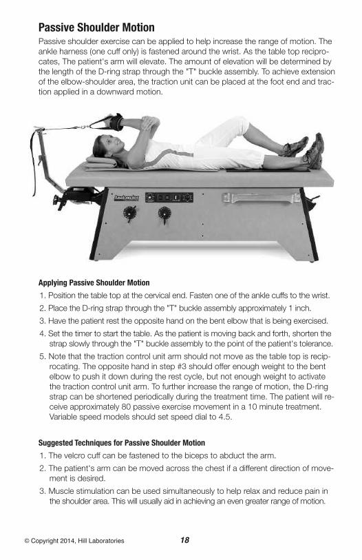
Passive Shoulder MotionPassive shoulder exercise can be applied to help increase the range of motion. Theankle harness (one cuff only) is fastened around the wrist. As the table top recipro-cates, The patient's arm will elevate. The amount of elevation will be determined bythe length of the D-ring strap through the "T" buckle assembly. To achieve extensionof the elbow-shoulder area, the traction unit can be placed at the foot end and trac-tion applied in a downward motion.
Applying Passive Shoulder Motion
1. Position the table top at the cervical end. Fasten one of the ankle cuffs to the wrist.
2. Place the D-ring strap through the "T" buckle assembly approximately 1 inch.
3. Have the patient rest the opposite hand on the bent elbow that is being exercised.
4. Set the timer to start the table. As the patient is moving back and forth, shorten thestrap slowly through the "T" buckle assembly to the point of the patient's tolerance.
5. Note that the traction control unit arm should not move as the table top is recip-rocating. The opposite hand in step #3 should offer enough weight to the bentelbow to push it down during the rest cycle, but not enough weight to activatethe traction control unit arm. To further increase the range of motion, the D-ringstrap can be shortened periodically during the treatment time. The patient will re-ceive approximately 80 passive exercise movement in a 10 minute treatment.Variable speed models should set speed dial to 4.5.
Suggested Techniques for Passive Shoulder Motion
1. The velcro cuff can be fastened to the biceps to abduct the arm.
2. The patient's arm can be moved across the chest if a different direction of move-ment is desired.
3. Muscle stimulation can be used simultaneously to help relax and reduce pain inthe shoulder area. This will usually aid in achieving an even greater range of motion.
19© Copyright 2014, Hill Laboratories
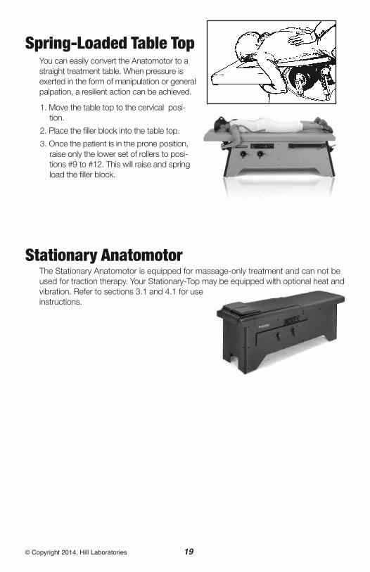
Spring-Loaded Table TopYou can easily convert the Anatomotor to astraight treatment table. When pressure isexerted in the form of manipulation or generalpalpation, a resilient action can be achieved.
1. Move the table top to the cervical posi-tion.
2. Place the filler block into the table top.
3. Once the patient is in the prone position,raise only the lower set of rollers to posi-tions #9 to #12. This will raise and springload the filler block.
Stationary AnatomotorThe Stationary Anatomotor is equipped for massage-only treatment and can not beused for traction therapy. Your Stationary-Top may be equipped with optional heat andvibration. Refer to sections 3.1 and 4.1 for useinstructions.
20© Copyright 2014, Hill Laboratories
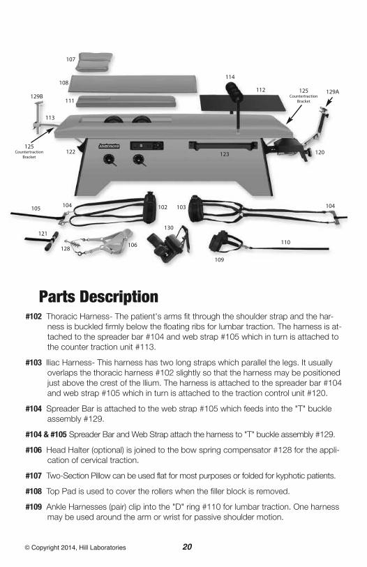
Parts Description#102 Thoracic Harness- The patient's arms fit through the shoulder strap and the har-
ness is buckled firmly below the floating ribs for lumbar traction. The harness is at-tached to the spreader bar #104 and web strap #105 which in turn is attached tothe counter traction unit #113.
#103 Iliac Harness- This harness has two long straps which parallel the legs. It usuallyoverlaps the thoracic harness #102 slightly so that the harness may be positionedjust above the crest of the Ilium. The harness is attached to the spreader bar #104and web strap #105 which in turn is attached to the traction control unit #120.
#104 Spreader Bar is attached to the web strap #105 which feeds into the "T" buckleassembly #129.
#104 & #105 Spreader Bar and Web Strap attach the harness to "T" buckle assembly #129.
#106 Head Halter (optional) is joined to the bow spring compensator #128 for the appli-cation of cervical traction.
#107 Two-Section Pillow can be used flat for most purposes or folded for kyphotic patients.
#108 Top Pad is used to cover the rollers when the filler block is removed.
#109 Ankle Harnesses (pair) clip into the "D" ring #110 for lumbar traction. One harnessmay be used around the arm or wrist for passive shoulder motion.
107
108
129B129A
111
112
114
125Countertraction
Bracket
125Countertraction
Bracket
113
120122
102 103 104
110
109
130
104105
121
128106
123
21© Copyright 2014, Hill Laboratories
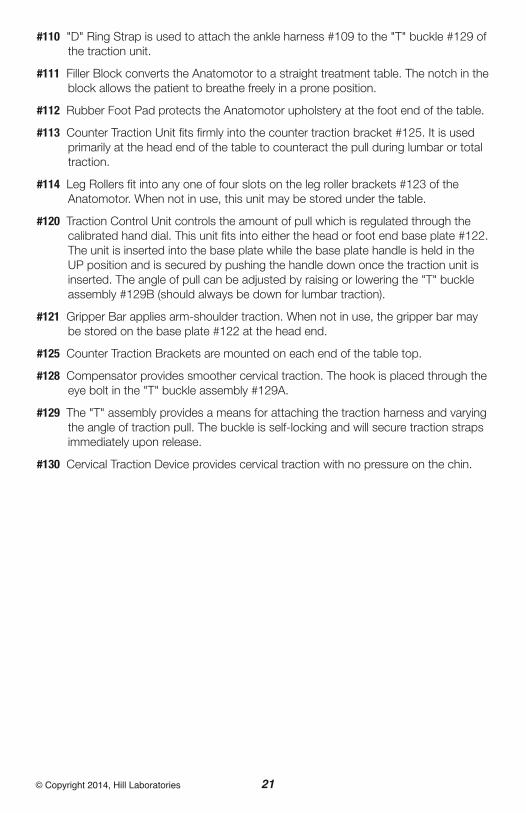
#110 "D" Ring Strap is used to attach the ankle harness #109 to the "T" buckle #129 ofthe traction unit.
#111 Filler Block converts the Anatomotor to a straight treatment table. The notch in theblock allows the patient to breathe freely in a prone position.
#112 Rubber Foot Pad protects the Anatomotor upholstery at the foot end of the table.
#113 Counter Traction Unit fits firmly into the counter traction bracket #125. It is usedprimarily at the head end of the table to counteract the pull during lumbar or totaltraction.
#114 Leg Rollers fit into any one of four slots on the leg roller brackets #123 of theAnatomotor. When not in use, this unit may be stored under the table.
#120 Traction Control Unit controls the amount of pull which is regulated through thecalibrated hand dial. This unit fits into either the head or foot end base plate #122.The unit is inserted into the base plate while the base plate handle is held in theUP position and is secured by pushing the handle down once the traction unit isinserted. The angle of pull can be adjusted by raising or lowering the "T" buckleassembly #129B (should always be down for lumbar traction).
#121 Gripper Bar applies arm-shoulder traction. When not in use, the gripper bar maybe stored on the base plate #122 at the head end.
#125 Counter Traction Brackets are mounted on each end of the table top.
#128 Compensator provides smoother cervical traction. The hook is placed through theeye bolt in the "T" buckle assembly #129A.
#129 The "T" assembly provides a means for attaching the traction harness and varyingthe angle of traction pull. The buckle is self-locking and will secure traction strapsimmediately upon release.
#130 Cervical Traction Device provides cervical traction with no pressure on the chin.

22© Copyright 2014, Hill Laboratories
MaintenanceYour Anatomotor is practically mainte-nance free and will typically deliveryears of service with little to no up-keep. Below, however, are a fewbasic instructions to assure that yourAnatomotor will always run smoothly.
1. Always unplug the table before any servicing,cleaning or maintenance.
2. Remove the top of the table. A regular top hasfour wing nuts directly under the ends of the eachside (see drawing above “A,B,D,E). A tilt-top tablehas three wing nuts; two at the foot end (D and Ein drawing) and one under the middle of the top,just inside the roller opening (“C”).
2. Every 2 to 3 years your Anatomotor should beoiled. With top removed, apply 2 or 3 drops ofcommon household oil to each side of all of thesix casters that the table top glides back and forthon (see fig. 1).
3. Remove the caps on either side of the motor(caps will be yellow or red, see ‘A’, fig. 2). Removethe caps with a screwdriver and then with yourhousehold oil, put approximately 5 drops intoeach side.
4. Apply 3 or 4 drops of oil to the Push-Rod Bushing(see ‘B’ fig. 2).
5. Also apply a few drops of oil to the axles of theBack Rollers (see fig. 3)
6. Vacuum the inside of your Anatomotor for any dirt and debris that may have accumulated.
Additional service needed? Contact your local dealer or reach us directly:Phone: 1-877-445-5020Fax: 610-647-6297Email: [email protected]
Technicians are available 9 am - 4 pm E.S.T., Monday - Friday.
AA
B
figure 1
figure 2
figure 3
A
B
C D
E

Wiring Diagram- Anatomotor and Stationary-Top, 115 VoltWith Heat and Vibration
23© Copyright 2014, Hill Laboratories
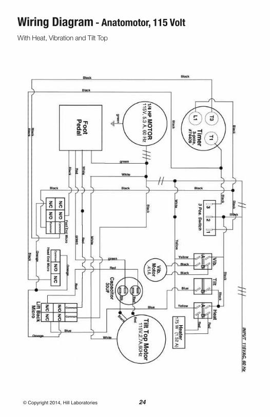
Wiring Diagram - Anatomotor, 115 VoltWith Heat, Vibration and Tilt Top
24© Copyright 2014, Hill Laboratories

Wiring Diagram - Anatomotor, 115 VoltWith Heat, Vibration, Tilt Top and Variable Speed
25© Copyright 2014, Hill Laboratories
26© Copyright 2014, Hill Laboratories
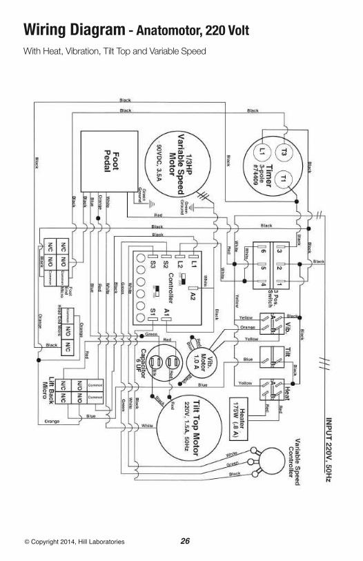
Wiring Diagram - Anatomotor, 220 VoltWith Heat, Vibration, Tilt Top and Variable Speed
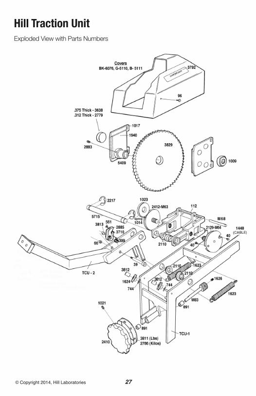
Hill Traction UnitExploded View with Parts Numbers
27© Copyright 2014, Hill Laboratories

AAdjusting on the Anatomotor 19
Ankle Harness 2, 12-14, 18, 20
Arm-Shoulder Traction 17
BBack Rollers 2, 6, 7, 9, 13, 16, 19, 22
Back Roller Handles 2, 5
Basic Function 4
CCervical-OFF-Lumbar Switch 4
Cervical-Lumbar Switch 4, 5, 9, 10, 16
Cervical Traction Device 2, 14, 21
Cleaning 3
Control Panel 2, 4
Counter Traction Bracket 2, 21
Counter Traction Unit 2, 19, 21
Cautions 3
EElectrical specifications 2
FFiller Block 4, 6, 7, 8, 13, 14, 19, 20, 21
Foot Pad 2, 7, 21
GGripper Bar 2, 17, 21
HHead Halter 2, 15, 16, 20
Heat 4, 19
LLeg Rollers 2, 7, 8, 21
Leg Roller Brackets 8, 9
Lumbar Traction 11-14
MMassage (See Roller Massage)
Maintenance 22
OOn/Off Switch See “Cervical-OFF-Lumbar Switch”
PParts Description 20
Passive Exercise 7, 8, 18, 20
Pillow 2, 8, 13, 14, 16, 20
RRoller Massage 6, 7- with Leg Rollers 7, 8
SService and Support See intro, “At Your Service”
Specifications 2
Speed Setting 10
Stationary Anatomotor 19
Stool 2, 10, 12
TTable Components 2
Thoracic Harness 11, 13, 20
Tilt-Top 4, 5, 24, 25
Timer 2, 4, 5
Top Pad 2, 4, 20
Traction / Traction Control Unit- Location of Traction Control Unit 2- How Traction Control Unit Works 9- Set Up and Use, Lumbar Traction 10-13- with Cervical Traction 14- with Head Halter 16- with Passive Exercise 18- Traction Unit Part Number 21- Traction Unit Exploded View 27
Traction Harness 2
Index
28© Copyright 2014, Hill Laboratories

29© Copyright 2014, Hill Laboratories
VVariable Speed 4, 6, 15, 25, 26
Vibration 2, 4, 5, 19, 24, 25
WWarranty See intro, “At Your Service”
Wiring diagrams 23-26
Index

3 N. Bacton Hill Road, Frazer, PA 19355 • www.HillLabs.com610-644-2867 • 1-877-445-5020 • Fax 610-647-6297