Embed Size (px)
Citation preview
CAUTION: Operation of combustion equip-ment can be hazardous resulting in bodily in-jury or equipment damage. Each burner shouldbe supervised by a combustion safeguard andonly quali�ed personnel should install, makesystem adjustments and perform any requiredservice.
NOTICE: PYRONICS practices apolicy of continuous improvement inthe design of its products. It reservesthe right to change the specifcationsat any time without prior notice.
HIJECTORS -- VENTURI MIXERSFOR HIGH PRESSURE GASES
MODEL: 2201-H, 2202-HC
Revision: 0 BULL
ETIN
2201
, 220
2
GENERAL DESCRIPTION
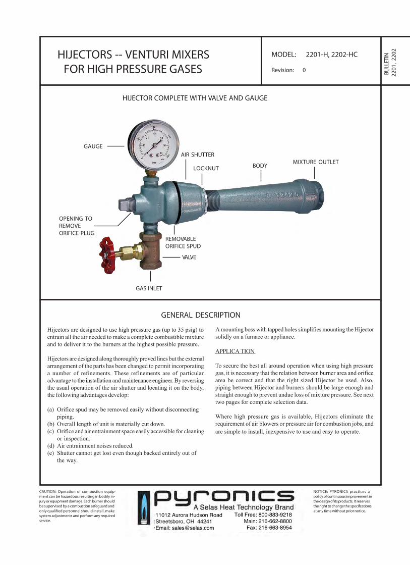
HIJECTOR COMPLETE WITH VALVE AND GAUGE
GAUGEAIR SHUTTER
LOCKNUT BODYMIXTURE OUTLET
VALVE
OPENING TOREMOVEORIFICE PLUG
REMOVABLEORIFICE SPUD
GAS INLET
Hijectors are designed to use high pressure gas (up to 35 psig) toentrain all the air needed to make a complete combustible mixtureand to deliver it to the burners at the highest possible pressure.
Hijectors are designed along thoroughly proved lines but the externalarrangement of the parts has been changed to permit incorporatinga number of refinements. These refinements are of particularadvantage to the installation and maintenance engineer. By reversingthe usual operation of the air shutter and locating it on the body,the following advantages develop:
(a) Orifice spud may be removed easily without disconnectingpiping.
(b) Overall length of unit is materially cut down.(c) Orifice and air entrainment space easily accessible for cleaning
or inspection.(d) Air entrainment noises reduced.(e) Shutter cannot get lost even though backed entirely out of
the way.
A mounting boss with tapped holes simplifies mounting the Hijectorsolidly on a furnace or appliance.
APPLICA TION
To secure the best all around operation when using high pressuregas, it is necessary that the relation between burner area and orificearea be correct and that the right sized Hijector be used. Also,piping between Hijector and burners should be large enough andstraight enough to prevent undue loss of mixture pressure. See nexttwo pages for complete selection data.
Where high pressure gas is available, Hijectors eliminate therequirement of air blowers or pressure air for combustion jobs, andare simple to install, inexpensive to use and easy to operate.
11012 Aurora Hudson RoadStreetsboro, OH 44241Email: [email protected]
Toll Free: 800-883-9218Main: 216-662-8800Fax: 216-663-8954
HIJECTORS -- VENTURI MIXERSFOR HIGH PRESSURE GASES
BULLETIN2201, 2202PAGE NO. 2
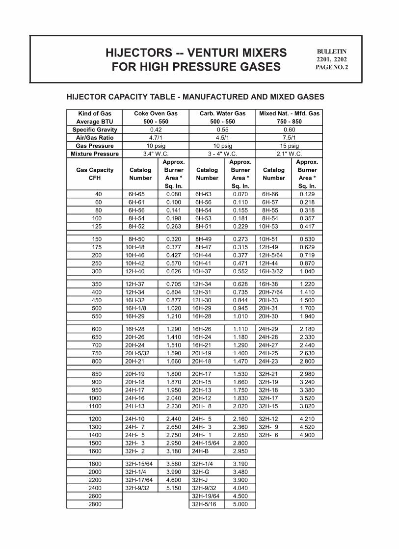
HIJECTOR CAPACITY TABLE - MANUFACTURED AND MIXED GASES
Kind of GasAverage BTU
Specific GravityAir/Gas RatioGas Pressure
Mixture PressureApprox. Approx. Approx.
Gas Capacity Catalog Burner Catalog Burner Catalog BurnerCFH Number Area * Number Area * Number Area *
Sq. In. Sq. In. Sq. In. 40 6H-65 0.080 6H-63 0.070 6H-66 0.129 60 6H-61 0.100 6H-56 0.110 6H-57 0.218 80 6H-56 0.141 6H-54 0.155 8H-55 0.318 100 8H-54 0.198 6H-53 0.181 8H-54 0.357 125 8H-52 0.263 8H-51 0.229 10H-53 0.417
150 8H-50 0.320 8H-49 0.273 10H-51 0.530 175 10H-48 0.377 8H-47 0.315 12H-49 0.629 200 10H-46 0.427 10H-44 0.377 12H-5/64 0.719 250 10H-42 0.570 10H-41 0.471 12H-44 0.870 300 12H-40 0.626 10H-37 0.552 16H-3/32 1.040
350 12H-37 0.705 12H-34 0.628 16H-38 1.220 400 12H-34 0.804 12H-31 0.735 20H-7/64 1.410 450 16H-32 0.877 12H-30 0.844 20H-33 1.500 500 16H-1/8 1.020 16H-29 0.945 20H-31 1.700 550 16H-29 1.210 16H-28 1.010 20H-30 1.940
600 16H-28 1.290 16H-26 1.110 24H-29 2.180 650 20H-26 1.410 16H-24 1.180 24H-28 2.330 700 20H-24 1.510 16H-21 1.290 24H-27 2.440 750 20H-5/32 1.590 20H-19 1.400 24H-25 2.630 800 20H-21 1.660 20H-18 1.470 24H-23 2.800
850 20H-19 1.800 20H-17 1.530 32H-21 2.980 900 20H-18 1.870 20H-15 1.660 32H-19 3.240 950 24H-17 1.950 20H-13 1.750 32H-18 3.380
1000 24H-16 2.040 20H-12 1.830 32H-17 3.520 1100 24H-13 2.230 20H- 8 2.020 32H-15 3.820
1200 24H-10 2.440 24H- 5 2.160 32H-12 4.210 1300 24H- 7 2.650 24H- 3 2.360 32H- 9 4.520 1400 24H- 5 2.750 24H- 1 2.650 32H- 6 4.900 1500 32H- 3 2.950 24H-15/64 2.800 1600 32H- 2 3.180 24H-B 2.950
1800 32H-15/64 3.580 32H-1/4 3.190 2000 32H-1/4 3.990 32H-G 3.480 2200 32H-17/64 4.600 32H-J 3.900 2400 32H-9/32 5.150 32H-9/32 4.040 2600 32H-19/64 4.500 2800 32H-5/16 5.000
10 psig3.4" W.C.
10 psig3 - 4" W.C.
Coke Oven Gas500 - 550
Carb. Water Gas500 - 550
0.554.5/1
0.424.7/1
15 psig2.1" W.C.
Mixed Nat. - Mfd. Gas750 - 850
0.607.5/1
CAUTION: Operation of combustion equip-ment can be hazardous resulting in bodily in-jury or equipment damage. Each burner shouldbe supervised by a combustion safeguard andonly quali�ed personnel should install, makesystem adjustments and perform any requiredservice.
NOTICE: PYRONICS practices apolicy of continuous improvement inthe design of its products. It reservesthe right to change the specifcationsat any time without prior notice.
HIJECTORS -- VENTURI MIXERSFOR HIGH PRESSURE GASES
BULLETIN2201, 2202PAGE NO. 3
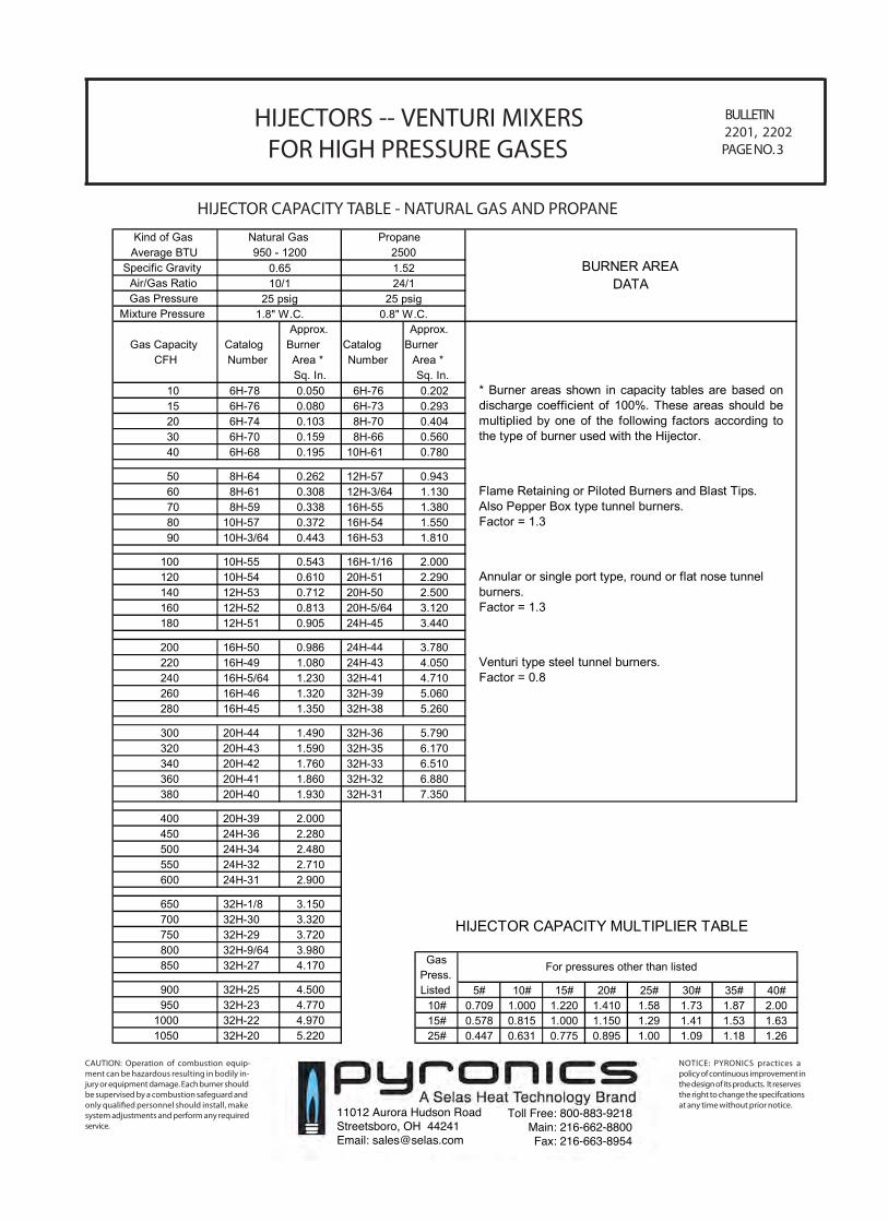
HIJECTOR CAPACITY TABLE - NATURAL GAS AND PROPANE
GasPress.Listed 5# 10# 15# 20# 25# 30# 35# 40#
10# 0.709 1.000 1.220 1.410 1.58 1.73 1.87 2.0015# 0.578 0.815 1.000 1.150 1.29 1.41 1.53 1.6325# 0.447 0.631 0.775 0.895 1.00 1.09 1.18 1.26
For pressures other than listed
Kind of GasAverage BTU
Specific GravityAir/Gas RatioGas Pressure
Mixture PressureApprox. Approx.
Gas Capacity Catalog Burner Catalog BurnerCFH Number Area * Number Area *
Sq. In. Sq. In. 10 6H-78 0.050 6H-76 0.202 15 6H-76 0.080 6H-73 0.293 20 6H-74 0.103 8H-70 0.404 30 6H-70 0.159 8H-66 0.560 40 6H-68 0.195 10H-61 0.780
50 8H-64 0.262 12H-57 0.943 60 8H-61 0.308 12H-3/64 1.130 70 8H-59 0.338 16H-55 1.380 80 10H-57 0.372 16H-54 1.550 90 10H-3/64 0.443 16H-53 1.810
100 10H-55 0.543 16H-1/16 2.000 120 10H-54 0.610 20H-51 2.290 140 12H-53 0.712 20H-50 2.500 160 12H-52 0.813 20H-5/64 3.120 180 12H-51 0.905 24H-45 3.440
200 16H-50 0.986 24H-44 3.780 220 16H-49 1.080 24H-43 4.050 240 16H-5/64 1.230 32H-41 4.710 260 16H-46 1.320 32H-39 5.060 280 16H-45 1.350 32H-38 5.260
300 20H-44 1.490 32H-36 5.790 320 20H-43 1.590 32H-35 6.170 340 20H-42 1.760 32H-33 6.510 360 20H-41 1.860 32H-32 6.880 380 20H-40 1.930 32H-31 7.350
400 20H-39 2.000 450 24H-36 2.280 500 24H-34 2.480 550 24H-32 2.710 600 24H-31 2.900
650 32H-1/8 3.150 700 32H-30 3.320 750 32H-29 3.720 800 32H-9/64 3.980 850 32H-27 4.170
900 32H-25 4.500 950 32H-23 4.770
1000 32H-22 4.970 1050 32H-20 5.220
Natural Gas Propane950 - 1200 2500
0.65 1.5210/1 24/1
25 psig 25 psig1.8" W.C. 0.8" W.C.
Annular or single port type, round or flat nose tunnel burners. Factor = 1.3
Venturi type steel tunnel burners. Factor = 0.8
BURNER AREADATA
HIJECTOR CAPACITY MULTIPLIER TABLE
* Burner areas shown in capacity tables are based ondischarge coefficient of 100%. These areas should bemultiplied by one of the following factors according tothe type of burner used with the Hijector.
Flame Retaining or Piloted Burners and Blast Tips. Also Pepper Box type tunnel burners. Factor = 1.3
11012 Aurora Hudson RoadStreetsboro, OH 44241Email: [email protected]
Toll Free: 800-883-9218Main: 216-662-8800Fax: 216-663-8954
ORDERING INFORMATION
HIJECTORS -- VENTURI MIXERSFOR HIGH PRESSURE GASES
BULLETIN2201, 2202PAGE NO. 4
Please include the following information for each size Hijector ordered:1. Number required.2. Catalog number complete, showing whether type H or HC and orifice size.3. Specify gauge range or maximum gas pressure used. 30GP is standard.4. List additional parts required by catalog number.5. Shipping Instructions.
If in doubt about Hijector selection, send complete information about burner, gasand application so we may assist you.
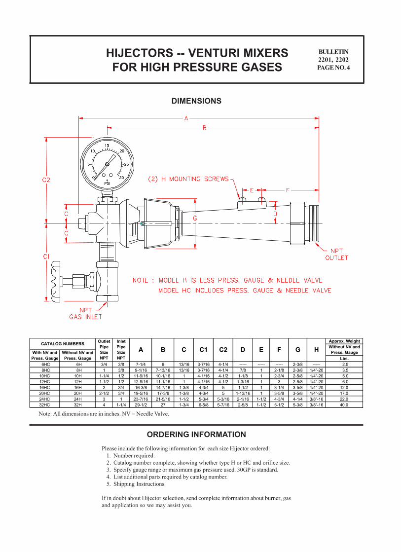
DIMENSIONS
Approx. Weight
Lbs. 6HC 6H 3/4 3/8 7-1/4 6 13/16 3-7/16 4-1/4 ----- ----- ----- 2-3/8 ----- 2.5 8HC 8H 1 3/8 9-1/16 7-13/16 13/16 3-7/16 4-1/4 7/8 1 2-1/8 2-3/8 1/4"-20 3.5 10HC 10H 1-1/4 1/2 11-9/16 10-1/16 1 4-1/16 4-1/2 1-1/8 1 2-3/4 2-5/8 1/4"-20 5.0 12HC 12H 1-1/2 1/2 12-9/16 11-1/16 1 4-1/16 4-1/2 1-3/16 1 3 2-5/8 1/4"-20 6.0 16HC 16H 2 3/4 16-3/8 14-7/16 1-3/8 4-3/4 5 1-1/2 1 3-1/4 3-5/8 1/4"-20 12.0 20HC 20H 2-1/2 3/4 19-5/16 17-3/8 1-3/8 4-3/4 5 1-13/16 1 3-5/8 3-5/8 1/4"-20 17.0 24HC 24H 3 1 23-7/16 21-5/16 1-1/2 5-3/4 5-3/16 2-1/16 1-1/2 4-3/4 4-1/4 3/8"-16 22.0 32HC 32H 4 1-1/4 29-1/2 27 1-3/4 6-5/8 5-7/16 2-5/8 1-1/2 5-1/2 5-3/8 3/8"-16 40.0
Without NV and Press. GaugeHC2With NV and
Press. GaugeWithout NV and Press. Gauge
CATALOG NUMBERSD E F GB C C1
Outlet Pipe Size NPT
Inlet Pipe Size NPT
A
Note: All dimensions are in inches. NV = Needle Valve.