Embed Size (px)
Citation preview
16HIGHWAY
ENGINEERING
Demetrios E. ToniasPresident
HMC Group Ltd.Saratoga Springs, New York
F or the purposes of this section, a high-way is considered a conduit that carriesvehicular traffic from one location toanother. Highway engineering deals
with provisions for meeting public needs for high-ways; environmental impact of highways; plan-ning, design, construction, maintenance, and reha-bilitation of highways; access to and exit fromhighways; economics and financing of highwayconstruction; traffic control; and safety of thoseusing or affected by the use of highways.
Highway engineering is continually evolving.While many of the design techniques employedare the same today as they were fifty or more yearsago, new concepts such as Intelligent VehicleHighway Systems (IVHS) and Pavement Manage-ment Systems (PMS) have significant effects onhighway engineering. This section presents thesenewer techniques as well as fundamental princi-ples of highway engineering and their practicalapplications based on long-time experience.
16.1 Classes of HighwaysHighways can range in character from a dirt roadin a rural setting to a multilane pavement in anurban environment. They are classified in accor-dance with functional characteristics. These char-
16.
Copyright (C) 1999 by The McGraw-Hill Cothis product is subject to the terms of its L
acteristics are based on the location of the road,such as urban or rural; width of the road, such assingle lane or multilane; and the type of service theroad is to provide, such as local access or travelbetween cities.
Principal guidelines for classifying highwaysare given in the American Association of StateHighway and Transportation Officials (AASHTO)guide, “A Policy on Geometric Design of Highwaysand Streets” (Policy). Highways are grouped inaccordance with the type of service they provide;that is, the type of travel associated with the road.Travel is facilitated by a highway network that iscomprised of various classes of highways. Figure16.1 presents a schematic of a highway networkcomposed of the three principal highway classes:arterials, collectors, and local roads.
Arterials are highways that provide direct ser-vice to major population centers. Collectors pro-vide direct service to towns and link up with arte-rials. Local roads connect various regions of amunicipality and tie into the system of collectors.Further subdivisions of these three principal cate-gories can be made by defining principal andminor arterials and major and minor collectors.
A principal arterial provides for main move-ment whereas a minor arterial acts as a distributor.Major and minor collectors are subclassifications
1
mpanies, Inc. All rights reserved. Use oficense Agreement. Click here to view.
16.2 n Section Sixteen
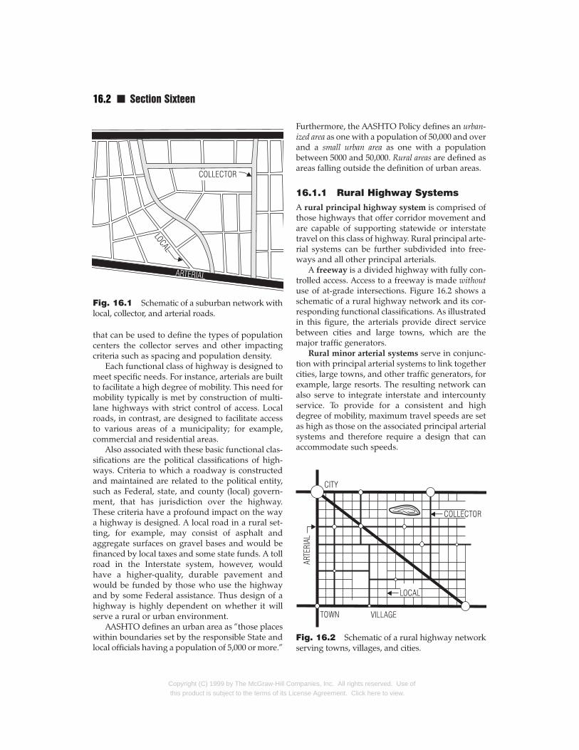
Fig. 16.1 Schematic of a suburban network withlocal, collector, and arterial roads.
that can be used to define the types of populationcenters the collector serves and other impactingcriteria such as spacing and population density.
Each functional class of highway is designed tomeet specific needs. For instance, arterials are builtto facilitate a high degree of mobility. This need formobility typically is met by construction of multi-lane highways with strict control of access. Localroads, in contrast, are designed to facilitate accessto various areas of a municipality; for example,commercial and residential areas.
Also associated with these basic functional clas-sifications are the political classifications of high-ways. Criteria to which a roadway is constructedand maintained are related to the political entity,such as Federal, state, and county (local) govern-ment, that has jurisdiction over the highway.These criteria have a profound impact on the waya highway is designed. A local road in a rural set-ting, for example, may consist of asphalt andaggregate surfaces on gravel bases and would befinanced by local taxes and some state funds. A tollroad in the Interstate system, however, wouldhave a higher-quality, durable pavement andwould be funded by those who use the highwayand by some Federal assistance. Thus design of ahighway is highly dependent on whether it willserve a rural or urban environment.
AASHTO defines an urban area as “those placeswithin boundaries set by the responsible State andlocal officials having a population of 5,000 or more.”
Copyright (C) 1999 by The McGraw-Hill Cothis product is subject to the terms of its Li
Furthermore, the AASHTO Policy defines an urban-ized area as one with a population of 50,000 and overand a small urban area as one with a populationbetween 5000 and 50,000. Rural areas are defined asareas falling outside the definition of urban areas.
16.1.1 Rural Highway SystemsA rural principal highway system is comprised ofthose highways that offer corridor movement andare capable of supporting statewide or interstatetravel on this class of highway. Rural principal arte-rial systems can be further subdivided into free-ways and all other principal arterials.
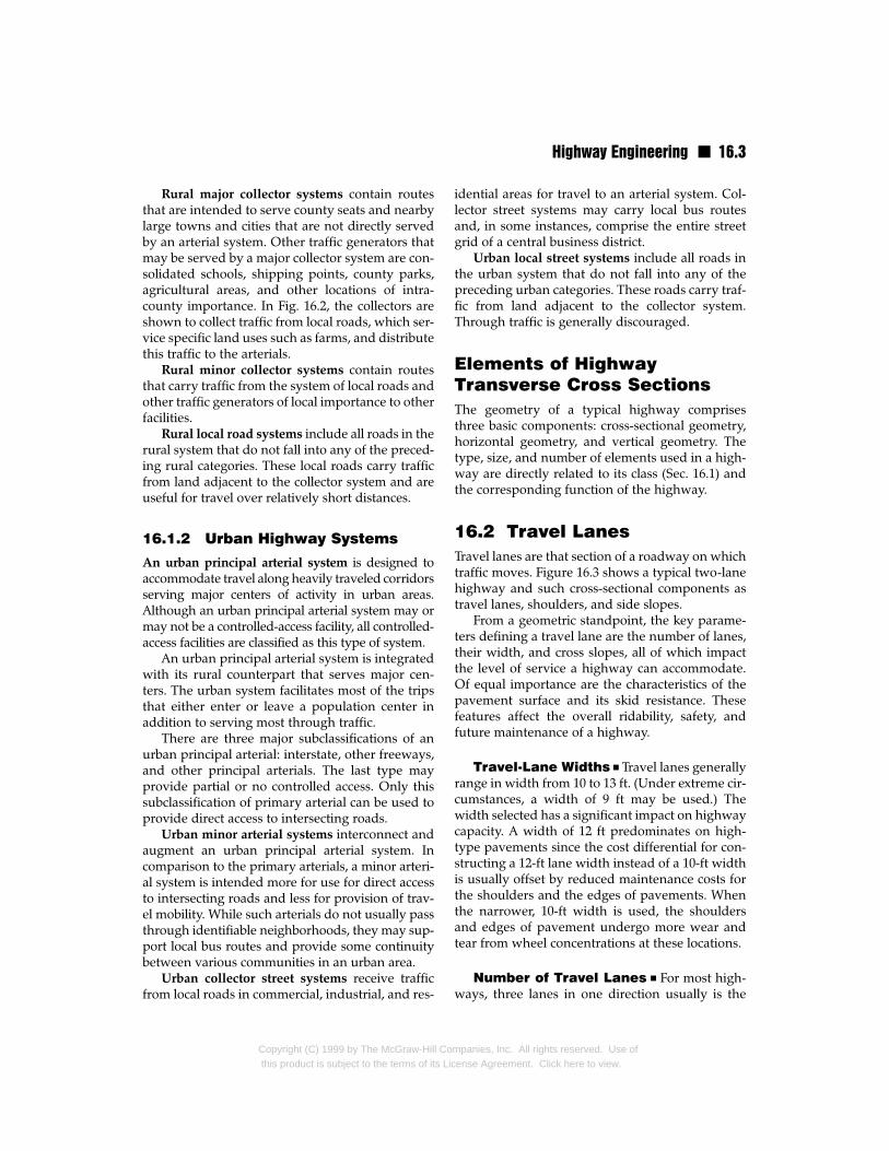
A freeway is a divided highway with fully con-trolled access. Access to a freeway is made withoutuse of at-grade intersections. Figure 16.2 shows aschematic of a rural highway network and its cor-responding functional classifications. As illustratedin this figure, the arterials provide direct servicebetween cities and large towns, which are themajor traffic generators.
Rural minor arterial systems serve in conjunc-tion with principal arterial systems to link togethercities, large towns, and other traffic generators, forexample, large resorts. The resulting network canalso serve to integrate interstate and intercountyservice. To provide for a consistent and highdegree of mobility, maximum travel speeds are setas high as those on the associated principal arterialsystems and therefore require a design that canaccommodate such speeds.
Fig. 16.2 Schematic of a rural highway networkserving towns, villages, and cities.
mpanies, Inc. All rights reserved. Use ofcense Agreement. Click here to view.
Highway Engineering n 16.3
Rural major collector systems contain routesthat are intended to serve county seats and nearbylarge towns and cities that are not directly servedby an arterial system. Other traffic generators thatmay be served by a major collector system are con-solidated schools, shipping points, county parks,agricultural areas, and other locations of intra-county importance. In Fig. 16.2, the collectors areshown to collect traffic from local roads, which ser-vice specific land uses such as farms, and distributethis traffic to the arterials.
Rural minor collector systems contain routesthat carry traffic from the system of local roads andother traffic generators of local importance to otherfacilities.
Rural local road systems include all roads in therural system that do not fall into any of the preced-ing rural categories. These local roads carry trafficfrom land adjacent to the collector system and areuseful for travel over relatively short distances.
16.1.2 Urban Highway Systems
An urban principal arterial system is designed toaccommodate travel along heavily traveled corridorsserving major centers of activity in urban areas.Although an urban principal arterial system may ormay not be a controlled-access facility, all controlled-access facilities are classified as this type of system.
An urban principal arterial system is integratedwith its rural counterpart that serves major cen-ters. The urban system facilitates most of the tripsthat either enter or leave a population center inaddition to serving most through traffic.
There are three major subclassifications of anurban principal arterial: interstate, other freeways,and other principal arterials. The last type mayprovide partial or no controlled access. Only thissubclassification of primary arterial can be used toprovide direct access to intersecting roads.
Urban minor arterial systems interconnect andaugment an urban principal arterial system. Incomparison to the primary arterials, a minor arteri-al system is intended more for use for direct accessto intersecting roads and less for provision of trav-el mobility. While such arterials do not usually passthrough identifiable neighborhoods, they may sup-port local bus routes and provide some continuitybetween various communities in an urban area.
Urban collector street systems receive trafficfrom local roads in commercial, industrial, and res-
Copyright (C) 1999 by The McGraw-Hill Cothis product is subject to the terms of its Li
idential areas for travel to an arterial system. Col-lector street systems may carry local bus routesand, in some instances, comprise the entire streetgrid of a central business district.
Urban local street systems include all roads inthe urban system that do not fall into any of thepreceding urban categories. These roads carry traf-fic from land adjacent to the collector system.Through traffic is generally discouraged.
Elements of HighwayTransverse Cross SectionsThe geometry of a typical highway comprisesthree basic components: cross-sectional geometry,horizontal geometry, and vertical geometry. Thetype, size, and number of elements used in a high-way are directly related to its class (Sec. 16.1) andthe corresponding function of the highway.
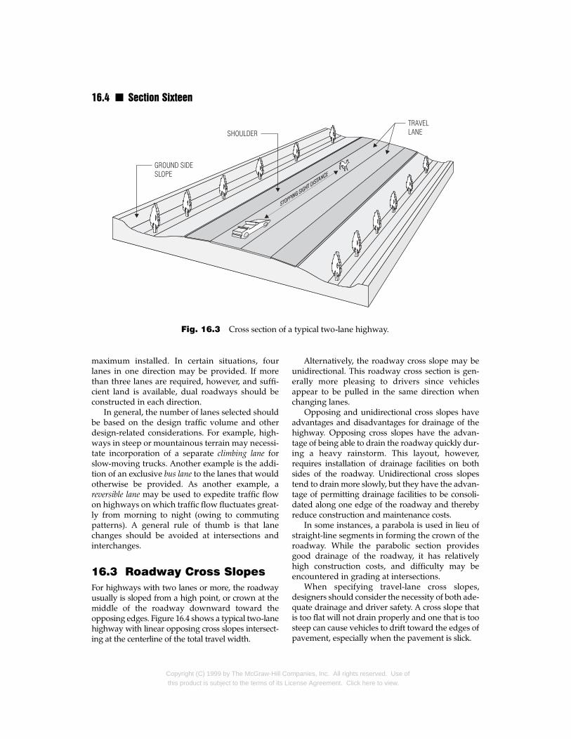
16.2 Travel LanesTravel lanes are that section of a roadway on whichtraffic moves. Figure 16.3 shows a typical two-lanehighway and such cross-sectional components astravel lanes, shoulders, and side slopes.
From a geometric standpoint, the key parame-ters defining a travel lane are the number of lanes,their width, and cross slopes, all of which impactthe level of service a highway can accommodate.Of equal importance are the characteristics of thepavement surface and its skid resistance. Thesefeatures affect the overall ridability, safety, andfuture maintenance of a highway.
Travel-Lane Widths n Travel lanes generallyrange in width from 10 to 13 ft. (Under extreme cir-cumstances, a width of 9 ft may be used.) Thewidth selected has a significant impact on highwaycapacity. A width of 12 ft predominates on high-type pavements since the cost differential for con-structing a 12-ft lane width instead of a 10-ft widthis usually offset by reduced maintenance costs forthe shoulders and the edges of pavements. Whenthe narrower, 10-ft width is used, the shouldersand edges of pavement undergo more wear andtear from wheel concentrations at these locations.
Number of Travel Lanes n For most high-ways, three lanes in one direction usually is the
mpanies, Inc. All rights reserved. Use ofcense Agreement. Click here to view.
16.4 n Section Sixteen
Fig. 16.3 Cross section of a typical two-lane highway.
maximum installed. In certain situations, fourlanes in one direction may be provided. If morethan three lanes are required, however, and suffi-cient land is available, dual roadways should beconstructed in each direction.
In general, the number of lanes selected shouldbe based on the design traffic volume and otherdesign-related considerations. For example, high-ways in steep or mountainous terrain may necessi-tate incorporation of a separate climbing lane forslow-moving trucks. Another example is the addi-tion of an exclusive bus lane to the lanes that wouldotherwise be provided. As another example, areversible lane may be used to expedite traffic flowon highways on which traffic flow fluctuates great-ly from morning to night (owing to commutingpatterns). A general rule of thumb is that lanechanges should be avoided at intersections andinterchanges.
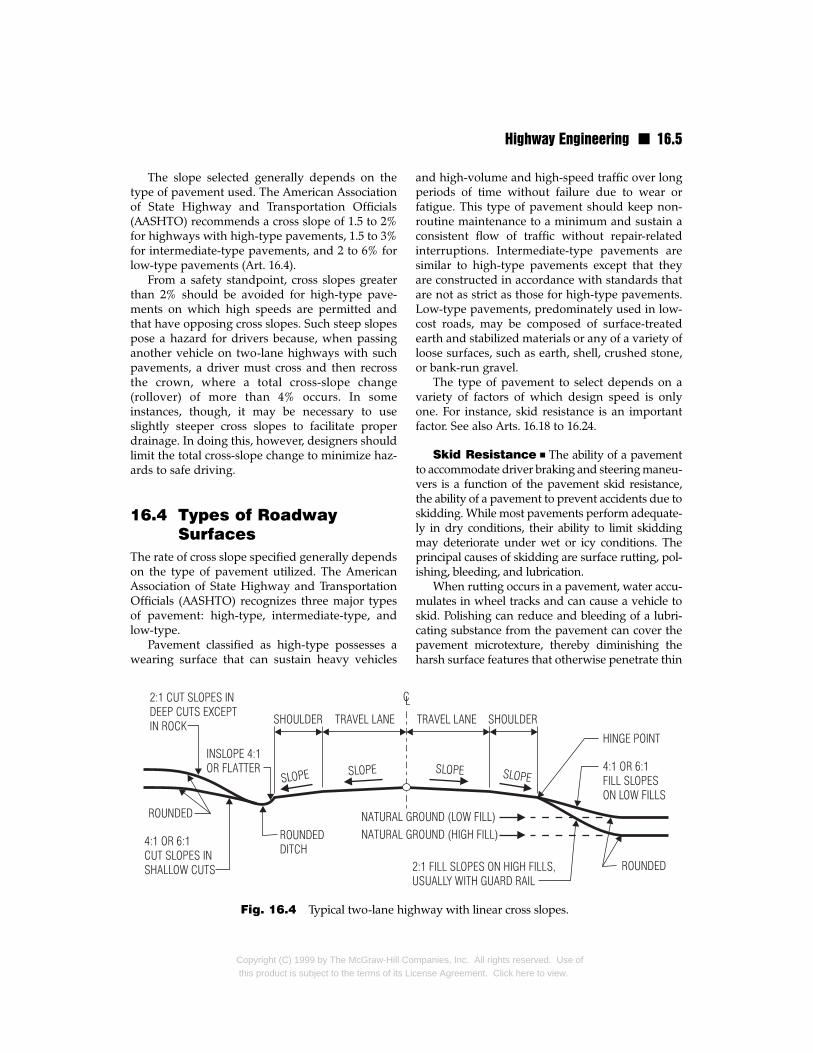
16.3 Roadway Cross SlopesFor highways with two lanes or more, the roadwayusually is sloped from a high point, or crown at themiddle of the roadway downward toward theopposing edges. Figure 16.4 shows a typical two-lanehighway with linear opposing cross slopes intersect-ing at the centerline of the total travel width.
Copyright (C) 1999 by The McGraw-Hill Cothis product is subject to the terms of its Lic
Alternatively, the roadway cross slope may beunidirectional. This roadway cross section is gen-erally more pleasing to drivers since vehiclesappear to be pulled in the same direction whenchanging lanes.
Opposing and unidirectional cross slopes haveadvantages and disadvantages for drainage of thehighway. Opposing cross slopes have the advan-tage of being able to drain the roadway quickly dur-ing a heavy rainstorm. This layout, however,requires installation of drainage facilities on bothsides of the roadway. Unidirectional cross slopestend to drain more slowly, but they have the advan-tage of permitting drainage facilities to be consoli-dated along one edge of the roadway and therebyreduce construction and maintenance costs.
In some instances, a parabola is used in lieu ofstraight-line segments in forming the crown of theroadway. While the parabolic section providesgood drainage of the roadway, it has relativelyhigh construction costs, and difficulty may beencountered in grading at intersections.
When specifying travel-lane cross slopes,designers should consider the necessity of both ade-quate drainage and driver safety. A cross slope thatis too flat will not drain properly and one that is toosteep can cause vehicles to drift toward the edges ofpavement, especially when the pavement is slick.
mpanies, Inc. All rights reserved. Use ofense Agreement. Click here to view.
Highway Engineering n 16.5
The slope selected generally depends on thetype of pavement used. The American Associationof State Highway and Transportation Officials(AASHTO) recommends a cross slope of 1.5 to 2%for highways with high-type pavements, 1.5 to 3%for intermediate-type pavements, and 2 to 6% forlow-type pavements (Art. 16.4).
From a safety standpoint, cross slopes greaterthan 2% should be avoided for high-type pave-ments on which high speeds are permitted andthat have opposing cross slopes. Such steep slopespose a hazard for drivers because, when passinganother vehicle on two-lane highways with suchpavements, a driver must cross and then recrossthe crown, where a total cross-slope change(rollover) of more than 4% occurs. In someinstances, though, it may be necessary to useslightly steeper cross slopes to facilitate properdrainage. In doing this, however, designers shouldlimit the total cross-slope change to minimize haz-ards to safe driving.
16.4 Types of RoadwaySurfaces
The rate of cross slope specified generally dependson the type of pavement utilized. The AmericanAssociation of State Highway and TransportationOfficials (AASHTO) recognizes three major typesof pavement: high-type, intermediate-type, andlow-type.
Pavement classified as high-type possesses awearing surface that can sustain heavy vehicles
Fig. 16.4 Typical two-lane high
Copyright (C) 1999 by The McGraw-Hill Cothis product is subject to the terms of its Lic
and high-volume and high-speed traffic over longperiods of time without failure due to wear orfatigue. This type of pavement should keep non-routine maintenance to a minimum and sustain aconsistent flow of traffic without repair-relatedinterruptions. Intermediate-type pavements aresimilar to high-type pavements except that theyare constructed in accordance with standards thatare not as strict as those for high-type pavements.Low-type pavements, predominately used in low-cost roads, may be composed of surface-treatedearth and stabilized materials or any of a variety ofloose surfaces, such as earth, shell, crushed stone,or bank-run gravel.
The type of pavement to select depends on avariety of factors of which design speed is onlyone. For instance, skid resistance is an importantfactor. See also Arts. 16.18 to 16.24.
Skid Resistance n The ability of a pavementto accommodate driver braking and steering maneu-vers is a function of the pavement skid resistance,the ability of a pavement to prevent accidents due toskidding. While most pavements perform adequate-ly in dry conditions, their ability to limit skiddingmay deteriorate under wet or icy conditions. Theprincipal causes of skidding are surface rutting, pol-ishing, bleeding, and lubrication.
When rutting occurs in a pavement, water accu-mulates in wheel tracks and can cause a vehicle toskid. Polishing can reduce and bleeding of a lubri-cating substance from the pavement can cover thepavement microtexture, thereby diminishing theharsh surface features that otherwise penetrate thin
way with linear cross slopes.
mpanies, Inc. All rights reserved. Use ofense Agreement. Click here to view.
16.6 n Section Sixteen
water film and offer skid resistance. Lubrication of apavement surface with dust, organic matter, oil,moisture, ice, sand, or other deposits can cause areduction in or complete loss of skid resistance.
16.5 ShouldersA shoulder (also known as a verge) is that part of aroadway between the edge of the traveled wayand the edge of an adjacent curb, ground sideslope, or drainage feature, such as a ditch or gutter(Fig. 16.5). A shoulder is designed to accommodatestopping and temporary parking of vehicles, emer-gency use, and lateral support of base and surfacecourses. Shoulders should be capable of sustainingstarting, stopping, and movement of vehicles with-out appreciable rutting.
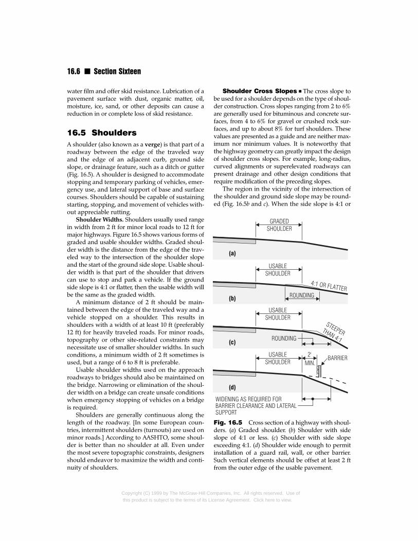
Shoulder Widths. Shoulders usually used rangein width from 2 ft for minor local roads to 12 ft formajor highways. Figure 16.5 shows various forms ofgraded and usable shoulder widths. Graded shoul-der width is the distance from the edge of the trav-eled way to the intersection of the shoulder slopeand the start of the ground side slope. Usable shoul-der width is that part of the shoulder that driverscan use to stop and park a vehicle. If the groundside slope is 4:1 or flatter, then the usable width willbe the same as the graded width.
A minimum distance of 2 ft should be main-tained between the edge of the traveled way and avehicle stopped on a shoulder. This results inshoulders with a width of at least 10 ft (preferably12 ft) for heavily traveled roads. For minor roads,topography or other site-related constraints maynecessitate use of smaller shoulder widths. In suchconditions, a minimum width of 2 ft sometimes isused, but a range of 6 to 8 ft is preferable.
Usable shoulder widths used on the approachroadways to bridges should also be maintained onthe bridge. Narrowing or elimination of the shoul-der width on a bridge can create unsafe conditionswhen emergency stopping of vehicles on a bridgeis required.
Shoulders are generally continuous along thelength of the roadway. [In some European coun-tries, intermittent shoulders (turnouts) are used onminor roads.] According to AASHTO, some shoul-der is better than no shoulder at all. Even underthe most severe topographic constraints, designersshould endeavor to maximize the width and conti-nuity of shoulders.
Copyright (C) 1999 by The McGraw-Hill Cothis product is subject to the terms of its Lic
Shoulder Cross Slopes n The cross slope tobe used for a shoulder depends on the type of shoul-der construction. Cross slopes ranging from 2 to 6%are generally used for bituminous and concrete sur-faces, from 4 to 6% for gravel or crushed rock sur-faces, and up to about 8% for turf shoulders. Thesevalues are presented as a guide and are neither max-imum nor minimum values. It is noteworthy thatthe highway geometry can greatly impact the designof shoulder cross slopes. For example, long-radius,curved alignments or superelevated roadways canpresent drainage and other design conditions thatrequire modification of the preceding slopes.
The region in the vicinity of the intersection ofthe shoulder and ground side slope may be round-ed (Fig. 16.5b and c). When the side slope is 4:1 or
Fig. 16.5 Cross section of a highway with shoul-ders. (a) Graded shoulder. (b) Shoulder with sideslope of 4:1 or less. (c) Shoulder with side slopeexceeding 4:1. (d) Shoulder wide enough to permitinstallation of a guard rail, wall, or other barrier.Such vertical elements should be offset at least 2 ftfrom the outer edge of the usable pavement.
mpanies, Inc. All rights reserved. Use ofense Agreement. Click here to view.
Highway Engineering n 16.7
flatter, the rounding may be 4 to 6 ft wide withoutadverse impact on the usable shoulder width.
If a barrier is installed outside a shoulder, thereshould be at least 2-ft clearance between the barri-er and the usable shoulder, which should bewidened as needed for barrier clearance and later-al support (Fig. 16.5d). If curbs are placed on theouter side of shoulders, the design should ensuregood drainage to prevent excessive ponding. Inextreme conditions, ponding can encroach into thetraveled way and hinder traffic or cause accidents.
Shoulder Stability n Shoulders should bedesigned not only to support vehicle loading with-out appreciable rutting but also to be contiguouswith the traveled way. They must be constructedflush with the paved surface of the traveled way ifthey are to function properly. In addition, shoul-ders should be stabilized so that they remain flushin service.
Shoulders that are not properly stabilized cansettle enough to adversely affect a driver’s controlof a vehicle moving from the traveled way to theshoulder. This situation can also encourage driversto avoid the pavement edge adjoining the shoul-der intentionally, thereby increasing the chance ofaccidents.
Shoulder-Pavement Contrast n It is desir-able to vary the color and texture of a shoulderfrom that of the travel lanes. The resulting contrastserves the dual function of providing clear differ-entiation between travel lanes and shoulders anddiscouraging the use of shoulders as throughlanes.
Bituminous, gravel, crushed rock, and turfshoulders offer excellent contrast with concretelanes. For bituminous lanes, one method ofenhancing contrast between the travel lanes andshoulders is to seal-coat the shoulders with lighter-color stone chips. A drawback to this method isthat contrast may diminish with time. Additionalcontrast can be provided by installation of reflec-tive striping at the edge of the traveled way.
16.6 CurbsA curb is a raised element that is used, among otherthings, to denote the edge of a roadway. Curbs canbe made of portland cement or bituminous con-crete, granite, or some other hard material. In addi-
Copyright (C) 1999 by The McGraw-Hill Cothis product is subject to the terms of its Li
tion to pavement delineation, curbs providedrainage control, right-of-way reduction, enhancedappearance, delineation of pedestrian walkways,and reduction of maintenance operations. To facili-tate drainage, curbs can be combined with a gutterto create a combined curb-gutter section.
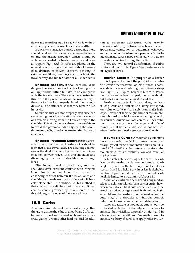
There are two general classifications of curbs:barrier and mountable. Figure 16.6 illustrates vari-ous types of curbs.
Barrier Curbs n The purpose of a barriercurb is to prevent or limit the possibility of a vehi-cle’s leaving the roadway. For this purpose, a barri-er curb is made relatively high and given a steepface (Fig. 16.6a). Typical height is 6 to 9 in. Whenthe roadway-side face is sloped, the batter shouldnot exceed 1 in horizontal on 3 in vertical.
Barrier curbs are typically used along the facesof long walls and tunnels and along low-speed,low-volume roadways but rarely along major high-ways. Because of their height, these curbs can pre-sent a hazard to vehicles traveling at high speeds,inasmuch as drivers can lose control of their vehi-cles on contacting the curbs A general rule ofthumb is that barrier curbs should not be usedwhen the design speed is greater than 40 mi/h.
Mountable Curbs n A mountable curb offersthe advantage that a vehicle can cross it when nec-essary. Typical forms of mountable curbs are illus-trated in Fig.16.6b to g. In contrast to barrier curbs,mountable curbs are relatively low and have flatsloping faces.
To facilitate vehicle crossing of the curbs, the curbfaces on the roadway side may be rounded. Curbheight depends on the face slope. For face slopessteeper than 1:1, a height of 4 in or less is desirable.For face slopes that fall between 1:1 and 2:1, curbheight is limited to a maximum of about 6 in.
Mountable curbs may be installed along medianedges to delineate islands. Like barrier curbs, how-ever, mountable curbs should not be used along thetravel-way edges of high-speed, high-volume high-ways. Mountable curbs are often used along theouter edge of a shoulder for drainage control,reduction of erosion, and enhanced delineation.
Color and texture of mountable curbs should becontrasted with that of the adjacent roadway toenhance their visibility, especially at night and inadverse weather conditions. One method used toenhance visibility of curbs is to apply reflective sur-
mpanies, Inc. All rights reserved. Use ofcense Agreement. Click here to view.
16.8 n Section Sixteen
faces. Another approach is to form on the curbsdepressions and ribs that reflect headlight beams.
16.7 SidewalksSidewalks are used predominately in urban envi-ronments, but they are also used in rural areas thatare adjacent to schools or other regions, such asshopping centers, where pedestrian traffic is highand sidewalks can help minimize pedestrian-relat-ed accidents. Because of their expense, use of side-walks must be warranted before they are incorpo-
Fig. 16.6 Typical highway curbs. (a) Barrier curb useto (g) Mountable curbs that permit vehicles to cross whe
Copyright (C) 1999 by The McGraw-Hill Comthis product is subject to the terms of its Lic
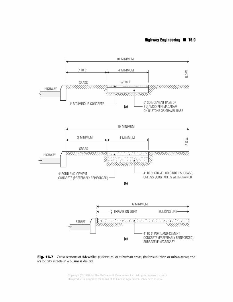
rated in a highway cross section. A shoulder cansometimes fulfill the role of a sidewalk if it is con-structed and maintained in a way that encouragespedestrian use. Sidewalks, when installed, howev-er, should always be separated from a shoulder,preferably by a curb (Fig. 16.7).
Typical width of sidewalks is 4 to 8 ft. For areaswith a large amount of pedestrian traffic, a side-walk should be at least 6 ft wide.
Sidewalks should be constructed of weather-resistant materials. They should be maintainedfree from debris and vegetation growth. When
d to prevent vehicles from leaving the roadway. (b)n necessary. Slopes of curb faces and rounding vary.
panies, Inc. All rights reserved. Use ofense Agreement. Click here to view.
Highway Engineering n 16.9
Fig. 16.7 Cross sections of sidewalks: (a) for rural or suburban areas; (b) for suburban or urban areas; and(c) for city streets in a business district.
Copyright (C) 1999 by The McGraw-Hill Companies, Inc. All rights reserved. Use ofthis product is subject to the terms of its License Agreement. Click here to view.
16.10 n Section Sixteen
allowed to deteriorate because of poor mainte-nance, sidewalks will go unused because pedes-trians will choose to walk on the travel lanesrather than the sidewalks. Not only does thisdefeat the intended function of the sidewalks(and justification for the additional expense) butit also greatly increases the risk of pedestrian-related accidents.
16.8 Traffic BarriersRoadside barriers are used to protect vehicles andtheir occupants from impact with natural or man-made features at the side of the road. In addition toprotecting vehicles, traffic barriers can also be usedto shield pedestrians, construction crews, orcyclists from errant traffic. In its most basic form, atraffic barrier is designed to prevent a vehicle leav-ing the traveled way from striking a fixed object.The barrier must first contain an errant vehicle andthen redirect it. Because of the variable nature ofvehicle impacts and the destructive effects at highspeeds, extensive full-scale crash tests should beconducted to ensure the adequacy of the trafficbarrier to be used.
Barriers are available in a large variety of sizesand shapes. Choice of type of barrier to usedepends on a variety of factors, including the envi-ronment in which the highway is located and thespeed and volume of traffic.
Traffic barriers may be classified as longitudinalbarriers, bridge railings and barriers, and crashcushions.
16.8.1 Longitudinal Barriers
Longitudinal barriers can be classified as roadsidebarriers and median barriers. Whereas a roadsidebarrier may be placed on either side of a roadway,a median barrier is placed between lanes of traffictraveling in opposite directions.
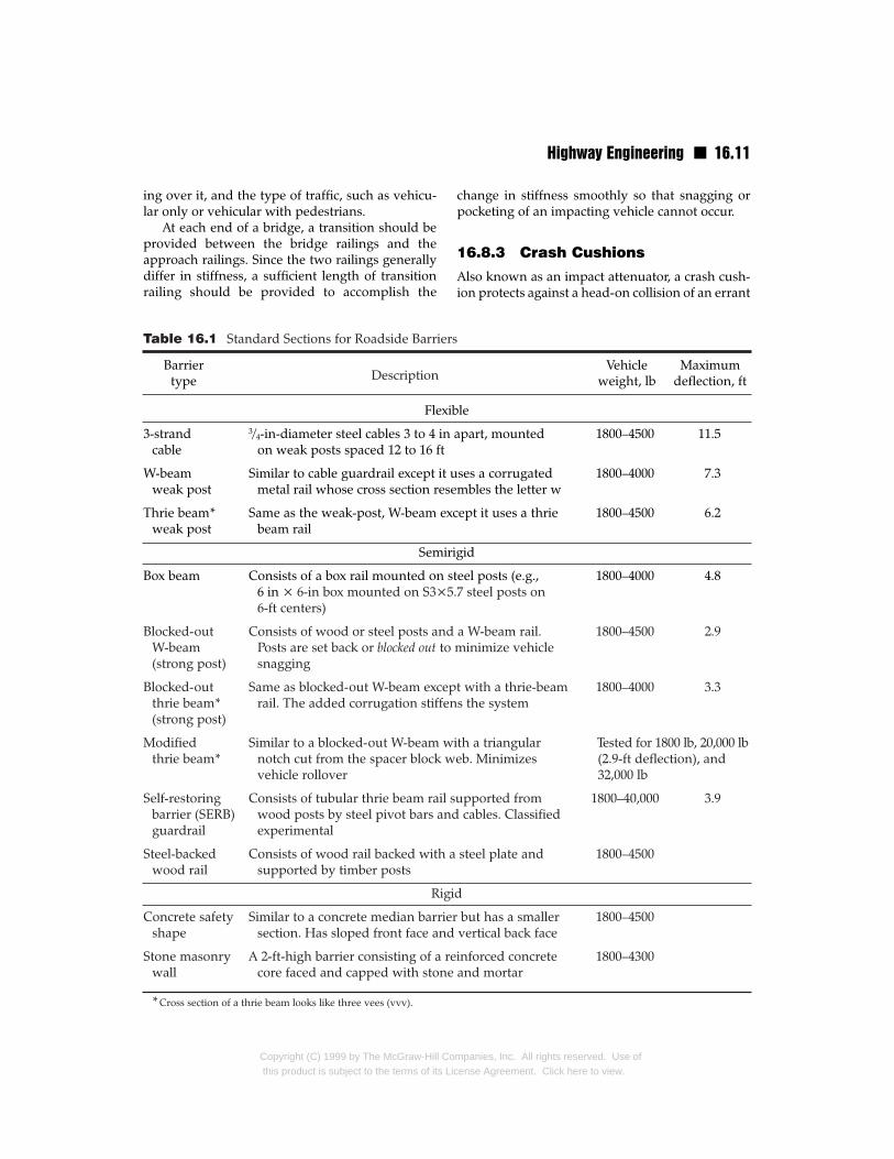
Barriers differ in the amount of deflection theyundergo when struck by a vehicle. The principalcategories of longitudinal barriers, based on theamount of deflection allowed, are flexible, semi-rigid, and rigid systems. Table 16.1 presents somebasic forms of roadside barriers as given in the“Roadside Design Guide,” American Association ofState Highway and Transportation Officials(AASHTO), which discusses selection and imple-mentation of traffic barrier systems.
Copyright (C) 1999 by The McGraw-Hill Cothis product is subject to the terms of its Lic
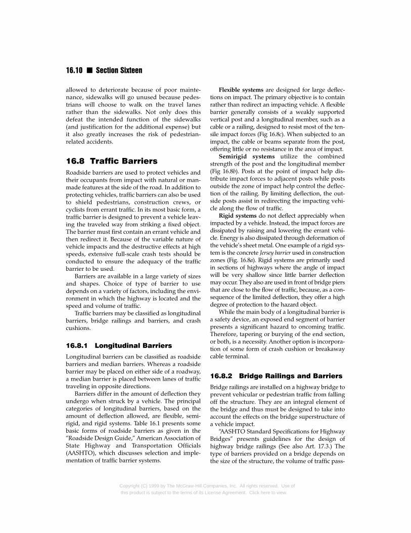
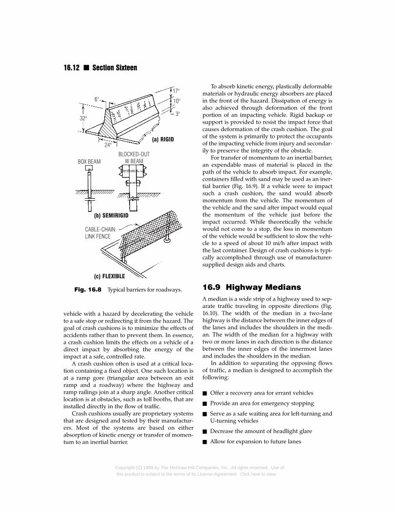
Flexible systems are designed for large deflec-tions on impact. The primary objective is to containrather than redirect an impacting vehicle. A flexiblebarrier generally consists of a weakly supportedvertical post and a longitudinal member, such as acable or a railing, designed to resist most of the ten-sile impact forces (Fig 16.8c). When subjected to animpact, the cable or beams separate from the post,offering little or no resistance in the area of impact.
Semirigid systems utilize the combinedstrength of the post and the longitudinal member(Fig 16.8b). Posts at the point of impact help dis-tribute impact forces to adjacent posts while postsoutside the zone of impact help control the deflec-tion of the railing. By limiting deflection, the out-side posts assist in redirecting the impacting vehi-cle along the flow of traffic.
Rigid systems do not deflect appreciably whenimpacted by a vehicle. Instead, the impact forces aredissipated by raising and lowering the errant vehi-cle. Energy is also dissipated through deformation ofthe vehicle’s sheet metal. One example of a rigid sys-tem is the concrete Jersey barrier used in constructionzones (Fig. 16.8a). Rigid systems are primarily usedin sections of highways where the angle of impactwill be very shallow since little barrier deflectionmay occur. They also are used in front of bridge piersthat are close to the flow of traffic, because, as a con-sequence of the limited deflection, they offer a highdegree of protection to the hazard object.
While the main body of a longitudinal barrier isa safety device, an exposed end segment of barrierpresents a significant hazard to oncoming traffic.Therefore, tapering or burying of the end section,or both, is a necessity. Another option is incorpora-tion of some form of crash cushion or breakawaycable terminal.
16.8.2 Bridge Railings and Barriers
Bridge railings are installed on a highway bridge toprevent vehicular or pedestrian traffic from fallingoff the structure. They are an integral element ofthe bridge and thus must be designed to take intoaccount the effects on the bridge superstructure ofa vehicle impact.
“AASHTO Standard Specifications for HighwayBridges” presents guidelines for the design ofhighway bridge railings (See also Art. 17.3.) Thetype of barriers provided on a bridge depends onthe size of the structure, the volume of traffic pass-
mpanies, Inc. All rights reserved. Use ofense Agreement. Click here to view.
Highway Engineering n 16.11
ing over it, and the type of traffic, such as vehicu-lar only or vehicular with pedestrians.
At each end of a bridge, a transition should beprovided between the bridge railings and theapproach railings. Since the two railings generallydiffer in stiffness, a sufficient length of transitionrailing should be provided to accomplish the
Barriertype
Flexib
3-strand 3/4-in-diameter steel cables 3 to 4 in cable on weak posts spaced 12 to 16 ft
W-beam Similar to cable guardrail except it uweak post metal rail whose cross section rese
Thrie beam* Same as the weak-post, W-beam exweak post beam rail
Semir
Box beam Consists of a box rail mounted on s6 in × 6-in box mounted on S3×56-ft centers)
Blocked-out Consists of wood or steel posts andW-beam Posts are set back or blocked out to (strong post) snagging
Blocked-out Same as blocked-out W-beam excepthrie beam* rail. The added corrugation stiffen(strong post)
Modified Similar to a blocked-out W-beam wthrie beam* notch cut from the spacer block w
vehicle rollover
Self-restoring Consists of tubular thrie beam rail sbarrier (SERB) wood posts by steel pivot bars andguardrail experimental
Steel-backed Consists of wood rail backed with awood rail supported by timber posts
Rigi
Concrete safety Similar to a concrete median barrieshape section. Has sloped front face and
Stone masonry A 2-ft-high barrier consisting of a rewall core faced and capped with stone
*Cross section of a thrie beam looks like three vees (vvv).
Table 16.1 Standard Sections for Roadside Barrier
Description
Copyright (C) 1999 by The McGraw-Hill Cothis product is subject to the terms of its Li
change in stiffness smoothly so that snagging orpocketing of an impacting vehicle cannot occur.
16.8.3 Crash Cushions
Also known as an impact attenuator, a crash cush-ion protects against a head-on collision of an errant
Vehicle Maximumweight, lb deflection, ft
le
apart, mounted 1800–4500 11.5
ses a corrugated 1800–4000 7.3mbles the letter w
cept it uses a thrie 1800–4500 6.2
igid
teel posts (e.g., 1800–4000 4.8.7 steel posts on
a W-beam rail. 1800–4500 2.9minimize vehicle
t with a thrie-beam 1800–4000 3.3s the system
ith a triangular Tested for 1800 lb, 20,000 lbeb. Minimizes (2.9-ft deflection), and
32,000 lb
upported from 1800–40,000 3.9 cables. Classified
steel plate and 1800–4500
d
r but has a smaller 1800–4500 vertical back face
inforced concrete 1800–4300 and mortar
s
mpanies, Inc. All rights reserved. Use ofcense Agreement. Click here to view.
16.12 n Section Sixteen
vehicle with a hazard by decelerating the vehicleto a safe stop or redirecting it from the hazard. Thegoal of crash cushions is to minimize the effects ofaccidents rather than to prevent them. In essence,a crash cushion limits the effects on a vehicle of adirect impact by absorbing the energy of theimpact at a safe, controlled rate.
A crash cushion often is used at a critical loca-tion containing a fixed object. One such location isat a ramp gore (triangular area between an exitramp and a roadway) where the highway andramp railings join at a sharp angle. Another criticallocation is at obstacles, such as toll booths, that areinstalled directly in the flow of traffic.
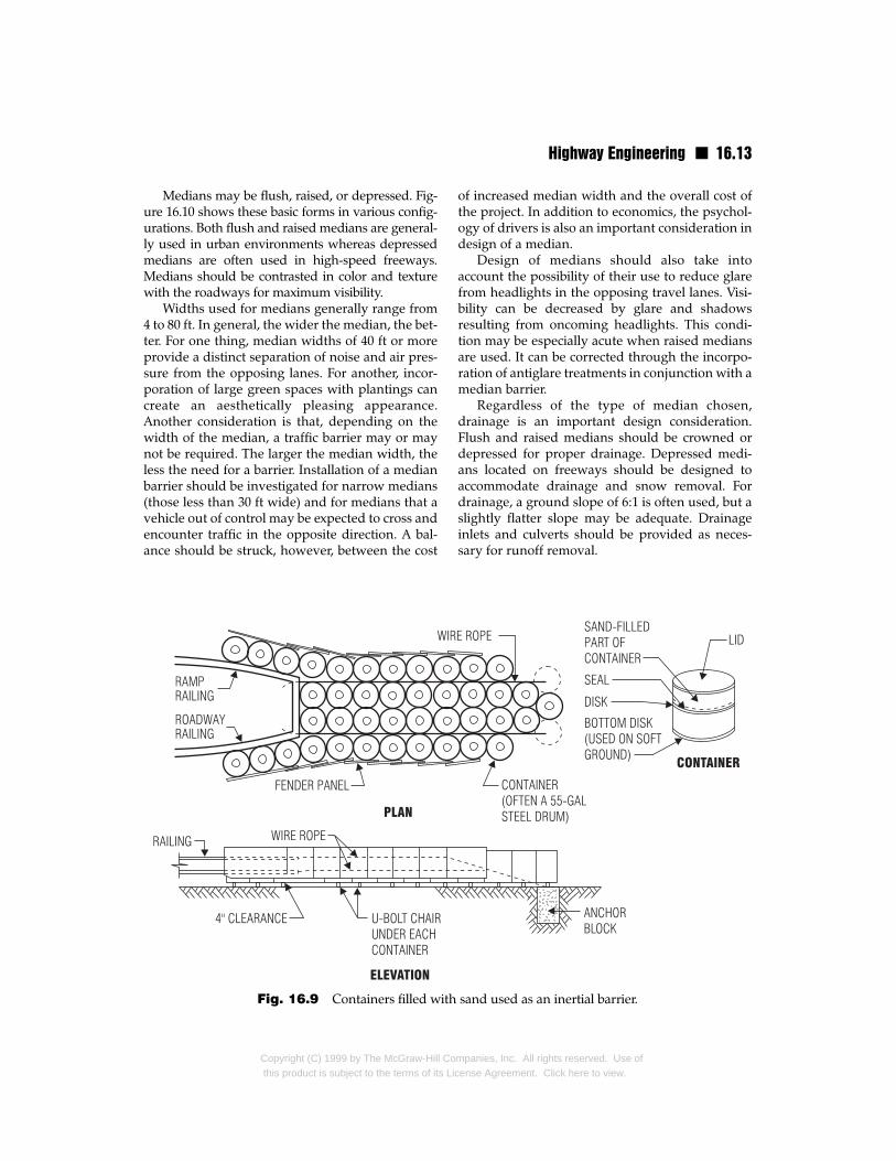
Crash cushions usually are proprietary systemsthat are designed and tested by their manufactur-ers. Most of the systems are based on eitherabsorption of kinetic energy or transfer of momen-tum to an inertial barrier.
Fig. 16.8 Typical barriers for roadways.
Copyright (C) 1999 by The McGraw-Hill Cothis product is subject to the terms of its Lic
To absorb kinetic energy, plastically deformablematerials or hydraulic energy absorbers are placedin the front of the hazard. Dissipation of energy isalso achieved through deformation of the frontportion of an impacting vehicle. Rigid backup orsupport is provided to resist the impact force thatcauses deformation of the crash cushion. The goalof the system is primarily to protect the occupantsof the impacting vehicle from injury and secondar-ily to preserve the integrity of the obstacle.
For transfer of momentum to an inertial barrier,an expendable mass of material is placed in thepath of the vehicle to absorb impact. For example,containers filled with sand may be used as an iner-tial barrier (Fig. 16.9). If a vehicle were to impactsuch a crash cushion, the sand would absorbmomentum from the vehicle. The momentum ofthe vehicle and the sand after impact would equalthe momentum of the vehicle just before theimpact occurred. While theoretically the vehiclewould not come to a stop, the loss in momentumof the vehicle would be sufficient to slow the vehi-cle to a speed of about 10 mi/h after impact withthe last container. Design of crash cushions is typi-cally accomplished through use of manufacturer-supplied design aids and charts.
16.9 Highway MediansA median is a wide strip of a highway used to sep-arate traffic traveling in opposite directions (Fig.16.10). The width of the median in a two-lanehighway is the distance between the inner edges ofthe lanes and includes the shoulders in the medi-an. The width of the median for a highway withtwo or more lanes in each direction is the distancebetween the inner edges of the innermost lanesand includes the shoulders in the median.
In addition to separating the opposing flowsof traffic, a median is designed to accomplish thefollowing:
n Offer a recovery area for errant vehicles
n Provide an area for emergency stopping
n Serve as a safe waiting area for left-turning andU-turning vehicles
n Decrease the amount of headlight glare
n Allow for expansion to future lanes
mpanies, Inc. All rights reserved. Use ofense Agreement. Click here to view.
Highway Engineering n 16.13
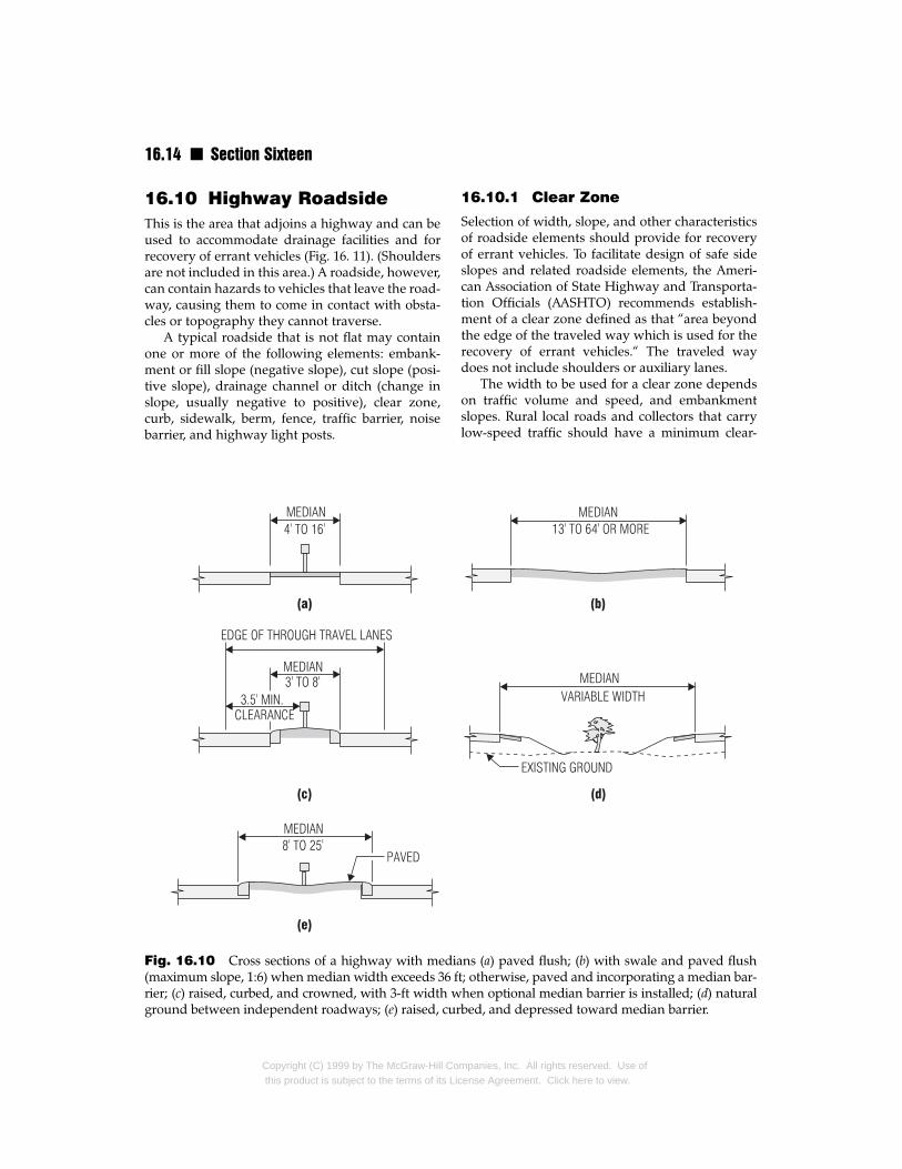
Medians may be flush, raised, or depressed. Fig-ure 16.10 shows these basic forms in various config-urations. Both flush and raised medians are general-ly used in urban environments whereas depressedmedians are often used in high-speed freeways.Medians should be contrasted in color and texturewith the roadways for maximum visibility.
Widths used for medians generally range from4 to 80 ft. In general, the wider the median, the bet-ter. For one thing, median widths of 40 ft or moreprovide a distinct separation of noise and air pres-sure from the opposing lanes. For another, incor-poration of large green spaces with plantings cancreate an aesthetically pleasing appearance.Another consideration is that, depending on thewidth of the median, a traffic barrier may or maynot be required. The larger the median width, theless the need for a barrier. Installation of a medianbarrier should be investigated for narrow medians(those less than 30 ft wide) and for medians that avehicle out of control may be expected to cross andencounter traffic in the opposite direction. A bal-ance should be struck, however, between the cost
Fig. 16.9 Containers filled with
Copyright (C) 1999 by The McGraw-Hill Cothis product is subject to the terms of its Li
of increased median width and the overall cost ofthe project. In addition to economics, the psychol-ogy of drivers is also an important consideration indesign of a median.
Design of medians should also take intoaccount the possibility of their use to reduce glarefrom headlights in the opposing travel lanes. Visi-bility can be decreased by glare and shadowsresulting from oncoming headlights. This condi-tion may be especially acute when raised mediansare used. It can be corrected through the incorpo-ration of antiglare treatments in conjunction with amedian barrier.
Regardless of the type of median chosen,drainage is an important design consideration.Flush and raised medians should be crowned ordepressed for proper drainage. Depressed medi-ans located on freeways should be designed toaccommodate drainage and snow removal. Fordrainage, a ground slope of 6:1 is often used, but aslightly flatter slope may be adequate. Drainageinlets and culverts should be provided as neces-sary for runoff removal.
sand used as an inertial barrier.
mpanies, Inc. All rights reserved. Use ofcense Agreement. Click here to view.
16.14 n Section Sixteen
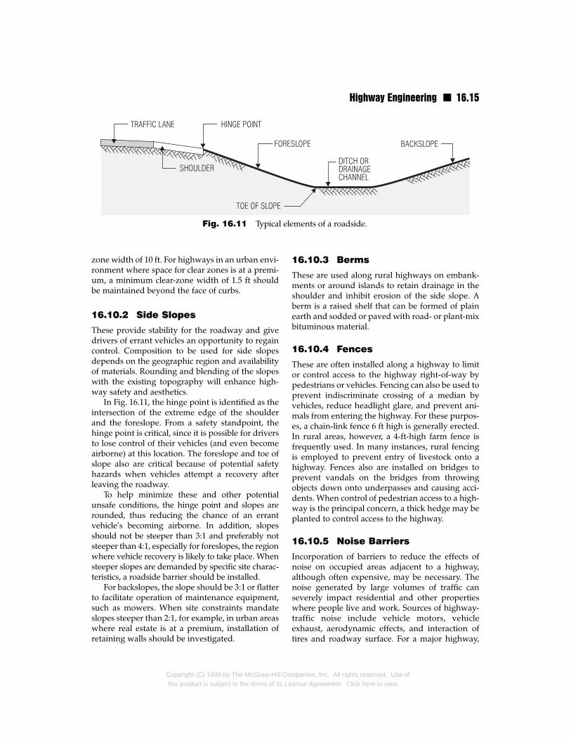
16.10 Highway RoadsideThis is the area that adjoins a highway and can beused to accommodate drainage facilities and forrecovery of errant vehicles (Fig. 16. 11). (Shouldersare not included in this area.) A roadside, however,can contain hazards to vehicles that leave the road-way, causing them to come in contact with obsta-cles or topography they cannot traverse.
A typical roadside that is not flat may containone or more of the following elements: embank-ment or fill slope (negative slope), cut slope (posi-tive slope), drainage channel or ditch (change inslope, usually negative to positive), clear zone,curb, sidewalk, berm, fence, traffic barrier, noisebarrier, and highway light posts.
Fig. 16.10 Cross sections of a highway with medi(maximum slope, 1:6) when median width exceeds 36 frier; (c) raised, curbed, and crowned, with 3-ft width wground between independent roadways; (e) raised, cur
Copyright (C) 1999 by The McGraw-Hill Cothis product is subject to the terms of its Li
16.10.1 Clear Zone
Selection of width, slope, and other characteristicsof roadside elements should provide for recoveryof errant vehicles. To facilitate design of safe sideslopes and related roadside elements, the Ameri-can Association of State Highway and Transporta-tion Officials (AASHTO) recommends establish-ment of a clear zone defined as that “area beyondthe edge of the traveled way which is used for therecovery of errant vehicles.“ The traveled waydoes not include shoulders or auxiliary lanes.
The width to be used for a clear zone dependson traffic volume and speed, and embankmentslopes. Rural local roads and collectors that carrylow-speed traffic should have a minimum clear-
ans (a) paved flush; (b) with swale and paved flusht; otherwise, paved and incorporating a median bar-hen optional median barrier is installed; (d) naturalbed, and depressed toward median barrier.
mpanies, Inc. All rights reserved. Use ofcense Agreement. Click here to view.
Highway Engineering n 16.15
Fig. 16.11 Typical elements of a roadside.
zone width of 10 ft. For highways in an urban envi-ronment where space for clear zones is at a premi-um, a minimum clear-zone width of 1.5 ft shouldbe maintained beyond the face of curbs.
16.10.2 Side Slopes
These provide stability for the roadway and givedrivers of errant vehicles an opportunity to regaincontrol. Composition to be used for side slopesdepends on the geographic region and availabilityof materials. Rounding and blending of the slopeswith the existing topography will enhance high-way safety and aesthetics.
In Fig. 16.11, the hinge point is identified as theintersection of the extreme edge of the shoulderand the foreslope. From a safety standpoint, thehinge point is critical, since it is possible for driversto lose control of their vehicles (and even becomeairborne) at this location. The foreslope and toe ofslope also are critical because of potential safetyhazards when vehicles attempt a recovery afterleaving the roadway.
To help minimize these and other potentialunsafe conditions, the hinge point and slopes arerounded, thus reducing the chance of an errantvehicle’s becoming airborne. In addition, slopesshould not be steeper than 3:1 and preferably notsteeper than 4:1, especially for foreslopes, the regionwhere vehicle recovery is likely to take place. Whensteeper slopes are demanded by specific site charac-teristics, a roadside barrier should be installed.
For backslopes, the slope should be 3:1 or flatterto facilitate operation of maintenance equipment,such as mowers. When site constraints mandateslopes steeper than 2:1, for example, in urban areaswhere real estate is at a premium, installation ofretaining walls should be investigated.
Copyright (C) 1999 by The McGraw-Hill Cothis product is subject to the terms of its Li
16.10.3 Berms
These are used along rural highways on embank-ments or around islands to retain drainage in theshoulder and inhibit erosion of the side slope. Aberm is a raised shelf that can be formed of plainearth and sodded or paved with road- or plant-mixbituminous material.
16.10.4 Fences
These are often installed along a highway to limitor control access to the highway right-of-way bypedestrians or vehicles. Fencing can also be used toprevent indiscriminate crossing of a median byvehicles, reduce headlight glare, and prevent ani-mals from entering the highway. For these purpos-es, a chain-link fence 6 ft high is generally erected.In rural areas, however, a 4-ft-high farm fence isfrequently used. In many instances, rural fencingis employed to prevent entry of livestock onto ahighway. Fences also are installed on bridges toprevent vandals on the bridges from throwingobjects down onto underpasses and causing acci-dents. When control of pedestrian access to a high-way is the principal concern, a thick hedge may beplanted to control access to the highway.
16.10.5 Noise Barriers
Incorporation of barriers to reduce the effects ofnoise on occupied areas adjacent to a highway,although often expensive, may be necessary. Thenoise generated by large volumes of traffic canseverely impact residential and other propertieswhere people live and work. Sources of highway-traffic noise include vehicle motors, vehicleexhaust, aerodynamic effects, and interaction oftires and roadway surface. For a major highway,
mpanies, Inc. All rights reserved. Use ofcense Agreement. Click here to view.
16.16 n Section Sixteen
design, beginning with the preliminary designstage, should take into account the anticipatednoise levels and the type of noise barrier, if any,that will be required.
Noise barriers are sound-absorbing or sound-reflecting walls. They often are fabricated of con-crete, wood, metal, or masonry. The type selectedshould be aesthetically pleasing and blend wellwith the surrounding topography. Local availabili-ty of materials or components and applicable stan-dards often play a critical role in the selection oftypes of noise barriers.
Design and installation of noise barriers for ahighway should conform with the general geo-metric design constraints of the highway. The bar-riers should be set as much as possible away fromthe highway and allow proper sight distance fordrivers. When noise barriers are placed close totraffic, it may be necessary to erect protective bar-riers with the noise barriers.
As an alternative to employment of noise barriers,there are other ways to control the effects of noise onadjacent properties. One method is to depress thehighway below the level of adjacent buildings.Another possibility is elevation of the highway on anembankment or bridge above the level of adjacentbuildings. To further limit noise, shrubs and treesmay be planted or ground covers placed between thehighway and adjoining properties.
16.10.6 Roadside DrainageChannels
A drainage channel is often incorporated in a road-side to collect and convey surface water fordrainage away from the roadbed. To perform thisfunction, drainage channels should be sized forboth design runoff and excessive storm water flows.
A drainage channel usually is a ditch formed byshaping the roadside ground surface (Fig. 16.11).From a hydraulic standpoint, the best drainagechannel is the one with the steepest sides. Therefore,a balance between drainage needs and the need forflatter slopes must be achieved (Art. 16.10.2).
Drainage channels should be located to avoidcreation of a hazard to errant vehicles. Mainte-nance crews should keep the channels free fromdebris, which can reduce the capacity of the chan-nels. They should also ensure that the channels arenot subjected to significant erosion, deposition ofmaterial, or other causes of channel deterioration.
Copyright (C) 1999 by The McGraw-Hill Cothis product is subject to the terms of its Lic
16.11 Right-of-WayThis is the entire area needed for construction,drainage, and maintenance of a highway as well asfor access to and exit from the highway. Achieve-ment of many of the desirable design features dis-cussed in Art. 16.10, such as flatter slopes andproper placement of drainage facilities, is facilitat-ed by procurement of sufficient right-of-way. Inaddition, acquisition of large right-of-way allowsfuture highway expansion to accommodate largertraffic volumes. As a minimum, however, the sizeof the right-of-way acquired for a highway shouldbe at least that required for incorporation of all ele-ments in the design cross section and the appro-priate border areas.
For estimating right-of-way required for a typi-cal ground-level freeway, for example, the crosssection may be assumed to contain 12-ft lanes, 56-ftmedian, 50-ft outer roadsides, 30-ft frontage roads,and 15-ft borders. The American Association ofState Highway and Transportation Officials (AASH-TO) recommends a width of right-of-way of about225 ft for such a freeway with no frontage roadsand 300 to 350 ft with one-way frontage roads onboth sides of the through pavement. For a ground-level freeway with restricted cross section, AASH-TO recommends a width of 100 to 150 ft with nofrontage road and 100 to 200 ft with a two-wayfrontage road on one side. Different sizes of right-of-way are recommended for other types of high-ways (AASHTO “A Policy on Geometric Design ofHighways and Streets”).
16.12 SuperelevationIt is desirable to construct one edge of a roadwayhigher than the other along curves of highways tocounteract centrifugal forces on passengers andvehicles, for the comfort of passengers and to pre-vent vehicles from overturning or sliding off theroad if the centrifugal forces are not counteractedby friction between the roadway and tires. Becauseof the possibility of vehicle sliding when thecurved road is covered with rain, snow, or ice,however, there are limitations on the amount ofsuperelevation that can be used.
The maximum superelevation rate to usedepends on local climate and whether the high-way is classified as rural or urban. Table 16.2 pre-sents typical limits for various design speeds, min-
mpanies, Inc. All rights reserved. Use ofense Agreement. Click here to view.
Highway Engineering n 16.17
Vehicle design velocity, mi/h
30 40 50 60 65 70 75
Ls Ls Ls Ls Ls Ls Ls
e Lanes e Lanes e Lanes e Lanes e Lanes e Lanes e Lanes
2 4 2 4 2 4 2 4 2 4 2 4 2 4
NC 0 0 NC 0 0 NC 0 0 NC 0 0 NC 0 0 NC 0 0 NC 0 0NC 0 0 NC 0 0 NC 0 0 RC 175 175 RC 190 190 RC 200 200 0.022 220 220NC 0 0 NC 0 0 RC 150 150 0.022 175 175 0.025 190 190 0.029 200 200 0.032 220 220NC 0 0 RC 125 125 0.021 150 150 0.029 175 175 0.053 190 190 0.038 200 200 0.043 220 220RC 100 100 0.021 125 125 0.030 150 150 0.040 175 175 0.046 190 200 0.053 200 240 0.080 220 290RC 100 100 0.027 125 125 0.038 150 150 0.051 175 210 0.057 190 250 0.065 200 290 0.072 230 3400.021 100 100 0.033 125 125 0.046 150 170 0.060 175 240 0.066 190 290 0.073 220 330 0.078 250 3700.025 100 100 0.038 125 125 0.053 150 190 0.067 180 270 0.073 210 320 0.073 230 350 0.080 250 3800.028 100 100 0.043 125 140 0.058 150 210 0.073 200 300 0.077 220 330 0.080 240 380 0.080 250 380
0.052 100 100 0.047 125 150 0.063 150 230 0.077 210 310 0.079 230 340 0.080 240 360 Dc max = 3.0°
0.038 100 100 0.055 125 170 0.071 170 260 0.080 220 320 0.080 230 350 Dc max = 3.5°
0.043 100 120 0.061 130 190 0.077 180 280 0.080 220 320 Dc max = 4.5°
0.048 100 130 0.067 140 210 0.079 190 280 Dc max = 5.0°
0.052 100 140 0.071 150 220 0.080 190 290
0.056 100 150 0.075 160 240 Dc max = 7.5°
0.059 110 160 0.077 160 2400.063 110 170 0.079 170 2500.066 120 180 0.080 170 2300.068 120 180 0.080 170 250
0.070 130 190 Dc max = 12.5°
0.074 130 2000.077 140 2100.079 140 2100.080 140 2200.080 140 220
Dc max = 23.0°
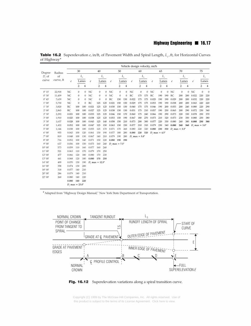
Table 16.2 Superelevation e, in/ft, of Pavement Width and Spiral Length, Ls , ft, for Horizontal Curvesof Highway*
0° 15’ 22,9180° 30’ 11,4590° 45’ 7,6391° 00’ 5,7301° 30’ 3,8202° 00’ 2,8652° 30’ 2,2923° 00’ 1,9103° 30’ 1,6374° 00’ 1,4325° 00’ 1,1466° 00’ 9557° 00’ 8198° 00’ 7169° 00’ 637
10° 00’ 57311° 00’ 52112° 00’ 47713° 00’ 44114° 00’ 40916° 00’ 35818° 00’ 31820° 00’ 28622° 00’ 260
DegreeDc ofcurve
Radiusof
curve, ft
*Adapted from “Highway Design Manual,” New York State Department of Transportation.
Fig. 16.12 Superelevation variations along a spiral transition curve.
Copyright (C) 1999 by The McGraw-Hill Companies, Inc. All rights reserved. Use ofthis product is subject to the terms of its License Agreement. Click here to view.
16.18 n Section Sixteen
imum radii, superelevation rates e, and transitionspiral lengths Ls. The last is the distance over whichthe normal crown cross section changes to a fullybanked section as the roadway alignment changesfrom tangent to start of a circular curve.
For the safety and comfort of drivers, provisionusually is made for gradual change from a tangentto the start of a circular curve. One method fordoing this is to insert a spiral curve between thosesections of the roadway (Art. 16.13.3). A spiral pro-vides a comfortable path for drivers since the radiusof curvature of the spiral gradually decreases to thatof the circular curve while the superelevation grad-ually increases from zero to full superelevation ofthe circular curve. A similar transition is inserted atthe end of the circular curve. (An alternative is toutilize compound curves that closely approximate aspiral.) Over the length of the transition, the center-line of each roadway is maintained at profile gradewhile the outer edge of the roadway is raised andthe inner edge is lowered to produce the requiredsuperelevation. As indicated in Fig. 16.12, typicallythe outer edge is raised first until the outer half ofthe cross section is level with the crown (point B).Then, the outer edge is raised further until the crosssection is straight (point C). From there on, theentire cross section is rotated until the full superele-vation is attained (point E). See also Art. 16.13.4.
Superelevated roadway cross sections are typical-ly employed on curves of rural highways and urbanfreeways. Superelevation is rarely used on localstreets in residential, commercial, or industrial areas.
Highway AlignmentsGeometric design of a highway is concerned withhorizontal and vertical alignment as well as thecross-sectional elements discussed in Arts. 16.2 to16.12. Horizontal alignment of a highway definesits location and orientation in plan view. Verticalalignment of a highway deals with its shape in pro-file. For a roadway with contiguous travel lanes,alignment can be conveniently represented by thecenterline of the roadway.
16.13 Horizontal AlignmentThis comprises one or more of the following geo-metric elements: tangents (straight sections), circu-lar curves (Art 16.13.2), and transition spirals (Arts.16.12 and 16.13.3).
Copyright (C) 1999 by The McGraw-Hill Cothis product is subject to the terms of its Lic
16.13.1 Stationing
Distance along a horizontal alignment is measuredin terms of stations. A full station is defined as 100ft and a half station as 50 ft. Station 100 + 50 is 150ft from the start of the alignment, Station 0 + 00. Apoint 1492.27 ft from 0 + 00 is denoted as 14 +92.27, indicating a location 14 stations (1400 ft) plus92.27 ft from the starting point of the alignment.This distance is measured horizontally along thecenterline of the roadway, whether it is a tangent,curve, or a combination of these.
16.13.2 Simple Curves
A simple horizontal curve consists of a part of a cir-cle tangent to two straight sections on the horizon-tal alignment. The radius of a curve preferablyshould be large enough that drivers do not feelcompelled to slow their vehicles. Such a radius,however, is not always feasible, inasmuch as thealignment should blend harmoniously with theexisting topography as much as possible and bal-ance other design considerations, such as overallproject economy, sight distance, and side friction.Superelevation, usually employed on curves withsharp curvature, also should be taken into account(Art. 16.12).
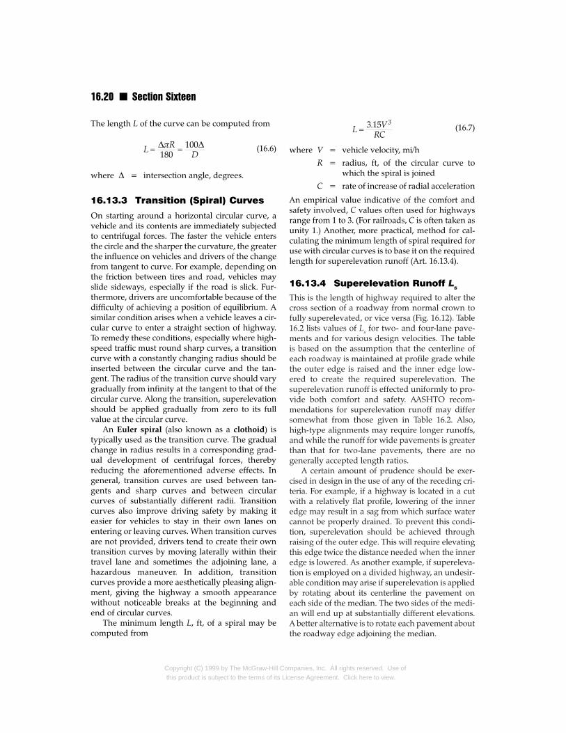
A curve begins at a point designated point ofcurvature or PC. There, the curve is tangent to thestraight section of the alignment, which is called atangent (Fig. 16.13). The curve ends at the point oftangency PT, where the curve is tangent to anotherstraight section of the alignment. The angle ∆formed at PI, the point of intersection of the two tan-gents, is called the interior angle or intersection angle.
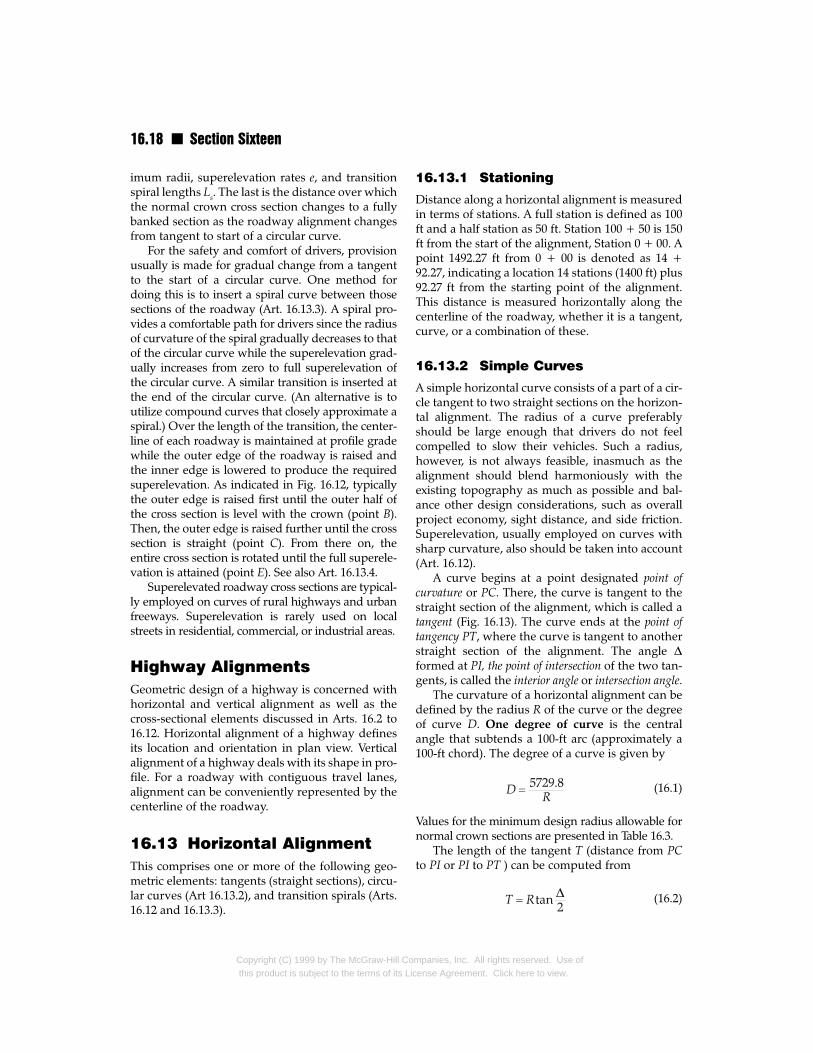
The curvature of a horizontal alignment can bedefined by the radius R of the curve or the degreeof curve D. One degree of curve is the centralangle that subtends a 100-ft arc (approximately a100-ft chord). The degree of a curve is given by
(16.1)
Values for the minimum design radius allowable fornormal crown sections are presented in Table 16.3.
The length of the tangent T (distance from PCto PI or PI to PT ) can be computed from
(16.2)
mpanies, Inc. All rights reserved. Use ofense Agreement. Click here to view.
Highway Engineering n 16.19
The external distance E measured from PI to thecurve on a radial line is given by
(16.3)
The middle ordinate distance M extends from themidpoint B of the chord to the midpoint A of thecurve.
Design Averagespeed, runningmi/h speed, mi/h
20 2030 2840 3650 4455 4860 5265 5570 58
*Adapted from “A Policy on Geometric Design of Highways and StOfficials.
Table 16.3 Maximum Curvature for Normal Crow
Fig. 16.13 Circular curve starting at point PC on onintersects the first one at PI. Curve radius is R and choLC. Tangent distance is T.
Copyright (C) 1999 by The McGraw-Hill Cothis product is subject to the terms of its Li
(16.4)
The length of the chord C from PC to PT is given by
(16.5)
Maximum Minimumdegree of curve
curve radius, ft
3° 23’ 1,7001° 43’ 3,3401° 02’ 5,5500° 41’ 8,3200° 35’ 9,9300° 29’ 11,6900° 26’ 13,1400° 23’ 14,690
reets,” American Association of State Highway and Transportation
n Section*
e tangent and ending at PT on a second tangent thatrd distance between PC and PT is C. Length of arc is
mpanies, Inc. All rights reserved. Use ofcense Agreement. Click here to view.
16.20 n Section Sixteen
The length L of the curve can be computed from
(16.6)
where ∆ = intersection angle, degrees.
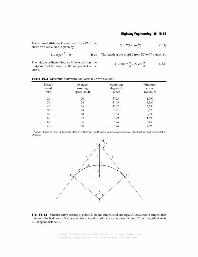
16.13.3 Transition (Spiral) Curves
On starting around a horizontal circular curve, avehicle and its contents are immediately subjectedto centrifugal forces. The faster the vehicle entersthe circle and the sharper the curvature, the greaterthe influence on vehicles and drivers of the changefrom tangent to curve. For example, depending onthe friction between tires and road, vehicles mayslide sideways, especially if the road is slick. Fur-thermore, drivers are uncomfortable because of thedifficulty of achieving a position of equilibrium. Asimilar condition arises when a vehicle leaves a cir-cular curve to enter a straight section of highway.To remedy these conditions, especially where high-speed traffic must round sharp curves, a transitioncurve with a constantly changing radius should beinserted between the circular curve and the tan-gent. The radius of the transition curve should varygradually from infinity at the tangent to that of thecircular curve. Along the transition, superelevationshould be applied gradually from zero to its fullvalue at the circular curve.
An Euler spiral (also known as a clothoid) istypically used as the transition curve. The gradualchange in radius results in a corresponding grad-ual development of centrifugal forces, therebyreducing the aforementioned adverse effects. Ingeneral, transition curves are used between tan-gents and sharp curves and between circularcurves of substantially different radii. Transitioncurves also improve driving safety by making iteasier for vehicles to stay in their own lanes onentering or leaving curves. When transition curvesare not provided, drivers tend to create their owntransition curves by moving laterally within theirtravel lane and sometimes the adjoining lane, ahazardous maneuver. In addition, transitioncurves provide a more aesthetically pleasing align-ment, giving the highway a smooth appearancewithout noticeable breaks at the beginning andend of circular curves.
The minimum length L, ft, of a spiral may becomputed from
Copyright (C) 1999 by The McGraw-Hill Cothis product is subject to the terms of its Lic
(16.7)
where V = vehicle velocity, mi/h
R = radius, ft, of the circular curve towhich the spiral is joined
C = rate of increase of radial acceleration
An empirical value indicative of the comfort andsafety involved, C values often used for highwaysrange from 1 to 3. (For railroads, C is often taken asunity 1.) Another, more practical, method for cal-culating the minimum length of spiral required foruse with circular curves is to base it on the requiredlength for superelevation runoff (Art. 16.13.4).
16.13.4 Superelevation Runoff Ls
This is the length of highway required to alter thecross section of a roadway from normal crown tofully superelevated, or vice versa (Fig. 16.12). Table16.2 lists values of Ls for two- and four-lane pave-ments and for various design velocities. The tableis based on the assumption that the centerline ofeach roadway is maintained at profile grade whilethe outer edge is raised and the inner edge low-ered to create the required superelevation. Thesuperelevation runoff is effected uniformly to pro-vide both comfort and safety. AASHTO recom-mendations for superelevation runoff may differsomewhat from those given in Table 16.2. Also,high-type alignments may require longer runoffs,and while the runoff for wide pavements is greaterthan that for two-lane pavements, there are nogenerally accepted length ratios.
A certain amount of prudence should be exer-cised in design in the use of any of the receding cri-teria. For example, if a highway is located in a cutwith a relatively flat profile, lowering of the inneredge may result in a sag from which surface watercannot be properly drained. To prevent this condi-tion, superelevation should be achieved throughraising of the outer edge. This will require elevatingthis edge twice the distance needed when the inneredge is lowered. As another example, if supereleva-tion is employed on a divided highway, an undesir-able condition may arise if superelevation is appliedby rotating about its centerline the pavement oneach side of the median. The two sides of the medi-an will end up at substantially different elevations.A better alternative is to rotate each pavement aboutthe roadway edge adjoining the median.
mpanies, Inc. All rights reserved. Use ofense Agreement. Click here to view.
Highway Engineering n 16.21
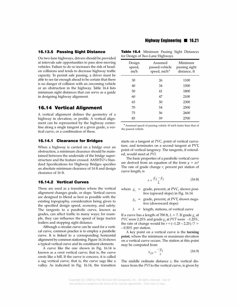
16.13.5 Passing Sight Distance
On two-lane highways, drivers should be providedat intervals safe opportunities to pass slow-movingvehicles. Failure to do so increases the risk of head-on collisions and tends to decrease highway trafficcapacity. To permit safe passing, a driver must beable to see far enough ahead to be certain that thereis no danger of collision with an oncoming vehicleor an obstruction in the highway. Table 16.4 listsminimum sight distances that can serve as a guidein designing highway alignment.
16.14 Vertical AlignmentA vertical alignment defines the geometry of ahighway in elevation, or profile. A vertical align-ment can be represented by the highway center-line along a single tangent at a given grade, a ver-tical curve, or a combination of these.
16.14.1 Clearance for Bridges
When a highway is carried on a bridge over anobstruction, a minimum clearance should be main-tained between the underside of the bridge super-structure and the feature crossed. AASHTO’s Stan-dard Specifications for Highway Bridges specifiesan absolute minimum clearance of 14 ft and designclearance of 16 ft.
16.14.2 Vertical Curves
These are used as a transition where the verticalalignment changes grade, or slope. Vertical curvesare designed to blend as best as possible with theexisting topography, consideration being given tothe specified design speed, economy, and safety.The tangents to a parabolic curve, known asgrades, can affect traffic in many ways; for exam-ple, they can influence the speed of large tractortrailers and stopping sight distance.
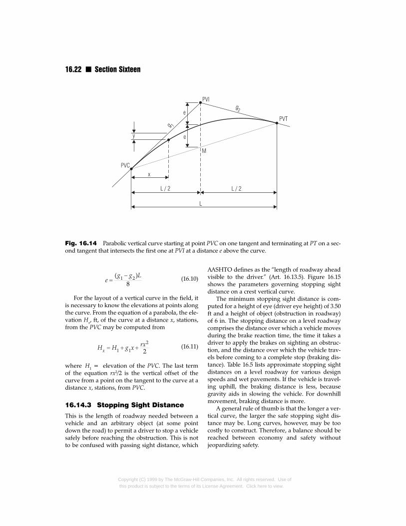
Although a circular curve can be used for a verti-cal curve, common practice is to employ a paraboliccurve. It is linked to a corresponding horizontalalignment by common stationing. Figure 16.14 showsa typical vertical curve and its constituent elements.
A curve like the one shown in Fig. 16.14 isknown as a crest vertical curve; that is, the curvecrests like a hill. If the curve is concave, it is calleda sag vertical curve; that is, the curve sags like avalley. As indicated in Fig. 16.14, the transition
Copyright (C) 1999 by The McGraw-Hill Cothis product is subject to the terms of its Li
starts on a tangent at PVC, point of vertical curva-ture, and terminates on a second tangent at PVT,point of vertical tangency. The tangents, if extend-ed, would meet at PVI.
The basic properties of a parabolic vertical curveare derived from an equation of the form y = ax2
The rate of grade change r, percent per station ofcurve length, is
(16.8)
where g1 = grade, percent, at PVC, shown posi-tive (upward slope) in Fig. 16.14
g2 = grade, percent, at PVT, shown nega-tive (downward slope)
L = length, stations, of vertical curve
If a curve has a length of 700 ft, L = 7. If grade g1 atPVC were 2.25% and grade g2 at PVT were –1.25%,the rate of change would be r =(–1.25 – 2.25) / 7 =– 0.50% per station.
A key point on a vertical curve is the turning
point, where the minimum or maximum elevationon a vertical curve occurs. The station at this pointmay be computed from
(16.9)
The middle ordinate distance e, the vertical dis-tance from the PVI to the vertical curve, is given by
Design Assumed Minimumspeed, passed-vehicle passing sightmi/h speed, mi/h* distance, ft
30 26 1100
40 34 1500
50 41 1800
60 47 2100
65 50 2300
70 54 2500
75 56 2600
85 59 2700
*Assumed speed of passing vehicle 10 mi/h faster than that ofthe passed vehicle.
Table 16.4 Minimum Passing Sight Distancesfor Design of Two-Lane Highways
mpanies, Inc. All rights reserved. Use ofcense Agreement. Click here to view.
16.22 n Section Sixteen
Fig. 16.14 Parabolic vertical curve starting at point PVC on one tangent and terminating at PT on a sec-ond tangent that intersects the first one at PVI at a distance e above the curve.
(16.10)
For the layout of a vertical curve in the field, itis necessary to know the elevations at points alongthe curve. From the equation of a parabola, the ele-vation Hx, ft, of the curve at a distance x, stations,from the PVC may be computed from
(16.11)
where H1 = elevation of the PVC. The last termof the equation rx2/2 is the vertical offset of thecurve from a point on the tangent to the curve at adistance x, stations, from PVC.
16.14.3 Stopping Sight Distance
This is the length of roadway needed between avehicle and an arbitrary object (at some pointdown the road) to permit a driver to stop a vehiclesafely before reaching the obstruction. This is notto be confused with passing sight distance, which
Copyright (C) 1999 by The McGraw-Hill Cothis product is subject to the terms of its Lic
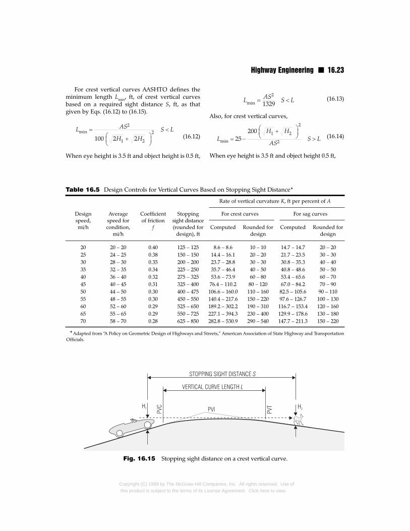
AASHTO defines as the “length of roadway aheadvisible to the driver.” (Art. 16.13.5). Figure 16.15shows the parameters governing stopping sightdistance on a crest vertical curve.
The minimum stopping sight distance is com-puted for a height of eye (driver eye height) of 3.50ft and a height of object (obstruction in roadway)of 6 in. The stopping distance on a level roadwaycomprises the distance over which a vehicle movesduring the brake reaction time, the time it takes adriver to apply the brakes on sighting an obstruc-tion, and the distance over which the vehicle trav-els before coming to a complete stop (braking dis-tance). Table 16.5 lists approximate stopping sightdistances on a level roadway for various designspeeds and wet pavements. If the vehicle is travel-ing uphill, the braking distance is less, becausegravity aids in slowing the vehicle. For downhillmovement, braking distance is more.
A general rule of thumb is that the longer a ver-tical curve, the larger the safe stopping sight dis-tance may be. Long curves, however, may be toocostly to construct. Therefore, a balance should bereached between economy and safety withoutjeopardizing safety.
mpanies, Inc. All rights reserved. Use ofense Agreement. Click here to view.
Highway Engineering n 16.23
For crest vertical curves AASHTO defines theminimum length Lmin, ft, of crest vertical curvesbased on a required sight distance S, ft, as thatgiven by Eqs. (16.12) to (16.15).
(16.12)
When eye height is 3.5 ft and object height is 0.5 ft,
Design Average Coefficient Stoppingspeed, speed for of friction sight distancemi/h condition, f (rounded for
mi/h design), ft
20 20 – 20 0.40 125 – 12525 24 – 25 0.38 150 – 15030 28 – 30 0.35 200 – 20035 32 – 35 0.34 225 – 25040 36 – 40 0.32 275 – 32545 40 – 45 0.31 325 – 40050 44 – 50 0.30 400 – 47555 48 – 55 0.30 450 – 55060 52 – 60 0.29 525 – 65065 55 – 65 0.29 550 – 72570 58 – 70 0.28 625 – 850
*Adapted from “A Policy on Geometric Design of Highways and StOfficials.
Table 16.5 Design Controls for Vertical Curves Bas
Fig. 16.15 Stopping sight dis
Copyright (C) 1999 by The McGraw-Hill Cothis product is subject to the terms of its Li
(16.13)
Also, for crest vertical curves,
(16.14)
When eye height is 3.5 ft and object height 0.5 ft,
Rate of vertical curvature K, ft per percent of A
For crest curves For sag curves
Computed Rounded for Computed Rounded fordesign design
8.6 – 8.6 10 – 10 14.7 – 14.7 20 – 2014.4 – 16.1 20 – 20 21.7 – 23.5 30 – 3023.7 – 28.8 30 – 30 30.8 – 35.3 40 – 4035.7 – 46.4 40 – 50 40.8 – 48.6 50 – 5053.6 – 73.9 60 – 80 53.4 – 65.6 60 – 7076.4 – 110.2 80 – 120 67.0 – 84.2 70 – 90
106.6 – 160.0 110 – 160 82.5 – 105.6 90 – 110140.4 – 217.6 150 – 220 97.6 – 126.7 100 – 130189.2 – 302.2 190 – 310 116.7 – 153.4 120 – 160227.1 – 394.3 230 – 400 129.9 – 178.6 130 – 180282.8 – 530.9 290 – 540 147.7 – 211.3 150 – 220
reets,” American Association of State Highway and Transportation
ed on Stopping Sight Distance*
tance on a crest vertical curve.
mpanies, Inc. All rights reserved. Use ofcense Agreement. Click here to view.
16.24 n Section Sixteen
(16.15)
where A = algebraic difference in grades, per-cent, of the tangents to the verticalcurve
H1 = eye height, ft, above the pavement
H2 = object height, ft, above the pave-ment
Design controls for vertical curves can be estab-lished in terms of the rate of vertical curvature Kdefined by
(16.16)
where L = length, ft, of vertical curve and A isdefined above. K is useful in determining the min-imum sight distance, the length of a vertical curvefrom the PVC to the turning point (maximumpoint on a crest and minimum on a sag). This dis-tance is found by multiplying K by the approachgradient.
Table 16.5 lists recommended values of K forvarious design velocities and stopping sight dis-tances for crest and sag vertical curves.
Highway DrainageProper drainage is a very important considerationin design of a highway. Inadequate drainage facili-ties can lead to premature deterioration of the high-way and the development of adverse safety condi-tions such as hydroplaning. It is common, therefore,for a sizable portion of highway construction bud-gets to be devoted to drainage facilities.
In essence, the general function of a highwaydrainage system is to remove rainwater from theroad and water from the highway right-of-way. Thedrainage system should provide for the drainageconditions described in Arts. 16.16 and 16.17.
16.15 Storm Frequency andRunoff
Storm frequency refers to the chance that a givenintensity of rainfall will occur within a specific spanof years. It is determined from historical data thatindicate that a particular intensity of rainfall can be
Copyright (C) 1999 by The McGraw-Hill Cothis product is subject to the terms of its Lic
expected once in N years. A drainage systemdesigned for such an intensity is intended to becapable of withstanding an N-year storm, runoff, orflood. A 25-year storm, for example, represents a 1in 25 probability that the drainage system will haveto accommodate such an intensity. This does notmean that every 25 years a certain storm of thismagnitude will occur. It is possible that such a stormwill not occur at all during any 25-year period. It isalso possible, however, that two or more suchstorms will take place in a single year. The odds ofthis happening, though, are relatively small.
For highways, cross drains (small culverts)passed under major highways to carry the flowfrom defined watercourses are typically designedto accommodate a 25-year storm. Larger culvertsand bridges on major highways are designed withcapacity for 100-year storms. For nonmajor high-ways, the storm used for design can range from a10- to 50-year storm, depending on the highwaysize and traffic volume expected.
Runoff Determination n The amount ofrunoff to be used for design of surface drainagecan be determined through physical stream-flowmeasurements or through the use of empirical for-mulas. A common approach is to utilize the ratio-nal method described in Art. 21.39 (also known asthe Lloyd-Davies method in the United Kingdom).While this approach gives reasonable answers inmost urban areas, care must be taken when apply-ing the rational method in rural areas. Runoff forrural and large watershed areas is much more dif-ficult to estimate accurately than the runoff inurban environments. Typically, for determinationof runoff, a large watershed is divided into severalsmaller watershed areas, from which runoff flowsto various inlets or waterways. In general, conser-vative design values of runoff can be determinedfor drainage areas of 100 acres or less. Somedesigners, however, have used 200-acre and even500-acre maximum values.
16.16 Surface DrainageProvision must be made for removal of water, fromrain or melting snow, or both, that falls directly on aroad or comes from the adjacent terrain. The roadshould be adequately sloped to drain the wateraway from the travel lanes and shoulders and thendirected to drainage channels in the system, such as
mpanies, Inc. All rights reserved. Use ofense Agreement. Click here to view.
Highway Engineering n 16.25
natural earth swales, concrete gutters, and ditches,for discharge to an adjacent body of water. Thechannels should be located and shaped to minimizethe potential for traffic hazards and accommodatethe anticipated storm-water flows. Drainage inletsshould be provided as needed to prevent pondingand limit the spread of water into traffic lanes.
16.16.1 Surface Drainage Methods
For rural highways on embankments, runoff fromthe roadway should be allowed to flow evenlyover the side slopes and then spread over the adja-cent terrain. This method, however, can sometimesadversely impact surrounding land, such as farms.In such instances the drainage should be collected,for example, in longitudinal ditches and then con-veyed to a nearby watercourse.
When a highway is located in a cut, runoff maybe collected in shallow side ditches. These typical-ly have a trapezoidal, triangular, or rounded crosssection and should be deep enough to drain thepavement subbase and convey the design-stormflow to a discharge point. Care should be taken todesign the ditches so that the toe of adjoining slop-ing fill does not suffer excessive erosion. For largerwater flows than the capacity of a shallow ditch,paved gutters or drainpipes with larger capacitieswill have to be used.
In urban environments and built-up areas, useof roadside drainage channels may be severelylimited by surrounding land uses. In mostinstances, the cost of acquiring the necessary right-of-way to implement such drainage facilities is pro-hibitive. For highways on embankments, a curb oran earth berm may be constructed along the outeredge of the roadway to intercept runoff and divertit to inlets placed at regular intervals. The inlets, inturn, should be connected to storm sewers thatconvey the water to points of disposal. In an urbanarea, it may be necessary to construct storm sewersof considerable length to reach the nearest body ofwater for discharge of the runoff.
16.16.2 InletsThese are parts of a drainage system that receiverunoff at grade and permit the water to flowdownward into underground storm drains. Inletsshould be capable of passing design floods withoutclogging with debris. The entrance to inlets shouldbe protected with a grating set flush with the sur-
Copyright (C) 1999 by The McGraw-Hill Cothis product is subject to the terms of its Li
face of gutters or medians, so as not to be a hazardto vehicles. There are several types of inlets.
A drop inlet is a box-type structure that is locat-ed in pipe segments of a storm-water collectionsystem and into which storm water enters from thetop. Most municipal agencies maintain design andconstruction standards for a wide variety of inlets,manholes, and other similar structures, but somelarge structures may require site-specific design.
A curb inlet consists of a vertical opening in acurb through which gutter flow passes. A gutter
inlet is a horizontal opening in the gutter that isprotected by a single grate or multiple gratesthrough which the gutter flow passes. A combina-
tion inlet consists of both gutter and curb inletswith the gutter inlet placed in front of the curb inlet.
Inlet spacing depends on the quantity of waterto be intercepted, shape of ditch or gutter convey-ing the water, and hydraulic capacity of the inlet.
16.16.3 Storm Sewers
These are underground pipes that receive therunoff from a roadside inlet for conveyance anddischarge into a body of water away from the road.Storm sewers are often sized for anticipated runoffand for pipe capacity determined from the Man-ning formula (Art. 21.9).
In general, changes in sewer direction are madeat inlets, catch basins, or manholes.
The manholes should provide maintenanceaccess to sewers at about every 500 ft.
A storm sewer system for a new highwayshould be connected to an existing drainage sys-tem, such as a stream or existing storm sewer sys-tem. If a storm sewer is to connect to a stream, thedownstream conditions should be investigated toensure that the waterway is adequate and that thenew system will not have an adverse environmen-tal impact. If the environmental impact is notacceptable, it will be necessary to study possibleimprovements to downstream outlets to accom-modate the additional flow or to make thedrainage scheme acceptable to local officials insome other fashion.
16.16.4 Open ChannelsAs indicated in Art. 16.16.1, side ditches may beused to collect runoff from a highway located in acut. The ditches may be trapezoidal or V-shaped.The trapezoidal ditch has greater capacity for a
mpanies, Inc. All rights reserved. Use ofcense Agreement. Click here to view.
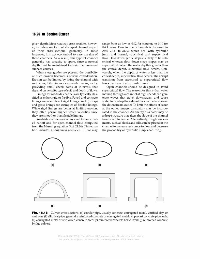
16.26 n Section Sixteen
given depth. Most roadway cross sections, howev-er, include some form of V-shaped channel as partof their cross-sectional geometry. In mostinstances, it is not economical to vary the size ofthese channels. As a result, this type of channelgenerally has capacity to spare, since a normaldepth must be maintained to drain the pavementsubbase courses.
When steep grades are present, the possibilityof ditch erosion becomes a serious consideration.Erosion can be limited by lining the channel withsod, stone, bituminous or concrete paving, or byproviding small check dams at intervals thatdepend on velocity, type of soil, and depth of flows.
Linings for roadside channels are typically clas-sified as either rigid or flexible. Paved and concretelinings are examples of rigid linings. Rock (riprap)and grass linings are examples of flexible linings.While rigid linings are better at limiting erosion,they often permit higher water velocities sincethey are smoother than flexible linings.
Roadside channels are often sized for anticipat-ed runoff and for open-channel flow computedfrom the Manning equation (Art. 21.24). This equa-tion includes a roughness coefficient n that may
Fig. 16.16 Culvert cross sections: (a) circular pipe, cast iron; (b) elliptical pipe, generally reinforced concret(d) corrugated metal or reinforced concrete arch; (e) reibridge culvert.
Copyright (C) 1999 by The McGraw-Hill Cothis product is subject to the terms of its Lic
range from as low as 0.02 for concrete to 0.10 forthick grass. Flow in open channels is discussed inArts. 21.23 to 21.33, which deal with hydraulicjump and normal, subcritical, and supercriticalflow. Flow down gentle slopes is likely to be sub-critical whereas flow down steep slopes may besupercritical. When the water depth is greater thanthe critical depth, subcritical flow occurs. Con-versely, when the depth of water is less than thecritical depth, supercritical flow occurs. The abrupttransition from subcritical to supercritical flowtakes the form of a hydraulic jump.
Open channels should be designed to avoidsupercritical flow. The reason for this is that watermoving through a channel at high speeds can gen-erate waves that travel downstream and causewater to overtop the sides of the channel and scourthe downstream outlet. To limit the effects of scourat the outlet, energy dissipators may be incorpo-rated in the channel. An energy dissipator may bea drop structure that alters the slope of the channelfrom steep to gentle. Alternatively, roughness ele-ments, such as blocks and sills, can be placed in thechannel to increase resistance to flow and decreasethe probability of hydraulic jump’s occurring.
usually concrete, corrugated metal, vitrified clay, ore or corrugated metal; (c) precast concrete pipe arch;nforced concrete box culvert; (f) reinforced concrete
mpanies, Inc. All rights reserved. Use ofense Agreement. Click here to view.
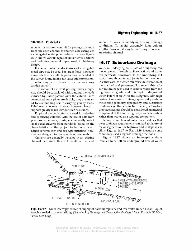
Highway Engineering n 16.27
16.16.5 Culverts
A culvert is a closed conduit for passage of runofffrom one open channel to another. One example isa corrugated metal pipe under a roadway. Figure16.16 shows various types of culvert cross sectionsand indicates material types used in highwaydesign.
For small culverts, stock sizes of corrugatedmetal pipe may be used. For larger flows, however,a concrete box or multiple pipes may be needed. Ifthe culvert foundation is not susceptible to erosion,a bridge may be constructed over the waterway(bridge culvert).
The section of a culvert passing under a high-way should be capable of withstanding the loadsinduced by traffic passing over the culvert. Sincecorrugated metal pipes are flexible, they are assist-ed by surrounding soil in carrying gravity loads.Reinforced concrete culverts, however, have tosupport gravity loads without such assistance.
Empirical methods often are used for selectingand specifying culverts. With the use of data fromprevious experience, designers generally selectsmall-sized culverts from standards based on thecharacteristics of the project to be constructed.Larger concrete arch and box-type structures, how-ever, are designed for the specific service loads.
Culverts are generally installed in an existingchannel bed since this will result in the least
Fig. 16.17 Drain intercepts source of supply of hatrench is sealed to prevent silting. (“Handbook of DrainaArmco Steel Corp.)
Copyright (C) 1999 by The McGraw-Hill Cothis product is subject to the terms of its Li
amount of work in modifying existing drainageconditions. To avoid extremely long culvertlengths, however, it may be necessary to relocatean existing channel.
16.17 Subsurface DrainageWater in underlying soil strata of a highway canmove upward through capillary action and watercan permeate downward to the underlying soilstrata through cracks and joints in the pavement.In either case, the water can cause deterioration ofthe roadbed and pavement. To prevent this, sub-surface drainage is used to remove water from thehighway subgrade and intercept undergroundwater before it flows to the subgrade. Althoughdesign of subsurface drainage systems depends onthe specific geometry, topography, and subsurfaceconditions of the site to be drained, subsurfacedrainage facilities should be considered an integralcomponent of the entire highway drainage systemrather than treated as a separate component.
Failure to implement subsurface facilities thatmeet drainage requirements can lead to failure ofmajor segments of the highway and to slope insta-bility. Figures 16.17 to Fig. 16.19 illustrate somecommonly used subgrade drainage methods.
Figure 16.17 shows an intercepting draininstalled to cut off an underground flow of water
rmful capillary and free water under a road. Top ofge and Construction Products,” Metal Products Division,
mpanies, Inc. All rights reserved. Use ofcense Agreement. Click here to view.
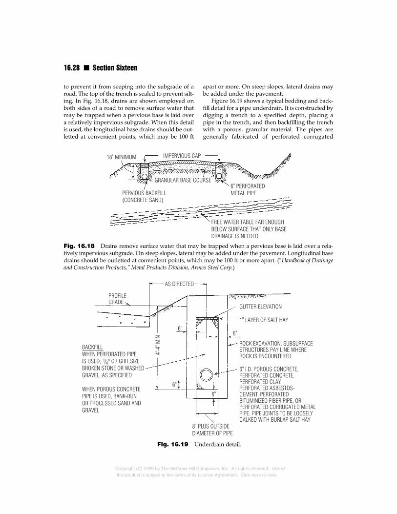
16.28 n Section Sixteen
to prevent it from seeping into the subgrade of aroad. The top of the trench is sealed to prevent silt-ing. In Fig. 16.18, drains are shown employed onboth sides of a road to remove surface water thatmay be trapped when a pervious base is laid overa relatively impervious subgrade. When this detailis used, the longitudinal base drains should be out-letted at convenient points, which may be 100 ft
Fig. 16.18 Drains remove surface water that may btively impervious subgrade. On steep slopes, lateral madrains should be outletted at convenient points, whichand Construction Products,” Metal Products Division, Arm
Fig. 16.19 Un
Copyright (C) 1999 by The McGraw-Hill Cothis product is subject to the terms of its Li
apart or more. On steep slopes, lateral drains maybe added under the pavement.
Figure 16.19 shows a typical bedding and back-fill detail for a pipe underdrain. It is constructed bydigging a trench to a specified depth, placing apipe in the trench, and then backfilling the trenchwith a porous, granular material. The pipes aregenerally fabricated of perforated corrugated
e trapped when a pervious base is laid over a rela-y be added under the pavement. Longitudinal base may be 100 ft or more apart. (“Handbook of Drainageco Steel Corp.)
derdrain detail.
mpanies, Inc. All rights reserved. Use ofcense Agreement. Click here to view.
Highway Engineering n 16.29
metal pipe, vitrified clay, or porous concrete. Sizingof pipes is typically based on previous experience,but large projects may require site-specific design.
Road SurfacesRoads may be paved with a durable material, suchas portland cement concrete or bituminous con-crete, or untreated. Pavement classifications andskid resistance are discussed in Art. 16.4. The eco-nomic feasibility of many types of road surfacesdepends heavily on the costs and availability local-ly of suitable materials.
16.18 Untreated Road SurfacesAn untreated road surface is one that utilizesuntreated soil mixtures composed of gravel,crushed rock, or other locally available material,such as volcanic cinders, blast furnace slag, limerock, chert, shells, or caliche. Such roads are some-times used where traffic volume is low, usually nomore than about 200 vehicles per day. Should larg-er traffic volumes develop in the future, theuntreated road surface can be used as a subgradefor a higher class of pavement.
To withstand abrasion from superimposed traf-fic loads, a well-graded coarse aggregate (retainedon No. 10 sieve) combined with sand should beused. This mixture provides a tight, water-resistantsurface with interlocking aggregate that resistsshearing forces. To limit deformation, sufficientbinding material, such as clay, may be added tobind the aggregates. Excessive use of clay, howev-er, can lead to surface dislocation brought on byexpansion when high moisture is present.
Gravel roads are often used during staged high-way construction. Staged construction allows forconstruction of a project in two or more phases. Adry gravel surface can serve as a temporary road forone phase while construction proceeds on another.
The initial cost of untreated surfaces is oftenvery low compared with that of other types of sur-faces. Long-term cost of the roadway may be high,however, because frequent maintenance of the sur-face may be required. The principal concern inmaintenance of untreated road surfaces is provid-ing a smooth surface. Smoothness may be accom-plished by blading the surface of the road with amotor grader, drag, or similar device. The roadwaycross slopes also need to be maintained; otherwise
Copyright (C) 1999 by The McGraw-Hill Cothis product is subject to the terms of its Li
ponding and other associated drainage problemscan occur.
16.19 Stabilized Road SurfacesControlled mixtures of native soil and an additive,such as asphalt, portland cement, calcium chloride,or sand-clay, can be used to form a stabilized road.Such roads can also serve as a base course for cer-tain types of pavements.
16.19.1 Sand-Clay RoadsSand-clay roads are composed of a mixture of clay,silt, fine and coarse sand, and, ideally, some finegravel. This type of road is frequently used in areaswhere coarse gravel is not readily available. Thethickness of this type of roadway is typically 8 in ormore. Construction and maintenance of sand-clayroads are similar to that described in Art. 16.18 foruntreated road surfaces. The economic feasibilityof sand-clay roads is greatly dependent on theavailability of suitable materials.
16.19.2 Stabilization with CalciumChloride
Calcium chloride (CaCl2) is a white salt with theability to absorb moisture from the air and thendissolve in the moisture. These properties make itan excellent stabilizing agent and dust palliative.For the latter purpose, calcium chloride is mosteffective when the surface soil binder is moreclayey than sandy.
When calcium chloride is used as a stabilizingagent on an existing surface course, the existingroadway surface should be scarified and mixedwith about ½ lb/yd2 of calcium chloride per inch ofdepth. For this process to be successful, however,adequate moisture must be present.
The surface of calcium chloride–treated roads ismaintained by blading with a motor grader, drag, orsimilar device. While, under normal conditions, cal-cium chloride–treated roads generally require lessmaintenance than untreated surfaces, they requireblading immediately after rain. In dry periods, athin layer of calcium chloride should be applied inorder to maintain moisture. During extended dryperiods, the road surface may require patching.
Calcium chloride often is used as a deicing agenton pavements and can cause corrosion of the metal
mpanies, Inc. All rights reserved. Use ofcense Agreement. Click here to view.
16.30 n Section Sixteen
bodies of vehicles. Similarly, when used in stabilizedroads, calcium chloride can corrode the metal ofvehicles, but it also can have adverse environmentaleffects, such as contamination of groundwater.Accordingly, calcium chloride should be used advis-ably as a stabilizing and dust control agent.
16.19.3 Stabilization with PortlandCement
Untreated road surfaces can be stabilized by mix-ing the existing road surface with portland cementif the clay content in the soil is favorable for thistype of treatment. A general constraint to stabiliza-tion with portland cement is that the soils in theroad surface contain less than 35% clay. Therequired rate of application of cement varies withsoil classification and generally ranges from 6 to12% by volume. The roadway surface to be treatedshould be scarified to accommodate a treateddepth of about 6 in. The cement should be applieduniformly to the loose material, brought to theoptimum moisture content, and then lightly rolled.The quality of soil-cement surfaces can beenhanced by mixing the soils, cement, and waterin a central or traveling mixing plant, then rollingthe mixture after it has been placed on the road.
16.19.4 Stabilization with Asphalt
Various asphalt surface treatments can be utilizedto stabilize untreated road surfaces. The processconsists of application of asphalt, then aggregateuniformly distributed, and rolling. For double,triple, or other multiple surface treatments, theprocess is repeated several times. This type of sta-bilization often is used for roads with low designspeeds. Surface treatment with bituminous mater-ial should not be expected to accommodate high-speed traffic since vehicles traveling at high speedstend to dislodge the loose aggregate.
For good results in stabilization with asphalt, atthe time of application the temperature should beabove 40°F, there should be no rain, and the exist-ing road surface should be dry and well compact-ed. Also, the quantity and viscosity of the asphaltshould be in proper relationship with the temper-ature, size, and quantity of the aggregate used.
For use as a dust palliative, liquid asphalt maybe applied at a rate of 0.1 to 0.5 gal/yd2. Thisprocess is typically referred to as road oiling. This
Copyright (C) 1999 by The McGraw-Hill Cothis product is subject to the terms of its Lic
type of dust palliative treatment is often used as apreliminary to progressive improvement of low-type roadways.
16.20 Macadam Road Surfacesand Base Courses
Macadam pavements are derivatives of one of theoldest types of road surfaces. They were originallydeveloped by Scottish road builder John LoudenMacAdam (1756–1836). Used as both a road surfaceand base course, macadam pavements are usuallyclassified as waterbound macadam or bituminous(penetration) macadam.
16.20.1 Waterbound Macadam
A waterbound macadam road is constructed withcrushed stone, which is mechanically locked orkeyed with stone screenings rolled into the voidsand then set in place with water. For pavementthicknesses up to 9 in, a waterbound macadampavement is typically constructed in two courses.Thicker pavements are generally constructed withthree courses.
In two-course construction, the lower course isabout 4 in thick and the upper course about 2 inthick. The stones in the lower course should pass a 3-in ring and be retained on a 2-in ring. The top-coursestone should pass through a 2-in ring and be retainedon a l-in ring. In addition to the size requirements,the stones should also be of suitable hardness.
After the base course of stones has been putdown, it is rolled with a roller weighing about 10tons or compacted with vibratory compactors. Thecompaction generally shrinks the course depth byroughly one-third. Therefore, if a 4-in course weredesired, stone would be spread to a depth of about6 in prior to rolling.
After the lower course has been placed androlled, the finer top course of stone is spread ontop and compacted. Next, a layer of stone chips orstone dust is shoveled over the top course andbroomed into the voids as a binder. The layer isthen sprinkled with water to set it. Alternate appli-cations of binder, water, and rolling follow until awave of mortar appears ahead of the roller. Withan experienced work crew, it is possible to obtainan excellent pavement that sheds water and is suit-able for light traffic in rural areas.
mpanies, Inc. All rights reserved. Use ofense Agreement. Click here to view.
Highway Engineering n 16.31
Waterbound macadam has been generallysuperseded by asphalt concrete or portlandcement–treated bases. This change occurredbecause of advances made in plant equipment andthe time-consuming nature of waterboundmacadam construction. In areas where labor isreadily available and inexpensive, this type ofpavement may prove feasible.
16.20.2 Bituminous (Penetration)Macadam
When a bituminous material is used as the bindermaterial in macadam, bituminous macadam isformed. After the aggregate layer is compacted, thebituminous material is applied and penetrates intothe voids, binding the stone particles together. Thisprocess has led to bituminous macadam also beingreferred to as penetration macadam.
When the bitumen is asphalt, it is heated toabout 300 to 350 °F and applied as a liquid to thecompacted aggregates. The air temperature shouldbe 40 °F or higher at the time of application and forthe preceding 24 h.
A penetration-macadam top course is usually 2to 3 in thick. It is placed on a base course about 4 inthick, similar to the lower course of waterboundmacadam in which the voids are filled with smallstone (Art. 16.20.1). After the base course has beenrolled, excess filler is removed by stiff brooming.Next, the large stones for the top course are spreadon top and the bitumen is applied. Then, while thebitumen is still warm, the large stones are keyed orchoked with small stone. Excess screenings arebroomed off and the surface is rolled to ensuregood keying. A second application of bitumen ismade and followed by a covering of stone chips orpea gravel and rolling.
16.20.3 Inverted PenetrationMacadam
For inverted penetration, the process described inArt. 16.20.2 for bituminous macadam is reversed.The asphalt binder is sprayed over a prepared sur-face first and then covered with aggregate. Thisapproach can be utilized for dust control, primecoat or tack coat on which a new wearing surfacewill be constructed, surface treatment and armorcoat for temporary protection of untreated sur-faces, or seal coat for leveling, strengthening, orotherwise improving existing pavements.
Copyright (C) 1999 by The McGraw-Hill Cothis product is subject to the terms of its Li
16.21 Surface TreatmentsVarious types of surface treatment are available forimproving the quality of an existing pavement.Typically, a surface treatment is a thin layer ofmaterial (about ½ to ¾ in thick) applied to the sur-face of a road in single or multiple lifts. Surfacetreatments generally consist of a bituminous mate-rial applied to crushed stone by the inverted pene-tration method (Art. 16.20.3). Since the surfacetreatment is relatively thin, it is usually not intend-ed to support loads by itself.
Surface treatments can be used to achieve a sealcoat, armor coat, dust palliative, or prime or tackcoat for a new wearing course. A surface treatmentis applied to a granular-type base by a pressure dis-tributor truck. This type of vehicle is equippedwith a tank containing the surfacing material anda spray bar with nozzles that spread the binderover a given width of roadway.
16.21.1 Armor Coats
Named generically a surface treatment, an armorcoat is applied in two or more lifts. It is generallyused to provide protection to an untreated miner-al surface. Armor coats are composed of a baseconsisting of gravel, waterbound macadam, earth,or similar material and a top course of bituminousbinder covered by mineral aggregates.
16.21.2 Seal Coats
A seal coat is a coat of binder less than ½ in thickthat is applied to a pavement surface and coveredwith fine aggregates. Seal coats are used to water-proof (seal), protect, and enhance the skid resis-tance of an existing pavement. They may, howev-er, be applied in multiple lifts in a fashion similar tothat described for armor coats (Art. 16.21.1).
A seal coat comprised of fine sand, emulsifiedasphalt, and water is known as a slurry seal. Thistype of seal coat is used to fill cracks and otherwiserejuvenate the surface of deteriorated pavements.
16.21.3 Dust Palliatives
As a pavement deteriorates, dust and fine particlescan be raised by traffic. At best, this can cause asevere hindrance to visibility and at worst,extremely hazardous conditions for vehicles trav-eling over the road. Dust palliative surface treat-
mpanies, Inc. All rights reserved. Use ofcense Agreement. Click here to view.
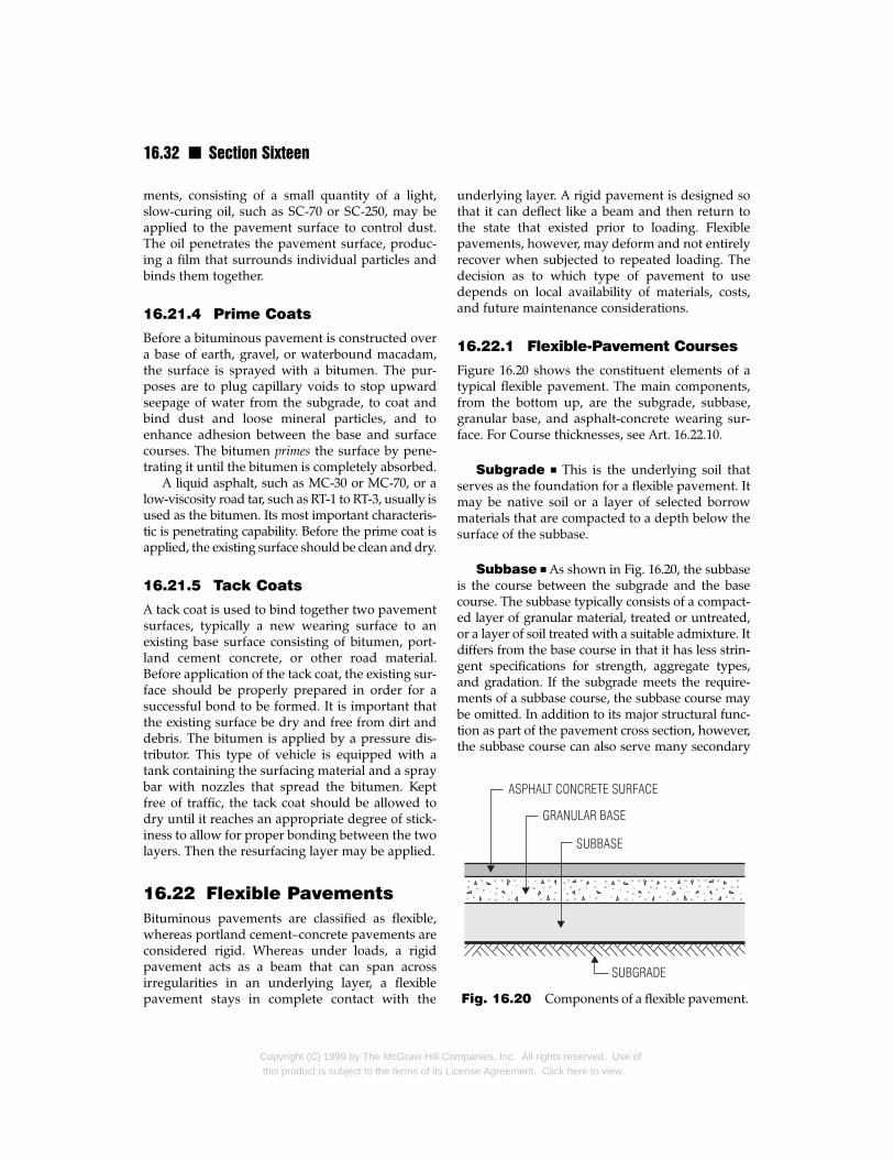
16.32 n Section Sixteen
ments, consisting of a small quantity of a light,slow-curing oil, such as SC-70 or SC-250, may beapplied to the pavement surface to control dust.The oil penetrates the pavement surface, produc-ing a film that surrounds individual particles andbinds them together.
16.21.4 Prime Coats
Before a bituminous pavement is constructed overa base of earth, gravel, or waterbound macadam,the surface is sprayed with a bitumen. The pur-poses are to plug capillary voids to stop upwardseepage of water from the subgrade, to coat andbind dust and loose mineral particles, and toenhance adhesion between the base and surfacecourses. The bitumen primes the surface by pene-trating it until the bitumen is completely absorbed.
A liquid asphalt, such as MC-30 or MC-70, or alow-viscosity road tar, such as RT-1 to RT-3, usually isused as the bitumen. Its most important characteris-tic is penetrating capability. Before the prime coat isapplied, the existing surface should be clean and dry.
16.21.5 Tack Coats
A tack coat is used to bind together two pavementsurfaces, typically a new wearing surface to anexisting base surface consisting of bitumen, port-land cement concrete, or other road material.Before application of the tack coat, the existing sur-face should be properly prepared in order for asuccessful bond to be formed. It is important thatthe existing surface be dry and free from dirt anddebris. The bitumen is applied by a pressure dis-tributor. This type of vehicle is equipped with atank containing the surfacing material and a spraybar with nozzles that spread the bitumen. Keptfree of traffic, the tack coat should be allowed todry until it reaches an appropriate degree of stick-iness to allow for proper bonding between the twolayers. Then the resurfacing layer may be applied.
16.22 Flexible PavementsBituminous pavements are classified as flexible,whereas portland cement–concrete pavements areconsidered rigid. Whereas under loads, a rigidpavement acts as a beam that can span acrossirregularities in an underlying layer, a flexiblepavement stays in complete contact with the
Copyright (C) 1999 by The McGraw-Hill Cothis product is subject to the terms of its Lic
underlying layer. A rigid pavement is designed sothat it can deflect like a beam and then return tothe state that existed prior to loading. Flexiblepavements, however, may deform and not entirelyrecover when subjected to repeated loading. Thedecision as to which type of pavement to usedepends on local availability of materials, costs,and future maintenance considerations.
16.22.1 Flexible-Pavement Courses
Figure 16.20 shows the constituent elements of atypical flexible pavement. The main components,from the bottom up, are the subgrade, subbase,granular base, and asphalt-concrete wearing sur-face. For Course thicknesses, see Art. 16.22.10.
Subgrade n This is the underlying soil thatserves as the foundation for a flexible pavement. Itmay be native soil or a layer of selected borrowmaterials that are compacted to a depth below thesurface of the subbase.
Subbase n As shown in Fig. 16.20, the subbaseis the course between the subgrade and the basecourse. The subbase typically consists of a compact-ed layer of granular material, treated or untreated,or a layer of soil treated with a suitable admixture. Itdiffers from the base course in that it has less strin-gent specifications for strength, aggregate types,and gradation. If the subgrade meets the require-ments of a subbase course, the subbase course maybe omitted. In addition to its major structural func-tion as part of the pavement cross section, however,the subbase course can also serve many secondary
Fig. 16.20 Components of a flexible pavement.
mpanies, Inc. All rights reserved. Use ofense Agreement. Click here to view.
Highway Engineering n 16.33
functions, such as limiting damage due to frost, pre-venting accumulation of free water within or belowthe pavement structure, and preventing intrusionof fine-grain subgrade soils into the base courses. Inrock cuts, the subbase course can also act as a work-ing platform for construction equipment or for sub-sequent pavement courses. Performance of thesesecondary functions depends on the type of mater-ial selected for the subbase course.
Base Course n This is the layer of materialdirectly under the surface course. The base courserests on the subbase or, if no subbase is provided,on the subgrade. A structural portion of the pave-ment, the base course consists of aggregates suchas crushed stone, crushed slag, gravel and sand, ora combination of these.
Specifications for base-course materials aremuch more stringent than those for subbase-course materials. This is especially the case for suchproperties as strength, stability, hardness, aggre-gate types, and gradation. Addition of a stabilizingadmixture, such as portland cement, asphalt, orlime, can improve the characteristics of a widevariety of materials that, if untreated, would beunsuitable for use as a base course. From an eco-nomic standpoint, such treatment is especiallybeneficial when there is a limited supply of suit-able untreated material.
Surface Course n This is the uppermostlayer of material in a flexible pavement. It isdesigned to support anticipated traffic, resist itsabrasive forces, limit the amount of surface waterthat penetrates into the pavement, provide a skid-resistant surface, and offer a smooth riding surface.To serve these purposes, the surface course shouldbe durable, regardless of weather conditions.
Surface courses typically consist of bituminousmaterial and mineral aggregates that are well grad-ed and have a maximum size of about ¾ to 1 in.Various other gradations ranging from sand (usedin sheet asphalt) to coarse, open-graded mixturesof coarse and fine aggregates have been used withsatisfactory results under specific conditions
16.22.2 Flexible-Pavement DesignAssumptions
Flexible pavements are designed as a multilayeredelastic system. Each course of a pavement is a layer
Copyright (C) 1999 by The McGraw-Hill Cothis product is subject to the terms of its Li
with specific material properties that differ fromthose of the other layers and that affect the overallperformance of the pavement. All layers areassumed to be infinite in the horizontal plane. Thesubgrade, the bottom layer, is assumed to be infi-nite in the vertical plane as well.
As the wheel of a vehicle passes over the pave-ment, compressive stresses are imposed in the sur-face course directly under the wheel. The surfacecourse distributes the stresses over the base course,which, in turn, transmits them to the lower cours-es. The stresses are greatest at the top of the surfacecourse and decrease toward the subgrade. Hori-zontal stresses exist below the wheel load also.They vary from compression (above the neutralaxis of the pavement cross section) to tension(below the neutral axis). In addition, the pavementis subjected to thermal stresses.
Flexible pavements usually are designed by amethod promulgated by the American Associa-tion of State Highway and Transportation Offi-cials (AASHTO), or the Asphalt Institute, or theCalifornia Department of Transportation (Cal-trans). Article 16.22.3 presents an overview of theAASHTO method.
16.22.3 AASHTO Design Methodfor Flexible Pavements
The AASHTO “Guide for Design of PavementStructures” takes into account pavement perfor-mance, traffic volume, subgrade soils, constructionmaterials, environment, drainage, reliability, life-cycle costs, and shoulder design. In essence, thedesign procedure is to convert the varying axleloads to a single design load and to express thetraffic volume as the number of repetitions of thedesign axle load (Arts. 16.22.4 to 16.22.10).
16.22.4 Flexible-PavementPerformance
Pavement performance includes both the structur-al and functional performance of the pavementstructure. Structural performance describes theability of the pavement to support traffic loadingwithout excessive permanent deformations, crack-ing, faulting, raveling, etc. Functional performanceaddresses the ability of the pavement to fulfill itsintended functions such as maintaining a smoothand uniform riding surface.
mpanies, Inc. All rights reserved. Use ofcense Agreement. Click here to view.
16.34 n Section Sixteen
Pavement performance is also used to describethe ability of the pavement to provide for the safe-ty of vehicles and their passengers. An importantpavement feature that impacts safety is the frictionbetween vehicle tires and the pavement.
The influence of pavement performance in theAASHTO design method is represented by the pre-
sent serviceability index (PSI), which takes intoaccount pavement roughness and distress as indi-cated by the extent of cracking, patching, and rutdepth present. The PSI is based on a scale from 0 to5; the higher the number the better the condition;that is, the smoother the pavement. A pavementwith a PSI of 4.5, for example, is smoother (lessrough) than a pavement with a PSI of 4.0. Theassumption is that a smooth pavement will have alonger life than a rough one.
Two serviceability indexes are used in design of apavement structure. One is the initial serviceabilityindex pi, which represents the condition of the pave-ment when new. The second is the terminal service-ability index pt, which represents the minimumacceptable roughness at which stage rehabilitation isneeded. AASHTO suggests the following maximumvalues of pt: 2.5 or 3.0 for major highways, 2.0 forlower classifications, and 1.5 for extreme situationsfor low-volume roads where costs must be kept lowand then on a case-by-case basis.
While deterioration and the related loss of ser-viceability of a pavement are related to the age ofthe pavement, volume of traffic, and various envi-ronmental conditions, there is no direct relation-ship that incorporates the combined impact ofthese variables. Therefore, some degree of idealiza-tion is required; for example, age may be taken asa net negative factor that reduces serviceability.
16.22.5 Traffic Loads
The effects of traffic loads are determined by theuse of an equivalent single 18-kip axle load (ESAL).The AASHTO method takes into account axleloads, axle configuration, and number of applica-tions of the loads. The actual loading is related toESAL by equivalence factors based on the terminalserviceability index pt (Art. 16.22.4) and a parame-ter called structural number SN. The structuralnumber is used to describe the overall thickness ofthe pavement (Art. 16.22.10).
Tables 16.6 and 16.7 list axle-load equivalencefactors for single and tandem axles acting on flexi-
Copyright (C) 1999 by The McGraw-Hill Cothis product is subject to the terms of its Lic
ble pavements with a pt of 2.0 and 2.5, respectively.These tables can be used to convert mixed trafficloads to an equivalent number of 18-kip loads.
The accuracy of traffic estimates depends great-ly on the accuracy of the following: load equiva-lence values, estimates of traffic volume andweight, prediction of ESAL over the design period,and interaction of age and traffic as it affectschanges in PSI (Art. 16.22.4).
Traffic predictions are made for a convenientperiod of time, typically 20 years. Any period,however, may be used with the AASHTO designmethod since traffic is expressed as daily or totalESAL applications. The total ESAL applications arethe number of repetitions of the loading that thepavement is expected to carry, from opening of theroad to the time when it reaches its terminal value,for example, when pt = 2.0.
For design purposes, the traffic must be distrib-uted by direction and by lanes. Directional distrib-ution is generally made by assigning 50% of thetraffic to each direction (if special conditions do notwarrant some other distribution). Lane distribu-tion is usually made by assigning 100% of the traf-fic in each direction to each lane. Some states, how-ever, have developed lane distribution percentagesfor highways with more than one lane in a givendirection. Depending on the total number of lanespresent, these percentages typically range from 60to 100% of the one-directional traffic.
Because of the importance of the traffic datadesign of a pavement, the design team shouldwork closely with the personnel involved in thegathering of this information. Poor traffic estimatescan adversely affect highway performance andeconomy.
16.22.6 Subgrade Support forFlexible Pavements
A pavement is designed to distribute traffic loadsto the subgrade, which must be capable of with-standing the resulting stresses. Hence the perfor-mance of the pavement depends greatly on thephysical properties and condition of the subgradesoils. AASHTO characterizes the soil by its resilientmodulus MR, psi. The resilient modulus takes intoaccount various nonlinear properties of the soil.(MR replaces the soil support value S used in thepast. The change was made because of the applic-ability of the resilient modulus to multilayered sys-
mpanies, Inc. All rights reserved. Use ofense Agreement. Click here to view.

Highway Engineering n 16.35
Single Axles
Structural number SN
1 2 3 4 5 6
2 0.0002 0.0002 0.0002 0.0002 0.0002 0.00024 0.002 0.003 0.002 0.002 0.002 0.0026 0.01 0.01 0.01 0.01 0.01 0.018 0.03 0.04 0.04 0.03 0.03 0.03
10 0.08 0.08 0.09 0.08 0.08 0.0812 0.16 0.18 0.19 0.18 0.17 0.1714 0.32 0.34 0.35 0.35 0.34 0.3316 0.59 0.60 0.61 0.61 0.60 0.6018 1.00 1.00 1.00 1.00 1.00 1.0020 1.61 1.59 1.56 1.55 1.57 1.6022 2.49 2.44 2.35 2.31 2.35 2.4124 3.71 3.62 3.43 3.33 3.40 3.5126 5.36 5.21 4.88 4.68 4.77 4.9628 7.54 7.31 6.78 6.42 6.52 6.8330 10.38 10.03 9.24 8.65 8.73 9.1732 14.00 13.51 12.37 11.46 11.48 12.1734 18.55 17.87 16.30 14.97 14.87 15.6336 24.20 23.30 21.16 19.28 19.02 19.9338 31.14 29.95 27.12 24.55 24.03 25.1040 39.57 38.02 34.34 30.92 30.04 31.25
Tandem Axles
Structural number SN
1 2 3 4 5 8
10 0.01 0.01 0.01 0.01 0.01 0.0112 0.01 0.02 0.02 0.01 0.01 0.0114 0.02 0.03 0.03 0.03 0.02 0.0216 0.04 0.05 0.05 0.05 0.04 0.0418 0.07 0.08 0.08 0.08 0.07 0.0720 0.10 0.12 0.12 0.12 0.11 0.1022 0.16 0.17 0.18 0.17 0.16 0.1624 0.23 0.24 0.26 0.25 0.24 0.2326 0.32 0.34 0.36 0.35 0.34 0.3328 0.45 0.46 0.49 0.48 0.47 0.4630 0.61 0.62 0.65 0.64 0.63 0.6232 0.81 0.82 0.84 0.84 0.83 0.8234 1.06 1.07 1.08 1.08 1.08 1.0736 1.38 1.38 1.38 1.38 1.38 1.3838 1.76 1.75 1.73 1.72 1.73 1.7440 2.22 2.19 2.15 2.13 2.16 2.1842 2.77 2.73 2.64 2.62 2.66 2.7044 3.42 3.36 3.23 3.18 3.24 3.3146 4.20 4.11 3.92 3.83 3.91 4.0248 5.10 4.98 4.72 4.58 4.68 4.83
*From “Guide for Design of Pavement Structures,” American Association of State Highway and Transportation Officials.
Table 16.6 Axle-Load Equivalence Factors for Flexible Pavement, pt = 2.0*
Axle-Load,kips
Axle-Load,kips
Copyright (C) 1999 by The McGraw-Hill Companies, Inc. All rights reserved. Use ofthis product is subject to the terms of its License Agreement. Click here to view.

16.36 n Section Sixteen
Single Axles
Structural number SN
1 2 3 4 5 6
2 0.0004 0.0004 0.0003 0.0002 0.0002 0.00024 0.003 0.004 0.004 0.003 0.003 0.0026 0.01 0.02 0.02 0.01 0.01 0.018 0.03 0.05 0.05 0.04 0.03 0.03
10 0.08 0.10 0.12 0.10 0.09 0.0812 0.17 0.20 0.23 0.21 0.19 0.1814 0.33 0.36 0.40 0.39 0.36 0.3416 0.59 0.61 0.65 0.65 0.62 0.6118 1.00 1.00 1.00 1.00 1.00 1.0020 2.61 1.57 1.49 1.47 1.51 1.5522 2.48 2.38 2.17 2.09 2.18 2.3024 3.69 3.49 3.09 2.89 3.03 3.2726 5.33 4.99 4.31 3.91 4.09 4.4828 7.49 6.98 5.90 5.21 5.39 5.9830 10.31 9.55 7.94 6.83 6.97 7.7932 13.90 12.82 10.52 8.85 8.88 9.9534 18.41 16.94 13.74 11.34 11.18 12.5136 24.02 22.04 17.73 14.38 13.93 15.5038 30.90 28.30 22.61 18.06 17.20 18.9840 39.26 35.89 28.51 22.50 21.08 23.04
Tandem Axles
Structural number SN
1 2 3 4 5 6
10 0.01 0.01 0.01 0.01 0.01 0.0112 0.02 0.02 0.02 0.02 0.01 0.0114 0.03 0.04 0.04 0.03 0.03 0.0216 0.04 0.07 0.07 0.06 0.05 0.0418 0.07 0.10 0.11 0.09 0.08 0.0720 0.11 0.14 0.16 0.14 0.12 0.1122 0.16 0.20 0.23 0.21 0.18 0.1724 0.23 0.27 0.31 0.29 0.26 0.2426 0.33 0.37 0.42 0.40 0.36 0.3428 0.45 0.49 0.55 0.53 0.50 0.4730 0.61 0.65 0.70 0.70 0.66 0.6332 0.81 0.84 0.89 0.89 0.86 0.8334 1.06 1.08 1.11 1.11 1.09 1.0836 1.38 1.38 1.38 1.38 1.38 1.3838 1.75 1.73 1.69 1.68 1.70 1.7340 2.21 2.16 2.06 2.03 2.08 2.1442 2.76 2.67 2.49 2.43 2.51 2.6144 3.41 3.27 2.99 2.88 3.00 3.1646 4.18 3.98 3.58 3.40 3.55 3.7948 5.08 4.80 4.25 3.98 4.17 4.49
*From “Guide for Design of Pavement Structures,” American Association of State Highway and Transportation Officials.
Table 16.7 Axle-Load Equivalence Factors for Flexible Pavement, pt = 2.5*
Axle-Load,kips
Axle-Load,kips
Copyright (C) 1999 by The McGraw-Hill Companies, Inc. All rights reserved. Use ofthis product is subject to the terms of its License Agreement. Click here to view.
Highway Engineering n 16.37
tems in general and pavement structures in partic-ular.) Because some transportation agencies do nothave the ability to perform the resilient modulustest (described in AASHTO Test Method T274), theAASHTO “Guide for Design of Pavement Struc-tures” contains correlations that relate the fre-quently used California bearing ratios (CBR) andstabilometer R values to an equivalent MR.
An equivalent MR can be determined for theCorps of Engineers CBR value from
(16.17)
Equation (16.17) is valid for fine-grain soils with asoaked CBR of 10 or less. An equivalent value MRbased on an R value can be determined for fine-grain soils with an R value less than or equal to 20from
(16.18)
The AASHTO “Guide” contains design curves forconversion to a structural number SN (Art. 16.22.9).
The resilient modulus is based on the proper-ties of the compacted subgrade soils. It may be nec-essary, however, to include the properties of in situmaterials in the uncompacted foundation if thesematerials are especially weak. Also, compaction ofthe subgrade is essential to ensure adequate per-formance and reliability.
16.22.7 Flexible-Pavement Material
For flexible pavements, materials used for subbase,base, and surface courses differ. Article 16.22.1describes the properties and characteristics ofthese layers. For more detailed information, seeAASHTO “Guide for the Design of PavementStructures” and “Construction Manual for High-way Construction.”
In addition to the aforementioned three princi-pal layers, the prepared roadbed is an importantcomponent of a flexible pavement, and a drainagelayer also may be necessary. The prepared roadbedmay be a layer of compacted roadbed soil or selectborrow material that is compacted to a specifieddensity. Examples of a drainage layer are given inFig. 16.21. Figure 16.21a shows a base course thatserves also as a drainage layer, whereas Fig. 16.21bshows a drainage layer between the subbase andthe subgrade.
Copyright (C) 1999 by The McGraw-Hill Cothis product is subject to the terms of its Li
16.22.8 Flexible-PavementDrainage
Rainfall is one of the principal environmental con-ditions that affects the design and performance ofpavements. The major concern with rainwater isthat it may penetrate through the pavement intothe roadbed soil and weaken it. Proper drainage isan important element in preventing this. Experi-ence has shown that pavements that are not prop-erly drained deteriorate prematurely, especiallywhen exposed to heavy traffic volumes and theirrelated loads.
Articles 16.16 and 16.17 discuss the adverseeffects when water penetrates a pavement anddescribes some methods employed to prevent thisand to remove water from the surface of the road-way. The AASHTO design method for flexible pave-ments takes into account the impact of swelling,frost heave, and moisture on roadbed soil and basestrength. This is done by multiplying the structurallayer coefficients a1 and a2 (Art. 16.22.9) by a factor mithat takes into account the quality of drainage andthe percent of time the pavement is subjected tomoisture levels approaching saturation. The qualityof drainage is indicated by the amount of time need-ed to drain the base layer to 50% of saturation.
(“Guide for Design of Pavement Structures,”American Association of State Highway and Trans-portation Officials.)
16.22.9 Structural Numbers forFlexible Pavements
The design of a flexible pavement or surface treat-ment expected to carry more than 50,000 repeti-tions of ESAL (Art. 16.22.5) requires identificationof a structural number SN that is used as a measureof the ability of the pavement to withstand antici-pated axle loads. In the AASHTO design method,the structural number is defined by
(16.19)
where SN1 = structural number for the surfacecourse = a1D1
a1 = layer coefficient for the surfacecourse
D1 = actual thickness of the surfacecourse, in
mpanies, Inc. All rights reserved. Use ofcense Agreement. Click here to view.
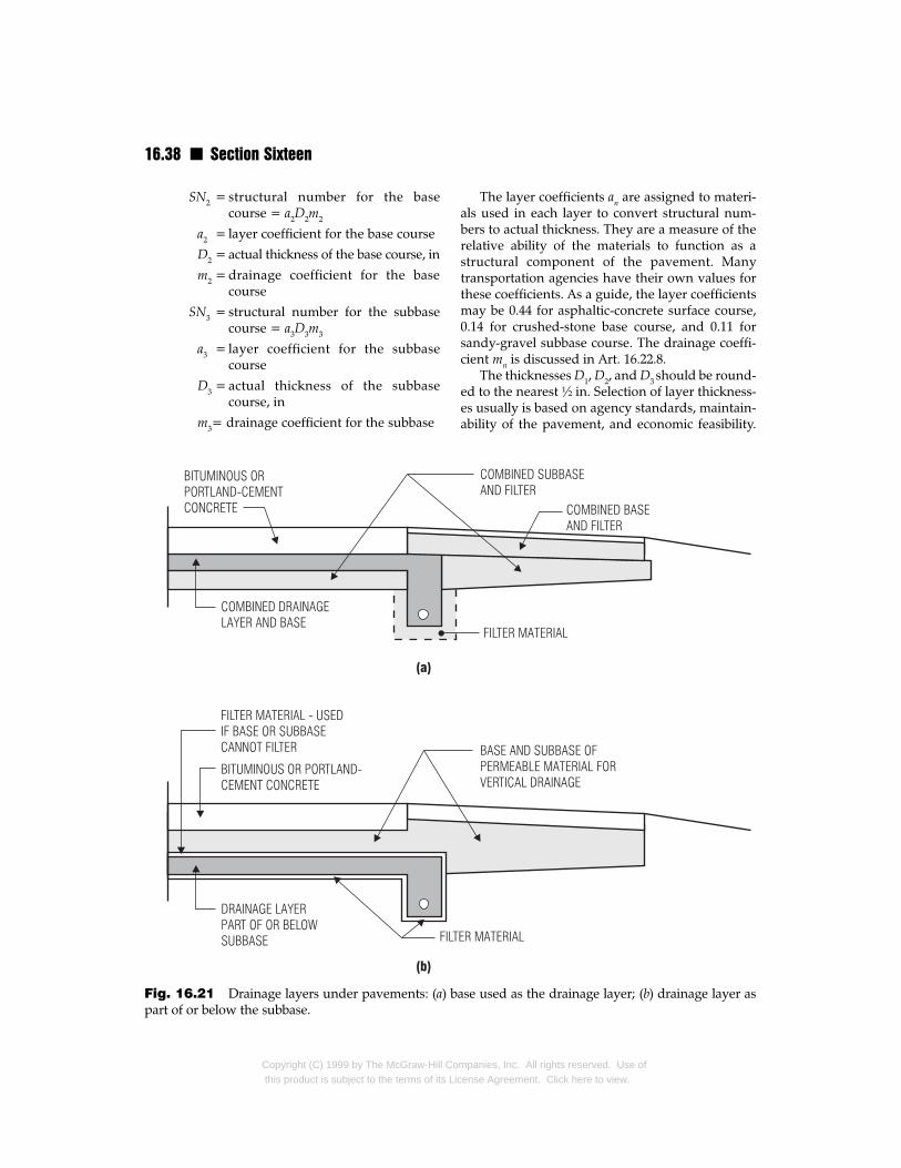
16.38 n Section Sixteen
SN2 = structural number for the basecourse = a2D2m2
a2 = layer coefficient for the base course
D2 = actual thickness of the base course, in
m2 = drainage coefficient for the basecourse
SN3 = structural number for the subbasecourse = a3D3m3
a3 = layer coefficient for the subbasecourse
D3 = actual thickness of the subbasecourse, in
m3= drainage coefficient for the subbase
Fig. 16.21 Drainage layers under pavements: (a) bapart of or below the subbase.
Copyright (C) 1999 by The McGraw-Hill Cothis product is subject to the terms of its Lic
The layer coefficients an are assigned to materi-als used in each layer to convert structural num-bers to actual thickness. They are a measure of therelative ability of the materials to function as astructural component of the pavement. Manytransportation agencies have their own values forthese coefficients. As a guide, the layer coefficientsmay be 0.44 for asphaltic-concrete surface course,0.14 for crushed-stone base course, and 0.11 forsandy-gravel subbase course. The drainage coeffi-cient mn is discussed in Art. 16.22.8.
The thicknesses D1, D2, and D3 should be round-ed to the nearest ½ in. Selection of layer thickness-es usually is based on agency standards, maintain-ability of the pavement, and economic feasibility.
se used as the drainage layer; (b) drainage layer as
mpanies, Inc. All rights reserved. Use ofense Agreement. Click here to view.
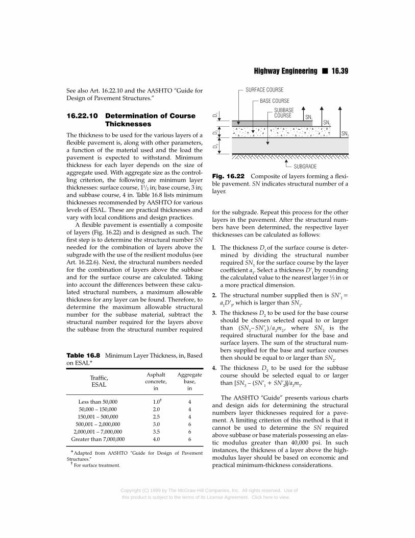
Highway Engineering n 16.39
See also Art. 16.22.10 and the AASHTO “Guide forDesign of Pavement Structures.”
16.22.10 Determination of CourseThicknesses
The thickness to be used for the various layers of aflexible pavement is, along with other parameters,a function of the material used and the load thepavement is expected to withstand. Minimumthickness for each layer depends on the size ofaggregate used. With aggregate size as the control-ling criterion, the following are minimum layerthicknesses: surface course, 11/2 in; base course, 3 in;and subbase course, 4 in. Table 16.8 lists minimumthicknesses recommended by AASHTO for variouslevels of ESAL. These are practical thicknesses andvary with local conditions and design practices.
A flexible pavement is essentially a compositeof layers (Fig. 16.22) and is designed as such. Thefirst step is to determine the structural number SNneeded for the combination of layers above thesubgrade with the use of the resilient modulus (seeArt. 16.22.6). Next, the structural numbers neededfor the combination of layers above the subbaseand for the surface course are calculated. Takinginto account the differences between these calcu-lated structural numbers, a maximum allowablethickness for any layer can be found. Therefore, todetermine the maximum allowable structuralnumber for the subbase material, subtract thestructural number required for the layers abovethe subbase from the structural number required
Asphalt Aggregateconcrete, base,
in in
Less than 50,000 1.0† 450,000 – 150,000 2.0 4150,001 – 500,000 2.5 4
500,001 – 2,000,000 3.0 62,000,001 – 7,000,000 3.5 6
Greater than 7,000,000 4.0 6
*Adapted from AASHTO “Guide for Design of PavementStructures.”
† For surface treatment.
Table 16.8 Minimum Layer Thickness, in, Basedon ESAL*
Traffic,ESAL
Copyright (C) 1999 by The McGraw-Hill Cothis product is subject to the terms of its Li
for the subgrade. Repeat this process for the otherlayers in the pavement. After the structural num-bers have been determined, the respective layerthicknesses can be calculated as follows:
l. The thickness D1 of the surface course is deter-mined by dividing the structural numberrequired SN1 for the surface course by the layercoefficient a1. Select a thickness D′1 by roundingthe calculated value to the nearest larger ½ in ora more practical dimension.
2. The structural number supplied then is SN′1 =a1D′1, which is larger than SN1.
3. The thickness D2 to be used for the base courseshould be chosen selected equal to or largerthan (SN2– SN′1 ) /a2m2 , where SN2 is therequired structural number for the base andsurface layers. The sum of the structural num-bers supplied for the base and surface coursesthen should be equal to or larger than SN2.
4. The thickness D3 to be used for the subbasecourse should be selected equal to or largerthan [SN3 – (SN′1 + SN′2)]/a3m3.
The AASHTO “Guide” presents various chartsand design aids for determining the structuralnumbers layer thicknesses required for a pave-ment. A limiting criterion of this method is that itcannot be used to determine the SN requiredabove subbase or base materials possessing an elas-tic modulus greater than 40,000 psi. In suchinstances, the thickness of a layer above the high-modulus layer should be based on economic andpractical minimum-thickness considerations.
Fig. 16.22 Composite of layers forming a flexi-ble pavement. SN indicates structural number of alayer.
mpanies, Inc. All rights reserved. Use ofcense Agreement. Click here to view.
16.40 n Section Sixteen
See also “Thickness Design—Full DepthAsphalt Pavement Structures for Highways andStreets,” Manual MS-1, The Asphalt Institute, Col-lege Park, MD 10740.
16.23 Alternative FlexiblePavements
A variety of technologies are available as alterna-tives to the type discussed in Art. 16.22. Included inthis category are porous pavements, sulfur-asphaltmixes, hydrated-lime additives, rubberized wear-ing surfaces, recycled asphalt pavements, and theSuperpave mix design system.
16.23.1 Porous Pavements
These are essentially asphalt pavements withoutany fines (sand) in the mix. This type of pavementcontains voids through which rainwater is allowedto seep into the subgrade. This characteristic offersseveral advantages: Removal of water from thepavement decreases the possibility of damagefrom trapped water, thus increasing pavement life.Also, if storm water from the pavement can perco-late into the soil, a smaller highway drainage sys-tem is needed. If there is an existing storm sewer,the risk of overloading it is also greatly reduced.Furthermore, porous pavements enhance trafficsafety by decreasing the risk of hydroplaning (wetskidding). In addition, driver visibility of pave-ment markings does not suffer in rain because thewater percolates rapidly through the porousasphalt surface. From an aesthetic viewpoint,porous pavement is not objectionable since there isno basic visual difference between porous andconventional, nonpermeable pavements.
Porous pavements are generally used in high-ways, local streets, and parking lots. For parkinglots, porous pavements are advantageous becauserain seeping from them into the subgrade pro-motes healthy growth of trees, shrubs, groundcover, and other plantings and thus makes a park-ing area and associated landscaping more aesthet-ically pleasing. For a parking area, a typical porouspavement consists of a 21/2-in surface course ofporous bituminous concrete over a 12-in graded,crushed-stone base. The base course is layered.Small stones form the top layer so that a pavingmachine can create a smooth surface for applica-tion of the surface course.
Copyright (C) 1999 by The McGraw-Hill Cothis product is subject to the terms of its Lic
16.23.2 Sulfur-Asphalt Mixes
Sulfur is used in bituminous pavements in severalways. In one method, sulfur serves as a filler. It isadded to a hot sand-asphalt mix after the asphaltand aggregate have been mixed. The sulfur fills thevoids and locks the sand particles, stabilizing themix. In another method, sulfur and asphalt areblended to form sulfur-extended asphalt (SEA).The hot sulfur is dispersed into the asphalt to cre-ate a binder that is then mixed with the aggregate.Production of SEA requires only a slight modifica-tion of the hot-mix plant. Otherwise, the construc-tion operations and equipment for SEA are thesame as that for asphalt concrete.
Sulfur is also used for roads in areas subject topermafrost. Conventional highway constructionpractice calls for gravel depths of 5 ft or morebelow the ground surface to provide a stable load-bearing surface. Also, thermal insulation isinstalled below the gravel to protect the underly-ing permafrost. When gravel is not available local-ly, as is often the case in many northern areas, itmust be transported to the project site from else-where at considerable expense. Construction costscan be cut, however, by reducing significantly theamount of gravel required through use of sulfur infoam form with gravel. One test showed that 7 ft ofgravel could be replaced by only 3 ft of gravel setatop 3 to 4 in of sulfur foam.
There are, however, health hazards associatedwith the use of sulfur in general. For instance, nox-ious gases, such as sulfur dioxide and hydrogendisulfide, can be generated at the plant and theconstruction site.
16.23.3 Hydrated Lime
This is widely used in hot mixes that contain mar-ginally acceptable aggregates. The lime acts as achemical additive rather than a void filler. Itincreases the strength and stability of an asphaltmix while making it more water resistant. Also byhardening mixes, it allows faster compaction andyields higher densities.
16.23.4 Rubber in Wearing Courses
Rubber is used to improve the paving qualities ofhot mixes used in bituminous wearing courses. Forthis purpose, rubber may be added to an asphalt-concrete mix or applied to the pavement surface
mpanies, Inc. All rights reserved. Use ofense Agreement. Click here to view.
Highway Engineering n 16.41
after placement and compaction. The rubberreduces temperature susceptibility, decreases rav-eling, offers better void control, and lessens thetendency to flow, improving flexibility and adhe-sion to aggregates.
16.23.5 Superpave Mix DesignSystem
Developed by the Strategic Highway ResearchProgram (SHRP), the Superpave mix design sys-tem is a method of designing flexible-pavementmixes that are tailored to specific project character-istics. These include traffic, environment, pave-ment structural section, and reliability.
The Superpave mix design system assists inselection of combinations of asphalt binder,aggregate, and any necessary modifiers to obtaina desired level of pavement performance. Thegoal of the system is to create an ideal blend ofasphalt binder and aggregate for production ofthe lowest-cost pavement for the anticipated levelof service.
The Superpave system applies to three differ-ent levels of traffic, low, intermediate, and high,and employs laboratory and field testing tech-niques. Computer software based on the Super-pave specifications is available to assist in theprocess. The software and associated specifica-tions perform analysis and design of multiplelayer pavements consisting of base, binder, andsurface courses. For example, selection of the nec-essary materials used in the Superpave mix isbased on, among other things, the design ESALfor the project (Art. 16.22.5). ESALs are used toascertain whether the anticipated traffic level islow, intermediate, or high. Also taken into accountare pavement environmental conditions influ-enced by climate. Based on these conditions, anasphalt binder, for example, can be chosen.
The Superpave system also allows for additionof modifiers, such as fibers or hydrated lime, to themix to enhance the ability of the paving mixes toavoid pavement distresses. While the system doesnot offer a list of modifiers for correction of specif-ic pavement distress, it does offer a guide based onAASHTO Practice PP5, “The Laboratory Evalua-tion of Modified Asphalt Systems,” to assist in theselection of appropriate modifiers to enhance theperformance of the pavement.
(“The Superpave Mix Design Manual for New
Copyright (C) 1999 by The McGraw-Hill Cothis product is subject to the terms of its Li
Construction and Overlays,” SHRP-A-407, Strate-gic Highway Research Program, National ResearchCouncil, 2101 Constitution Ave., NW, Washington,DC 20418.)
16.23.6 Recycling of AsphaltPavements
The materials in an asphalt pavement that is sched-uled for replacement can be reused as ingredients ofa new surface course or a new pavement, includingunderlying, untreated base material. The recyclingmay be performed in place or at a central plant.
When the asphalt pavement is to be recycled atthe site, a process known as in-place, cold-mix,asphalt-pavement recycling is used. In thisprocess, the existing pavement materials areripped, broken, pulverized, and mixed in placewith asphalt or other materials, such as aggregatesor stabilizing agents. The other materials usuallyare required to provide a higher-strength base. Theprocess requires that an asphalt surface course beplaced on top of the recycled layer. One drawbackto this process is that quality control is not so goodin the field as it would be at a central plant. Anoth-er is that maintenance of traffic is difficult becauseof the necessity of avoiding interference with therecycling equipment. The cold-mix process, how-ever, can also be conducted at a central plantwhere enhanced quality control provides highermix efficiency and reliability. Central plants alsooffer higher production capacity and better unifor-mity and reliability.
An alternative to the cold-mix process is hot-mix, asphalt-pavement recycling, which is per-formed at a central plant. In this process, reclaimedasphalt-pavement materials are removed from anexisting roadway in a fashion similar to thatdescribed for the cold-mix process and combinedin the central plant with new asphalt or recycledagents. The hot-mix method also sometime utilizesuncoated aggregates from the base to produce thehot mix. For the hot-mix recycling process, one ofthe following types of plants is generally used:batch, drum mixer, or continuous mixer.
Several factors affect the feasibility of a recy-cling project. These include availability of recyclingequipment, impact on traffic through the construc-tion site, and the size and location of the project. Inthe right situation, however, recycling can offermany economic and environmental advantages.
mpanies, Inc. All rights reserved. Use ofcense Agreement. Click here to view.
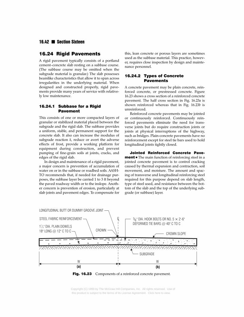
16.42 n Section Sixteen
16.24 Rigid PavementsA rigid pavement typically consists of a portlandcement–concrete slab resting on a subbase course.(The subbase course may be omitted when thesubgrade material is granular.) The slab possessesbeamlike characteristics that allow it to span acrossirregularities in the underlying material. Whendesigned and constructed properly, rigid pave-ments provide many years of service with relative-ly low maintenance.
16.24.1 Subbase for a RigidPavement
This consists of one or more compacted layers ofgranular or stabilized material placed between thesubgrade and the rigid slab. The subbase providesa uniform, stable, and permanent support for theconcrete slab. It also can increase the modulus ofsubgrade reaction k, reduce or avert the adverseeffects of frost, provide a working platform forequipment during construction, and preventpumping of fine-grain soils at joints, cracks, andedges of the rigid slab.
In design and maintenance of a rigid pavement,a major concern is prevention of accumulation ofwater on or in the subbase or roadbed soils. AASH-TO recommends that, if needed for drainage pur-poses, the subbase layer be carried 1 to 3 ft beyondthe paved roadway width or to the inslope. Anoth-er concern is prevention of erosion, particularly atslab joints and pavement edges. To compensate for
Fig. 16.23 Components of a r
Copyright (C) 1999 by The McGraw-Hill Cothis product is subject to the terms of its Lic
this, lean concrete or porous layers are sometimesused as the subbase material. This practice, howev-er, requires close inspection by design and mainte-nance personnel.
16.24.2 Types of ConcretePavements
A concrete pavement may be plain concrete, rein-forced concrete, or prestressed concrete. Figure16.23 shows a cross section of a reinforced concretepavement. The half cross section in Fig. 16.23a isshown reinforced whereas that in Fig. 16.23b isunreinforced.
Reinforced concrete pavements may be jointedor continuously reinforced. Continuously rein-forced pavements eliminate the need for trans-verse joints but do require construction joints orjoints at physical interruptions of the highway,such as bridges. Plain-concrete pavements have noreinforcement except for steel tie bars used to holdlongitudinal joints tightly closed.
Jointed Reinforced Concrete Pave-ment n The main function of reinforcing steel in ajointed concrete pavement is to control crackingcaused by thermal expansion and contraction, soilmovement, and moisture. The amount and spac-ing of transverse and longitudinal reinforcing steelrequired for this purpose depend on slab length,type of steel used, and resistance between the bot-tom of the slab and the top of the underlying sub-grade (or subbase) layer.
einforced concrete pavement.
mpanies, Inc. All rights reserved. Use ofense Agreement. Click here to view.
Highway Engineering n 16.43
Continuously Reinforced ConcretePavement n The principal reinforcement in acontinuously reinforced pavement is longitudinalsteel, which may be reinforcing bars or deformedwire fabric. It is used to control cracking caused byvolume changes in the concrete.
In addition to the longitudinal steel, transversereinforcement may be provided to control thewidth of longitudinal cracks. When longitudinalcracking is not expected to be troublesome, trans-verse reinforcement may not be required.
Design of continuously reinforced pavementsshould take into account the properties of the con-crete used. Specifically, the concrete properties thataffect the design of continuously reinforced pave-ments are tensile strength, shrinkage characteris-tics, and thermal coefficient. Pavement designshould also take into account the anticipated dropin temperature, which for design purposes is thedifference between the average concrete curingtemperature and a design minimum temperature.
Longitudinal reinforcing steel used typicallyconsists of No. 5 and No. 6 deformed bars. Whenwire fabric is used, the diameter should be of suffi-cient size that corrosion and deterioration will notsignificantly impair the cross-sectional propertiesof the fabric.
16.24.3 Reinforced ConcretePavement Slabs
These are typically constructed of portlandcement–concrete, reinforcing steel, load-transferdevices, and joint sealing materials. These materi-als should conform to the appropriate AASHTO oragency specifications to ensure that pavement dis-tortion or disintegration is minimized.
The thickness of concrete pavement slabs gen-erally is determined with the use of design chartsor computer software. For details of a designmethod, see “Guide for Design of Pavement Struc-tures,” American Association of State Highway andTransportation Officials (AASHTO). In thismethod, the effects of traffic loads are determinedby the use of an equivalent single 18-kip axle load(ESAL). See Arts. 16.22.4 and 16.22.5.
Concrete pavement slabs may be subject to sur-face deterioration caused by deicing agents orexpansion and contraction due to temperaturechanges. To combat such forms of deterioration, air-entrained concrete is used. Air entrainment also
Copyright (C) 1999 by The McGraw-Hill Cothis product is subject to the terms of its Li
improves the workability of the concrete mix. Thedesign of the mix and its material specificationsshould be in accordance with the AASHTO “GuideSpecifications for Highway Construction” andAASHTO “Standard Specifications for Transporta-tion Materials.” Specifications for portland cementconcrete are also promulgated by ASTM. The AASH-TO and ASTM specifications contain requirementsfor the properties of the cement, coarse aggregates,and fine aggregates to be used in the mix.
16.24.4 Reinforcing Steel forConcrete Pavement
The purpose of reinforcing steel in a concrete pave-ment slab is to control cracking as well as tie togeth-er slab segments and act as a load-transfer mecha-nism at joints. The reinforcing steel, whether barsor wire fabric, is generally deformed; that is, thesteel surfaces have a ribbed deformation thatenhances bond between steel and concrete.
The reinforcing steel that is used primarily tocontrol cracking is known as temperature steel.The steel used to tie two slabs together is known astie bars. The steel bars that act as a load-transfermechanism are called dowels.
Temperature steel may consist of deformedbars, a bar mat, or a wire mesh. The purpose oftemperature steel is to control the width of cracks,not necessarily to prevent cracking. If a smoothwire mesh is used, the bond between steel andconcrete is developed through the welded crosswires. When a deformed wire fabric is used, thebond is developed through the deformations onthe steel and at the welded intersections. The steelmesh should be given adequate concrete cover ontop, usually about 3 in. The amount of steel to beprovided depends on slab thickness, length, andmaterial properties, such as type of concrete andreinforcing steel used.
16.24.5 Tie Bars
These are installed between abutting slabs to tiethem together. For this purpose, the tie bars, whichmay be connectors or deformed bars, should havesufficient tensile strength to prevent the slabs fromseparating. (Tie bars are not intended to serve asload-transfer devices.) The tendency for the slabsto separate arises because they try to shorten whenthe temperature drops or moisture content of the
mpanies, Inc. All rights reserved. Use ofcense Agreement. Click here to view.
16.44 n Section Sixteen
concrete decreases (as is the case when the con-crete cures). The resistance to movement providedby the tie bars induces tensile stresses in the con-crete, which must have sufficient tensile strengthto withstand these stresses, or reinforcing steelshould be provided for this purpose. To facilitatebonding, the tie bars are usually equipped with ahook. It is often advantageous to provide the barswith a protective coating, especially when thepavement slab is exposed to deicing agents.
16.24.6 Load-Transfer Devices
Load-transfer devices are installed between theends of abutting slabs to transfer traffic loads fromone to the other yet offer little or no resistance tolongitudinal movements of the slabs. The mostcommon form of load-transfer device is a large-diameter dowel. Other mechanical devices, how-ever, have been used successfully. It is also possibleto achieve load transfer with the interlocking ofaggregate alone.
A dowel provides flexural, shear, and bearingresistance. One end of the dowel is bonded to theconcrete. The other end is allowed to move freely. Forthis purpose, half the dowel adjoining this end maybe greased, painted, or coated with asphalt, thus pre-venting the dowel from bonding to the concrete. Asa result, the dowel can slide freely in the concreteafter embedment in the end of a slab. To ensure prop-er movement of the dowels, it is essential to maintainalignment between the abutting slabs.
Although offering little restraint to longitudinalmovement of the slabs, load-transfer devices shouldalso be mechanically stable under wheel loads andcyclical loading. It is often beneficial to provide thedowel, or other device, with a protective coatingwhen the slab may be exposed to corrosive elements.
Dowel size depends on slab thickness andother site-specific criteria. A general rule of thumbis that the dowel diameter should be equal to one-eighth the slab thickness; for example, for a 9-inslab, a diameter of 11/8 in might be used. Dowelspacing is generally 12 in and dowel length 18 in.
16.24.7 Joints in ConcretePavement
Joints are formed in concrete pavement to reducethe effects of expansion and contraction, facilitateconcrete placement, and allow for bonding of abut-
Copyright (C) 1999 by The McGraw-Hill Cothis product is subject to the terms of its Lic
ting slabs. Joints may be perpendicular to the pave-ment centerline (transverse) and, depending on theintended function of the joints, longitudinal.
Transverse Expansion Joints n The prin-cipal function of an expansion joint in concrete pave-ment is to allow movement of the slab due tochanges in temperature. For example, when temper-ature increases, a slab increases in length, therebycreating compressive stresses in the concrete. Ifexpansion joints are not provided, the slab, depend-ing on its length, might buckle upward or blow up.
In concrete pavement, expansion joints aregenerally placed every 40 to 60 ft along the lengthof the pavement. The joints, which may range inthickness from ¾ to 1 in, should incorporateappropriate load-transfer devices (Art. 16.22.6).Fillers, such as rubber, bitumen, or cork, that per-mit expansion of the slab and exclude dirt shouldbe placed in the joints.
Some transportation agencies specify expan-sion joints, but others do not and instead employalternate methods to minimize the potential forblowups. One way this is done is to use cementand aggregates with properties that limit theamount that slabs increase in length with increasesin temperature.
Transverse Contraction Joints n Con-traction joints are provided to limit the effects oftensile forces in a concrete slab caused by a drop intemperature. The objective is to weaken the slab sothat if the tensile forces are large enough to crackit, the cracks will form at the joints. The depth ofcontraction joints generally is only one-quarter thethickness of the slab. When properly designed andspaced, however, they can also minimize crackingof the slab outside the joints.
Contraction joints can be formed by sawinginto the hardened concrete, by inserting plasticinserts at joint locations before concrete is cast, orby tooling the concrete after placement but beforethe concrete has fully hardened. When aggregateinterlocking is insufficient for transferring loadbetween the pavement sections on either side of ajoint, an appropriate load-transfer mechanismshould be incorporated in the joint.
Longitudinal Joints n These are formedparallel to the highway centerline to facilitate laneconstruction and prevent propagation of irregular,
mpanies, Inc. All rights reserved. Use ofense Agreement. Click here to view.
Highway Engineering n 16.45
longitudinal cracks. The joints can be keyed,butted, mechanically formed, or saw grooved. Toprevent adjacent lanes from separating or faulting,steel tie bars or connections should be embeddedin the concrete, perpendicular to the joints.
Longitudinal joints are formed or sawed to aminimum depth of one-fourth the slab thickness.The maximum longitudinal joint spacing recom-mended by AASHTO is 16 ft.
Construction Joints n When concreteplacement for a concrete slab is interrupted, a con-struction joint is desirable at the cold joint betweenthe two slab sections. In preparation for the inter-ruption, a vertical face is formed with a headerboard at the end of the slab being cast. The headerboard is equipped with a protrusion that, whenformed into the concrete, creates a key way forload transfer between the adjoining slab sections.It is also sometimes desirable to use deformed tiebars to hold the joint closed.
Joint Sealing n Many highway agenciesspecify that all joints be cleaned and also sealed toexclude dirt and water. Others seal only expansionjoints. The basic types of sealants used are liquidseals, preformed elastomeric seals, and cork expan-sion-joint filler.
Liquid seals are poured into a joint where theyare allowed to set. Types of liquid seals usedinclude asphalt, hot-poured rubber, elastomericcompounds, silicone, and polymers.
Preformed elastomeric seals consists of extrud-ed neoprene strips with internal webs that exert anoutward force against the faces of the joint. Thetype of elastomeric seal to specify depends on theanticipated slab movement at the joint. The sealsare provided with a coat of adhesive to fasten themto the faces of the joint.
Highway Intersections andInterchangesAn intersection is the junction or crossing of two ormore roads at the same or different elevations.When the roads are at the same level, the intersec-tion is called an at-grade intersection. When theroads are at different elevations, the intersection isreferred to as a grade separation when there is noconnection between the intersecting roads or as an
Copyright (C) 1999 by The McGraw-Hill Cothis product is subject to the terms of its Li
interchange when connecting roads, such asramps or turning roadways, permit movement ofvehicles between the intersecting roads.
Intersections should be kept simple so that nec-essary movements are obvious to drivers. Unifor-mity of intersections is important to avoid driverconfusion. Factors to be considered for this pur-pose include design speed, intersection angles (90°is preferred), intersection curves, vehicle turningpaths, roadway widths, and traffic control devices.
16.25 At-Grade IntersectionsThe junction or crossing of two or more highwaysat a point of common elevation is called an at-grade intersection.
Intersections of highways and railways at gradeshould be provided with protective and warningdevices. Sight distance is an important design con-sideration when only advance warning of approach-ing trains and railway crossbuck signs are installed.
16.25.1 Geometric Design ofAt-Grade Intersections
Major influences on the geometric design of at-grade intersections include human factors, trafficconsiderations, physical elements, and economicfactors. The goal is to reduce or eliminate the poten-tial for accidents involving vehicular, bicycle, orpedestrian traffic through the intersection. Also, nat-ural transitional paths for traffic must be provided.
Human Factors n Design of an intersectionis affected by human factors, such as drivinghabits, the ability of drivers to make decisions, ade-quate advance warning to drivers regarding thepresence of an intersection, driver decision andreaction time, and the presence of pedestrians atthe intersection.
Traffic Considerations n Traffic volumeand movement impact the design of an at-gradeintersection. Both the design and actual capacity ofthe intersecting highways should be taken intoaccount. Also of concern are the design-hour turn-ing movement and other movements, such asdiverging, merging, weaving, and crossing.
Other traffic criteria include vehicle size, speedand operating characteristics, transit involvement,and, if applicable, the history of accidents at the site.
mpanies, Inc. All rights reserved. Use ofcense Agreement. Click here to view.
16.46 n Section Sixteen
Storage requirements for traffic-signal-controlledapproaches should also be taken into account.
Physical Elements n Geometric and site-specific features whether natural such as topogra-phy and vegetation, or man-made, such as signs,have important influences on design of at-gradeintersections. The horizontal and vertical alignmentof the intersecting roadways also greatly affects thedesign. Both of these elements impact sight dis-tance and angle of intersection. Other featuresaffecting the design are traffic control devices,lighting equipment, and safety appurtenances.
Preexisting site conditions, including abuttingproperty uses, such as shopping areas and indus-trial complexes, and the presence of sidewalks andtheir associated pedestrian traffic, should also befactored into the design process.
Economic Factors n Design of an at-gradeintersection should be both practicable and econom-ically feasible. The cost of required improvementsalong with the impact on abutting residential orcommercial properties should be taken into account.
16.25.2 Types of At-GradeIntersections
Each highway that radiates from an intersectionand forms part of it is known as an intersection
leg. The intersection of two highways generallyresults in four legs. Intersections with more thanfour legs are not recommended.
Three-Leg Intersections n A three-legintersection is formed when one highway starts orterminates at a junction with another highway(Fig. 16.24). Unchannelized T intersections (Fig.16.24a) are usually employed at the intersection ofminor roads with more important highways at anangle not exceeding 30° from the normal. At times,a right-turn lane is provided on one side of thethrough highway (Fig. 16 24b) This type of turnlane is used when right-turning traffic from thethrough highway is significant and left-turningtraffic from the through highway is minor.
Four-Leg Intersections n A four-leg inter-section is formed when two highways cross at grade(Fig. 16.25). The design of four-leg intersections fol-
Copyright (C) 1999 by The McGraw-Hill Cothis product is subject to the terms of its Lic
lows many of the general guidelines for three-legintersections. As with T intersections, the roadwayintersection angle typically should not be more than30° from the normal. Figure 16.25c shows a four-legintersection of a through highway and a minorhighway. The through highway is flared to provideadditional capacity for through and turning move-ments. The flaring is provided through incorpora-tion of parallel auxiliary lanes that are required formajor highways requiring an uninterrupted flowcapacity. Flaring may also be needed where crosstraffic is sufficiently high to warrant signal control.
Channelization at Intersections n This isa method of creating defined paths for vehicle trav-el by installing traffic islands or pavement markingsat at-grade intersections. These defined paths providefor the safe and orderly movement of both vehiclesand pedestrians through the intersections. Chan-nelized intersections are illustrated in Figs. 16.24and 16.25.
Channelization should be used prudently; exces-sive use of channelization may worsen rather thanimprove conditions at an intersection. When prop-erly implemented, channelization can dramaticallyreduce accidents at at-grade intersections. Factorsthat influence design of a channelized intersectioninclude type of design vehicle, vehicle speed, crosssections of roadways, anticipated volumes of vehicleand pedestrian traffic, locations of bus stops, andtype and location of traffic-control devices.
Figure 16.24c and d shows examples of channel-ization of three-leg intersections. In these intersec-tions, the return radius between the intersectingroadways is larger than that used for the unchan-nelized intersections in Fig. 16.24a and b. This isdone to provide space for the channelizing trafficislands. Whether the approach roadway shouldhave a turning lane for right-turning trafficdepends on the volume of traffic that will makeright turns. When speeds or turning paths areabove a prescribed minimum, the incorporation ofdual right-turning roadways, as shown in Fig.16.24d, may be required.
Channelization of four-leg intersections is oftenincorporated for many of the reasons given abovefor three-leg intersections. In Fig. 16.25b, a four-legintersection with right-turning lanes in all fourquadrants is shown. This approach is taken whenspace is readily available and turning movementsare critical. This type of channelized, four-leg inter-
mpanies, Inc. All rights reserved. Use ofense Agreement. Click here to view.
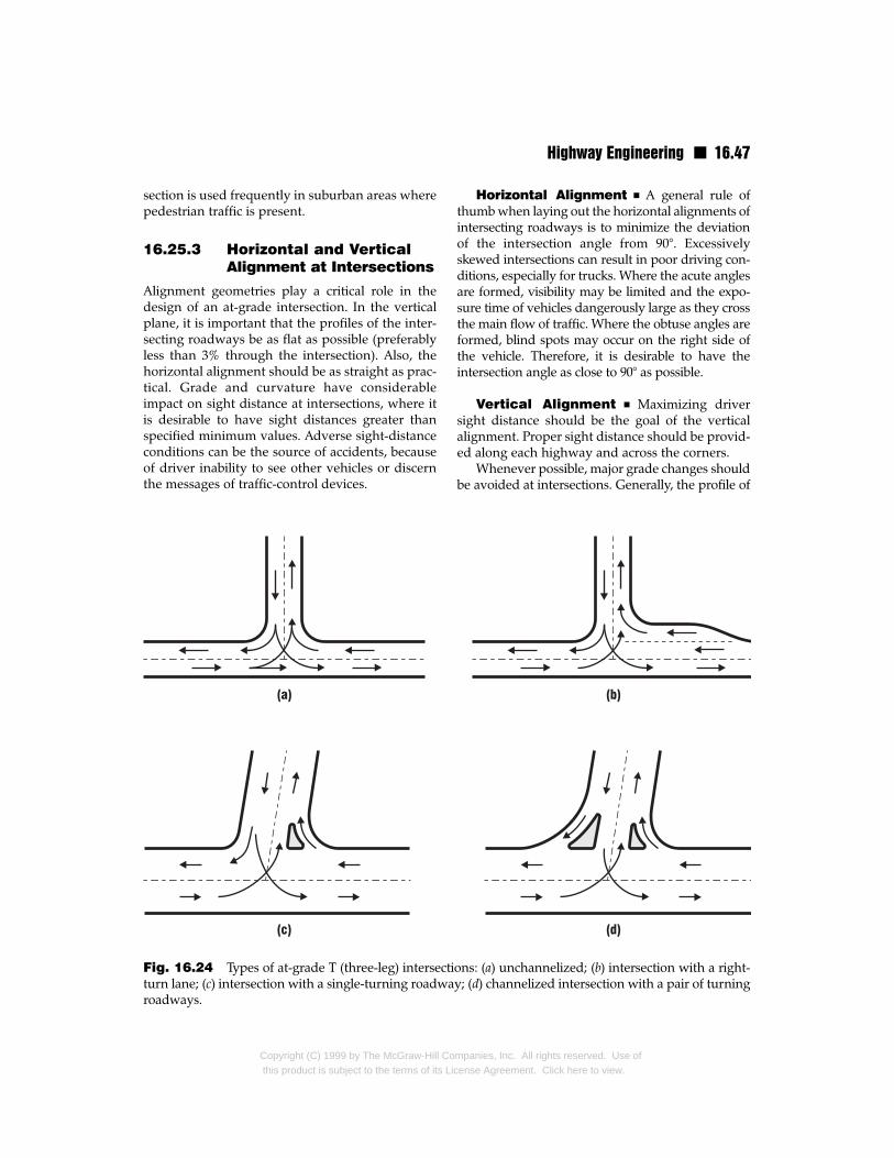
Highway Engineering n 16.47
section is used frequently in suburban areas wherepedestrian traffic is present.
16.25.3 Horizontal and VerticalAlignment at Intersections
Alignment geometries play a critical role in thedesign of an at-grade intersection. In the verticalplane, it is important that the profiles of the inter-secting roadways be as flat as possible (preferablyless than 3% through the intersection). Also, thehorizontal alignment should be as straight as prac-tical. Grade and curvature have considerableimpact on sight distance at intersections, where itis desirable to have sight distances greater thanspecified minimum values. Adverse sight-distanceconditions can be the source of accidents, becauseof driver inability to see other vehicles or discernthe messages of traffic-control devices.
Fig. 16.24 Types of at-grade T (three-leg) intersectiturn lane; (c) intersection with a single-turning roadwaroadways.
Copyright (C) 1999 by The McGraw-Hill Cothis product is subject to the terms of its Li
Horizontal Alignment n A general rule ofthumb when laying out the horizontal alignments ofintersecting roadways is to minimize the deviationof the intersection angle from 90°. Excessivelyskewed intersections can result in poor driving con-ditions, especially for trucks. Where the acute anglesare formed, visibility may be limited and the expo-sure time of vehicles dangerously large as they crossthe main flow of traffic. Where the obtuse angles areformed, blind spots may occur on the right side ofthe vehicle. Therefore, it is desirable to have theintersection angle as close to 90° as possible.
Vertical Alignment n Maximizing driversight distance should be the goal of the verticalalignment. Proper sight distance should be provid-ed along each highway and across the corners.
Whenever possible, major grade changes shouldbe avoided at intersections. Generally, the profile of
ons: (a) unchannelized; (b) intersection with a right-y; (d) channelized intersection with a pair of turning
mpanies, Inc. All rights reserved. Use ofcense Agreement. Click here to view.
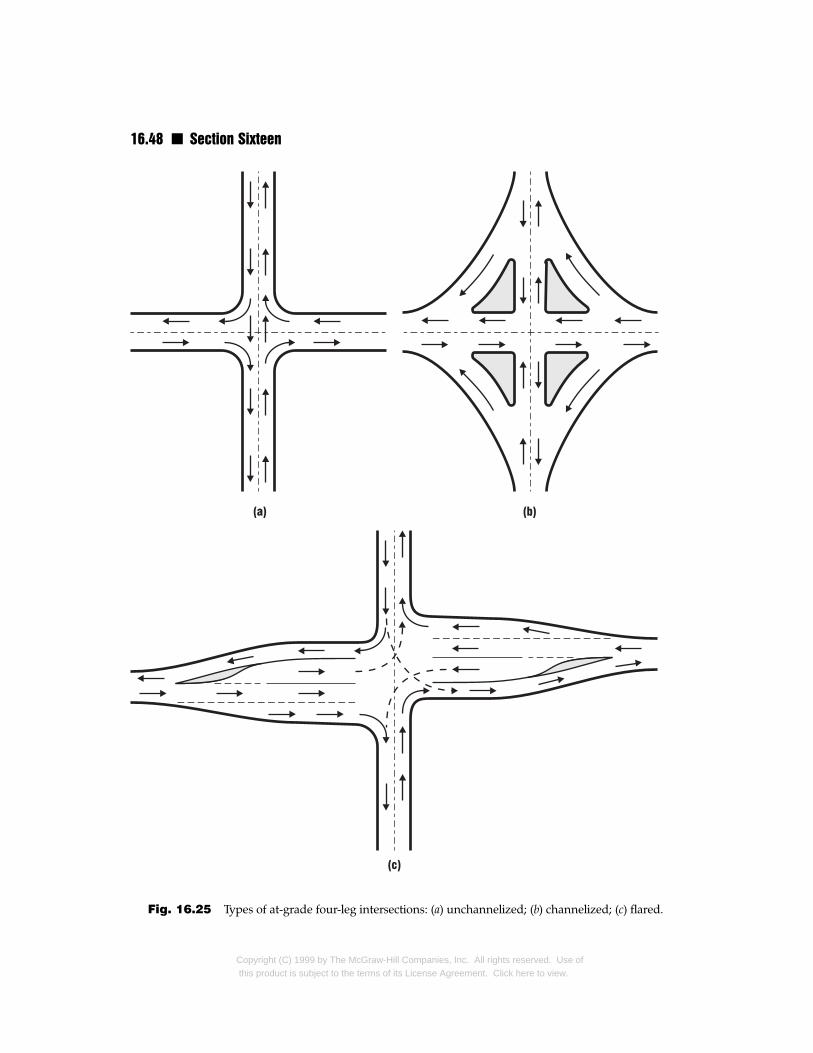
16.48 n Section Sixteen
Fig. 16.25 Types of at-grade four-leg intersections: (a) unchannelized; (b) channelized; (c) flared.
Copyright (C) 1999 by The McGraw-Hill Companies, Inc. All rights reserved. Use ofthis product is subject to the terms of its License Agreement. Click here to view.
Highway Engineering n 16.49
the major highway at an intersection should beextended through it and the profile of the minorcrossing road adjusted to match that of the majorhighway at the intersection. This may require tran-sitioning or warping the cross section of the minorroad. For low-speed, unchannelized intersectionswhere stop controls or signs are present, it may bedesirable to warp the crown of each intersectingroadway. Any alteration of the roadway cross sec-tion should be gradual and take into account theeffects on drainage.
16.25.4 Islands
An island is a defined area established betweentraffic lanes in channelized intersections to directtraffic into definite paths. It may consist of curbedmedians or areas delineated by paint. In general,islands are provided in channelized intersectionsto separate and control the angle of conflicts intraffic movement, reduce excessive pavementareas, protect pedestrians and waiting areas forturning and crossing vehicles, and provide a loca-tion for traffic-control devices.
16.26 Highway InterchangesAn interchange is a system of interconnectingroadways used in conjunction with one or moregrade separations of highways (Fig. 16.26). Itaccommodates movement of traffic between twoor more roadways at different elevations. In sodoing, it eliminates grade crossings, which may beunsafe and are inefficient in accommodating bothturning and through traffic.When highways carry-ing high volumes of traffic intersect each other, thegreatest degree of safety, efficiency, and capacity isachieved with grade separations of the highways.
There are in use numerous variations of theinterchange types shown in Fig. 16.26. They varyin size and magnitude depending on the environ-ment and scope of service for which they areintended. Design of an interchange is based ontraffic volume, topography of the site, economicconsiderations, and environmental factors.
16.26.1 Justification ofInterchanges
An interchange is not needed at every highwayintersection. The American Association of StateHighway and Transportation Officials (AASHTO)
Copyright (C) 1999 by The McGraw-Hill Cothis product is subject to the terms of its L
considers the following as warranting investigationof the advisability of selecting an interchangeinstead of an at-grade intersection: highway classi-fications, need for eliminating traffic bottlenecksand hazards, road-user benefits, and traffic volume.
Design Classification n When a highwayhas been designated to serve as a freeway (Art.16.1.1), the designer must decide whether eachintersecting highway should be terminated,rerouted, or connected to the freeway with a gradeseparation or an interchange. The goal should bemaintenance of a safe and uninterrupted flow oftraffic on the freeway. When traffic on an intersect-ing road must cross the freeway, a grade separa-tion is necessary to eliminate interference withtraffic flow on the freeway. When access from theother road to the freeway is required, an inter-change is required.
Elimination of Bottlenecks n A generaldrawback to at-grade intersections is the potential,due to high volume of traffic, for spot congestionor bottlenecks occurring at one or more of theapproaches. If an at-grade interchange cannot sat-isfy the capacity requirements of the intersectinghighways, then use of some form of interchangeshould be investigated.
Elimination of Hazards n The occurrenceof numerous accidents at an at-grade intersectionmay warrant construction of an interchange. Itsfeasibility, however, depends on the environmentin which the intersection exists. An interchangenecessitates acquisition of large amounts of right-of-way. Availability and cost of the needed land isan important consideration in deciding on aninterchange. As a result, interchanges are morelikely to be employed in rural areas than in urbanareas for elimination of hazards.
Road-User Benefits n Substitution of aninterchange for an at-grade intersection can oftenlead to direct economic benefits for users. Delaysand congestion at an at-grade intersection can becostly because of damage from accidents and theconsumption of fuel, tires, oil, and time while wait-ing for an opportunity to cross or make turns or forsignal changes. Time lost waiting at traffic signalscan be extremely severe when traffic volumes are
mpanies, Inc. All rights reserved. Use oficense Agreement. Click here to view.
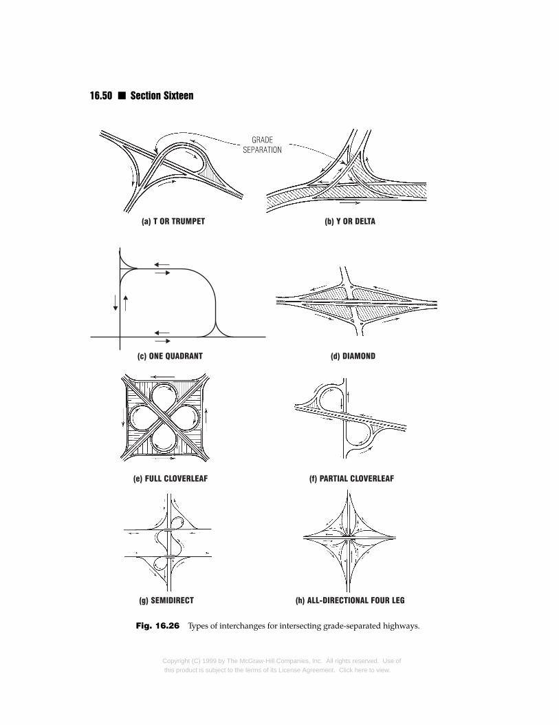
16.50 n Section Sixteen
Fig. 16.26 Types of interchanges for intersecting grade-separated highways.
Copyright (C) 1999 by The McGraw-Hill Companies, Inc. All rights reserved. Use ofthis product is subject to the terms of its License Agreement. Click here to view.
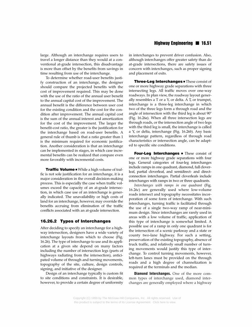
Highway Engineering n 16.51
large. Although an interchange requires users totravel a longer distance than they would at a con-ventional at-grade intersection, this disadvantageis more than offset by the benefits from savings intime resulting from use of the interchange.
To determine whether road-user benefits justi-fy construction of an interchange, the designershould compare the projected benefits with thecost of improvement required. This may be donewith the use of the ratio of the annual user benefitto the annual capital cost of the improvement. Theannual benefit is the difference between user costfor the existing condition and the cost for the con-dition after improvement. The annual capital costis the sum of the annual interest and amortizationfor the cost of the improvement. The larger thebenefit-cost ratio, the greater is the justification forthe interchange based on road-user benefits. Ageneral rule of thumb is that a ratio greater than 1is the minimum required for economic justifica-tion. Another consideration is that an interchangecan be implemented in stages, in which case incre-mental benefits can be realized that compare evenmore favorably with incremental costs.
Traffic Volume n While a high volume of traf-fic is not sole justification for an interchange, it is amajor consideration in the overall decision-makingprocess. This is especially the case when traffic vol-umes exceed the capacity of an at-grade intersec-tion, in which case use of an interchange is gener-ally indicated. The unavailability or high costs ofland for an interchange, however, may override thebenefits accruing from elimination of the trafficconflicts associated with an at-grade intersection.
16.26.2 Types of Interchanges
After deciding to specify an interchange for a high-way intersection, designers have a wide variety ofinterchange layouts from which to choose (Fig.16.26). The type of interchange to use and its appli-cation at a given site depend on many factorsincluding the number of intersection legs (parts ofhighways radiating from the intersection), antici-pated volume of through and turning movements,topography of the site, culture, design controls,signing, and initiative of the designer.
Design of an interchange typically is custom fitto site conditions and constraints. It is desirable,however, to provide a certain degree of uniformity
Copyright (C) 1999 by The McGraw-Hill Cothis product is subject to the terms of its Li
in interchanges to prevent driver confusion. Also,although interchanges offer greater safety than doat-grade intersections, there are safety issues ofconcern with interchanges, such as proper signingand placement of exits.
Three-Leg Interchanges n These consist ofone or more highway grade separations with threeintersecting legs. All traffic moves over one-wayroadways. In plan view, the roadway layout gener-ally resembles a T or a Y, or delta. A T, or trumpet,interchange is a three-leg interchange in whichtwo of the three legs form a through road and theangle of intersection with the third leg is about 90°(Fig. 16.26a). When all three intersection legs arethrough roads, or the intersection angle of two legswith the third leg is small, the interchange is calleda Y, or delta, interchange (Fig. 16.26b). Any basicinterchange pattern, regardless of through roadcharacteristics or intersection angle, can be adapt-ed to specific site conditions.
Four-Leg Interchanges n These consist ofone or more highway grade separations with fourlegs. General categories of four-leg interchangesinclude ramps in one quadrant, diamond, full clover-leaf, partial cloverleaf, and semidirect- and direct-connection interchanges. Partial cloverleafs includeinterchanges with ramps in two or three quadrants.
Interchanges with ramps in one quadrant (Fig.16.26c) are generally used where low-volumeroads intersect and topography necessitates incor-poration of some form of interchange. With suchinterchanges, turning traffic is facilitated throughthe use of a single two-way ramp of near-mini-mum design. Since interchanges are rarely used inareas with a low volume of traffic, application ofthis type of interchange is somewhat limited. Apossible use of a ramp in only one quadrant is forthe intersection of a scenic parkway and a state orcounty two-lane highway. For such a setting,preservation of the existing topography, absence oftruck traffic, and relatively small number of turn-ing movements would justify this type of inter-change. To control turning movements, however,left-turn lanes must be provided on the throughroads and a high degree of channelization isrequired at the terminals and the median.
Diamond Interchanges. One of the more com-mon types of interchange used, diamond inter-changes are generally employed where a highway
mpanies, Inc. All rights reserved. Use ofcense Agreement. Click here to view.
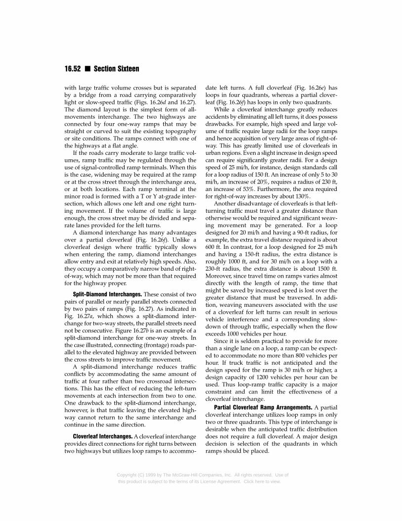
16.52 n Section Sixteen
with large traffic volume crosses but is separatedby a bridge from a road carrying comparativelylight or slow-speed traffic (Figs. 16.26d and 16.27).The diamond layout is the simplest form of all-movements interchange. The two highways areconnected by four one-way ramps that may bestraight or curved to suit the existing topographyor site conditions. The ramps connect with one ofthe highways at a flat angle.
If the roads carry moderate to large traffic vol-umes, ramp traffic may be regulated through theuse of signal-controlled ramp terminals. When thisis the case, widening may be required at the rampor at the cross street through the interchange area,or at both locations. Each ramp terminal at theminor road is formed with a T or Y at-grade inter-section, which allows one left and one right turn-ing movement. If the volume of traffic is largeenough, the cross street may be divided and sepa-rate lanes provided for the left turns.
A diamond interchange has many advantagesover a partial cloverleaf (Fig. 16.26f). Unlike acloverleaf design where traffic typically slowswhen entering the ramp, diamond interchangesallow entry and exit at relatively high speeds. Also,they occupy a comparatively narrow band of right-of-way, which may not be more than that requiredfor the highway proper.
Split-Diamond lnterchanges. These consist of twopairs of parallel or nearly parallel streets connectedby two pairs of ramps (Fig. 16.27). As indicated inFig. 16.27a, which shows a split-diamond inter-change for two-way streets, the parallel streets neednot be consecutive. Figure 16.27b is an example of asplit-diamond interchange for one-way streets. Inthe case illustrated, connecting (frontage) roads par-allel to the elevated highway are provided betweenthe cross streets to improve traffic movement.
A split-diamond interchange reduces trafficconflicts by accommodating the same amount oftraffic at four rather than two crossroad intersec-tions. This has the effect of reducing the left-turnmovements at each intersection from two to one.One drawback to the split-diamond interchange,however, is that traffic leaving the elevated high-way cannot return to the same interchange andcontinue in the same direction.
Cloverleaf Interchanges. A cloverleaf interchangeprovides direct connections for right turns betweentwo highways but utilizes loop ramps to accommo-
Copyright (C) 1999 by The McGraw-Hill Cothis product is subject to the terms of its Lic
date left turns. A full cloverleaf (Fig. 16.26e) hasloops in four quadrants, whereas a partial clover-leaf (Fig. 16.26f) has loops in only two quadrants.
While a cloverleaf interchange greatly reducesaccidents by eliminating all left turns, it does possessdrawbacks. For example, high speed and large vol-ume of traffic require large radii for the loop rampsand hence acquisition of very large areas of right-of-way. This has greatly limited use of cloverleafs inurban regions. Even a slight increase in design speedcan require significantly greater radii. For a designspeed of 25 mi/h, for instance, design standards callfor a loop radius of 150 ft. An increase of only 5 to 30mi/h, an increase of 20%, requires a radius of 230 ft,an increase of 53%. Furthermore, the area requiredfor right-of-way increases by about 130%.
Another disadvantage of cloverleafs is that left-turning traffic must travel a greater distance thanotherwise would be required and significant weav-ing movement may be generated. For a loopdesigned for 20 mi/h and having a 90-ft radius, forexample, the extra travel distance required is about600 ft. In contrast, for a loop designed for 25 mi/hand having a 150-ft radius, the extra distance isroughly 1000 ft, and for 30 mi/h on a loop with a230-ft radius, the extra distance is about 1500 ft.Moreover, since travel time on ramps varies almostdirectly with the length of ramp, the time thatmight be saved by increased speed is lost over thegreater distance that must be traversed. In addi-tion, weaving maneuvers associated with the useof a cloverleaf for left turns can result in seriousvehicle interference and a corresponding slow-down of through traffic, especially when the flowexceeds 1000 vehicles per hour.
Since it is seldom practical to provide for morethan a single lane on a loop, a ramp can be expect-ed to accommodate no more than 800 vehicles perhour. If truck traffic is not anticipated and thedesign speed for the ramp is 30 mi/h or higher, adesign capacity of 1200 vehicles per hour can beused. Thus loop-ramp traffic capacity is a majorconstraint and can limit the effectiveness of acloverleaf interchange.
Partial Cloverleaf Ramp Arrangements. A partialcloverleaf interchange utilizes loop ramps in onlytwo or three quadrants. This type of interchange isdesirable when the anticipated traffic distributiondoes not require a full cloverleaf. A major designdecision is selection of the quadrants in whichramps should be placed.
mpanies, Inc. All rights reserved. Use ofense Agreement. Click here to view.
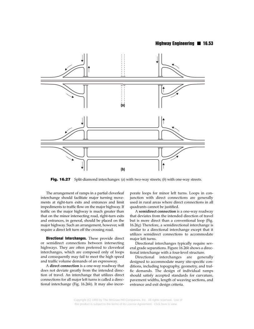
Highway Engineering n 16.53
Fig. 16.27 Split-diamond interchanges: (a) with two-way streets; (b) with one-way streets.
The arrangement of ramps in a partial cloverleafinterchange should facilitate major turning move-ments at right-turn exits and entrances and limitimpediments to traffic flow on the major highway. Iftraffic on the major highway is much greater thanthat on the minor intersecting road, right-turn exitsand entrances, in general, should be placed on themajor highway. Such an arrangement, however, willrequire a direct left turn off the crossing road.
Directional Interchanges. These provide director semidirect connections between intersectinghighways. They are often preferred to cloverleafinterchanges, which are composed only of loopsand consequently may fail to meet the high speedand traffic volume demands of an expressway.
A direct connection is a one-way roadway thatdoes not deviate greatly from the intended direc-tion of travel. An interchange that utilizes directconnections for all major left turns is called a direc-tional interchange (Fig. 16.26h). It may also incor-
Copyright (C) 1999 by The McGraw-Hill Cothis product is subject to the terms of its Li
porate loops for minor left turns. Loops in con-junction with direct connections are generallyused in rural areas where direct connections in allquadrants cannot be justified.
A semidirect connection is a one-way roadwaythat deviates from the intended direction of travelbut is more direct than a conventional loop (Fig.16.26g) Therefore, a semidirectional interchange issimilar to a directional interchange except that itutilizes semidirect connections to accommodatemajor left turns.
Directional interchanges typically require sev-eral grade separations. Figure 16.26h shows a direc-tional interchange with a four-level structure.
Directional interchanges are generallydesigned to accommodate many site-specific con-ditions, including topography, geometry, and traf-fic demands. The design of individual rampsshould satisfy accepted standards for curvature,pavement widths, length of weaving sections, andentrance and exit design criteria.
mpanies, Inc. All rights reserved. Use ofcense Agreement. Click here to view.
16.54 n Section Sixteen
16.26.3 Selection of Interchanges
The type of interchange to select is one that bestmeets the needs of the site and provides opera-tional efficiency and safety, and adequate capacityfor anticipated traffic volumes and turning pat-terns. It is advisable to choose the type of inter-change before final route selection. This permits adetermination that the interchange type selectedcan be adequately developed.
Interchanges generally fall into two basic cate-gories: system interchanges and service inter-changes. The former includes interchanges thatconnect one freeway to another. In contrast, ser-vice interchanges connect a freeway to a road witha lower-grade classification. In a rural environ-ment, service demand is a principal issue.
When the intersecting roadways are freeways,all-directional interchanges may be advantageousto facilitate high turning volumes. When only someturning volumes are high, a combination of direc-tional, semidirectional, and loop ramps may proveadvantageous. Where directional or semidirection-al interchanges are used in conjunction with loops,however, weaving sections should be avoided.
A cloverleaf interchange is the minimum typeto use at the intersection of two highways both ofwhich have partial or full control of access. Clover-leafs are also advantageous for intersections whereleft turns at grade are prohibited. A diamond inter-section is appropriate where a major highwayintersects a minor road. A partial cloverleaf may beadvisable where traffic volumes or site conditionsdo not warrant or allow employment of a fullcloverleaf interchange.
Interchanges for highways in urban areasshould be selected on a systemwide rather thanindividual basis. Since interchanges are usuallyclosely spaced in urban environments, an inter-change may influence selection and design of pre-ceding and subsequent interchanges. For example,additional lanes may be required to accommodatecapacity, weaving, and lane-balance requirements.
A general rule of thumb is that a minimuminterchange spacing of 1 mi should be used inurban areas, but a closer spacing may be used ifgrade-separated ramps are provided or collector-distributor roads are added. A minimum spacingof 2 mi should be used in rural regions.
Copyright (C) 1999 by The McGraw-Hill Cothis product is subject to the terms of its Li
16.26.4 Ramps in Interchanges
A ramp is a roadway that connects two or morelegs of an interchange and is used for turning traf-fic (Fig. 16.28). The main elements of a ramp are aconnecting roadway and a terminal at each end.The profile of the connecting roadway typically issloped and the horizontal alignment is curved. Ingeneral, design criteria for horizontal and verticalalignments of ramps are less restrictive than thoseof the intersecting highways, but sometimes thedesign criteria are the same.
In design of a ramp, the designer has to balanceseveral factors. For example, consider topographyand costs of right-of-way, which influence selec-tion and design of the ramp. To conserve land, itmay be necessary to locate the ramp so close to thehighway that a retaining wall must be constructed.The cost of the wall then has to be balanced againstthe cost of acquiring additional right-of-way toeliminate need for the wall.
The type of ramp to use depends on the type ofinterchange. A trumpet interchange, for example,utilizes one loop, one semidirectional ramp, andtwo right directional or diagonal ramps (Figs.16.26a and 16.28). Usually, a ramp is a one-wayroadway. Some ramps, such as a diagonal ramp,are one-way but allow both left and right turns ata terminal on a minor intersecting road.
Ramp Design Speeds n The design speedfor a ramp generally should be about the same asthat for the intersecting highway with the lowertraffic volume. Although lower ramp speeds maybe necessary, the design ramp speed used shouldnot be less than the values presented in Table 16.9.The table lists, as a guide, ramp design speeds to beused with various highway design speeds.
When a ramp connects a high-speed highwaywith a minor road or a city street, provision shouldbe made for a considerable reduction in speed fortraffic leaving the high-speed highway. An initialspeed reduction can be accomplished through useof a deceleration lane on the main highway. Toallow for continuing deceleration on the ramp, theradii of the curves on the ramp should be reducedin stages. At the ramp terminal at the minor road,it may be necessary to provide some form of signalor signing to stop or slow vehicles.
mpanies, Inc. All rights reserved. Use ofcense Agreement. Click here to view.
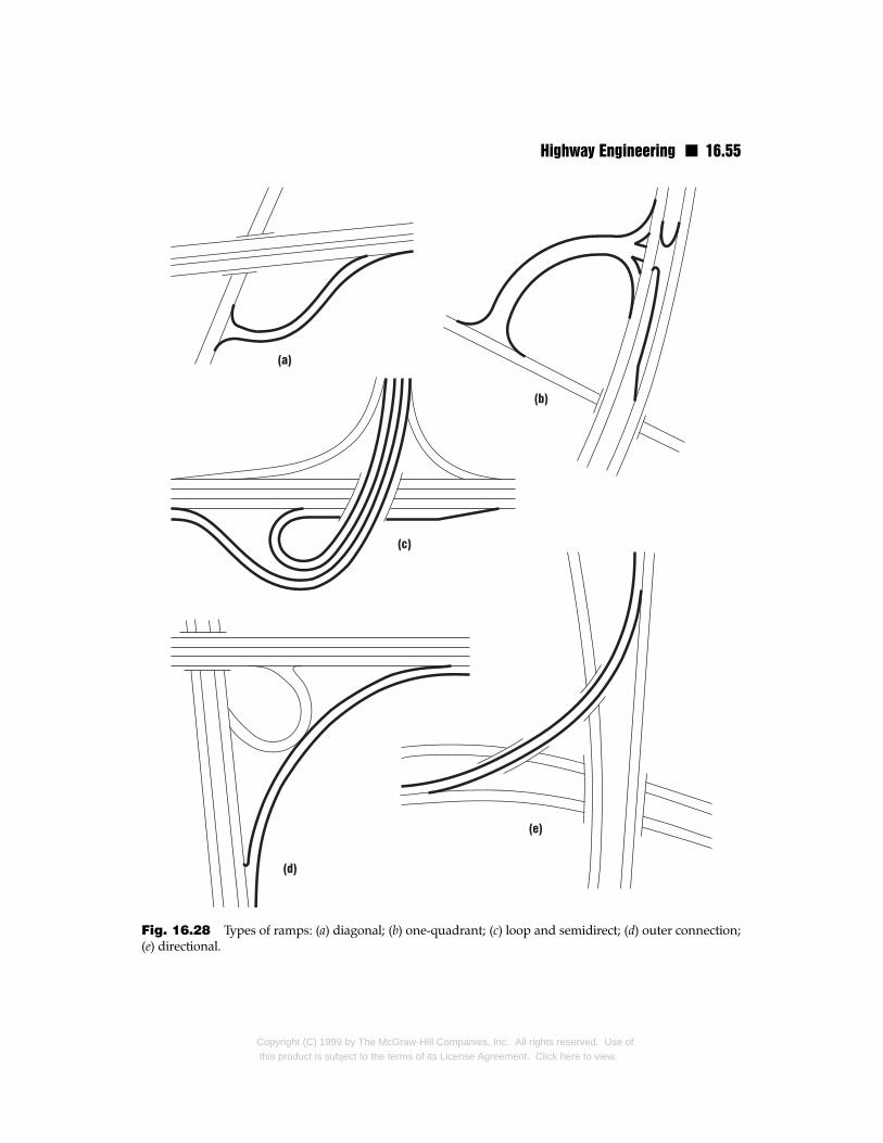
Highway Engineering n 16.55
Fig. 16.28 Types of ramps: (a) diagonal; (b) one-quadrant; (c) loop and semidirect; (d) outer connection;(e) directional.
Copyright (C) 1999 by The McGraw-Hill Companies, Inc. All rights reserved. Use ofthis product is subject to the terms of its License Agreement. Click here to view.
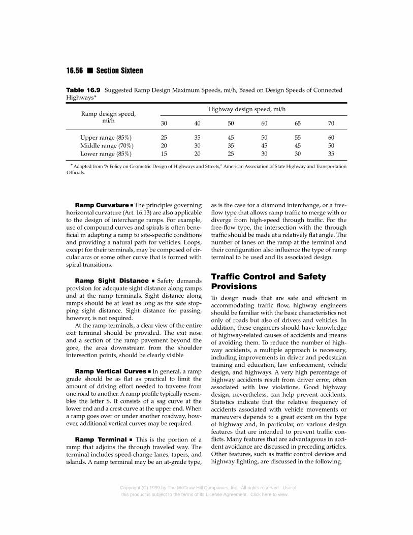
16.56 n Section Sixteen
Highway design speed, mi/h
30 40 50 60 65 70
Upper range (85%) 25 35 45 50 55 60Middle range (70%) 20 30 35 45 45 50Lower range (85%) 15 20 25 30 30 35
*Adapted from “A Policy on Geometric Design of Highways and Streets,” American Association of State Highway and TransportationOfficials.
Table 16.9 Suggested Ramp Design Maximum Speeds, mi/h, Based on Design Speeds of ConnectedHighways*
Ramp design speed,mi/h
Ramp Curvature n The principles governinghorizontal curvature (Art. 16.13) are also applicableto the design of interchange ramps. For example,use of compound curves and spirals is often bene-ficial in adapting a ramp to site-specific conditionsand providing a natural path for vehicles. Loops,except for their terminals, may be composed of cir-cular arcs or some other curve that is formed withspiral transitions.
Ramp Sight Distance n Safety demandsprovision for adequate sight distance along rampsand at the ramp terminals. Sight distance alongramps should be at least as long as the safe stop-ping sight distance. Sight distance for passing,however, is not required.
At the ramp terminals, a clear view of the entireexit terminal should be provided. The exit noseand a section of the ramp pavement beyond thegore, the area downstream from the shoulderintersection points, should be clearly visible
Ramp Vertical Curves n In general, a rampgrade should be as flat as practical to limit theamount of driving effort needed to traverse fromone road to another. A ramp profile typically resem-bles the letter S. It consists of a sag curve at thelower end and a crest curve at the upper end. Whena ramp goes over or under another roadway, how-ever, additional vertical curves may be required.
Ramp Terminal n This is the portion of aramp that adjoins the through traveled way. Theterminal includes speed-change lanes, tapers, andislands. A ramp terminal may be an at-grade type,
Copyright (C) 1999 by The McGraw-Hill Cothis product is subject to the terms of its Lic
as is the case for a diamond interchange, or a free-flow type that allows ramp traffic to merge with ordiverge from high-speed through traffic. For thefree-flow type, the intersection with the throughtraffic should be made at a relatively flat angle. Thenumber of lanes on the ramp at the terminal andtheir configuration also influence the type of rampterminal to be used and its associated design.
Traffic Control and SafetyProvisionsTo design roads that are safe and efficient inaccommodating traffic flow, highway engineersshould be familiar with the basic characteristics notonly of roads but also of drivers and vehicles. Inaddition, these engineers should have knowledgeof highway-related causes of accidents and meansof avoiding them. To reduce the number of high-way accidents, a multiple approach is necessary,including improvements in driver and pedestriantraining and education, law enforcement, vehicledesign, and highways. A very high percentage ofhighway accidents result from driver error, oftenassociated with law violations. Good highwaydesign, nevertheless, can help prevent accidents.Statistics indicate that the relative frequency ofaccidents associated with vehicle movements ormaneuvers depends to a great extent on the typeof highway and, in particular, on various designfeatures that are intended to prevent traffic con-flicts. Many features that are advantageous in acci-dent avoidance are discussed in preceding articles.Other features, such as traffic control devices andhighway lighting, are discussed in the following.
mpanies, Inc. All rights reserved. Use ofense Agreement. Click here to view.
Highway Engineering n 16.57
16.27 Traffic Control DevicesThese provide for the safe and orderly movementof traffic on a highway by offering guidance andnavigation information to drivers. Commonlyused traffic control devices include traffic signalsand signs that display regulatory warnings androute information. Other forms include pavementmarkings and delineators.
An effective traffic control device should com-mand attention, convey a clear and simple mean-ing, acquire the respect of drivers, and allow ade-quate time for drivers to respond. Traffic controldevices should be uniform, treating similar situa-tions in the same fashion. Consistent use of sym-bols and location of signs and other traffic controldevices helps to give drivers sufficient responsetime for reacting to traffic messages.
16.27.1 Traffic Signs
In general, traffic signs may be classified as regula-tory, warning, or guide. Regulatory signs are usedto indicate the required method of traffic move-ment. Examples of regulatory signs include STOPand YIELD signs used on intersecting roadways toestablish the right of through movement. Warningsigns, such as a FALLEN ROCK ZONE sign, areused to indicate potentially hazardous conditions.Variable message signs are used under remote con-trol or automatic sensors, among other purposes,to convey emergency warnings. Guide signs, suchas exit signs on a freeway, are used to direct trafficalong a route toward a destination.
Placement and design of signs should be anintegral part of highway design, especially inpreparation of highway geometry. Such anapproach will help ensure that future adverse oper-ational conditions will be minimized or eliminated.
Signs are typically manufactured from light-reflective materials. In areas of high traffic and inconstruction zones, illuminated signs are often used.
16.27.2 Delineators
These are reflectors that are used to guide traffic,especially at night. They may be mounted above-ground or fixed to the pavement. In the latter case,delineators may act as a compliment to or replace-ment of conventional pavement markings (Art.16.27.3) and are known as raised pavement delin-eators. Because they are subject to uprooting by
Copyright (C) 1999 by The McGraw-Hill Cothis product is subject to the terms of its Li
snowplow blades, use of this type of delineator asa permanent marker is more predominant in warmclimates than in cold ones. Raised pavement delin-eators, however, are commonly used in any envi-ronment as construction zone markers to delineatetemporary travel lanes.
When mounted on a post, delineators arereflectors typically made of faceted plastic or glass.These units are installed at specific heights andspacings to delineate the horizontal alignment,typically in regions where alignment changes maybe confusing or ill-defined. Delineators at inter-changes are usually different in color and multiple-mounted to differentiate the interchange area fromthe roadway proper.
16.27.3 Pavement Markings
Pavement markings are markers that are on theroadway surface and that are used to regulate andguide movement of traffic in a safe, orderly, andefficient manner. The forms of pavement markingsinclude centerline stripes, lane lines, no-passingbarriers, and edge striping. Painting is the mostcommon method of applying pavement markings.An alternative is plastic striping fixed to pavementwith an adhesive. This method is often used formarking temporary lanes. For the pavement mark-ings to fulfill their intended functions, they must bevisible, and for this, they must be properly main-tained by cleaning and renewal when required.
16.27.4 Traffic SignalsTraffic signals are used to assign the right-of-way atintersections and thereby control the flow of vehic-ular and pedestrian traffic. Signals can also be usedto emphasize a hazardous location, supplementconventional signs, and provide control at rail-road-highway grade crossings.
Red, yellow (amber), and green signal lights arewidely used. Depending on the type of intersection,the displays may have a circular or arrow configu-ration. Care should be taken in placement of trafficsignals to ensure visibility, meet pedestrian require-ments, and effect integration of the signals with thehighway geometry. The design of a traffic signalsystem should also allow for future expansion.
Traffic signals may be pretimed, traffic-actuat-ed, or pedestrian-activated. Pretimed signals oper-ate on a predetermined, consistent, and regularlyrepeated sequence of intervals. Traffic-actuated
mpanies, Inc. All rights reserved. Use ofcense Agreement. Click here to view.
16.58 n Section Sixteen
controls utilize some form of vehicle and pedestri-an detector that trips the signal to allow assignedmovements. Typical uses of traffic-actuated signalsare to control left turns and traffic flow from sideroads, movements that are not permitted until avehicle trips, or actuates, a time-delay detector.Pedestrian-actuated signals allow normal vehicularmovement until a pedestrian presses a button thatchanges the signal light, halting traffic and allow-ing the pedestrian to cross safely.
Signal Systems n These are used to coordi-nate the movement of traffic through intersectionson major highways located in and on approachesto cities and large villages. In signal systems, a mas-ter controller resynchronizes various intersectionalsignal controllers to reduce the inconvenience anddelays resulting from independent control of traf-fic signals in cities and large villages.
16.27.5 Colored Pavement
Another method of delineating pavement sectionsto guide and regulate traffic is to color sections ofthe pavement, such as shoulders (Art. 16.5). Inorder for colored pavement to serve successfully asa traffic control device, it should provide signifi-cant contrast with adjoining paved areas.
16.27.6 Ramp control
It is sometimes necessary to control entry of vehiclesto limited-access highways from ramps. This pur-pose may be achieved in several ways. One way isto close the ramps. This involves complete diversionof ramp traffic. Another way is to apply rampmetering. This requires drivers to stop and waitbefore entering the highway when ramp traffic flowmust be restricted. An alternative is merge control,which employs a ramp-metering system that stopsvehicles at the ramp terminal when there is steadytraffic on the highway and releases them when thesystem detects a gap in the highway traffic.
16.27.7 Traffic Surveillance andControl Systems
These utilize video and related equipment to mon-itor traffic manually. The objective is to keep trafficflowing as orderly and efficiently as possible. Traf-fic surveillance and control systems can range
Copyright (C) 1999 by The McGraw-Hill Cothis product is subject to the terms of its Lic
from limited types that use conventional detectorsto elaborate systems that employ vehicle detectionloops, helicopters, and video equipment.
The goal of traffic surveillance and control sys-tems is to provide from remote locations observa-tion of traffic movements and permit immediateidentification of demands for service. These sys-tems can also play an invaluable role in promotinghighway safety by facilitating immediate recogni-tion of emergencies. In such situations, the con-trollers can promptly notify the proper authoritieswho can take appropriate actions to dispatch aid tothe scene. The controllers also can initiate manage-ment of traffic flow through the use of variablemessage signs (Art. 16.27.1).
16.28 Intelligent VehicleHighway Systems
A major intent of the Intermodal Surface Trans-portation Efficiency Act (ISTEA) of 1991 is to pro-mote research and development in interfacing ofhighways with other forms of transportation,including railroads, aviation, shipping, and masstransit. A key component of ISTEA is its emphasison innovation and new technologies, such as intel-ligent vehicle highway systems (IVHS) and mag-netic levitation systems (MAGLEV) for railways.
An IVHS is a collection of systems that address avariety of different objectives. Some elements of anIVHS, like variable message signs, are commonplace.Still others, such as in-vehicle displays and travelerinformation screens, are gradually being adopted.
16.18.1 Advanced TrafficManagement Systems(ATMS)
This is a component of an IVHS that has the abili-ty to detect accidents, construction work, andother causes of traffic backup and congestion. TheATMS also may offer alternate paths for vehicles inan effort to dispel congestion and provide optimaluse of the open highway system.
An ATMS is essentially a form of traffic surveil-lance and control system (Art. 16.27.7). Two impor-tant aspects of an ATMS are the type and locationof detection equipment used to identify points ofincident. An ATMS requires robust detectors inorder to provide necessary information. Loop
mpanies, Inc. All rights reserved. Use ofense Agreement. Click here to view.
Highway Engineering n 16.59
detectors are often used in IVHS, since they gener-ally are less expensive and more reliable than cur-rently available video-image processing. Loopdetectors alone, however, do not provide all theinformation needed for proper management oftraffic congestion. They require supplementing byother technologies, such as closed-circuit television(CCTV), which can provide personnel located in acontrol center with more specific information con-cerning incidents. Typically, implementation ofCCTV is confined to major highways and bottle-neck points on minor roads.
16.28.2 Advanced TravelerInformation Systems (ATIS)
These are components of an IVHS that providedrivers with in-vehicle navigational informationand real-time data concerning the location ofexisting or potential traffic conflicts. An ATIS mayalso suggest alternative travel routes.
16.28.3 Advanced Vehicle ControlSystems (AVCS)
These are components of an IVHS that are designedto give advance warning to drivers of potential colli-sion with other vehicles. An AVCS may be able auto-matically to brake vehicles if a collision is imminentor direct vehicles away from a potential collision.
16.28.4 Commercial VehicleOperation (CVO)
These are components of an IVHS that monitormovements of trucks, buses, vans, taxis, and emer-gency vehicles. Tracking of commercial vehicleshas many benefits. One benefit is that CVO facili-tates automation of toll collection, which greatlyhelps in reducing congestion at toll collection facil-ities. Another benefit is the ability to track move-ments of hazardous material and of large vehiclesthat exceed legal truck-load limitations.
16.28.5 Advanced PublicTransportation Systems(APTS)
In addition to benefiting users of highway, an IVHSis also designed to benefit the users of mass transit orhigh-occupancy vehicles (HOV) through incorpora-
Copyright (C) 1999 by The McGraw-Hill Cothis product is subject to the terms of its Li
tion of an advanced public transportation system.An HOV may be a bus, van with more than one pas-senger, or car pool. The goals of an APTS are toreduce operating costs for transit systems and pro-mote use of transit systems through increased effi-ciency. An APTS allows transit riders to prepay faresand receive in evidence of the payment a smart cardthat can be used to gain access to transit vehicles.
16.29 Highway LightingNighttime illumination of a roadway is veryimportant in promoting safety and operationalefficiency. As with any highway appurtenance,however, there is an associated cost that should bebalanced against the enhancement offered.
In general, lighting is used more extensively forurban rather than rural roadways. In addition tofurthering highway safety, lighting in urban envi-ronments promotes safety to pedestrians. In ruralareas, lighting is generally applied in critical areas,such as interchanges, intersections, railroad cross-ings at grade, narrow or long bridges, tunnels,sharp curves, and areas where roadside interfer-ence is a concern.
A typical highway lighting installation consists ofan aluminum or steel standard (pole) on top ofwhich is mounted a luminaire (Fig. 16.29). This light-ing fixture comprises a lamp, its housing, and a lens.
Like other roadside elements, lighting standardsare susceptible to vehicle impact and thereforeshould be placed outside the roadway clear zone. Ifit is not possible or practical to locate the standardsin a safe area, the standards should be equippedwith some form of impact-attenuation feature. Forthis purpose, breakaway poles may be used. Theyshould be installed along stretches of roadwaywhere vehicles should be traveling at relatively lowspeeds at which damage to a vehicle striking a stan-dard will not be severe. Breakaway poles should notbe used, however, in heavily developed regions,where there is the possibility of an impacted poledamaging adjacent buildings or pedestrians.
Installation of poles on the outside of curves on aramp should also be avoided because in such loca-tions they are likely to be struck by a vehicle. If light-ing standards are placed behind a longitudinal trafficbarrier, they should be offset to allow for deflection ofthe longitudinal barrier when it is impacted.
When installed for a divided highway, lightingstandards may be placed either in the median (Fig.
mpanies, Inc. All rights reserved. Use ofcense Agreement. Click here to view.
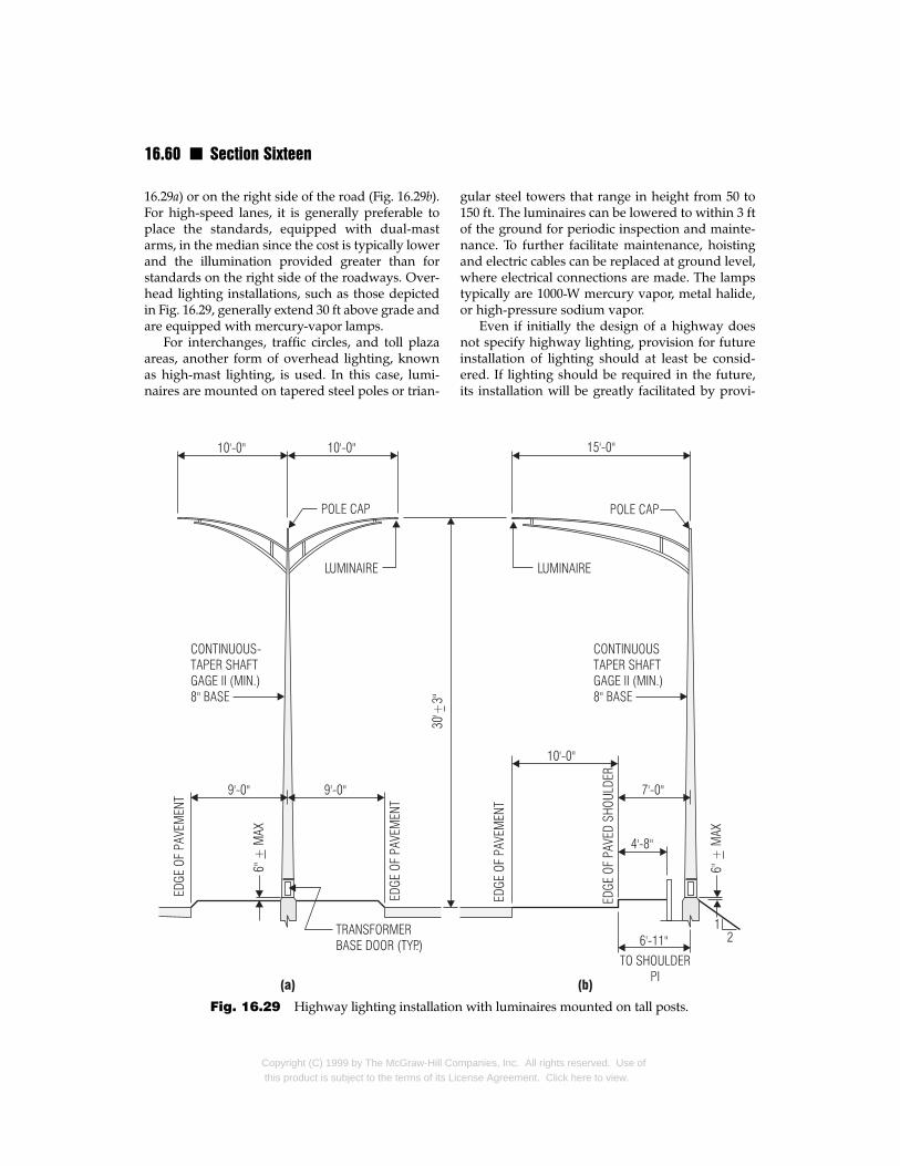
16.60 n Section Sixteen
16.29a) or on the right side of the road (Fig. 16.29b).For high-speed lanes, it is generally preferable toplace the standards, equipped with dual-mastarms, in the median since the cost is typically lowerand the illumination provided greater than forstandards on the right side of the roadways. Over-head lighting installations, such as those depictedin Fig. 16.29, generally extend 30 ft above grade andare equipped with mercury-vapor lamps.
For interchanges, traffic circles, and toll plazaareas, another form of overhead lighting, knownas high-mast lighting, is used. In this case, lumi-naires are mounted on tapered steel poles or trian-
Fig. 16.29 Highway lighting installatio
Copyright (C) 1999 by The McGraw-Hill Cothis product is subject to the terms of its L
gular steel towers that range in height from 50 to150 ft. The luminaires can be lowered to within 3 ftof the ground for periodic inspection and mainte-nance. To further facilitate maintenance, hoistingand electric cables can be replaced at ground level,where electrical connections are made. The lampstypically are 1000-W mercury vapor, metal halide,or high-pressure sodium vapor.
Even if initially the design of a highway doesnot specify highway lighting, provision for futureinstallation of lighting should at least be consid-ered. If lighting should be required in the future,its installation will be greatly facilitated by provi-
n with luminaires mounted on tall posts.
mpanies, Inc. All rights reserved. Use oficense Agreement. Click here to view.
Highway Engineering n 16.61
sion of the necessary conduits under pavementsand curbs during construction of the highway.
(“An Informational Guide for Roadway Light-ing,’’ American Association of State Highway andTransportation Officials, Washington, D.C.)
Highway Maintenance andRehabilitationMaintenance and rehabilitation of highway pave-ments are ongoing activities, critical for prolongingthe life of highways. Methods for performing thesetasks vary from region to region and depend onthe type of pavement.
16.30 Maintenance of AsphaltPavements
Deterioration of an asphalt pavement is evidencedby distortion and various forms of cracking.
16.30.1 Distortions of AsphaltPavements
A distortion is a change of a pavement from itsoriginal shape. Asphalt pavements can suffer froma variety of distortions that can cause cracking andother adverse conditions. The principal forms ofpavement distortions are channeling (rutting), cor-rugations, shoving, depressions, and upheaval.
Channeling is a lengthy depression formed inwheel tracks. Corrugation (washboarding) is theplastic movement of an asphalt surface that causesformation of ripples across the pavement. Shoving
is plastic movement that results in a localizedbulge in the pavement. Upheaval is the localizedupward displacement of a pavement brought onby swelling of the subgrade or other portion of thepavement structure.
16.30.2 Cracking of AsphaltPavements
This has many causes and takes a variety of forms,such as alligator, edge, joint, reflection, slippage,transverse, longitudinal, and diagonal cracking.
Alligator Cracking n Cracks that form smallinterlocking rectangular shapes having theappearance of alligator skin are known as alligator
Copyright (C) 1999 by The McGraw-Hill Cothis product is subject to the terms of its Li
cracks. These usually are initiated by failure of anuntreated granular base or by a soft subgrade layer.Such conditions often arise from excessive satura-tion of pavement base or subgrade.
Maintenance generally involves removal of allwet material and patching with a full-depth hot-mix asphalt. To prevent future occurrence of alliga-tor cracking, new drainage facilities should beinstalled or existing drainage facilities should beimproved (Arts. 16.16 and 16.17).
Edge Cracking n Located at or near theedges of pavements, edge cracking extends longi-tudinally, nearly parallel to the centerline of theroadway. This type of cracking may be accompa-nied by transverse cracks, nearly perpendicular tothe roadway centerline. Causes of edge crackinginclude settlement of the pavement, inadequatesupport for the pavement, inadequate drainage,and frost heave.
Repair of edge cracks requires filling the crackswith asphalt-emulsion slurry or cutback asphaltmixed with sand. If settlement has occurred, it maybe necessary to bring the roadway surface to gradethrough use of hot-mix asphalt patching.
Joint Cracking n This occurs at the interfacebetween a pavement and adjacent shoulder. Jointcracking can be initiated by deformational loads dueto thermal expansion and contraction or alternatewetting and drying. It also can be caused by intru-sion of water as a result of inadequate drainage.
A crack between two adjacent paving lanes isknown as a lane-joint crack. It typically is causedby inadequate bond or a poor seam betweenadjoining sections of pavement.
Repair of joint cracks requires filling of thecracks with an asphalt-emulsion slurry. In addition,poor drainage conditions should be corrected.
Reflection Cracking n This is a crack thatforms in an asphalt overlay and reflects the pat-tern of the underlying pavement surface. Reflec-tion cracking can be induced by horizontal or ver-tical movements in the pavements beneath theoverlay. These movements are generally causedby traffic loads, earth movement, or temperature.Reflection cracks typically occur in asphalt over-lays placed on top of a portland cement concreteor cement-treated base.
mpanies, Inc. All rights reserved. Use ofcense Agreement. Click here to view.
16.62 n Section Sixteen
Cracks less than 1/8 in wide may either beignored or, if intrusion of water is a concern, filled,with the use of a squeegee, with emulsified or cut-back asphalt covered with sand. Cracks more than¼ in wide should be filled with an asphalt-emul-sion slurry or a light grade of cutback asphalt andfine sand.
Shrinkage Cracking n This is evidenced byinterconnected cracks that create a series of largeblocks with sharp corners or angles. Shrinkagecracks are usually associated with a volume changein the pavement asphalt mix, base, or subgrade.They also may result from aging of the pavement.The constant exposure of the pavement materialsto thermal expansion and contraction, may causethem to lose some of their elasticity or resiliencyand bring about shrinkage cracking.
Slippage Cracking n These are crescent-shaped cracks generated by traffic-induced hori-zontal forces. Slippage cracks are caused by insuf-ficient bond between the surface layer and theunderlying course. Dust, dirt, and oil atop theunderlying course during placement of the surfacecourse can contribute to this lack of bond. Also,omission of a tack coat during construction canlead to formation of slippage cracks.
This type of cracking is repaired by removingthe surface layer around the crack to locationswhere an adequate bond is present. The area fromwhich the surface course was removed is thenpatched with a hot-mix asphalt.
(“The Asphalt Handbook,” The Asphalt Insti-tute, College Park, Md. See also Art. 16.32.)
16.31 Maintenance of PortlandCement–ConcretePavements
Deterioration of a portland cement–concrete pave-ment (PCC) is evidenced by distortion and variousforms of cracking. Consequently, much mainte-nance work is concerned with filling of cracks andexpansion joints. For this purpose, asphalt is oftenused. It is suitable for sealing joints and cracks, fill-ing small cavities, and raising sunken slabs. A moreextreme alternative in maintaining PCC pave-ments is to cover deteriorated pavement with athin asphalt course (overlay).
Copyright (C) 1999 by The McGraw-Hill Cothis product is subject to the terms of its Lic
16.31.1 Distortions of PCCPavements
Major forms of distortion in PCC pavements arefaults and pumping. A fault is a physical differ-ence in elevation between two slabs located at ajoint or a crack. Pumping is the upward anddownward movement of a slab under traffic loads.This may occur when pavements overlay very wetsand, clay, or silt. Pumping typically takes place attransverse and longitudinal joints and edgecracks. It may be corrected by inserting asphalt orportland cement grout under the slab and improv-ing the drainage.
16.31.2 Cracking of PCCPavements
This has many causes and takes a variety of form,such as transverse, longitudinal, and diagonalcracking.
Transverse Cracking n Extending roughlyperpendicular to the pavement centerline, trans-verse cracking may be caused by overloading ofthe pavement, pumping of slabs, failure of a softfoundation, frozen joints, lack of joints, excessivelyshallow joints, or concrete shrinkage. Repair usual-ly requires that the cracks be cleaned of all loosematerial by routing, compressed air, or sandblast-ing and then filled with a rubber-asphalt sealer.Cracks generated by pumping should be providedwith an asphalt underseal.
Longitudinal Cracking n This extendsroughly parallel to the pavement centerline. Lon-gitudinal cracking can be caused by shrinkage ofthe concrete, especially in wide pavements with-out a longitudinal joint. Other conditions that cancreate longitudinal cracking are pumping or anexpansive subbase or subgrade.
Repair of longitudinal cracks in PCC pave-ments is the same as that for transverse cracking.For pumping-induced cracks, a high-softening-point asphalt may be used to fill the voids underthe pavement slab.
Diagonal Cracking n These run diagonallyto the pavement centerline. They are induced bytraffic loads on an unsupported end of the pave-ment slab.
mpanies, Inc. All rights reserved. Use ofense Agreement. Click here to view.
Highway Engineering n 16.63
Repair of the cracks is like that described fortransverse and longitudinal cracking. As may bedone for pumping-type cracks, an asphalt undersealmay be applied to the slab and followed by filling ofthe crack with a rubber-asphalt sealing compound.
See also Art. 16.32.
16.32 Pavement ManagementSystems (PMS)
Constant exposure to the elements, combined withwear and tear from traffic, make highways extreme-ly prone to deterioration. As a result, they must berepaired or replaced if they are to serve as intended.Highway maintenance and rehabilitation, however,is not limited just to application of the remedialmeasures described in Arts. 16.30 and 16.31.
Responsible for maintenance of immenselengths of roadway and associated appurtenancefacilities, transportation agencies frequently haveto decide which sections of highway need immedi-ate attention and which can be deferred. A varietyof factors influence this decision, and highwaydesign is only one of these factors, albeit an impor-tant one. Economic, political, and a host of otherfactors must be evaluated before project selectionmay be made. The main objective of a pavementmanagement system (PMS) is to assist in makingthis decision. The human component of a PMS isessential in the decision-making process, but prop-er use of computer software can play an importantrole in the decision-making process.
The basic components and associated productsof a PMS are as follows: inventory database, main-tenance database, budgetary information, projectselection methods, and costing models.
The inventory database of a PMS details pave-ment conditions throughout the entire highwaynetwork. There are many ways to define the stateof a section of pavement. One method is to rate thepavement in terms of various forms of pavementdistress, such as edge cracking and rutting, asdescribed in Arts. 16.30 and 16.31. The length of thepavement section to be rated depends on the detaildesired. Use of small lengths, however, does notnecessarily translate into a more accurate pictureof pavement condition.
Typically, information on pavement condition isstored in a computerized database managementsystem (DBMS) for both querying and modeling.
Copyright (C) 1999 by The McGraw-Hill Cothis product is subject to the terms of its Li
The data may also be tied into a geographic infor-mation system (GIS), which allows excellent visual-ization of data. Historical data contained within themaintenance database describe what work has beenperformed on the pavement sections. The data arehelpful in determining both the results of individualremedial methods and associated costs. Budgetaryinformation may be derived from the inventory andmaintenance databases. Based on the data thusmade conveniently available, project selection andcost analysis methods can be applied to assist inselection of the sequence in which projects are to beimplemented and formulation of highway mainte-nance and rehabilitation budgets.
16.32.1 Project and NetworkLevel Analyses
A PMS can function using a project or network levelanalysis approach, or both. Project level analysisdeals with individual sections of pavement and theremedial measures to be taken to correct deficien-cies. Associated cost estimating can be performedand ramifications of various remedial measures canbe predicted with the objective of determiningwhich method and level of repair will yield the bestresults in terms of both economy and safety.
Network level analysis is applicable to a groupof projects comprising various sections of noncon-tiguous highway. This analysis permits formula-tion of alternatives based on the maintenance andrehabilitation needs not only of specific highwaysections but also of the highway network as awhole. For example, one section of the networkmay require patching of alligator cracking andanother may show evidence of subsurfacedrainage inadequacies. If funds are insufficient forcorrecting both conditions, the PMS could assist inthe decision whether to correct the drainage con-dition, which if ignored could lead to failure of thepavement, or to patch the cracking, which shouldnot be ignored but may be deferred for a short timewithout serious consequences. While this is a rela-tively simple example, it serves to illustrate thebasic concepts behind network level analysis.
In addition to providing analysis, the PMSoffers valuable support information in the form ofcost and record data and ancillary backup infor-mation that can be used not only for formulatingbut also for justifying maintenance plans. Devel-opment of a PMS builds upon methods and infor-
mpanies, Inc. All rights reserved. Use ofcense Agreement. Click here to view.
16.64 n Section Sixteen
mation currently in use in an effort to create anintegrated system for planning and performingpavement maintenance and rehabilitation.
16.32.2 Predicting FuturePavement Condition
In addition to assisting in selection of projects forrepair, a PMS may be used to predict the futurecondition of pavement. Predictions are typically
Copyright (C) 1999 by The McGraw-Hill Cothis product is subject to the terms of its L
based on one of the following assumptions: norepair work is performed; partial, interim remedialmeasures are taken; or full repairs are made to cor-rect all deficiencies.
The estimates of future pavement conditionsprovide maintenance planners with a more accu-rate picture of the ramifications of various optionsthan could otherwise be obtained. This informa-tion is also useful in developing long-range plansand estimating future costs.
mpanies, Inc. All rights reserved. Use oficense Agreement. Click here to view.


![Transport Engineering [Highway capacity and level of Web viewTransport Engineering [Highway capacity and level of service] Transport Engineering [Highway capacity and level of service]](https://img.pdfslide.us/doc/110x75/5a71dd367f8b9a9d538d33ba/transport-engineering-highway-capacity-and-level-of-nbspdoc-fileweb.jpg)