Embed Size (px)
Citation preview

SECTION 2 LOADS & RATINGS
2-1
SECTION 2 - LOADS & RATINGS
2.1 - DESIGN LOADS ON STRUCTURES
2.1.1 - DESIGN LIVE LOADS
All new structures, bridge replacements, and superstructure replacements, shall be designed for
MS23 live loading. All rehabilitation projects shall be designed for MS23 live loading if
economically feasible. If the existing structure does not have the capacity for MS23 live loading, the
structure shall be designed for MS18 live loading and so noted on the plans. Structure components
may be designed by either the working stress or load factor method. Load and Resistance Factor
Design (LRFD) will be considered on a case by case basis by the DSD.
2.1.2 - DESIGN DEAD LOADS
Design dead loads shall be determined from the details presented in this manual. They shall be
applied using acceptable engineering principles and practices. Dead loads shall include the weight of
all superstructure components placed prior to or in conjunction with the deck concrete. All new
structures, bridge replacements, and superstructure replacements, shall be designed using the
appropriate new deck section as described in Section 3 – Deck Systems. 50 mm minimum concrete
haunches shall be included over the main stringers in the calculation of dead loads for these
structures. For the rehabilitation of existing structures, the dead loads shall be calculated based on
the existing deck cross section. The designer should have the existing deck cored in several places to
determine the actual deck thickness. The designer should also field verify whether or not the existing

SECTION 2 LOADS & RATINGS
2-2
superstructure contains concrete haunches.
2.1.3 - DESIGN AND FUTURE SUPERIMPOSED DEAD LOADS
Design and future superimposed dead loads shall be determined from the details presented in this
manual. They shall be applied using acceptable engineering principles and practices. For all new
structures, bridge replacements, and superstructure replacements, the future superimposed dead
loads will include a future additional wearing course as described in Section 3. For the rehabilitation
of existing structures, the inclusion of this future additional wearing course shall only be included in
the design if the load does not reduce the live load capacity below MS18. If the future additional
wearing course is not included, this fact must be stated clearly, directly under the Controlling Load
Rating Table on the Contract Plans Title Sheet.

SECTION 2 LOADS & RATINGS
2-3
2.1.4 - DESIGN LOAD TABLE
A Design Load Table similar to that shown below shall appear on the plans for each structure. If the
design loads vary from girder to girder, a table is required for each design load case.
DESIGN LOAD TABLE/GIRDER UNIT LOAD/m
Slab _______ kN/m Haunch _______ kN/m Girder _______ kN/m S.I.P. Forms * _______ kN/m Diaphragms _______ kN/m Utilities ** _______ kN/m
D
EA
D L
OA
D
TOTAL _______ kN/m Safetywalks or Sidewalks ** _______ kN/m Railing or Parapet & Screening _______ kN/m Separate Wearing Surface ** _______ kN/m Future Wearing Surface *** _______ kN/m
SDL
TOTAL _______ kN/m
LL
MS_____ _____MTON
TABLE 2.1.4 * If Applicable, Assume 0.192 kN/m2 (kPa) ** If Applicable
*** Assume 1.2 kN/m2 (kPa), for 50 mm asphalt overlay. Notes: 1. If different girder configurations are required by design because of geometry
or utilities, additional tables may be required. 2. The values in the above table shall be given to the nearest whole kilonewton.

SECTION 2 LOADS & RATINGS
2-4
2.1.5 - MOMENT AND SHEAR TABLES ON CONTRACT PLANS
A Moment & Shear Table similar to that shown below shall appear on the plans for straight simple
spans which are less than 15.0 m in length. Quarter points shall be included for spans between 15
and 30 m in length. Tenth points shall be shown for simple spans in excess of 30.0 m. If values for
moment and shear vary from girder to girder, separate tables shall be shown for each girder.
MOMENT AND SHEAR TABLE
CL OF BEARINGS MIDSPAN
MOMENT
DL
SHEAR
MOMENT
SDL
SHEAR
MOMENT
FA
SCIA
GIR
DER
S
LL(+) SHEAR
MOMENT
DL
SHEAR
MOMENT
SDL
SHEAR
MOMENT
INTE
RIO
R G
IRD
ERS
LL(+) SHEAR
TABLE 2.1.5(a) NOTES: 1. LL moments and shears include impact.
2. Moments are expressed as kilonewton meters. 3. Shears are expressed as kilonewtons.

SECTION 2 LOADS & RATINGS
2-5
A Moment & Shear Table similar to that shown below shall appear on the plans for all curved or
continuous girder bridges. If values for moment and shear vary from girder to girder, separate tables
shall be shown for each girder.
MOMENT AND SHEAR TABLE
CL BRG
ABUT .1L .2L .3L .4L .5L .6L .7L .8L .9L
CL BRG PIER
MOMENT
DL
SHEAR
MOMENT
SDL
SHEAR
MOMENT
LL(+)
SHEAR
MOMENT
G
IRD
ER X
LL(-) SHEAR
TABLE 2.1.5(b)
Notes: 1. LL moments and shears include impact. 2. Moments are expressed as kilonewton meters. 3. Shears are expressed as kilonewtons.
The above table shows intermediate values at 10th points. As an alternative, the designer may
provide intermediate values at diaphragm locations. In either case, the interval shall be between 3.0
and 7.0 meters. Intermediate values shall coincide with locations shown on the Haunch Table, as
discussed in Section 7.4.

SECTION 2 LOADS & RATINGS
2-6
2.2 – LOAD RATING OF STRUCTURES
The Title Sheet shall have a Controlling Load Rating Table for each structure (see sample below).
The table shall indicate the design method, controlling member(s), and the design live load. Load
rating values shall be rounded down to the nearest whole number.
MP XXX.XX LOAD RATING TABLE (WORKING STRESS DESIGN)
INVENTORY LOAD RATING
OPERATING LOAD RATING CONTROLLING
MEMBER MS MTON MS MTON SPAN 1 – FASCIA
STRINGER 26 47 45 82
SPAN 2 – INTERIOR STRINGER 26 48 45 83
-MS23 LIVE LOADING -INCLUDES FUTURE WEARING COURSE
TABLE 2.2(a) The class and design strength of all concrete, as well as all grades and yield strengths of structural
steel and reinforcing steel used, shall be indicated on the General Notes sheet(s).
With the development of shallower superstructures used to increase vertical underclearance, the
designs of some of these structures will be limited by allowable live load deflection instead of stress.
The Thruway Authority requires a maximum live load deflection of L/1000 on all new structures,
bridge replacements, and superstructure replacements. Although the safe load carrying capacity of
these structures shall still clearly be defined by induced stress, the Controlling Load Rating Table
shall also indicate the design live loading limitation imposed by live load deflection.
SECTION 2 LOADS & RATINGS
2-7
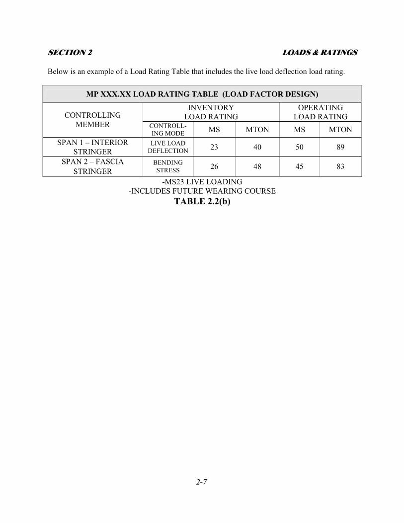
Below is an example of a Load Rating Table that includes the live load deflection load rating.
MP XXX.XX LOAD RATING TABLE (LOAD FACTOR DESIGN)
INVENTORY LOAD RATING
OPERATING LOAD RATING CONTROLLING
MEMBER CONTROLL-ING MODE MS MTON MS MTON
SPAN 1 – INTERIOR STRINGER
LIVE LOAD DEFLECTION 23 40 50 89
SPAN 2 – FASCIA STRINGER
BENDING STRESS 26 48 45 83
-MS23 LIVE LOADING -INCLUDES FUTURE WEARING COURSE
TABLE 2.2(b)

![Transport Engineering [Highway capacity and level of Web viewTransport Engineering [Highway capacity and level of service] Transport Engineering [Highway capacity and level of service]](https://img.pdfslide.us/doc/110x75/5a71dd367f8b9a9d538d33ba/transport-engineering-highway-capacity-and-level-of-nbspdoc-fileweb.jpg)