Embed Size (px)
Citation preview

Highway & Lead Local Flood Authority LINCOLNSHIRE DEVELOPMENT ROADS AND
SUSTAINABLE DRAINAGE DESIGN APPROACH November 2017 Edition
To be used in the Planning & Design of Development Roads & Sustainable Drainage Systems which are to become Highways maintainable at the public
expense.
Development Management Lincolnshire County Council Environment & Economy Directorate Lancaster House 36 Orchard Street LINCOLN LN1 1XX www.lincolnshire.gov.uk
© L.C.C.

November 2017 Issue
Forward
This Lincolnshire Development Roads and Sustainable Drainage Design Approach should be read in conjunction with the updated Lincolnshire Development Road and Sustainable Drainage Specification and Construction 2017 document.
This Development Design Approach aims to assist Developers to ensure that all new developments carried out within Lincolnshire do not have a detrimental effect on road safety and local flood risk, and where necessary, developer contributions are sought to facilitate the provision of a safe and multi-modal access to the development or transport infrastructure improvements.
The key objective of this approach is to link local policies, design principles, technical requirements and priorities with national policies. This Design Approach recognises the dual responsibilities of Lincolnshire County Council (LCC) as Highway Authority (HA) and Lead Local Flood Authority (LLFA) in the land use planning process and exercises these responsibilities in an integrated approach as Highway and Lead Local Flood Authority (HFA).
We aim to support all those involved in the development of new highways, related sustainable surface water drainage (SuDS) and the management of local flood risk (i.e. surface water, groundwater and from ordinary watercourses) across Lincolnshire, to help deliver exemplar developments in line with the latest Government requirements and industry best practice.
This design approach is a "living document" and we welcome your feedback and comments on its content and use. - Flood Risk & Development Manager, Highway & Lead Local Flood Authority, Lincolnshire County Council.
Introduction
Lincolnshire is a large rural County that has one of the fastest growing populations, rising much faster than regional and national rates. Lincolnshire's roads and infrastructure are very important to the County's economic development and well-being. Lincolnshire County Council (LCC) is both the Highway Authority (HA) and the Lead Local Flood Authority (LLFA).
As HA, it is a statutory consultee for all Planning Applications received by the District Councils and the County Council, whereas, as the LLFA it is responsible for local surface water flood risk management. This includes being a statutory consultee in the planning process for surface water management relating to Planning Applications for all Major Developments (i.e. 10 dwellings or more; or equivalent non-residential or mixed development). Sustainable Drainage Systems (SuDS) should be considered and implemented where appropriate. Combining these two responsibilities, the HFA responds to around 8,000 planning applications per annum. Officers within the HFA Development Management Team, based at LCC Offices in Lincoln carry out this function.
It is clear that in dealing with these applications, and in particular large commercial and residential sites, that the effect of increased traffic, increased surface water drainage and the potential increase in local flood risk generated by such developments, needs to be given careful consideration.
LCC welcomes and supports economic growth; in particular that which enriches the quality of life of its people. Developers will be required to ensure that such growth is not to the detriment of highway safety, disruption to the road network, and local flood risk. Indeed, they may be expected to contribute to improvements to the road, drainage and flood risk network to facilitate sustainable development proposals.
Forward &
Introduction
Page 2 of 54
November 2017 Issue
CONTENTS PAGE No
(Use hyperlinks)
1. Key National & Local Guidance ............................................................................. 6
2. Dealing with Planning Applications....................................................................... 7
3. Highway & SuDS Integrated Approach................................................................ 10
4. Assessing Transport Requirements.................................................................... 14
5. Design Approach for New Developments ........................................................... 16
6. Travel Plans........................................................................................................... 35
7. Parking Provision ................................................................................................. 35
8. Assessing Flood Risk........................................................................................... 44
9. Design through the Planning Process................................................................. 46
10. Highway & SuDS Agreements & Adoption.......................................................... 49
11. How to Contact Us ................................................................................................ 54
Table 2.1 - Example of key specific Flood Risk Assessment & SuDS requirements 8
Table 3.1 - Establishing infrastructure layout plans as part of the whole scheme design 10 process
Table 4.1 - Standard contents of a Transport Assessment 15
Table 5.1 - Indicative highway design parameters 18
Table 5.2 – Visibility Splays taken from Manual for Streets 24
Table 5.3 – Good SuDS design principles 25
Table 5.4 – LCC HFA flood and drainage criteria for highways and SuDS 27
Table 5.5 - Specific design requirements for filter drains and infiltration trenches 28
Table 5.6 - Specific design requirements for grass filter strips 29
Table 5.7 - Specific design requirements for pervious pavements 30
Table 5.8 - Specific design, construction and materials requirements for Swales and 30 Surface Water Flow Conveyance
Table 7.1 – Number of cycle stands for different types of development 37
Table 7.2 – Recommended parking requirements for different types of development 43
Table 8.1 -. Planning applications for which the HFA will respond on flood risk 44
Table 8.2 -. Planning applications for which the HFA require to a FRA or FRS to be able 44 to provide an informed response on flood risk
Table 8.3 - Indicative evidence based requirements, references and further information 45 required for a Local Sources FRA & FRS
Table 9.1 – Topic areas to be considered for “whole site scheme” design 46
Table 9.2 – Recommended combined process stages for planning & design 47
Table 9.3 – Likely design information required at Stage 1 - Pre-Application/Concept Design 47
Table 9.4 – Likely design information required at Stage 2 - Outline Application / Outline Design 48
Contents
Page 3 of 54

November 2017 Issue
Table 9.5 – Likely design information required at Stage 3 - Full Application / Approval of 48 Reserved Matters / Detailed Design
Table 10.1 – Scheme assets & relevant Adopting Authority 49
Table 10.2 - Drawings required to enable highway and SuDS assets to be considered for 51 adoption
Table 10.3 - Guidance on the contents of the SuDS Scheme Operation & Maintenance 52 Manual
Figure 2.1 - HFA secondary consultations 7
Figure 3.1 - Site characterisation 11
Figure 3.2 - Development characterisation 11
Figure 3.3 - Surface water sub-catchments and flow routes - including exceedance flows 12
Figure 3.4 - Conceptual design 12
Figure 5.1 – Typical local distributor road layout (elevation) 19
Figure 5.2 – Typical major access road layout (elevation) 20
Figure 5.3 – Typical minor access road/shared surfaces layout (elevation) 21
Figure 5.4 – Vertical visibility envelope (MfS) 23
Figure 5.5 – Typical sight lines at junctions (MfS) 23
Figure 5.6 - SuDS Management Train 26
Figure 5.7 – Cross-section of a typical filter drain 28
Figure 5.8 – Cross-section of a typical grass filter strip 29
Figure 5.9 – Cross-section of a typical pervious pavement 29
Figure 5.9.1 – Cross-section of a typical swale 30
Figure 5.9.2 – Use of root director material 33
Figure 5.9.3 – Use of the Arborflow system 33
Figure 7.1 – Typical parking layout for the disabled 39
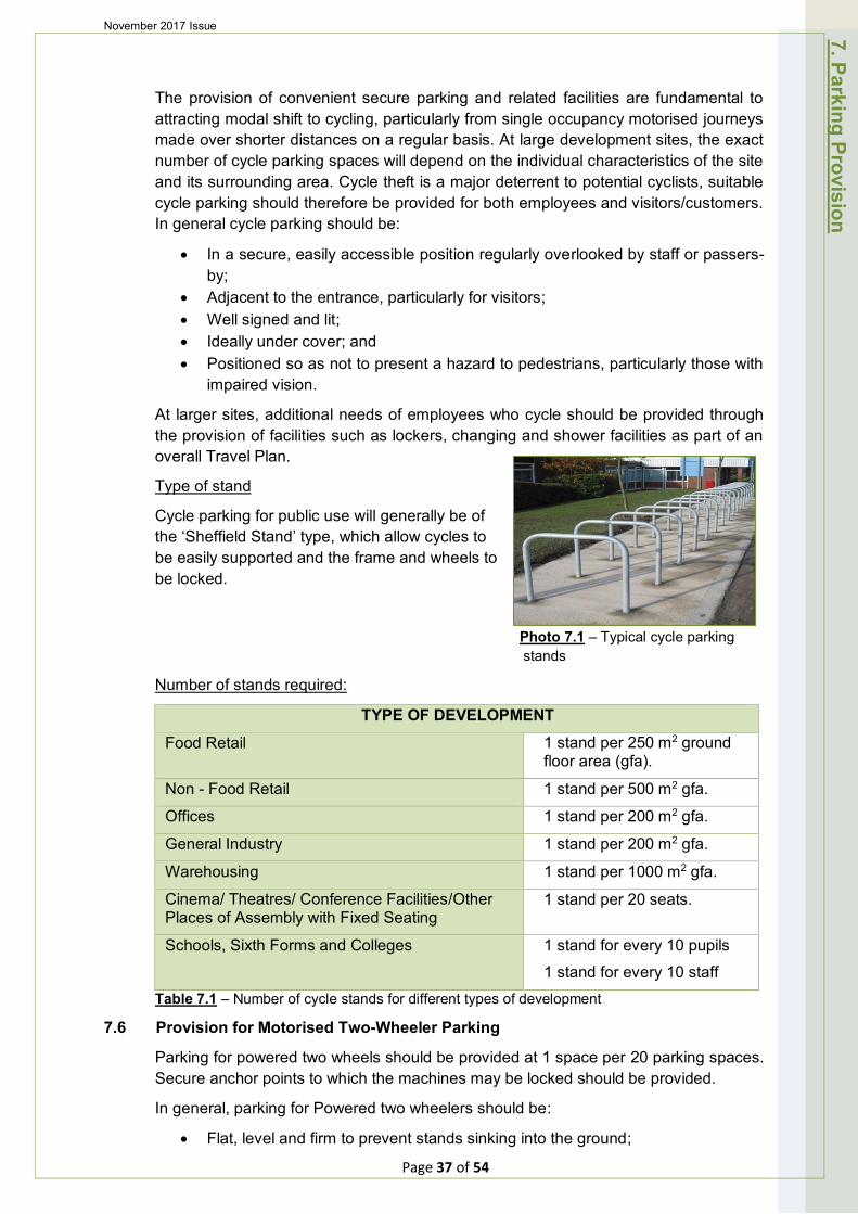
Figure 7.2 – Typical two-way flow parking layout 39
Figure 7.3 – Typical one-way flow 45-degree angled parking layout 40
Photo 5.1 – Typical local distributor road layout (plan view) 19
Photo 5.2 – Typical major access road layout (plan view) 20
Photo 5.3 – Typical minor access road/shared surfaces layout (plan view) 21
Photo 5.4 - Low lying fenland drain 25
Photo 5.5 – Typical filter drain 28
Photo 5.6 – Typical grass filter strip 29
Photo 5.7 – Typical pervious pavement 29
Photo 5.8 – Typical swale 30
Photo 7.1 – Typical cycle parking stands 37
Contents
Page 4 of 54
November 2017 Issue A
ppendices
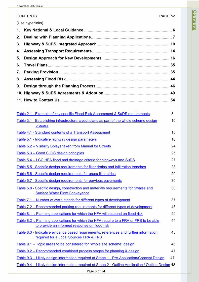
APPENDICES
A) SuDS Components and Indicative SuDS adopting Authority
B) Definition of MAJOR DEVELOPMENT & Links to Highways, Flood Risk, SuDS & Surface Water Drainage Technical Validation Check lists
• HFA Major Development Consultation Requirements & Check lists
C) Definition of MINOR “A” DEVELOPMENT & Links to Highways, Flood Risk, SuDS & Surface Water Drainage Technical Validation Check lists
• HFA Minor “A” Development Consultation Requirements & Check lists
D) Definition of MINOR “B” DEVELOPMENT & Links to Highways, Flood Risk, SuDS & Surface Water Drainage Technical Validation Check lists
• HFA Minor “B” Development Consultation Requirements & Check lists
E) - Further HFA Consultation Support Information & Check lists
F) First Contact with HFA - Planning Advice Service Form
G) Useful Guidance Documents
Page 5 of 54
November 2017 Issue
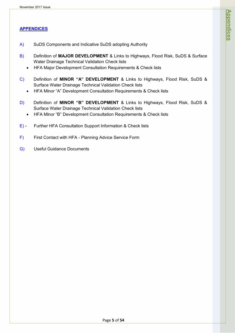
1. Key National & Local Guidance The following is a brief introduction to the main documents concerning transport, SuDS and local flood risk issues. Other useful guidance documents are listed in Appendix G.
1.1 National Planning Policy Framework (NPPF)
The framework acts as guidance for local planning authorities and decision-takers, both in drawing up plans and making decisions about planning applications. This Policy Framework must be taken into account in the preparation of local and neighbourhood plans, and is a material consideration in planning decisions.
1.2 Planning Practice Guidance (PPG)
The Guidance supports the NPPF and contains more detailed useful information on a range of development related topics including climate change, design, SuDS, flood risk assessment, environment, housing, transport and travel assessments etc.
1.3 Local Plans
Local Plans are the responsibility of the Local Planning Authority who should be contacted at the earliest stage in the planning process. Local Plan documents set out the strategic priorities for development of an area. With regard to the interests of the HFA, Local Plans will include policies to deliver: housing, retail, leisure and other commercial development; infrastructure for transport, water supply, sewage treatment, surface water drainage; and protection of homes and property from flooding from rivers and the sea.
1.4 Manual for Streets (MfS)
Published by the Government, it replaces Design Bulletin 32 and ‘Places Streets and Movement’. It focuses mainly on residential streets and putting well-designed streets at the heart of sustainable communities. Amongst other things, it updates the link between planning policy and street design; includes revised design guidance; and places strong emphasis on a coordinated design approach. Supplementary guidance is also provided in Manual for Streets 2.
1.5 Sustainable Drainage Systems (SuDS) Manual - (CIRIA C753)
The Guidance covers the planning, design, construction and maintenance of SuDS to assist with their effective implementation within both new and existing developments. It is a compendium of good practice, based on existing guidance and research, and provides a framework for designing sustainable drainage.
1.6 Lincolnshire Development Road and Sustainable Drainage Specification and Construction (DR&SDS&C)
This recently updated document provides the HFA's detailed specification, standards and requirements for materials, construction and maintenance of roads and sustainable drainage necessary to enable adoption as public highway and features, and maintainable at public expense.
1.7 Development and Flood Risk Guidance for the Construction Industry – (CIRIA 624)
The document provides guidance to Developers and the construction industry on the implementation of good practice in the assessment and management of flood risk as part of the development process, and is intended to promote development that is sustainable in terms of flood risk.
1. Key N
ational & Local G
uidance
Page 6 of 54
November 2017 Issue
Page 7 of 54
2. Dealing with Planning Applications 2.1 Early Discussion on Highway, Drainage and Flood Risk Infrastructure
Principles and Strategic Objectives
The planning application process and the HFA highway and drainage adoption process are inextricably linked. Therefore, all highway, drainage and flood risk infrastructure principles and strategic objectives should be discussed with the HFA at the earliest possible stage in the development design process. In the first instance, developers are requested to contact the HFA for an initial discussion prior to formal pre-planning and pre-adoption application discussions being made through the LPA. A “First Contact with HFA -Planning Advice Service Form” should be used and is provided in Appendix F.
2.2 Response to Planning Applications
The HFA will provide an integrated response (i.e. highways, SuDS and local flood risk) to the LPA at all stages of the land use planning process.
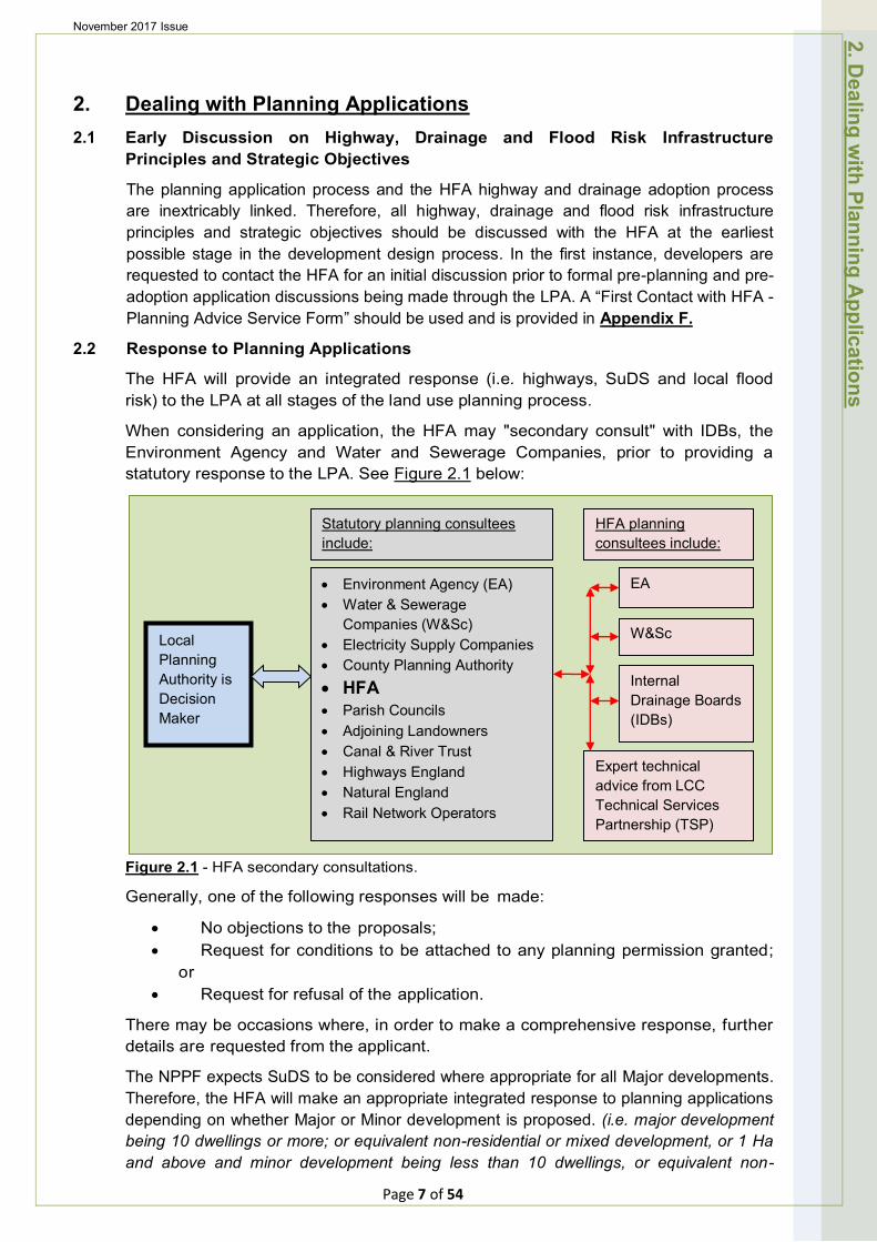
When considering an application, the HFA may "secondary consult" with IDBs, the Environment Agency and Water and Sewerage Companies, prior to providing a statutory response to the LPA. See Figure 2.1 below:
Figure 2.1 - HFA secondary consultations.
Generally, one of the following responses will be made:
• No objections to the proposals; • Request for conditions to be attached to any planning permission granted;
or • Request for refusal of the application.
There may be occasions where, in order to make a comprehensive response, further details are requested from the applicant.
The NPPF expects SuDS to be considered where appropriate for all Major developments. Therefore, the HFA will make an appropriate integrated response to planning applications depending on whether Major or Minor development is proposed. (i.e. major development being 10 dwellings or more; or equivalent non-residential or mixed development, or 1 Ha and above and minor development being less than 10 dwellings, or equivalent non-
2. Dealing w
ith Planning Applications
Local Planning Authority is Decision Maker
• Environment Agency (EA) • Water & Sewerage
Companies (W&Sc) • Electricity Supply Companies • County Planning Authority • HFA • Parish Councils • Adjoining Landowners • Canal & River Trust • Highways England • Natural England • Rail Network Operators
EA
W&Sc
Internal Drainage Boards (IDBs)
Expert technical advice from LCC Technical Services Partnership (TSP)
Statutory planning consultees include:
HFA planning consultees include:

November 2017 Issue
residential or mixed development, or below 1 Ha).
Information on the HFA's specific planning and adoption milestones, along with the requirements at each stage, is provided in Appendices B, C, D & F. These list the essential technical documents and information required at various stages of the planning process to enable the necessary HFA work to be progressed. By way of example, key specific flood risk assessment & SuDS requirements include the following:
Site specific FLOOD RISK Where "Major development" is proposed ASSESSMENT (FRA) and/or development is within an identified
1:100y Surface Water and/or Groundwater Flood Risk Area (viewed using EA website).
Site specific FLOOD RISK STATEMENT Where "Minor development" is proposed (FRS) and/or within an identified 1:100y Surface
Water and/or Groundwater Flood Risk Area (viewed using EA website).
Site specific DRAINAGE STRATEGY (DS)
Where "Major development" is proposed.
Site specific DEVELOPMENT CONSTRUCTION MANAGEMENT PLAN
Where "Major development" incorporating a proposed HFA adopted SuDS solution is proposed.
Table 2.1 – Example of key specific Flood Risk Assessment & SuDS requirements
The extent of detail of the information provided should be appropriate to the size and complexity of the proposed development, and in addition to reference to Appendices B, C, D & E; further guidance can be provided by the HFA Development Management Team.
2.3 Planning Conditions - Definition
The HFA in reviewing development proposals will consider whether otherwise unacceptable development could be made acceptable through the use of conditions or planning obligations. Planning obligations should only be used where it is not possible to address unacceptable impacts through a planning condition.
Section 106 Contributions (Planning obligations) will only be sought where they meet all of the following tests:
● necessary to make the development acceptable in planning terms;
● directly related to the development; and
● fairly and reasonably related in scale and kind, to the development.
Planning conditions will only be requested where they are necessary, relevant to planning and to the development to be permitted, enforceable, precise and reasonable in all other respects.
2.4 Refusals
Where the HFA considers the residual cumulative transport impacts of development are severe, it will request the planning authority to refuse an application on one of more of the following grounds: (See Para 32, NPPF.)
• Significant amounts of transport movement is not supported by a Transport Statement or Transport Assessment;
• Opportunities for sustainable transport modes have not been taken up depending on the nature and location of the site, so reducing the need for major transport infrastructure;
• Safe and suitable access to the site cannot be achieved for all people; and
Page 8 of 54
2. Dealing w
ith Planning Applications
November 2017 Issue
• Improvements cannot be undertaken within the transport network that cost effectively limits the significant impacts of the development.
Where the HFA considers highway drainage not to be sustainable, and/or where local flood risk has not been appropriately taken into account and mitigated, it will request the planning authority to refuse an application.
2.5 Appeals
When an application has been refused the applicant has the right to appeal to the Secretary of State. The appeal can be dealt with in three different ways:
Written Representation - each side provides a written statement to the Planning Inspectorate; Informal Hearing - written evidence is submitted to the Inspectorate, who arranges a hearing, attended by an Inspector. Both sides present their evidence and are given the opportunity to discuss the merits of each side's arguments. A site visit may be made. The Inspector writes to each side with the formal decision; and Public Inquiry - similar to the informal hearing except that the evidence is presented formally and tested by cross-examination. Each side usually has legal representation. Members of the public who have made representations on the application are also allowed to give evidence.
2. Dealing w
ith Planning Applications
Page 9 of 54
November 2017 Issue
3. Highway & SuDS Integrated Approach
3.1 Integrated Approach
The HFA will work closely with Developers and LPAs to achieve an integrated overall design approach to all new development. Early consideration of infrastructure requirements to serve the development is essential, and close discussion with relevant infrastructure service providers is recommended to guide integrated infrastructure planning and provision.
3.2 Principles and Strategic Objectives of Development
In addition to the Developer's overall objective of providing a building or structure on the site that delivers the intended use, specific integrated principles and strategic objectives relating to highways, sustainable drainage and local flood risk infrastructure need to be agreed with the HFA at the outset. In any new development it is important that the drainage of the site, including taking account of extreme weather events, is considered as early as possible in the design process.
3.3 Integrated Concept
Traditionally, highway drainage and local flood risk have, in many cases, been a secondary consideration when determining the development site layout, number and type of buildings. This has led to some built developments with inadequate space and sited in inappropriate locations, with insufficient areas of land remaining for essential infrastructure. However, with the Governments requirement for SuDS for the management of run-off for all Major developments, this traditional approach, particularly regarding highways, drainage and local flood risk infrastructure is no longer appropriate. For further information see the updated SuDS Manual (C753): Appendix C, Design Example Rosetree Estate
The distribution and layout of buildings on a site can greatly influence the potential for creating flood pathways and affect flood risk to property. The integrated Concept is the first of four stages of integrated design and construction:
1) Concept;
2) Outline;
3) Detailed; and
4) Adoption.
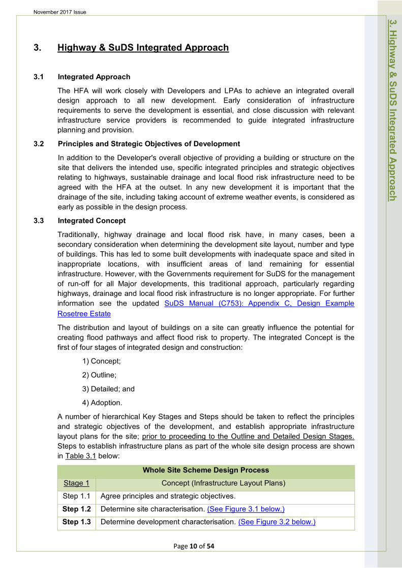
A number of hierarchical Key Stages and Steps should be taken to reflect the principles and strategic objectives of the development, and establish appropriate infrastructure layout plans for the site; prior to proceeding to the Outline and Detailed Design Stages. Steps to establish infrastructure plans as part of the whole site design process are shown in Table 3.1 below:
Whole Site Scheme Design Process
Stage 1 Concept (Infrastructure Layout Plans)
Step 1.1 Agree principles and strategic objectives.
Step 1.2 Determine site characterisation. (See Figure 3.1 below.)
Step 1.3 Determine development characterisation. (See Figure 3.2 below.)
3. Highw
ay & SuD
S Integrated A
pproach
Page 10 of 54
November 2017 Issue
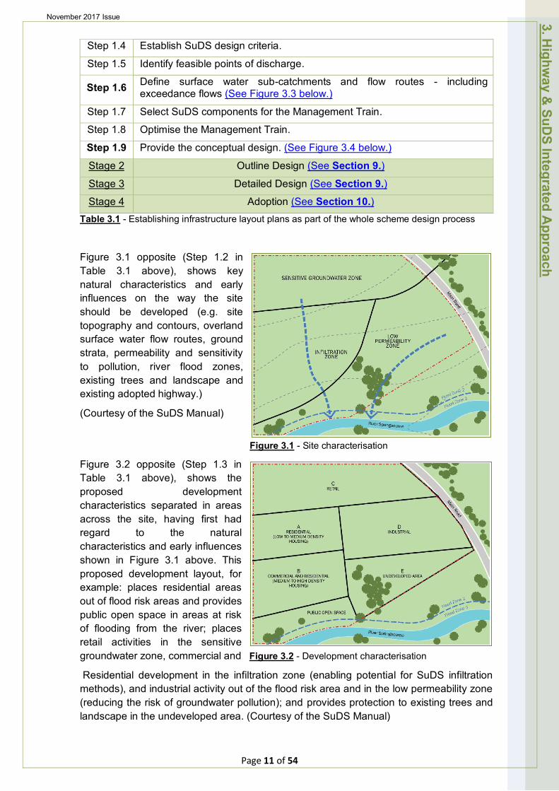
Step 1.4 Establish SuDS design criteria.
Step 1.5 Identify feasible points of discharge.
Step 1.6 Define surface water sub-catchments and flow routes - including exceedance flows (See Figure 3.3 below.)
Step 1.7 Select SuDS components for the Management Train.
Step 1.8 Optimise the Management Train.
Step 1.9 Provide the conceptual design. (See Figure 3.4 below.)
Stage 2 Outline Design (See Section 9.)
Stage 3 Detailed Design (See Section 9.) Stage 4 Adoption (See Section 10.)
Table 3.1 - Establishing infrastructure layout plans as part of the whole scheme design process
Figure 3.1 opposite (Step 1.2 in Table 3.1 above), shows key natural characteristics and early influences on the way the site should be developed (e.g. site topography and contours, overland surface water flow routes, ground strata, permeability and sensitivity to pollution, river flood zones, existing trees and landscape and existing adopted highway.)
(Courtesy of the SuDS Manual)
Figure 3.1 - Site characterisation
Figure 3.2 opposite (Step 1.3 in Table 3.1 above), shows the proposed development characteristics separated in areas across the site, having first had regard to the natural characteristics and early influences shown in Figure 3.1 above. This proposed development layout, for example: places residential areas out of flood risk areas and provides public open space in areas at risk of flooding from the river; places retail activities in the sensitive groundwater zone, commercial and Figure 3.2 - Development characterisation
Residential development in the infiltration zone (enabling potential for SuDS infiltration methods), and industrial activity out of the flood risk area and in the low permeability zone (reducing the risk of groundwater pollution); and provides protection to existing trees and landscape in the undeveloped area. (Courtesy of the SuDS Manual)
3. Highw
ay & SuD
S Integrated A
pproach
Page 11 of 54
November 2017 Issue
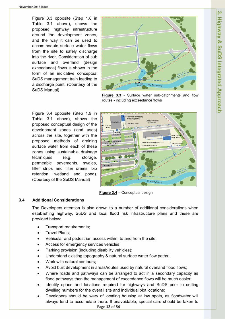
Figure 3.3 opposite (Step 1.6 in Table 3.1 above), shows the proposed highway infrastructure around the development zones, and the way it can be used to accommodate surface water flows from the site to safely discharge into the river. Consideration of sub surface and overland (design exceedance) flows is shown in the form of an indicative conceptual SuDS management train leading to a discharge point. (Courtesy of the SuDS Manual)
Figure 3.3 - Surface water sub-catchments and flow routes - including exceedance flows
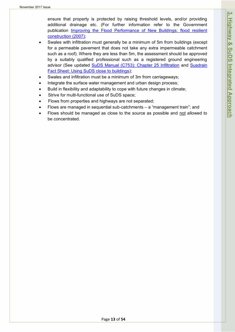
Figure 3.4 opposite (Step 1.9 in Table 3.1 above), shows the proposed conceptual design of the development zones (land uses) across the site, together with the proposed methods of draining surface water from each of these zones using sustainable drainage techniques (e.g. storage, permeable pavements, swales, filter strips and filter drains, bio retention, wetland and pond). (Courtesy of the SuDS Manual)
Figure 3.4 – Conceptual design
3.4 Additional Considerations
The Developers attention is also drawn to a number of additional considerations when establishing highway, SuDS and local flood risk infrastructure plans and these are provided below:
• Transport requirements; • Travel Plans; • Vehicular and pedestrian access within, to and from the site; • Access for emergency services vehicles; • Parking provision (including disability vehicles); • Understand existing topography & natural surface water flow paths; • Work with natural contours; • Avoid built development in areas/routes used by natural overland flood flows; • Where roads and pathways can be arranged to act in a secondary capacity as
flood pathways then the management of exceedance flows will be much easier; • Identify space and locations required for highways and SuDS prior to setting
dwelling numbers for the overall site and individual plot locations; • Developers should be wary of locating housing at low spots, as floodwater will
always tend to accumulate there. If unavoidable, special care should be taken to Page 12 of 54
3. Highw
ay & SuD
S Integrated A
pproach
November 2017 Issue
ensure that property is protected by raising threshold levels, and/or providing additional drainage etc. (For further information refer to the Government publication Improving the Flood Performance of New Buildings: flood resilient construction (2007);
• Swales with infiltration must generally be a minimum of 5m from buildings (except for a permeable pavement that does not take any extra impermeable catchment such as a roof). Where they are less than 5m, the assessment should be approved by a suitably qualified professional such as a registered ground engineering advisor (See updated SuDS Manual (C753): Chapter 25 Infiltration and Susdrain Fact Sheet: Using SuDS close to buildings);
• Swales and infiltration must be a minimum of 3m from carriageways; • Integrate the surface water management and urban design process; • Build in flexibility and adaptability to cope with future changes in climate; • Strive for multi-functional use of SuDS space; • Flows from properties and highways are not separated; • Flows are managed in sequential sub-catchments – a “management train”; and • Flows should be managed as close to the source as possible and not allowed to
be concentrated.
3. Highw
ay & SuD
S Integrated A
pproach
Page 13 of 54
November 2017 Issue
4. Assessing Transport Requirements 4.1 Approach
LCC will review development proposals in accordance with National Planning Policy Guidance. Developments which generate significant amounts of movements should be supported by a Transport Assessment.
• Opportunities for sustainable modes should be taken up; • Safe and suitable access for all should be achieved; and • The residual cumulative impact of the development should not be severe.
4.2 Guidance for Where Transport Assessments may be Required
Transport Assessments will be required for all large developments, typically: • 80 or more dwellings; • 1000 sq. m. and above GFA retail; • 2500 sq. m. and above GFA office; • 5000 sq. m. and above GFA industry; and • 10000 sq. m. and above GFA warehousing.
Other development uses need to be considered on an individual basis. Smaller developments which generate less traffic, still need to demonstrate that NPPF transport objectives have been achieved and a Transport Statement may be required.
4.3 Scope of a Transport Assessment
The detailed scope of a Transport Assessment should be discussed and agreed with the HFA Development Management Officer, prior to preparation and submission in support of a development proposal. In principle Transport Assessments and Statements should:
• Be proportionate to the size and scope of the proposed development to which they relate and build on existing information wherever possible;
• Be established at the earliest possible practicable stage of a development proposal;
• Be tailored to particular local circumstances, (other locally-determined factors and information may need to be considered in these studies provided there is robust evidence for doing so locally);
• Be brought forward through collaborative ongoing working between the Local Planning Authority/Transport Authority, transport operators, Rail Network Operators, Highways England (where there may be implications for the strategic road network) and other relevant bodies; and
• Refer to, and where necessary, use output from existing transport models which the HFA maintain and operate for the larger urban centres in the County.
Transport Assessments and Transport Statements should primarily focus on evaluating the potential transport impacts of a development proposal. They may consider those impacts net of any reductions likely to arise from the implementation of a Travel Plan, though producing a Travel Plan is not always required. The Transport Assessment or Transport Statement may propose mitigation measures where these are necessary to avoid unacceptable or “severe” impacts. Travel Plans can play an effective role in taking forward those mitigation measures which relate to on-going occupation and operation of the development.
4. Assessing Transport R
equirements
Page 14 of 54
November 2017 Issue
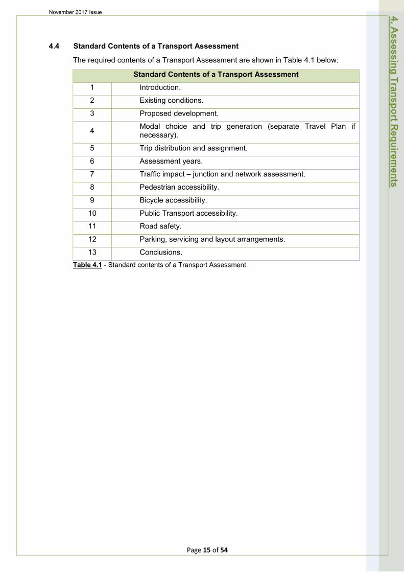
4.4 Standard Contents of a Transport Assessment
The required contents of a Transport Assessment are shown in Table 4.1 below:
Standard Contents of a Transport Assessment
1 Introduction.
2 Existing conditions.
3 Proposed development.
4 Modal choice and trip generation (separate Travel Plan if necessary).
5 Trip distribution and assignment.
6 Assessment years.
7 Traffic impact – junction and network assessment.
8 Pedestrian accessibility.
9 Bicycle accessibility.
10 Public Transport accessibility.
11 Road safety.
12 Parking, servicing and layout arrangements.
13 Conclusions. Table 4.1 - Standard contents of a Transport Assessment
4. Assessing Transport R
equirements
Page 15 of 54
November 2017 Issue
5. Design Approach for New Developments
5.1 Published Guidance
The County Council, in conjunction with the District Councils, as local planning authorities, seek to promote good quality developments that provide a safe and pleasant environment. New developments should provide residents, where possible, with access to a choice of modes of transport.
All new residential developments should take on board the guidance provided in this document. It aims to give developers guidance on how to achieve a better residential environment for their customers. One of the key factors in producing a good design is the preparation of a design brief for the site. Further information on design considerations is provided in Manual for Streets (MfS) and the SuDS Manual, Chapter 9 - Designing for Roads and Highways. Together with this Design Approach, these documents should form the primary source of design guidance for developers; this chapter aims to provide examples of the application of this guidance.
Guidance on the construction of both residential and industrial estate roads can be found in the HFA Development Road and Sustainable Drainage Specification and Construction document.
5.2 Design Considerations
Highway designs should reflect the anticipated pedestrian, cycle and vehicle usage whilst ensuring that speeds are kept low and traffic is not encouraged to use new estates as through routes. It should be remembered that streets should be designed to allow social interaction, encourage all modes and not just the free flow of traffic. Consideration should be given to ensure adequate facilities are provided to enable residents of new estates to gain easy access to essential services. Information and advice on the design principles for highways, sustainable drainage and flood risk mitigation should be sought from the HFA at the earliest opportunity.
Particular attention will need to be given to the following:
Walking and Cycling
It is important that designs reflect adequately the needs of pedestrians and cyclists. Consideration should be given to the circumstances in which residents will need to walk/cycle to schools, shops, doctors, bus stops etc. The use of separate footway and/or cycle links into/out of estates are encouraged and indeed will generally be required on cul-de-sacs over 200m in length.
It is important when designing new residential estates, sufficient provision is made for pedestrians and cyclists by the creation of safe, direct and secure routes along with any necessary facilities.
Inclusive Mobility
It is important that new developments do not put up barriers to any sections of the community. Care must be taken when designing new estates to ensure adequate access and facilities are provided for all. Pedestrian crossings at junctions should
5. Design A
pproach for New
Developm
ents
Page 16 of 54
November 2017 Issue
be located in the most convenient location that does not expose the users to dangers from vehicular traffic.
Developers are recommended to refer to the Department for Transport's document "Inclusive Mobility A Guide to Best Practice on Access to Pedestrian and Transport Infrastructure."
Public Transport
In all new residential developments, the potential for improved public transport accessibility needs to be assessed, whether this is through direct access or via links to the existing network. Pedestrian and cycle links to public transport facilities which are safe, secure and well-lit may be required as part of the new development.
Drainage
Unless otherwise indicated in this document, all new highway drainage systems must be designed in accordance with the appropriate guidance. These include Design Manual for Roads and Bridges (DMRB), Manual for Streets (MfS), Practice Guidance on Defra's Non Statutory Technical Standards for Sustainable Drainage (LASOO) and the SuDS Manual (C753).
Sustainable drainage principles should be incorporated in all developments as a requirement of both the planning process and the highway and SuDS adoption process. Surface water drainage infrastructure should be designed as an integral part of the highway system and a "whole site" scheme design approach adopted at each of the first three key stages of design and construction referred to previously in Table 3.1:
1) Concept;
2) Outline; and
3) Detailed.
The provision of SuDS should be considered prior to fixing the total number of building plots and any plot locations. Good SuDS principles should be adopted by maximising the use of natural contours, topography and geology of the development site; and the benefits these can bring to the location, routing, layout and type of SuDS and highways infrastructure; together with considering dual use of areas such as open space and those set aside for amenity purposes.
Where it is necessary for rainwater from private residential property to drain to the highway drainage system, the HFA will consider accepting these flows as part of an integrated system. Retrofitting SuDS on new development sites is likely to result in poor solutions which are unlikely to be approved or adopted by the HFA. The HFA will require evidence that the sewerage undertakers have adopted surface and foul water sewers before it will adopt the roads and footways.
5.3 Highway Design
Typical residential estates should have a clear road hierarchy with routes designed to accommodate the expected users. Principal routes in large estates will likely be designed to accommodate bus routes. Secondary routes will provide connections and need segregated footways due to expected vehicle flows, whilst minor access routes will be able to be designed as shared surfaces (shared space) for all road users – pedestrians, cyclists and vehicles.
5. Design A
pproach for New
Developm
ents
Page 17 of 54
November 2017 Issue
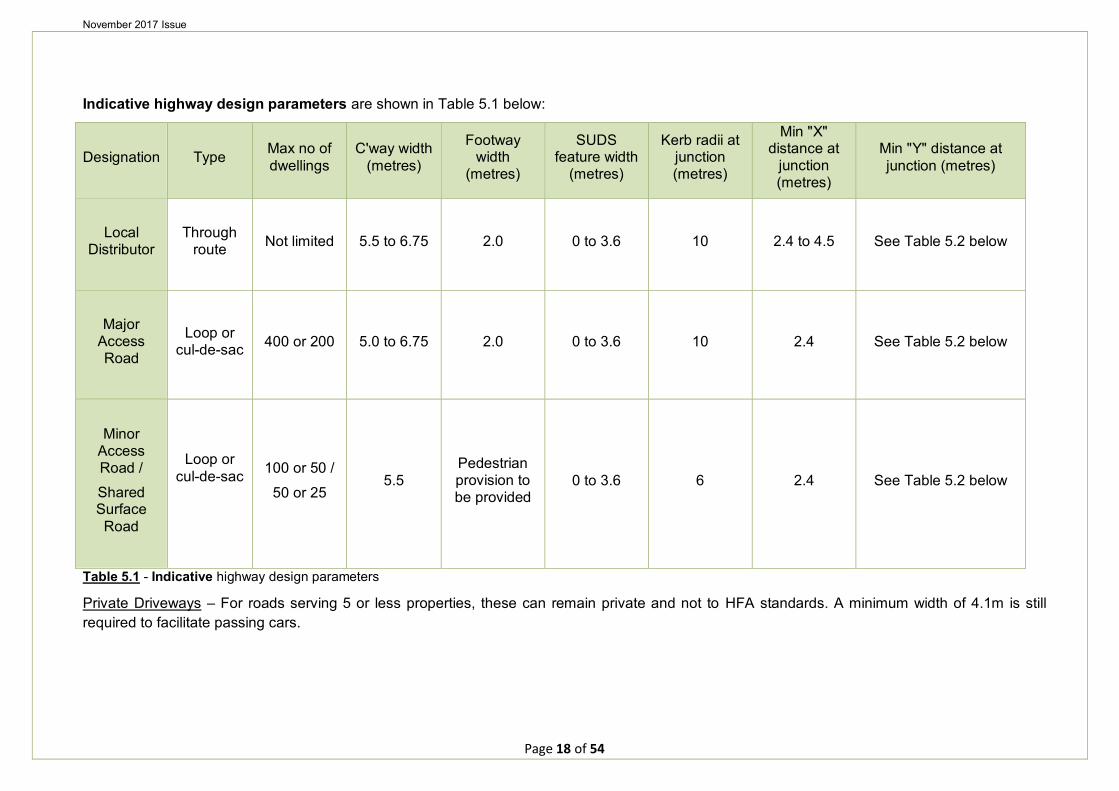
Indicative highway design parameters are shown in Table 5.1 below:
Designation Type Max no of dwellings
C'way width (metres)
Footway width
(metres)
SUDS feature width
(metres)
Kerb radii at junction (metres)
Min "X" distance at
junction (metres)
Min "Y" distance at junction (metres)
Local Distributor
Through route Not limited 5.5 to 6.75 2.0 0 to 3.6 10 2.4 to 4.5 See Table 5.2 below
Major Access Road
Loop or cul-de-sac 400 or 200 5.0 to 6.75 2.0 0 to 3.6 10 2.4 See Table 5.2 below
Minor Access Road /
Shared Surface Road
Loop or cul-de-sac 100 or 50 /
50 or 25 5.5
Pedestrian provision to be provided
0 to 3.6 6 2.4 See Table 5.2 below
Table 5.1 - Indicative highway design parameters
Private Driveways – For roads serving 5 or less properties, these can remain private and not to HFA standards. A minimum width of 4.1m is still required to facilitate passing cars.
Page 18 of 54
November 2017 Issue
Typical Highway Examples
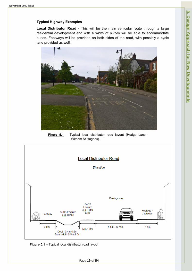
Local Distributor Road - This will be the main vehicular route through a large residential development and with a width of 6.75m will be able to accommodate buses. Footways will be provided on both sides of the road, with possibly a cycle lane provided as well.
Photo 5.1 – Typical local distributor road layout (Hedge Lane, Witham St Hughes).
5. Design A
pproach for New
Developm
ents
Figure 5.1 – Typical local distributor road layout
Page 19 of 54
November 2017 Issue
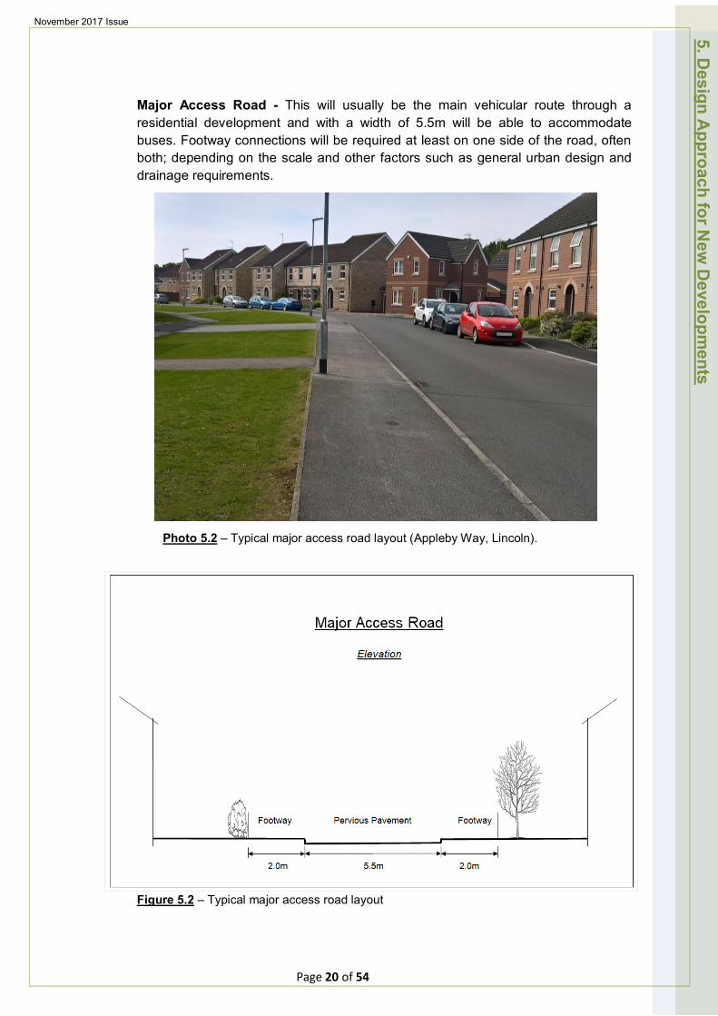
Major Access Road - This will usually be the main vehicular route through a residential development and with a width of 5.5m will be able to accommodate buses. Footway connections will be required at least on one side of the road, often both; depending on the scale and other factors such as general urban design and drainage requirements.
Photo 5.2 – Typical major access road layout (Appleby Way, Lincoln).
5. Design A
pproach for New
Developm
ents
Figure 5.2 – Typical major access road layout
Page 20 of 54
November 2017 Issue
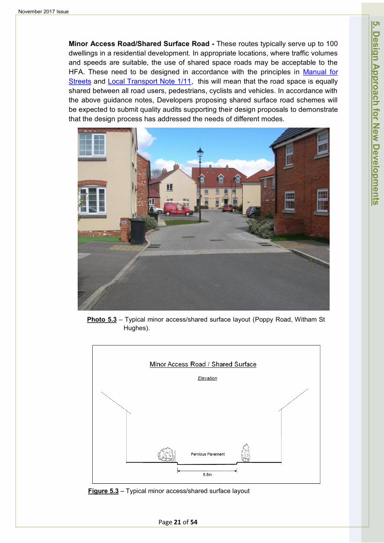
Minor Access Road/Shared Surface Road - These routes typically serve up to 100 dwellings in a residential development. In appropriate locations, where traffic volumes and speeds are suitable, the use of shared space roads may be acceptable to the HFA. These need to be designed in accordance with the principles in Manual for Streets and Local Transport Note 1/11, this will mean that the road space is equally shared between all road users, pedestrians, cyclists and vehicles. In accordance with the above guidance notes, Developers proposing shared surface road schemes will be expected to submit quality audits supporting their design proposals to demonstrate that the design process has addressed the needs of different modes.
Photo 5.3 – Typical minor access/shared surface layout (Poppy Road, Witham St Hughes).
5. Design A
pproach for New
Developm
ents
Figure 5.3 – Typical minor access/shared surface layout
Page 21 of 54
November 2017 Issue
Speed Restraint
Low traffic speeds can be achieved through good horizontal design features. Several design measures can be employed to ensure vehicle speeds are reduced as follows:
Junctions
The use of junctions on residential roads can disrupt the flow of vehicles through estates and thereby keep speeds low. More frequent junctions and reduced lengths of straight roads will encourage low speeds and more careful movement of traffic. Tighter radii at internal junctions, as opposed to wide sweeping curves, will also ensure vehicle speeds are reduced.
Bends
The use of tighter bends on major and minor residential roads will control speed. Widening, as specified above, may be required for larger vehicles.
The removal of forward visibility splays on bends (where deemed appropriate, by the HFA) will also help. Developers will however; be required to demonstrate the movement of vehicles by the use of swept paths.
Reduced Lengths of Straights
In order to achieve low design speeds, the lengths of straight sections of carriageway should be kept to a minimum. For example: by restricting straight lengths of road to a maximum length of 60m, 85 percentile speeds of 20 mph will be achieved.
Widths
On minor residential roads the width can be varied to help reduce speeds. Wider sections should however be used at junctions.
Gradients.
Where a new estate road junction is formed within an existing carriageway the gradient of the new estate road carriageway shall not normally be steeper than 1 in 40 for a distance of 20 metres from the nearside edge of the existing carriageway from which the level is taken; not normally steeper than 1 in 20 for a further 30 metres and thereafter not normally steeper than 1 in 15.
Channel blocks will be required where the carriageway longitudinal gradient is less than 1 in 150, and the channel blocks will need to be laid to 'false falls' where the longitudinal gradient is less than 1 in 250. The minimum longitudinal gradient for block paved roads is 1 in 150.
Visibility at Junctions
It is important to provide adequate sightlines at junctions (see Figure 5.4 & Figure 5.5 below), to provide safe access and egress of vehicles in accordance with Manual for Streets (MfS). All land within specified visibility splays at junctions will need to be within existing highway limits or within the developers control to ensure it can be dedicated as publicly maintainable highway on the adoption of the estate roads.
5. Design A
pproach for New
Developm
ents
Page 22 of 54
November 2017 Issue
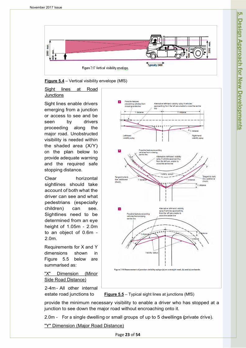
Figure 5.4 – Vertical visibility envelope (MfS)
Sight lines at Road Junctions
Sight lines enable drivers emerging from a junction or access to see and be seen by drivers proceeding along the major road. Unobstructed visibility is needed within the shaded area (X/Y) on the plan below to provide adequate warning and the required safe stopping distance.
Clear horizontal sightlines should take account of both what the driver can see and what pedestrians (especially children) can see. Sightlines need to be determined from an eye height of 1.05m - 2.0m to an object of 0.6m -2.0m.
Requirements for X and Y dimensions shown in Figure 5.5 below are summarised as:
"X" Dimension (Minor Side Road Distance)
2-4m - All other internal estate road junctions to Figure 5.5 – Typical sight lines at junctions (MfS)
provide the minimum necessary visibility to enable a driver who has stopped at a junction to see down the major road without encroaching onto it.
2.0m - For a single dwelling or small groups of up to 5 dwellings (private drive).
"Y" Dimension (Major Road Distance)
5. Design A
pproach for New
Developm
ents
Page 23 of 54
November 2017 Issue
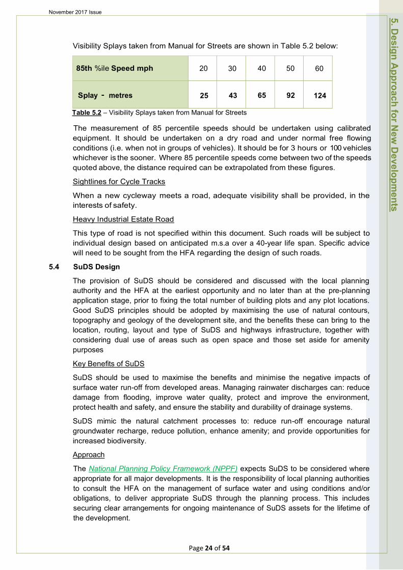
Visibility Splays taken from Manual for Streets are shown in Table 5.2 below:
85th %ile Speed mph 20 30 40 50 60
Splay · metres 25 43 65 92 124
Table 5.2 – Visibility Splays taken from Manual for Streets
The measurement of 85 percentile speeds should be undertaken using calibrated equipment. It should be undertaken on a dry road and under normal free flowing conditions (i.e. when not in groups of vehicles). It should be for 3 hours or 100 vehicles whichever is the sooner. Where 85 percentile speeds come between two of the speeds quoted above, the distance required can be extrapolated from these figures.
Sightlines for Cycle Tracks
When a new cycleway meets a road, adequate visibility shall be provided, in the interests of safety.
Heavy Industrial Estate Road
This type of road is not specified within this document. Such roads will be subject to individual design based on anticipated m.s.a over a 40-year life span. Specific advice will need to be sought from the HFA regarding the design of such roads.
5.4 SuDS Design
The provision of SuDS should be considered and discussed with the local planning authority and the HFA at the earliest opportunity and no later than at the pre-planning application stage, prior to fixing the total number of building plots and any plot locations. Good SuDS principles should be adopted by maximising the use of natural contours, topography and geology of the development site, and the benefits these can bring to the location, routing, layout and type of SuDS and highways infrastructure, together with considering dual use of areas such as open space and those set aside for amenity purposes
Key Benefits of SuDS
SuDS should be used to maximise the benefits and minimise the negative impacts of surface water run-off from developed areas. Managing rainwater discharges can: reduce damage from flooding, improve water quality, protect and improve the environment, protect health and safety, and ensure the stability and durability of drainage systems.
SuDS mimic the natural catchment processes to: reduce run-off encourage natural groundwater recharge, reduce pollution, enhance amenity; and provide opportunities for increased biodiversity.
Approach
The National Planning Policy Framework (NPPF) expects SuDS to be considered where appropriate for all major developments. It is the responsibility of local planning authorities to consult the HFA on the management of surface water and using conditions and/or obligations, to deliver appropriate SuDS through the planning process. This includes securing clear arrangements for ongoing maintenance of SuDS assets for the lifetime of the development.
5. Design A
pproach for New
Developm
ents
Page 24 of 54
November 2017 Issue
The Government Department for Food and Rural Affairs (DEFRA) produced Non-statutory technical standards for SuDS in March 2015 for the design, maintenance and operation of SuDS and these should be adhered to.
Unless otherwise stated, and in conjunction with this Design Approach, the SuDS Manual (C753) should be used to guide the assessment of sustainable drainage requirements for each development proposal.
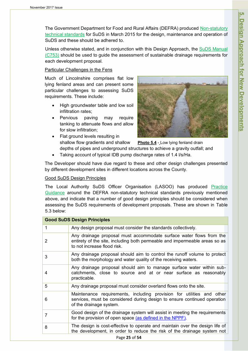
Particular Challenges in the Fens
Much of Lincolnshire comprises flat low lying fenland areas and can present some particular challenges to assessing SuDS requirements. These include:
• High groundwater table and low soil infiltration rates;
• Pervious paving may require tanking to attenuate flows and allow for slow infiltration;
• Flat ground levels resulting in shallow flow gradients and shallow Photo 5.4 - Low lying fenland drain depths of pipes and underground structures to achieve a gravity outfall; and
• Taking account of typical IDB pump discharge rates of 1.4 l/s/Ha.
The Developer should have due regard to these and other design challenges presented by different development sites in different locations across the County.
Good SuDS Design Principles
The Local Authority SuDS Officer Organisation (LASOO) has produced Practice Guidance around the DEFRA non-statutory technical standards previously mentioned above, and indicate that a number of good design principles should be considered when assessing the SuDS requirements of development proposals. These are shown in Table 5.3 below:
Good SuDS Design Principles
1 Any design proposal must consider the standards collectively.
2 Any drainage proposal must accommodate surface water flows from the entirety of the site, including both permeable and impermeable areas so as to not increase flood risk.
3 Any drainage proposal should aim to control the runoff volume to protect both the morphology and water quality of the receiving waters.
4 Any drainage proposal should aim to manage surface water within sub-catchments, close to source and at or near surface as reasonably practicable.
5 Any drainage proposal must consider overland flows onto the site.
6 Maintenance requirements, including provision for utilities and other services, must be considered during design to ensure continued operation of the drainage system.
7 Good design of the drainage system will assist in meeting the requirements for the provision of open space (as defined in the NPPF).
8 The design is cost-effective to operate and maintain over the design life of the development, in order to reduce the risk of the drainage system not
5. Design A
pproach for New
Developm
ents
Page 25 of 54

November 2017 Issue
functioning.
9
The design of the drainage systems must account for the likely impacts of climate change; and changes in impermeable area; over the design life of the development. Appropriate allowances are set out by the Environment Agency on the GOV.UK web site.
10 The design of a drainage system must consider requirements for urban design that may be specified by the Local Planning Authority, particularly in relation to landscape, visual impacts, aesthetics, biodiversity and amenity.
11 Pre-application discussion should address these and other matters.
12 Surface water shall under no circumstances be discharged to a foul sewer. Table 5.3 – Good SuDS design principles
The SuDS Management Train as shown below in Figure 5.6, below should be used in the general approach to SuDS design. Just as in a natural catchment, drainage techniques can be used in series to change the flow and quality characteristics of the runoff in stages. For further information refer to the Susdrain website.
Figure 5.6 - SuDS Management Train
SuDS Design Run-off Destinations
Wherever possible, drainage systems should be designed to capture and re-use surface water to help reduce run-off volumes from the site and allow water, as a valuable resource, to be put to good use (e.g. irrigating landscapes, watering gardens, car washing and toilet flushing etc). In some instances when suitable water treatment is undertaken, surface water can be used for human and animal consumption. However; where re-use is not feasible (or is only part of the highway sustainable drainage solution); the NPPF Planning Practice Guidance indicates that generally, the aim should be to discharge surface run off as high up the following hierarchy of drainage options as reasonably practicable:
1. Into the ground (i.e. infiltration but does not infer the use of soakaways!);
2. To a surface water body;
3. To a surface water sewer, highway drain, or another drainage system; or
4. To a combined sewer.
Particular types of sustainable drainage systems may not be practicable in all locations therefore Developers should not assume that infiltration is always the solution as experience has shown that over 50% of developments require a positive outfall.
Page 26 of 54
5. Design A
pproach for New
Developm
ents
November 2017 Issue
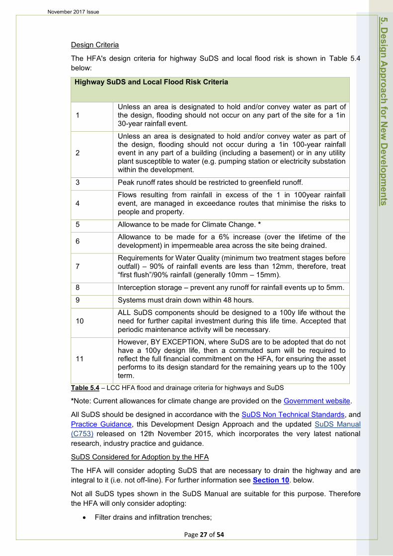
Design Criteria
The HFA's design criteria for highway SuDS and local flood risk is shown in Table 5.4 below:
Highway SuDS and Local Flood Risk Criteria
1 Unless an area is designated to hold and/or convey water as part of the design, flooding should not occur on any part of the site for a 1in 30-year rainfall event.
2
Unless an area is designated to hold and/or convey water as part of the design, flooding should not occur during a 1in 100-year rainfall event in any part of a building (including a basement) or in any utility plant susceptible to water (e.g. pumping station or electricity substation within the development.
3 Peak runoff rates should be restricted to greenfield runoff.
4 Flows resulting from rainfall in excess of the 1 in 100year rainfall event, are managed in exceedance routes that minimise the risks to people and property.
5 Allowance to be made for Climate Change. *
6 Allowance to be made for a 6% increase (over the lifetime of the development) in impermeable area across the site being drained.
7 Requirements for Water Quality (minimum two treatment stages before outfall) – 90% of rainfall events are less than 12mm, therefore, treat “first flush”/90% rainfall (generally 10mm – 15mm).
8 Interception storage – prevent any runoff for rainfall events up to 5mm.
9 Systems must drain down within 48 hours.
10 ALL SuDS components should be designed to a 100y life without the need for further capital investment during this life time. Accepted that periodic maintenance activity will be necessary.
11
However, BY EXCEPTION, where SuDS are to be adopted that do not have a 100y design life, then a commuted sum will be required to reflect the full financial commitment on the HFA, for ensuring the asset performs to its design standard for the remaining years up to the 100y term.
Table 5.4 – LCC HFA flood and drainage criteria for highways and SuDS
*Note: Current allowances for climate change are provided on the Government website.
All SuDS should be designed in accordance with the SuDS Non Technical Standards, and Practice Guidance, this Development Design Approach and the updated SuDS Manual (C753) released on 12th November 2015, which incorporates the very latest national research, industry practice and guidance.
SuDS Considered for Adoption by the HFA
The HFA will consider adopting SuDS that are necessary to drain the highway and are integral to it (i.e. not off-line). For further information see Section 10. below.
Not all SuDS types shown in the SuDS Manual are suitable for this purpose. Therefore the HFA will only consider adopting:
• Filter drains and infiltration trenches;
5. Design A
pproach for New
Developm
ents
Page 27 of 54

November 2017 Issue
• Grass filter strips; • Pervious pavements; and • Swales and surface water flow conveyance features.
Specific design requirements for each of these SuDS types are shown below. See also Appendix B of the updated SuDS Manual (C753), which includes helpful checklists for the planning and design of SuDS components.
With specific regard to the construction of SuDS and the materials used, all work should be carried out in accordance with the HFA Development Roads and Sustainable Drainage Specification and Construction.
Filter Drains & Infiltration Trenches
Photo 5.5 - SuDS Manual (C753) Chapter 16: Filter Drains
Figure 5.7 – Cross-section of typical filter drain & infiltration trench
Suitable for all road types shown in Table 5.1
Specific design requirements are provided in Table 5.5 below:
SuDS Elements Design Requirements
1. Depth of trench Between 1.0 – 2.0m & min 600mm below highway formation level
2. Width of trench Between 450 - 900mm
3. Maximum longitudinal slopes 2%
4. Minimum distance from structural foundations 5.0m
5. Minimum distance from a carriageway Situated outside the load line or 1m from the carriageway (whichever is greater)
Table 5.5 - Specific design requirements for filter drains and infiltration trenches.
5. Design A
pproach for New
Developm
ents
Page 28 of 54
November 2017 Issue
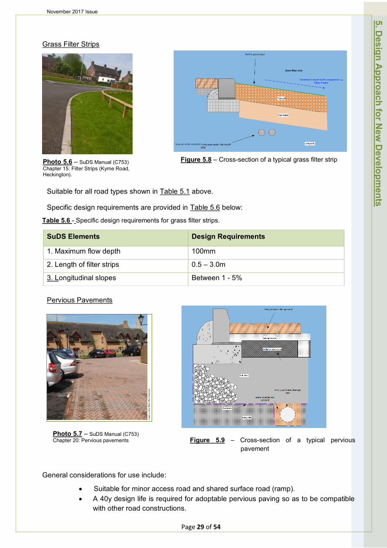
Grass Filter Strips
Photo 5.6 – SuDS Manual (C753) Chapter 15: Filter Strips (Kyme Road, Heckington).
Figure 5.8 – Cross-section of a typical grass filter strip
Suitable for all road types shown in Table 5.1 above.
Specific design requirements are provided in Table 5.6 below:
Table 5.6 - Specific design requirements for grass filter strips.
SuDS Elements Design Requirements
1. Maximum flow depth 100mm
2. Length of filter strips 0.5 – 3.0m
3. Longitudinal slopes Between 1 - 5%
Pervious Pavements
Photo 5.7 – SuDS Manual (C753) Chapter 20: Pervious pavements Figure 5.9 – Cross-section of a typical pervious
pavement
5. Design A
pproach for New
Developm
ents
General considerations for use include:
• Suitable for minor access road and shared surface road (ramp). • A 40y design life is required for adoptable pervious paving so as to be compatible
with other road constructions.
Page 29 of 54
November 2017 Issue
• Service trenches are acceptable under pervious pavements, but they should be located at dedicated crossing points and be clearly marked with a different pattern/shade/colour of blocks
Pervious pavements can be considered in SUDs design where there is suitable infiltration and the groundwater level is low enough. Specific design requirements are provided in Table 5.7 below:
SuDS Elements Design Requirements
1. Surface layer permeability >5000mm/h
2. Maximum groundwater level At least 1m below infiltration flow outlet
3. Minimum CBR value 3%
Table 5.7 - Specific design requirements for pervious pavements.
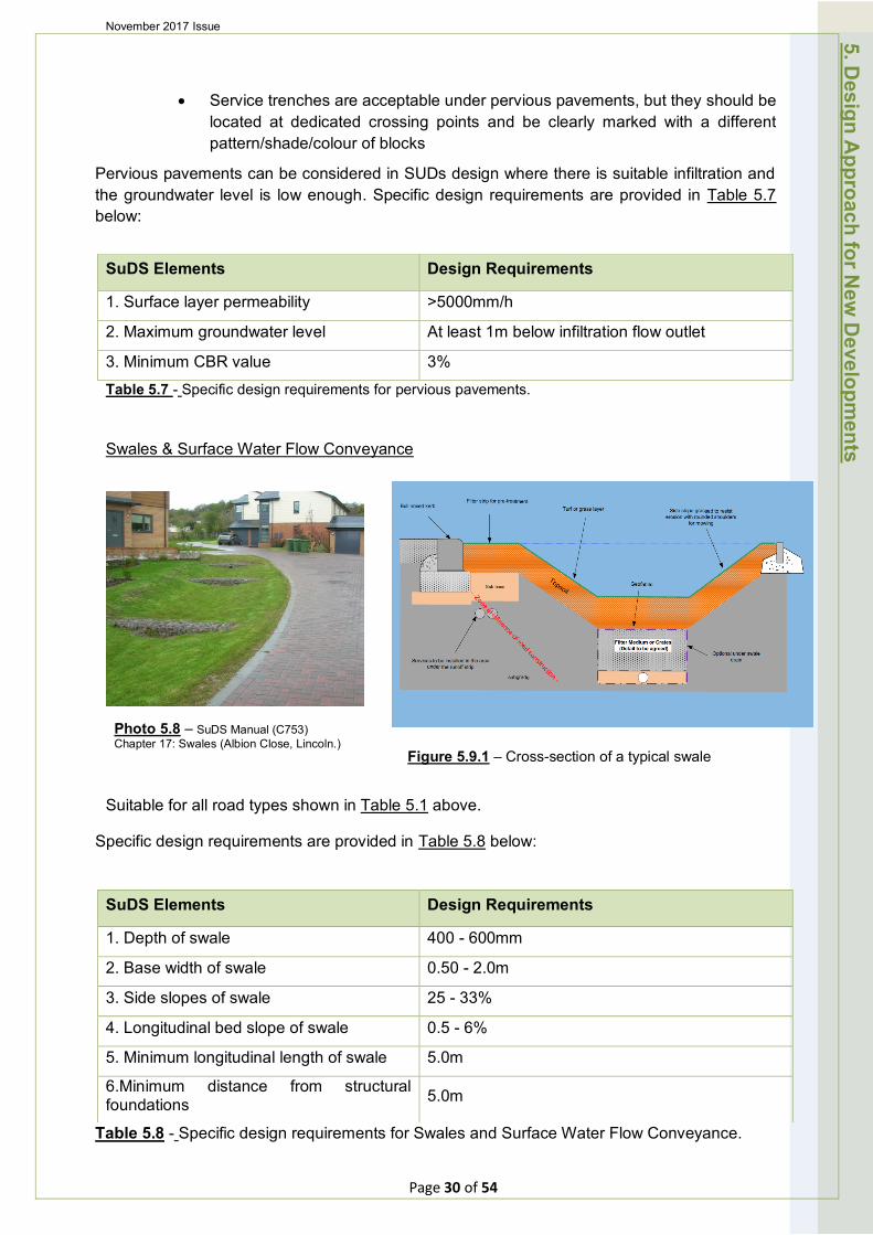
Swales & Surface Water Flow Conveyance
Photo 5.8 – SuDS Manual (C753) Chapter 17: Swales (Albion Close, Lincoln.)
Figure 5.9.1 – Cross-section of a typical swale
Suitable for all road types shown in Table 5.1 above.
Specific design requirements are provided in Table 5.8 below:
SuDS Elements Design Requirements
1. Depth of swale 400 - 600mm
2. Base width of swale 0.50 - 2.0m
3. Side slopes of swale 25 - 33%
4. Longitudinal bed slope of swale 0.5 - 6%
5. Minimum longitudinal length of swale 5.0m
6.Minimum distance from structural foundations 5.0m
5. Design A
pproach for New
Developm
ents
Table 5.8 - Specific design requirements for Swales and Surface Water Flow Conveyance.
Page 30 of 54

November 2017 Issue
5.5 Street Lighting Design
Street lighting design of the adoptable highway shall be commensurate with British Standard BS5489 -1:2013 or any subsequent superseding C.O.P. Designs are subject to approval by the HFA prior to acceptance. The HFA can provide a design service if required.
Street lights must be installed within adoptable highway and unless otherwise approved by the HFA, shall be permanently supplied by a DNO or IDNO electrical supply.
Street lighting positions shall be determined by the requirements to meet the British Standard and any impediments to illumination levels, such as planned landscape and tree design shall be eliminated or minimised at the design stage.
The street lighting design must aim to minimise electrical energy usage whilst remaining compliant. Lighting must be specified to fit in with the HFA part night policy in which lighting on developments turns off at a pre-specified time during night time hours. The HFA is to be contacted for information on timings and any proposed exceptions.
Highway adoptable footpaths remote to the carriageway on developments may be considered as being exempt from lighting if there is an alternative lit route for pedestrians.
Any lighting on remote footpaths which cannot be accessed by a vehicle must have street lighting columns which can be lowered by a one-man operation without the aid of a vehicle.
All street lighting equipment must meet the required specification of the HLLA.
Ideally street lighting columns on 30mph or less development roads shall be situated a minimum 0.8m from the carriageway edge and preferably behind a raised kerb.
On shared surface areas where a raised kerb is not available, extreme care must be taken within the design to ensure that the column is not clearly vulnerable to collision by travelling or parking vehicles.
Commuted sums may be required for a specification of street lighting equipment which exceeds the HFA requirement and would result in increased future maintenance costs.
5.6 Landscape and Tree Design
Planting should be designed by integrating it into the streetscape wherever possible. Planting, particularly of street trees can help to soften the street scene while creating visual interest, improving microclimate (reducing wind and giving shade for example) and providing valuable habitats for wildlife, which is especially important in urban areas. Planting can also be used to create buffer zones, visual barriers, or landmarks and gateway features.
Where trees are to be used in a design, careful consideration must be given to the choice of species, their location and how they are planted. Ensuring sufficient un-compacted soil is available for newly planted trees is critical to ensuring the trees establish themselves successfully, thereby minimising maintenance and replacement costs.
5. Design A
pproach for New
Developm
ents
Page 31 of 54
November 2017 Issue
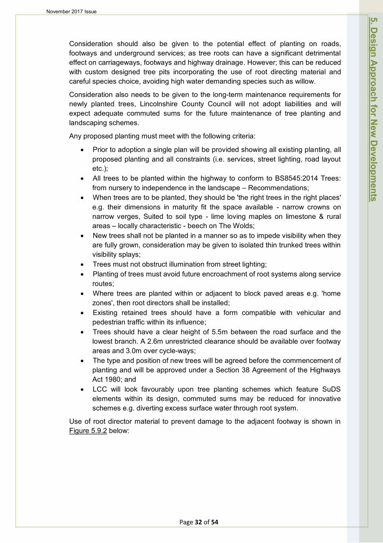
Consideration should also be given to the potential effect of planting on roads, footways and underground services; as tree roots can have a significant detrimental effect on carriageways, footways and highway drainage. However; this can be reduced with custom designed tree pits incorporating the use of root directing material and careful species choice, avoiding high water demanding species such as willow.
Consideration also needs to be given to the long-term maintenance requirements for newly planted trees, Lincolnshire County Council will not adopt liabilities and will expect adequate commuted sums for the future maintenance of tree planting and landscaping schemes.
Any proposed planting must meet with the following criteria:
• Prior to adoption a single plan will be provided showing all existing planting, all proposed planting and all constraints (i.e. services, street lighting, road layout etc.);
• All trees to be planted within the highway to conform to BS8545:2014 Trees: from nursery to independence in the landscape – Recommendations;
• When trees are to be planted, they should be 'the right trees in the right places' e.g. their dimensions in maturity fit the space available - narrow crowns on narrow verges, Suited to soil type - lime loving maples on limestone & rural areas – locally characteristic - beech on The Wolds;
• New trees shall not be planted in a manner so as to impede visibility when they are fully grown, consideration may be given to isolated thin trunked trees within visibility splays;
• Trees must not obstruct illumination from street lighting; • Planting of trees must avoid future encroachment of root systems along service
routes; • Where trees are planted within or adjacent to block paved areas e.g. 'home
zones', then root directors shall be installed; • Existing retained trees should have a form compatible with vehicular and
pedestrian traffic within its influence; • Trees should have a clear height of 5.5m between the road surface and the
lowest branch. A 2.6m unrestricted clearance should be available over footway areas and 3.0m over cycle-ways;
• The type and position of new trees will be agreed before the commencement of planting and will be approved under a Section 38 Agreement of the Highways Act 1980; and
• LCC will look favourably upon tree planting schemes which feature SuDS elements within its design, commuted sums may be reduced for innovative schemes e.g. diverting excess surface water through root system.
Use of root director material to prevent damage to the adjacent footway is shown in Figure 5.9.2 below:
5. Design A
pproach for New
Developm
ents
Page 32 of 54
November 2017 Issue
Figure 5.9.2 – Use of root director material (Courtesy of GreenBlue Urban)
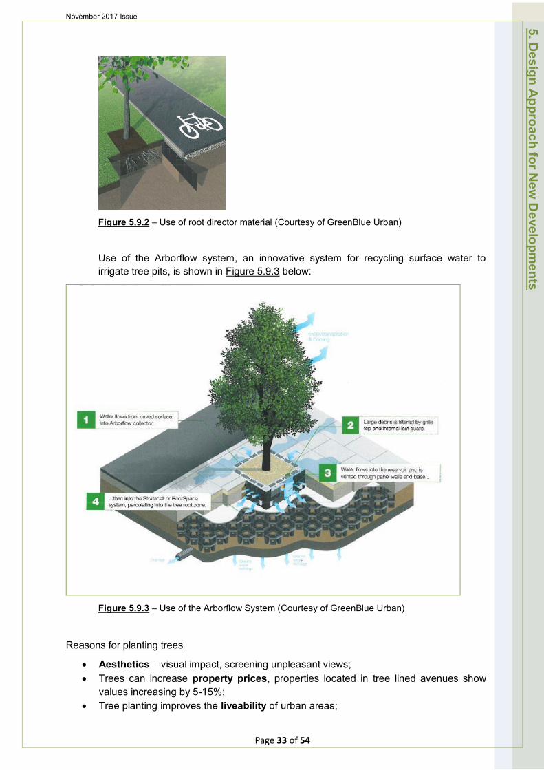
Use of the Arborflow system, an innovative system for recycling surface water to irrigate tree pits, is shown in Figure 5.9.3 below:
Figure 5.9.3 – Use of the Arborflow System (Courtesy of GreenBlue Urban)
Reasons for planting trees
• Aesthetics – visual impact, screening unpleasant views; • Trees can increase property prices, properties located in tree lined avenues show
values increasing by 5-15%; • Tree planting improves the liveability of urban areas;
5. Design A
pproach for New
Developm
ents
Page 33 of 54
November 2017 Issue
• Storm water management and buffering – the crown of a large tree is a free standing anti-flood reservoir. One hundred mature trees would capture approx. 1,137,000 litres of rainwater per year, allowing some to evaporate, drawing some through the roots system and allowing the remainder to soak into the ground;
• For every 5% of tree cover in a community, storm water run-off is reduced by 2%; • Health – Trees have a positive impact on the incidence of skin cancer, asthma,
hypertension and stress related illness by filtering out polluted air, reducing smog formation, providing shading from solar radiation and giving an attractive, calming setting for recreation;
• For every 10% increase in a cities tree canopy, Ozone is reduced by 3-7%; • Carbon reduction – trees are proven to absorb and store carbon. Planting trees is
one of the most effective means of drawing excess CO2 from the atmosphere. A mature tree can absorb 21kg of carbon per year and release enough oxygen back into the atmosphere to support 2 humans;
• Biodiversity – natural habitats for birds and other fauna; • Pollutant removal – trees will remove and store Sulphur dioxide, Nitrogen oxide,
particulate pollution, Carbon monoxide, Cadmium, Lead and Nickel; • Research has shown 60% reduction in particulates from tree lined streets; • Erosion reduction – reducing topsoil erosion through run-off and preventing harmful
chemicals reaching water courses; • Cooling effect – reducing temperatures by shading and transpiring water. This can
help to reduce air conditioning bills and therefore energy use. One mature tree can produce the same effect as 10 room sized air conditioners. This becomes an effective tool in reducing the urban heat island effect;
• Trees can save up to 10% of local energy consumption through their moderation of the local climate;
• Noise reduction; and • Wind speed reduction – buildings increase wind speeds and trees can significantly
reduce wind speed up to a distance of 10 x their height.
5. Design A
pproach for New
Developm
ents
Page 34 of 54
November 2017 Issue 6. Travel Plans
6. Travel Plans 6.1 Long term Management Strategy
A Travel Plan is a long-term management strategy for an existing or proposed development that seeks to integrate proposals for increasing sustainable travel by the future occupier(s) into the planning process; and is articulated in a document that is to be regularly reviewed by the future occupier(s) of the site. It is based on evidence in the transport assessment of the anticipated transport impacts of the proposal and involves the development of agreed and specific outcomes; linked to an appropriate package of measures aimed at encouraging sustainable travel.
The NPPF "Sustainable Transport – 2012" reinforces the importance of travel plans in the planning context. Paragraph 36 sets out that all developments which generate significant amounts of movement should be required to provide a Travel Plan. It should be considered in parallel to development proposals and readily integrated into the design and occupation of the new site. It should also support Transport Assessments (TAs) in taking forward the identified mitigation measures which relate to on-going occupation and operation of the development.
The 4th Lincolnshire Local Transport Plan 2013/2014-2022/23 and the Draft Central Lincolnshire Local Plan 2011/2013 also focus on the importance and requirements of travel planning.
Lincolnshire County Council's Guidance Notes for the preparation and implementation of Development Travel Plans explains in detail the various travel plans and the process and provides guidance to writing a plan along with a toolkit of measures that developers can consider.
6.2 Links for Reference
National Policy Planning Framework:
http://planningguidance.communities.gov.uk/blog/guidance/travel-plans-transport-assessments-and-statements-in-decision-taking/travel-plans/
LCC Guidance:
http://www.lincolnshire.gov.uk/transport-and-roads/strategy-policy-and-licences/control-of-new-development-affecting-the-highway/preparing-development-proposals/preparing-travel-plans/88371.article
Other Guidance:
"Making residential travel plans work: good practice guidelines for new developments – September 2005" is another useful document providing further information: http://travl.org/downloads/Publications/Useful%20Documents/Making%20Residential%20 Travel%20Plans%20Work.pdf
7. Parking Provision 7.1 General
Careful consideration should be given to parking provision when planning a development. When designing streets that are to be attractive, safe and friendly, parking will normally have a strong degree of success. An over provision can result in poor design, wasted
Page 35 of 54
November 2017 Issue
space and an apparent encouragement to use cars in preference to walking, cycling, and public transport. While the implications of having too little provision can have serious effects on highway safety as a result of on street parking.
Whilst sustainable modes of travel should be promoted, it should also be recognised that the offering of good bus services and cycle routes does not necessarily mean that car ownership levels will be reduced. It is not unusual that those that choose to travel sustainably for a large proportion of their journeys, will also own motor vehicles, for which parking provision should be provided.
Most car owners like to be able to see their vehicles and to know that they are securely parked. Rear parking courts are often under-utilised when provided in areas without on-street controls to maximise their use, and often lead to serious on-street problems.
7.2 Issues Caused by Inadequate Parking Provision
Pavement parking:
• Obstruction of driveways and accesses; • Hindered access to service and emergency vehicles; • Damage to soft landscaping and footways; • Cluttered, unsightly streets; and • Neighbour disputes.
Otherwise well-designed neighbourhoods are often compromised in terms of their appearance and enjoyment by ill-considered approaches to the provision of parking for residents, and their visitors.
Parking spaces within streets and accessed directly from them minimise the amount of land given over to accesses and manoeuvring areas. If cleverly positioned they can help to restrain speeds, as well as reducing the likelihood of indiscriminate and obstructive parking.
When creating shared space streets on-street parking can be formal or informal. Squares and other spaces are particularly good for parking in the wider context of the sense of place, particularly when accompanied by strong landscaping to ensure that it does not dominate the street scene. Visitor parking should also be considered.
7.3 Garages
Garages should only be considered as parking provision when they are of a size that will accommodate general storage (such as lawn mowers, hedge trimmers, ladders etc.) and have garage doors that are wide enough to accommodate the modern car.
The length of any driveway fronting a domestic garage should be 6 metres, where an up and over type garage door is provided. If a vertically open door (roller type) is to be provided. The length of the driveway may be reduced to 5 metres.
7.4 Service Vehicles and Essential Operational Parking
The servicing requirements of a proposal will vary considerably depending upon the type and size of development. Applicants will be required to demonstrate that any development proposals include adequate provision on site to allow for loading, unloading and turning of service vehicles without endangering road safety.
7.5 Cycle Parking
7. Parking Provision
Page 36 of 54
November 2017 Issue
The provision of convenient secure parking and related facilities are fundamental to attracting modal shift to cycling, particularly from single occupancy motorised journeys made over shorter distances on a regular basis. At large development sites, the exact number of cycle parking spaces will depend on the individual characteristics of the site and its surrounding area. Cycle theft is a major deterrent to potential cyclists, suitable cycle parking should therefore be provided for both employees and visitors/customers. In general cycle parking should be:
• In a secure, easily accessible position regularly overlooked by staff or passers-by;
• Adjacent to the entrance, particularly for visitors; • Well signed and lit; • Ideally under cover; and • Positioned so as not to present a hazard to pedestrians, particularly those with
impaired vision.
At larger sites, additional needs of employees who cycle should be provided through the provision of facilities such as lockers, changing and shower facilities as part of an overall Travel Plan.
Type of stand
Cycle parking for public use will generally be of the ‘Sheffield Stand’ type, which allow cycles to be easily supported and the frame and wheels to be locked.
Photo 7.1 – Typical cycle parking stands
Number of stands required:
TYPE OF DEVELOPMENT
Food Retail 1 stand per 250 m2 ground floor area (gfa).
Non - Food Retail 1 stand per 500 m2 gfa.
Offices 1 stand per 200 m2 gfa.
General Industry 1 stand per 200 m2 gfa.
Warehousing 1 stand per 1000 m2 gfa.
Cinema/ Theatres/ Conference Facilities/Other Places of Assembly with Fixed Seating
1 stand per 20 seats.
Schools, Sixth Forms and Colleges 1 stand for every 10 pupils
1 stand for every 10 staff Table 7.1 – Number of cycle stands for different types of development
7.6 Provision for Motorised Two-Wheeler Parking
Parking for powered two wheels should be provided at 1 space per 20 parking spaces. Secure anchor points to which the machines may be locked should be provided.
In general, parking for Powered two wheelers should be:
• Flat, level and firm to prevent stands sinking into the ground;
Page 37 of 54
7. Parking Provision

November 2017 Issue
• In a secure position regularly overlooked by staff or passers-by; • As near to the entrance as the site layout permits; • Well signed and lit; • Ideally under cover, but if this is not possible, clear of trees; • Positioned as to not present a hazard to pedestrians, particularly those with
impaired vision; and • Designed to ensure that they are not used by cars or other vehicles.
In addition, at larger sites, additional needs of employees who used powered two wheelers should be provided, such as lockers and changing facilities.
7.7 Disability Parking
Under the Disability Discrimination Act 2005, it is the responsibility of site occupiers to ensure that adequate provision is made for the needs of people with disabilities. The number of spaces required for people with disabilities varies between use classes and the standard has been based on the DfTs Traffic Advisory Leaflet 5/95: ‘Parking for Disabled People’.
The recommended proportions of spaces for Blue Badge holders are:
• For car parks associated with existing employment premises: 2% of the total car park capacity, with a minimum of one space;
• Spaces for disabled employees must be additional to those recommended above; reservations could be ensured, for example, by marking a space with a registration number;
• For car parks associated with new employment premises: 5% of the total parking capacity should be designated (to include both employees and visitors); and
• For car parks associated with shopping areas, leisure or recreational facilities, and places open to the general public: A minimum of one space for each employee who is a disabled motorist, plus 6% of the total capacity for visiting disabled motorists.
The numbers of designated spaces may need to be greater at hotels and sports stadia that specialize in accommodating groups of disabled people.
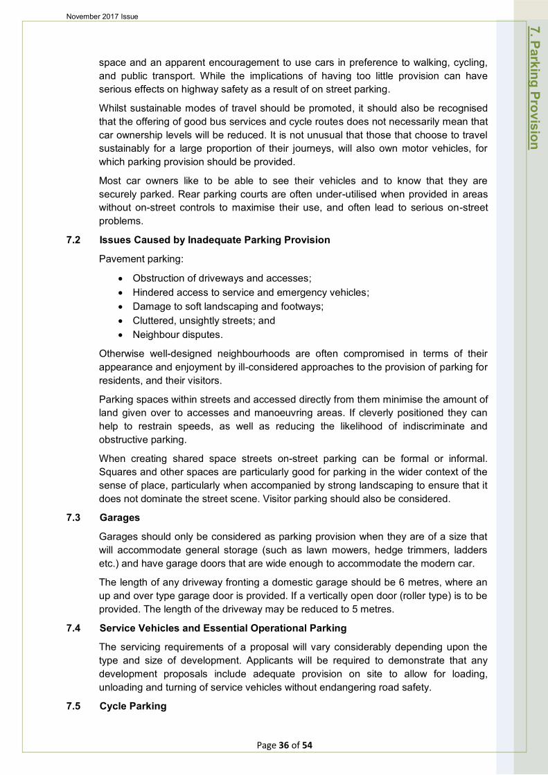
Car parking spaces for people with disabilities should be located as close as possible to the main entrance (or to an alternative fully accessible entrance if the main entrance does not meet these requirements). Appropriate dropped kerbing should be provided. Adequate space should be provided to enable wheelchair users to easily gain access to and from their cars. Typical layouts are shown in Figure 7.1 below.
Parking for Disability Scooters
All normal parking restrictions should be observed. Vehicles should not be left unattended if they cause an obstruction to other pedestrians – especially those in wheelchairs.
7.8 Layout of Parking Spaces
7. Parking Provision
Page 38 of 54
November 2017 Issue
A standard parking space should be 2.5 x 5 metres and typical parking layouts are detailed below:
Figure 7.1 – Typical parking layout for the disabled.
2500 2500 2500
2500
5000
Figure 7.2 – Typical two-way flow parking layout
7. Parking Provision
Page 39 of 54
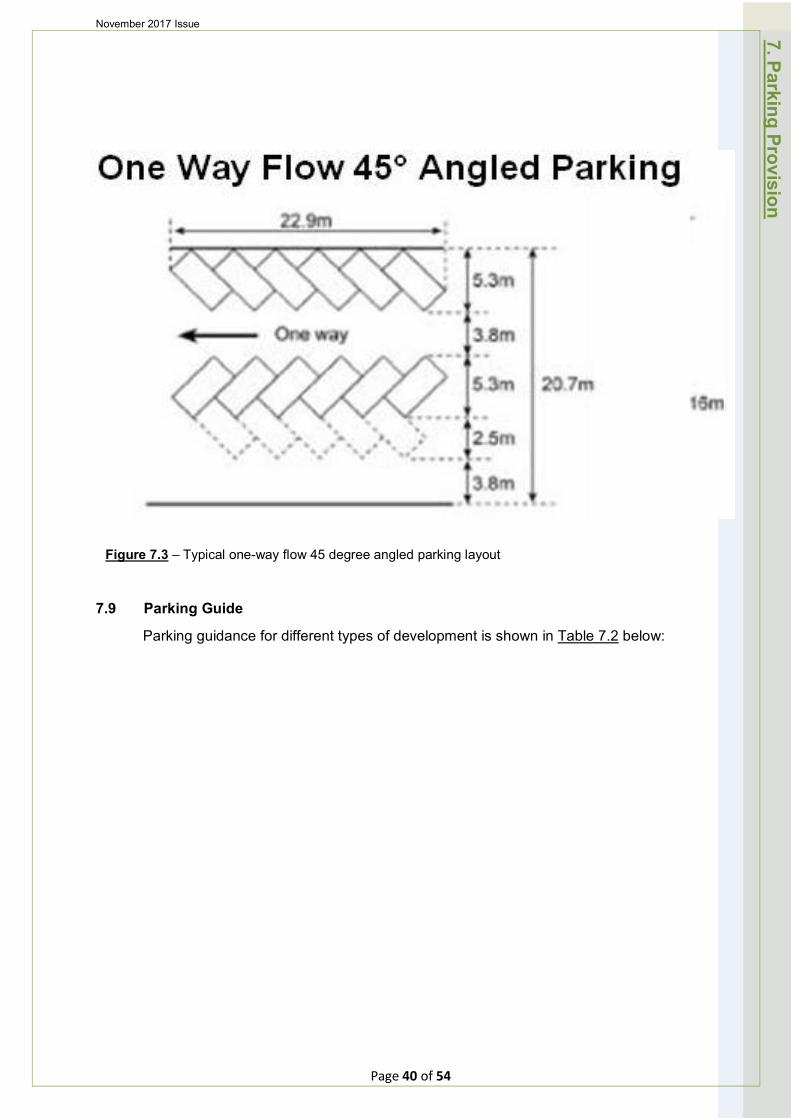
November 2017 Issue 7. Parking Provision
Figure 7.3 – Typical one-way flow 45 degree angled parking layout
7.9 Parking Guide
Parking guidance for different types of development is shown in Table 7.2 below:
Page 40 of 54
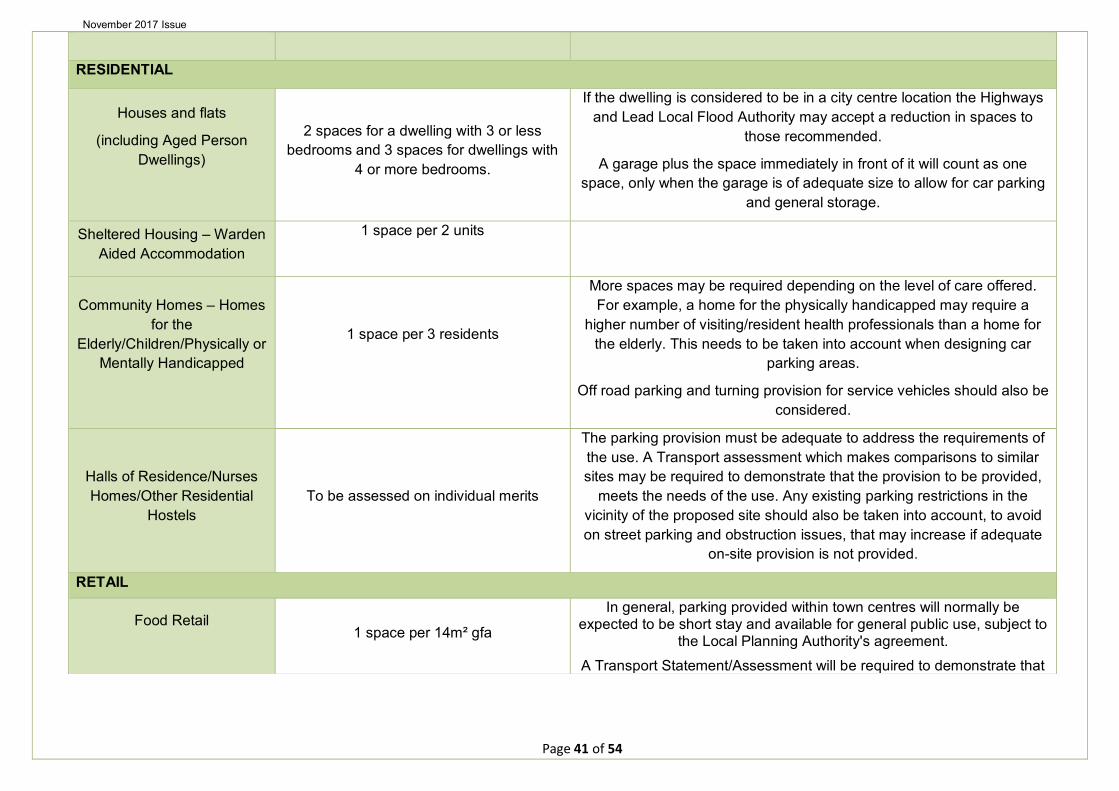
November 2017 Issue
TYPE OF DEVELOPMENT RECOMMENDED NOTES
RESIDENTIAL
Houses and flats
(including Aged Person Dwellings)
2 spaces for a dwelling with 3 or less bedrooms and 3 spaces for dwellings with
4 or more bedrooms.
If the dwelling is considered to be in a city centre location the Highways and Lead Local Flood Authority may accept a reduction in spaces to
those recommended.
A garage plus the space immediately in front of it will count as one space, only when the garage is of adequate size to allow for car parking
and general storage.
Sheltered Housing – Warden Aided Accommodation
1 space per 2 units
Community Homes – Homes for the
Elderly/Children/Physically or Mentally Handicapped
1 space per 3 residents
More spaces may be required depending on the level of care offered. For example, a home for the physically handicapped may require a
higher number of visiting/resident health professionals than a home for the elderly. This needs to be taken into account when designing car
parking areas.
Off road parking and turning provision for service vehicles should also be considered.
Halls of Residence/Nurses Homes/Other Residential
Hostels To be assessed on individual merits
The parking provision must be adequate to address the requirements of the use. A Transport assessment which makes comparisons to similar sites may be required to demonstrate that the provision to be provided,
meets the needs of the use. Any existing parking restrictions in the vicinity of the proposed site should also be taken into account, to avoid on street parking and obstruction issues, that may increase if adequate
on-site provision is not provided.
RETAIL
Food Retail 1 space per 14m² gfa
In general, parking provided within town centres will normally be expected to be short stay and available for general public use, subject to
the Local Planning Authority's agreement.
A Transport Statement/Assessment will be required to demonstrate that
Page 41 of 54

November 2017 Issue
the proposed parking provision is adequate.
Off road parking and turning provision for service vehicles should also be considered and provided where necessary.
Non – Food Retail 1 space per 20m² gfa
(including any external display area) Ditto.
EMPLOYMENT
Offices 1 space per 30m² gfa
A Transport Statement/Assessment will be required to demonstrate that the proposed parking provision is adequate for the use.
Off road parking and turning provision for service vehicles should also be considered and provided where necessary.
General Industry 1 space per 65m² gfa Ditto.
Warehousing 1 space per 150m² gfa Ditto.
EDUCATION
Nursery Schools/Primary Schools/Secondary Schools
To be assessed on individual merits, but typically 1 space per 2 staff plus an
allowance for visitors.
A School Travel Plan is likely to be required in support of any proposal.
Off road parking and turning provision for service vehicles should also be considered and provided where necessary.
Higher and Further Education
To be assessed on individual merits, but typically 1 space per 2 staff plus 1 space
per 15 students
A Transport Assessment and/or Travel Plan are likely to be required in support of any proposal.
Off road parking and turning provision for service vehicles should also be considered and provided where necessary.
OTHER DEVELOPMENT TYPES
Cinema/Theatres/Conference Facilities/Bingo Halls/Other
Places of Assembly with fixed seating
1 space per 5 seats Off road parking and turning provision for service vehicles should also be considered and provided where necessary.
Sports Facilities (e.g. Leisure Centre/Swimming
Pools/Squash Clubs) To be assessed on individual merits
A Transport Assessment and/or Travel Plan is likely to be required in support of any proposal. This will need to include provision of coach
parking at larger sites.
Off road parking and turning provision for service vehicles should also be
Page 42 of 54
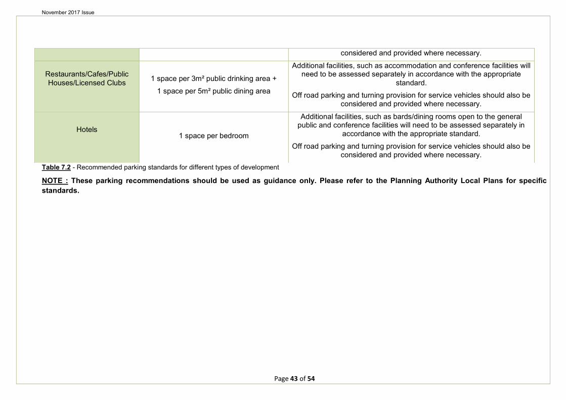
November 2017 Issue
considered and provided where necessary.
Restaurants/Cafes/Public Houses/Licensed Clubs 1 space per 3m² public drinking area +
1 space per 5m² public dining area
Additional facilities, such as accommodation and conference facilities will need to be assessed separately in accordance with the appropriate
standard.
Off road parking and turning provision for service vehicles should also be considered and provided where necessary.
Hotels 1 space per bedroom
Additional facilities, such as bards/dining rooms open to the general public and conference facilities will need to be assessed separately in
accordance with the appropriate standard.
Off road parking and turning provision for service vehicles should also be considered and provided where necessary.
Table 7.2 - Recommended parking standards for different types of development
NOTE : These parking recommendations should be used as guidance only. Please refer to the Planning Authority Local Plans for specific standards.
Page 43 of 54
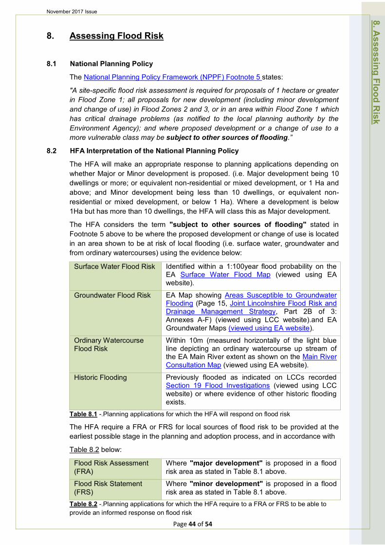
November 2017 Issue
8. Assessing Flood Risk
8.1 National Planning Policy
The National Planning Policy Framework (NPPF) Footnote 5 states:
"A site-specific flood risk assessment is required for proposals of 1 hectare or greater in Flood Zone 1; all proposals for new development (including minor development and change of use) in Flood Zones 2 and 3, or in an area within Flood Zone 1 which has critical drainage problems (as notified to the local planning authority by the Environment Agency); and where proposed development or a change of use to a more vulnerable class may be subject to other sources of flooding.”
8.2 HFA Interpretation of the National Planning Policy
The HFA will make an appropriate response to planning applications depending on whether Major or Minor development is proposed. (i.e. Major development being 10 dwellings or more; or equivalent non-residential or mixed development, or 1 Ha and above; and Minor development being less than 10 dwellings, or equivalent non-residential or mixed development, or below 1 Ha). Where a development is below 1Ha but has more than 10 dwellings, the HFA will class this as Major development.
The HFA considers the term "subject to other sources of flooding" stated in Footnote 5 above to be where the proposed development or change of use is located in an area shown to be at risk of local flooding (i.e. surface water, groundwater and from ordinary watercourses) using the evidence below:
Surface Water Flood Risk Identified within a 1:100year flood probability on the EA Surface Water Flood Map (viewed using EA website).
Groundwater Flood Risk EA Map showing Areas Susceptible to Groundwater Flooding (Page 15, Joint Lincolnshire Flood Risk and Drainage Management Strategy, Part 2B of 3: Annexes A-F) (viewed using LCC website).and EA Groundwater Maps (viewed using EA website).
Ordinary Watercourse Flood Risk
Within 10m (measured horizontally of the light blue line depicting an ordinary watercourse up stream of the EA Main River extent as shown on the Main River Consultation Map (viewed using EA website).
Historic Flooding Previously flooded as indicated on LCCs recorded Section 19 Flood Investigations (viewed using LCC website) or where evidence of other historic flooding exists.
Table 8.1 -.Planning applications for which the HFA will respond on flood risk
The HFA require a FRA or FRS for local sources of flood risk to be provided at the earliest possible stage in the planning and adoption process, and in accordance with
Table 8.2 below:
Flood Risk Assessment (FRA)
Where "major development" is proposed in a flood risk area as stated in Table 8.1 above.
Flood Risk Statement (FRS)
Where "minor development" is proposed in a flood risk area as stated in Table 8.1 above.
8. Assessing Flood R
isk
Table 8.2 -.Planning applications for which the HFA require to a FRA or FRS to be able to provide an informed response on flood risk
Page 44 of 54
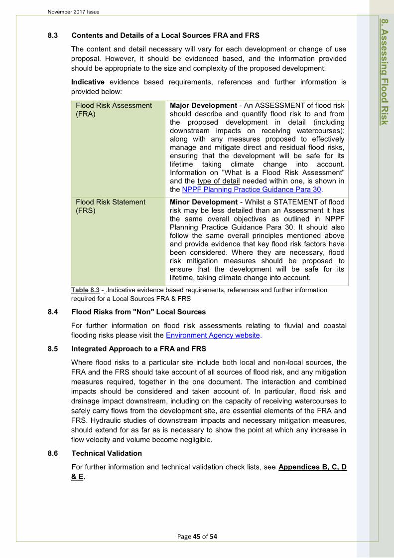
November 2017 Issue
8.3 Contents and Details of a Local Sources FRA and FRS
The content and detail necessary will vary for each development or change of use proposal. However, it should be evidenced based, and the information provided should be appropriate to the size and complexity of the proposed development.
Indicative evidence based requirements, references and further information is provided below:
Flood Risk Assessment (FRA)
Major Development - An ASSESSMENT of flood risk should describe and quantify flood risk to and from the proposed development in detail (including downstream impacts on receiving watercourses); along with any measures proposed to effectively manage and mitigate direct and residual flood risks, ensuring that the development will be safe for its lifetime taking climate change into account. Information on "What is a Flood Risk Assessment" and the type of detail needed within one, is shown in the NPPF Planning Practice Guidance Para 30.
Flood Risk Statement (FRS)
Minor Development - Whilst a STATEMENT of flood risk may be less detailed than an Assessment it has the same overall objectives as outlined in NPPF Planning Practice Guidance Para 30. It should also follow the same overall principles mentioned above and provide evidence that key flood risk factors have been considered. Where they are necessary, flood risk mitigation measures should be proposed to ensure that the development will be safe for its lifetime, taking climate change into account.
Table 8.3 - .Indicative evidence based requirements, references and further information required for a Local Sources FRA & FRS
8.4 Flood Risks from "Non" Local Sources
For further information on flood risk assessments relating to fluvial and coastal flooding risks please visit the Environment Agency website.
8.5 Integrated Approach to a FRA and FRS
Where flood risks to a particular site include both local and non-local sources, the FRA and the FRS should take account of all sources of flood risk, and any mitigation measures required, together in the one document. The interaction and combined impacts should be considered and taken account of. In particular, flood risk and drainage impact downstream, including on the capacity of receiving watercourses to safely carry flows from the development site, are essential elements of the FRA and FRS. Hydraulic studies of downstream impacts and necessary mitigation measures, should extend for as far as is necessary to show the point at which any increase in flow velocity and volume become negligible.
8.6 Technical Validation
For further information and technical validation check lists, see Appendices B, C, D & E.
8. Assessing Flood R
isk
Page 45 of 54
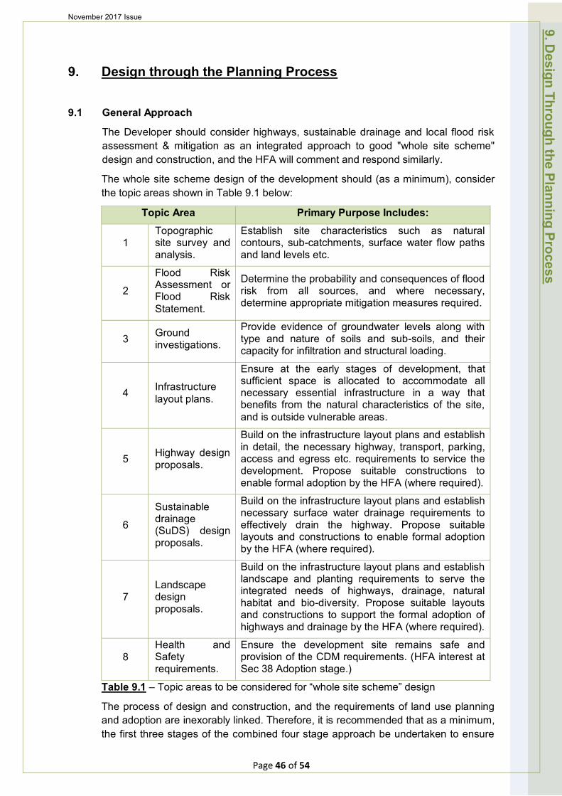
November 2017 Issue
9. Design through the Planning Process
9.1 General Approach
The Developer should consider highways, sustainable drainage and local flood risk assessment & mitigation as an integrated approach to good "whole site scheme" design and construction, and the HFA will comment and respond similarly.
The whole site scheme design of the development should (as a minimum), consider the topic areas shown in Table 9.1 below:
Topic Area Primary Purpose Includes:
1 Topographic site survey and analysis.
Establish site characteristics such as natural contours, sub-catchments, surface water flow paths and land levels etc.
2
Flood Risk Assessment or Flood Risk Statement.
Determine the probability and consequences of flood risk from all sources, and where necessary, determine appropriate mitigation measures required.
3 Ground investigations.
Provide evidence of groundwater levels along with type and nature of soils and sub-soils, and their capacity for infiltration and structural loading.
4 Infrastructure layout plans.
Ensure at the early stages of development, that sufficient space is allocated to accommodate all necessary essential infrastructure in a way that benefits from the natural characteristics of the site, and is outside vulnerable areas.
5 Highway design proposals.
Build on the infrastructure layout plans and establish in detail, the necessary highway, transport, parking, access and egress etc. requirements to service the development. Propose suitable constructions to enable formal adoption by the HFA (where required).
6
Sustainable drainage (SuDS) design proposals.
Build on the infrastructure layout plans and establish necessary surface water drainage requirements to effectively drain the highway. Propose suitable layouts and constructions to enable formal adoption by the HFA (where required).
7 Landscape design proposals.
Build on the infrastructure layout plans and establish landscape and planting requirements to serve the integrated needs of highways, drainage, natural habitat and bio-diversity. Propose suitable layouts and constructions to support the formal adoption of highways and drainage by the HFA (where required).
8 Health and Safety requirements.
Ensure the development site remains safe and provision of the CDM requirements. (HFA interest at Sec 38 Adoption stage.)
9. Design Through the Planning Process
Table 9.1 – Topic areas to be considered for “whole site scheme” design
The process of design and construction, and the requirements of land use planning and adoption are inexorably linked. Therefore, it is recommended that as a minimum, the first three stages of the combined four stage approach be undertaken to ensure
Page 46 of 54
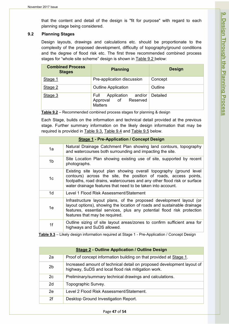
November 2017 Issue
that the content and detail of the design is "fit for purpose" with regard to each planning stage being considered.
9.2 Planning Stages
Design layouts, drawings and calculations etc. should be proportionate to the complexity of the proposed development, difficulty of topography/ground conditions and the degree of flood risk etc. The first three recommended combined process stages for “whole site scheme” design is shown in Table 9.2 below:
Combined Process Stages Planning Design
Stage 1 Pre-application discussion Concept
Stage 2 Outline Application Outline
Stage 3 Full Application and/or Approval of Reserved Matters
Detailed
Table 9.2 – Recommended combined process stages for planning & design
Each Stage, builds on the information and technical detail provided at the previous stage. Further summary information on the likely design information that may be required is provided in Table 9.3, Table 9.4 and Table 9.5 below.
Stage 1 - Pre-Application / Concept Design
1a Natural Drainage Catchment Plan showing land contours, topography and watercourses both surrounding and impacting the site.
1b Site Location Plan showing existing use of site, supported by recent photographs.
1c
Existing site layout plan showing overall topography (ground level contours) across the site, the position of roads, access points, footpaths, road drains, watercourses and any other flood risk or surface water drainage features that need to be taken into account.
1d Level 1 Flood Risk Assessment/Statement
1e
Infrastructure layout plans, of the proposed development layout (or layout options), showing the location of roads and sustainable drainage features, essential services, plus any potential flood risk protection features that may be required.
1f Outline sizing of site layout areas/zones to confirm sufficient area for highways and SuDS allowed.
Table 9.3 – Likely design information required at Stage 1 - Pre-Application / Concept Design
Stage 2 - Outline Application / Outline Design
2a Proof of concept information building on that provided at Stage 1.
2b Increased amount of technical detail on proposed development layout of highway, SuDS and local flood risk mitigation work.
2c Preliminary/summary technical drawings and calculations.
2d Topographic Survey.
2e Level 2 Flood Risk Assessment/Statement.
2f Desktop Ground Investigation Report.
9. Design Through the Planning Process
Page 47 of 54
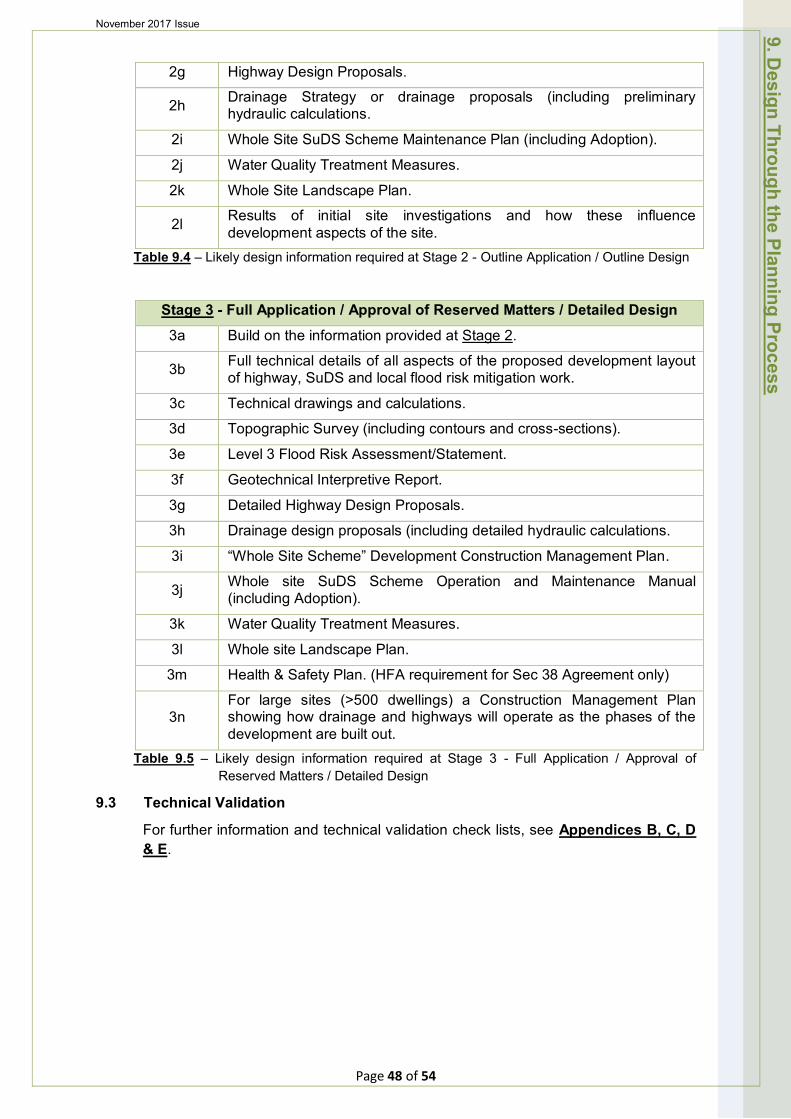
November 2017 Issue
2g Highway Design Proposals.
2h Drainage Strategy or drainage proposals hydraulic calculations.
(including preliminary
2i Whole Site SuDS Scheme Maintenance Plan (including Adoption).
2j Water Quality Treatment Measures.
2k Whole Site Landscape Plan.
2l Results of initial site investigations and development aspects of the site.
how these influence
Table 9.4 – Likely design information required at Stage 2 - Outline Application / Outline Design
Stage 3 - Full Application / Approval of Reserved Matters / Detailed Design
3a Build on the information provided at Stage 2.
3b Full technical details of all aspects of the proposed development layout of highway, SuDS and local flood risk mitigation work.
3c Technical drawings and calculations.
3d Topographic Survey (including contours and cross-sections).
3e Level 3 Flood Risk Assessment/Statement.
3f Geotechnical Interpretive Report.
3g Detailed Highway Design Proposals.
3h Drainage design proposals (including detailed hydraulic calculations.
3i “Whole Site Scheme” Development Construction Management Plan.
3j Whole site SuDS Scheme Operation and Maintenance Manual (including Adoption).
3k Water Quality Treatment Measures.
3l Whole site Landscape Plan.
3m Health & Safety Plan. (HFA requirement for Sec 38 Agreement only)
3n For large sites (>500 dwellings) a Construction Management Plan showing how drainage and highways will operate as the phases of the development are built out.
Table 9.5 – Likely design information required at Stage 3 - Full Application / Approval of Reserved Matters / Detailed Design
9.3 Technical Validation
For further information and technical validation check lists, see Appendices B, C, D & E.
9. Design Through the Planning Process
Page 48 of 54

'
November 2017 Issue
10. Highway & SuDS Agreements & Adoption
10.1 Adoption of Highways, SuDS, Public Open Spaces and Parking Areas
Adoption is the Final Stage (Stage 4), of the combined four stage approach for the design and construction of highways, SuDS and local flood risk mitigation measures. The Developer should consult the most appropriate SuDS adopting authority i.e. HFA, Water and Sewerage Company, Internal Drainage Board or Local District Council at the earliest stage in the planning and design process. Agreement in principle to adopt various roads, services (including sustainable drainage facilities) and any flood risk mitigation measures should be obtained. Failure to do so could result in additional costs to the Developer. In general, the following approach to adoption of assets will apply as shown in Table 10.1 below:
FEATURES ADOPTING AUTHORITY / ENTITY
Roads (including gullies and connections), footways, cycleways and areas within visibility splays.
HFA under the Highways Act 1980.
Street lighting on adoptable roads. HFA under the Highways Act 1980.
*Sustainable surface water drainage systems for the primary purpose of draining the highway only and serving 5 or more properties (may be acceptable to drain surface water from domestic property).
Water and Sewerage Company under Section 104 Water Industry Act 1991 (and recover costs via water rates) or HFA.
*Sustainable surface water drainage systems for the primary purpose of draining the highway only and serving less than 5 properties.
Management Company or Residents.
*Sustainable surface water drainage systems for the primary purpose of draining property (may be acceptable to drain surface water from the highway).
Water and Sewerage Company under Section 104 Water Industry Act 1991 (and recover costs via water rates).
*Sustainable surface water drainage features in public open spaces, comprising large earth channels, basins and ponds.
Local District Council, Internal Drainage Board or Management Company.
Foul Water Sewers. Water and Sewerage Company under Section 104 Water Industry Act 1991 (and recover costs via water rates).
Public open spaces, amenity areas and play areas. Local District Council.
Parking Areas. Management Company or Residents.
Local flood risk mitigation features. Local District Council, Management Company or Residents.
10. Highw
ay & SuD
S A
doption and Agreem
ents
Table 10.1 – Scheme assets & relevant adopting authority
*Further information on SuDS components and indicative SuDS adopting authorities Page 49 of 54
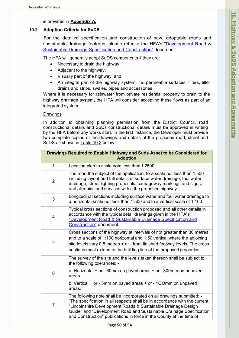
November 2017 Issue
is provided in Appendix A.
10.2 Adoption Criteria for SuDS
For the detailed specification and construction of new, adoptable roads and sustainable drainage features, please refer to the HFA's "Development Road & Sustainable Drainage Specification and Construction" document.
The HFA will generally adopt SuDS components if they are: • Necessary to drain the highway; • Adjacent to the highway; • Visually part of the highway; and • An integral part of the highway system. i.e. permeable surfaces, filters, filter
drains and strips, swales, pipes and accessories. Where it is necessary for rainwater from private residential property to drain to the highway drainage system, the HFA will consider accepting these flows as part of an integrated system.
Drawings
In addition to obtaining planning permission from the District Council, road constructional details and SuDs constructional details must be approved in writing by the HFA before any works start. In the first instance, the Developer must provide two complete copies of the drawings and details of the proposed road, street and SuDS as shown in Table 10.2 below:
Drawings Required to Enable Highway and Suds Asset to be Considered for Adoption
1 Location plan to scale note less than 1:2500.
2
The road the subject of the application, to a scale not less than 1:500 including layout and full details of surface water drainage, foul water drainage, street lighting proposals, carriageway markings and signs, and all mains and services within the proposed highway.
3 Longitudinal sections including surface water and foul water drainage to a horizontal scale not less than 1:500 and to a vertical scale of 1:100.
4
Typical cross sections of construction proposed and all other details in accordance with the typical detail drawings given in the HFA's "Development Road & Sustainable Drainage Specification and Construction" document.
5
Cross sections of the highway at intervals of not greater than 30 metres and to a scale of 1:100 horizontal and 1:50 vertical where the adjoining site levels vary 0.5 metres + or - from finished footway levels. The cross sections must extend to the building line of the proposed properties;
6
The survey of the site and the levels taken thereon shall be subject to the following tolerances: -
a. Horizontal + or - 60mm on paved areas + or - 300mm on unpaved areas
b. Vertical + or - 5mm on paved areas + or - 1OOmm on unpaved areas.
7
The following note shall be incorporated on all drawings submitted: -“The specification in all respects shall be in accordance with the current "Lincolnshire Development Roads & Sustainable Drainage Design Guide" and “Development Road and Sustainable Drainage Specification and Construction” publications in force in the County at the time of
10. Highw
ay & SuD
S A
doption and Agreem
ents
Page 50 of 54

November 2017 Issue
construction. Table 10.2 - Drawings required to enable highway and SuDS assets to be considered for
adoption
Upon completion and before the development is entered into the maintenance period, the developer shall carry out an as built drainage and carriageway level survey and provide the HFA with as built drawings showing the as built levels plotted against the design sections to demonstrate compatibility with the design and to ensure that minimum falls are achieved.
Sustainable Drainage System Service Fee
When adopting SuDS components, in addition to existing highway related bonds, fees and charges, and where private water is allowed to drain to the highway drainage system; a "one off" service payment will be required by the HFA from the Developer. Payment is required prior to commencement of SuDS construction and is related to the current Water and Sewerage Company surface water charge levied on property already connected to surface water sewerage infrastructure. Calculation details of this service payment will be provided by the HFA at pre-planning application consultation stage.
The HFA will not adopt SuDS components that are "off line" or remote from the highway. Also, the HFA will only consider adoption of the highway and relevant SuDS as an integrated process and not as separate entities.
10.3 SuDS Scheme Operation and Maintenance Manual
The HFA require a SuDS Scheme Operation and Maintenance Manual to be provided for submission at the Full Planning and Approval of Reserved Matters planning stages, as well as for the Draft Section 38 Highway and SuDS Adoption Agreement.
The manual should cover regular, occasional and remedial maintenance, and provide the HFA with details of all operations and routine maintenance activities necessary throughout the full design life of all SuDS assets involved. The content should be simple and straight forward, and include operation and maintenance checklists and schedules etc. for HFA officers to use. The manual will be part of the documentation required under CDM (i.e. part of the health and safety file).
Guidance on the contents of the manual is provided in Table 10.3 below and more detailed guidance is provided in Chapter 32 and Appendix B, SuDS Manual (C753)
SuDS Scheme Operation and Maintenance Manual
1 Location of all SuDS components on the site.
2 Brief summary of design intent, how the SuDS components work, their purpose and potential performance risks.
3 Depth of silt that will trigger requirement for removal.
4 Visual indicators that will trigger maintenance.
5 Depth of oil in separators etc. that will trigger removal.
6 Maintenance requirements (i.e. the Maintenance Plan see Chapter 32.10 and Appendix B, SuDS Manual (C753)) and a maintenance record pro-forma.
7 Explanation of the objectives of the maintenance proposed and potential implications of not meeting those objectives split into planted and hard
10. Highw
ay & SuD
S A
doption and Agreem
ents
Page 51 of 54
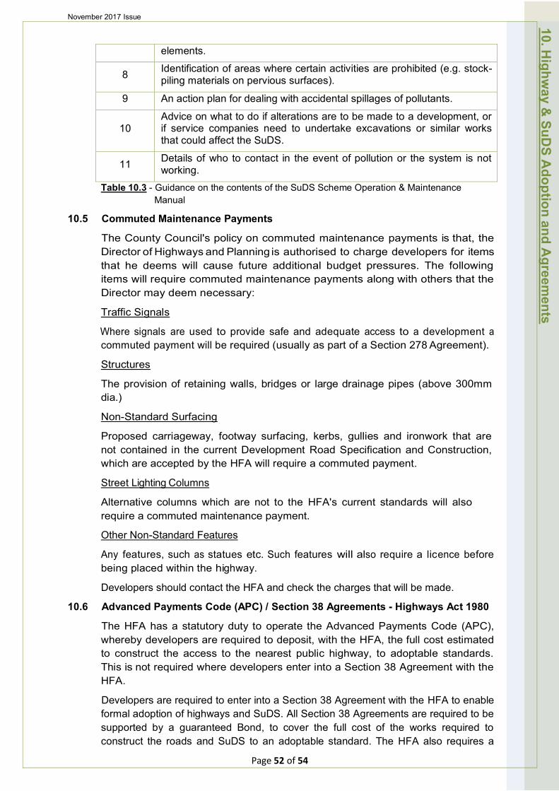
November 2017 Issue
elements.
8 Identification of areas where certain activities are prohibited (e.g. stock-piling materials on pervious surfaces).
9 An action plan for dealing with accidental spillages of pollutants.
10 Advice on what to do if alterations are to be made to a development, or if service companies need to undertake excavations or similar works that could affect the SuDS.
11 Details of who to contact in the event of pollution or the system is not working.
Table 10.3 - Guidance on the contents of the SuDS Scheme Operation & Maintenance Manual
10.5 Commuted Maintenance Payments
The County Council's policy on commuted maintenance payments is that, the Director of Highways and Planning is authorised to charge developers for items that he deems will cause future additional budget pressures. The following items will require commuted maintenance payments along with others that the Director may deem necessary:
Traffic Signals
Where signals are used to provide safe and adequate access to a development a commuted payment will be required (usually as part of a Section 278 Agreement).
Structures
The provision of retaining walls, bridges or large drainage pipes (above 300mm dia.)
Non-Standard Surfacing
Proposed carriageway, footway surfacing, kerbs, gullies and ironwork that are not contained in the current Development Road Specification and Construction, which are accepted by the HFA will require a commuted payment.
Street Lighting Columns
Alternative columns which are not to the HFA's current standards will also require a commuted maintenance payment.
Other Non-Standard Features
Any features, such as statues etc. Such features will also require a licence before being placed within the highway.
Developers should contact the HFA and check the charges that will be made.
10.6 Advanced Payments Code (APC) / Section 38 Agreements - Highways Act 1980
The HFA has a statutory duty to operate the Advanced Payments Code (APC), whereby developers are required to deposit, with the HFA, the full cost estimated to construct the access to the nearest public highway, to adoptable standards. This is not required where developers enter into a Section 38 Agreement with the HFA.
Developers are required to enter into a Section 38 Agreement with the HFA to enable formal adoption of highways and SuDS. All Section 38 Agreements are required to be supported by a guaranteed Bond, to cover the full cost of the works required to construct the roads and SuDS to an adoptable standard. The HFA also requires a
10. Highw
ay & SuD
S A
doption and Agreem
ents
Page 52 of 54
November 2017 Issue
Development Road Fee based on a percentage of the Bond, to cover the cost of checking drawings, inspections and testing.
Full title to all land to be dedicated is required to be submitted and checked before such an Agreement can be completed.
Works should not commence on site until either the APC sum has been deposited or the Section 38 Agreement signed.
10.7 Section 278 Agreements - Highways Act 1980
Where it has been agreed that there are some road improvement works that can be carried out to overcome the highway objections to a development, developers are required to enter into a Section 278 Agreement with the HFA. The Developer should be aware that the HFA reserve the right to carry out the design of all such schemes, making a charge, based on a percentage of the cost of the works. A charge is also made for supervision/inspection and testing of the works.
The Developer will appoint the contractor (subject to HFA approval) and pay all the cost of the necessary works. The Developer shall also be responsible for any claims, under the Land Compensation Act, which can be made up to 7 years after the works have been completed.
10. Highw
ay & SuD
S A
doption and Agreem
ents
Page 53 of 54
November 2017 Issue
11. How to Contact Us
For further information on the requirements of the HFA or to discuss your development proposals please email [email protected].
Telephone 01522 782070
Office address:
Development Management,
Lincolnshire County Council,
Environment and Economy Directorate,
Lancaster House,
36 Orchard Street
LINCOLN.
LN1 1XX
11. How
to Contact U
s
Page 54 of 54
Highway & Lead Local Flood Authority LINCOLNSHIRE DEVELOPMENT ROADS AND
SUSTAINABLE DRAINAGE DESIGN APPROACH
APPENDICES November 2017 Edition
To be used in the Planning & Design of Development Roads & Sustainable Drainage Systems which are to become Highways
maintainable at the public expense
Development Management Lincolnshire County Council Environment & Economy Directorate Lancaster House 36 Orchard Street LINCOLN LN1 1XX www.lincolnshire.gov.uk© L.C.C.
DR&SDDG Draft Appen Version 3.28 24_11_17 Forw
ard
Forward
These appendices are an integral part of, and should be read in conjunction with, the Lincolnshire Development Roads and Sustainable Drainage Design Approach.
This Development Design Approach aims to assist Developers to ensure that all new developments carried out within Lincolnshire do not have a detrimental effect on road safety and local flood risk, and where necessary, developer contributions are sought to facilitate the provision of a safe and multi-modal access to the development or transport infrastructure improvements.
The key objective of this approach is to link local policies, design principles, technical requirements and priorities with national policies. This Design Approach recognises the dual responsibilities of Lincolnshire County Council (LCC) as Highway Authority (HA) and Lead Local Flood Authority (LLFA) in the land use planning process and exercises these responsibilities in an integrated approach as Highway and Lead Local Flood Authority (HFA).
In particular, these appendices are intended to inform developers of the necessary information required at the planning and design stages, to enable appropriate consultations with the HFA.
We aim to support all those involved in the development of new highways, related sustainable surface water drainage (SuDS) and the management of local flood risk (i.e. surface water, groundwater and from ordinary watercourses) across Lincolnshire, to help deliver exemplar developments in line with the latest Government requirements and industry best practice.
This design approach is a "living document" and we welcome your feedback and comments on its content and use. - Flood Risk & Development Manager, Highway & Lead Local Flood Authority, Lincolnshire County Council.
If you need further information on the requirements of the HFA or to discuss your development proposals, please email [email protected].
Telephone 01522 782070
Office address:
Development Management,
Lincolnshire County Council,
Environment and Economy Directorate,
Lancaster House,
36 Orchard Street
LINCOLN.
LN1 1XX
Page 2 of 46
DR&SDDG Draft Appen Version 3.28 24_11_17
APPENDICES Page No
(use hyperlinks)
A) SuDS Components and Indicative SuDS adopting Authority. 4
B) Definition of MAJOR DEVELOPMENT & Links to Highways, Flood Risk, 8
SuDS & Surface Water Drainage Technical Validation Check lists.
• HFA Major Development Consultation Requirements & Check lists. 9
C) Definition of MINOR “A” DEVELOPMENT & Links to Highways, Flood 19
Risk, SuDS & Surface Water Drainage Technical Validation Check lists.
• HFA Minor “A” Development Consultation Requirements & Check lists. 20
D) Definition of MINOR “B” DEVELOPMENT & Links to Highways, Flood 30
Risk, SuDS & Surface Water Drainage Technical Validation Check lists.
• HFA Minor “B” Development Consultation Requirements & Check lists. 30
E) - Further HFA Consultation Support Information & Check lists. 35
F) First Contact with HFA - Planning Advice Service Form. 42
G) Useful Guidance Documents. 46
Contents
Page 3 of 46
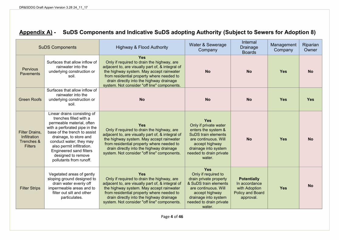
DR&SDDG Draft Appen Version 3.28 24_11_17
Appendix A) - SuDS Components and Indicative SuDS adopting Authority (Subject to Sewers for Adoption 8)
SuDS Components Highway & Flood Authority Water & Sewerage Company
Internal Drainage Boards
Management Company
Riparian Owner
Pervious Pavements
Surfaces that allow inflow of rainwater into the
underlying construction or soil.
Yes
No No Yes No
Only if required to drain the highway, are adjacent to, are visually part of, & integral of the highway system. May accept rainwater from residential property where needed to
drain directly into the highway drainage system. Not consider "off line" components.
Green Roofs
Surfaces that allow inflow of rainwater into the
underlying construction or soil.
No No No Yes Yes
Filter Drains, Infiltration
Trenches & Filters
Linear drains consisting of trenches filled with a
permeable material, often with a perforated pipe in the base of the trench to assist
drainage, to store and conduct water; they may also permit infiltration. Engineered sand filters
designed to remove pollutants from runoff.
Yes Only if required to drain the highway, are
adjacent to, are visually part of, & integral of the highway system. May accept rainwater from residential property where needed to
drain directly into the highway drainage system. Not consider "off line" components.
Yes Only if private water enters the system & SuDS train elements are continuous. Will
accept highway drainage into system
needed to drain private water.
No Yes No
Filter Strips
Vegetated areas of gently sloping ground designed to
drain water evenly off impermeable areas and to
filter out silt and other particulates.
Yes Only if required to drain the highway, are
adjacent to, are visually part of, & integral of the highway system. May accept rainwater from residential property where needed to
drain directly into the highway drainage system. Not consider "off line" components.
Yes
Potentially In accordance with Adoption
Policy and Board approval.
Yes No
Only if required to drain private property
& SuDS train elements are continuous. Will
accept highway drainage into system
needed to drain private water.
Page 4 of 46
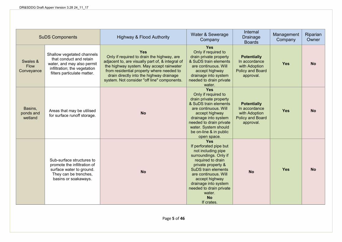
DR&SDDG Draft Appen Version 3.28 24_11_17
SuDS Components Highway & Flood Authority Water & Sewerage Company
Internal Drainage Boards
Management Company
Riparian Owner
Swales & Flow
Conveyance
Shallow vegetated channels that conduct and retain
water, and may also permit infiltration; the vegetation filters particulate matter.
Yes Only if required to drain the highway, are
adjacent to, are visually part of, & integral of the highway system. May accept rainwater from residential property where needed to
drain directly into the highway drainage system. Not consider "off line" components.
Yes Only if required to
drain private property & SuDS train elements
are continuous. Will accept highway
drainage into system needed to drain private
water.
Potentially In accordance with Adoption
Policy and Board approval.
Yes No
Basins, ponds and
wetland
Areas that may be utilised for surface runoff storage. No
Yes Only if required to
drain private property & SuDS train elements
are continuous. Will accept highway
drainage into system needed to drain private water. System should be on-line & in public
open space.
Potentially In accordance with Adoption
Policy and Board approval.
Yes No
Sub-surface structures to promote the infiltration of surface water to ground. They can be trenches, basins or soakaways.
No
Yes If perforated pipe but
not including pipe surroundings. Only if
required to drain private property &
SuDS train elements are continuous. Will
accept highway drainage into system
needed to drain private water.
No If crates.
No Yes No
Page 5 of 46
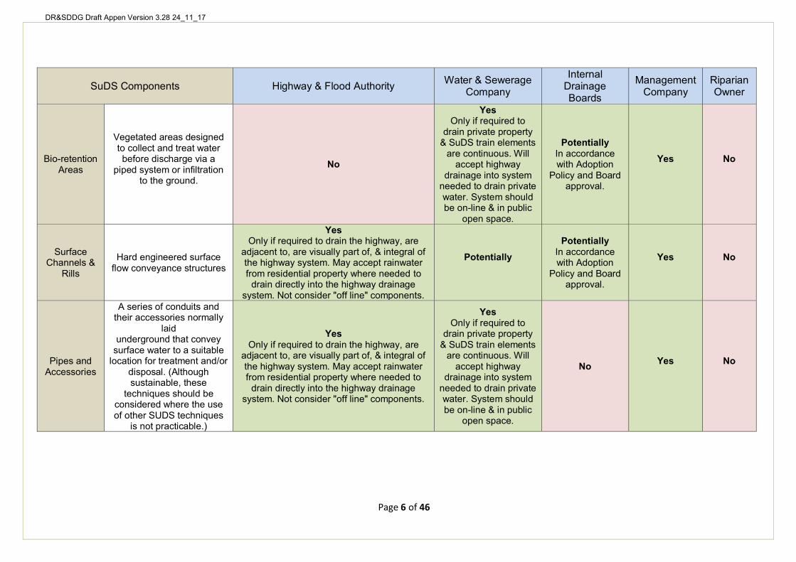
DR&SDDG Draft Appen Version 3.28 24_11_17
SuDS Components Highway & Flood Authority Water & Sewerage Company
Internal Drainage Boards
Management Company
Riparian Owner
Bio-retention Areas
Vegetated areas designed to collect and treat water before discharge via a
piped system or infiltration to the ground.
No
Yes
Potentially In accordance with Adoption
Policy and Board approval.
Yes No
Only if required to drain private property
& SuDS train elements are continuous. Will
accept highway drainage into system
needed to drain private water. System should be on-line & in public
open space.
Surface Channels &
Rills
Hard engineered surface flow conveyance structures
Yes
Potentially
Potentially In accordance with Adoption
Policy and Board approval.
Yes No
Only if required to drain the highway, are adjacent to, are visually part of, & integral of the highway system. May accept rainwater from residential property where needed to
drain directly into the highway drainage system. Not consider "off line" components.
Pipes and Accessories
A series of conduits and their accessories normally
laid underground that convey
surface water to a suitable location for treatment and/or
disposal. (Although sustainable, these
techniques should be considered where the use of other SUDS techniques
is not practicable.)
Yes Only if required to drain the highway, are
adjacent to, are visually part of, & integral of the highway system. May accept rainwater from residential property where needed to
drain directly into the highway drainage system. Not consider "off line" components.
Yes Only if required to
drain private property & SuDS train elements
are continuous. Will accept highway
drainage into system needed to drain private water. System should be on-line & in public
open space.
No Yes No
Page 6 of 46
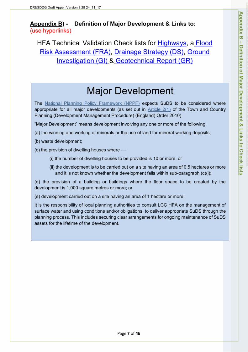
DR&SDDG Draft Appen Version 3.28 24_11_17
Appendix B) - Definition of Major Development & Links to: (use hyperlinks)
HFA Technical Validation Check lists for Highways, a Flood Risk Assessment (FRA), Drainage Strategy (DS), Ground
Investigation (GI) & Geotechnical Report (GR)
Major Development The National Planning Policy Framework (NPPF) expects SuDS to be considered where appropriate for all major developments (as set out in Article 2(1) of the Town and Country Planning (Development Management Procedure) (England) Order 2010)
“Major Development” means development involving any one or more of the following:
(a) the winning and working of minerals or the use of land for mineral-working deposits;
(b) waste development;
(c) the provision of dwelling houses where —
(i) the number of dwelling houses to be provided is 10 or more; or
(ii) the development is to be carried out on a site having an area of 0.5 hectares or more and it is not known whether the development falls within sub-paragraph (c)(i);
(d) the provision of a building or buildings where the floor space to be created by the development is 1,000 square metres or more; or
(e) development carried out on a site having an area of 1 hectare or more;
It is the responsibility of local planning authorities to consult LCC HFA on the management of surface water and using conditions and/or obligations, to deliver appropriate SuDS through the planning process. This includes securing clear arrangements for ongoing maintenance of SuDS assets for the lifetime of the development.
Appendix B
– Definition of M
ajor Developm
ent & Links to C
heck lists
Page 7 of 46

DR&SDDG Draft Appen Version 3.28 24_11_17
Major Development Consultation Requirements & Check lists for Highways,
Flood Risk, SuDS & SW Drainage Essential information (in italics below) is required by HFA at each planning stage or the HFA is likely to “Object” to the Planning Application on the grounds of “lack of
sufficient information provided”. Notes: Reviewed
& accepted
First HFA Contact & Pre Planning (LEVEL 1 - Concept): • HFA Planning Advice Form; • Level 1 FRA; and • Conceptual scheme design (incl. DS).
Outline Planning Permission (LEVEL 2 - Outline): • Highways Information • Level 2 FRA (if risk from local sources exists); • Level 2 Ground Investigation (i.e. infiltration, groundwater, greenfield run-off &
storage volume); • Level 2 Outline Whole Site DS AS PART OF Level 2 Outline Whole Site
Development Layout Plans, Highways, SuDS & Flood Risk Scheme Design proposals;
• Transport Assessment & Travel Plan (for 80+ homes); and • Travel Statement (depending on specific development content)
Note: For further information on the requirements for a TA, TP and TS, please refer to the Lincolnshire Development Roads & Sustainable Drainage Design Approach (DR&SDDA).
Reserved Matters & Full Planning Permission (LEVEL 3 - Detailed): • Highways Information (If not already provided at Outline Planning) • Level 3 FRA (if risk from local sources exists); • Level 3 Detailed Whole Site DS AS PART OF Level 3 Detailed Whole Site
Development Layout Plans, Highways, SuDS & Flood Risk Scheme Design proposals
• Level 3 Detailed Geotechnical Interpretive Report (i.e. infiltration, groundwater, greenfield run-off & storage volume);
• Detailed whole site Landscape Plan; • Whole site Development Construction Management Plan.
If not already provided at Outline Planning, then: • Transport Assessment (TA) & Travel Plan (TP) (for 80+ homes); and • Travel Statement (TS) (depending on specific development content).
Note: If no Outline Application is made, then the Outline Planning requirements above should be also provided. For further information on the requirements for a TA, TP and TS, please refer to the Lincolnshire Development Roads & Sustainable Drainage Design Approach (DR&SDDA).
Appendix B
– HFA
Major D
evelopment C
onsultation Requirem
ents & C
heck lists
Page 8 of 46
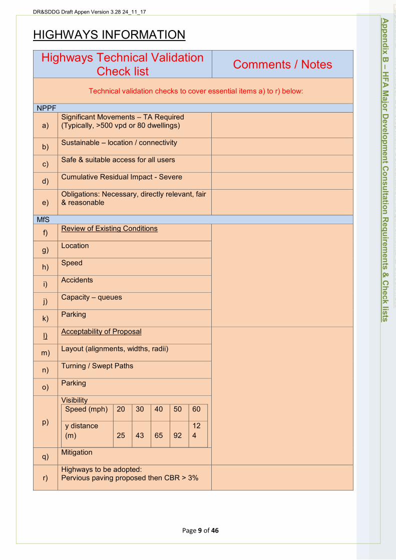
DR&SDDG Draft Appen Version 3.28 24_11_17
HIGHWAYS INFORMATION
Highways Technical Validation Check list Comments / Notes
Technical validation checks to cover essential items a) to r) below:
NPPF
a) Significant Movements – TA Required (Typically, >500 vpd or 80 dwellings)
b) Sustainable – location / connectivity
c) Safe & suitable access for all users
d) Cumulative Residual Impact - Severe
e) Obligations: Necessary, directly relevant, fair & reasonable
MfS
f) Review of Existing Conditions
g) Location
h) Speed
i) Accidents
j) Capacity – queues
k) Parking
l) Acceptability of Proposal
m) Layout (alignments, widths, radii)
n) Turning / Swept Paths
o) Parking
p)
Visibility Speed (mph) 20 30 40 50 60
y distance (m) 25 43 65 92
12 4
q) Mitigation
r) Highways to be adopted: Pervious paving proposed then CBR > 3%
Appendix B
– HFA
Major D
evelopment C
onsultation Requirem
ents & C
heck lists
Page 9 of 46
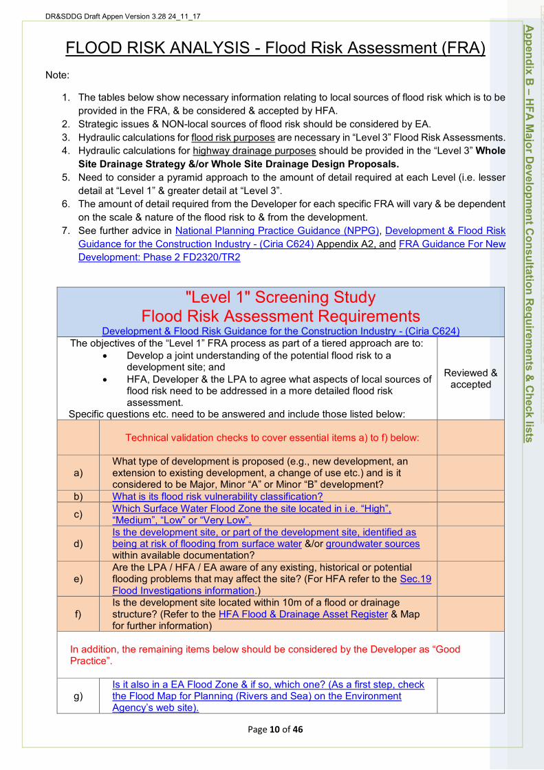
DR&SDDG Draft Appen Version 3.28 24_11_17
FLOOD RISK ANALYSIS - Flood Risk Assessment (FRA) Note:
1. The tables below show necessary information relating to local sources of flood risk which is to be provided in the FRA, & be considered & accepted by HFA.
2. Strategic issues & NON-local sources of flood risk should be considered by EA. 3. Hydraulic calculations for flood risk purposes are necessary in “Level 3” Flood Risk Assessments. 4. Hydraulic calculations for highway drainage purposes should be provided in the “Level 3” Whole
Site Drainage Strategy &/or Whole Site Drainage Design Proposals. 5. Need to consider a pyramid approach to the amount of detail required at each Level (i.e. lesser
detail at “Level 1” & greater detail at “Level 3”. 6. The amount of detail required from the Developer for each specific FRA will vary & be dependent
on the scale & nature of the flood risk to & from the development. 7. See further advice in National Planning Practice Guidance (NPPG), Development & Flood Risk
Guidance for the Construction Industry - (Ciria C624) Appendix A2, and FRA Guidance For New Development: Phase 2 FD2320/TR2
"Level 1" Screening Study Flood Risk Assessment Requirements
Development & Flood Risk Guidance for the Construction Industry - (Ciria C624) The objectives of the “Level 1” FRA process as part of a tiered approach are to:
• Develop a joint understanding of the potential flood risk to a development site; and
• HFA, Developer & the LPA to agree what aspects of local sources of flood risk need to be addressed in a more detailed flood risk assessment.
Specific questions etc. need to be answered and include those listed below:
Reviewed & accepted
Technical validation checks to cover essential items a) to f) below:
a)
b)
c)
What type of development is proposed (e.g., new development, an extension to existing development, a change of use etc.) and is it considered to be Major, Minor “A” or Minor “B” development? What is its flood risk vulnerability classification? Which Surface Water Flood Zone the site located in i.e. “High”, “Medium”, “Low” or “Very Low”.
d) Is the development site, or part of the development site, identified as being at risk of flooding from surface water &/or groundwater sources within available documentation?
e) Are the LPA / HFA / EA aware of any existing, historical or potential flooding problems that may affect the site? (For HFA refer to the Sec.19 Flood Investigations information.)
f) Is the development site located within 10m of a flood or drainage structure? (Refer to the HFA Flood & Drainage Asset Register & Map for further information)
In addition, the remaining items below should be considered by the Developer as “Good Practice”.
g) Is it also in a EA Flood Zone & if so, which one? (As a first step, check the Flood Map for Planning (Rivers and Sea) on the Environment Agency’s web site).
Appendix B
– HFA
Major D
evelopment C
onsultation Requirem
ents & C
heck lists
Page 10 of 46
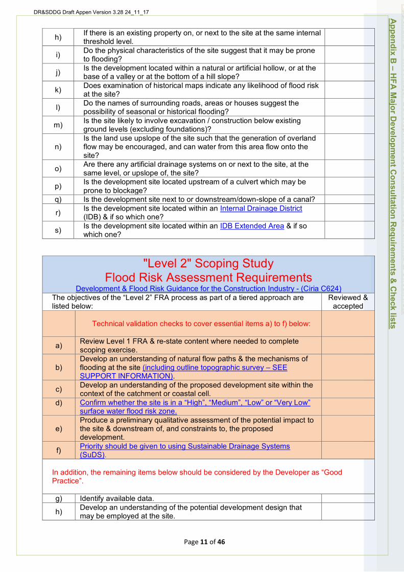
DR&SDDG Draft Appen Version 3.28 24_11_17
h) If there is an existing property on, or next to the site at the same internal threshold level.
i) Do the physical characteristics of the site suggest that it may be prone to flooding?
j) Is the development located within a natural or artificial hollow, or at the base of a valley or at the bottom of a hill slope?
k) Does examination of historical maps indicate any likelihood of flood risk at the site?
l) Do the names of surrounding roads, areas or houses suggest the possibility of seasonal or historical flooding?
m) Is the site likely to involve excavation / construction below existing ground levels (excluding foundations)?
n) Is the land use upslope of the site such that the generation of overland flow may be encouraged, and can water from this area flow onto the site?
o) Are there any artificial drainage systems on or next to the site, at the same level, or upslope of, the site?
p) Is the development site located upstream of a culvert which may be prone to blockage?
q) Is the development site next to or downstream/down-slope of a canal?
r) Is the development site located within an Internal Drainage District (IDB) & if so which one?
s) Is the development site located within an IDB Extended Area & if so which one?
"Level 2" Scoping Study Flood Risk Assessment Requirements
Development & Flood Risk Guidance for the Construction Industry - (Ciria C624) The objectives of the “Level 2” FRA process as part of a tiered approach are listed below:
Reviewed & accepted
Technical validation checks to cover essential items a) to f) below:
a) Review Level 1 FRA & re-state content where needed to complete scoping exercise.
b) Develop an understanding of natural flow paths & the mechanisms of flooding at the site (including outline topographic survey – SEE SUPPORT INFORMATION).
c) Develop an understanding of the proposed development site within the context of the catchment or coastal cell.
d) Confirm whether the site is in a “High”, “Medium”, “Low” or “Very Low” surface water flood risk zone.
e) Produce a preliminary qualitative assessment of the potential impact to the site & downstream of, and constraints to, the proposed development.
f) Priority should be given to using Sustainable Drainage Systems (SuDS).
In addition, the remaining items below should be considered by the Developer as “Good Practice”.
g) Identify available data.
h) Develop an understanding of the potential development design that may be employed at the site.
Appendix B
– HFA
Major D
evelopment C
onsultation Requirem
ents & C
heck lists
Page 11 of 46

DR&SDDG Draft Appen Version 3.28 24_11_17
"Level 3" Detailed Study Flood Risk Assessment Requirements
(NPPF PPG Para 068) A Level 3 FRA is to be undertaken to such a level of detail that an outline design/master plan can be presented to the HFA and LPA for consideration. Specific questions etc. need to be answered and include those listed below:
Reviewed & accepted
a)
Technical validation checks to cover essential items a) to j) below:
Review of Level 1 and 2 FRA & re-consider content where applicable.
b)
c)
Confirm the type of development proposed (e.g., new development, an extension to existing development, a change of use etc.) and where will it be located? Confirm the flood risk vulnerability classification
d) For each identified source, can you describe how flooding would occur, with reference to any historic records where these are available? E.g. Sec.19 Flood Investigations & seek advice.
e) What are the existing surface water drainage arrangements for the site as provided in the Drainage Strategy &/or Detailed Whole Site Drainage Design Proposals?
f) Confirm which EA Flood Zone the site is within? (Check the Flood Map for Planning (Rivers and Sea) on the Environment Agency’s web site).
g) Confirm the probability of the site flooding, taking account of the maps of flood risk from rivers and the sea and from surface water, on the Environment Agency’s web site, and any further flood risk information.
h) The existing rates and volumes of surface water run-off generated by the site, & assessment of the suitability of the receiving watercourse?
i) How is flood risk at the site likely to be affected by climate change? Further information on climate change and development and flood risk is available in the NPPF PG.
j)
Assessment of: • the proposed impacts of the development; • how will the site/building be protected from flooding; & • how you will ensure that your proposed development and the
measures to protect your site from flooding will not increase flood risk elsewhere.
All including the potential impacts of climate change over the development’s lifetime as provided in the Detailed Whole Site Development Layout Plans, Highways, SuDS & Flood Risk Scheme Design Proposals.
In addition, the remaining items below should be considered by the Developer as “Good Practice”.
k)
Modelling where necessary to define the existing flood hazard (e.g. what sources of flooding could affect the site?), including climate change over the lifetime of the development, (including detailed topographic survey – SEE SUPPORT INFORMATION).
l) Are there any opportunities offered by the development to reduce flood risk elsewhere?
m) What flood-related risks will remain after you have implemented the measures to protect the site from flooding?
n) Sensitivity testing to demonstrate that the estimates of flood risk to, & arising from, the site are not overly dependent on the assumed model parameters.
Appendix B
– HFA
Major D
evelopment C
onsultation Requirem
ents & C
heck lists
Page 12 of 46
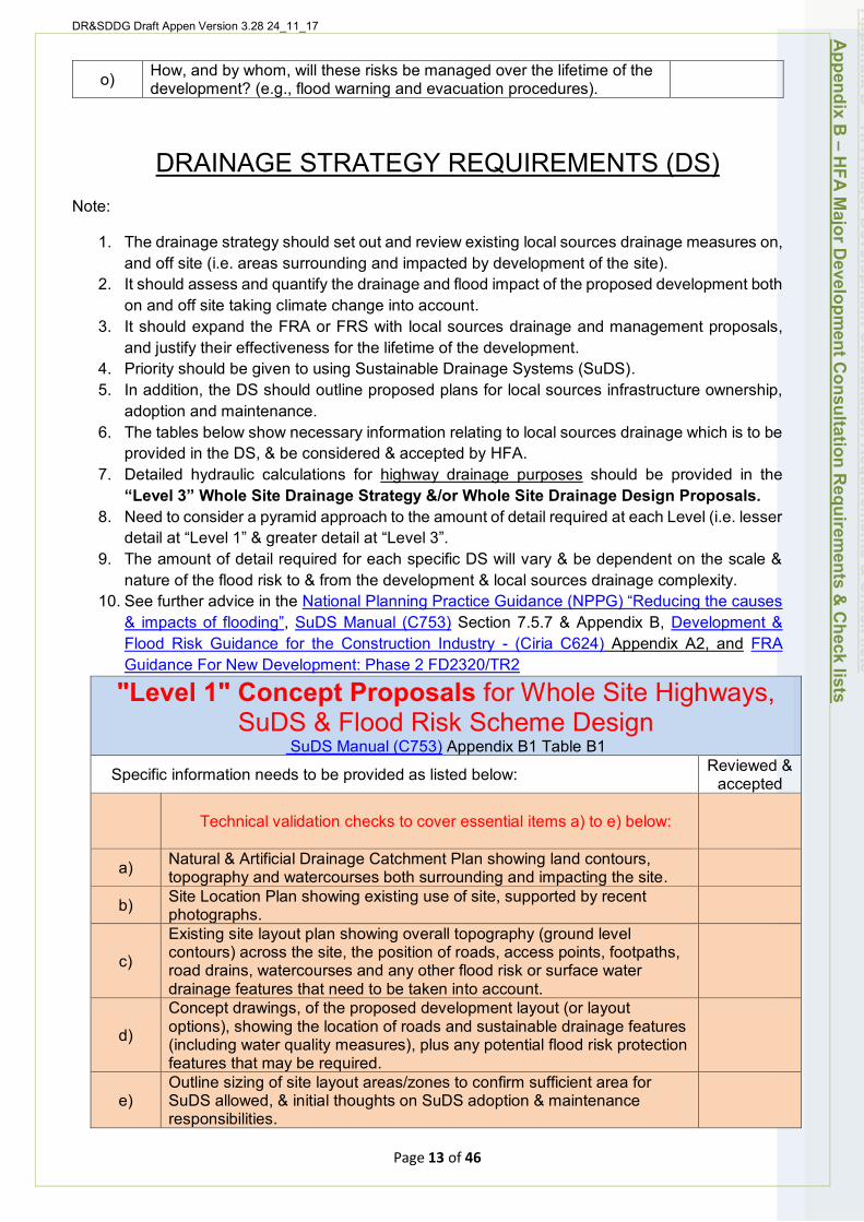
DR&SDDG Draft Appen Version 3.28 24_11_17
o) How, and by whom, will these risks be managed over the lifetime of the development? (e.g., flood warning and evacuation procedures).
DRAINAGE STRATEGY REQUIREMENTS (DS) Note:
1. The drainage strategy should set out and review existing local sources drainage measures on, and off site (i.e. areas surrounding and impacted by development of the site).
2. It should assess and quantify the drainage and flood impact of the proposed development both on and off site taking climate change into account.
3. It should expand the FRA or FRS with local sources drainage and management proposals, and justify their effectiveness for the lifetime of the development.
4. Priority should be given to using Sustainable Drainage Systems (SuDS). 5. In addition, the DS should outline proposed plans for local sources infrastructure ownership,
adoption and maintenance. 6. The tables below show necessary information relating to local sources drainage which is to be
provided in the DS, & be considered & accepted by HFA. 7. Detailed hydraulic calculations for highway drainage purposes should be provided in the
“Level 3” Whole Site Drainage Strategy &/or Whole Site Drainage Design Proposals. 8. Need to consider a pyramid approach to the amount of detail required at each Level (i.e. lesser
detail at “Level 1” & greater detail at “Level 3”. 9. The amount of detail required for each specific DS will vary & be dependent on the scale &
nature of the flood risk to & from the development & local sources drainage complexity. 10. See further advice in the National Planning Practice Guidance (NPPG) “Reducing the causes
& impacts of flooding”, SuDS Manual (C753) Section 7.5.7 & Appendix B, Development & Flood Risk Guidance for the Construction Industry - (Ciria C624) Appendix A2, and FRA Guidance For New Development: Phase 2 FD2320/TR2
"Level 1" Concept Proposals for Whole Site Highways, SuDS & Flood Risk Scheme Design
SuDS Manual (C753) Appendix B1 Table B1
Specific information needs to be provided as listed below: Reviewed & accepted
Technical validation checks to cover essential items a) to e) below:
a) Natural & Artificial Drainage Catchment Plan showing land contours, topography and watercourses both surrounding and impacting the site.
b) Site Location Plan showing existing use of site, supported by recent photographs.
c)
Existing site layout plan showing overall topography (ground level contours) across the site, the position of roads, access points, footpaths, road drains, watercourses and any other flood risk or surface water drainage features that need to be taken into account.
d)
Concept drawings, of the proposed development layout (or layout options), showing the location of roads and sustainable drainage features (including water quality measures), plus any potential flood risk protection features that may be required.
e) Outline sizing of site layout areas/zones to confirm sufficient area for SuDS allowed, & initial thoughts on SuDS adoption & maintenance responsibilities.
Appendix B
– HFA
Major D
evelopment C
onsultation Requirem
ents & C
heck lists
Page 13 of 46
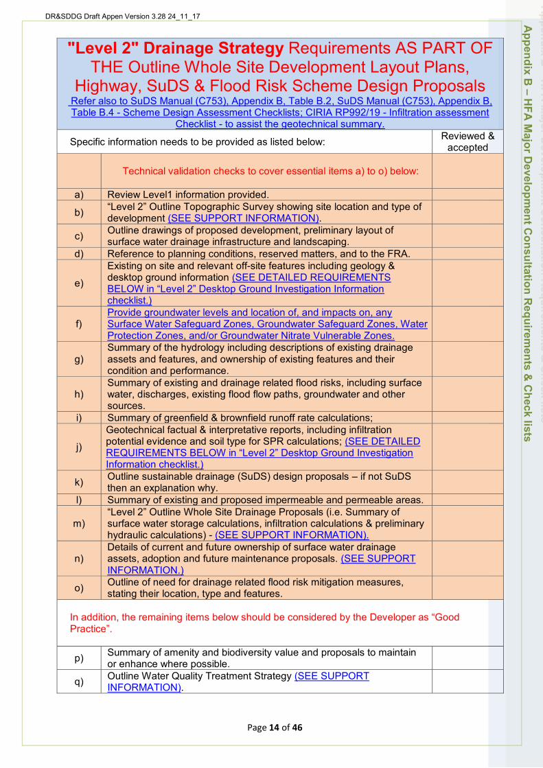
DR&SDDG Draft Appen Version 3.28 24_11_17
"Level 2" Drainage Strategy Requirements AS PART OF THE Outline Whole Site Development Layout Plans,
Highway, SuDS & Flood Risk Scheme Design Proposals Refer also to SuDS Manual (C753), Appendix B, Table B.2, SuDS Manual (C753), Appendix B, Table B.4 - Scheme Design Assessment Checklists; CIRIA RP992/19 - Infiltration assessment
Checklist - to assist the geotechnical summary.
Specific information needs to be provided as listed below: Reviewed & accepted
a)
Technical validation checks to cover essential items a) to o) below:
Review Level1 information provided.
b) “Level 2” Outline Topographic Survey showing site location and type of development (SEE SUPPORT INFORMATION).
c)
d)
Outline drawings of proposed development, preliminary layout of surface water drainage infrastructure and landscaping. Reference to planning conditions, reserved matters, and to the FRA.
e)
Existing on site and relevant off-site features including geology & desktop ground information (SEE DETAILED REQUIREMENTS BELOW in “Level 2” Desktop Ground Investigation Information checklist.)
f) Provide groundwater levels and location of, and impacts on, any Surface Water Safeguard Zones, Groundwater Safeguard Zones, Water Protection Zones, and/or Groundwater Nitrate Vulnerable Zones.
g) Summary of the hydrology including descriptions of existing drainage assets and features, and ownership of existing features and their condition and performance.
h)
i)
Summary of existing and drainage related flood risks, including surface water, discharges, existing flood flow paths, groundwater and other sources. Summary of greenfield & brownfield runoff rate calculations;
j)
Geotechnical factual & interpretative reports, including infiltration potential evidence and soil type for SPR calculations; (SEE DETAILED REQUIREMENTS BELOW in “Level 2” Desktop Ground Investigation Information checklist.)
k)
l)
Outline sustainable drainage (SuDS) design proposals – if not SuDS then an explanation why. Summary of existing and proposed impermeable and permeable areas.
m) “Level 2” Outline Whole Site Drainage Proposals (i.e. Summary of surface water storage calculations, infiltration calculations & preliminary hydraulic calculations) - (SEE SUPPORT INFORMATION).
n) Details of current and future ownership of surface water drainage assets, adoption and future maintenance proposals. (SEE SUPPORT INFORMATION.)
o) Outline of need for drainage related flood risk mitigation measures, stating their location, type and features.
In addition, the remaining items below should be considered by the Developer as “Good Practice”.
p) Summary of amenity and biodiversity value and proposals to maintain or enhance where possible.
q) Outline Water Quality Treatment Strategy (SEE SUPPORT INFORMATION).
Appendix B
– HFA
Major D
evelopment C
onsultation Requirem
ents & C
heck lists
Page 14 of 46
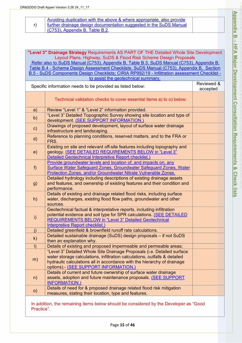
DR&SDDG Draft Appen Version 3.28 24_11_17
r) Avoiding duplication with the above & where appropriate, also provide further drainage design documentation suggested in the SuDS Manual (C753), Appendix B, Table B.2.
"Level 3" Drainage Strategy Requirements AS PART OF THE Detailed Whole Site Development Layout Plans, Highway, SuDS & Flood Risk Scheme Design Proposals
Refer also to SuDS Manual (C753), Appendix B, Table B.3, SuDS Manual (C753), Appendix B, Table B.4 - Scheme Design Assessment Checklists; SuDS Manual (C753), Appendix B, Section B.5 - SuDS Components Design Checklists; CIRIA RP992/19 - Infiltration assessment Checklist -
to assist the geotechnical summary.
Specific information needs to be provided as listed below: Reviewed & accepted
Technical validation checks to cover essential items a) to o) below:
a) Review “Level 1” & “Level 2” information provided.
b) “Level 3” Detailed Topographic Survey showing site location and type of development. (SEE SUPPORT INFORMATION.)
c) Drawings of proposed development, layout of surface water drainage infrastructure and landscaping.
d) Reference to planning conditions, reserved matters, and to the FRA or FRS.
e) Existing on site and relevant off-site features including topography and geology. (SEE DETAILED REQUIREMENTS BELOW in “Level 3” Detailed Geotechnical Interpretive Report checklist.)
f) Provide groundwater levels and location of, and impacts on, any Surface Water Safeguard Zones, Groundwater Safeguard Zones, Water Protection Zones, and/or Groundwater Nitrate Vulnerable Zones.
g) Detailed hydrology including descriptions of existing drainage assets and features, and ownership of existing features and their condition and performance.
h) Details of existing and drainage related flood risks, including surface water, discharges, existing flood flow paths, groundwater and other sources.
i)
Geotechnical factual & interpretative reports, including infiltration potential evidence and soil type for SPR calculations. (SEE DETAILED REQUIREMENTS BELOW in “Level 3” Detailed Geotechnical Interpretive Report checklist.)
j) Detailed greenfield & brownfield runoff rate calculations.
k) Detailed sustainable drainage (SuDS) design proposals – if not SuDS then an explanation why.
l) Details of existing and proposed impermeable and permeable areas;
m)
“Level 3” Detailed Whole Site Drainage Proposals (i.e. Detailed surface water storage calculations, infiltration calculations, outfalls & detailed hydraulic calculations all in accordance with the hierarchy of drainage options).- (SEE SUPPORT INFORMATION.)
n) Details of current and future ownership of surface water drainage assets, adoption and future maintenance proposals. (SEE SUPPORT INFORMATION.)
o) Details of need for & proposed drainage related flood risk mitigation measures, stating their location, type and features.
In addition, the remaining items below should be considered by the Developer as “Good Practice”.
Appendix B
– HFA
Major D
evelopment C
onsultation Requirem
ents & C
heck lists
Page 15 of 46
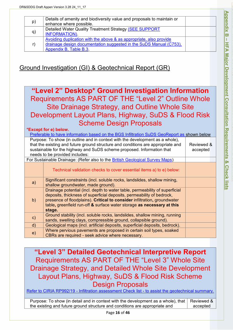
DR&SDDG Draft Appen Version 3.28 24_11_17
“Level 2” Desktop* Ground Investigation Information Requirements AS PART OF THE “Level 2” Outline Whole
Site Drainage Strategy, and Outline Whole Site Development Layout Plans, Highway, SuDS & Flood Risk
Scheme Design Proposals *Except for e) below.
Preferable to have information based on the BGS Infiltration SuDS GeoReport as shown below Purpose: To show (in outline and in context with the development as a whole), that the existing and future ground structure and conditions are appropriate and sustainable for the highway and SuDS scheme proposed. Information that needs to be provided includes:
Reviewed & accepted
For Sustainable Drainage: (Refer also to the British Geological Survey Maps)
Technical validation checks to cover essential items a) to e) below:
a) Significant constraints (incl. soluble rocks, landslides, shallow mining, shallow groundwater, made ground).
b)
Drainage potential (incl. depth to water table, permeability of superficial deposits, thickness of superficial deposits, permeability of bedrock, presence of floodplains). Critical to consider infiltration, groundwater table, greenfield run-off & surface water storage as necessary at this stage.
c) Ground stability (incl. soluble rocks, landslides, shallow mining, running sands, swelling clays, compressible ground, collapsible ground).
d) Geological maps (incl. artificial deposits, superficial deposits, bedrock).
e) Where pervious pavements are proposed in certain soil types, soaked CBRs are required - seek advice where necessary.
“Level 3” Detailed Geotechnical Interpretive Report Requirements AS PART OF THE “Level 3” Whole Site
Drainage Strategy, and Detailed Whole Site Development Layout Plans, Highway, SuDS & Flood Risk Scheme
Design Proposals Refer to CIRIA RP992/19 - Infiltration assessment Check list - to assist the geotechnical summary.
Appendix B
– HFA
Major D
evelopment C
onsultation Requirem
ents & C
heck lists
p)
q)
r)
Details of amenity and biodiversity value and proposals to maintain or enhance where possible. Detailed Water Quality Treatment Strategy (SEE SUPPORT INFORMATION). Avoiding duplication with the above & as appropriate, also provide drainage design documentation suggested in the SuDS Manual (C753), Appendix B, Table B.3.
Ground Investigation (GI) & Geotechnical Report (GR)
Purpose: To show (in detail and in context with the development as a whole), that Reviewed & the existing and future ground structure and conditions are appropriate and accepted
Page 16 of 46

DR&SDDG Draft Appen Version 3.28 24_11_17
sustainable for the highway and SuDS scheme proposed. Information that needs to be provided includes:
For Sustainable Drainage: (Refer also to the British Geological Survey Maps)
Technical validation checks to cover essential items a) to d) below:
a) Build on Desktop Ground Investigation.
b) Detailed infiltration assessment (incl. evidence soil types & infiltration coefficients) i.e. BRE Digest 365
c) Where possible, detailed evidence of groundwater table levels over recent 12-month period or other validated evidence.
d) Where pervious pavements are proposed in certain soil types, soaked CBRs are required - seek advice where necessary.
Appendix B
– HFA
Major D
evelopment C
onsultation Requirem
ents & C
heck lists
Page 17 of 46
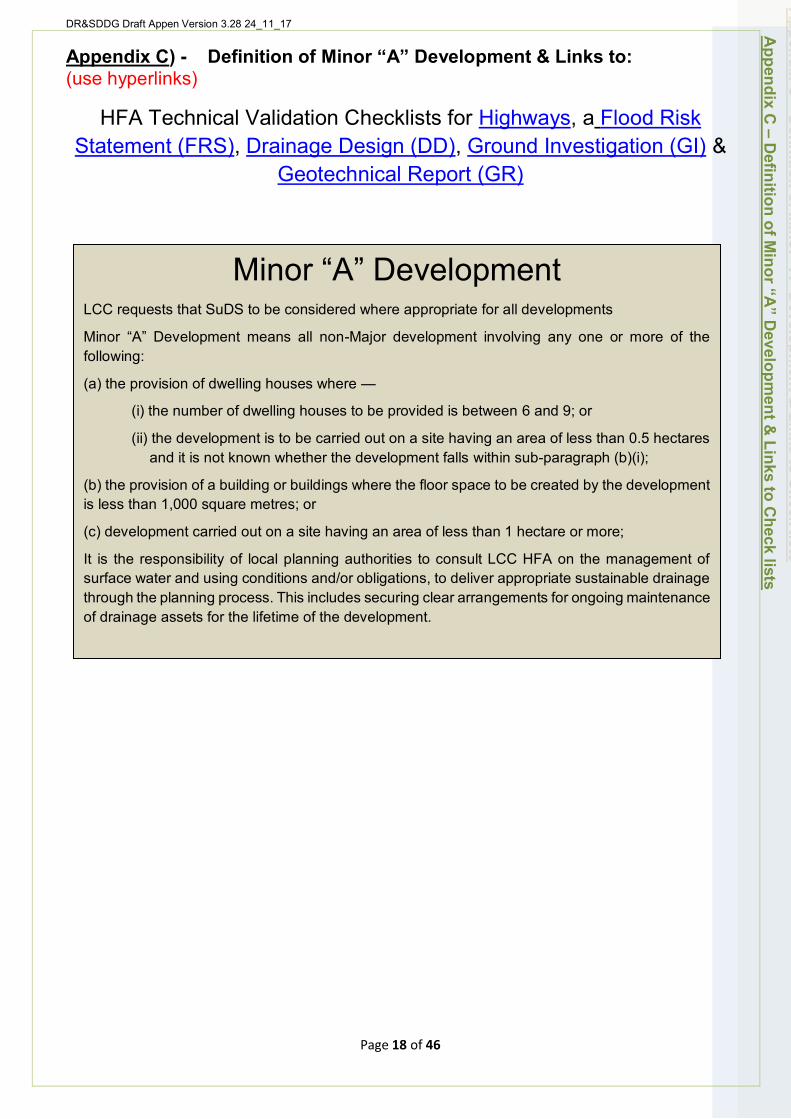
DR&SDDG Draft Appen Version 3.28 24_11_17
Appendix C) - Definition of Minor “A” Development & Links to: (use hyperlinks)
HFA Technical Validation Checklists for Highways, a Flood Risk Statement (FRS), Drainage Design (DD), Ground Investigation (GI) &
Geotechnical Report (GR)
Minor “A” Development LCC requests that SuDS to be considered where appropriate for all developments
Minor “A” Development means all non-Major development involving any one or more of the following:
(a) the provision of dwelling houses where —
(i) the number of dwelling houses to be provided is between 6 and 9; or
(ii) the development is to be carried out on a site having an area of less than 0.5 hectares and it is not known whether the development falls within sub-paragraph (b)(i);
(b) the provision of a building or buildings where the floor space to be created by the development is less than 1,000 square metres; or
(c) development carried out on a site having an area of less than 1 hectare or more;
It is the responsibility of local planning authorities to consult LCC HFA on the management of surface water and using conditions and/or obligations, to deliver appropriate sustainable drainage through the planning process. This includes securing clear arrangements for ongoing maintenance of drainage assets for the lifetime of the development.
Appendix C
– Definition of M
inor “A” D
evelopment &
Links to Check lists
Page 18 of 46
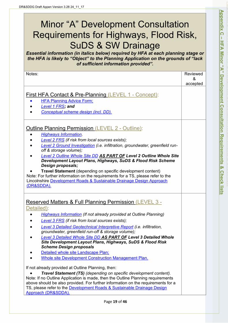
DR&SDDG Draft Appen Version 3.28 24_11_17
Minor “A” Development Consultation Requirements for Highways, Flood Risk,
SuDS & SW Drainage Essential information (in italics below) required by HFA at each planning stage or the HFA is likely to “Object” to the Planning Application on the grounds of “lack
of sufficient information provided”.
Notes: Reviewed &
accepted
First HFA Contact & Pre-Planning (LEVEL 1 - Concept): • HFA Planning Advice Form; • Level 1 FRS; and • Conceptual scheme design (incl. DD).
Outline Planning Permission (LEVEL 2 - Outline): • Highways Information. • Level 2 FRS (if risk from local sources exists); • Level 2 Ground Investigation (i.e. infiltration, groundwater, greenfield run-
off & storage volume); • Level 2 Outline Whole Site DD AS PART OF Level 2 Outline Whole Site
Development Layout Plans, Highways, SuDS & Flood Risk Scheme Design proposals;
• Travel Statement (depending on specific development content) Note: For further information on the requirements for a TS, please refer to the Lincolnshire Development Roads & Sustainable Drainage Design Approach (DR&SDDA).
Reserved Matters & Full Planning Permission (LEVEL 3 -Detailed): • Highways Information (If not already provided at Outline Planning) • Level 3 FRS (if risk from local sources exists); • Level 3 Detailed Geotechnical Interpretive Report (i.e. infiltration,
groundwater, greenfield run-off & storage volume); • Level 3 Detailed Whole Site DD AS PART OF Level 3 Detailed Whole
Site Development Layout Plans, Highways, SuDS & Flood Risk Scheme Design proposals
• Detailed whole site Landscape Plan; • Whole site Development Construction Management Plan.
If not already provided at Outline Planning, then: • Travel Statement (TS) (depending on specific development content).
Note: If no Outline Application is made, then the Outline Planning requirements above should be also provided. For further information on the requirements for a TS, please refer to the Development Roads & Sustainable Drainage Design Approach (DR&SDDA).
Appendix C
– HFA
Minor “A
” Developm
ent Consultation R
equirements &
Check lists
Page 19 of 46
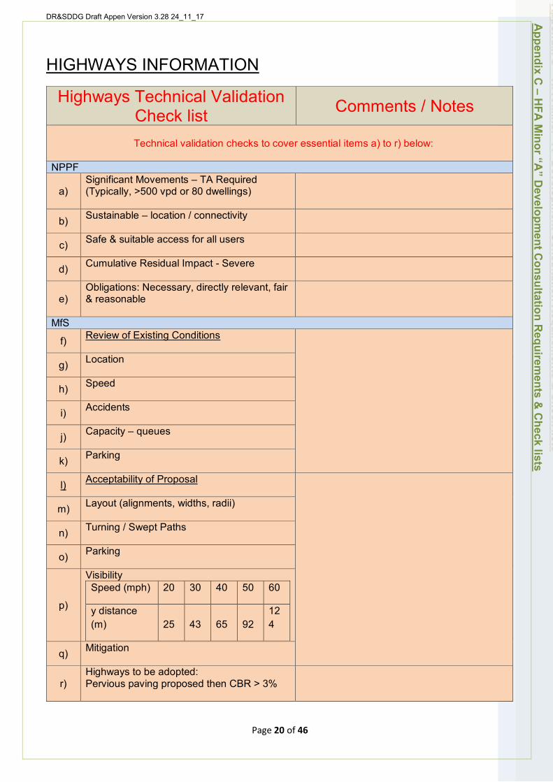
DR&SDDG Draft Appen Version 3.28 24_11_17
HIGHWAYS INFORMATION
Highways Technical Validation Check list Comments / Notes
Technical validation checks to cover essential items a) to r) below:
NPPF
a) Significant Movements – TA Required (Typically, >500 vpd or 80 dwellings)
b) Sustainable – location / connectivity
c) Safe & suitable access for all users
d) Cumulative Residual Impact - Severe
e) Obligations: Necessary, directly relevant, fair & reasonable
MfS
f) Review of Existing Conditions
g) Location
h) Speed
i) Accidents
j) Capacity – queues
k) Parking
l) Acceptability of Proposal
m) Layout (alignments, widths, radii)
n) Turning / Swept Paths
o) Parking
p)
Visibility Speed (mph) 20 30 40 50 60
y distance (m) 25 43 65 92
12 4
q) Mitigation
r) Highways to be adopted: Pervious paving proposed then CBR > 3%
Appendix C
– HFA
Minor “A
” Developm
ent Consultation R
equirements &
Check lists
Page 20 of 46
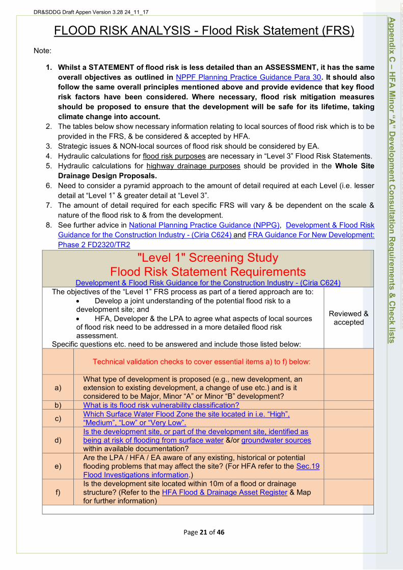
DR&SDDG Draft Appen Version 3.28 24_11_17
FLOOD RISK ANALYSIS - Flood Risk Statement (FRS) Note:
1. Whilst a STATEMENT of flood risk is less detailed than an ASSESSMENT, it has the same overall objectives as outlined in NPPF Planning Practice Guidance Para 30. It should also follow the same overall principles mentioned above and provide evidence that key flood risk factors have been considered. Where necessary, flood risk mitigation measures should be proposed to ensure that the development will be safe for its lifetime, taking climate change into account.
2. The tables below show necessary information relating to local sources of flood risk which is to be provided in the FRS, & be considered & accepted by HFA.
3. Strategic issues & NON-local sources of flood risk should be considered by EA. 4. Hydraulic calculations for flood risk purposes are necessary in “Level 3” Flood Risk Statements. 5. Hydraulic calculations for highway drainage purposes should be provided in the Whole Site
Drainage Design Proposals. 6. Need to consider a pyramid approach to the amount of detail required at each Level (i.e. lesser
detail at “Level 1” & greater detail at “Level 3”. 7. The amount of detail required for each specific FRS will vary & be dependent on the scale &
nature of the flood risk to & from the development. 8. See further advice in National Planning Practice Guidance (NPPG), Development & Flood Risk
Guidance for the Construction Industry - (Ciria C624) and FRA Guidance For New Development: Phase 2 FD2320/TR2
"Level 1" Screening Study Flood Risk Statement Requirements
Development & Flood Risk Guidance for the Construction Industry - (Ciria C624) The objectives of the “Level 1” FRS process as part of a tiered approach are to:
• Develop a joint understanding of the potential flood risk to a development site; and • HFA, Developer & the LPA to agree what aspects of local sources of flood risk need to be addressed in a more detailed flood risk assessment.
Specific questions etc. need to be answered and include those listed below:
Reviewed & accepted
Technical validation checks to cover essential items a) to f) below:
a)
b)
What type of development is proposed (e.g., new development, an extension to existing development, a change of use etc.) and is it considered to be Major, Minor “A” or Minor “B” development? What is its flood risk vulnerability classification?
c) Which Surface Water Flood Zone the site located in i.e. “High”, “Medium”, “Low” or “Very Low”.
d) Is the development site, or part of the development site, identified as being at risk of flooding from surface water &/or groundwater sources within available documentation?
e) Are the LPA / HFA / EA aware of any existing, historical or potential flooding problems that may affect the site? (For HFA refer to the Sec.19 Flood Investigations information.)
f) Is the development site located within 10m of a flood or drainage structure? (Refer to the HFA Flood & Drainage Asset Register & Map for further information)
Appendix C
– HFA
Minor “A
” Developm
ent Consultation R
equirements &
Check lists
Page 21 of 46
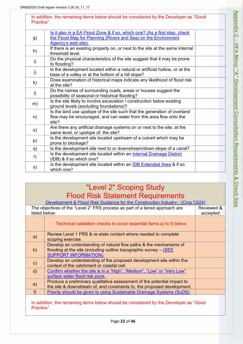
DR&SDDG Draft Appen Version 3.28 24_11_17
In addition, the remaining items below should be considered by the Developer as “Good Practice”.
g) Is it also in a EA Flood Zone & if so, which one? (As a first step, check the Flood Map for Planning (Rivers and Sea) on the Environment Agency’s web site).
h) If there is an existing property on, or next to the site at the same internal threshold level.
i) Do the physical characteristics of the site suggest that it may be prone to flooding?
j) Is the development located within a natural or artificial hollow, or at the base of a valley or at the bottom of a hill slope?
k) Does examination of historical maps indicate any likelihood of flood risk at the site?
l) Do the names of surrounding roads, areas or houses suggest the possibility of seasonal or historical flooding?
m) Is the site likely to involve excavation / construction below existing ground levels (excluding foundations)?
n) Is the land use upslope of the site such that the generation of overland flow may be encouraged, and can water from this area flow onto the site?
o) Are there any artificial drainage systems on or next to the site, at the same level, or upslope of, the site?
p) Is the development site located upstream of a culvert which may be prone to blockage?
q) Is the development site next to or downstream/down-slope of a canal?
r) Is the development site located within an Internal Drainage District (IDB) & if so which one?
s) Is the development site located within an IDB Extended Area & if so which one?
Page 22 of 46
"Level 2" Scoping Study Flood Risk Statement Requirements
Development & Flood Risk Guidance for the Construction Industry - (Ciria C624) The objectives of the “Level 2” FRS process as part of a tiered approach are listed below:
Reviewed & accepted
Technical validation checks to cover essential items a) to f) below:
a) Review Level 1 FRS & re-state content where needed to complete scoping exercise.
b) Develop an understanding of natural flow paths & the mechanisms of flooding at the site (including outline topographic survey – (SEE SUPPORT INFORMATION).
c) Develop an understanding of the proposed development site within the context of the catchment or coastal cell.
d) Confirm whether the site is in a “High”, “Medium”, “Low” or “Very Low” surface water flood risk zone.
e) Produce a preliminary qualitative assessment of the potential impact to the site & downstream of, and constraints to, the proposed development.
f) Priority should be given to using Sustainable Drainage Systems (SuDS).
In addition, the remaining items below should be considered by the Developer as “Good Practice”.
Appendix C
– HFA
Minor “A
” Developm
ent Consultation R
equirements &
Check lists
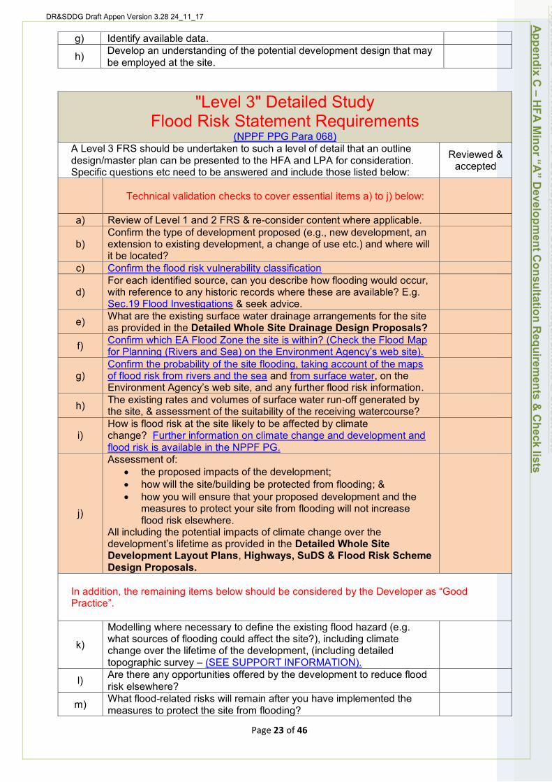
DR&SDDG Draft Appen Version 3.28 24_11_17
g) Identify available data.
h) Develop an understanding of the potential development design that may be employed at the site.
"Level 3" Detailed Study Flood Risk Statement Requirements
(NPPF PPG Para 068) A Level 3 FRS should be undertaken to such a level of detail that an outline design/master plan can be presented to the HFA and LPA for consideration. Specific questions etc need to be answered and include those listed below:
Reviewed & accepted
a)
Technical validation checks to cover essential items a) to j) below:
Review of Level 1 and 2 FRS & re-consider content where applicable.
b)
c)
Confirm the type of development proposed (e.g., new development, an extension to existing development, a change of use etc.) and where will it be located? Confirm the flood risk vulnerability classification
d) For each identified source, can you describe how flooding would occur, with reference to any historic records where these are available? E.g. Sec.19 Flood Investigations & seek advice.
e) What are the existing surface water drainage arrangements for the site as provided in the Detailed Whole Site Drainage Design Proposals?
f) Confirm which EA Flood Zone the site is within? (Check the Flood Map for Planning (Rivers and Sea) on the Environment Agency’s web site).
g) Confirm the probability of the site flooding, taking account of the maps of flood risk from rivers and the sea and from surface water, on the Environment Agency’s web site, and any further flood risk information.
h) The existing rates and volumes of surface water run-off generated by the site, & assessment of the suitability of the receiving watercourse?
i) How is flood risk at the site likely to be affected by climate change? Further information on climate change and development and flood risk is available in the NPPF PG.
j)
Assessment of: • the proposed impacts of the development; • how will the site/building be protected from flooding; & • how you will ensure that your proposed development and the
measures to protect your site from flooding will not increase flood risk elsewhere.
All including the potential impacts of climate change over the development’s lifetime as provided in the Detailed Whole Site Development Layout Plans, Highways, SuDS & Flood Risk Scheme Design Proposals.
In addition, the remaining items below should be considered by the Developer as “Good Practice”.
k)
Modelling where necessary to define the existing flood hazard (e.g. what sources of flooding could affect the site?), including climate change over the lifetime of the development, (including detailed topographic survey – (SEE SUPPORT INFORMATION).
l) Are there any opportunities offered by the development to reduce flood risk elsewhere?
m) What flood-related risks will remain after you have implemented the measures to protect the site from flooding?
Appendix C
– HFA
Minor “A
” Developm
ent Consultation R
equirements &
Check lists
Page 23 of 46

DR&SDDG Draft Appen Version 3.28 24_11_17
Sensitivity testing to demonstrate that the estimates of flood risk to, & n) arising from, the site are not overly dependent on the assumed model
parameters. How, and by whom, will these risks be managed over the lifetime of the o) development? (e.g., flood warning and evacuation procedures).
DRAINAGE DETAIL REQUIREMENTS (DD) Note:
1. The drainage detail should set out and review existing local sources drainage measures on, and off site (i.e. areas surrounding and impacted by development of the site).
2. It should assess and quantify the drainage and flood impact of the proposed development both on and off site taking climate change into account.
3. It should expand the FRS with local sources drainage and management proposals, and justify their effectiveness for the lifetime of the development.
4. Priority should be given to using Sustainable Drainage Systems (SuDS). 5. In addition, the DD should outline proposed plans for local sources infrastructure ownership,
adoption and maintenance. 6. The tables below show necessary information relating to local sources drainage which is to be
provided in the DD, & be considered & accepted by HFA. 7. Detailed hydraulic calculations for highway drainage purposes should be provided in the “Level
3” Whole Site Drainage Design Proposals. 8. Need to consider a pyramid approach to the amount of detail required at each Level (i.e. lesser
detail at “Level 1” & greater detail at “Level 3”. 9. The amount of detail required for each specific DD will vary & be dependent on the scale & nature
of the flood risk to & from the development & local sources drainage complexity. 10. See further advice in the National Planning Practice Guidance (NPPG) “Reducing the causes &
impacts of flooding”, SuDS Manual (C753) Section 7.5.7 & Appendix B, Development & Flood Risk Guidance for the Construction Industry - (Ciria C624)
"Level 1" Concept Proposals for Whole Site Highways, SuDS / SW Drainage & Flood Risk Scheme Design
Refer also to SuDS Manual (C753), Appendix B, Table B.1
Specific information needs to be provided as listed below: Reviewed & accepted
Technical validation checks to cover essential items a) to e) below:
a) Natural & Artificial Drainage Catchment Plan showing land contours, topography and watercourses both surrounding and impacting the site.
b) Site Location Plan showing existing use of site, supported by recent photographs.
c)
Existing site layout plan showing overall topography (ground level contours) across the site, the position of roads, access points, footpaths, road drains, watercourses and any other flood risk or surface water drainage features that need to be taken into account.
d) Concept drawings, of the proposed development layout (or layout options), showing the location of roads and sustainable drainage features
Appendix C
– HFA
Minor “A
” Developm
ent Consultation R
equirements &
Check lists
Page 24 of 46

DR&SDDG Draft Appen Version 3.28 24_11_17
(including water quality measures), plus any potential flood risk protection features that may be required.
e) Outline sizing of site layout areas/zones to confirm sufficient area for SuDS allowed, & initial thoughts on SuDS adoption & maintenance responsibilities.
"Level 2" Drainage Detail Requirements AS PART OF THE Outline Whole Site Development Layout Plans,
Highway, SuDS / SW Drainage & Flood Risk Scheme Design Proposals
Refer also to SuDS Manual (C753), Appendix B, Table B.2, SuDS Manual (C753), Appendix B, Table B.4 - Scheme Design Assessment Checklists; CIRIA RP992/19 - Infiltration assessment
Checklist - to assist the geotechnical summary.
Specific information needs to be provided as listed below: Reviewed & accepted
a)
Technical validation checks to cover essential items a) to o) below:
Review Level1 information provided.
b) “Level 2” Outline Topographic Survey showing site location and type of development (SEE SUPPORT INFORMATION).
c)
d)
Outline drawings of proposed development, preliminary layout of surface water drainage infrastructure and landscaping. Reference to planning conditions, reserved matters, and to the FRA.
e) Existing on site and relevant off-site features including geology & desktop ground information (SEE DETAILED REQUIREMENTS BELOW).
f) Provide groundwater levels and location of, and impacts on, any Surface Water Safeguard Zones, Groundwater Safeguard Zones, Water Protection Zones, and/or Groundwater Nitrate Vulnerable Zones.
g) Summary of the hydrology including descriptions of existing drainage assets and features, and ownership of existing features and their condition and performance.
h)
i)
Summary of existing and drainage related flood risks, including surface water, discharges, existing flood flow paths, groundwater and other sources. Summary of greenfield & brownfield runoff rate calculations;
j) Geotechnical factual & interpretative reports, including infiltration potential evidence and soil type for SPR calculations; (SEE DETAILED REQUIREMENTS BELOW).
k)
l)
Outline sustainable drainage (SuDS) design proposals – if not SuDS then an explanation why. Summary of existing and proposed impermeable and permeable areas.
m) “Level 2” Outline Whole Site Drainage Proposals (i.e. Summary of surface water storage calculations, infiltration calculations & preliminary hydraulic calculations) - (SEE SUPPORT INFORMATION).
n) Details of current and future ownership of surface water drainage assets, adoption and future maintenance proposals. (SEE SUPPORT INFORMATION.)
o) Outline of need for drainage related flood risk mitigation measures, stating their location, type and features.
Appendix C
– HFA
Minor “A
” Developm
ent Consultation R
equirements &
Check lists
Page 25 of 46
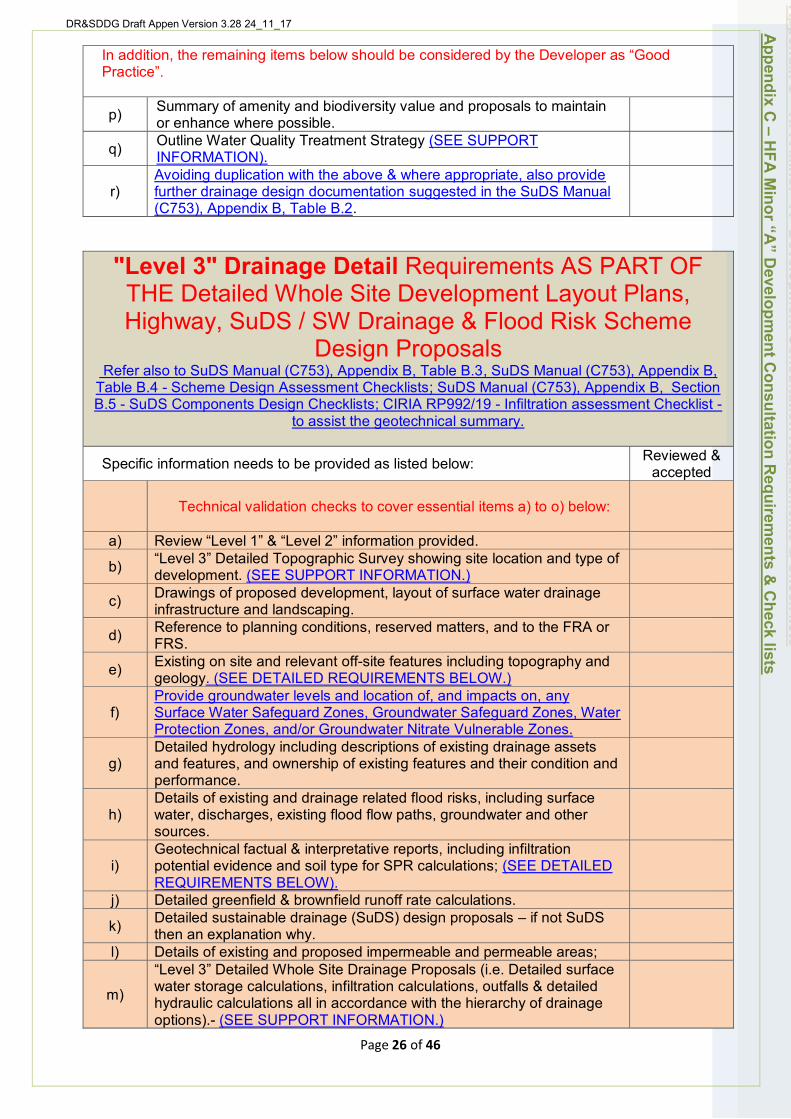
DR&SDDG Draft Appen Version 3.28 24_11_17
In addition, the remaining items below should be considered by the Developer as “Good Practice”.
p) Summary of amenity and biodiversity value and proposals to maintain or enhance where possible.
q) Outline Water Quality Treatment Strategy (SEE SUPPORT INFORMATION).
r) Avoiding duplication with the above & where appropriate, also provide further drainage design documentation suggested in the SuDS Manual (C753), Appendix B, Table B.2.
"Level 3" Drainage Detail Requirements AS PART OF THE Detailed Whole Site Development Layout Plans, Highway, SuDS / SW Drainage & Flood Risk Scheme
Design Proposals Refer also to SuDS Manual (C753), Appendix B, Table B.3, SuDS Manual (C753), Appendix B,
Table B.4 - Scheme Design Assessment Checklists; SuDS Manual (C753), Appendix B, Section B.5 - SuDS Components Design Checklists; CIRIA RP992/19 - Infiltration assessment Checklist -
to assist the geotechnical summary.
Specific information needs to be provided as listed below: Reviewed & accepted
a)
Technical validation checks to cover essential items a) to o) below:
Review “Level 1” & “Level 2” information provided.
b) “Level 3” Detailed Topographic Survey showing site location and type of development. (SEE SUPPORT INFORMATION.)
c) Drawings of proposed development, layout of surface water drainage infrastructure and landscaping.
d) Reference to planning conditions, reserved matters, and to the FRA or FRS.
e) Existing on site and relevant off-site features including topography and geology. (SEE DETAILED REQUIREMENTS BELOW.)
f) Provide groundwater levels and location of, and impacts on, any Surface Water Safeguard Zones, Groundwater Safeguard Zones, Water Protection Zones, and/or Groundwater Nitrate Vulnerable Zones.
g) Detailed hydrology including descriptions of existing drainage assets and features, and ownership of existing features and their condition and performance.
h) Details of existing and drainage related flood risks, including surface water, discharges, existing flood flow paths, groundwater and other sources.
i)
j)
Geotechnical factual & interpretative reports, including infiltration potential evidence and soil type for SPR calculations; (SEE DETAILED REQUIREMENTS BELOW). Detailed greenfield & brownfield runoff rate calculations.
k)
l)
Detailed sustainable drainage (SuDS) design proposals – if not SuDS then an explanation why. Details of existing and proposed impermeable and permeable areas;
m)
“Level 3” Detailed Whole Site Drainage Proposals (i.e. Detailed surface water storage calculations, infiltration calculations, outfalls & detailed hydraulic calculations all in accordance with the hierarchy of drainage options).- (SEE SUPPORT INFORMATION.)
Appendix C
– HFA
Minor “A
” Developm
ent Consultation R
equirements &
Check lists
Page 26 of 46
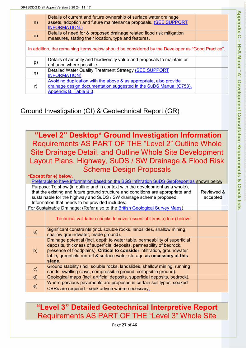
DR&SDDG Draft Appen Version 3.28 24_11_17
Details of current and future ownership of surface water drainage n) assets, adoption and future maintenance proposals. (SEE SUPPORT
INFORMATION.) Details of need for & proposed drainage related flood risk mitigation o) measures, stating their location, type and features.
In addition, the remaining items below should be considered by the Developer as “Good Practice”.
Details of amenity and biodiversity value and proposals to maintain or p) enhance where possible. Detailed Water Quality Treatment Strategy (SEE SUPPORT q) INFORMATION). Avoiding duplication with the above & as appropriate, also provide
r) drainage design documentation suggested in the SuDS Manual (C753), Appendix B, Table B.3.
Ground Investigation (GI) & Geotechnical Report (GR)
“Level 2” Desktop* Ground Investigation Information Requirements AS PART OF THE “Level 2” Outline Whole Site Drainage Detail, and Outline Whole Site Development Layout Plans, Highway, SuDS / SW Drainage & Flood Risk
Scheme Design Proposals *Except for e) below.
Preferable to have information based on the BGS Infiltration SuDS GeoReport as shown below Purpose: To show (in outline and in context with the development as a whole), that the existing and future ground structure and conditions are appropriate and sustainable for the highway and SuDS / SW drainage scheme proposed. Information that needs to be provided includes:
For Sustainable Drainage: (Refer also to the British Geological Survey Maps)
Reviewed & accepted
Appendix C
– HFA
Minor “A
” Developm
ent Consultation R
equirements &
Check lists
a)
b)
c)
d) Geological maps (incl. artificial deposits, superficial deposits, bedrock).
e) Where pervious pavements are proposed in certain soil types, soaked CBRs are required - seek advice where necessary.
Technical validation checks to cover essential items a) to e) below:
Significant constraints (incl. soluble rocks, landslides, shallow mining, shallow groundwater, made ground). Drainage potential (incl. depth to water table, permeability of superficial deposits, thickness of superficial deposits, permeability of bedrock, presence of floodplains). Critical to consider infiltration, groundwater table, greenfield run-off & surface water storage as necessary at this stage. Ground stability (incl. soluble rocks, landslides, shallow mining, running sands, swelling clays, compressible ground, collapsible ground).
“Level 3” Detailed Geotechnical Interpretive Report Requirements AS PART OF THE “Level 3” Whole Site
Page 27 of 46
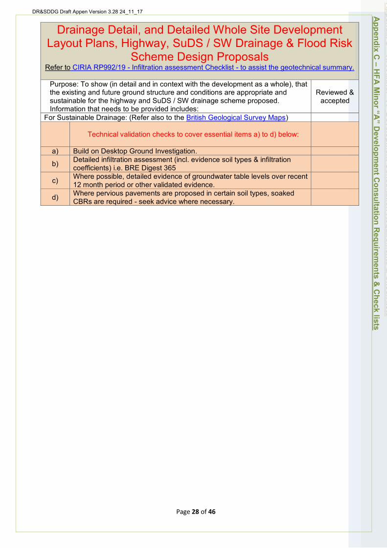
DR&SDDG Draft Appen Version 3.28 24_11_17
Drainage Detail, and Detailed Whole Site Development Layout Plans, Highway, SuDS / SW Drainage & Flood Risk
Scheme Design Proposals Refer to CIRIA RP992/19 - Infiltration assessment Checklist - to assist the geotechnical summary.
Purpose: To show (in detail and in context with the development as a whole), that the existing and future ground structure and conditions are appropriate and sustainable for the highway and SuDS / SW drainage scheme proposed. Information that needs to be provided includes:
Reviewed & accepted
For Sustainable Drainage: (Refer also to the British Geological Survey Maps)
Technical validation checks to cover essential items a) to d) below:
a) Build on Desktop Ground Investigation.
b) Detailed infiltration assessment (incl. evidence soil types & infiltration coefficients) i.e. BRE Digest 365
c) Where possible, detailed evidence of groundwater table levels over recent 12 month period or other validated evidence.
d) Where pervious pavements are proposed in certain soil types, soaked CBRs are required - seek advice where necessary.
Appendix C
– HFA
Minor “A
” Developm
ent Consultation R
equirements &
Check lists
Page 28 of 46
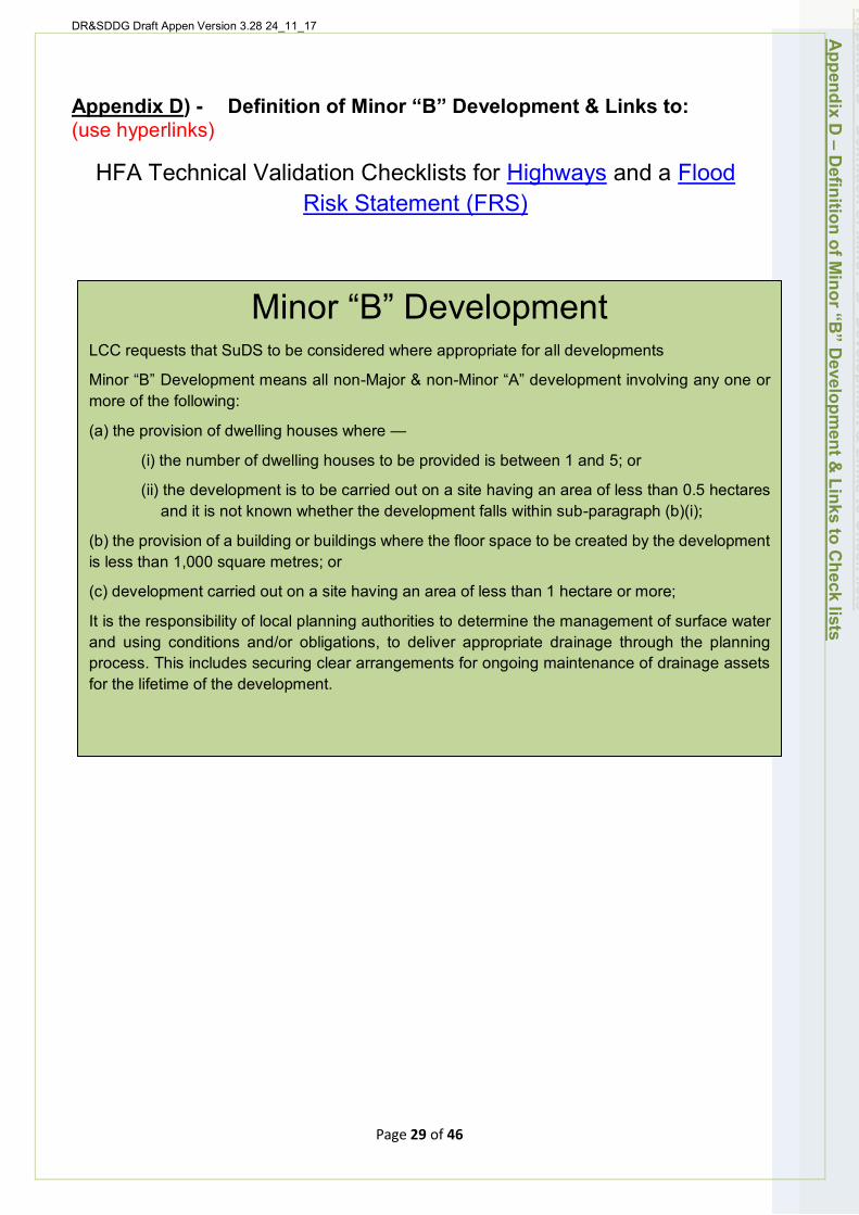
DR&SDDG Draft Appen Version 3.28 24_11_17
Appendix D) - Definition of Minor “B” Development & Links to: (use hyperlinks)
HFA Technical Validation Checklists for Highways and a Flood Risk Statement (FRS)
Minor “B” Development LCC requests that SuDS to be considered where appropriate for all developments
Minor “B” Development means all non-Major & non-Minor “A” development involving any one or more of the following:
(a) the provision of dwelling houses where —
(i) the number of dwelling houses to be provided is between 1 and 5; or
(ii) the development is to be carried out on a site having an area of less than 0.5 hectares and it is not known whether the development falls within sub-paragraph (b)(i);
(b) the provision of a building or buildings where the floor space to be created by the development is less than 1,000 square metres; or
(c) development carried out on a site having an area of less than 1 hectare or more;
It is the responsibility of local planning authorities to determine the management of surface water and using conditions and/or obligations, to deliver appropriate drainage through the planning process. This includes securing clear arrangements for ongoing maintenance of drainage assets for the lifetime of the development.
Appendix D
– Definition of M
inor “B” D
evelopment &
Links to Check lists
Page 29 of 46
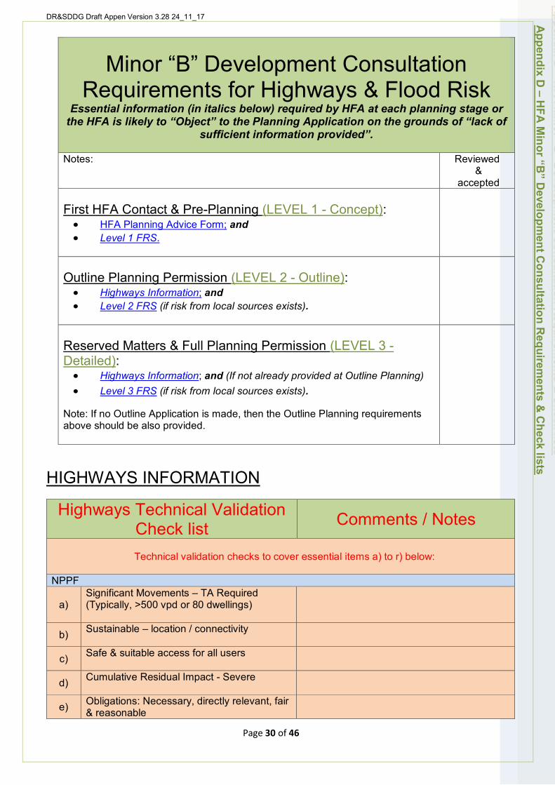
DR&SDDG Draft Appen Version 3.28 24_11_17 A
ppendix D – H
FA M
inor “B” D
evelopment C
onsultation Requirem
ents & C
heck lists
Minor “B” Development Consultation Requirements for Highways & Flood Risk
Essential information (in italics below) required by HFA at each planning stage or the HFA is likely to “Object” to the Planning Application on the grounds of “lack of
sufficient information provided”.
Notes: Reviewed &
accepted
First HFA Contact & Pre-Planning (LEVEL 1 - Concept): • HFA Planning Advice Form; and • Level 1 FRS.
Outline Planning Permission (LEVEL 2 - Outline): • Highways Information; and • Level 2 FRS (if risk from local sources exists).
Reserved Matters & Full Planning Permission (LEVEL 3 -Detailed): • Highways Information; and (If not already provided at Outline Planning) • Level 3 FRS (if risk from local sources exists).
Note: If no Outline Application is made, then the Outline Planning requirements above should be also provided.
HIGHWAYS INFORMATION
Page 30 of 46
Highways Technical Validation Check list Comments / Notes
Technical validation checks to cover essential items a) to r) below:
NPPF
a) Significant Movements – TA Required (Typically, >500 vpd or 80 dwellings)
b) Sustainable – location / connectivity
c) Safe & suitable access for all users
d) Cumulative Residual Impact - Severe
e) Obligations: Necessary, directly relevant, fair & reasonable
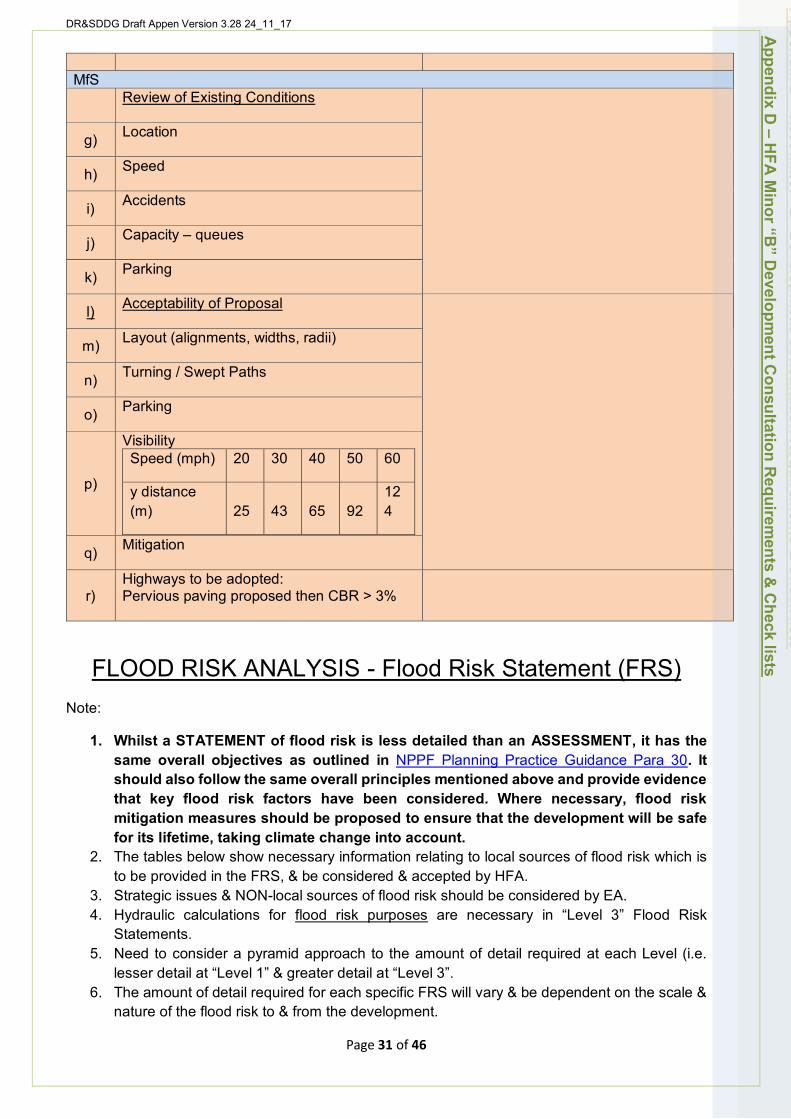
MfS
DR&SDDG Draft Appen Version 3.28 24_11_17
f) Review of Existing Conditions
g) Location
h) Speed
i) Accidents
j) Capacity – queues
k) Parking
l) Acceptability of Proposal
m) Layout (alignments, widths, radii)
n) Turning / Swept Paths
o) Parking
p)
Visibility Speed (mph) 20 30 40 50 60
y distance (m) 25 43 65 92
12 4
q) Mitigation
r) Highways to be adopted: Pervious paving proposed then CBR > 3%
Appendix D
– HFA
Minor “B
” Developm
ent Consultation R
equirements &
Check lists
FLOOD RISK ANALYSIS - Flood Risk Statement (FRS) Note:
1. Whilst a STATEMENT of flood risk is less detailed than an ASSESSMENT, it has the same overall objectives as outlined in NPPF Planning Practice Guidance Para 30. It should also follow the same overall principles mentioned above and provide evidence that key flood risk factors have been considered. Where necessary, flood risk mitigation measures should be proposed to ensure that the development will be safe for its lifetime, taking climate change into account.
2. The tables below show necessary information relating to local sources of flood risk which is to be provided in the FRS, & be considered & accepted by HFA.
3. Strategic issues & NON-local sources of flood risk should be considered by EA. 4. Hydraulic calculations for flood risk purposes are necessary in “Level 3” Flood Risk
Statements. 5. Need to consider a pyramid approach to the amount of detail required at each Level (i.e.
lesser detail at “Level 1” & greater detail at “Level 3”. 6. The amount of detail required for each specific FRS will vary & be dependent on the scale &
nature of the flood risk to & from the development.
Page 31 of 46
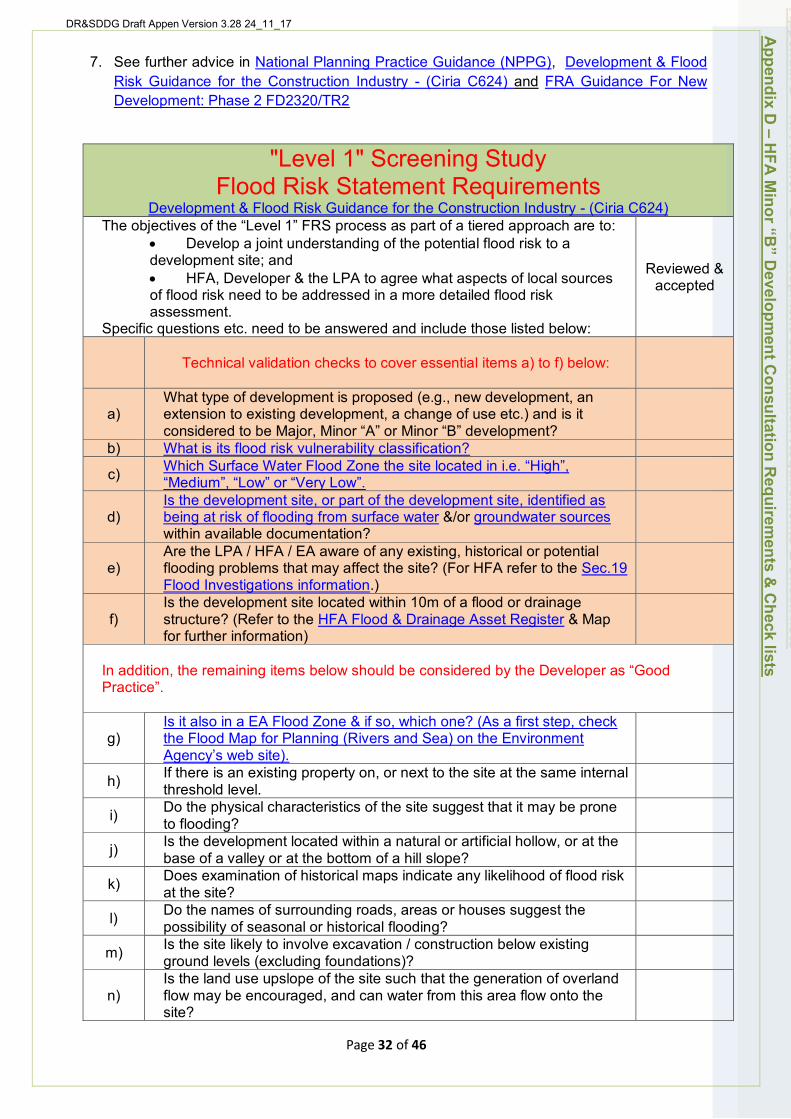
DR&SDDG Draft Appen Version 3.28 24_11_17
7. See further advice in National Planning Practice Guidance (NPPG), Development & Flood Risk Guidance for the Construction Industry - (Ciria C624) and FRA Guidance For New Development: Phase 2 FD2320/TR2
"Level 1" Screening Study Flood Risk Statement Requirements
Development & Flood Risk Guidance for the Construction Industry - (Ciria C624) The objectives of the “Level 1” FRS process as part of a tiered approach are to:
• Develop a joint understanding of the potential flood risk to a development site; and • HFA, Developer & the LPA to agree what aspects of local sources of flood risk need to be addressed in a more detailed flood risk assessment.
Specific questions etc. need to be answered and include those listed below:
Reviewed & accepted
Technical validation checks to cover essential items a) to f) below:
a)
b)
What type of development is proposed (e.g., new development, an extension to existing development, a change of use etc.) and is it considered to be Major, Minor “A” or Minor “B” development? What is its flood risk vulnerability classification?
c) Which Surface Water Flood Zone the site located in i.e. “High”, “Medium”, “Low” or “Very Low”.
d) Is the development site, or part of the development site, identified as being at risk of flooding from surface water &/or groundwater sources within available documentation?
e) Are the LPA / HFA / EA aware of any existing, historical or potential flooding problems that may affect the site? (For HFA refer to the Sec.19 Flood Investigations information.)
f) Is the development site located within 10m of a flood or drainage structure? (Refer to the HFA Flood & Drainage Asset Register & Map for further information)
In addition, the remaining items below should be considered by the Developer as “Good Practice”.
g) Is it also in a EA Flood Zone & if so, which one? (As a first step, check the Flood Map for Planning (Rivers and Sea) on the Environment Agency’s web site).
h) If there is an existing property on, or next to the site at the same internal threshold level.
i) Do the physical characteristics of the site suggest that it may be prone to flooding?
j) Is the development located within a natural or artificial hollow, or at the base of a valley or at the bottom of a hill slope?
k) Does examination of historical maps indicate any likelihood of flood risk at the site?
l) Do the names of surrounding roads, areas or houses suggest the possibility of seasonal or historical flooding?
m) Is the site likely to involve excavation / construction below existing ground levels (excluding foundations)?
n) Is the land use upslope of the site such that the generation of overland flow may be encouraged, and can water from this area flow onto the site?
Appendix D
– HFA
Minor “B
” Developm
ent Consultation R
equirements &
Check lists
Page 32 of 46
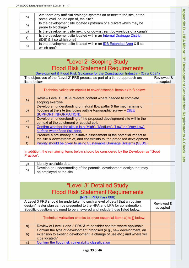
DR&SDDG Draft Appen Version 3.28 24_11_17
o)
p)
q)
r)
s)
Are there any artificial drainage systems on or next to the site, at the same level, or upslope of, the site? Is the development site located upstream of a culvert which may be prone to blockage? Is the development site next to or downstream/down-slope of a canal? Is the development site located within an Internal Drainage District (IDB) & if so which one? Is the development site located within an IDB Extended Area & if so which one?
"Level 2" Scoping Study Flood Risk Statement Requirements
Development & Flood Risk Guidance for the Construction Industry - (Ciria C624) The objectives of the “Level 2” FRS process as part of a tiered approach are listed below:
Reviewed & accepted
Technical validation checks to cover essential items a) to f) below:
a) Review Level 1 FRS & re-state content where needed to complete scoping exercise.
b) Develop an understanding of natural flow paths & the mechanisms of flooding at the site (including outline topographic survey – (SEE SUPPORT INFORMATION).
c) Develop an understanding of the proposed development site within the context of the catchment or coastal cell.
d) Confirm whether the site is in a “High”, “Medium”, “Low” or “Very Low” surface water flood risk zone.
e)
f)
Produce a preliminary qualitative assessment of the potential impact to
In addition, the remaining items below should be considered by the Developer as “Good
the site & downstream of, and constraints to, the proposed development. Priority should be given to using Sustainable Drainage Systems (SuDS).
Practice”.
g) Identify available data.
h) Develop an understanding of the potential development design that may be employed at the site.
Appendix D
– HFA
Minor “B
” Developm
ent Consultation R
equirements &
Check lists
"Level 3" Detailed Study Flood Risk Statement Requirements
(NPPF PPG Para 068) A Level 3 FRS should be undertaken to such a level of detail that an outline design/master plan can be presented to the HFA and LPA for consideration. Specific questions etc need to be answered and include those listed below:
Reviewed & accepted
a)
Technical validation checks to cover essential items a) to j) below:
Review of Level 1 and 2 FRS & re-consider content where applicable.
b)
c)
Confirm the type of development proposed (e.g., new development, an extension to existing development, a change of use etc.) and where will it be located? Confirm the flood risk vulnerability classification
Page 33 of 46
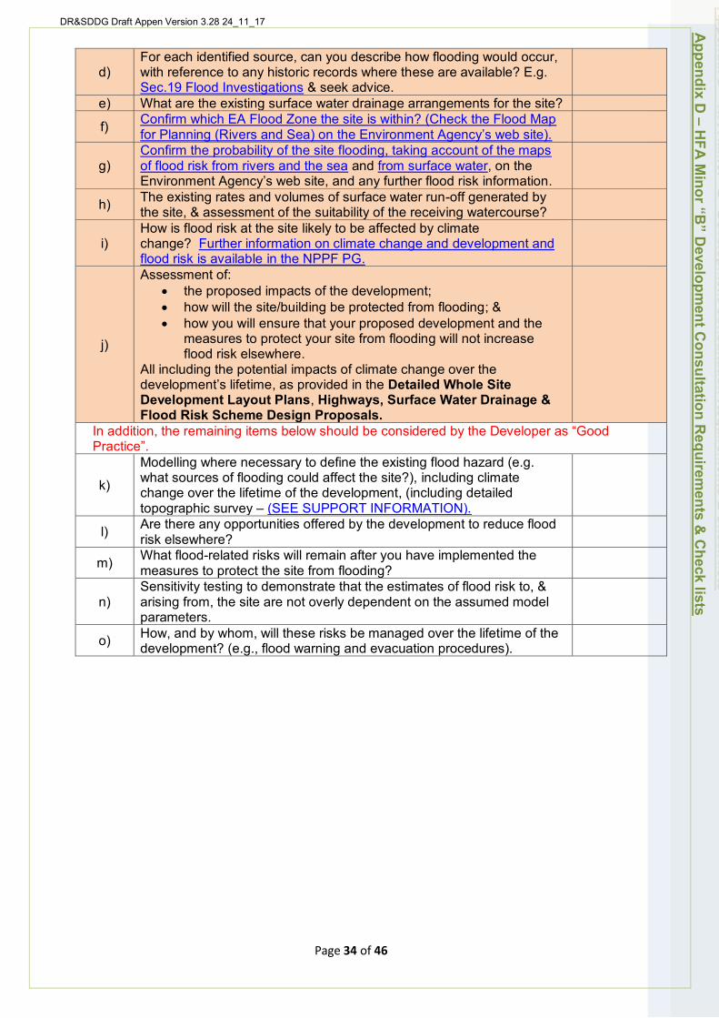
DR&SDDG Draft Appen Version 3.28 24_11_17
For each identified source, can you describe how flooding would occur, d) with reference to any historic records where these are available? E.g.
Sec.19 Flood Investigations & seek advice. e) What are the existing surface water drainage arrangements for the site?
Confirm which EA Flood Zone the site is within? (Check the Flood Map f) for Planning (Rivers and Sea) on the Environment Agency’s web site). Confirm the probability of the site flooding, taking account of the maps
g) of flood risk from rivers and the sea and from surface water, on the Environment Agency’s web site, and any further flood risk information. The existing rates and volumes of surface water run-off generated by h) the site, & assessment of the suitability of the receiving watercourse? How is flood risk at the site likely to be affected by climate
i) change? Further information on climate change and development and flood risk is available in the NPPF PG. Assessment of:
• the proposed impacts of the development; • how will the site/building be protected from flooding; & • how you will ensure that your proposed development and the
measures to protect your site from flooding will not increase j) flood risk elsewhere.
All including the potential impacts of climate change over the development’s lifetime, as provided in the Detailed Whole Site Development Layout Plans, Highways, Surface Water Drainage & Flood Risk Scheme Design Proposals.
In addition, the remaining items below should be considered by the Developer as “Good Practice”.
Modelling where necessary to define the existing flood hazard (e.g. what sources of flooding could affect the site?), including climate k) change over the lifetime of the development, (including detailed topographic survey – (SEE SUPPORT INFORMATION). Are there any opportunities offered by the development to reduce flood l) risk elsewhere? What flood-related risks will remain after you have implemented the m) measures to protect the site from flooding? Sensitivity testing to demonstrate that the estimates of flood risk to, &
n) arising from, the site are not overly dependent on the assumed model parameters. How, and by whom, will these risks be managed over the lifetime of the o) development? (e.g., flood warning and evacuation procedures).
Appendix D
– HFA
Minor “B
” Developm
ent Consultation R
equirements &
Check lists
Page 34 of 46

DR&SDDG Draft Appen Version 3.28 24_11_17
Appendix E) - Further HFA Consultation Support Information & Links to:
DM Technical Validation Check lists SUPPORT information for Major, Minor “A” & Minor “B” development types as necessary:
(use hyperlinks)
• Topographic Survey; • Whole Site Drainage; • Surface Water Discharge Agreement; • SuDS Scheme Maintenance; • Water Quality Treatment; • Landscape; • Construction Management; • Construction Method Statement; and • Construction Phasing.
Appendix E
– Further HFA
Consultation Support Inform
ation & C
heck lists
Page 35 of 46
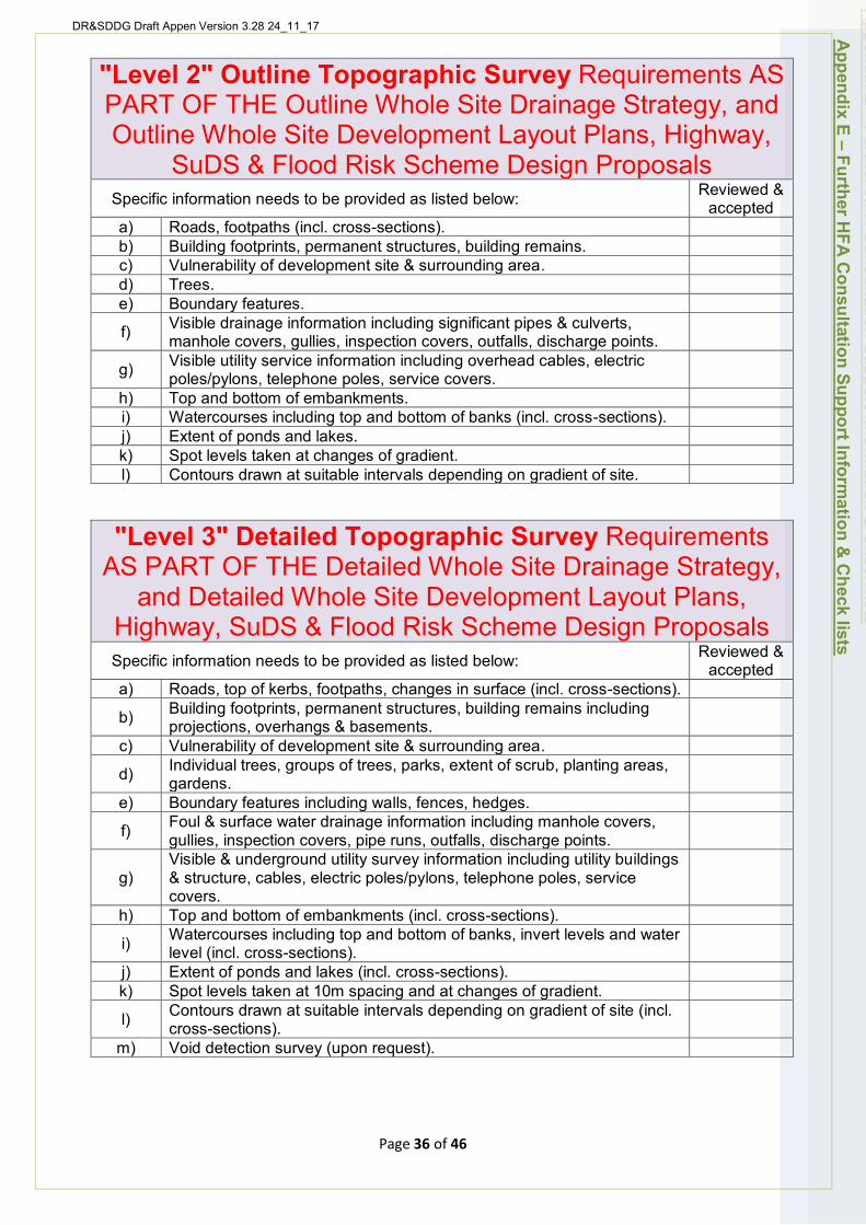
DR&SDDG Draft Appen Version 3.28 24_11_17
"Level 2" Outline Topographic Survey Requirements AS PART OF THE Outline Whole Site Drainage Strategy, and Outline Whole Site Development Layout Plans, Highway,
SuDS & Flood Risk Scheme Design Proposals Specific information needs to be provided as listed below: Reviewed &
accepted a) Roads, footpaths (incl. cross-sections). b) Building footprints, permanent structures, building remains. c) Vulnerability of development site & surrounding area. d) Trees. e) Boundary features.
f) Visible drainage information including significant pipes & culverts, manhole covers, gullies, inspection covers, outfalls, discharge points.
g) Visible utility service information including overhead cables, electric poles/pylons, telephone poles, service covers.
h) Top and bottom of embankments. i) Watercourses including top and bottom of banks (incl. cross-sections). j) Extent of ponds and lakes. k) Spot levels taken at changes of gradient. l) Contours drawn at suitable intervals depending on gradient of site.
"Level 3" Detailed Topographic Survey Requirements AS PART OF THE Detailed Whole Site Drainage Strategy,
and Detailed Whole Site Development Layout Plans, Highway, SuDS & Flood Risk Scheme Design Proposals Specific information needs to be provided as listed below: Reviewed &
accepted a) Roads, top of kerbs, footpaths, changes in surface (incl. cross-sections).
b) Building footprints, permanent structures, building remains including projections, overhangs & basements.
c) Vulnerability of development site & surrounding area.
d) Individual trees, groups of trees, parks, extent of scrub, planting areas, gardens.
e) Boundary features including walls, fences, hedges.
f) Foul & surface water drainage information including manhole covers, gullies, inspection covers, pipe runs, outfalls, discharge points.
g) Visible & underground utility survey information including utility buildings & structure, cables, electric poles/pylons, telephone poles, service covers.
h) Top and bottom of embankments (incl. cross-sections).
i) Watercourses including top and bottom of banks, invert levels and water level (incl. cross-sections).
j) Extent of ponds and lakes (incl. cross-sections). k) Spot levels taken at 10m spacing and at changes of gradient.
l) Contours drawn at suitable intervals depending on gradient of site (incl. cross-sections).
m) Void detection survey (upon request).
Appendix E
– Further HFA
Consultation Support Inform
ation & C
heck lists
Page 36 of 46
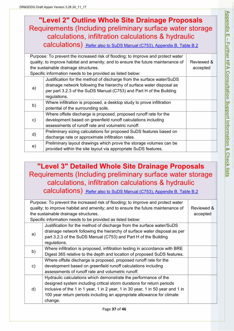
DR&SDDG Draft Appen Version 3.28 24_11_17 Appendix E
– Further HFA
Consultation Support Inform
ation & C
heck lists
"Level 2" Outline Whole Site Drainage Proposals Requirements (Including preliminary surface water storage
calculations, infiltration calculations & hydraulic calculations) Refer also to SuDS Manual (C753), Appendix B, Table B.2
Purpose: To prevent the increased risk of flooding; to improve and protect water quality; to improve habitat and amenity; and to ensure the future maintenance of Reviewed & the sustainable drainage structures. accepted Specific information needs to be provided as listed below:
Justification for the method of discharge from the surface water/SuDS
a) drainage network following the hierarchy of surface water disposal as per part 3.2.3 of the SuDS Manual (C753) and Part H of the Building regulations.
b) Where infiltration is proposed, a desktop study to prove infiltration potential of the surrounding soils. Where offsite discharge is proposed, proposed runoff rate for the
c) development based on greenfield runoff calculations including assessments of runoff rate and volumetric runoff.
d) Preliminary sizing calculations for proposed SuDS features based on discharge rate or approximate infiltration rates.
e) Preliminary layout drawings which prove the storage volumes can be provided within the site layout via appropriate SuDS features.
"Level 3" Detailed Whole Site Drainage Proposals Requirements (Including preliminary surface water storage
calculations, infiltration calculations & hydraulic calculations) Refer also to SuDS Manual (C753), Appendix B, Table B.2
Purpose: To prevent the increased risk of flooding; to improve and protect water quality; to improve habitat and amenity; and to ensure the future maintenance of Reviewed & the sustainable drainage structures. accepted Specific information needs to be provided as listed below:
Justification for the method of discharge from the surface water/SuDS drainage network following the hierarchy of surface water disposal as per a) part 3.2.3 of the SuDS Manual (C753) and Part H of the Building regulations. Where infiltration is proposed, infiltration testing in accordance with BRE
b) Digest 365 relative to the depth and location of proposed SuDS features. Where offsite discharge is proposed, proposed runoff rate for the
c) development based on greenfield runoff calculations including assessments of runoff rate and volumetric runoff. Hydraulic calculations which demonstrate the performance of the designed system including critical storm durations for return periods
d) inclusive of the 1 in 1 year, 1 in 2 year, 1 in 30 year, 1 in 50 year and 1 in 100 year return periods including an appropriate allowance for climate change.
Page 37 of 46
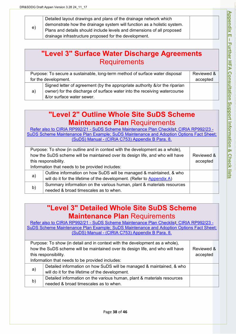
DR&SDDG Draft Appen Version 3.28 24_11_17
Detailed layout drawings and plans of the drainage network which demonstrate how the drainage system will function as a holistic system.
e) Plans and details should include levels and dimensions of all proposed drainage infrastructure proposed for the development.
"Level 3" Surface Water Discharge Agreements Requirements
Purpose: To secure a sustainable, long-term method of surface water disposal for the development.
Reviewed & accepted
a) Signed letter of agreement (by the appropriate authority &/or the riparian owner) for the discharge of surface water into the receiving watercourse &/or surface water sewer.
"Level 2" Outline Whole Site SuDS Scheme Maintenance Plan Requirements
Refer also to CIRIA RP992/21 - SuDS Scheme Maintenance Plan Checklist; CIRIA RP992/23 -SuDS Scheme Maintenance Plan Example; SuDS Maintenance and Adoption Options Fact Sheet;
(SuDS) Manual - (CIRIA C753) Appendix B Para. 8.
Purpose: To show (in outline and in context with the development as a whole), how the SuDS scheme will be maintained over its design life, and who will have this responsibility. Information that needs to be provided includes:
Reviewed & accepted
a) Outline information on how SuDS will be managed & maintained, & who will do it for the lifetime of the development. (Refer to Appendix A)
b) Summary information on the various human, plant & materials resources needed & broad timescales as to when.
"Level 3" Detailed Whole Site SuDS Scheme Maintenance Plan Requirements
Refer also to CIRIA RP992/21 - SuDS Scheme Maintenance Plan Checklist; CIRIA RP992/23 -SuDS Scheme Maintenance Plan Example; SuDS Maintenance and Adoption Options Fact Sheet;
(SuDS) Manual - (CIRIA C753) Appendix B Para. 8.
Purpose: To show (in detail and in context with the development as a whole), how the SuDS scheme will be maintained over its design life, and who will have this responsibility. Information that needs to be provided includes:
Reviewed & accepted
a) Detailed information on how SuDS will be managed & maintained, & who will do it for the lifetime of the development.
b) Detailed information on the various human, plant & materials resources needed & broad timescales as to when.
Appendix E
– Further HFA
Consultation Support Inform
ation & C
heck lists
Page 38 of 46
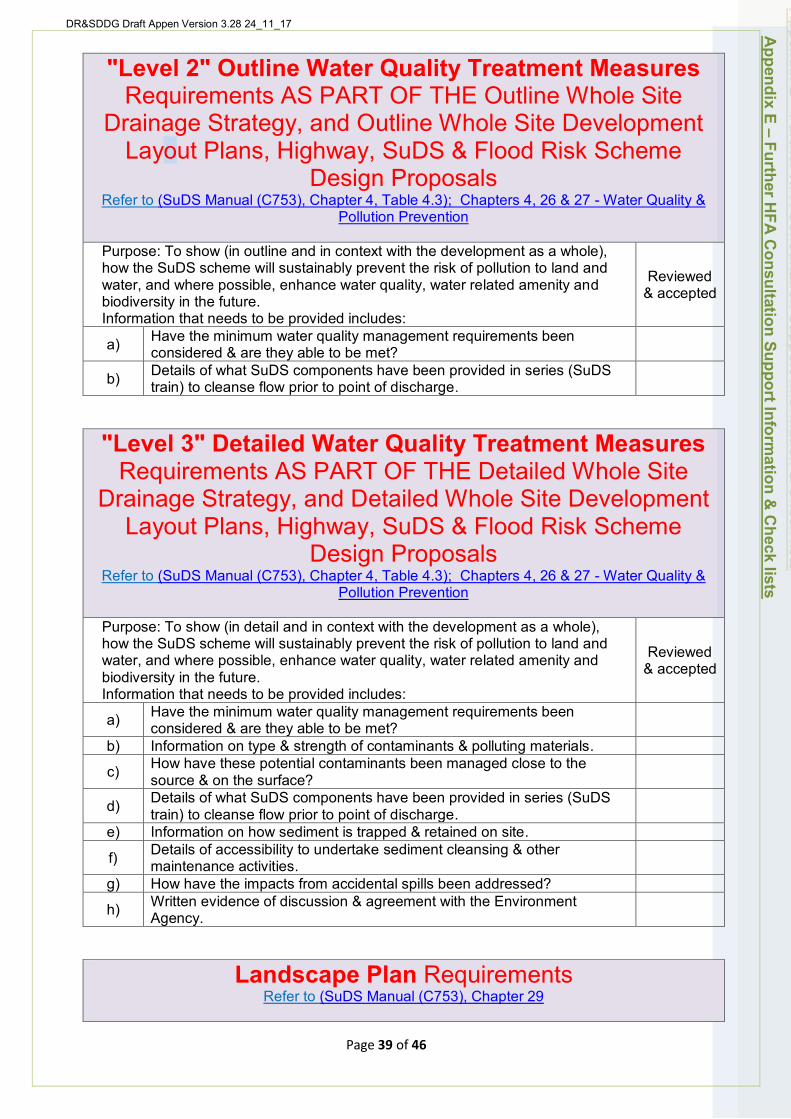
DR&SDDG Draft Appen Version 3.28 24_11_17
"Level 2" Outline Water Quality Treatment Measures Requirements AS PART OF THE Outline Whole Site
Drainage Strategy, and Outline Whole Site Development Layout Plans, Highway, SuDS & Flood Risk Scheme
Design Proposals Refer to (SuDS Manual (C753), Chapter 4, Table 4.3); Chapters 4, 26 & 27 - Water Quality &
Pollution Prevention
Purpose: To show (in outline and in context with the development as a whole), how the SuDS scheme will sustainably prevent the risk of pollution to land and water, and where possible, enhance water quality, water related amenity and biodiversity in the future. Information that needs to be provided includes:
Have the minimum water quality management requirements been a) considered & are they able to be met? Details of what SuDS components have been provided in series (SuDS b) train) to cleanse flow prior to point of discharge.
"Level 3" Detailed Water Quality Treatment Measures Requirements AS PART OF THE Detailed Whole Site
Reviewed & accepted
Drainage Strategy, and Detailed Whole Site Development Layout Plans, Highway, SuDS & Flood Risk Scheme
Design Proposals Refer to (SuDS Manual (C753), Chapter 4, Table 4.3); Chapters 4, 26 & 27 - Water Quality &
Pollution Prevention
Purpose: To show (in detail and in context with the development as a whole), how the SuDS scheme will sustainably prevent the risk of pollution to land and water, and where possible, enhance water quality, water related amenity and biodiversity in the future. Information that needs to be provided includes:
Have the minimum water quality management requirements been a) considered & are they able to be met? b) Information on type & strength of contaminants & polluting materials.
How have these potential contaminants been managed close to the c) source & on the surface? Details of what SuDS components have been provided in series (SuDS d) train) to cleanse flow prior to point of discharge.
e) Information on how sediment is trapped & retained on site. Details of accessibility to undertake sediment cleansing & other f) maintenance activities.
g) How have the impacts from accidental spills been addressed? Written evidence of discussion & agreement with the Environment h) Agency.
Landscape Plan Requirements Refer to (SuDS Manual (C753), Chapter 29
Reviewed & accepted
Appendix E
– Further HFA
Consultation Support Inform
ation & C
heck lists
Page 39 of 46

DR&SDDG Draft Appen Version 3.28 24_11_17
The objectives of the landscape plan are to: • Design for effective attenuation, flow control and exceedance; • Improve water quality; • Design an attractive feature in the local landscape; • Improve ecological function and biodiversity; • Use land efficiently and enhance land values; and • Assess risk and reflect the response within the design.
Specific information that needs to be submitted includes:
Reviewed & accepted
a) Detailed overall layout, ground contouring, planting, hard, soft & water features.
b) Detail landscape elements to improve water quality.
c) Show how the design achieves effective attenuation, flow control & exceedance.
d) Improvements to ecology & biodiversity.
e) Detailed consideration of effective routine & periodic maintenance activities.
f) Full understanding of the sites character: slope, gradient, ground modelling, geology, soils types, natural drainage patterns.
g) Show existing features to be preserved, enhanced, removed &/or replaced.
h) Details of any soils stabilization/reinforcement & erosion control.
Construction Management Plan Requirements SuDS Manual (C753), Chapter 29 – Landscape Plans & Chapter 31 - Construction
Purpose of the Construction Management Plan: To ensure the developer and their contractors have taken reasonable steps to ensure risks from flooding and pollution are appropriately managed and mitigated during the construction phase of the development. Specific information that needs to be submitted includes:
Reviewed & accepted
a) Strategy stating how surface water runoff on and from the will be managed during the construction.
b) Details of temporary pollution control measures.
c) Details of how permanent SuDs features will be protected during construction.
d) Drawing showing the sequencing of the construction activities
Construction Method Statement Requirements Refer to SuDS Manual (C753), Appendix B, - Section B.6 -Construction Method Statements &
Assessment Checklists
Purpose of the Construction Method Statement: To ensure the developer and their contractors have taken reasonable steps to ensure risks from flooding and pollution are appropriately managed and mitigated during the construction phase of the development. Specific information that needs to be submitted includes:
Reviewed & accepted
a) Details of the nature of the work to be completed.
b) Site plans & full scheme drawings, where required to support the method of approach.
c) Consents & reinstatement requirements.
Appendix E
– Further HFA
Consultation Support Inform
ation & C
heck lists
Page 40 of 46

DR&SDDG Draft Appen Version 3.28 24_11_17
d) Access points & details.
e) Any site-specific ecological issues, or features that require protection &/or consideration.
f) Pollution control arrangements & any likely water quality issues resulting from the highways & SuDS construction.
g)
The proposed strategy for sediment control, erosion control & site drainage during the construction of the development, where this impacts on the SuDS proposed for the site, it should identify any potential impacts on the final performance of the drainage system & any necessary protection measures (or remedial works) such as silt removal at the end of construction of the development.
h)
Measures to prevent the inadvertent access across the completed or partially completed SuDS; for example, the area above a geo-cellular tank that has not been designed to support heavy traffic, or a completed infiltration basin that cannot be trafficked, should be surrounded by a physical barrier, vehicle access routes should be clearly marked.
Construction Phasing Plan Requirements Purpose of the Construction Phasing Plan: To ensure the developer and their contractors have taken reasonable steps to ensure risks from flooding and pollution are appropriately managed and mitigated during the construction phase of the development. Specific information that needs to be submitted includes:
Reviewed & accepted
a) Strategy clearly stating how the development and/or phase of the development will drain during the construction and occupation of the development prior to adoption.
b)
Drawing(s) showing the sequencing of phases of the development and how the drainage systems (permanent or temporary) connect to an outfall (temporary or permanent) during the construction and occupation of the development prior to adoption.
Appendix E
– Further HFA
Consultation Support Inform
ation & C
heck lists
Page 41 of 46
DR&SDDG Draft Appen Version 3.28 24_11_17
Appendix F) - First Contact with HFA Planning Advice Service Form
First Contact with HFA Planning Advice Form and Request for a Meeting
Before requesting local authority, pre-planning advice or submitting a planning application to a Local Planning Authority in Lincolnshire, you are advised to discuss your proposal with us (free of charge), to find out whether the initial principles of your proposal are acceptable or not to the HFA.
Our advice will be based on the information you provide on this form and any additional supporting material provided. Therefore, the more information you can give about the proposal, the more informal advice on highways, flood risk and drainage we can provide. The checklist below identifies the basic information that is needed when we meet, in order that we can advise you appropriately.
We cannot provide informal advice that is binding on the HFA. Any views or opinions will be given in good faith without prejudice to the formal planning application process which will be subject to public consultation. This service does not guarantee that any subsequent applications will be valid or that they will be approved. This "First Contact with HFA - Planning Advice Service" aims to help identify issues that may be raised should a planning application be submitted so that they can be properly considered prior to an application being made.
If you have any queries or require further information on completing this form please e-mail the Highways & Flood Risk Development Team at floodwater&[email protected] or telephone 01522 782070.
Person andOrganisationEnquiring
Appendix F – First C
ontact with H
FA – Planning A
dvice Service Form
Page 42 of 46

DR&SDDG Draft Appen Version 3.28 24_11_17
Name:
Organisation:
Address:
Postcode: Telephone:
E-mail address:
Agent (if applicable)
Name:
Organisation:
Address:
Postcode: Telephone:
E-mail address:
Please return this form by e-mail to floodwater&[email protected] or by post to The County Manager for Development (Highways & Flood Risk), Lincolnshire County Council Environment and Economy Directorate, Lancaster House, 36 Orchard Street, LINCOLN. LN1 1XX. A member of the Highways & Flood Risk Development Management Team will contact you to arrange a suitable time and date to hold a meeting with the HFA at Witham Park House as soon as possible.
General Description of Proposed Development
Location of Application Site
Appendix F – First C
ontact with H
FA – Planning A
dvice Service Form
Fulladdress ofapplication site:
Page 43 of 46
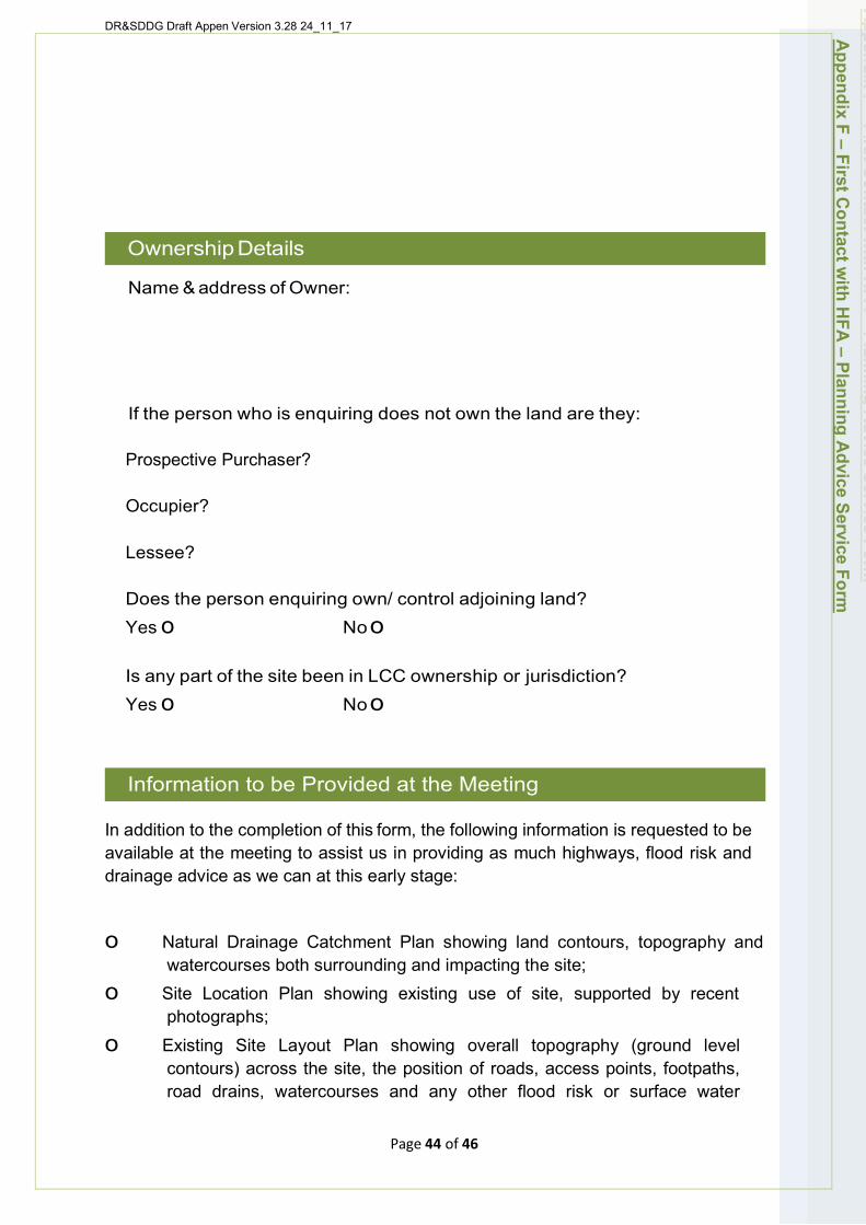
DR&SDDG Draft Appen Version 3.28 24_11_17
Ownership Details
Name & address of Owner:
If the person who is enquiring does not own the land are they:
Prospective Purchaser?
Occupier?
Lessee?
Does the person enquiring own/ control adjoining land? Yes o Noo
Is any part of the site been in LCC ownership or jurisdiction? Yes o Noo
Information to be Provided at the Meeting
In addition to the completion of this form, the following information is requested to be available at the meeting to assist us in providing as much highways, flood risk and drainage advice as we can at this early stage:
o Natural Drainage Catchment Plan showing land contours, topography and watercourses both surrounding and impacting the site;
o Site Location Plan showing existing use of site, supported by recent photographs;
o Existing Site Layout Plan showing overall topography (ground level contours) across the site, the position of roads, access points, footpaths, road drains, watercourses and any other flood risk or surface water
Appendix F – First C
ontact with H
FA – Planning A
dvice Service Form
Page 44 of 46
DR&SDDG Draft Appen Version 3.28 24_11_17
drainage features that need to be taken into account; and o Rough sketches or concept drawings (if available), of the proposed
development layout (or layout options), showing the location of roads and sustainable drainage features, plus any potential flood risk protection features that may be required.
Disclaimer Any advice given by officers as part of this "First Contact with HFA - Planning Advice Service" does not indicate any formal decision by the HFA. Any views or opinions are given without prejudice to the formal consideration of any planning or other application. The final decision on any planning application that you may then make, can only be taken after the Local Planning Authority has consulted local people, statutory consultees (including the HFA), and any other interested parties and will then be made either by the Local Planning Committee, or under delegated powers in accordance with the Local Authority Approved Scheme of Delegation, based on all of the information available at that time. Officers cannot therefore guarantee the final formal decision that will be made on your planning application(s).
Freedom of Information You are also advised that your request in respect of this "First Contact with HFA -Planning Advice Service" may be required to be disclosed should there be a request under the Freedom of Information Act and as such this HFA is not able to ensure your enquiry is confidential.
Declaration
I the undersigned, confirm that I am seeking the "First Contact with HFA Planning Advice Service" with regard to the proposed development described on this form at the location identified. I also confirm that I'm aware that the HFA is not able to ensure my enquiry is confidential.
Signed: On behalf of:
Date:
Appendix F – First C
ontact with H
FA – Planning A
dvice Service Form
Page 45 of 46
DR&SDDG Draft Appen Version 3.28 24_11_17
Appendix G) - Useful Guidance Documents (use hyperlinks)
1) Manual for Streets
2) All Local Transport Notes
3) SuDS Maintenance & Adoptions Options (England) Factsheet - Susdrain
4) Planning for SuDS - Making it Happen CIRIA C687
5) Site Handbook for the Construction of SuDS - CIRIA C698
6) English Non-Statutory Technical Standards for Sustainable Drainage - DEFRA 2015
7) Non-Statutory Technical Standards for Sustainable Drainage: Practice Guidance - LASOO 2015
8) Anglian Water SuDS Adoption Manual
9) Guidance on the Construction of SuDS 2017 (C768)
10) Local Transport Note 1-11 Shared Space
11) DMRB
12) Local Transport Note 1-12 shared-use-routes-for-pedestrians-and-cyclists.pdf
13) Transport Assessment Guidance 2007 (withdrawn)
14) Current Govt Guidance on Transport Assessments and Travel Plans
15) Govt Guidance on Parking Standards
16) Govt Guidance on Use of Planning Conditions
17) Home Zone Guidelines
Appendix G
– Useful G
uidance Docum
ents
Page 46 of 46