Embed Size (px)
DESCRIPTION
http://www.seipub.org/aime/paperInfo.aspx?ID=4103 Recent advances in space system design have led to increasingly complex spacecraft and mission objectives, and hence, both telemetry and visual data are important for monitoring such systems for space activities. The Interplanetary Kite-craft Accelerated by Radiation of the Sun (IKAROS) spacecraft was launched on May 21, 2010; with the mission to evaluate the performance of solar power sails which are large membranes that utilize sunlight for propulsion. The visual monitoring system for IKAROS must be small, low-cost, and intelligent. For this purpose, a very small, high-performance image processing unit (HP-IMAP) has been developed based on commercial off-the-shelf technologies. This unit has a calculation capability of 500 million instructions per second in a single 50 mm×50 mm printed circuit board, and incorporates various types of interfaces using field-programmable gate array technology. This visual monitoring system was la
Citation preview
Advances in Microelectronic Engineering (AIME) Volume 1 Issue 3, July 2013 www.seipub.org/aime
57
HighPerformance Visual Monitoring System For IKAROS Commercial-off-the-Shelf Approach for Space System Shinnichi Kimura*1, Masato Terakura*2, Hirotaka Sawada*3 *1-2 Department of Electrical Engineering, Tokyo University of Science, *3 Institute of Space and Astronautical Science, Japan Aerospace Exploration Agency *[email protected]; [email protected]; [email protected] Abstract
Recent advances in space system design have led to increasingly complex spacecraft and mission objectives, and hence, both telemetry and visual data are important for monitoring such systems for space activities. The Interplanetary Kite-craft Accelerated by Radiation of the Sun (IKAROS) spacecraft was launched on May 21, 2010; with the mission to evaluate the performance of solar power sails which are large membranes that utilize sunlight for propulsion. The visual monitoring system for IKAROS must be small, low-cost, and intelligent. For this purpose, a very small, high-performance image processing unit (HP-IMAP) has been developed based on commercial off-the-shelf technologies. This unit has a calculation capability of 500 million instructions per second in a single 50 mm×50 mm printed circuit board, and incorporates various types of interfaces using field-programmable gate array technology. This visual monitoring system was launched with IKAROS and has successfully supported IKAROS operations. Using HP-IMAP, we have successfully achieved the world’s first images taken by a spacecraft itself. In this paper, the outline of HP-IMAP for IKAROS has been depicted and the results obtained have been presented using this system on IKAROS.
Keywords
High-Performance Monitoring Camera, FPGA, Image Processing, Commercial-off-the-Shelf Technology, IKAROS
Introduction
Recently, there has been a growing need for the development of advanced visual monitoring of spacecrafts operated in space. With recent advances in space system design and increasingly complex spacecraft and mission objectives, both telemetry and visual data are important for monitoring such systems [1-4]. In addition, visual capabilities can be used for sensing (e.g., star sensors[5-7]), and such data obtained can be utilized for educational purposes. Small satellites, including some designed by universities, have become increasingly popular, and in such cases,
visual capabilities are considered to be important for educational purposes. Therefore, small, low-cost space cameras are required for various applications.
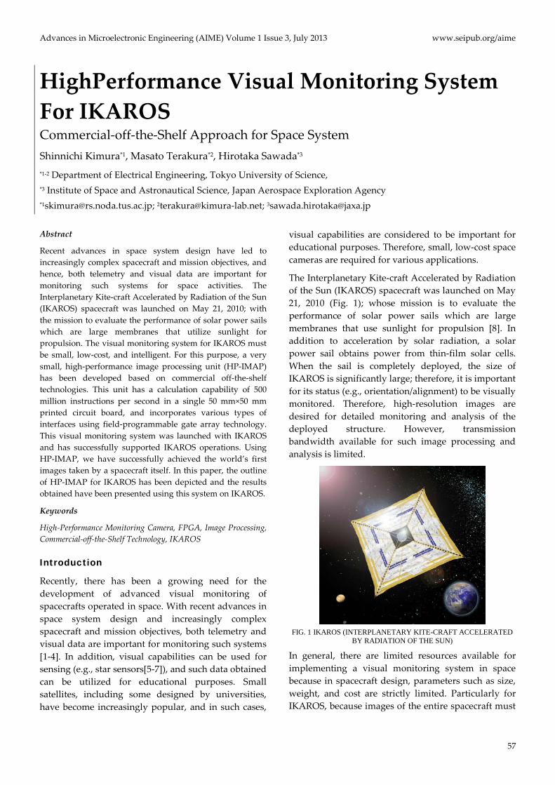
The Interplanetary Kite-craft Accelerated by Radiation of the Sun (IKAROS) spacecraft was launched on May 21, 2010 (Fig. 1); whose mission is to evaluate the performance of solar power sails which are large membranes that use sunlight for propulsion [8]. In addition to acceleration by solar radiation, a solar power sail obtains power from thin-film solar cells. When the sail is completely deployed, the size of IKAROS is significantly large; therefore, it is important for its status (e.g., orientation/alignment) to be visually monitored. Therefore, high-resolution images are desired for detailed monitoring and analysis of the deployed structure. However, transmission bandwidth available for such image processing and analysis is limited.
FIG. 1 IKAROS (INTERPLANETARY KITE-CRAFT ACCELERATED
BY RADIATION OF THE SUN)
In general, there are limited resources available for implementing a visual monitoring system in space because in spacecraft design, parameters such as size, weight, and cost are strictly limited. Particularly for IKAROS, because images of the entire spacecraft must
www.seipub.org/aime Advances in Microelectronic Engineering (AIME) Volume 1 Issue 3, July 2013
58
be acquired using a small camera that can be ejected from the spacecraft, the camera must be as small as possible. Moreover, a high-performance processor is required for the monitoring system to enable image processing and compression prior to downlink transmission, because the available communication bandwidth for IKAROS is very limited. Therefore, the visual monitoring system for IKAROS must be small, low-cost, and intelligent.
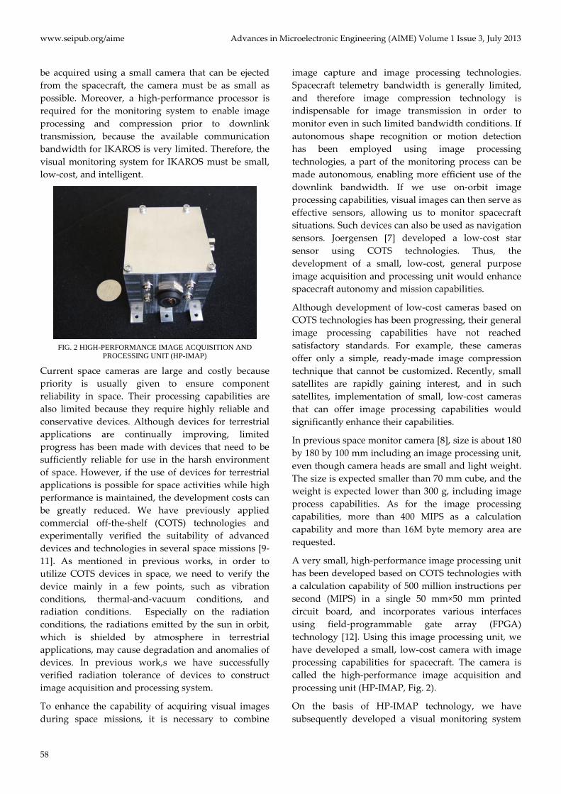
FIG. 2 HIGH-PERFORMANCE IMAGE ACQUISITION AND
PROCESSING UNIT (HP-IMAP)
Current space cameras are large and costly because priority is usually given to ensure component reliability in space. Their processing capabilities are also limited because they require highly reliable and conservative devices. Although devices for terrestrial applications are continually improving, limited progress has been made with devices that need to be sufficiently reliable for use in the harsh environment of space. However, if the use of devices for terrestrial applications is possible for space activities while high performance is maintained, the development costs can be greatly reduced. We have previously applied commercial off-the-shelf (COTS) technologies and experimentally verified the suitability of advanced devices and technologies in several space missions [9-11]. As mentioned in previous works, in order to utilize COTS devices in space, we need to verify the device mainly in a few points, such as vibration conditions, thermal-and-vacuum conditions, and radiation conditions. Especially on the radiation conditions, the radiations emitted by the sun in orbit, which is shielded by atmosphere in terrestrial applications, may cause degradation and anomalies of devices. In previous work,s we have successfully verified radiation tolerance of devices to construct image acquisition and processing system.
To enhance the capability of acquiring visual images during space missions, it is necessary to combine
image capture and image processing technologies. Spacecraft telemetry bandwidth is generally limited, and therefore image compression technology is indispensable for image transmission in order to monitor even in such limited bandwidth conditions. If autonomous shape recognition or motion detection has been employed using image processing technologies, a part of the monitoring process can be made autonomous, enabling more efficient use of the downlink bandwidth. If we use on-orbit image processing capabilities, visual images can then serve as effective sensors, allowing us to monitor spacecraft situations. Such devices can also be used as navigation sensors. Joergensen [7] developed a low-cost star sensor using COTS technologies. Thus, the development of a small, low-cost, general purpose image acquisition and processing unit would enhance spacecraft autonomy and mission capabilities.
Although development of low-cost cameras based on COTS technologies has been progressing, their general image processing capabilities have not reached satisfactory standards. For example, these cameras offer only a simple, ready-made image compression technique that cannot be customized. Recently, small satellites are rapidly gaining interest, and in such satellites, implementation of small, low-cost cameras that can offer image processing capabilities would significantly enhance their capabilities.
In previous space monitor camera [8], size is about 180 by 180 by 100 mm including an image processing unit, even though camera heads are small and light weight. The size is expected smaller than 70 mm cube, and the weight is expected lower than 300 g, including image process capabilities. As for the image processing capabilities, more than 400 MIPS as a calculation capability and more than 16M byte memory area are requested.
A very small, high-performance image processing unit has been developed based on COTS technologies with a calculation capability of 500 million instructions per second (MIPS) in a single 50 mm×50 mm printed circuit board, and incorporates various interfaces using field-programmable gate array (FPGA) technology [12]. Using this image processing unit, we have developed a small, low-cost camera with image processing capabilities for spacecraft. The camera is called the high-performance image acquisition and processing unit (HP-IMAP, Fig. 2).
On the basis of HP-IMAP technology, we have subsequently developed a visual monitoring system
Advances in Microelectronic Engineering (AIME) Volume 1 Issue 3, July 2013 www.seipub.org/aime
59
for IKAROS, called the “HP-IMAP for IKAROS”. This system acquires high-resolution 360 degree panoramic images of the deployed membrane using four high-resolution cameras known as CAM-H, as well as images of the entire spacecraft using two separatable cameras called DCAM. The HP-IMAP for IKAROS was launched on IKAROS and has successfully supported IKAROS operations. Using DCAM, we have obtained the world’s first spacecraft images taken by the spacecraft itself. The successful image acquisition by the DCAM indicates the effectiveness of the concept whereby images can be acquired by separate microprobes. It can be utilized for monitoring situations by the so-called Eyeball concept [3], and for acquiring information from some distance from the main satellite. The experiment also confirms the value of visual information to situation monitoring, experiment verification, outreach applications, and so on. In this paper, the HP-IMAP has been described for IKAROS and the results has been presented obtained by demonstrating this technology on IKAROS.
IKAROS
IKAROS is the world’s first solar power sail craft that uses both photon propulsion and thin-film solar power generation in the course of its interplanetary cruise (Fig. 1).
The membrane, made of polyimide, is square with a diagonal length 20 m and thickness 0.0075 mm. In addition to thin-film solar cells, steering devices and dust-counter sensors are incorporated into the membrane.
IKAROS was launched aboard the H-IIA launch vehicle from the Tanegashima Space Center on May 21, 2010. After separation from H-IIA, the membrane was deployed, and subsequently, solar power was generated using the thin-film solar cells. Successful acceleration and navigation using the solar sail have been achieved.
Image Acquisition and Processing System (HP-IMAP) for IKAROS
System Structure
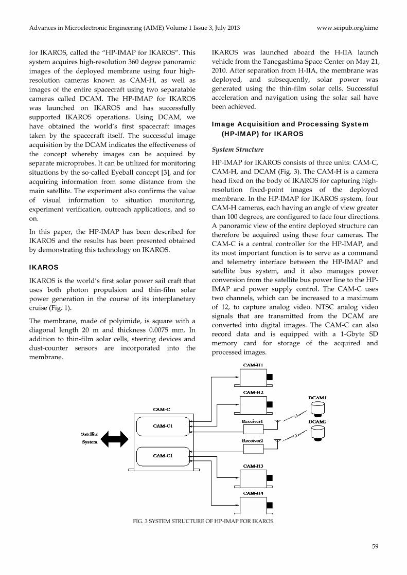
HP-IMAP for IKAROS consists of three units: CAM-C, CAM-H, and DCAM (Fig. 3). The CAM-H is a camera head fixed on the body of IKAROS for capturing high-resolution fixed-point images of the deployed membrane. In the HP-IMAP for IKAROS system, four CAM-H cameras, each having an angle of view greater than 100 degrees, are configured to face four directions. A panoramic view of the entire deployed structure can therefore be acquired using these four cameras. The CAM-C is a central controller for the HP-IMAP, and its most important function is to serve as a command and telemetry interface between the HP-IMAP and satellite bus system, and it also manages power conversion from the satellite bus power line to the HP-IMAP and power supply control. The CAM-C uses two channels, which can be increased to a maximum of 12, to capture analog video. NTSC analog video signals that are transmitted from the DCAM are converted into digital images. The CAM-C can also record data and is equipped with a 1-Gbyte SD memory card for storage of the acquired and processed images.
FIG. 3 SYSTEM STRUCTURE OF HP-IMAP FOR IKAROS.
www.seipub.org/aime Advances in Microelectronic Engineering (AIME) Volume 1 Issue 3, July 2013
60
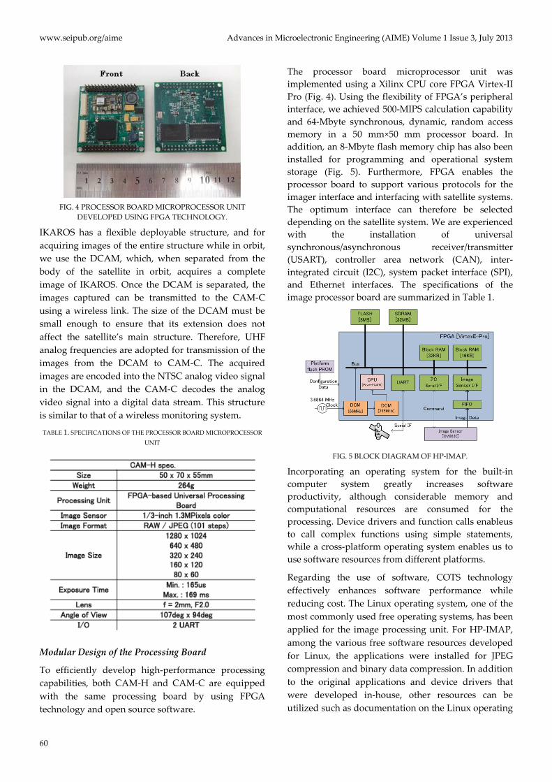
FIG. 4 PROCESSOR BOARD MICROPROCESSOR UNIT
DEVELOPED USING FPGA TECHNOLOGY.
IKAROS has a flexible deployable structure, and for acquiring images of the entire structure while in orbit, we use the DCAM, which, when separated from the body of the satellite in orbit, acquires a complete image of IKAROS. Once the DCAM is separated, the images captured can be transmitted to the CAM-C using a wireless link. The size of the DCAM must be small enough to ensure that its extension does not affect the satellite’s main structure. Therefore, UHF analog frequencies are adopted for transmission of the images from the DCAM to CAM-C. The acquired images are encoded into the NTSC analog video signal in the DCAM, and the CAM-C decodes the analog video signal into a digital data stream. This structure is similar to that of a wireless monitoring system.
TABLE 1. SPECIFICATIONS OF THE PROCESSOR BOARD MICROPROCESSOR UNIT
Modular Design of the Processing Board
To efficiently develop high-performance processing capabilities, both CAM-H and CAM-C are equipped with the same processing board by using FPGA technology and open source software.
The processor board microprocessor unit was implemented using a Xilinx CPU core FPGA Virtex-II Pro (Fig. 4). Using the flexibility of FPGA’s peripheral interface, we achieved 500-MIPS calculation capability and 64-Mbyte synchronous, dynamic, random access memory in a 50 mm×50 mm processor board. In addition, an 8-Mbyte flash memory chip has also been installed for programming and operational system storage (Fig. 5). Furthermore, FPGA enables the processor board to support various protocols for the imager interface and interfacing with satellite systems. The optimum interface can therefore be selected depending on the satellite system. We are experienced with the installation of universal synchronous/asynchronous receiver/transmitter (USART), controller area network (CAN), inter-integrated circuit (I2C), system packet interface (SPI), and Ethernet interfaces. The specifications of the image processor board are summarized in Table 1.
FIG. 5 BLOCK DIAGRAM OF HP-IMAP.
Incorporating an operating system for the built-in computer system greatly increases software productivity, although considerable memory and computational resources are consumed for the processing. Device drivers and function calls enableus to call complex functions using simple statements, while a cross-platform operating system enables us to use software resources from different platforms.
Regarding the use of software, COTS technology effectively enhances software performance while reducing cost. The Linux operating system, one of the most commonly used free operating systems, has been applied for the image processing unit. For HP-IMAP, among the various free software resources developed for Linux, the applications were installed for JPEG compression and binary data compression. In addition to the original applications and device drivers that were developed in-house, other resources can be utilized such as documentation on the Linux operating
Advances in Microelectronic Engineering (AIME) Volume 1 Issue 3, July 2013 www.seipub.org/aime
61
system. These resources and free software therefore help reducing the development costs, work load, and development time for the on-orbit system.
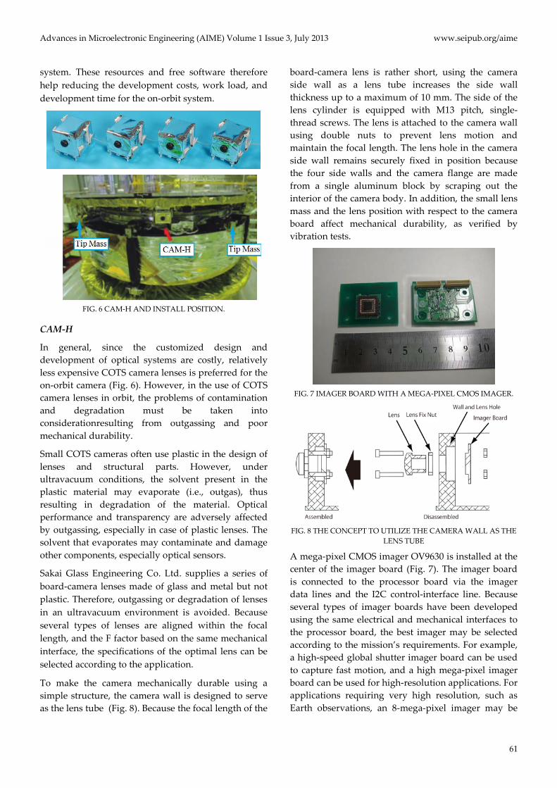
FIG. 6 CAM-H AND INSTALL POSITION.
CAM-H
In general, since the customized design and development of optical systems are costly, relatively less expensive COTS camera lenses is preferred for the on-orbit camera (Fig. 6). However, in the use of COTS camera lenses in orbit, the problems of contamination and degradation must be taken into considerationresulting from outgassing and poor mechanical durability.
Small COTS cameras often use plastic in the design of lenses and structural parts. However, under ultravacuum conditions, the solvent present in the plastic material may evaporate (i.e., outgas), thus resulting in degradation of the material. Optical performance and transparency are adversely affected by outgassing, especially in case of plastic lenses. The solvent that evaporates may contaminate and damage other components, especially optical sensors.
Sakai Glass Engineering Co. Ltd. supplies a series of board-camera lenses made of glass and metal but not plastic. Therefore, outgassing or degradation of lenses in an ultravacuum environment is avoided. Because several types of lenses are aligned within the focal length, and the F factor based on the same mechanical interface, the specifications of the optimal lens can be selected according to the application.
To make the camera mechanically durable using a simple structure, the camera wall is designed to serve as the lens tube (Fig. 8). Because the focal length of the
board-camera lens is rather short, using the camera side wall as a lens tube increases the side wall thickness up to a maximum of 10 mm. The side of the lens cylinder is equipped with M13 pitch, single-thread screws. The lens is attached to the camera wall using double nuts to prevent lens motion and maintain the focal length. The lens hole in the camera side wall remains securely fixed in position because the four side walls and the camera flange are made from a single aluminum block by scraping out the interior of the camera body. In addition, the small lens mass and the lens position with respect to the camera board affect mechanical durability, as verified by vibration tests.
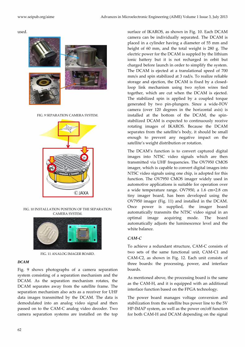
FIG. 7 IMAGER BOARD WITH A MEGA-PIXEL CMOS IMAGER.
FIG. 8 THE CONCEPT TO UTILIZE THE CAMERA WALL AS THE
LENS TUBE
A mega-pixel CMOS imager OV9630 is installed at the center of the imager board (Fig. 7). The imager board is connected to the processor board via the imager data lines and the I2C control-interface line. Because several types of imager boards have been developed using the same electrical and mechanical interfaces to the processor board, the best imager may be selected according to the mission’s requirements. For example, a high-speed global shutter imager board can be used to capture fast motion, and a high mega-pixel imager board can be used for high-resolution applications. For applications requiring very high resolution, such as Earth observations, an 8-mega-pixel imager may be
www.seipub.org/aime Advances in Microelectronic Engineering (AIME) Volume 1 Issue 3, July 2013
62
used.
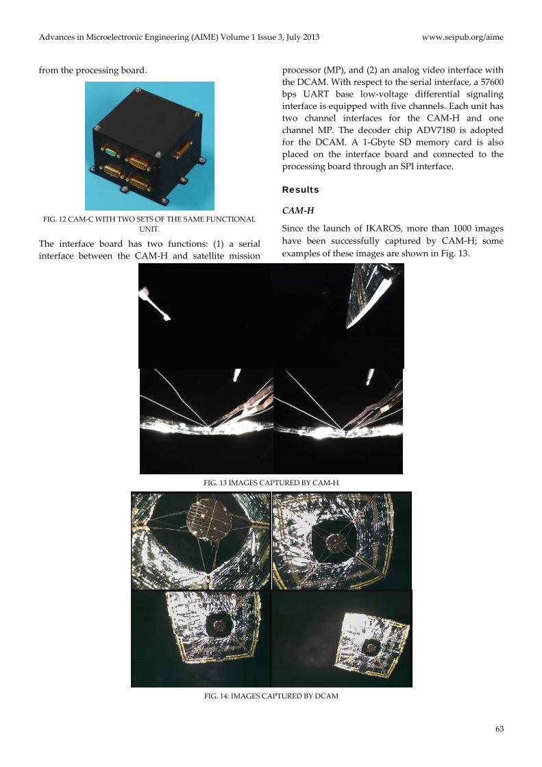
FIG. 9 SEPARATION CAMERA SYSTEM.
FIG. 10 INSTALLATION POSITION OF THE SEPARATION
CAMERA SYSTEM.
FIG. 11 ANALOG IMAGER BOARD.
DCAM
Fig. 9 shows photographs of a camera separation system consisting of a separation mechanism and the DCAM. As the separation mechanism rotates, the DCAM separates away from the satellite frame. The separation mechanism also acts as a receiver for UHF data images transmitted by the DCAM. The data is demodulated into an analog video signal and then passed on to the CAM-C analog video decoder. Two camera separation systems are installed on the top
surface of IKAROS, as shown in Fig. 10. Each DCAM camera can be individually separated. The DCAM is placed in a cylinder having a diameter of 55 mm and height of 60 mm, and the total weight is 280 g. The electric power for the DCAM is suppled by the lithium ionic battery but it is not recharged in orbit but charged before launch in order to simplify the system. The DCAM is ejected at a translational speed of 700 mm/s and spin stabilized at 3 rad/s. To realize reliable storage and ejection, the DCAM is fixed by a closed-loop link mechanism using two nylon wires tied together, which are cut when the DCAM is ejected. The stabilized spin is applied by a coupled torque generated by two pin-plungers. Since a wide-FOV camera (over 120 degrees in the horizontal axis) is installed at the bottom of the DCAM, the spin-stabilized DCAM is expected to continuously receive rotating images of IKAROS. Because the DCAM separates from the satellite’s body, it should be small enough to prevent any negative impact on the satellite’s weight distribution or rotation.
The DCAM’s function is to convert captured digital images into NTSC video signals which are then transmitted via UHF frequencies. The OV7950 CMOS imager, which is capable to convert digital images into NTSC video signals using one chip, is adopted for this function. The OV7950 CMOS imager widely used in automotive applications is suitable for operation over a wide temperature range. OV7950, a 1.6 cm×2.8 cm tiny imager board, has been developed using the OV7950 imager (Fig. 11) and installed in the DCAM. Once power is supplied, the imager board automatically transmits the NTSC video signal in an optimal image acquiring mode. The board automatically adjusts the luminescence level and the white balance.
CAM-C
To achieve a redundant structure, CAM-C consists of two sets of the same functional unit, CAM-C1 and CAM-C2, as shown in Fig. 12. Each unit consists of three boards: the processing, power, and interface boards.
As mentioned above, the processing board is the same as the CAM-H, and it is equipped with an additional interface function based on the FPGA technology.
The power board manages voltage conversion and stabilization from the satellite bus power line to the 5V HP-IMAP system, as well as the power on/off function for both CAM-H and DCAM depending on the signal
Advances in Microelectronic Engineering (AIME) Volume 1 Issue 3, July 2013 www.seipub.org/aime
63
from the processing board.
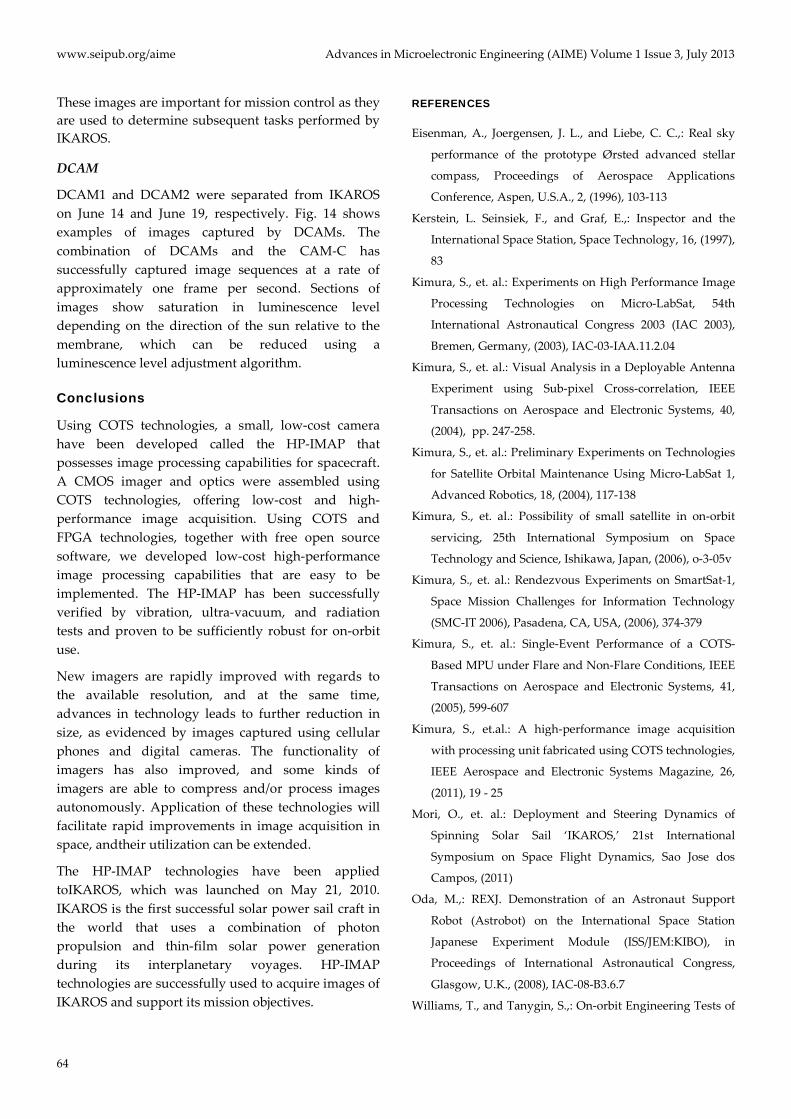
FIG. 12 CAM-C WITH TWO SETS OF THE SAME FUNCTIONAL
UNIT.
The interface board has two functions: (1) a serial interface between the CAM-H and satellite mission
processor (MP), and (2) an analog video interface with the DCAM. With respect to the serial interface, a 57600 bps UART base low-voltage differential signaling interface is equipped with five channels. Each unit has two channel interfaces for the CAM-H and one channel MP. The decoder chip ADV7180 is adopted for the DCAM. A 1-Gbyte SD memory card is also placed on the interface board and connected to the processing board through an SPI interface.
Results
CAM-H
Since the launch of IKAROS, more than 1000 images have been successfully captured by CAM-H; some examples of these images are shown in Fig. 13.
FIG. 13 IMAGES CAPTURED BY CAM-H
FIG. 14: IMAGES CAPTURED BY DCAM
www.seipub.org/aime Advances in Microelectronic Engineering (AIME) Volume 1 Issue 3, July 2013
64
These images are important for mission control as they are used to determine subsequent tasks performed by IKAROS.
DCAM
DCAM1 and DCAM2 were separated from IKAROS on June 14 and June 19, respectively. Fig. 14 shows examples of images captured by DCAMs. The combination of DCAMs and the CAM-C has successfully captured image sequences at a rate of approximately one frame per second. Sections of images show saturation in luminescence level depending on the direction of the sun relative to the membrane, which can be reduced using a luminescence level adjustment algorithm.
Conclusions
Using COTS technologies, a small, low-cost camera have been developed called the HP-IMAP that possesses image processing capabilities for spacecraft. A CMOS imager and optics were assembled using COTS technologies, offering low-cost and high-performance image acquisition. Using COTS and FPGA technologies, together with free open source software, we developed low-cost high-performance image processing capabilities that are easy to be implemented. The HP-IMAP has been successfully verified by vibration, ultra-vacuum, and radiation tests and proven to be sufficiently robust for on-orbit use.
New imagers are rapidly improved with regards to the available resolution, and at the same time, advances in technology leads to further reduction in size, as evidenced by images captured using cellular phones and digital cameras. The functionality of imagers has also improved, and some kinds of imagers are able to compress and/or process images autonomously. Application of these technologies will facilitate rapid improvements in image acquisition in space, andtheir utilization can be extended.
The HP-IMAP technologies have been applied toIKAROS, which was launched on May 21, 2010. IKAROS is the first successful solar power sail craft in the world that uses a combination of photon propulsion and thin-film solar power generation during its interplanetary voyages. HP-IMAP technologies are successfully used to acquire images of IKAROS and support its mission objectives.
REFERENCES
Eisenman, A., Joergensen, J. L., and Liebe, C. C.,: Real sky
performance of the prototype Ørsted advanced stellar
compass, Proceedings of Aerospace Applications
Conference, Aspen, U.S.A., 2, (1996), 103-113
Kerstein, L. Seinsiek, F., and Graf, E.,: Inspector and the
International Space Station, Space Technology, 16, (1997),
83
Kimura, S., et. al.: Experiments on High Performance Image
Processing Technologies on Micro-LabSat, 54th
International Astronautical Congress 2003 (IAC 2003),
Bremen, Germany, (2003), IAC-03-IAA.11.2.04
Kimura, S., et. al.: Visual Analysis in a Deployable Antenna
Experiment using Sub-pixel Cross-correlation, IEEE
Transactions on Aerospace and Electronic Systems, 40,
(2004), pp. 247-258.
Kimura, S., et. al.: Preliminary Experiments on Technologies
for Satellite Orbital Maintenance Using Micro-LabSat 1,
Advanced Robotics, 18, (2004), 117-138
Kimura, S., et. al.: Possibility of small satellite in on-orbit
servicing, 25th International Symposium on Space
Technology and Science, Ishikawa, Japan, (2006), o-3-05v
Kimura, S., et. al.: Rendezvous Experiments on SmartSat-1,
Space Mission Challenges for Information Technology
(SMC-IT 2006), Pasadena, CA, USA, (2006), 374-379
Kimura, S., et. al.: Single-Event Performance of a COTS-
Based MPU under Flare and Non-Flare Conditions, IEEE
Transactions on Aerospace and Electronic Systems, 41,
(2005), 599-607
Kimura, S., et.al.: A high-performance image acquisition
with processing unit fabricated using COTS technologies,
IEEE Aerospace and Electronic Systems Magazine, 26,
(2011), 19 - 25
Mori, O., et. al.: Deployment and Steering Dynamics of
Spinning Solar Sail ‘IKAROS,’ 21st International
Symposium on Space Flight Dynamics, Sao Jose dos
Campos, (2011)
Oda, M.,: REXJ. Demonstration of an Astronaut Support
Robot (Astrobot) on the International Space Station
Japanese Experiment Module (ISS/JEM:KIBO), in
Proceedings of International Astronautical Congress,
Glasgow, U.K., (2008), IAC-08-B3.6.7
Williams, T., and Tanygin, S.,: On-orbit Engineering Tests of
Advances in Microelectronic Engineering (AIME) Volume 1 Issue 3, July 2013 www.seipub.org/aime
65
the AERcam Sprint Robotic Camera Vehicle, Adv.
Astronaut. Sci., 99, (1998), 1001-1020
Shinichi Kimura received the B. S. degree in chemistry on drug manufacturing from Tokyo University, Tokyo, Japan, in 1988 and M. S. and Ph. D. degrees in pharmacology from Tokyo University, Tokyo, Japan, in 1990 and 1993 respectively. In 1993 he joined the Communications Research
Laboratory (which was converted to the National Institute of Information and Communication Technology in 2004) and has been the group leader of Smart Satellite Technology Group since 2004. He holds an additional post of a guest associate professor of The University of Elecreo-Communications. In 2007, he moved to Tokyo University of Science as a associated professor, and in 2012 he became professor. He has been engaged in the space robotics and autonomous control technologies to maintain the telecommunication satellites. He made experiments on Manipulator Flight Demonstration on STS-87, Engineering Test Satellite VII which is the first tele-robotic satellite, visual analysis experiment of deployable antenna (LDREX) and Micro-LabSat, visual monitoring system for the IKAROS
(Interplanetary Kite-craft Accelerated by Radiation Of the Sun). He is engaging various missions and developing on-orbit motoring cameras.
Masato Terakura received M.E. degree in electronic engineering from Tokyo University of Science, Japan, in 2011, and B.E. degree in 2009. He is a doctoral student at Tokyo University of Science in Japan. His research interests include computer system, digital camera and satellite system.
Hirotaka Sawada received his Master's degree of engineering in 2001 and the Ph.D. in 2004 from Tokyo Institute of Technology. He is an engineer of JAXA Space Exploration Center, Japan Aerospace Exploration Agency. He was also PI of solar power sail deployment
mission, and monitor/separation camera system of the IKAROS project. He is currently working in HAYABUSA2 project team as PI of the sampling mission and the separation camera mission. His research interestsinclude space robotics, spacecraft systems/dynamics/control.