Embed Size (px)
Citation preview
Nanoscale
PAPER
Cite this: Nanoscale, 2016, 8, 12294
Received 17th March 2016,Accepted 31st May 2016
DOI: 10.1039/c6nr02245f
www.rsc.org/nanoscale
Highly transparent, low-haze, hybrid cellulosenanopaper as electrodes for flexible electronics†
Xuezhu Xu,a,b,c Jian Zhou,c Long Jiang,*a,b Gilles Lubineau,*c Tienkhee Ng,d
Boon S. Ooi,d Hsien-Yu Liao,d Chao Shen,d Long Chene and J. Y. Zhuf
Paper is an excellent candidate to replace plastics as a substrate for flexible electronics due to its low cost,
renewability and flexibility. Cellulose nanopaper (CNP), a new type of paper made of nanosized cellulose
fibers, is a promising substrate material for transparent and flexible electrodes due to its potentially high
transparency and high mechanical strength. Although CNP substrates can achieve high transparency, they
are still characterized by high diffuse transmittance and small direct transmittance, resulting in high
optical haze of the substrates. In this study, we proposed a simple methodology for large-scale pro-
duction of high-transparency, low-haze CNP comprising both long cellulose nanofibrils (CNFs) and short
cellulose nanocrystals (CNCs). By varying the CNC/CNF ratio in the hybrid CNP, we could tailor its total
transmittance, direct transmittance and diffuse transmittance. By increasing the CNC content, the optical
haze of the hybrid CNP could be decreased and its transparency could be increased. The direct transmit-
tance and optical haze of the CNP were 75.1% and 10.0%, respectively, greatly improved from the values
of previously reported CNP (31.1% and 62.0%, respectively). Transparent, flexible electrodes were fabri-
cated by coating the hybrid CNP with silver nanowires (AgNWs). The electrodes showed a low sheet
resistance (minimum 1.2 Ω sq−1) and a high total transmittance (maximum of 82.5%). The electrodes were
used to make a light emitting diode (LED) assembly to demonstrate their potential use in flexible displays.
1. Introduction
Flexible, highly transparent and conductive electrodes arerequired in next-generation flexible electronics in applicationssuch as flexible large-area displays, touch screens,1 LED lightsources2 and solar energy devices.3 Indium tin oxide (ITO) haslong been used to make glass-based transparent electrodes.The drawbacks of these traditional electrodes are numerous:they are brittle4 and expensive; they are made from limited/non-renewable raw materials; their manufacturing processesare environmentally damaging. ITO-based electrodes are not
well suited to flexible electronics because the channel crackingin the brittle ITO coating during fracture dramaticallydecreases the conductivity of the electrodes, rendering themnon-operational. Poly(3,4-ethylenedioxythiophene)/polystyrenesulfonate (PEDOT/PSS),5,6 carbon nanotubes (CNTs), grapheneand silver nanowires (AgNWs)7–10 have been coated on flexiblepolymer substrates with the aim of replacing ITO/glass electro-des. These new flexible electrodes not only exhibit comparableoptical properties but also offer additional advantages includ-ing light weight, stretchability, high electrical conductivity,11
and good processibility (e.g., they are rollable, heatable andprintable). However, the commonly used polymer substratematerials, e.g., polyethylene terephthalate (PET), polyimide(PI), and various fluoropolymers, are all made from petroleum-based chemicals. Environmental concerns and uncertaintiesabout oil price and availability have made it an increasinglyattractive option to produce the materials from bioresources.12
Very recently, flexible electronics on cellulose nanopaper sub-strate have been developed.13 The nanopaper substrate ismade using a method similar to the traditional paper makingprocess. However, rather than using microsized cellulosefibers in traditional paper, cellulose nanofibers isolated fromlignocellulosic biomass are used to produce the nanopaper.
Two types of cellulose nanofibers have been produced fromvarious bio-resources. One is cellulose nanofibrils (CNFs),
†Electronic supplementary information (ESI) available. See DOI: 10.1039/C6NR02245F
aNorth Dakota State University, Department of Mechanical Engineering, USAbProgram of Materials and Nanotechnology, Fargo, ND 58102, USA.
E-mail: [email protected] Abdullah University of Science and Technology (KAUST), Physical Science and
Engineering Division, Mechanical Engineering, COHMAS Laboratory,
Thuwal 23955-6900, Saudi Arabia. E-mail: [email protected] Abdullah University of Science and Technology (KAUST), Physical Science and
Engineering Division, Electrical Engineering, Photonics Laboratory,
Thuwal 23955-6900, Saudi ArabiaeKing Abdullah University of Science and Technology (KAUST), Advanced
Nanofabrication, Imaging and Characterization Core Laboratory,
Thuwal 23955-6900, Saudi ArabiafForest Products Laboratory, USDA Forest Service, Madison, Wisconsin 53726, USA
12294 | Nanoscale, 2016, 8, 12294–12306 This journal is © The Royal Society of Chemistry 2016
Publ
ishe
d on
01
June
201
6. D
ownl
oade
d by
Uni
vers
ity o
f W
isco
nsin
- M
adis
on o
n 28
/07/
2016
21:
17:3
1.
View Article OnlineView Journal | View Issue
which are long, flexible, often-entangled fibrils containingboth crystalline and amorphous cellulose. The other is needle-shaped cellulose nanocrystals (CNCs), a product from acidhydrolysis of cellulosic fibers to remove amorphous cellulose.CNFs can be isolated from different types of lignocellulosicbiomass through direct mechanical fibrillation,14,15 mechan-ical fibrillation after enzymatic hydrolysis,16,17 mechanicalfibrillation after 2,2,6,6-tetramethylpiperidine-1-oxyl radical(TEMPO)-mediated oxidation,18 carboxymethylation19 or acidtreatment.20 Production of CNCs generally involves hydrolysisof cellulosic fibers by strong acids (e.g., sulfuric and hydro-chloride acids).21 While wood pulp is the most widely usedfeedstock to produce cellulose nanofibers, many other naturalfibers have also been used.22 A recent review paper describesvarious production methods for CNFs and CNCs.23,24 Researchon cellulose nanofibers has grown in recent years due to theirhigh strength, high modulus, large aspect ratio/surface area,low density, rich surface chemistry (i.e. various chemicalsurface modification methods), optical properties, andrenewability.13,25–28
CNC- or CNF-reinforced polymer sheets and cellulose nano-paper (CNP) have been tested as substrates for transparent andflexible electrodes.13,13,29–36 For the first type, the cellulosenanofibers are used as reinforcements in polymers to producetransparent composite substrates.37–39 For the second type, all-CNF CNP (based on either unmodified or TEMPO modifiedCNFs) as a transparent substrate has been developed using afiltration and pressing process.16,29,30,40 Compared to polymerbased substrates, CNP shows the advantage of high thermalstability. For example, Hsieh et al. found that the thermaldegradation temperature of CNP was 300 °C. No color changeand dimensional changes (e.g. shrinking, warping, twisting,etc.) were observed after 30 min at 200 °C.41 While the mechan-ical/thermal properties and transparency of the CNP are verycompetitive, many of the products also exhibit high opticalhaze, which results from strong diffuse transmittance causedby light scattering from large nanofiber bundles and/or poreswithin the nanopaper.11,31,41,42
The total transparency, Ttotal, of a medium is defined as theratio of transmitted radiant power to incident radiant power. Itis the sum of the direct transmittance, Tdirect, and the diffusetransmittance, Tdiffuse such that Ttotal = Tdirect + Tdiffuse. Thepercentage, defined as Tdiffuse/Ttotal × 100%, quantifies theratio of light that is transmitted in a diffuse manner and is ameasurement of optical haze. The CNP prepared by Hu’sgroup has a Ttotal up to 90% (at 600 nm wavelength) and aTdirect as low as ∼20%, resulting in a product with high trans-parency but also high haze.11,37,43–46 Nogi et al. showed thatthe scattering (and consequently the haze) can be largelydecreased by polishing or coating the surface of the nanopaper(Tdirect increased to 71.6% after the treatments).46 While highhaze is a useful feature for applications such as skylights,indoor lighting and solar cells,31 which often benefit fromdiffuse transmittance, CNP with high haze is not suitable forapplications that require high transparency and clarity, e.g.,flexible displays and touch screens.
An extensive literature review reveals that current free-stand-ing transparent nanopaper substrates are mostly based onwood-based CNFs or a mixture of CNFs and micro-sized cellu-lose fibers, and many of them exhibit high haze.13,31,41,44,47,48
TEMPO-oxidation of CNFs has been shown to refine the nano-fibers and therefore produce CNP with improved transparencyand haze.16,35,42,48–51 Yet, it is still difficult to tailor the opticalproperties of the obtained CNP for different applications. Ourgoal in this study is to develop a facile method to produce CNPwith a wide range of optical properties using CNFs and CNCssimultaneously. By varying the CNC/CNF ratio, we can controlthe transparency and haze of the hybrid CNP. We demonstrate itsapplication as a transparent electrode by coating it with a layer ofsilver nanowires (AgNWs). The electrode exhibits high electricalconductivity that is stable under large bending deformation,which satisfies the requirement for flexible/wearable electronics.
2. Materials and methods2.1. Materials
The CNCs and CNFs were produced from a dry lap bleachedkraft eucalyptus pulp at USDA Forest Service, Forest ProductsLaboratory, Madison, WI. The CNCs were produced by acidhydrolysis using sulfuric acid of 58 wt% at 56 °C for 100 minas described previously.52 The acid form of the resultant CNCswas used for the present study with a sulfur content of 6.8 mgg−1 and a surface charge (zeta potential) of −45 mV measured bya zeta potential analyzer (Nanobrook Omni, Brookhaven Instru-ments, Holtsville, NY) based on monitoring electrophoreticmobility using Phase Analysis Light Scattering (PALS). The CNFswere produced through mechanical fibrillation of the pulp fibersin a SuperMassColloider (Model: MKZA6-2, Disk Model: MKGA6-80#, Masuko Sangyo Co., Ltd, Japan). Fibrillation was conductedat 2% solids loading for 5 h with a disk gap setting of −100 µmas described previously.14 The surface charge of the CNFs wasminimal. The mean sizes and crystallinities (CrI) of the CNFsand CNCs were measured previously as follows: 20 ± 14 nm (dia-meter) and 1030 ± 334 nm (length), 64.4% (CrI) for the CNFs;19 ± 5 nm (diameter) and 151 ± 39 nm (length), 81.0% (CrI) forthe CNCs.53,54 Both types of nanofiber were provided in the formof aqueous suspensions and were used as received (concen-tration: CNCs = 5.7 wt%, CNFs = 1.8 wt%). Micro-sized cellulosefibers were obtained from commercial filter paper (WhatmanInternational Ltd., grade 4, diameter 32 cm) by dispersing it inwater using a food blender. Polyvinylpyrrolidone (PVP, Mw =1 300 000), ethylene glycol (EG), sodium chloride (NaCl), silvernitrate (AgNO3) and ammonium hydroxide (NH4OH) were usedto synthesize the silver nanowires (AgNWs). All chemicals werepurchased from Sigma-Aldrich.
2.2. Fabrication of CNP
CNFs and CNCs with predetermined weight ratios (Table 1)were mixed by an ultrasonic processor (Cole-Parmer) for 5 min(250 W, room temperature). The solid content of the CNF/CNCmixtures was kept constant at 0.2 wt% in all formulations. The
Nanoscale Paper
This journal is © The Royal Society of Chemistry 2016 Nanoscale, 2016, 8, 12294–12306 | 12295
Publ
ishe
d on
01
June
201
6. D
ownl
oade
d by
Uni
vers
ity o
f W
isco
nsin
- M
adis
on o
n 28
/07/
2016
21:
17:3
1.
View Article Online
mixtures were then filtered using a polyethylene filter (30 µmpore size) to remove remaining nanofiber aggregates. Wet CNPwas produced using vacuum assisted filtration, a typical nano-paper-making technique.55 Briefly, the mixtures were firstvacuum-filtered using Anopore membranes (0.02 µm pore size,Whatman International Ltd) in a Wheaton funnel. Theobtained wet nanopaper was then removed from the funneland sandwiched between two membranes under pressure(about 0.36 kPa) and dried in a vacuum oven at 130 °C for30 min. For comparison, “micropaper” was also fabricated fol-lowing exactly the same procedure using the micro-sized cellu-lose fibers obtained from the Whatman filter paper.
We recognize that the CNF/CNC ratio in the produced CNPmay be slightly different from the initial ratio selected formixing because some nanofibers could go through the 20 nmpores in the filter (it might be more difficult for CNFs to do sobecause of their much larger length and their bundles/net-works). However, we believe the chance for this to happen issmall because the nanofibers need to be vertical to the filter togo through the pores. Moreover, if two fibers approach thesame pore at the same time, the pore is blocked and no fiberscan pass through. Therefore, throughout this paper we still usethe initial CNF/CNC ratio to identify the produced CNP.
2.3. Synthesis of AgNWs
0.334 g PVP powder was completely dissolved in 25 mL EG bymild stirring at 170 °C for ∼30 min. A NaCl solution in EG(50 μL, 0.43 M) and an AgNO3 solution in EG (50 μL, 0.43 M)were simultaneously injected into the PVP solution and themixture was stirred for 15 min to grow silver nanoparticleseeds. Another AgNO3 solution in EG (10 mL, 0.12 M) wasadded dropwise for 12 min while stirring. The mixture wasstirred for an additional 4 min. The reaction mixture was thencooled to room temperature (∼ 50 °C h−1) and ∼100 mL waterwas added to stop the reaction. To remove the impurities,2 mL aqueous NH4OH was added to the mixture to dissolvethe residual silver chloride (AgCl) generated during the reac-tion. AgNWs were imaged by a scanning electron microscope(SEM, Quanta 600 from FEI Company) and a transmissionelectron microscope (TEM, Titan G2 80-300 CT from FEICompany) to obtain their average diameters and lengths(Fig. S1†). The concentration of the as-prepared AgNW suspen-sion was measured to be 0.028 wt%.
2.4. Fabrication of transparent CNP electrode
The process to fabricate transparent AgNW/CNP electrodes wassimilar to that of producing CNP. We first prepared five newAgNW suspensions by diluting 0.1, 0.5, 1, 2, and 3 g of the as-synthesized AgNW suspension in 20 g water. Then wet CNP wasproduced using vacuum-assisted filtration. With the wet CNPintact in the funnel, one of the new AgNW suspensions wasadded into the funnel and the filtration process continued untilno liquid was left in the funnel. The obtained AgNW/CNP bilayerstructure was dried using the method described in section 2.2 toeventually produce a transparent CNP electrode. AgNW arealdensity (mg m−2) on the CNP was calculated based on the con-centration and volume of the added AgNW suspensions.
2.5. LED demonstration using AgNWs/CNP electrode
A patterned AgNW layer was deposited on the surface of CNPby placing a polyvinylidene fluoride (PVDF) mask on the wetnanopaper before filtering the AgNW suspension. A commer-cially available aluminum gallium indium phosphide(AlGaInP)-based red LED (from Luwa System Inc.) wasembedded between two patterned CNP electrodes to produceCNP-based LED devices. The electronic characteristics of thedevices were measured using a customized light–current–voltage (L–I–V) testing system comprising a Keithley 2400source meter, a Newport 2936C optical power meter and anOcean optics 65000+ spectrometer.
2.6. Characterizations
Nanostructures of the prepared CNP, AgNWs and AgNWs/CNPelectrodes were studied using a SEM (Quanta 600) operating at5 or 10 kV and a TEM (Titan G2 80-300 CT) operating at 300 kV.Optical properties of the CNP and AgNWs/CNP electrodes weremeasured using a UV-VIS-NIR (UV-3600) spectrophotometerequipped with an ISR-3100 integrating sphere from ShimadzuCompany. Transmittance of the samples was measured between200–1200 nm wavelengths. The average values with standarddeviations were calculated based on three measurements. Allthe digital photos in this study were taken by a consumerdigital camera without using any polarizer and filter.
Sheet resistances (Rs) of the AgNW/CNP electrodes weremeasured using a CMT-SR2000N four-probe system (probespace 1 mm) from Materials Development Corporation.Measurements were taken at 10 different locations of eachsample and the average value along with standard deviationwas reported. To evaluate the stability of the electrical perform-ance of the electrodes under deformation, the electrical resist-ance was measured in situ during a cyclic folding test on a4 mm × 10 mm electrode. Two copper wires (15 cm long and0.004 inch in diameter; C510 alloy, United Wire TechnologiesInc.) were soldered onto the electrode using silver epoxy (Cir-cuitworks CW2400 from ITW Chemtronics). A schematic illus-tration of the specimen was shown later in the Results andDiscussion (Fig. 7A). The electrical resistance was measured byan Agilent U1252B multimeter, and the data were recorded bya computer. The folding action on the electrodes was provided
Table 1 Optical properties of the CNP and the “micropaper”
CNF : CNCratio
CNCcontent(wt%)
Rdiffuse at600 nm(%)
Tdirect at600 nm(%)
Ttotal at600 nm(%)
Haze(%)
10 : 0 0 10.9 31.1 ± 0.5 81.8 62.010 : 2 16.7 13.5 36.6 ± 0.2 82.4 55.610 : 6 37.5 9.5 61.6 ± 0.2 79.3 22.310 : 10 50.0 8.9 65.2 ± 0.3 83.8 22.16 : 10 62.5 7.4 72.5 ± 0.7 83.7 13.52 : 10 83.3 6.0 75.1 ± 0.4 83.4 10.00 : 10 100.0 5.2 74.2 ± 0.5 86.4 14.1“Micropaper” 56.0 2.8 ± 0.4 32.8 91.4
Paper Nanoscale
12296 | Nanoscale, 2016, 8, 12294–12306 This journal is © The Royal Society of Chemistry 2016
Publ
ishe
d on
01
June
201
6. D
ownl
oade
d by
Uni
vers
ity o
f W
isco
nsin
- M
adis
on o
n 28
/07/
2016
21:
17:3
1.
View Article Online
by an Instron 5944. The electrodes were also subjected to insitu resistance measurement under cyclic tension using thesame Instron tester (5 N load cell). At least ten rectangularspecimens (4 mm × 16 mm) were measured for each CNP.
Atomic force microscopy (AFM, Asylum MFP-3D) wasemployed to acquire height and phase images of the nanopa-per surfaces. Probes (FESP from Bruker) with a spring constantof 2.8 N m−1 were used under the tapping mode. Average rootmean square roughness (RRMS) was obtained based on AFMscanning on three different areas of the nanopaper. RRMS ofthe surfaces was calculated using Gwyddion software. Porosityand bulk density of the samples were measured using a Micro-meritics AutoPore IV mercury porosimeter. The measurementswere performed between 0.1 and 45 kPa after outgassing thesample for 2 hours at ambient temperature, and the data wereanalyzed using AutoPore IV 9500 (version 1.09) software. Fromthe bulk density ρb and the skeletal density ρs, the overall poro-sity, Φ (dimensionless), and the specific pore volume, VP (cm3
g−1), of the materials could be calculated as:
Φ ¼ 1� ρbρs
ð1Þ
VP ¼ 1ρb
� 1ρs
ð2Þ
3. Results and discussion3.1. Optical properties of CNP
Fig. 1A compares the visual appearance of the aqueous suspen-sions of CNFs, CNCs and their mixtures. The micro-sized cellu-lose fibers isolated from Whatman filter paper were alsodispersed in water at the same concentration for comparison.Due to their large diameter and length (diameter ≥ 30 µm;length ≥ 1000 µm), the micro-sized fibers precipitated quicklyin water after the stirring was stopped (#1 in Fig. 1A).49 By con-trast, CNFs and CNCs both formed stable dispersions in water,with the former being translucent (#2) and the latter transpar-ent (#8). The difference in transparency can be attributed tothe presence of relatively large CNF bundles and networks54 inthe CNF suspension that scattered more light than the indivi-dually dispersed CNCs in the CNC suspension. The CNFbundles were formed through hydrogen bonding between the–OH groups on the fiber surface, and the networks werecaused by physical entanglement between the fibers. By con-trast, most CNCs in the suspension remained individually dis-persed due to electrostatic repulsion originating from thesulfate (–OSO3
−) groups on the fiber surfaces.56 The transpar-ency of the mixed CNC/CNF suspensions increased withincreasing CNC content (#3 through #7). This could be attribu-ted to the fact that CNFs at lower concentrations exhibitweaker tendency to bundle and network. In addition, the
Fig. 1 Optical images of various fiber suspensions (under natural light) and their direct transmittance as hybrid nanopapers; (A) from left to right,#1: suspension of the micron-sized cellulose fibers; #2 to #8: mixed CNF/CNC suspensions with 0%, 16.7%, 37.5%, 50.0%, 62.5%, 83.3% and 100.0%of CNCs. The solid content of all the suspensions was 0.2 wt%. Suspensions #2 to #8 are stable for at least 24 hours. (B) Visual appearance of apiece of hybrid CNP (62.5% CNCs); (C) direct transmittance of the “micropaper”, all-CNF CNP, and the hybrid CNP (83.3% CNCs); (D) Direct transmit-tance as a function of the CNC content at 600 nm wavelength.
Nanoscale Paper
This journal is © The Royal Society of Chemistry 2016 Nanoscale, 2016, 8, 12294–12306 | 12297
Publ
ishe
d on
01
June
201
6. D
ownl
oade
d by
Uni
vers
ity o
f W
isco
nsin
- M
adis
on o
n 28
/07/
2016
21:
17:3
1.
View Article Online
added CNCs could also act as “spacers” to reduce the contactsbetween the CNFs and therefore hinder the CNF bundling andnetworking processes.
The transparency of the hybrid CNP follows the same trend,i.e., the transparency increases with the increasing CNCcontent. Fig. 1B shows the visual appearance of a piece ofhighly transparent hybrid CNP (62.5% CNCs). Tdirect wasmeasured between 200–1200 nm wavelength for quantificationof the optical properties. Fig. 1C compares the Tdirect of twoCNP samples (0% CNCs and 83.3% CNCs, respectively) andone “micropaper” sample. Across the entire wavelength range,the “micropaper” exhibits the lowest Tdirect (≈ 0); Tdirect of theall-CNF CNP increases significantly and it further improves forthe hybrid CNP. For instance, at 600 nm, Tdirect for the “micro-paper”, all-CNF CNP, and the hybrid CNP are 2.8%, 31.1% and75.1%, respectively. The dependence of Tdirect on the CNCcontent is shown in Fig. 1D and Table 1, which indicate thatthe transmittance increases with the increasing CNC contentinitially and tends to level off after the content exceeds 62.5%.The plateau value of Tdirect (∼75%) exceed most reportedvalues for CNF-based CNP;46 it also approaches that of poly(ethylene terephthalate) (PET, >85%),57 ITO glass (85%)58 andpure silicon oxide glass (92%). This high Tdirect is attributed to
the reduced surface roughness, porosity and internal pore sizeof the CNP after the addition of CNCs, as will be discussedbelow.
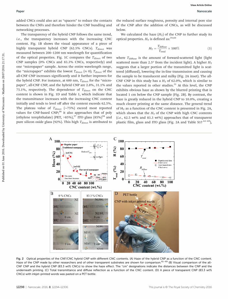
We calculated the haze (HT) of the CNP to further study itsoptical properties. HT is defined as:59,60
HT ¼ Tdiffuse
Ttotal� 100% ð3Þ
where Tdiffuse is the amount of forward-scattered light (lightscattered more than 2.5° from the incident light). A higher HT
suggests that a larger portion of the transmitted light is scat-tered (diffused), lowering the in-line transmission and causingthe sample to be translucent and milky (Fig. 2A inset). The all-CNF CNP in this study has a HT of 62.0%, which is similar tothe values reported in other studies.31 At this level, the CNPexhibits obvious haze as shown by the blurred printing that islocated 1 cm below the CNP sample (Fig. 2B). By contrast, thehaze is greatly reduced in the hybrid CNP to 10.0%, creating amuch clearer printing at the same distance. The general trendof HT as a function of the CNC content is presented in Fig. 2A,which shows that the HT of the CNP with high CNC contents(i.e., 62.5 wt% and 83.3 wt%) approaches that of transparentplastic film, glass and ITO glass (Fig. 2A and Table S1† 61–69),
Fig. 2 Optical properties of the CNF/CNC hybrid CNP with different CNC contents. (A) Haze of the hybrid CNP as a function of the CNC content.Haze of the CNP made by other researchers and of other transparent substrates are shown for comparison.61–69 (B) Visual comparison of the all-CNF CNP and the hybrid CNP (83.3 wt% CNCs) to show the haze effect. The “cm” designations indicate the distances between the CNP and theunderneath printing. (C) Total transmittance and diffuse reflection as a function of the CNC content. (D) A piece of transparent CNP (83.3 wt%CNCs) with inkjet-printed words was pasted on a PET bottle.
Paper Nanoscale
12298 | Nanoscale, 2016, 8, 12294–12306 This journal is © The Royal Society of Chemistry 2016
Publ
ishe
d on
01
June
201
6. D
ownl
oade
d by
Uni
vers
ity o
f W
isco
nsin
- M
adis
on o
n 28
/07/
2016
21:
17:3
1.
View Article Online
suggesting the potential of the hybrid CNP to replace these tra-ditional transparent materials.
While the haze of a material is mostly affected by trans-mission of light, the gloss of the material depends on howlight is reflected on the material surface. To distinguishbetween haze and gloss, we also measured the diffuse reflec-tion (Rdiffuse) of all CNP (Table 1). Rdiffuse is caused by thesurface roughness and inhomogeneity of the material. Amaterial with low Rdiffuse exhibits high gloss. Fig. 2B showsthat Rdiffuse decreases with increasing CNC content, indicatingimproved surface roughness and overall material homogeneity.In general, a combination of high Tdirect, high Ttotal, low Rdiffuseand low HT renders CNP the quality of high-transparency,high-gloss, and low-haze, which is demonstrated by the CNPin Fig. 2C. In this digital photo, a piece of circular CNP, onwhich “NDSU” and other words are printed using a commer-cial inkjet printer, is pasted on the surface of a PET bottle. Thephoto shows negligible visual difference between the CNP andthe plastic, suggesting the possibility to replace the plasticwith the CNP in some applications.
The results and discussion about Tdirect, Tdiffuse, HT andRdiffuse of the CNP show that the optical properties of thehybrid CNP can be tailored by simply adjusting the ratiobetween CNFs and CNCs. This facile method allows low-cost,mass production of CNP that meets the optical requirementsof various applications. Although the vacuum filtration processcan take up to 8 hours to complete, the process can be scaledup by performing filtration on large filter surfaces and so largeareas of nanopaper can be produced in one batch. It is alsoworth noting that no birefringence was observed on the CNP.This could be attributed to random orientation of the cellulosenanofibers, which rendered the CNP isotropic.
3.2. Mechanism for high transparency and low haze
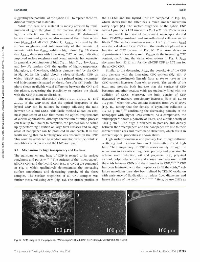
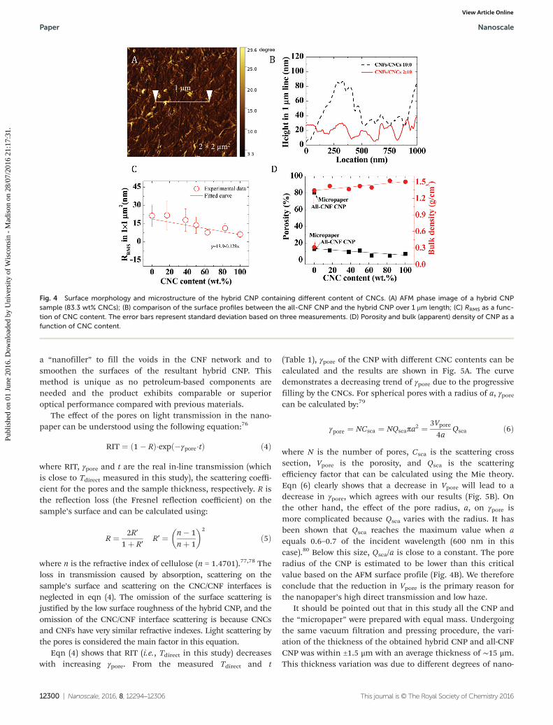
The transparency and haze of CNP is related to its surfaceroughness and porosity.70,71 The surfaces of the “micropaper”,all-CNF CNP and the hybrid CNP (83.3% CNCs) are comparedin Fig. 3, which qualitatively demonstrates the increasingsurface smoothness and decreasing porosity of the threesamples. The surface roughness of all CNP samples wasfurther measured using AFM (Fig. 4A). The surface profiles of
the all-CNF and the hybrid CNP are compared in Fig. 4B,which shows that the latter has a much smaller maximumvalley depth (Rv). The surface roughness of the hybrid CNPover a 1 µm line is 1.21 nm with a Rv of 4.71 nm. These valuesare comparable to those of transparent nanopaper derivedfrom TEMPO-preoxidized and microfluidized cellulose nano-fibrils.13 The surface roughness over a 1 × 1 µm2 area (RRMS)was also calculated for all CNP and the results are plotted as afunction of CNC content in Fig. 4C. The curve shows anapproximately linear decrease in RRMS with the increasing CNCcontent, confirming the visual observations in Fig. 3. RRMS
decreases from 22.11 nm for the all-CNF CNP to 5.75 nm forthe all-CNC CNP.
Similar to the decreasing RRMS, the porosity Φ of the CNPalso decrease with the increasing CNC content (Fig. 4D). Φdecreases approximately linearly from 13.3% to 7.5% as theCNC content increases from 0% to 100%. The trends of theRRMS and porosity both indicate that the surface of CNPbecomes smoother because voids are gradually filled with theaddition of CNCs. Moreover, the bulk density of CNPmeasured by mercury porosimetry increases from ca. 1.3 to1.5 g cm−3 when the CNC content increases from 0% to 100%(Fig. 4D, noting that the density of crystalline cellulose is1.5–1.6 g cm−3),72 confirming the decreasing porosity of thenanopaper with higher CNC content. As a comparison, the“micropaper” shows a porosity of 80.6% and a bulk density of∼0.3 g cm−3. The huge differences in porosity and densitybetween the “micropaper” and the nanopaper are due to theirdifferent fiber sizes and micro/nano structures, which result indifferent optical properties as shown above.
High surface roughness and porosity lead to high diffusivescattering and therefore low direct transmittance and highhaze. The transparency of CNP increases mainly through thereductions in its surface roughness, porosity and pore size. Toachieve such reduction, oil and polymers (e.g., polyvinylalcohol, polyethelyene oxide and epoxy) have been used to fillthe voids between CNFs and their bundles in CNP;53,73,74 CNPhas been laminated with thermoplastics to fill the voids;46 cel-lulose nanofibers have also been refined by TEMPO oxidationwith assistance of fluidization to reduce fiber diameters andhence the size of the voids.13,30,31,37,42,75 Here, we use CNCs as
Fig. 3 SEM images of the paper. (A) “Micropaper”; (B) all-CNF CNP; (C) hybrid CNP (83.3% CNCs).
Nanoscale Paper
This journal is © The Royal Society of Chemistry 2016 Nanoscale, 2016, 8, 12294–12306 | 12299
Publ
ishe
d on
01
June
201
6. D
ownl
oade
d by
Uni
vers
ity o
f W
isco
nsin
- M
adis
on o
n 28
/07/
2016
21:
17:3
1.
View Article Online
a “nanofiller” to fill the voids in the CNF network and tosmoothen the surfaces of the resultant hybrid CNP. Thismethod is unique as no petroleum-based components areneeded and the product exhibits comparable or superioroptical performance compared with previous materials.
The effect of the pores on light transmission in the nano-paper can be understood using the following equation:76
RIT ¼ ð1� RÞ�expð�γpore�tÞ ð4Þ
where RIT, γpore and t are the real in-line transmission (whichis close to Tdirect measured in this study), the scattering coeffi-cient for the pores and the sample thickness, respectively. R isthe reflection loss (the Fresnel reflection coefficient) on thesample’s surface and can be calculated using:
R ¼ 2R′1þ R′
R′ ¼ n� 1nþ 1
� �2
ð5Þ
where n is the refractive index of cellulose (n = 1.4701).77,78 Theloss in transmission caused by absorption, scattering on thesample’s surface and scattering on the CNC/CNF interfaces isneglected in eqn (4). The omission of the surface scattering isjustified by the low surface roughness of the hybrid CNP, and theomission of the CNC/CNF interface scattering is because CNCsand CNFs have very similar refractive indexes. Light scattering bythe pores is considered the main factor in this equation.
Eqn (4) shows that RIT (i.e., Tdirect in this study) decreaseswith increasing γpore. From the measured Tdirect and t
(Table 1), γpore of the CNP with different CNC contents can becalculated and the results are shown in Fig. 5A. The curvedemonstrates a decreasing trend of γpore due to the progressivefilling by the CNCs. For spherical pores with a radius of a, γporecan be calculated by:79
γpore ¼ NCsca ¼ NQscaπa2 ¼ 3Vpore4a
Qsca ð6Þ
where N is the number of pores, Csca is the scattering crosssection, Vpore is the porosity, and Qsca is the scatteringefficiency factor that can be calculated using the Mie theory.Eqn (6) clearly shows that a decrease in Vpore will lead to adecrease in γpore, which agrees with our results (Fig. 5B). Onthe other hand, the effect of the pore radius, a, on γpore ismore complicated because Qsca varies with the radius. It hasbeen shown that Qsca reaches the maximum value when aequals 0.6–0.7 of the incident wavelength (600 nm in thiscase).80 Below this size, Qsca/a is close to a constant. The poreradius of the CNP is estimated to be lower than this criticalvalue based on the AFM surface profile (Fig. 4B). We thereforeconclude that the reduction in Vpore is the primary reason forthe nanopaper’s high direct transmission and low haze.
It should be pointed out that in this study all the CNP andthe “micropaper” were prepared with equal mass. Undergoingthe same vacuum filtration and pressing procedure, the vari-ation of the thickness of the obtained hybrid CNP and all-CNFCNP was within ±1.5 μm with an average thickness of ∼15 μm.This thickness variation was due to different degrees of nano-
Fig. 4 Surface morphology and microstructure of the hybrid CNP containing different content of CNCs. (A) AFM phase image of a hybrid CNPsample (83.3 wt% CNCs); (B) comparison of the surface profiles between the all-CNF CNP and the hybrid CNP over 1 μm length; (C) RRMS as a func-tion of CNC content. The error bars represent standard deviation based on three measurements. (D) Porosity and bulk (apparent) density of CNP as afunction of CNC content.
Paper Nanoscale
12300 | Nanoscale, 2016, 8, 12294–12306 This journal is © The Royal Society of Chemistry 2016
Publ
ishe
d on
01
June
201
6. D
ownl
oade
d by
Uni
vers
ity o
f W
isco
nsin
- M
adis
on o
n 28
/07/
2016
21:
17:3
1.
View Article Online
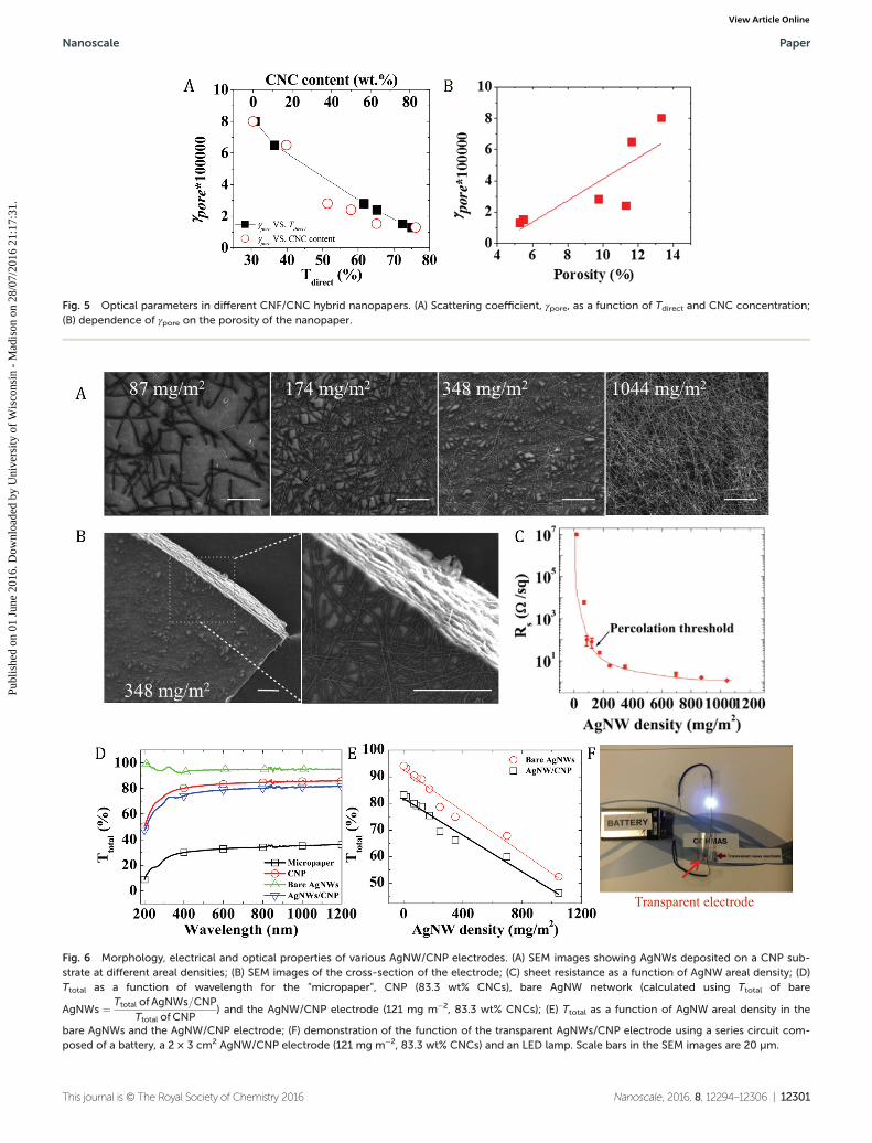
Fig. 5 Optical parameters in different CNF/CNC hybrid nanopapers. (A) Scattering coefficient, γpore, as a function of Tdirect and CNC concentration;(B) dependence of γpore on the porosity of the nanopaper.
Fig. 6 Morphology, electrical and optical properties of various AgNW/CNP electrodes. (A) SEM images showing AgNWs deposited on a CNP sub-strate at different areal densities; (B) SEM images of the cross-section of the electrode; (C) sheet resistance as a function of AgNW areal density; (D)Ttotal as a function of wavelength for the “micropaper”, CNP (83.3 wt% CNCs), bare AgNW network (calculated using Ttotal of bare
AgNWs ¼ Ttotal of AgNWs=CNP
Ttotal of CNP) and the AgNW/CNP electrode (121 mg m−2, 83.3 wt% CNCs); (E) Ttotal as a function of AgNW areal density in the
bare AgNWs and the AgNW/CNP electrode; (F) demonstration of the function of the transparent AgNWs/CNP electrode using a series circuit com-posed of a battery, a 2 × 3 cm2 AgNW/CNP electrode (121 mg m−2, 83.3 wt% CNCs) and an LED lamp. Scale bars in the SEM images are 20 µm.
Nanoscale Paper
This journal is © The Royal Society of Chemistry 2016 Nanoscale, 2016, 8, 12294–12306 | 12301
Publ
ishe
d on
01
June
201
6. D
ownl
oade
d by
Uni
vers
ity o
f W
isco
nsin
- M
adis
on o
n 28
/07/
2016
21:
17:3
1.
View Article Online
fiber packing between the samples (which resulted in differentporosities) and unevenness in thickness of each individualCNP. Therefore the porosity of CNP was a more accurate andreliable parameter than its thickness to be used in the discus-sion of the optical properties. The contribution of the thick-ness was also inherently taken into account through the use of
the porosity because these two parameters were related. As anexample, the thickness of the “micropaper” was about 10times that of the CNP because of its poor packing/high poro-sity, which led to its low optical properties.
3.3. Sheet resistance and transmittance of AgNW/CNP electrodes
The conductive AgNW network deposited on the CNP substrate(83.3% CNCs) is shown in Fig. 6A and B. The areal density ofthe nanowire network, defined as the weight of AgNWs perunit substrate area, increases from 87.0 to 1044.5 mg m−2,resulting in an increasingly dense AgNW network as shown inthe figure. The AgNWs have an average diameter of 74 nm andan average length of 37.5 µm, yielding an aspect ratio of 506.This high aspect ratio can lead to a percolated AgNW networkat a low areal density.81 As shown in Fig. 6C, the sheet resist-ance, Rs of the electrodes initially decreases rapidly withincreasing AgNW density and then stabilizes when the AgNWdensity is high, suggesting a percolation threshold of 121 mgm−2 (data in Table 2). The Rs values (1.16–23.48 Ω sq−1) for theAgNW/CNP electrodes with percolated AgNWs are lower thanor comparable to the value (16 Ω sq−1) for AgNW/glass electro-des with a transmittance of 86% reported in a prior study.82
Table 2 Electrical and optical properties of the bare AgNW networkand the AgNWs/CNP electrodes. Ttotal is sampled at 600 nm wavelength,Ttotal of the CNP substrate is 83.4%. The numbers in parenthesis arestandard deviations based on ten measurements
AgNW arealdensity(mg m−2)
Rs of AgNWs/CNP (Ω sq−1)
Ttotal of bareAgNWs (%)
Ttotal ofAgNWs/CNP(%)
1044 1.16 (0.07) 52.5 46.4696 2.33 (0.54) 67.9 60.0348 5.22 (0.82) 75.0 66.3243 5.82 (0.46) 78.7 70.0174 23.48 (2.57) 85.4 75.5121 75.48 (40.07) 89.2 78.887 104.33 (49.55) 89.6 79.269 6.33 (1.33) (kΩ sq−1) 90.5 80.017 10.23 (0.96) (MΩ sq−1) 93.4 82.5
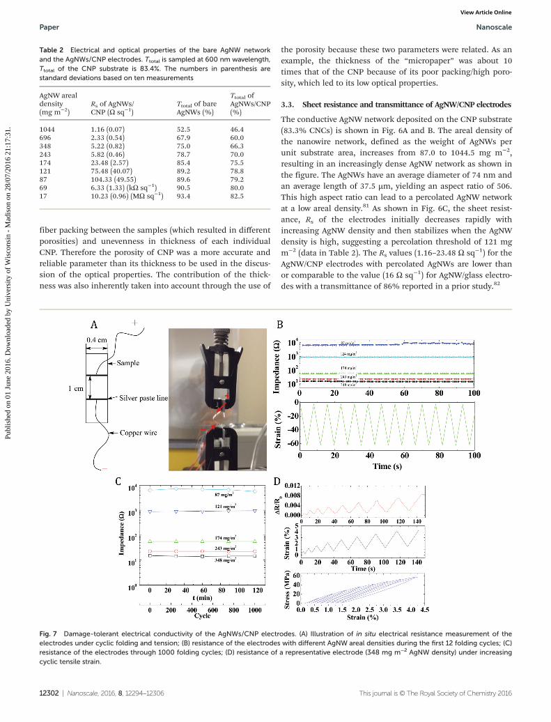
Fig. 7 Damage-tolerant electrical conductivity of the AgNWs/CNP electrodes. (A) Illustration of in situ electrical resistance measurement of theelectrodes under cyclic folding and tension; (B) resistance of the electrodes with different AgNW areal densities during the first 12 folding cycles; (C)resistance of the electrodes through 1000 folding cycles; (D) resistance of a representative electrode (348 mg m−2 AgNW density) under increasingcyclic tensile strain.
Paper Nanoscale
12302 | Nanoscale, 2016, 8, 12294–12306 This journal is © The Royal Society of Chemistry 2016
Publ
ishe
d on
01
June
201
6. D
ownl
oade
d by
Uni
vers
ity o
f W
isco
nsin
- M
adis
on o
n 28
/07/
2016
21:
17:3
1.
View Article Online
The total transmittance (Ttotal) of the AgNW/CNP electrodeis compared with that of a bare AgNW network (i.e. as an indi-vidual layer) in Fig. 6D and Table 2. The transmittance of theAgNW network can be calculated using the equation in Fig. 6after the transmittance of the CNP substrate and the bilayerelectrode are measured. The bare AgNW network is found tobe more transparent than the CNP. Depositing the highlytransparent AgNW network on the CNP substrate only slightlydecreases the Ttotal of the CNP. As a control, the Ttotal of the“micropaper” is much lower than those of the three samples.As expected, the transmittance decreases with increasingAgNW areal density in both the electrode and the AgNWnetwork (Fig. 6E). The fact that the two linear fitting lines inthe figure are parallel suggests that the decrease is primarilydue to the increasing AgNW areal density and the downshift ofthe top line (for the bare AgNWs) is caused by the CNP sub-strate. Fig. 6F demonstrates the high conductivity of theAgNW/CNP electrode by using it to connect a circuit and lightan LED.
3.4. Damage-tolerant electrical conductivity of AgNWs/CNPelectrodes
The electrical resistance of the electrode was monitored undercyclic folding between two grips (Fig. 7A). The folding actionwas performed by changing the distance between the grips,
and the degree of folding was quantified by a strain that isdefined as the ratio of the travel distance of one of the grips tothe initial gap distance between the two grips. Fig. 7B and Cshow the resistance of the electrodes with different AgNWareal densities under the cyclic strain. It is clear that the resist-ance decreases with increasing areal density and that theresistance remains nearly constant despite the folding action(Fig. 7B). All the samples maintain consistent resistance after1000 folding cycles (Fig. 7C). These results demonstrate therobustness of the electrodes under the folding action, whichcan be attributed to the strong adhesion between the AgNWnetwork and the CNP substrate and between the individualAgNWs at their junctions.
The resistance of the electrode was also measured while thesample was under increasing cyclic tensile strain (until thesample fractured at ∼4% strain). A comparison of the resistanceand the strain curves in Fig. 7D shows that the former traces thelatter, suggesting a linear relationship between the strain andthe resistance change. When a tensile strain is exerted on theelectrode, the nanowires can elongate and/or some connectionsbetween the nanowires can be broken, both of which increasethe resistance. However, the reversibility of the resistance undercyclic strain indicates that the deformation/breakage is transi-ent. The linear strain-resistance relationship suggests the elec-trode’s potential as a strain sensor.6,83,84
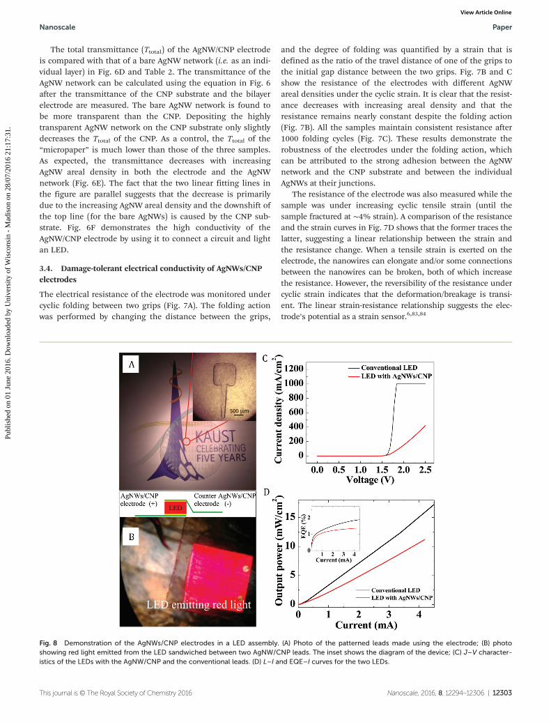
Fig. 8 Demonstration of the AgNWs/CNP electrodes in a LED assembly. (A) Photo of the patterned leads made using the electrode; (B) photoshowing red light emitted from the LED sandwiched between two AgNW/CNP leads. The inset shows the diagram of the device; (C) J–V character-istics of the LEDs with the AgNW/CNP and the conventional leads. (D) L–I and EQE–I curves for the two LEDs.
Nanoscale Paper
This journal is © The Royal Society of Chemistry 2016 Nanoscale, 2016, 8, 12294–12306 | 12303
Publ
ishe
d on
01
June
201
6. D
ownl
oade
d by
Uni
vers
ity o
f W
isco
nsin
- M
adis
on o
n 28
/07/
2016
21:
17:3
1.
View Article Online
3.5. AgNWs/CNP electrodes for LED devices
The transparent AgNW/CNP electrodes developed in this studycan be used to build flexible display devices. As a first demon-stration, we produced “screw”-like, micro-sized AgNW/CNPleads formed by patterning the AgNW layer on a CNP substratecontaining 83.3 wt% CNCs (Fig. 8A). We then sandwiched anAlGaInP-based red LED microchip between two of the trans-parent leads (Fig. 8C inset). Red light was emitted when adirect-current (DC) voltage was applied on the two leads(Fig. 8B). The current density–voltage ( J–V) characteristic of thedevice was measured and compared with that of a LED deviceusing conventional Ti/Au metallic leads (Fig. 8C). The com-parison indicates that the turn-on voltage of the LED with theAgNW/CNP leads is similar to that of the conventional lead.The lower current density for the AgNW/CNP leads may be dueto the contact resistance at the AgNW junctions, which isexpected to be reduced using methods such as localizedannealing. Fig. 8D shows the light output power–current (L–I)and external quantum efficiency–current (EQE–I) relations ofour and the conventional LEDs. Both the output power andEQE of our LED are moderately lower than those of the conven-tional LED, likely due to its higher contact resistance. Never-theless, using AgNW/CNP as transparent electrodes in LEDs isfeasible. Multiple light emitting devices can be packed on thepatterned AgNW/CNP electrodes and flexible display devicescan then be produced. This demonstration paves the way forfurther development of flexible displays based on our facilenanopaper fabrication technology.
4. Conclusion and outlook
In this study, we developed a facile methodology to synthesizehighly transparent, mechanically robust, hybrid CNP consist-ing of CNFs and CNCs. In this CNP, CNFs form an entanglednetwork to impart the nanopaper strength and flexibility;CNCs act as a rigid nanofiller to modify its structure and pro-perties. Optical properties of the nanopaper can be tailored byvarying the ratio between CNFs and CNCs. The concentrationof CNCs affects the surface roughness, porosity and CNFentanglement of the nanopaper, resulting in varied opticalproperties. Our hybrid CNP has equivalent or higher totaltransmittance and much smaller haze compared with the all-CNF CNP reported in the literature. This is due to the lowsurface roughness and porosity of the hybrid CNP that are ren-dered by the “filling” effect of CNCs. Depositing AgNWs on ahybrid CNP substrate produces transparent, flexible electrodes,whose conductivity is dependent on the areal density ofAgNWs. In situ measurement of the conductivity during cyclicloading shows that the electrical property of the electrode istolerant to damage under folding deformation. Under tensiledeformation, the electrical resistance of the electrode exhibitsa linear relationship with the tensile strain, suggesting itspotential to be used as a strain sensor. A proof-of-concept LEDdevice has been created to demonstrate the nanopaper electro-de’s potential use in flexible electronic devices. Further work
to decrease the contact resistance of the electrode for use inlarge area flexible displays will be conducted.
We have achieved a high direct transmittance of 75.1% anda low haze of 10.0% in our nanopaper. With ongoing intensivestudies on nanopaper, these values will almost certainly besurpassed in the future. These values, however, indicate thatnanopaper can already be used in flexible devices to replacetraditional plastics (e.g., PET). Even more importantly, we havedemonstrated a facile method that produces nanopaper with awide range of optical and electrical properties, which shouldmake production of the material appealing.
Due to the hydrophilic nature of cellulose, ensuring thestructural integrity and performance stability of the CNP-basedelectrodes in humid environment can be challenging. Onesolution is to develop hydrophobic or even superhydrophobicCNP by surface engineering of the CNP (e.g. creating a hier-archical surface structure and applying hydrophobic nano-particles on the surface at the same time). Through the tensiletests we have also found that the tensile properties of thehybrid CNP strongly depends on the CNF/CNC ratio. This isunderstandable because CNCs and CNFs exhibit differentmechanical properties and the structure (e.g. porosity) of theCNP varies with the ratio. While the CNP generally showed alow strain-at-failure under tension, it was quite flexible anddamage-tolerant as demonstrated by the folding tests. Thefocus of this study is on optical and electrical properties of thenanopaper, which are critical to the performance of flexibledisplays. The results about its mechanical properties will bereported in a future publication.
Acknowledgements
Financial supports from North Dakota EPSCoR, KAUST Base-line, and a USDA Agriculture and Food Research Initiative(AFRI) Competitive Grant (no. 2011-67009-20056) are greatlyappreciated.
References
1 A. R. Madaria, A. Kumar and C. Zhou, Nanotechnology,2011, 22, 245201.
2 S. Reineke, F. Lindner, G. Schwartz, N. Seidler, K. Walzer,B. Lüssem and K. Leo, Nature, 2009, 459, 234–238.
3 D.-S. Leem, A. Edwards, M. Faist, J. Nelson,D. D. C. Bradley and J. C. de Mello, Adv. Mater., 2011, 23,4371–4375.
4 M. Nasr Saleh and G. Lubineau, Sol. Energy Mater. Sol.Cells, 2014, 130, 199–207.
5 J. Zhou and G. Lubineau, ACS Appl. Mater. Interfaces, 2013,5, 6189–6200.
6 J. Zhou, T. Fukawa, H. Shirai and M. Kimura, Macromol.Mater. Eng., 2010, 295, 671–675.
7 L. Hu, H. S. Kim, J. Lee, P. Peumans and Y. Cui, ACS Nano,2010, 4, 2955–2963.
Paper Nanoscale
12304 | Nanoscale, 2016, 8, 12294–12306 This journal is © The Royal Society of Chemistry 2016
Publ
ishe
d on
01
June
201
6. D
ownl
oade
d by
Uni
vers
ity o
f W
isco
nsin
- M
adis
on o
n 28
/07/
2016
21:
17:3
1.
View Article Online
8 S. De, T. M. Higgins, P. E. Lyons, E. M. Doherty,P. N. Nirmalraj, W. J. Blau, J. J. Boland and J. N. Coleman,ACS Nano, 2009, 3, 1767–1774.
9 X.-Y. Zeng, Q.-K. Zhang, R.-M. Yu and C.-Z. Lu, Adv. Mater.,2010, 22, 4484–4488.
10 J. Liang, L. Li, K. Tong, Z. Ren, W. Hu, X. Niu, Y. Chen andQ. Pei, ACS Nano, 2014, 8, 1590–1600.
11 L. Hu, G. Zheng, J. Yao, N. Liu, B. Weil, M. Eskilsson,E. Karabulut, Z. Ruan, S. Fan, J. T. Bloking,M. D. McGehee, L. Wågberg and Y. Cui, Energy Environ.Sci., 2013, 6, 513.
12 F. Cherubini, Energy Convers. Manage., 2010, 51, 1412–1421.
13 J. Huang, H. Zhu, Y. Chen, C. Preston, K. Rohrbach,J. Cumings and L. Hu, ACS Nano, 2013, 7, 2106–2113.
14 Q. Q. Wang, J. Y. Zhu, R. Gleisner, T. A. Kuster, U. Baxa andS. E. McNeil, Cellulose, 2012, 19, 1631–1643.
15 J. Y. Zhu, R. Sabo and X. Luo, Green Chem., 2011, 13, 1339.16 M. Henriksson, L. A. Berglund, P. Isaksson and T. Lindstro,
Biomacromolecules, 2008, 9, 1579–1585.17 W. Wang, M. D. Mozuch, R. C. Sabo, P. Kersten, J. Y. Zhu
and Y. Jin, Cellulose, 2015, 22, 351–361.18 H. Fukuzumi, T. Saito, T. Iwata, Y. Kumamoto and
A. Isogai, Biomacromolecules, 2009, 10, 162–165.19 L. Wgberg, G. Decher, M. Norgren, T. Lindström,
M. Ankerfors, K. Axnäs, L. Wagberg, G. Decher,M. Norgren, T. Lindstrom, M. Ankerfors and K. Axnas,Langmuir, 2008, 24, 784–795.
20 Q. Wang, J. Y. Zhu and J. M. Considine, ACS Appl. Mater.Interfaces, 2013, 5, 2527–2534.
21 L. Chen, Q. Wang, K. Hirth, C. Baez, U. P. Agarwal andJ. Y. Zhu, Cellulose, 2015, 1753–1762.
22 M. Jonoobi, R. Oladi, Y. Davoudpour, K. Oksman,A. Dufresne, Y. Hamzeh and R. Davoodi, Cellulose, 2015,22, 935–969.
23 H. P. S. Abdul Khalil, Y. Davoudpour, M. N. Islam,A. Mustapha, K. Sudesh, R. Dungani and M. Jawaid, Carbo-hydr. Polym., 2014, 99, 649–665.
24 L. Chen, J. Y. Zhu, C. Baez, P. Kitin and T. Elder, GreenChem., 2016, DOI: 10.1039/c6gc00687f.
25 M. S. Peresin, Y. Habibi, J. O. Zoppe, J. J. Pawlak andO. J. Rojas, Biomacromolecules, 2010, 11, 674–681.
26 A. N. Nakagaito and H. Yano, Cellulose, 2008, 15, 555–559.
27 M. S. Wang, F. Jiang, Y.-L. Hsieh and N. Nitin, J. Mater.Chem. B, 2014, 2, 6226.
28 X. Xu, J. Zhou, D. H. Nagaraju, L. Jiang, V. R. Marinov,G. Lubineau, H. N. Alshareef and M. Oh, Adv. Funct. Mater.,2015, 25, 3193–3202.
29 H. Sehaqui, A. Liu, Q. Zhou and L. a. Berglund, Biomacro-molecules, 2010, 11, 2195–2198.
30 H. Zhu, S. Parvinian, C. Preston, O. Vaaland, Z. Ruan andL. Hu, Nanoscale, 2013, 5, 3787–3792.
31 Z. Fang, H. Zhu, Y. Yuan, D. Ha, S. Zhu, C. Preston,Q. Chen, Y. Li, X. Han, S. Lee, G. Chen, T. Li, J. Munday,J. Huang and L. Hu, Nano Lett., 2014, 14, 765–773.
32 H. Sehaqui, N. E. Mushi, S. Morimune, M. Salajkova,T. Nishino and L. A. Berglund, ACS Appl. Mater. Interfaces,2012, 4, 1043–1049.
33 A. Walther, J. V. I. Timonen, I. Díez, A. Laukkanen andO. Ikkala, Adv. Mater., 2011, 23, 2924–2928.
34 S. J. Eichhorn, A. Dufresne, M. Aranguren, N. E. Marcovich,J. R. Capadona, S. J. Rowan, C. Weder, W. Thielemans,M. Roman, S. Renneckar, W. Gindl, S. Veigel, J. Keckes,H. Yano, K. Abe, M. Nogi, A. N. Nakagaito, A. Mangalam,J. Simonsen, A. S. Benight, A. Bismarck, L. a. Berglund andT. Peijs, J. Mater. Sci., 2009, 45, 1–33.
35 Z. Fang, H. Zhu, C. Preston, X. Han, Y. Li, S. Lee, X. Chai,G. Chen and L. Hu, J. Mater. Chem. C, 2013, 1, 6191.
36 H. Tang, N. Butchosa and Q. Zhou, Adv. Mater., 2015, 27,2070–2076.
37 H. Yano, J. Sugiyama, A. N. Nakagaito, M. Nogi,T. Matsuura, M. Hikita and K. Handa, Adv. Mater., 2005,17, 153–155.
38 S. C. M. Fernandes, L. Oliveira, C. S. R. Freire,A. J. D. Silvestre, C. P. Neto, A. Gandini and J. Desbriéres,Green Chem., 2009, 11, 2023.
39 S. Iwamoto, A. N. Nakagaito, H. Yano and M. Nogi, Appl.Phys. A, 2005, 81, 1109–1112.
40 X. Sun, Q. Wu, S. Ren and T. Lei, Cellulose, 2015, 22, 1123–1133.
41 M.-C. Hsieh, C. Kim, M. Nogi and K. Suganuma, Nanoscale,2013, 5, 9289–9295.
42 Z. Fang, H. Zhu, W. Bao, C. Preston, Z. Liu, J. Dai, Y. Li andL. Hu, Energy Environ. Sci., 2014, 7, 3313–3319.
43 H. Zhu, Z. Fang, C. Preston, Y. Li and L. Hu, EnergyEnviron. Sci., 2014, 7, 269–287.
44 M. Nogi, N. Komoda, K. Otsuka and K. Suganuma, Nano-scale, 2013, 5, 4395–4399.
45 M. Nogi and H. Yano, Adv. Mater., 2008, 20, 1849–1852.46 M. Nogi, S. Iwamoto, A. N. Nakagaito and H. Yano, Adv.
Mater., 2009, 21, 1595–1598.47 H. Koga, M. Nogi, N. Komoda, T. T. Nge, T. Sugahara and
K. Suganuma, NPG Asia Mater., 2014, 6, e93.48 H. Zhu, Z. Xiao, D. Liu, Y. Li, N. J. Weadock, Z. Fang,
J. Huang and L. Hu, Energy Environ. Sci., 2013, 6, 2105.49 A. Isogai, T. Saito and H. Fukuzumi, Nanoscale, 2011, 3, 71–
85.50 C. Preston, Z. Fang, J. Murray, H. Zhu, J. Dai, J. N. Munday
and L. Hu, J. Mater. Chem. C, 2014, 2, 1248.51 H. Sehaqui, Q. Zhou, O. Ikkala and L. A. Berglund, Bio-
macromolecules, 2011, 12, 3638–3644.52 Q. Q. Wang, J. Y. Zhu, R. S. Reiner, S. P. Verrill, U. Baxa and
S. E. McNeil, Cellulose, 2012, 19, 2033–2047.53 X. Xu, F. Liu, L. Jiang and J. Zhu, ACS Appl. Mater. Inter-
faces, 2013, 5, 2999–3009.54 X. Xu, H. Wang, L. Jiang, X. Wang, S. a. Payne, J. Y. Zhu
and R. Li, Macromolecules, 2014, 47, 3409–3416.55 A. Liu, A. Walther, O. Ikkala, L. Belova and L. a. Berglund,
Biomacromolecules, 2011, 12, 633–641.56 H. Yu, Z. Qin, B. Liang, N. Liu, Z. Zhou and L. Chen,
J. Mater. Chem. A, 2013, 1, 3938.
Nanoscale Paper
This journal is © The Royal Society of Chemistry 2016 Nanoscale, 2016, 8, 12294–12306 | 12305
Publ
ishe
d on
01
June
201
6. D
ownl
oade
d by
Uni
vers
ity o
f W
isco
nsin
- M
adis
on o
n 28
/07/
2016
21:
17:3
1.
View Article Online
57 T. Kunugi, C. Ichinose and A. Suzuki, J. Appl. Polym. Sci.,1986, 31, 429–439.
58 D. Y. Choi, H. W. Kang, H. J. Sung and S. S. Kim, Nanoscale,2013, 5, 977–983.
59 HunterLab, 2008, http://barnett-technical.com/HunterLab%20Haze%20Ap.
60 D. Corning, 2015, https://www.dowcorning.com/content/publishedlit/11.
61 C. Wan, X. Qiao, Y. Zhang and Y. Zhang, Polym. Test., 2003,22, 453–461.
62 J. Krč, M. Zeman, F. Smole and M. Topič, J. Appl. Phys.,2002, 92, 749.
63 K. Resch, Polym. Eng. Sci., 2006, 521–531.64 R. Zhou and T. Burkhart, J. Appl. Polym. Sci., 2010, 115,
1866–1872.65 T. Wydeven, Appl. Opt., 1977, 16, 717–721.66 Q. G. Gu and Q. L. Zhou, Eur. Polym. J., 1998, 34, 1727–
1733.67 B. M. R. Galdi, V. Nicolais, L. Di Maio and L. Incarnato,
Packag. Technol. Sci., 2008, 21, 257–268.68 R. S. Jagadish and B. Raj, Food Hydrocolloids, 2011, 25,
1572–1580.69 J. Zhang, W. Tu and Z. Dai, Prog. Org. Coat., 2012, 75, 579–
583.70 A. Hongsingthong, T. Krajangsang, I. A. Yunaz, S. Miyajima
and M. Konagai, Appl. Phys. Express, 2010, 3, 051102.
71 J. P. Chem, F. C. Stehling, C. S. Speed and L. Westerman,Macromolecules, 1981, 14, 698–708.
72 A. Dufresne, Mater. Today, 2013, 16, 220–227.73 J. Wang, Q. Cheng, L. Lin and L. Jiang, ACS Nano, 2014,
2739–2745.74 Y. Okahisa, A. Yoshida, S. Miyaguchi and H. Yano, Compos.
Sci. Technol., 2009, 69, 1958–1961.75 H.-W. Liang, Q.-F. Guan, Z. Zhu, L.-T. Song, H.-B. Yao,
X. Lei and S.-H. Yu, NPG Asia Mater., 2012, 4, e19.76 R. Apetz and M. P. B. Van Bruggen, J. Am. Ceram. Soc.,
2003, 86, 480–486.77 N. Sultanova, S. Kasarova and I. Nikolov, Acta Phys. Pol., A,
2009, 116, 585–587.78 N. Sultanova and S. Kasarova, Refract. website, 2016, http://
refractiveindex.info/?shelf=organic&book=ce.79 R. Boulesteix, A. Maître, L. Chrétien, Y. Rabinovitch and
C. Sallé, J. Am. Ceram. Soc., 2013, 96, 1724–1731.80 W. Zhang, T. Lu, N. Wei, Y. Wang, B. Ma, F. Li, Z. Lu and
J. Qi, J. Alloys Compd., 2012, 520, 36–41.81 S. Ye, A. R. Rathmell, Z. Chen, I. E. Stewart and B. J. Wiley,
Adv. Mater., 2014, 26, 6670–6687.82 J. Lee, S. T. Connor, Y. Cui and P. Peumans, Nano Lett.,
2008, 8, 689–692.83 J. Zhou, SEN’I GAKKAISHI, 2011, 67, 125–131.84 J. Zhou, T. Fukawa and M. Kimura, Polym. J., 2011, 43, 849–
854.
Paper Nanoscale
12306 | Nanoscale, 2016, 8, 12294–12306 This journal is © The Royal Society of Chemistry 2016
Publ
ishe
d on
01
June
201
6. D
ownl
oade
d by
Uni
vers
ity o
f W
isco
nsin
- M
adis
on o
n 28
/07/
2016
21:
17:3
1.
View Article Online