Embed Size (px)
Citation preview

Hm
XGa
b
c
ARRA
KUPSH
1
fibctmp
lw[pmi
g
0h
Synthetic Metals 175 (2013) 138– 145
Contents lists available at SciVerse ScienceDirect
Synthetic Metals
journa l h om epa ge: www.elsev ier .com/ locate /synmet
ighly stable polypyrrole film prepared by unipolar pulse electro-polymerizationethod as electrode for electrochemical supercapacitor
iao Dua, Xiaogang Haoa,∗, Zhongde Wanga, Xuli Maa, Guoqing Guanb,∗∗, Abudula Abuliti b,uozhang Mac, Shibin Liua
Department of Chemical Engineering, Taiyuan University of Technology, Taiyuan 030024, ChinaNorth Japan Research Institute for Sustainable Energy (NJRISE), Hirosaki University, 2-1-3, Matsubara, Aomori 030-0813, JapanShanxi Institute of Applied Chemistry, Taiyuan 030024, China
a r t i c l e i n f o
rticle history:eceived 8 February 2013eceived in revised form 5 May 2013ccepted 8 May 2013
eywords:nipolar pulse electro-polymerizationolypyrrole filmupercapacitor
a b s t r a c t
Polypyrrole (PPy) film was fabricated on platinum substrate by a facile unipolar pulse electro-polymerization (UPEP) method. Mechanism for the formation of highly stable PPy film was proposedbased on the chronoamperogram obtained during the polymerization process. Structure, surface mor-phology and hydrophilic property of the PPy film prepared using either UPEP method or potentiostaticmethod (PM) were characterized by Fourier transfer infrared spectroscopy (FT-IR), scanning electronmicroscopy (SEM) and contact angle goniometer, respectively. Electrochemical performances of PPy filmsprepared by UPEP and PM were compared using cyclic voltammetry (CV), galvanostatic charge/dischargetests and electrochemical impedance spectroscopy (EIS) in 1.0 M of KCl solution. It is found that the PPy
igh cycle stability film prepared by UPEP method under the conditions of ultra short on-time pulse (10 ms) and low tem-perature (10.0 ◦C) showed an ordered structure with reduced chain defects and exhibited high specificcapacitance and excellent cycling stability in neutral solution. The capacitance of such a PPy film electroderetained 93.6% of its initial value even after 50,000 charge/discharge cycles. The specific capacitance ofthe UPEP PPy film reached 406.0 F g−1 at a scan rate of 5 mV s−1 when temperature, pulse potential, pulsetime ratio (t /t ) and pulse cycles were 10.0 ◦C, 0.7 V, 10 ms/100 ms and 12,000, respectively.
on off. Introduction
Conducting polymer (CP) has attracted considerable attentionor the development of electrochemical capacitor (EC) because ofts high electrochemical activity, remarkable environmental sta-ility and low cost [1–3]. Among the CPs, polypyrrole (PPy) wasonsidered a particularly appropriate electrode material for EC dueo its better electrochemical activity in neutral (pH ∼ 7) aqueous
edia and lower carcinogenic risk associated with its degradationroduct [4,5].
However, similar to other CPs, PPy showed instability afterong-term cyclical usage because the redox sites in its backbone
ere not sufficiently stable during the repeated redox processes6,7]. Recently, several strategies, such as compositing PPy with
orous carbon materials [8,9] and doping of various ions in itsicrostructure [10,11], were applied to improve the electrochem-cal performance of PPy-based supercapacitor. It is found that
∗ Corresponding author. Tel.: +86 351 6018193; fax: +86 351 6018554.∗∗ Corresponding author. Tel.: +81 17 762 7756; fax: +81 17 735 5411.
E-mail addresses: [email protected], [email protected] (X. Hao),[email protected] (G. Guan).
379-6779/$ – see front matter © 2013 Elsevier B.V. All rights reserved.ttp://dx.doi.org/10.1016/j.synthmet.2013.05.013
© 2013 Elsevier B.V. All rights reserved.
the surface morphology and the intrinsic capacitive property ofPPy material were significantly depended on the polymerizationmethod and synthesis condition [12–15]. Generally, PPy film canbe synthesized either by chemical method or by electrochemicalpolymerization [16,17]. In comparison with the chemical method,the electrochemical polymerization method, such as galvanostatic[18], potentiostatic [19] or cyclic voltammetric [20,21] polymer-ization, was considered as a simpler and more attractive techniqueto obtain the PPy film adhered well on the anode. Furthermore,the film thickness could be tuned by controlling the total chargepassed during the deposition process. Recently, pulse potentio-static method (PPM) [22–26] and pulse galvanostatic method(PGM) [27–30] were developed. The PPy film fabricated by PPMwas found to have better electrical conductivity and more excellentlevel of molecular anisotropy [23]. Furthermore, its surface becamesmoother due to the application of the pulse mode. However, a partof the electrical input was simultaneously consumed for the reduc-tion of PPy, resulting in lower coulombic efficiency. When the PPyfilm was fabricated on porous carbon materials, such as graphene
[25] and carbon nanotube network [26], and applied for the super-capacitor by PPM, higher specific capacitance and higher energydensity were obtained owing to the higher specific surface area ofthe conductive matrix. On the other hand, the PPy film prepared
etals
bsrocp
mdtpecfificsciutPpcc
2
2
awt
2
fitchas
(scceaop(fseawenfmtH
X. Du et al. / Synthetic M
y PGM was found to have lower defect density in the polymertructure and higher doping degree with excellent electrochemicaleversibility [28]. However, the corresponding oxidation potentialf the film was found to be changed with time, and the PPy filmould be over-oxidized at the higher pulse peak current during theolymerization process.
In our previous studies, a unipolar pulse electro-depositionethod, which combines the advantages of PPM and PGM, was
eveloped for the preparation of organic and inorganic composi-ed electroactive materials [31–33]. In this technique, an on-timeeriod, in which a potential is fixed and current can be gen-rated, is applied, followed by an off-time period, in which nourrent is allowed to flow. Using this method, inorganic NiHCFlm with controllable structure [31], nanorod polyaniline (PANI)lm [32] and NiHCF/CS/CNTs composite film with high electro-atalytic activity were successfully fabricated [33]. In the presenttudy, the PPy film with high specific capacitance and excellentycling stability in neutral solution was also prepared on plat-num substrate using this unipolar pulse method; here we called itnipolar pulse electro-polymerization (UPEP) method. Microstruc-ure, hydrophilic property and electrochemical performance of thePy film were characterized and compared with those films pre-ared by potentiostatic method (PM). In order to investigate theycling stability of the film in neutral solution, 50,000 cycles ofharge/discharge were performed.
. Experimental
.1. Materials
Pyrrole (Sigma–Aldrich) was distilled under reduced pressurend stored in nitrogen atmosphere prior to use. Other chemicalsere reagent grade and used without further purification. All solu-
ions were prepared using ultra pure water (Millipore 18.2 M� cm).
.2. Electrode preparation
Electrochemical preparation and characterization of the PPylm were performed using a three-electrode system in conjunc-ion with a VMP3 Potentiostat (Princeton, USA) operated with aomputer interface using a software EC-Lab for control and dataandling. Two platinum sheets were served as working electrodend auxiliary electrode, respectively. Reference electrode was aaturated calomel electrode (SCE).
Prior to the polymerization, the platinum sheet10.0 mm × 10.0 mm × 0.2 mm) was polished into a mirror-likeurface with 0.5 �m alumina slurry on microcloth pads, and thenleaned electrochemically in 1.0 M of H2SO4 by 50 voltammetryycles from −0.275 to 1.675 V at 0.05 V s−1. The platinum workinglectrode with 0.5 cm2 of effective surface area was created using
PVC tape mask adhered to one side of the sheet. The other sidef the electrode was covered by a PVC tape. Two electrochemicalrocedures, i.e., the UPEP method and the potentiostatic methodPM) were employed. The first procedure was performed asollows: two Pt sheets were immersed vertically in an aqueousolution containing 0.1 M Py + 0.1 M HCl + 0.4 M KCl. The wholelectrochemical cell was immersed in a bath at a constant temper-ture of 10.0 ◦C. Each pulse consisted of an on-time (ton = 10 ms)hen an oxidizing voltage (0.7 V) was applied on the working
lectrode to generate a current and an off-time (toff = 100 ms) wheno current was allowed to flow. The number of pulse cycles to
abricate the film was 12,000. After UPEP PPy film was formed, theodified electrode was washed with water/ethanol solution and
hen immersed vertically in a new aqueous solution with 0.1 MCl + 0.4 M KCl but without pyrrole, and the background charging
175 (2013) 138– 145 139
current caused by the electrochemical double layers was measuredby applying the same pulse potential in this solution system. In thesecond procedure (PM), a constant voltage (0.7 V) was applied tothe working electrode, where the same solution as that in the UPEPmethod was used. However, the electro-polymerization time wasset at 6 min so that the total charge used for pyrrole polymerizationwas the same as that in the UPEP method for comparison. All filmswere washed completely with water/ethanol solution and dried ina nitrogen atmosphere at room temperature.
2.3. Characterization and measurements
Fourier transfer infrared spectroscopy (FT-IR) spectrum in KBrpellet was recorded on an IRAffinity-1 workstation (Shimadzu,Japan). Morphology of the film was examined by a scanning elec-tron microscope (SEM, LEO438VP, USA). The contact angle of wateron the film was measured by a contact angle goniometer (SL200B,USA). The electronic conductivity of the PPy film peeled from theplatinum electrode was measured by using four-point probe meter(RTS-9, China).
Electrochemical performance of the film was investigated bycyclic voltammeter (CV) and electrochemical impedance spec-troscopy (EIS) techniques in the three-electrode system. Afterelectro-polymerization, the PPy film was transferred into anotherelectrochemical cell containing 1.0 M of KCl. Electroactivity andspecific capacitance were investigated by CV from −0.8 to 0.5 Vat various scan rates. EIS measurement was carried out with fre-quencies varying from 100 kHz to 10 Hz, using AC amplitude of10 mV at open circuit potentials. A symmetrical two-electrode sys-tem was assembled with two symmetrical 0.5 cm2 PPy electrodesfor galvanostatic charge/discharge measurement at different cur-rent densities and long term cycle stability test, and the distancebetween the two electrodes was kept at 1.0 mm.
3. Results and discussion
3.1. Electro-polymerization process of PPy films
The optimum operation parameters for the electrochemicalpolymerization of PPy employing UPEP method was found tobe 0.7 V, on-time of 10 ms and off-time of 100 ms over 12,000cycles. Fig. 1A and B shows the first 0.3 s and the last 0.6 s cur-rent density/potential-time transient curves respectively duringthe pulse polymerization process for the fabrication of PPy film.As shown in Fig. 1A, the initial open circuit potential (OCP) on theworking electrode was approximately 0.35 V and no current flowedthrough the working electrode at the start of the process prior to theelectro-polymerization of PPy film. During the pulse polymeriza-tion process, the potential on the working electrode automaticallydecayed during the off-time period and increased periodically fromOCP to 0.7 V during the on-time period. The oxidation state of thesynthesized PPy film could be maintained at toff since the OCP onthe working electrode was over 0.54 V throughout the polymeriza-tion process. During a relatively long off-time, the reactants couldbe adequately replenished on the surface of the electrode via diffu-sion. With the application of potential during the on-time period,there was a rapid increase in current which then rapidly decayedto a lower stable value. The initial current spike should be mainlyattributed to the charging current of the electrochemical doublelayers, and subsequently, the relatively lower steady current shouldbe attributed to the Faradaic current from the oxidation of pyrrole
monomer. The relatively shorter pulse on-time of 10 ms and lowerreaction temperature were expected to reduce the defect densityof PPy films, which will be discussed in Section 3.2.2. As shown inFig. 1B, the change of current density at each pulse on time was
140 X. Du et al. / Synthetic Metals
Fig. 1. Current density/potential-time transients of the initial 0.3 s (A) and the last0.6 s (B) during UPEP of PPy film from 0.1 M pyrrole, 0.1 M HCl and 0.4 M KCl mixedsolution, (C) the curves of initial (a) and terminative (b) peak current densities ofevery pulse on-time versus time during pulse deposition of PPy. Pulse conditions:0T
st
ccitwctaiWtmc
bending vibration respectively [34]; the symmetric and asymmet-
.7 V pulse potential, 10 ms on-time and 100 ms off-time, 12,000 pulse numbers.he inset is an enlargement of the initial 150 s of the current density–time curves.
imilar, indicating that pyrrole could be formed on the surface ofhe electrode uniformly.
Fig. 1C shows the profiles of initial (a) and terminal (b) transienturrent densities of every ton during UPEP of PPy. From curve (b), itan be seen that the current density, which indicated the polymer-zation rate of PPy, increased gradually within the initial 150 s andhen reached a plateau. This was because the PPy polymerizationas a self-catalytic reaction process and the initially generated PPy
ould accelerate the subsequent PPy generation reactions duringhe initial 150 s. In addition, the increase of the electrode surfacerea for electro-polymerization of PPy also played a critical rolen the increase of the current density in this polymerization stage.
hen the current density increased to 5 mA cm−2, the polymeriza-
ion rate of PPy could be controlled by the diffusion rate of pyrroleonomer from solution to the electrode surface. In contrast, theurrent density depicted by curve (a) decreased rapidly in the initial
175 (2013) 138– 145
2 s, and then increased gradually in the following period of 2–20 sand finally declined again during the last 20–150 s. At the initialstage of electro-polymerization of PPy, the pyrrole monomer atthe electrode surface was oxidized to the delocalized monomericradicals followed by aromatization and oxidation of the dimer andoligomer [12]. However, most oligomeric radicals could not be con-verted into polymer chains in the initial stage of the polymerizationprocess due to the ultra short on-time pulse. Therefore, the forma-tion of a large number of radical cations could result in high electricdouble layer capacitance and hence the increase in current densityas indicated in curve (a). With further coupling reactions of theoligomeric radicals on the electrode surface, the formation of thePPy chain also proceeded, resulting in the charging peak currentdeclining gradually. In such an electro-polymerization process, anyoligomeric radical should have an equal opportunity to nucleateon the fresh sites of the electrode due to the continuous electri-cal pulse stimulation, which is beneficial for improving the level ofmolecular anisotropy and the uniformity of PPy morphology. After150 s of polymerization, the current density indicated by curve (a)remained almost constant. In this process, the pyrrole should bepolymerized on the surface of the PPy film by one dimensionalgrowth along the potential field towards the auxiliary electrode.In this case, some structural irregularities or defects such as branchpoints, cross links and conformational defects could be effectivelyrestrained.
3.2. Morphology and molecular structure of the PPy film
3.2.1. SEM imageSurface morphologies of UPEP PPy and PM PPy films are shown
in Fig. 2. Both films exhibited typical cauliflower-like morphol-ogy structure. However, it is obvious that the PPy film preparedby UPEP method exhibited more homogeneous particle distribu-tion when compared with the film prepared by PM method. Inthe case of UPEP method, the pyrrole monomers on the surfaceof the platinum sheet were oxidized to radical cations and sub-sequently coupled to form PPy nanoparticles during the on-timepulse period. In the following off-time pulse, the growth of PPynanoparticles could be frustrated, and the relatively long off-time(100 ms) could enhance the already grown chains to undergo ori-ented growth over the surface with maximum conjugation [27].During the next pulse, nucleation growth of PPy at other new sitescould be occurred due to the electrical pulse stimulation. As such,a smoother growth front of PPy film could be formed. Such a struc-ture is expected to facilitate charge transfer diffusion and providean additional improvement to the pseudo-capacitance in the con-ducting PPy. In contrast, the morphology of PM PPy film exhibitedan irregular surface. During the polymerization process of PM PPy,the pyrrole monomers suspended on the surface of the electrodecould be consumed and the chain propagation rate was controlledby the diffusion rate of pyrrole monomer from the bulk solution tothe reaction boundary layer. The generated polymer nanoparticlescould be further grown by the electro-polymerization of pyrrolemonomer on existing polymer chains rather than nucleation andgrowth of new chains, resulting in the irregular surface morphologyof PM PPy.
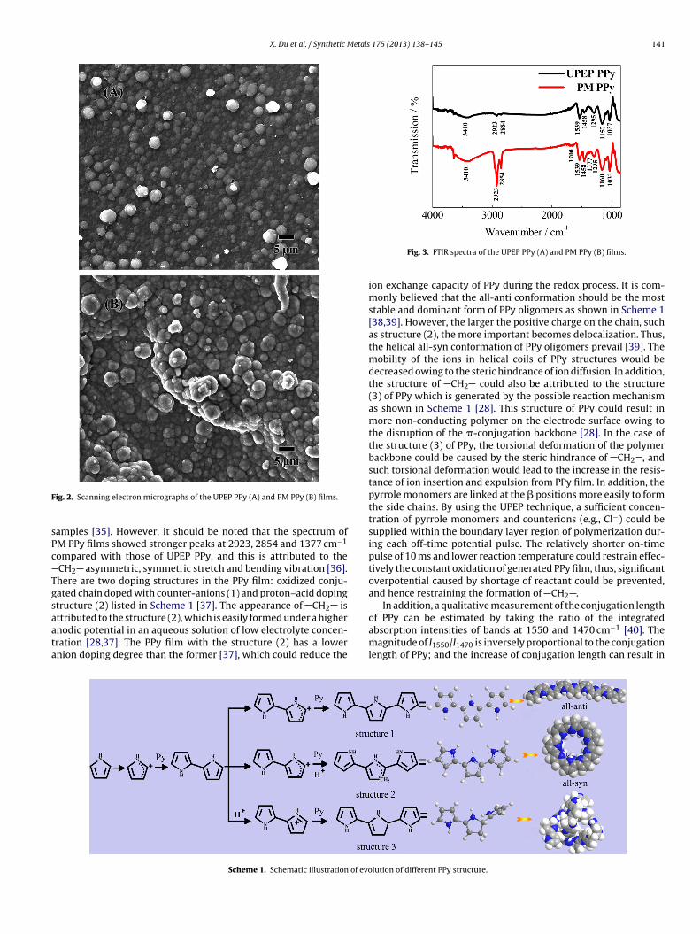
3.2.2. FT-IR spectraFT-IR spectra of UPEP PPy and PM PPy are shown in Fig. 3. Both
the UPEP PPy and PM PPy exhibited almost similar FTIR spectrum.In the spectrum, the band observed at approximately 3410 cm−1
and the peak at 1033 ± 5 cm−1 are the typical N H stretching and
ric pyrrole ring stretching vibration at 1539 and 1458 cm−1, theC H in-plane vibration at 1295 cm−1, and the C N stretching
vibration at 1160 ± 3 cm−1 are the characteristic bands of the PPy
X. Du et al. / Synthetic Metals 175 (2013) 138– 145 141
F
sPc
Tgsaata
of PPy can be estimated by taking the ratio of the integrated
ig. 2. Scanning electron micrographs of the UPEP PPy (A) and PM PPy (B) films.
amples [35]. However, it should be noted that the spectrum ofM PPy films showed stronger peaks at 2923, 2854 and 1377 cm−1
ompared with those of UPEP PPy, and this is attributed to theCH2 asymmetric, symmetric stretch and bending vibration [36].here are two doping structures in the PPy film: oxidized conju-ated chain doped with counter-anions (1) and proton–acid dopingtructure (2) listed in Scheme 1 [37]. The appearance of CH2 isttributed to the structure (2), which is easily formed under a higher
nodic potential in an aqueous solution of low electrolyte concen-ration [28,37]. The PPy film with the structure (2) has a lowernion doping degree than the former [37], which could reduce theScheme 1. Schematic illustration of evo
Fig. 3. FTIR spectra of the UPEP PPy (A) and PM PPy (B) films.
ion exchange capacity of PPy during the redox process. It is com-monly believed that the all-anti conformation should be the moststable and dominant form of PPy oligomers as shown in Scheme 1[38,39]. However, the larger the positive charge on the chain, suchas structure (2), the more important becomes delocalization. Thus,the helical all-syn conformation of PPy oligomers prevail [39]. Themobility of the ions in helical coils of PPy structures would bedecreased owing to the steric hindrance of ion diffusion. In addition,the structure of CH2 could also be attributed to the structure(3) of PPy which is generated by the possible reaction mechanismas shown in Scheme 1 [28]. This structure of PPy could result inmore non-conducting polymer on the electrode surface owing tothe disruption of the �-conjugation backbone [28]. In the case ofthe structure (3) of PPy, the torsional deformation of the polymerbackbone could be caused by the steric hindrance of CH2 , andsuch torsional deformation would lead to the increase in the resis-tance of ion insertion and expulsion from PPy film. In addition, thepyrrole monomers are linked at the � positions more easily to formthe side chains. By using the UPEP technique, a sufficient concen-tration of pyrrole monomers and counterions (e.g., Cl−) could besupplied within the boundary layer region of polymerization dur-ing each off-time potential pulse. The relatively shorter on-timepulse of 10 ms and lower reaction temperature could restrain effec-tively the constant oxidation of generated PPy film, thus, significantoverpotential caused by shortage of reactant could be prevented,and hence restraining the formation of CH2 .
In addition, a qualitative measurement of the conjugation length
absorption intensities of bands at 1550 and 1470 cm−1 [40]. Themagnitude of I1550/I1470 is inversely proportional to the conjugationlength of PPy; and the increase of conjugation length can result in
lution of different PPy structure.

142 X. Du et al. / Synthetic Metals
F
hv1bIthtgpIPottsaattpc[
3
ae(rP
ig. 4. Wettability images of water drop on UPEP PPy (A) and PM PPy (B) films.
igher conductivity of PPy [40]. In the present study, two stretchingibration bands of PPy corresponding to Ref. [40] were observed at539 and 1458 cm−1, and the difference in peak positions coulde due to different PPy preparation methods. The experimental
1539/I1458 ratios of UPEP PPy and PM PPy were 1.2 and 2.0 respec-ively, indicating that UPEP PPy had longer conjugation length andence higher conductivity than PM PPy. This analysis is also consis-ent with the experimental data. The PPy films polymerized with arowth charge of 5 C cm−2 by using the above two methods wereeeled from platinum sheets for the conductivity measurement.
t is found that the electronic conductivities of UPEP PPy and PMPy were 160 (±15) and 70 (±10) S cm−1 respectively, which werebtained by using four-point probe meter. This also indicated thathe UPEP PPy had longer conjugation length than PM PPy. Finally,he weak peak at 1700 cm−1 in the spectrum of PM PPy corre-ponds to C O stretching vibration, which could ascribed to thettack of hydroxyl radicals at the already formed polymer, knowns “overoxidation” [41]. The defects of this structure could makehe PPy film undergo irreversible degradation and hence becomeo an insulator. On the other hand, the spectra of UPEP PPy lacked aeak at 1700 cm−1 as the nucleophilic attack by hydroxyl radicalsould be minimized by ultra short on-time pulse polymerization27].
.2.3. Contact angleWettability of a solid surface is important for its application in
queous solutions. The wettability of the surface is generally gov-
rned by both surface chemistry and morphology [42]. Fig. 4(A) andB) shows the wettability images of UPEP PPy and PM PPy films,espectively. Both contact angles were less than 90◦, indicated thatPy is an intrinsically hydrophilic material. However, the contact175 (2013) 138– 145
angle of UPEP PPy film was obviously smaller than that of PM PPyfilm. The increase in contact angle is possible to be resulted by thedecreasing of surface roughness of PPy [43]. As shown in Fig. 3,UPEP PPy film exhibited a more homogeneous surface morphologythan PM PPy film. In addition, the different wettability of two PPyfilms could also be due to the diversity of PPy structure describedin the Scheme 1. For the structure (2) of PM PPy, the lower aniondoping degree could reduce the hydrophilicity of PPy [43]. In thecase of structure (3) of PPy, more compact microstructure couldalso reduce the diffusion of water molecule in the film. Both struc-tures in PM PPy film could result in a larger contact angle. Higherwettability in the UPEP PPy film is expected to lower the resis-tance of ion diffusion and improve the capacity property of thefilm.
3.3. Electrochemical characterization
3.3.1. Electro-activityCyclic voltammetry was applied for the evaluation of the capac-
itive behavior of the film. Fig. 5(A) shows the cyclic voltammetrycurves of both PPy films prepared by the two polymerization meth-ods. In general, the PPy film incorporated with small amounts ofcounterions such as Cl−, ClO4
− and SO42− exhibits anion exchanger
behavior due to the high mobility of these ions in the polymermatrix. Cation exchange could also occur under certain conditions[44]. As shown in Fig. 5(A), the peaks a and b corresponded to Cl−
ion insertion and expulsion while the peaks c and d correspondedto K+ ion expulsion and insertion, respectively [45]. Comparing tothe PM PPy film, the CV of UPEP PPy film showed larger peak cur-rent density within the same potential range, indicating that theUPEP PPy film had more excellent electroactivity under the condi-tion of same mass. Fig. 5(B) illustrates a linear variation in currentdensity of peak a as a function of scan rate. A good linear relation-ship between peak current density and scan rate suggested thatthe oxidation of PPy film could be controlled by adsorption rate.The larger slope of the linear relationship for the UPEP PPy filmshould be attributed to the ordered PPy structure [27]. Mass spe-cific capacitance of PPy was calculated according to the followingequation [46] based on CV measurement:
C = Q
m · �V= 1
m · �V
∫i dt (1)
where C, m, �V, i and t denote specific capacitance (F g−1), massof the PPy (g), scan potential range (V), response current density(A cm−2) and time span (s), respectively. In this study, the mass ofPPy was very small so that the mass ratio of the electrode to the PPywas very large, and in this case, it is difficult to evaluate the mass ofPPy accurately by weighting. Hence, the mass of PPy was calculatedby using a calculation method. Herein, all the charge generatedin the synthetic process of PM PPy film was assumed to be usedfor electro-polymerization of PPy and the electro-polymerizationcharge of UPEP PPy film was considered to be calculated by usingthe difference value between the total charge and the backgroundcharge. Thus, the calculated values of charge used for the electro-polymerization of PM PPy film and UPEP PPy film were 0.615 C cm−2
and 0.602 C cm−2 respectively. The theoretical mass of PPy film witha growth charge of 1.0 C cm−2 should be 3.32 × 10⁻⁴ g according toRef. [4], and as a result, the calculated masses of two PPy films onplatinum sheet electrode were 0.201 mg cm−2 and 0.203 mg cm−2
respectively. Fig. 5(C) shows the specific capacitance variation ofPPy with scan rates from 5 to 1000 mV s−1. It is obvious that the
specific capacitance value decreased rapidly with the increasing ofscan rate from 5 to 100 mV s−1, but slowly after 100 mV s−1. At aslow scan rate, the inner active sites of PPy could participate inredox transition with ion doping/undoping. Therefore, the specific
X. Du et al. / Synthetic Metals 175 (2013) 138– 145 143
Fig. 5. (A) Cyclic voltammetric responses of UPEP PPy and PM PPy films preparedon platinum substrate in three-electrode system. Cyclic voltammetric condition:electrolyte, 1.0 M KCl; scan rate, 50 mV s−1; scan range, −0.8 to 0.5 V, (B) kineticsof charge doping/dedoping PPy electrodes polymerized by UPEP method and PMmd
cdcacsisuPt(otp4
ethod, (C) variation of specific capacitances of UPEP PPy and PM PPy films withifferent scan rates.
apacitance value of PPy should be influenced significantly by ioniffusion rate within the electrode. In other words, ion diffusionould be restrained easily by increasing the scan rate, resulting inn obvious decrease in the capacitance value because the specificapacitance value strongly depended on the redox transition of theurface PPy at a high scan rate. Theoretically, the specific capac-tance could reach the highest if PPy film was fabricated at thelowest rate, and in this case, almost all PPy materials could betilized. Zhang et al. reported that the specific capacitance of PGMPy film was 281.0 F g−1 in 1.0 M of NaNO3 [29]. Li et al. preparedhe PPy film on stainless steel substrate by pulse deposition methodPGM) and obtained a high capacitance of 545.0 F g−1 at a scan ratef 2 mV s−1; but found that the capacitance of the PPy film dropped
o as low as 150.0 F g−1 at a scan rate of 50 mV s−1 [30]. For com-arison, in the present study, the capacitance for UPEP PPy reached06.0 F g−1 at a scan rate of 5 mV s−1 in neutral medium and wasFig. 6. Nyquist plots of the UPEP PPy (a) and PM PPy (b) film electrodes. The inset isequivalent circuit for modeling of PPy film electrodes and an enlargement of Nyquistplots respectively.
maintained at a high value of 260.0 F g−1 even when the scan ratewas increased to as high as 1000 mV s−1.
3.3.2. Electrochemical impedance spectra (EIS) analysisElectrochemical impedance spectroscopy (EIS) was used for the
investigation of the frequency response of supercapacitor. Fig. 6shows Nyquist plots of the EIS data for the UPEP PPy and PMPPy films under open circuit potential (OCP) in 1.0 M of KCl. Theimpedance curves of both PPy electrodes showed similar distortedsemi-circle in the high frequency region and a straight line inthe low frequency region. The diameter of the semi-circle corre-sponded to the interfacial charge transfer resistance (Rct) and theintercept of the semi-circle on the real axis yielded the solutionresistance (Rsol) [12]. The experimental EIS data were fitted to anequivalent circuit as shown in the inset of Fig. 6, where CPE1 andCPE2 denote constant phase element, which can be used to describethe double layer capacitance at the interface and the pseudo capac-itance from ion transfer in the PPy film, respectively. The Rct valuesof UPEP PPy and PM PPy films were 4.57 � and 10.51 �, respec-tively. The smaller Rct of 4.57 � indicated that the UPEP PPy filmhad higher ion exchange ability, which could be related to its betterwettability and higher apparent diffusion coefficient. Furthermore,the UPEP PPy film exhibited a steeper profile than PM PPy film in thelow frequency region, indicating more excellent capacitor behavior.
3.3.3. Galvanostatic charge–discharge characteristicsTo further evaluate the actual performance of PPy film as
electrode material for practical application in supercapacitor,a symmetrical two-electrode system was designed. Galvano-static charge/discharge measurements at various current densitieswere carried out. Fig. 7(A) shows the typical galvanostaticcharge/discharge curves of UPEP PPy and PM PPy films with anapplied constant current density of 10 A g−1 in 1.0 M of KCl aqueoussolution. A near perfect linear variation of cell voltage versus timewas observed from the charge/discharge curve of UPEP PPy, whichalso indicated that this film had good capacitance performance [47].In addition, there was a remarkable initial drop in voltage observedfrom the charge/discharge curve of the PM PPy film. A similar phe-nomenon was also observed from the charge/discharge curve of thePPy film prepared by chemical polymerization [48] and CV poly-merization method [12], which was caused by internal resistanceof PPy film. The smaller voltage drop of UPEP PPy electrode indi-cated that it had better electron and ion transport properties. Thespecific capacitance in a two-electrode system was calculated as
follows [49]:Cm = 2I × �t
�V × m(2)

144 X. Du et al. / Synthetic Metals 175 (2013) 138– 145
Fig. 7. (A) Galvanostatic charge/discharge curves of UPEP PPy and PM PPy films int −1
a2
wdmPcofPts
3
acacfct0otv1psfirt
References
wo-electrode system at a current density of 10 A g in 1 M KCl aqueous solutionnd (B) the specific capacitances of PPy films at different current densities of 1, 10,0, 30,40, 50 A g−1 respectively.
here C, I, �t, �V and m are specific capacitance of active material,ischarge current, discharge time, voltage window of discharge andass of active material, respectively. The specific capacitance of
Py electrode is presented in Fig. 7(B). One can see that the specificapacitance reached 260.0 F g−1 even at a discharge current densityf 50 A g−1. With the increase in charge/discharge current densityrom 1 to 50 A g−1, the specific capacitances of UPEP PPy and PMPy films reduced by 25% and 41% respectively. This indicated thathe UPEP PPy film had a very low ion diffusion resistance even atuch a high charge/discharge current density.
.3.4. Cycling stabilityThe PPy film was always found to have high discharge capacity
nd good cycling stability in acidic solution, because the irreversibleapacitance degradation caused by over-oxidation of PPy wasvoided in low pH solution [36]. However, in neutral solution, theycling stability of PPy film prepared by conventional methods wasound to be unsatisfactory. Dubal et al. [12] prepared porous PPylusters by potentiodynamic polymerization method and foundhat the loss of capacitance was about 19% after 5000 cycles in.5 M of H2SO4 electrolyte and the decay of capacitance mainlyccurred in the initial 1000 cycles. Zhang et al. [50] reported thathe specific capacitance of a graphene/PPy composite synthesizedia in situ polymerization retained 96% of its initial value after000 cycles in 1.0 M of H2SO4 electrolyte. Wang et al. [28] pre-ared the PPy film by pulse current polymerization on tantalum
heet and found that the decay of specific capacitance for the PPylm was about 14.5% after 50,000 cycles at a charge/discharge cur-ent of 20 A g−1 in 3.0 M of KCl electrolyte. In the present study,he long term stability of two symmetrical films was examined byFig. 8. Cycling life of UPEP PPy and PM PPy films as a two-electrode cell configurationunder a current density of 50 A g−1 in 1 M KCl aqueous solution.
galvanostatic charge/discharge cycling at a current density of50 A g−1 in 1.0 M of KCl solution, and the results are shown in Fig. 8.The specific capacitance of UPEP PPy exhibited an excellent cyclingstability, with only 7.4% decay from its initial capacitance even after50,000 cycles. In addition, there was almost no obvious attenuationin the initial stage of galvanostatic charge–discharge measurement.As stated above, the UPEP PPy film exhibited more homogeneousparticle distribution, which could relieve partly volumetric stresscaused by volume changes of PPy during the oxidation/reductioncycles and hence improve the reversibility and stability of the PPyfilm. The excellent wettability and conductivity of the UPEP PPyfilm, comparing with that of the PM PPy film, is benefit to reducethe resistance of ion diffusion and improve the efficiency of chargetransfer, and thus improve the capacity property of films. In addi-tion, the structural defects of PPy, which can make PPy undergoirreversible degradation, could be inhibited by using UPEP method.In conclusions, the surface morphology, conjugation length andspatial conformation of UPEP PPy could be effectively improvedduring the electro-polymerization process. This can make PPy filmhave higher conductivity and better wettability, thereby result inhigher cycle stability.
4. Conclusions
Highly stable PPy film was successfully synthesized by usinga facile UPEP method. UPEP PPy film exhibited an ordered struc-ture with reduced chain defects. Such a structure improved thehydrophilicity and charge transfer rate of the film. EIS measure-ments indicated that the UPEP PPy film provided lower impedancethan the PM PPy film. The PPy films prepared by UPEP methodshowed a specific capacitance as high as 406.0 F g−1 at a scanrate of 5 mV s−1 and an excellent cycling stability, with only 7.4%decay from its initial capacitance even after 50,000 cycles at acharge/discharge current of 50 A g−1.
Acknowledgements
This work was financially supported by the National NaturalScience Foundation of China (No. 21276173), Natural Science Foun-dation of Shanxi Province (No. 2012011020-5 and 2012011006-1),International Joint Research Project of Shanxi Province (No.2011081028) and JSPS KAKENHI Grant Number 24651066.
[1] X.F. Lu, W.J. Zhang, C. Wang, T.C. Wen, Y. Wei, Progress in Polymer Science 36(2011) 671.
[2] P. Simon, Y. Gogotsi, Nature Materials 7 (2008) 845.

etals
[
[
[
[
[
[[
[
[[[
[[
[[[
[
[
[
[
[[
[
[
[[[[[[
[[
[[
[[[
[
X. Du et al. / Synthetic M
[3] G.A. Snook, P. Kao, A.S. Best, Journal of Power Sources 196 (2011) 1.[4] C.C. Hu, X.X. Lin, Journal of the Electrochemical Society 149 (2002) A1049.[5] B.C. Kim, C.O. Too, J.S. Kwon, J.M. Ko, G.G. Wallace, Synthetic Metals 161 (2011)
1130.[6] Y.K. Zhou, B.L. He, W.J. Zhou, J. Huang, X.H. Li, B. Wu, H.L. Li, Electrochimica Acta
49 (2004) 257.[7] B. Muthulakshmi, D. Kalpana, S. Pitchumani, N.G. Renganathan, Journal of
Power Sources 158 (2006) 1533.[8] M.N. Akieh, R.M. Latonen, S. Lindholm, S.F. Ralph, J. Bobacka, A. Ivaska, Synthetic
Metals 161 (2011) 1906.[9] B. Ding, X.J. Lu, C.Z. Yuan, S.D. Yang, Y.Q. Han, X.G. Zhang, Q. Che, Electrochimica
Acta 62 (2012) 132.10] B.C. Thompson, S.E. Moulton, R.T. Richardson, G.G. Wallace, Biomaterials 32
(2011) 3822.11] I. Carrillo, E.S. de la Blanca, M.I. Redondo, M.V. García, M.J. González-Tejera,
J.L.G. Fierro, E. Enciso, Synthetic Metals 162 (2012) 136.12] D.P. Dubal, S.H. Lee, J.G. Kim, W.B. Kim, C.D. Lokhande, Journal of Materials
Chemistry 22 (2012) 3044.13] D.C. Wu, F. Xu, B. Sun, R.W. Fu, H.K. He, K. Matyjaszewski, Chemical Reviews
112 (2012) 3959.14] K. Fukami, F.A. Harraz, T. Yamauchi, T. Sakka, Y.H. Ogata, Electrochemistry
Communications 10 (2008) 56.15] M. Wei, T.Y. Dai, Y. Lu, Synthetic Metals 160 (2010) 849.16] J. Joo, J.K. Lee, S.Y. Lee, K.S. Jang, E.J. Oh, A.J. Epstein, Macromolecules 33 (2000)
5131.17] K.F. Babu, R. Senthilkumar, M. Noel, M.A. Kulandainathan, Synthetic Metals 159
(2009) 1353.18] B.C. Kim, J.M. Ko, G.G. Wallace, Journal of Power Sources 177 (2008) 665.19] J.C. Vidal, E. Garcia, J.R. Castillo, Biosensors and Bioelectronics 13 (1998) 371.20] P.A. Fiorito, S.I. Córdoba de Torresi, Journal of Electroanalytical Chemistry 581
(2005) 31.21] P.A. Fiorito, C.M.A. Brett, S.I. Córdoba de Torresi, Talanta 69 (2006) 403.22] H.H. Zhou, J.B. Wen, X.H. Ning, C.P. Fu, J.H. Chen, Y.F. Kuang, Synthetic Metals
157 (2007) 98.23] M.S. Kiani, N.V. Bhat, F.J. Davis, G.R. Mitchell, Polymer 33 (1992) 4113.24] H.F. Jiang, X.X. Liu, Electrochimica Acta 55 (2010) 7175.25] A. Davies, P. Audette, B. Farrow, F. Hassan, Z.W. Chen, J.Y. Choi, A.P. Yu, Journal
of Physical Chemistry C 115 (2011) 17612.
[[
[
175 (2013) 138– 145 145
26] Y.P. Fang, J.W. Liu, D.J. Yu, J.P. Wicksted, K. Kalkan, C.O. Topal, B.N. Flanders, J.Wu, J. Li, Journal of Power Sources 195 (2010) 674.
27] R.K. Sharma, A.C. Rastogi, S.B. Desu, Electrochemistry Communications 10(2008) 268.
28] J.P. Wang, Y.L. Xu, J. Wang, X.F. Du, F. Xiao, J.B. Li, Synthetic Metals 160 (2010)1826.
29] J. Zhang, L.B. Kong, H. Li, Y.C. Luo, L. Kang, Journal of Materials Science 45 (2010)1947.
30] X. Li, I. Zhitomirsky, Materials Letters 76 (2012) 15.31] X.G. Hao, T. Yan, Z.D. Wang, S.B. Liu, Z.H. Liang, Y.H. Shen, M. Pritzker, Thin Solid
Films 520 (2012) 2438.32] Y. Li, K. Zhao, X. Du, Z.D. Wang, X.G. Hao, S.B. Liu, G.Q. Guan, Synthetic Metals
162 (2012) 107.33] Z.D. Wang, X.G. Hao, Z.L. Zhang, S.B. Liu, Z.H. Liang, G.Q. Guan, Sensors and
Actuators B 162 (2012) 353.34] P. Yang, J. Zhang, Y. Guo, Applied Surface Science 255 (2009) 6924.35] C. He, C.H. Yang, Y.F. Li, Synthetic Metals 139 (2003) 539.36] M.E. Nicho, H. Hu, Solar Energy Materials and Solar Cells 63 (2000) 423.37] Y.F. Li, G.F. He, Synthetic Metals 94 (1998) 127.38] Y.F. Dai, E. Blaisten-Barojas, Journal of Chemical Physics 129 (2008) 164903.39] J. Tamm, U. Johanson, M. Marandi, T. Tamm, L. Tamm, Russian Journal of Elec-
trochemistry 40 (2004) 344.40] W.B. Liang, J.T. Lei, C.R. Martin, Synthetic Metals 52 (1992) 227.41] C. Debiemme-Chouvy, T.T.M. Tran, Electrochemistry Communications 10
(2008) 947.42] B.W. Xin, J.C. Hao, Chemical Society Reviews 39 (2010) 769.43] K.S. Teh, Y. Takahashi, Z.H. Yao, Y.W. Lu, Sensors and Actuators A 155 (2009)
113.44] C. Weidlich, K.M. Mangold, K. Jüttner, Electrochimica Acta 50 (2005) 1547.45] C.Y. Jin, F.L. Yang, Sensors and Actuators B 114 (2006) 737.46] H.F. An, Y. Wang, X.Y. Wang, L.P. Zheng, X.Y. Wang, L.H. Yi, L. Bai, X.Y. Zhang,
Journal of Power Sources 195 (2010) 6964.47] Y.G. Wang, L. Cheng, Y.Y. Xia, Journal of Power Sources 153 (2006) 191.
48] H. Lee, H. Kim, M.S. Cho, J. Choi, Y. Lee, Electrochimica Acta 56 (2011) 7460.49] J. Wang, Y.L. Xu, X. Chen, X.F. Du, Journal of Power Sources 163 (2007)1120.50] D.C. Zhang, X. Zhang, Y. Chen, P. Yu, C.H. Wang, Y.W. Ma, Journal of Power
Sources 196 (2011) 5990.


![ars.els-cdn.com · Web view[2] L. Yang, S. Zhou, W. Yang, Polypyrrole directly bonded to air-plasma activated carbon nanotube as electrode materials for high-performance supercapacitor,](https://img.pdfslide.us/doc/110x75/5faf1e8c53c3691232417491/arsels-cdncom-web-view-2-l-yang-s-zhou-w-yang-polypyrrole-directly-bonded.jpg)