Embed Size (px)
Citation preview
High Volume Intersection Study, Vol. I
Innovative Intersections: Overview and Implementation Guidelines
prepared for
Community Planning Associationof Southwest Idaho
April 21, 2008
submitted by
Wilbur Smith Associatesin association with
The High Volume Intersection Study (HVIS) consists of three volumes:
Vol. I Innovative Intersections: Overview and Implementation Guidelines, broadly outlines information about a variety of innovative intersection concepts and provides more specific implementation guidelines for intersection types that appear to be most applicable to southwest Idaho.
Vol. II Intersection Concept Layout Report, features spotlighted high volume intersection concepts at nine different intersections in Ada County.
Vol. III Additional Materials, includes a compatibility matrix between intersection types and urban forms and street functional classifications.
The Community Planning Association of Southwest Idaho (COMPASS) contracted with Wilbur Smith Associates for this study, with additional contributions by Thompson Transportation, HDR, and Joseph E. Hummer, Ph.D., P.E.
High Volume Intersection Study, Vol. I Innovative Intersections: Overview and Implementation Guidelines Table Of Contents
COMPASS – Community Planning Association of Southwest Idaho April 2008 / i
Table of Contents
Acronyms and Terms .............................................................................................. iii
1. Introduction ...................................................................................................... 1-1
1.1. What is an “Innovative Intersection”? .......................................................... 1-1
1.2. Public Acceptance of Innovative Intersections .............................................. 1-2
1.3. Advancing From Concept to Construction .................................................. 1-3
1.4. Driver Expectancy ........................................................................................ 1-3 How Important is Driver Expectancy? ............................................... 1-4
2. Innovative Intersection Concepts ..................................................................... 2-1
2.1. Continuous Flow Intersection (CFI) ............................................................. 2-1
2.2. Parallel Flow Intersection (PFI) .................................................................... 2-2
2.3. Town Center Intersections (TCI) .................................................................. 2-3
2.4. Median U-Turn (Michigan Left Turn) .......................................................... 2-5
2.5. Bowtie – an Enhanced Median U-Turn ......................................................... 2-6 Center Oval – Aesthetically Pleasing, Functionally Efficient ............ 2-7
2.6. Superstreet .................................................................................................... 2-8
2.7. Quadrant Roadway Intersection (QRI) ......................................................... 2-8
2.8. Jughandle/Mini-Cloverleaf Intersections ...................................................... 2-12
2.9. Roundabouts ................................................................................................. 2-12
2.10. Grade-Separated Innovative Designs (Arterial Interchanges) ........................ 2-13 Center Left-Turn Overpass ............................................................... 2-13 Echelon Interchange .......................................................................... 2-14 Other Arterial Interchanges .............................................................. 2-14
2.11. Summary of Comparative Advantages and Disadvantages ........................... 2-15 At-Grade Intersections ...................................................................... 2-15 Arterial Interchanges ......................................................................... 2-18
2.12. Intersection Toolbox: What, When, Where, Why ......................................... 2-19
3. Implementing Continuous Flow Intersections ................................................. 3-1
3.1. Intersection and Roadway Design ................................................................. 3-1 General Description ............................................................................ 3-1 Lane Geometry and Footprint ............................................................ 3-1 Operations and Signalization .............................................................. 3-4 Capacity ............................................................................................... 3-5 Typical Cost Range ............................................................................. 3-5
High Volume Intersection Study, Vol. I Innovative Intersections: Overview and Implementation Guidelines Table Of Contents
COMPASS – Community Planning Association of Southwest Idaho April 2008 / ii
3.2. Streetscape, Access and Site Design ............................................................... 3-6 Streetscaping and Multimodal Accommodations ............................... 3-6 Access Management ............................................................................. 3-9 Site Design on Adjacent Land ........................................................... 3-10
4. Implementing Median U-Turns and Bowties .................................................... 4-1
4.1. Intersection and Roadway Design ................................................................. 4-1 General Description ............................................................................ 4-1 Lane Geometry and Footprint ............................................................ 4-1 Operations and Signalization .............................................................. 4-2 Capacity ............................................................................................... 4-3 Typical Cost Range ............................................................................. 4-3
4.2. Streetscape, Access and Site Design ............................................................... 4-4 Streetscaping ........................................................................................ 4-4 Signage ................................................................................................. 4-4 Multimodal Accommodations ............................................................ 4-4 Access and Land Use Standards ........................................................... 4-4
5. Implementing Quadrant Roadways .................................................................. 5-1
5.1. Intersection and Roadway Design ................................................................. 5-1 General Description ............................................................................ 5-1 Lane Geometry and Footprint ............................................................ 5-1 Operations and Signalization .............................................................. 5-2 Capacity ............................................................................................... 5-3 Typical Cost Range ............................................................................. 5-3
5.2. Streetscape, Access and Site Design ............................................................... 5-4 Streetscaping ........................................................................................ 5-4 Signage ................................................................................................. 5-4 Multimodal Accommodations ............................................................ 5-4 Access and Land Use Standards ........................................................... 5-4
References ............................................................................................................... R-1
High Volume Intersection Study, Vol. I Innovative Intersections: Overview and Implementation Guidelines Acronyms And Terms
COMPASS – Community Planning Association of Southwest Idaho April 2008 / iii
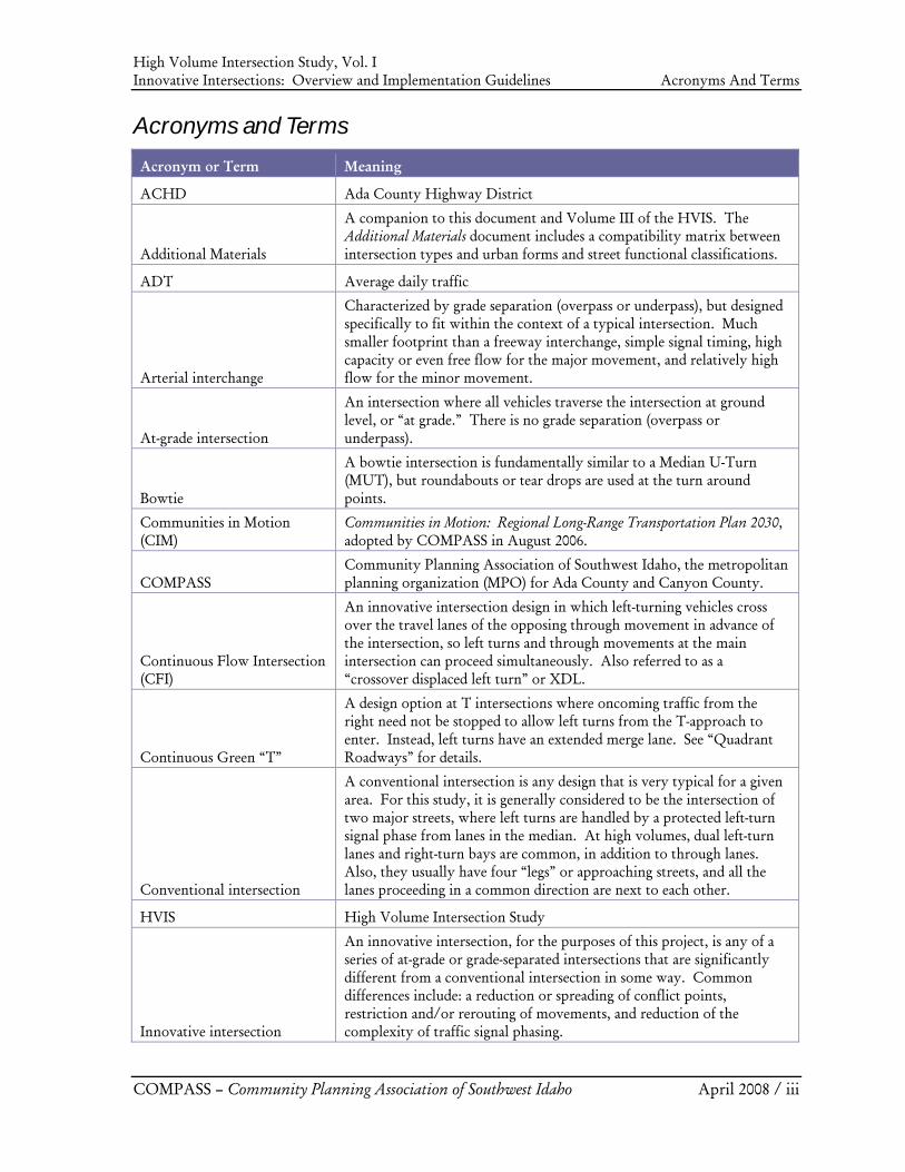
Acronyms and Terms
Acronym or Term Meaning
ACHD Ada County Highway District
Additional Materials
A companion to this document and Volume III of the HVIS. The Additional Materials document includes a compatibility matrix between intersection types and urban forms and street functional classifications.
ADT Average daily traffic
Arterial interchange
Characterized by grade separation (overpass or underpass), but designed specifically to fit within the context of a typical intersection. Much smaller footprint than a freeway interchange, simple signal timing, high capacity or even free flow for the major movement, and relatively high flow for the minor movement.
At-grade intersection
An intersection where all vehicles traverse the intersection at ground level, or “at grade.” There is no grade separation (overpass or underpass).
Bowtie
A bowtie intersection is fundamentally similar to a Median U-Turn (MUT), but roundabouts or tear drops are used at the turn around points.
Communities in Motion (CIM)
Communities in Motion: Regional Long-Range Transportation Plan 2030, adopted by COMPASS in August 2006.
COMPASS Community Planning Association of Southwest Idaho, the metropolitan planning organization (MPO) for Ada County and Canyon County.
Continuous Flow Intersection (CFI)
An innovative intersection design in which left-turning vehicles cross over the travel lanes of the opposing through movement in advance of the intersection, so left turns and through movements at the main intersection can proceed simultaneously. Also referred to as a “crossover displaced left turn” or XDL.
Continuous Green “T”
A design option at T intersections where oncoming traffic from the right need not be stopped to allow left turns from the T-approach to enter. Instead, left turns have an extended merge lane. See “Quadrant Roadways” for details.
Conventional intersection
A conventional intersection is any design that is very typical for a given area. For this study, it is generally considered to be the intersection of two major streets, where left turns are handled by a protected left-turn signal phase from lanes in the median. At high volumes, dual left-turn lanes and right-turn bays are common, in addition to through lanes. Also, they usually have four “legs” or approaching streets, and all the lanes proceeding in a common direction are next to each other.
HVIS High Volume Intersection Study
Innovative intersection
An innovative intersection, for the purposes of this project, is any of a series of at-grade or grade-separated intersections that are significantly different from a conventional intersection in some way. Common differences include: a reduction or spreading of conflict points, restriction and/or rerouting of movements, and reduction of the complexity of traffic signal phasing.
High Volume Intersection Study, Vol. I Innovative Intersections: Overview and Implementation Guidelines Acronyms And Terms
COMPASS – Community Planning Association of Southwest Idaho April 2008 / iv
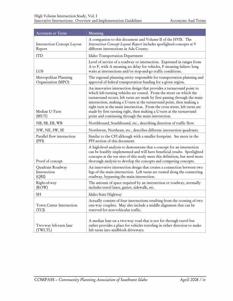
Acronym or Term Meaning
Intersection Concept Layout Report
A companion to this document and Volume II of the HVIS. The Intersection Concept Layout Report includes spotlighted concepts at 9 different intersections in Ada County.
ITD Idaho Transportation Department
LOS
Level of service of a roadway or intersection. Expressed in ranges from A to F, with A meaning no delay for vehicles, F meaning failure: long waits at intersections and/or stop-and-go traffic conditions.
Metropolitan Planning Organization (MPO)
The regional planning entity responsible for transportation planning and approval of federal transportation funding for a given region.
Median U-Turn (MUT)
An innovative intersection design that provides a turnaround point to which left-turning vehicles are routed. From the street on which the turnaround occurs, left turns are made by first passing through the main intersection, making a U-turn at the turnaround point, then making a right turn at the main intersection. From the cross street, left turns are made by first turning right, then making a U-turn at the turnaround point and continuing through the main intersection.
NB, SB, EB, WB Northbound, Southbound, etc., describing direction of traffic flow.
NW, NE, SW, SE Northwest, Northeast, etc., describes different intersection quadrants.
Parallel flow intersection (PFI)
Similar to the CFI although with a smaller footprint. See more in the PFI section of this document.
Proof of concept
A high-level analysis to demonstrate that a concept for an intersection can be feasibly implemented and will have beneficial results. Spotlighted concepts at the ten sites of this study meet this definition, but need more thorough analysis to develop the concepts and competing concepts.
Quadrant Roadway Intersection (QRI)
An innovative intersection design that creates a connection between two legs of the main intersection. Left turns are routed along the connecting roadway, bypassing the main intersection.
Right-of-way (ROW)
The amount of space required by an intersection or roadway, normally includes travel lanes, gutter, sidewalk, etc.
SH Idaho State Highway
Town Center Intersection (TCI)
Actually consists of four intersections resulting from the crossing of two one-way couplets. May also include a middle alignment that can be reserved for non-vehicular traffic.
Two-way left-turn lane (TWLTL)
A median lane on a two-way road that is not for through travel but rather provides a place for vehicles traveling in either direction to make left turns into midblock driveways.
High Volume Intersection Study, Vol. I Chapter 1 Innovative Intersections: Overview and Implementation Guidelines Introduction
COMPASS – Community Planning Association of Southwest Idaho April 2008 / 1-1
1. Introduction
The Community Planning Association of Southwest Idaho (COMPASS) adopted Communities in Motion: Regional Long-Range Transportation Plan 2030 (CIM) in August 2006. COMPASS, as a part of its metropolitan planning organization (MPO) responsibilities, developed the plan for the region with the assistance of its member agencies. The High Volume Intersection Study (HVIS) was initiated in response to findings and policy statements that appear in CIM. A key objective of the HVIS is to develop guidelines and recommendations for implementing innovative intersection designs in the region. The project team prepared this report as a means of helping COMPASS achieve that objective. The recommendations in this report are suitable for use by highway agencies, cities, counties, and by other agencies/jurisdictions throughout the COMPASS region. This report’s recommendations will help land use agencies establish standards for innovative intersection types, which will facilitate implementation of innovative intersections throughout the COMPASS region. Information from the report may also be useful for updating the regional travel demand model.
1.1. What is an “Innovative Intersection”?
For this document, a conventional high-capacity intersection typically would have a dedicated pocket for right turns, 2-3 through lanes per direction, and double left-turn pockets with left-turn arrows. This results in a 4-phase signal (a left phase and a through phase for the two directions of one street, and the same on the cross street). An innovative intersection is generally defined as any at-grade design concept that is able to reduce the number of phases at the main intersection, thereby increasing the efficiency and capacity of the signal. In most cases this is accomplished by rerouting left turns at a point well ahead of the main intersection, or to require the driver to do something unusual, such as first go through, then make a U-turn, and finally a right turn. They tend to be uncommon for several reasons: Why are innovative intersections uncommon? How are these reasons changing? • Lack of industry awareness – many are
relatively new ideas. • Rate of implementation is increasing, and so
is exposure and confidence. • Though the cost/benefit ratio is often very
good, they still typically cost more than a conventional intersection.
• Cost/benefit ratio improves as traffic increases.
• In some cases they are out of context or don’t work in a particular location.
• Solutions are tailored to each site.
• Usually requires turning movements that differ from typical driver expectations.
• Driver reaction is generally positive (prefer a change if it saves significant time).
• Problems at conventional intersections have historically been tolerable in spite of their inefficiency.
• Major congestion is motivating many to search for solutions that are better than a conventional intersection but not as expensive/intrusive as an interchange.
High Volume Intersection Study, Vol. I Chapter 1 Innovative Intersections: Overview and Implementation Guidelines Introduction
COMPASS – Community Planning Association of Southwest Idaho April 2008 / 1-2
In spite of these challenges, the major redeeming virtue of all innovative intersections is that congestion relief is often extremely good, and their relative cost is in many cases very modest. They often improve safety by reducing the number of conflict points. Some concepts reduce the pressure on a single large intersection by creating a number of smaller intersections to help handle left turns. In these cases, the number of conflict points may remain unchanged or even increase, but the overall safety and flow of the system is nonetheless improved because each intersection is much simpler. Many of these designs are not new, and are “tried and true” in certain parts of the U.S., in which cases they enjoy good driver expectancy because they are common. Typical conditions under which a conventional intersection may fail include:
• Heavy traffic volumes on opposing movements, such as left turns in one direction and the opposing through movement.
• A high number of conflict points, resulting both from movements at the intersection itself and at upstream driveways and weaving areas (ie, areas where significant numbers of vehicles are making conflicting lane change maneuvers).
• High traffic volume on several movements requires complex traffic signal phasing, leading to longer cycle lengths, more “lost time” between phases, and longer delays.
Innovative at-grade designs typically address such problems by:
• Reducing the number of conflict points, or improving safety and capacity by spreading them out
• Restricting and/or rerouting movements • Reducing the complexity of traffic signal phasing
1.2. Public Acceptance of Innovative Intersections
Regardless of how attractive any particular innovative intersection appears in the analysis phase, implementing agencies must first be convinced that drivers in their area can safely navigate the design. Because so many of the concepts require restricted access or circuitous movements, agencies must also gain confidence that the public understands the benefits and is willing to accept the negative aspects to obtain the positive. Therefore, it is critical that any serious proposal to try something new in a given region be accompanied by a significant public awareness campaign. Such a campaign should not shy away from highlighting the negative aspects of agency-preferred solutions, because it is critical for the public to comprehend all angles so they can respond from an informed position. The accompanying study of 10 high-volume intersections in the Boise area has generated several preliminary concepts that involve innovative intersections. The study has developed high-quality graphics, proof-of-concept planning-level analysis, and identified needed right-of-way to help generate excitement and allow for corridor preservation. However, agencies should spend significantly more time and resources refining all of the top two or three concepts to truly arrive at a complete understanding of the myriad of issues surrounding each design.
High Volume Intersection Study, Vol. I Chapter 1 Innovative Intersections: Overview and Implementation Guidelines Introduction
COMPASS – Community Planning Association of Southwest Idaho April 2008 / 1-3
1.3. Advancing From Concept to Construction
In a recent survey of 26 state highway officials, 16 (62%), rated concerns over driver expectancy and safety as the top reason they would hesitate to advocate an innovative design in spite of any other positive aspects. The second highest concern, with 8 number one votes (31%), was concern over the likely cost. Clearly concerns over safety and driver expectancy must be taken extremely seriously if anything other than an inefficient-but-familiar design style is to be adopted. Suggestions for advancing beyond the “proof of concept” stage:
1. Local demonstration: Select the most promising location for a particular concept. 2. System analysis: Expand the analysis beyond just an intersection, but to a contained
system that may involve nearby intersections, driveways, etc. 3. Expert simulation: Enlist a respected expert to test all the top-tier concepts in a high-
accuracy simulation tool. 4. 3-D animations: In the simulations, develop 3-D renderings complete with landscaping,
etc. so that stakeholders and the public at large can better understand what they’re actually getting with a given proposal.
5. Near-term performance: Test potential solutions in the far future, but also against conditions expected in the next five years so the public can see immediate value.
6. Detailed impacts study: Study the access effects to adjacent properties in detail. Refine cost estimates and right-of-way needs for each concept.
7. Well-crafted information: Present both positive and negative findings through a well-crafted process to engage key stakeholders, and randomly selected focus-groups to better understand public concerns and opinions once they are well educated on the subject.
8. Focus group feedback: Propose signage and other features to improve driver expectancy; obtain focus-group feedback on the level to which they value expectancy vs. efficiency, and whether proposed mitigations are sufficient to win their support.
If it appears the design will be at least as safe as conventional alternatives, stakeholders will likely be more willing to incur the cost, and the public can tolerate less than perfect driver expectancy to improve the overall operation of the intersection. The drive expectancy can be improved through good signage, vehicle channeling, and driver awareness campaigns as construction nears completion. The next step is to select the most promising design at the most promising location and construct it as a demonstration project to show the benefits of the improvement. To the extent that it is well-received and performs as expected, carry the concept to other locations. As noted in item #2 above, system considerations should count heavily in the determination of suitable locations, particularly in the near term. Agency and public enthusiasm for a new and promising intersection type will disappear quickly if the problems at one location are solved only to create an intensified problem at a nearby location.
1.4. Driver Expectancy
Since agencies have noted that driver expectancy is their top concern, a discussion on driver expectancy is warranted. By definition, perfect driver expectancy can only be achieved with a locally common design. This is because part of what makes the intersection easy for most drivers to navigate is that it is very similar to dozens if not hundreds of others that they’re familiar with elsewhere. However, intersections with perfect driver expectancy are often unacceptably congested, invoking a need to make tradeoffs.
High Volume Intersection Study, Vol. I Chapter 1 Innovative Intersections: Overview and Implementation Guidelines Introduction
COMPASS – Community Planning Association of Southwest Idaho April 2008 / 1-4
Driver expectancy for making a left turn on an arterial
Perfect expectancy: Driver enters the left lane just ahead of the intersection, or intersection navigation is typical of many others in the region.
Good expectancy: Driver enters left-turn pocket ahead of the intersection, but sometimes considerably ahead. Paths to complete left turns are not typical in the region, but locals are quickly accustomed. Visitors who miss signs can safely find a course correction.
Unusual expectancy: Making a left turn ahead of the intersection is not possible, and the navigation style is not common. Left turns are accomplished as “Right-U-Through,” “Through-U-Right,” “3-Rights is a Left,” or any system that requires a driver to do something they are not accustomed to doing in that environment.
It is possible for intersection types to move between these categories, depending on their level of use in an area. The Median U-Turn (MUT) would qualify as unusual in Boise, but in many locales in Michigan it is so common as to achieve near perfect expectancy. Jughandles (mini-cloverleafs) are similarly unusual for Boise, but perfectly common in New Jersey. In Boise, the traditional double left-turn pocket with a protected arrow phase would qualify as perfect expectancy. Roundabouts once qualified as unusual, but are quickly moving to the good if not perfect expectancy category. Continuous Flow Intersections (CFI), Parallel Flow Intersections (PFI), Town Center one-ways, and 4-quadrant roadways would all qualify as having good expectancy in Boise because they require entering a left pocket ahead of the intersection. MUTs, Bowties, Jughandles, and one- or two-quadrant roadways would be considered unusual both because they are uncommon, and because they require an unconventional left-turn maneuver. Grade-separated intersections are “unusual” in a non-freeway context, because they require an unexpected exit from the right-hand ramp to make a left.
How Important is Driver Expectancy? Unusual driver expectancy should not automatically disqualify a concept from consideration unless for some reason it creates an unsafe situation. These options are often far less costly to implement relative to other choices, and in some cases require only changing signs, striping, and signal timing. Perfect driver expectancy also comes with high congestion at high volumes. Most drivers would prefer to get used to a new expectancy if it means they’ll save a lot of time. The next section introduces a number of innovative intersection concepts. Later chapters provide more in-depth discussion of several types that appear attractive for general application in the Boise area.
High Volume Intersection Study, Vol. I Chapter 2 Innovative Intersections: Overview and Implementation Guidelines Innovative Intersection Concepts
COMPASS – Community Planning Association of Southwest Idaho April 2008 / 2-1
2. Innovative Intersection Concepts
Continuous Flow, Parallel Flow, Town Center, Bowties, Superstreets, Quadrants, MUTs, and Roundabouts – these are promising new designs for urban intersections that are context sensitive, incredibly efficient, and often surprisingly affordable especially if such a design is envisioned when adjacent land uses are first established. Compared to a freeway interchange, these intersections can often accommodate 70% (or more) of the traffic served by a grade separated option and cost about 30% (sometimes less) of what it costs to construct a grade separated intersection/interchange. This section provides a brief description of some of these emerging innovative intersections.
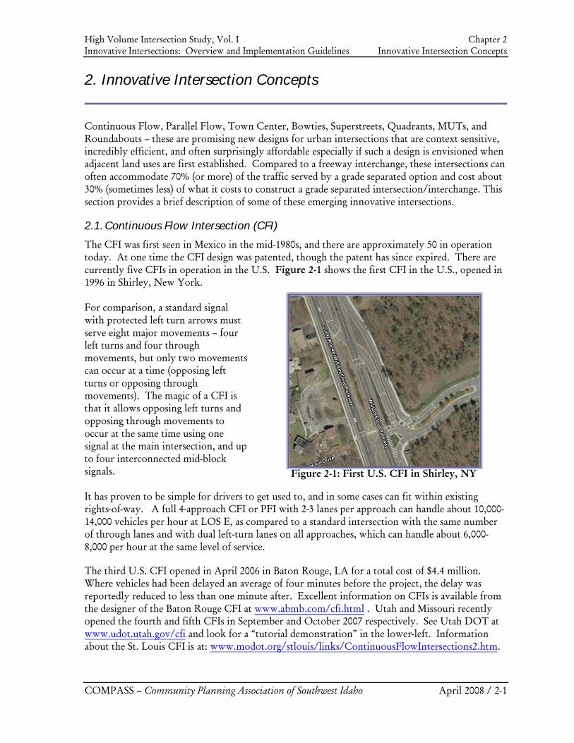
2.1. Continuous Flow Intersection (CFI)
The CFI was first seen in Mexico in the mid-1980s, and there are approximately 50 in operation today. At one time the CFI design was patented, though the patent has since expired. There are currently five CFIs in operation in the U.S. Figure 2-1 shows the first CFI in the U.S., opened in 1996 in Shirley, New York. For comparison, a standard signal with protected left turn arrows must serve eight major movements – four left turns and four through movements, but only two movements can occur at a time (opposing left turns or opposing through movements). The magic of a CFI is that it allows opposing left turns and opposing through movements to occur at the same time using one signal at the main intersection, and up to four interconnected mid-block signals. It has proven to be simple for drivers to get used to, and in some cases can fit within existing rights-of-way. A full 4-approach CFI or PFI with 2-3 lanes per approach can handle about 10,000-14,000 vehicles per hour at LOS E, as compared to a standard intersection with the same number of through lanes and with dual left-turn lanes on all approaches, which can handle about 6,000-8,000 per hour at the same level of service. The third U.S. CFI opened in April 2006 in Baton Rouge, LA for a total cost of $4.4 million. Where vehicles had been delayed an average of four minutes before the project, the delay was reportedly reduced to less than one minute after. Excellent information on CFIs is available from the designer of the Baton Rouge CFI at www.abmb.com/cfi.html . Utah and Missouri recently opened the fourth and fifth CFIs in September and October 2007 respectively. See Utah DOT at www.udot.utah.gov/cfi and look for a “tutorial demonstration” in the lower-left. Information about the St. Louis CFI is at: www.modot.org/stlouis/links/ContinuousFlowIntersections2.htm.
Figure 2-1: First U.S. CFI in Shirley, NY
High Volume Intersection Study, Vol. I Chapter 2 Innovative Intersections: Overview and Implementation Guidelines Innovative Intersection Concepts
COMPASS – Community Planning Association of Southwest Idaho April 2008 / 2-2
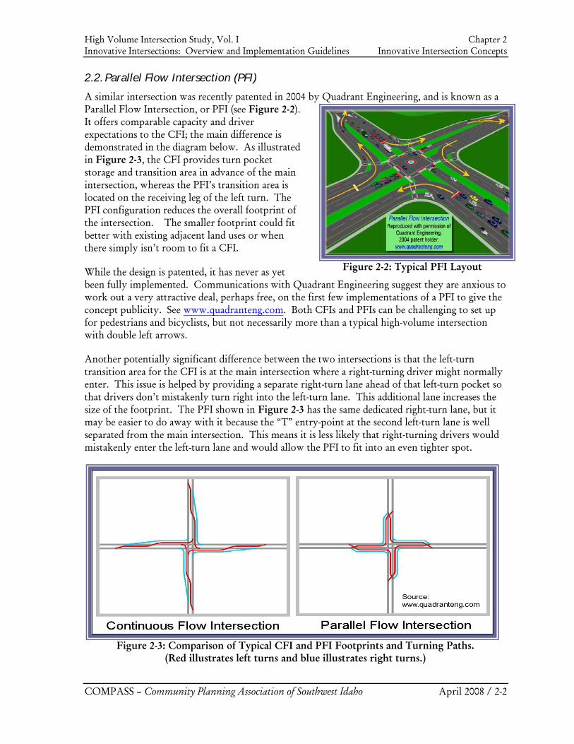
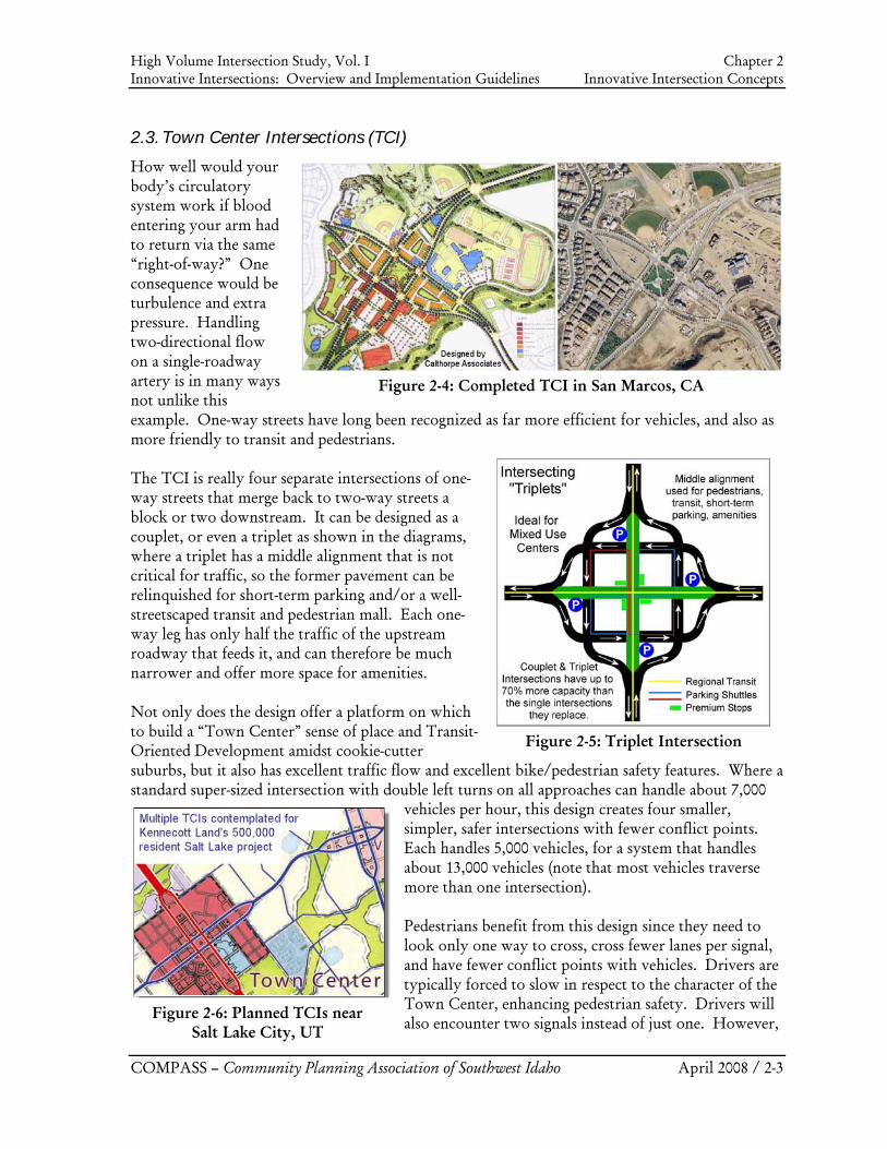
2.2. Parallel Flow Intersection (PFI)
A similar intersection was recently patented in 2004 by Quadrant Engineering, and is known as a Parallel Flow Intersection, or PFI (see Figure 2-2). It offers comparable capacity and driver expectations to the CFI; the main difference is demonstrated in the diagram below. As illustrated in Figure 2-3, the CFI provides turn pocket storage and transition area in advance of the main intersection, whereas the PFI’s transition area is located on the receiving leg of the left turn. The PFI configuration reduces the overall footprint of the intersection. The smaller footprint could fit better with existing adjacent land uses or when there simply isn’t room to fit a CFI. While the design is patented, it has never as yet been fully implemented. Communications with Quadrant Engineering suggest they are anxious to work out a very attractive deal, perhaps free, on the first few implementations of a PFI to give the concept publicity. See www.quadranteng.com. Both CFIs and PFIs can be challenging to set up for pedestrians and bicyclists, but not necessarily more than a typical high-volume intersection with double left arrows. Another potentially significant difference between the two intersections is that the left-turn transition area for the CFI is at the main intersection where a right-turning driver might normally enter. This issue is helped by providing a separate right-turn lane ahead of that left-turn pocket so that drivers don’t mistakenly turn right into the left-turn lane. This additional lane increases the size of the footprint. The PFI shown in Figure 2-3 has the same dedicated right-turn lane, but it may be easier to do away with it because the “T” entry-point at the second left-turn lane is well separated from the main intersection. This means it is less likely that right-turning drivers would mistakenly enter the left-turn lane and would allow the PFI to fit into an even tighter spot.
Figure 2-2: Typical PFI Layout
Figure 2-3: Comparison of Typical CFI and PFI Footprints and Turning Paths.
(Red illustrates left turns and blue illustrates right turns.)
High Volume Intersection Study, Vol. I Chapter 2 Innovative Intersections: Overview and Implementation Guidelines Innovative Intersection Concepts
COMPASS – Community Planning Association of Southwest Idaho April 2008 / 2-3
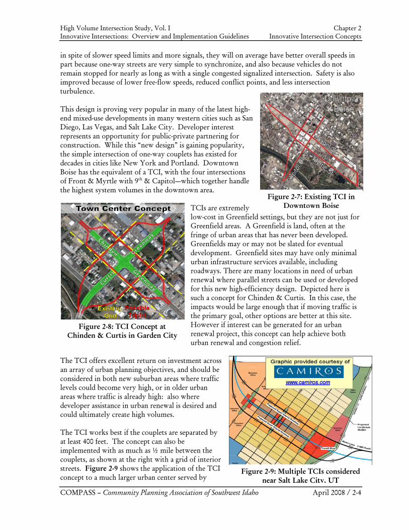
Figure 2-4: Completed TCI in San Marcos, CA
Figure 2-5: Triplet Intersection
Figure 2-6: Planned TCIs near Salt Lake City, UT
2.3. Town Center Intersections (TCI)
How well would your body’s circulatory system work if blood entering your arm had to return via the same “right-of-way?” One consequence would be turbulence and extra pressure. Handling two-directional flow on a single-roadway artery is in many ways not unlike this example. One-way streets have long been recognized as far more efficient for vehicles, and also as more friendly to transit and pedestrians. The TCI is really four separate intersections of one-way streets that merge back to two-way streets a block or two downstream. It can be designed as a couplet, or even a triplet as shown in the diagrams, where a triplet has a middle alignment that is not critical for traffic, so the former pavement can be relinquished for short-term parking and/or a well-streetscaped transit and pedestrian mall. Each one-way leg has only half the traffic of the upstream roadway that feeds it, and can therefore be much narrower and offer more space for amenities. Not only does the design offer a platform on which to build a “Town Center” sense of place and Transit-Oriented Development amidst cookie-cutter suburbs, but it also has excellent traffic flow and excellent bike/pedestrian safety features. Where a standard super-sized intersection with double left turns on all approaches can handle about 7,000
vehicles per hour, this design creates four smaller, simpler, safer intersections with fewer conflict points. Each handles 5,000 vehicles, for a system that handles about 13,000 vehicles (note that most vehicles traverse more than one intersection). Pedestrians benefit from this design since they need to look only one way to cross, cross fewer lanes per signal, and have fewer conflict points with vehicles. Drivers are typically forced to slow in respect to the character of the Town Center, enhancing pedestrian safety. Drivers will also encounter two signals instead of just one. However,
High Volume Intersection Study, Vol. I Chapter 2 Innovative Intersections: Overview and Implementation Guidelines Innovative Intersection Concepts
COMPASS – Community Planning Association of Southwest Idaho April 2008 / 2-4
Figure 2-8: TCI Concept at Chinden & Curtis in Garden City
Figure 2-7: Existing TCI in Downtown Boise
Figure 2-9: Multiple TCIs considered near Salt Lake City, UT
in spite of slower speed limits and more signals, they will on average have better overall speeds in part because one-way streets are very simple to synchronize, and also because vehicles do not remain stopped for nearly as long as with a single congested signalized intersection. Safety is also improved because of lower free-flow speeds, reduced conflict points, and less intersection turbulence. This design is proving very popular in many of the latest high-end mixed-use developments in many western cities such as San Diego, Las Vegas, and Salt Lake City. Developer interest represents an opportunity for public-private partnering for construction. While this “new design” is gaining popularity, the simple intersection of one-way couplets has existed for decades in cities like New York and Portland. Downtown Boise has the equivalent of a TCI, with the four intersections of Front & Myrtle with 9th & Capitol—which together handle the highest system volumes in the downtown area.
TCIs are extremely low-cost in Greenfield settings, but they are not just for Greenfield areas. A Greenfield is land, often at the fringe of urban areas that has never been developed. Greenfields may or may not be slated for eventual development. Greenfield sites may have only minimal urban infrastructure services available, including roadways. There are many locations in need of urban renewal where parallel streets can be used or developed for this new high-efficiency design. Depicted here is such a concept for Chinden & Curtis. In this case, the impacts would be large enough that if moving traffic is the primary goal, other options are better at this site. However if interest can be generated for an urban renewal project, this concept can help achieve both urban renewal and congestion relief.
The TCI offers excellent return on investment across an array of urban planning objectives, and should be considered in both new suburban areas where traffic levels could become very high, or in older urban areas where traffic is already high: also where developer assistance in urban renewal is desired and could ultimately create high volumes. The TCI works best if the couplets are separated by at least 400 feet. The concept can also be implemented with as much as ½ mile between the couplets, as shown at the right with a grid of interior streets. Figure 2-9 shows the application of the TCI concept to a much larger urban center served by
High Volume Intersection Study, Vol. I Chapter 2 Innovative Intersections: Overview and Implementation Guidelines Innovative Intersection Concepts
COMPASS – Community Planning Association of Southwest Idaho April 2008 / 2-5
Figure 2-10: Existing Triplet in Denver
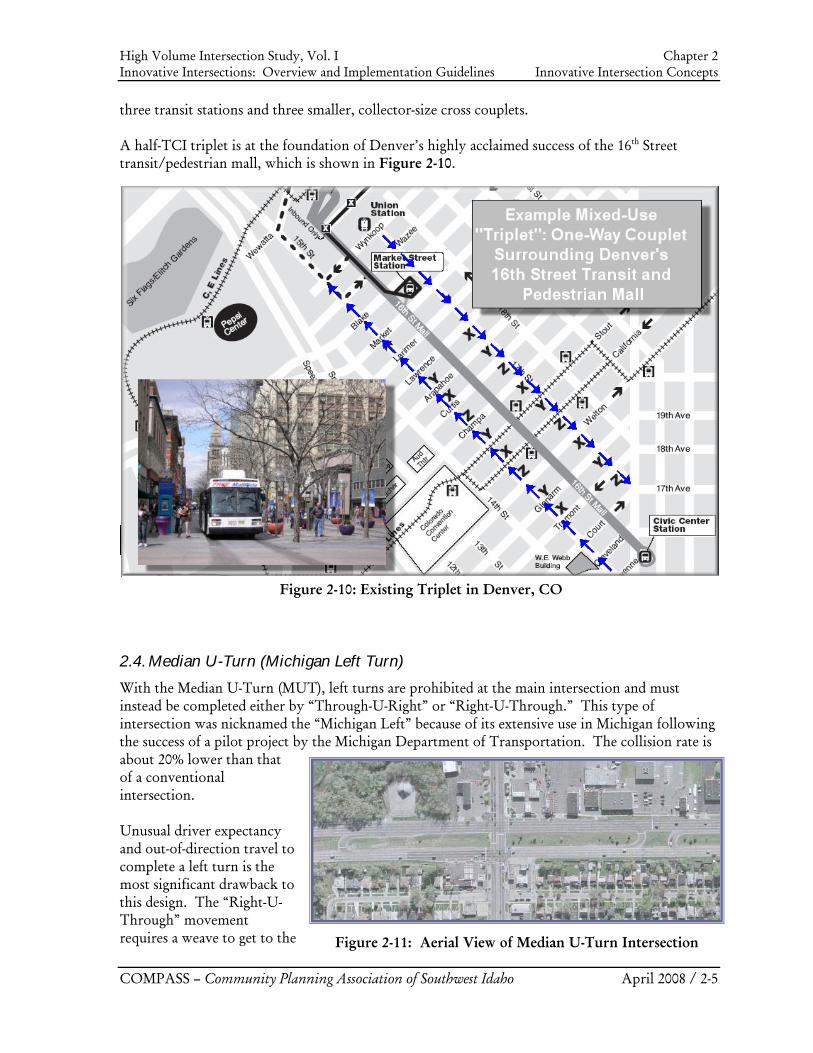
Figure 2-10: Existing Triplet in Denver, CO
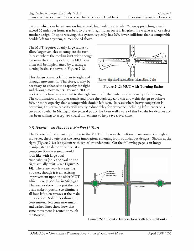
Figure 2-11: Aerial View of Median U-Turn Intersection
three transit stations and three smaller, collector-size cross couplets. A half-TCI triplet is at the foundation of Denver’s highly acclaimed success of the 16th Street transit/pedestrian mall, which is shown in Figure 2-10.
2.4. Median U-Turn (Michigan Left Turn)
With the Median U-Turn (MUT), left turns are prohibited at the main intersection and must instead be completed either by “Through-U-Right” or “Right-U-Through.” This type of intersection was nicknamed the “Michigan Left” because of its extensive use in Michigan following the success of a pilot project by the Michigan Department of Transportation. The collision rate is about 20% lower than that of a conventional intersection. Unusual driver expectancy and out-of-direction travel to complete a left turn is the most significant drawback to this design. The “Right-U-Through” movement requires a weave to get to the
High Volume Intersection Study, Vol. I Chapter 2 Innovative Intersections: Overview and Implementation Guidelines Innovative Intersection Concepts
COMPASS – Community Planning Association of Southwest Idaho April 2008 / 2-6
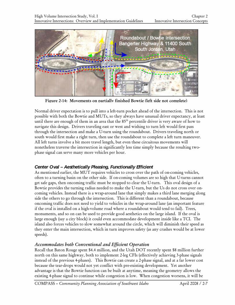
Figure 2-12: MUT with Turning Basins
U-turn, which can be an issue on high-speed, high volume arterials. When approaching speeds exceed 50 miles per hour, it is best to prevent right turns on red, lengthen the weave area, or select another design. In spite weaving, this system typically has 20% fewer collisions than a comparable double left-turn system, as mentioned above. The MUT requires a fairly large radius to allow larger vehicles to complete the turn. In cases where the median isn’t wide enough to create the turning radius, the MUT can often still be implemented by creating a turning basin, as shown in Figure 2-12. This design converts left turns to right and through movements. Therefore, it may be necessary to enhance the capacity for right and through movements. Former left-turn pockets can often be converted to through lanes to further enhance the capacity of this design. The combination of simpler signals and more through capacity can allow this design to achieve 50% or more capacity than a comparable double left-turn. In cases where heavy congestion is occurring, this extra capacity will greatly reduce delay for everyone, including left-turners on a circuitous path. In Michigan, the general public has been well aware of this benefit for decades and has been willing to accept awkward movements to help save travel time.
2.5. Bowtie – an Enhanced Median U-Turn
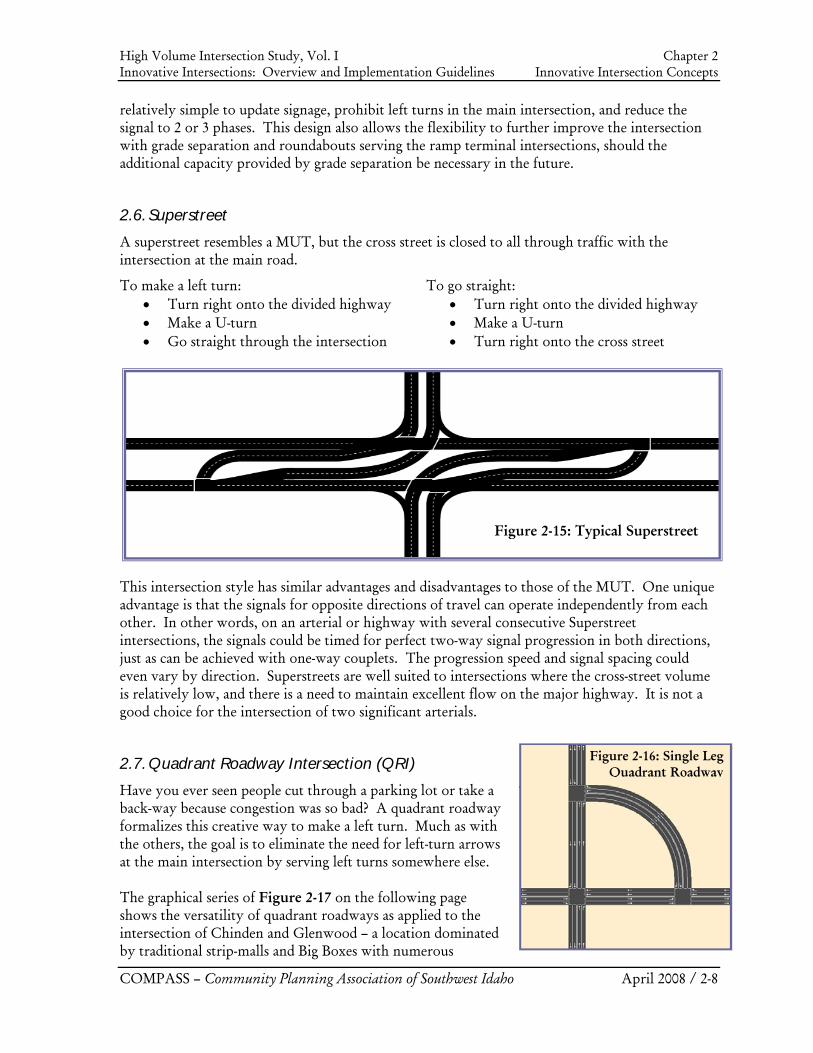
The Bowtie is fundamentally similar to the MUT in the way that left turns are routed through it. However, the Bowtie uses the latest innovations emerging from roundabout designs. Shown at the right (Figure 2-13) is a system with typical roundabouts. On the following page is an image manipulated to demonstrate what a complete Bowtie system would look like with large oval roundabouts (only the oval on the right actually exists – see Figure 2-14). There are very few existing Bowties, though it is an exciting improvement upon the older MUT which is very popular in Michigan. The arrows show how just the two ovals make it possible to eliminate all four left-turn arrows at the main intersection. Solid lines show the conventional left turn movement, and dashed lines show how that same movement is routed through the Bowtie.
Figure 2-13: Bowtie Intersection with Roundabouts
High Volume Intersection Study, Vol. I Chapter 2 Innovative Intersections: Overview and Implementation Guidelines Innovative Intersection Concepts
COMPASS – Community Planning Association of Southwest Idaho April 2008 / 2-7
Normal driver expectation is to pull into a left-turn pocket ahead of the intersection. This is not possible with both the Bowtie and MUTs, so they always have unusual driver expectancy, at least until there are enough of them in an area that the 85th percentile driver is very aware of how to navigate this design. Drivers traveling east or west and wishing to turn left would first pass through the intersection and make a U-turn using the roundabout. Drivers traveling north or south would first make a right turn, then use the roundabout to complete a left turn maneuver. All left turns involve a bit more travel length, but even these circuitous movements will nonetheless traverse the intersection in significantly less time simply because the resulting two-phase signal can serve many more vehicles per hour.
Center Oval – Aesthetically Pleasing, Functionally Efficient As mentioned earlier, the MUT requires vehicles to cross over the path of on-coming vehicles, often to a turning basin on the other side. If on-coming volumes are so high that U-turns cannot get safe gaps, then oncoming traffic must be stopped to clear the U-turn. This oval design of a Bowtie provides the turning radius needed to make the U-turn, but the Us do not cross over on-coming vehicles. Instead there is a wrap-around lane that simply makes a third lane merging along side the others to go through the intersection. This is different than a roundabout, because oncoming traffic does not need to yield to vehicles in the wrap-around lane (an important feature if the oval is installed on a high-volume road where a roundabout would tend to fail). Trees, monuments, and so on can be used to provide good aesthetics on the large island. If the oval is large enough (say a city block) it could even accommodate development inside like a TCI. The island also forces vehicles to slow somewhat around the circle, which will diminish their speed as they enter the main intersection, which in turn improves safety (as any crashes would be at lower speeds). Accommodates both Conventional and Efficient Operation Recall that Baton Rouge spent $4.4 million, and the Utah DOT recently spent $8 million further north on this same highway, both to implement 2-leg CFIs (effectively achieving 3-phase signals instead of the previous 4-phases). This Bowtie can create a 2-phase signal, and at a far lower cost because the tear-drops would not yet conflict with pre-existing development. Yet another advantage is that the Bowtie function can be built at anytime, meaning the geometry allows the existing 4-phase signal to continue while congestion is low. When congestion worsens, it will be
Figure 2-14: Movements on partially finished Bowtie (left side not complete)
High Volume Intersection Study, Vol. I Chapter 2 Innovative Intersections: Overview and Implementation Guidelines Innovative Intersection Concepts
COMPASS – Community Planning Association of Southwest Idaho April 2008 / 2-8
Figure 2-16: Single Leg Quadrant Roadway
relatively simple to update signage, prohibit left turns in the main intersection, and reduce the signal to 2 or 3 phases. This design also allows the flexibility to further improve the intersection with grade separation and roundabouts serving the ramp terminal intersections, should the additional capacity provided by grade separation be necessary in the future.
2.6. Superstreet
A superstreet resembles a MUT, but the cross street is closed to all through traffic with the intersection at the main road.
To make a left turn: • Turn right onto the divided highway • Make a U-turn • Go straight through the intersection
To go straight: • Turn right onto the divided highway • Make a U-turn • Turn right onto the cross street
This intersection style has similar advantages and disadvantages to those of the MUT. One unique advantage is that the signals for opposite directions of travel can operate independently from each other. In other words, on an arterial or highway with several consecutive Superstreet intersections, the signals could be timed for perfect two-way signal progression in both directions, just as can be achieved with one-way couplets. The progression speed and signal spacing could even vary by direction. Superstreets are well suited to intersections where the cross-street volume is relatively low, and there is a need to maintain excellent flow on the major highway. It is not a good choice for the intersection of two significant arterials.
2.7. Quadrant Roadway Intersection (QRI)
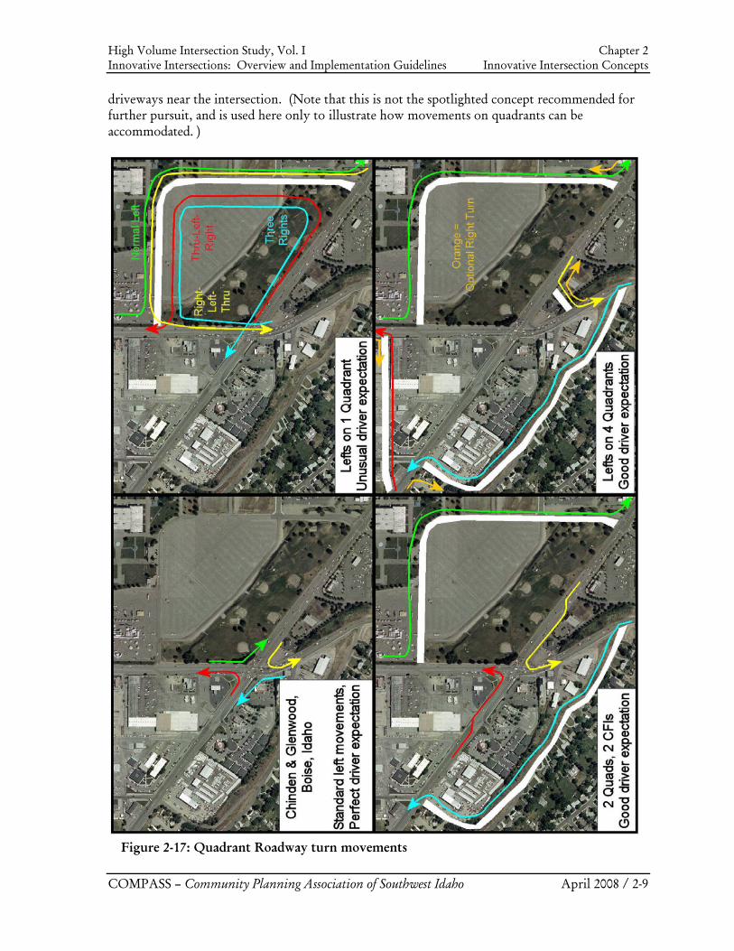
Have you ever seen people cut through a parking lot or take a back-way because congestion was so bad? A quadrant roadway formalizes this creative way to make a left turn. Much as with the others, the goal is to eliminate the need for left-turn arrows at the main intersection by serving left turns somewhere else. The graphical series of Figure 2-17 on the following page shows the versatility of quadrant roadways as applied to the intersection of Chinden and Glenwood – a location dominated by traditional strip-malls and Big Boxes with numerous
Figure 2-15: Typical Superstreet
High Volume Intersection Study, Vol. I Chapter 2 Innovative Intersections: Overview and Implementation Guidelines Innovative Intersection Concepts
COMPASS – Community Planning Association of Southwest Idaho April 2008 / 2-9
driveways near the intersection. (Note that this is not the spotlighted concept recommended for further pursuit, and is used here only to illustrate how movements on quadrants can be accommodated. )
Figure 2-17: Quadrant Roadway turn movements
High Volume Intersection Study, Vol. I Chapter 2 Innovative Intersections: Overview and Implementation Guidelines Innovative Intersection Concepts
COMPASS – Community Planning Association of Southwest Idaho April 2008 / 2-10
There are innumerable urban settings across America where intersection land uses are very similar to this site. There are often very simple ways to create a QRI by using existing “back-way” streets, or by developing such streets through existing parking lots. Traits of a Single Quadrant Roadway It is possible to eliminate all four left turns from the main intersection with just one quadrant roadway. The routing for such is shown in the upper-right image in the series (Figure 2-16). As with a CFI, SB to EB makes a normal left, but in a pocket well ahead of the intersection (green). Like a MUT, EB to NB goes “Through-left-right” (red). WB to SB is similar as a “Right-left-through” (yellow). Finally, NB to WB does what some delivery drivers are told to do to make a faster left: “three right turns make a left” (blue). Confusing? On paper, yes. In the beginning, yes. But people get used to it, and they may well prefer it if the alternatives invoke too much delay time or are more expensive. It is important to have good signing. It is also possible that the quadrant roadway itself will become unacceptably busy handling all four movements. Traits of Two Roadways in Opposite Quadrants If just two roadways in opposite quadrants can be created, then a 4-phase signal can be dropped to three phases without compromising driver expectation (by accommodating two left turns at mid-block locations, and the other two as standard double left turns at the main intersection). The image in the lower-left also shows how the 3-phase signal could further be dropped to two phases by using CFIs instead of standard double left turns. All of these allow the quadrant concept to move from unusual driver expectancy to much better if not very good expectancy. It also greatly reduces the pressure on any single quadrant, which may be operationally as well as politically important. Traits of Four Quadrant Roadways Normally in a developed setting, it will be very difficult to identify acceptable alignments for four quadrant roadways. However, if affordable and politically acceptable alignments can be found, the combination of four roadways has several very attractive properties. First, movements are very similar to a 4-leg CFI, but vehicles travel behind development instead of in front of it. Where all movements are made from a left pocket ahead of the main intersection, this achieves near-perfect driver expectancy with no out-of-direction travel. Four roadways also have much higher overall capacity because all left turns and many or even all right turns can be completely removed from the main intersection (where fewer quadrants converts former left turns to easier-to-manage through and right-turn movements). Four and even two roadways also have much in common with TCIs. A 4-leg CFI requires a massive footprint at the main intersection, major restrictions on adjacent access, and is somewhat intimidating to pedestrians. Four roadways allow for the most minimal footprint at the main intersection because with left and right turns removed, that former pavement can be used for aesthetic and pedestrian enhancements. Property access is much easier also, because access is easily provided from each quadrant roadway. The system creates “four blocks” almost like a mini-downtown. It has far higher capacity, excellent access to adjacent properties, and is very pedestrian and transit friendly. All of these features can serve as catalysts for mixed-use urban renewal.
High Volume Intersection Study, Vol. I Chapter 2 Innovative Intersections: Overview and Implementation Guidelines Innovative Intersection Concepts
COMPASS – Community Planning Association of Southwest Idaho April 2008 / 2-11
Figure 2-18: Continuous Green-T
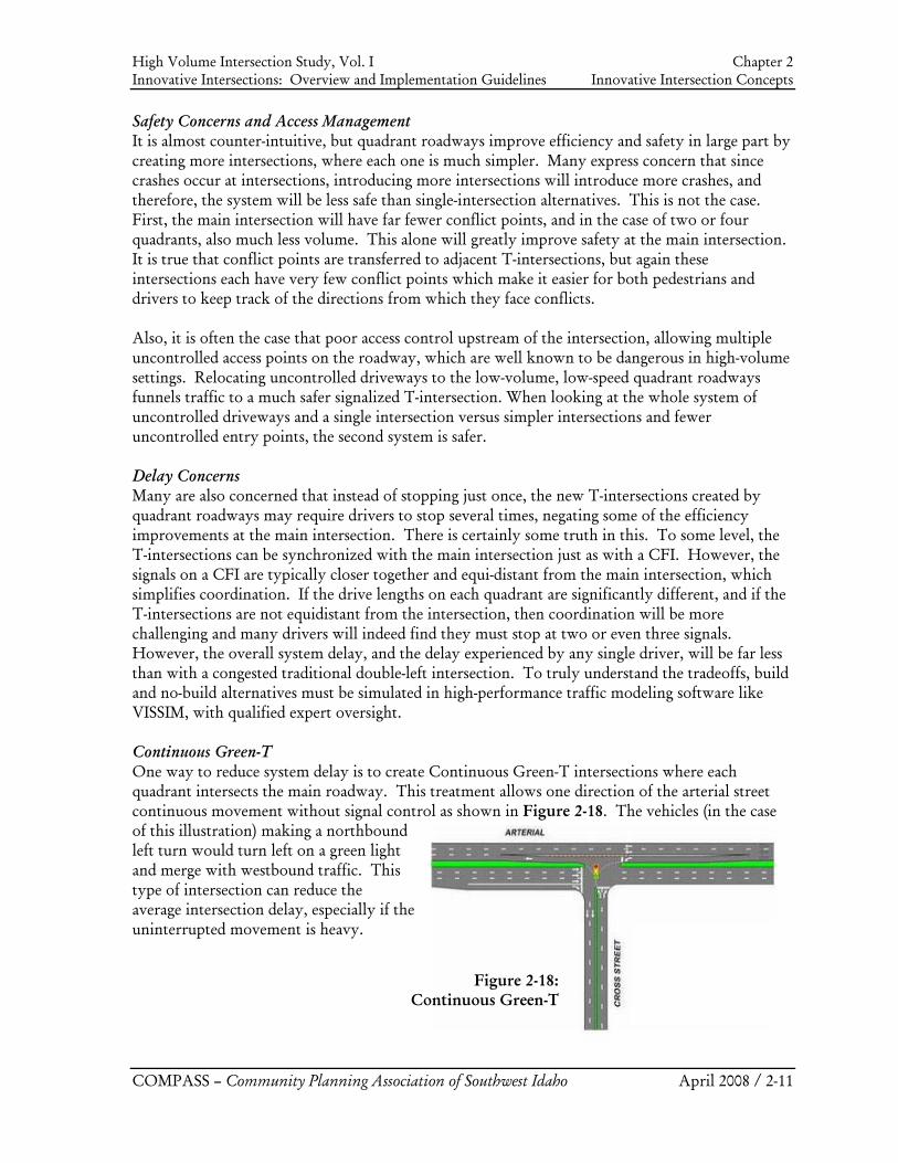
Safety Concerns and Access Management It is almost counter-intuitive, but quadrant roadways improve efficiency and safety in large part by creating more intersections, where each one is much simpler. Many express concern that since crashes occur at intersections, introducing more intersections will introduce more crashes, and therefore, the system will be less safe than single-intersection alternatives. This is not the case. First, the main intersection will have far fewer conflict points, and in the case of two or four quadrants, also much less volume. This alone will greatly improve safety at the main intersection. It is true that conflict points are transferred to adjacent T-intersections, but again these intersections each have very few conflict points which make it easier for both pedestrians and drivers to keep track of the directions from which they face conflicts. Also, it is often the case that poor access control upstream of the intersection, allowing multiple uncontrolled access points on the roadway, which are well known to be dangerous in high-volume settings. Relocating uncontrolled driveways to the low-volume, low-speed quadrant roadways funnels traffic to a much safer signalized T-intersection. When looking at the whole system of uncontrolled driveways and a single intersection versus simpler intersections and fewer uncontrolled entry points, the second system is safer. Delay Concerns Many are also concerned that instead of stopping just once, the new T-intersections created by quadrant roadways may require drivers to stop several times, negating some of the efficiency improvements at the main intersection. There is certainly some truth in this. To some level, the T-intersections can be synchronized with the main intersection just as with a CFI. However, the signals on a CFI are typically closer together and equi-distant from the main intersection, which simplifies coordination. If the drive lengths on each quadrant are significantly different, and if the T-intersections are not equidistant from the intersection, then coordination will be more challenging and many drivers will indeed find they must stop at two or even three signals. However, the overall system delay, and the delay experienced by any single driver, will be far less than with a congested traditional double-left intersection. To truly understand the tradeoffs, build and no-build alternatives must be simulated in high-performance traffic modeling software like VISSIM, with qualified expert oversight. Continuous Green-T One way to reduce system delay is to create Continuous Green-T intersections where each quadrant intersects the main roadway. This treatment allows one direction of the arterial street continuous movement without signal control as shown in Figure 2-18. The vehicles (in the case of this illustration) making a northbound left turn would turn left on a green light and merge with westbound traffic. This type of intersection can reduce the average intersection delay, especially if the uninterrupted movement is heavy.
High Volume Intersection Study, Vol. I Chapter 2 Innovative Intersections: Overview and Implementation Guidelines Innovative Intersection Concepts
COMPASS – Community Planning Association of Southwest Idaho April 2008 / 2-12
Figure 2-19: Jughandle turn movements
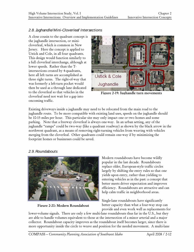
Figure 2-20: Modern Roundabout
2.8. Jughandle/Mini-Cloverleaf Intersections
A close cousin to the quadrant concept is the jughandle intersection, or mini-cloverleaf, which is common in New Jersey. Here the concept is applied to Ustick and Cole, in all four quadrants. This design would function similarly to a full cloverleaf interchange, although at lower speeds. Rather than the T-intersections created by 4-quadrants, here all left turns are accomplished as three right turns. The right-of-way that was formerly a left-turn pocket would then be used as a through lane dedicated to the cloverleaf so that vehicles in the cloverleaf need not wait for a gap into oncoming traffic. Existing driveways inside a jughandle may need to be relocated from the main road to the jughandle route. To be more compatible with existing land uses, speeds on the jughandle should be 10-15 miles per hour. This particular site may only impact one or two homes and some parking. Note that a freeway cloverleaf is always one-way. In an urban setting, any of the jughandle “ramps” could be two-way (like a quadrant roadway) as shown by the black arrow in the northwest quadrant, as a means of removing right-turning vehicles from weaving with vehicles merging from the cloverleaf. Other quadrants could remain one-way if by minimizing the footprint homes or businesses could be saved.
2.9. Roundabouts
Modern roundabouts have become wildly popular in the last decade. Roundabouts replace older, European-style traffic circles largely by shifting the entry rules so that one yields upon entry, rather than yielding to entering vehicles as in the past: a concept that better meets driver expectation and improves efficiency. Roundabouts are attractive and can help calm traffic in neighborhood areas. Single-lane roundabouts have significantly better capacity than what a four-way stop can provide and even work well as replacements for
lower-volume signals. There are only a few multi-lane roundabouts thus far in the U.S., but they are able to handle volumes equivalent to those at the intersection of a minor arterial and a major collector. Roundabout capacity improves as the roundabout itself becomes larger, since there is more opportunity inside the circle to weave and position for the needed movement. A multi-lane
High Volume Intersection Study, Vol. I Chapter 2 Innovative Intersections: Overview and Implementation Guidelines Innovative Intersection Concepts
COMPASS – Community Planning Association of Southwest Idaho April 2008 / 2-13
Figure 2-21: Center Left-Turn Overpass
roundabout has lower overall capacity than a traditional double-left intersection, unless the roundabout is extremely large to create more opportunity inside the circle to weave and position for the needed movement. For additional information on roundabouts, please visit www.roundaboutsusa.com.
2.10. Grade-Separated Innovative Designs (Arterial Interchanges)
Like at-grade intersections, grade-separated solutions can be designed to fit into narrow rights-of-way and non-freeway settings. These are unlike designs used for freeways which create incredible capacity in one direction, but do little for congested cross traffic. Designs that create a free movement often encourage higher speeds, have more access restrictions, and are often overly large and out of context as candidates to upgrade an at-grade urban intersection. They also do little for congested cross traffic and often create more capacity on the free movement than neighboring intersections can supply. However many arterial interchange designs distribute the benefits of grade separation across all movements more evenly—an attractive feature when volumes on both roadways are very high, and very similar. Disadvantages common to all arterial interchanges include the need for expensive and visually obstructing structures and challenging access to adjacent land uses. Although no grade-separated designs are spotlighted or recommended in the Concept Layout Report, there will be locations and conditions in the future where an arterial interchange may be the preferred solution. The intersection treatments in this section are intended to introduce additional improvement possibilities to further develop the “toolbox” of options, providing information about possible solutions in a variety of situations. Two arterial interchanges that fit with typical driver expectations when navigating an arterial street are the center left-turn overpass and the echelon interchange. In both of these, all movements are still subject to signals, to which one might respond “Why did we build a structure?” At very high-volume intersections in built-up areas, where no at-grade innovative intersection designs have sufficient capacity, these arterial interchanges provide a higher-capacity option that may fit within right-of-way constraints and cost considerably less than a freeway-style interchange.
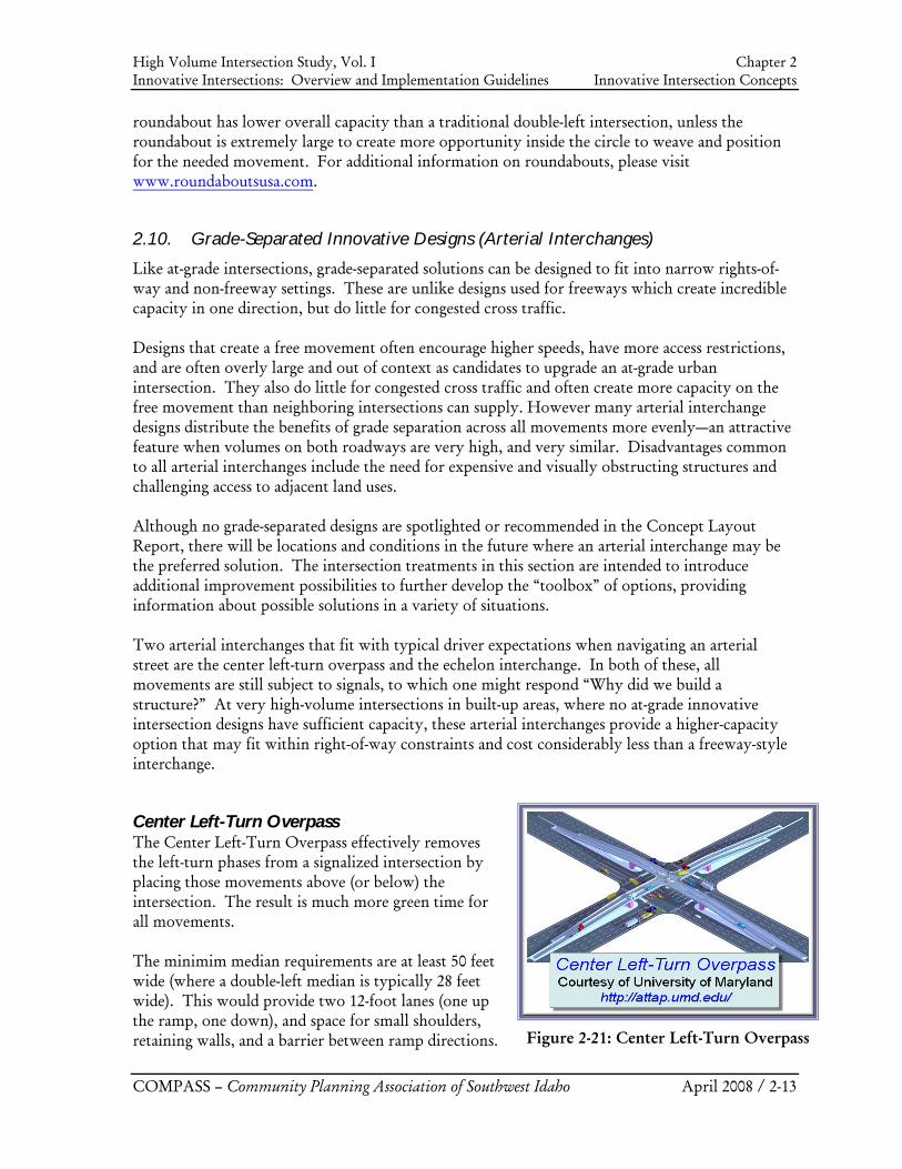
Center Left-Turn Overpass The Center Left-Turn Overpass effectively removes the left-turn phases from a signalized intersection by placing those movements above (or below) the intersection. The result is much more green time for all movements. The minimim median requirements are at least 50 feet wide (where a double-left median is typically 28 feet wide). This would provide two 12-foot lanes (one up the ramp, one down), and space for small shoulders, retaining walls, and a barrier between ramp directions.
High Volume Intersection Study, Vol. I Chapter 2 Innovative Intersections: Overview and Implementation Guidelines Innovative Intersection Concepts
COMPASS – Community Planning Association of Southwest Idaho April 2008 / 2-14
Figure 2-23: CFI Diamond
This ramp design concept is similar to T-ramp designs on high-occupancy vehicle facilities. It is believed that none have yet been built.
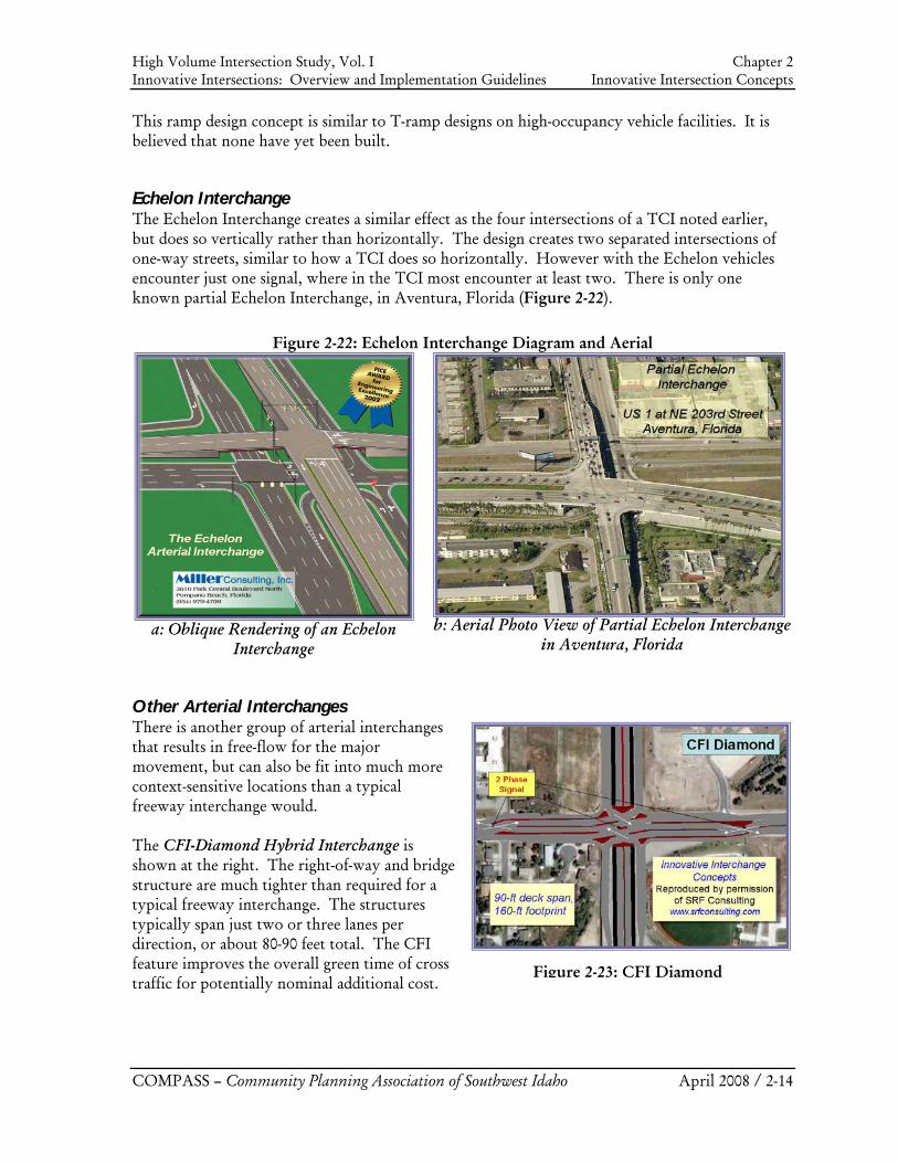
Echelon Interchange The Echelon Interchange creates a similar effect as the four intersections of a TCI noted earlier, but does so vertically rather than horizontally. The design creates two separated intersections of one-way streets, similar to how a TCI does so horizontally. However with the Echelon vehicles encounter just one signal, where in the TCI most encounter at least two. There is only one known partial Echelon Interchange, in Aventura, Florida (Figure 2-22).
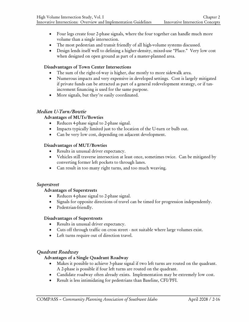
Other Arterial Interchanges There is another group of arterial interchanges that results in free-flow for the major movement, but can also be fit into much more context-sensitive locations than a typical freeway interchange would. The CFI-Diamond Hybrid Interchange is shown at the right. The right-of-way and bridge structure are much tighter than required for a typical freeway interchange. The structures typically span just two or three lanes per direction, or about 80-90 feet total. The CFI feature improves the overall green time of cross traffic for potentially nominal additional cost.
Figure 2-22: Echelon Interchange Diagram and Aerial
a: Oblique Rendering of an Echelon
Interchange
b: Aerial Photo View of Partial Echelon Interchange
in Aventura, Florida
High VInnov
COM
Figu
2.11.
ListedrelativapproAddit
At-G Cont
A
D
Town
A
Volume Intersvative Intersect
MPASS – Com
re 2-24: Dive
. Summa
d below are thve to automooaches (an inetional Materia
Grade Inters
tinuous FlowAdvantages o
• Two le• Four le• Good d• Operat
build w
Disadvantage• Require
future g• Safe for
friendly• Can be
n Center Advantages o
• Two le
section Study, tions: Overvie
mmunity Plan
erging Diam
ry of Comp
he more signobile movemeefficient, 4-phals.
sections
w/Parallel Fof CFIs/PFIsgs always ach
egs always achdriver expectationally, CFIswithin existin
es of CFIs/Pes a consideragrade separatr pedestrians,y.” expensive if
of TCIs gs create two
Vol. I ew and Implem
nning Associat
mond
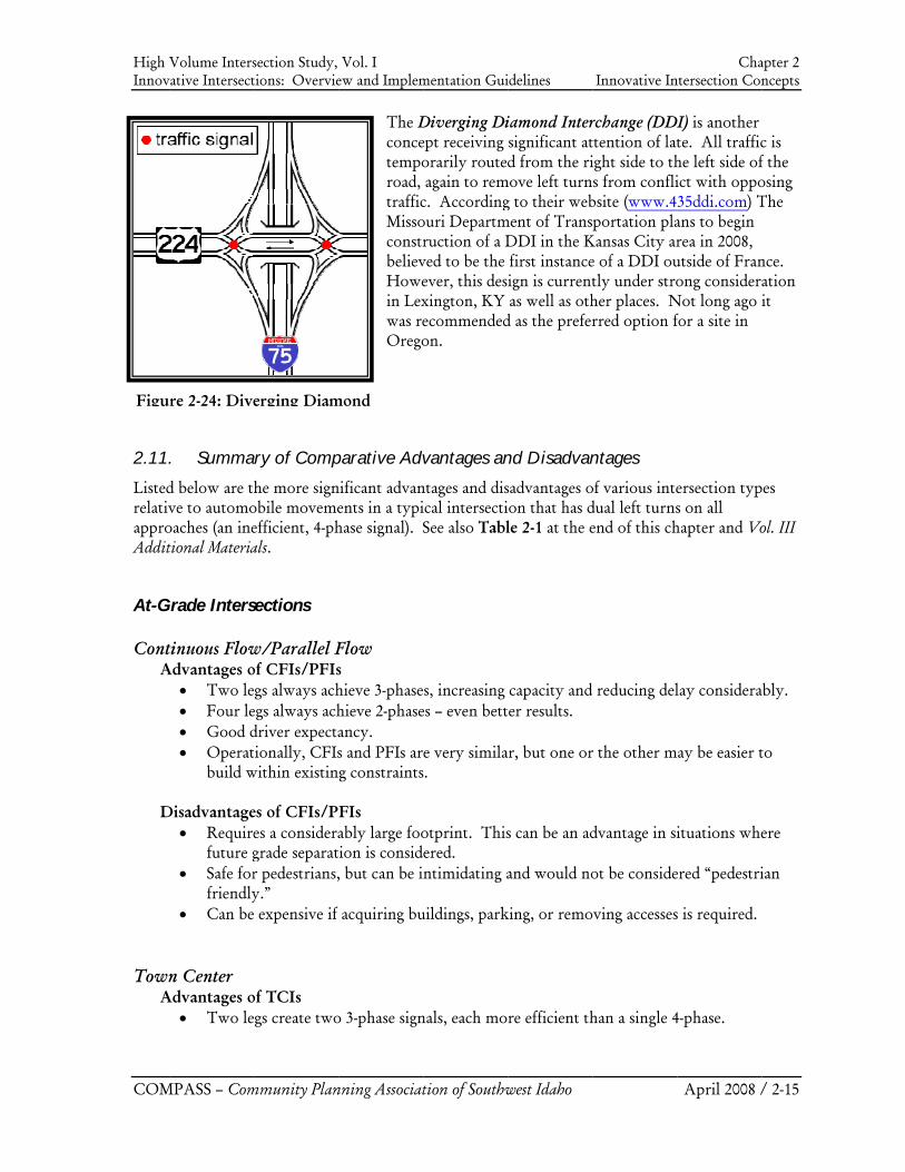
The Dconcetemporoad, trafficMissoconstrbelievHowein Lexwas reOrego
parative Adv
nificant advanents in a typihase signal). S
Flow s hieve 3-phasehieve 2-phaseancy. s and PFIs arg constraints
FIs ably large fooion is consid, but can be i
acquiring bu
o 3-phase sign
mentation Gui
tion of Southw
Diverging Diept receiving orarily routed again to remc. Accordingouri Departmruction of a Dved to be the ever, this desxington, KY ecommendedon.
vantages an
ntages and disical intersectiSee also Tabl
s, increasing es – even bett
e very similas.
otprint. Thisered. ntimidating a
uildings, park
nals, each mo
idelines
west Idaho
iamond Intersignificant atd from the ri
move left turng to their web
ment of TransDDI in the K first instanceign is current as well as othd as the prefer
nd Disadvan
sadvantages oon that has dle 2-1 at the e
capacity and er results.
ar, but one or
s can be an ad
and would no
king, or remo
re efficient th
Innovative In
rchange (DDIttention of latight side to ths from confli
bsite (www.4portation pla
Kansas City are of a DDI outly under stroher places. Nrred option f
ntages
of various intedual left turnsend of this ch
reducing del
r the other m
dvantage in si
ot be conside
ving accesses
han a single 4
Chantersection Con
April 2008 /
DI) is another te. All traffiche left side ofict with oppo35ddi.com) Tans to begin rea in 2008, utside of Franong considera
Not long ago ifor a site in
ersection typs on all hapter and Vo
lay considera
ay be easier t
ituations whe
ered “pedestri
s is required.
4-phase.
apter 2 ncepts
/ 2-15
c is f the osing The
nce. ation it
pes
ol. III
ably.
to
ere
ian
High Volume Intersection Study, Vol. I Chapter 2 Innovative Intersections: Overview and Implementation Guidelines Innovative Intersection Concepts
COMPASS – Community Planning Association of Southwest Idaho April 2008 / 2-16
• Four legs create four 2-phase signals, where the four together can handle much more volume than a single intersection.
• The most pedestrian and transit friendly of all high-volume systems discussed. • Design lends itself well to defining a higher-density, mixed-use “Place.” Very low cost
when designed on open ground as part of a master-planned area.
Disadvantages of Town Center Intersections • The sum of the right-of-way is higher, due mostly to more sidewalk area. • Numerous impacts and very expensive in developed settings. Cost is largely mitigated
if private funds can be attracted as part of a general redevelopment strategy, or if tax-increment financing is used for the same purpose.
• More signals, but they’re easily coordinated. Median U-Turn/Bowtie
Advantages of MUTs/Bowties • Reduces 4-phase signal to 2-phase signal. • Impacts typically limited just to the location of the U-turn or bulb out. • Can be very low cost, depending on adjacent development.
Disadvantages of MUT/Bowties
• Results in unusual driver expectancy. • Vehicles still traverse intersection at least once, sometimes twice. Can be mitigated by
converting former left pockets to through lanes. • Can result in too many right turns, and too much weaving.
Superstreet
Advantages of Superstreets • Reduces 4-phase signal to 2-phase signal. • Signals for opposite directions of travel can be timed for progression independently. • Pedestrian-friendly.
Disadvantages of Superstreets
• Results in unusual driver expectancy. • Cuts off through traffic on cross street - not suitable where large volumes exist. • Left turns require out of direction travel.
Quadrant Roadway
Advantages of a Single Quadrant Roadway • Makes it possible to achieve 3-phase signal if two left turns are routed on the quadrant.
A 2-phase is possible if four left turns are routed on the quadrant. • Candidate roadway often already exists. Implementation may be extremely low cost. • Result is less intimidating for pedestrians than Baseline, CFI/PFI.
High Volume Intersection Study, Vol. I Chapter 2 Innovative Intersections: Overview and Implementation Guidelines Innovative Intersection Concepts
COMPASS – Community Planning Association of Southwest Idaho April 2008 / 2-17
Disadvantages of a Single Quadrant Roadway • Routing all four left turns onto the roadway creates unusual driver expectancy.
However the public may prefer to get used to awkward paths if it means they’ll save a lot of time and the implementation cost is low.
• The quadrant roadway will itself become very busy if it is functioning for all 4-left movements.
• Three of four left-turn paths still require drivers to traverse the main intersection – sometimes twice. Thus left turns are eliminated, but there are more right turns and through movements. The former left-turn lanes may be used as through lanes to handle higher through volume.
Advantages of Multiple Quadrant Roadways
• Provides great access to adjacent properties, very good pedestrian and transit environment.
• Each quadrant handles less volume. • 4-quadrant intersections have very good driver expectancy – all approaches can turn left
ahead of intersection. No circuitous paths. • With four quadrants, left turns never enter the main intersection – making four
quadrants among the highest overall capacity.
Disadvantages of Multiple Quadrant Roadways • Can be expensive to find alignments for multiple quadrants. • Introduces T-intersections – more signals that are more challenging to coordinate than
some others, such as a CFI. • Mitigate by making Continuous Green-Ts.
Jughandle/Mini-Cloverleaf
Advantages of Jughandles/Mini-Cloverleafs • Narrower right-of-way requirements on the major street. • Reduces number of signal phases. • Conflict points are reduced and spread out.
Disadvantages of Jughandles/Mini-Cloverleafs
• Indirect left turns and potential driver confusion. • Driver disregard of left-turn prohibition. • Additional right-of-way required for jughandle ramp.
Roundabout
Advantages of Multi-Lane Roundabouts • Reduced number of conflict points. • Lower operational speeds decreases accident occurrence and severity. • Aesthetically pleasing.
High Volume Intersection Study, Vol. I Chapter 2 Innovative Intersections: Overview and Implementation Guidelines Innovative Intersection Concepts
COMPASS – Community Planning Association of Southwest Idaho April 2008 / 2-18
Disadvantages of Multi-Lane Roundabouts • Driver unfamiliarity. • May be difficult for visually impaired pedestrians. • No preemption for emergency vehicles. • Lower overall capacity than a conventional intersection – not recommended for
intersection volumes expected to exceed 4,000 vehicles per hour.
Arterial Interchanges Listed below are the more significant advantages and disadvantages of various grade-separated intersection types relative to a typical tight-diamond interchange. Center Left-Turn
Advantages of Center Left-turn Overpasses • Preserves access to adjacent properties. • Pedestrian-friendly – remove conflicts with left-turn vehicles, shorter wait times. • New capacity shared more evenly between all movements (i.e. more suited to
intersecting arterials of similar volumes). • All movements subject to stop, which discourages high speeds that tend to occur when
one movement is free.
Disadvantages of Center Left-turn Overpasses • Snow/ice removal from overpass. • Provision for U-turns may be difficult. • Potential sight distance issues/visual obstruction. • More expensive to construct (larger and more challenging deck, potentially more in
retaining walls). Echelon
Advantages of Echelon Interchanges • Two efficient 2-phase signals. • Easier for pedestrians than a diamond interchange. • Good land access in two of four quadrants. • New capacity shared more evenly between all movements (i.e. more suited to
intersecting arterials of similar volumes). • All movements subject to stop, which discourages high speeds that tend to occur when
one movement is free.
Disadvantages of Echelon Interchanges • Driver unfamiliarity. • Provision of U-turns requires longer bridge span. • Less appropriate when one roadway has significantly higher volume than the other.
High Volume Intersection Study, Vol. I Chapter 2 Innovative Intersections: Overview and Implementation Guidelines Innovative Intersection Concepts
COMPASS – Community Planning Association of Southwest Idaho April 2008 / 2-19
CFI Diamond/Diverging Diamond Advantages of CFI-Diamond/Diverging Diamond Interchanges (over just a Diamond)
• Improves flow and capacity of cross-street traffic.
Disadvantages of CFI-Diamond/Diverging Diamond Interchanges • Driver unfamiliarity. • Potentially more expensive.
2.12. Intersection Toolbox: What, When, Where, Why
All innovative designs create more “green time” by somehow removing the need for left arrows in the main intersection, leaving the simplest possible signals. They each have additional pros and cons that should be considered by location as noted above. The paragraphs below describe situations when one or the other intersection type may be more appropriate. At the end of the section is a “Toolbox” table (Table 2-1) that compares capacity, costs, and other key attributes to help planners and engineers determine which designs may be appropriate to a given situation. Town Center Intersection – good “Place Making” design that is very compatible with transit and pedestrians. Among the most able to attract developer investment: At any suburban fringe location where place-making is desired and ultimate demand could be far higher than a standard intersection can deliver, TCIs should be a top consideration because: 1) They handle high volumes even at low pedestrian friendly design speeds; 2) It is easier to design architecturally pleasing, transit-oriented “Places” around them; 3) Less stringent access control standards does not degrade the safety or flow as much as with other options; 4) They are extremely affordable – especially if developers construct all or part of the system from a belief the system will enhance access and character for their development. It is also among the best choices to help motivate urban renewal of blighted areas. Quadrant – locations near older retail centers that want to encourage mixed-uses and become more pedestrian friendly: At hundreds of locations it is relatively simple to create quadrant paths behind existing buildings or through parking lots. This also can enhance access to land uses on those quadrants, and like TCIs, spur place-making development if such is desired. Bowties – great for aesthetics and both conventional and unconventional operation: Tear-drop ovals and roundabouts are great for landscaping and flexible enough for 2, 3, or 4-phase signal operation. Can be built as 4-phase (perfect driver expectation); converted later to a 2-phase (less delay, but unusual expectations). CFI/PFI – locations with good existing access control, large setbacks, and where vehicle movement is a higher priority than any other objective: Because of the larger footprint and stricter access controls, they may be easier to upgrade to arterial interchanges. Data from recently opened sites is still emerging, but they are generally performing as anticipated. They have good driver expectation and should be strongly considered at many locations. Roundabouts in lieu of 4-way stops, lower-grade signals: Not recommended as a “regional high volume” intersection. Well proven in last decade to fit nicely with neighborhood-level major collectors. They can be integrated as part of a TCI or modified as a Bowtie for higher efficiency.
High Volume Intersection Study, Vol. I Chapter 2 Innovative Intersections: Overview and Implementation Guidelines Innovative Intersection Concepts
COMPASS – Community Planning Association of Southwest Idaho April 2008 / 2-20
Arterial Interchanges – locations where total volume simply overwhelms other systems: Since at-grade options exist that can provide as much as 75% of the benefit for much less than 75% of the cost, arterial interchanges would be recommended only in unique situations, such as when two roadways are each nearing volumes that can’t be handled otherwise. Opportunity for Transit-ways/HOV: Stakeholders are often reluctant to sacrifice existing lanes on a congested roadway to transit because it will exacerbate existing congestion. These innovative intersection options may open a window to obtain exclusive right-of-way for HOV or transit. By allowing the vehicles currently served by three lanes to have the same or better service in just two lanes it thereby opens a window for transit and HOV to claim the third lane. Lower cost than widening?: Historically lanes have been added to an entire roadway in spite of the utility and development conflicts, when the real problem may have just been inefficient signals. While some designs are costly, it may clear up congestion enough that there is no longer a need to widen an entire road – achieving the desired results with an overall lower cost and with fewer impacts.
High V
olume Intersection Study, V
ol. I C
hapter 2 Innovative Intersections: O
verview and Im
plementation G
uidelines Innovative Intersection C
oncepts C
OM
PASS – C
omm
unity Planning Association of Southw
est Idaho A
pril 2008 / 2-21
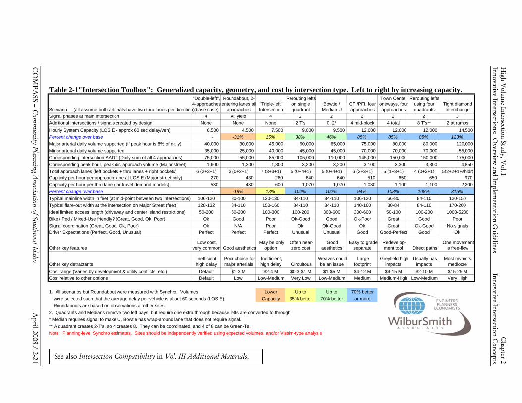
Table 2-1"Intersection Toolbox": Generalized capacity, geometry, and cost by intersection type. Left to right by increasing capacity.
Scenario (all assume both arterials have two thru lanes per direction).
"Double-left", 4-approaches (base case)
Roundabout, 2- entering lanes all
approaches"Triple-left" Intersection
Rerouting lefts on single quadrant
Bowtie / Median U
CFI/PFI, four approaches
Town Center oneways, fourapproaches
Rerouting lefts using four quadrants
Tight diamond Interchange
Signal phases at main intersection 4 All yield 4 2 2 2 2 2 3Additional intersections / signals created by design None None None 2 T's 0, 2* 4 mid-block 4 total 8 T's** 2 at ramps Hourly System Capacity (LOS E - approx 60 sec delay/veh) 6,500 4,500 7,500 9,000 9,500 12,000 12,000 12,000 14,500 Percent change over base - -31% 15% 38% 46% 85% 85% 85% 123% Major arterial daily volume supported (if peak hour is 8% of daily) 40,000 30,000 45,000 60,000 65,000 75,000 80,000 80,000 120,000 Minor arterial daily volume supported 35,000 25,000 40,000 45,000 45,000 70,000 70,000 70,000 55,000 Corresponding intersection AADT (Daily sum of all 4 approaches) 75,000 55,000 85,000 105,000 110,000 145,000 150,000 150,000 175,000 Corresponding peak hour, peak dir. approach volume (Major street) 1,600 1,300 1,800 3,200 3,200 3,100 3,300 3,300 4,850 Total approach lanes (left pockets + thru lanes + right pockets) 6 (2+3+1) 3 (0+2+1) 7 (3+3+1) 5 (0+4+1) 5 (0+4+1) 6 (2+3+1) 5 (1+3+1) 4 (0+3+1) 5(2+2+1+shldr) Capacity per hour per approach lane at LOS E (Major street only) 270 430 260 640 640 510 650 650 970 Capacity per hour per thru lane (for travel demand models) 530 430 600 1,070 1,070 1,030 1,100 1,100 2,200 Percent change over base - -19% 13% 102% 102% 94% 108% 108% 315% Typical mainline width in feet (at mid-point between two intersections) 106-120 80-100 120-130 84-110 84-110 106-120 66-80 84-110 120-150Typical flare-out width at the intersection on Major Street (feet) 128-132 84-110 150-160 84-110 84-110 140-160 80-84 84-110 170-200Ideal limited access length (driveway and center island restrictions) 50-200 50-200 100-300 100-200 300-600 300-600 50-100 100-200 1000-5280 Bike / Ped / Mixed-Use friendly? (Great, Good, Ok, Poor) Ok Good Poor Ok-Good Good Ok-Poor Great Good Poor Signal coordination (Great, Good, Ok, Poor) Ok N/A Poor Ok Ok-Good Ok Great Ok-Good No signalsDriver Expectations (Perfect, Good, Unusual) Perfect Perfect Perfect Unusual Unusual Good Good-Perfect Good Ok
Other key features Low cost,
very common Good aesthetics May be only
option Often near-
zero cost Good
aesthetics Easy to grade
separate Redevelop-
ment tool Direct paths One movement
is free-flow
Other key detractants Inefficient, high delay
Poor choice for major arterials
Inefficient,high delay Circuitous
Weaves could be an issue
Largefootprint
Greyfield high impacts
Usually has impacts
Most mvmnts. mediocre
Cost range (Varies by development & utility conflicts, etc.) Default $1-3 M $2-4 M $0.3-$1 M $1-$5 M $4-12 M $4-15 M $2-10 M $15-25 MCost relative to other options Default Low Low-Medium Very Low Low-Medium Medium Medium-High Low-Medium Very High
1. All scenarios but Roundabout were measured with Synchro. Volumes Lower Up to Up to 70% better were selected such that the average delay per vehicle is about 60 seconds (LOS E). Capacity 35% better 70% better or moreRoundabouts are based on observations at other sites
2. Quadrants and Medians remove two left bays, but require one extra through because lefts are converted to through* Median requires signal to make U, Bowtie has wrap-around lane that does not require signal. ** A quadrant creates 2-T's, so 4 creates 8. They can be coordinated, and 4 of 8 can be Green-Ts. Note: Planning-level Synchro estimates. Sites should be independently verified using expected volumes, and/or Vissim-type analysis
See also Intersection Compatibility in Vol. III Additional Materials.
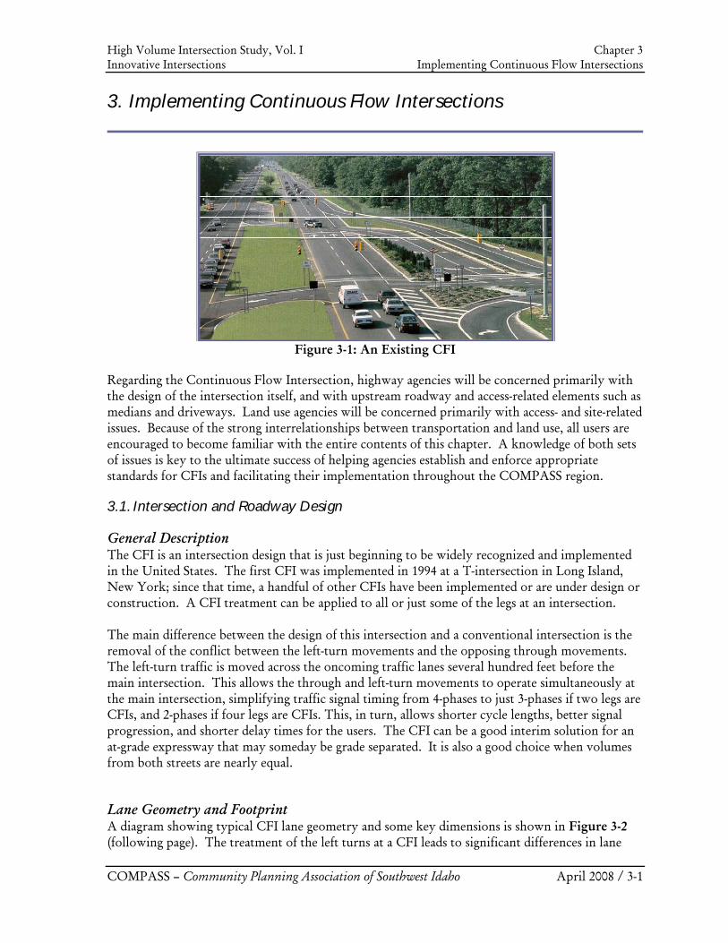
High Volume Intersection Study, Vol. I Chapter 3 Innovative Intersections Implementing Continuous Flow Intersections
COMPASS – Community Planning Association of Southwest Idaho April 2008 / 3-1
3. Implementing Continuous Flow Intersections
Figure 3-1: An Existing CFI
Regarding the Continuous Flow Intersection, highway agencies will be concerned primarily with the design of the intersection itself, and with upstream roadway and access-related elements such as medians and driveways. Land use agencies will be concerned primarily with access- and site-related issues. Because of the strong interrelationships between transportation and land use, all users are encouraged to become familiar with the entire contents of this chapter. A knowledge of both sets of issues is key to the ultimate success of helping agencies establish and enforce appropriate standards for CFIs and facilitating their implementation throughout the COMPASS region.
3.1. Intersection and Roadway Design
General Description The CFI is an intersection design that is just beginning to be widely recognized and implemented in the United States. The first CFI was implemented in 1994 at a T-intersection in Long Island, New York; since that time, a handful of other CFIs have been implemented or are under design or construction. A CFI treatment can be applied to all or just some of the legs at an intersection. The main difference between the design of this intersection and a conventional intersection is the removal of the conflict between the left-turn movements and the opposing through movements. The left-turn traffic is moved across the oncoming traffic lanes several hundred feet before the main intersection. This allows the through and left-turn movements to operate simultaneously at the main intersection, simplifying traffic signal timing from 4-phases to just 3-phases if two legs are CFIs, and 2-phases if four legs are CFIs. This, in turn, allows shorter cycle lengths, better signal progression, and shorter delay times for the users. The CFI can be a good interim solution for an at-grade expressway that may someday be grade separated. It is also a good choice when volumes from both streets are nearly equal.
Lane Geometry and Footprint A diagram showing typical CFI lane geometry and some key dimensions is shown in Figure 3-2 (following page). The treatment of the left turns at a CFI leads to significant differences in lane
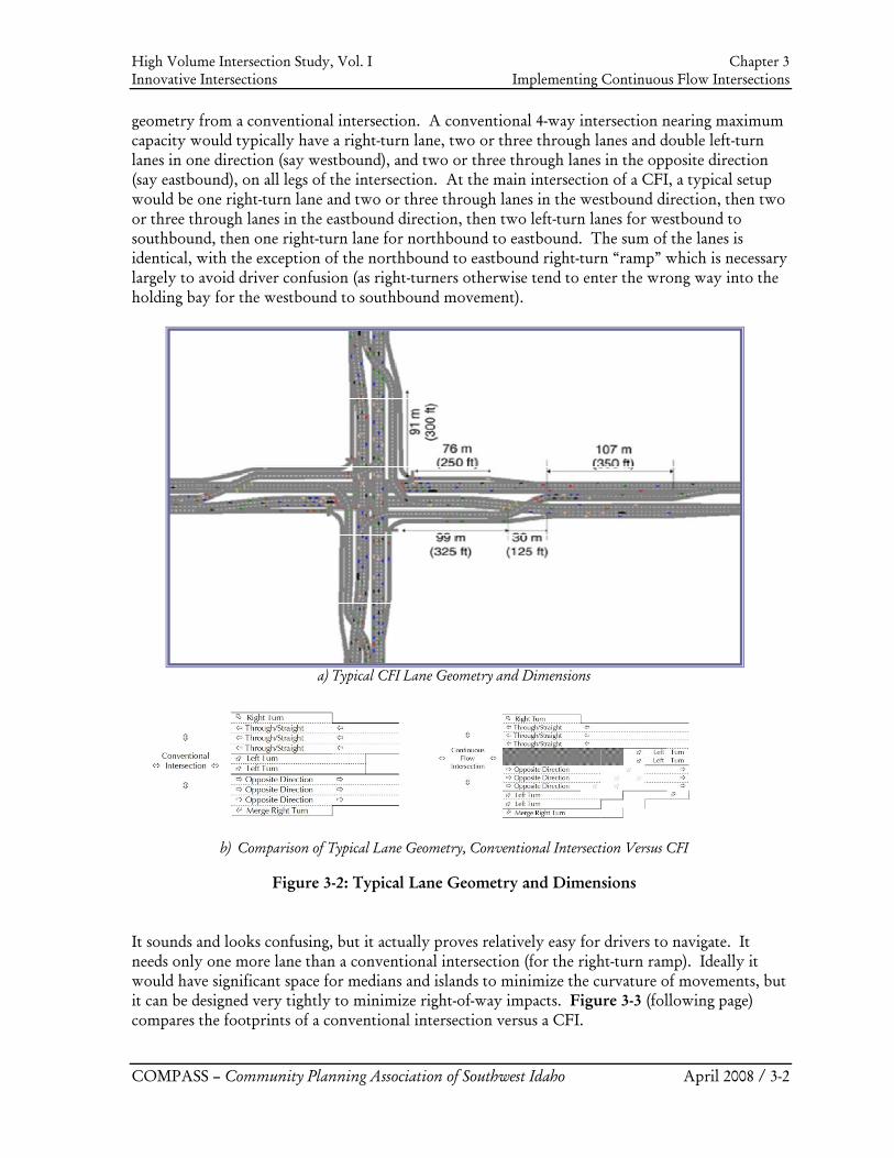
High Volume Intersection Study, Vol. I Chapter 3 Innovative Intersections Implementing Continuous Flow Intersections
COMPASS – Community Planning Association of Southwest Idaho April 2008 / 3-2
geometry from a conventional intersection. A conventional 4-way intersection nearing maximum capacity would typically have a right-turn lane, two or three through lanes and double left-turn lanes in one direction (say westbound), and two or three through lanes in the opposite direction (say eastbound), on all legs of the intersection. At the main intersection of a CFI, a typical setup would be one right-turn lane and two or three through lanes in the westbound direction, then two or three through lanes in the eastbound direction, then two left-turn lanes for westbound to southbound, then one right-turn lane for northbound to eastbound. The sum of the lanes is identical, with the exception of the northbound to eastbound right-turn “ramp” which is necessary largely to avoid driver confusion (as right-turners otherwise tend to enter the wrong way into the holding bay for the westbound to southbound movement).
a) Typical CFI Lane Geometry and Dimensions
b) Comparison of Typical Lane Geometry, Conventional Intersection Versus CFI
Figure 3-2: Typical Lane Geometry and Dimensions It sounds and looks confusing, but it actually proves relatively easy for drivers to navigate. It needs only one more lane than a conventional intersection (for the right-turn ramp). Ideally it would have significant space for medians and islands to minimize the curvature of movements, but it can be designed very tightly to minimize right-of-way impacts. Figure 3-3 (following page) compares the footprints of a conventional intersection versus a CFI.
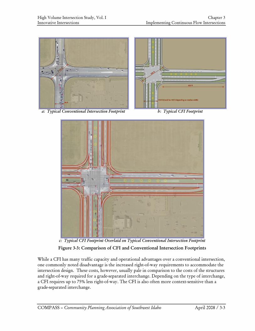
High Volume Intersection Study, Vol. I Chapter 3 Innovative Intersections Implementing Continuous Flow Intersections
COMPASS – Community Planning Association of Southwest Idaho April 2008 / 3-3
a: Typical Conventional Intersection Footprint
b: Typical CFI Footprint
c: Typical CFI Footprint Overlaid on Typical Conventional Intersection Footprint
Figure 3-3: Comparison of CFI and Conventional Intersection Footprints While a CFI has many traffic capacity and operational advantages over a conventional intersection, one commonly noted disadvantage is the increased right-of-way requirements to accommodate the intersection design. These costs, however, usually pale in comparison to the costs of the structures and right-of-way required for a grade-separated interchange. Depending on the type of interchange, a CFI requires up to 75% less right-of-way. The CFI is also often more context-sensitive than a grade-separated interchange.
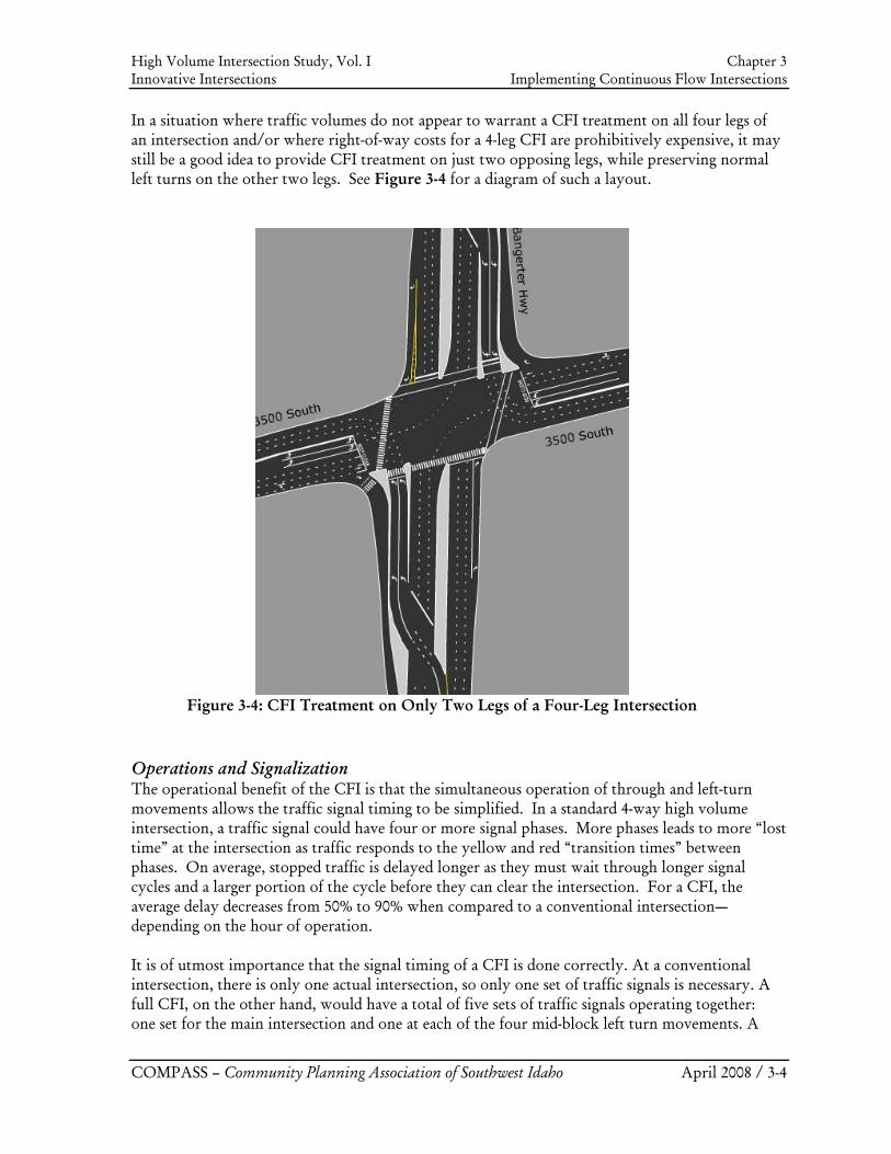
High Volume Intersection Study, Vol. I Chapter 3 Innovative Intersections Implementing Continuous Flow Intersections
COMPASS – Community Planning Association of Southwest Idaho April 2008 / 3-4
In a situation where traffic volumes do not appear to warrant a CFI treatment on all four legs of an intersection and/or where right-of-way costs for a 4-leg CFI are prohibitively expensive, it may still be a good idea to provide CFI treatment on just two opposing legs, while preserving normal left turns on the other two legs. See Figure 3-4 for a diagram of such a layout.
Figure 3-4: CFI Treatment on Only Two Legs of a Four-Leg Intersection
Operations and Signalization The operational benefit of the CFI is that the simultaneous operation of through and left-turn movements allows the traffic signal timing to be simplified. In a standard 4-way high volume intersection, a traffic signal could have four or more signal phases. More phases leads to more “lost time” at the intersection as traffic responds to the yellow and red “transition times” between phases. On average, stopped traffic is delayed longer as they must wait through longer signal cycles and a larger portion of the cycle before they can clear the intersection. For a CFI, the average delay decreases from 50% to 90% when compared to a conventional intersection—depending on the hour of operation. It is of utmost importance that the signal timing of a CFI is done correctly. At a conventional intersection, there is only one actual intersection, so only one set of traffic signals is necessary. A full CFI, on the other hand, would have a total of five sets of traffic signals operating together: one set for the main intersection and one at each of the four mid-block left turn movements. A
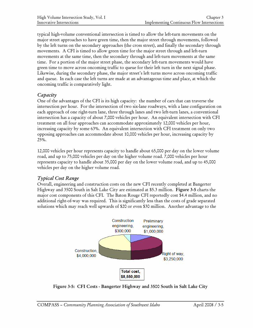
High Volume Intersection Study, Vol. I Chapter 3 Innovative Intersections Implementing Continuous Flow Intersections
COMPASS – Community Planning Association of Southwest Idaho April 2008 / 3-5
typical high-volume conventional intersection is timed to allow the left-turn movements on the major street approaches to have green time, then the major street through movements, followed by the left turns on the secondary approaches (the cross street), and finally the secondary through movements. A CFI is timed to allow green time for the major street through and left-turn movements at the same time, then the secondary through and left-turn movements at the same time. For a portion of the major street phase, the secondary left-turn movements would have green time to move across oncoming traffic to queue for their left turn in the next signal phase. Likewise, during the secondary phase, the major street’s left turns move across oncoming traffic and queue. In each case the left turns are made at an advantageous time and place, at which the oncoming traffic is comparatively light.
Capacity One of the advantages of the CFI is its high capacity: the number of cars that can traverse the intersection per hour. For the intersection of two six-lane roadways, with a lane configuration on each approach of one right-turn lane, three through lanes and two left-turn lanes, a conventional intersection has a capacity of about 7,000 vehicles per hour. An equivalent intersection with CFI treatment on all four approaches can accommodate approximately 12,000 vehicles per hour, increasing capacity by some 63%. An equivalent intersection with CFI treatment on only two opposing approaches can accommodate about 10,000 vehicles per hour, increasing capacity by 25%. 12,000 vehicles per hour represents capacity to handle about 65,000 per day on the lower volume road, and up to 75,000 vehicles per day on the higher volume road. 7,000 vehicles per hour represents capacity to handle about 35,000 per day on the lower volume road, and up to 45,000 vehicles per day on the higher volume road.
Typical Cost Range Overall, engineering and construction costs on the new CFI recently completed at Bangerter Highway and 3500 South in Salt Lake City are estimated at $5.3 million. Figure 3-5 charts the major cost components of this CFI. The Baton Rouge CFI reportedly cost $4.4 million, and no additional right-of-way was required. This is significantly less than the costs of grade separated solutions which may reach well upwards of $20 or even $30 million. Another advantage to the
Figure 3-5: CFI Costs - Bangerter Highway and 3500 South in Salt Lake City
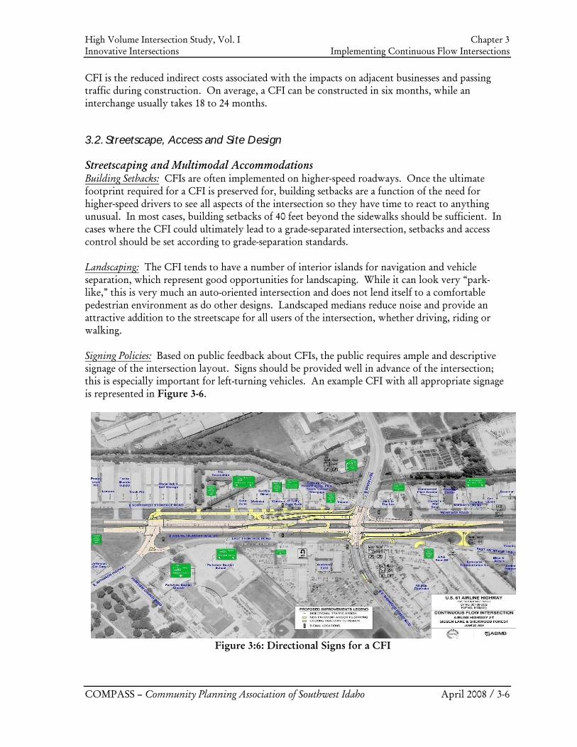
High Volume Intersection Study, Vol. I Chapter 3 Innovative Intersections Implementing Continuous Flow Intersections
COMPASS – Community Planning Association of Southwest Idaho April 2008 / 3-6
CFI is the reduced indirect costs associated with the impacts on adjacent businesses and passing traffic during construction. On average, a CFI can be constructed in six months, while an interchange usually takes 18 to 24 months.
3.2. Streetscape, Access and Site Design
Streetscaping and Multimodal Accommodations Building Setbacks: CFIs are often implemented on higher-speed roadways. Once the ultimate footprint required for a CFI is preserved for, building setbacks are a function of the need for higher-speed drivers to see all aspects of the intersection so they have time to react to anything unusual. In most cases, building setbacks of 40 feet beyond the sidewalks should be sufficient. In cases where the CFI could ultimately lead to a grade-separated intersection, setbacks and access control should be set according to grade-separation standards. Landscaping: The CFI tends to have a number of interior islands for navigation and vehicle separation, which represent good opportunities for landscaping. While it can look very “park-like,” this is very much an auto-oriented intersection and does not lend itself to a comfortable pedestrian environment as do other designs. Landscaped medians reduce noise and provide an attractive addition to the streetscape for all users of the intersection, whether driving, riding or walking. Signing Policies: Based on public feedback about CFIs, the public requires ample and descriptive signage of the intersection layout. Signs should be provided well in advance of the intersection; this is especially important for left-turning vehicles. An example CFI with all appropriate signage is represented in Figure 3-6.
Figure 3:6: Directional Signs for a CFI
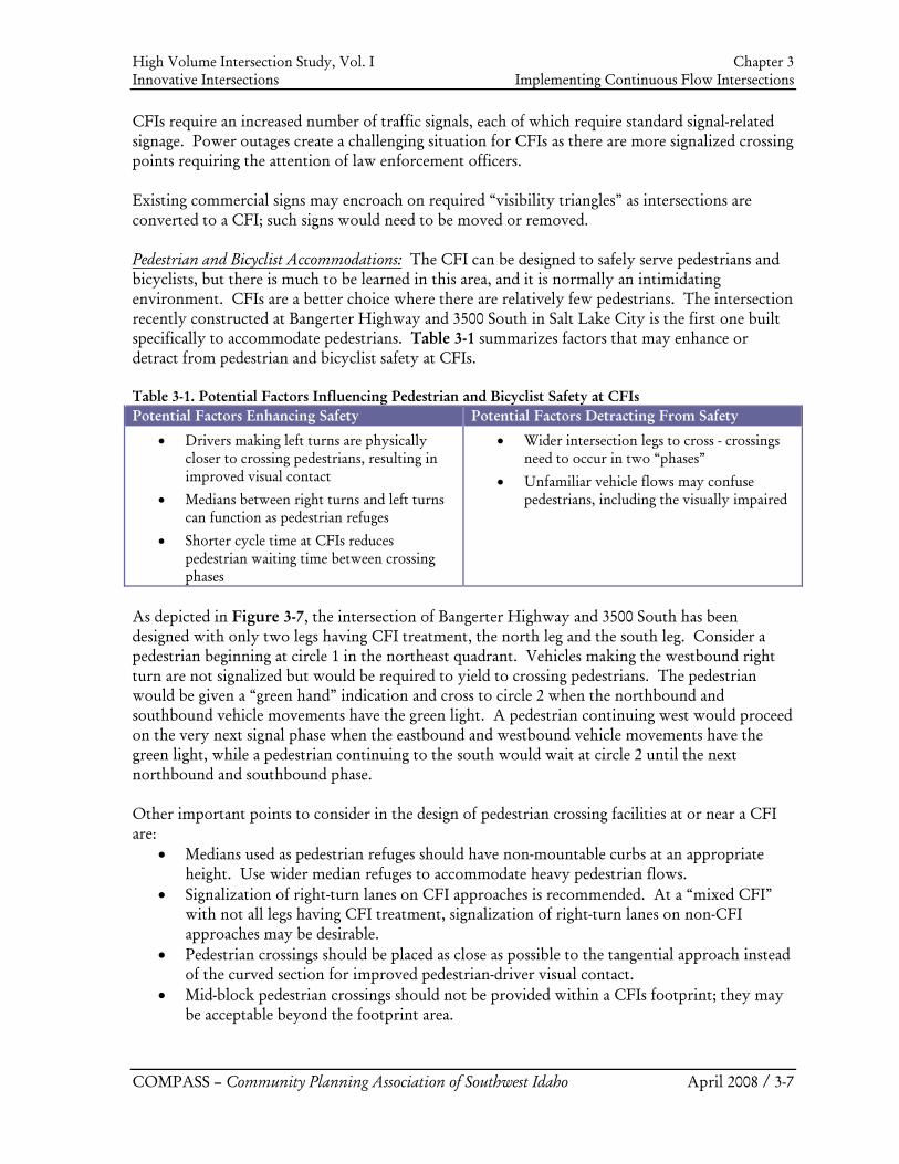
High Volume Intersection Study, Vol. I Chapter 3 Innovative Intersections Implementing Continuous Flow Intersections
COMPASS – Community Planning Association of Southwest Idaho April 2008 / 3-7
CFIs require an increased number of traffic signals, each of which require standard signal-related signage. Power outages create a challenging situation for CFIs as there are more signalized crossing points requiring the attention of law enforcement officers. Existing commercial signs may encroach on required “visibility triangles” as intersections are converted to a CFI; such signs would need to be moved or removed. Pedestrian and Bicyclist Accommodations: The CFI can be designed to safely serve pedestrians and bicyclists, but there is much to be learned in this area, and it is normally an intimidating environment. CFIs are a better choice where there are relatively few pedestrians. The intersection recently constructed at Bangerter Highway and 3500 South in Salt Lake City is the first one built specifically to accommodate pedestrians. Table 3-1 summarizes factors that may enhance or detract from pedestrian and bicyclist safety at CFIs. Table 3-1. Potential Factors Influencing Pedestrian and Bicyclist Safety at CFIs Potential Factors Enhancing Safety Potential Factors Detracting From Safety
• Drivers making left turns are physically closer to crossing pedestrians, resulting in improved visual contact
• Medians between right turns and left turns can function as pedestrian refuges
• Shorter cycle time at CFIs reduces pedestrian waiting time between crossing phases
• Wider intersection legs to cross - crossings need to occur in two “phases”
• Unfamiliar vehicle flows may confuse pedestrians, including the visually impaired
As depicted in Figure 3-7, the intersection of Bangerter Highway and 3500 South has been designed with only two legs having CFI treatment, the north leg and the south leg. Consider a pedestrian beginning at circle 1 in the northeast quadrant. Vehicles making the westbound right turn are not signalized but would be required to yield to crossing pedestrians. The pedestrian would be given a “green hand” indication and cross to circle 2 when the northbound and southbound vehicle movements have the green light. A pedestrian continuing west would proceed on the very next signal phase when the eastbound and westbound vehicle movements have the green light, while a pedestrian continuing to the south would wait at circle 2 until the next northbound and southbound phase. Other important points to consider in the design of pedestrian crossing facilities at or near a CFI are:
• Medians used as pedestrian refuges should have non-mountable curbs at an appropriate height. Use wider median refuges to accommodate heavy pedestrian flows.
• Signalization of right-turn lanes on CFI approaches is recommended. At a “mixed CFI” with not all legs having CFI treatment, signalization of right-turn lanes on non-CFI approaches may be desirable.
• Pedestrian crossings should be placed as close as possible to the tangential approach instead of the curved section for improved pedestrian-driver visual contact.
• Mid-block pedestrian crossings should not be provided within a CFIs footprint; they may be acceptable beyond the footprint area.
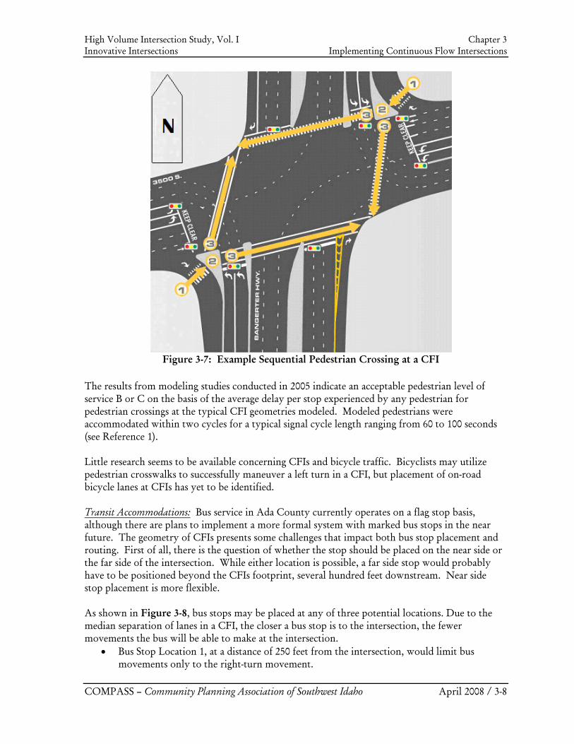
High Volume Intersection Study, Vol. I Chapter 3 Innovative Intersections Implementing Continuous Flow Intersections
COMPASS – Community Planning Association of Southwest Idaho April 2008 / 3-8
Figure 3-7: Example Sequential Pedestrian Crossing at a CFI
The results from modeling studies conducted in 2005 indicate an acceptable pedestrian level of service B or C on the basis of the average delay per stop experienced by any pedestrian for pedestrian crossings at the typical CFI geometries modeled. Modeled pedestrians were accommodated within two cycles for a typical signal cycle length ranging from 60 to 100 seconds (see Reference 1). Little research seems to be available concerning CFIs and bicycle traffic. Bicyclists may utilize pedestrian crosswalks to successfully maneuver a left turn in a CFI, but placement of on-road bicycle lanes at CFIs has yet to be identified. Transit Accommodations: Bus service in Ada County currently operates on a flag stop basis, although there are plans to implement a more formal system with marked bus stops in the near future. The geometry of CFIs presents some challenges that impact both bus stop placement and routing. First of all, there is the question of whether the stop should be placed on the near side or the far side of the intersection. While either location is possible, a far side stop would probably have to be positioned beyond the CFIs footprint, several hundred feet downstream. Near side stop placement is more flexible. As shown in Figure 3-8, bus stops may be placed at any of three potential locations. Due to the median separation of lanes in a CFI, the closer a bus stop is to the intersection, the fewer movements the bus will be able to make at the intersection.
• Bus Stop Location 1, at a distance of 250 feet from the intersection, would limit bus movements only to the right-turn movement.
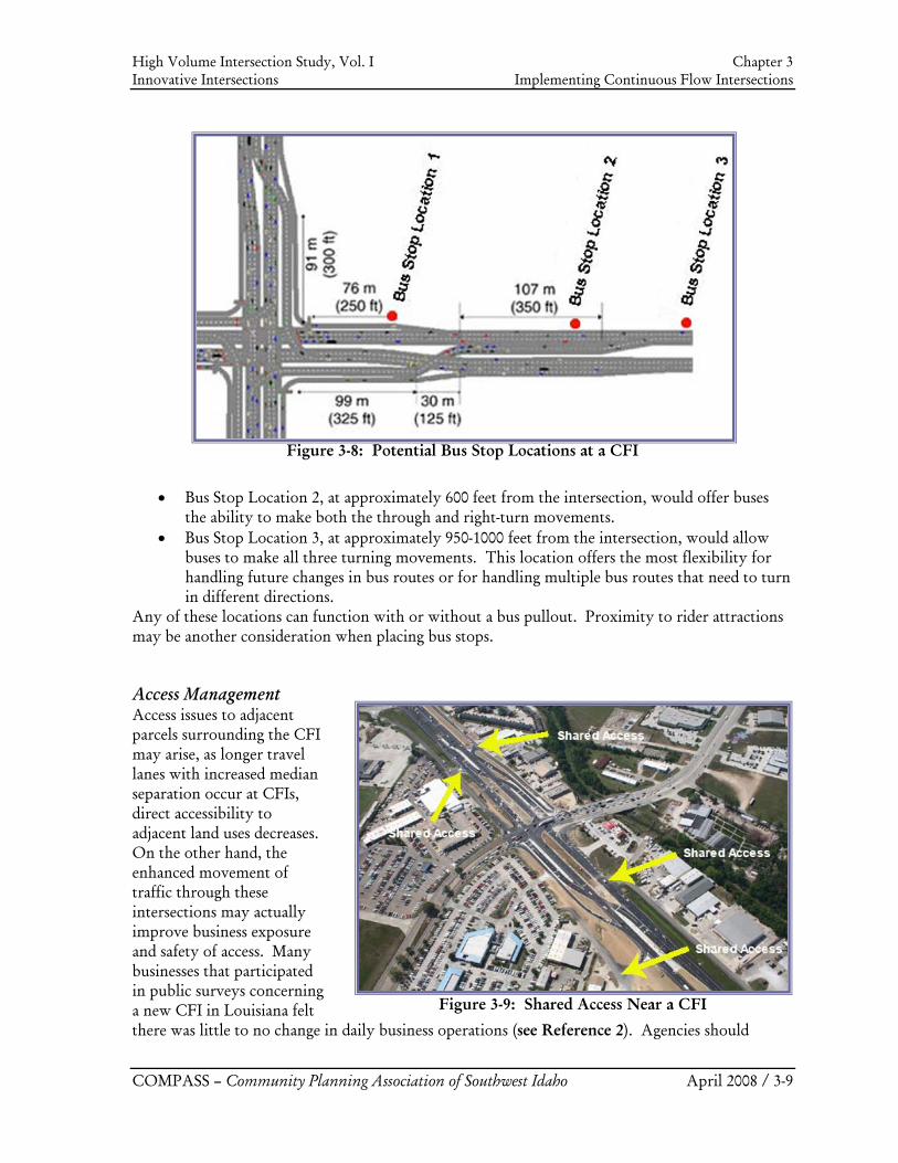
High Volume Intersection Study, Vol. I Chapter 3 Innovative Intersections Implementing Continuous Flow Intersections
COMPASS – Community Planning Association of Southwest Idaho April 2008 / 3-9
• Bus Stop Location 2, at approximately 600 feet from the intersection, would offer buses the ability to make both the through and right-turn movements.
• Bus Stop Location 3, at approximately 950-1000 feet from the intersection, would allow buses to make all three turning movements. This location offers the most flexibility for handling future changes in bus routes or for handling multiple bus routes that need to turn in different directions.
Any of these locations can function with or without a bus pullout. Proximity to rider attractions may be another consideration when placing bus stops.
Access Management Access issues to adjacent parcels surrounding the CFI may arise, as longer travel lanes with increased median separation occur at CFIs, direct accessibility to adjacent land uses decreases. On the other hand, the enhanced movement of traffic through these intersections may actually improve business exposure and safety of access. Many businesses that participated in public surveys concerning a new CFI in Louisiana felt there was little to no change in daily business operations (see Reference 2). Agencies should
Figure 3-8: Potential Bus Stop Locations at a CFI
Figure 3-9: Shared Access Near a CFI
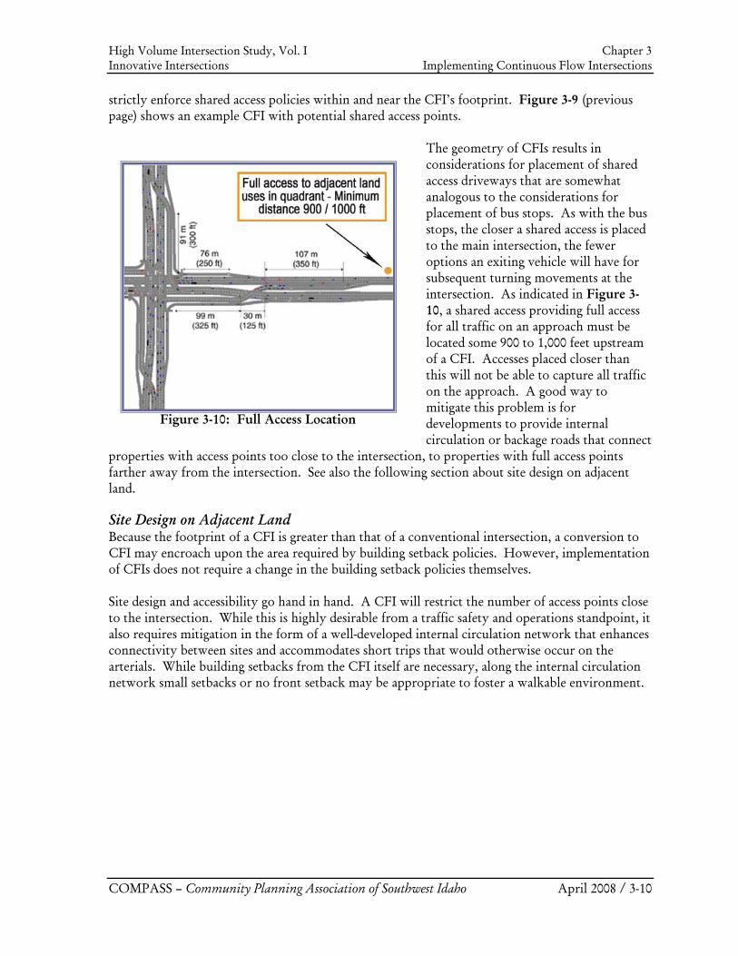
High Volume Intersection Study, Vol. I Chapter 3 Innovative Intersections Implementing Continuous Flow Intersections
COMPASS – Community Planning Association of Southwest Idaho April 2008 / 3-10
strictly enforce shared access policies within and near the CFI’s footprint. Figure 3-9 (previous page) shows an example CFI with potential shared access points.
The geometry of CFIs results in considerations for placement of shared access driveways that are somewhat analogous to the considerations for placement of bus stops. As with the bus stops, the closer a shared access is placed to the main intersection, the fewer options an exiting vehicle will have for subsequent turning movements at the intersection. As indicated in Figure 3-10, a shared access providing full access for all traffic on an approach must be located some 900 to 1,000 feet upstream of a CFI. Accesses placed closer than this will not be able to capture all traffic on the approach. A good way to mitigate this problem is for developments to provide internal circulation or backage roads that connect
properties with access points too close to the intersection, to properties with full access points farther away from the intersection. See also the following section about site design on adjacent land.
Site Design on Adjacent Land Because the footprint of a CFI is greater than that of a conventional intersection, a conversion to CFI may encroach upon the area required by building setback policies. However, implementation of CFIs does not require a change in the building setback policies themselves. Site design and accessibility go hand in hand. A CFI will restrict the number of access points close to the intersection. While this is highly desirable from a traffic safety and operations standpoint, it also requires mitigation in the form of a well-developed internal circulation network that enhances connectivity between sites and accommodates short trips that would otherwise occur on the arterials. While building setbacks from the CFI itself are necessary, along the internal circulation network small setbacks or no front setback may be appropriate to foster a walkable environment.
Figure 3-10: Full Access Location
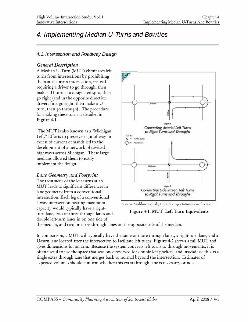
High Volume Intersection Study, Vol. I Chapter 4 Innovative Intersections Implementing Median U-Turns And Bowties
COMPASS – Community Planning Association of Southwest Idaho April 2008 / 4-1
4. Implementing Median U-Turns and Bowties
4.1. Intersection and Roadway Design
General Description A Median U-Turn (MUT) eliminates left turns from intersections by prohibiting them at the main intersection, instead requiring a driver to go through, then make a U-turn at a designated spot, then go right (and in the opposite direction drivers first go right, then make a U-turn, then go through). The procedure for making these turns is detailed in Figure 4-1.
The MUT is also known as a “Michigan Left.” Efforts to preserve right-of-way in excess of current demands led to the development of a network of divided highways across Michigan. These large medians allowed them to easily implement the design.
Lane Geometry and Footprint The treatment of the left turns at an MUT leads to significant differences in lane geometry from a conventional intersection. Each leg of a conventional 4-way intersection nearing maximum capacity would typically have a right-turn lane, two or three through lanes and double left-turn lanes in on one side of the median, and two or three through lanes on the opposite side of the median. In comparison, a MUT will typically have the same or more through lanes, a right-turn lane, and a U-turn lane located after the intersection to facilitate left turns. Figure 4-2 shows a full MUT and gives dimensions for an arm. Because the system converts left turns to through movements, it is often useful to use the space that was once reserved for double-left pockets, and instead use this as a single extra through lane that merges back to normal beyond the intersection. Estimates of expected volumes should confirm whether this extra through lane is necessary or not.
Figure 4-1: MUT Left Turn Equivalents
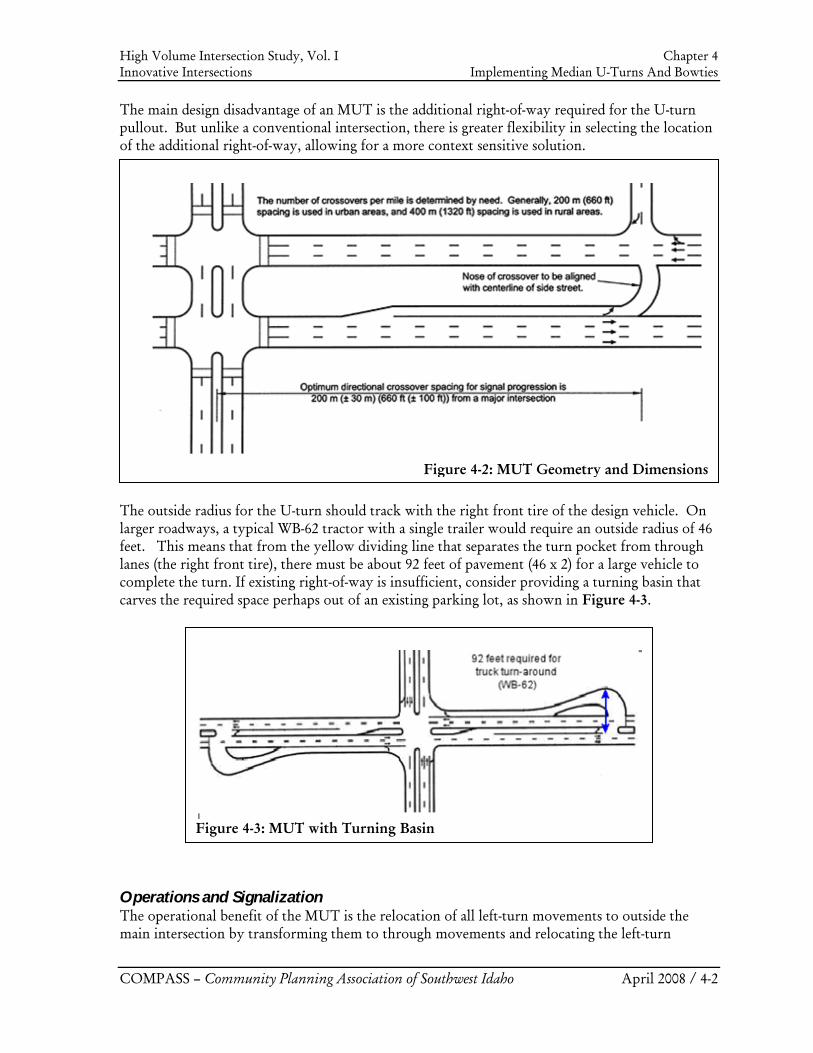
High Volume Intersection Study, Vol. I Chapter 4 Innovative Intersections Implementing Median U-Turns And Bowties
COMPASS – Community Planning Association of Southwest Idaho April 2008 / 4-2
Figure 4-2: MUT Geometry and Dimensions
Figure 4-3: MUT with Turning Basin
The main design disadvantage of an MUT is the additional right-of-way required for the U-turn pullout. But unlike a conventional intersection, there is greater flexibility in selecting the location of the additional right-of-way, allowing for a more context sensitive solution.
The outside radius for the U-turn should track with the right front tire of the design vehicle. On larger roadways, a typical WB-62 tractor with a single trailer would require an outside radius of 46 feet. This means that from the yellow dividing line that separates the turn pocket from through lanes (the right front tire), there must be about 92 feet of pavement (46 x 2) for a large vehicle to complete the turn. If existing right-of-way is insufficient, consider providing a turning basin that carves the required space perhaps out of an existing parking lot, as shown in Figure 4-3.
Operations and Signalization The operational benefit of the MUT is the relocation of all left-turn movements to outside the main intersection by transforming them to through movements and relocating the left-turn
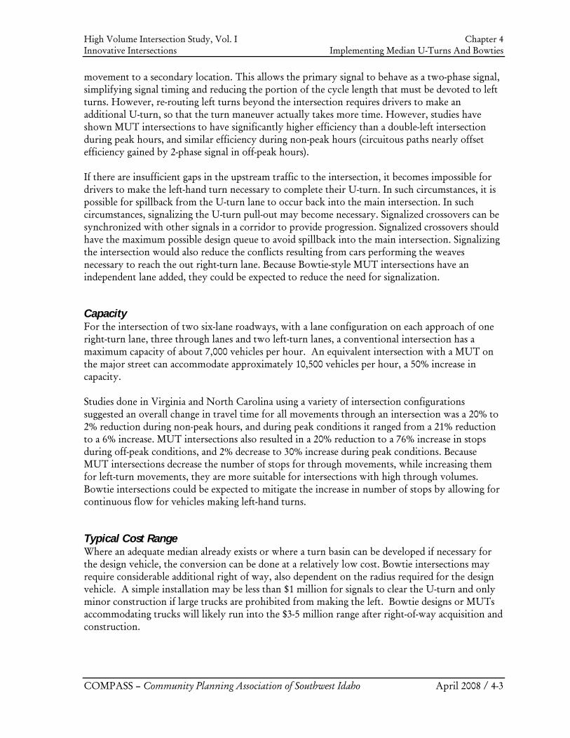
High Volume Intersection Study, Vol. I Chapter 4 Innovative Intersections Implementing Median U-Turns And Bowties
COMPASS – Community Planning Association of Southwest Idaho April 2008 / 4-3
movement to a secondary location. This allows the primary signal to behave as a two-phase signal, simplifying signal timing and reducing the portion of the cycle length that must be devoted to left turns. However, re-routing left turns beyond the intersection requires drivers to make an additional U-turn, so that the turn maneuver actually takes more time. However, studies have shown MUT intersections to have significantly higher efficiency than a double-left intersection during peak hours, and similar efficiency during non-peak hours (circuitous paths nearly offset efficiency gained by 2-phase signal in off-peak hours). If there are insufficient gaps in the upstream traffic to the intersection, it becomes impossible for drivers to make the left-hand turn necessary to complete their U-turn. In such circumstances, it is possible for spillback from the U-turn lane to occur back into the main intersection. In such circumstances, signalizing the U-turn pull-out may become necessary. Signalized crossovers can be synchronized with other signals in a corridor to provide progression. Signalized crossovers should have the maximum possible design queue to avoid spillback into the main intersection. Signalizing the intersection would also reduce the conflicts resulting from cars performing the weaves necessary to reach the out right-turn lane. Because Bowtie-style MUT intersections have an independent lane added, they could be expected to reduce the need for signalization.
Capacity For the intersection of two six-lane roadways, with a lane configuration on each approach of one right-turn lane, three through lanes and two left-turn lanes, a conventional intersection has a maximum capacity of about 7,000 vehicles per hour. An equivalent intersection with a MUT on the major street can accommodate approximately 10,500 vehicles per hour, a 50% increase in capacity. Studies done in Virginia and North Carolina using a variety of intersection configurations suggested an overall change in travel time for all movements through an intersection was a 20% to 2% reduction during non-peak hours, and during peak conditions it ranged from a 21% reduction to a 6% increase. MUT intersections also resulted in a 20% reduction to a 76% increase in stops during off-peak conditions, and 2% decrease to 30% increase during peak conditions. Because MUT intersections decrease the number of stops for through movements, while increasing them for left-turn movements, they are more suitable for intersections with high through volumes. Bowtie intersections could be expected to mitigate the increase in number of stops by allowing for continuous flow for vehicles making left-hand turns.
Typical Cost Range Where an adequate median already exists or where a turn basin can be developed if necessary for the design vehicle, the conversion can be done at a relatively low cost. Bowtie intersections may require considerable additional right of way, also dependent on the radius required for the design vehicle. A simple installation may be less than $1 million for signals to clear the U-turn and only minor construction if large trucks are prohibited from making the left. Bowtie designs or MUTs accommodating trucks will likely run into the $3-5 million range after right-of-way acquisition and construction.
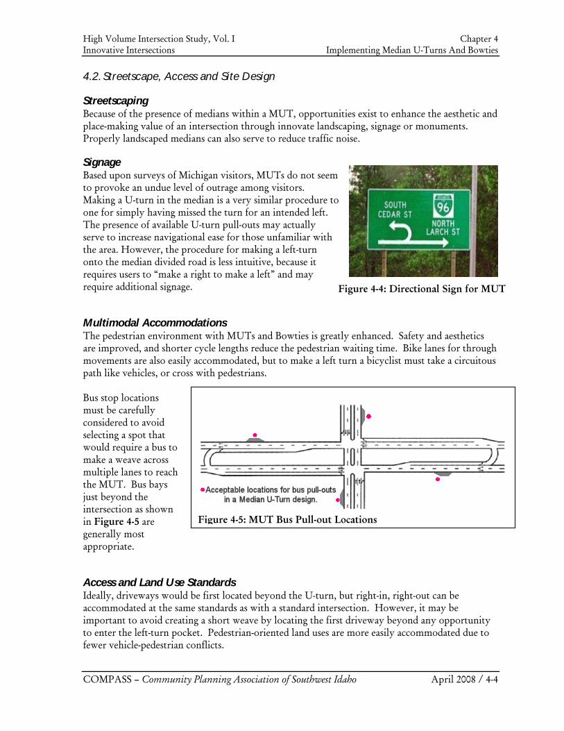
High Volume Intersection Study, Vol. I Chapter 4 Innovative Intersections Implementing Median U-Turns And Bowties
COMPASS – Community Planning Association of Southwest Idaho April 2008 / 4-4
Figure 4-5: MUT Bus Pull-out Locations
4.2. Streetscape, Access and Site Design
Streetscaping Because of the presence of medians within a MUT, opportunities exist to enhance the aesthetic and place-making value of an intersection through innovate landscaping, signage or monuments. Properly landscaped medians can also serve to reduce traffic noise.
Signage Based upon surveys of Michigan visitors, MUTs do not seem to provoke an undue level of outrage among visitors. Making a U-turn in the median is a very similar procedure to one for simply having missed the turn for an intended left. The presence of available U-turn pull-outs may actually serve to increase navigational ease for those unfamiliar with the area. However, the procedure for making a left-turn onto the median divided road is less intuitive, because it requires users to “make a right to make a left” and may require additional signage.
Multimodal Accommodations The pedestrian environment with MUTs and Bowties is greatly enhanced. Safety and aesthetics are improved, and shorter cycle lengths reduce the pedestrian waiting time. Bike lanes for through movements are also easily accommodated, but to make a left turn a bicyclist must take a circuitous path like vehicles, or cross with pedestrians. Bus stop locations must be carefully considered to avoid selecting a spot that would require a bus to make a weave across multiple lanes to reach the MUT. Bus bays just beyond the intersection as shown in Figure 4-5 are generally most appropriate.
Access and Land Use Standards Ideally, driveways would be first located beyond the U-turn, but right-in, right-out can be accommodated at the same standards as with a standard intersection. However, it may be important to avoid creating a short weave by locating the first driveway beyond any opportunity to enter the left-turn pocket. Pedestrian-oriented land uses are more easily accommodated due to fewer vehicle-pedestrian conflicts.
Figure 4-4: Directional Sign for MUT
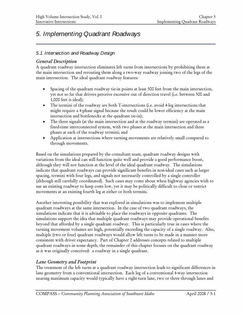
High Volume Intersection Study, Vol. I Chapter 5 Innovative Intersections Implementing Quadrant Roadways
COMPASS – Community Planning Association of Southwest Idaho April 2008 / 5-1
5. Implementing Quadrant Roadways
5.1. Intersection and Roadway Design
General Description A quadrant roadway intersection eliminates left turns from intersections by prohibiting them at the main intersection and rerouting them along a two-way roadway joining two of the legs of the main intersection. The ideal quadrant roadway features:
• Spacing of the quadrant roadway tie-in points at least 500 feet from the main intersection, yet not so far that drivers perceive excessive out of direction travel (i.e. between 500 and 1,000 feet is ideal);
• The termini of the roadway are both T-intersections (i.e. avoid 4-leg intersections that might require a 4-phase signal because the result could be lower efficiency at the main intersection and bottlenecks at the quadrant tie-in);
• The three signals (at the main intersection and at the roadway termini) are operated as a fixed-time interconnected system, with two phases at the main intersection and three phases at each of the roadway termini; and
• Application at intersections where turning movements are relatively small compared to through movements.
Based on the simulations prepared by the consultant team, quadrant roadway designs with variations from the ideal can still function quite well and provide a good performance boost, although they will not function at the level of the ideal quadrant roadway. The simulations indicate that quadrant roadways can provide significant benefits in non-ideal cases such as larger spacing, termini with four legs, and signals not necessarily controlled by a single controller (although still carefully coordinated). Such cases may come about when highway agencies wish to use an existing roadway to keep costs low, yet it may be politically difficult to close or restrict movements at an existing fourth leg at either or both termini.
Another interesting possibility that was explored in simulations was to implement multiple quadrant roadways at the same intersection. In the case of two quadrant roadways, the simulations indicate that it is advisable to place the roadways in opposite quadrants. The simulations support the idea that multiple quadrant roadways may provide operational benefits beyond that afforded by a single quadrant roadway. This is particularly true in cases where the turning movement volumes are high, potentially exceeding the capacity of a single roadway. Also, multiple (two or four) quadrant roadways would allow left turns to be made in a manner more consistent with driver expectancy. Part of Chapter 2 addresses concepts related to multiple quadrant roadways in some depth; the remainder of this chapter focuses on the quadrant roadway as it was originally conceived: a roadway in a single quadrant.
Lane Geometry and Footprint The treatment of the left turns at a quadrant roadway intersection leads to significant differences in lane geometry from a conventional intersection. Each leg of a conventional 4-way intersection nearing maximum capacity would typically have a right-turn lane, two or three through lanes and
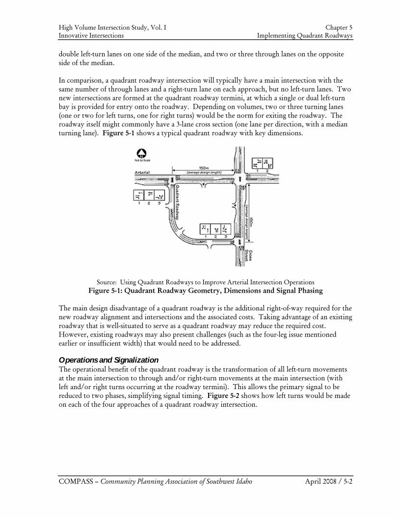
High Volume Intersection Study, Vol. I Chapter 5 Innovative Intersections Implementing Quadrant Roadways
COMPASS – Community Planning Association of Southwest Idaho April 2008 / 5-2
double left-turn lanes on one side of the median, and two or three through lanes on the opposite side of the median. In comparison, a quadrant roadway intersection will typically have a main intersection with the same number of through lanes and a right-turn lane on each approach, but no left-turn lanes. Two new intersections are formed at the quadrant roadway termini, at which a single or dual left-turn bay is provided for entry onto the roadway. Depending on volumes, two or three turning lanes (one or two for left turns, one for right turns) would be the norm for exiting the roadway. The roadway itself might commonly have a 3-lane cross section (one lane per direction, with a median turning lane). Figure 5-1 shows a typical quadrant roadway with key dimensions.
Source: Using Quadrant Roadways to Improve Arterial Intersection Operations Figure 5-1: Quadrant Roadway Geometry, Dimensions and Signal Phasing
The main design disadvantage of a quadrant roadway is the additional right-of-way required for the new roadway alignment and intersections and the associated costs. Taking advantage of an existing roadway that is well-situated to serve as a quadrant roadway may reduce the required cost. However, existing roadways may also present challenges (such as the four-leg issue mentioned earlier or insufficient width) that would need to be addressed.
Operations and Signalization The operational benefit of the quadrant roadway is the transformation of all left-turn movements at the main intersection to through and/or right-turn movements at the main intersection (with left and/or right turns occurring at the roadway termini). This allows the primary signal to be reduced to two phases, simplifying signal timing. Figure 5-2 shows how left turns would be made on each of the four approaches of a quadrant roadway intersection.
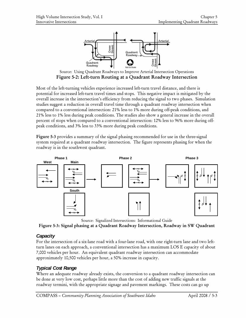
High Volume Intersection Study, Vol. I Chapter 5 Innovative Intersections Implementing Quadrant Roadways
COMPASS – Community Planning Association of Southwest Idaho April 2008 / 5-3
Source: Using Quadrant Roadways to Improve Arterial Intersection Operations
Figure 5-2: Left-turn Routing at a Quadrant Roadway Intersection Most of the left-turning vehicles experience increased left-turn travel distance, and there is potential for increased left-turn travel times and stops. This negative impact is mitigated by the overall increase in the intersection’s efficiency from reducing the signal to two phases. Simulation studies suggest a reduction in overall travel time through a quadrant roadway intersection when compared to a conventional intersection: 21% less to 1% more during off-peak conditions, and 21% less to 1% less during peak conditions. The studies also show a general increase in the overall percent of stops when compared to a conventional intersection: 12% less to 96% more during off-peak conditions, and 3% less to 33% more during peak conditions. Figure 5-3 provides a summary of the signal phasing recommended for use in the three-signal system required at a quadrant roadway intersection. The figure represents phasing for when the roadway is in the southwest quadrant.
Source: Signalized Intersections: Informational Guide Figure 5-3: Signal phasing at a Quadrant Roadway Intersection, Roadway in SW Quadrant
Capacity For the intersection of a six-lane road with a four-lane road, with one right-turn lane and two left- turn lanes on each approach, a conventional intersection has a maximum LOS E capacity of about 7,000 vehicles per hour. An equivalent quadrant roadway intersection can accommodate approximately 10,500 vehicles per hour, a 50% increase in capacity.
Typical Cost Range Where an adequate roadway already exists, the conversion to a quadrant roadway intersection can be done at very low cost, perhaps little more than the cost of adding new traffic signals at the roadway termini, with the appropriate signage and pavement markings. These costs can go up
West Main
South
Phase 1 Phase 2 Phase 3
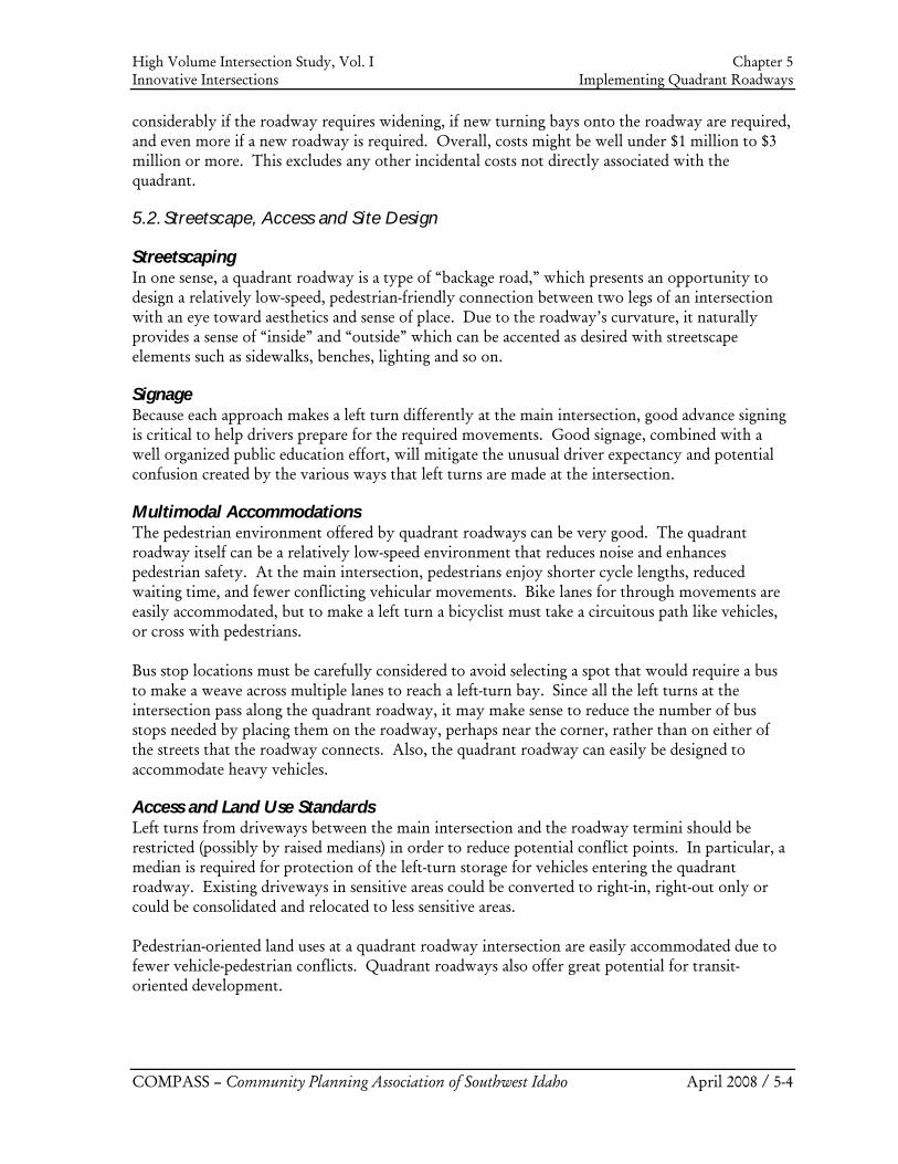
High Volume Intersection Study, Vol. I Chapter 5 Innovative Intersections Implementing Quadrant Roadways
COMPASS – Community Planning Association of Southwest Idaho April 2008 / 5-4
considerably if the roadway requires widening, if new turning bays onto the roadway are required, and even more if a new roadway is required. Overall, costs might be well under $1 million to $3 million or more. This excludes any other incidental costs not directly associated with the quadrant.
5.2. Streetscape, Access and Site Design
Streetscaping In one sense, a quadrant roadway is a type of “backage road,” which presents an opportunity to design a relatively low-speed, pedestrian-friendly connection between two legs of an intersection with an eye toward aesthetics and sense of place. Due to the roadway’s curvature, it naturally provides a sense of “inside” and “outside” which can be accented as desired with streetscape elements such as sidewalks, benches, lighting and so on.
Signage Because each approach makes a left turn differently at the main intersection, good advance signing is critical to help drivers prepare for the required movements. Good signage, combined with a well organized public education effort, will mitigate the unusual driver expectancy and potential confusion created by the various ways that left turns are made at the intersection.
Multimodal Accommodations The pedestrian environment offered by quadrant roadways can be very good. The quadrant roadway itself can be a relatively low-speed environment that reduces noise and enhances pedestrian safety. At the main intersection, pedestrians enjoy shorter cycle lengths, reduced waiting time, and fewer conflicting vehicular movements. Bike lanes for through movements are easily accommodated, but to make a left turn a bicyclist must take a circuitous path like vehicles, or cross with pedestrians. Bus stop locations must be carefully considered to avoid selecting a spot that would require a bus to make a weave across multiple lanes to reach a left-turn bay. Since all the left turns at the intersection pass along the quadrant roadway, it may make sense to reduce the number of bus stops needed by placing them on the roadway, perhaps near the corner, rather than on either of the streets that the roadway connects. Also, the quadrant roadway can easily be designed to accommodate heavy vehicles.
Access and Land Use Standards Left turns from driveways between the main intersection and the roadway termini should be restricted (possibly by raised medians) in order to reduce potential conflict points. In particular, a median is required for protection of the left-turn storage for vehicles entering the quadrant roadway. Existing driveways in sensitive areas could be converted to right-in, right-out only or could be consolidated and relocated to less sensitive areas. Pedestrian-oriented land uses at a quadrant roadway intersection are easily accommodated due to fewer vehicle-pedestrian conflicts. Quadrant roadways also offer great potential for transit-oriented development.
High Volume Intersection Study, Vol. I Innovative Intersections: Overview and Implementation Guidelines References
COMPASS – Community Planning Association of Southwest Idaho April 2008 / R-1
References
Several of these sources were used in completion of this report, and should also be researched prior to designing any innovative intersection.
1. Jagannathan, Ramanujan and Joe Bared, “Design and Performance Analysis of Pedestrian Crossing Facilities for Continuous Flow Intersections,” 2005. Transportation Research Record: Journal of the Transportation Research Board, No. 1939, pp 133-144.
2. Kalivoda III, Nick, "A Presentation on Louisiana's Continuous Flow Intersection (CFI)."
Presented at the AASHTO Subcommittee on Design Annual Meeting. June 11, 2007. http://www.transportation.org/sites/design/docs/Nick%20Kalivoda_Kalivoda%202007%20AASHTO%20SCOD%20Presentation.pdf.
3. Federal Highway Administration, “Signalized Intersections: Informational Guide.”
August 2004. FHWA-HRT-04-091 http://www.tfhrc.gov/safety/pubs/04091/index.htm
4. Wikipedia contributors, "Michigan left," Wikipedia, The Free Encyclopedia, http://en.wikipedia.org/w/index.php?title=Michigan_left&oldid=181969625 (accessed January 10, 2008).
5. Reid, Jonathan D. and Joseph E. Hummer, “Analyzing System Travel Time in Arterial
Corridors with Unconventional Designs Using Microscopic Simulation.” TRB Annual Meeting Preprint CD 1999. http://trafficware.com/assets/pdfs/00036.pdf
6. Waldman, Benjamin, Alex Ariniello, and S.M. Alam, “Eliminating Left-Turns at a
Signalized Intersection With The Use of Nearby Roundabouts.” May 30, 2007. Oregon ITE. http://www.oregonite.org/2007D6/paper_review/E6_106_Waldmanpaper.pdf
7. Reid, Jonathan D. and Joseph E. Hummer, “Unconventional Left-Turn Alternatives for
Urban and Suburban Arterials: An Update.” TRB Circular E-C019: Urban Street Symposium. http://onlinepubs.trb.org/onlinepubs/circulars/ec019/EC019_E3.PDF
8. Thompson, Cipriana D. and Joseph E. Hummer, “Guidance on the Safe Implementation
of Unconventional Arterial Designs.” September 17, 2001. Prepared for University of Tennessee at Knoxville.
9. Reid, Jonathan D., “Using Quadrant Roadways to Improve Arterial Intersection
Operations.” http://www.pbworld.com/news_events/publications/network/Issue_50/50_35_ReidJ_QuadrantRoadways.asp (accessed February 7, 2008).