Embed Size (px)
Citation preview

International Journal of Scientific Engineering and Research (IJSER) ISSN (Online): 2347-3878
Impact Factor (2018): 5.426
Volume 7 Issue 4, April 2019
www.ijser.in Licensed Under Creative Commons Attribution CC BY
High Volume Fly Ash-Based Glass Fibre
Reinforced Concrete
Somsubhra De1, Dr. Sudhir Kumar Das
2
1M Tech, Civil (Techno India College), Salt Lake, Sector-V
2Professor of Civil Eng. Department, Techno India College
1. Introduction
1.1 After completing my second semester I have started the
3rd
semester dealing with my thesis paper as stated above.I
have chosen this paper because I got grade “E” (80-
90%marks) in „Advanced Concrete Technology‟ (SE205B)
in my last University exam of MTech conducted by
MAKAUT. In my second semester Prof.Dr. Sudhir Kumar
Das (Dr. SKD) taught us SE205B. Due to his excellent
teaching I got “E” grade in the above subject. So, I have
chosen Prof.Dr. SKD as one of my guide with the
permission of HOD Prof.Dr. Arup SahaChaudhury (Dr.
ASC) of the above subject. I got consent of Dr. SKD to
guide me the above subject despite he used to keep busy
inother academic field.
1.2 Glass Fibre Reinforced Concrete:Glass fibre reinforced
concrete (GFRC) is a cementitious composite product
reinforced with discrete glass fibres of varying length and
size. The glass fibre used is alkaline resistant as glass fibre
are susceptible to alkali which decreases the durability of
GFRC. Glass strands are utilized for the most part for
outside claddings, veneer plates and differentcomponents
where their reinforcing impacts are required during
construction. GFRC is stiff in fresh state has lower slump
and hence less workable, therefore water reducing
admixtures are used. Further the properties of GFRC depend
on various parameters like method of producing the product.
It can be done by various methods like spraying, casting,
extrusion techniques etc. Cement type is also found to have
considerable effect on the GFRC. The length of the fibre,
sand/filler type, cement ratio methods and duration of curing
also effect the properties of GFRC.
1.3 Applications
The main area of FRC applications are: [5]
1) Runway, Aircraft parking, and Pavements
2) Tunnel Lining and Slope Stabilization
3) Blast Resistant Structures
4) Thin Shell, Walls, Pipes, and Manholes
5) Dams and Hydraulic Structure
6) GFRC is also used for machine tool frames, lighting
poles, water and oil tanks and also for concrete repairs.
1.4 Advantages and Disadvantages of using Glass Fibres
in Concrete:
1.4.1 Advantages
1) It is a great material for restoration of old building and is
used for the exterior of the buildings. It is also being used
extensively for walls and ceilings. Landscape artists have
come on board and discovered the versatility of GFRC.
2) GFRC is lightweight and is about 75% lighter than
traditional concrete. The lighter weight of GFRC brings
economy compare to conventional concrete while it is
used in RCC multi-storey frame structures with the
advantage of reducing the sections of slabs, beams and
columns including the sub-structures viz. foundations.
3) The flexural strength gives it a high strength to weight
ratio.
4) The reinforcement for this concrete is internal and does
not need additional reinforcements.
5) Heavy duty or expensive equipment is not necessary
when pouring or spraying GFRC.
6) It is easy to cut and is very difficult to crack.
7) GFRC is very adaptable in that it can be poured or
sprayed.
8) When sprayed, the surface finish has no pits or bug-
holes. If it is poured, it is easily shimmied to remove all
pits and bug-holes prior to hardening.
9) The wires used as one of the constituents of fibre
reinforce concrete help the concreting of superstructures
such as walls and ceiling and substructures such as
foundations to adhere concrete better than the
conventional concrete and have a stronger and durable
finish.
1.4.2 Disadvantages
1) There is no ductility. Ductility is a solid material‟s ability
to deform under stress.
2) The cost of GFRC is higher than traditional concrete.
Due to the fibreglass being inside the concrete and the
addition of additives and acrylic co-polymer the price is
steeper.
3) GFRC is difficult to self-mix. Generally, a contractor
will mix and pour or spray this type of concrete.
4) While the mix can be pretty versatile it can fall apart if
not properly applied or poured. [6]
2. Objectives
2.1 In India all old glass materials are considered as waste
materials. It is disposed to the disposal ground just like other
waste materials. But if the old glass materials are recycled,
two objectives can be met with.
i) Residual waste can be reduced and easily disposed.
ii) The old glass materials which are thrown as waste can be
recycled in factories and can be transformed into small
discrete glass fibre specimen as shown below. These are
used in GFRC.Recycling glass materials is in practice in
western countries but in India the practice of recycling glass
Paper ID: IJSER18800 41 of 58

International Journal of Scientific Engineering and Research (IJSER) ISSN (Online): 2347-3878
Impact Factor (2018): 5.426
Volume 7 Issue 4, April 2019
www.ijser.in Licensed Under Creative Commons Attribution CC BY
materials is still restricted. Recycle glass materials are an
important ingredient for making GFRC. So, in India its use
has not been widened as other western countries. However,
attempt is being made to use GFRC in Indian cities for
architecturally finished materials.
Figure 1: Glass Fibre (Length 36 mm –as per IRC 15 –
2011)
2.2 The purpose of my dissertation work is to
i) Study the mix design aspects of the GRC.
ii) Understand the various applications involving GRC.
iii) Compare GRC with alternatives such as stone,
aluminium, wood, glass, steel, marble, and granite.
iv) Perform laboratory tests that are related to compressive,
tensile, and flexure by use of glass fibre in the concrete
pour.
2.3 Concept of GFRC
Glass fibre reinforced concrete or GFRC is categorised as
one type of fibre-reinforced concrete [Steel fibre is one]. The
product “Glass fibre reinforced concrete” is called GRC in
British English.
Uses: Glass fibre concrete products are mainly used in
exterior building façade panels and as architectural precast
concrete. As per the United States Green Building Councils
(USGBC) definition of Green construction materials are
those materials composed of renewable, recyclable or
reusable resources which can be used indefinitely without
negatively impacting on the environment. If we strictly keep
to this wording, GRC may not be that green. The main
problem is the high content of cement. Unfortunately, it has
never been easy to profile cement as a green material as it is
energy intensive and has high carbon dioxide emissions, and
cement kilns are a source of mercury emissions. Cement
production accounts for over 5% of the world‟s carbon
emissions although a proportion is ultimately reabsorbed by
the cement over time (i.e. by the process of carbonation
which is beneficial to GRC).
The reality is that most building materials consume lots of
natural resources and we cannot simply stop using them as
they are part of our lives. However, we can improve the
greenness of GRC by careful selection of raw materials,
proper design and more advanced production technologies
etc. Furthermore, to justify whether a building material is
green we need to compare it with its counterparts since none
of them can claim to be 100% green. [7]
2.4 Aims
My primary aim would be to examine the strength of the
concrete made with glass fibre in comparison to plain
concrete. My secondary aim is also to examine the economy
of uses of GFRC, for which I have made an economic
analysis as enumerated in Chapter 7. For that purpose, I
prepared cubesof size 150mm×150mm×150mm and Glass
fibre reinforced concrete beams of sizes
100mm×100mm×500mm &150mm×150mm×700mm in the
concrete laboratory situated in basement of Techno India
College, Salt Lake Campus. I will examine to what extent
these concrete is cost effective.
3. Review of Literature
This literature review deals with the experimental work
carried out by different researchers in developing the low-
cost concrete. It is divided into 2 subsections:
(a) Materials
i) Fly ash
ii) Glass Fibre (Length 36 mm –as per IRC 15 – 2011)
(b)Applications
Rigid Pavement: Rural road/National Highway
The detailed review study for fly ash and glass fibre is
carried out chronologically [year wise]so as to examine
the design methodologies and outcome of different
researchers. [8]
3.1 Fly ash
3.1.1Giaccio GM et.al (1988) concluded that high-volume
fly ash concrete had excellent mechanical properties and
satisfactory resistance to repeated cycles of freezing and
thawing. The use of ASTM Type in cement appeared to be
essential when high strengths at early ages were required.
For concretes made with ASTM Type I cement, the use of
beneficiated fly ash and condensed silica fume, did little to
enhance the properties of concrete compared with “as
received” fly ash. For concrete made with ASTM Type II
cement, the benefits of using beneficiated Class F fly ash
and condensed silica fume were not clear.
3.1.2 Antonio Eduardo etal (2013) In Brazil, only 6.4% of
electricity comes from power plants and only 1.6% of this
amount use coal as fuel. Coal ash tested is lighter and finer
than cement and seems be a pozzolans. However, when
tested in concrete mixtures replacing cement, results do not
were well once air entrainment increased andcompressive
and tensile strength almost does not change. Best results
were obtained for water absorption by capillarity and for
water rise once for 0.55 w/c ratio concretes decreases up to
37% were observed.
3.1.3 Magudeaswaran P et.al (2013) observed that for the
increase in the percentage of fly ash and silica fume there
was steady increase in the water absorption and alkalinity
which significantly indicates the markable change in
strength and durability characteristics of concrete. An
acceptable strength and durability characteristics could be
achieved by using a fly ash and silica fume. The use of fly
ash and silica fume which were to cause environmental
pollution when dumped as waste could be reused for
strengthening the concrete gave a double fold advantage.
Paper ID: IJSER18800 42 of 58

International Journal of Scientific Engineering and Research (IJSER) ISSN (Online): 2347-3878
Impact Factor (2018): 5.426
Volume 7 Issue 4, April 2019
www.ijser.in Licensed Under Creative Commons Attribution CC BY
3.2 Glass fibre (Length 36 mm – as per IRC 15-2011):
3.2.1 Hau-yan Leung et al (2003) studied the effects
polypropylene fibres on workability. And the effects of
Quality Assured Processed Fly Ash also known as
Pulverised Fuel Ash (PFA) and silica fume (SF) on the
properties of polypropylene fibre reinforced concrete (FRC)
in the fresh state were investigated experimentally under the
same conditions. According to the experimental
investigation, the Vebe time test is a more appropriate
method than tire slump test to measure the low workability
of FRC and the workability of FRC with pozzolana. 10 %
substitution of cement with PF A in the fibre concrete mixes
generally had positive effects on the workability of fresh
mix as represented by the Vebe time test.
3.2.2 Jagannadha Rao K et al (2009) aimed to determine
the suitability of glass fibres for use in structural RAC of
high strength. The fresh and hardened state properties of
partially replaced recycled aggregate concrete, with varying
percentages of glass fibres, were compared with the
corresponding conventional aggregate concrete. The
compressive, split tensile and flexural strengths of M50
grade concrete with 0% RCA and 50% RCA increased as the
fibre content increased. The maximum values of all these
strengths were obtained at 0.03% of fibre content for both
the concretes of 0% RCA and 50% RCA. Large deflections
of beams before failure indicated improved ductility with the
addition of fibres.
3.2.3 Liaqat A. Qureshi et al (2013)in this paper, effect of
using glass fibres on strengthproperties of concrete has been
discussed. Different GFRC mixes were cast using different
percentages of glass fibres by weight of cement at constant
mix and water cement ratios. The results show that
workability of GFRC decreases by increasing glass fibre
content. It was also observed that long term compressive
strength of GFRC was marginally improved. However
significant improvement in tensile and flexural strength of
GFRC at 1.5% glass fibre content was observed as compared
to ordinary concrete.
3.3 Rigid Pavement: Rural Road/National Highway:
3.3.1 Narasimha V.L et al (2004) Lime addition did not
influence the compressive strength of fly ash in concrete, but
gypsum addition improved the compressive strength. The
optimum gypsum dose was 6-12% of the total binder
content. Fly ash concrete with added gypsum had the
potential for use as the base or sub-base course material in
road pavements.
3.3.2 Kumar P. et al (2008) As per IRC-SP:20--2002 the
sub-base material should have minimum soaked CBR of 15
per cent in case of rural roads. Fly ash with 0.2 per cent fibre
content has CBR value 19.5 per cent. Therefore, fly ash with
0.2 per cent fibre content is suitable for rural road sub-bases.
After mixing 25 per cent soil with fly ash 0.1 per cent fibre
content is sufficient. In case of Geosynthetics reinforced fly
ash all Geosynthetics used in his investigation are suitable
for rural road sub-bases. For rural roads with higher traffic
IRC: 37-2001 is to be followed which states the CBR
requirement of 20 per cent and 30 per cent, depending upon
the traffic. Fibre reinforcement of 0.3 per cent and 0.4
percent will make the fly ash suitable for these conditions.
3.3.3 S L Patil et al (2013) concluded that Deep Nagar fly
ash could be successfully used in the cement concrete road
pavements. Though it lowers the rate of hydration as well as
final strength, it makes the section economical. Hence it is a
safe and environmentally consistent method of disposal of
fly ash.
3.4 Minimizing the environmental impact of fly ash
usage in road construction:
1) While using fly ash for road construction, potential
impacts to ground water and soil must be considered
and studied.
2) While determining the possible degree of leaching, it is
necessary to have an understanding of the hydrological
conditions and the permeability of materials and soil.
3) The pavement structure and its designed thickness is an
important parameter when evaluating harmful effects of
fly ash on the environment.
4) We should take care when using or disposing off any
construction material in a hydro-geologically vulnerable
area.
5) We should follow proper engineering requirements
when using unencapsulated fly ash.
6) Dust control and erosion prevention measures are
essential during construction phase.
7) Scientific proportion of fly ash in the construction
materials should be practiced.
8) The amount of leachate produced should be controlled
by assuring adequate compaction, grading to promote
surface runoff, and daily proof-rolling of the finished
subgrade to impede infiltration.
9) When construction is finished, a properly seeded soil
cover will reduce infiltration. For highway
embankments, the pavement may be an effective barrier
to infiltration.
10) Occupational issues include the handling of dry ash
prior to or during its inclusion in a concrete mix or
exposures during demolition of concrete structures. In
such cases, work inhalation and skin contact precautions
should be observed.
3.5 What is Fly Ash?
Fly ash is the residue that is left from burning coal, and this
is formed when the gaseous releases of the coal is efficiently
cooled. It is somewhat like a glass powder that is fine in
nature. However, the chemical constituents of this residue
might vary from one other. Fly ash has several industrial
applications and is widely found in power plant chimneys.
The material is also used as substitute cement by mixing it
with lime and water. The material is embedded with myriad
beneficial features and so is being utilized as a significant
building material for the construction purposes. This type of
concrete is much dense and smooth. Below listed are few of
the advantages and disadvantages of fly ash concrete.
Paper ID: IJSER18800 43 of 58
International Journal of Scientific Engineering and Research (IJSER) ISSN (Online): 2347-3878
Impact Factor (2018): 5.426
Volume 7 Issue 4, April 2019
www.ijser.in Licensed Under Creative Commons Attribution CC BY
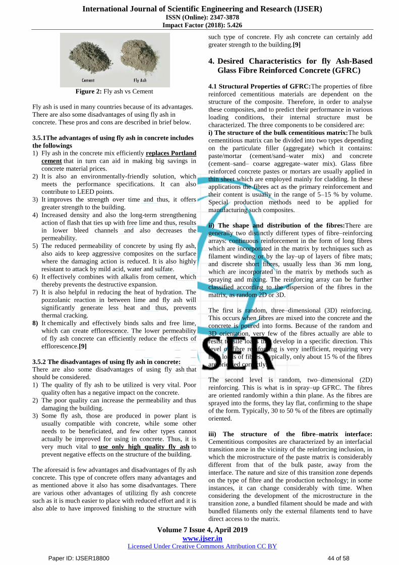
Figure 2: Fly ash vs Cement
Fly ash is used in many countries because of its advantages.
There are also some disadvantages of using fly ash in
concrete. These pros and cons are described in brief below.
3.5.1The advantages of using fly ash in concrete includes
the followings
1) Fly ash in the concrete mix efficiently replaces Portland
cement that in turn can aid in making big savings in
concrete material prices.
2) It is also an environmentally-friendly solution, which
meets the performance specifications. It can also
contribute to LEED points.
3) It improves the strength over time and thus, it offers
greater strength to the building.
4) Increased density and also the long-term strengthening
action of flash that ties up with free lime and thus, results
in lower bleed channels and also decreases the
permeability.
5) The reduced permeability of concrete by using fly ash,
also aids to keep aggressive composites on the surface
where the damaging action is reduced. It is also highly
resistant to attack by mild acid, water and sulfate.
6) It effectively combines with alkalis from cement, which
thereby prevents the destructive expansion.
7) It is also helpful in reducing the heat of hydration. The
pozzolanic reaction in between lime and fly ash will
significantly generate less heat and thus, prevents
thermal cracking.
8) It chemically and effectively binds salts and free lime,
which can create efflorescence. The lower permeability
of fly ash concrete can efficiently reduce the effects of
efflorescence.[9]
3.5.2 The disadvantages of using fly ash in concrete:
There are also some disadvantages of using fly ash that
should be considered.
1) The quality of fly ash to be utilized is very vital. Poor
quality often has a negative impact on the concrete.
2) The poor quality can increase the permeability and thus
damaging the building.
3) Some fly ash, those are produced in power plant is
usually compatible with concrete, while some other
needs to be beneficiated, and few other types cannot
actually be improved for using in concrete. Thus, it is
very much vital to use only high quality fly ash to
prevent negative effects on the structure of the building.
The aforesaid is few advantages and disadvantages of fly ash
concrete. This type of concrete offers many advantages and
as mentioned above it also has some disadvantages. There
are various other advantages of utilizing fly ash concrete
such as it is much easier to place with reduced effort and it is
also able to have improved finishing to the structure with
such type of concrete. Fly ash concrete can certainly add
greater strength to the building.[9]
4. Desired Characteristics for fly Ash-Based
Glass Fibre Reinforced Concrete (GFRC)
4.1 Structural Properties of GFRC:The properties of fibre
reinforced cementitious materials are dependent on the
structure of the composite. Therefore, in order to analyse
these composites, and to predict their performance in various
loading conditions, their internal structure must be
characterized. The three components to be considered are:
i) The structure of the bulk cementitious matrix:The bulk
cementitious matrix can be divided into two types depending
on the particulate filler (aggregate) which it contains:
paste/mortar (cement/sand–water mix) and concrete
(cement–sand– coarse aggregate–water mix). Glass fibre
reinforced concrete pastes or mortars are usually applied in
thin sheet which are employed mainly for cladding. In these
applications the fibres act as the primary reinforcement and
their content is usually in the range of 5–15 % by volume.
Special production methods need to be applied for
manufacturing such composites.
ii) The shape and distribution of the fibres:There are
generally two distinctly different types of fibre–reinforcing
arrays: continuous reinforcement in the form of long fibres
which are incorporated in the matrix by techniques such as
filament winding or by the lay–up of layers of fibre mats;
and discrete short fibres, usually less than 36 mm long,
which are incorporated in the matrix by methods such as
spraying and mixing. The reinforcing array can be further
classified according to the dispersion of the fibres in the
matrix, as random 2D or 3D.
The first is random, three–dimensional (3D) reinforcing.
This occurs when fibres are mixed into the concrete and the
concrete is poured into forms. Because of the random and
3D orientation, very few of the fibres actually are able to
resist tensile loads that develop in a specific direction. This
level of fibre reinforcing is very inefficient, requiring very
high loads of fibres. Typically, only about 15 % of the fibres
are oriented correctly.
The second level is random, two–dimensional (2D)
reinforcing. This is what is in spray–up GFRC. The fibres
are oriented randomly within a thin plane. As the fibres are
sprayed into the forms, they lay flat, confirming to the shape
of the form. Typically, 30 to 50 % of the fibres are optimally
oriented.
iii) The structure of the fibre–matrix interface:
Cementitious composites are characterized by an interfacial
transition zone in the vicinity of the reinforcing inclusion, in
which the microstructure of the paste matrix is considerably
different from that of the bulk paste, away from the
interface. The nature and size of this transition zone depends
on the type of fibre and the production technology; in some
instances, it can change considerably with time. When
considering the development of the microstructure in the
transition zone, a bundled filament should be made and with
bundled filaments only the external filaments tend to have
direct access to the matrix.
Paper ID: IJSER18800 44 of 58

International Journal of Scientific Engineering and Research (IJSER) ISSN (Online): 2347-3878
Impact Factor (2018): 5.426
Volume 7 Issue 4, April 2019
www.ijser.in Licensed Under Creative Commons Attribution CC BY
4.2 Properties of GFRC
Different parameters such as water–cement ratio, porosity,
composite density, inter filler content, fibre content,
orientation and length, and type of cure influence properties
and behaviour of GFRC. GFRC derives its strength from an
optimal dosage of fibres and acrylic polymer. The polymer
and concrete matrix serves to bind the fibres together and
transfer loads from one fibre to another via shear stresses
through the matrix. Density and porosity are effective on the
degree of compaction.
In concrete structure, efficiency of fibres depends upon their
orientation. When the fibres are aligned perpendicular to the
crack openings in the direction of stress, the positive effect
of fibres on the performance of GFRC is increased. Along
with that because of requiring the improvement in the long–
term performance of GFRC the type of glass fibres such as E
and alkali– resistant (AR) glass fibres must also be
considered as well as the environmental conditions. When
alkali attack considered main deterioration mechanism in E
glass, there should be made an attention to seal the fibres
completely from the matrix or used a very low alkali
cementitious material. On the other hand, so as to improve
the alkaline resistance and durability of GFRC with AR
glass fibres, the main effort should be directed modifying the
microstructure of the matrix in the vicinity of the glass
filaments. This could be provided with controlling of the
hydration process in its vicinity or changing the composition
of the matrix.
The rate of ageing is a function of the type of glass fibre.
New generation of AR–glass fibres are better than E glass
ones. The ageing performance of the composite is also
sensitive to the weathering conditions. As the ageing
continues in different environments, chemical attack may
become significant so there is need to develop special glass
fibres for better alkali resistance.
4.3 Mechanical Properties of GFRC:
Addition of fibres to concrete influences its mechanical
properties which significantly depend on the type and
percentage offibre. Fibres with end anchorage and high
aspect ratio were found to have improved effectiveness. It
was shown that for the same length anddiameter, crimped-
endfibres can achieve the samepropertiesas straight fibres
using 40 percent less fibres. In determining the mechanical
properties of GFRC, the same equipment and procedure as
used for conventional concrete can also be used. Below are
cited some properties of FRC determined by different
researchers.
1) Compressive Strength: The compressive strength of
concrete has been increased with the addition of fibres to
concrete mixes, however further addition of fibre
indicated a gradual decrease in strength aspects.The
presence offibres may alter the failure mode ofcylinders,
but the fibre effect will be minor on the improvement
ofcompressive strength values (0 to 15 percent).
2) Modulus of Elasticity: In heterogeneous and multiphase
materials such as concrete, the density and the
characteristics of the transition zone determine the elastic
modulus behaviour of the composite. The experimental
test results exhibit that the use of fibres has no important
influence on the modulus of elasticity of concrete. It was
reported that mostly a little reduction in the modulus of
elasticity of the concrete at a low glass fibre
content.Modulus of elasticity of GFRC increases slightly
with an increase in the fibres content. Itwas found that
for each 1percent increase in fibre content by volume
there is an increase of3 percent in the modulus
ofelasticity.
3) Stress–Strain Curve: Stress-strain behaviour is affected
from different parameters such as the effect of fibre
lengths, aggregate type and effect of loading rate. GFRC
has a significant impact on the ascending portion of the
stress–strain curve and additionally, descending part of
the stress– strain curve is an essential key element under
compression loads.
4) Flexural Strength: Glass fibres have an effect on the
increase in the flexural strength of concrete. The fibres
resist the propagation of cracks and tend to reduce the
sudden failure of structure of concrete and so they lead to
an increase in the load carrying capacity of concrete.The
flexural strength was reportedto be increased by 2.5
times using 4 percent fibres.The use offibres in
reinforced concrete flexure members increases ductility,
tensile strength, moment capacity, and stiffness. The
fibres improve crack control and preserve post cracking
structural integrity of members.
5) Toughness: For GFRC, toughness is about 10 to 40
times that ofplain concrete.
6) Splitting Tensile Strength: The presence of 3 percent
fibre by volume was reported to increase the splitting
tensile strength of mortar about 2.5 times that ofthe
unreinforced one.
7) Fatigue Strength: The addition offibres increases
fatigue strengthofabout 90 percentand 70 percent ofthe
static strength at 2 x 10⁶ cycles for non-reverse and full
reversal ofloading, respectively.
8) Impact Resistance: The impact strength for fibrous
concrete is generally 5 to 10 timesthatofplain concrete
depending on the volume of fibre used.
4.4 Physical Properties of GFRC
i) Drying shrinkage: Drying shrinkage has a significant
effect on the structural and durability performance of the
concrete. The mechanism of shrinkage of cementitious
material is complex, but total shrinkage is principally
affected by the aggregate proportion and type, and
water/cement ratio, having influence on drying and causing
many micro cracks propagation simultaneously. Shrinkage
in concrete structures may also trigger forms of damage in
concrete like as corrosion, freeze damage in this manner,
seriously, shorten the service life of concretes. Alkali–
resistant glass fibres are effective in controlling restrained
shrinkage cracking of concrete and they promote multiple
cracking and reduce crack widths.
ii) Creep: Because of its poor strain capacity and low tensile
strength, concrete is a brittle material and highly susceptible
to cracking. These cracks can decrease the lifetime of a
structure by allowing aggressive agents. Therefore, the
evolution of crack openings through time is important for
the durability of concrete. In terms of creep and shrinkage,
Paper ID: IJSER18800 45 of 58
International Journal of Scientific Engineering and Research (IJSER) ISSN (Online): 2347-3878
Impact Factor (2018): 5.426
Volume 7 Issue 4, April 2019
www.ijser.in Licensed Under Creative Commons Attribution CC BY
application technique of GFRC must be taken into account.
With pneumatic spraying, glass fibre added into mortar
mixture at the time of pouring and there is a significant
modification of the compositions embodied in binder
consumption. This can affect creep strain.
iii) Porosity, Chloride Penetration Resistance and
Electrical Resistivity: Concrete is a multiple–phased
material, and it has lots of micro pores which can be
transferred thanks to the migrating ions. Therefore,
resistivity measurement is a determinative way to explore
the microstructure of concrete. Resistivity of concrete is
influenced by many factors such as water–cement ratio,
concrete composition, admixtures, curing condition,
humidity. As a result, all of these impacts can trigger to
increase the risk of steel rebar corrosion in the concrete.
Along with this, chloride presence in the concrete structure
can increase electrical current and the risk of corrosion.
Alkali resistance GFRC depicts less permeability of chloride
into concrete increasing corrosion resistance. Thus,
durability which is one of the most important aspects of the
concrete, can be improved during working conditions of
concrete structures.
The electrical resistivity of concrete is observed to decrease
with the increase in water–cement ratio.Fibres can play
strong positive result by holding the matrix together even if
it is completely dehydrated process which triggered
possibility of explosion. Addition of polymer materials to
GFRC will affect the fire performance properties.
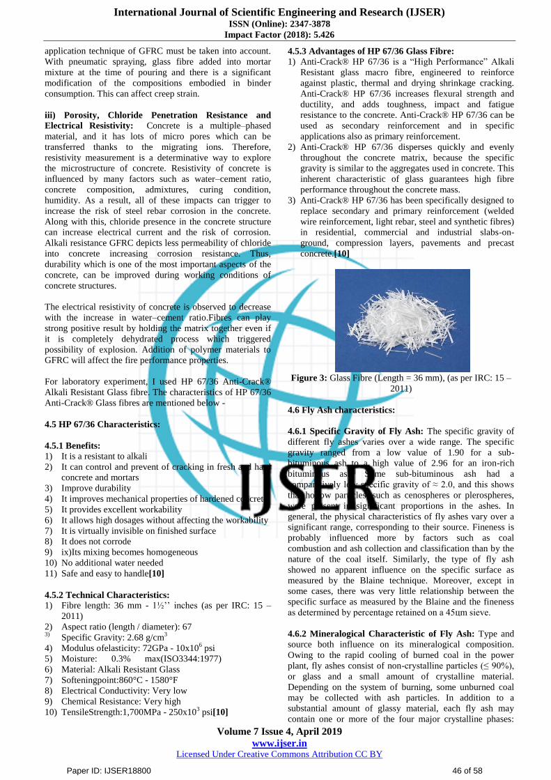
For laboratory experiment, I used HP 67/36 Anti-Crack®
Alkali Resistant Glass fibre. The characteristics of HP 67/36
Anti-Crack® Glass fibres are mentioned below -
4.5 HP 67/36 Characteristics:
4.5.1 Benefits:
1) It is a resistant to alkali
2) It can control and prevent of cracking in fresh and hard
concrete and mortars
3) Improve durability
4) It improves mechanical properties of hardened concrete
5) It provides excellent workability
6) It allows high dosages without affecting the workability
7) It is virtually invisible on finished surface
8) It does not corrode
9) ix)Its mixing becomes homogeneous
10) No additional water needed
11) Safe and easy to handle[10]
4.5.2 Technical Characteristics:
1) Fibre length: 36 mm - 1½‟‟ inches (as per IRC: 15 –
2011)
2) Aspect ratio (length / diameter): 67 3) Specific Gravity: 2.68 g/cm
3
4) Modulus ofelasticity: 72GPa - 10x106 psi
5) Moisture: 0.3% max(ISO3344:1977)
6) Material: Alkali Resistant Glass
7) Softeningpoint:860°C - 1580°F
8) Electrical Conductivity: Very low
9) Chemical Resistance: Very high
10) TensileStrength:1,700MPa - 250x103 psi[10]
4.5.3 Advantages of HP 67/36 Glass Fibre: 1) Anti-Crack® HP 67/36 is a “High Performance” Alkali
Resistant glass macro fibre, engineered to reinforce
against plastic, thermal and drying shrinkage cracking.
Anti-Crack® HP 67/36 increases flexural strength and
ductility, and adds toughness, impact and fatigue
resistance to the concrete. Anti-Crack® HP 67/36 can be
used as secondary reinforcement and in specific
applications also as primary reinforcement.
2) Anti-Crack® HP 67/36 disperses quickly and evenly
throughout the concrete matrix, because the specific
gravity is similar to the aggregates used in concrete. This
inherent characteristic of glass guarantees high fibre
performance throughout the concrete mass.
3) Anti-Crack® HP 67/36 has been specifically designed to
replace secondary and primary reinforcement (welded
wire reinforcement, light rebar, steel and synthetic fibres)
in residential, commercial and industrial slabs-on-
ground, compression layers, pavements and precast
concrete.[10]
Figure 3: Glass Fibre (Length = 36 mm), (as per IRC: 15 –
2011)
4.6 Fly Ash characteristics:
4.6.1 Specific Gravity of Fly Ash: The specific gravity of
different fly ashes varies over a wide range. The specific
gravity ranged from a low value of 1.90 for a sub-
bituminous ash to a high value of 2.96 for an iron-rich
bituminous ash. Some sub-bituminous ash had a
comparatively low specific gravity of ≈ 2.0, and this shows
that hollow particles, such as cenospheres or plerospheres,
were present in significant proportions in the ashes. In
general, the physical characteristics of fly ashes vary over a
significant range, corresponding to their source. Fineness is
probably influenced more by factors such as coal
combustion and ash collection and classification than by the
nature of the coal itself. Similarly, the type of fly ash
showed no apparent influence on the specific surface as
measured by the Blaine technique. Moreover, except in
some cases, there was very little relationship between the
specific surface as measured by the Blaine and the fineness
as determined by percentage retained on a 45цm sieve.
4.6.2 Mineralogical Characteristic of Fly Ash: Type and
source both influence on its mineralogical composition.
Owing to the rapid cooling of burned coal in the power
plant, fly ashes consist of non-crystalline particles (≤ 90%),
or glass and a small amount of crystalline material.
Depending on the system of burning, some unburned coal
may be collected with ash particles. In addition to a
substantial amount of glassy material, each fly ash may
contain one or more of the four major crystalline phases:
Paper ID: IJSER18800 46 of 58
International Journal of Scientific Engineering and Research (IJSER) ISSN (Online): 2347-3878
Impact Factor (2018): 5.426
Volume 7 Issue 4, April 2019
www.ijser.in Licensed Under Creative Commons Attribution CC BY
quartz, mullite, magnetite and hematite. In sub-bituminous
fly ashes, the crystalline phases may include C3A, C4A3S,
calcium sulphate and alkali sulphates. The reactivity of fly
ashes is related to the noncrystalline phase or glass. The
reasons for the high reactivity of high-calcium fly ashes may
partially lie in the chemical composition of the glass. The
composition of glass in low-calcium fly ashes are different
from that is in high-calcium fly ashes.
Table 1: Chemical compounds of Fly Ash
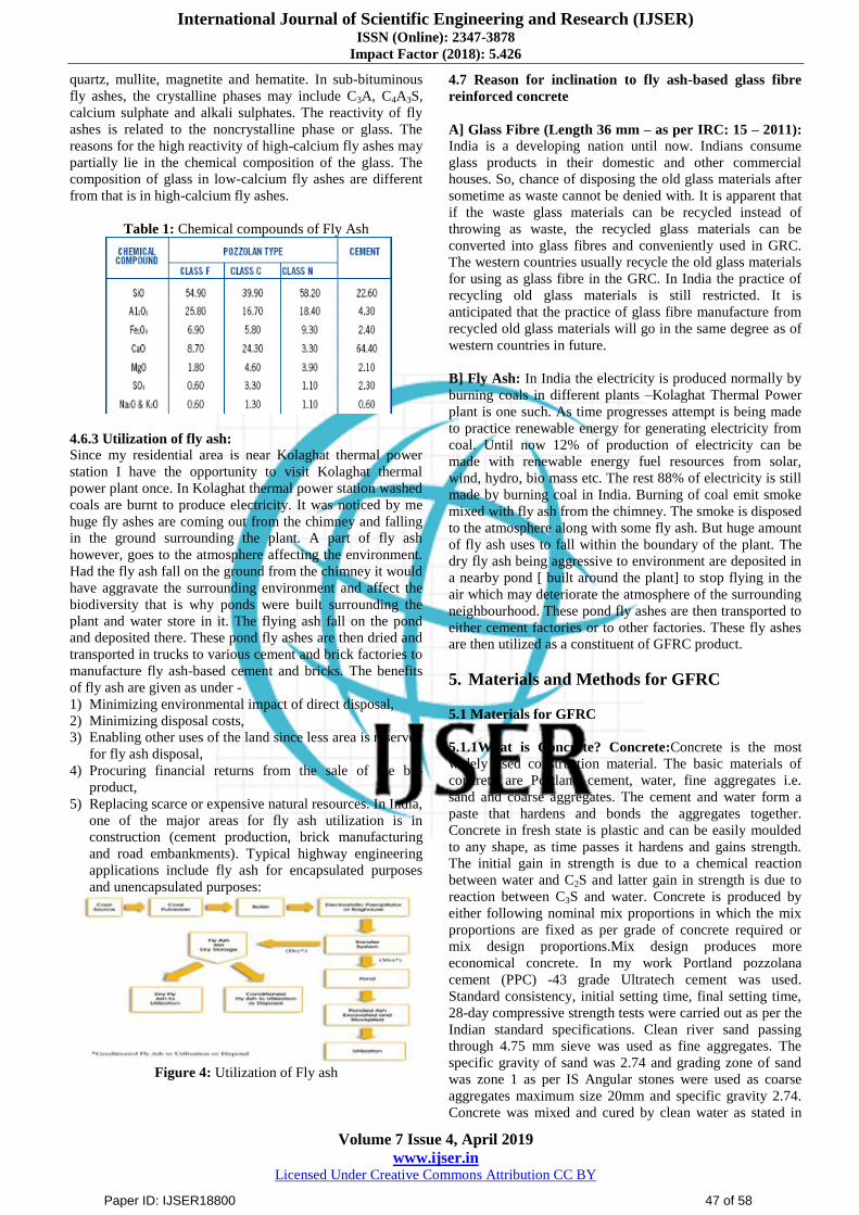
4.6.3 Utilization of fly ash: Since my residential area is near Kolaghat thermal power
station I have the opportunity to visit Kolaghat thermal
power plant once. In Kolaghat thermal power station washed
coals are burnt to produce electricity. It was noticed by me
huge fly ashes are coming out from the chimney and falling
in the ground surrounding the plant. A part of fly ash
however, goes to the atmosphere affecting the environment.
Had the fly ash fall on the ground from the chimney it would
have aggravate the surrounding environment and affect the
biodiversity that is why ponds were built surrounding the
plant and water store in it. The flying ash fall on the pond
and deposited there. These pond fly ashes are then dried and
transported in trucks to various cement and brick factories to
manufacture fly ash-based cement and bricks. The benefits
of fly ash are given as under -
1) Minimizing environmental impact of direct disposal,
2) Minimizing disposal costs,
3) Enabling other uses of the land since less area is reserved
for fly ash disposal,
4) Procuring financial returns from the sale of the by-
product,
5) Replacing scarce or expensive natural resources. In India,
one of the major areas for fly ash utilization is in
construction (cement production, brick manufacturing
and road embankments). Typical highway engineering
applications include fly ash for encapsulated purposes
and unencapsulated purposes:
Figure 4: Utilization of Fly ash
4.7 Reason for inclination to fly ash-based glass fibre
reinforced concrete
A] Glass Fibre (Length 36 mm – as per IRC: 15 – 2011):
India is a developing nation until now. Indians consume
glass products in their domestic and other commercial
houses. So, chance of disposing the old glass materials after
sometime as waste cannot be denied with. It is apparent that
if the waste glass materials can be recycled instead of
throwing as waste, the recycled glass materials can be
converted into glass fibres and conveniently used in GRC.
The western countries usually recycle the old glass materials
for using as glass fibre in the GRC. In India the practice of
recycling old glass materials is still restricted. It is
anticipated that the practice of glass fibre manufacture from
recycled old glass materials will go in the same degree as of
western countries in future.
B] Fly Ash: In India the electricity is produced normally by
burning coals in different plants –Kolaghat Thermal Power
plant is one such. As time progresses attempt is being made
to practice renewable energy for generating electricity from
coal. Until now 12% of production of electricity can be
made with renewable energy fuel resources from solar,
wind, hydro, bio mass etc. The rest 88% of electricity is still
made by burning coal in India. Burning of coal emit smoke
mixed with fly ash from the chimney. The smoke is disposed
to the atmosphere along with some fly ash. But huge amount
of fly ash uses to fall within the boundary of the plant. The
dry fly ash being aggressive to environment are deposited in
a nearby pond [ built around the plant] to stop flying in the
air which may deteriorate the atmosphere of the surrounding
neighbourhood. These pond fly ashes are then transported to
either cement factories or to other factories. These fly ashes
are then utilized as a constituent of GFRC product.
5. Materials and Methods for GFRC
5.1 Materials for GFRC
5.1.1What is Concrete? Concrete:Concrete is the most
widely used construction material. The basic materials of
concrete are Portland cement, water, fine aggregates i.e.
sand and coarse aggregates. The cement and water form a
paste that hardens and bonds the aggregates together.
Concrete in fresh state is plastic and can be easily moulded
to any shape, as time passes it hardens and gains strength.
The initial gain in strength is due to a chemical reaction
between water and C2S and latter gain in strength is due to
reaction between C3S and water. Concrete is produced by
either following nominal mix proportions in which the mix
proportions are fixed as per grade of concrete required or
mix design proportions.Mix design produces more
economical concrete. In my work Portland pozzolana
cement (PPC) -43 grade Ultratech cement was used.
Standard consistency, initial setting time, final setting time,
28-day compressive strength tests were carried out as per the
Indian standard specifications. Clean river sand passing
through 4.75 mm sieve was used as fine aggregates. The
specific gravity of sand was 2.74 and grading zone of sand
was zone 1 as per IS Angular stones were used as coarse
aggregates maximum size 20mm and specific gravity 2.74.
Concrete was mixed and cured by clean water as stated in
Paper ID: IJSER18800 47 of 58

International Journal of Scientific Engineering and Research (IJSER) ISSN (Online): 2347-3878
Impact Factor (2018): 5.426
Volume 7 Issue 4, April 2019
www.ijser.in Licensed Under Creative Commons Attribution CC BY
5.1.4. For casting cubes, cylinders and beams maximum size
of aggregate used was 20mm. The water cement ratio used
for concrete cube and beam was 0.45 and admixture was
used to attain the desire workability.
Figure 5: Concrete laying procedure
5.1.2 Materials for Casting:
The following materials were used in conducting my
experiment in concrete laboratory situated in basement of
Techno India College, Salt Lake Campus.
a) Cement: Portland Pozzolana cement (PPC) – 43 grade
(Ultratech Cement) as stated in clause 5.1.1was used for
the experimental programme. It was tested for its
physical properties in accordance with IS standards.
b) Fine Aggregates: The fine aggregates used for
experimental programme was obtained from bed of river
Koel. The fine aggregates used passed through 4.75mm
sieve and had a specific gravity of 2.74.The fine
aggregates belonged to Zone I according to IS 383 as
stated in clause 5.3.
c) Coarse Aggregates: The coarse aggregates used were
non-reactive and as per the requirements to produce a
good and durable concrete.The coarse aggregates were of
two different grading of 20 mm and 10 mm sizes were
used to prepare the mix.
d) Water: Clean water which is safe and potable for
drinking was used for producing all types of mix.
e) Flyash: Fly ash class F were used for laboratory
experiment. The Fly Ash used in replacement of cement
in concrete is brought from Kolaghat Thermal Power
Station near Mecheda.
f) Glass Fibres (Length 36 mm – as per IRC 15 –
2011):Glass fibre also known as fibreglass is made from
extremely fine fibres of glass. It is a light weight,
extremely strong and a robust material. Glass fibres are
relatively less stiff and made from relatively less
expensive material as compared to carbon fibres. It is
less brittle and also has lower strength than carbon fibres.
In my case AR-HP 67/36 glass fibres were used. The
glass fibres used had a specific gravity of 2.68 gm/cm3,
tensile strength 1700 MPa and Young‟s Modulus 72GPa.
5.2 Methods
I have taken sample concrete cubes of size
150mm×150mm×150mm for testing the compressive
strength of the product. Additionally, I have taken the
sample of concrete beam in regard to obtain the flexural
strength of the concrete product.
The list of equipment‟s used in the laboratory by me are –
1) Balance with different capacities (digital)
2) Motorised Sieve shaker
3) Laboratory concrete mixtures
4) Needle vibrators
5) Curing tanks
6) Compression testing machine electrically operated
7) Universal testing machine
8) Flexural testing machine
9) Oven
10) Slump test apparatus
11) Vicat apparatus
12) Le chateleir apparatus
13) Mould (150mm×150mm×150mm)
14) Gauging trowel
15) Tamping rod
16) Beam mould
(100mm×100mm×500mm),(150mm×150mm×700mm)
17) Cylindrical mould (150mm×300mm)
18) Aluminium boxes for measuring moisture contents
19) Specific gravity bottle
20) Bulk density voids and bulking apparatus
21) Metal tray
22) Measuring cylinders (25-1000ml capacity)
23) IS Sieve set 20 cm diameter, brass made, 10mm – 38
microns with pan & cover
24) IS Sieve set 45 cm diameter, GI made, 40mm-2.36mm
with pan & cover
Various tests conducted on the specimens are described
below along with the description and importance. The
investigation was carried out for casting of cubes, beams and
the grade of concrete was M-20. The materials of the
concrete were described in the clause 5.1.8. The nominal
maximum size of coarse aggregate was 20mm.
5.3 Form Work
Form work may be defined as a temporary structure or a
permanent structure used to contain poured concrete in fresh
state. The form work which is removed after placing
concrete and getting it hardened is called a temporary
formwork. But sometimes form work used in slender
columns with stiffness value very low where steel plated
formwork is used which is kept permanently after concreting
and hardening so that there is no chance of appearing major
cracks in the column section due to opening of the
formwork. Fresh concrete is plastic and can be easily
moulded in formwork. Formwork plays an important role in
shaping the concrete and supporting it while gaining
sufficient strength to support itself. It is required that the
formwork be sufficiently strong to take the dead load and
live load that may come upon it during construction and also
it should be sufficiently rigid at the same time to avoid
bulging, twisting, swaging due to these loads. Dead loads are
the weight of the formwork along with the weight of the
fresh concrete. The live loads may be taken as the weight of
the workers, equipment‟s, runways and material storage and
compacting equipment‟s. In our case permanent moulds
were used which are commercially available in market.
However, for preparation of beams, moulds were specially
ordered and procured from local steel fabricating shops.
5.4 Mixing of Concrete
Concrete can be prepared either by hand mixing or machine
mixing. Hand mixing can be done in a plane levelled surface
such as a wooden platform or a paved concrete surface
Paper ID: IJSER18800 48 of 58

International Journal of Scientific Engineering and Research (IJSER) ISSN (Online): 2347-3878
Impact Factor (2018): 5.426
Volume 7 Issue 4, April 2019
www.ijser.in Licensed Under Creative Commons Attribution CC BY
having tight jointsto prevent loss of water due to hydration.
To do hand mixing the levelled surface is cleaned first and
then moistened by spraying water. Sand is then poured on
the surface. After putting sand covering the full area of the
level surface cement is then spread over the sand. Cement
and sand are then mixed thoroughly before putting coarse
aggregates into the uniform mix of cement and sand. For
mixing materials either a hoe or a square-pointed D-handled
shovel is used. Cement, fine and coarse aggregates are
mixed thoroughly up to time, the colour of the mixture is
uniform throughout. Then glass fibre and fly ash are added
to the mix as per calculation on percentage of the total
weight of the mix. Then again, all the materials including fly
ash and glass fibres mixed thoroughly. Then water is slowly
added.The dry mix materials along with the admixtures are
turned ¾ times for getting a uniform mix. The fresh concrete
produced from the uniform mix is plastic in nature which
can be moulded in the formwork as per our needs.
In my investigation hand mixing was used because the
machine drum mixture was not cleaned and it was difficult
to clean the drum.
In case of machine mixing, machine drum must be clean and
wrapped with a clean cloth and then moistened to prevent
any loss of water during hydration. All the dry materials
along with glass fibres and fly ash are put in the drum and
then mixed thoroughly by rotating drum. After water is
added in the drum and mixed again up to the time the
uniform coloured mix is obtained. After completing all the
process concrete slurry is dropped from the drum on a flat
and clean steel plate (good timber also will do), from where
slurry is taken and put in the formwork as needed for
concreting.
Figure 6 & 7: Different methods of concrete mixing
5.5 Compaction
Compaction of concrete is the methodology to expel the
entrapped air from the concrete. During mixing,
transportation and pouring the concrete in the formwork,
outside air use to entered into the concrete. The amount of
air will be higher for lower workability. Such air need to be
removed fully so that the concrete does not loseits strength
considerably. The relationship between the percentage of
losing strength and percentage of air voids due to deficit of
compaction is shown in the figure below –
Figure 8: Relationship between loss of strength and air-void
space
It is observed at site of concreting that 5% air voids reduce
the strength of concrete by about 30% and 10% air voids
reduce the strength by 50%. So, compaction of concrete
raises an important and virtual role in making a good dense
and durable concrete.
To achieve the optimum compaction with maximum density
the following compacting process are normally adopted. The
concrete mix should not be too wet to compact easily but
with reduced strength of concrete. For maximum strength,
concrete should be compacted by 100% with a reasonable
compacting equipment available in the site. The following
methods are adopted for compacting the concrete –
(a)Hand Compaction
(i)Rodding
(ii)Ramming
(iii)Tamping
(b)Compaction by vibration
(i)Internal vibrator (Needle vibrator)
(ii)Formwork vibrator (External vibrator)
(iii)Table vibrator
(iv)Platform vibrator
(v)Surface vibrator (Screed vibrator)
(vi)Vibratory Roller
(c)Compaction by Pressure and Jolting
(d)Compaction by Spinning
(i)Hand Compaction:
Hand compaction of concrete is practiced in case of less
important concrete product and where the concrete is
prepared in small quantity. Sometimes hand method is
needed where there is congestion of reinforcement (as
required as per design) which cannot be comfortably
compacted mechanically. Hand compaction consist of
rodding, ramming and/or tamping. In hand compaction the
consistency of concrete is maintained at higher level. The
thickness of the layer of concrete is limited to about 15 to 20
cm. The concrete is poked with a 2 m long and 16 mm
diameter rod.It is used to pack the concrete between the
reinforcement and sharp corners and edges. Rodding is done
over the complete area of concrete to drive away the
entrapped air and making the concrete dense. Ramming is
not generally permitted in case of upper floor construction
where concrete is placed in the formwork supported on
Paper ID: IJSER18800 49 of 58
International Journal of Scientific Engineering and Research (IJSER) ISSN (Online): 2347-3878
Impact Factor (2018): 5.426
Volume 7 Issue 4, April 2019
www.ijser.in Licensed Under Creative Commons Attribution CC BY
struts. If the process of ramming is used in such case the
position of the reinforcement may be disturbed resulting in
the formwork may fall.
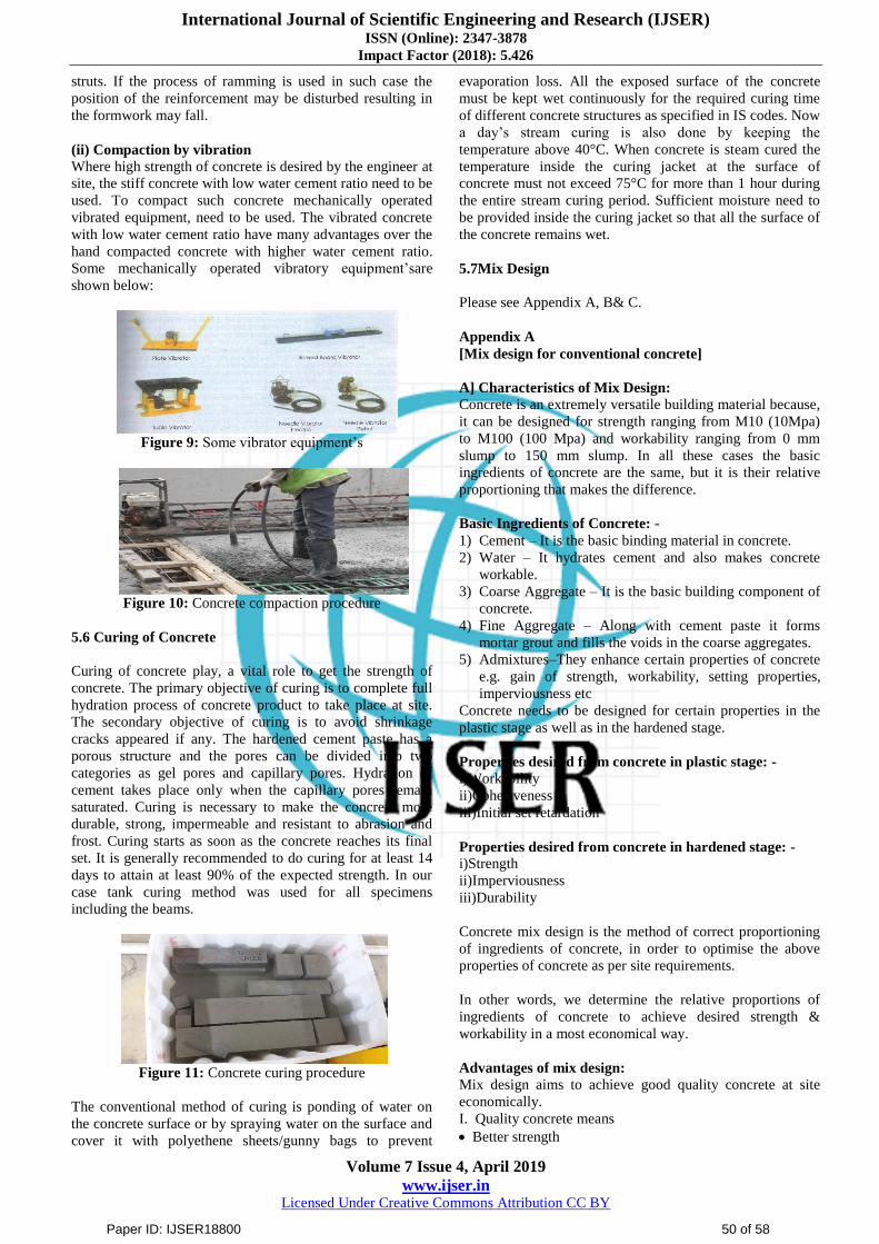
(ii) Compaction by vibration
Where high strength of concrete is desired by the engineer at
site, the stiff concrete with low water cement ratio need to be
used. To compact such concrete mechanically operated
vibrated equipment, need to be used. The vibrated concrete
with low water cement ratio have many advantages over the
hand compacted concrete with higher water cement ratio.
Some mechanically operated vibratory equipment‟sare
shown below:
Figure 9: Some vibrator equipment‟s
Figure 10: Concrete compaction procedure
5.6 Curing of Concrete
Curing of concrete play, a vital role to get the strength of
concrete. The primary objective of curing is to complete full
hydration process of concrete product to take place at site.
The secondary objective of curing is to avoid shrinkage
cracks appeared if any. The hardened cement paste has a
porous structure and the pores can be divided into two
categories as gel pores and capillary pores. Hydration of
cement takes place only when the capillary pores remain
saturated. Curing is necessary to make the concrete more
durable, strong, impermeable and resistant to abrasion and
frost. Curing starts as soon as the concrete reaches its final
set. It is generally recommended to do curing for at least 14
days to attain at least 90% of the expected strength. In our
case tank curing method was used for all specimens
including the beams.
Figure 11: Concrete curing procedure
The conventional method of curing is ponding of water on
the concrete surface or by spraying water on the surface and
cover it with polyethene sheets/gunny bags to prevent
evaporation loss. All the exposed surface of the concrete
must be kept wet continuously for the required curing time
of different concrete structures as specified in IS codes. Now
a day‟s stream curing is also done by keeping the
temperature above 40°C. When concrete is steam cured the
temperature inside the curing jacket at the surface of
concrete must not exceed 75°C for more than 1 hour during
the entire stream curing period. Sufficient moisture need to
be provided inside the curing jacket so that all the surface of
the concrete remains wet.
5.7Mix Design
Please see Appendix A, B& C.
Appendix A
[Mix design for conventional concrete]
A] Characteristics of Mix Design:
Concrete is an extremely versatile building material because,
it can be designed for strength ranging from M10 (10Mpa)
to M100 (100 Mpa) and workability ranging from 0 mm
slump to 150 mm slump. In all these cases the basic
ingredients of concrete are the same, but it is their relative
proportioning that makes the difference.
Basic Ingredients of Concrete: -
1) Cement – It is the basic binding material in concrete.
2) Water – It hydrates cement and also makes concrete
workable.
3) Coarse Aggregate – It is the basic building component of
concrete.
4) Fine Aggregate – Along with cement paste it forms
mortar grout and fills the voids in the coarse aggregates.
5) Admixtures–They enhance certain properties of concrete
e.g. gain of strength, workability, setting properties,
imperviousness etc
Concrete needs to be designed for certain properties in the
plastic stage as well as in the hardened stage.
Properties desired from concrete in plastic stage: -
i)Workability
ii)Cohesiveness
iii)Initial set retardation
Properties desired from concrete in hardened stage: -
i)Strength
ii)Imperviousness
iii)Durability
Concrete mix design is the method of correct proportioning
of ingredients of concrete, in order to optimise the above
properties of concrete as per site requirements.
In other words, we determine the relative proportions of
ingredients of concrete to achieve desired strength &
workability in a most economical way.
Advantages of mix design:
Mix design aims to achieve good quality concrete at site
economically.
I. Quality concrete means
Better strength
Paper ID: IJSER18800 50 of 58

International Journal of Scientific Engineering and Research (IJSER) ISSN (Online): 2347-3878
Impact Factor (2018): 5.426
Volume 7 Issue 4, April 2019
www.ijser.in Licensed Under Creative Commons Attribution CC BY
Better imperviousness and durability
Dense and homogeneous concrete
II. Economy of mix design:
Economy in cement consumption: It is possible to save up
to 15% of cement for M20 grade of concrete with the help
of concrete mix design. In fact, higher the grade of
concrete more are the savings. Lower cement content also
results in lower heat of hydration and hence reduces
shrinkage cracks.
Best use of available materials: Site conditions often
restrict the quality and quantity of ingredient materials.
Concrete mix design offers a lot of flexibility on type of
aggregates to be used in mix design. Mix design can give
an economical solution based on the available materials if
they meet the basic IS requirements. This can lead to
saving in transportation costs from longer distances.
Other properties: Mix design can help us to achieve form
finishes, high early strengths for early deshuttering,
concrete with better flexural strengths, concrete with
pumpability and concrete with lower densities.
B] Calculation:
Design Stipulations:
i) Grade of concrete (designation)= M20
ii) Type of cement = PPC 43 grade
iii) Minimum nominal size of aggregate = 20 mm
iv) Workability = 25 – 50 mm
(slump)
v) Exposure condition = mild
vi) Method of concrete placing = normal
vii) Degree of supervision = good
viii) Specific gravity of cement = 3.15
ix) Specific gravity of coarse aggregate= 2.74
x) Specific gravity of fine aggregate = 2.74
xi) Sieve analysis= zone 1 (IS 383 – 1970)
DESIGN:
Step 1: Target mean strength
fck‟= fck + 1.65s From Table 1 of IS 10262 - 2009
= 20 + 1.65 × 4 standard deviation, s = 4N/mm2
fck‟ = 26.6 N/mm2
Step 2: Selection of water cement ratio
From Table 5 of IS 456 – 2000
For M20 concrete, maximum w/c ratio = 0.5
Based on experience adopt water cement ratio = 0.45
0.45<0.50
Step 3: Selection of water content
From Table 2 of IS 10262:2009 maximum water content for
20 mm aggregate =186 litre (for 25 to 50 mm slump range)
Step 4: Calculation of cement content
Water-cement ratio = 0.45
Cement content= 186/0.45 = 413.33 kg/m3
From Table 5 ofIS 456-2000,
Minimum cement content for 'severe' exposure condition =
300 kg/m3
413.33 kg/m3> 300 kg/m
3, hence O.K.
Step 5: Proportion of volume of coarse aggregate and
fine aggregate content
From Table 3 volume of coarse aggregate corresponding to
20 mm size aggregate and fine aggregate (Zone I) for water-
cement ratio of 0.50 =0.60.
In the present case water-cement ratio is 0.45. Therefore,
volume of coarse aggregate is required to be increased to
decrease the fine aggregate content. As the water-cement
ratio is lower by 0.10 the proportion of volume of coarse
aggregate is increased by 0.02 (at the rate of -/+ 0.01 for
every ± 0.05 change in water-cement ratio). Therefore,
corrected proportion of volume of coarse aggregate for the
water-cement ratio of 0.45 = 0.61.
NOTE - In case the coarse aggregate is not angular one then
also volume of coarse aggregate may be required 10 be
increased suitably, based on experience.
Therefore, volume ofcoarse aggregate = 0.61
Volume of fine aggregate content=1 - 0.61 =0.39.
Step 6: Mix calculations
The mix calculations per unit volume of concrete shall be as
follows:
a)Volume of concrete = 1 m3
b) Volume of cement = (Mass of cement/Specific gravity of
cement) × (1/1000)
= (413.33/3.15) × (1/1000) [For w/c ratio = 0.45]
= 0.131 m3
c) Volume of water = (Mass of water/Specific gravity of
water) × (1/1000)
= (186/1) × (1/1000)
= 0.186m3
d) Volume of all in aggregate = {a-(b+c)}
= 1 – (0.131 + 0.186)
=0.683 m3
e) Mass of coarse aggregate = (d x Volume of coarse
aggregate x Specific gravity of coarse aggregate x 1000)
= 0.683 x 0.61 x 2.74 x 1000
= 1141.57 kg
f) Mass of fine aggregate = (d x Volume of fine aggregate
x Specific gravity of fine aggregate x 1000)
= 0.683 x 0.39 x 2.74 x 1000
= 729.85 kg
Step 7: Mix proportions for trial number 1
Cement = 413 kg
Water = 186 kg/m3
Fine aggregate = 730 kg
Coarse aggregate = 1142 kg
Water-cement ratio = 0.45
NOTE –(i)Aggregates should be used in saturated surface
dry condition. If otherwise when computing the requirement
of mixing water, allowance shall be made for the free
(surface) moisture contributed by the fine and coarse
aggregates. On the other hand, if the aggregates are dry, the
amount of mixing water should be increased by an amount
equal to the moisture likely to be absorbed by the
aggregates. Necessary adjustments are also required to be
made in mass of aggregates. The surface water and percent
of water absorption of aggregates shall be determined
according to IS 2386.
Paper ID: IJSER18800 51 of 58

International Journal of Scientific Engineering and Research (IJSER) ISSN (Online): 2347-3878
Impact Factor (2018): 5.426
Volume 7 Issue 4, April 2019
www.ijser.in Licensed Under Creative Commons Attribution CC BY
(ii)The slump shall be measured and the water content and
dosage of admixture shall be adjusted for achieving the
required slump based on trial, if required. The mix
proportions shall be reworked for the actual water content
and checked for durability requirements.
(iii)Two more trials having variation of ±10percent of water-
cement ratio in (ii) shall be carried out and a graph between
three water-cement ratios and their corresponding strengths
shall be plottedto work out the mix proportions for the given
target strength for field trials. However, durability
requirement shall be met.
Appendix – B
[For high volume fly ash-based glass fibre reinforced
concrete (with OPC)]
A] Characteristics of Mix Design:
Same as in Appendix A and as given in Chapter 4.
B] Calculation:
Design Stipulations:
i) Grade of concrete (designation) = M20
ii) Type of cement = OPC 43 grade
iii) Minimum nominal size of aggregate = 20 mm
iv) Workability = 25 – 50 mm
(slump)
v) Exposure condition = mild
vi) Method of concrete placing = normal
vii) Degree of supervision = good
viii) Specific gravity of cement = 3.15
ix) Specific gravity of coarse aggregate = 2.74
x) Specific gravity of fine aggregate = 2.74
xi) Sieve analysis = zone 1 (IS 383 – 1970)
Design:
Step 1: Target mean strength
fck‟= fck + 1.65s From Table 1 of IS 10262 - 2009
= 20 + 1.65 ×4 standard deviation, s = 4
fck‟ = 26.6 N/mm2
Step 2: Selection of water cement ratio
From Table 5 of IS 456 – 2000
For M20 concrete, maximum w/c ratio = 0.5
Based on experience adopt water cement ratio = 0.45
0.45<0.50 hence ok.
Step 3: Selection of water content
From Table 2 of IS 10262:2009 maximum water content for
20 mm aggregate =186 kg/m3 (for 25 to 50 mm slump
range)
Maximum water content for 20 mm aggregate =186 kg/m3
[for 25 to 50 mm slump]
Step 4: Calculation of cement and fly ash content:
Water-cement ratio = 0.45
Cement content= 186/0.45 = 413.33 kg/m3
From Table 5 ofIS 456-2000,
Minimum cement content for 'severe' exposure condition =
300 kg/m3
413.33 kg/m3> 300 kg/m
3, hence, O.K.
From Table 5 of IS 456:2000
Minimum cement content for „mild‟ exposure condition =
300 kg/m3
Above cement content value is > 300 kg/m3(Hence ok)
Note: This illustration example is with increase of 10
percent cementitious material content.
Cementitious material content = 413.33 × 1.10 = 454.66
kg/m3 ≈ 455 kg/m
3
Water content = 186 kg/m3
So, water cement ratio = 186/455 = 0.4088 ≈ 0.41
Fly ash @ 50% of total cementitious material content = 455
×50% = 227.5 kg/m3
Cement (OPC) = 456 – 228 = 228 kg/m3
Fly ash being utilized = 228 kg/m3
Saving of cement while using fly ash = 413 – 228 = 185
kg/m3
Step5: Proportion of volume of coarse aggregate and fine
aggregate content:
From Table 3 volume of coarse aggregate corresponding to
20 mm size aggregate and fine aggregate (Zone I) for water-
cement ratio of 0.50 =0.60.
In the present case water-cement ratio is 0.45. Therefore,
volume of coarse aggregate is required to be increased to
decrease the fine aggregate content. As the water-cement
ratio is lower by 0.10 the proportion of volume of coarse
aggregate is increased by 0.02 (at the rate of -/+ 0.01 for
every ± 0.05 change in water-cement ratio). Therefore,
corrected proportion of volume of coarse aggregate for the
water-cement ratio of 0.45 = 0.61.
NOTE - In case the coarse aggregate is not angular one then
also volume of coarse aggregate may be required 10 be
increased suitably, based on experience.
Therefore, volume ofcoarse aggregate = 0.61
Volume of fine aggregate content=1 - 0.61 =0.39.
Step 6: Mix calculations:
The mix calculations per unit volume of concrete shall be as
follows:
a)Volume of concrete = 1 m3
b) Volume of cement = (Mass of cement/Specific gravity of
cement) × (1/1000)
= (228/3.15) × (1/1000)
= 0.072 m3
c) Volume of fly ash = (Mass of fly ash/Specific gravity of
fly ash) × (1/1000)
= (228/2.2) × (1/1000)
= 0.104 m3
d) Volume of water = (Mass of water/Specific gravity of
water) × (1/1000)
= (186/1) × (1/1000)
= 0.186 m3
e) Volume of all in aggregate = {a-(b+c+d)}
= 1 – (0.072 + 0.104+0.186)
=0.638 m3
f) Mass of coarse aggregate = (e x Volume of coarse
aggregate x Specific gravity of coarse aggregate x 1000)
= 0.638 x 0.61 x 2.74 x 1000
= 1066 kg
g) Mass of fine aggregate = (e x Volume of fine aggregate x
Specific gravity of fine aggregate x 1000)
= 0.638 x 0.39 x 2.74 x 1000
= 682 kg
h) Mass of glass fibres = According to clause 3.8 of IRC 15
– 2011
Paper ID: IJSER18800 52 of 58

International Journal of Scientific Engineering and Research (IJSER) ISSN (Online): 2347-3878
Impact Factor (2018): 5.426
Volume 7 Issue 4, April 2019
www.ijser.in Licensed Under Creative Commons Attribution CC BY
Suggested dosage = 0.6 to 2.0 kg/m3(0.2 to 0.6 percent by
weight of cement in mix)
So, 0.6 percent of cementitious product = (0.6/100) × 456 =
2.74 kg/m3
Step 7: Mix proportions for trial number 1
Cement (OPC) = 228 kg/m3
Fly ash = 228 kg/m3
Water = 186 kg/m3
Fine aggregate = 682 kg/m3
Coarse aggregate = 1066 kg/m3
Water-cement ratio = 0.41
Glass Fibre = 2.74 kg/m3
Note –
(i)Aggregates should be used in saturated surface dry
condition. If otherwise when computing the requirement of
mixing water, allowance shall be made for the free (surface)
moisture contributed by the fine and coarse aggregates. On
the other hand, if the aggregates are dry, the amount of
mixing water should be increased by an amount equal to the
moisture likely to be absorbed by the aggregates. Necessary
adjustments are also required to be made in mass of
aggregates. The surface water and percent of water
absorption of aggregates shall be determined according to IS
2386.
(ii)The slump shall be measured and the water content and
dosage of admixture shall be adjusted for achieving the
required slump based on trial, if required. The mix
proportions shall be reworked for the actual water content
and checked for durability requirements.
(iii)Two more trials having variation of ±10percent of water-
cement ratio in (ii) shall be carried out and a graph between
three water-cement ratios and their corresponding strengths
shall be plottedto work out the mix proportions for the given
target strength for field trials. However, durability
requirement shall be met.[11][12][13]
Appendix – C[For high volume fly ash-based glass fibre
reinforced concrete (with PPC)]
A] Characteristics of Mix Design:Same as in Appendix A
and as given in Chapter 4.
B] Calculation:Design Stipulations:
i) Grade of concrete (designation) = M20
ii) Type of cement = PPC 43 grade
iii) Minimum nominal size of aggregate = 20 mm
iv) Workability = 25 – 50 mm (slump)
v) Exposure condition = mild
vi) Method of concrete placing = normal
vii) Degree of supervision = good
viii) Specific gravity of cement = 3.15
ix) Specific gravity of coarse aggregate = 2.74
x) Specific gravity of fine aggregate = 2.74
xi) Sieve analysis = zone 1 (IS 383 – 1970)
Design:
Step 1: Target mean strength
fck‟= fck + 1.65s From Table 1 of IS 10262 - 2009
= 20 + 1.65 ×4 standard deviation, s = 4
fck‟ = 26.6 N/mm2
tep 2: Selection of water cement ratio
From Table 5 of IS 456 – 2000
For M20 concrete, maximum w/c ratio = 0.5
Based on experience adopt water cement ratio = 0.45
0.45<0.50 hence ok.
Step 3: Selection of water content
From Table 2 of IS 10262:2009 maximum water content for
20 mm aggregate =186 kg/m3 (for 25 to 50 mm slump
range)
Maximum water content for 20 mm aggregate =186 kg/m3
[for 25 to 50 mm slump]
Step 4: Calculation of cement and fly ash content:
Water-cement ratio = 0.45
Cement content= 186/0.45 = 413.33 kg/m3
From Table 5 of IS 456-2000,
Minimum cement content for 'severe' exposure condition =
300 kg/m3
413.33 kg/m3 > 300 kg/m
3, hence, O.K.
From Table 5 of IS 456:2000
Minimum cement content for „mild‟ exposure condition =
300 kg/m3
Above cement content value is > 300 kg/m3 (Hence ok)
Note: This illustration example is with increase of 10
percent cementitious material content.
Cementitious material content = 413.33 × 1.10 = 454.66
kg/m3 ≈ 455 kg/m
3
Water content = 186 kg/m3
So, water cement ratio = 186/455 = 0.4088 ≈ 0.41
Fly ash @ 30% of total cementitious material content = 455
×30% = 136.5 kg/m3 ≈137 kg/m
3
Cement (OPC) = 455 – 137 = 318 kg/m3
Fly ash being utilized = 137 kg/m3
Saving of cement while using fly ash = 413 – 318 = 95
kg/m3
Step5: Proportion of volume of coarse aggregate and fine
aggregate content:
From Table 3 volume of coarse aggregate corresponding to
20 mm size aggregate and fine aggregate (Zone I) for water-
cement ratio of 0.50 =0.60.
In the present case water-cement ratio is 0.45. Therefore,
volume of coarse aggregate is required to be increased to
decrease the fine aggregate content. As the water-cement
ratio is lower by 0.10 the proportion of volume of coarse
aggregate is increased by 0.02 (at the rate of -/+ 0.01 for
every ± 0.05 change in water-cement ratio). Therefore,
corrected proportion of volume of coarse aggregate for the
water-cement ratio of 0.45 = 0.61.
NOTE - In case the coarse aggregate is not angular one then
also volume of coarse aggregate may be required 10 be
increased suitably, based on experience.
Therefore, volume of coarse aggregate = 0.61
Volume of fine aggregate content=1 - 0.61 =0.39.
Step 6: Mix calculations:
The mix calculations per unit volume of concrete shall be as
follows:
a)Volume of concrete = 1 m3
Paper ID: IJSER18800 53 of 58

International Journal of Scientific Engineering and Research (IJSER) ISSN (Online): 2347-3878
Impact Factor (2018): 5.426
Volume 7 Issue 4, April 2019
www.ijser.in Licensed Under Creative Commons Attribution CC BY
b) Volume of cement = (Mass of cement/Specific gravity of
cement) × (1/1000)
= (318/3.15) × (1/1000)
= 0.101 m3
c) Volume of fly ash = (Mass of fly ash/Specific gravity of
fly ash) × (1/1000)
= (137/2.2) × (1/1000)
= 0.062 m3
d) Volume of water = (Mass of water/Specific gravity of
water) × (1/1000)
= (186/1) × (1/1000)
= 0.186 m3
e) Volume of all in aggregate = {a-(b+c+d)}
= 1 – (0.101 + 0.062 +0.186)
=0.651 m3
f) Mass of coarse aggregate = (e x Volume of coarse
aggregate x Specific gravity of coarse aggregate x 1000)
= 0.651 x 0.61 x 2.74 x 1000
= 1088 kg
g) Mass of fine aggregate = (e x Volume of fine aggregate x
Specific gravity of fine aggregate x 1000)
= 0.651 x 0.39 x 2.74 x 1000
= 696 kg
h) Mass of glass fibres = According to clause 3.8 of IRC 15
– 2011
Suggested dosage = 0.6 to 2.0 kg/m3 (0.2 to 0.6 percent by
weight of cement in mix)
So, 0.6 percent of cementitious product = (0.6/100) × 456 =
2.74 kg/m3
Step 7: Mix proportions for trial number 1
Cement(PPC) = 318 kg/m3
Fly ash = 137 kg/m3
Water = 186 kg/m3
Fine aggregate = 696 kg/m3
Coarse aggregate = 1088 kg/m3
Water-cement ratio = 0.41
Glass Fibre = 2.74 kg/m3
Note –
(i)Aggregates should be used in saturated surface dry
condition. If otherwise when computing the requirement of
mixing water, allowance shall be made for the free (surface)
moisture contributed by the fine and coarse aggregates. On
the other hand, ifthe aggregates are dry, the amount of
mixing water should be increased by an amount equal to the
moisture likely to be absorbed by the aggregates. Necessary
adjustments are also required to be made in mass of
aggregates. The surface water and percent of water
absorption of aggregates shall be determined according to IS
2386.
(ii)The slump shall be measured and the water content and
dosage of admixture shall be adjusted for achieving the
required slump based on trial, if required. The mix
proportions shall be reworked for the actual water content
and checked for durability requirements.
(iii)Two more trials having variation of ±10 percent of
water-cement ratio in (ii) shall be carried out and a graph
between three water-cement ratios and their corresponding
strengths shall be plotted to work out the mix proportions for
the given target strength for field trials. However, durability
requirement shall be met. [11] [12] [13]
6. Results and Discussion
For testing of glass fibre reinforced concrete, it is required to
cast the various moulds like cubes and beams. It is cured for
the required period after 24 hrs of casting.
6.1 My pre-submission work
I did my preliminary laboratory work in regard to testing of
cubes of size 150mm×150mm×150mm and plain concrete
beams of sizes 100mm×100mm×500mm &
150mm×150mm×700mm. For this work I have taken the
guidance of Prof Gaurav Ghosh. I prepared concrete slurry
for the above work in the concrete laboratory situated in
basement of Techno India College, Salt Lake Campus. The
constituents of all ingredients had been mixed in hand
machine adding the required quantity of pure water at 4℃.
Figure 12: Selfie taken by me on 12.09.18 while cube &
beam casting & curing
6.2 The specimens cast as follows:
Initially the mould is applied with oil for lubrication.
Concrete is laid in the mould. Concrete has been filled in
both the Cube Specimens &Beam Specimens. The results
obtained from the detailed experimental program conducted
on M20 grade Fly Ash based Glass Fibre Reinforced
concrete are presented below.
6.3 Compressive Strength of Concrete (in N/mm2)
The 7 days, 28 days, 56 days and 90 days compressive
strength was studied and the values of 3 samples on 7 days,
28 days, 56 days and 90 days studied are shown in the
tabular form.Table6 shows the data of 7 days, 28 days, 56
days and 90 days compressive strength obtained.
Table6gives the compressive strength of concrete with
maximum nominal size of aggregates20mm.The 7 days,28
days, 56 days and 90 days compressive strength was also
plotted in Fig27 by taking the average of these three values
with addition of fibres.
Table 2: Compressive Strength
Sr No. Cube
Specification
Grade
of
concrete
Age of
specimen
in days
Dimension of
specimen in
cm
Cross sectional
area of
specimen in
cm2
Actual
crushing load
in Kg
Comp.
strength in
Kg/cm2
Average comp.
strength in
Kg/cm2
Specified limit for
days Kg/cm2
7 days 28 days
Paper ID: IJSER18800 54 of 58

International Journal of Scientific Engineering and Research (IJSER) ISSN (Online): 2347-3878
Impact Factor (2018): 5.426
Volume 7 Issue 4, April 2019
www.ijser.in Licensed Under Creative Commons Attribution CC BY
1 1 M 20 7 15 × 15 × 15 225 31500 140.00
142.22
2 2 M 20 7 15 × 15 × 15 225 32500 144.44 M20 M20
3 3 M 20 7 15 × 15 × 15 225 32000 142.22 135 200
4 1 M 20 28 15 × 15 × 15 225 46500 206.67
208.89 5 2 M 20 28 15 × 15 × 15 225 47500 211.11
6 3 M 20 28 15 × 15 × 15 225 47000 208.89
7 1 M 20 56 15 × 15 × 15 225 50000 222.22
223.70 8 2 M 20 56 15 × 15 × 15 225 51000 226.67
9 3 M 20 56 15 × 15 × 15 225 50000 222.22
10 1 M 20 90 15 × 15 × 15 225 53500 237.78
237.04 11 2 M 20 90 15 × 15 × 15 225 53500 237.78
12 3 M 20 90 15 × 15 × 15 225 53000 235.56
Figure 13: Effect of Glass Fibres on compressive strength (kg/cm
2)
6.4 Flexural Tensile Strength (in N/mm2):
We are recommending the average value of 4.12 and 4.36,
that is (4.12+4.36)/2 = 4.24 N/mm2
7. Economic Analysis of Glass fibre reinforced
concrete
To make my economic analysis I have made 1 m3
of
concrete, the ingredients of which are
1) Portland Pozzolana Cement [PPC] of Ultratech brand;
2) Fine aggregates and
3) Coarse aggregates collected from local sources.
I have used pure water as available in the laboratory. I
collected three cubes from the above made concrete each
after 7 days, 28 days, 56 days and 90 days as already stated
in the chapter 6 Results and Discussion. The test results
obtained were satisfactory and the same are stated in the
chapter 6 Results and Discussion. The cost for 1 m3 as
prepared above are given below in „A‟. The appropriate rates
of the materials were collected from internet. The percentage
ratio of cement and fly ash were taken as 70:30.
A] Cost per m3 for GFRC with PPC used
Table 3: Cost per m3 for high volume fly ash-based glass
fibre reinforced concrete (M20)
S
NO Material Rate
(Per Kg)
Quantity
Kg/m3
Cost
(Per m3)
1 Cement (PPC) 6.00 318 1908.00
2 Fly Ash 1.20 137 164.40
3 Natural Sand 1.50 348 522.00
4 Crush Sand 0.80 348 278.40
5 Coarse Aggregate (10mm) 0.60 544 326.40
6 Coarse Aggregate (20mm) 0.60 544 326.40
7
Glass Fibre (HP 67/36) (Length
36 mm – as per IRC: 15 – 2011) 360.00 2.74 986.40
8 Water (Water-cement ratio =
0.40)
2.50 186 465.00
Total = 4977.00
Percent of losses per cubic meter of concrete = {(4977.00 –
4880.70)/4977.00} × 100 = 1.93% ≈ 2 %
From above it is inferred that if GFRC is made with PPC the
cost per cubic meter of GFRC compared to cost per meter
cube of conventional concrete will be costlier by 2% as
shown in the calculation. The increase in cost of 2% seems
Paper ID: IJSER18800 55 of 58
International Journal of Scientific Engineering and Research (IJSER) ISSN (Online): 2347-3878
Impact Factor (2018): 5.426
Volume 7 Issue 4, April 2019
www.ijser.in Licensed Under Creative Commons Attribution CC BY
reasonable compared to the different benefits obtained by
using GFRC in concrete projects.
If 1 m3 of concrete is prepared with the following
ingredients –
(i)Ordinary Portland Cement [OPC]
(ii)Fine aggregate
(iii)Coarse aggregate and
(iv)Water as used in GFRC with PPC the cost per m3 of
concrete would come as follows in „B‟.
B] Cost per m3 for conventional concrete (M20):
Table 4: Cost per m3 for conventional concrete (M20)
S NO Material Rate
(Per Kg)
Quantity
Kg/m3
Cost
(Per m3)
1 Cement (OPC) 7.00 413 2891.00
2 Natural Sand 1.50 365 547.50
3 Crush Sand 0.80 365 292.00
4 Coarse Aggregate (10mm) 0.60 571 342.60
5 Coarse Aggregate (20mm) 0.60 571 342.60
6 Water (Water-cement
ratio = 0.40)
2.50 186 465.00
Total = 4880.70
If 1 m3 concrete is prepared with the following ingredients–
1) Ordinary Portland Cement [OPC]
2) Glass Fibre (HP 67/36) (Length 36 mm – as per IRC:15 –
2011)
3) Fly ash
4) Fine aggregate
5) Coarse aggregate and
6) Water
The cost per m3 of concrete would come as follows in „C‟.
The percentage ratio of cement and fly ash were taken as
50:50.
C] Cost per m3 for GFRC with OPC used:
Table 5: Cost per m3 for high volume fly ash-based glass
fibre reinforced concrete (M20)
S.
NO Material Rate (Per
Kg)
Quantity
Kg/m3
Cost
(Per m3)
1 Cement (OPC) 7.00 228 1596.00
2 Fly Ash 1.20 228 273.60
3 Natural Sand 1.50 341 511.50
4 Crush Sand 0.80 341 272.80
5 Coarse Aggregate (10mm) 0.60 533 319.80
6 Coarse Aggregate (20mm) 0.60 533 319.80
7
Glass Fibre (HP 67/36)
(Length 36 mm – as per
IRC: 15 – 2011) 360.00 2.74 986.40
8 Water (Water-cement ratio
= 0.40)
2.50 186 465.00
Total = 4744.90
Percent of savings per cubic meter of concrete = {(4880.70 –
4744.90)/4744.90} × 100= 2.86% ≈ 3 %
From above it is inferred that if GFRC is made with OPC the
cost per cubic meter of GFRC compared to cost per meter
cube of conventional concrete will be cheaper by 3% as
shown in the calculation. The decrease in cost of 3% seems
reasonable compared to the different benefits obtained by
using GFRC in concrete projects.
8. Conclusion
GFRC is one of the most versatile building materials
available to architects and engineers. It has contributed
significantly to the economy, technology and aesthetics of
the construction industry.
Generally, the service life of GFRC is higher than that of
traditional concrete due to controlling of micro cracks
propagation, corrosion (especially AR–glass fibre) and less
permeability. Alkali Resistant (AR) -glass fibre (Length 36
mm – as per IRC: 15 – 2011) can control shrinkage cracks
easily.GFRC is lightweight and is about 50–70 % lighter
than traditional concrete. Its cost is higher than that of
traditional concrete due to the fibre glass, addition of
additives and acrylic co–polymer, but developing
technology can substantially change this comparison and in
that case, it is seen GFRC concrete is cheaper than
traditional concrete. These have been focussed in chapter 7
in my dissertation.
GFRC is widely and reliably used in architecture, building,
engineering applications. Consequently, there are lots of
GFRC applications in practice, but with very little research
to support it. In response to this expanding use requirement
in practice, advanced GFRC research can be performed so as
to improve its properties further.
The materials have a good resistance for tension. That is
why Glass fibre is chosen as reinforcement for concrete.
Right now, it is used mostly for cladding buildings, lining,
sewer pipe, shoulder of roads etc.
Compatibility of glass fibre with concrete or mortar helps us
to use it easily in our daily project especially for facade of
buildings. It has good resistance to alkalinity that contains in
cement (pH > 12.3) with high level.
GRC (In British term) can be used as alternative material of
natural stone, especially in those countries where stone is
less or unavailable.
Changing GRC panel is very easy as compared to other
cladding because of making GRC by panel and just
installing on the site. Also, broken panel can be repaired or
removed and a new one can be put.But if stone or tile is
broken, it is not easy to change.
GFRC is eco-friendly material because it consumes less
energy during production.
GRC is a new growing industry in India.Customer
awareness is increasing and more GFRC projects are seen in
India.
GFRC has the facilities to provide in the structure indicate
shapes, curves and profiles. It is suitable in earthquake prone
areas.
Paper ID: IJSER18800 56 of 58
International Journal of Scientific Engineering and Research (IJSER) ISSN (Online): 2347-3878
Impact Factor (2018): 5.426
Volume 7 Issue 4, April 2019
www.ijser.in Licensed Under Creative Commons Attribution CC BY
9. Acknowledgement
I would like to express my gratitude to Prof. (Dr) Sudhir
Kumar Das, PhD (Engg), visiting faculty in civil engineering
department of Techno India college of Salt Lake, Sector V
campus, who has kindly agreed to guide me in dissertation
works on “High volume fly ash-based glass fibre reinforced
concrete”. I express my sincere thanks to him for teaching us
SE205B “Advanced Concrete Technology” in such a
manner that I got “E” (Excellent) grade in the university
exam on the above subject.
I would like to express my gratitude and offer my sincere
thanks to Prof. (Dr.) Arup Saha Chaudhury, Head of
Department in Civil Engineering Department of Techno
India College, Salt Lake, Sector V Campus, who has
allowed me to take up the dissertation works on “High
volume fly ash-based glass fibre reinforced concrete”. I also
thank him for allowing to do my practical works in the
Concrete Lab set up in the college and the methodology of
conducting the laboratory work.
I will be failing in my duty if I do not acknowledge Prof.
Gaurav Ghosh regular faculty Engineering Department of
Techno India, Salt Lake, Sector V, who has guided me in all
laboratory works.
Last but not the least my sincere thanks goes to other
faculties of the above Civil Engineering Department of
Techno India, Salt Lake, Sector V, for supplying any other
materials if any need for thesis so as to conduct my
dissertation work.
References
[1] M.S. Shetty, Concrete Technology Theory & Practice,
S. Chand & Company Ltd., Chapter 2, article Types of
Cement-(j) Portland Pozzolana Cement (PPC).
[2] IS 383: Coarse and Fine Aggregates From
Natural………………...[PDF]
https://gwssb.gujarat.gov.in> downloads
[3] Anti-Crak® HP 67/36 – OCV
Reinforcements………………………[PDF]
www.ocvreinforcements.com> library
[4] Fly ash – Wikipedia ..https://en.m.wikipedia.org> wiki
> Fly ash
[5] Properties and Applications of Fiber Reinforced
Concrete...….. [PDF] https://www.kau.edu.sa> Files >
Researches
[6] Fibreglass Reinforced Concrete – Uses, Advantages and
Disadvantages … civilengineersforum.com > fiberglass-
rei….
[7] “Green” Building Material? – GRCA…..[PDF]
https://grca.org.uk> pdf > congress-
2011[8]shodhganga.inflibnet.ac.in/bitstream/10603/553
81/8/08_chapter%203.pdf
[8] Advantages and disadvantages of using fly ash in
concrete: civilengineersforum.com/fly-ash-in-concrete-
advantages-disadvantages/
[9] ANTI-CRAK® HP 67/36 - OCV Reinforcements
[10] www.ocvreinforcements.com/.../CemFIL_AntiCrak_HP
_6736_product_sheet_ww_10
[11] IRC: 15-2011 INDIAN ROADS CONGRESS 2011
Standard Specifications and code of practice for
construction of concrete roads
[12] IS 456:2000 Plain and reinforced concrete – code of
practice
[13] IS 10262:2009 Concrete mix proportioning - guidelines
Synopsis
Synopsis of thesis: My dissertation work has been divided
into 8 chapters,
Chapter 1: Introduction:
In this chapter a general introduction of my dissertation
work has been given. The materials used in my projects such
as coarse aggregate, fine aggregate, glass fibre, fly ash and
other constituents of fly ash-based glass fibre reinforced
concrete have been focussed. The properties of the
construction materials have also been stated in brief along
with advantage and disadvantage of glass fibre concrete.
Chapter 2: Objectives and Aims:
In India all old glass materials are considered as waste
materials. It is disposed to the disposal ground just like other
waste materials. The old glass materials can be recycled in
factories. These recycled glass materials become an
important ingredient for making GFRC.
The primary aim of using glass fibre is to examine the
strength of concrete made with glass fibre in comparison to
plain concrete. The secondary aim is to examine the
economy of GFRC for which an economic analysis provided
in Chapter 7.
Chapter 3: Literature Review:
This chapter contains of relevant information in regard to
glass fibre reinforced based concrete. For this I had to go for
different websites to get knowledge of above subject and put
my opinions. All references which required to complete my
dissertation work has been given in a separate page stating
references as mentioned in the content of my thesis.
Chapter 4: Desired characteristics for glass fibre
reinforced concrete (GFRC):
The characteristics of glass fibre [photograph of the
specimen shown in Fig.4,] have considerable influence on
the design, efficiency, output and particularly the reliability
and durability of the glass fibre-based concrete. The glass
fibre characteristics play a vital role in the atmospheric
pollution of concrete industries.
Chapter 5:Methods and materials:
In this chapter the description of all the materials with the
specifications which I used for my experiments have been
elaborated. The apparatus and the instruments which were
used for performing my experiment have also been
mentioned.
Chapter 6: Results and discussions:
In this chapter all the test results for all kind of specimen
have been stated. The efficacy of the test results hasalso
been discussed.Particulars in regard to design mix, specially
Paper ID: IJSER18800 57 of 58

International Journal of Scientific Engineering and Research (IJSER) ISSN (Online): 2347-3878
Impact Factor (2018): 5.426
Volume 7 Issue 4, April 2019
www.ijser.in Licensed Under Creative Commons Attribution CC BY
its calculation has been annexed in Appendix – A and B
after the chapter 5 – Materials and Methods.
Chapter 7: Economic analysis of Glass fibre reinforced
concrete:
Glass fibre reinforced concrete is considered to be a very
useful item needed for the present concrete industries. The
comparative cost of GFRC and the conventional concrete
has been stated in this chapter. It was found that percentage
of saving per cubic meter of fly ash-based glass fibre
reinforced concrete is to the tune of 3% compare to
conventional concrete.
Chapter 8: Conclusion:
The salient points of my dissertation thesis have been given
in this chapter. It was highlighted in chapter 8 (Conclusion)
that the service life of GFRC is higher than that of
traditional concrete due to reasons indicated in the chapter.
That‟s why GFRC is widely used in architecture, building,
other concerned engineering applications.
Paper ID: IJSER18800 58 of 58


![Experimental Analysis of Behaviour of Joints in Fibre ... and Pimplikar [10] carried out a study on concrete with glass fibre and without glass fibre and they conducted various trial](https://img.pdfslide.us/doc/110x75/5b02de837f8b9a89208b63a6/experimental-analysis-of-behaviour-of-joints-in-fibre-and-pimplikar-10-carried.jpg)