Embed Size (px)
Citation preview

8/7/2019 HIGH-VOLTAGE THYRISTORS
http://slidepdf.com/reader/full/high-voltage-thyristors 1/6
High-voltage Thyristors for HVDC and Other Applications:Light-triggering Combined with Self-protection Functions
H.-J. Schulze1, F.-J. Niedernostheide1, U. Kellner-Werdehausen2, J. Przybilla2, M. Uder3
1Infineon AG, Balanstr. 59, D-81541 Munich, Germany
2eupec GmbH, Max-Planck-Str. 5, D-59581 Warstein, Germany3Siemens AG, Vogelweiherstr. 1-15, D-90441 Nürnberg, Germany
High-power thyristors with direct light -triggeringand integrated protection functions can be
utilized advantageously for applications in whichseveral thyristors are connected in series. Thisapplies in particular to High-Voltage DC (HVDC)
transmission, Static Var Compensation (SVC),converters for medium voltage drives, and alsoto certain pulse power applications. Recent
progress in both device innovations andoptimization of some application systems isreviewed in this article.
1. Introduction
Ever since the beginning of the thyristor era inHVDC applications in the 1960s, the blockingand current conducting capability of these power
semiconductors has been improved. While in theearly years about 84,000 devices rated at0.9kA/1.65kV would have been necessary to
build a 3,000 MW system, today the sameamount of power can be transmitted using only3,750 thyristors rated at 4kA/8kV. This
remarkable reduction of the number of thyristorsand their associated components has reducedcosts for converters and increased their
reliability.In parallel to this development, at the
beginning of the 1980s, direct-light-triggering of
thyristors was introduced. However, implemen-tation of the direct light-trigger function into the
high-voltage thyristor, and its efficient utilizationfor HVDC applications, became possible onlyrecently [1-3] when laser diodes becameavailable and stable enough (with 30-year
longevity) to be used in HVDC applications.Further progress was achieved by the
integration of functions for protection against
overvoltage pulses, voltage pulses with too highdV/dt, and voltage pulses appearing during theforward recovery time.
Meanwhile it has been demonstrated that byusing a new design of the Amplifying Gate (AG)
structure [4, 5], all three of these protectionfunctions can be integrated successfully into the
thyristor. The basic pre-condition for thisdevelopment was the continuous improvement ofthe quality of the silicon starting material (lower
contamination level and advanced homogeneityof the resistivity distribution). Furthermore, thedevelopment of a very clean process line was
required.In this article, we first recapitulate the chosen
design concept for the integration of direct light-
triggering and the protection functions. Then, wedescribe the details of an HVDC thyristor valve,and the advantages arising from the use of direct
Light-Triggered Thyristors (LTTs) with integratedprotection functions. Finally, we considerapplications of direct LTTs in other high-voltageAC and DC applications.
2. Thyristor Details
Direct Light-triggering & Overvoltage Protection
The central area of the thyristor consists of aBreak-Over Diode (BOD) and a four-stage AGstructure (Fig. 1). The BOD is located inside the
light-sensitive area. If the forward biased thyristoris illuminated by a short light pulse (typical
duration = 10 µs, light power = 40 mW, λ = 940
nm), the generated electron-hole pairs areimmediately separated in the space charge
region of the p-n
-
junction formed by the centralparts of the p-base and the n--base. The hole
current generated in this way provides the triggercurrent for the AG structure.
If an overvoltage pulse in forward direction isapplied to the thyristor, the BOD provides atrigger current to turn the thyristor on. This is
achieved by the curved shape of the p-n junctionwhich ensures that the electric field always has amaximum value at the BOD when a forward
voltage is applied to the thyristor. Thus, when thedevice voltage exceeds a certain threshold,

8/7/2019 HIGH-VOLTAGE THYRISTORS
http://slidepdf.com/reader/full/high-voltage-thyristors 2/6
avalanche generation starts in the BOD,providing a trigger current to turn on the thyristorsafely by means of the AG structure.
The blocking voltage of the BOD can beadjusted by the curvature of the central p-n
junction and the distance between the BOD and
the p-
-ring below the optical gate. Details aredescribed in Refs. [1] and [3]. However, an easypost-processing adjustment of the breakdown
voltage can be done by irradiating a certain areaaround the BOD with helium ions or protons. Tothis end, the particle energy is chosen such that
the penetration depth is larger than the depth ofthe p-n junction. While helium irradiationgenerates acceptor-like defects, proton
irradiation followed by an annealing step attemperatures between 220°C and 300°C causesthe appearance of hydrogen-related donors. In
the first case, the breakdown voltage can be
increased by several hundred volts; and in thesecond case, a well-defined decrease of the
breakdown voltage is possible [6].
Fig. 1: Central part of the thyristor (BOD & four-stage AG structure) and part of the maincathode area (from Ref. [4]).
dV/dt Protection
Integration of a dV/dt protection function can beachieved by designing the AG structure and the
main cathode area such, that the innermost AGhas a higher dV/dt sensitivity than the other AGsand the main cathode area. This ensures that the
thyristor is turned on safely by the AG structurewhen a voltage pulse with a dV/dt rampexceeding the dV/dt capability of the innermost
AG is applied to the thyristor. However, care hasto be taken to fulfill the requirements concerningthe light sensitivity and the dV/dt capability of the
thyristor. Both features are mainly determined by
the doping concentration of the p -base and thedepth, width, and radial position of the n
+-emitter,
i.e. by the design of the innermost AG.
Forward Recovery Protection
Commutation of a thyristor leads to an extractionof the free charge carriers in the n-base and the
p-base and the formation of an anode-sidedepletion layer in the n-base. Since the depletionlayer extends only to a certain depth into the n-
base, excess carriers remain in its quasi-neutralplasma region, recombining there at a certainrate. When large regions of the thyristor have
completely recovered and an uncontrolledforward voltage pulse appears, the remainingsmall region with excess carriers in the main
cathode area may turn on. This may result in
current filamentation, self-heating and, finally, inlocal destruction of the thyristor.
To avoid this, the thyristor should also beturned on in a controlled way by the AG structureif such a failure occurs. An integration of a
corresponding protection function into the AGstructure is not so easy, because the AGsusually turn off earlier than the main cathodearea does. Consequently, the carrier
concentration in the AG region is typically lowercompared with the main cathode area. However,an increase of the carrier concentration in the AG
region can be achieved by modifying the carrier's
lifetime distribution so that it is lower in the maincathode area (r > rc) than in the AG structure
[4,5,7-9]. This can be realized with relatively littleeffort by using a masked electron irradiationinstead of the homogeneous one that is usually
applied to adjust the on-state voltage.Re-triggering of the thyristor by means of the
AG structure in the case of forward voltage
pulses during the forward recovery phase can befurther supported by phosphorus islands locatedinside the p
+-emitter of the inner AGs (Fig. 1).
The resulting anode-side n-p-n structuresoperate as local transistors when a reverse
voltage is applied to the device. Their carrierinjection can be controlled by the dopingconcentration and the dimensions of the islands.
Thyristors designed in this way (i.e. provided
with both non-homogeneous carrier lifetimedistribution and local phosphorus islands) weresubjected to extensive test measurements
monitoring their response behavior on voltagepulses appearing during the forward recoveryperiod. These test measurements demonstrated
the effectiveness of the integrated forwardrecovery protection function [4, 5].
cathode shorts
main cathode
molybdenum
AG structure
(schematic)
BOD
n+-islands
p+
n-
p
n+
p-
p+
metallization
inte rated resistor
rc

8/7/2019 HIGH-VOLTAGE THYRISTORS
http://slidepdf.com/reader/full/high-voltage-thyristors 3/6
3. HVDC Thyristor Valve
Direct Light-triggering vs. Electrical-triggering
Because of the high-voltage environment of
thyristors in HVDC applications rated up to 500
kV it is necessary to electrically separate thetrigger unit at ground potential from the thyristor
at high-voltage potential. The trigger commandfor the thyristor is transmitted as a light pulse viaa fiber-optic cable, even if Electrically Triggered
Thyristors (ETTs) are used. Therefore, thepossibility of triggering the thyristor directly withthe help of a light pulse was considered early.
That would make it possible to avoid convertingthe low-power light pulse into a high-powerelectrical gate pulse by a printed circuit board at
thyristor potential when using an ETT (Fig. 3).Thus, using LTTs instead of ETTs significantly
reduces the number of electronic partsnecessary to trigger and to protect a thyristor,and thus increases the converter's reliability.
The amount of light needed to trigger an LTT
is about 1,000 times higher than the amount oflight needed to transmit the trigger command tothe printed circuit board associated to an ETT.
Although the principle of triggering a thyristordirectly by light has been known for more than 30years, LTT application in HVDC has been
feasible only since sufficiently powerful andreliable light sources and optical componentswith low damping characteristics became
commercially available.A special challenge was the integration of
protection functions into mass-produced
thyristors. Once this was accomplished, thenumber of electronic components could bereduced to that necessary for monitoring, and no
more firing pulses would be generated at thethyristor level. This significantly increases theelectromagnetic immunity of the system.
Fig. 3: Triggering and monitoring ofthyristors, LTT versus ETT.
Status Quo of HVDC Valves with Light-triggered Thyristors
A demonstration valve with 44 units of 4”/8kV-LTTs with integrated overvoltage and dV/dt
protection function has been in operation at the
Celilo converter station of the Pacific Intertie / USA since Oct. 1997 [10]. The valve has
performed flawlessly for 5 years; no componentfailed or caused a malfunction of the valve.Based on existing contracts, by the end of 2004
about 5,500 units of 4“/8kV-LTT and 3,800 unitsof 5”/8kV-LTT will be in commercial operation.
Optical Gating System
The major components of the gating system are:
• A commercially available laser diode (LD) as a
light emitting device with a lifetime of more than30 years of operation in a HVDC application.
• The optical link between the Valve Base
Electronics (VBE) and the LTT. The link
consists of light guides and an optical mixer, a
so-called Multimode Star Coupler (MSC).
Fig. 4: Optical components for gating the LTT’s ofone valve section.
Fig. 5: Schematic diagram of a HVDC converter.
The fiber-optic cables, LG 1, connect the LDto the MSC as shown in Fig. 4. The light pulses
from the three LDs are mixed and distributedequally between the thirteen outputs. Additionalfiber-optic cables, LG 2, then carry the light pulse
directly to the thyristor gates. The light from one
o p t i c a l
c h e c k - b a c k
s i g n
a l
o p t i c a l
g a t e
p u l s e
o p t i c a l
c h e c k - b a c k s i g n a l
o p t i c a l
t r i g g e r s i g n a l
e
l e c t r i c a l
g a t e
p u l s e
auxiliary power
gating & monitoring logic
generation of trigger pulse
overvoltage protection
thyristor monitoringthyristor monitoring
ETT(electrically triggered thyristor)
valve control
&
monitoring
LTT(light triggered thyristor)
valve control
&
monitoring
LG 1
high voltage environment
Control Room Valve Hall
LTT 13
LG 2
MSC
LD
LD
VBE
LTT 1
LTT 2
LD
RLG 3
twelve pulse group
quadruple valve

8/7/2019 HIGH-VOLTAGE THYRISTORS
http://slidepdf.com/reader/full/high-voltage-thyristors 4/6
output of each MSC is routed back to the VBE(via LG 3) for monitoring purposes. One LD isredundant and the three diodes are installed on
different PCB’s, each of which can be changedwithout risk during operation.
Mechanical Design of the Thyristor Valves
A 500-kV HVDC converter consists of twelve
thyristor valves arranged in two serially-connected 3-phase-bridges forming a twelve-pulse group (Fig. 5). The mechanical design is
based on an arrangement of three quadruplevalve (Fig. 5) towers for a twelve pulse group.Each valve tower comprises four valves; each
valve is made up of three thyristor modules.These twelve modules are arranged in a twintower suspended from the valve hall ceiling. The
high-voltage end is at the bottom and includes
separate corona shields (Fig. 6).Each valve typically includes 78 serially-
connected thyristors with a peak blocking voltageof 8 kV. The snubber circuits (Fig. 7) are madefrom a single capacitor and resistor. The
capacitor is filled with SF6 rather than oil, tominimize the fire hazard. The resistor is of the"wire-in-water" type for maximum heat dissi-pation. A separate grading capacitor is used to
linearize the voltage distribution along the valvefor steep-fronted surges. It is also filled with SF6.The thyristors are monitored using a printed
circuit board (TVM) associated with each LTT.
Fig. 6: Quadruple valve tower (photograph taken inthe high-voltage test field of the Universityof Karlsruhe / Germany).
All plastic materials for tubing and insulation
have flame-retardant self-extinguishing charac-teristics in accordance with UL 94-V0.
All heat-dissipating components (thyristors,
snubber resistors and valve reactors) are cooled
with de-ionized water in a strictly parallel coolingcircuit, a design which has proven its resistanceto corrosion in nearly 20 years of service.
Mechanically, the serially-connected thyristorlevels of one valve are grouped into six sectionsof typically 13 levels each. The thyristors and
their heatsinks are mounted in a pressure-contact stack with the snubber circuits, waterdistribution pipes, and TVM boards arranged on
either side. The valve reactor, typically consistingof three serially-connected sub-units and thegrading capacitor, is located at the end of the
stack. All active components of two valvesections rest on a surrounding aluminum framewhich serves as a mechanical support and
corona shield, and constitutes a modular unit.The arrangement of the thyristors and heat
sinks in the stack and their associated equipment
is a straightforward image of the electric circuit
diagram. Uniform voltage grading and ease oftesting are advantages of this design.
Fig. 7: Schematic diagram of a thyristor modularunit (=2 valve sections).
Fig. 8: Typical HVDC thyristor module with LTTtechnology.
4. High-voltage AC and DC Applications
The possibility of easy series connection favors
the application of direct LTTs not only for HVDCtransmission lines, but also for various otherapplications. The whole spectrum of eupec high-
voltage thyristors — all with integrated BOD anddV/dt protection function and with blockingvoltages between 5.2 and 8 kV and pelletdiameters from 2 up to 5 inch — can be used in
the following examples.
n = 3 n = 13
n = 1
valve section
snubber circuit
valve reactor
grading capacitor
LTT
8/7/2019 HIGH-VOLTAGE THYRISTORS
http://slidepdf.com/reader/full/high-voltage-thyristors 5/6
Medium-voltage Drives
Medium-voltage (MV) drives are getting more
and more important, because of their cost
effective performance. Existing MV drive
products range between 2.3 and 7.2 kV, tending
to higher voltages of up to 15 kV.The main drives are mostly built with IGBT
modules in inverters with two or more levels. Forhigh-end voltage and power systems, Press
Pack IGBT’s and even LTTs (frequencies 50 -110 Hz) may be of interest because direct seriesconnection with redundancy of more than two
semiconductors can be accomplished in one-level inverters.
In soft starters, which work with full sine
waves, commutated thyristors can be used. Inthe upper voltage region where seriesconnection of semiconductors is necessary, the
use of smaller LTTs (eupec T553N) is a bigadvantage.
Fig. 9: Schematic for a cable test system
Mobile High-voltage Cable Test Systems
High-voltage network maintenance is necessaryto ensure supply reliability. Measurement and
location of partial discharges is internationallyaccepted as an indication of insulation systemintegrity. Such test systems are built like a
resonant circuit (Fig. 9). When the LTTs aretriggered they form together with the test object
and an air-cored inductor a series resonantcircuit. The inductance of the air core is selectedsuch that the resonant frequency is similar to thepower frequency of the service voltage. High-
voltage cable insulation usually has a relativelylow dissipation factor. Combined with the lowloss factor of the air-cored inductor, this provides
a high-Q resonant circuit. The speciallydeveloped measurement circuit detects all partialdischarge pulses that occur during the oscillating
wave. The partial discharge pulses are localizedby the traveling wave method.
Because it is easy to connect LTTs in series,the devices will be used in a mobile high-voltagecable test system for 250 kV.
Pulse-power Applications
Because of the high dI/dt-capability, LTTs can beused in many pulse-power applications such aspreservation of liquid food, fast magnetic
forming, crow bars and high-power lasers. Forsuch pulse-power applications the energy isnormally stored in capacitors that are discharged
in one or several pulses with high dI/dt and peakcurrent.
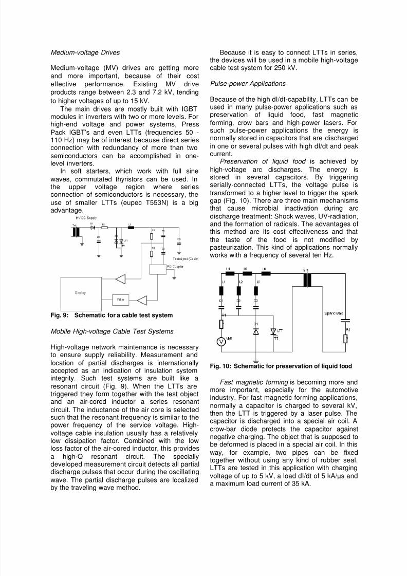
Preservation of liquid food is achieved by
high-voltage arc discharges. The energy isstored in several capacitors. By triggeringserially-connected LTTs, the voltage pulse is
transformed to a higher level to trigger the spark
gap (Fig. 10). There are three main mechanismsthat cause microbial inactivation during arc
discharge treatment: Shock waves, UV-radiation,and the formation of radicals. The advantages ofthis method are its cost effectiveness and that
the taste of the food is not modified bypasteurization. This kind of applications normallyworks with a frequency of several ten Hz.
Fig. 10: Schematic for preservation of liquid food
Fast magnetic forming is becoming more andmore important, especially for the automotiveindustry. For fast magnetic forming applications,
normally a capacitor is charged to several kV,then the LTT is triggered by a laser pulse. Thecapacitor is discharged into a special air coil. A
crow-bar diode protects the capacitor againstnegative charging. The object that is supposed tobe deformed is placed in a special air coil. In this
way, for example, two pipes can be fixedtogether without using any kind of rubber seal.LTTs are tested in this application with charging
voltage of up to 5 kV, a load dI/dt of 5 kA/µs anda maximum load current of 35 kA.

8/7/2019 HIGH-VOLTAGE THYRISTORS
http://slidepdf.com/reader/full/high-voltage-thyristors 6/6
LTTs are used in crow bar applications toprotect expensive and sensitive componentssuch as klystrons or high-power capacitor banks.
The LTTs are switched directly in parallel to thepart that should be protected (Fig. 11). In case ofovervoltage or high dV/dt in the system, the
internal protection function triggers the LTTs andthe current commutates to the thyristors. In caseof any other failures or irregular functions, the
LTTs are triggered by the laser pulse and theexpensive parts are protected. LTTs are tested inthis application with a charging voltage of 65 kV
and a dI/dt of about 5 kA/µs.
Fig. 11: Simplified schematic for a crow bar circuit
Fig. 12: Simplified schematic for laser application
High-power lasers are used in lithographyprocesses to produce processors and TFT-displays. First, a capacitor bank is charged to
several kilovolts (Fig. 12). Then, the LTTs aretriggered and the current flows through a coil toproduce a well-defined current pulse. This
current pulse is compressed by two or morepulse-compression circuits. After thiscompression, the current pulse triggers the laser.
These laser applications normally work at afrequency of several 100 Hz. LTTs are tested inthis application with a charging voltage of 16 kV,
a load dI/dt of 2 kA/µs, a maximum load current
of 2 kA, and a frequency of 300 Hz.Ignitrons are used in several existing
applications. These devices will be replacedbecause of the pollution that can be caused bythe mercury in them. LTTs are a good solution
for most of these replacements.
Summary
In conclusion, we point out that light-triggered
thyristors combined with self-protection functions
can be employed with great advantage toimprove the reliability of such systems as HVDCtransmission lines and other high-voltage AC and
DC applications.
Acknowledgments
We thank B. Baur, C. Schneider, J. Dorn, H.P.Lips, and M. Ruff for many fruitful discussions,and R.A. Bommersbach for experimental
support.
References
[1] H.-J. Schulze, M. Ruff, B. Baur, F. Pfirsch, H.Kabza, U. Kellner: "Light Triggered 8 kV-Thyristors with a New Type of IntegratedBreakover Diode", Proc. 8th Int. Symp. on PowerSemiconductor Devices and IC's, Maui Hawaii
USA, pp.197-200, 1996.[2] M. Ruff, H.-J. Schulze, and U. Kellner, "Progress
in the development of an 8-kV light-triggeredthyristor with integrated protection functions",IEEE (ED), vol. 46, no. 8, pp. 1768-1774, 1999.
[3] F.-J. Niedernostheide, H.-J. Schulze, and U.Kellner-Werdehausen, "Self-protection functionsin direct light-triggered high-power thyristors",Microelectronics Journal, vol. 32, no. 5-6, pp.457-462, 2001.
[4] F.-J. Niedernostheide, H.-J. Schulze, U. Kellner-Werdehausen, “Self-Protected High-PowerThyristors”, Proc. PCIM’2001, Power Conversion,Nuremberg, Germany, pp. 51-56, 2001.
[5] H.-J. Schulze, F.-J. Niedernostheide, U. Kellner-Werdehausen, “Thyristor with Integrated ForwardRecovery Protection Function”, Proc. of 2001 Int.Symp. on Power Semiconductor Devices andIC's, Osaka, Japan, pp. 199-202, 2001.
[6] H.-J. Schulze, F.-J. Niedernostheide, M. Schmitt,U. Kellner-Werdehausen, G. Wachutka,"Influence of Irradiation-Induced Defects on theElectrical Performance of Power Devices", in:High-Purity Silicon VII, ECS-PV, in print (2003).
[7] O.L. Harding, P.D. Taylor, and P.J. Frith, "Recentadvances in high voltage thyristor design", FourthInternational Conference on AC and DC PowerTransmission, London, pp. 315-319, 1985.
[8] R.W. Aliwell and D.E. Cress, "Development of aself-protected light triggered thyristor", IEEColloquium Devices, Drives, Circuits, andProtection, London, pp. 7/1-3, 1994.
[9] M.S. Towers and P. Mawby, "Self protected lighttriggered thyristors", IEE Colloquium Recent Ad-vances in Power Devices, London, p. 8/1-10,1999.
[10] H.P.Lips, J.Matern, R.Neubert, L.Popp, M. Uder,"Light Triggered Thyristor Valve For HVDCApplication", Proc. of 7th European Conferenceon Power Electronics and Applications, Volume1, pp. 1.287-1.292, Trondheim, Norway, 1997.


![High-Voltage Fully Isolated 2 Package, Surface-Mount, High … · Crowbar is a fault energy-diverting element [1] [2] built with series connected thyristors, connected at the output](https://img.pdfslide.us/doc/110x75/5c5e4dd809d3f28e758befc7/high-voltage-fully-isolated-2-package-surface-mount-high-crowbar-is-a-fault.jpg)