Embed Size (px)
Citation preview

High Throughput Data Center Topology Design
Ankit Singla, P. Brighten Godfrey, Alexandra Kolla


“How long must we wait until our pigeon system
rivals those of the Continental Powers?”
- The Nineteenth Century, 1899

The need for throughput
March 2011
May 2012[Facebook, via Wired]

Many topology options …
How do we design throughput optimal network topologies?

How do we design throughput optimal network
topologies?

How close can we get to optimal network capacity?
1

How close can we get to optimal network capacity?
1
How do we handle heterogeneity?2

Jellyfish: Networking Data Centers Randomly
[NSDI 2012: Singla, Hong, Popa, Godfrey]

[NSDI 2012: Singla, Hong, Popa, Godfrey]
Jellyfish: Networking Data Centers Randomly

[NSDI 2012: Singla, Hong, Popa, Godfrey]
• High capacity • Beat fat-trees by 25%+
Jellyfish: Networking Data Centers Randomly

[NSDI 2012: Singla, Hong, Popa, Godfrey]
• High capacity • Beat fat-trees by 25%+
• Easier to expand • 60% cheaper expansion
Jellyfish: Networking Data Centers Randomly

[NSDI 2012: Singla, Hong, Popa, Godfrey]
• High capacity • Beat fat-trees by 25%+
• Easier to expand • 60% cheaper expansion
• Routing and cabling are solvable problems
Jellyfish: Networking Data Centers Randomly

How close can we get to optimal network capacity?
1

How close can we get to optimal network capacity?
1
How do we handle heterogeneity?2

How do we measure throughput?

How do we measure throughput?
Maximize the minimum flow

How do we measure throughput?
Maximize the minimum flow
under random permutation traffic

How do we measure throughput?
Maximize the minimum flow
under random permutation traffic

How do we measure throughput?

How do we measure throughput?
• Bisection bandwidth ≠ throughput

How do we measure throughput?
• Bisection bandwidth ≠ throughput
• Near-worst case traffic patterns

How close can we get to optimal network capacity?

A simple upper bound
A simple upper bound
# flows

A simple upper bound
capacity used per flow# flows •

A simple upper bound
capacity used per flow# flows
≤ total capacity
•

A simple upper bound
capacity used per flow# flows
≤ total capacity
•

A simple upper bound
# flows
≤ total capacity
• throughput per flow • mean path length

A simple upper bound
total capacity
# flows • mean path length≤throughput per flow

A simple upper bound
∑links capacity(link)
# flows • mean path length≤throughput per flow

A simple upper bound
∑links capacity(link)
# flows • mean path length≤throughput per flow
Lower bound this!

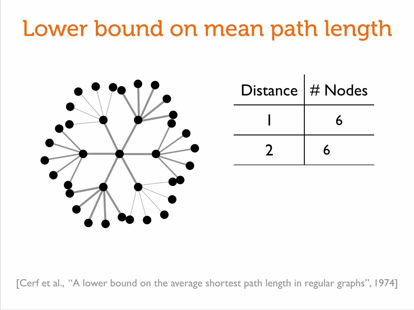
Lower bound on mean path length

Lower bound on mean path length

Lower bound on mean path length
[Cerf et al., “A lower bound on the average shortest path length in regular graphs”, 1974]

Lower bound on mean path length
Distance # Nodes
[Cerf et al., “A lower bound on the average shortest path length in regular graphs”, 1974]

Lower bound on mean path length
Distance # Nodes
1 6
[Cerf et al., “A lower bound on the average shortest path length in regular graphs”, 1974]
Lower bound on mean path length
Distance # Nodes
1 6
2 6
[Cerf et al., “A lower bound on the average shortest path length in regular graphs”, 1974]

Lower bound on mean path length
Distance # Nodes
1 6
2 6
(Ugliness omitted)
[Cerf et al., “A lower bound on the average shortest path length in regular graphs”, 1974]

Lower bound on mean path length
Distance # Nodes
1 6
2 6
(Ugliness omitted)
[Cerf et al., “A lower bound on the average shortest path length in regular graphs”, 1974]

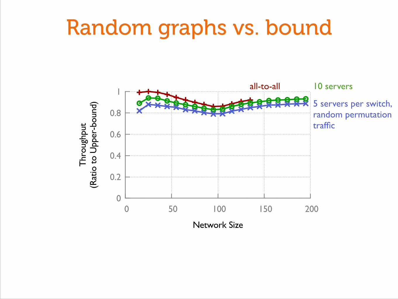
Random graphs vs. bound
0
0.2
0.4
0.6
0.8
1
0 50 100 150 200
Thr
ough
put
(Rat
io t
o U
pper
-bou
nd)
Network Size

Random graphs vs. bound
0
0.2
0.4
0.6
0.8
1
0 50 100 150 200
Thr
ough
put
(Rat
io t
o U
pper
-bou
nd)
Network Size
5 servers per switch, random permutation traffic
Random graphs vs. bound
0
0.2
0.4
0.6
0.8
1
0 50 100 150 200
Thr
ough
put
(Rat
io t
o U
pper
-bou
nd)
Network Size
10 servers
5 servers per switch, random permutation traffic
all-to-all

Random graphs vs. bound
0
0.2
0.4
0.6
0.8
1
0 50 100 150 200
Thr
ough
put
(Rat
io t
o U
pper
-bou
nd)
Network Size
10 servers
5 servers per switch, random permutation traffic
all-to-all
Random graphs within a few percent of optimal!

Random graphs vs. bound
0
0.2
0.4
0.6
0.8
1
0 50 100 150 200
Thr
ough
put
(Rat
io t
o U
pper
-bou
nd)
Network Size
10 servers
5 servers per switch, random permutation traffic
all-to-all
Random graphs within a few percent of optimal!
Random graphs exceed throughput of other topologies

How close can we get to optimal network capacity?
Very close!!

How do we handle heterogeneity?
Image credit: Legolizer (www.drububu.com)
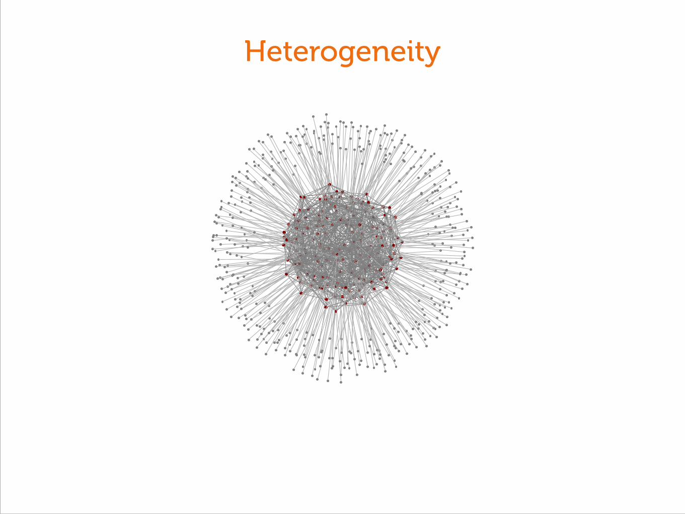
Heterogeneity

Heterogeneity


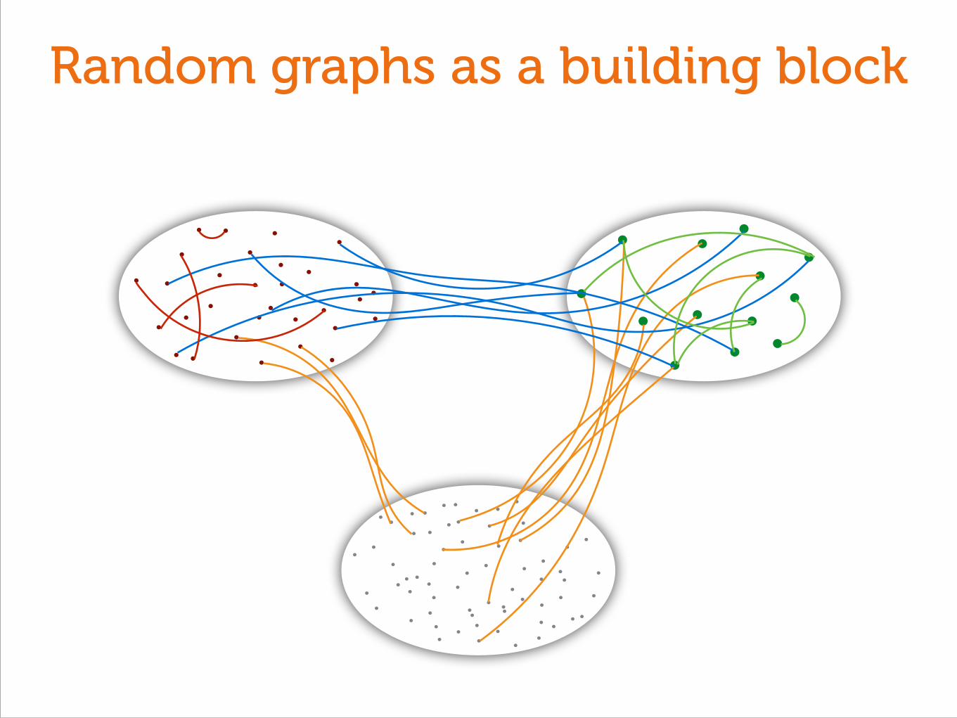
Random graphs as a building block

Random graphs as a building block
Low-degree switches
High-degree switches
Servers

? ?
1 How should we distribute servers?
Random graphs as a building block
Low-degree switches
High-degree switches
Servers

? ?
1 How should we distribute servers?
?
2 How should we interconnect switches?
Random graphs as a building block
Low-degree switches
High-degree switches
Servers

? ?
1 How should we distribute servers?
?
2 How should we interconnect switches?
Random graphs as a building block
Low-degree switches
High-degree switches
Servers
Distributing servers

Distributing servers

Distributing servers

Distributing servers

Distributing servers
0
0.2
0.4
0.6
0.8
1
0.4 0.6 0.8 1 1.2 1.4 1.6 1.8 2
Nor
mal
ized
Thr
ough
put
Number of Servers at Large Switches(Ratio to Expected Under Random Distribution)

Distributing servers
0
0.2
0.4
0.6
0.8
1
0.4 0.6 0.8 1 1.2 1.4 1.6 1.8 2
Nor
mal
ized
Thr
ough
put
Number of Servers at Large Switches(Ratio to Expected Under Random Distribution)
Distributing servers
0
0.2
0.4
0.6
0.8
1
0.4 0.6 0.8 1 1.2 1.4 1.6 1.8 2
Nor
mal
ized
Thr
ough
put
Number of Servers at Large Switches(Ratio to Expected Under Random Distribution)
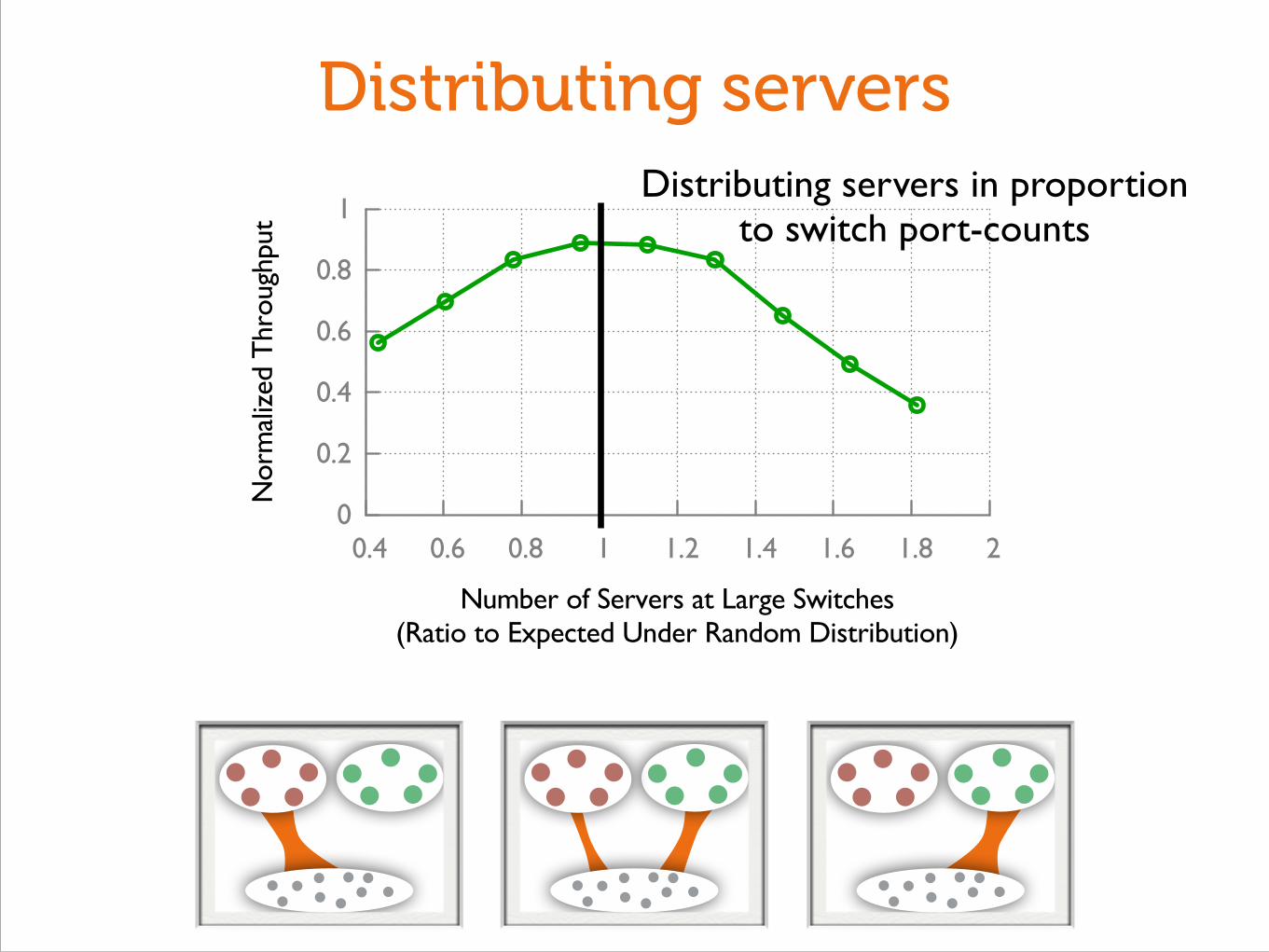
Distributing servers in proportion to switch port-counts

Distributing servers
0
0.2
0.4
0.6
0.8
1
0.4 0.6 0.8 1 1.2 1.4 1.6 1.8 2
Nor
mal
ized
Thr
ough
put
Number of Servers at Large Switches(Ratio to Expected Under Random Distribution)
Distributing servers in proportion to switch port-counts

Distributing servers
0
0.2
0.4
0.6
0.8
1
0.4 0.6 0.8 1 1.2 1.4 1.6 1.8 2
Nor
mal
ized
Thr
ough
put
Number of Servers at Large Switches(Ratio to Expected Under Random Distribution)
Distributing servers in proportion to switch port-counts
Networks aren’t built like this today!

Random graphs as a building block
Low-degree switches
High-degree switches
Servers
?
?
?
1 How should we distribute servers?
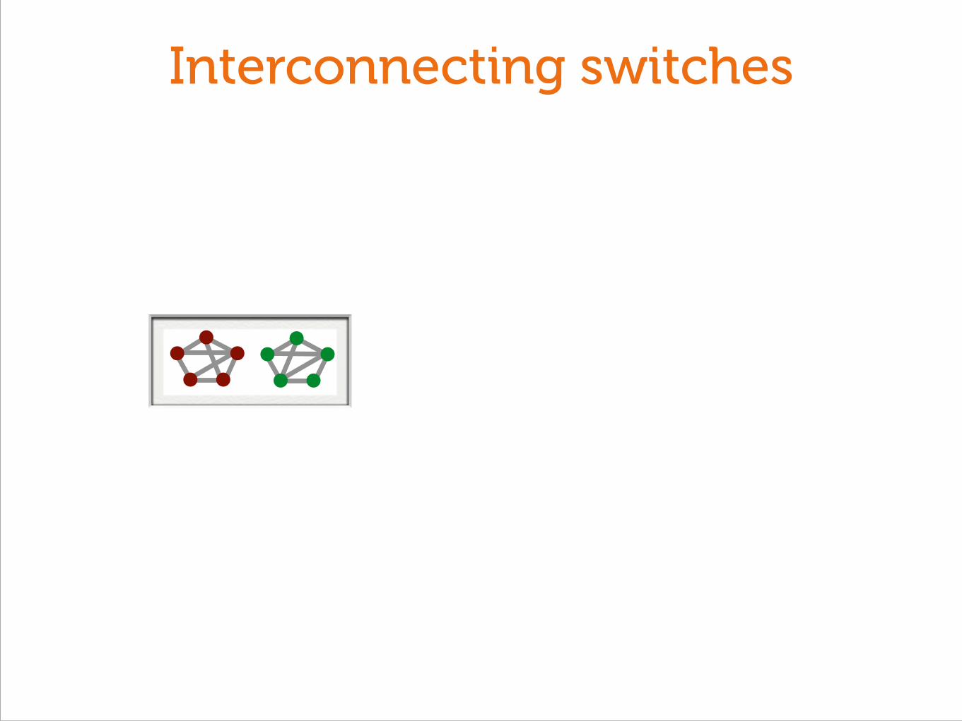
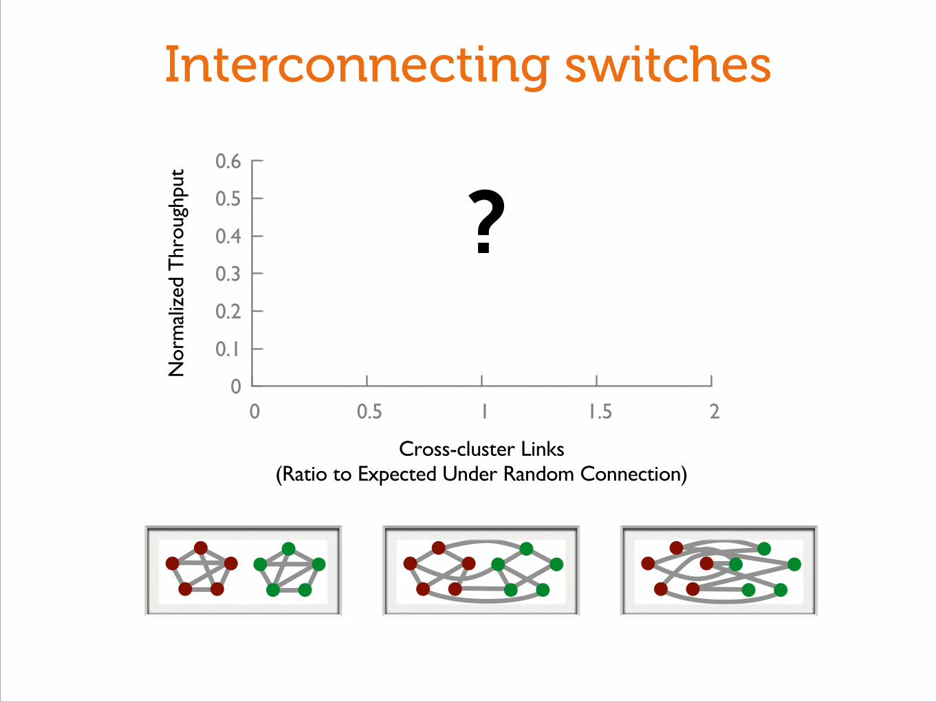
2 How should we interconnect switches?

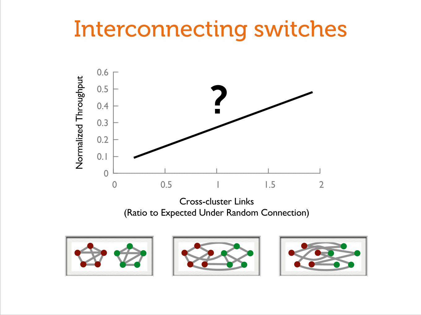
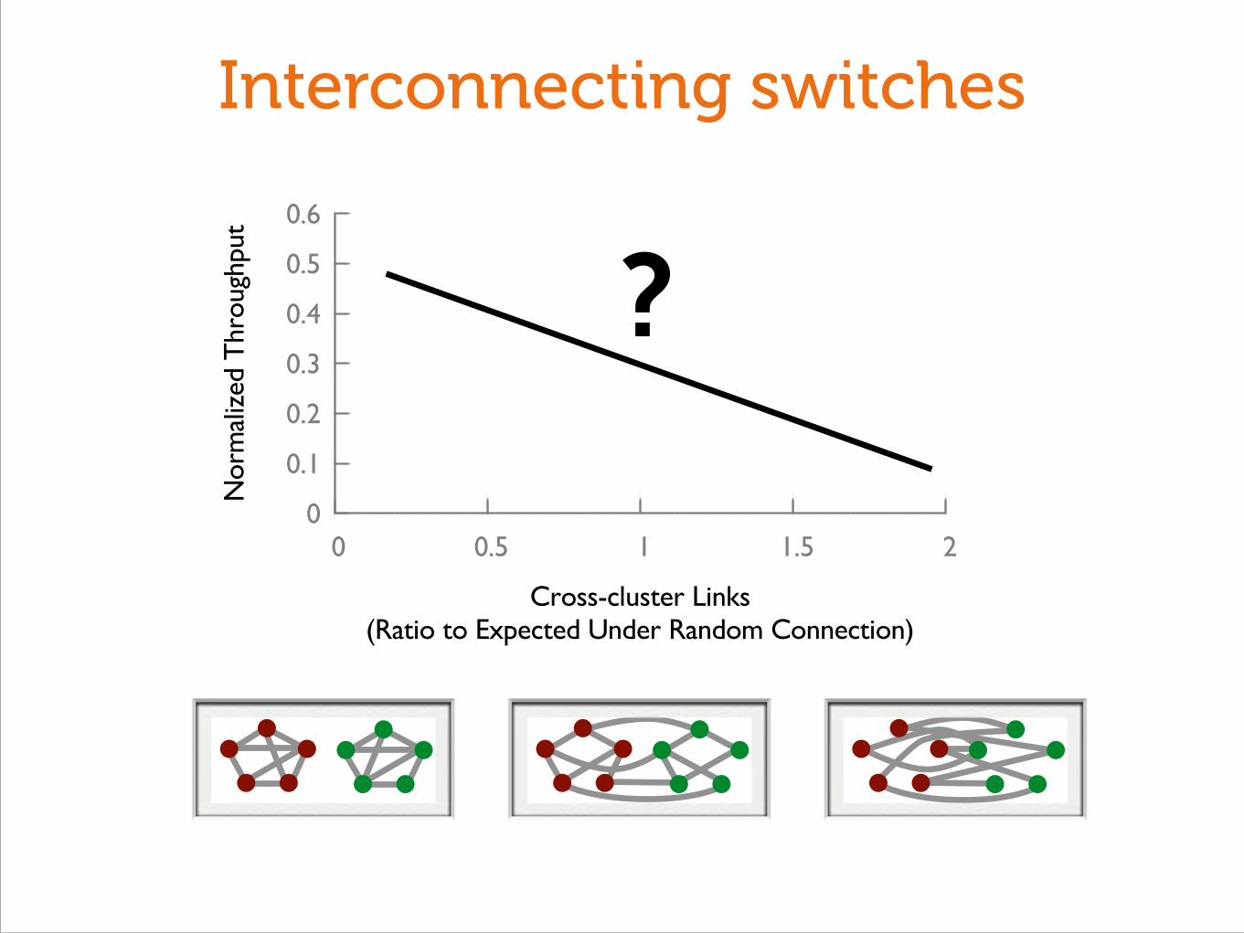
Interconnecting switches
Interconnecting switches

Interconnecting switches

Interconnecting switches

0
0.1
0.2
0.3
0.4
0.5
0.6
0 0.5 1 1.5 2
Nor
mal
ized
Thr
ough
put
Cross-cluster Links(Ratio to Expected Under Random Connection)
Interconnecting switches
0
0.1
0.2
0.3
0.4
0.5
0.6
0 0.5 1 1.5 2
Nor
mal
ized
Thr
ough
put
Cross-cluster Links(Ratio to Expected Under Random Connection)
Interconnecting switches
?

0
0.1
0.2
0.3
0.4
0.5
0.6
0 0.5 1 1.5 2
Nor
mal
ized
Thr
ough
put
Cross-cluster Links(Ratio to Expected Under Random Connection)
Interconnecting switches
?
0
0.1
0.2
0.3
0.4
0.5
0.6
0 0.5 1 1.5 2
Nor
mal
ized
Thr
ough
put
Cross-cluster Links(Ratio to Expected Under Random Connection)
Interconnecting switches
?
0
0.1
0.2
0.3
0.4
0.5
0.6
0 0.5 1 1.5 2
Nor
mal
ized
Thr
ough
put
Cross-cluster Links(Ratio to Expected Under Random Connection)
Interconnecting switches
?

0
0.1
0.2
0.3
0.4
0.5
0.6
0 0.5 1 1.5 2
Nor
mal
ized
Thr
ough
put
Cross-cluster Links(Ratio to Expected Under Random Connection)
Interconnecting switches
?

Interconnecting switches
0
0.1
0.2
0.3
0.4
0.5
0.6
0 0.5 1 1.5 2
Nor
mal
ized
Thr
ough
put
Cross-cluster Links(Ratio to Expected Under Random Connection)

0
0.1
0.2
0.3
0.4
0.5
0.6
0 0.5 1 1.5 2
Nor
mal
ized
Thr
ough
put
Cross-cluster Links(Ratio to Expected Under Random Connection)
Interconnecting switches

0
0.1
0.2
0.3
0.4
0.5
0.6
0 0.5 1 1.5 2
Nor
mal
ized
Thr
ough
put
Cross-cluster Links(Ratio to Expected Under Random Connection)
Interconnecting switchesVanilla random interconnect

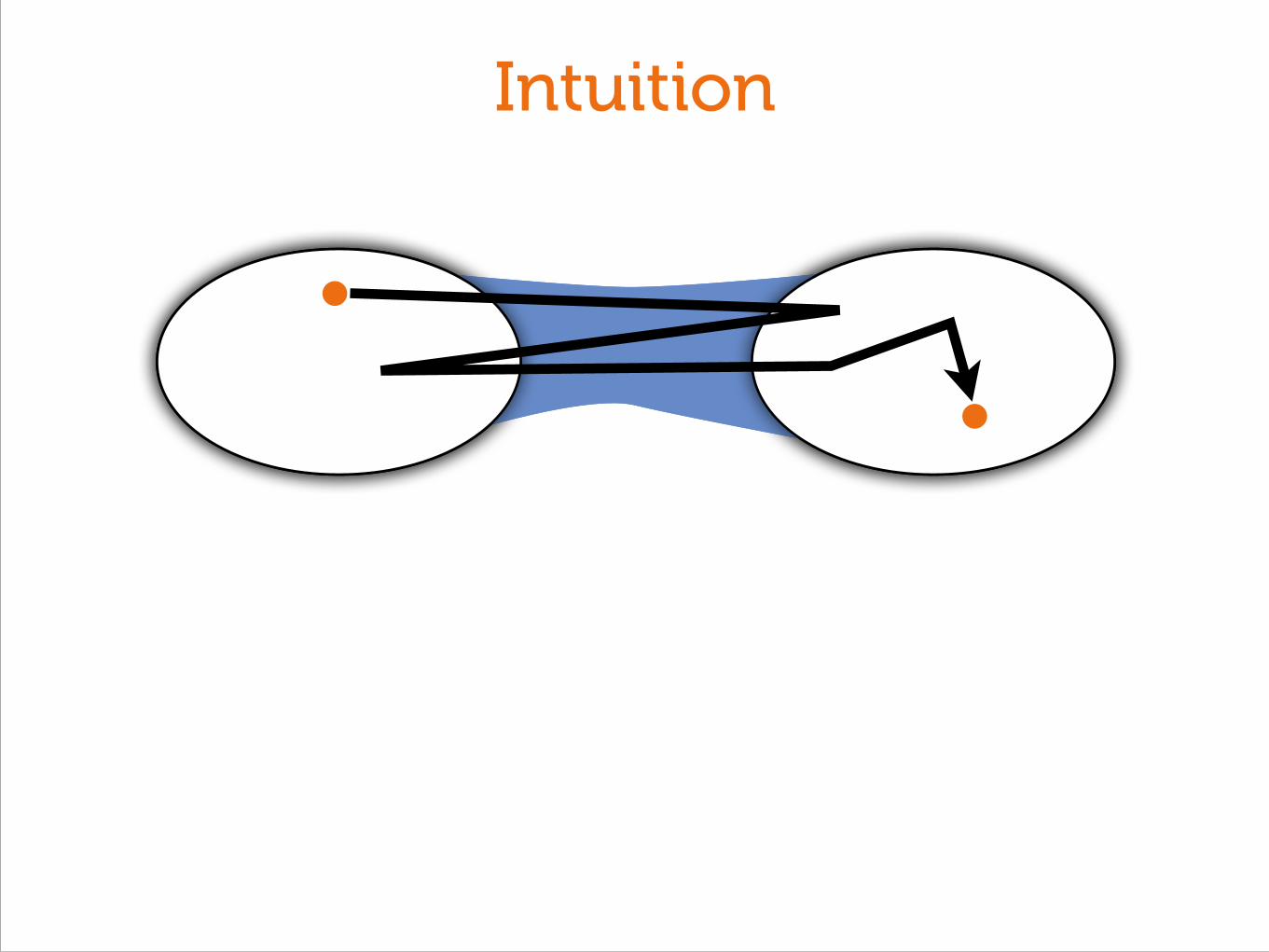
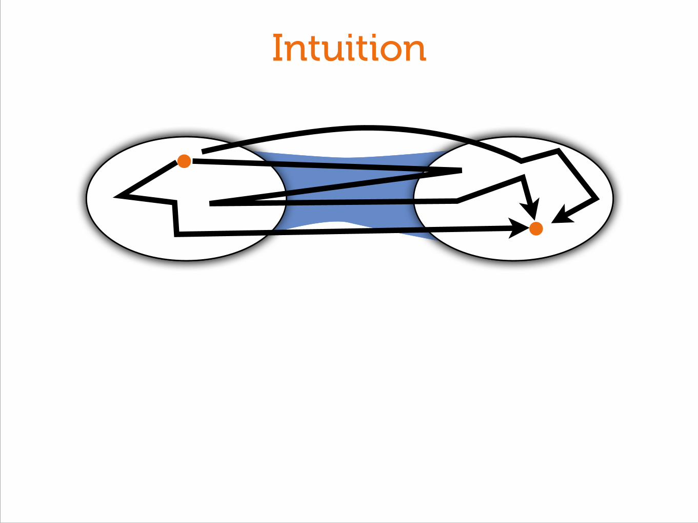
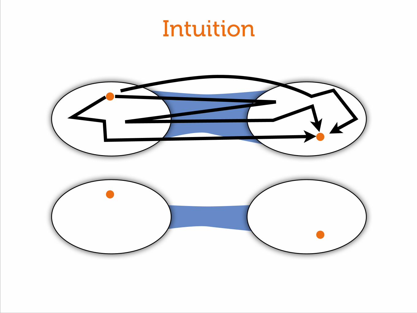
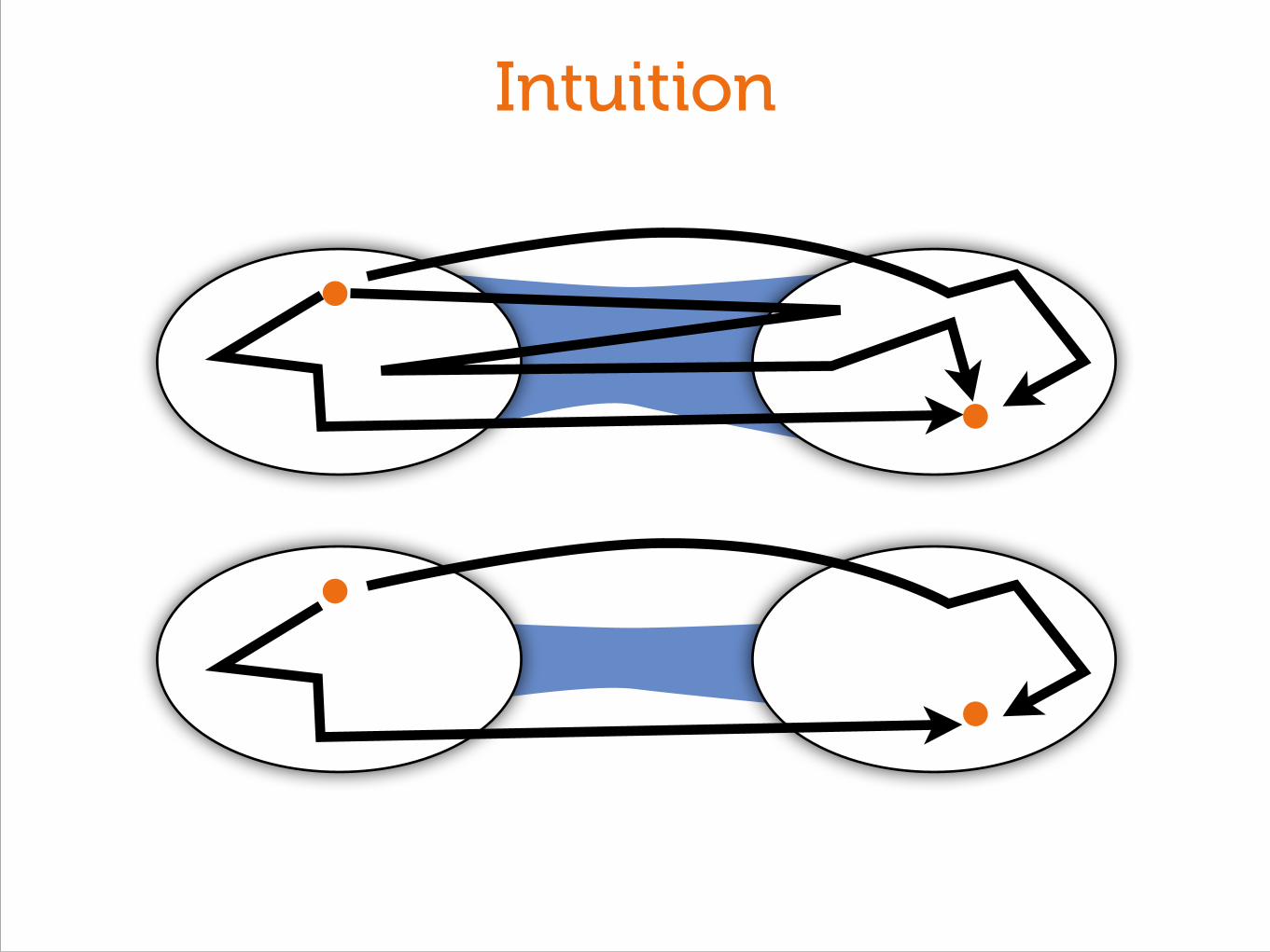
Intuition
Intuition

Intuition
Intuition

Intuition
Intuition

Intuition
Intuition

Intuition
Still need one crossing!

Intuition
Still need one crossing!
⇥
✓1
APL
◆

Intuition
Still need one crossing!
⇥
✓1
APL
◆Throughput should drop when less than
of total capacity crosses the cut!
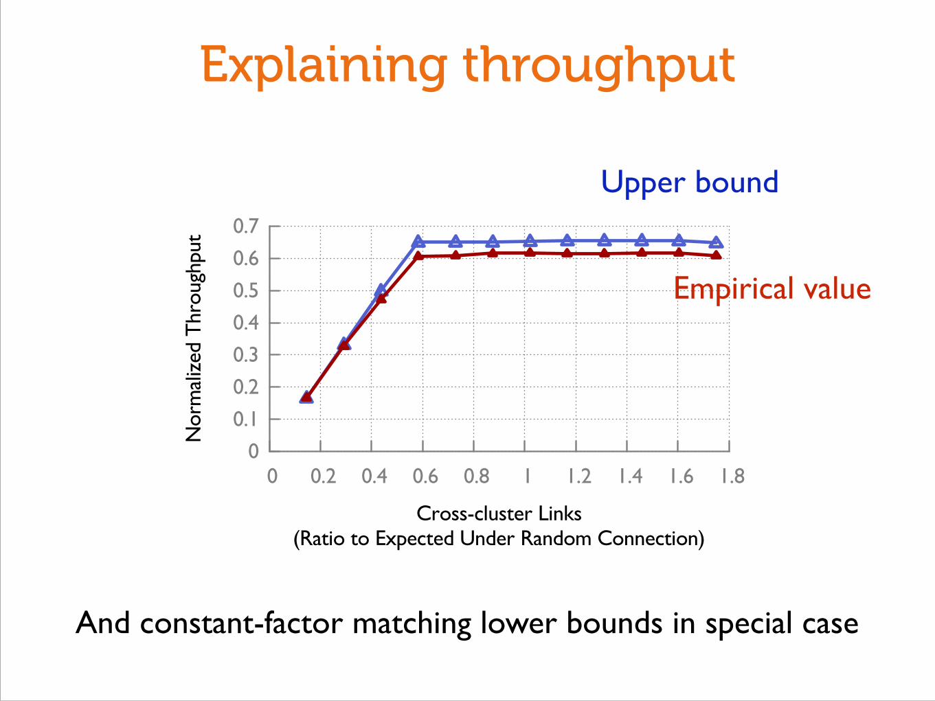
Explaining throughput
Upper bound
And constant-factor matching lower bounds in special case
0
0.1
0.2
0.3
0.4
0.5
0.6
0.7
0 0.2 0.4 0.6 0.8 1 1.2 1.4 1.6 1.8
Nor
mal
ized
Thr
ough
put
Cross-cluster Links(Ratio to Expected Under Random Connection)
Empirical value

Two regimes of throughput
0
0.1
0.2
0.3
0.4
0.5
0.6
0.7
0 0.2 0.4 0.6 0.8 1 1.2 1.4 1.6 1.8
Nor
mal
ized
Thr
ough
put
Cross-cluster Links(Ratio to Expected Under Random Connection)

Two regimes of throughput
0
0.1
0.2
0.3
0.4
0.5
0.6
0.7
0 0.2 0.4 0.6 0.8 1 1.2 1.4 1.6 1.8
Nor
mal
ized
Thr
ough
put
Cross-cluster Links(Ratio to Expected Under Random Connection)
sparsest cut

Two regimes of throughput
0
0.1
0.2
0.3
0.4
0.5
0.6
0.7
0 0.2 0.4 0.6 0.8 1 1.2 1.4 1.6 1.8
Nor
mal
ized
Thr
ough
put
Cross-cluster Links(Ratio to Expected Under Random Connection)
sparsest cut“plateau”:
(total cap) / APL

Implications
A wide range of connectivity options

Implications
A wide range of connectivity options

Implications
A wide range of connectivity options
Bisection bandwidth ≠ throughput

Implications
A wide range of connectivity options
Bisection bandwidth ≠ throughput
Greater freedom in cabling

Quick recap!

0 How close can we get to optimal network capacity?
0
0.2
0.4
0.6
0.8
1
0 50 100 150 200
Thr
ough
put
(Rat
io t
o U
pper
-bou
nd)
Network Size

0 How close can we get to optimal network capacity?
0
0.2
0.4
0.6
0.8
1
0 50 100 150 200
Thr
ough
put
(Rat
io t
o U
pper
-bou
nd)
Network Size
1 How should we distribute servers?
0
0.2
0.4
0.6
0.8
1
0.4 0.6 0.8 1 1.2 1.4 1.6 1.8 2
Nor
mal
ized
Thr
ough
put
Number of Servers at Large Switches(Ratio to Expected Under Random Distribution)
2 How should we interconnect switches?
0
0.1
0.2
0.3
0.4
0.5
0.6
0 0.5 1 1.5 2
Nor
mal
ized
Thr
ough
put
Cross-cluster Links(Ratio to Expected Under Random Connection)

Improving a REAL heterogeneous topology

The VL2 topology
. . .
. . .
!"#
$%&
. . .
. . . .
'(()
DA/2 x 10G
DA/2 x 10G
DI x10G
2 x10G DADI/4 x ToR Switches
DI x Aggregate Switches
20(DADI/4) x Servers
InternetLink-state networkcarrying only LAs
(e.g., 10/8) DA/2 x Intermediate Switches
Fungible pool ofservers owning AAs
(e.g., 20/8)
Figure : An exampleClos network betweenAggregation and In-termediate switches provides a richly-connected backbone well-suited for VLB. The network is built with two separate addressfamilies— topologically significant LocatorAddresses (LAs) andflat Application Addresses (AAs).
dundancy to improve reliability at higher layers of the hierarchicaltree. Despite these techniques, we find that in . of failures allredundant components in a network device group became unavail-able (e.g., the pair of switches that comprise each node in the con-ventional network (Figure ) or both the uplinks from a switch). Inone incident, the failure of a core switch (due to a faulty supervi-sor card) affected ten million users for about four hours. We foundthe main causes of these downtimes are networkmisconfigurations,firmware bugs, and faulty components (e.g., ports). With no obvi-ous way to eliminate all failures from the top of the hierarchy, VL’sapproach is to broaden the topmost levels of the network so that theimpact of failures is muted and performance degrades gracefully,moving from : redundancy to n:m redundancy.
4. VIRTUAL LAYER TWO NETWORKINGBefore detailing our solution, we brieflydiscuss our design prin-
ciples and preview how they will be used in the VL design.Randomizing to Cope with Volatility: VL copes with
the high divergence and unpredictability of data-center trafficmatrices by using Valiant Load Balancing to do destination-independent (e.g., random) traffic spreading across multiple inter-mediate nodes. We introduce our network topology suited for VLBin §., and the corresponding flow spreading mechanism in §..
VLB, in theory, ensures a non-interfering packet switched net-work [], the counterpart of a non-blocking circuit switched net-work, as long as (a) traffic spreading ratios are uniform, and (b) theoffered traffic patterns do not violate edge constraints (i.e., line cardspeeds). To meet the latter condition, we rely on TCP’s end-to-endcongestion control mechanism. While our mechanisms to realizeVLB do not perfectly meet either of these conditions, we show in§. that our scheme’s performance is close to the optimum.
Building on proven networking technology: VL is based onIP routing and forwarding technologies that are already availablein commodity switches: link-state routing, equal-cost multi-path(ECMP) forwarding, IP anycasting, and IP multicasting. VL usesa link-state routing protocol to maintain the switch-level topology,but not to disseminate endhosts’ information.This strategyprotectsswitches from needing to learn voluminous, frequently-changinghost information. Furthermore, the routing design uses ECMP for-warding along with anycast addresses to enable VLB with minimalcontrol plane messaging or churn.
Separating names from locators: The data center networkmust support agility, whichmeans, in particular, support for hostingany service on any server, for rapid growing and shrinking of serverpools, and for rapid virtual machine migration. In turn, this callsfor separating names from locations. VL’s addressing scheme sep-arates server names, termed application-specific addresses (AAs),from their locations, termed location-specific addresses (LAs). VLuses a scalable, reliable directory system to maintain the mappingsbetween names and locators. A shim layer running in the networkstack on every server, called the VL agent, invokes the directorysystem’s resolution service. We evaluate the performance of the di-rectory system in §..
Embracing End Systems: The rich and homogeneous pro-grammability available at data-center hosts provides a mechanismto rapidly realize new functionality. For example, the VL agent en-ables fine-grained path control by adjusting the randomization usedin VLB. The agent also replaces Ethernet’s ARP functionality withqueries to the VL directory system. The directory system itself isalso realized on servers, rather than switches, and thus offers flexi-bility, such as fine-grained, context-aware server access control anddynamic service re-provisioning.
We next describe each aspect of the VL system and how theywork together to implement a virtual layer- network.These aspectsinclude the network topology, the addressing and routing design,and the directory that manages name-locator mappings.
4.1 Scale-out TopologiesAs described in §., conventional hierarchical data-center
topologies have poor bisection bandwidth and are also suscepti-ble to major disruptions due to device failures at the highest levels.Rather than scale up individual network devices with more capac-ity and features, we scale out the devices — build a broad networkoffering huge aggregate capacity using a large number of simple, in-expensive devices, as shown in Figure . This is an example of afolded Clos network [] where the links between the Intermedi-ate switches and the Aggregation switches form a complete bipar-tite graph. As in the conventional topology, ToRs connect to twoAggregation switches, but the large number of paths between ev-ery two Aggregation switches means that if there are n Intermedi-ate switches, the failure of any one of them reduces the bisectionbandwidth by only 1/n–a desirable graceful degradation of band-width that we evaluate in §.. Further, it is easy and less expen-sive to build a Clos network for which there is no over-subscription(further discussion on cost is in §). For example, in Figure , weuse DA-port Aggregation and DI -port Intermediate switches, andconnect these switches such that the capacity between each layer isDIDA/2 times the link capacity.
The Clos topology is exceptionally well suited for VLB in that byindirectly forwarding traffic through an Intermediate switch at thetop tier or “spine” of the network, the network can provide band-width guarantees for any traffic matrices subject to the hose model.Meanwhile, routing is extremely simple and resilient on this topol-ogy — take a random path up to a random intermediate switch anda random path down to a destination ToR switch.
VL leverages the fact that at every generation of technol-ogy, switch-to-switch links are typically faster than server-to-switchlinks, and trends suggest that this gap will remain. Our current de-sign uses G server links and G switch links, and the next designpoint will probably be G server links with G switch links. Byleveraging this gap, we reduce the number of cables required to im-plement the Clos (as compared with a fat-tree []), and we simplifythe task of spreading load over the links (§.).
55
[Greenburg, Hamilton, Jain, Kandula, Kim, Lahiri, Maltz, Patel, Sengupta, SIGCOMM’09]

The VL2 topology
. . .
. . .
!"#
$%&
. . .
. . . .
'(()
DA/2 x 10G
DA/2 x 10G
DI x10G
2 x10G DADI/4 x ToR Switches
DI x Aggregate Switches
20(DADI/4) x Servers
InternetLink-state networkcarrying only LAs
(e.g., 10/8) DA/2 x Intermediate Switches
Fungible pool ofservers owning AAs
(e.g., 20/8)
Figure : An exampleClos network betweenAggregation and In-termediate switches provides a richly-connected backbone well-suited for VLB. The network is built with two separate addressfamilies— topologically significant LocatorAddresses (LAs) andflat Application Addresses (AAs).
dundancy to improve reliability at higher layers of the hierarchicaltree. Despite these techniques, we find that in . of failures allredundant components in a network device group became unavail-able (e.g., the pair of switches that comprise each node in the con-ventional network (Figure ) or both the uplinks from a switch). Inone incident, the failure of a core switch (due to a faulty supervi-sor card) affected ten million users for about four hours. We foundthe main causes of these downtimes are networkmisconfigurations,firmware bugs, and faulty components (e.g., ports). With no obvi-ous way to eliminate all failures from the top of the hierarchy, VL’sapproach is to broaden the topmost levels of the network so that theimpact of failures is muted and performance degrades gracefully,moving from : redundancy to n:m redundancy.
4. VIRTUAL LAYER TWO NETWORKINGBefore detailing our solution, we brieflydiscuss our design prin-
ciples and preview how they will be used in the VL design.Randomizing to Cope with Volatility: VL copes with
the high divergence and unpredictability of data-center trafficmatrices by using Valiant Load Balancing to do destination-independent (e.g., random) traffic spreading across multiple inter-mediate nodes. We introduce our network topology suited for VLBin §., and the corresponding flow spreading mechanism in §..
VLB, in theory, ensures a non-interfering packet switched net-work [], the counterpart of a non-blocking circuit switched net-work, as long as (a) traffic spreading ratios are uniform, and (b) theoffered traffic patterns do not violate edge constraints (i.e., line cardspeeds). To meet the latter condition, we rely on TCP’s end-to-endcongestion control mechanism. While our mechanisms to realizeVLB do not perfectly meet either of these conditions, we show in§. that our scheme’s performance is close to the optimum.
Building on proven networking technology: VL is based onIP routing and forwarding technologies that are already availablein commodity switches: link-state routing, equal-cost multi-path(ECMP) forwarding, IP anycasting, and IP multicasting. VL usesa link-state routing protocol to maintain the switch-level topology,but not to disseminate endhosts’ information.This strategyprotectsswitches from needing to learn voluminous, frequently-changinghost information. Furthermore, the routing design uses ECMP for-warding along with anycast addresses to enable VLB with minimalcontrol plane messaging or churn.
Separating names from locators: The data center networkmust support agility, whichmeans, in particular, support for hostingany service on any server, for rapid growing and shrinking of serverpools, and for rapid virtual machine migration. In turn, this callsfor separating names from locations. VL’s addressing scheme sep-arates server names, termed application-specific addresses (AAs),from their locations, termed location-specific addresses (LAs). VLuses a scalable, reliable directory system to maintain the mappingsbetween names and locators. A shim layer running in the networkstack on every server, called the VL agent, invokes the directorysystem’s resolution service. We evaluate the performance of the di-rectory system in §..
Embracing End Systems: The rich and homogeneous pro-grammability available at data-center hosts provides a mechanismto rapidly realize new functionality. For example, the VL agent en-ables fine-grained path control by adjusting the randomization usedin VLB. The agent also replaces Ethernet’s ARP functionality withqueries to the VL directory system. The directory system itself isalso realized on servers, rather than switches, and thus offers flexi-bility, such as fine-grained, context-aware server access control anddynamic service re-provisioning.
We next describe each aspect of the VL system and how theywork together to implement a virtual layer- network.These aspectsinclude the network topology, the addressing and routing design,and the directory that manages name-locator mappings.
4.1 Scale-out TopologiesAs described in §., conventional hierarchical data-center
topologies have poor bisection bandwidth and are also suscepti-ble to major disruptions due to device failures at the highest levels.Rather than scale up individual network devices with more capac-ity and features, we scale out the devices — build a broad networkoffering huge aggregate capacity using a large number of simple, in-expensive devices, as shown in Figure . This is an example of afolded Clos network [] where the links between the Intermedi-ate switches and the Aggregation switches form a complete bipar-tite graph. As in the conventional topology, ToRs connect to twoAggregation switches, but the large number of paths between ev-ery two Aggregation switches means that if there are n Intermedi-ate switches, the failure of any one of them reduces the bisectionbandwidth by only 1/n–a desirable graceful degradation of band-width that we evaluate in §.. Further, it is easy and less expen-sive to build a Clos network for which there is no over-subscription(further discussion on cost is in §). For example, in Figure , weuse DA-port Aggregation and DI -port Intermediate switches, andconnect these switches such that the capacity between each layer isDIDA/2 times the link capacity.
The Clos topology is exceptionally well suited for VLB in that byindirectly forwarding traffic through an Intermediate switch at thetop tier or “spine” of the network, the network can provide band-width guarantees for any traffic matrices subject to the hose model.Meanwhile, routing is extremely simple and resilient on this topol-ogy — take a random path up to a random intermediate switch anda random path down to a destination ToR switch.
VL leverages the fact that at every generation of technol-ogy, switch-to-switch links are typically faster than server-to-switchlinks, and trends suggest that this gap will remain. Our current de-sign uses G server links and G switch links, and the next designpoint will probably be G server links with G switch links. Byleveraging this gap, we reduce the number of cables required to im-plement the Clos (as compared with a fat-tree []), and we simplifythe task of spreading load over the links (§.).
55
High-degree switches
Low-degree switches
ToRs ≈ Servers

Rewiring VL2
. . .
. . .
!"#
$%&
. . .
. . . .
'(()
DA/2 x 10G
DA/2 x 10G
DI x10G
2 x10G DADI/4 x ToR Switches
DI x Aggregate Switches
20(DADI/4) x Servers
InternetLink-state networkcarrying only LAs
(e.g., 10/8) DA/2 x Intermediate Switches
Fungible pool ofservers owning AAs
(e.g., 20/8)
Figure : An exampleClos network betweenAggregation and In-termediate switches provides a richly-connected backbone well-suited for VLB. The network is built with two separate addressfamilies— topologically significant LocatorAddresses (LAs) andflat Application Addresses (AAs).
dundancy to improve reliability at higher layers of the hierarchicaltree. Despite these techniques, we find that in . of failures allredundant components in a network device group became unavail-able (e.g., the pair of switches that comprise each node in the con-ventional network (Figure ) or both the uplinks from a switch). Inone incident, the failure of a core switch (due to a faulty supervi-sor card) affected ten million users for about four hours. We foundthe main causes of these downtimes are networkmisconfigurations,firmware bugs, and faulty components (e.g., ports). With no obvi-ous way to eliminate all failures from the top of the hierarchy, VL’sapproach is to broaden the topmost levels of the network so that theimpact of failures is muted and performance degrades gracefully,moving from : redundancy to n:m redundancy.
4. VIRTUAL LAYER TWO NETWORKINGBefore detailing our solution, we brieflydiscuss our design prin-
ciples and preview how they will be used in the VL design.Randomizing to Cope with Volatility: VL copes with
the high divergence and unpredictability of data-center trafficmatrices by using Valiant Load Balancing to do destination-independent (e.g., random) traffic spreading across multiple inter-mediate nodes. We introduce our network topology suited for VLBin §., and the corresponding flow spreading mechanism in §..
VLB, in theory, ensures a non-interfering packet switched net-work [], the counterpart of a non-blocking circuit switched net-work, as long as (a) traffic spreading ratios are uniform, and (b) theoffered traffic patterns do not violate edge constraints (i.e., line cardspeeds). To meet the latter condition, we rely on TCP’s end-to-endcongestion control mechanism. While our mechanisms to realizeVLB do not perfectly meet either of these conditions, we show in§. that our scheme’s performance is close to the optimum.
Building on proven networking technology: VL is based onIP routing and forwarding technologies that are already availablein commodity switches: link-state routing, equal-cost multi-path(ECMP) forwarding, IP anycasting, and IP multicasting. VL usesa link-state routing protocol to maintain the switch-level topology,but not to disseminate endhosts’ information.This strategyprotectsswitches from needing to learn voluminous, frequently-changinghost information. Furthermore, the routing design uses ECMP for-warding along with anycast addresses to enable VLB with minimalcontrol plane messaging or churn.
Separating names from locators: The data center networkmust support agility, whichmeans, in particular, support for hostingany service on any server, for rapid growing and shrinking of serverpools, and for rapid virtual machine migration. In turn, this callsfor separating names from locations. VL’s addressing scheme sep-arates server names, termed application-specific addresses (AAs),from their locations, termed location-specific addresses (LAs). VLuses a scalable, reliable directory system to maintain the mappingsbetween names and locators. A shim layer running in the networkstack on every server, called the VL agent, invokes the directorysystem’s resolution service. We evaluate the performance of the di-rectory system in §..
Embracing End Systems: The rich and homogeneous pro-grammability available at data-center hosts provides a mechanismto rapidly realize new functionality. For example, the VL agent en-ables fine-grained path control by adjusting the randomization usedin VLB. The agent also replaces Ethernet’s ARP functionality withqueries to the VL directory system. The directory system itself isalso realized on servers, rather than switches, and thus offers flexi-bility, such as fine-grained, context-aware server access control anddynamic service re-provisioning.
We next describe each aspect of the VL system and how theywork together to implement a virtual layer- network.These aspectsinclude the network topology, the addressing and routing design,and the directory that manages name-locator mappings.
4.1 Scale-out TopologiesAs described in §., conventional hierarchical data-center
topologies have poor bisection bandwidth and are also suscepti-ble to major disruptions due to device failures at the highest levels.Rather than scale up individual network devices with more capac-ity and features, we scale out the devices — build a broad networkoffering huge aggregate capacity using a large number of simple, in-expensive devices, as shown in Figure . This is an example of afolded Clos network [] where the links between the Intermedi-ate switches and the Aggregation switches form a complete bipar-tite graph. As in the conventional topology, ToRs connect to twoAggregation switches, but the large number of paths between ev-ery two Aggregation switches means that if there are n Intermedi-ate switches, the failure of any one of them reduces the bisectionbandwidth by only 1/n–a desirable graceful degradation of band-width that we evaluate in §.. Further, it is easy and less expen-sive to build a Clos network for which there is no over-subscription(further discussion on cost is in §). For example, in Figure , weuse DA-port Aggregation and DI -port Intermediate switches, andconnect these switches such that the capacity between each layer isDIDA/2 times the link capacity.
The Clos topology is exceptionally well suited for VLB in that byindirectly forwarding traffic through an Intermediate switch at thetop tier or “spine” of the network, the network can provide band-width guarantees for any traffic matrices subject to the hose model.Meanwhile, routing is extremely simple and resilient on this topol-ogy — take a random path up to a random intermediate switch anda random path down to a destination ToR switch.
VL leverages the fact that at every generation of technol-ogy, switch-to-switch links are typically faster than server-to-switchlinks, and trends suggest that this gap will remain. Our current de-sign uses G server links and G switch links, and the next designpoint will probably be G server links with G switch links. Byleveraging this gap, we reduce the number of cables required to im-plement the Clos (as compared with a fat-tree []), and we simplifythe task of spreading load over the links (§.).
55
Connect ToRs proportional to Intermediate/Agg degree

Rewiring VL2
. . .
. . .
!"#
$%&
. . .
. . . .
'(()
DA/2 x 10G
DA/2 x 10G
DI x10G
2 x10G DADI/4 x ToR Switches
DI x Aggregate Switches
20(DADI/4) x Servers
InternetLink-state networkcarrying only LAs
(e.g., 10/8) DA/2 x Intermediate Switches
Fungible pool ofservers owning AAs
(e.g., 20/8)
Figure : An exampleClos network betweenAggregation and In-termediate switches provides a richly-connected backbone well-suited for VLB. The network is built with two separate addressfamilies— topologically significant LocatorAddresses (LAs) andflat Application Addresses (AAs).
dundancy to improve reliability at higher layers of the hierarchicaltree. Despite these techniques, we find that in . of failures allredundant components in a network device group became unavail-able (e.g., the pair of switches that comprise each node in the con-ventional network (Figure ) or both the uplinks from a switch). Inone incident, the failure of a core switch (due to a faulty supervi-sor card) affected ten million users for about four hours. We foundthe main causes of these downtimes are networkmisconfigurations,firmware bugs, and faulty components (e.g., ports). With no obvi-ous way to eliminate all failures from the top of the hierarchy, VL’sapproach is to broaden the topmost levels of the network so that theimpact of failures is muted and performance degrades gracefully,moving from : redundancy to n:m redundancy.
4. VIRTUAL LAYER TWO NETWORKINGBefore detailing our solution, we brieflydiscuss our design prin-
ciples and preview how they will be used in the VL design.Randomizing to Cope with Volatility: VL copes with
the high divergence and unpredictability of data-center trafficmatrices by using Valiant Load Balancing to do destination-independent (e.g., random) traffic spreading across multiple inter-mediate nodes. We introduce our network topology suited for VLBin §., and the corresponding flow spreading mechanism in §..
VLB, in theory, ensures a non-interfering packet switched net-work [], the counterpart of a non-blocking circuit switched net-work, as long as (a) traffic spreading ratios are uniform, and (b) theoffered traffic patterns do not violate edge constraints (i.e., line cardspeeds). To meet the latter condition, we rely on TCP’s end-to-endcongestion control mechanism. While our mechanisms to realizeVLB do not perfectly meet either of these conditions, we show in§. that our scheme’s performance is close to the optimum.
Building on proven networking technology: VL is based onIP routing and forwarding technologies that are already availablein commodity switches: link-state routing, equal-cost multi-path(ECMP) forwarding, IP anycasting, and IP multicasting. VL usesa link-state routing protocol to maintain the switch-level topology,but not to disseminate endhosts’ information.This strategyprotectsswitches from needing to learn voluminous, frequently-changinghost information. Furthermore, the routing design uses ECMP for-warding along with anycast addresses to enable VLB with minimalcontrol plane messaging or churn.
Separating names from locators: The data center networkmust support agility, whichmeans, in particular, support for hostingany service on any server, for rapid growing and shrinking of serverpools, and for rapid virtual machine migration. In turn, this callsfor separating names from locations. VL’s addressing scheme sep-arates server names, termed application-specific addresses (AAs),from their locations, termed location-specific addresses (LAs). VLuses a scalable, reliable directory system to maintain the mappingsbetween names and locators. A shim layer running in the networkstack on every server, called the VL agent, invokes the directorysystem’s resolution service. We evaluate the performance of the di-rectory system in §..
Embracing End Systems: The rich and homogeneous pro-grammability available at data-center hosts provides a mechanismto rapidly realize new functionality. For example, the VL agent en-ables fine-grained path control by adjusting the randomization usedin VLB. The agent also replaces Ethernet’s ARP functionality withqueries to the VL directory system. The directory system itself isalso realized on servers, rather than switches, and thus offers flexi-bility, such as fine-grained, context-aware server access control anddynamic service re-provisioning.
We next describe each aspect of the VL system and how theywork together to implement a virtual layer- network.These aspectsinclude the network topology, the addressing and routing design,and the directory that manages name-locator mappings.
4.1 Scale-out TopologiesAs described in §., conventional hierarchical data-center
topologies have poor bisection bandwidth and are also suscepti-ble to major disruptions due to device failures at the highest levels.Rather than scale up individual network devices with more capac-ity and features, we scale out the devices — build a broad networkoffering huge aggregate capacity using a large number of simple, in-expensive devices, as shown in Figure . This is an example of afolded Clos network [] where the links between the Intermedi-ate switches and the Aggregation switches form a complete bipar-tite graph. As in the conventional topology, ToRs connect to twoAggregation switches, but the large number of paths between ev-ery two Aggregation switches means that if there are n Intermedi-ate switches, the failure of any one of them reduces the bisectionbandwidth by only 1/n–a desirable graceful degradation of band-width that we evaluate in §.. Further, it is easy and less expen-sive to build a Clos network for which there is no over-subscription(further discussion on cost is in §). For example, in Figure , weuse DA-port Aggregation and DI -port Intermediate switches, andconnect these switches such that the capacity between each layer isDIDA/2 times the link capacity.
The Clos topology is exceptionally well suited for VLB in that byindirectly forwarding traffic through an Intermediate switch at thetop tier or “spine” of the network, the network can provide band-width guarantees for any traffic matrices subject to the hose model.Meanwhile, routing is extremely simple and resilient on this topol-ogy — take a random path up to a random intermediate switch anda random path down to a destination ToR switch.
VL leverages the fact that at every generation of technol-ogy, switch-to-switch links are typically faster than server-to-switchlinks, and trends suggest that this gap will remain. Our current de-sign uses G server links and G switch links, and the next designpoint will probably be G server links with G switch links. Byleveraging this gap, we reduce the number of cables required to im-plement the Clos (as compared with a fat-tree []), and we simplifythe task of spreading load over the links (§.).
55
Uniform-random interconnection}Connect ToRs proportional to Intermediate/Agg degree

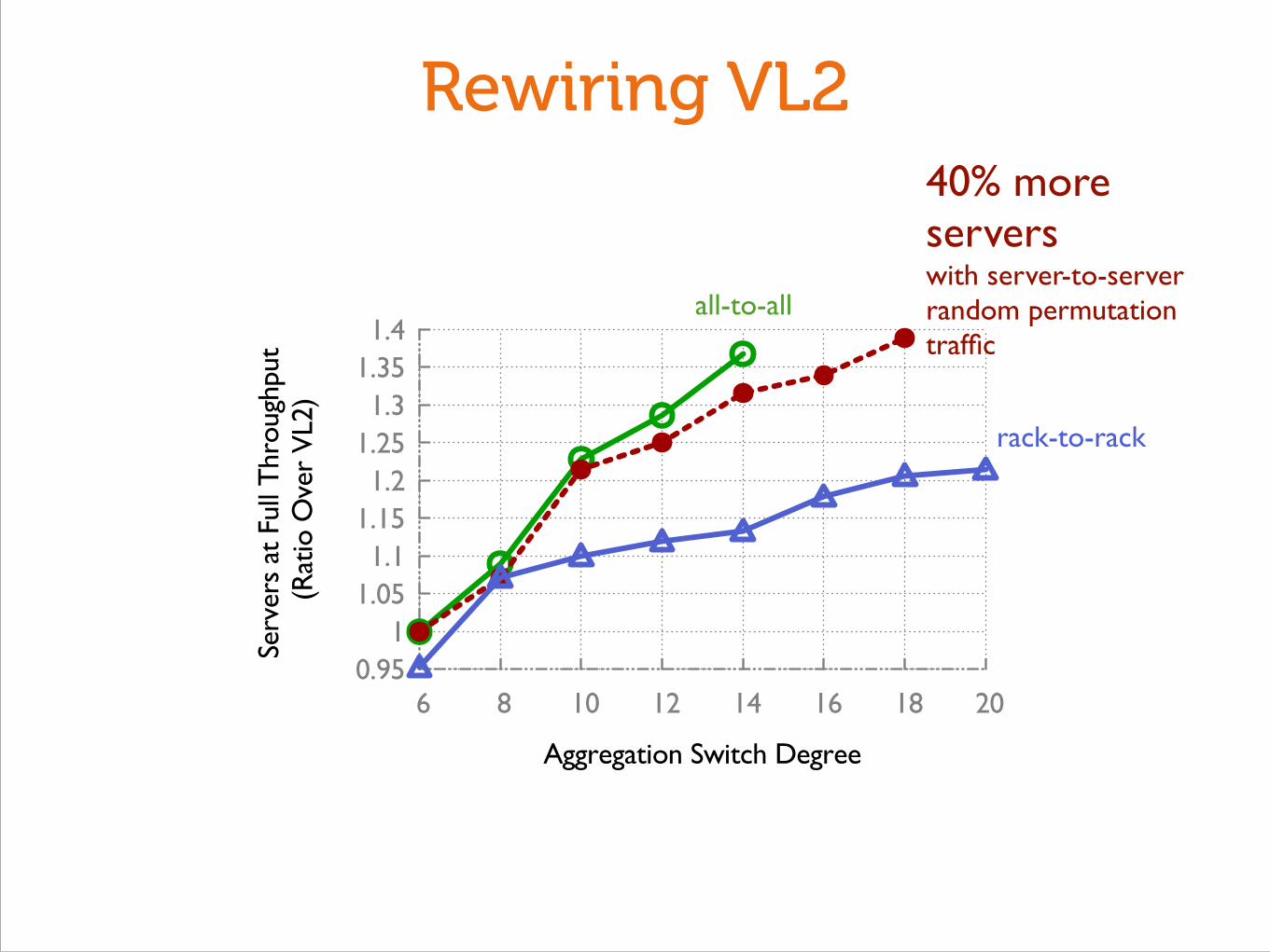
Rewiring VL2
0.95 1
1.05 1.1
1.15 1.2
1.25 1.3
1.35 1.4
6 8 10 12 14 16 18 20
Serv
ers
at F
ull T
hrou
ghpu
t (R
atio
Ove
r V
L2)
Aggregation Switch Degree
40% more servers with server-to-server random permutation traffic

Rewiring VL2
0.95 1
1.05 1.1
1.15 1.2
1.25 1.3
1.35 1.4
6 8 10 12 14 16 18 20
Serv
ers
at F
ull T
hrou
ghpu
t (R
atio
Ove
r V
L2)
Aggregation Switch Degree
rack-to-rack
40% more servers with server-to-server random permutation traffic
Rewiring VL2
0.95 1
1.05 1.1
1.15 1.2
1.25 1.3
1.35 1.4
6 8 10 12 14 16 18 20
Serv
ers
at F
ull T
hrou
ghpu
t (R
atio
Ove
r V
L2)
Aggregation Switch Degree
all-to-all
rack-to-rack
40% more servers with server-to-server random permutation traffic
https://github.com/ankitsingla/topobench
How do we design throughput optimal network topologies?