Embed Size (px)
Citation preview
Turbomachinery Propulsion and Power
International Journal of
Article
High-Temperature Profile Monitoring in Gas TurbineExhaust-Gas Diffusors with Six-Point Fiber-OpticSensor Array
Franz J. Dutz 1,* , Sven Boje 2, Ulrich Orth 2, Alexander W. Koch 3 and Johannes Roths 1,*1 Photonics Laboratory, Munich University of Applied Sciences, Lothstrasse 34, 80335 Munich, Germany2 MAN Energy Solutions SE, Steinbrinkstrasse 1, 46145 Oberhausen, Germany; [email protected] (S.B.);
[email protected] (U.O.)3 Institute for Measurement Systems and Sensor Technology, Technical University of Munich,
Theresienstrasse 90, 80333 Munich, Germany; [email protected]* Correspondence: [email protected] (F.J.D.); [email protected] (J.R.);
Tel.: +49-(0)89-1265-3654 (F.J.D.); +49-(0)89-1265-1658 (J.R.)
Received: 26 March 2020; Accepted: 21 September 2020; Published: 24 September 2020�����������������
Abstract: In this paper, the deployment of a newly developed, multipoint, fiber-optic temperature-sensor system for temperature distribution measurements in a 6 MW gas turbine is demonstrated.The optical sensor fiber was integrated in a stainless steel protection cable with a 1.6 mm outsidediameter. It included six measurement points, distributed over a length of 110 mm. The sensor cablewas mounted in a temperature probe and was positioned radially in the exhaust-gas diffusor of theturbine. With this temperature probe, the radial temperature profiles in the exhaust-gas diffusor weremeasured with high spatial and temporal resolution. During a test run of the turbine, characteristictemperature gradients were observed when the machine operated at different loads.
Keywords: fiber Bragg grating; multipoint; high temperature; regenerated grating; gas turbine
1. Introduction
Due to its improved maturity and reliability, fiber-optic temperature sensing based on fiber Bragggratings (FBGs) is becoming more and more interesting for real-world applications. FBGs are chemicallyinert and immune to electromagnetic interference and exhibit a small size. Probably, the most importantfeature for industrial applications relates to their multiplexing capability. This enables the realizationof several tens of temperature measurement points consecutively located in a single fiber and bringsdown the cabling efforts and the associated obstructions of the air-gas streams due to sensor wiring.Therefore, multipoint FBG technology allows an unprecedented density of temperature measurementpoints when compared to conventional approaches based on electrical sensors, e.g., thermocouples.
In some of the industrial applications that would benefit from using multipoint FBG sensors,temperatures exceed 400 ◦C. Here, common type I FBGs are not suitable because they strongly degrade atelevated temperatures. Instead, FBG types capable of resisting high temperatures, such as femtosecondlaser-inscribed FBGs [1,2], chemical composition gratings [3,4], and regenerated gratings [5,6], come intooperation. Packaging techniques, calibration procedures and temperature drifts strongly influencethe functionality and performance of FBG sensors. For the measurements presented here, we usedregenerated FBGs (RFBGs), which emerge from type I FBGs in H2-loaded fibers when subjected toa special annealing process. RFBGs can be used at temperatures up to 1200 ◦C [7]. Applications ofmultipoint sensing based on high-temperature FBGs have been reported for combustor systems [8],nuclear reactors [9], chemical reactors [10,11], and gas turbines [10,12,13].
Int. J. Turbomach. Propuls. Power 2020, 5, 25; doi:10.3390/ijtpp5040025 www.mdpi.com/journal/ijtpp
Int. J. Turbomach. Propuls. Power 2020, 5, 25 2 of 6
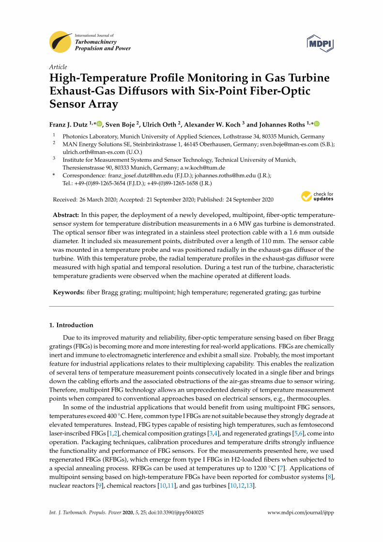
In gas turbines, temperature measurements in the hot exhaust gas are used to control and protectthe turbine. It is of paramount importance that these measurements are accurate and reliable for years,even under rough site conditions (e.g., deserts or offshore). To date, state-of-the-art thermocoupleswith tolerance class 1 and a resulting temperature uncertainty of about 2 K at 500 ◦C have been used tomeasure temperatures in the gas turbine flow path. However, during R&D tests at a test bed, a shorterlifetime (in the range of months) with a defined accuracy and a limited drift is acceptable. Here,the recording of temperature profiles in the exhaust gas with high local resolution under different loadconditions is of great interest. For this task, multipoint fiber-optic sensors based on RFBGs can be usedat locations where the installation of a multitude of conventional sensors is not possible due to sizeand cabling efforts. Additionally, less influence on gas flows is expected due to the small diameter ofthe fibers. MAN Energy Solutions produces, amongst other turbomachines, the MGT6000 gas turbinein the power class of 6 MW. The twin-shaft version is mainly used to drive natural gas compressorsor pumps in the oil and gas industry. The single-shaft version is best suited for combined heat andelectricity generation (so-called CHP processes) in smaller installations such as paper mills or carfactories. As both heat and power are produced by the same installation, the overall efficiency andeconomy are maximized compared to those of separate generation.
Here, we demonstrate the application of a six-point fiber-optic sensor array based on RFBGsfor monitoring the radial temperature profile in the exhaust-gas diffusor of a MGT6000 gas turbine(see Figure 1). For the measurements, the RFBG array was mounted in a probe made of Inconel.Characteristic temperature profiles were measured when the gas turbine was operated at different loads.
Int. J. Turbomach. Propuls. Power 2020, 5, x FOR PEER REVIEW 2 of 6
In gas turbines, temperature measurements in the hot exhaust gas are used to control and protect the turbine. It is of paramount importance that these measurements are accurate and reliable for years, even under rough site conditions (e.g., deserts or offshore). To date, state-of-the-art thermocouples with tolerance class 1 and a resulting temperature uncertainty of about 2 K at 500 °C have been used to measure temperatures in the gas turbine flow path. However, during R&D tests at a test bed, a shorter lifetime (in the range of months) with a defined accuracy and a limited drift is acceptable. Here, the recording of temperature profiles in the exhaust gas with high local resolution under different load conditions is of great interest. For this task, multipoint fiber-optic sensors based on RFBGs can be used at locations where the installation of a multitude of conventional sensors is not possible due to size and cabling efforts. Additionally, less influence on gas flows is expected due to the small diameter of the fibers. MAN Energy Solutions produces, amongst other turbomachines, the MGT6000 gas turbine in the power class of 6 MW. The twin-shaft version is mainly used to drive natural gas compressors or pumps in the oil and gas industry. The single-shaft version is best suited for combined heat and electricity generation (so-called CHP processes) in smaller installations such as paper mills or car factories. As both heat and power are produced by the same installation, the overall efficiency and economy are maximized compared to those of separate generation.
Here, we demonstrate the application of a six-point fiber-optic sensor array based on RFBGs for monitoring the radial temperature profile in the exhaust-gas diffusor of a MGT6000 gas turbine (see Figure 1). For the measurements, the RFBG array was mounted in a probe made of Inconel. Characteristic temperature profiles were measured when the gas turbine was operated at different loads.
Figure 1. Gas turbine MGT6000 (MAN Energy Solutions SE, Oberhausen, Germany).
2. Methodology and Measurement Setup
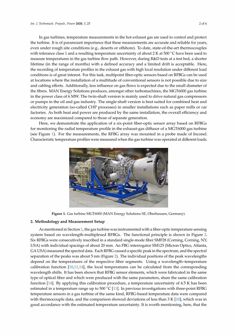
As mentioned in Section 1, the gas turbine was instrumented with a fiber-optic temperature-sensing system based on wavelength-multiplexed RFBGs. The functional principle is shown in Figure 2. Six RFBGs were consecutively inscribed in a standard single-mode fiber SMF28 (Corning, Corning, NY, USA) with individual spacings of about 20 mm. An FBG interrogator SM125 (Micron Optics, Atlanta, GA USA) measured the spectral data. Each RFBG caused a specific peak in the spectrum, and the spectral separation of the peaks was about 5 nm (Figure 2). The individual positions of the peak wavelengths depend on the temperatures of the respective fiber segments. Using a wavelength–temperature calibration function [10,11,14], the local temperatures can be calculated from the corresponding wavelength shifts. It has been shown that RFBG sensor elements, which were fabricated in the same type of optical fiber and which were produced with the same parameters, share the same calibration function [14]. By applying this calibration procedure, a temperature uncertainty of 4.5 K has been estimated in a temperature range up to 500 °C [11]. In previous investigations with three-point RFBG temperature sensors in a gas turbine of the same kind, RFBG-based temperature data were compared with thermocouple data, and the comparison showed deviations of less than 3 K [10], which was in good accordance with the estimated temperature uncertainty. It is worth mentioning,
Figure 1. Gas turbine MGT6000 (MAN Energy Solutions SE, Oberhausen, Germany).
2. Methodology and Measurement Setup
As mentioned in Section 1, the gas turbine was instrumented with a fiber-optic temperature-sensingsystem based on wavelength-multiplexed RFBGs. The functional principle is shown in Figure 2.Six RFBGs were consecutively inscribed in a standard single-mode fiber SMF28 (Corning, Corning, NY,USA) with individual spacings of about 20 mm. An FBG interrogator SM125 (Micron Optics, Atlanta,GA USA) measured the spectral data. Each RFBG caused a specific peak in the spectrum, and the spectralseparation of the peaks was about 5 nm (Figure 2). The individual positions of the peak wavelengthsdepend on the temperatures of the respective fiber segments. Using a wavelength–temperaturecalibration function [10,11,14], the local temperatures can be calculated from the correspondingwavelength shifts. It has been shown that RFBG sensor elements, which were fabricated in the sametype of optical fiber and which were produced with the same parameters, share the same calibrationfunction [14]. By applying this calibration procedure, a temperature uncertainty of 4.5 K has beenestimated in a temperature range up to 500 ◦C [11]. In previous investigations with three-point RFBGtemperature sensors in a gas turbine of the same kind, RFBG-based temperature data were comparedwith thermocouple data, and the comparison showed deviations of less than 3 K [10], which was ingood accordance with the estimated temperature uncertainty. It is worth mentioning, here, that the
Int. J. Turbomach. Propuls. Power 2020, 5, 25 3 of 6
maximum number of RFBGs is not generally limited to six; several tens of temperature measurementpoints are possible.
Int. J. Turbomach. Propuls. Power 2020, 5, x FOR PEER REVIEW 3 of 6
here, that the maximum number of RFBGs is not generally limited to six; several tens of temperature measurement points are possible.
Figure 2. Principle of fiber Bragg grating (FBG) multiplexing.
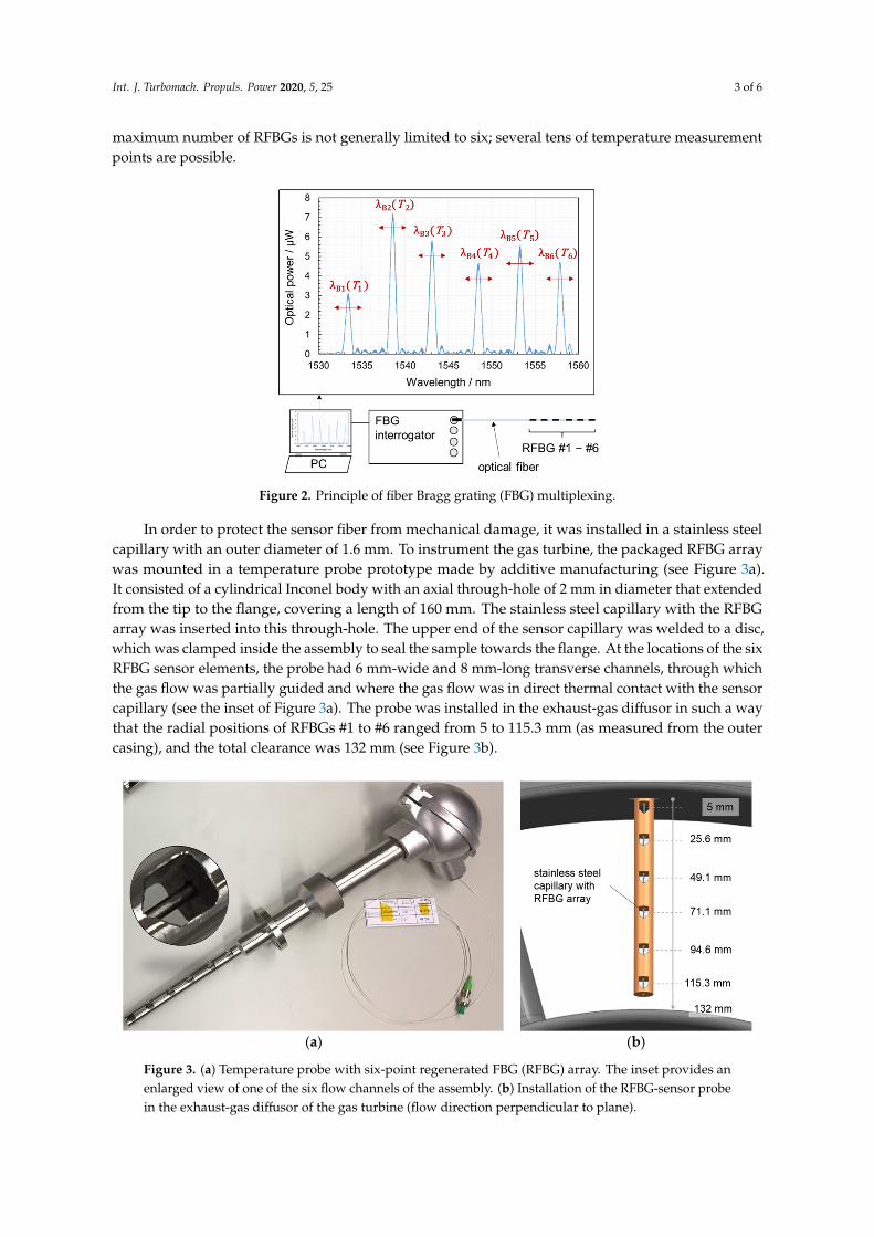
In order to protect the sensor fiber from mechanical damage, it was installed in a stainless steel capillary with an outer diameter of 1.6 mm. To instrument the gas turbine, the packaged RFBG array was mounted in a temperature probe prototype made by additive manufacturing (see Figure 3a). It consisted of a cylindrical Inconel body with an axial through-hole of 2 mm in diameter that extended from the tip to the flange, covering a length of 160 mm. The stainless steel capillary with the RFBG array was inserted into this through-hole. The upper end of the sensor capillary was welded to a disc, which was clamped inside the assembly to seal the sample towards the flange. At the locations of the six RFBG sensor elements, the probe had 6 mm-wide and 8 mm-long transverse channels, through which the gas flow was partially guided and where the gas flow was in direct thermal contact with the sensor capillary (see the inset of Figure 3a). The probe was installed in the exhaust-gas diffusor in such a way that the radial positions of RFBGs #1 to #6 ranged from 5 to 115.3 mm (as measured from the outer casing), and the total clearance was 132 mm (see Figure 3b).
(a) (b)
Figure 3. (a) Temperature probe with six-point regenerated FBG (RFBG) array. The inset provides an enlarged view of one of the six flow channels of the assembly. (b) Installation of the RFBG-sensor probe in the exhaust-gas diffusor of the gas turbine (flow direction perpendicular to plane).
Figure 2. Principle of fiber Bragg grating (FBG) multiplexing.
In order to protect the sensor fiber from mechanical damage, it was installed in a stainless steelcapillary with an outer diameter of 1.6 mm. To instrument the gas turbine, the packaged RFBG arraywas mounted in a temperature probe prototype made by additive manufacturing (see Figure 3a).It consisted of a cylindrical Inconel body with an axial through-hole of 2 mm in diameter that extendedfrom the tip to the flange, covering a length of 160 mm. The stainless steel capillary with the RFBGarray was inserted into this through-hole. The upper end of the sensor capillary was welded to a disc,which was clamped inside the assembly to seal the sample towards the flange. At the locations of the sixRFBG sensor elements, the probe had 6 mm-wide and 8 mm-long transverse channels, through whichthe gas flow was partially guided and where the gas flow was in direct thermal contact with the sensorcapillary (see the inset of Figure 3a). The probe was installed in the exhaust-gas diffusor in such a waythat the radial positions of RFBGs #1 to #6 ranged from 5 to 115.3 mm (as measured from the outercasing), and the total clearance was 132 mm (see Figure 3b).
Int. J. Turbomach. Propuls. Power 2020, 5, x FOR PEER REVIEW 3 of 6
here, that the maximum number of RFBGs is not generally limited to six; several tens of temperature measurement points are possible.
Figure 2. Principle of fiber Bragg grating (FBG) multiplexing.
In order to protect the sensor fiber from mechanical damage, it was installed in a stainless steel capillary with an outer diameter of 1.6 mm. To instrument the gas turbine, the packaged RFBG array was mounted in a temperature probe prototype made by additive manufacturing (see Figure 3a). It consisted of a cylindrical Inconel body with an axial through-hole of 2 mm in diameter that extended from the tip to the flange, covering a length of 160 mm. The stainless steel capillary with the RFBG array was inserted into this through-hole. The upper end of the sensor capillary was welded to a disc, which was clamped inside the assembly to seal the sample towards the flange. At the locations of the six RFBG sensor elements, the probe had 6 mm-wide and 8 mm-long transverse channels, through which the gas flow was partially guided and where the gas flow was in direct thermal contact with the sensor capillary (see the inset of Figure 3a). The probe was installed in the exhaust-gas diffusor in such a way that the radial positions of RFBGs #1 to #6 ranged from 5 to 115.3 mm (as measured from the outer casing), and the total clearance was 132 mm (see Figure 3b).
(a) (b)
Figure 3. (a) Temperature probe with six-point regenerated FBG (RFBG) array. The inset provides an enlarged view of one of the six flow channels of the assembly. (b) Installation of the RFBG-sensor probe in the exhaust-gas diffusor of the gas turbine (flow direction perpendicular to plane).
Figure 3. (a) Temperature probe with six-point regenerated FBG (RFBG) array. The inset provides anenlarged view of one of the six flow channels of the assembly. (b) Installation of the RFBG-sensor probein the exhaust-gas diffusor of the gas turbine (flow direction perpendicular to plane).
Int. J. Turbomach. Propuls. Power 2020, 5, 25 4 of 6
3. Results of High-Temperature Measurements
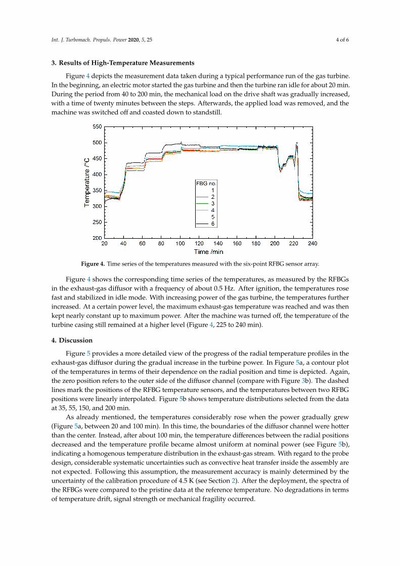
Figure 4 depicts the measurement data taken during a typical performance run of the gas turbine.In the beginning, an electric motor started the gas turbine and then the turbine ran idle for about 20 min.During the period from 40 to 200 min, the mechanical load on the drive shaft was gradually increased,with a time of twenty minutes between the steps. Afterwards, the applied load was removed, and themachine was switched off and coasted down to standstill.
Int. J. Turbomach. Propuls. Power 2020, 5, x FOR PEER REVIEW 4 of 6
3. Results of High-Temperature Measurements
Figure 4 depicts the measurement data taken during a typical performance run of the gas turbine. In the beginning, an electric motor started the gas turbine and then the turbine ran idle for about 20 min. During the period from 40 to 200 min, the mechanical load on the drive shaft was gradually increased, with a time of twenty minutes between the steps. Afterwards, the applied load was removed, and the machine was switched off and coasted down to standstill.
Figure 4 shows the corresponding time series of the temperatures, as measured by the RFBGs in the exhaust-gas diffusor with a frequency of about 0.5 Hz. After ignition, the temperatures rose fast and stabilized in idle mode. With increasing power of the gas turbine, the temperatures further increased. At a certain power level, the maximum exhaust-gas temperature was reached and was then kept nearly constant up to maximum power. After the machine was turned off, the temperature of the turbine casing still remained at a higher level (Figure 4, 225 to 240 min).
Figure 4. Time series of the temperatures measured with the six-point RFBG sensor array.
4. Discussion
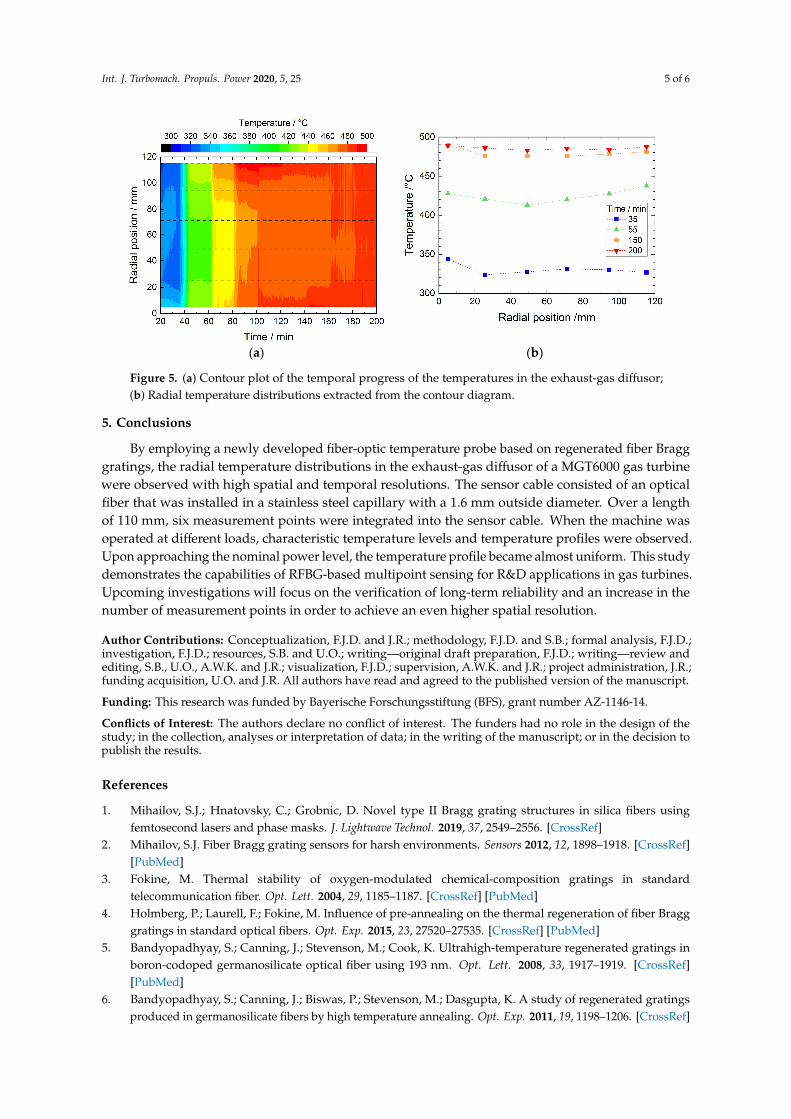
Figure 5 provides a more detailed view of the progress of the radial temperature profiles in the exhaust-gas diffusor during the gradual increase in the turbine power. In Figure 5a, a contour plot of the temperatures in terms of their dependence on the radial position and time is depicted. Again, the zero position refers to the outer side of the diffusor channel (compare with Figure 3b). The dashed lines mark the positions of the RFBG temperature sensors, and the temperatures between two RFBG positions were linearly interpolated. Figure 5b shows temperature distributions selected from the data at 35, 55, 150, and 200 min.
As already mentioned, the temperatures considerably rose when the power gradually grew (Figure 5a, between 20 and 100 min). In this time, the boundaries of the diffusor channel were hotter than the center. Instead, after about 100 min, the temperature differences between the radial positions decreased and the temperature profile became almost uniform at nominal power (see Figure 5b), indicating a homogenous temperature distribution in the exhaust-gas stream. With regard to the probe design, considerable systematic uncertainties such as convective heat transfer inside the assembly are not expected. Following this assumption, the measurement accuracy is mainly determined by the uncertainty of the calibration procedure of 4.5 K (see Section 2). After the deployment, the spectra of the RFBGs were compared to the pristine data at the reference temperature. No degradations in terms of temperature drift, signal strength or mechanical fragility occurred.
Figure 4. Time series of the temperatures measured with the six-point RFBG sensor array.
Figure 4 shows the corresponding time series of the temperatures, as measured by the RFBGsin the exhaust-gas diffusor with a frequency of about 0.5 Hz. After ignition, the temperatures rosefast and stabilized in idle mode. With increasing power of the gas turbine, the temperatures furtherincreased. At a certain power level, the maximum exhaust-gas temperature was reached and was thenkept nearly constant up to maximum power. After the machine was turned off, the temperature of theturbine casing still remained at a higher level (Figure 4, 225 to 240 min).
4. Discussion
Figure 5 provides a more detailed view of the progress of the radial temperature profiles in theexhaust-gas diffusor during the gradual increase in the turbine power. In Figure 5a, a contour plotof the temperatures in terms of their dependence on the radial position and time is depicted. Again,the zero position refers to the outer side of the diffusor channel (compare with Figure 3b). The dashedlines mark the positions of the RFBG temperature sensors, and the temperatures between two RFBGpositions were linearly interpolated. Figure 5b shows temperature distributions selected from the dataat 35, 55, 150, and 200 min.
As already mentioned, the temperatures considerably rose when the power gradually grew(Figure 5a, between 20 and 100 min). In this time, the boundaries of the diffusor channel were hotterthan the center. Instead, after about 100 min, the temperature differences between the radial positionsdecreased and the temperature profile became almost uniform at nominal power (see Figure 5b),indicating a homogenous temperature distribution in the exhaust-gas stream. With regard to the probedesign, considerable systematic uncertainties such as convective heat transfer inside the assembly arenot expected. Following this assumption, the measurement accuracy is mainly determined by theuncertainty of the calibration procedure of 4.5 K (see Section 2). After the deployment, the spectra ofthe RFBGs were compared to the pristine data at the reference temperature. No degradations in termsof temperature drift, signal strength or mechanical fragility occurred.
Int. J. Turbomach. Propuls. Power 2020, 5, 25 5 of 6Int. J. Turbomach. Propuls. Power 2020, 5, x FOR PEER REVIEW 5 of 6
(a) (b)
Figure 5. (a) Contour plot of the temporal progress of the temperatures in the exhaust-gas diffusor; (b) Radial temperature distributions extracted from the contour diagram.
5. Conclusions
By employing a newly developed fiber-optic temperature probe based on regenerated fiber Bragg gratings, the radial temperature distributions in the exhaust-gas diffusor of a MGT6000 gas turbine were observed with high spatial and temporal resolutions. The sensor cable consisted of an optical fiber that was installed in a stainless steel capillary with a 1.6 mm outside diameter. Over a length of 110 mm, six measurement points were integrated into the sensor cable. When the machine was operated at different loads, characteristic temperature levels and temperature profiles were observed. Upon approaching the nominal power level, the temperature profile became almost uniform. This study demonstrates the capabilities of RFBG-based multipoint sensing for R&D applications in gas turbines. Upcoming investigations will focus on the verification of long-term reliability and an increase in the number of measurement points in order to achieve an even higher spatial resolution.
Author Contributions: Conceptualization, F.J.D. and J.R.; methodology, F.J.D. and S.B.; formal analysis, F.J.D.; investigation, F.J.D.; resources, S.B. and U.O.; writing—original draft preparation, F.J.D.; writing—review and editing, S.B., U.O., A.W.K. and J.R.; visualization, F.J.D.; supervision, A.W.K. and J.R.; project administration, J.R.; funding acquisition, U.O. and J.R. All authors have read and agreed to the published version of the manuscript.
Funding: This research was funded by Bayerische Forschungsstiftung (BFS), grant number AZ-1146-14.
Conflicts of Interest: The authors declare no conflict of interest. The funders had no role in the design of the study; in the collection, analyses or interpretation of data; in the writing of the manuscript; or in the decision to publish the results.
References
1. Mihailov, S.J.; Hnatovsky, C.; Grobnic, D. Novel type II Bragg grating structures in silica fibers using femtosecond lasers and phase masks. J. Lightwave Technol. 2019, 37, 2549–2556, doi:10.1109/JLT.2018.2866784.
2. Mihailov, S.J. Fiber Bragg grating sensors for harsh environments. Sensors 2012, 12, 1898–1918, doi:10.3390/s120201898.
3. Fokine, M. Thermal stability of oxygen-modulated chemical-composition gratings in standard telecommunication fiber. Opt. Lett. 2004, 29, 1185–1187, doi:10.1364/OL.29.001185.
4. Holmberg, P.; Laurell, F.; Fokine, M. Influence of pre-annealing on the thermal regeneration of fiber Bragg gratings in standard optical fibers. Opt. Exp. 2015, 23, 27520–27535.
Figure 5. (a) Contour plot of the temporal progress of the temperatures in the exhaust-gas diffusor;(b) Radial temperature distributions extracted from the contour diagram.
5. Conclusions
By employing a newly developed fiber-optic temperature probe based on regenerated fiber Bragggratings, the radial temperature distributions in the exhaust-gas diffusor of a MGT6000 gas turbinewere observed with high spatial and temporal resolutions. The sensor cable consisted of an opticalfiber that was installed in a stainless steel capillary with a 1.6 mm outside diameter. Over a lengthof 110 mm, six measurement points were integrated into the sensor cable. When the machine wasoperated at different loads, characteristic temperature levels and temperature profiles were observed.Upon approaching the nominal power level, the temperature profile became almost uniform. This studydemonstrates the capabilities of RFBG-based multipoint sensing for R&D applications in gas turbines.Upcoming investigations will focus on the verification of long-term reliability and an increase in thenumber of measurement points in order to achieve an even higher spatial resolution.
Author Contributions: Conceptualization, F.J.D. and J.R.; methodology, F.J.D. and S.B.; formal analysis, F.J.D.;investigation, F.J.D.; resources, S.B. and U.O.; writing—original draft preparation, F.J.D.; writing—review andediting, S.B., U.O., A.W.K. and J.R.; visualization, F.J.D.; supervision, A.W.K. and J.R.; project administration, J.R.;funding acquisition, U.O. and J.R. All authors have read and agreed to the published version of the manuscript.
Funding: This research was funded by Bayerische Forschungsstiftung (BFS), grant number AZ-1146-14.
Conflicts of Interest: The authors declare no conflict of interest. The funders had no role in the design of thestudy; in the collection, analyses or interpretation of data; in the writing of the manuscript; or in the decision topublish the results.
References
1. Mihailov, S.J.; Hnatovsky, C.; Grobnic, D. Novel type II Bragg grating structures in silica fibers usingfemtosecond lasers and phase masks. J. Lightwave Technol. 2019, 37, 2549–2556. [CrossRef]
2. Mihailov, S.J. Fiber Bragg grating sensors for harsh environments. Sensors 2012, 12, 1898–1918. [CrossRef][PubMed]
3. Fokine, M. Thermal stability of oxygen-modulated chemical-composition gratings in standardtelecommunication fiber. Opt. Lett. 2004, 29, 1185–1187. [CrossRef] [PubMed]
4. Holmberg, P.; Laurell, F.; Fokine, M. Influence of pre-annealing on the thermal regeneration of fiber Bragggratings in standard optical fibers. Opt. Exp. 2015, 23, 27520–27535. [CrossRef] [PubMed]
5. Bandyopadhyay, S.; Canning, J.; Stevenson, M.; Cook, K. Ultrahigh-temperature regenerated gratings inboron-codoped germanosilicate optical fiber using 193 nm. Opt. Lett. 2008, 33, 1917–1919. [CrossRef][PubMed]
6. Bandyopadhyay, S.; Canning, J.; Biswas, P.; Stevenson, M.; Dasgupta, K. A study of regenerated gratingsproduced in germanosilicate fibers by high temperature annealing. Opt. Exp. 2011, 19, 1198–1206. [CrossRef]
Int. J. Turbomach. Propuls. Power 2020, 5, 25 6 of 6
7. Canning, J.; Stevenson, M.; Bandyopadhyay, S.; Cook, K. Extreme silica optical fibre gratings. Sensors 2008,8, 6448–6452. [CrossRef] [PubMed]
8. Mihailov, S.J.; Grobnic, D.; Hnatovsky, C.; Walker, R.B.; Lu, P.; Coulas, D.; Ding, H. Extreme environmentsensing using femtosecond laser-inscribed fiber Bragg gratings. Sensors 2017, 17, 2909. [CrossRef] [PubMed]
9. Laffont, G.; Cotillard, R.; Roussel, N.; Desmarchelier, R.; Rougeault, S. Temperature resistant fiber Bragggratings for on-line and structural health monitoring of the next-generation of nuclear reactors. Sensors 2018,18, 1791. [CrossRef] [PubMed]
10. Dutz, F.J.; Lindner, M.; Heinrich, A.; Seydel, C.G.; Bosselmann, T.; Koch, A.W.; Roths, J. Multipoint hightemperature sensing with regenerated fiber Bragg gratings. Proc. SPIE 2018, 10654, 1065407. [CrossRef]
11. Dutz, F.J.; Heinrich, A.; Bank, R.; Koch, A.W.; Roths, J. Fiber-optic multipoint sensor system with low driftfor the long-term monitoring of high-temperature distributions in chemical reactors. Sensors 2019, 19, 5476.[CrossRef] [PubMed]
12. Willsch, M.; Bosselmann, T.; Flohr, P.; Kull, R.; Ecke, W.; Latka, I.; Fischer, D.; Thiel, T. Design of fiber opticalhigh temperature sensors for gas turbine monitoring. Proc. SPIE 2009, 7503, 75037R. [CrossRef]
13. Xia, H.; Byrd, D.; Dekate, S.; Lee, B. High-density fiber optical sensor and instrumentation for gas turbineoperation condition monitoring. J. Sens. 2013, 2013, 1–10. [CrossRef]
14. Lindner, M.; Tunc, E.; Weraneck, K.; Heilmeier, F.; Volk, W.; Jakobi, M.; Koch, A.W.; Roths, J. RegeneratedBragg grating sensor array for temperature measurements during an aluminum casting process. IEEE Sens. J.2018, 18, 5352–5360. [CrossRef]
© 2020 by the authors. Licensee MDPI, Basel, Switzerland. This article is an open accessarticle distributed under the terms and conditions of the Creative Commons Attribution(CC BY-NC-ND) license (http://creativecommons.org/licenses/by-nc-nd/4.0/).