Embed Size (px)
Citation preview

Publications (NSTD) Nuclear Science & Technology Division
9-30-2008
High Temperature Heat Exchanger Annual Report High Temperature Heat Exchanger Annual Report
Anthony Hechanova University of Nevada, Las Vegas, [email protected]
Follow this and additional works at: https://digitalscholarship.unlv.edu/hrc_nstd_pubs
Part of the Heat Transfer, Combustion Commons, Materials Science and Engineering Commons, and
the Nuclear Engineering Commons
Repository Citation Repository Citation Hechanova, A. (2008). High Temperature Heat Exchanger Annual Report. 1-38. Available at:Available at: https://digitalscholarship.unlv.edu/hrc_nstd_pubs/6
This Annual Report is protected by copyright and/or related rights. It has been brought to you by Digital Scholarship@UNLV with permission from the rights-holder(s). You are free to use this Annual Report in any way that is permitted by the copyright and related rights legislation that applies to your use. For other uses you need to obtain permission from the rights-holder(s) directly, unless additional rights are indicated by a Creative Commons license in the record and/or on the work itself. This Annual Report has been accepted for inclusion in Publications (NSTD) by an authorized administrator of Digital Scholarship@UNLV. For more information, please contact [email protected].
1
High Temperature Heat Exchanger Annual Report Anthony Hechanova University of Nevada, Las Vegas 4505 Maryland Parkway, Box 454009 Las Vegas, NV 89154-4009 (702) 895-1457; fax (702) 895-2354; [email protected] DOE Technology Development Manager: David Henderson (301) 903-3097; fax (301) 903-5057; [email protected] DOE Project Officer: Carl Sink (301) 903-5131; fax (301) 903-5084; [email protected] Technical Advisor: Steven Sherman (208) 533-7327; [email protected] Contract Number: DE-FC07-04ID14566 Subcontractors: University of Nevada Las Vegas, Las Vegas, Nevada General Atomics, La Jolla, California University of California Berkeley, Berkeley, California Massachusetts Institute of Technology, Cambridge, Massachusetts Ceramatec, Inc., Salt Lake City, Utah Start Date: 10/3/2003 Projected End Date: 9/30/2008 Objectives
• Identify candidate materials for heat exchanger components. • Test candidate materials for heat exchanger components. • Design critical components in the interface between the reactor and hydrogen production
plant and within the sulfur iodine thermochemical process. • Fabricate prototypical components. • Test prototypical components.
Technical Barriers This project addresses the following technical barriers of the Nuclear Hydrogen Initiative:
• Development of high-temperature, corrosion resistant materials • Development of high-temperature, high-activity, stable catalysts • Development of compact, cost-effective heat exchanger components • Achievement of reasonable performance of small-scale experiments
Approach
• Identify candidate metallic and ceramic materials based on reasonable expectations of the material properties.
• Identify candidate structural alloy for self-catalytic material.
2
• Characterize self catalytic materials (chemical, electrochemical, mechanical properties). • Design and fabricate heat exchanger test article using self catalytic materials. • Test heat exchanger under prototypic conditions. • Screen candidate metallic and ceramic materials for compatibility in hydrogen iodide
using short-term corrosion performance experiments. • Screen candidate ceramic materials for compatibility in the sulfuric acid decomposer
based on data in the literature and data generated from the sulfuric acid exposure test rig. • Test candidate metallic and ceramic materials in long-term corrosion performance
experiments. • Test candidate metallic materials for corrosion resistance and mechanical properties using
tensile, constant load, and slow strain rate machines. • Perform fractographic evaluations and surface analysis of candidate metallic materials
using spectroscopy. • Demonstrate fabrication methods of ceramic heat exchangers. • Design compact and efficient heat exchangers for challenging components, in particular,
the intermediate heat exchanger, the sulfuric acid decomposition heat exchangers, and the hydrogen iodide decomposition heat exchangers.
• Perform numerical simulation model of candidate heat exchanger designs. • Perform hydrodynamic and heat transfer simulations on candidate heat exchanger designs
to develop baseline designs. • Perform parametric studies using computational fluid dynamic techniques to optimize
heat exchanger designs. • Perform numerical stress analyses on candidate heat exchanger designs.
Accomplishments
• A micro-channel plate design heat exchanger was designed for helium-to-sulfuric acid heat transfer.
• 22 coupons from four classes of materials (refractory and reactive metals, superalloys, and ceramics) were screened for 100 hours or more each in liquid HIx. Suitable candidates for the HI decomposition heat exchanger include Nb-1Zr, Ta-7.5Nb, and SiC.
• High pressure helium permeation testing verified very good helium hermeticity of several types of melt infiltrated (MI) composite materials; Young’s moduli of three types of MI materials were measured.
• Methods to make heat exchanger plates from chopped carbon fiber reinforced SiC composite material with polymer infiltration and pyrolysis (PIP) process were surveyed. Experimental tries are being performed with die embossed methods.
• Thermal and stress analysis for the baseline ceramic compact off-set strip fin heat exchanger were performed to identify optimal designs for core heat transfer unit, inlet and outlet manifolds, distribution channels, and channel dividers. High stresses regions were found.
• An initial survey of liquid fluoride salt additives for chemical control was completed. The additives react with and consume sulfuric acid so that it is possible to permit the safe use of liquid salts for high-temperature heat transport without double-wall S-I process heat exchangers.
3
• Completed microstructural and electrochemical characterization of self catalytic materials based on Alloy 800 and 617 with added Pt.
• Selected base alloy compositions for further use in the program. Based on Alloy 600 and 617 with 1-2 wt% Pt added
• Designed and began construction of catalytic effectiveness system for testing catalytic materials.
• Completed preliminary design of compact heat exchanger test article to be fabricated using catalytic materials.
• Grid independence and turbulent modeling have been studied in order to obtain the proper numerical results and physics for the compact off-set strip fin high temperature heat exchanger (HTHX).
• Optimization studies of ceramic compact off-set strip fin HTHX were performed using computational fluid dynamics (CFD) modeling for pressure drop and thermal performance for varied channel dimensions.
• The pressure drop and thermal performance due to fillets from manufacturing process were studied.
• The stress analyses of the compact off-set strip fin HTHX were performed. The mechanical stresses and thermal stresses were studied.
• A two-dimensional numerical model was used to study the effect of different parameters such as wall surface temperature, diameter of the reactor tube, length of the reactor tube and mole flow rate at the inlet of the reactor tube for the sulfur trioxide decomposition heat exchanger.
• The numerical results obtained from the sulfur trioxide decomposition heat exchanger based on catalytic reactions have been compared with the experimental results provided by Idaho National Laboratory.
Future Directions
• Test candidate metallic materials (Incoloy 800H, Nb-1Zr, Nb-7.5Ta, and Zr 705) for high temperature corrosion and material properties.
• Perform experimental testing to validate numerical modeling of the heat exchangers. • Perform long-term coupon testing in HIx. • Conduct tests to study the effect of HIx on stress corrosion behavior of materials. • Study the effects of crack growth in candidate materials. • Evaluate material cost reduction through cladding. • Continue the identification and demonstration of candidate ceramic heat exchanger
materials and fabrication methods, with a continuing focus on low-cost chopped carbon fiber reinforced silicon carbide, where the silicon carbide is infiltrated by either MI or PIP, and where additional low-cost filler materials may be used. Confirm helium permeation resistance. Confirm carbon CVD coating capability for interior flow passages. Scale size and design to demonstrate for interior flow passages.
• Continue to refine mechanical design, thermal hydraulic calculation, and steady and transient thermal stress analysis for ceramic heat exchangers.
• Continue to study chemical and tritium safety and corrosion control methods in ceramic heat exchangers with liquid salt as heat transfer fluid.
• Fabricate and characterize larger heats of Alloy 800HT and Alloy 617 with 2% weight Pt.

4
• Finish construction of catalyst effectiveness system. This will be completed early in FY06
• Finish design of compact heart exchanger. • Initiate the unsteady flow studies using CFD techniques on the off-set strip fin heat
exchanger design. • Study the effect of the hydraulic diameters on the pressure drop and thermal performance. • Optimize geometry of the high temperature heat exchanger based on the accomplished
stress analysis. • Perform numerical studies on hydrodynamics and thermal performance for the different
conceptual designs of HTHX, preheater, and decomposer using the ceramic or metal materials, and different kind of working fluids.
• Use a three-dimensional numerical model to study sulfur trioxide decomposition heat exchanger design with the catalytic chemical reactions.
• Include the sulfuric acid decomposition reactions with the sulfur trioxide decomposition reactions for the SI decomposer heat exchanger design.
5
Introduction The UNLV Research Foundation (UNLVRF) assembled a research consortium for high temperature heat exchanger design and materials compatibility and performance comprised of university and private industry partners under the auspices of the DOE Office of Nuclear Energy, Science & Technology’s Nuclear Hydrogen Initiative in October 2003. The objectives of the consortium were to conduct investigations of candidate materials for high temperature heat exchanger components in hydrogen production processes and design and perform prototypical testing of heat exchangers. The initial research of the consortium focused on the intermediate heat exchanger (located between the nuclear reactor and hydrogen production plant) and the components for the hydrogen iodine decomposition process and the sulfuric acid decomposition process. These heat exchanger components were deemed the most challenging from a materials performance and compatibility perspective.
Approach The research was divided into three technical areas: metallics, ceramics, and catalysts. Materials were identified through communications and consensus among the UNLVRF consortium members and researchers within the Nuclear Hydrogen Initiative materials group. Corrosion testing in hydrogen iodide was conducted at General Atomics. Materials evaluation and characterization were conducted at UNLV and General Atomics (for metallic materials), UC Berkeley and Ceramatec, Inc. (for ceramic materials), and MIT (for catalytic materials). A variety of heat exchanger designs were also investigated for the NHI applications. The consortium met quarterly to update collaborators on research progress and exchange information.
Results and Conclusions A discussion of research approaches, results, and conclusions are provided below for each of the seven program elements.
6
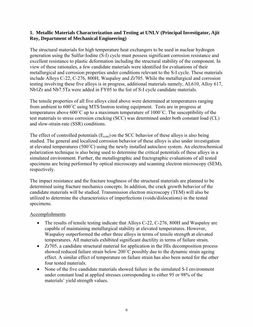
1. Metallic Materials Characterization and Testing at UNLV (Principal Investigator, Ajit Roy, Department of Mechanical Engineering) The structural materials for high temperature heat exchangers to be used in nuclear hydrogen generation using the Sulfur-Iodine (S-I) cycle must possess significant corrosion resistance and excellent resistance to plastic deformation including the structural stability of the component. In view of these rationales, a few candidate materials were identified for evaluations of their metallurgical and corrosion properties under conditions relevant to the S-I cycle. These materials include Alloys C-22, C-276, 800H, Waspaloy and Zr705. While the metallurgical and corrosion testing involving these five alloys is in progress, additional materials namely, AL610, Alloy 617, Nb1Zr and Nb7.5Ta were added in FY05 to the list of S-I cycle candidate materials. The tensile properties of all five alloys cited above were determined at temperatures ranging from ambient to 600○C using MTS/Instron testing equipment. Tests are in progress at temperatures above 600○C up to a maximum temperature of 1000○C. The susceptibility of the test materials to stress corrosion cracking (SCC) was determined under both constant load (CL) and slow-strain-rate (SSR) conditions. The effect of controlled potentials (Econt) on the SCC behavior of these alloys is also being studied. The general and localized corrosion behavior of these alloys is also under investigation at elevated temperatures (500○C) using the newly installed autoclave system. An electrochemical polarization technique is also being used to determine the critical potentials of these alloys in a simulated environment. Further, the metallographic and fractographic evaluations of all tested specimens are being performed by optical microscopy and scanning electron microscopy (SEM), respectively. The impact resistance and the fracture toughness of the structural materials are planned to be determined using fracture mechanics concepts. In addition, the crack growth behavior of the candidate materials will be studied. Transmission electron microscopy (TEM) will also be utilized to determine the characteristics of imperfections (voids/dislocations) in the tested specimens.
Accomplishments
• The results of tensile testing indicate that Alloys C-22, C-276, 800H and Waspaloy are capable of maintaining metallurgical stability at elevated temperatures. However, Waspaloy outperformed the other three alloys in terms of tensile strength at elevated temperatures. All materials exhibited significant ductility in terms of failure strain.
• Zr705, a candidate structural material for application in the HIx decomposition process showed reduced failure strain below 200○C possibly due to the dynamic strain ageing effect. A similar effect of temperature on failure strain has also been noted for the other four tested materials.
• None of the five candidate materials showed failure in the simulated S-I environment under constant load at applied stresses corresponding to either 95 or 98% of the materials’ yield strength values.
7
• The results of SSR testing in a similar solution showed a gradual reduction in true failure stress with increasing temperature. However, insignificant variations in the ductility parameters and time-to-failure (TTF) were noted in these tests.
• The results of localized corrosion studies by the cyclic potentiodynamic polarization (CPP) technique revealed more active (negative) critical potentials at elevated temperatures.
• The results of autoclave testing in a 150○C acidic solution indicate that Alloy C-276 experienced the lowest corrosion rate in terms of mils per year (mpy). The C-ring specimens of Zr705 did not exhibit cracking even after an exposure of four weeks.
• The fractographic evaluations of the tested specimens by SEM revealed dimpled microstructures indicating ductile failures.
FY 2005 Publications/Presentations 1. A. K. Roy, R. A. Karamcheti, N. Kothapalli, L. Savalia, “Metallurgical Stability and Corrosion Behavior of Structural Materials for Hydrogen Generation,” Journal of ASTM International, (In Review) 2. A. K. Roy and V. Virupaksha “High-Temperature Deformation Characteristics and Corrosion Susceptibility of Alloy 800H,” to be presented at the 2005 MRS Fall Meeting, Boston, MA, November 2005 3. A. K. Roy, A. Kaiparambil, R. Santhanakrishnan, B. Wong, G. Besenbruch and L. Brown, “Use of Refractory Materials for Hydrogen Generation using Nuclear Power,” to be presented at the 2005 MRS Fall Meeting, Boston, MA, November 2005 4. A. K. Roy and J. Pal, “Tensile Properties and Corrosion Susceptibility of C-276 in S-I Environment,” to be presented at the AIChE Conference, Cincinnati, OH, October 2005 5. A. K. Roy, R. Santhanakrishnan, A. Kaiparambil, B. Wong, G. Besenbruch and L. Brown, “Characterization of Structural Materials for Nuclear Hydrogen Generation,” to be presented at the AIChE Conference, Cincinnati, OH, October 2005 6. A. K. Roy and V. Virupaksha, “Use of Alloy 800H as a Heat-Exchanger Structural Materials,” to be presented at the AIChE Conference, Cincinnati, OH, October 2005 7. A. K. Roy, R. Santhanakrishnan, A. Kaiparambil, B. Wong, G. Besenbruch and L. Brown, “Characterization of Materials for Hydrogen Generation by HIx Decomposition,” to be presented at the SAMPE Conference, Seattle, WA, October 2005 8. A. K. Roy and V. Virupaksha, “Metallurgical and Corrosion Study of Alloy 800H,” to be presented at the SAMPE Conference, Seattle, WA, October 2005 9. A. K. Roy, R. Santhanakrishnan, A. Kaiparambil, B. Wong, G. Besenbruch and L. Brown, “Metallurgical and Corrosion Characterization of Structural Materials for the Nuclear Hydrogen Initiative,” MS&T 2005 Conference, Pittsburgh, PA, September 2005

8
10. A. K. Roy and V. Virupaksha, “Characterization of Alloy 800H for Heat Exchanger Applications,” MS&T 2005 Conference, Pittsburgh, PA, September 2005 11. A. K. Roy, R. Karamcheti, L. Savalia, and N. Kothapalli, “Tensile Properties and Corrosion Characteristics of Heat-Exchanger Materials,” SAMPE/2005, Long Beach, CA, May 2005 12. A. K. Roy, L. Savalia, N. Kothapalli, and R. Karamcheti, “High-Temperature Properties and Corrosion Behavior of Nickel-Base Alloys,” Paper No. 05430, Corrosion/2005, NACE International, Houston, TX, April 2005
9
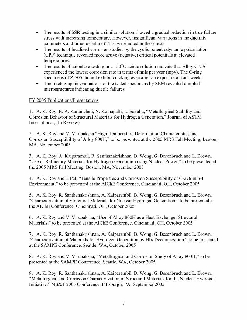
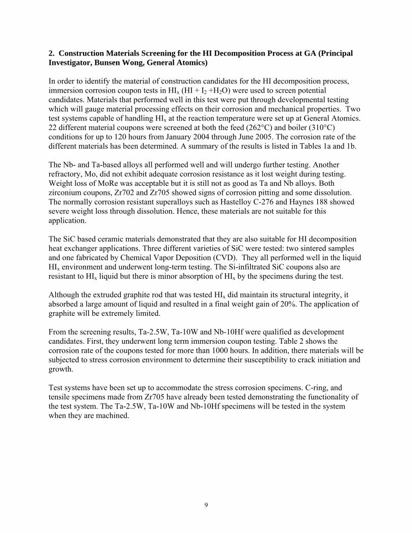
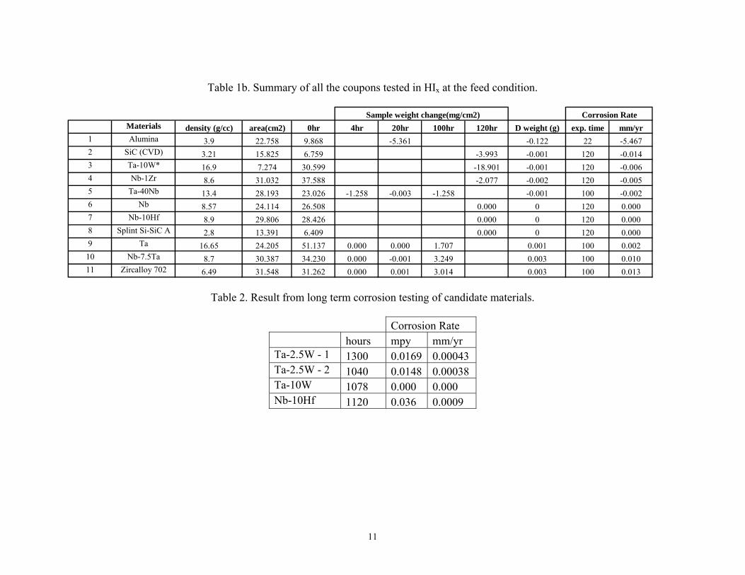
2. Construction Materials Screening for the HI Decomposition Process at GA (Principal Investigator, Bunsen Wong, General Atomics) In order to identify the material of construction candidates for the HI decomposition process, immersion corrosion coupon tests in HIx (HI + I2 +H2O) were used to screen potential candidates. Materials that performed well in this test were put through developmental testing which will gauge material processing effects on their corrosion and mechanical properties. Two test systems capable of handling HIx at the reaction temperature were set up at General Atomics. 22 different material coupons were screened at both the feed (262°C) and boiler (310°C) conditions for up to 120 hours from January 2004 through June 2005. The corrosion rate of the different materials has been determined. A summary of the results is listed in Tables 1a and 1b. The Nb- and Ta-based alloys all performed well and will undergo further testing. Another refractory, Mo, did not exhibit adequate corrosion resistance as it lost weight during testing. Weight loss of MoRe was acceptable but it is still not as good as Ta and Nb alloys. Both zirconium coupons, Zr702 and Zr705 showed signs of corrosion pitting and some dissolution. The normally corrosion resistant superalloys such as Hastelloy C-276 and Haynes 188 showed severe weight loss through dissolution. Hence, these materials are not suitable for this application. The SiC based ceramic materials demonstrated that they are also suitable for HI decomposition heat exchanger applications. Three different varieties of SiC were tested: two sintered samples and one fabricated by Chemical Vapor Deposition (CVD). They all performed well in the liquid HIx environment and underwent long-term testing. The Si-infiltrated SiC coupons also are resistant to HIx liquid but there is minor absorption of HIx by the specimens during the test. Although the extruded graphite rod that was tested HIx did maintain its structural integrity, it absorbed a large amount of liquid and resulted in a final weight gain of 20%. The application of graphite will be extremely limited. From the screening results, Ta-2.5W, Ta-10W and Nb-10Hf were qualified as development candidates. First, they underwent long term immersion coupon testing. Table 2 shows the corrosion rate of the coupons tested for more than 1000 hours. In addition, there materials will be subjected to stress corrosion environment to determine their susceptibility to crack initiation and growth. Test systems have been set up to accommodate the stress corrosion specimens. C-ring, and tensile specimens made from Zr705 have already been tested demonstrating the functionality of the test system. The Ta-2.5W, Ta-10W and Nb-10Hf specimens will be tested in the system when they are machined.

10
Table 1a. Summary of all the coupons tested in HIx at the boiler condition.
Materials density (g/cc) area(cm2) 0hr 4hr 20hr 100hr 120hr 450hr 790hr Δ weight (g) exp. time mm/yr1 Nb-1Zr 8.6 31.032 37.302 0.032 -567.217 -17.602 120 -48.09642 C-276 8.89 28.623 30.854 -335.285 -9.597 120 -27.50263 Zircalloy 702 6.49 31.548 31.312 -17.497 -17.592 -0.555 20 -11.86004 Haynes 188 8.98 28.882 32.131 -128.833 -3.721 120 -10.46205 Mo 10.3 25.753 29.285 -139.868 -3.602 120 -9.90256 Bioker 29 Si-SiC 2.7 19.320 7.581 -29.400 -0.568 120 -7.94047 Zircalloy 705 6.6 30.323 25.110 -17.479 -0.53 120 -1.93128 Mullite 3.2 20.779 7.566 -3.032 -0.063 68 -1.21939 Fiber Si-SiC 2.8 16.287 7.157 -2.701 -0.044 120 -0.7036
10 Nb-7.5Ta 8.7 30.387 34.718 -2.166 -28.158 -32.490 -0.03 100 -0.099311 Splint Si-SiC B 2.8 12.429 6.398 -0.322 -0.004 120 -0.083812 SiC (sintered) 3.1 39.444 13.318 -7.070 -0.011 120 -0.065613 Ceramatec SiC 3.1 35.500 28.954 -3.174 -0.004 120 -0.026514 Mo-47Re 13.52 22.382 6.083 -13.974 -0.007 120 -0.016915 SiC (CVD) 3.21 15.825 7.995 -3.993 -0.001 120 -0.014416 Ta 16.65 24.205 51.010 -8.534 -10.241 -10.241 -0.006 100 -0.013017 Ta-2.5W -2 16.6 26.928 11.277 0.000 0.000 330 0.00018 Ta-2.5W -1 16.6 28.279 11.829 0.035 0.001 330 0.00119 Ta-10W* 16.9 6.378 21.354 -0.157 0.314 0.157 0 1078 0.001020 Nb-10Hf 8.9 29.806 28.181 0.113 2.364 3.489 0.0031 790 0.001321 Ta-40Nb 13.4 28.193 23.488 2.516 2.516 3.774 0.003 100 0.006922 Nb 8.57 24.114 27.195 0.124 0.003 120 0.010623 graphite 2.2 13.157 5.448 129.435 1.703 120 42.9032
Corrosion Rate Sample weight change(mg/cm2)
11
Table 1b. Summary of all the coupons tested in HIx at the feed condition.
Materials density (g/cc) area(cm2) 0hr 4hr 20hr 100hr 120hr D weight (g) exp. time mm/yr1 Alumina 3.9 22.758 9.868 -5.361 -0.122 22 -5.4672 SiC (CVD) 3.21 15.825 6.759 -3.993 -0.001 120 -0.0143 Ta-10W* 16.9 7.274 30.599 -18.901 -0.001 120 -0.0064 Nb-1Zr 8.6 31.032 37.588 -2.077 -0.002 120 -0.0055 Ta-40Nb 13.4 28.193 23.026 -1.258 -0.003 -1.258 -0.001 100 -0.0026 Nb 8.57 24.114 26.508 0.000 0 120 0.0007 Nb-10Hf 8.9 29.806 28.426 0.000 0 120 0.0008 Splint Si-SiC A 2.8 13.391 6.409 0.000 0 120 0.0009 Ta 16.65 24.205 51.137 0.000 0.000 1.707 0.001 100 0.002
10 Nb-7.5Ta 8.7 30.387 34.230 0.000 -0.001 3.249 0.003 100 0.01011 Zircalloy 702 6.49 31.548 31.262 0.000 0.001 3.014 0.003 100 0.013
Corrosion Rate Sample weight change(mg/cm2)
Table 2. Result from long term corrosion testing of candidate materials.
Corrosion Rate hours mpy mm/yr Ta-2.5W - 1 1300 0.0169 0.00043 Ta-2.5W - 2 1040 0.0148 0.00038 Ta-10W 1078 0.000 0.000 Nb-10Hf 1120 0.036 0.0009
12
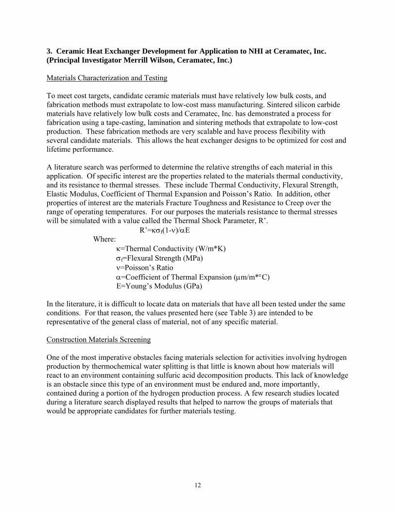
3. Ceramic Heat Exchanger Development for Application to NHI at Ceramatec, Inc. (Principal Investigator Merrill Wilson, Ceramatec, Inc.) Materials Characterization and Testing To meet cost targets, candidate ceramic materials must have relatively low bulk costs, and fabrication methods must extrapolate to low-cost mass manufacturing. Sintered silicon carbide materials have relatively low bulk costs and Ceramatec, Inc. has demonstrated a process for fabrication using a tape-casting, lamination and sintering methods that extrapolate to low-cost production. These fabrication methods are very scalable and have process flexibility with several candidate materials. This allows the heat exchanger designs to be optimized for cost and lifetime performance. A literature search was performed to determine the relative strengths of each material in this application. Of specific interest are the properties related to the materials thermal conductivity, and its resistance to thermal stresses. These include Thermal Conductivity, Flexural Strength, Elastic Modulus, Coefficient of Thermal Expansion and Poisson’s Ratio. In addition, other properties of interest are the materials Fracture Toughness and Resistance to Creep over the range of operating temperatures. For our purposes the materials resistance to thermal stresses will be simulated with a value called the Thermal Shock Parameter, R’.
R’=κσf(1-ν)/αE Where: κ=Thermal Conductivity (W/m*K) σf=Flexural Strength (MPa) ν=Poisson’s Ratio α=Coefficient of Thermal Expansion (μm/m*°C) E=Young’s Modulus (GPa) In the literature, it is difficult to locate data on materials that have all been tested under the same conditions. For that reason, the values presented here (see Table 3) are intended to be representative of the general class of material, not of any specific material. Construction Materials Screening One of the most imperative obstacles facing materials selection for activities involving hydrogen production by thermochemical water splitting is that little is known about how materials will react to an environment containing sulfuric acid decomposition products. This lack of knowledge is an obstacle since this type of an environment must be endured and, more importantly, contained during a portion of the hydrogen production process. A few research studies located during a literature search displayed results that helped to narrow the groups of materials that would be appropriate candidates for further materials testing.
13
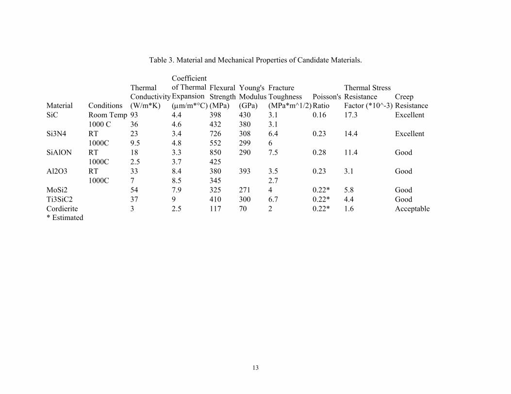
Table 3. Material and Mechanical Properties of Candidate Materials.
Material Conditions
Thermal Conductivity (W/m*K)
Coefficient of Thermal Expansion (μm/m*°C)
Flexural Strength (MPa)
Young's Modulus (GPa)
Fracture Toughness (MPa*m^1/2)
Poisson's Ratio
Thermal Stress Resistance Factor (*10^-3)
Creep Resistance
SiC Room Temp 93 4.4 398 430 3.1 0.16 17.3 Excellent 1000 C 36 4.6 432 380 3.1 Si3N4 RT 23 3.4 726 308 6.4 0.23 14.4 Excellent 1000C 9.5 4.8 552 299 6 SiAlON RT 18 3.3 850 290 7.5 0.28 11.4 Good 1000C 2.5 3.7 425 Al2O3 RT 33 8.4 380 393 3.5 0.23 3.1 Good 1000C 7 8.5 345 2.7 MoSi2 54 7.9 325 271 4 0.22* 5.8 Good Ti3SiC2 37 9 410 300 6.7 0.22* 4.4 Good Cordierite 3 2.5 117 70 2 0.22* 1.6 Acceptable* Estimated
14
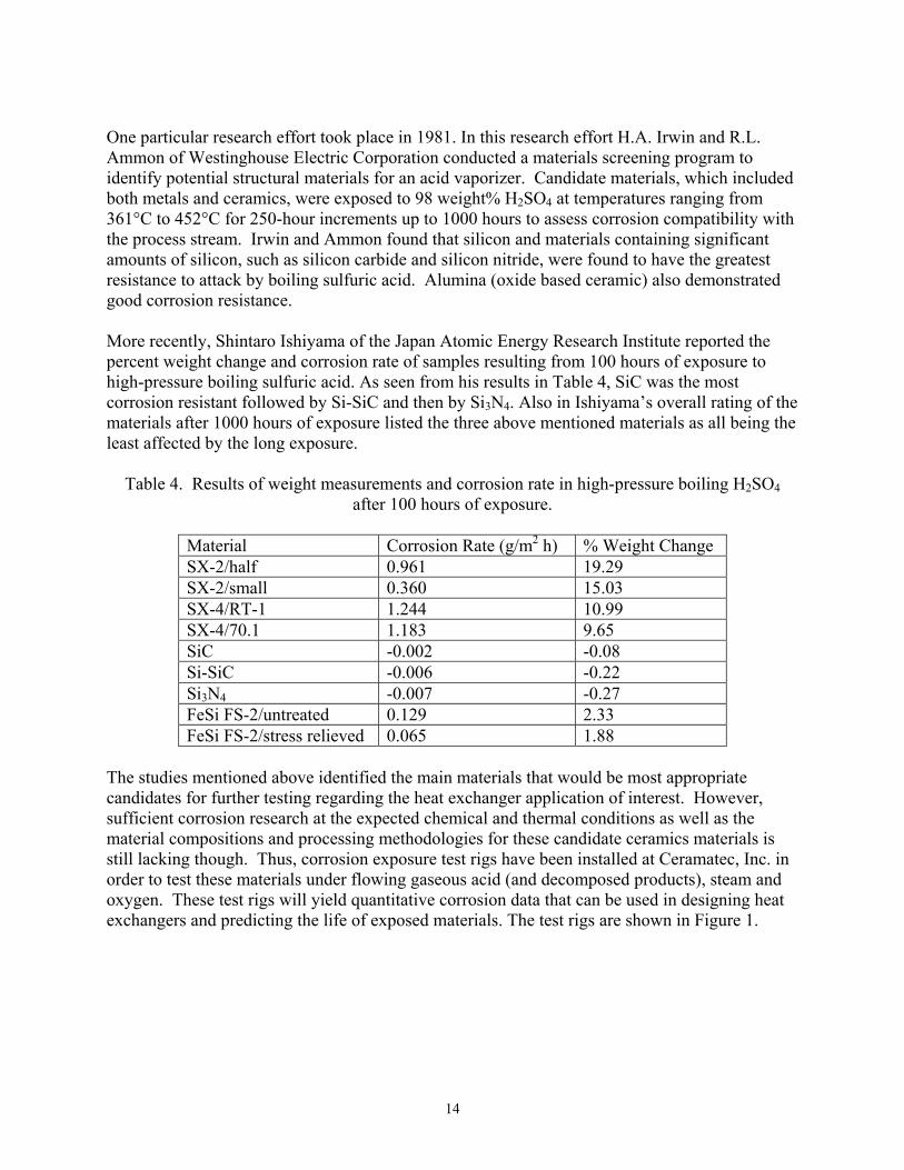
One particular research effort took place in 1981. In this research effort H.A. Irwin and R.L. Ammon of Westinghouse Electric Corporation conducted a materials screening program to identify potential structural materials for an acid vaporizer. Candidate materials, which included both metals and ceramics, were exposed to 98 weight% H2SO4 at temperatures ranging from 361°C to 452°C for 250-hour increments up to 1000 hours to assess corrosion compatibility with the process stream. Irwin and Ammon found that silicon and materials containing significant amounts of silicon, such as silicon carbide and silicon nitride, were found to have the greatest resistance to attack by boiling sulfuric acid. Alumina (oxide based ceramic) also demonstrated good corrosion resistance. More recently, Shintaro Ishiyama of the Japan Atomic Energy Research Institute reported the percent weight change and corrosion rate of samples resulting from 100 hours of exposure to high-pressure boiling sulfuric acid. As seen from his results in Table 4, SiC was the most corrosion resistant followed by Si-SiC and then by Si3N4. Also in Ishiyama’s overall rating of the materials after 1000 hours of exposure listed the three above mentioned materials as all being the least affected by the long exposure.
Table 4. Results of weight measurements and corrosion rate in high-pressure boiling H2SO4
after 100 hours of exposure.
Material Corrosion Rate (g/m2 h) % Weight Change SX-2/half 0.961 19.29 SX-2/small 0.360 15.03 SX-4/RT-1 1.244 10.99 SX-4/70.1 1.183 9.65 SiC -0.002 -0.08 Si-SiC -0.006 -0.22 Si3N4 -0.007 -0.27 FeSi FS-2/untreated 0.129 2.33 FeSi FS-2/stress relieved 0.065 1.88
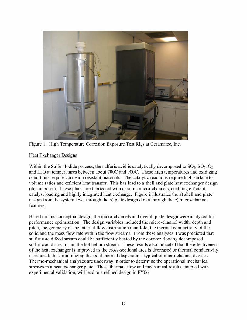
The studies mentioned above identified the main materials that would be most appropriate candidates for further testing regarding the heat exchanger application of interest. However, sufficient corrosion research at the expected chemical and thermal conditions as well as the material compositions and processing methodologies for these candidate ceramics materials is still lacking though. Thus, corrosion exposure test rigs have been installed at Ceramatec, Inc. in order to test these materials under flowing gaseous acid (and decomposed products), steam and oxygen. These test rigs will yield quantitative corrosion data that can be used in designing heat exchangers and predicting the life of exposed materials. The test rigs are shown in Figure 1.
15
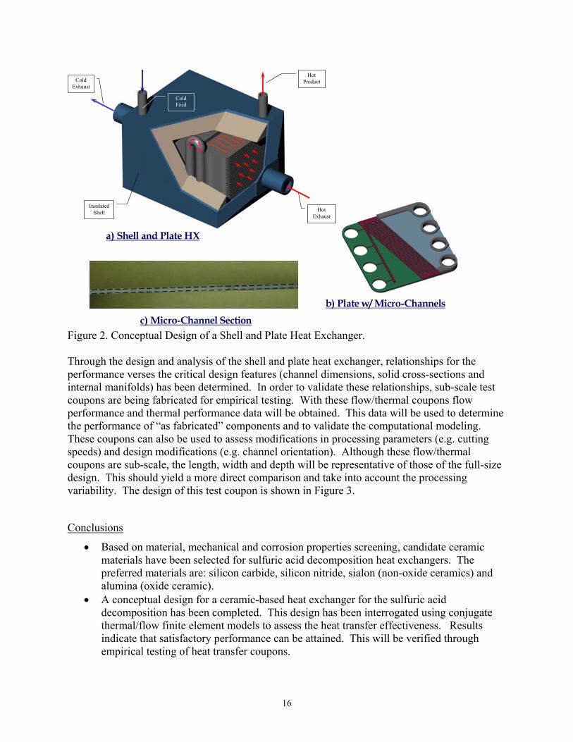
Figure 1. High Temperature Corrosion Exposure Test Rigs at Ceramatec, Inc. Heat Exchanger Designs Within the Sulfur-Iodide process, the sulfuric acid is catalytically decomposed to SO2, SO3, O2 and H2O at temperatures between about 700C and 900C. These high temperatures and oxidizing conditions require corrosion resistant materials. The catalytic reactions require high surface to volume ratios and efficient heat transfer. This has lead to a shell and plate heat exchanger design (decomposer). These plates are fabricated with ceramic micro-channels, enabling efficient catalyst loading and highly integrated heat exchange. Figure 2 illustrates the a) shell and plate design from the system level through the b) plate design down through the c) micro-channel features. Based on this conceptual design, the micro-channels and overall plate design were analyzed for performance optimization. The design variables included the micro-channel width, depth and pitch, the geometry of the internal flow distribution manifold, the thermal conductivity of the solid and the mass flow rate within the flow streams. From these analyses it was predicted that sulfuric acid feed stream could be sufficiently heated by the counter-flowing decomposed sulfuric acid stream and the hot helium stream. These results also indicated that the effectiveness of the heat exchanger is improved as the cross-sectional area is decreased or thermal conductivity is reduced; thus, minimizing the axial thermal dispersion – typical of micro-channel devices. Thermo-mechanical analyses are underway in order to determine the operational mechanical stresses in a heat exchanger plate. These thermal, flow and mechanical results, coupled with experimental validation, will lead to a refined design in FY06.
16
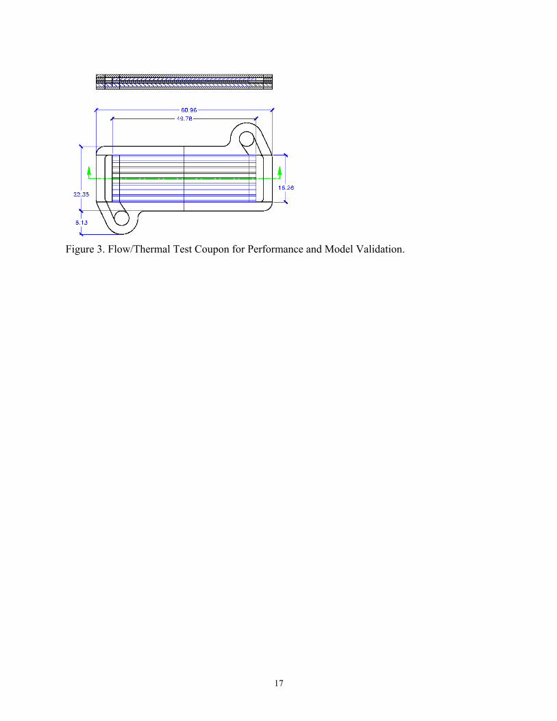
Figure 2. Conceptual Design of a Shell and Plate Heat Exchanger. Through the design and analysis of the shell and plate heat exchanger, relationships for the performance verses the critical design features (channel dimensions, solid cross-sections and internal manifolds) has been determined. In order to validate these relationships, sub-scale test coupons are being fabricated for empirical testing. With these flow/thermal coupons flow performance and thermal performance data will be obtained. This data will be used to determine the performance of “as fabricated” components and to validate the computational modeling. These coupons can also be used to assess modifications in processing parameters (e.g. cutting speeds) and design modifications (e.g. channel orientation). Although these flow/thermal coupons are sub-scale, the length, width and depth will be representative of those of the full-size design. This should yield a more direct comparison and take into account the processing variability. The design of this test coupon is shown in Figure 3.
Conclusions
• Based on material, mechanical and corrosion properties screening, candidate ceramic materials have been selected for sulfuric acid decomposition heat exchangers. The preferred materials are: silicon carbide, silicon nitride, sialon (non-oxide ceramics) and alumina (oxide ceramic).
• A conceptual design for a ceramic-based heat exchanger for the sulfuric acid decomposition has been completed. This design has been interrogated using conjugate thermal/flow finite element models to assess the heat transfer effectiveness. Results indicate that satisfactory performance can be attained. This will be verified through empirical testing of heat transfer coupons.
a) Shell and Plate HX
b) Plate w/ Micro-Channels
Cold Exhaust
Cold Feed
Hot Product
Hot Exhaust
Insulated Shell
c) Micro-Channel Section
17
Figure 3. Flow/Thermal Test Coupon for Performance and Model Validation.
18
4. Materials, design, and modeling for C/SiC ceramic heat exchangers at UC Berkeley (Principal Investigator Per Peterson, Nuclear Engineering Department) To meet cost targets, candidate ceramic materials must have relatively low bulk costs, and fabrication methods must extrapolate to low-cost mass manufacturing. Researchers at the University of California, Berkeley surveyed candidate heat exchanger materials and fabrication methods, with a focus on low-cost chopped-carbon fiber reinforced silicon carbide, where the silicon carbide is infiltrated by either melt (MI) or polymer infiltration and pyrolysis, and where additional low-cost filler materials may be used. Research conducted at UC Berkeley focused on inexpensive chopped carbon fiber based ceramic composite. Helium permeation testing and mechanical property testing were conducted. Young’s moduli of carbon fiber reinforced SiSiC (FR-SiSiC), splint based SiSiC (SB-SiSiC) and pitch based carbon fiber reinforced SiSiC (BioKer) were tested by using a strain gauge. The material properties and measured values are given in Table 5.
Table 5. Properties of Melt Infiltration Materials.
MI Material Density kg/m3
Young’s modulus GPa
Failure stress MPa
Carbon fiber reinforced SiSiC with coating
2523 325 270
Splint based SiSiC 2932 450 224 Pitch based SiSiC 2600 298 200 Short fiber reinforced SiC 2000 60 90 - 140
In collaboration with ceramic vendor COI, methods to make heat exchanger plates from chopped carbon fiber reinforced SiC composite material with PIP process were surveyed. UCB finished the design of molds and fabricated the graphite molds. Experimental tries are being performed with die embossed methods. Heat Exchanger Designs Mechanical and initial thermal stress analyses were completed for an offset strip-fin hybrid plate type compact ceramic heat exchanger by UCB. The heat exchanger is made from liquid silicon impregnated carbon composite. The study was conducted with helium gas and molten salt as the working fluids with varied channel dimensions. Thermal and stress analysis were performed to identify optimal designs for core heat transfer unit, inlet and outlet manifolds, distribution channels, and channel dividers. Finding detailed stress distribution in a complete heat exchanger with direct FEM (Finite Element Method) requires an order of a billion FEM computation units and millions of hours computing time. Therefore, it is not practical to analyze the entire heat exchanger design directly. UCB proposes an alternative method to obtain approximate stresses that only requires several days to finish in a fast computer. The methods are composed of three steps. First, the heat exchanger is broken down into several regions. Unit cell models are built
19
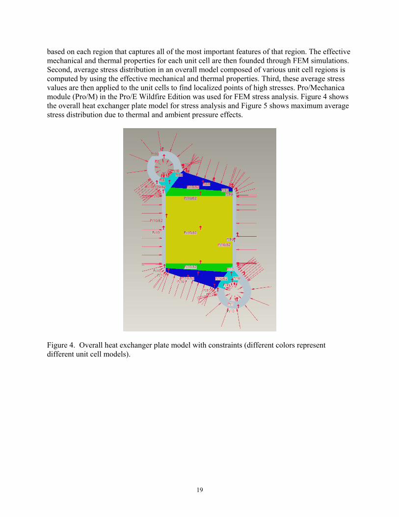
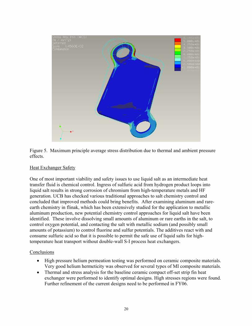
based on each region that captures all of the most important features of that region. The effective mechanical and thermal properties for each unit cell are then founded through FEM simulations. Second, average stress distribution in an overall model composed of various unit cell regions is computed by using the effective mechanical and thermal properties. Third, these average stress values are then applied to the unit cells to find localized points of high stresses. Pro/Mechanica module (Pro/M) in the Pro/E Wildfire Edition was used for FEM stress analysis. Figure 4 shows the overall heat exchanger plate model for stress analysis and Figure 5 shows maximum average stress distribution due to thermal and ambient pressure effects.
Figure 4. Overall heat exchanger plate model with constraints (different colors represent different unit cell models).
20
Figure 5. Maximum principle average stress distribution due to thermal and ambient pressure effects. Heat Exchanger Safety One of most important viability and safety issues to use liquid salt as an intermediate heat transfer fluid is chemical control. Ingress of sulfuric acid from hydrogen product loops into liquid salt results in strong corrosion of chromium from high-temperature metals and HF generation. UCB has checked various traditional approaches to salt chemistry control and concluded that improved methods could bring benefits. After examining aluminum and rare-earth chemistry in flinak, which has been extensively studied for the application to metallic aluminum production, new potential chemistry control approaches for liquid salt have been identified. These involve dissolving small amounts of aluminum or rare earths in the salt, to control oxygen potential, and contacting the salt with metallic sodium (and possibly small amounts of potassium) to control fluorine and sulfur potentials. The additives react with and consume sulfuric acid so that it is possible to permit the safe use of liquid salts for high-temperature heat transport without double-wall S-I process heat exchangers.
Conclusions
• High pressure helium permeation testing was performed on ceramic composite materials. Very good helium hermeticity was observed for several types of MI composite materials.
• Thermal and stress analysis for the baseline ceramic compact off-set strip fin heat exchanger were performed to identify optimal designs. High stresses regions were found. Further refinement of the current designs need to be performed in FY06.

21
• It is possible to safely use liquid salts for high-temperature heat transport without double-wall S-I process heat exchangers with proper chemical control.
FY 2005 Publications/Presentations B. Laurenty, G. Fukuda, D. Damba, and P. Peterson, “Inhibiting Corrosion By Molten Fluoride Salts: Investigations On Flinak,” AIChE, October, 2005, Cincinnati, OH.
22
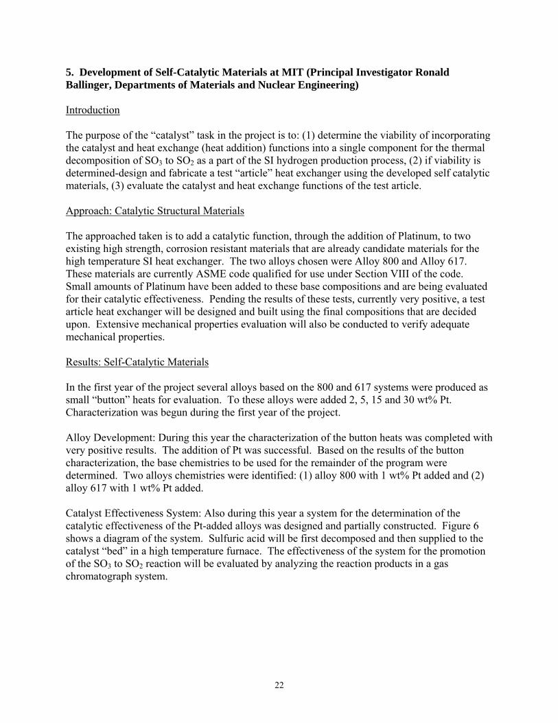
5. Development of Self-Catalytic Materials at MIT (Principal Investigator Ronald Ballinger, Departments of Materials and Nuclear Engineering) Introduction The purpose of the “catalyst” task in the project is to: (1) determine the viability of incorporating the catalyst and heat exchange (heat addition) functions into a single component for the thermal decomposition of SO3 to SO2 as a part of the SI hydrogen production process, (2) if viability is determined-design and fabricate a test “article” heat exchanger using the developed self catalytic materials, (3) evaluate the catalyst and heat exchange functions of the test article. Approach: Catalytic Structural Materials The approached taken is to add a catalytic function, through the addition of Platinum, to two existing high strength, corrosion resistant materials that are already candidate materials for the high temperature SI heat exchanger. The two alloys chosen were Alloy 800 and Alloy 617. These materials are currently ASME code qualified for use under Section VIII of the code. Small amounts of Platinum have been added to these base compositions and are being evaluated for their catalytic effectiveness. Pending the results of these tests, currently very positive, a test article heat exchanger will be designed and built using the final compositions that are decided upon. Extensive mechanical properties evaluation will also be conducted to verify adequate mechanical properties. Results: Self-Catalytic Materials In the first year of the project several alloys based on the 800 and 617 systems were produced as small “button” heats for evaluation. To these alloys were added 2, 5, 15 and 30 wt% Pt. Characterization was begun during the first year of the project. Alloy Development: During this year the characterization of the button heats was completed with very positive results. The addition of Pt was successful. Based on the results of the button characterization, the base chemistries to be used for the remainder of the program were determined. Two alloys chemistries were identified: (1) alloy 800 with 1 wt% Pt added and (2) alloy 617 with 1 wt% Pt added. Catalyst Effectiveness System: Also during this year a system for the determination of the catalytic effectiveness of the Pt-added alloys was designed and partially constructed. Figure 6 shows a diagram of the system. Sulfuric acid will be first decomposed and then supplied to the catalyst “bed” in a high temperature furnace. The effectiveness of the system for the promotion of the SO3 to SO2 reaction will be evaluated by analyzing the reaction products in a gas chromatograph system.
23
Figure 6. Catalyst effectiveness system diagram. Compact Heat Exchanger Design: During this year a preliminary design for the compact heat exchanger was completed. The final design will be determined in FY06. The current design choice is between a “compact” plate-fin design and a printed circuit design. The final design will be determined based on discussions between the vendor (HEATRIC), UNLV, and Sandia National Laboratory scientists. The design must be able to fit into the existing testing facilities for the program. MIT and Sandia National Laboratory have (or will have) testing facilities for catalytic effectiveness (MIT) and full heat exchanger effectiveness (Sandia). The thermal hydraulic design and chemistry modeling of the heat exchanger will be performed at UNLV.
75% H2SO4
MeteringPump
High Purity Helium
Mass Flow Meter/Controller
Collection Flasks to remove SO3
and liquidSO3 is converted to SO2 in the presence of the catalyst and
heat
Bypass Valve
900°C Furnace
500°C Furnace
High Purity HeliumFor Calibration
Gas Chromatograph
He + H2SO4 + heat -> He + H20 + SO3
Platinum mesh catalyzes
conversion of SO2 to SO3
SO3 is converted
back to H2SO4 by bubbling
through water
24
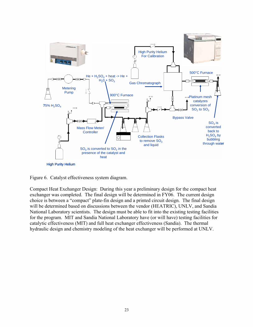
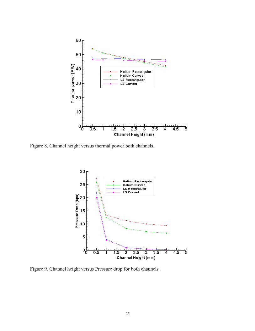
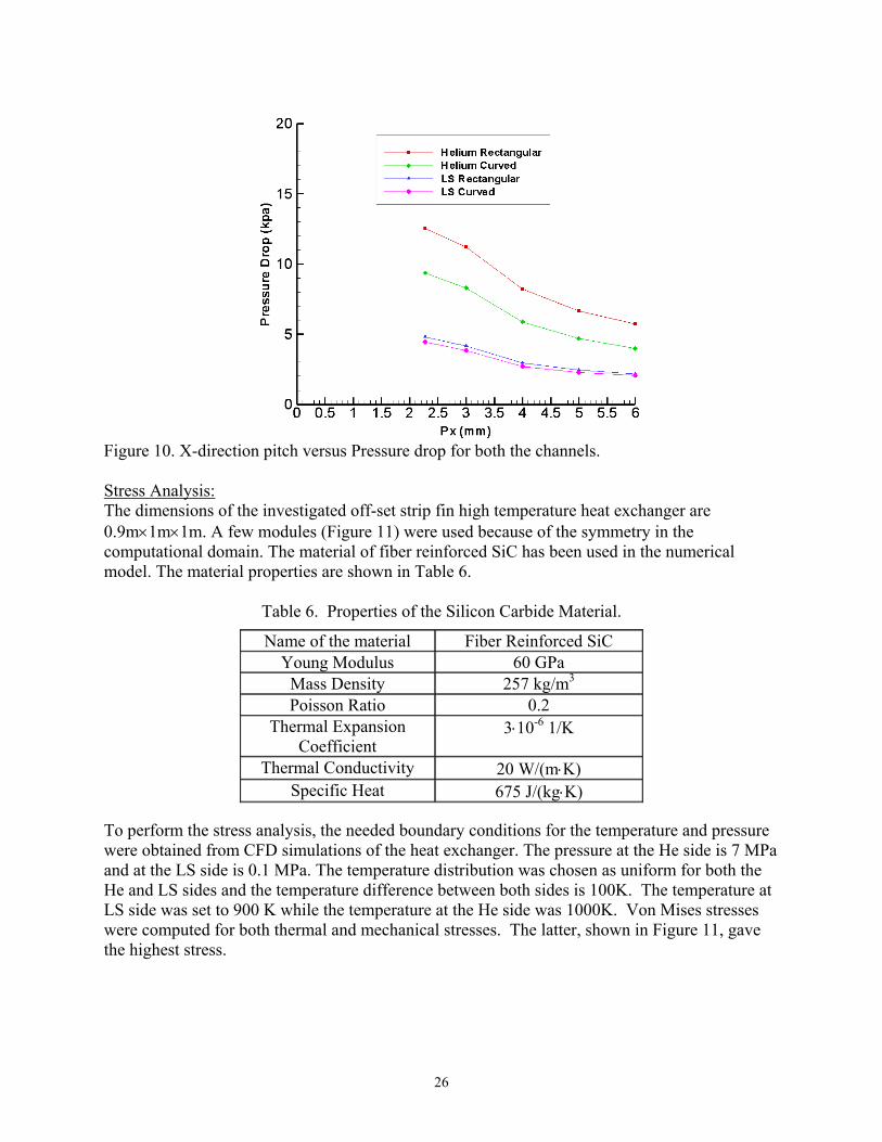
6. Heat Exchanger Design at UNLV (Principal Investigator Yitung Chen, Mechanical Engineering Department) Design of Offset Strip Fin The investigations on the effect of manufacturing on the geometry (such as fillets) and optimization studies for the offset strip fin heat exchanger design have been accomplished to study the effect of channel geometry on the pressure drop and thermal performance. The study was conducted with helium gas and liquid salt (LS) as the working fluids with varied channel dimensions. The analyses were performed for both curved and rectangular fin edge channel designs using an incompressible fluid flow model, constant physical properties, and k-omega turbulence model for the helium side wherever necessary. Design Including Manufacturing Geometrical Effects: For the turbulent case the influence of the fillets is very strong for the pressure drop on the LS side (17%) and He side (26%). But the influence is almost negligible (less than 3%) for the thermal performance. Optimization Studies: The baseline design parameters are kept as the reference values, and the values of the changed parameters were varied below and above the baseline parameter values for optimization studies. The studies were also performed in such a way that for all designs the overall dimensions such as the length, width, and the height are almost the same. Since these studies would require a lot of computational time all the simulations were carried out using a reduced overall length. The fin thickness, gap-length (Figure 7), and fin length values influenced the pressure drop performance very significantly, but were insignificant on their effect on thermal performance. The effects of varying channel heights (Figures 8 and 9) and pitch in x-direction (Figure 10) were very significant on both the pressure drop and thermal performance.
Figure 7. Gap length vs Pressure drop for both channels.
25
Figure 8. Channel height versus thermal power both channels.
Figure 9. Channel height versus Pressure drop for both channels.
26
Figure 10. X-direction pitch versus Pressure drop for both the channels. Stress Analysis: The dimensions of the investigated off-set strip fin high temperature heat exchanger are 0.9m×1m×1m. A few modules (Figure 11) were used because of the symmetry in the computational domain. The material of fiber reinforced SiC has been used in the numerical model. The material properties are shown in Table 6.
Table 6. Properties of the Silicon Carbide Material.
To perform the stress analysis, the needed boundary conditions for the temperature and pressure were obtained from CFD simulations of the heat exchanger. The pressure at the He side is 7 MPa and at the LS side is 0.1 MPa. The temperature distribution was chosen as uniform for both the He and LS sides and the temperature difference between both sides is 100K. The temperature at LS side was set to 900 K while the temperature at the He side was 1000K. Von Mises stresses were computed for both thermal and mechanical stresses. The latter, shown in Figure 11, gave the highest stress.
Name of the material Fiber Reinforced SiC Young Modulus 60 GPa
Mass Density 257 kg/m3 Poisson Ratio 0.2
Thermal Expansion Coefficient
3⋅10-6 1/K
Thermal Conductivity 20 W/(m⋅K) Specific Heat 675 J/(kg⋅K)

27
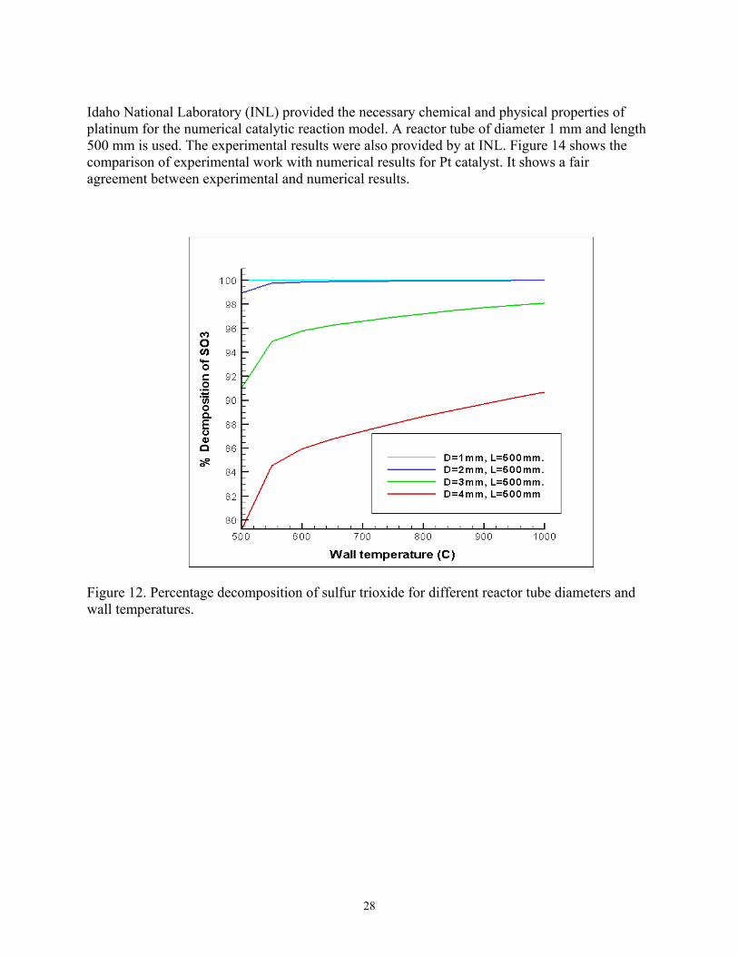
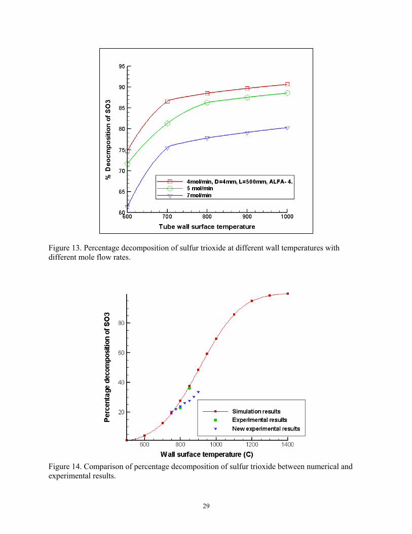
Figure 11. Von Mises mechanical stresses (Pa). Analysis of Sulfur Trioxide Decomposition Heat Exchanger A cross-flow type of heat exchanger was chosen for the analysis of the decomposition of sulfur trioxide. Initial work has been carried out on a single reactor tube to study the different parameters affecting the decomposition of sulfur trioxide. A reactor tubes have a 12.7 mm diameter and 500 mm length. The computational mesh was created using GAMBIT 2.1 and numerical simulation was performed using FLUENT 6.2 on a two-dimensional numerical model after applying proper boundary conditions. Catalyst ALFA-4 properties were used instead of platinum because of unavailability of data related to platinum. Different simulation cases are studied to find the variation of decomposition of sulfur trioxide with the wall surface temperatures. It was observed that the percentage decomposition of sulfur trioxide is increasing with the increase of tube wall surface temperature. But the decomposition of sulfur trioxide is very low even at higher temperatures because there is a very high percentage of undecomposed sulfur trioxide remaining at the center of the reactor tube. The smaller diameter reactor tube would provide higher decomposition rates because of increased surface area at a specific given mass flow rate. A total of 44 numerical cases were run from 500 to 1000oC with an interval of 50oC to study the variation in the percentage decomposition of sulfur trioxide for different reactor tube diameters and wall surface temperatures. The diameters selected for the analyses are 1, 2, 3 and 4 mm and the length of the reactor tube is kept constant at 500 mm. The results are shown in Figure 12. The decomposition of sulfur trioxide varies with the mole flow rate. The different simulation cases were also studied for the different mole flow rates of the sulfuric acid in the decomposer. The numerical results are shown in Figure 13.
28
Idaho National Laboratory (INL) provided the necessary chemical and physical properties of platinum for the numerical catalytic reaction model. A reactor tube of diameter 1 mm and length 500 mm is used. The experimental results were also provided by at INL. Figure 14 shows the comparison of experimental work with numerical results for Pt catalyst. It shows a fair agreement between experimental and numerical results.
Figure 12. Percentage decomposition of sulfur trioxide for different reactor tube diameters and wall temperatures.
29
Figure 13. Percentage decomposition of sulfur trioxide at different wall temperatures with different mole flow rates.
Figure 14. Comparison of percentage decomposition of sulfur trioxide between numerical and experimental results.
30
Conclusions
• Optimization studies and the effect of fillets using computational fluid dynamics (CFD) techniques for pressure drop and thermal performance were accomplished for ceramic compact off-set strip fin high temperature heat exchanger.
• Mechanical stresses are much larger than thermal stresses (approximately 5 to 7 times). Therefore, the thermal stresses can be neglected compared to the mechanical stresses.
• The maximum value of Von Mises stress for the SiC material is higher than failure stress for the material (90-140 MPa). Therefore, the Fiber Reinforced SiC may not be an appropriate material for the heat exchanger with the selected operating conditions.
• The decomposition rates of sulfur trioxide are very low at temperatures below 700oC. • The decomposition rate of sulfur trioxide is better for the smaller diameter reactor tubes.
The pressure drop is still in the favorable range based on the study of the reactor tube of diameter 1 mm and length 500 mm.
• Frequent intermixing of sulfur trioxide could lead to very high decomposition rates.
FY 2005 Publications/Presentations 1. S. Subramanian, V Ponyavin, C.R. DeLosier, Y.T. Chen, A.E. Hechanova and P.F. Peterson, “The Effect of Fin Geometry on design of Compact Offset Strip-Fin High Temperature Heat Exchanger,” Proceedings of the ASME International Mechanical Engineering Congress and Exposition 2005, Orlando, FL, November 2005 2. V. Ponyavin, S. Subramanian, C.R. DeLosier, Y.T. Chen, A.E. Hechanova and P.F. Peterson, “Stress Analysis of an High temperature Heat Exchanger Used in an Advanced Nuclear Reactor,” Proceedings of the ASME International Mechanical Engineering Congress and Exposition 2005, Orlando, FL, November 2005 3. K.K. Muramalla, Y.T. Chen and A.E. Hechanova, “Simulation and Optimization of Homogeneous Decomposition of Sulfur Trioxide Gas on a Catalytic Surface,” Proceedings of the ASME International Mechanical Engineering Congress and Exposition 2005, Orlando, FL, November 2005 4. K.K. Muramalla, Y.T. Chen and A.E. Hechanova, “Simulation of Decomposition of Sulfur Trioxide Gas on Self-Catalytic Metallic Material,” AIChE Annual Meeting 2005, Cincinnati Convention Center, Cincinnati, OH, October 30 - November 4, 2005 5. S. Subramanian, V. Ponyavin, C.R. DeLosier, Y.T. Chen and A.E. Hechanova, “Design Considerations for Compact Ceramic Offset Strip-Fin High Temperature Heat Exchangers,” Proceeding of the Fifth international Conference of Enhanced Compact and Ultra-Compact Heat Exchangers: Science, Engineering and Technology, Whistler, British Columbia, Canada, September 2005 6. V. Ponyavin, S. Subramanian, C.R. DeLosier, Y.T. Chen, A.E. Hechanova and P.F. Peterson, “Flow Calculations in High Temperature Heat Exchanger with Manufacturing Geometrical

31
Effects,” Proceedings of the HT-2005 ASME Summer Heat Transfer Conference 2005, San Francisco, CA, July 2005 7. S. Subramanian, V. Ponyavin, C.R. DeLosier, Y.T. Chen, A.E. Hechanova and P.F. Peterson, “Design Considerations for Compact Ceramic Offset Strip-Fin High Temperature Heat Exchangers,” Proceedings of the GT2005 ASME Turbo Expo 2005, Reno, NV, June 2005 8. S. Subramanian and C.R. DeLosier, “CFD Simulation of an Offset Strip-Fin Heat exchanger,” ANS Students Conference 2005, Columbus, OH, April 2005 9. K.K. Muramalla, “Simulation of Homogeneous Decomposition of Sulfur Trioxide Gas in a Wall Catalyzed Reactor Tube,” ANS Students Conference 2005, Columbus, OH, April 2005
32
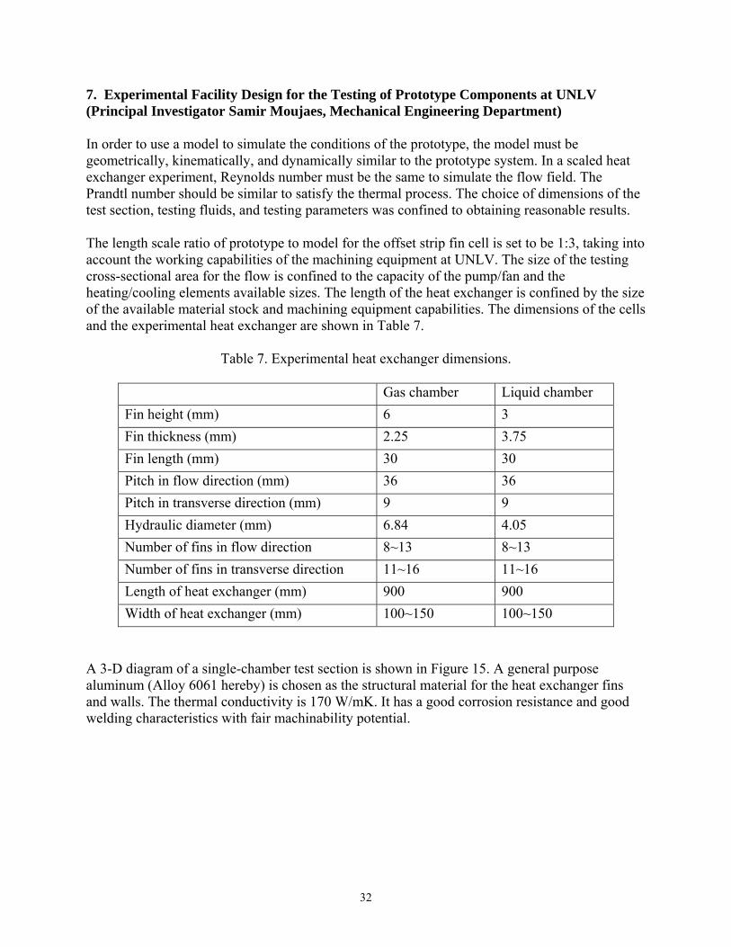
7. Experimental Facility Design for the Testing of Prototype Components at UNLV (Principal Investigator Samir Moujaes, Mechanical Engineering Department) In order to use a model to simulate the conditions of the prototype, the model must be geometrically, kinematically, and dynamically similar to the prototype system. In a scaled heat exchanger experiment, Reynolds number must be the same to simulate the flow field. The Prandtl number should be similar to satisfy the thermal process. The choice of dimensions of the test section, testing fluids, and testing parameters was confined to obtaining reasonable results. The length scale ratio of prototype to model for the offset strip fin cell is set to be 1:3, taking into account the working capabilities of the machining equipment at UNLV. The size of the testing cross-sectional area for the flow is confined to the capacity of the pump/fan and the heating/cooling elements available sizes. The length of the heat exchanger is confined by the size of the available material stock and machining equipment capabilities. The dimensions of the cells and the experimental heat exchanger are shown in Table 7.
Table 7. Experimental heat exchanger dimensions.
Gas chamber Liquid chamber Fin height (mm) 6 3 Fin thickness (mm) 2.25 3.75 Fin length (mm) 30 30 Pitch in flow direction (mm) 36 36 Pitch in transverse direction (mm) 9 9 Hydraulic diameter (mm) 6.84 4.05 Number of fins in flow direction 8~13 8~13 Number of fins in transverse direction 11~16 11~16 Length of heat exchanger (mm) 900 900 Width of heat exchanger (mm) 100~150 100~150
A 3-D diagram of a single-chamber test section is shown in Figure 15. A general purpose aluminum (Alloy 6061 hereby) is chosen as the structural material for the heat exchanger fins and walls. The thermal conductivity is 170 W/mK. It has a good corrosion resistance and good welding characteristics with fair machinability potential.

33
Figure 15. Schematic Diagram of a Single-Chamber Test Section for the Off-set Strip Fin Plate Type Heat Exchanger. A 100 mm long honeycomb straightener, shown in Figure 15, is used to provide uniform flow. There is a blank section between the honeycomb straightener and the testing fin area. For the low Reynolds number laminar liquid flow, the blank section generates fully developed flow before the liquid enters the offset strip fins. The upstream flow section has little effect on the gas flow since the Reynolds number is in a laminar region or close to the transitional region. There are thermocouples embedded in the top and bottom walls to measure the temperature distribution. There are thermocouples periodically inside the chamber to measure the fluid temperature. Differential pressure transducer taps are located before and after the offset strip fins area to measure pressure drops. The heating pad/hot fluid should be on the top to avoid natural convection. For the single-chamber liquid setup, the electrical heating pad which generates uniform heat flux is applied on the top wall. For the single-chamber gas test section, the heating pad can be applied either on the top wall, or on the bottom wall, or on both walls because the Rayleigh number is small. For the double-chamber test section, the hot fluid will flow through the top chamber, while the cold fluid will flow through the bottom chamber. Alloy 6061 tubing is used to transfer the liquid. Nylon piping is used to transfer the gas. A cooling coil made of copper tubing is immersed in a refrigerated bath and is used to cool the fluids. A heating coil made of copper tubing uses an oven to heat the fluid for the double-chamber setup. Testing Fluids Helium will be the best choice for testing on the gas because of its high specific heat capacity. Helium satisfies the ideal gas law and correlations of A Helium cylinder with a two-stage gauge works as the reservoir. Room air can also be considered to be a testing gas because it will largely simplify the system by eliminating the cooling element as it can be used in a once through system setup.
34
Dow Corning 200 Fluid, 5.0 cSt Silicone oil is chosen as a testing liquid, although its Prandtl number is higher than molten salts envisioned for the final application. Distilled-deionized water is considered as a testing liquid because of its well known properties. The Prandtl number of water has the same order of Prandtl number of molten salts. Heating and Cooling Elements Etched foil heaters are used to generate uniform heat flux for the single-chamber setup. It is rated for 120 V with 10 W/in². They will be applied on the outside of the heat exchanger walls. A 0~140 V variable transformer is used to vary the voltage in order to vary the heat flux generated by the etched foil heat. An Agilent 34401A multimeter will be used to measure the voltage. A 300 °C mechanical convection oven will be required to heat the fluid for the double-chamber setup. A refrigerated bath (cooling capacity of 2850 W at 20°C) will be used to cool the fluid after it has been heated in the chamber. Data Acquisition System and Measurement LabView data acquisition system will be used to record the pressure, temperature, and flow rate data. A relay system is used to shut down the system when the pressure is built up above safe limits and or/and the heater temperature reaches above a high predetermined temperature. Temperature: Copper-Constantan thermocouples (T type, accuracy of 0.5°C or 0.4% above 0°C) are used to measure the fluid inlet and outlet temperatures, the temperature distribution along the heat exchanger, the fluids temperature after the cooling or heating element, and the heating pad temperature for the relay. Pressure: Differential pressure transducers are used to measure the pressure drop across the fin area. The accuracy is ± 0.25% FS and 1% FS/100F. Flow rate: A vortex flowmeter (flow range of 12 to 163 m3/hr) is used to measure the gas flow rate. The accuracy is ±1% of reading. A gear flowmeter (flow range 0.01 to 2 GPM) is used to measure the liquid flow rate. The accuracy is ±0.5% of reading. Insulation The testing heat exchanger needs to be well insulated to minimize the heat loss. A layer of 3-4 cm thick fiber glass of k=0.04 W/mK is wrapped all around the test section. Experimental Testing Design The main purpose of this experimental apparatus is to test the heat transfer coefficient for the heat exchanger and friction coefficient for the pressure drop. With different dimensions and Reynolds numbers for the testing fluids, the testing runs are either a single-chamber setup with one fluid or a double-chamber with different cold and hot fluids flow through separate chambers.
35
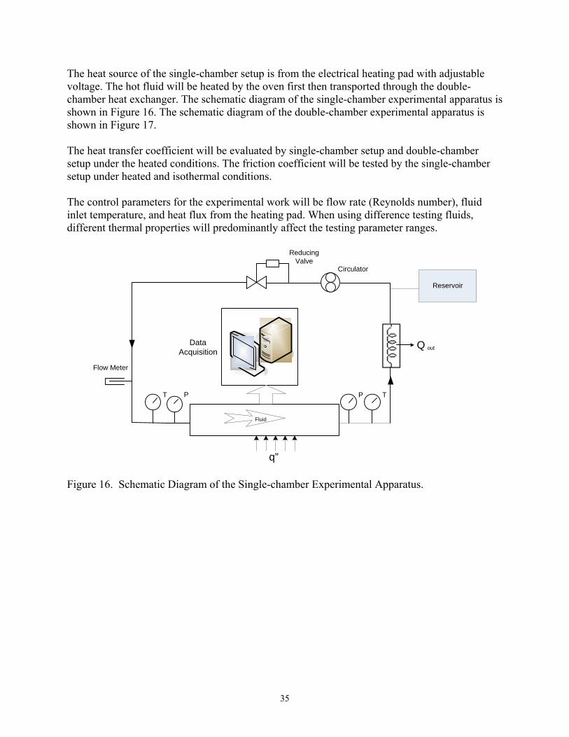
The heat source of the single-chamber setup is from the electrical heating pad with adjustable voltage. The hot fluid will be heated by the oven first then transported through the double-chamber heat exchanger. The schematic diagram of the single-chamber experimental apparatus is shown in Figure 16. The schematic diagram of the double-chamber experimental apparatus is shown in Figure 17. The heat transfer coefficient will be evaluated by single-chamber setup and double-chamber setup under the heated conditions. The friction coefficient will be tested by the single-chamber setup under heated and isothermal conditions. The control parameters for the experimental work will be flow rate (Reynolds number), fluid inlet temperature, and heat flux from the heating pad. When using difference testing fluids, different thermal properties will predominantly affect the testing parameter ranges.
Fluid
Data Acquisition
Q out
T P TP
Circulator
Flow Meter
ReducingValve
q”
Reservoir
Figure 16. Schematic Diagram of the Single-chamber Experimental Apparatus.

36
Figure 17. Schematic Diagram of the Double-chamber Experimental Apparatus. The tests will be run in the low Reynolds number range for the laminar liquid flow. For the gas flow, the tests will be run from high laminar Reynolds number to transitional Reynolds number. The Reynolds number is mainly determined by the flow rate, which is also affected through the fluid temperature by viscosity/Reynolds number. The inlet temperature of fluid is determined by the ability and efficiency of the heating or cooling element to transfer heat to/from the fluid after it leaves the testing chamber i.e. heat exchanger performance. Thermal Property Tests: The solid structure materials properties, density, specific heat, and thermal conductivity, can be tested precisely without difficulties in commercial labs up to 1000°C for the maximum working conditions. Because the molten salts are transparent and corrosive at the working temperature range (550-970°C), the reliability of thermal diffusivity test using the Laser Flash Method and thermal conductivity calculation in commercial labs needs more attention. The density and viscosity can only be tested in labs with very specific techniques.
Qout
Cold
Data Acquisition
Hot
P P
Qin
Heating
Cooling
T P TP
T T
Circulator
Circulator
Flow Meter
Flow Meter
ReducingValve
ReducingValve
Reservior
Reservior
37
Acronyms AIChE American Institute of Chemical Engineers ANS American Nuclear Society ASME American Society of Mechanical Engineering ASTM American Society for Testing and Materials CFD Computational Fluid Dynamics CL Constant Load CPP Cyclic Potentiodynamic Polarization CVD Chemical Vapor Deposition DOE U.S. Department of Energy FEM Finite Element Method FY Fiscal Year HIx HI + I2 +H2O HTHX High Temperature Heat Exchangers INL Idaho National Laboratory LS Liquid Salt MI Melt Infiltration MIT Massachusetts Institute of Technology MRS Materials Research Society MS&T Material Science and Technology MTS Materials Testing System NACE National Association of Corrosion Engineers NHI Nuclear Hydrogen Initiative PIP Polymer Infiltration and Pyrolysis SAMPE Society for the Advancement of Material and Process Engineering SCC Stress Corrosion Cracking SEM Scanning Electron Microscopy S-I Sulfur Iodine SSR Slow-Strain-Rate TEM Transmission Electron Microscopy TTF Time-To-Failure UCB University of California, Berkeley UNLV University of Nevada Las Vegas UNLVRF UNLV Research Foundation
Figure Captions Figure 1. High Temperature Corrosion Exposure Test Rigs at Ceramatec, Inc. Figure 2. Conceptual Design of a Shell and Plate Heat Exchanger. Figure 3. Flow/Thermal Test Coupon for Performance and Model Validation. Figure 4. Overall heat exchanger plate model with constraints (different colors represent different unit cell models). Figure 5. Maximum principle average stress distribution due to thermal and ambient pressure effects. Figure 6. Catalyst effectiveness system diagram. Figure 7. Gap length vs Pressure drop for both channels.
38
Figure 8. Channel height versus thermal power both channels. Figure 9. Channel height versus Pressure drop for both channels. Figure 10. X-direction pitch versus Pressure drop for both the channels. Figure 11. Von Mises mechanical stresses (Pa). Figure 12. Percentage decomposition of sulfur trioxide for different reactor tube diameters and wall temperatures. Figure 13. Percentage decomposition of sulfur trioxide at different wall temperatures with different mole flow rates. Figure 14. Comparison of percentage decomposition of sulfur trioxide between numerical and experimental results. Figure 15. Schematic Diagram of a Single-Chamber Test Section for the Off-set Strip Fin Plate Type Heat Exchanger. Figure 16. Schematic Diagram of the Single-chamber Experimental Apparatus. Figure 17. Schematic Diagram of the Double-chamber Experimental Apparatus.