Embed Size (px)
Citation preview
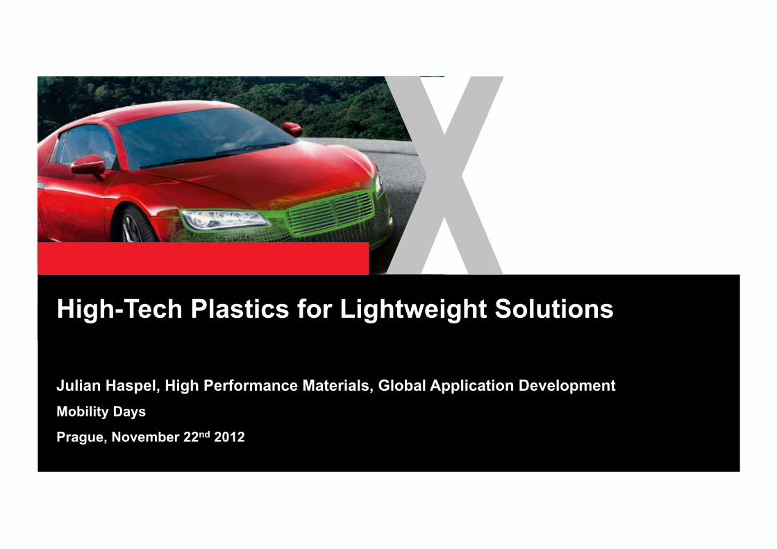
High-Tech Plastics for Lightweight Solutions
Julian Haspel, High Performance Materials, Global Application Development Mobility Days
Prague, November 22nd 2012

Plastic / metal hybrid technology Composite technology CAE – integrative simulation for thermoplastic composites Application fields
2
Agenda
3
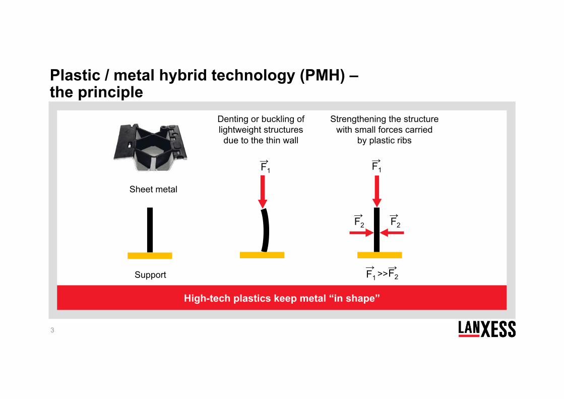
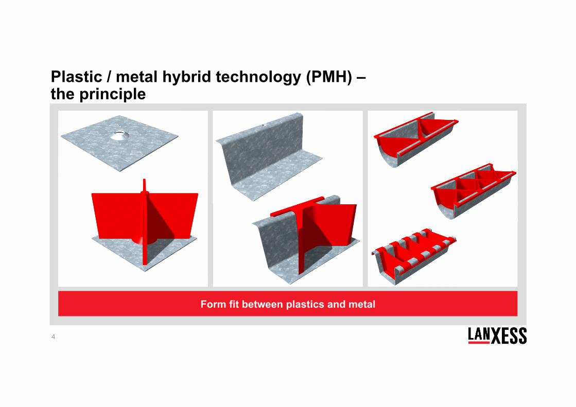
Plastic / metal hybrid technology (PMH) – the principle
High-tech plastics keep metal “in shape”
Sheet metal
Support
F1 →
Denting or buckling of lightweight structures due to the thin wall
F2 F1 → → >>
F1 →
F2 → F2
→
Strengthening the structure with small forces carried
by plastic ribs
4
Form fit between plastics and metal
Plastic / metal hybrid technology (PMH) – the principle
5
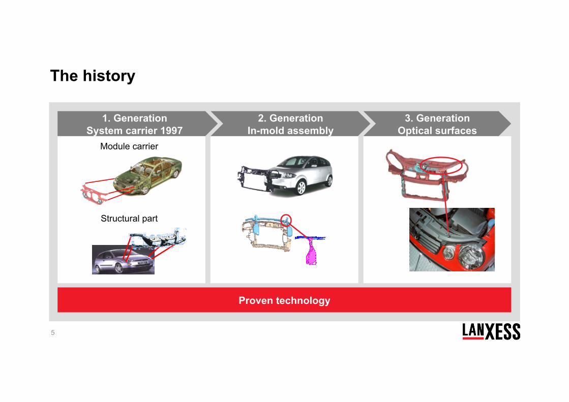
Proven technology
Module carrier
Structural part
1. Generation System carrier 1997
2. Generation In-mold assembly
3. Generation Optical surfaces
The history
6
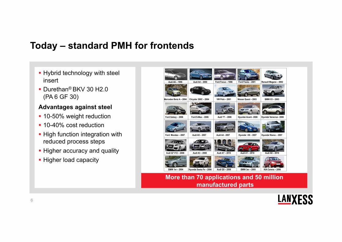
Hybrid technology with steel insert
Durethan® BKV 30 H2.0 (PA 6 GF 30)
Advantages against steel 10-50% weight reduction 10-40% cost reduction High function integration with
reduced process steps Higher accuracy and quality Higher load capacity
More than 70 applications and 50 million manufactured parts
Today – standard PMH for frontends
Ford Mondeo – 2007 Audi A5 – 2007 Audi A4 - 2007 Hyundai i30 – 2007 Hyundai Starex – 2007
Audi Q7 V12 – 2008 Audi A3 – 2008 Audi A7 – 2010 Audi A1 – 2010 Audi A8 – 2010
Mercedes Benz A – 2004 Chrysler 300C – 2004 VW Polo – 2001 Nissan Quest – 2003 BMW X3 – 2003
Audi A6 – 1998 Audi A4 – 2000 Ford Focus – 1998 Ford Fiesta – 2001 Renault Megane – 2002
Ford Galaxy – 2006 Ford S-Max – 2006 Audi TT – 2006 Hyundai Avant– 2006 Hyundai Veracruz– 2006
BMW 1er – 2004 Hyundai Santa Fe – 2006 Audi Q5 – 2008 BMW 3er – 2005 KIA Carens – 2006
7
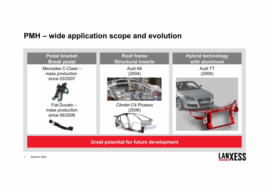
Great potential for future development
Pedal bracket Break pedal
Roof frame Structural inserts
Hybrid technology with aluminum
xxFiat Ducato – mass production since 06/2006
x
Mercedes C-Class – mass production
since 03/2007
Audi TT (2006)
Audi A6 (2004)
Citroën C4 Picasso (2006)
PMH – wide application scope and evolution
Source: Audi
8
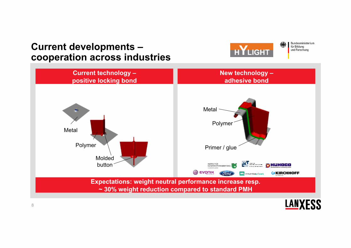
Expectations: weight neutral performance increase resp. ~ 30% weight reduction compared to standard PMH
Current technology – positive locking bond
New technology – adhesive bond
Polymer
Metal
Molded button
Polymer
Metal
Primer / glue
Current developments – cooperation across industries
9
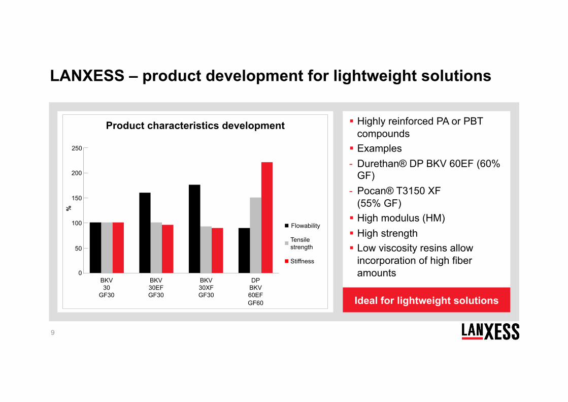
Highly reinforced PA or PBT compounds
Examples - Durethan® DP BKV 60EF (60%
GF) - Pocan® T3150 XF
(55% GF) High modulus (HM) High strength Low viscosity resins allow
incorporation of high fiber amounts
Ideal for lightweight solutions
Product characteristics development
Flowability
Stiffness
Tensile strength
LANXESS – product development for lightweight solutions
0
150
%
200
100
50
250
BKV30
GF30
BKV30EF GF30
BKV30XF GF30
DP BKV60EF GF60
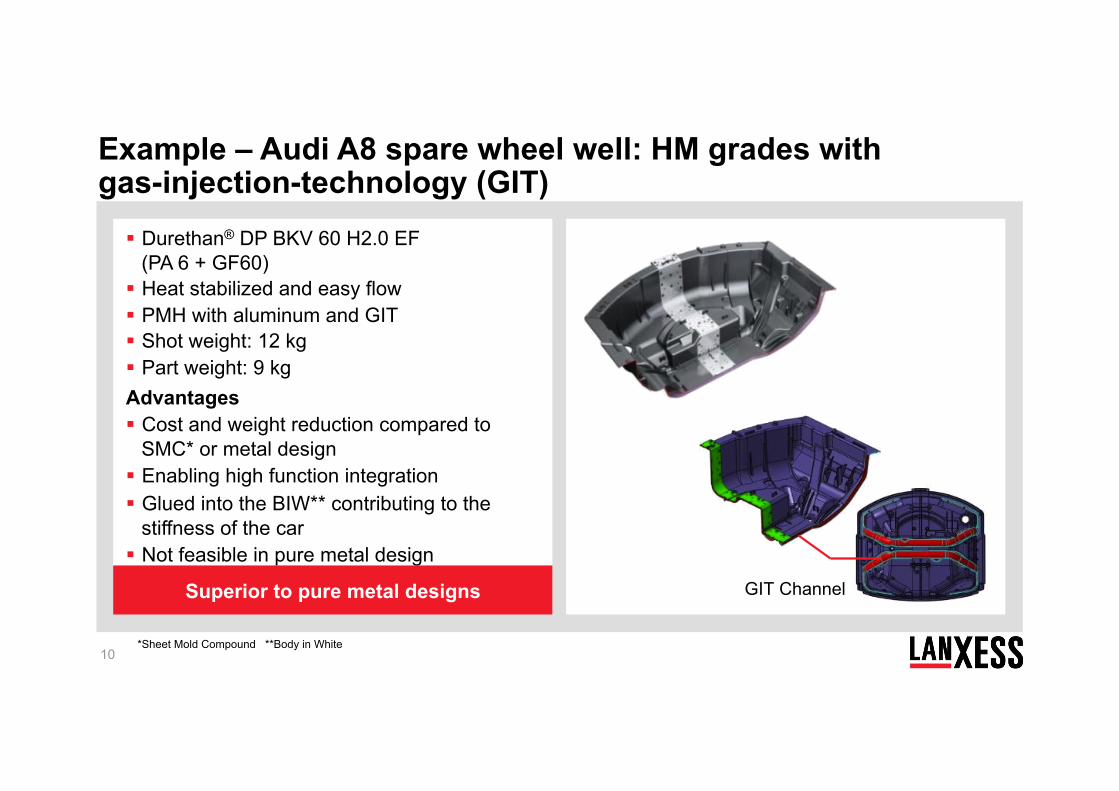
Durethan® DP BKV 60 H2.0 EF (PA 6 + GF60)
Heat stabilized and easy flow PMH with aluminum and GIT Shot weight: 12 kg Part weight: 9 kg
Advantages Cost and weight reduction compared to
SMC* or metal design Enabling high function integration Glued into the BIW** contributing to the
stiffness of the car Not feasible in pure metal design
10
Superior to pure metal designs
*Sheet Mold Compound **Body in White
GIT Channel
Example – Audi A8 spare wheel well: HM grades with gas-injection-technology (GIT)

Plastic / metal hybrid technology Composite technology CAE – integrative simulation for thermoplastic composites Application fields
11
Agenda
12
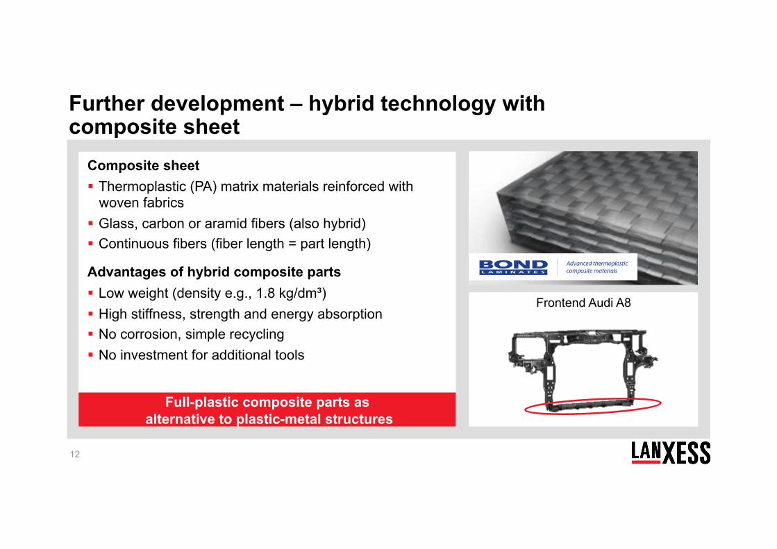
Frontend Audi A8
Composite sheet Thermoplastic (PA) matrix materials reinforced with
woven fabrics Glass, carbon or aramid fibers (also hybrid) Continuous fibers (fiber length = part length)
Advantages of hybrid composite parts Low weight (density e.g., 1.8 kg/dm³) High stiffness, strength and energy absorption No corrosion, simple recycling No investment for additional tools
Full-plastic composite parts as alternative to plastic-metal structures
Further development – hybrid technology with composite sheet
.
13
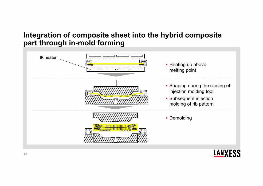
IR heater
Heating up above melting point
Shaping during the closing of injection molding tool
Subsequent injection molding of rib pattern
Demolding
Integration of composite sheet into the hybrid composite part through in-mold forming
14
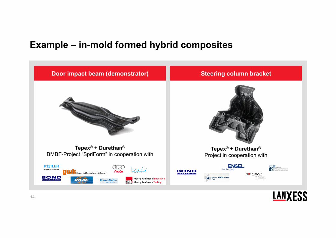
Door impact beam (demonstrator) Steering column bracket
Tepex® + Durethan® BMBF-Project “SpriForm” in cooperation with
Tepex® + Durethan® Project in cooperation with
Example – in-mold formed hybrid composites
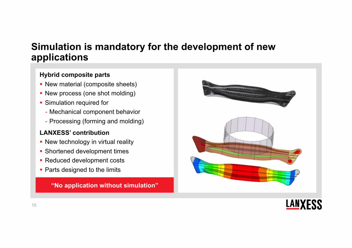
Hybrid composite parts New material (composite sheets) New process (one shot molding) Simulation required for
- Mechanical component behavior - Processing (forming and molding)
LANXESS’ contribution New technology in virtual reality Shortened development times Reduced development costs Parts designed to the limits
15
“No application without simulation”
Simulation is mandatory for the development of new applications
Plastic / metal hybrid technology Composite technology CAE – integrative simulation for thermoplastic composites Application fields
16
Agenda
17
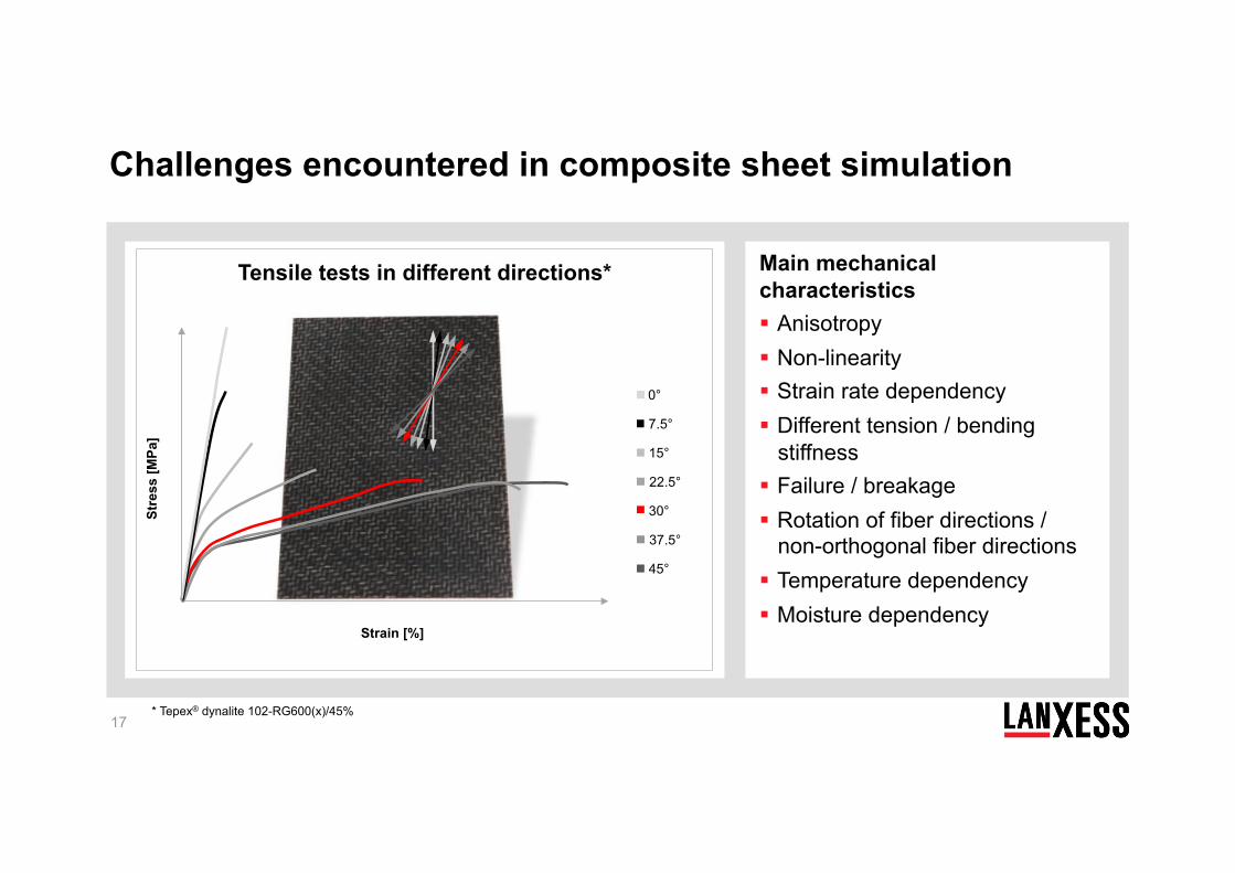
Main mechanical characteristics Anisotropy Non-linearity Strain rate dependency Different tension / bending
stiffness Failure / breakage Rotation of fiber directions /
non-orthogonal fiber directions Temperature dependency Moisture dependency
* Tepex® dynalite 102-RG600(x)/45%
Tensile tests in different directions*
Stre
ss [M
Pa]
Strain [%]
0°
7.5°
15°
22.5°
30°
37.5°
45°
Challenges encountered in composite sheet simulation
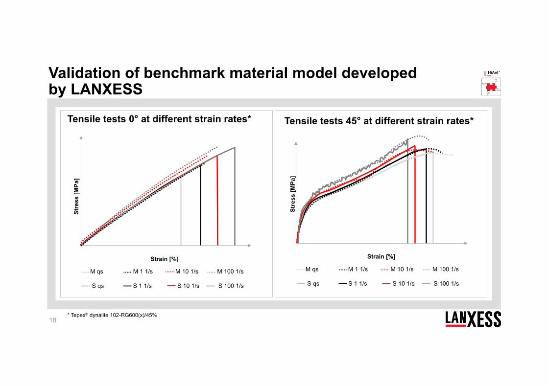
18 * Tepex® dynalite 102-RG600(x)/45%
Tensile tests 45° at different strain rates*
Stre
ss [M
Pa]
Strain [%]
M 1 1/s M 10 1/s M qs M 100 1/s
S 1 1/s S 10 1/s S qs S 100 1/s
Validation of benchmark material model developed by LANXESS
Tensile tests 0° at different strain rates*
Stre
ss [M
Pa]
Strain [%]
M 1 1/s M 10 1/s M qs M 100 1/s
S 1 1/s S 10 1/s S qs S 100 1/s
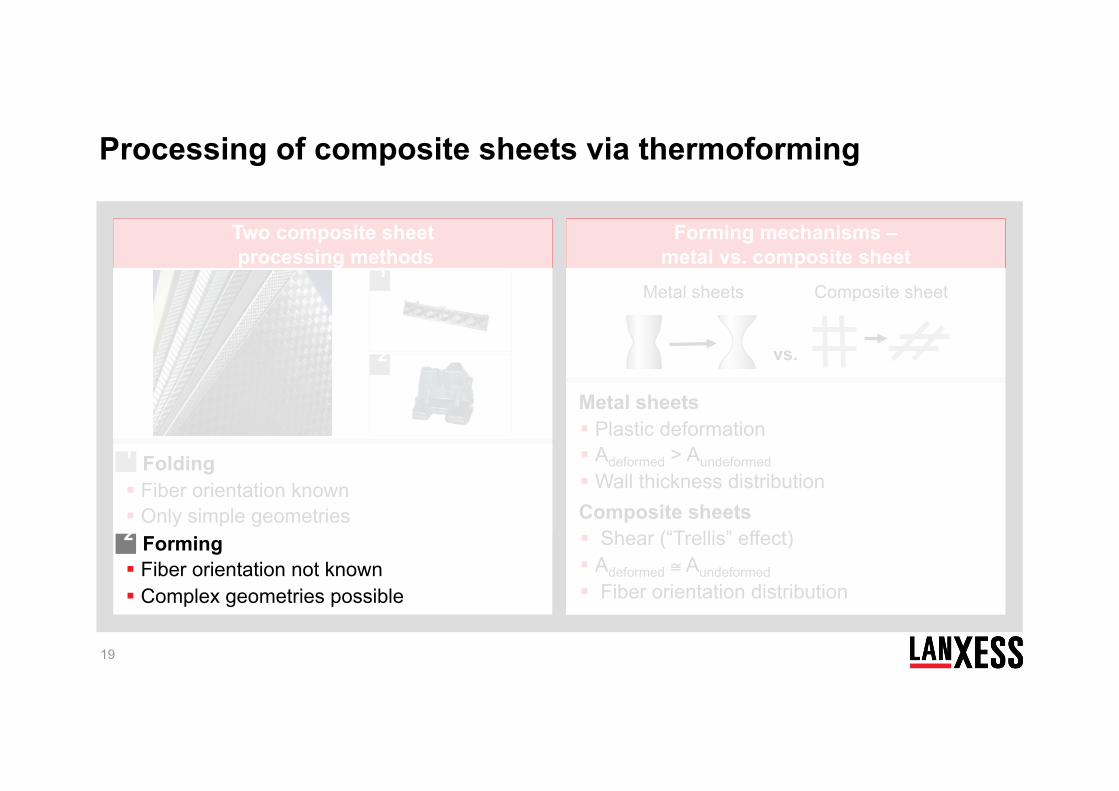
Folding Fiber orientation known Only simple geometries Forming Fiber orientation not known Complex geometries possible
19
Two composite sheet processing methods
Forming mechanisms – metal vs. composite sheet
Metal sheets Plastic deformation Adeformed > Aundeformed Wall thickness distribution Composite sheets Shear (“Trellis” effect) Adeformed ≅ Aundeformed Fiber orientation distribution
1
2
1
2
Metal sheets Composite sheet
vs.
Processing of composite sheets via thermoforming
Two composite sheet processing methods
Forming mechanisms – metal vs. composite sheet
Forming mechanisms – metal vs. composite sheet
20
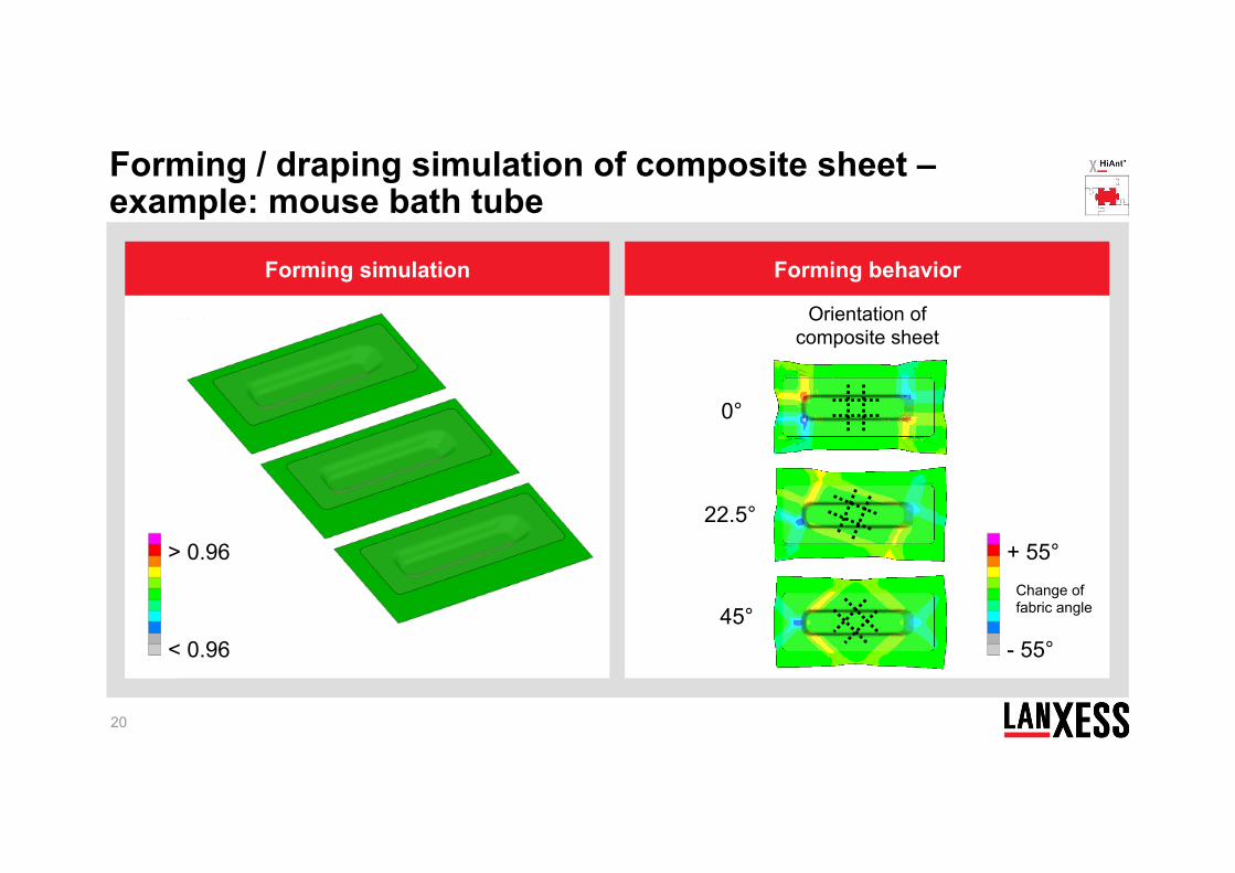
Forming simulation Forming behavior
> 0.96
< 0.96
+ 55°
- 55°
Change of fabric angle
0°
22.5°
45°
Orientation of composite sheet
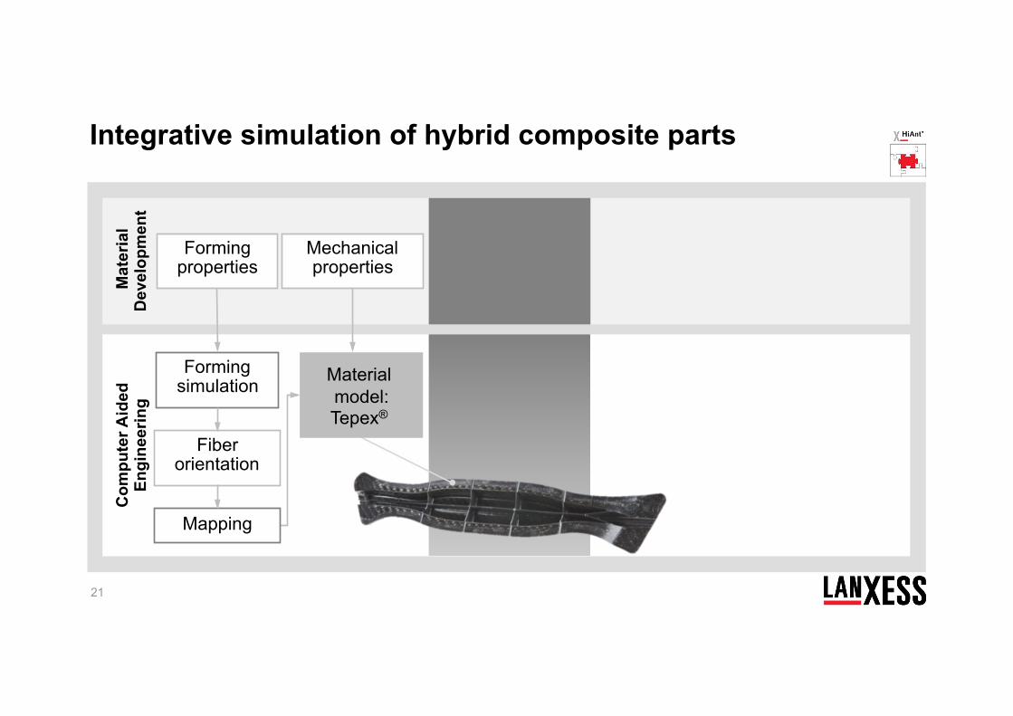
Forming / draping simulation of composite sheet – example: mouse bath tube
21
Forming simulation
Fiber orientation
Forming properties
Mapping
Mat
eria
l D
evel
opm
ent
Com
pute
r Aid
ed
Engi
neer
ing
Mechanical properties
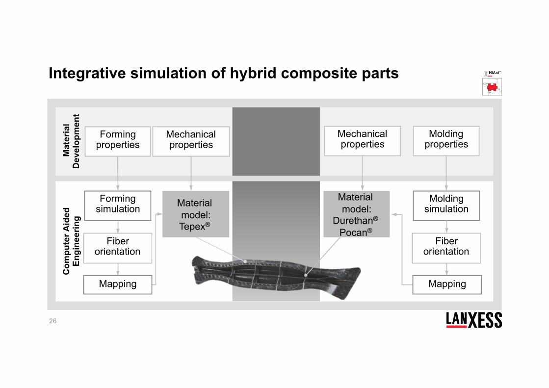
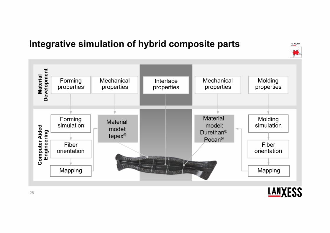
Integrative simulation of hybrid composite parts
Material model: Tepex®
22
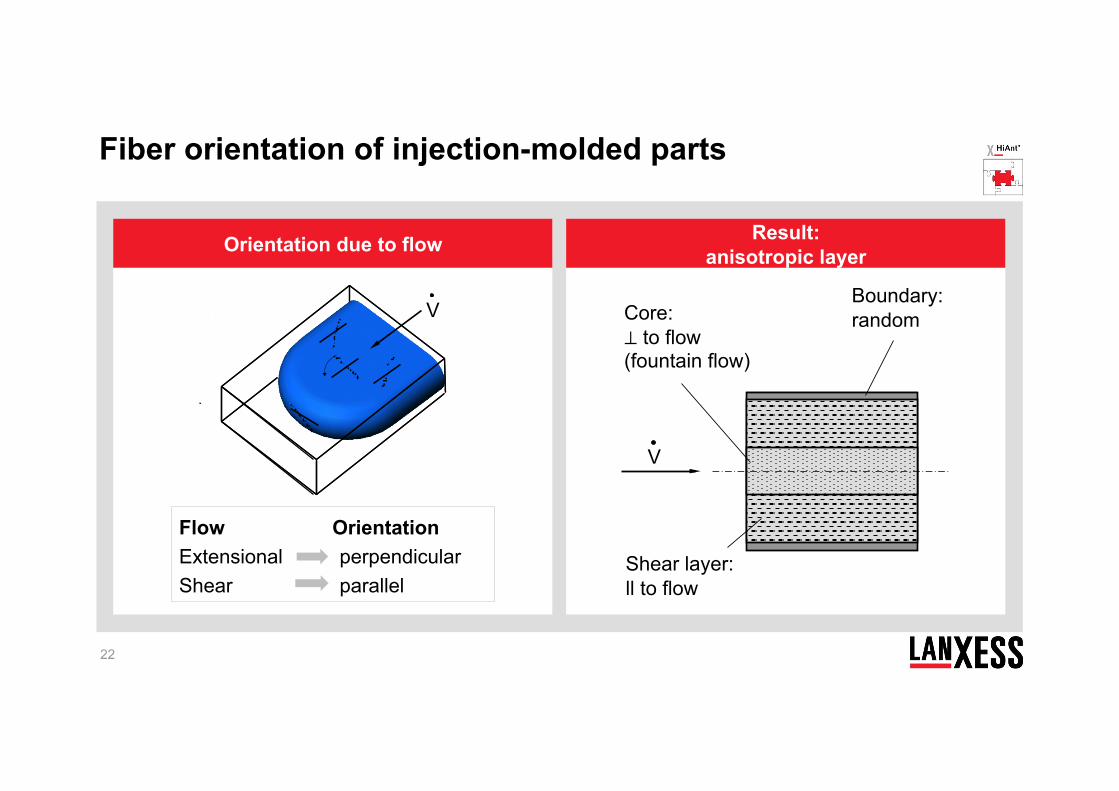
Orientation due to flow Result: anisotropic layer
V
Flow Orientation Extensional perpendicular Shear parallel
Shear layer: ll to flow
Core: ⊥ to flow (fountain flow)
V
Boundary: random
Fiber orientation of injection-molded parts
23
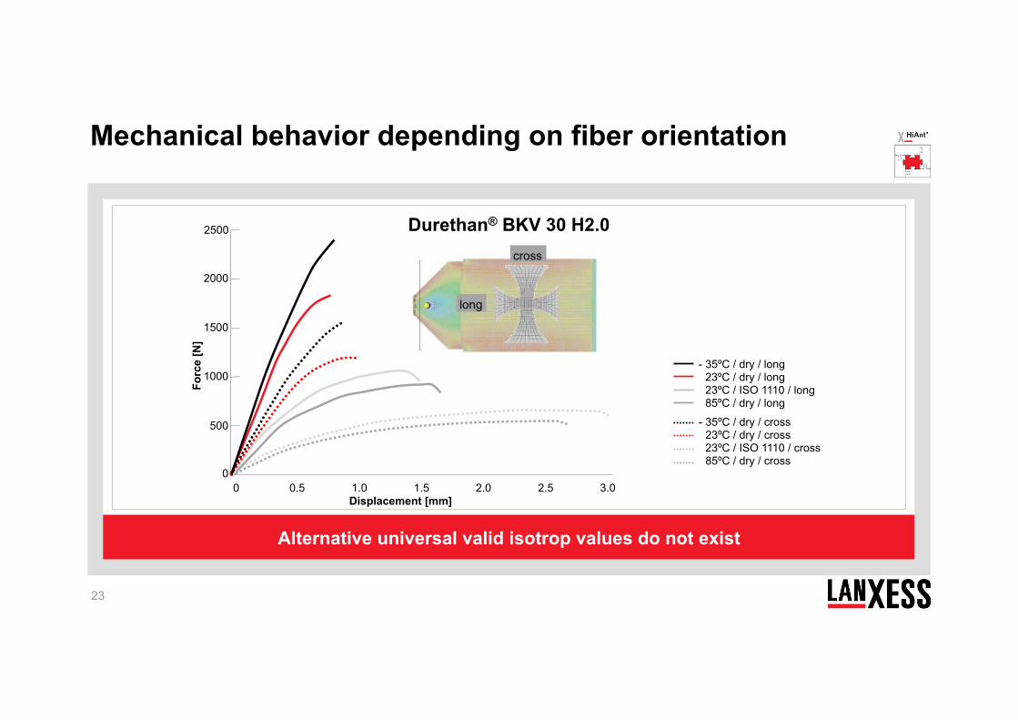
Alternative universal valid isotrop values do not exist
Durethan® BKV 30 H2.0
0
1500
Forc
e [N
]
2000
1000
500
2500
0.5 1.0 1.5 2.0 Displacement [mm]
0 3.0 2.5
long
cross
- 35ºC / dry / long 23ºC / dry / long 23ºC / ISO 1110 / long 85ºC / dry / long
- 35ºC / dry / cross 23ºC / dry / cross 23ºC / ISO 1110 / cross 85ºC / dry / cross
Mechanical behavior depending on fiber orientation
24
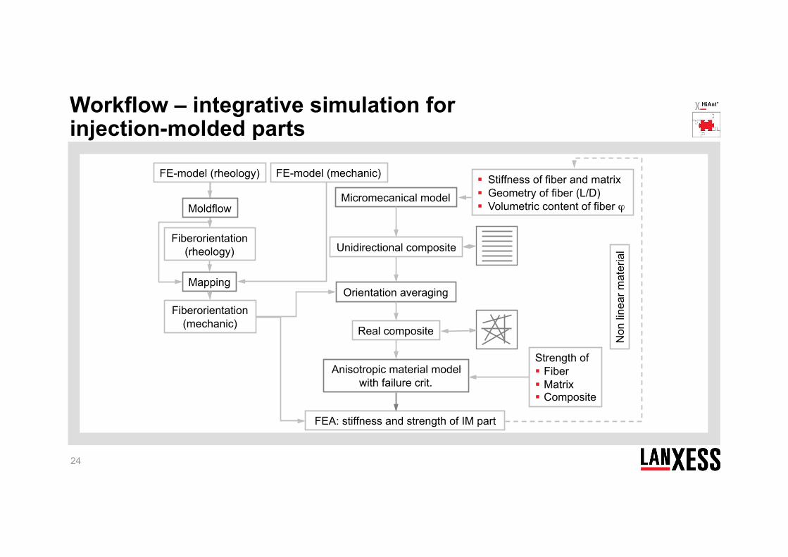
FE-model (rheology) FE-model (mechanic)
Fiberorientation (rheology)
Mapping
FEA: stiffness and strength of IM part
Stiffness of fiber and matrix Geometry of fiber (L/D) Volumetric content of fiber ϕ
Anisotropic material model with failure crit.
Orientation averaging
Strength of Fiber Matrix Composite
Micromecanical model
Unidirectional composite
Real composite
Fiberorientation (mechanic)
Non
line
ar m
ater
ial
Moldflow
Workflow – integrative simulation for injection-molded parts
25
Displacement [mm]
Forc
e [N
]
600
900
100
200
0.4 0.6 0.2 1.4 2.4 1.8
1000
700
1100
500
800
400
300
1.2 2.0 1.0 2.2 0.8 1.6 0
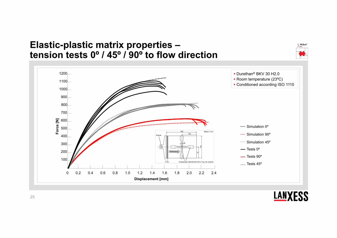
1200 Durethan® BKV 30 H2.0 Room temperature (23ºC) Conditioned according ISO 1110
Simulation 0º
Simulation 90º
Simulation 45º
Tests 0º
Tests 90º
Tests 45º
Elastic-plastic matrix properties – tension tests 0º / 45º / 90º to flow direction
26
Forming simulation
Fiber orientation
Forming properties
Material model: Tepex®
Mapping
Mechanical properties
Molding properties
Molding simulation
Fiber orientation
Mechanical properties
Material model:
Durethan® Pocan®
Mapping
Integrative simulation of hybrid composite parts M
ater
ial
Dev
elop
men
t C
ompu
ter A
ided
En
gine
erin
g
27
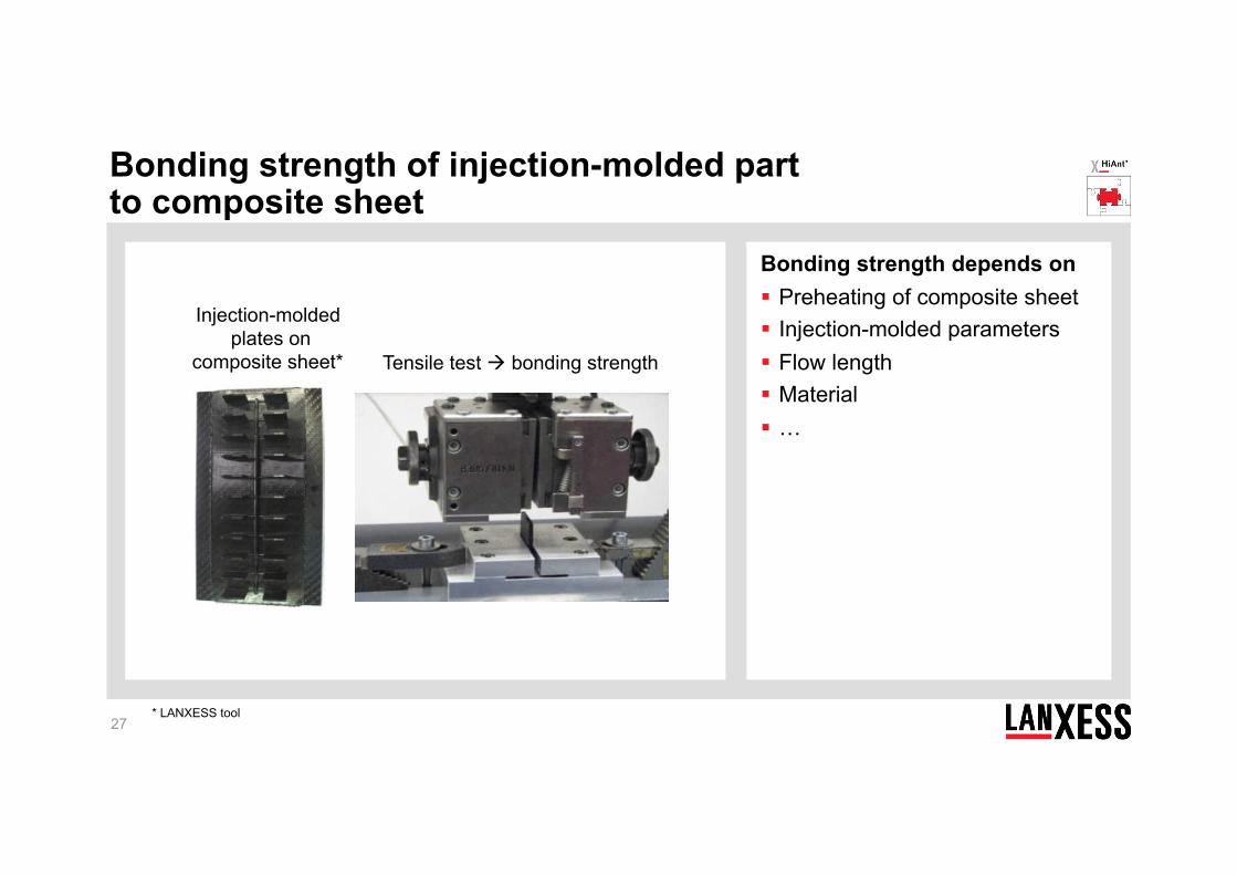
Bonding strength depends on Preheating of composite sheet Injection-molded parameters Flow length Material …
* LANXESS tool
Injection-molded plates on
composite sheet* Tensile test bonding strength
Bonding strength of injection-molded part to composite sheet
28
Forming simulation
Fiber orientation
Forming properties
Mapping
Mechanical properties
Molding properties
Molding simulation
Fiber orientation
Mechanical properties
Material model:
Durethan® Pocan®
Mapping
Interface properties
Integrative simulation of hybrid composite parts M
ater
ial
Dev
elop
men
t C
ompu
ter A
ided
En
gine
erin
g
Material model: Tepex®
29
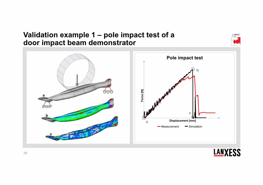
a
b
c
Pole impact test
Forc
e [N
]
Displacement [mm] a
b
c
Measurement Simulation
Validation example 1 – pole impact test of a door impact beam demonstrator
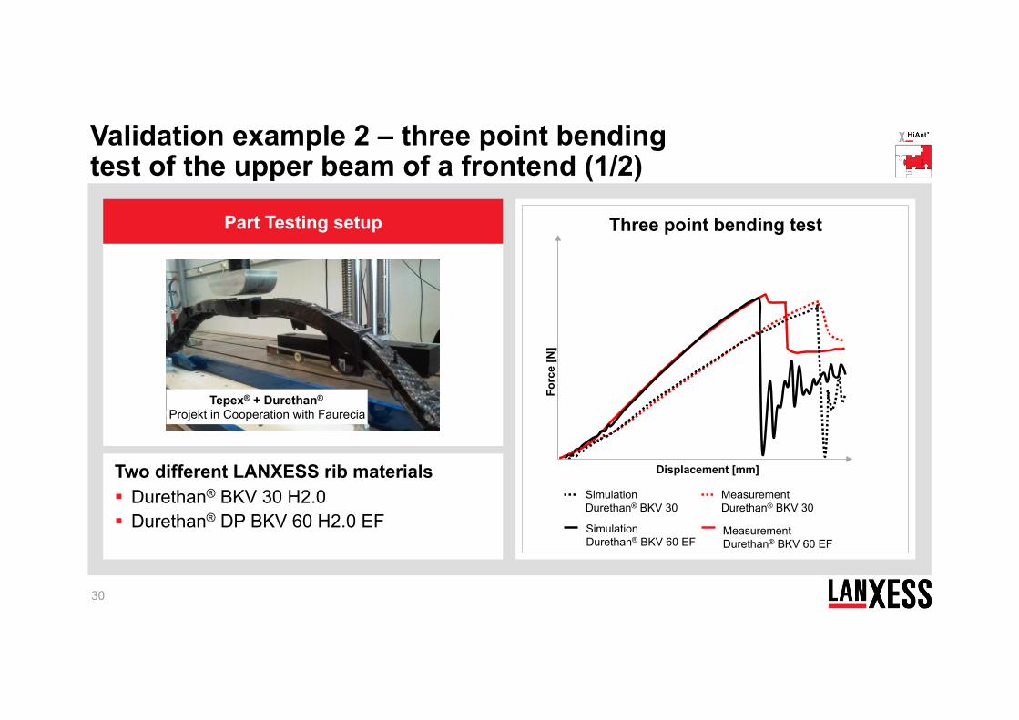
Two different LANXESS rib materials Durethan® BKV 30 H2.0 Durethan® DP BKV 60 H2.0 EF
30
Part Testing setup
Tepex® + Durethan® Projekt in Cooperation with Faurecia
Three point bending test
Forc
e [N
]
Displacement [mm]
Simulation Durethan® BKV 60 EF
Measurement Durethan® BKV 60 EF
Simulation Durethan® BKV 30
Measurement Durethan® BKV 30
Validation example 2 – three point bending test of the upper beam of a frontend (1/2)
31
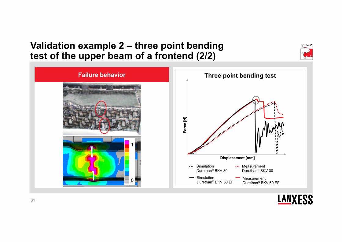
Three point bending test
Forc
e [N
]
Displacement [mm]
1
0
Failure behavior
Validation example 2 – three point bending test of the upper beam of a frontend (2/2)
Simulation Durethan® BKV 60 EF
Measurement Durethan® BKV 60 EF
Simulation Durethan® BKV 30
Measurement Durethan® BKV 30
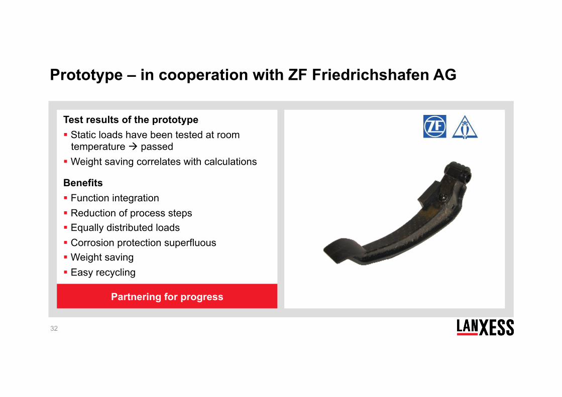
Test results of the prototype Static loads have been tested at room
temperature passed Weight saving correlates with calculations
Benefits Function integration Reduction of process steps Equally distributed loads Corrosion protection superfluous Weight saving Easy recycling
32
Partnering for progress
Prototype – in cooperation with ZF Friedrichshafen AG
33
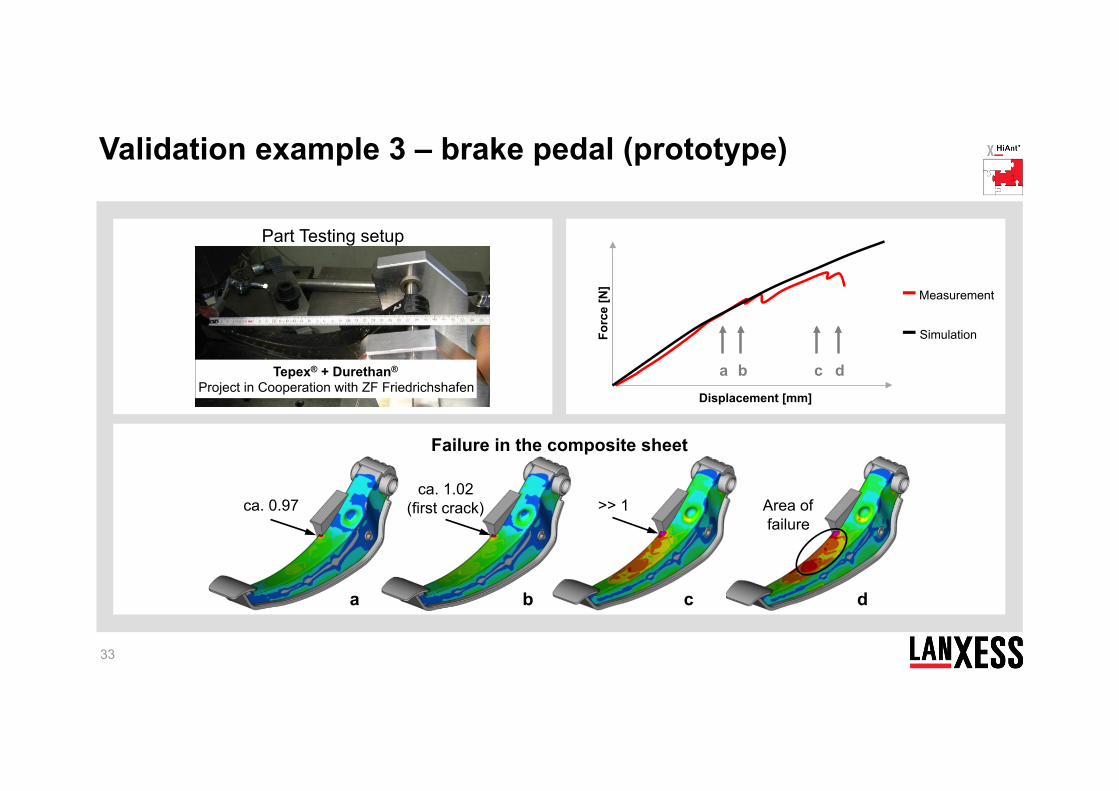
Failure in the composite sheet
Part Testing setup
Tepex® + Durethan® Project in Cooperation with ZF Friedrichshafen
a b c d
Forc
e [N
]
Displacement [mm]
Measurement
Simulation
ca. 0.97 ca. 1.02
(first crack) Area of failure
>> 1
a b c d
Validation example 3 – brake pedal (prototype)
Plastic / metal hybrid technology Composite technology CAE – integrative simulation for thermoplastic composites Application fields
34
Agenda
35
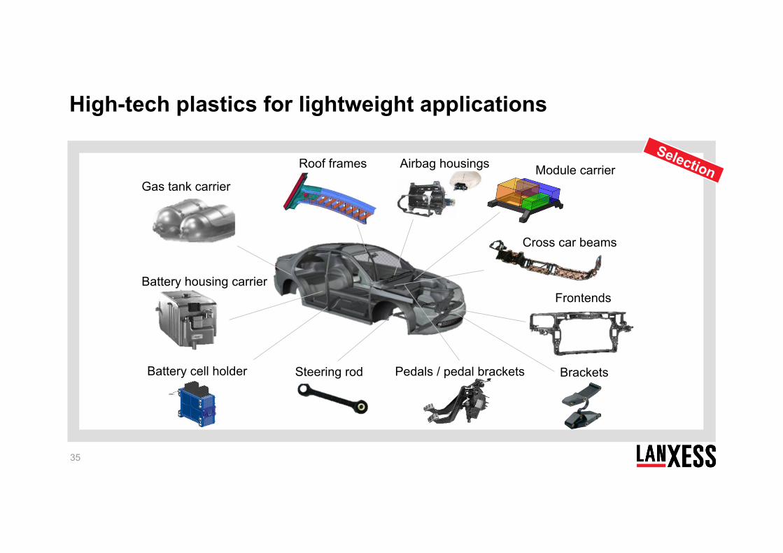
Selection
Steering rod
Airbag housings
Cross car beams
Frontends
Battery cell holder
Battery housing carrier
Pedals / pedal brackets Brackets
Gas tank carrier Module carrier Roof frames
High-tech plastics for lightweight applications
36
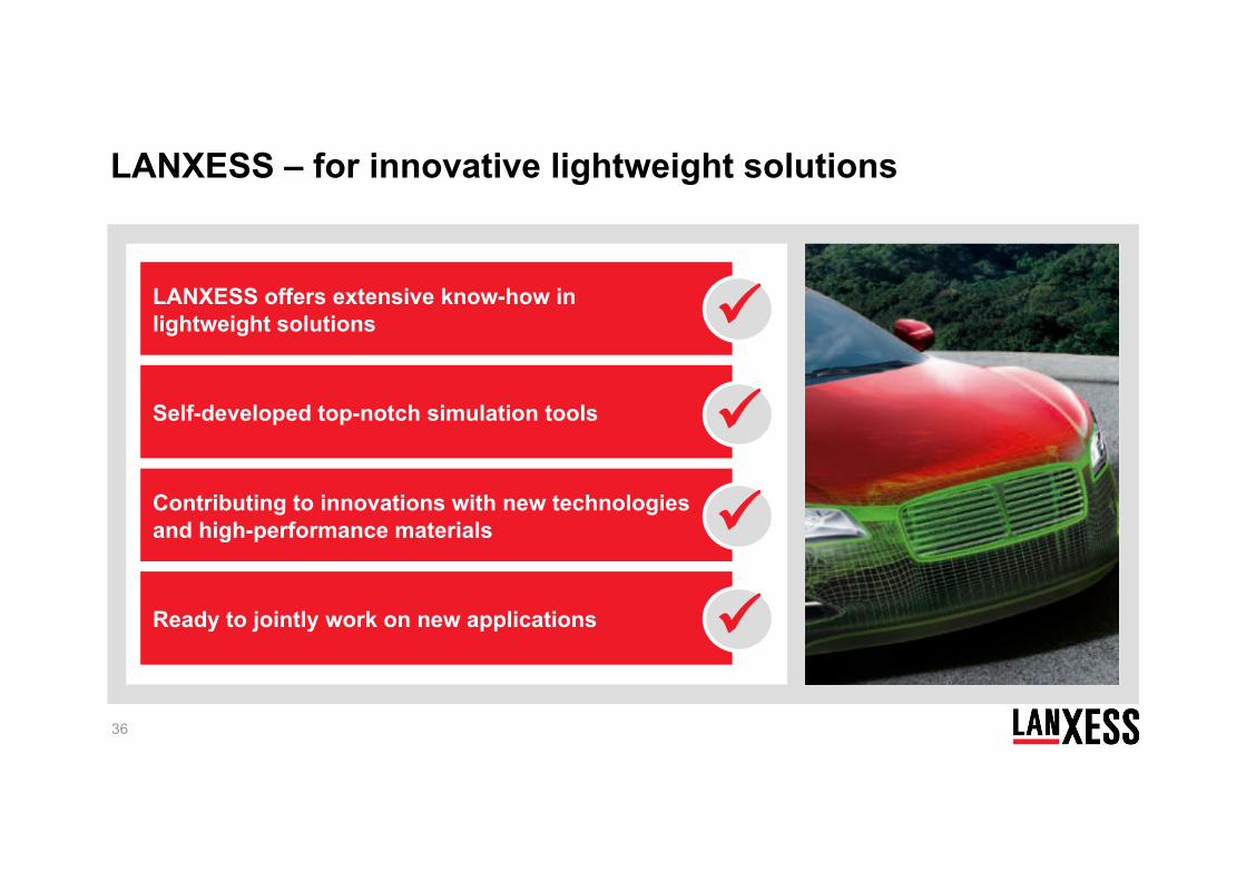
LANXESS – for innovative lightweight solutions
LANXESS offers extensive know-how in lightweight solutions Self-developed top-notch simulation tools Contributing to innovations with new technologies and high-performance materials Ready to jointly work on new applications