Embed Size (px)
Citation preview
Supplementary Material (ESI) for CrystEngComm This journal is (c) The Royal Society of Chemistry 2011
Electronic Supplementary Information
High Symmetric Polyhedral Cu2O Crystals with Controllable-Index Planes
Shaodong Sun, Chuncai Kong, Shengchun Yang, Liqun Wang, Xiaoping Song, Bingjun Ding, and
Zhimao Yang*
*E-mail: [email protected]
20 30 40 50 60 70 80
Inte
nsity
(a. u
.)
2Theta(degree)
(110
)
(111
)
(200
)
(211
)
(220
)
(311
)(2
22)
Fig. S1 XRD pattern of the typical as-prepared 50-facet polyhedral Cu2O crystals.
Fig. S2 The size-distribution diagram of as-prepared 50-facet polyhedral Cu2O crystals.
Supplementary Material (ESI) for CrystEngComm This journal is (c) The Royal Society of Chemistry 2011
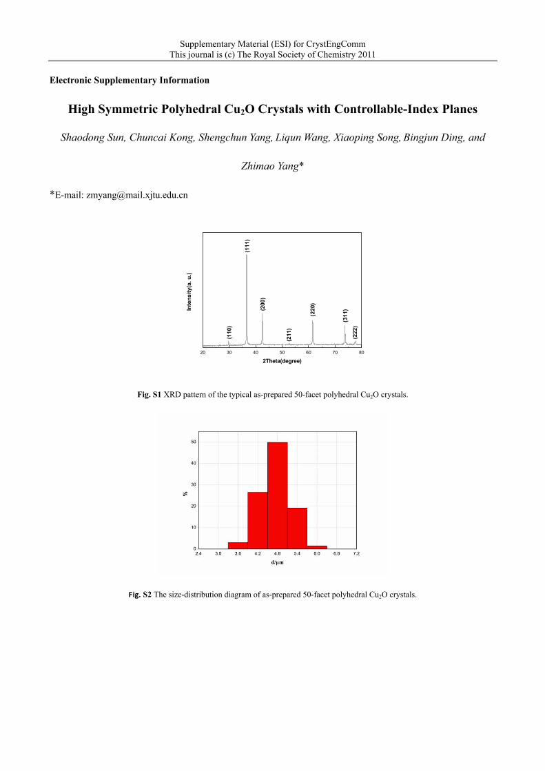
Fig. S3 Determining the facets of 50-facet polyhedral Cu2O crystals as shown in Fig. 1. (a) SEM image of a 50-facet polyhedral Cu2O
architecture; (b) and (c) interfacial angles of the 50-facet polyhedral Cu2O crystal; (d) interfacial angles of a 50-facet polyhedral Cu2O
bounded by different facets; (e) calculated and theoretical values of interfacial angles of the 50-facet polyhedral Cu2O bounded by
different facets; (f) corresponding planes of the 50-facet polyhedral Cu2O bounded by different facets.
Supplementary Material (ESI) for CrystEngComm This journal is (c) The Royal Society of Chemistry 2011
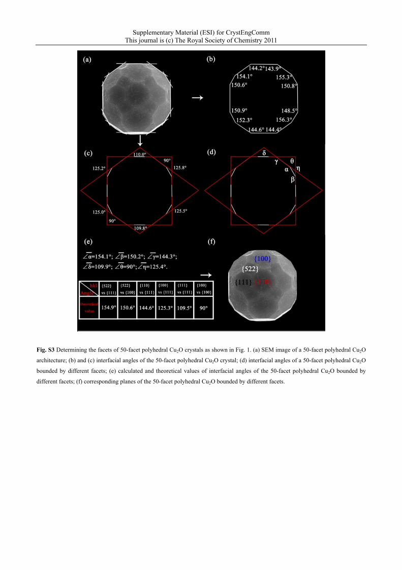
Fig. S4 The enlarged FE-SEM images of the shapes obtained at different reaction time, which can illuminate the shape evolution
process from 50-facets to 26-facets polyhedral architectures. (a) 5.5 min; (b) 6.0 min; (c) 7.0 min; (d) 8.0 min; (e) Scheme showing the
disappearance process of {522} facets.
Supplementary Material (ESI) for CrystEngComm This journal is (c) The Royal Society of Chemistry 2011
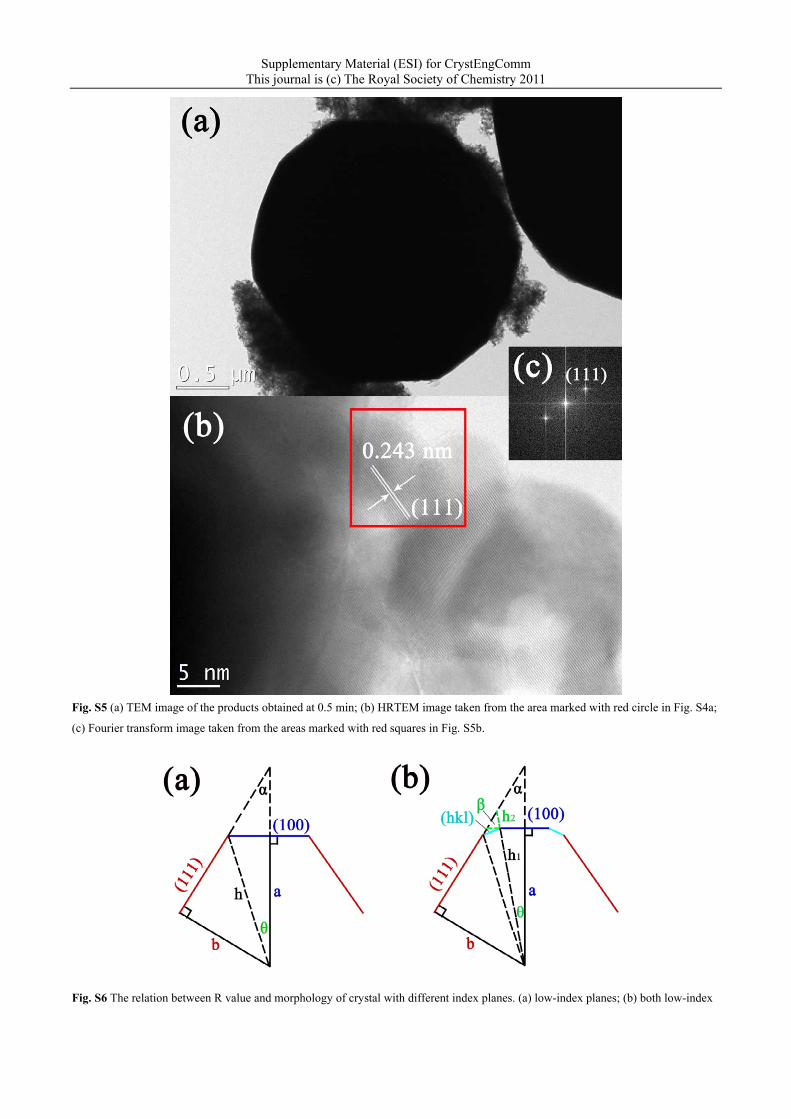
Fig. S5 (a) TEM image of the products obtained at 0.5 min; (b) HRTEM image taken from the area marked with red circle in Fig. S4a;
(c) Fourier transform image taken from the areas marked with red squares in Fig. S5b.
Fig. S6 The relation between R value and morphology of crystal with different index planes. (a) low-index planes; (b) both low-index
Supplementary Material (ESI) for CrystEngComm This journal is (c) The Royal Society of Chemistry 2011
planes and high-index {hkl} planes.
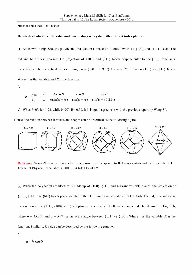
Detailed calculations of R value and morphology of crystal with different index planes:
(1) As shown in Fig. S6a, the polyhedral architecture is made up of only low-index {100} and {111} facets. The
red and blue lines represent the projection of {100} and {111} facets perpendicular to the [110] zone axis,
respectively. The theoretical values of angle α = (180°-109.5°) ÷ 2 = 35.25° between {111} vs {111} facets.
Where θ is the variable, and R is the function.
∵
{100}
{111}
cos cos cossin( ) sin( ) sin( 35.25 )
v a hRv b h
θ θ θθ α θ α θ
= = = = =+ + + °
∴ When θ=0°, R= 1.73, while θ=90°, R= 0.58. It is in good agreement with the previous report by Wang ZL.
Hence, the relation between R values and shapes can be described as the following figure.
Reference: Wang ZL. Transmission electron microscopy of shape-controlled nanocrystals and their assemblies[J]. Journal of Physical Chemistry B, 2000, 104 (6): 1153-1175.
(2) When the polyhedral architecture is made up of {100}, {111} and high-index {hkl} planes, the projection of
{100}, {111} and {hkl} facets perpendicular to the [110] zone axis was shown in Fig. S6b. The red, blue and cyan,
lines represent the {111}, {100} and {hkl} planes, respectively. The R value can be calculated based on Fig. S6b,
where α = 35.25°, and β = 54.7° is the acute angle between {111} vs {100}. Where θ is the variable, R is the
function. Similarly, R value can be described by the following equation.
∵
1 cosa h θ=
Supplementary Material (ESI) for CrystEngComm This journal is (c) The Royal Society of Chemistry 2011
1sin( ) cos tan sin sin sin[ ]
1 cos sinb h θ α θ α β θ β
α β+ − ⋅ ⋅ − ⋅=
− ⋅
{100}
{111}
(1 cos sin ) cossin( ) cos tan sin sin sin
v aRv b
α β θθ α θ α β θ β
− ⋅= = =+ − ⋅ ⋅ − ⋅
∴ (1 cos35.25 sin 54.7 )cos
sin( 35.25 ) cos tan 35.25 sin 54.7 sin sin 54.7R θ
θ θ θ− °⋅ °=
+ ° − ⋅ ° ⋅ ° − ⋅ °
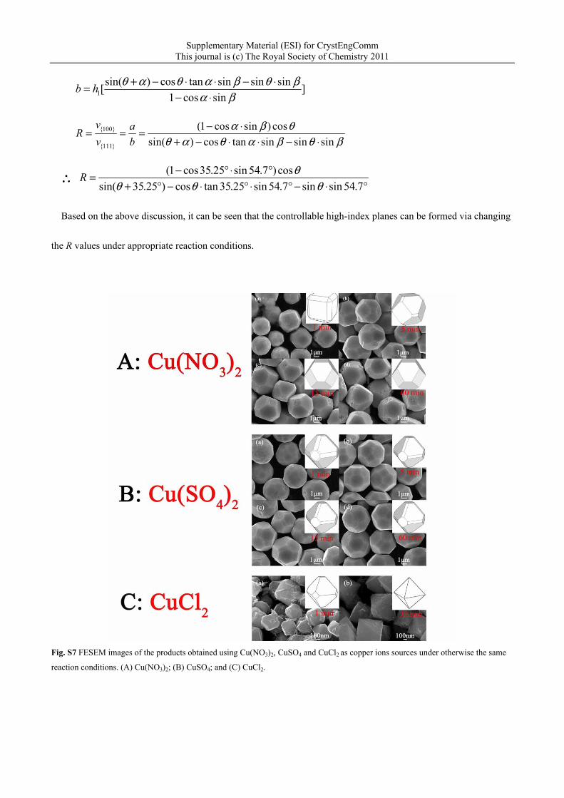
Based on the above discussion, it can be seen that the controllable high-index planes can be formed via changing
the R values under appropriate reaction conditions.
Fig. S7 FESEM images of the products obtained using Cu(NO3)2, CuSO4 and CuCl2 as copper ions sources under otherwise the same
reaction conditions. (A) Cu(NO3)2; (B) CuSO4; and (C) CuCl2.
Supplementary Material (ESI) for CrystEngComm This journal is (c) The Royal Society of Chemistry 2011
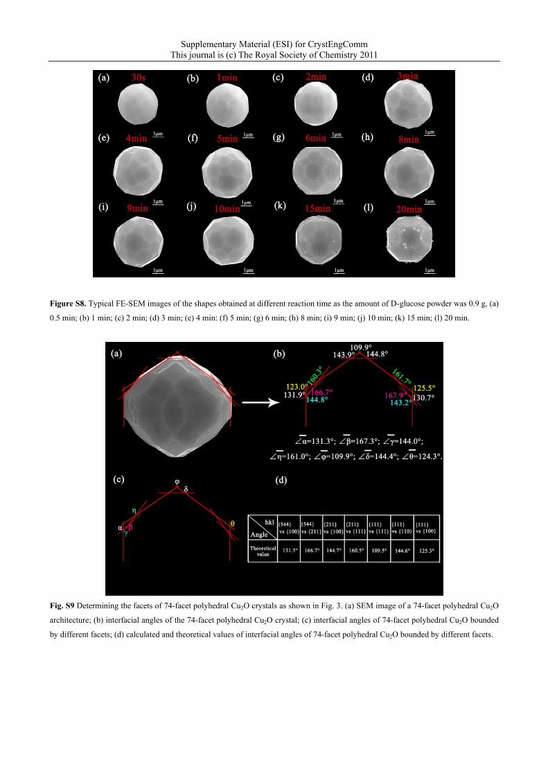
Figure S8. Typical FE-SEM images of the shapes obtained at different reaction time as the amount of D-glucose powder was 0.9 g, (a)
0.5 min; (b) 1 min; (c) 2 min; (d) 3 min; (e) 4 min: (f) 5 min; (g) 6 min; (h) 8 min; (i) 9 min; (j) 10 min; (k) 15 min; (l) 20 min.
Fig. S9 Determining the facets of 74-facet polyhedral Cu2O crystals as shown in Fig. 3. (a) SEM image of a 74-facet polyhedral Cu2O
architecture; (b) interfacial angles of the 74-facet polyhedral Cu2O crystal; (c) interfacial angles of 74-facet polyhedral Cu2O bounded
by different facets; (d) calculated and theoretical values of interfacial angles of 74-facet polyhedral Cu2O bounded by different facets.
Supplementary Material (ESI) for CrystEngComm This journal is (c) The Royal Society of Chemistry 2011
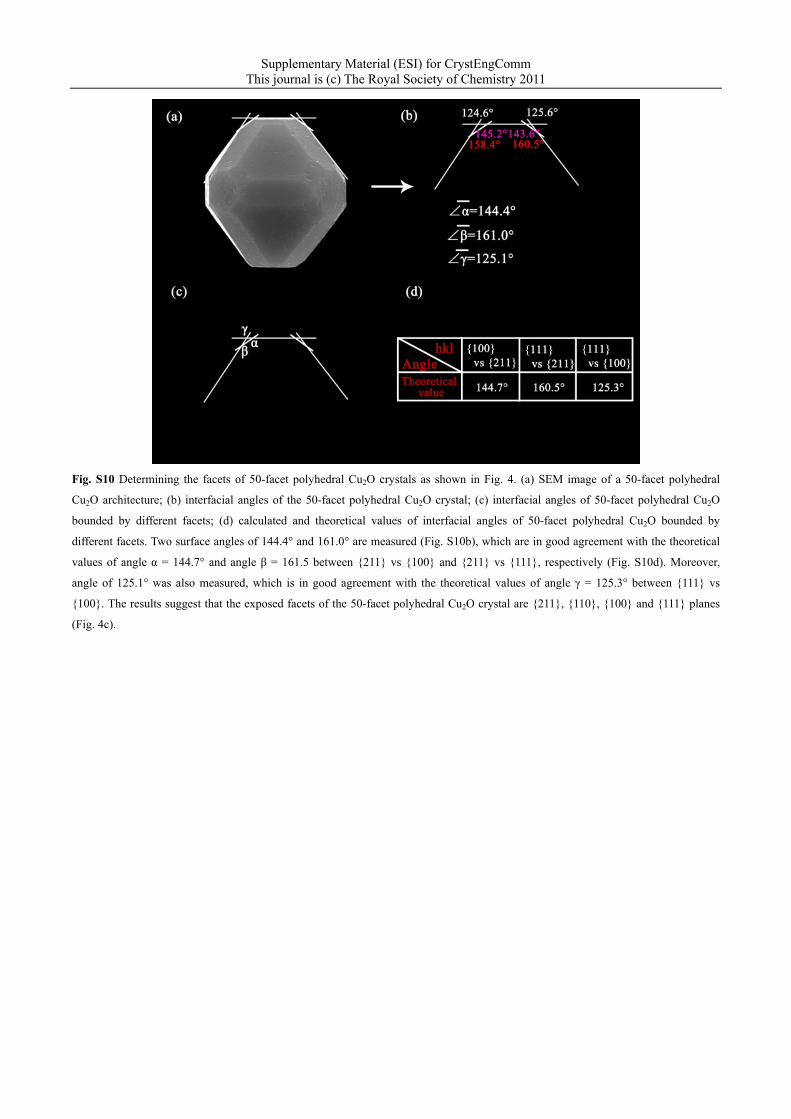
Fig. S10 Determining the facets of 50-facet polyhedral Cu2O crystals as shown in Fig. 4. (a) SEM image of a 50-facet polyhedral
Cu2O architecture; (b) interfacial angles of the 50-facet polyhedral Cu2O crystal; (c) interfacial angles of 50-facet polyhedral Cu2O
bounded by different facets; (d) calculated and theoretical values of interfacial angles of 50-facet polyhedral Cu2O bounded by
different facets. Two surface angles of 144.4° and 161.0° are measured (Fig. S10b), which are in good agreement with the theoretical
values of angle α = 144.7° and angle β = 161.5 between {211} vs {100} and {211} vs {111}, respectively (Fig. S10d). Moreover,
angle of 125.1° was also measured, which is in good agreement with the theoretical values of angle γ = 125.3° between {111} vs
{100}. The results suggest that the exposed facets of the 50-facet polyhedral Cu2O crystal are {211}, {110}, {100} and {111} planes
(Fig. 4c).
Supplementary Material (ESI) for CrystEngComm This journal is (c) The Royal Society of Chemistry 2011
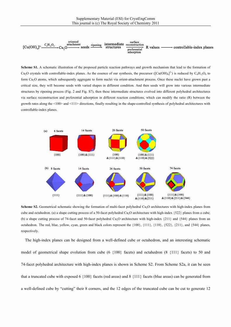
Scheme S1. A schematic illustration of the proposed particle reaction pathways and growth mechanism that lead to the formation of
Cu2O crystals with controllable-index planes. As the essence of our synthesis, the precursor ([Cu(OH)4]2-) is reduced by C6H12O6 to
form Cu2O atoms, which subsequently aggregate to form nuclei via orient-attachment process. Once these nuclei have grown past a
critical size, they will become seeds with varied shapes in different condition. And then seeds will grow into various intermediate
structures by ripening process (Fig. 2 and Fig. S7), then these intermediate structures evolved into different polyhedral architectures
via surface reconstruction and preferential adsorption in different reaction conditions, which can modify the ratio (R) between the
growth rates along the <100> and <111> directions, finally resulting in the shape-controlled synthesis of polyhedral architectures with
controllable-index planes.
Scheme S2. Geometrical schematic showing the formation of multi-facet polyhedral Cu2O architectures with high-index planes from
cube and octahedron. (a) a shape cutting process of a 50-facet polyhedral Cu2O architecture with high-index {522} planes from a cube;
(b) a shape cutting process of 74-facet and 50-facet polyhedral Cu2O architecture with high-index {211} and {544} planes from an
octahedron. The red, blue, yellow, cyan, green and black colors represent the {100}, {111}, {110}, {522}, {211}, and {544} planes,
respectively.
The high-index planes can be designed from a well-defined cube or octahedron, and an interesting schematic
model of geometrical shape evolution from cube (6 {100} facets) and octahedron (8 {111} facets) to 50 and
74-facet polyhedral architecture with high-index planes is shown in Scheme S2. From Scheme S2a, it can be seen
that a truncated cube with exposed 6 {100} facets (red areas) and 8 {111} facets (blue areas) can be generated from
a well-defined cube by “cutting” their 8 corners, and the 12 edges of the truncated cube can be cut to generate 12
Supplementary Material (ESI) for CrystEngComm This journal is (c) The Royal Society of Chemistry 2011
rectangular {110} facets (yellow areas), finally a high symmetric 50-facet polyhedron with high-index {522} facets
(cyan areas) is formed by further cutting the joints of square, triangular and rectangular facets of a truncated edges
cube. This 50-facet polyhedral structure with high-index {522} facets (Fig. 1) can be viewed as a result of cutting a
cube. Similarly, another 50-facets polyhedral architecture (Fig. 4) with high-index {211} facets (green areas) can be
fabricated via cutting an octahedron (Scheme S2b), and 74-facets polyhedral architecture (Fig. 3) with high-index
{544} facets (black areas) is also formed by further cutting the edges between {100} (red areas) and {211} facets
(green areas) of this 50-facets polyhedron. Herein, facile and high-yield fabrication of high symmetric multi-facet
polyhedral Cu2O crystals enclosed by low-index {111}, {100} and {110} facets, and controllable high-index facets
(including {522}, {211}, and {544} facets) as shown in the above mentioned geometrical schematic illustration
were successfully synthesized by a template-free complex precursor solution route.