Embed Size (px)
Citation preview
High stress monitoring of prestressing tendons in nuclear concrete vessels using fibre-optic sensors M. Perrya,∗, Z. Yanb, Z. Sunb, L. Zhangb, P. Niewczasa, M. Johnstonc a Institute for Energy and Environment, University of Strathclyde, 204 George Street, Glasgow G1 1XW, United Kingdom b Aston Institute of Photonic Technologies, Aston University, Birmingham B4 7ET, United Kingdom c Civil Design Group, EDF Energy, Nuclear Generation, East Kilbride G74 5PG, United Kingdom Abstract Maintaining the structural health of prestressed concrete nuclear containments is a key element in ensuring nuclear reactors are capable of meeting their safety requirements. This paper discusses the attachment, fabrication and characterisation of optical fibre strain sensors suitable for the prestress mon- itoring of irradiated steel prestressing tendons. The all-metal fabrication and welding process allowed the instrumented strand to simultaneously monitor and apply stresses up to 1300 MPa (80% of steel’s ulti- mate tensile strength). There were no adverse effects to the strand’s mechanical properties or integrity. After sensor relaxation through cyclic stress treatment, strain transfer between the optical fibre sen- sors and the strand remained at 69%. The fibre strain sensors could also withstand the non-axial forces induced as the strand was deflected around a 4.5 m bend radius. Further development of this technology has the potential to augment current prestress monitoring practices, allowing distributed measurements of short- and long-term prestress losses in nuclear prestressed-concrete vessels. 1. Introduction Prestressed concrete pressure and containment vessels (col- lectively referred to as PCVs in this paper) provide radiation and physical shielding for the reactor components they house. Pre- stressed concrete pressure vessels contain the reactor coolant fluid at the high operating pressures and temperatures experienced dur- ing operation, while containment vessels are designed to contain any release of radioactive material from the reactor circuit housed within the building in the event of a fault. These passive barriers are essential to a nuclear reactor’s safety strategy, so the evolu- tion of their structural integrity has been the focus of decades of continuous monitoring and research (Ashar and Naus, 1983; Park, 2010). As concrete is weak under tension, PCVs can only func- tion effectively if their levels of compressive prestress, supplied by steel prestressing tendons, remains above a minimum design load. Ensuring this remains the case in the face of long-term pre- stress losses such as concrete creep, shrinkage and steel relaxation requires detailed measurements, obtained from prestress inspec- tion activities (Ghali, 1989; Anderson, 2005). The prestress levels remaining in a PCV are inferred from continual assessments of tendon load, vessel dimensions and tem- perature. When tendon ducts are ‘ungrouted’, as is the case in the PCVs of UK nuclear power stations, tendon strands and wires can be mobilised after prestressing. This allows the average strand force to be measured directly via lift-off inspections or anchorage load cells (Smith, 1996). It is more common globally, however, for ducts to be grouted with cement in an effort to improve stress transfer between the tendons and vessel. This inhibits direct force measure- ments, so the prestress in grouted PCVs may be inferred from load cells installed on a small sample of ungrouted tendons in the struc- ture (USNRC, 1977). Some PCVs also contain vibrating wire strain gauges (VWSGs), which monitor linear strains in the vessel via the resonant frequency of a taut metal wire (Neild et al., 2005). Much like thermocouples, VWSGs are embedded into the PCV during con-

struction and so cannot be accessed later for repair or replacement. This places stringent requirements on the sensors’ reliability under continued radiation, temperature cycles and usage. This issue is especially relevant to existing generation II reactors which contain older sensing technologies (McFarlane et al., 1997). There is currently a strong interest in the nuclear power gen- eration industry to augment prestress monitoring practices, to further improve the safety of existing and future reactors. The monitoring techniques above typically supply averaged measure- ments of tendon load with a 0.5kN force resolution (equivalent to a strain of 10 !! in 7-wire strand). However, immediate pre- stress losses, such as friction between the tendon and duct; and slippage at tendon anchorages, lead to tendon forces which vary as a function of distance along the duct within the vessel (Nawy, 2010). These spatially distributed tendon forces are not measured by existing techniques, and knowledge of them is important for building up an improved analysis of structural health in certain load cases. Fibre optic sensors may provide a unique solution for auto- mated, distributed prestress monitoring, allowing the conversion of existing and future PCVs into smart structures (Udd, 1996). Fibre Bragg grating (FBG) sensors in particular, are well-suited to non- invasive integration into linear systems, like prestressing tendon strands, due to their almost one-dimensional nature. Light weight, chemically inert, and immune to electromagnetic interference, FBG sensors detect changes in strain and temperature by measuring the modulated properties of light. As these point sensors can be seri- ally multiplexed, they can potentially form a highly cost-effective and extensible method for monitoring distributed strand strain. FBG strain sensor resolutions of 1 !! are common – indeed, some schemes with nanostrain resolutions have been proposed (Liu et al., 2010; Perry et al., 2012b). Fibre-instrumented strands may thus provide a feasible method for acquiring new prestress information with a high resolution. In this paper, we present an all-metal process for fabricating and attaching FBG strain and temperature sensors to prestressing tendon strands. This allows us to demonstrate FBG sensors which can, for the first time, survive and monitor the strain in prestress- ing strands as they are stressed to 1300 MPa (80% of the strand’s ultimate tensile strength). Furthermore, careful selection of fibre and packaging materials means these sensors are suitable for use in nuclear environments. The proposed ‘smart strand’ technology is suited to both new build PCVs with grouted or ungrouted ducts and, due to the fact that the strands can be mobilised and replaced, exist- ing ungrouted PCVs. By verifying and augmenting current health monitoring practices, this technology may improve confidence and safety in not just current, but also future generations of nuclear power plants. 2. Sensor design and fabrication 2.1. Fibre Bragg gratings A fibre Bragg grating (FBG) is a periodic modulation of the refrac- tive index of an optical fibre, as shown in Fig. 1. The modulation is typically 5–20mm long and is written by side illuminating a photosensitive fibre with an ultraviolet laser.
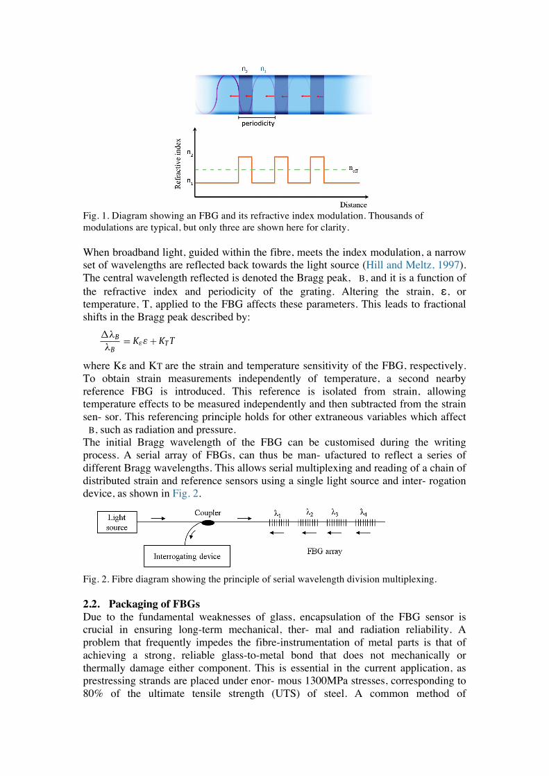
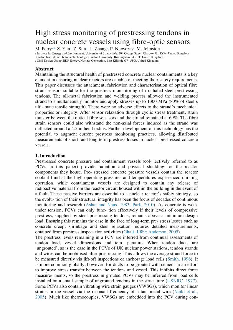
Fig. 1. Diagram showing an FBG and its refractive index modulation. Thousands of modulations are typical, but only three are shown here for clarity. When broadband light, guided within the fibre, meets the index modulation, a narrow set of wavelengths are reflected back towards the light source (Hill and Meltz, 1997). The central wavelength reflected is denoted the Bragg peak, !B, and it is a function of the refractive index and periodicity of the grating. Altering the strain, ε, or temperature, T, applied to the FBG affects these parameters. This leads to fractional shifts in the Bragg peak described by:
!! where Kε and KT are the strain and temperature sensitivity of the FBG, respectively. To obtain strain measurements independently of temperature, a second nearby reference FBG is introduced. This reference is isolated from strain, allowing temperature effects to be measured independently and then subtracted from the strain sen- sor. This referencing principle holds for other extraneous variables which affect !B, such as radiation and pressure. The initial Bragg wavelength of the FBG can be customised during the writing process. A serial array of FBGs, can thus be man- ufactured to reflect a series of different Bragg wavelengths. This allows serial multiplexing and reading of a chain of distributed strain and reference sensors using a single light source and inter- rogation device, as shown in Fig. 2.
Fig. 2. Fibre diagram showing the principle of serial wavelength division multiplexing. 2.2. Packaging of FBGs Due to the fundamental weaknesses of glass, encapsulation of the FBG sensor is crucial in ensuring long-term mechanical, ther- mal and radiation reliability. A problem that frequently impedes the fibre-instrumentation of metal parts is that of achieving a strong, reliable glass-to-metal bond that does not mechanically or thermally damage either component. This is essential in the current application, as prestressing strands are placed under enor- mous 1300MPa stresses, corresponding to 80% of the ultimate tensile strength (UTS) of steel. A common method of
36 M. Perry et al. / Nuclear Engineering and Design 268 (2014) 35– 40
cells installed on a small sample of ungrouted tendons in the struc-ture (USNRC, 1977). Some PCVs also contain vibrating wire straingauges (VWSGs), which monitor linear strains in the vessel via theresonant frequency of a taut metal wire (Neild et al., 2005). Muchlike thermocouples, VWSGs are embedded into the PCV during con-struction and so cannot be accessed later for repair or replacement.This places stringent requirements on the sensors’ reliability undercontinued radiation, temperature cycles and usage. This issue isespecially relevant to existing generation II reactors which containolder sensing technologies (McFarlane et al., 1997).
There is currently a strong interest in the nuclear power gen-eration industry to augment prestress monitoring practices, tofurther improve the safety of existing and future reactors. Themonitoring techniques above typically supply averaged measure-ments of tendon load with a 0.5 kN force resolution (equivalentto a strain of 10 !" in 7-wire strand). However, immediate pre-stress losses, such as friction between the tendon and duct; andslippage at tendon anchorages, lead to tendon forces which varyas a function of distance along the duct within the vessel (Nawy,2010). These spatially distributed tendon forces are not measuredby existing techniques, and knowledge of them is important forbuilding up an improved analysis of structural health in certainload cases.
Fibre optic sensors may provide a unique solution for auto-mated, distributed prestress monitoring, allowing the conversionof existing and future PCVs into smart structures (Udd, 1996). FibreBragg grating (FBG) sensors in particular, are well-suited to non-invasive integration into linear systems, like prestressing tendonstrands, due to their almost one-dimensional nature. Light weight,chemically inert, and immune to electromagnetic interference, FBGsensors detect changes in strain and temperature by measuring themodulated properties of light. As these point sensors can be seri-ally multiplexed, they can potentially form a highly cost-effectiveand extensible method for monitoring distributed strand strain.FBG strain sensor resolutions of 1 !" are common – indeed, someschemes with nanostrain resolutions have been proposed (Liu et al.,2010; Perry et al., 2012b). Fibre-instrumented strands may thusprovide a feasible method for acquiring new prestress informationwith a high resolution.
In this paper, we present an all-metal process for fabricatingand attaching FBG strain and temperature sensors to prestressingtendon strands. This allows us to demonstrate FBG sensors whichcan, for the first time, survive and monitor the strain in prestress-ing strands as they are stressed to 1300 MPa (80% of the strand’sultimate tensile strength). Furthermore, careful selection of fibreand packaging materials means these sensors are suitable for usein nuclear environments. The proposed ‘smart strand’ technology issuited to both new build PCVs with grouted or ungrouted ducts and,due to the fact that the strands can be mobilised and replaced, exist-ing ungrouted PCVs. By verifying and augmenting current healthmonitoring practices, this technology may improve confidence andsafety in not just current, but also future generations of nuclearpower plants.
2. Sensor design and fabrication
2.1. Fibre Bragg gratings
A fibre Bragg grating (FBG) is a periodic modulation of the refrac-tive index of an optical fibre, as shown in Fig. 1. The modulationis typically 5–20 mm long and is written by side illuminating aphotosensitive fibre with an ultraviolet laser.
When broadband light, guided within the fibre, meets the indexmodulation, a narrow set of wavelengths are reflected back towardsthe light source (Hill and Meltz, 1997). The central wavelengthreflected is denoted the Bragg peak, !B, and it is a function of the
Fig. 1. Diagram showing an FBG and its refractive index modulation. Thousands ofmodulations are typical, but only three are shown here for clarity.
refractive index and periodicity of the grating. Altering the strain,", or temperature, T, applied to the FBG affects these parameters.This leads to fractional shifts in the Bragg peak described by:
#!B
!B= K"" + KT T
where K" and KT are the strain and temperature sensitivity of theFBG, respectively. To obtain strain measurements independentlyof temperature, a second nearby reference FBG is introduced. Thisreference is isolated from strain, allowing temperature effects to bemeasured independently and then subtracted from the strain sen-sor. This referencing principle holds for other extraneous variableswhich affect !B, such as radiation and pressure.
The initial Bragg wavelength of the FBG can be customisedduring the writing process. A serial array of FBGs, can thus be man-ufactured to reflect a series of different Bragg wavelengths. Thisallows serial multiplexing and reading of a chain of distributedstrain and reference sensors using a single light source and inter-rogation device, as shown in Fig. 2.
2.2. Packaging of FBGs
Due to the fundamental weaknesses of glass, encapsulation ofthe FBG sensor is crucial in ensuring long-term mechanical, ther-mal and radiation reliability. A problem that frequently impedesthe fibre-instrumentation of metal parts is that of achieving astrong, reliable glass-to-metal bond that does not mechanicallyor thermally damage either component. This is essential in thecurrent application, as prestressing strands are placed under enor-mous 1300 MPa stresses, corresponding to 80% of the ultimatetensile strength (UTS) of steel. A common method of circumvent-ing the glass-to-metal bonding problem in strand instrumentationis to avoid using steel strands altogether (Li et al., 2004b). Opticalfibres can be more conveniently embedded or glued to fibre-reinforced plastic (FRP) prestressing strands, due to the material’slower hardness (Zhou and Sim, 2002). Unfortunately, the weakshear strength of FRPs and their enhanced degradation underirradiation, moisture, temperature and acidity make them lesssuited to the PCV environment (Chin et al., 1997). FRP strandsalso display different mechanical, thermal and relaxation proper-ties, making them unrepresentative of the existing steel strands inPCVs.
Given that steel strands must be used, another obviousglass bonding solution is epoxy. This is indeed a simple, room-temperature method, but the limited mechanical strength ofepoxies means attached sensors tend to fail before the 80% UTSthreshold is reached (Li et al., 2004a). Mechanical creep is also a
M. Perry et al. / Nuclear Engineering and Design 268 (2014) 35– 40 37
Fig. 2. Fibre diagram showing the principle of serial wavelength division multiplexing.
major problem once epoxies are stressed to beyond 50% of theirtensile strength (Majda and Skrodzewicz, 2009). This significantlyreduces a bonded strain sensor’s accuracy. Most epoxies are alsodegraded by radiation, and while novel radiation-resistant epoxieshave been developed, these display unacceptably low mechanicalstrengths (Prokopec et al., 2009).
To overcome the limitations of these conventional bondingmethods, we have developed an all-metal encapsulation andattachment process for FBG sensors. The exclusive use of metaljoining techniques helps to provide the thermal, mechanical andradiation resistance and diminished creep essential for long-termprestress monitoring (Beranek et al., 2001; Mei and Morris, 1992).In previous work, we characterised a high-temperature inductionbrazing process for encapsulating FBGs in metallic capillaries, with-out lasting thermal damage to the fibre (Perry et al., 2013). Thedesign of the packaged and welded FBG is shown in Fig. 3. As shown,the FBG is brazed into a capillary for mechanical protection underbending, tension and compression. Careful selection of the FBGs’glass and coating chemistry were used to ensure their long-termsurvivability under continued neutron-gamma radiation (Perryet al., 2012a; Gusarov and Hoeffgen, 2013), high temperatures(Canning, 2012) and large mechanical stresses (Kobrin, 1997). Duecare was also given to the fibre’s treatment and handling through-out the packaging process and this allowed the FBGs to retain thehigh tensile strength demanded by the application (Olshanksy andMaruer, 1976).
While brazing is suitable for packaging fibre sensors, expos-ing prestressing strands to high-temperatures can lead to strengthreduction and de-hardening of the steel. Furthermore, rapid coolingcan lead to martensite formation, causing the steel to become brittleand weak. To minimise strand damage, the packaged FBG sen-sors were attached using an electrical resistance spot welder. Thishighly localised welding method reduces the volumes of marten-sitic growth, which in turn minimises adverse thermal effects tothe steel’s mechanical properties. FBG strain sensors were weldedat both ends to allow strain to be transferred from the strandsto the FBG. Reference FBGs were welded at one end only, so thatthey could independently measure and correct for fluctuations inambient temperature.
Fig. 3. Diagram of a capillary-encapsulated fibre Bragg grating (FBG) attached to aprestressing strand.
3. Smart strand characterisation and results
3.1. Prestressing strand damage
To empirically verify the effects of spot-welding on a strand’sproperties, ten sensors were spot-welded to each of two strands,T1 and T2, while two control strands, T3 and T4, were left untreated.The strands were all placed under destructive tensile strength,metallographic and micro-hardness tests. As shown in Fig. 4, ten-sile tests until fracture revealed that the yield and ultimate tensilestrengths of all strands were higher than the values specified inBritish Standard BS 5896:1980. The modulus of elasticity of all spec-imens was 185 GPa, regardless of whether or not they were exposedto spot-welding.
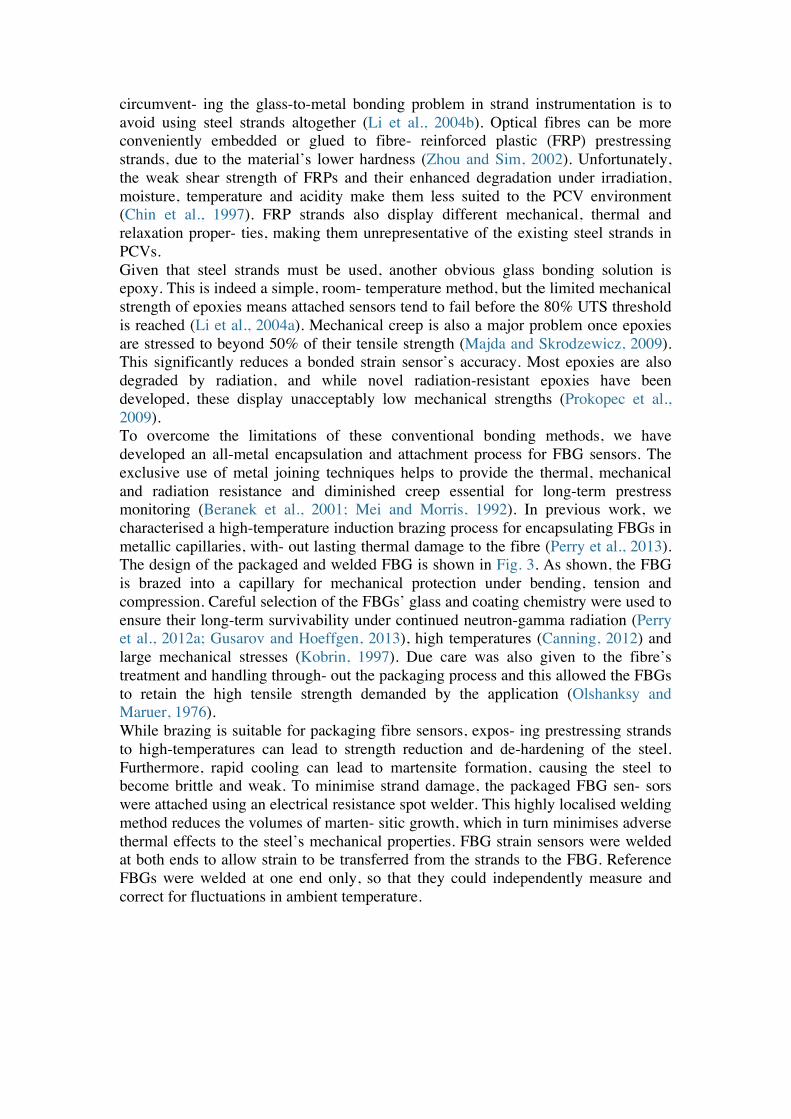
The mechanical hardness of both welded and non-weldedregions of the strands was tested using Vickers micro-indentationunder 300 g force. The 914 HV average hardness value found inwelded regions was almost double that of the unwelded regionsat 481 HV. This high hardness value demonstrates that martensitictransformations arose at weld locations due to rapid cooling. Togauge the extent of the martensite formation, cross-sections fromspot-welded regions of the strand were cut, polished and etchedto reveal the crystal microstructure. A typical optical microscopeimage is shown in Fig. 5. The images reveal that the martensitictransformations from spot-welding only penetrate approximately0.1 mm from the strand surface. The strand’s mechanical propertieswere unaffected because of this minimal damage.
3.2. Temperature characterisation
Because the coefficient of thermal expansion of glass fibre islow, the temperature sensitivity of unbonded, reference FBGs ismainly dependent on thermally induced refractive index changes.The thermal sensitivity of the welded FBG strain sensor, on theother hand, is heavily influenced by the thermal expansion of thesteel strand to which it is attached.
Fig. 4. Comparison of ultimate tensile and yield strength of spot-welded (T1 andT2) and untreated (T3 and T4) strand specimens.
circumvent- ing the glass-to-metal bonding problem in strand instrumentation is to avoid using steel strands altogether (Li et al., 2004b). Optical fibres can be more conveniently embedded or glued to fibre- reinforced plastic (FRP) prestressing strands, due to the material’s lower hardness (Zhou and Sim, 2002). Unfortunately, the weak shear strength of FRPs and their enhanced degradation under irradiation, moisture, temperature and acidity make them less suited to the PCV environment (Chin et al., 1997). FRP strands also display different mechanical, thermal and relaxation proper- ties, making them unrepresentative of the existing steel strands in PCVs. Given that steel strands must be used, another obvious glass bonding solution is epoxy. This is indeed a simple, room- temperature method, but the limited mechanical strength of epoxies means attached sensors tend to fail before the 80% UTS threshold is reached (Li et al., 2004a). Mechanical creep is also a major problem once epoxies are stressed to beyond 50% of their tensile strength (Majda and Skrodzewicz, 2009). This significantly reduces a bonded strain sensor’s accuracy. Most epoxies are also degraded by radiation, and while novel radiation-resistant epoxies have been developed, these display unacceptably low mechanical strengths (Prokopec et al., 2009). To overcome the limitations of these conventional bonding methods, we have developed an all-metal encapsulation and attachment process for FBG sensors. The exclusive use of metal joining techniques helps to provide the thermal, mechanical and radiation resistance and diminished creep essential for long-term prestress monitoring (Beranek et al., 2001; Mei and Morris, 1992). In previous work, we characterised a high-temperature induction brazing process for encapsulating FBGs in metallic capillaries, with- out lasting thermal damage to the fibre (Perry et al., 2013). The design of the packaged and welded FBG is shown in Fig. 3. As shown, the FBG is brazed into a capillary for mechanical protection under bending, tension and compression. Careful selection of the FBGs’ glass and coating chemistry were used to ensure their long-term survivability under continued neutron-gamma radiation (Perry et al., 2012a; Gusarov and Hoeffgen, 2013), high temperatures (Canning, 2012) and large mechanical stresses (Kobrin, 1997). Due care was also given to the fibre’s treatment and handling through- out the packaging process and this allowed the FBGs to retain the high tensile strength demanded by the application (Olshanksy and Maruer, 1976). While brazing is suitable for packaging fibre sensors, expos- ing prestressing strands to high-temperatures can lead to strength reduction and de-hardening of the steel. Furthermore, rapid cooling can lead to martensite formation, causing the steel to become brittle and weak. To minimise strand damage, the packaged FBG sen- sors were attached using an electrical resistance spot welder. This highly localised welding method reduces the volumes of marten- sitic growth, which in turn minimises adverse thermal effects to the steel’s mechanical properties. FBG strain sensors were welded at both ends to allow strain to be transferred from the strands to the FBG. Reference FBGs were welded at one end only, so that they could independently measure and correct for fluctuations in ambient temperature.

Fig. 3. Diagram of a capillary-encapsulated fibre Bragg grating (FBG) attached to a
prestressing strand 3. Smart strand characterisation and results 3.1. Prestressing strand damage To empirically verify the effects of spot-welding on a strand’s properties, ten sensors were spot-welded to each of two strands, T1 and T2, while two control strands, T3 and T4, were left untreated. The strands were all placed under destructive tensile strength, metallographic and micro-hardness tests. As shown in Fig. 4, ten- sile tests until fracture revealed that the yield and ultimate tensile strengths of all strands were higher than the values specified in British Standard BS 5896:1980. The modulus of elasticity of all spec- imens was 185 GPa, regardless of whether or not they were exposed to spot-welding.
Fig. 4. Comparison of ultimate tensile and yield strength of spot-welded (T1 and T2) and
untreated (T3 and T4) strand specimens.
The mechanical hardness of both welded and non-welded regions of the strands was tested using Vickers micro-indentation under 300g force. The 914 HV average hardness value found in welded regions was almost double that of the unwelded regions at 481 HV. This high hardness value demonstrates that martensitic transformations arose at weld locations due to rapid cooling. To gauge the extent of the martensite formation, cross-sections from spot-welded regions of the strand were cut, polished and etched to reveal the crystal microstructure. A typical optical microscope image is shown in Fig. 5. The images reveal that the martensitic transformations from spot-welding only penetrate approximately 0.1 mm from the strand surface. The strand’s mechanical properties were unaffected because of this minimal damage.
M. Perry et al. / Nuclear Engineering and Design 268 (2014) 35– 40 37
Fig. 2. Fibre diagram showing the principle of serial wavelength division multiplexing.
major problem once epoxies are stressed to beyond 50% of theirtensile strength (Majda and Skrodzewicz, 2009). This significantlyreduces a bonded strain sensor’s accuracy. Most epoxies are alsodegraded by radiation, and while novel radiation-resistant epoxieshave been developed, these display unacceptably low mechanicalstrengths (Prokopec et al., 2009).
To overcome the limitations of these conventional bondingmethods, we have developed an all-metal encapsulation andattachment process for FBG sensors. The exclusive use of metaljoining techniques helps to provide the thermal, mechanical andradiation resistance and diminished creep essential for long-termprestress monitoring (Beranek et al., 2001; Mei and Morris, 1992).In previous work, we characterised a high-temperature inductionbrazing process for encapsulating FBGs in metallic capillaries, with-out lasting thermal damage to the fibre (Perry et al., 2013). Thedesign of the packaged and welded FBG is shown in Fig. 3. As shown,the FBG is brazed into a capillary for mechanical protection underbending, tension and compression. Careful selection of the FBGs’glass and coating chemistry were used to ensure their long-termsurvivability under continued neutron-gamma radiation (Perryet al., 2012a; Gusarov and Hoeffgen, 2013), high temperatures(Canning, 2012) and large mechanical stresses (Kobrin, 1997). Duecare was also given to the fibre’s treatment and handling through-out the packaging process and this allowed the FBGs to retain thehigh tensile strength demanded by the application (Olshanksy andMaruer, 1976).
While brazing is suitable for packaging fibre sensors, expos-ing prestressing strands to high-temperatures can lead to strengthreduction and de-hardening of the steel. Furthermore, rapid coolingcan lead to martensite formation, causing the steel to become brittleand weak. To minimise strand damage, the packaged FBG sen-sors were attached using an electrical resistance spot welder. Thishighly localised welding method reduces the volumes of marten-sitic growth, which in turn minimises adverse thermal effects tothe steel’s mechanical properties. FBG strain sensors were weldedat both ends to allow strain to be transferred from the strandsto the FBG. Reference FBGs were welded at one end only, so thatthey could independently measure and correct for fluctuations inambient temperature.
Fig. 3. Diagram of a capillary-encapsulated fibre Bragg grating (FBG) attached to aprestressing strand.
3. Smart strand characterisation and results
3.1. Prestressing strand damage
To empirically verify the effects of spot-welding on a strand’sproperties, ten sensors were spot-welded to each of two strands,T1 and T2, while two control strands, T3 and T4, were left untreated.The strands were all placed under destructive tensile strength,metallographic and micro-hardness tests. As shown in Fig. 4, ten-sile tests until fracture revealed that the yield and ultimate tensilestrengths of all strands were higher than the values specified inBritish Standard BS 5896:1980. The modulus of elasticity of all spec-imens was 185 GPa, regardless of whether or not they were exposedto spot-welding.
The mechanical hardness of both welded and non-weldedregions of the strands was tested using Vickers micro-indentationunder 300 g force. The 914 HV average hardness value found inwelded regions was almost double that of the unwelded regionsat 481 HV. This high hardness value demonstrates that martensitictransformations arose at weld locations due to rapid cooling. Togauge the extent of the martensite formation, cross-sections fromspot-welded regions of the strand were cut, polished and etchedto reveal the crystal microstructure. A typical optical microscopeimage is shown in Fig. 5. The images reveal that the martensitictransformations from spot-welding only penetrate approximately0.1 mm from the strand surface. The strand’s mechanical propertieswere unaffected because of this minimal damage.
3.2. Temperature characterisation
Because the coefficient of thermal expansion of glass fibre islow, the temperature sensitivity of unbonded, reference FBGs ismainly dependent on thermally induced refractive index changes.The thermal sensitivity of the welded FBG strain sensor, on theother hand, is heavily influenced by the thermal expansion of thesteel strand to which it is attached.
Fig. 4. Comparison of ultimate tensile and yield strength of spot-welded (T1 andT2) and untreated (T3 and T4) strand specimens.
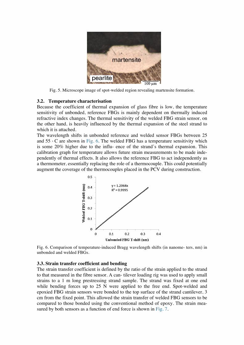
Fig. 5. Microscope image of spot-welded region revealing martensite formation.
3.2. Temperature characterisation Because the coefficient of thermal expansion of glass fibre is low, the temperature sensitivity of unbonded, reference FBGs is mainly dependent on thermally induced refractive index changes. The thermal sensitivity of the welded FBG strain sensor, on the other hand, is heavily influenced by the thermal expansion of the steel strand to which it is attached. The wavelength shifts in unbonded reference and welded sensor FBGs between 25 and 55 ◦ C are shown in Fig. 6. The welded FBG has a temperature sensitivity which is some 20% higher due to the influ- ence of the strand’s thermal expansion. This calibration graph for temperature allows future strain measurements to be made inde- pendently of thermal effects. It also allows the reference FBG to act independently as a thermometer, essentially replacing the role of a thermocouple. This could potentially augment the coverage of the thermocouples placed in the PCV during construction.
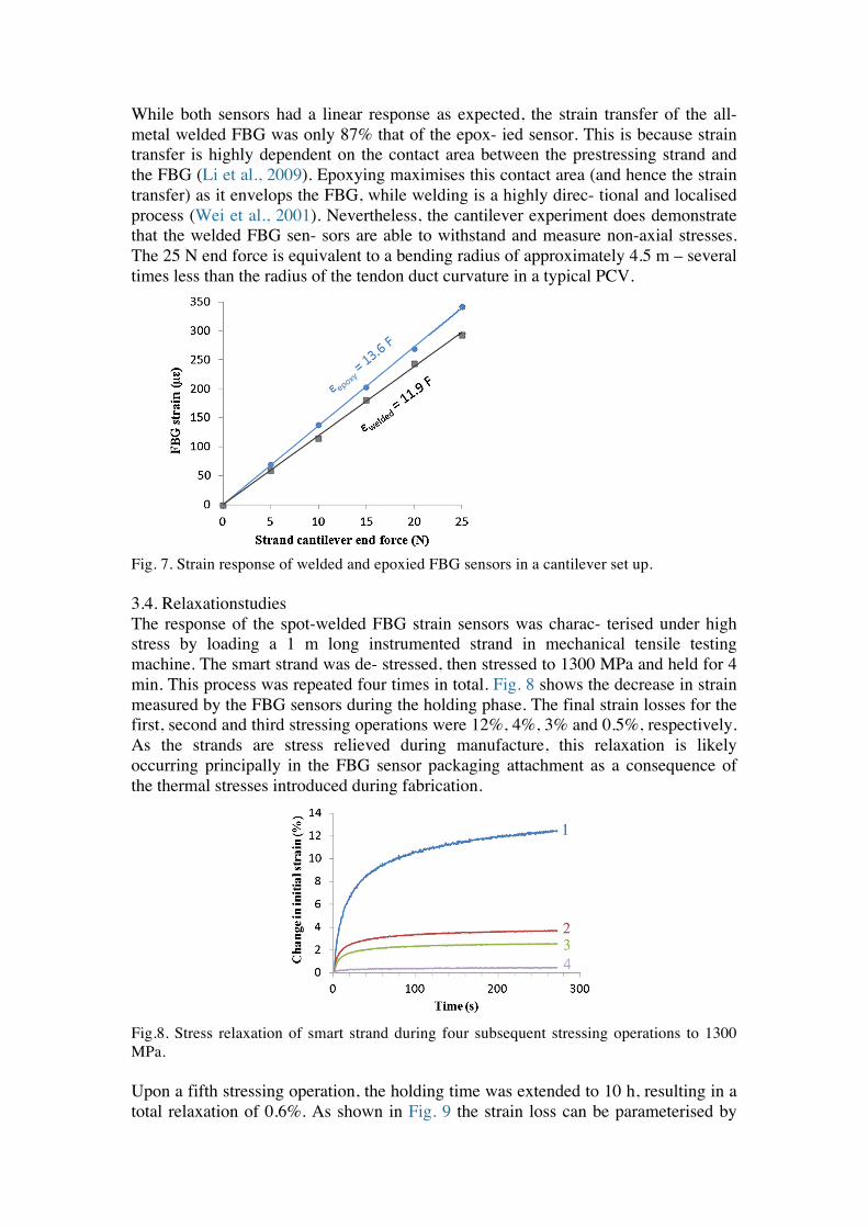
Fig. 6. Comparison of temperature-induced Bragg wavelength shifts (in nanome- ters, nm) in unbonded and welded FBGs. 3.3. Strain transfer coefficient and bending The strain transfer coefficient is defined by the ratio of the strain applied to the strand to that measured in the fibre sensor. A can- tilever loading rig was used to apply small strains to a 1 m long prestressing strand sample. The strand was fixed at one end while bending forces up to 25 N were applied to the free end. Spot-welded and epoxied FBG strain sensors were bonded to the top surface of the strand cantilever, 3 cm from the fixed point. This allowed the strain transfer of welded FBG sensors to be compared to those bonded using the conventional method of epoxy. The strain mea- sured by both sensors as a function of end force is shown in Fig. 7.
38 M. Perry et al. / Nuclear Engineering and Design 268 (2014) 35– 40
Fig. 5. Microscope image of spot-welded region revealing martensite formation.
The wavelength shifts in unbonded reference and welded sensorFBGs between 25 and 55 !C are shown in Fig. 6. The welded FBG hasa temperature sensitivity which is some 20% higher due to the influ-ence of the strand’s thermal expansion. This calibration graph fortemperature allows future strain measurements to be made inde-pendently of thermal effects. It also allows the reference FBG to actindependently as a thermometer, essentially replacing the role of athermocouple. This could potentially augment the coverage of thethermocouples placed in the PCV during construction.
3.3. Strain transfer coefficient and bending
The strain transfer coefficient is defined by the ratio of the strainapplied to the strand to that measured in the fibre sensor. A can-tilever loading rig was used to apply small strains to a 1 m longprestressing strand sample. The strand was fixed at one end whilebending forces up to 25 N were applied to the free end. Spot-weldedand epoxied FBG strain sensors were bonded to the top surfaceof the strand cantilever, 3 cm from the fixed point. This allowedthe strain transfer of welded FBG sensors to be compared to thosebonded using the conventional method of epoxy. The strain mea-sured by both sensors as a function of end force is shown in Fig. 7.
While both sensors had a linear response as expected, the straintransfer of the all-metal welded FBG was only 87% that of the epox-ied sensor. This is because strain transfer is highly dependent on thecontact area between the prestressing strand and the FBG (Li et al.,2009). Epoxying maximises this contact area (and hence the straintransfer) as it envelops the FBG, while welding is a highly direc-tional and localised process (Wei et al., 2001). Nevertheless, thecantilever experiment does demonstrate that the welded FBG sen-sors are able to withstand and measure non-axial stresses. The 25 N
Fig. 6. Comparison of temperature-induced Bragg wavelength shifts (in nanome-ters, nm) in unbonded and welded FBGs.
Fig. 7. Strain response of welded and epoxied FBG sensors in a cantilever set up.
end force is equivalent to a bending radius of approximately 4.5 m– several times less than the radius of the tendon duct curvature ina typical PCV.
3.4. Relaxation studies
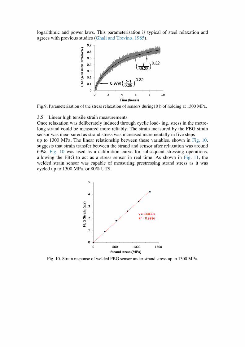
The response of the spot-welded FBG strain sensors was charac-terised under high stress by loading a 1 m long instrumented strandin mechanical tensile testing machine. The smart strand was de-stressed, then stressed to 1300 MPa and held for 4 min. This processwas repeated four times in total. Fig. 8 shows the decrease in strainmeasured by the FBG sensors during the holding phase. The finalstrain losses for the first, second and third stressing operations were12%, 4%, 3% and 0.5%, respectively. As the strands are stress relievedduring manufacture, this relaxation is likely occurring principallyin the FBG sensor packaging attachment as a consequence of thethermal stresses introduced during fabrication.
Upon a fifth stressing operation, the holding time was extendedto 10 h, resulting in a total relaxation of 0.6%. As shown in Fig. 9 thestrain loss can be parameterised by logarithmic and power laws.This parameterisation is typical of steel relaxation and agrees withprevious studies (Ghali and Trevino, 1985).
3.5. Linear high tensile strain measurements
Once relaxation was deliberately induced through cyclic load-ing, stress in the metre-long strand could be measured morereliably. The strain measured by the FBG strain sensor was mea-sured as strand stress was increased incrementally in five steps
Fig. 8. Stress relaxation of smart strand during four subsequent stressing operationsto 1300 MPa.
38 M. Perry et al. / Nuclear Engineering and Design 268 (2014) 35– 40
Fig. 5. Microscope image of spot-welded region revealing martensite formation.
The wavelength shifts in unbonded reference and welded sensorFBGs between 25 and 55 !C are shown in Fig. 6. The welded FBG hasa temperature sensitivity which is some 20% higher due to the influ-ence of the strand’s thermal expansion. This calibration graph fortemperature allows future strain measurements to be made inde-pendently of thermal effects. It also allows the reference FBG to actindependently as a thermometer, essentially replacing the role of athermocouple. This could potentially augment the coverage of thethermocouples placed in the PCV during construction.
3.3. Strain transfer coefficient and bending
The strain transfer coefficient is defined by the ratio of the strainapplied to the strand to that measured in the fibre sensor. A can-tilever loading rig was used to apply small strains to a 1 m longprestressing strand sample. The strand was fixed at one end whilebending forces up to 25 N were applied to the free end. Spot-weldedand epoxied FBG strain sensors were bonded to the top surfaceof the strand cantilever, 3 cm from the fixed point. This allowedthe strain transfer of welded FBG sensors to be compared to thosebonded using the conventional method of epoxy. The strain mea-sured by both sensors as a function of end force is shown in Fig. 7.
While both sensors had a linear response as expected, the straintransfer of the all-metal welded FBG was only 87% that of the epox-ied sensor. This is because strain transfer is highly dependent on thecontact area between the prestressing strand and the FBG (Li et al.,2009). Epoxying maximises this contact area (and hence the straintransfer) as it envelops the FBG, while welding is a highly direc-tional and localised process (Wei et al., 2001). Nevertheless, thecantilever experiment does demonstrate that the welded FBG sen-sors are able to withstand and measure non-axial stresses. The 25 N
Fig. 6. Comparison of temperature-induced Bragg wavelength shifts (in nanome-ters, nm) in unbonded and welded FBGs.
Fig. 7. Strain response of welded and epoxied FBG sensors in a cantilever set up.
end force is equivalent to a bending radius of approximately 4.5 m– several times less than the radius of the tendon duct curvature ina typical PCV.
3.4. Relaxation studies
The response of the spot-welded FBG strain sensors was charac-terised under high stress by loading a 1 m long instrumented strandin mechanical tensile testing machine. The smart strand was de-stressed, then stressed to 1300 MPa and held for 4 min. This processwas repeated four times in total. Fig. 8 shows the decrease in strainmeasured by the FBG sensors during the holding phase. The finalstrain losses for the first, second and third stressing operations were12%, 4%, 3% and 0.5%, respectively. As the strands are stress relievedduring manufacture, this relaxation is likely occurring principallyin the FBG sensor packaging attachment as a consequence of thethermal stresses introduced during fabrication.
Upon a fifth stressing operation, the holding time was extendedto 10 h, resulting in a total relaxation of 0.6%. As shown in Fig. 9 thestrain loss can be parameterised by logarithmic and power laws.This parameterisation is typical of steel relaxation and agrees withprevious studies (Ghali and Trevino, 1985).
3.5. Linear high tensile strain measurements
Once relaxation was deliberately induced through cyclic load-ing, stress in the metre-long strand could be measured morereliably. The strain measured by the FBG strain sensor was mea-sured as strand stress was increased incrementally in five steps
Fig. 8. Stress relaxation of smart strand during four subsequent stressing operationsto 1300 MPa.
While both sensors had a linear response as expected, the strain transfer of the all-metal welded FBG was only 87% that of the epox- ied sensor. This is because strain transfer is highly dependent on the contact area between the prestressing strand and the FBG (Li et al., 2009). Epoxying maximises this contact area (and hence the strain transfer) as it envelops the FBG, while welding is a highly direc- tional and localised process (Wei et al., 2001). Nevertheless, the cantilever experiment does demonstrate that the welded FBG sen- sors are able to withstand and measure non-axial stresses. The 25 N end force is equivalent to a bending radius of approximately 4.5 m – several times less than the radius of the tendon duct curvature in a typical PCV.
Fig. 7. Strain response of welded and epoxied FBG sensors in a cantilever set up. 3.4. Relaxationstudies The response of the spot-welded FBG strain sensors was charac- terised under high stress by loading a 1 m long instrumented strand in mechanical tensile testing machine. The smart strand was de- stressed, then stressed to 1300 MPa and held for 4 min. This process was repeated four times in total. Fig. 8 shows the decrease in strain measured by the FBG sensors during the holding phase. The final strain losses for the first, second and third stressing operations were 12%, 4%, 3% and 0.5%, respectively. As the strands are stress relieved during manufacture, this relaxation is likely occurring principally in the FBG sensor packaging attachment as a consequence of the thermal stresses introduced during fabrication.
Fig.8. Stress relaxation of smart strand during four subsequent stressing operations to 1300 MPa. Upon a fifth stressing operation, the holding time was extended to 10 h, resulting in a total relaxation of 0.6%. As shown in Fig. 9 the strain loss can be parameterised by
38 M. Perry et al. / Nuclear Engineering and Design 268 (2014) 35– 40
Fig. 5. Microscope image of spot-welded region revealing martensite formation.
The wavelength shifts in unbonded reference and welded sensorFBGs between 25 and 55 !C are shown in Fig. 6. The welded FBG hasa temperature sensitivity which is some 20% higher due to the influ-ence of the strand’s thermal expansion. This calibration graph fortemperature allows future strain measurements to be made inde-pendently of thermal effects. It also allows the reference FBG to actindependently as a thermometer, essentially replacing the role of athermocouple. This could potentially augment the coverage of thethermocouples placed in the PCV during construction.
3.3. Strain transfer coefficient and bending
The strain transfer coefficient is defined by the ratio of the strainapplied to the strand to that measured in the fibre sensor. A can-tilever loading rig was used to apply small strains to a 1 m longprestressing strand sample. The strand was fixed at one end whilebending forces up to 25 N were applied to the free end. Spot-weldedand epoxied FBG strain sensors were bonded to the top surfaceof the strand cantilever, 3 cm from the fixed point. This allowedthe strain transfer of welded FBG sensors to be compared to thosebonded using the conventional method of epoxy. The strain mea-sured by both sensors as a function of end force is shown in Fig. 7.
While both sensors had a linear response as expected, the straintransfer of the all-metal welded FBG was only 87% that of the epox-ied sensor. This is because strain transfer is highly dependent on thecontact area between the prestressing strand and the FBG (Li et al.,2009). Epoxying maximises this contact area (and hence the straintransfer) as it envelops the FBG, while welding is a highly direc-tional and localised process (Wei et al., 2001). Nevertheless, thecantilever experiment does demonstrate that the welded FBG sen-sors are able to withstand and measure non-axial stresses. The 25 N
Fig. 6. Comparison of temperature-induced Bragg wavelength shifts (in nanome-ters, nm) in unbonded and welded FBGs.
Fig. 7. Strain response of welded and epoxied FBG sensors in a cantilever set up.
end force is equivalent to a bending radius of approximately 4.5 m– several times less than the radius of the tendon duct curvature ina typical PCV.
3.4. Relaxation studies
The response of the spot-welded FBG strain sensors was charac-terised under high stress by loading a 1 m long instrumented strandin mechanical tensile testing machine. The smart strand was de-stressed, then stressed to 1300 MPa and held for 4 min. This processwas repeated four times in total. Fig. 8 shows the decrease in strainmeasured by the FBG sensors during the holding phase. The finalstrain losses for the first, second and third stressing operations were12%, 4%, 3% and 0.5%, respectively. As the strands are stress relievedduring manufacture, this relaxation is likely occurring principallyin the FBG sensor packaging attachment as a consequence of thethermal stresses introduced during fabrication.
Upon a fifth stressing operation, the holding time was extendedto 10 h, resulting in a total relaxation of 0.6%. As shown in Fig. 9 thestrain loss can be parameterised by logarithmic and power laws.This parameterisation is typical of steel relaxation and agrees withprevious studies (Ghali and Trevino, 1985).
3.5. Linear high tensile strain measurements
Once relaxation was deliberately induced through cyclic load-ing, stress in the metre-long strand could be measured morereliably. The strain measured by the FBG strain sensor was mea-sured as strand stress was increased incrementally in five steps
Fig. 8. Stress relaxation of smart strand during four subsequent stressing operationsto 1300 MPa.
logarithmic and power laws. This parameterisation is typical of steel relaxation and agrees with previous studies (Ghali and Trevino, 1985).
Fig.9. Parameterisation of the stress relaxation of sensors during10 h of holding at 1300 MPa.
3.5. Linear high tensile strain measurements Once relaxation was deliberately induced through cyclic load- ing, stress in the metre-long strand could be measured more reliably. The strain measured by the FBG strain sensor was mea- sured as strand stress was increased incrementally in five steps up to 1300 MPa. The linear relationship between these variables, shown in Fig. 10, suggests that strain transfer between the strand and sensor after relaxation was around 69%. Fig. 10 was used as a calibration curve for subsequent stressing operations, allowing the FBG to act as a stress sensor in real time. As shown in Fig. 11, the welded strain sensor was capable of measuring prestressing strand stress as it was cycled up to 1300 MPa, or 80% UTS.
Fig. 10. Strain response of welded FBG sensor under strand stress up to 1300 MPa.
M. Perry et al. / Nuclear Engineering and Design 268 (2014) 35– 40 39
Fig. 9. Parameterisation of the stress relaxation of sensors during 10 h of holding at1300 MPa.
Fig. 10. Strain response of welded FBG sensor under strand stress up to 1300 MPa.
up to 1300 MPa. The linear relationship between these variables,shown in Fig. 10, suggests that strain transfer between the strandand sensor after relaxation was around 69%. Fig. 10 was used as acalibration curve for subsequent stressing operations, allowing theFBG to act as a stress sensor in real time. As shown in Fig. 11, thewelded strain sensor was capable of measuring prestressing strandstress as it was cycled up to 1300 MPa, or 80% UTS.
Fig. 11. Calibrated FBG strain sensor measuring stress as strand cycled between 0%and 80% UTS.
4. Discussion and future work
The work here has shown that radiation-resistant FBG strainsensors can survive and measure the stress in prestressing strandsup to 80% UTS. Crucially, the attachment of the sensors does notaffect strand integrity. This means that conventional steel pre-stressing strands can be used as a sensing medium – allowing thestrands to uphold structural health while simultaneously moni-toring it. The strain transfer between the strand and sensors wasaround 69%, slightly reduced due to relaxation and the directionalnature of spot-welding. Lower strain transfer values may in fact bebeneficial as they limit the strain applied to the FBGs, reducing thechances of fibre failure.
Due to the modular nature of the FBG sensors presented here,scaling the proposed smart strand technology up to real PCV pre-stress monitoring applications may be relatively straightforwardand cost-effective. Sensors could, in future, be attached during orbefore strand replacement activities, from a reel of prepared fibresensors. A combination of wavelength division multiplexing andparallel fibre lines will allow a single optical interrogator to monitornumerous strands within the PCV with a high level of redundancy.This redundancy may be essential, as monitoring strand stress inde-pendently of bend and wire slippage will require multiple strainsensors.
The results from lab demonstrations presented here encouragefurther investigation. Before field tests in model structures are con-ducted, further studies are required to characterise the dependenceof relaxation on the materials and processing of the FBG strain sen-sor. Cyclic stressing of the sensor packaging before attachment mayreduce relaxation, allowing the smart strand to begin functioningimmediately upon its initial prestressing. Relaxation may also beenhanced under radiation, so long-term irradiation studies will berequired to empirically prove that the proposed smart strand canmeasure stress reliably in PCVs, though most tendons experienceminimal radiation doses. Characterisation of the strain measuredat different ambient temperatures may also be required as FBGstrain sensitivity can be temperature dependent (O’Dwyer et al.,2004). Finally, making sensor fabrication and attachment methodsautomated will allow the strain and temperature sensitivity to bepredicted and characterised more reliably, enhancing the system’sperformance in industrial applications.
While the strain transfer of the spot-welded sensors is slightlyless than that of epoxies, the final adopted technique has demon-strated sensors with a much higher strain range. Obtaining thesebenefits requires more intensive manufacturing processes, but thefact that the fibre sensors can continue to withstand and mea-sure high strains after processing is an indication that the hightemperature processing has not caused adverse thermal damage.Furthermore, as the sensors’ packaging and bonding mechanismsare completely metallic, they are less likely to be susceptible toradiation damage, but future work will be required to prove thisexplicitly.
There are other aspects of this technology which will requireaddressing before the smart strand can be fully commercialised.For example, there is potential for mechanical damage of the glassfibres during their installation into real structures as a consequenceof mishandling, misalignment, pinching or bending, particularly atthe tendon anchorages as they are inserted into the PCV. Theseissues will require detailed consideration of current tendon instal-lation procedures and perhaps design changes to allow the fibresto meet the physical demands of installation.
Note that while the smart strand may be a viable method ofmeasuring the majority of strain-inducing prestress losses, it can-not measure those losses which do not induce strain, such as strandrelaxation. As strand relaxation is a relatively large effect in newstrands, it can be measured with conventional methods, such as
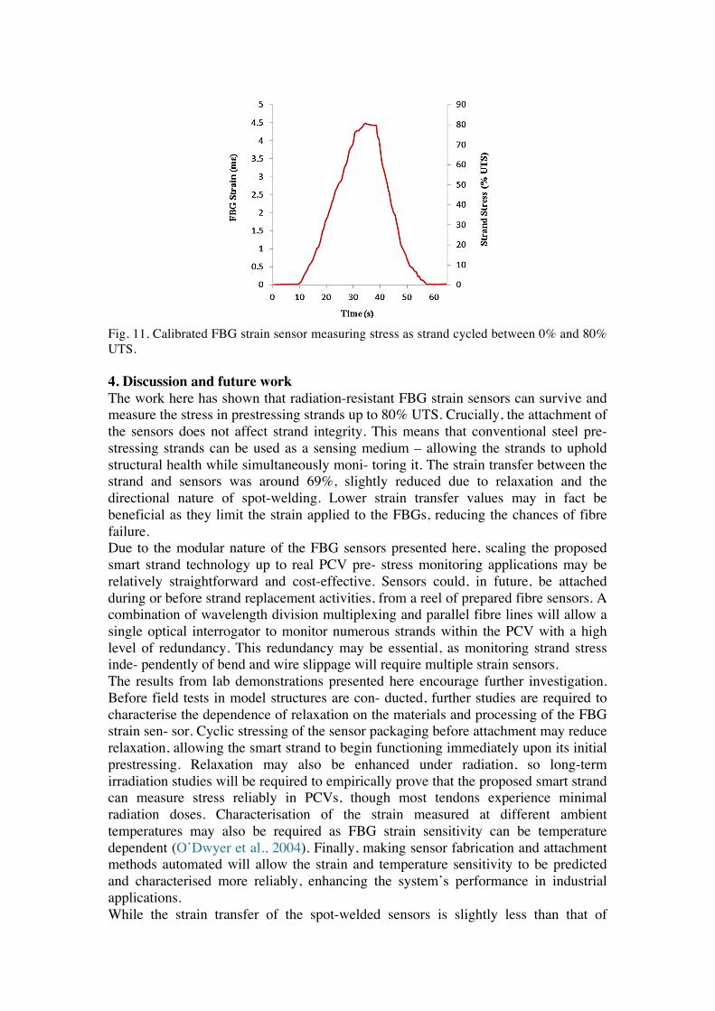
Fig. 11. Calibrated FBG strain sensor measuring stress as strand cycled between 0% and 80% UTS. 4. Discussion and future work The work here has shown that radiation-resistant FBG strain sensors can survive and measure the stress in prestressing strands up to 80% UTS. Crucially, the attachment of the sensors does not affect strand integrity. This means that conventional steel pre- stressing strands can be used as a sensing medium – allowing the strands to uphold structural health while simultaneously moni- toring it. The strain transfer between the strand and sensors was around 69%, slightly reduced due to relaxation and the directional nature of spot-welding. Lower strain transfer values may in fact be beneficial as they limit the strain applied to the FBGs, reducing the chances of fibre failure. Due to the modular nature of the FBG sensors presented here, scaling the proposed smart strand technology up to real PCV pre- stress monitoring applications may be relatively straightforward and cost-effective. Sensors could, in future, be attached during or before strand replacement activities, from a reel of prepared fibre sensors. A combination of wavelength division multiplexing and parallel fibre lines will allow a single optical interrogator to monitor numerous strands within the PCV with a high level of redundancy. This redundancy may be essential, as monitoring strand stress inde- pendently of bend and wire slippage will require multiple strain sensors. The results from lab demonstrations presented here encourage further investigation. Before field tests in model structures are con- ducted, further studies are required to characterise the dependence of relaxation on the materials and processing of the FBG strain sen- sor. Cyclic stressing of the sensor packaging before attachment may reduce relaxation, allowing the smart strand to begin functioning immediately upon its initial prestressing. Relaxation may also be enhanced under radiation, so long-term irradiation studies will be required to empirically prove that the proposed smart strand can measure stress reliably in PCVs, though most tendons experience minimal radiation doses. Characterisation of the strain measured at different ambient temperatures may also be required as FBG strain sensitivity can be temperature dependent (O’Dwyer et al., 2004). Finally, making sensor fabrication and attachment methods automated will allow the strain and temperature sensitivity to be predicted and characterised more reliably, enhancing the system’s performance in industrial applications. While the strain transfer of the spot-welded sensors is slightly less than that of
M. Perry et al. / Nuclear Engineering and Design 268 (2014) 35– 40 39
Fig. 9. Parameterisation of the stress relaxation of sensors during 10 h of holding at1300 MPa.
Fig. 10. Strain response of welded FBG sensor under strand stress up to 1300 MPa.
up to 1300 MPa. The linear relationship between these variables,shown in Fig. 10, suggests that strain transfer between the strandand sensor after relaxation was around 69%. Fig. 10 was used as acalibration curve for subsequent stressing operations, allowing theFBG to act as a stress sensor in real time. As shown in Fig. 11, thewelded strain sensor was capable of measuring prestressing strandstress as it was cycled up to 1300 MPa, or 80% UTS.
Fig. 11. Calibrated FBG strain sensor measuring stress as strand cycled between 0%and 80% UTS.
4. Discussion and future work
The work here has shown that radiation-resistant FBG strainsensors can survive and measure the stress in prestressing strandsup to 80% UTS. Crucially, the attachment of the sensors does notaffect strand integrity. This means that conventional steel pre-stressing strands can be used as a sensing medium – allowing thestrands to uphold structural health while simultaneously moni-toring it. The strain transfer between the strand and sensors wasaround 69%, slightly reduced due to relaxation and the directionalnature of spot-welding. Lower strain transfer values may in fact bebeneficial as they limit the strain applied to the FBGs, reducing thechances of fibre failure.
Due to the modular nature of the FBG sensors presented here,scaling the proposed smart strand technology up to real PCV pre-stress monitoring applications may be relatively straightforwardand cost-effective. Sensors could, in future, be attached during orbefore strand replacement activities, from a reel of prepared fibresensors. A combination of wavelength division multiplexing andparallel fibre lines will allow a single optical interrogator to monitornumerous strands within the PCV with a high level of redundancy.This redundancy may be essential, as monitoring strand stress inde-pendently of bend and wire slippage will require multiple strainsensors.
The results from lab demonstrations presented here encouragefurther investigation. Before field tests in model structures are con-ducted, further studies are required to characterise the dependenceof relaxation on the materials and processing of the FBG strain sen-sor. Cyclic stressing of the sensor packaging before attachment mayreduce relaxation, allowing the smart strand to begin functioningimmediately upon its initial prestressing. Relaxation may also beenhanced under radiation, so long-term irradiation studies will berequired to empirically prove that the proposed smart strand canmeasure stress reliably in PCVs, though most tendons experienceminimal radiation doses. Characterisation of the strain measuredat different ambient temperatures may also be required as FBGstrain sensitivity can be temperature dependent (O’Dwyer et al.,2004). Finally, making sensor fabrication and attachment methodsautomated will allow the strain and temperature sensitivity to bepredicted and characterised more reliably, enhancing the system’sperformance in industrial applications.
While the strain transfer of the spot-welded sensors is slightlyless than that of epoxies, the final adopted technique has demon-strated sensors with a much higher strain range. Obtaining thesebenefits requires more intensive manufacturing processes, but thefact that the fibre sensors can continue to withstand and mea-sure high strains after processing is an indication that the hightemperature processing has not caused adverse thermal damage.Furthermore, as the sensors’ packaging and bonding mechanismsare completely metallic, they are less likely to be susceptible toradiation damage, but future work will be required to prove thisexplicitly.
There are other aspects of this technology which will requireaddressing before the smart strand can be fully commercialised.For example, there is potential for mechanical damage of the glassfibres during their installation into real structures as a consequenceof mishandling, misalignment, pinching or bending, particularly atthe tendon anchorages as they are inserted into the PCV. Theseissues will require detailed consideration of current tendon instal-lation procedures and perhaps design changes to allow the fibresto meet the physical demands of installation.
Note that while the smart strand may be a viable method ofmeasuring the majority of strain-inducing prestress losses, it can-not measure those losses which do not induce strain, such as strandrelaxation. As strand relaxation is a relatively large effect in newstrands, it can be measured with conventional methods, such as
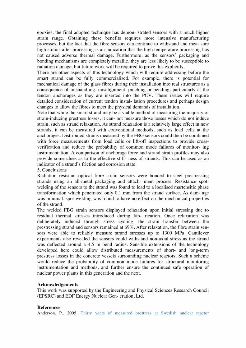
epoxies, the final adopted technique has demon- strated sensors with a much higher strain range. Obtaining these benefits requires more intensive manufacturing processes, but the fact that the fibre sensors can continue to withstand and mea- sure high strains after processing is an indication that the high temperature processing has not caused adverse thermal damage. Furthermore, as the sensors’ packaging and bonding mechanisms are completely metallic, they are less likely to be susceptible to radiation damage, but future work will be required to prove this explicitly. There are other aspects of this technology which will require addressing before the smart strand can be fully commercialised. For example, there is potential for mechanical damage of the glass fibres during their installation into real structures as a consequence of mishandling, misalignment, pinching or bending, particularly at the tendon anchorages as they are inserted into the PCV. These issues will require detailed consideration of current tendon instal- lation procedures and perhaps design changes to allow the fibres to meet the physical demands of installation. Note that while the smart strand may be a viable method of measuring the majority of strain-inducing prestress losses, it can- not measure those losses which do not induce strain, such as strand relaxation. As strand relaxation is a relatively large effect in new strands, it can be measured with conventional methods, such as load cells at the anchorages. Distributed strains measured by the FBG sensors could then be combined with force measurements from load cells or lift-off inspections to provide cross-verification and reduce the probability of common mode failures of monitor- ing instrumentation. A comparison of anchorage force and strand strain profiles may also provide some clues as to the effective stiff- ness of strands. This can be used as an indicator of a strand’s friction and corrosion state. 5. Conclusions Radiation resistant optical fibre strain sensors were bonded to steel prestressing strands using an all-metal packaging and attach- ment process. Resistance spot-welding of the sensors to the strand was found to lead to a localised martensitic phase transformation which penetrated only 0.1 mm from the strand surface. As dam- age was minimal, spot-welding was found to have no effect on the mechanical properties of the strand. The welded FBG strain sensors displayed relaxation upon initial stressing due to residual thermal stresses introduced during fab- rication. Once relaxation was deliberately induced through stress cycling, the strain transfer between the prestressing strand and sensors remained at 69%. After relaxation, the fibre strain sen- sors were able to reliably measure strand stresses up to 1300 MPa. Cantilever experiments also revealed the sensors could withstand non-axial stress as the strand was deflected around a 4.5 m bend radius. Sensible extensions of the technology developed here could allow distributed measurements of short- and long-term prestress losses in the concrete vessels surrounding nuclear reactors. Such a scheme would reduce the probability of common mode failures for structural monitoring instrumentation and methods, and further ensure the continued safe operation of nuclear power plants in this generation and the next. Acknowledgements This work was supported by the Engineering and Physical Sciences Research Council (EPSRC) and EDF Energy Nuclear Gen- eration, Ltd. References Anderson, P., 2005. Thirty years of measured prestress at Swedish nuclear reactor
containments. Nuclear Engineering and Design 235, 2323–2336. Ashar, H., Naus, D.J., 1983. Overview of the use of prestressed concrete in U.S. nuclear power plants. Nuclear Engineering and Design 75, 425–437. Beranek, M.W., Rassaian, M., Tang, C.-H., St John, C.L., Loebs, V.a., 2001. Charac- terization of 63Sn37Pb and 80Au20Sn solder sealed optical fiber feedthroughs subjected to repetitive thermal cycling. IEEE Transactions on Advanced Packag- ing 24, 576–585. Canning, J., 2012. Regenerated gratings for optical sensing in harsh environments. In: Advanced Photonics Congress. OSA, Washington, DC, pp. BTu3E.3. Chin, J., Aouadi, K., Nguyen, T., 1997. Effects of environmental exposure on fiber- reinforced plastic (FRP) materials used in construction. Journal of Composites Technology and Research 19, 205–213. Ghali, A., 1989. Stress and strain analysis in prestressed concrete: a critical review. PCI Journal 31, 80–97. Ghali, A., Trevino, J., 1985. Relaxation of steel in prestressed concrete. Journal of Prestressed Concrete Institute 30, 82–90. Gusarov, A., Hoeffgen, S.K., 2013. Radiation effects on fiber gratings. IEEE Transac- tions on Nuclear Science 60, 2037–2053. Hill, K.O., Meltz, G., 1997. Fiber Bragg grating technology fundamentals and overview. Journal of Lightwave Technology 15, 1263–1276. Kobrin, B., 1997. Fibre strength unaffected by on-line writing of single-pulse Bragg gratings. Electronics Letters 33, 1333–1334. Li, E., Xi, J., Chicharo, J.F., Liu, T., Li, X., Jiang, J., Li, L., Wang, Y., Zhang, Y., 2004a. The experimental evaluation of FBG sensor for strain measurement of prestressed steel strand. Proceedings of SPIE, Smart Structures, Devices, and Systems II 5649, 463–469. Li, H., Zhou, G., Ren, L., Li, D., 2009. Strain transfer coefficient analyses for embedded fiber bragg grating sensors in different host materials. Journal of Engineering Mechanics 135, 1343–1353. Li, H.-N., Li, D.-S., Song, G.-B., 2004b. Recent applications of fiber optic sen- sors to health monitoring in civil engineering. Engineering Structures 26, 1647–1657. Liu, Q., He, Z., Tokunaga, T., Hotate, K., 2010. An ultra-high-resolution FBG static- strain sensor for geophysics applications. In: Fourth European Workshop on Optical Fibre Sensors. Majda, P., Skrodzewicz, J., 2009. A modified creep model of epoxy adhesive at ambient temperature. International Journal of Adhesion and Adhesives 29, 396–404. McFarlane, J., Smith, L., Baird, C., 1997. In: Byars, E., McNulty, T. (Eds.), Management of Concrete Structures for Long-Term Serviceability: The Inspection and Evaluation of Nuclear Related Civil Engineering Structures. Thomas Telford, Sheffield, UK, pp. 85–86. Mei, Z., Morris, J., 1992. Superplastic creep of low melting point solder joints. Journal of Electronic Materials 21. Nawy, E., 2010. Prestressed Concrete: A Fundamental Approach, fifth ed. Prentice Hall, New Jersey, US. Neild, S.a., Williams, M.S., McFadden, P.D., 2005. Development of a vibrating wire strain gauge for measuring small strains in concrete beams. Strain 41, 3–9. O’Dwyer, M., Ye, C.-C., James, S., Tatam, R., 2004. Thermal dependence of the strain response of optical fibre Bragg gratings. Measurement Science and Technology 15, 1607–1613. Olshanksy, R., Maruer, R., 1976. Tensile strength and fatigue of optical fibers. Journal of Applied Physics 47, 4497–4499. Park, J., 2010. Technical requirements and applications for ISI of prestressed concrete nuclear containments with ungrouted tendons. Nuclear Engineering and Design 240, 3682–3686. Perry, M., Niewczas, P., Johnston, M., 2012a. Effects of neutron-gamma radiation on fiber Bragg grating sensors: a review. IEEE Sensors Journal 12, 3248–3257. Perry, M., Niewczas, P., Johnston, M., Cook, K., Canning, J., Bragg, A.F., Fbg, G., 2013. Induction brazing of type-I fiber Bragg gratings into Kovar ferrules exploiting
Curie transition. IEEE Sensors Journal 13, 816–823. Perry, M., Orr, P., Niewczas, P., Johnston, M., 2012b. Nanoscale resolution interro- gation scheme for simultaneous static and dynamic fiber Bragg grating strain sensing. Journal of Lightwave Technology 30, 3252–3258. Prokopec, R., Humer, K., Maix, R.K., Fillunger, H., Weber, H.W., 2009. Influence of various catalysts on the radiation resistance and the mechanical properties of cyanate ester/epoxy insulation systems. Fusion Engineering and Design 84, 1544–1547. Smith, L.M., 1996. In-service monitoring of nuclear-safety-related structures. The Structural Engineer 74, 210–211. Udd, E., 1996. Fiber optic smart structures. Proceedings of the IEEE 84, 1898–1918. USNRC, 1977. US Nuclear Regulatory Commission: Office of Standards Develop- ment: Inservice Inspection of Prestressed Concrete Containment Structures with Grouted Tendons. RG 1.90 Revision 1. Wei, C.Y., Ye, C.C., James, S.W., Tatam, R.P., Irving, P.E., 2001. An experimental approach to quantify strain transfer efficiency of fibre Bragg grating sensors to host structures. In: The 13th International Conference on Composite Materials, ICCM-13, Beijing, China. Zhou, G., Sim, L., 2002. Damage detection and assessment in fibre-reinforced com- posite structures with embedded fibre optic sensors – review. Smart Materials and Structures 11, 925–939.