Embed Size (px)
Citation preview
HIGH STRAIN-RATE COMPRESSIVE BEHAVIOR OFA UNIDIRECTIONAL CARBON/EPOXY COMPOSITE
: EFFECT OF LOADING DIRECTIONS
T. Yokoyama, K. Nakai and T. OdamuraDepartment of Mechanical Engineering
Okayama University of Science, Okayama 700-0005, Japan
ABSTRACT
The high strain-rate compressive characteristics of a unidirectional carbon/epoxy (T700/2521) composite in all three principalmaterial directions (or fiber, in-plane transverse and thickness directions) are determined using the conventional splitHopkinson pressure bar. To avoid uncertainties related to size effects, the specimens in all the tests have the same geometry,i.e., cubic specimen of nominal size 10 mm. The low and medium strain-rate compressive characteristics are measured usingan Instron testing machine. It is shown that the ultimate compressive strength exhibits the positive sensitivity, while the ultimatecompressive strain (or failure strain) and the absorbed energy up to failure exhibit the negative one in all three directions.Failure mechanisms of the test composite are also discussed. The present study provides important data for the design ofcomposite structures in high strain-rate applications.
Introduction
Recently, composite materials have been widely used in a variety of structures, because of their high specific stiffness andstrength, long fatigue life and superior corrosion resistance. Some applications of composite materials involve dynamicallyloaded components and structures. The analysis and design of such structures needs precise knowledge of the dynamicbehavior of composite materials. However, the high strain-rate properties of composite materials have been much lessunderstood, due to the experimental difficulties associated with impact testing. Cantwell/Morton[1], Sierakowski[2],Hamouda/Hashmi [3] and Al-Hassani/Kaddour [4] have reviewed the experimental set-ups for impact testing of compositematerials, such as gas-gun, drop-weight, Charpy or Izod pendulum, flyer plate and split Hopkinson pressure bars (SHPB). Mostof these testing techniques were designed to conduct lateral impact testing of laminated composites with emphasis on theevaluation of impact energy and damage modes. The constitutive properties required for accurate material modeling are notavailable from the results of these lateral impact tests. The SHPB, originally developed by Kolsky [5], has been widely used andmodified to measure the dynamic properties of engineering materials. More recently, the SHPB has often been applied tocharacterize the dynamic behavior of various polymeric composites under compressive, tensile and shear loading conditions.Most of the experimental studies with the SHPB have been concerned with the strain-rate effects, specimen geometry effects,reinforcement geometry (or structure) effects, fiber orientation effects and so on.
In the present study, we attempt to examine the effects of strain rate and loading directions along the three principal materialaxes on the compressive stress-strain behavior of a unidirectional carbon/epoxy composite. The high strain-rate tests areperformed in the standard SHPB. The low and medium strain-rate tests are performed in an Instron 5500R testing machine. Toavoid uncertainties related to size effects, the identical cubic specimens are used in all compression tests. The effects of strainrate and loading directions on the overall compressive properties are investigated in detail. Furthermore, failure mechanisms ofthe test composite are discussed.
Experimental Details
Test Composite and Specimen PreparationA 42-ply unidirectional carbon/epoxy (T700/2521) composite laminate with a nominal thickness of 10.04 mm was chosen fortesting. The laminates were prepared from pre-impregnated tapes of size 500 x 500 mm2 and processed in a heat press, i.e.,the laminates were heated at a rate of about 2 oC/min to a temperature of 125 oC held for 1 hr at this temperature under apressure of 0.98 MPa and then cooled. The types of reinforcing fiber, matrix resin and fiber volume fraction are given in Table1.The cylindrical geometry has been usually used in the standard compression tests (see, e.g., ASTM E8). However, thecylindrical specimens are not machinable from the unidirectional composites, except along the 3-direction, because theinterlaminar and in-plane shear strength are very low. It is, therefore, decided to use a cubic geometry [6], in an attempt to avoid
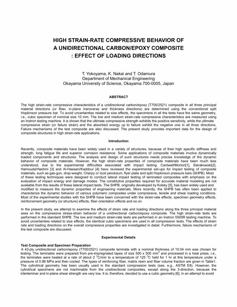
uncertainties related to size effects. The cubic specimens were cut from the composite laminate and were carefully polished toensure smooth surfaces. The longitudinal (or fiber) and in-plane transverse directions are defined as 1 and 2, and the through-thickness direction is defined as 3 (see Figure 1). Compression loading was applied in the 1-, 2- and 3- directions.
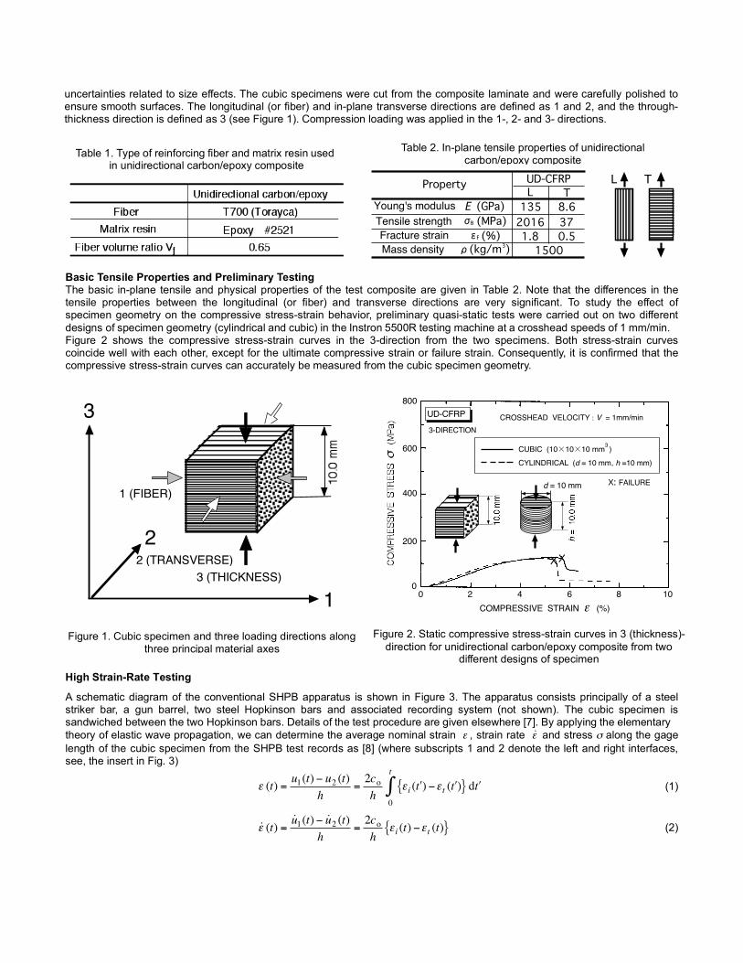
Basic Tensile Properties and Preliminary TestingThe basic in-plane tensile and physical properties of the test composite are given in Table 2. Note that the differences in thetensile properties between the longitudinal (or fiber) and transverse directions are very significant. To study the effect ofspecimen geometry on the compressive stress-strain behavior, preliminary quasi-static tests were carried out on two differentdesigns of specimen geometry (cylindrical and cubic) in the Instron 5500R testing machine at a crosshead speeds of 1 mm/min.Figure 2 shows the compressive stress-strain curves in the 3-direction from the two specimens. Both stress-strain curvescoincide well with each other, except for the ultimate compressive strain or failure strain. Consequently, it is confirmed that thecompressive stress-strain curves can accurately be measured from the cubic specimen geometry.
High Strain-Rate Testing
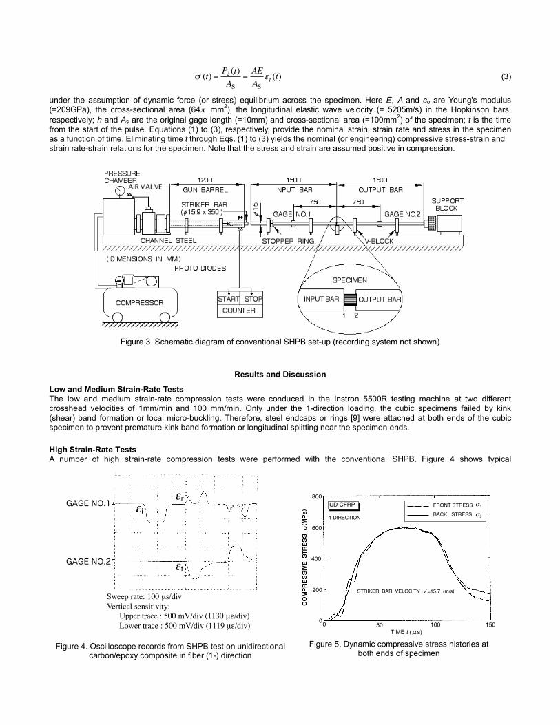
A schematic diagram of the conventional SHPB apparatus is shown in Figure 3. The apparatus consists principally of a steelstriker bar, a gun barrel, two steel Hopkinson bars and associated recording system (not shown). The cubic specimen issandwiched between the two Hopkinson bars. Details of the test procedure are given elsewhere [7]. By applying the elementarytheory of elastic wave propagation, we can determine the average nominal strain
€
ε , strain rate
€
˙ ε and stress σ along the gagelength of the cubic specimen from the SHPB test records as [8] (where subscripts 1 and 2 denote the left and right interfaces,see, the insert in Fig. 3)
€
ε (t) =u1(t) − u2 (t)
h=2coh
ε i ( ′ t ) −ε t ( ′ t ){ } d ′ t 0
t
∫ (1)
€
˙ ε (t) =˙ u 1(t) − ˙ u 2 (t)
h=
2coh
ε i (t) −ε t (t){ } (2)
Table 2. In-plane tensile properties of unidirectionalcarbon/epoxy composite
Property
E (GPa)σB (MPa)
ρ(kg/m3)
UD-CFRPL T135 8.62016 371.8 0.51500
ε (%)F
Young's modulusTensile strengthFracture strainMass density
L T
Table 1. Type of reinforcing fiber and matrix resin usedin unidirectional carbon/epoxy composite
1
2
3
3 (THICKNESS)
d = 10 mm
Figure 1. Cubic specimen and three loading directions alongthree principal material axes
1
2
3
1 (FIBER)
2 (TRANSVERSE)3 (THICKNESS)
Figure 2. Static compressive stress-strain curves in 3 (thickness)-direction for unidirectional carbon/epoxy composite from two
different designs of specimen
0 2 4 6 8 100
200
400
600
800
COMPRESSIVE STRAIN ε (%)
UD-CFRP
XX
X: FAILURE
CUBIC (10×10×10 mm )
3-DIRECTION
CYLINDRICAL (d = 10 mm, h =10 mm)
3
CROSSHEAD VELOCITY : V = 1mm/min
€
σ (t) =P2 (t)AS
=AEAS
ε t (t) (3)
under the assumption of dynamic force (or stress) equilibrium across the specimen. Here E, A and co are Young's modulus(=209GPa), the cross-sectional area (64π mm2), the longitudinal elastic wave velocity (= 5205m/s) in the Hopkinson bars,respectively; h and As are the original gage length (=10mm) and cross-sectional area (=100mm2) of the specimen; t is the timefrom the start of the pulse. Equations (1) to (3), respectively, provide the nominal strain, strain rate and stress in the specimenas a function of time. Eliminating time t through Eqs. (1) to (3) yields the nominal (or engineering) compressive stress-strain andstrain rate-strain relations for the specimen. Note that the stress and strain are assumed positive in compression.
Results and Discussion
Low and Medium Strain-Rate TestsThe low and medium strain-rate compression tests were conduced in the Instron 5500R testing machine at two differentcrosshead velocities of 1mm/min and 100 mm/min. Only under the 1-direction loading, the cubic specimens failed by kink(shear) band formation or local micro-buckling. Therefore, steel endcaps or rings [9] were attached at both ends of the cubicspecimen to prevent premature kink band formation or longitudinal splitting near the specimen ends.
High Strain-Rate TestsA number of high strain-rate compression tests were performed with the conventional SHPB. Figure 4 shows typical
Figure 4. Oscilloscope records from SHPB test on unidirectionalcarbon/epoxy composite in fiber (1-) direction
GAGE NO.1
GAGE NO.2
εiεr
εt
Sweep rate: 100 µs/divVertical sensitivity: Upper trace : 500 mV/div (1130 µε/div) Lower trace : 500 mV/div (1119 µε/div)
800
200
400
600
0 50 100 150TIME t (μs)
0
UD-CFRP
STRIKER BAR VELOCITY :V =15.7 (m/s)
1
σ 2
FRONT STRESSBACK STRESS
σ
1-DIRECTION
Figure 5. Dynamic compressive stress histories atboth ends of specimen
Figure 3. Schematic diagram of conventional SHPB set-up (recording system not shown)
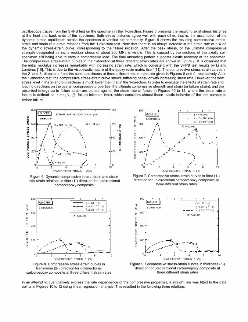
oscilloscope traces from the SHPB test on the specimen in the 1-direction. Figure 5 presents the resulting axial stress historiesat the front and back ends of the specimen. Both stress histories agree well with each other, that is, the assumption of thedynamic stress equilibrium across the specimen is verified experimentally. Figure 6 shows the resulting compressive stress-strain and strain rate-strain relations from the 1-direction test. Note that there is an abrupt increase in the strain rate at a X onthe dynamic stress-strain curve, corresponding to the failure initiation. After the peak stress, or the ultimate compressivestrength designated as σB, a residual stress of about 200 MPa is visible. This is caused by the sections of the axially splitspecimen still being able to carry a compressive load. The final unloading pattern suggests elastic recovery of the specimen.The compressive stress-strain curves in the 1-direction at three different strain rates are shown in Figure 7. It is observed thatthe initial modulus increases remarkably with increasing strain rate, which is consistent with the SHPB test results by Li andLambros [10]. This is due to the viscoelastic nature of the epoxy resin matrix itself [11]. The compressive stress-strain curves inthe 2- and 3- directions from the cubic specimens at three different strain rates are given in Figures 8 and 9, respectively. As inthe 1-direction test, the compressive stress-strain curve shows stiffening behavior with increasing strain rate. However, the flowstress level in the 2- and 3- directions is much lower than that in the 1-direction. In order to evaluate the effects of strain rate andloading directions on the overall compressive properties, the ultimate compressive strength and strain (or failure strain), and theabsorbed energy up to failure strain are plotted against the strain rate at failure in Figures 10 to 12, where the strain rate atfailure is defined as
€
˙ ε f =
€
ε B / t f (tf: failure initiation time), which considers almost linear elastic behavior of the test compositebefore failure.
In an attempt to quantitatively express the rate dependence of the compressive properties, a straight line was fitted to the datapoints in Figures 10 to 12 using linear regression analysis. This resulted in the following three relations:
Figure 7. Compressive stress-strain curves in fiber (1-)direction for unidirectional carbon/epoxy composite at
three different strain rates
0 2 4 6 8 100
200
400
600
800
COMPRESSIVE STRAIN ε (%)
ε =1.5×10 (1/s)ε = 410 (1/s)UD-CFRP
1-DIRECTION-1
ε =1.5×10 (1/s)-3
X: FAILUREX
XX
.
.
.
Figure 8. Compressive stress-strain curves intransverse (2-) direction for unidirectional
carbon/epoxy composite at three different strain rates
0 2 4 6 8 100
200
400
600
800UD-CFRP
2-DIRECTION
X: FAILURE
XX X
COMPRESSIVE STRAIN ε (%)
ε =1.5×10 (1/s)ε = 1030 (1/s)
-1
ε =1.5×10 (1/s)-3
.
.
.
0 2 4 6 8 100
200
400
600
800UD-CFRP
3-DIRECTION
X: FAILURE
X X X
COMPRESSIVE STRAIN ε (%)
ε =1.5×10 (1/s)ε = 1150 (1/s)
-1
ε =1.5×10 (1/s)-3
..
.
Figure 9. Compressive stress-strain curves in thickness (3-)direction for unidirectional carbon/epoxy composite at
three different strain rates
Figure 6. Dynamic compressive stress-strain and strainrate-strain relations in fiber (1-) direction for unidirectional
carbon/epoxy composite
ε(%)
1600
400
800
1200σB
STRIKER BAR VELOCITY :V =15.7 (m/s)
εB =1.80 (%)
€
logσ B = m log ˙ ε f + logσ 0 (4)
€
logεB = m log ˙ ε f + logε0 (5)
€
logUB = m log ˙ ε f + logU0 (6)
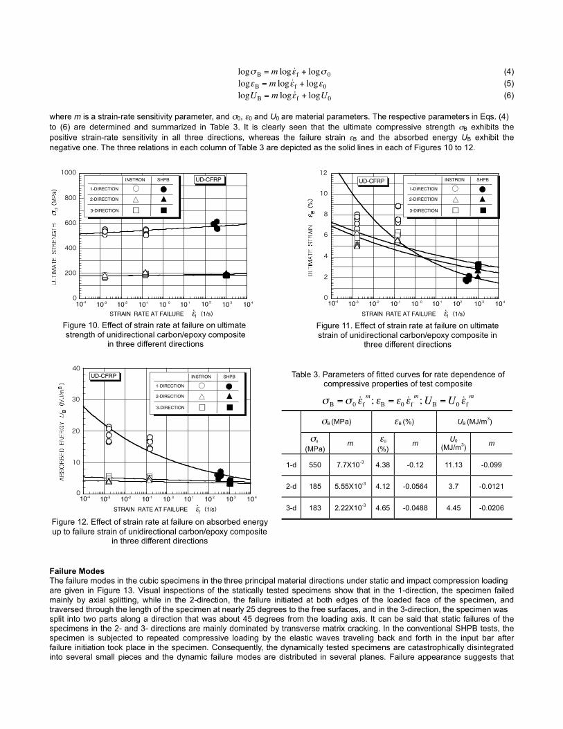
where m is a strain-rate sensitivity parameter, and σ0, ε0 and U0 are material parameters. The respective parameters in Eqs. (4)to (6) are determined and summarized in Table 3. It is clearly seen that the ultimate compressive strength σB exhibits thepositive strain-rate sensitivity in all three directions, whereas the failure strain εB and the absorbed energy UB exhibit thenegative one. The three relations in each column of Table 3 are depicted as the solid lines in each of Figures 10 to 12.
Failure ModesThe failure modes in the cubic specimens in the three principal material directions under static and impact compression loadingare given in Figure 13. Visual inspections of the statically tested specimens show that in the 1-direction, the specimen failedmainly by axial splitting, while in the 2-direction, the failure initiated at both edges of the loaded face of the specimen, andtraversed through the length of the specimen at nearly 25 degrees to the free surfaces, and in the 3-direction, the specimen wassplit into two parts along a direction that was about 45 degrees from the loading axis. It can be said that static failures of thespecimens in the 2- and 3- directions are mainly dominated by transverse matrix cracking. In the conventional SHPB tests, thespecimen is subjected to repeated compressive loading by the elastic waves traveling back and forth in the input bar afterfailure initiation took place in the specimen. Consequently, the dynamically tested specimens are catastrophically disintegratedinto several small pieces and the dynamic failure modes are distributed in several planes. Failure appearance suggests that
σB (MPa) εB (%) UB (MJ/m3)
σ0 (MPa)
m ε0
(%)m U0
(MJ/m3) m
1-d 550 7.7X10⁻³ 4.38 -0.12 11.13 -0.099
2-d 185 5.55X10⁻³ 4.12 -0.0564 3.7 -0.0121
3-d 183 2.22X10⁻³ 4.65 -0.0488 4.45 -0.0206
€
σB =σ 0 ˙ ε fm; εB = ε0 ˙ ε f
m;UB =U0 ˙ ε fm
Table 3. Parameters of fitted curves for rate dependence ofcompressive properties of test composite
Figure 10. Effect of strain rate at failure on ultimatestrength of unidirectional carbon/epoxy composite
in three different directions
0
200
400
600
800
1000
10 310 110 010-110-210-3
・STRAIN RATE AT FAILURE ε (1/s)f
10 4
SHPBINSTRON
H
1-DIRECTION
2-DIRECTION
3-DIRECTION
É
Ç
UD-CFRP
Ñ B
10-4 10 2
Figure 11. Effect of strain rate at failure on ultimatestrain of unidirectional carbon/epoxy composite in
three different directions
0
2
4
6
8
10
10 310 1 10210 010-110-210-3
・STRAIN RATE AT FAILURE ε (1/s)f
10 4
SHPBINSTRON
H
1-DIRECTION
2-DIRECTION
3-DIRECTION
É
Ç
UD-CFRP
Ñ B
10-4
12
Figure 12. Effect of strain rate at failure on absorbed energyup to failure strain of unidirectional carbon/epoxy composite
in three different directions
0
40
10
10 310 1 10 210 010-110-210-3
・STRAIN RATE AT FAILURE ε (1/s)f
10 4
SHPBINSTRON
H
1-DIRECTION
2-DIRECTION
3-DIRECTION
É
Ç
UD-CFRP
Ñ B
10-4
20
30

longitudinal splitting, interlaminar delamination and transverse matrix cracking are the dominant failure modes in thedynamically tested specimens.
Conclusions
The influences of strain rate and loading directions on the compressive stress-strain behavior of the unidirectional carbon/epoxycomposite have been studied using the cubic specimens. High strain-rate compression tests were performed with the standardSHPB over a strain-rate range of 400 to 1200/s. From the present test results, we can draw the following conclusions:
1. The ultimate compressive strength in the 1-direction is 2.5 to 3 times as high as that in other two directions at any strainrates. However, the ultimate compressive strength in all three directions is very insensitive to strain rate.
2. The ultimate compressive strain (or failure strain) in all three directions greatly decreases with increasing strain rate atfailure.
3. The absorbed energy up to failure strain in the 1-direction significantly decreases with increasing strain rate at failure. Incontrast, that in other two directions remains almost constant.
4. The failure modes in the cubic specimens significantly vary with strain rate and loading directions.
References
1. Cantwell, W.J. and Morton, J., “The Impact Resistance of Composite Materials- A Review,” Composites, 22, 347-362(1991).
2. Sierakowski, R.L., “Strain Rate Effects in Composites,” Appl. Mech. Rev., 50-1, Part 1, 741-761 (1997).3. Hamouda, A. M. S. and Hashmi, M. S. J., “Testing of Composite Materials at High Rates of Strain: Advances and
Challenges,” J. Mat. Process. Technol. 77, 327-336 (1998).4. Al-Hassani, S.T. S. and Kaddour, A.S., “Strain Rate Effects on GRP, KRP and CFRP Composite Laminates,” Key
Engineering Materials, 141-143, Part 2, 427-452 (1998).5. Kolsky, H., “An Investigation of the Mechanical Properties of Materials at Very High Rates of Loading,” Proc. Phys. Soc. B62,
676-700 (1949).6. Hosur, M.V., Alexander, J., Vaidya, U.K. and Jeelani, S., “High Strain-Rate Compression Response of Carbon/Epoxy
Laminate Composites,” Compos. Struct., 52, 405-417 (2001).7. Yokoyama, T., “Through-Thickness Compressive Characteristics of Laminated Composites at High Rates of Strain (in
Japanese),” J. Soc. Mat. Sci., 53, 272-277 (2004).8. Lindholm, U.S., “Some Experiments with the Split Hopkinson Pressure Bar”, J. Mech. Phys. Solids, 12, 317-335(1964).9. Lankford, J., “Compressive Damage and Failure at High Loading Rates in Graphite Fiber-Reinforced Polymeric Matrix
Composites, “ Advanced Composites Materials, 19, 553-563, (1991).10. Li, Z. and Lambros, J., “Determination of the Dynamic Response of Brittle Polymeric Matrix Composites by Use of the Split
Hopkinson Pressure Bar,” Compos. Sci. Technol., 59, 1097-1107 (1999).11. Tay, T.E., Ang, H.G. and Shim, V.P. W., “An Empirical Strain Rate-Dependent Constitutive Relationship for Glass-Fibre
Reinforced Epoxy and Pure Epoxy,” Compos. Struct., 33 201-210 (1995).
Figure 13. Different failure modes in cubic specimens under static and impact compression loading
STATIC IMPACTLOADING DIRECTION
3
1
3
2
3
2
1
23
1 (FIBER) DIRECTION
2 (TRANSVERSE) DIRECTION
3 (THICKNESS) DIRECTION