Embed Size (px)
Citation preview

* Corresponding author: [email protected]
High stability gel electrolytes for long life lithium ion solid state supercapacitor
Zhi Chen1,2,*, Junxiang Li1, Mengqiang Wu1, Jiaxuan Liao1,2
1School of Materials and Energy, University of Electronic Science and Technology of China, Chengdu 611731, People’s Republic of China 2Yangtze Delta Region Institute (Quzhou), University of Electronic Science and Technology of China, Quzhou, Zhejiang 324000, China
Abstract. Lithium ion capacitors with liquid electrolyte are prone to leakage, combustion, explosion and other dangerous accidents. To solve these problems, the solid gel separator prepared by polyvinylidene fluoride - six fluoropropene (PVDF-HFP) is used in this work to improve the safety and stability of lithium ion supercapacitors. The PVDF-HFP based gel separator was used to replace the commercial separator and electrolyte in the lithium ion capacitor. The solid-state lithium ion supercapacitor was matched with porous carbon (PC) and hard carbon (HC). The maximum energy density of the device is 148.76 wh/kg, even at the power density of 33.6 kW/kg, which still retains 20.6 wh/kg. In addition, 83.3% capacity of solid-state lithium-ion supercapacitor is retained after 8000 times of charge and discharge. The requirements of high power energy density, high cycle stability and high safety are realized.
1 INTRODUCTION
Traditional energy storage devices (capacitors, batteries) generally use liquid electrolyte, which may cause unknown hazards in the process of charging and discharging. The solid electrolyte with high safety has been widely concerned by many researchers. Due to its stable structure, wide electrochemical window and heat resistance, and its ability to effectively prevent the generation of lithium dendrites, solid electrolytes are more suitable for fields requiring high safety and stability [1,2]. If solid electrolyte is used in lithium-ion capacitor, three-high energy storage devices with high power energy density, high cycle stability and high safety will be obtained. However, the current research focuses on liquid state and solid-state lithium-ion batteries, the research on solid-state lithium-ion capacitors is still less [3-6]. However, due to the special structure of lithium-ion capacitors, solid-state lithium-ion capacitors can be studied by referring to solid-state lithium-ion batteries.
According to the composition of solid electrolyte membrane, it can be divided into organic polymer, inorganic solid and composite membrane [7,8]. In this work, PVDF-HFP solid polymer electrolyte membrane was studied. Among them, due to the existence of HFP, the copolymerization weakens the crystallinity of the membrane, making the interface between the electrode material and the electrolyte more stable [9,10]. In addition, in order to obtain a more porous membrane, the electrospinning process was used to prepare the membrane [11]. Finally, the PVDF-HFP solid-state separator with high porosity was prepared, which was
used as a substitute for the commercial separator and electrolyte, and assembled with PC and HC to form a solid-state lithium-ion capacitor with high power energy density, high cycling and high safety. The maximum energy density of the device is 148.76 wh/kg, even at the power density of 33.6 kW/kg, which still retains 20.6 wh/kg. In addition, 83.3% capacity of solid-state lithium-ion supercapacitor is retained after 8000 times of charge and discharge. This provides some new ideas for the development of the next generation of lithium ion supercapacitors.
2 Experimental methods
2.1 Preparation of PVDF-HFP electrolytes
Adding 1.239 g PVDF-HFP particles to 10 ml DMF solution and stirring for 12 hours, a uniform half gel solution was obtained. After that, the solution was electrospun into a white flake polymer and dried in a vacuum oven at 75 ℃ for 24 hours. Finally, the tablet press is used to cut it into the required diaphragm. Before assembling the button cell, it is necessary to immerse the diaphragm in the electrolyte for half an hour, and obtain the gel solid electrolyte. The preparation process is shown in Figure 1.
2.2 Characterization of materials
FE-SEM (jsm-5900lv, jeol) was used to characterize the microstructure of the membrane. The porosity is calculated by formula of porosity = (wt-w0)/ρV (wt and
© The Authors, published by EDP Sciences. This is an open access article distributed under the terms of the Creative Commons Attribution License 4.0
(http://creativecommons.org/licenses/by/4.0/).
E3S Web of Conferences 257, 01084 (2021) https://doi.org/10.1051/e3sconf/202125701084AESEE 2021

w0 are the mass (g) before and after the test, V is the volume (cm3), ρ is the density of n-butanol (g/cm3)). The liquid absorption rate is calculated by formula of liquid absorption rate = (wt-w0)/ w0. Put the diaphragm directly above the alcohol lamp for combustion test to verify its thermal stability.
2.3 Test of electrochemical performance
The gel membrane (after immersion in electrolyte) and two stainless steel sheets were assembled into a battery for EIS test, and ionic conductivity was calculated according to formula of σ=L/RS (Where R is the impedance value after fitting, S is the area of the gel membrane (cm2), and L is the thickness of the gel membrane (cm)). In addition, the button cell was assembled with stainless steel sheet and lithium sheet for electrochemical stability window test. 80 wt% active materials, 10 wt% PVDF and 10 wt% super P with proper amount of NMP were agitated and coated on the collector (anode copper foil, cathode aluminum foil), and then dried to obtain the electrode plate. In the glove box, electrode plates, lithium sheets, gel separators after absorbing the electrolyte (1 M LiPF6 in EC: DEC:DMC (1:1:1)) are assembled.
Figure 1 Preparation process of gel electrolytes.
3 Results and discussion
3.1 Characterization of materials
The SEM image of the gel electrolyte is shown in Figure 2a. After the treatment of electrospinning process, the microstructure shows a complex network structure of irregular filaments. The special structure leads to more pores and large specific surface area, which will promote the absorption of electrolyte and provide more Li+ and PF6- ions channels, thus improving the electrochemical performance of the device. The absorbency and porosity are two key parameters for the gel membrane. High absorbency is conducive to promoting the migration rate of ions. High porosity can enhance the storage and absorption of electrolyte.
The photos and test results of the gel membrane before and after the absorption of electrolyte and glycol are shown in Figure 2b-e. It is seen that the liquid membrane shows the quasi solid morphology of the gel state after absorbing the liquid. The absorbency and porosity of gel electrolyte were 379.3% and 26.53% based on formula. Their good properties were caused by the porous structure resulting from electrospinning. Figure 2h shows the combustion test of the gel membrane. It can be seen that the PVDF-HFP gel
membrane obtained by electrospinning has very good heat resistance. During the test, the membrane does not burn, but it shrinks at the edge. Therefore, if there are accidents such as collision, overcharge and other easy to induce combustion, the gel diaphragm can provide higher security.
Figure 2. (a) SEM image of gel electrolyte. Before (b) and
after (c) the absorption of electrolyte. Before (b) and after (c) the absorption of glycol. Porosity (f), liquid absorption rate (g)
and combustion test of gel electrolyte.
3.2 Electrochemical performance test
Figure 3a is the EIS of the gel electrolyte. For the conventional test, the curve is composed of semicircle at high frequency and oblique line at low frequency. The semicircle is caused by the impedance caused by the movement of lithium ion and the reaction of electrode material. The two electrodes in the conductivity test of the gel membrane are stainless steel sheets, which do not react with the electrolyte, so that the diameter of the semicircle is infinitely enlarged, and the final curve is approximately a straight line. The conductivity of the gel membrane is 2.849 mS/cm by fitting the curve.
Electrochemical stability window is one of the key indexes to judge the electrochemical stability of membrane. In Figure 3b, the linear sweep voltammetric curve of the gel electrolyte and lithium sheet and stainless steel sheet are assembled. Between 2.5 V and 4.5 V, the current of the battery maintains a relatively stable state. When it approaches 4.5 V, its value rises rapidly, indicating that additional redox reaction occurs, which will destroy the structure of the membrane [106]. It should be noted that the test range of capacitive cathode is 2-4.5 V, which may affect its electrochemical performance test, but battery anode (0-3 V) and lithium ion capacitor (1.5-4 V) are not affected by it.
2
E3S Web of Conferences 257, 01084 (2021) https://doi.org/10.1051/e3sconf/202125701084AESEE 2021

Figure 3. EIS (a) and LSV (b) of gel electrolyte. CV curve (c),
charge-discharge curves (d), rate performance (e) and long cycle performance (f).
By setting the voltage range to 2.0-4.5 V, the
electrochemical performance of half cell was evaluated by using gel membrane as electrolyte. Figure 3c shows the CV curve at the scanning rate of 5-200 mV/s. Even at 200 mV/s, the curve is still quasi rectangular, indicating that cell has good reversibility. The charge-discharge curves at 0.1-10 A/g are shown in Figure 4b, and the curves are basically quasi triangular, which can well show the ideal capacitance behavior. Figure 3d shows the rate performance of PC at different current densities. In the electrochemical stability window test, it is found that the gel electrolyte may have additional reaction at about 4.5 V, which may adversely affect the capacitive cathode test. The specific capacity of PC is 88.8 mAh/g at 0.1 A/g. When the current density up to 0.2, 0.5, 1, 2, 5 and 10 A/g, the specific capacity of PC is 86.8, 84.5, 82.0, 77.6, 66.7 and 58.2 mAh/g, respectively (Figure 3e). The specific capacity was maintained at 34.1 mAh/g after 8000 cycles of long cycle test at 5A/g (Figure 3f). Although the electrochemical range of the gel diaphragm limits its electrochemical performance, it still performs better than other carbon materials, thanks to the excellent pore volume and super specific surface area as well as the pseudo capacitance effect caused by rich oxygen elements of PC.
By setting the voltage range to 0.01-3.0 V, the electrochemical performance of HC was evaluated in the half cell with gel separator as electrolyte, as shown in Figure 4a. The CV curves and charge discharge curves are similar to those in liquid electrolyte. When the current density is 0.1, 0.2, 0.5, 1, 2, 5 A/g, the specific capacity of the electrolyte is 250.3, 216.4, 190.9, 171.8, 152.8, 119.5 mAh/g, respectively. It is noteworthy that, thanks to the special structural stability of the gel electrolyte, which exhibited better results in the long cycle test at 1 A/g. This results implies that the solid
lithium ion capacitor based on the gel electrolyte diaphragm will have better cycling stability.
A solid lithium ion capacitor was constructed by using PC as a capacitive cathode and using pre-lithium HC as battery anode and using PVDF-HFP gel membrane as electrolyte. Figure 5a shows the charge storage mechanism of solid state lithium-ion capacitors. In the charging process of PC//HC, PF6- is absorbed by the porous structure and defects of PC cathode, while Li+ is inserted into the interlayer space of HC, and the reverse process occurs in discharge. In addition, choosing the working voltage range of 1.5-4 V can avoid the side reaction of gel septum during charging and discharging.
Figure 4. Electrochemical performance of HC based on gel electrolyte. CV curve(a), charge-discharge curve (b), rate performance (c) and long cycle performance (d) of HC.
The electrochemical performance test of PC//HC
solid state lithium ion capacitor is shown in figure 5b-e. Because cathode and anode have two different energy storage mechanisms, the shape of CV Curve is slightly different from the ideal situation. With the increase of scanning speed, the basic style of the curve is well preserved, there is no serious deformation, and it still shows an approximate symmetrical shape. The charge-discharge curves are triangular, which proves that it has excellent electrochemical reversibility. The power and energy density are calculated according to the charge-discharge curve. Its maximum energy density can reach 148.76 Wh/kg (100.36 W/kg), and it still retains 20.6 Wh/kg at 33.6 kW/kg. The stability of the solid lithium ion capacitor has been greatly improved due to the better performance of the HC cell anode using the gel diaphragm. Under the high current density of 5 A/g, after 8000 charge discharge cycles, the energy density is stabilized to 83.3% of the initial capacity, and the decay rate of each cycle is only 0.00209%. During the cycle, the internal resistance and lithium consumption may lead to the decrease of capacity. In short, a reasonable combination of anode and cathode and pre-lithium technology and the use of highly stable solid-state gel separator, PC//HC solid state lithium ion capacitors show high energy power density, excellent cycle stability and good safety performance, the basic construction idea of "three-high" electrochemical energy storage equipment is realized.
3
E3S Web of Conferences 257, 01084 (2021) https://doi.org/10.1051/e3sconf/202125701084AESEE 2021
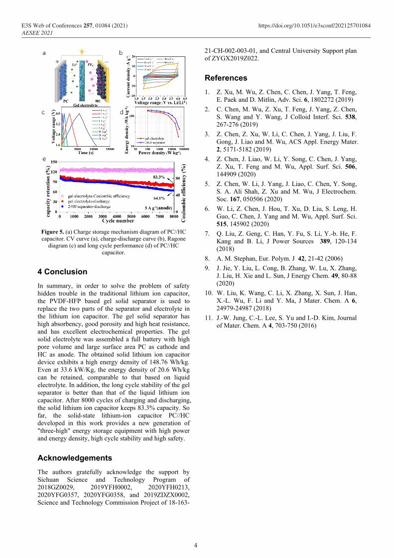
Figure 5. (a) Charge storage mechanism diagram of PC//HC capacitor. CV curve (a), charge-discharge curve (b), Ragone
diagram (c) and long cycle performance (d) of PC//HC capacitor.
4 Conclusion
In summary, in order to solve the problem of safety hidden trouble in the traditional lithium ion capacitor, the PVDF-HFP based gel solid separator is used to replace the two parts of the separator and electrolyte in the lithium ion capacitor. The gel solid separator has high absorbency, good porosity and high heat resistance, and has excellent electrochemical properties. The gel solid electrolyte was assembled a full battery with high pore volume and large surface area PC as cathode and HC as anode. The obtained solid lithium ion capacitor device exhibits a high energy density of 148.76 Wh/kg. Even at 33.6 kW/Kg, the energy density of 20.6 Wh/kg can be retained, comparable to that based on liquid electrolyte. In addition, the long cycle stability of the gel separator is better than that of the liquid lithium ion capacitor. After 8000 cycles of charging and discharging, the solid lithium ion capacitor keeps 83.3% capacity. So far, the solid-state lithium-ion capacitor PC//HC developed in this work provides a new generation of "three-high" energy storage equipment with high power and energy density, high cycle stability and high safety.
Acknowledgements
The authors gratefully acknowledge the support by Sichuan Science and Technology Program of 2018GZ0029, 2019YFH0002, 2020YFH0213, 2020YFG0357, 2020YFG0358, and 2019ZDZX0002, Science and Technology Commission Project of 18-163-
21-CH-002-003-01, and Central University Support plan of ZYGX2019Z022.
References
1. Z. Xu, M. Wu, Z. Chen, C. Chen, J. Yang, T. Feng, E. Paek and D. Mitlin, Adv. Sci. 6, 1802272 (2019)
2. C. Chen, M. Wu, Z. Xu, T. Feng, J. Yang, Z. Chen, S. Wang and Y. Wang, J Colloid Interf. Sci. 538, 267-276 (2019)
3. Z. Chen, Z. Xu, W. Li, C. Chen, J. Yang, J. Liu, F. Gong, J. Liao and M. Wu, ACS Appl. Energy Mater. 2, 5171-5182 (2019)
4. Z. Chen, J. Liao, W. Li, Y. Song, C. Chen, J. Yang, Z. Xu, T. Feng and M. Wu, Appl. Surf. Sci. 506, 144909 (2020)
5. Z. Chen, W. Li, J. Yang, J. Liao, C. Chen, Y. Song, S. A. Ali Shah, Z. Xu and M. Wu, J Electrochem. Soc. 167, 050506 (2020)
6. W. Li, Z. Chen, J. Hou, T. Xu, D. Liu, S. Leng, H. Guo, C. Chen, J. Yang and M. Wu, Appl. Surf. Sci. 515, 145902 (2020)
7. Q. Liu, Z. Geng, C. Han, Y. Fu, S. Li, Y.-b. He, F. Kang and B. Li, J Power Sources 389, 120-134 (2018)
8. A. M. Stephan, Eur. Polym. J 42, 21-42 (2006)
9. J. Jie, Y. Liu, L. Cong, B. Zhang, W. Lu, X. Zhang, J. Liu, H. Xie and L. Sun, J Energy Chem. 49, 80-88 (2020)
10. W. Liu, K. Wang, C. Li, X. Zhang, X. Sun, J. Han, X.-L. Wu, F. Li and Y. Ma, J Mater. Chem. A 6, 24979-24987 (2018)
11. J.-W. Jung, C.-L. Lee, S. Yu and I.-D. Kim, Journal of Mater. Chem. A 4, 703-750 (2016)
4
E3S Web of Conferences 257, 01084 (2021) https://doi.org/10.1051/e3sconf/202125701084AESEE 2021