Embed Size (px)
Citation preview

CC-687A 7
High speed response and miniature size
Small flow sensor FSM series

Miniature size and high-responseThree series of compact flow sensors to match different applicationsUnprecedentedly compact size and high-speed response are realized using a platinum sensor chip incorporating silicon micromachining and a newly proposed rectifying mechanism.The thermal flow sensor is used for applications such as confirmation of electronic part suction, leakage inspection, and gas flow control.
Indicator/FSM-H-D 30X32
Flow display section (3-digit digital display)
Flow display section (3-digit digital display)Flow display section (3-digit digital display)
Switch output (alarm lamp)
Switch output (alarm lamp)Switch output (alarm lamp)
Two-directional mounting (side, base)
Two-directional mounting (side, base)
Indicator/FSM-A-D 30X32
Compact, high-speed, extremely small flow rate
Compact, high-speed response
Flow range
Flow range
Detects extremely small flow rates of 1 mR/min or less at high speed.Perfect for leakage and pinhole inspections.
Select either an integrated or separated indicator to increase the range of applications.
Compatible with argon (Ar) and carbon dioxide (CO2). (Option)

Miniaturized, light-weight High-speed response Free installation position
Usable with vacuums
Control flow rates
Ample variations
A miniaturized in-line filter for small flow sensor is available.
No straight piping section needed
Flow display section (3-digit digital display)
Switch output (alarm lamp)
Indicator/FSM-V-D 30X32
Elbow can be used.
Miniaturized, ultra-high-speed response
Flow range
Size
Compact, light-weight
High-speed response
Separated Integrated Material Switch output
Analog output
Compact, light-weight
Separated indicator Technical data
High-speed response
Separated Integrated Material
SeparatedMiniaturized, light-weight
Instantaneous response
Material
Switch output
Analog output
Switch output
Analog output
Interactive direction
Low flow
Extremely small flow
Large flow
Indicator
Maintain sensor performance and prevent problems.
See the next page for examples of applications and series variations.
Material Output PageFlow rangeInteractive detection
Response speedSeries
Dramatic downsizing and a 5 ms high-speed response have realized a novel design.
This sensor can be installed in small spaces or on moving sections, facilitating downsizing and weight reduction.
High-speed response is realized by incorporating a platinum sensor chip processed with silicon micromachining. Use this sensor with devices having a short cycle time, such as to check the suction of the machine on which it is mounted.
The sensor can be mounted in any direction top, bottom, left, or right.
The newly proposed rectifying structure eliminates the need for a straight piping section upstream or downstream.
Output includes analog output and digital display and switch output to detect errors visually and with switches.Select the type suited to the application.
Use this sensor even for vacuum applications, such as confirming the suction of the machine on which it is mounted. The argon and carbon dioxide types are for positive pressure.
Comparison of volume with conventional parts
Positive/negative pressure combination
Comparison of response speed with conventional part
Company A
Company B
or less or less

Active in different applicationsThis small flow sensor is used in fields such as machinery, automobiles, measuring instruments, and precision equipment; advanced fields such as semiconductors and biotechnology; and medicine and foodstuffs.
Lif
eIn
du
stry
Applicable fluid
Sensor applicationsLeakage inspectionPinhole inspectionIonizer purge gas confirmationWelding gas controlPurge gas flow controlContact detectionSuction detection
Foodstuff/medicine
Liquid crystals
Leakage inspection
Ionizer purge gas confirmation
Welding argon and carbon dioxide flow control
The inspection cycle time can be shortened.Measurements can be made immediately after filling containers.Even when pressure is extremely low, output is made in proportion to the pinhole, so acceptability is judged and status confirmed.
Compatible with different flow ranges.Easily execute flow control with the in-line flow controller (customized order).
Compatible with different flow ranges.Easily execute flow control with the in-line flow controller (customized order).
N2 gas control for laser oscillators and semiconductor manufacturing equipment.
Control of purge gas is indispensable for maintaining device performance.This miniature sensor is easily incorporated into devices.
Even judgments not completed with a pressure sensor because of the small differential pressure are accurately made based on flow rate.
High-speed response comparable to pressure sensor. The response differs with pipe inner volume and pressure, etc.Flow detection eliminates the need for adjustment based on pressure fluctuation and erroneous detection.Clogging of the nozzle and filter are detected.Suction errors such as inclined suction are controlled with flow detection.
Automobiles, etc.
Semiconductors Purge gas flow controlSemiconductors
Machine manufacturing Contact confirmation
Electronic parts Suction confirmation
(For nozzle diameter: ø0.3, vacuum pressure: -70 kPa)Comparison with pressure sensor Small flow sensor (using FSM-N-010) Pressure sensor
Flow difference Pressure difference
Suction Suction
Very clear!
1
2
3
4
Examples of small flow sensor application
Extremely small flow
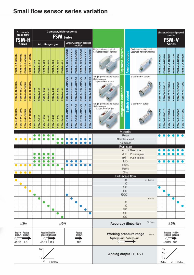
Compact, high-response Miniaturized, ultra-high-speed response
Air, nitrogen gas Argon, carbon dioxide (option)
Single-point analog outputSeparated indicator (optional)
Single-point analog outputSeparated indicator (optional)
2-point NPN output
Sepa
rate
d in
dica
tor
Inte
gra
ted
ind
icat
or
Sw
itch
ou
tpu
tA
nal
og
ou
tpu
t
Single-point analog outputSwitch output 2-point NPN output
Single-point analog outputSwitch output 2-point PNP output
2-point PIP output
Material
Port size
Full-scale flow
Accuracy (linearity)
Working pressure range
Analog output
FS flow
Negative pressure
Positive pressure
Negative pressure
Positive pressure
Negative pressure
Positive pressure
Negative pressure Positive pressure
Positive pressure
ResinStainless steel
fiber tubePush-in jointPush-in joint
Aluminum
øøø
Small flow sensor series variation

INTRO 3
Note that some items described as [CAUTION] may lead to serious results depending on the situation.In any case, the important description that must be observed is listed.
When a dangerous situation may occur if handling is mistaken, leading to minor injuries or physical damages.
When a dangerous situation may occur if handling is mistaken, leading to fatal or serious injuries.
When a dangerous situation may occur, or when there is high urgency to a warning leading to fatal or serious injuries, if handling is mistaken.
ISO4414 and JIS B 8370 (pneumatic system rules), JIS B 8368 (pneumatic cylinder)JPAS 005 (principles for use and selections of pneumatic cylinder)High Pressure Gas Maintenance Law, Occupational Safety and Sanitation Laws, other safety regulations and corporate standards, etc.
Inspect and service the machines and devices after confirming safety of the entire system related this product.Care must be taken even after operation is stopped since there may be hot or charged section.When inspecting or servicing the device, turn off the energy source (pneumatic or hydraulic source), and turn off power to the facility. Discharge the residual pressure and pay special attention to possible leakages of water and electricity.When starting and restarting a machine or device using pneumatic components, make sure the system safety, such as popping-out prevention measures, etc. are secured.
Contact CKD when using the product outside the unique specifications range, when using it outdoors, and when using it under the conditions and environment below. Do not attempt to modify or additionally machine the product.
Use for special applications requiring safety including nuclear energy, railroad, aviation, ship, vehicle, medical equipment, equipment or components directly contacting to beverage, food, etc., amusement equipment, emergency shutoff circuits, press machines, brake circuits, safeguard etc.Use for applications where life or assets could be adversely affected, and special safety measure are required.
Do not handle the products, pipe, nor remove components before confirming safety.
Warning and cautions on the pages below must be observed to prevent accidents.
For the safety on equipment design/control, etc., corporate standards and regulations, etc., must be observed.
Use the products in accordance of specifications.
These products on this catalog are designed and manufactured as parts for general industrial machines.Therefore, the person that has sufficient knowledge and experience must handle them.
When designing and/or manufacturing equipment using CKD products, the manufacturer is obligated to check that the device safety mechanism, pneumatic or hydraulic control circuits and electric controls that control these pieces of equipment be secured.It is important to select, use, handle or maintain the product appropriately to ensure that CKD products be used safely.Observe warning and cautions to ensure the safety of equipment.Check that the safety of equipment be ensured, then manufacture safe equipment.
Warning
Caution:
Warning:
Danger:
Safety cautions are ranked by the safety cautions as [danger] [warning] [caution] in this section.
5
4
3
2
1
Always read this section before starting use.
Safety precautions
1
1
2
3
4
2

INTRO 4
Pneumatic components: warning/cautionsto secure safetyAlways read this section before starting use.
Danger Design & selection
Working fluid A flammable fluid must not be used.
Working environmentFlammable environmentDo not use the product in flammable gas environment.Since explosion-protection is not taken, explosion or firemay be caused.
Small flow sensor FSM-H/FSM/FSM-V series
Warning Design & selection
Working fluidThe product can not be used as a business mater.Not conformed to the Measurement Law, do not use theproduct for the commercial purpose. Use the product asan industrial sensor.Do not use the product with other than applicable workingfluids, or the accuracy can not be guaranteed.Install a filter, an air dryer and an oil mist filter (microalescer) onto the primary side (upstream) of the sensorsince the compressed air from the compressor containsdrain (water, oil oxide and foreign material, etc.) Mesh(wire net) in a sensor is used to rectify the flow in thepipe. Always install a filter since this mesh is not a filter toremove foreign materials, etc.
Working environmentCorrosive environmentDo not use the product in an environment containingcorrosive gas such as salphur dioxide, etc.Ambient temperature/fluid temperatureUse the product within the ambient and fluid temperatureranges 0 to 50 ˚C. Even in the specified temperaturerange, do not use the product where ambient and fluidtemperatures will change suddenly, and form dewcondensations.Maximum working pressure/usage flow rangeUse the product in accordance with specifications. If usedout of the maximum working pressure and working flowrange, the product may result in failures.Drip proof environmentThe protective structure of this product is equivalent toIP40. Do not install the product where moisture, salt, dustor swarf is contained, or where pressurized, or depres-surized, neither. The product can not be used where thetemperature changes suddenly or has high humiditysince a failure by dew condensation may be produced inthe body.
Pre-filter Air dryer Oil mist filter(Micro alescer)
Small flow sensorFSM series
Caution Design & selection
Flow rate unitThe flow rate of this product is measured by mass flownot depended with temperature and pressure. Unit is R/min where mass flow is converted to volumetric flow at 20˚C and 1 atmospheric pressure (101kPa).
Regulator
<Recommended circuit>
Air source
When a valve is used in the primary side of the sensor,an oil-prohibited valve must be used. The sensor maymalfunction or be destroyed by splash of grease and oil,etc.
Withstanding pressureWithstanding pressure may vary per series. Care must betaken to select the product.
OverflowEven if twice as much overflow as each series measuringrange is applied to the sensor, it is no problem, however,if dynamic pressure is applied near to the maximumworking pressure, (when the pressure applied to theprimary side with the secondary side released.), thesensor may fail. When feeding workpieces during leak-age inspection, if dynamic pressure is applied, alwaysprovide a by-pass circuit or a needle valve to avoiddynamic pressure applying to the sensor.
Adsorption verification, etc.When using this product with adsorption verification, etc.,select the flow rate range according to vacuum range andadsorption nozzle diameter. Refer to Page 42 on theattached sheet for [flow rate theory calculation method].
When using this product with adsorption verification, etc.,always install an air filter (filtration rating 30 µm or less)onto the upstream of suction side to prevent suction offoreign materials. (Use of miniature inline filter for FSM,FSM-V is recommended. Refer to Page 46 for details).In FSM-V series, if fiber tube model is used within flowrate range of ±5R/min or ±10R/min, pressure lossincreases per working pressure, the required flow maynot be reached. Care must be taken.When using this product with adsorption verification, etc.,considering atmospheric dew point and ambient tempera-ture of this product, use the product under the conditionsthat dew condensations will not be formed in the inside ofpipe.When using this product with adsorption verification, etc.,response time may delay per pipe volume between thisproduct from adsorption nozzle. In that case, takecountermeasures such as, reducing piping volume, etc.When using the product with vacuum applications suchas air absorption, etc., do not bend the tube near thepush-in joint section. If stress is applied to the tube nearthe push in joint, insert the tube into the push-in joint afterinserting the insert ring.

INTRO 5
Pneumatic components: warning/cautionsto secure safetyAlways read this section before starting use.
Small flow sensor FSM-H/FSM/FSM-V series
OFF
ON
Setpoint or less ON
Ads
orpt
ion
verif
icat
ion
OFF
ON
Setpoint and over ON
Flow sensor (switch)Pressure sensor (switch)
Atmospheric pressure side
High vacuum side
Flow rate 0 side
Flow rate large side
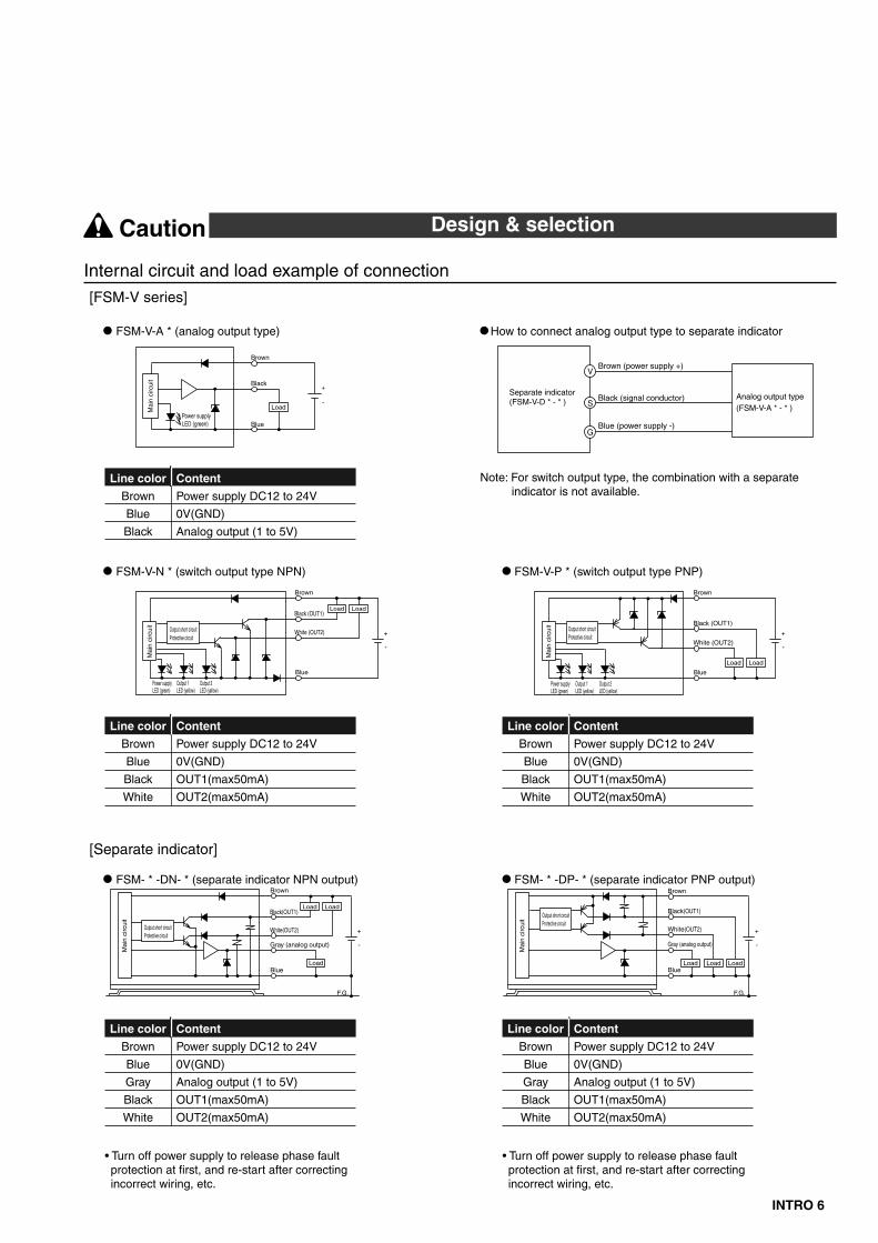
Content
Power supply DC12 to 24V
0V(GND)
Analog output (1 to 5V)
OUT1(max50mA)
OUT2(max50mA)
Line color
Brown
Blue
Gray
Black
White
Content
Power supply DC12 to 24V
0V(GND)
Analog output (1 to 5V)
Line color
Brown
Blue
Black
Content
Power supply DC12 to 24V
0V(GND)
Analog output (1 to 5V)
OUT1(max50mA)
OUT2(max50mA)
Line color
Brown
Blue
Gray
Black
White
[FSM-H/FSM series]
Example of internal circuit and load connection
How to connect analog output type to separate indicator
FSM-H-P/FSM-P (indicator type PNP output)
(Note) In metal body (stainless steel body and aluminum body) types, connect F.G. of equipment connected to - or + power supply to the body.Do not attempt insulation resistance and pressure tests while F.G. is connected, or may result in damage or burn.
FSM-H-A/FSM-A (analog output type)
FSM-H-N/FSM-N (indicator type NPN output)
Outpu
t short-
circuit
protec
tion
Outpu
t short-
circuit
protec
tion
max50mA
max50mA
max50mA
Black line (analog output)
Brown wire (power supply +)
Blue line (power supply -)
-+
White line (switch output)
Black line (switch output)
Brown wire (power supply+)
Gray line (analog output)
Blue line (power supply-)
-+
-+
Load
Load
LoadLoad
Load
LoadLoad
max50mA
Blue line (power supply-)
White line (switch output)
Black line (switch output)
Brown line (power supply+)
Gray line (analog output)
Mai
n ci
rcui
tM
ain
circ
uit
Mai
n ci
rcui
t
Separate indicator(FSM-A-D * - * /FSM-H-D * - * )
G
S
V
Analog output type(FSM-A- * - * /FSM-H-A- * - * )
Blue (power supply-)
Brown (power supply+)
Black (signal conductor)
Caution Design & selection
Adsorption verification, etc.When the sensor for adsorption verification is replacedfrom the pressure sensor (switch) to the flow sensor(switch), in the image (refer to right Fig.), the theory ofsensor output (switch output) is reversed. Care must betaken since change and modification of sequenceprogram of PLC are required. If source pressure/vacuumis not supplied especially when equipment power turnedon, problems must not be created in sequence program,etc., of PLC since flow sensor (switch) maintains [flowrate 0]=[sensor output (switch output) ON].
INTRO 6
Separate indicator(FSM-V-D * - * )
G
S
V
Analog output type(FSM-V-A * - * )
Blue (power supply -)
Brown (power supply +)
Black (signal conductor)
Content
Power supply DC12 to 24V
0V(GND)
Analog output (1 to 5V)
OUT1(max50mA)
OUT2(max50mA)
Line color
Brown
Blue
Gray
Black
White
Content
Power supply DC12 to 24V
0V(GND)
Analog output (1 to 5V)
OUT1(max50mA)
OUT2(max50mA)
Line color
Brown
Blue
Gray
Black
White
Content
Power supply DC12 to 24V
0V(GND)
OUT1(max50mA)
OUT2(max50mA)
Line color
Brown
Blue
Black
White
Content
Power supply DC12 to 24V
0V(GND)
OUT1(max50mA)
OUT2(max50mA)
Line color
Brown
Blue
Black
White
Content
Power supply DC12 to 24V
0V(GND)
Analog output (1 to 5V)
Line color
Brown
Blue
Black
[Separate indicator]
[FSM-V series]
Internal circuit and load example of connection
FSM- * -DP- * (separate indicator PNP output)FSM- * -DN- * (separate indicator NPN output)
• Turn off power supply to release phase fault protection at first, and re-start after correcting incorrect wiring, etc.
• Turn off power supply to release phase fault protection at first, and re-start after correcting incorrect wiring, etc.
LoadLoadLoad
Gray (analog output)
White(OUT2)
Mai
n ci
rcui
t
Black(OUT1)
Blue
F.G.
Protective circuitOutput short circuit
Brown
-
+
Load Load
Load
F.G.
Gray (analog output)
White(OUT2)Protective circuitOutput short circuit
Mai
n ci
rcui
t
Brown
Black(OUT1)
Blue
-
+
How to connect analog output type to separate indicator
Note: For switch output type, the combination with a separate indicator is not available.
Mai
n ci
rcui
t
Output 2LED (yellow)
Output 1LED (yellow)
White (OUT2)
Brown
Black (OUT1)
Blue
Power supplyLED (green)
Load
Protective circuitOutput short circuit
Load
-
+
Mai
n ci
rcui
t
Output 2LED (yellow)
Output 1LED (yellow)
Load
White (OUT2)Protective circuitOutput short circuit
Brown
Black (OUT1)
Blue
Power supplyLED (green)
Load
-
+
FSM-V-P * (switch output type PNP)
Mai
n ci
rcui
t
Brown
Black
BluePower supplyLED (green)
Load-
+
FSM-V-N * (switch output type NPN)
FSM-V-A * (analog output type)
Caution Design & selection

INTRO 7
Pneumatic components: warning/cautionsto secure safetyAlways read this section before starting use.
WiringLine color must be checked when wiring. Check thewiring color with handling precaution, since improper wireconnection may result in damage, failure or malfunctionof the sensor.Insulation of wiring must be checked.Eliminate contact, ground fault and terminal insulationdefective with other circuits, or overcurrent will beadmitted into the sensor to damage.For the power supply to be used, use DC safety powersupply insulated form alternating current power supplyand in rated range. If power supply is not insulated,electric shock may be created. If power supply is notstabilized, the peak magnitude in summer may exceedthe rated value, causing damage of this product, orreducing the accuracy.For wiring, stop control unit/machinery and equipment,and turn off the power supply.Sudden operation maycreate not anticipated motions, causing a danger. First,attempt energizing test, then set the desired switch datawhile control unit, machinery and equipment are stopped.Discharge static electricity built in body, tool and equip-ment before and during work. Use a wire with elasticity aswire for robot connection in the movable part.Do not use the product out of power supply voltagerange. If voltage more than usage range is applied, or ifalternating current power (AC100V) applied, causingdamage or burn.
This product and wiring must be installed as far away aspossible from noise source such as strong electric line,etc. Take other countermeasures for a surge on thepower supply line.Do not short-circuit a load, or causing damage or burn.Use DC safety power supply thoroughly insulated fromthe AC primary side for a power supply for the metal body(stainless steel and aluminum bodies) type, while con-necting either + or - side on the power supply to F.G.Variable resistor (clamping voltage approximate 40V) isconnected between the inside power circuit of metal bodytype and the metal body to prevent breakdown of thesensor. High potential and insulation resistance testsbetween the inside power circuit of metal body type andthe metal body must not be done. If required, attemptthese tests after wiring is disconnected. The excessiveelectric potential difference between power supply andmetals body makes inside parts burn. When electricwelding equipment or frame and when creating a short-circuit accident after metal body type installed, connectedor wired, transient high and surge voltages may run inground line or fluid path connected to the componentsabove when welding current runs or when welding,causing a damage. Remove all F.G. connections of theproduct and electric wiring before work such as electricwelding, etc.
Small flow sensor FSM-H/FSM/FSM-V series
Danger Installation & adjustment
WiringPower supply voltage and outputs must be used with thespecified voltage. Applying the voltage more than speci-fied voltage may cause malfunction, damage of sensor,electric shock or fire.
Warning Installation & adjustment
Do not apply load more than the rated output. Damageor fire of the output may be caused.

INTRO 8
PipingFSM-H/FSM must be piped, while matching the flowdirection and direction specified on the body.For FSM-V, the direction of arrow on the body must bechecked, considering the flows direction and switchingoperation, then install and pipe the product.
When piping a sensor, refer to the torques below not toapply excessive screw-in and load torques to the port.
Flash the pipe to remove foreign substances and swarf,etc., in inside of pipe before piping. If many foreignmaterials and swarf, etc. entrain into the inside, therectifier and the sensor tip could be damaged.When piping, apply a spanner on the metal section not toapply forces onto the resin section.
When piping, care must be taken that sealing tape andadhesive must not enter into the inside.
0.5 to 1.03 to 56 to 8
M5Rc1/8(G1/8)Rc1/4
Set screw Tightening torque N•m[Reference value]
When wrapping fluoro resin sealing tape on thescrew section, wrap the tape once or twice whileleaving 2 to 3 threads from the end, then holddown the tape with your nail top to contact thetape on the thread closely. When using liquidsealant, leave 1 to 2 threads from the screw endto apply the sealant, while watching too muchsealant must not be applied. Do not apply sealanton the thread section of component.
Solid
or l
iqui
d se
alan
t age
nt
Solid
or l
iqui
d se
alan
t age
nt
(Not good)(Good)(Not good)
Solid/fluid sealant agentSealing tape
(Good)
When using the metal body with OUT side released,always connect a joint, or the port filter may be removed.If a push-in joint is used, the tube must be insertedcertainly. Pulls the tube to check that the tube not become out. Cut the tube at the right angle with the dedicat-ing knife.Connect fiber tube as the following steps ( 1 to 5 ).
Collar
3 Connect while checking if fiber tube is properly inserted through the collar.
2 Cut the end of fiber tube at the right angle.
5 Pull the collar in the front to lock.
4 Insert air fiber until the end will reach wall.
1 Collar is set in the most deep position.
AdjustmentIf a switch is activated in unstable flow rate state such asa fluid pulsation, etc., unstable operation may be pro-vided. In this case, maintain a sufficient differencebetween two setpoints, or avoid switch setting in theunstable area, then use the product after checking thatswitching operation be stabilized.When setting FSM-V series; switch output type setting,use a minus headed screw driver matching trimmer slit(0.5W X 1.9L X 0.45D) or a cross-point screwdriver for 0bit. Also, revolution range of trimmer is 240 degrees.Further rotation or rotation while strongly held may resultin damage.
Flow direction
Flow direction
Switc
h va
lve
Vacu
um fi
lter
Adso
rptio
n noz
zle
Blow Adsorption side: 3 to 5VBlow side: 3 to 1V
5V1VAir source
Vacuum sourceAdsorption
[Example of piping] analog type
Flow direction
Flow direction
Switc
h va
lve
Vacu
um fi
lter
Adso
rptio
n noz
zle
Blow Adsorption side: +Blow side: -
+-Air source
Vacuum sourceAdsorption
[Example of piping] switch type
Caution Installation & adjustment

INTRO 9
33.5 ±0.3
4-M350
18
2-nominal 3P tight
2-M318
2-nominal 3P tight
Pneumatic components: warning/cautionsto secure safetyAlways read this section before starting use.
InstallationThis product can be installed with any attitude; vertical,horizontal, right or left.
FSM-H/FSM series
Horizontal (through hole) Vertical (female thread on the bottom)
Bracket installation (*bracket use)
*Bracket (separatesales) is provided.
(Model no.: FSM-LB1)(Refer to page 8)
M3 (length 6mm) setscrew for fixing4 pieces attached
FSM-V series
For miniature flow sensor discreteUsing 2 through holes on the side (ø3.2), install theproduct.
Separate indicator FSM-H-D * , FSM-A-D * and FSM-V-D *commonBracket/kit (optional) are provided to install a separateindicator.
Bracket model no.: PPD3-KL-D : Single foot bracket (radial installation)
Mounting holemachining dimensions
Bracket model no.: PPD3-KD-D : Both sides foot brackets (parallel)
Bracket model no.: PPD3-KHS-D : Panel mount bracket set with panel cover
Bracket model no.: PPD3-KC : Operation protective cover
Protective cover holder
Protective cover
Small flow sensor FSM-H/FSM/FSM-V series
Caution Installation & adjustment
Mounting holemachining dimensions
Mounting holemachining dimensions

INTRO 10
Output accuracy is affected by self exoergics caused byenergizing other than temperature characteristics. Whenusing, stand-by time (5 minutes and over after energiz-ing) must be provided.When an error occurs during operation, turn off powersupply immediately, and terminate the operation, andcontact to the sales office.Use the product within range of rated flow.Use the product within range of working pressure.For self-diagnosis, this product does not conduct flowrate detecting switch operation for proximate 2 secondsimmediately after energized. Make a control circuit andprograms to ignore signals for approximate 2 secondsafter energized.When changing setpoints of the output, stop the equip-ment, then change the setpoints, or an accident mayoccur.A periodic inspection should be done at least once a year,then make sure that the product be operated properly.Disassembly and modification must not be done orcausing a failure.The material of case is resin. Solvent/alcohol/cleaner,etc., must not be used to remove contamination, etc., orcausing a resin to be corroded. Wipe weakened neutraldetergent with tightly squeezed waste cloth, etc.
Be careful of reverse current by disconnection/wiringresistance. If other components including another flowsensor are connected to the same power source of thesensor, when switch output line and - side of power lineare short-circuited to check operation of input device inthe control panel, or if - side of power line is discon-nected, reverse flow in switch circuit may cause damage.
Preventing damage by reverse current, take the followingcountermeasures.
(1) Avoid concentration to - side power line, and usethe wire as fat as possible.
(2) Narrow the number of components to connect tothe same power source of the sensor.
(3) Provide a diode on the flow sensor output line inserial to prevent reverse current.
(4) Provide a diode on - side of flow sensor power lineto prevent reverse current.
Be careful of leading of surge current.If the flow sensor shares the power source with inductiveload forming surge of a solenoid valve or a relay, etc.,when a circuit is disconnected with the inductive loadactivated, depended with surge absorbing element, surgecurrent may lead to the switch output circuit, causing adamage.
Take the following countermeasures to prevent damageby surge current leading.
(1) Separate output system; inductive load such assolenoid valve and relay, and input system; flowsensor.
(2) If the power source can not be separated, providesurge suppressor elements to all inductive loadsdirectly. Surge absorbing element connected PLC,etc., merely protect a single component connected.
(3) Furthermore, connect surge suppressor elementper power line to protect the product from discon-nection.
If components are connected with connectors, when theconnector is removed while energized, the output circuitmay be damaged. So, always mount or dismount theconnector after the power is turned off.
When out of flow rate range, analog output will beprovided. [Hi] will be displayed.However, accuracy is not guaranteed.
Mai
n ci
rcui
t
PLC
inpu
t
Anothe
r comp
onent
Control panelFlow sensor
DisconnectionCurrent from another component
Diode for reverse prevention
Test SW or short circuit
Solenoid valve
Rel
ay
Mai
n ci
rcui
t
ON
PLC
PLC outputSurge current
Flow sensor
Surge absorbing element(Later installation)
Circuit shutdown by disconnection or emergency stop
Surge absorbing element(Integrated)
Inpu
t co
mpo
nent
Inpu
t co
mpo
nent
Inpu
t co
mpo
nent
Caution Usage & maintenance

INTRO 11
Pneumatic components: warning/cautionsto secure safetyAlways read this section before starting use.
Miniature inline filter FSM-VFM series
Do not use the product where acid, alkaline, carboxylicacid, other organic compound, screw locking adhesive,solvent or alcohol liquid will adhere on the product nor inthe vacuum circuit absorbing an air containing thesesubsistence, or the body may be damaged.Use the specified tube and plastic plugs.
Tube outside diameter accuracy• Polyamide tube……………………Within ±0.1mm• Polyurethane rubber tube
(~ø6)…………………………Within ±0.1mm(ø8~)…………………………+0.1 -0.15mm or less
CKD recommended model no.Plastic plug GWP*-B seriesSoft nylon tube F15**seriesPolyurethane rubber tube U95**seriesUrethane tube NU-04, 06 series
Refer to cautions on joint/tube in [pneumatic/vacuum/auxiliary components] No.CB-24S for cautions on push-injoint.Periodical inspection, cleaning and replacement must bedone to check cracks on the polyamide case, flaw andother deterioration.Periodical inspection, cleaning and replacement of theelement must be done, or clogged filter element maycause degradation of vacuum source.When removing the body to clean or change the filterelement, always reduce the pressure in the vessel untilatmospheric pressure before starting work. Also, checkthe arrow on the body before reassembling since the flowdirection is specified. Make sure that the required degreeof vacuum in the circuit is achieved after reassembling.Cleaning the body, use household neutral detergent thenrinse them.
How to replace element
1 Dislocate the joint fixing pin with a tool having shapededge, etc. (Be careful that the fixing pin not be lost,since the pin will be reused.)
2 Pull out the joint. 3 Replace the element, then insert the joint. 4 Insert the joint fixing pin, then fix the joint.
Joint fixing pin
Joint Element
4
3
2
1
Caution Usage & maintenance

INTRO 12
MEMO

1
Small flow sensor microflow typeIndicator type/analog output
FSM-H Series (Air/nitrogen gas)
Flow rate range:0.25~5,0.5~10,2.5~50,5~100mR/min
Unit: g
140140140140
FSM-A-100FSM-A-050FSM-A-010FSM-A-005Model no.
Model no.
Port size (body material)
Analog output type mass
Rc1/8 (stainless steel)
G1/8 (stainless steel)
Rc1/8 (stainless steel)
G1/8 (stainless steel)
6A
6G
Unit: g
150150150150
FSM-N/P-100FSM-N/P-050FSM-N/P-010FSM-N/P-005Port size (body material)
Indicator type mass
6A
6G
±0.5%F.S. or less
5 to 1002.5 to 500.5 to 100.25 to 5
Clean air (JIS B 8392-1.1.2 to 5.6.2), compressed air (JIS B 8392-1.1.2 to 1.6.2) Note 2 and nitrogen gas Note 3
1.0
-0.09
1.5
0 to 50 ˚C and 90%RH or less
0 to 50 (to be no dew condensation.)
±3%F.S. or less (0.1MPa, 25 ˚C and flow rate range 5 to 100%F.S.)
±3%F.S. or less (-0.09 to 1.0MPa, 0.1MPa criteria)
±0.2%F.S./˚C or less (15 to 35 ˚C, 25 ˚C criteria)
50ms or less Note 5
Flow rate display (7 segments 3 1/2 digits orange) and operation and switch output display (orange)
Switch output 2 points
(NPN or PNP open collector output, 50mA or less, voltage drop 2.4V and PLC/relays)
Analog output 1 point
(1 to 5V voltage output and connected load impedance 50KΩ and over)
DC12/24V (10.8 to 26.4V)
60mA or less
ø3.7 0.2mm2 X 5-conductor 1 m
Flow rate display, flow rate display - peak hold, switch output and analog output
Both vertical and horizontal
Not required
IEC standards IP40
Power supply and switch output reverse connection protections, and switch output load short-circuit protection
EN55011, EN61000-6-2, EN61000-4-2/3/4/6/8
FSM-H-N/P-100MLFSM-H-N/P-050MLFSM-H-N/P-010MLFSM-H-N/P-005ML
Indicator type
Descriptions
Indicator type specifications
Instal
lation
Wor
king
con
ditio
nsA
ccur
acy
Flow rate range mR/min Note 1
Response time
Type of display
Type of output
Power supply voltage
Current consumption
Lead wire
Functions
Protective structure
Protective circuit Note 4
EMC directive
Working fluid
Maximum working pressure MPa
Minimum working pressure MPa
Withstanding pressure MPa
Ambient temperature/humidity
Working fluid temperature ˚C
Linearity (display/analog output)
Pressure characteristics
Temperature characteristics
Repeatability
Installation attitude
Strait piping section

2
Specifications
FSM-H Series
±0.5%F.S. or less
5 to 1002.5 to 500.5 to 100.25 to 5
FSM-H-A-100MLFSM-H-A-050MLFSM-H-A-010MLFSM-H-A-005ML
Analog output type
Descriptions
Clean air (JIS B 8392-1.1.2 to 5.6.2) compressed air (JIS B 8392-1.1.2 to 1.6.2) Note 2 and N2 gas Note 3
1.0
-0.09
1.5
0 to 50 ˚C and 90%RH or less
0 to 50 (to be no dew condensation.)
±3%F.S. or less (0.1MPa, 25 ˚C and flow rate range 5 to 100%F.S.)
±3%F.S. or less (-0.09 to 1.0MPa, 0.1MPa criteria)
±0.2%F.S./˚C or less (15 to 35 ˚C, 25 ˚C criteria)
50ms or less Note 5
Power display (green)
Analog output 1 point (1 to 5V voltage output and connected load impedance 50KΩ and over)
DC12/24V (10.8 to 26.4V)
50mA or less
ø3.7 0.2mm2 X 3-conductor 1m
Analog output
Power supply reverse connection protection
Both vertical and horizontal
Not required
IEC standards IP40
EN55011, EN61000-6-2, EN61000-4-2/3/4/6/8
Analog output type specifications (without display)Ins
tallat
ionW
orki
ng c
ondi
tions
Acc
urac
y
Flow rate range mR/min Note 1
Response time
Type of display
Type of output
Power supply voltage
Current consumption
Lead wire
Functions
Protective circuit Note 4
Protective structure
EMC directive
Working fluid
Maximum working pressure MPa
Minimum working pressure MPa
Withstanding pressure MPa
Ambient temperature/humidity
Working fluid temperature ˚C
Linearity (analog output)
Pressure characteristics
Temperature characteristics
Repeatability
Installation attitude
Installation strait piping section
Note 1: Converted to volumetric flow at 20 ˚C and 1 atmospheric pressure (101kPa)
Note 3: Consult with CKD for usage with a gas other than air and N2.Note 4: The protective circuit of this product is effective for the specified incorrect wiring and load
short circuits, but can not protect the product from all wrong connections. Note 5: The response time may change depended with piping condition.
Maximum oil content concentration (mg/m3)Minimum pressure dew point (˚C)Maximum particle diameter (µm)ClassNote 2: Compressed air quality grade according to JIS B 8392-1: 2000
123456
0.1151540-
-70-40-20+3+7+10
0.010.11.0525-
For example, [Class 1.2.2] shows thegrade of ... Solid particle 0.1µm
Pressure dew point -40˚C
Oil content concentration 0.1mg/m3
FSM-H-D / -100MLFSM-H-D / -050MLFSM-H-D / -010ML
Output
FSM-H-A-100MLFSM-H-A-050MLFSM-H-A-010MLFSM-H-A-005ML
Separate indicator
DescriptionsModel no.
Flow rate display (7 segments 3 digits 1/2 and orange), operation and switch output (orange)
DC12/24V (10.8 to 26.4V)
50mA or less (indicator only)
ø3.7 0.2mm2 X 5-conductor (1m)
Flow rate display, flow rate - peak hold, switch output and analog output
0 to 50 ˚C and 85%RH or less (to be no dew condensation.)
IEC standards IP40
EN55011, EN61000-6-2, EN61000-4-2/3/4/6/8
Approximate 70 (including lead wire 1m)
Display
Power supply voltage
Current consumption
Lead wire
Functions
Ambient temperature/humidity
Protective structure
EMC directive
Mass g
Separate indicator specifications (analog output type only)
Available analog output type model no.
FSM-H-D / -005MLN P N P N P N P
Switch output 2 points(NPN or PNP open collector output, load current 50mA or less voltage drop 2.4V and PLC/relays)
Analog output 1 point(1-5V voltage output and connected load impedance 50KΩ and over)

3
FSM-H Series
*Refer to Page 35 and 36 for bracket dimensions and installation dimensions.
*Refer to Page 35 to 40 for the operation and dimensions, etc.
Bracket kitA Bracket kit
Single foot bracket (radial)
Both sides foot brackets (parallel)
Panel mount bracket set with cover
Operation protective cover
KL-D
KD-D
KHS-D
KC
ContentSymbol
Bracket for separate indicator
A
KL-DPPD3
Switch output type
B Flow rate range0.25 to 5mR/min
0.5 to 10mR/min
2.5 to 50mR/min
5 to 100mR/min
005ML
010ML
050ML
100ML
A Output typeNPN output 2 points and analog output 1 point
PNP output 2 points and analog output 1 point
N
P
Model no.
Flow rate rangeB
ContentSymbol
Separate indicator (analog output type only)
A
NDH 010MLFSM
Option : company certification attachedDPort size : Rc1/8 (stainless steel body)CFlow rate range : 0.25 to 5mR/minB
Model: FSM indicator typeSwitch output type : NPN outputA
OptionD
Port sizeC
Flow rate rangeB
C Port size
D Option
(Note 1)
None
Company Certification attached
Traceability attestation attached
Blank
K
T
B Flow rate range
A Output type
Rc1/8 (stainless steel body)
G1/8 (stainless steel body)
6A
6G
0.25 to 5mR/min
0.5 to 10mR/min
2.5 to 50mR/min
5 to 100mR/min
005ML
010ML
050ML
100ML
*Refer to Page 6 for model no. and dimensions of bracket (separate sales).
FSM-H-N-005ML-6A-K[Example of model number]
Analog output 1 point
NPN output 2 points and analog output 1 point
PNP output 2 points and analog output 1 point
A
N
P
ContentSymbol
KN 005ML 6AFSM-H
How to order
Output typeA
Note 1) 3 pieces; traceability attestation, company certification and traceability system configuration are attached.

4
How to order/internal structure and parts list
FSM-H Series
11
10
9 8 7 6
5
4
3
21
Refer to Page 35 for internal structure drawing of a separate indicator.
Separate indicator FSM-H-D * - *
FSM-H-A-005ML-6GAAnalog type stainless steel body
11
10
9 8 7 6
5
4
321
Material
Silicon
Stainless steel
Stainless steel
Fluoro rubber
Parts name
Sensor tip
Rectifier
Port filter
Sensor gasket
Electron circuit board
No.
7
8
9
10
11
Material
Polyester film
ABS resin
ABS resin/polyvinyl chloride
Polyamide resin
Alumina
Stainless steel
Parts name
Front sheet
Case
Lead wire with holder (3-conductor)
Module holder
Sensor circuit board
Stainless steel body
No.
1
2
3
4
5
6
Material
Silicon
Stainless steel
Stainless steel
Fluoro rubber
Parts name
Sensor tip
Rectifier
Port filter
Sensor gasket
Electron circuit board
No.
7
8
9
10
11
Material
Polyester film
ABS resin
ABS resin/polyvinyl chloride
Polyamide resin
Alumina
Stainless steel
Parts name
Front sheet
Case
Lead wire with holder (5-conductor)
Module holder
Sensor circuit board
Stainless steel body
No.
1
2
3
4
5
6
Internal structure and parts list
FSM-H- * -100ML-6AIndicator type stainless steel body

5
FSM-H Series
Dimensions (analog output type)
*Refer to Page 35 for dimensions of a separate indicator FSM-H-D * - * .
Dimensions (indicator type)
Body material: stainless steel FSM-H-A- * - *
Body material: stainless steel FSM-H- * - * - *
G1/817
32
272-ø3.4 penetrating
55
4.6
2-M3 depth 5mm
9.5
15.5
ø3.
7
9
27
Lead wire length 1m
Rc1/8272-ø3.4 penetrating
Lead wire length 1m
27
9
ø3.
7
15.5
9.5
2-M3 depth 5mm
4.6
55
37
17

6
Dimensions
FSM-H Series
Ana
log
outp
ut (
V)
Flow rate (R/min)
5
1
F.S. flow rate0
Pre
ssur
e lo
ss (
Pa)
0.1MPa
0.3MPa
10
1
2
3
4
5
6
7
0
Flow rate (mR/min)
86420
FSM-H- * -010ML- *
Pre
ssur
e lo
ss (
Pa)
0.1MPa
0.3MPa
50
1
2
3
4
5
6
7
8
9
10
0
Flow rate (mR/min)
403020100
FSM-H- * -050ML- *
Pre
ssur
e lo
ss (
Pa)
0.1MPa
0.3MPa
100
2
4
6
8
10
12
14
16
0
Flow rate (mR/min)
806040200
FSM-H- * -100ML- *
Pre
ssur
e lo
ss (
Pa)
0.1MPa
0.3MPa
5
0.5
1
1.5
2
2.5
3
3.5
4
0
Flow rate (mR/min)
43210
FSM-H- * -005ML- *
For name, functions and operation of display/controls,refer to Page 23 for display integrated type, while to Page 37 for a separate indicator.
Pressure loss properties
FSM-H- * - *
(Note) If flow rate range is exceeded, output will reach up to max8V.
8.4
64
55
30
5
1
27
With M3 (length 6mm) 4 set screws for fixing
4-R1.75
3.5
Analog output properties
Dimensions (bracket)
Model no.: FSM-LB1

7
Small flow sensorIndicator type/analog output
FSM Series Air and nitrogen gas (Flow rate range: 0.05~100R/min) Argon and carbon oxide (Flow rate range: 0.05~50R/min)
Unit: g
-
-
-
-
-
195
95
-
-
160
80
-
-
-
63
60
140
-
150
-
-
63
60
140
-
150
-
-
63
60
140
-
150
-
-
63
60
140
-
150
-
-
63
60
140
-
150
-
-
FSM-A-101FSM-A-500FSM-A-200FSM-A-100FSM-A-050FSM-A-010FSM-A-005Model no.
Model no.
Port size (body material)
Analog output type mass (air and nitrogen gas)
ø4 push-in (nylon)
ø6 push-in (nylon)
Rc1/8 (stainless steel)
Rc1/8 (aluminum)
M5 (stainless steel)
Rc1/4 (stainless steel)
Rc1/4 (aluminum)
ø4 push-in (nylon)
ø6 push-in (nylon)
Rc1/8 (stainless steel)
Rc1/8 (aluminum)
M5 (stainless steel)
Rc1/4 (stainless steel)
Rc1/4 (aluminum)
H4
H6
6A
6AA
M5
8A
8AA
Unit: g
-
-
-
-
-
205
105
-
-
170
90
-
-
-
70
67
150
-
160
-
-
70
67
150
-
160
-
-
70
67
150
-
160
-
-
70
67
150
-
160
-
-
70
67
150
-
160
-
-
FSM-N/P-101FSM-N/P-500FSM-N/P-200FSM-N/P-100FSM-N/P-050FSM-N/P-010FSM-N/P-005Port size (body material)
Indicator type mass (air and nitrogen gas)
H4
H6
6A
6AA
M5
8A
8AA
±1%F.S. or less
10 to 1005 to 502 to 201 to 100.5 to 50.1 to 10.05 to 0.5
Clean air (JIS B 8392-1.1.2 to 5.6.2), compressed air (JIS B 8392-1.1.2 to 1.6.2) Note 2 and nitrogen gas
0.7
-0.07
1.0
0 to 50 ˚C and 90%RH or less
0 to 50 (to be no dew condensation.)
±5%F.S. or less (0.1MPa, 25 ˚C and flow rate range 10 to 100%F.S.)
±5%F.S. or less (-0.07 to 0.5MPa, 0.1MPa criteria)
±0.2%F.S./˚C or less (15 to 35 ˚C, 25 ˚C criteria)
50ms or less Note 4
Flow rate display (7 segments 3 1/2 digits orange) and operation and switch output display (orange)
Switch output 2 points
(NPN or PNP open collector output, 50mA or less, voltage drop 2.4V or less, PLC/relays)
Analog output 1 point
(1 to 5V voltage output and connected load impedance 50KΩ and over)
DC12/24V (10.8 to 26.4V)
60mA or less
ø3.7 0.2mm2 X 5-conductor 1 m
Flow rate display, flow rate display-peak hold, switch output and analog output
Both vertical and horizontal
Not required
IEC standards IP40
Power supply and switch output reverse connection protections, and switch output load short-circuit protection
EN55011, EN61000-6-2, EN61000-4-2/3/4/6/8
FSM-N/P-101FSM-N/P-500FSM-N/P-200FSM-N/P-100FSM-N/P-050FSM-N/P-010FSM-N/P-005
Indicator type
Descriptions
FSM series for air and nitrogen gasIndicator type specifications
Instal
lation
Wor
king
con
ditio
nsA
ccur
acy
Flow rate range R/min Note 1
Response time
Type of display
Type of output
Power supply voltage
Current consumption
Lead wire
Functions
Protective structure
Protective circuit Note 3
EMC directive
Working fluid
Maximum working pressure MPa
Minimum working pressure MPa
Withstanding pressure MPa
Ambient temperature/humidity
Working fluid temperature ˚C
Linearity (display/analog output)
Pressure characteristics
Temperature characteristics
Repeatability
Installation attitude
Strait piping section
±3%F.S. or less(If flow rate 50%F.S. or less, ±2%F.S. or less)

8
Specifications
FSM Series
±1%F.S. or less
10 to 100
FSM-A-101
5 to 502 to 201 to 100.5 to 50.1 to 10.05 to 0.5
FSM-A-500FSM-A-200FSM-A-100FSM-A-050FSM-A-010FSM-A-005
Analog output type
Descriptions
Clean air (JIS B 8392-1.1.2 to 5.6.2), compressed air (JIS B 8392-1.1.2 to 1.6.2) Note 2 and nitrogen gas
0.7
-0.07
1.0
0 to 50 ˚C and 90%RH or less
0 to 50 (to be no dew condensation.)
±5%F.S. or less (0.1MPa, 25 ˚C and flow rate range 10 to 100%F.S.)
±5%F.S. or less (-0.07 to 0.5MPa, 0.1MPa criteria)
±0.2%F.S./˚C or less (15 to 35 ˚C, 25 ˚C criteria)
50ms or less Note 4
Power display (green)
Analog output 1 point (1 to 5V voltage output and connected load impedance 50KΩ and over)
DC12/24V (10.8 to 26.4V)
50mA or less
ø3.7 0.2mm2 X 3-conductor 1m
Analog output
Power supply reverse connection protection
Both vertical and horizontal
Not required
IEC standards IP40
EN55011, EN61000-6-2, EN61000-4-2/3/4/6/8
Analog output type specifications (for air or nitrogen gas, without display)Ins
tallat
ionW
orki
ng c
ondi
tions
Acc
urac
y
Flow rate range R/min Note 1
Response time
Type of display
Type of output
Power supply voltage
Current consumption
Lead wire
Functions
Protective circuit Note 3
Protective structure
EMC directive
Working fluid
Maximum working pressure MPa
Minimum working pressure MPa
Withstanding pressure MPa
Ambient temperature/humidity
Working fluid temperature ˚C
Linearity (analog output)
Pressure characteristics
Temperature characteristics
Repeatability
Installation attitude
Installation strait piping section
±3%F.S. or less(If flow rate 50%F.S. or less, ±2%F.S. or less)
Note 1: Converted to volumetric flow at 20 ˚C and 1 atmospheric pressure (101kPa)
Note 3: The protective circuit of this product is effective for the specified wrong connection and load short circuit, but can not protect from all wrong connection.
Note 4: The response time may change depended with piping condition.
Maximum oil content concentration (mg/m3)Minimum pressure dew point (˚C)Maximum particle diameter (µm)Class
Note 2: Compressed air quality grade according to JIS B 8392-1: 2000
123456
0.1151540-
-70-40-20+3+7+10
0.010.11.05
25-
For example, [Class 1.2.2] shows thegrade of ... Solid particle 0.1µm
Pressure dew point -40˚C
Oil content concentration 0.1mg/m3
Output
FSM-A-D / -101FSM-A-D / -500FSM-A-D / -200FSM-A-D / -100FSM-A-D / -050FSM-A-D / -010
FSM-A-101FSM-A-500FSM-A-200FSM-A-100FSM-A-050FSM-A-010FSM-A-005
FSM-A-D / -005
Separate indicator
DescriptionsModel no.
Flow rate display (7 segments 3 digits 1/2 and orange) and operation switch output (orange)
DC12/24V (10.8 to 26.4V)
50mA or less (indicator only)
ø3.7 0.2mm2 X 5-conductor (1m)
Flow rate display, flow rate display-peak hold, switch output and analog output
0 to 50 ˚C and 85%RH or less (to be no dew condensation.)
IEC standards IP40
EN55011, EN61000-6-2, EN61000-4-2/3/4/6/8
Approximate 70 (including lead wire 1m)
Display
Power supply voltage
Current consumption
Lead wire
Functions
Ambient temperature/humidity
Protective structure
EMC directive
Mass g
Separate indicator specifications (analog output type only)
Available analog output type model no.
N P N P N P N P N P N P N P
Switch output 2 points(NPN or PNP open collector output, load current 50mA or less voltage drop 2.4V and PLC/relays)
Analog output 1 point(1-5V voltage output and connected load impedance 50KΩ and over)

9
FSM Series
Unit: g
160
80
-
-
160
80
-
-
140
70
150
75
140
70
150
75
140
70
150
75
140
70
150
75
FSM-A-500FSM-A-200FSM-A-100FSM-A-050FSM-A-010FSM-A-005Model no.
Model no.
Port size (body material)
Analog output type mass (argon and carbon oxide)
Rc1/8 (stainless steel)
Rc1/8 (aluminum)
M5 (stainless steel)
M5 (aluminum)
Rc1/8 (stainless steel)
Rc1/8 (aluminum)
M5 (stainless steel)
M5 (aluminum)
6A
6AA
M5
M5A
*All pressures are gauge pressure.
Unit: g
170
90
-
-
170
90
-
-
150
80
160
85
150
80
160
85
150
80
160
85
150
80
160
85
FSM-N/P-500FSM-N/P-200FSM-N/P-100FSM-N/P-050FSM-N/P-010FSM-N/P-005Port size (body material)
Indicator type mass (argon and carbon oxide)
6A
6AA
M5
M5A
±1%F.S. or less
5 to 502 to 201 to 100.5 to 50.1 to 10.05 to 0.5
Argon and carbon dioxide Note 2
0 to 0.5 Note 3
0.75
0 to 50 ˚C and 90%RH or less
0 to 50 (to be no dew condensation.)
±5%F.S. or less (0.1MPa, 25 ˚C and flow rate range 10 to 100%F.S.)
±5%F.S. or less (0 to 0.5MPa, 0.1MPa criteria)
±0.2%F.S./˚C or less (15 to 35 ˚C, 25 ˚C criteria)
50ms or less Note 4
Flow rate display (7 segments 3 1/2 digits orange) and operation and switch output display (orange)
Switch output 2 points
(NPN or PNP open collector output, 50mA or less, voltage drop 2.4V, PLC/relays)
Analog output 1 point
(1 to 5V voltage output and connected load impedance 50KΩ and over)
DC12/24V (10.8 to 26.4V)
60mA or less
ø3.7 0.2mm2 X 5-conductor 1 m
Flow rate display, peak hold, switch output and analog output
Both vertical and horizontal
Not required
IEC standards IP40
Power supply and switch output reverse connection protections, and switch output load short-circuit protection
EN55011, EN61000-6-2, EN61000-4-2/3/4/6/8
FSM-N/P-500FSM-N/P-200FSM-N/P-100FSM-N/P-050FSM-N/P-010FSM-N/P-005
Indicator type (argon and carbon oxide)
Descriptions
FSM series for argon and carbon dioxideIndicator type specifications
Instal
lation
Wor
king
con
ditio
nsA
ccur
acy
Flow rate range R/min Note 1
Response time
Type of display
Type of output
Power supply voltage
Current consumption
Lead wire
Functions
Protective structure
Protective circuit Note 5
EMC directive
Working fluid
Working pressure MPa
Withstanding pressure MPa
Ambient temperature/humidity
Working fluid temperature ˚C
Linearity (display/analog output)
Pressure characteristics
Temperature characteristics
Repeatability
Installation attitude
Strait piping section
±3%F.S. or less(If flow rate 50%F.S. or less, ±2%F.S. or less)

10
Specifications
FSM Series
*Refer to Page 8 for the specifications of a separate indicator.
*All pressures are gauge pressure.
±1%F.S. or less
5 to 502 to 201 to 100.5 to 50.1 to 10.05 to 0.5
FSM-A-500FSM-A-200FSM-A-100FSM-A-050FSM-A-010FSM-A-005
Analog output type (argon and carbon oxide)
Descriptions
Argon and carbon dioxide Note 2
0 to 0.5 Note 3
0.75
0 to 50 ˚C and 90%RH or less
0 to 50 (to be no dew condensation.)
±5%F.S. or less (0.1MPa, 25 ˚C and flow rate range 10 to 100%F.S.)
±5%F.S. or less (0 to 0.5MPa, 0.1MPa criteria)
±0.2%F.S./˚C or less (15 to 35 ˚C, 25 ˚C criteria)
50ms or less Note 4
Power display (green)
Analog output 1 point (1 to 5V voltage output and connected load impedance 50KΩ and over)
DC12/24V (10.8 to 26.4V)
50mA or less
ø3.7 0.2mm2 X 3-conductor 1m
Analog output
Power supply reverse connection protection
Both vertical and horizontal
Not required
IEC standards IP40
EN55011, EN61000-6-2, EN61000-4-2/3/4/6/8
Analog output type specifications (for argon or carbon dioxide, without display)Ins
tallat
ionW
orki
ng c
ondi
tions
Acc
urac
y
Flow rate range R/min Note 1
Response time
Type of display
Type of output
Power supply voltage
Current consumption
Lead wire
Functions
Protective circuit Note 5
Protective structure
EMC directive
Working fluid
Working pressure MPa
Withstanding pressure MPa
Ambient temperature/humidity
Working fluid temperature ˚C
Linearity (analog output)
Pressure characteristics
Temperature characteristics
Repeatability
Installation attitude
Installation strait piping section
Note 1: Converted to volumetric flow at 20 ˚C and 1 atmospheric pressure (101kPa)Note 2: It is to be dry gas (minimum pressure dew point -40 ˚C or less) without corrosion components (chlorine, sulphur and acid, etc.) Also, it is
to be purity gas (solid particle 0.1 µ m or less and oil content concentration 0.1mg/m3 or less) without dust and oil mist.Note 3: Argon and carbon oxide model is used for positive pressure. If used with negative pressure (vacuum), care must be taken since the
specified accuracy may not be satisfied. If used with vacuum equipment, etc., always install a needle valve onto the secondary side of this product to avoid a situation as this product is under negative pressure.
Note 4: The response time may change depended with piping condition.Note 5: The protective circuit of this product is effective for the specified wrong connection and load short circuit, can not protect the product from
all wrong connections.
±3%F.S. or less(If flow rate 50%F.S. or less, ±2%F.S. or less)

11
FSM Series
*Refer to Page 35 to 40 for the operation dimensions, etc.
Switch output type
B Flow rate range0.05 to 0.5R/min
0.1 to 1R/min
0.5 to 5R/min
1 to 10R/min
2 to 20R/min
5 to 50R/min
10 to 100R/min
005
010
050
100
200
500
101
A Output typeNPN output 2 points and analog output 1
PNP output 2 points and analog output 1
N
P
Model no.
Flow rate rangeB
ContentSymbol
Separate indicator (only for analog output type, common for air, nitrogen gas, argon and carbon oxide)
A
NDA 010FSM
Port size : ø4 push-in joint (resin body)CFlow rate range : 0.05 to 0.5R/minB
Model: FSM indicator typeSwitch output type : NPNA
Port sizeC
Flow rate rangeB
C Port size
B Flow rate range
A Output type
ø4 push-in joint (resin body)
*Excluding flow rate range 500 and 101
ø6 push-in joint (resin body)
*Excluding flow rate range 500 and 101
Rc1/8 (stainless steel body)
*Excluding flow rate range 101
Rc1/8 (aluminum body)
*Only for flow rate range 500
Rc1/4 (stainless steel body)
*Only for flow rate range 101
Rc1/4 (aluminum body)
*Only for flow rate range 101
M5 (stainless steel body)
*Excluding flow rate range 500 and 101
H4
H6
6A
6AA
8A
8AA
M5
0.05 to 0.5R/min
0.1 to 1R/min
0.5 to 5R/min
1 to 10R/min
2 to 20R/min
5 to 50R/min
10 to 100R/min
005
010
050
100
200
500
101
FSM-N-005-H4[Example of model number]
Analog output 1 point
NPN output 2 points and analog output 1 point
PNP output 2 points and analog output 1 point
A
N
P
ContentSymbol
N 005 H4FSM
Air and nitrogen gasHow to order
Output typeA
*Refer to Page 19 for model no. and dimensions of bracket (separate sales).

12
How to order
FSM Series
Port sizeC
*Refer to Page 35 and 36 for bracket and installation dimensions.
Bracket kitA Bracket kit
Single foot bracket (radial)
Both sides foot brackets (parallel)
Panel mount bracket set with cover
Operation protective cover
KL-D
KD-D
KHS-D
KC
ContentSymbol
Bracket for separate indicator
A
KL-DPPD3
Working fluid : argonD
Port size : Rc1/8 (stainless steel body)CFlow rate range : 1 to 10R/minB
Model: FSM indicator typeSwitch output type : NPNA
Working fluidD
AR
C Port size
D Working fluidArgon
Carbon oxide
AR
CO2
B Flow rate range
A Output type
Rc1/8 (stainless steel body)
Rc1/8 (aluminum body)
M5 (stainless steel body)
*Excluding flow rate range 100 (CO2) 200 and 500
M5 (aluminum body)
*Excluding flow rate range 100 (CO2) 200 and 500
6A
6AA
M5
M5A
0.05 to 0.5R/min
0.1 to 1R/min
0.5 to 5R/min
1 to 10R/min
2 to 20R/min
5 to 50R/min
005
010
050
100
200
500
FSM-N-100-6A-AR[Example of model number]
Analog output 1 point
NPN output 2 points and analog output 1 point
PNP output 2 points and analog output 1 point
A
N
P
ContentSymbol
N 100 6AFSM
Argon and carbon dioxideHow to order
Flow rate rangeB
Output typeA
*Refer to Page 19 for model no. and dimensions of bracket (separate sales).

13
FSM Series
11
10
9 8 7 6
5
4
3
21
Refer to Page 35 for internal structure drawing.
Separate indicator FSM-A-D * - *
FSM-A-005-H6Analog type resin body
12
11
10 9 8 7 6
5
4
321
Material
Polyamide resin
Silicon
Stainless steel
Stainless steel
Fluoro rubber
Parts name
Resin body
Sensor tip
Rectifier
Port filter
Sensor gasket
Electron circuit board
No.
7
8
9
10
11
12
Material
Polyester film
ABS resin
ABS resin/polyvinyl chloride
Polyamide resin
Alumina
Parts name
Front sheet
Case
Lead wire with holder (3-conductor)
Module holder
Push in cartridge joint ø6
Sensor circuit board
No.
1
2
3
4
5
6
Internal structure and parts list
Material
Silicon
Stainless steel
Stainless steel
Fluoro rubber
Parts name
Sensor tip
Rectifier
Port filter
Sensor gasket
Electron circuit board
No.
7
8
9
10
11
Material
Polyester film
ABS resin
ABS resin/polyvinyl chloride
Polyamide resin
Alumina
Stainless steel
Parts name
Front sheet
Case
Lead wire with holder (5-conductor)
Module holder
Sensor circuit board
Stainless steel body
No.
1
2
3
4
5
6
Internal structure and parts list
FSM- * -100-6A- * Indicator type stainless steel body

14
MEMO

15
FSM Series
2-ø3.4 penetrating
2-ø3.4 penetrating
ø6 push-in joint
ø4 push-in joint
3737
Lead wire length 1m
Lead wire length 1m
27
9
ø3.
7
27
15.5
9.5
2-M3 depth 5
4.6
55
17
27
9
ø3.
727
15.5
9.5 2-M3 depth 5
4.6
55
17
Dimensions (indicator type)
Body material: polyamide resin and port size: ø6 FSM- * - * -H6
Body material: polyamide resin and port size: ø4 FSM- * - * -H4

16
Dimensions
FSM Series
Arg
on a
nd c
arbo
n di
oxid
eA
ir an
d ni
trog
en g
as
Model no. D
9
9
9
9
9
9
14
9
9
9
9
9
9
9
C
4.6
4.6
4.6
4.6
4.6
4.6
4.6
4.6
4.6
4.6
4.6
4.6
4.6
4.6
B
27
27
27
27
27
29.5
37
27
27
27
27
29.5
29.5
29.5
A
37
37
37
37
37
39.5
47
37
37
37
37
39.5
39.5
39.5
E
Rc1/8
M5
Rc1/8
M5
Rc1/8
M5
Rc1/8
M5
Rc1/8
M5
Rc1/8
Rc1/4
Rc1/8
M5
Rc1/8
M5
Rc1/8
M5
Rc1/8
M5
Rc1/8
Rc1/8
Rc1/8
Flow rate range
R/min
0.05 to 0.5
0.1 to 1
0.5 to 5
1 to 10
2 to 20
5 to 50
10 to 100
0.05 to 0.5
0.1 to 1
0.5 to 5
1 to 10
1 to 10
2 to 20
5 to 50
FSM-N/P-005-6A
FSM-N/P-005-M5
FSM-N/P-010-6A
FSM-N/P-010-M5
FSM-N/P-050-6A
FSM-N/P-050-M5
FSM-N/P-100-6A
FSM-N/P-100-M5
FSM-N/P-200-6A
FSM-N/P-200-M5
FSM-N/P-500-6A/6AA
FSM-N/P-101-8A/8AA
FSM-N/P-005-6A/6AA-AR/CO2
FSM-N/P-005-M5/M5A-AR/CO2
FSM-N/P-010-6A/6AA-AR/CO2
FSM-N/P-010-M5/M5A-AR/CO2
FSM-N/P-050-6A/6AA-AR/CO2
FSM-N/P-050-M5/M5A-AR/CO2
FSM-N/P-100-6A/6AA-AR
FSM-N/P-100-M5/M5A-AR
FSM-N/P-100-6A/6AA-CO2
FSM-N/P-200-6A/6AA-AR/CO2
FSM-N/P-500-6A/6AA-AR/CO2
2-ø3.4 penetrating
E
A
Lead wire length 1m
D
B
9
ø3.
7
27
15.5
9.5 2-M3 depth 5
C
55
17
Dimensions (indicator type)
Body material: stainless steel and aluminum FSM- * - * - *

17
FSM Series
2-ø3.4 penetrating
2-ø3.4 penetrating
ø6 push-in joint
ø4 push-in joint
Lead wire length 1m
Lead wire length 1m
3232
27
9
ø3.
7
27
15.5
9.5 2-M3 depth 5
4.6
55
17
17
27
9
4.6
ø3.
7
55
2-M3 depth 5
9.5
15.5
27
Body material: polyamide resin and port size: ø6 FSM-A- * -H6
Dimensions (analog output type)
Body material: polyamide resin and port size: ø4 FSM-A- * -H4

18
Dimensions
FSM Series
Arg
on a
nd c
arbo
n di
oxid
eA
ir an
d ni
trog
en g
as
Model no. D
9
9
9
9
9
9
14
9
9
9
9
9
9
9
C
4.6
4.6
4.6
4.6
4.6
4.6
4.6
4.6
4.6
4.6
4.6
4.6
4.6
4.6
B
27
27
27
27
27
29.5
37
27
27
27
27
29.5
29.5
29.5
A
32
32
32
32
32
34.5
42
32
32
32
32
34.5
34.5
34.5
E
Rc1/8
M5
Rc1/8
M5
Rc1/8
M5
Rc1/8
M5
Rc1/8
M5
Rc1/8
Rc1/4
Rc1/8
M5
Rc1/8
M5
Rc1/8
M5
Rc1/8
M5
Rc1/8
Rc1/8
Rc1/8
Flow rate range
R/min
0.05 to 0.5
0.1 to 1
0.5 to 5
1 to 10
2 to 20
5 to 50
10 to 100
0.05 to 0.5
0.1 to 1
0.5 to 5
1 to 10
1 to 10
2 to 20
5 to 50
FSM-A-005-6A
FSM-A-005-M5
FSM-A-010-6A
FSM-A-010-M5
FSM-A-050-6A
FSM-A-050-M5
FSM-A-100-6A
FSM-A-100-M5
FSM-A-200-6A
FSM-A-200-M5
FSM-A-500-6A/6AA
FSM-A-101-8A/8AA
FSM-A-005-6A/6AA-AR/CO2
FSM-A-005-M5/M5A-AR/CO2
FSM-A-010-6A/6AA-AR/CO2
FSM-A-010-M5/M5A-AR/CO2
FSM-A-050-6A/6AA-AR/CO2
FSM-A-050-M5/M5A-AR/CO2
FSM-A-100-6A/6AA-AR
FSM-A-100-M5/M5A-AR
FSM-A-100-6A/6AA-CO2
FSM-A-200-6A/6AA-AR/CO2
FSM-A-500-6A/6AA-AR/CO2
D
2-ø3.4 penetrating
E
Lead wire length 1m
A
B
9
ø3.
7
27
15.5
9.5 2-M3 depth 5
C
55
17
Dimensions (analog output type)
*Dimensions of a separate indicator FSM-A-D * - * are same as FSM-V-D * - * . Refer to Page 35.
Body material: stainless steel and aluminum FSM-A- * - *

19
FSM Series
FSM- * - * - *
(Note) If out of flow rate range, the output will reach up to max8V.
8.4
6
4
55
30
5
1
27
With M3 (length 6mm) 4 set screws for fixing
4-R1.75
3.5
Analog output characteristics
Dimensions (bracket)
Model no.: FSM-LB1
For name, functions and operation of display/controls,refer to Page 23 for display integrated type, while to Page 35 for a separate indicator type.
Ana
log
outp
ut (
V)
Flow rate (R/min)
5
1
F.S. flow rate0

20
Technical data
FSM Series
100
5
10
15
20
25
0
Flow rate (R/min)
Flow rate (R/min)
Flow rate (R/min)
Flow rate (R/min)
Flow rate (R/min)
Flow rate (R/min)
Flow rate (R/min)
806040200
50
2
4
6
8
10
12
14
16
18
040302010020
0.5
1
1.5
2
2.5
3
3.5
4
4.5
5
01612840
10
0.5
1
1.5
2
2.5
3
3.5
4
4.5
5
0864205
0.5
1
1.5
2
2.5
3
3.5
4
4.5
5
043210
1
0.2
0.4
0.6
0.8
1
1.2
1.4
1.6
00.80.60.40.20
Pre
ssur
e lo
ss (
kPa)
Pre
ssur
e lo
ss (
kPa)
Pre
ssur
e lo
ss (
kPa)
Pre
ssur
e lo
ss (
kPa)
Pre
ssur
e lo
ss (
kPa)
Pre
ssur
e lo
ss (
kPa)
Pre
ssur
e lo
ss (
kPa)
-0.07MPa
0.1MPa
0.3MPa
-0.07MPa
0.1MPa
0.3MPa
-0.07MPa
0.1MPa
0.3MPa
0.1MPa
0.3MPa
0.1MPa
0.3MPa
0.1MPa
0.3MPa
-0.07MPa
0.1MPa
0.3MPa
0.5
0.1
0.2
0.3
0.4
0.5
0.6
0.7
00.40.30.20.10
FSM- * -101- *
FSM- * -500- *FSM- * -200- *
FSM- * -100- *FSM- * -050- *
FSM- * -010- *FSM- * -005- *
Pressure loss properties (air and nitrogen gas)
21
FSM Series
Pre
ssur
e lo
ss (
kPa)
0.1MPa
0.3MPa
1
0.01
0.02
0.03
0.04
0.06
0.05
0.07
0.08
0.09
0
Flow rate (R/min)
0.80.60.40.20
FSM- * -010- * -AR
Pre
ssur
e lo
ss (
kPa)
0.1MPa
0.3MPa
10
0.5
1
1.5
2
2.5
0
Flow rate (R/min)
86420
FSM- * -100- * -AR
Pre
ssur
e lo
ss (
kPa)
0.1MPa
0.3MPa
20
1
2
3
4
5
6
7
8
0
Flow rate (R/min)
1612840
FSM- * -200- * -AR
Pre
ssur
e lo
ss (
kPa)
0.1MPa
0.3MPa
5
0.1
0.2
0.3
0.4
0.5
0.6
0.7
0.8
0
Flow rate (R/min)
43210
FSM- * -050- * -AR
Pre
ssur
e lo
ss (
kPa)
0.1MPa
0.3MPa
50
10
20
30
40
50
60
0
Flow rate (R/min)
403020100
FSM- * -500- * -AR
Pre
ssur
e lo
ss (
kPa)
0.1MPa
0.3MPa
0.5
0.005
0.01
0.015
0.02
0.025
0.03
0.035
0.04
0
Flow rate (R/min)
0.40.30.20.10
FSM- * -005- * -AR
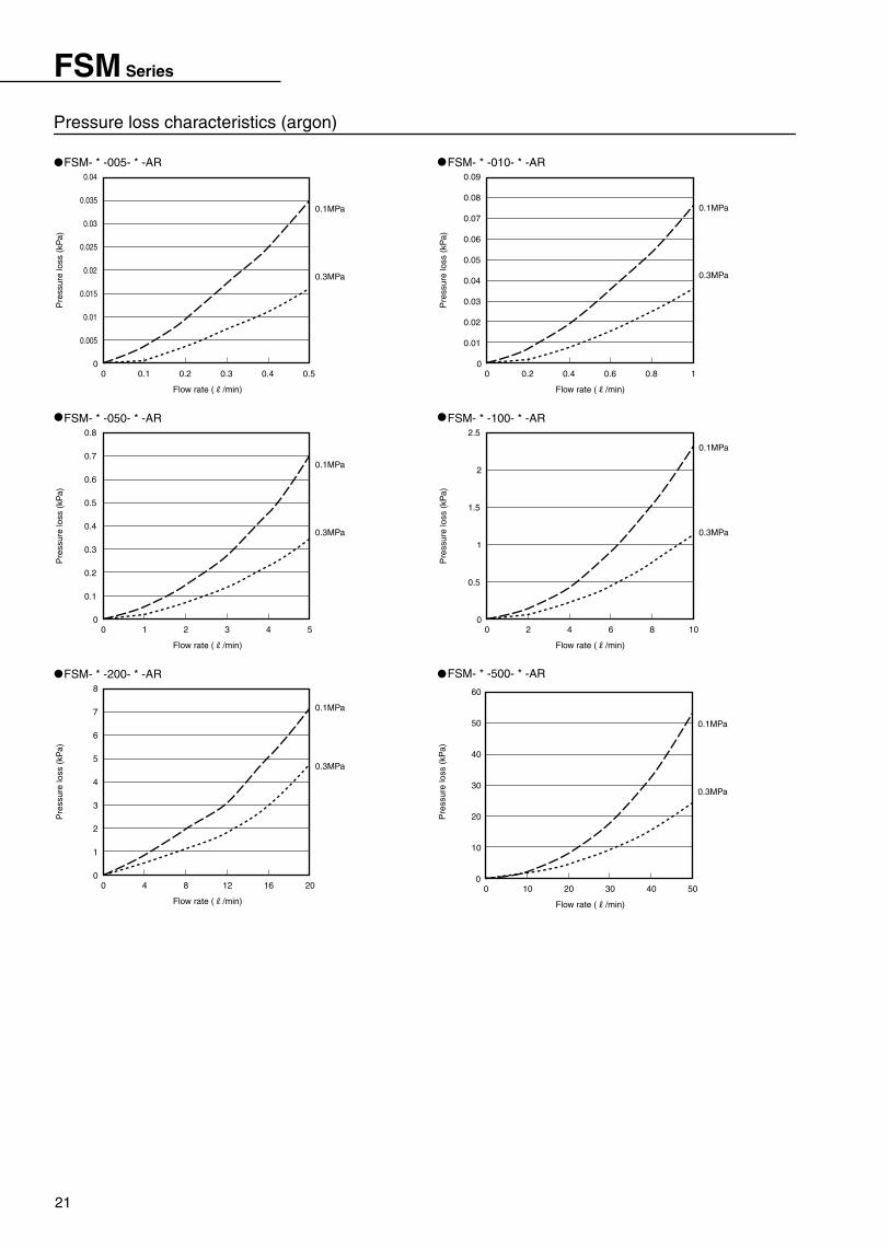
Pressure loss characteristics (argon)
22
How to operate
FSM Series
Pre
ssur
e lo
ss (
kPa)
0.1MPa
0.3MPa
1
0.005
0.01
0.015
0.02
0.03
0.025
0.035
0.04
0.045
0
Flow rate (R/min)
0.80.60.40.20
FSM- * -010- * -CO2
Pre
ssur
e lo
ss (
kPa)
0.1MPa
0.3MPa
10
0.5
1
1.5
2.5
2
0
Flow rate (R/min)
86420
FSM- * -100- * -CO2
Pre
ssur
e lo
ss (
kPa)
0.1MPa
0.3MPa
20
1
2
3
4
5
6
9
7
8
10
0
Flow rate (R/min)
1612840
FSM- * -200- * -CO2
Pre
ssur
e lo
ss (
kPa)
0.1MPa
0.3MPa
5
0.1
0.2
0.3
0.4
0.5
0.6
0.7
0
Flow rate (R/min)
43210
FSM- * -050- * -CO2
Pre
ssur
e lo
ss (
kPa)
0.1MPa
0.3MPa
50
10
20
30
40
50
60
0
Flow rate (R/min)
403020100
FSM- * -500- * -CO2
Pre
ssur
e lo
ss (
kPa)
0.1MPa
0.3MPa
0.5
0.005
0.01
0.015
0.02
0.025
0
Flow rate (R/min)
0.40.30.20.10
FSM- * -005- * -CO2
Pressure loss characteristics (carbon dioxide)

23
FSM-H・FSM Series
Separate indicator type
Display integrated type (common for FSM-H/FSM series)
3-digit LED display
• Data of CH1 is displayed in turn when displaying flow rate.• The maximum value is displayed during peak hold operation.• A mode is determined when selecting the mode.• Used for count-up when setting each data.
1 (UP) key
• Data of CH2 is displayed in turn when displaying flow rate.• The minimum value is displayed during peak hold operation.• Used for count down when setting each data.
2 (DOWN) key
Output (OUT2) display
• Light turned on when CH1 output turned on• Flash when overcurrent detected
Output (OUT1) display
• Light turned on when flowing reversely
Minus display [excluding FSM (for compressed air or nitrogen)]
• Used when entering various setting modes.• Used when returning to flow rate display.• Used when releasing peak hold operation.
MODE key
• Light turned on when displaying flow rate.• Flash when peak hold operation.• Light turned off depending on setting mode.
RUN display
*In FSM-H series, the design of front sheet differs. Same names and functions of display/controls are used.
Refer to Page 37 to 40 for names, functions and operations of display/controls.
Overflow indication
Name and functions of display/controls
• If the limit of 3-digit display is reached, the display will be lighted to show " ".
(This " " will be lighted when 10.00R/min, then 3-digit LED show 0.00.)
• The flow rate/various switches' setpoints, etc., are displayed.
• If of overflow, is displayed.
• If of the reverse direction overflow, is displayed.
(FSM [for compressed air or nitrogen] excluded)
• Light turned on when CH2 output turned on• Flash when overcurrent detected

24
How to operate
FSM-H・FSM Series
OFF setpoint
The output is turned off not depending on ON or OFF setpoint.
ON setpoint
Flow rateOFF
ON
Flow rateOFF
ON
1%F.S. and over
OFF setpointON setpoint
Flow rateOFF
ON
OFF setpoint ON setpoint
Flow rate
OFF setpointON setpoint
- +
- +
- +
- +
1%F.S.
OFF
ON
OFF
1%F.S.
1%F.S. and over
3%F.S. and over
3%F.S. and over
- +Flow rate
ON
Switch output function
Switch output OFF
Hysteresis operation 2
(Flow rate large side ON)
Hysteresis operation 1
(Flow rate small side ON)
Window operation 2
(Range out ON)
Window operation 1
(Range inside ON)
Operation waveformLED displayOperation pattern name
Switching mode
Operation
Note 1.Maintain intervals more than 3%F.S. between two setpoints during window operation.Hysteresis of 1%F.S. is provided on both ON and OFF sides automatically.
Note 2.Maintain intervals more than 1%F.S. between two setpoints when hysteresis operation.If the differential between 2 setpoints above is not maintained, it may result in not operated or unstable operation.
Note 3.If a switch is activated in unstable flow rate state such as a fluid pulsation, etc., unstable operation may be provided.In this case, maintain the difference between two setpoints satisfactorily, use the product after checking that switching is stabilized.
Note 4.In operation waveform, left shows the minus side, while, right shows the plus side.
Note 5.If waveform pattern is decided, magnitude of ON and OFF setpoints is decided, and the reverse magnitude is not allowed.However, in this product, operation with the specified operation pattern has precedence over all things.When the two setpoints are inputted, the magnitude is identified automatically, processing each identification properly as ON or OFF setpoint.As result, even if ON or OFF setpoint is inputted reversely, re-recognized as correct ON or OFF setpoint, always operating with the specified operation pattern.
ON sideFlash OFF side
Flash
Setpoint verification method
Press simultaneously.
Operation waveform display
Model number displayZero point adjustment value display
[AdJ] display
OFF setpoint display
ON setpoint displayOperation waveform display
Being held down.
Zero point adjustment value/model number display
CH2 data display
Being held down.
CH1 data display
(FSM [for compressed air or nitrogen] excluded)
Zero point adjustment value and model number display are displayed alternately.Switching is not affected even during operation.
If each key is pressed down with flow rate displayed, switch data ON or OFF setpoint/operation waveform, zero adjust value and the model are displayed to check.Switching is not affected during this operation.

25
FSM-H・FSM Series
How to operate each function
CH2: OFF setpointCH2: ON setpointCH2: operation pattern
CH1: OFF setpointCH1: ON setpointCH1: operation pattern
Bottom value displayed
Flash
Being held down.
Bottom value [453]
Peak magnitude displayed
Flash
Being held down.
Peak hold operation start(RUN light flash)
Peak magnitude [475]
Flow rate display state[460] displayed
Press simultaneously.
Refer to Page 26 for the operation (FSM [for compressed air or nitrogen] excluded).0 point adjustment function
Deviation of the display from 0 is corrected without flow.
Refer to Page 26 for the operation.Forcible output function
Switch output is turned on forcibly to check wiring connection and initial operation of input unit.
(Note) This test function is to be used to check wiring and operation of input unit.
Avoid using this function to run sequence program instead of actual signals, while machinery and equipment are being operated.
Refer to Page 26 for the operation.Switch output function
Having 2 pieces of switch output, 4 operation patterns and stop of operation can be set.
Setting the required operation pattern and the two setpoints (ON and OFF setpoints) defining operating points allows the switch function to start.
First determine operation pattern and ON and OFF setpoints to be used before setting work.
Select and set next data to operate a switch.
Peak hold function
Maximum and minimum flow rate values during the specified period can be read.
Use this setpoint when checking instantaneous flow rate change.
Also, peak hold operation never affects the basic function of this product such as switching and flow rate display, etc.
(Note) Above setting and tests affect output signals and indicated values seriously.Always stop machinery and equipment using this product, then check that the safety is secured, even if malfunction or wrong display is occurred, before starting operation.Handling during operation may produce an accident, malfunction and wrong display, causing a danger.

26
How to operate
FSM-H・FSM Series
Press once.Set same as switch CH1.
Switch CH2ON/OFF data setting
Press once.
Adjusted value reading
Press simultaneously.
Press once.
Press once.
FSM(Air/nitrogen)To flow rate display
Always adjust 0 point without flow.Caution
0 point adjustment value display
[AdJ] display
To flow rate display
To flow rate display
To flow rate display
0 point adjustment mode (FSM [air and nitrogen] excluded)
Press once.
Press once.
Press once.
Number change by up/down key
Switch CH1ON/OFF data setting
Switch CH2Operation mode change
Switch output forcible ON mode
Press once.
Alternate display
Alternate display
Alternate display
Operation mode change by up/down key
Alternate display
Determination
Determination
Determination
Press once.Press once.
Pressed once.
Flash
CH2 output ON
Being held down.
CH1 output ON
Being held down.
Data readingCount-down
Count-up
Data return
Press simultaneously.Press simultaneously.
Data setting of switch output function
Basic key operation
It is effective in the switching pattern setting/ON/OFF setpoint/0 adjustment mode.
Press once.
Setpoint displaySetpoint displayOperation mode display
OFF point waveform display
ON point waveform displayChannel 1 display
Switch CH1Operation mode change
[Flow rate display]
Flash
Flash
Flash
Flash
Separate.
Press once.
Being held down.
Switch output function/forcible output function/0 point adjustment operation
If the key is not operated longer than two seconds before confirming mode, the display will be returned to the flow rate display for safety.
key is further
pushed, the display will return to flow rate display.

27
Miniature flow sensorAnalog output type/switch output
FSM-V Series (Air/nitrogen gas)
Flow rate range:±0.05, ±0.1, ±0.5, ±1, ±5, ±10R/min
Note 4
Output
FSM-V-D / -R1000FSM-V-D / -R0500FSM-V-D / -R0100FSM-V-D / -R0050FSM-V-D / -R0010FSM-V-A-R1000FSM-V-A-R0500FSM-V-A-R0100FSM-V-A-R0050FSM-V-A-R0010FSM-V-A-R0005
FSM-V-D / -R0005
Separate indicator
DescriptionsModel no.
Flow rate display (7 segments 3-digit orange) and operation switch output (orange)
DC12/24V (10.8 to 26.4V)
50mA or less (indicator only)
ø3.7 0.2mm2 X 5-conductor (1m)
Flow rate display, flow rate display- peak hold, switch output and analog output
0 to 50 ˚C and 85%RH or less (to be no dew condensation.)
IEC standards IP40
EN55011, EN61000-6-2, EN61000-4-2/3/4/6/8
Approximate 70 (including lead wire 1m)
Available analog output type model no.
Display
Power supply voltage
Current consumption
Lead wire
Functions
Ambient temperature/humidity
Protective structure
EMC directive
Mass g
Separate indicator specifications (analog output type only) Note 7
ø2.6 0.15mm2 X 4-conductor (3m)ø2.6 0.15mm2 X 3-conductor (3m)
±2%F.S. or less±1%F.S. or less
Power display (green) and switch output (yellow)
Switch output 2 points Note 3
(NPN or PNP open collector output and PLC/relay)
±2%F.S. or less
Power display (green)
Analog output 1 point Note 2
(1-5V voltage output and connected load impedance 50K Ω and over)
±5%F.S. or less (0.1MPa, 25 ˚C and flow rate range ±100%F.S.)
±5%F.S. or less (-0.09 to 0.2MPa, 0.1MPa criteria)
±0.2%F.S./˚C or less (15 to 35 ˚C, 25 ˚C criteria)
Collet nozzleø0.3 nozzleø0.2 nozzleø0.1 nozzleCollet nozzleø0.3 nozzleø0.2 nozzleø0.1 nozzle
FSM-V- /-R0010
Analog
outpu
t accur
acyIns
tallat
ionW
orki
ng c
ondi
tions
Protective structure
Vibration resistance
EMC directive
Mass g
Response time
Power supply voltage
Current consumption
Lead wire
Output
Display
Flow rate range (R/min)
Note 7: A separate indicator is analog output type only. Care must be taken since switch output type can not be connected.
Note 1: Refer to Page 2 for compressed air quality class in accordance with JIS B 8392-1: 2000.Note 2: Analog output shows 3V when flow 0, while viewing the body with lead wire on the right side, the output will shift to 5V sides. If of reverse flow, the output shift to 1V side.Note 3: Switch output is 1 boundary value identification method with fixed hysteresis, and can be set by turning trimmer within the total flow rate range. Also, operation modes of OUT1 and OUT2 are reverse.Note 4: The specified F.S. (full scale) shows flow rate range. For example, F.S. with flow rate range: -10 to +10R/min, shows 20R/min.Note 5: The response time may change depended with piping condition.Note 6: When using this product for adsorption verification, always install an air filter (filtration rating 30 µ m or less) to prevent suction of foreign materials between adsorption nozzle and this product.
Also, when compressed air is used, always install a filter (for drain removing) on the primary side (upstream).
FSM-V- /-R1000
FSM-V- /-R0500
FSM-V- /-R0100
FSM-V- /-R0050
FSM-V- /-R0005
FSM-V-A-R1000
FSM-V-A-R0500
FSM-V-A-R0100
FSM-V-A-R0050
FSM-V-A-R0010
-10 to +10-5 to +5-1 to +1-0.5 to +0.5-0.1 to +0.1-0.05 to +0.05-10 to +10-5 to +5-1 to +1-0.5 to +0.5-0.1 to +0.1-0.05 to +0.05
FSM-V-A-R0005
Switch output typeAnalog output type
Descriptions
Model no.
Clean air (JIS B 8392-1.1.2 to 5.6.2), compressed air (JIS B 8392-1.1.2 to 1.6.2) Note 1 and nitrogen gas
0.2
-0.1
0.3
0 to 50 and 90%RH or less (to be no dew condensation.)
0 to 50
5ms or less (when sensor discrete/final arrival output voltage reaches 90%.) Note 5
DC12/24V (10.8 to 26.4V)
30mA or less
Both vertical and horizontal
Not required
IEC standards IP40
10 to 150Hz, compound amplitude 1.5mm, maximum 10G and each XYZ directions 2 hours
EN55011, EN61000-6-2, EN61000-4-2/3/4/6/8
Approximate 8 (excluding lead wire and joint)
Working fluid
Maximum working pressure MPa
Minimum working pressure MPa
Withstanding pressure MPa
Ambient temperature/humidity ˚C
Working fluid temperature ˚C
Linearity
Pressure characteristics
Temperature characteristics
Repeatability
Installation attitude
Installation strait piping section
Sensor body specifications
N P N P N P N P N P N P
NP
NP
NP
NP
NP
NP
Switch output 2 points(NPN or PNP open collector output, load current 50mA or less voltage drop 2.4V and PLC/relays)
Analog output 1 point(1-5V voltage output and connected load impedance 50KΩ and over)
(References) Applicable nozzle of suction-separation application

28
How to order
FSM-V Series
*Refer to Page 35 to 40 for the operation dimensions, etc.
Bracket kit
KL-D
A Bracket kitSingle foot bracket (radial installation)
Both sides foot brackets (parallel)
Panel mount bracket set cover attached
Operation protective cover
KL-D
KD-D
KHS-D
KC
PPD3ContentSymbol
Bracket for separate indicator
A
Switch output type
B Flow rate range±0.05R/min
±0.1R/min
±0.5R/min
±1R/min
±5R/min
±10R/min
R0005
R0010
R0050
R0100
R0500
R1000
R0050
A Switch output typeNPN output
PNP output
N
P
NV DFSM
Model no.
Flow rate rangeB
ContentSymbol
Separate indicator (analog output type only)
A
Output type
E Joint typeAxial ø1.8 fiber tube
Axial ø4 push in
Radial ø4 push in
Port size M5
H2
H4
HL4
M5
D Flow rate range±0.05R/min
±0.1R/min
±0.5R/min
±1R/min
±5R/min
±10R/min
R0005
R0010
R0050
R0100
R0500
R1000
C Lead wire length3m3
B Lead wire outlet directionAxial
Radial
H
V
H2R0005
A Output typeAnalog output
Switch output (NPN)
Switch output (PNP)
A
N
P
3HV AFSM
Model no.
Joint typeE
Flow rate rangeD
Lead wire lengthC
Lead wire outlet directionB
ContentSymbol
Sensor body
How to order
A
*Refer to Page 35 and 36 for bracket dimensions and installation dimensions.

29
FSM-V Series
Refer to Page 35 for internal structure drawing.
121415
13
16
11
10
6 8 9 2
17
3
4
5
Separate indicator FSM-V-D * -R *
FSM-V-**3-R*-M5/analog output type(Switch output type uses same internal structure.)
Material
Glass epoxy resin
Halogen-free polyethylene resin mixture
Stainless steel
Stainless steel
Aluminum alloy
Nitrile rubber
Stainless steel
Polyester film
Parts name
Electron circuit board
Lead wire
Rectifier
Filter
Cartridge joint (M5)
O ring
Joint fixing pin
Front sheet
No.
9
10
11
12
13
14
15
16
Material
PBT (glass fiber 30%)
PBT (glass fiber 30%)
PBT (glass fiber 30%)
Nitrile rubber
Aluminum alloy
Nitrile rubber
Silicon
Iron steel (galvanization)
Parts name
Body
Case
Lead wire holder
Bush
Bush holder
Sensor gasket
Sensor tip
P tight screw
No.
1
2
3
4
5
6
7
8
Internal structure and parts list

30
MEMO

31
FSM-V Series
2-ø3.2 penetrating 2-ø3.2 penetrating
2.3
17
2.3
17
3333
(51.8)(51.8)
ø2.
6
7
10
17
ø2.6
717
10
2-ø3.2 penetrating 2-ø3.2 penetrating
2.3
17
2.3
17
3333
(45.8) (45.8)
ø2.
6
7
10
17
ø2.6
717
10
Dimensions (common for analog and switch output types)
FSM-V- * H3-R * -H4(Axial lead wire and axial ø4 push in)
FSM-V- * H3-R * -H2(Axial lead wire and axial ø1.8 fiber tube)
FSM-V- * V3-R * -H4(Radial lead wire and axial ø4 push in)
FSM-V- * V3-R * -H2(Radial lead wire and axial ø1.8 fiber tube)

32
Dimensions
FSM-V Series
2-ø3.2 penetrating 2-ø3.2 penetrating
2.3
17
2.3
17
3333
(45)(45)
ø2.
6
7
10
17
ø2.6
717
10
2-ø3.2 penetrating 2-ø3.2 penetrating
2.3
17
2.3
17
3333(2
1.5)
(58.6)
(21.
5)
(58.6)
ø2.
6
7
10
17
ø2.6
717
10
Dimensions
FSM-V- * H3-R * -M5(Axial lead wire and port size M5)
FSM-V- * H3-R * -HL4(Axial lead wire and radial ø4 push in)
FSM-V- * V3-R * -M5(Radial lead wire and port size M5)
FSM-V- * V3-R * -HL4(Radial lead wire and radial ø4 push in)

33
FSM-V Series
-0.05MPa
0.1MPa
0.2MPa
-0.05MPa
0.1MPa
0.2MPa
-0.05MPa
0.1MPa
0.2MPa
-0.05MPa
0.1MPa
0.2MPa
-0.05MPa
0.1MPa
0.2MPa
-0.05MPa
0.1MPa
0.2MPa
Pre
ssur
e lo
ss (
kPa)
10
2
4
6
8
10
12
14
16
0
Flow rate (R/min)
86420
Pre
ssur
e lo
ss (
kPa)
5
1
2
3
4
5
6
0
Flow rate (R/min)
43210
Pre
ssur
e lo
ss (
kPa)
1
0.05
0.1
0.15
0.2
0.25
0.3
0.35
0.4
0.45
0.5
0
Flow rate (R/min)
0.80.60.40.20
Pre
ssur
e lo
ss (
kPa)
0.5
0.02
0.04
0.06
0.08
0.1
0.12
0.14
0.16
0.18
0
Flow rate (R/min)
0.40.30.20.10
Pre
ssur
e lo
ss (
kPa)
0.1
0.01
0.02
0.03
0.04
0.05
0.06
0.07
0.08
0.09
0.1
0
Flow rate (R/min)
0.080.060.040.020
Pre
ssur
e lo
ss (
kPa)
0.05
0.005
0.01
0.015
0.02
0.025
0.03
0.035
0.04
0.045
0.05
0
Flow rate (R/min)
0.040.030.020.010
FSM-V- * -R1000-H4
*If fiber tube is used, pressure loss may increase depending on piping condition.
FSM-V- * -R0500-H4
FSM-V- * -R0100-H4FSM-V- * -R0050-H4
FSM-V- * -R0010-H4FSM-V- * -R0005-H4
Analog output characteristics
Pressure loss characteristics
Nozzle diameter ø0.2
Nozzle diameter ø0.25
Nozzle diameter ø0.3
Flow rate ( /min)
][ Pipe diameter: ø4Pipe length (nozzle to vacuum source): 0.3m
Ana
log
outp
ut (
V)
10.80.60.40.20-0.2-0.4-0.6-0.8-1
6
5
4
3
2
1
0
Analog output data (e.g.)
When not suckedVoltage level
Adsorption timeVoltage level
Out
put (
V)
Time (mS)3020100
4.2
4.0
3.8
3.6
3.4
3.2
3.0
2.8
Response time (example of suction and separation)
FSM-V-A-R0100
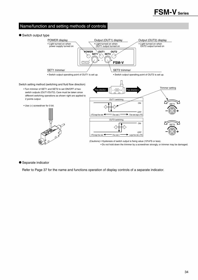
34
FSM-V Series
Refer to Page 37 for the name and functions operation of display controls of a separate indicator.
Separate indicator
Switch output typeOutput (OUT2) displayOutput (OUT1) display
• Switch output operating point of OUT2 is set up.
SET2 trimmer
• Switch output operating point of OUT1 is set up.
SET1 trimmer
POWER display
Name/function and setting methods of controls
SET2
SET1
Large flow rate (+FS)(-FS) large flow rateOFF
ON
Flow rate 0
OUT2 switching
Flow rate large (+FS)(-FS) large flow rateOFF
Trimmer setting
ON
Flow rate 0
OUT1 switching
Flow direction +Flow direction -
(Cautions) • Hysteresis of switch output is fixing value (10%FS or less).• Do not hold down the trimmer by a screwdriver strongly, or trimmer may be damaged.
Switch setting method (switching and fluid flow direction)
- +- +
SET2SET1OUT2OUT1POWER
FSM-V
• Light turned on when power supply turned on
• Light turned on when OUT1 output turned on
• Light turned on when OUT2 output turned on
• Turn trimmer of SET1 and SET2 to set ON/OFF of two switch outputs (OUT1/OUT2). Care must be taken since different switching operations as shown right are applied to 2 points output.
• Use (+) screwdriver for 0 bit.

35
Separate indicator FSM-H-D * Series(FSM-H)
FSM-A-D * Series(FSM-A)
FSM-V-D * Series(FSM-V)
FSM-H-D * - * FSM-A-D * - * FSM-V-D * - * (separate indicator) 11
10
9
8
7
65
4
3
2
1
Material
PBT (glass fiber 30%)
Glass epoxy resin
Glass epoxy resin
Glass epoxy resin
Polyvinyl chloride
Brass/nickeling
PBT (glass fiber 15%)
PBT (glass fiber 30%)
Polyamide/copper alloy (plating)
Aluminum
Polyester film
Parts name
Case top
Display circuit board
CPU circuit board
Sensor circuit board
Lead wire (1m)
Screw
Rear side cover
Case medium
Gland
Shield sheet
Surface sheet
No.
1
2
3
4
5
6
7
8
9
10
11
Internal structure and parts list
2-M3
1818
7.5
15
32
(P tight)2-nominal 3
25
Tapped mounting hole machining drawing
30 32
ø3.7 5-conductorCable length 1m
22
Sensor gland
2-ø2.7 depth 7
SVOUT2
MODE
RUN OUT1
L/min1 2
FSMG
Bracket dimensions
This bracket can be installed per 90 deg. increment against the switch body.Determine the installation attitude according to the location.
Single foot bracket attached (PPD3-KL-D)*L type bracket and 2 setscrews
Dimensions
FSM-H-D * - * FSM-A-D * - * FSM-V-D * - *

36
Dimensions
FSM- -D * Series
HAV
37.5 (2.5)
Protective cover Protective cover holder
52
39
Panel vessel
Panel holder
Cover
33.5 ±0.3
32
29.5
5
Plate thickness t0.8 to 6
(Mou
nting
pitc
h 40
and
over
)
GV S
Panel hole machining Fig.(Mounting pitch 53 and over)
Lead wire through hole
4-M3
18
50
(P tight)2-nominal 3
83230
62 50
18
Tapped mounting hole machining drawing
Note: A combination with PPD3-KHS-D is not available.
Operation protective cover attached (PPD3-KC)*Protective cover and its holder
Panel mount bracket set with cover (PPD3-KHS-D)*Panel vessel, holder, key and cover.
This bracket can be installed per 90 deg. increment.Determine the installation attitude according to the location.
Bracket dimensions
Both sides foot brackets attached (PPD3-KD-D)*D type bracket and 2 setscrews
For panel holder, the installation attitude can be changed per 90 deg. increment.

37
Common for all FSM series
• If the limit of 3-digit display is reached, light will be turned on and be shown.
(In 10.00R/min, this is turned on to display 0.00 with 3-digit LED.)
• Light turned on when CH2 output turned on
• Flash when overcurrent detected
• Flow rate, various switches setpoints, etc or status are displayed.
• If of overflow, will be displayed.• If of the reverse direction overflow, will be displayed.
• Data of CH2 is displayed in turn when displaying flow rate.
• The minimum value is displayed during peak hold operation.
• Determine a mode when selecting the mode.• Used for count-down when setting each data
• Light turned on when flowing reversely
Minus display
Overflow indication (excluding FSM-V-D * )
3-digit LED display
• Data of CH1 is displayed in turn when displaying flow rate.• The maximum value is displayed during peak hold operation.• Determine the mode when selecting the mode.• Used for count-up when setting each data
1 (UP) key
2 (DOWN) key
Output (OUT2) display
• Light turned on when CH1 output turned on• Flash when overcurrent detected
Output (OUT1) display
• Light turned on when displaying flow rate.• Flash when peak hold operation.
RUN display
• Used when entering various setting modes.• Used when advancing setting mode.• Used when returning to flow rate display.• Used when releasing peak hold operation.
MODE key 2R/min
OUT2OUT1
1MODE
RUNFSM
1
Separate indicator type (FSM-H-D/FSM-A-D/FSM-V-D common)
*In FSM-H series, the design of front sheet differs. Name and functions of same display/controls are used.
Name and functions of display/controls

38
How to operate
Common for all FSM series
OFF setpoint
The output is turned off not depending on ON and OFF setpoints.
ON setpoint
Flow rateOFF
ON
Flow rateOFF
ON
1%F.S. and over
OFF setpointON setpoint
Flow rateOFF
ON
OFF setpoint ON setpoint
Flow rate
OFF setpointON setpoint
- +
- +
- +
- +
1%F.S.
OFF
ON
OFF
1%F.S.
1%F.S. and over
3%F.S. and over
3%F.S. and over
- +Flow rate
ON
Switch output function
Switch output OFF
Hysteresis operation 2
(Flow rate large side ON)
Hysteresis operation 1
(Flow rate small side ON)
Window operation 2
(Range out ON)
Window operation 1
(Range inside ON)
Operation waveformLED displayOperation pattern name
Switching mode
Operation
Note 1.Maintain intervals more than 3%F.S. between two setpoints during window operation.Hysteresis of 1%F.S. is provided on each ON and OFF sides automatically.
Note 2.Maintain intervals more than 1%F.S. between two setpoints when hysteresis operation.
Note 3.If the differential between above 2 setpoints is not satisfied, it may result in not operated or unstable operation.If a switch is activated in unstable flow rate state such as a fluid pulsation, etc., unstable operation may be provided.In this case, maintain the difference between two setpoints satisfactorily, use the product after checking that switching is stabilized.
Note 4.In operation waveform, left side shows minus side, while, right shows plus side.
Note 5.If waveform pattern is decided, magnitude of ON and OFF setpoints is decided, and the reverse magnitude is not allowed.However, in this product, operation with the specified operation pattern has precedence over all things.When the two setpoints are inputted, the magnitude is identified automatically, processing the proper identification as ON and OFF setpoints.As result, even if ON and OFF setpoints are inputted reversely, re-recognized as correct ON and OFF setpoints, always operating with the specified operation pattern.
ON sideFlash OFF side
Flash
Setpoint verification method
Press simultaneously.
Operation waveform display
Model number display0 point adjustment value display[AdJ] display
OFF setpoint display
ON setpoint displayOperation waveform display
Being held down.
0 point adjustment value/model number display
CH2 data display
Being held down.
CH1 data display
Zero point adjustment value and model number display are displayed alternately.
Switching is not affected even during operation.
If each key in flow rate display state is pressed down, switch data ON and OFF setpoints, operation waveform,
zero adjust value and models are displayed to check.
Switching is not affected during this operation.

39
Common for all FSM series
Operation of each function
CH2: OFF setpointCH2: ON setpointCH2: Operation pattern
CH1: OFF setpointCH1: ON setpointCH1: Operation pattern
Bottom value displayed
Flash
Being held down.
Bottom value [453]
Peak magnitude displayed
Flash
Being held down.
Peak hold operation start(RUN light flash)
Peak magnitude [475]Flow rate display condition[460] displayed
Press simultaneously.
Refer to Page 40 for the operation.0 point adjustment function
Deviation of the display from 0 is corrected without flow.
Refer to Page 40 for the operation.Forcible output function
Switch output ON forcibly, used for initial operation checking of wiring and input unit.
(Note) Use this test function for confirming wiring and action of input unit.
Avoid using this function instead of actual signals to run sequence program, while machinery and equipment are operated.
Refer to Page 40 for the operation.Switch output function
Having 2 pieces of switch output, 4 operation patterns and stop of operation can be set.
Setting the required operation pattern and two setpoints (ON and OFF setpoints) that defines operating points allows the switch function to start.
First determine operation pattern and ON and OFF setpoints to be used before setting work.
Select and set next data to operate a switch.
Peak hold function
Maximum and minimum values indicated with flow rate value can be read during the specified period.
Use this function when checking instantaneous flow rate change.
Also, peak hold operation never affects the basic function of this product such as switching and flow rate display, etc.
(Note) Above setting and tests affect output signal and indicated value seriously.Always stop machinery and equipment using this product, and check that the safety is secured, even if malfunction/wrong display could be produced, then start the operation.Handling during operation may produce an accident, malfunction and wrong display, causing a danger.

40
How to operate
Common for all FSM series
[Flow rate display]
Press once.Set same as a switch CH1.
To flow rate display
Adjusted value reading
Press simultaneously.
Press once.
Press once.
Always adjust 0 point without flow.Caution
0 point adjustment value display
[AdJ] display
To flow rate display
0 point adjustment mode
Determination
Press once.
Press once.
To flow rate display
Press once.
Number change by up/down key
Switch output forcible ON mode
Determination
Press once.
Alternate display
Alternate display
Alternate display
An operation mode change by an up/down key
AlternateDisplay
DeterminationPress once.Press once.
Press once.
Flash
CH2 output ON
Being held down.
CH1 output ON
Being held down.
Data readingCount-down
Count-up
Data return
Press simultaneously.Press simultaneously.
Data setting of switch output function
Basic key operation
It is effective in the switching pattern setting/ON/OFF setpoint/0 adjustment mode.
Press once.
Setpoint displaySetpoint displayOperation mode display
OFF point waveform display
ON point waveform displayChannel 1 display
Switch CH1ON/OFF data setting
Switch CH1Operation mode change
Flash
Flash
Flash
Flash
Separate.
Press once.
Being held down.
Switch output function/forcible output function/0 point adjustment operation
If the key operation is not done more than 2 seconds before confirming mode, the display will be returned to flow rate display for safety.
If key is
further pushed, the display will be returned to flow rate display.
Switch CH2ON/OFF data setting
Switch CH2Operation mode change

41
Common for all FSM series
2.5V
Voltage5V
V out
V out
R2
R1
TemperatureValue of resistance
R2R1
Symmetry of temperature distribution is lost.
2.5V
Voltage5V
V out
V out
R1 R2Rh
[With flow]Thermo sensor 1 FLOWThermo sensor 2
R1 R2
Heater
Rh
TemperatureValue of resistance
R2
R2
R1
R1
Temperature distribution symmetry
[Without flow]
In FSM-H, FSM (argon and carbon dioxide) and FSM-V series, applying silicon micro machining technology, platinum sensor tip (3mm X 3.5mm) is used.
Sensor section is insulated from the silicon substrate thermally, and quick response and high sensitivity are achieved since heat capacity is very small.
In sensor section, two thermo sensors are located over the heater. Platinum is used as the material of thermo sensor, changing value of resistance in
accordance with temperature. Energizing the heater, if there is no flow, temperature distribution will be spreaded as symmetry from the center of the heater. If
there is flow, the symmetry will be lost and the temperature of upstream will decrease, and the temperature of downstream will increase. This difference of
temperature will be converted as difference of resistance of the thermo sensor, changing per flow rate. If of reverse flow, the difference of temperature (the
difference of resistance) will be reverse. If this method is used, the flow rate in both directions can be detected. This method is appropriate for detection of
relatively small flow rate.
Measurement principle of FSM-H, FSM (argon and carbon dioxide) and FSM-V series
Ambient temperature sensor
Heater
Electrode
Bridge circuit
Platinum sensor tip
Ambient temperature sensor
Heater
Sensor tip
3mm
FLOW
7mm
Vout-
+
In FSM (air and nitrogen gas) series, applying silicon micro machining technology, platinum sensor tip (3mm X 7mm) is used. Heater section is insulated from the silicon substrate thermally to achieve quick
response and high sensitive since heat capacity is very small.
Building the bridge that includes heater and ambient temperature sensors as figures, the temperature is controlled as the temperature difference between ambient temperature sensor and heater is constant.
Platinum is used as a material of heater, changing value of resistance in proportion to temperature change. If an gas flows, output of bridge circuit increases in proportion to flow rate to compensate the heat
lost from the heater (to maintain the constant temperature difference). Using this control method, the detection not affected with temperature or pressure change is possible. This control method is appropriate
for the detection of relatively large flow rate.
Measurement principle of FSM (air and nitrogen gas) series
Technical data

42
Common for all FSM seriesTechnical data
Acoustic
Acoustic
Acoustic
Subsonic
Subsonic
Subsonic
Subsonic
Subsonic
Subsonic
Subsonic
Subsonic
Subsonic
Acoustic
Acoustic
Acoustic
Acoustic
Acoustic
Acoustic/subsonic
velocity
0
0
0
0
0
0
0
0.01
0.02
0.04
0.06
0.08
0.1
0.2
0.3
0.4
0.5
-0.07
-0.06
-0.05
-0.04
-0.03
-0.02
-0.01
0
0
0
0
0
0
0
0
0
0
P1(MPa)
Gauge pressure
P2(MPa)
Gauge pressure
0.0313
0.0413
0.0513
0.0613
0.0713
0.0813
0.0913
0.1013
0.1013
0.1013
0.1013
0.1013
0.1013
0.1013
0.1013
0.1013
0.1013
P2(MPa)
Absolute pressure
0.1013
0.1013
0.1013
0.1013
0.1013
0.1013
0.1013
0.1113
0.1213
0.1413
0.1613
0.1813
0.2013
0.3013
0.4013
0.5013
0.6013
P1(MPa)
Absolute pressure
Blo
w (
leak
age
insp
ectio
n)S
uctio
n
36.0070
36.0070
36.0070
35.2020
32.8780
28.6660
21.4800
22.6260
31.9980
45.2520
55.4230
63.9960
71.5520
107.096
142.641
178.186
213.731
ø220.2540
20.2540
20.2540
17.2490
16.1100
14.0460
10.5250
11.0870
15.6790
22.1740
27.1570
31.3580
40.2480
60.2420
80.2360
100.230
120.224
ø1.59.0020
9.0020
9.0020
8.8000
8.2200
7.1660
5.3700
5.6570
8.0000
11.313
13.856
15.999
17.888
26.774
35.660
44.547
53.433
ø14.4110
4.4110
4.4110
4.3120
4.0280
3.5120
2.6310
2.7720
3.9200
5.5430
6.7890
7.8400
8.7650
13.119
17.474
21.828
26.182
ø0.72.2500
2.2500
2.2500
2.2000
2.0550
1.7920
1.3430
1.4140
2.0000
2.8280
3.4640
4.0000
4.4720
6.6940
8.9150
11.137
13.358
ø0.51.440
1.440
1.440
1.408
1.315
1.147
0.859
0.905
1.280
1.810
2.217
2.560
2.862
4.284
5.706
7.127
8.549
ø0.40.810
0.810
0.810
0.792
0.740
0.645
0.483
0.509
0.720
1.018
1.247
1.440
1.610
2.410
3.209
4.009
4.809
ø0.30.360
0.360
0.360
0.352
0.329
0.287
0.215
0.226
0.320
0.453
0.554
0.640
0.716
1.071
1.426
1.782
2.137
ø0.20.090
0.090
0.090
0.088
0.082
0.072
0.054
0.057
0.080
0.113
0.139
0.160
0.179
0.268
0.357
0.445
0.534
ø0.1
Calculated flow rate value (R/min)
PinholeP2: atmospheric pressure
P1: pressurization
P2: atmospheric pressure
P1: pressurization
Example of calculation
When diameter of a nozzle is between 0.1 to 2 and P2 is variable, the calculated flow rate values are shown as followings.
Adsorption nozzleP1: atmospheric pressure
P2: vacuum
This is a guide of flow rate range when using a flow sensor as the adsorption/separation verification with adsorption nozzle and leakage inspection, etc.
The flow rate can be calculated according to effective sectional area of a nozzle (pinhole) and differential pressure between inside and outside of nozzle.
For P1>1.89P2 (acoustic velocity)
Q=113.2 X S X P1
For P1 <1.89P2 (subsonic)
Q=226.4 X S X P2 (P1-P2)
Q : flow rate R/minP1 : primary side absolute pressure MPaP2 : secondary side absolute pressure MPaS : Ef. sec. area mm2 of nozzle (pinhole)
How to select flow sensor1
=
(Caution)
• If piping has a leakage, the actual flow will be larger than the calculated value. Please consider the leakage when selecting flow rate.
• If there is a narrower section than adsorption nozzle diameter in the midway of piping, flow rate will be restricted, so the value will be smaller than
the calculated value.
Also, adsorption verification, etc., could not be done.
• The effective sectional area is just reference. If the nozzle is elongated, the effective sectional area will be smaller than opening area of the nozzle.
• Response time is decided by capacity of pipe from adsorption nozzle (pinhole) to flow sensor. When detecting with high speed, reduce capacity in
pipe as placing a flow sensor near the adsorption nozzle.

43
Common for all FSM series
-0.3(R/min)
0.5(R/min)
0(R/min)
0.5(R/min)
A: ø4 X 1000 B: ø4 X 40
A: ø4 X 40 B: ø4 X 1000
A: ø4 X 40 B: ø4 X 40
A gas is released from pipe B inside.
Ana
log
volta
ge o
utpu
t (V
)
0.5
140013001200110010009008007006005004003002001000
1
1.5
2
2.5
3
3.5
4
4.5
5
5.5
A gas is filled in pipe B.
Vacuum source (-70kPa)
FSM-V
Time (msec)
Adsorption Release (blow) SuctionSuction
Pipe dependence of response
Test pipe
AA
Collet nozzle
Workpiece
Nozzle
A-A cross section
Pressure sensor3 way valve
BA
Nozzle (ø0.25)
Pressurization source (20kPa)
If collet nozzle is used.2
Collet nozzle is widely used to avoid direct contact of an absorbed workpiece to the
nozzle. The inside of collet nozzle is as a pyramid. When absorbing a workpiece, as
structure, some clearances are created in four corners, creating a leakage. If the
effective sectional area of pipe (including valve and joint, etc.) is smaller than the
gap (effective sectional area) between collet nozzle and workpiece, the flow rate is
decided according to effective sectional area of pipe, so flow rate differential when
adsorption or non-adsorption will be reduced. In this case, if the effective sectional
area of pipe is increased as large as possible than the effective sectional area of
gap between collet nozzle and workpiece, the adsorption verification is done
certainly.
Response time1
The response time of adsorption verification time is
decided by capacity of pipe and exhaust perfor-
mance of vacuum pump, etc.
For example, if of piping as right, pipe dependence
of response time is as the following. As the result, to
reduce the response time, it is effective that the in-
ner pipe volume from adsorption nozzle to the sen-
sor is reduced as small as possible.
Adsorption verification

44
Common for all FSM seriesTechnical data
Comparing to leakage of air (20 ˚C) and liquids
Ql/QaLiquid pressure PlAir pressure Pa , Pa•s
0.006
0.0006
0.02
0.4MPa
0.4MPa
15MPa
0.4MPa
0.4MPa
0.4MPa
0.001
0.01
0.01
Water 20 ˚C
Brake oil 50 ˚C
Brake oil 50 ˚C
Liquid
605
0.10.006
QR
Qa16.7 (mR/min)Qa==0.006
201.013 X 10⁵ 1.18 (mR/min)XQ=500 X
101.3 X Pl(101.3+Pa/2) X Pa
QIQa
X=
60T1.013 X 105 XQ=V X
E.g.) When workpiece of water leakage 0.1mR/min (applied pressure 0.4MPa) is tested with compressed air (applied pressure 0.4MPa), the leakage Qa is ...
E.g.) Where capacity of workpiece is 500mR, detecting time is 5sec., 20Pa of differential pressure is created, the leakage is ...
Q: leakage (mR/min) P: differential pressure (Pa) V: capacity of workpiece (mR) T: detecting time (s)
Coefficient of viscosity (Pa•s X 10-3)
26
10
7
1.00
0.55
0.40
0.0181
0.0195
0.0204
20 ˚C
50 ˚C
70 ˚C
Brake oil ( )Water ( )Air ( )Temperature
Qa : air leakage (mR/s)Ql : liquid leakage (mR/s) : air viscosity (Pa•s) : liquid viscosity (Pa•s)Pa : air applied pressure (kPa)Pl : liquid applied pressure (kPa)
Comparing to gas and liquid leakage2
When converted form a pressure gauge method, use the equation below to calculate leakage.
How to calculate leakage1
Leakage inspection
Use this ratio as reference when the leakage inspection is done with air to a workpiece for liquid.However, this equation is led from the Hagen Poiseuille's equation where the pinhole is a round tube, and the surface is smooth. Pinholes such as welding defective, etc., are not always applied to a logic equitation.
P

45
Common for all FSM series
Measuring sample
Check valve(By-pass)
Flow sensor
Measuring sample
2 way valve
2 way valve
2 way valve(Exhaust)
2 way valve(Exhaust)
2 way valve(By-pass)
[Example of system configuration]
Flow sensor
Filling time of workpiece3
If the content volume of a workpiece is large, time is consumed to fill
air until test pressure (TP) of the leakage inspection is reached. In
this case, filling time can be reduced by by-pass circuit using 2 way
or check valve, etc., as shown right.
When a 2 way valve is used, a 2 way valve can be open and closed
according to the flow rate of flow sensor. Filling is started, and
workpiece internal pressure is approaching to test pressure (TP),
causing flow rate to decrease. Closing a 2 way valve for by-pass
with this flow signal, measurement of a leakage is started.
When check valve is used, using a check valve with low cracking
pressure, the check valve opens until near test pressure (TP),
reducing filling time.

46
FSM and FSM-V series only
Miniature inline filter
FSM-VFM Series
Note 2
Note 1: Refer to Page 2 for compressed air quality class in accordance with JIS B 8392-1: 2000.
Note 2: If the flow rate reaches 10R/min, pressure loss increases, so use the product below 10R/min.
4.25.2
ContentSymbol
B Attached
A Tube outside diameter
AttachedB
(Element: 5 pieces and joint fixing pin: 1 piece)
EVFMFSM
Maintenance part model no.(Cross headed bowl tapping screw M2.5 X 6: 1 piece)
Tube outside diameter
Model no.
No brackets
Bracket attached
Blank
B
ø1.8 (fiber tube)
ø4 (push in)
Port size M5
H22
H44
M55
BVFMFSM
Bracket part model no.
H44 BVFMFSM
How to order
A
Port size M5ø1.8
(Fiber tube)
Case
Element
FSM-VFM-M55FSM-VFM-H44FSM-VFM-H22DescriptionsClean air (JIS B 8392-1.1.2 to 5.6.2) and compressed air (JIS B 8392-1.1.2 to 1.6.2) Note 1
ø4
(Push in)
0.75
-0.1 to 0.5
0 to 50
Polyamide
Polypropylene and polyethylene
10
9.5
10
Working fluid
Applicable tube outer diameter
Withstanding pressure MPa
Working pressure range MPa
Ambient temperature range ˚C
Material
Filtration rating micron µm
Product mass g
Recommended flow rate R/min
Specifications
This is the inline filter for small flow sensor FSM,FSM-V series. Small capacity does not prevent high speed response when adsorption verification.
Miniature and space saving size Easy element replacement Case materials using polyamide resin with excellent chemical resistance. Due to transparent case, contamination of element can be checked from outside
Features
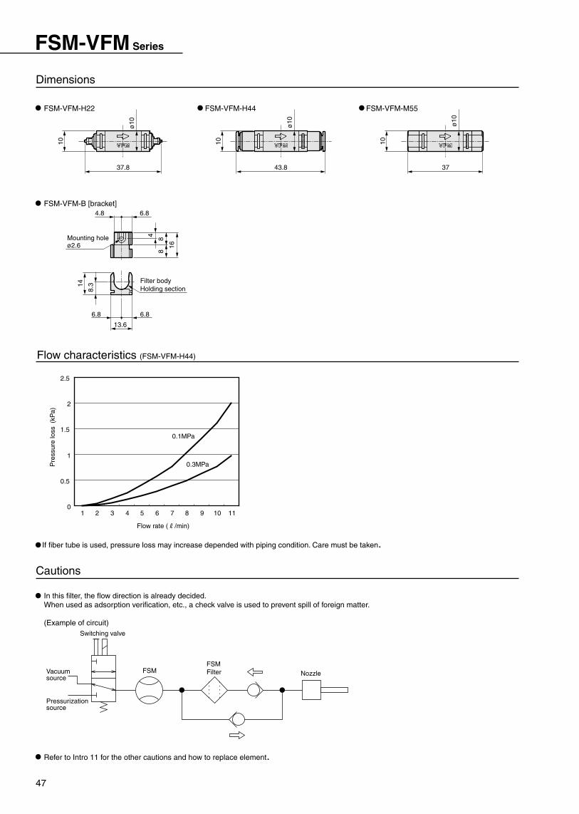
47
FSM-VFM Series
NozzleFSMFilterFSM
Pressurization source
Vacuum source
Switching valve
(kP
a)
0.3MPa
0.1MPa
Pre
ssur
e lo
ss
Flow rate (R/min)
1110987654321
2.5
2
1.5
1
0.5
0
Flow characteristics (FSM-VFM-H44)
ø2.6Mounting hole
6.84.8
16
884
14
8.3 Filter body
Holding section
13.6
6.86.8
10
37
ø10
43.8
10
ø10
ø10
37.8
10
Cautions
If fiber tube is used, pressure loss may increase depended with piping condition. Care must be taken.
Refer to Intro 11 for the other cautions and how to replace element.
In this filter, the flow direction is already decided.When used as adsorption verification, etc., a check valve is used to prevent spill of foreign matter.
(Example of circuit)
Dimensions
FSM-VFM-M55FSM-VFM-H44
FSM-VFM-B [bracket]
FSM-VFM-H22

48
ø8, ø10, ø12, R1/4, R3/8, Rc1/4, Rc3/8
Rc1/4, Rc3/8
-0.095 to 0.99MPa
-0.095 to 1.5MPa (compressed air)
-0.095 to 0.99MPa (N2)
Working pressure range
0.01 micron m
(Removal efficiency 99.99%)
Filtration rating
5 to 45 deg.
Port sizeModel no.
Resin type FCS1000
Stainless steel type
FCS1000-P9*
FCS1000 series
ø4, ø6, ø8, R1/8, R1/4
Rc1/8,Rc1/4
-0.095 to 0.99MPa
-0.095 to 1.5MPa (compressed air)
-0.095 to 0.99MPa (N2)
Working pressure range
0.01 micron m
(Removal efficiency 99.99%)
Filtration rating
5 to 50 deg.
5 to 45 deg.
Port sizeModel no.
Resin type FCS500
Stainless steel type
FCS500-P9*
Catalog no. CC-722
Related products
FCS500 series
Inline clean filter FCS500/FCS1000 series
Custom order
Optimum with filter for adsorption verificationAvailable for FSM and FSM-V series
Type with filter
This is available as custom order. Contact to our sales office for details.
SCL2-N with needle valve integratedAvailable for FSM and FSM-V seriesA needle valve can be selected according to working flow range.
Type with flow control valve
High precision filtration 0.01 µ m and removal efficiency 99.99%Using hollow fiber membrane element, filtration 0.01 µ m and removal efficiency 99.99% are realized.Long service lifeService life is improved dramatically; 5-fold increased comparing to flat membrane type.Small/light weight/large flow rateLarge flow rate and low pressure loss since filtration area is 3 to 10 folds larger than flat membrane type in the same volume. If flow rate is same, downsizing is possible.Oil-prohibition specificationsDegreasing and cleaning are done for all parts. Furthermore, assembling to packing are done in the clean room.Easy maintenanceUsing transparent case for resin type, contamination of element can be checked visually.Wide variation2 series of flow rate 500 and 1000, materials of resin and stainless, furthermore, push-in joint, male and female threads are available.
Appropriate for final filter of various clean applications
Ambient tempera-ture range
Ambient tempera-ture range

Specifications are subject to change without notice.このカタログに掲載の仕様および外観を、改善のため予告なく変更することがあります。
2-7-2,Meieki-Minami,Nakamura-ku,Nagoya 450-0003, Japan PHONE+81-(0)52-581-3751 FAX+81-(0)52-583-9710
お問合せはお近くの営業所へどうぞ
札幌営業所060-0032 札幌市中央区北2条東14-26(苗穂駅前ビル1階)TEL(011)232-1760 FAX(011)232-9050北上営業所024-0034 岩手県北上市諏訪町2-4-26TEL(0197)63-4147 FAX(0197)63-4186仙台営業所984-0015 仙台市若林区卸町2-2-1(パックス2・1階)TEL(022)239-1851 FAX(022)239-1856山形営業所990-0834 山形県山形市清住町2-6-24TEL(023)644-6391 FAX(023)644-7273郡山営業所963-8034 福島県郡山市島1-16-9TEL(0249)23-6348 FAX(0249)24-0862大宮営業所330-0812 さいたま市北区宮原町3-429-1(第一清水ビル2階)TEL(048)652-3811 FAX(048)652-3816茨城営業所300-0847 茨城県土浦市卸町1-1-1(関鉄つくばビル4階C)TEL(029)841-7490 FAX(029)841-7495宇都宮営業所321-0953 栃木県宇都宮市東宿郷3-1-9(USK東宿郷ビル3階)TEL(028)638-5770 FAX(028)638-5790太田営業所373-0813 群馬県太田市内ケ島町946-2(大槻総合ビル1階)TEL(0276)45-8935 FAX(0276)46-5628東京営業所101-0047 東京都千代田区内神田3-6-3(CKD第二ビル)TEL(03)3254-4571 FAX(03)3254-7537立川営業所190-0022 東京都立川市錦町3-2-30(朝日生命立川錦町ビル3階)TEL(042)527-3773 FAX(042)527-3782千葉営業所260-0021 千葉市中央区新宿2-5-19(住友生命千葉南ビル3階)TEL(043)248-2815 FAX(043)248-2818横浜営業所222-0033 横浜市港北区新横浜2-17-19(日総第15ビル4階)TEL(045)475-3471 FAX(045)475-3470厚木営業所243-0035 神奈川県厚木市愛甲1212-3 TEL(046)226-5201 FAX(046)226-5208甲府営業所409-3867 山梨県中巨摩郡昭和町清水新居1509TEL(055)224-5256 FAX(055)224-3540東京支店101-0047 東京都千代田区内神田3-6-3(CKD第二ビル)TEL(03)3254-3273 FAX(03)3256-9526
長岡営業所940-0096 新潟県長岡市春日1-6-18(春日ハイツ1階)TEL(0258)33-5446 FAX(0258)33-5381上田営業所386-0034 長野県上田市大字中之条323-6(NFビル103号)TEL(0268)24-2392 FAX(0268)24-2394松本営業所399-0033 長野県松本市大字笹賀5945 TEL(0263)25-0711 FAX(0263)25-1334富山営業所939-8064 富山県富山市赤田中町494-1TEL(076)421-7828 FAX(076)421-8402金沢営業所920-0025 石川県金沢市駅西本町3-16-8TEL(076)262-8491 FAX(076)262-8493名古屋営業所450-0003 名古屋市中村区名駅南2-7-2(CKD第一ビル)TEL(052)582-7811・7812 FAX(052)582-8777小牧営業所485-8551 愛知県小牧市応時2-250TEL(0568)73-9023 FAX(0568)75-1692豊田営業所473-0912 愛知県豊田市広田町広田103TEL(0565)54-4771 FAX(0565)54-4755静岡営業所422-8035 静岡県静岡市宮竹1-3-5TEL(054)237-4424 FAX(054)237-1945浜松営業所435-0016 静岡県浜松市和田町438TEL(053)463-3021 FAX(053)463-4910四日市営業所510-0064 三重県四日市市新正5-3-20TEL(0593)51-3151 FAX(0593)51-6788名古屋支店450-0003 名古屋市中村区名駅南2-7-2(CKD第一ビル)TEL(052)581-9851 FAX(052)583-9262大阪営業所542-0073 大阪市中央区日本橋1-17-17(三井住友銀行日本一ビル)TEL(06)6635-2773 FAX(06)6643-5950北大阪営業所567-0828 大阪府茨木市舟木町5-16(柴田ビル3階)TEL(072)632-4111 FAX(072)632-4114東大阪営業所577-0013 大阪府東大阪市長田中5-2-29TEL(06)6746-2503 FAX(06)6746-6605堺営業所591-8021 大阪府堺市新金岡町5-5-6(泉マンション1階)TEL(072)253-0071 FAX(072)253-0054滋賀営業所520-2361 滋賀県野洲郡野洲町北野1-13-20(三甲ビル3階)TEL(077)586-2070 FAX(077)586-2154
京都営業所612-8414 京都市伏見区竹田段川原町35-3TEL(075)645-1130 FAX(075)645-4747奈良営業所639-1123 奈良県大和郡山市筒井町460-15(オッシェム・ロジナ1階)TEL(0743)57-6831 FAX(0743)57-6821神戸営業所673-0016 兵庫県明石市松の内2-6-8(西明石スポットビル3階)TEL(078)923-2121 FAX(078)923-0212大阪支店542-0073 大阪市中央区日本橋1-17-17(三井住友銀行日本一ビル)TEL(06)6635-2765 FAX(06)6643-5015広島営業所734-0023 広島市南区東雲本町3-1-10TEL(082)285-4455 FAX(082)285-2110岡山営業所700-0916 岡山県岡山市西之町10-104TEL(086)244-3433 FAX(086)241-8872山口営業所747-0034 山口県防府市天神2-2-2TEL(0835)38-3556 FAX(0835)22-6371高松営業所760-0055 香川県高松市観光通2-2-15(ダイヤビル)TEL(087)834-9640 FAX(087)834-9633松山営業所790-0921 愛媛県松山市福音寺町44-1(林マンション1階)TEL(089)976-0477 FAX(089)976-0488北九州営業所802-0976 北九州市小倉南区南方5-13-34TEL(093)964-0785 FAX(093)964-0910福岡営業所812-0006 福岡市博多区上牟田1-15-2TEL(092)473-7136 FAX(092)473-5540熊本営業所869-1103 熊本県菊池郡菊陽町久保田2698-1TEL(096)340-2580 FAX(096)340-2584本社・工場485-8551 愛知県小牧市応時2-250TEL(0568)77-1111 FAX(0568)75-3715営業本部450-0003 名古屋市中村区名駅南2-7-2(CKD第一ビル)TEL(052)581-3741 FAX(052)571-6905海外営業部450-0003 名古屋市中村区名駅南2-7-2(CKD第一ビル)TEL(052)581-3751 FAX(052)583-9710
北 海 道
東 北
北 関 東
本 社
南 関 東
北 陸・信 越
東 海
関 西
中 国
四 国
九 州
U.S.ACKD USA CORPORATIONHEADQUARTERS4080 Winnetka Ave., Rolling Meadows, IL 60008 U.S.A.PHONE +1-847-368-0539 FAX +1-847-788-0575
CINCINNATI OFFICE1420 Jamike Dr., Erlanger, KY 41018 U.S.A.PHONE +1-859-283-2776 FAX +1-859-283-2785
AUSTIN OFFICE595 Round Rock West Dr., Suite ♯602, Round Rock, TX 78681 U.S.A.PHONE +1-512-339-3035 FAX +1-512-339-3161
SAN JOSE OFFICE48501 Warm Spring Blvd., Suite 114, Fremont, CA 94539 U.S.A.PHONE +1-510-659-9245 FAX +1-510-659-9485
EuropeCKD CORPORATION EUROPE BRANCHDe Fruittuinen 28 Hoofddorp 2132NZ The Netherlands
MalaysiaM-CKD PRECISION SDN.BHD.HEADQUARTERSLot No.6,Jalan Modal 23/2, Seksyen 23, Kawasan, MIEL,Fasa 8, 40300 Shah Alam,Selangor Darul Ehsan, MalaysiaPHONE +60-(0)3-5541-1468 FAX +60-(0)3-5541-1533
JOHOR BAHRU OFFICE116&118 Jalan Rosmerah 2/17, Taman Johor Jaya, 81100 Johor Bahru,Johor Darul Takzim, MalaysiaPHONE +60-(0)7-352-9129 FAX +60-(0)7-352-9144
MELAKA OFFICENo.B-10, Ground Floor, Bachang Permai, Jalan Tun FatimahBatu Berendam 75350 Melaka, MalaysiaPHONE +60-(0)6-286-9989 FAX +60-(0)6-288-2700
ThailandCKD SALES THAI CORPORATION LTD.HEADQUARTERSSuwan Tower, 14/1 Soi Saladaeng 1, North Sathorn Rd., Bangrak, Bangkok 10500 ThailandPHONE +66-(0)2-267-6300 FAX +66-(0)2-267-6305
LAEMCHABANG OFFICE53/67, 69 Moo 9, Tungsukla, Sriracha, Chonburi 20230 ThailandPHONE +66-(0)38-330-133 FAX +66-(0)38-330-079
NAVANAKORN OFFICE176/4-6, Moo 13, Paholyothin Rd., Klongneung, Klongluang, Prathumthani 12120 ThailandPHONE +66-(0)2-909-2158 FAX +66-(0)2-909-1168
RAYONG OFFICE125/32 M.Charoen Nakorn, T.Maptapud, Rayong 21150, Thailand PHONE +66-(0)38-608-549 FAX +66-(0)38-609-299
LAMPHUN OFFICE133 Moo 4, Banklang Muang, Lamphun, 51000, Thailand PHONE +66-(0)53-582-116 FAX +66-(0)53-582-079
SingaporeCKD SINGAPORE PTE LTD.705 Sims Drive #03-01/02, Shun Li Industrial Complex, 387384 Singapore PHONE +65-6744-2623 FAX +65-6744-2486
Taiwan台湾旭開理股 有限公司TAIWAN-CKD CORPORATION中華民国台湾省新竹県竹北市泰和路176號No.176 Taiho Rd. Chupei-City, Hsinchu Taiwan R.O.CPHONE +886-(0)3-553-5501 FAX +886-(0)3-553-5505
China喜開理(上海)機器有限公司CKD(SHANGHAI)CORPORATION本社(HEADQUARTERS)中国上海市外高橋保税区富特北路129号4樓A部位Part-A 4th Floor, No.129 Fute Road North Waigaoqiao FTZPutong New Area, Shanghai, China PHONE +86-(0)21-58663366 Fax +86-(0)21-58681598
営業部(SALES HEADQUARTERS)中国上海市淮海中路775号上海新華聯大厦西楼11階B室Room B, 11F, West Tower, Shanghai Xinhualian Bld.No. 775,Huaihai Road Middle, Shanghai, ChinaPHONE +86-(0)21-64723673 Fax +86-(0)21-64159786
北京事務所(BEIJING OFFICE)中国北京市復興路戊12号 恩菲科技大廈1015室En-Fei-Ke-Ji Bdg. Room #1015, Fu-xing-Lu-Wu 12,Beijing,100004, ChinaPHONE +86-(0)10-63957378 FAX +86-(0)10-63957378
天津事務所(TIANJIN OFFICE)中国天津市南開区白堤路148号Bai-Di-Lu, 148, Nankai-Qu, Tianjin, 300193, China PHONE +86-(0)22-27483916 FAX +86-(0)22-27483916
無錫事務所(WUXI OFFICE)中国江蘇省無錫市清揚南三路Qing-Yang South No.3 Rd., Wuxi, Jiangsu, 214023, ChinaPHONE +86-(0)510-5732914 FAX +86-(0)510-5759598
南京事務所(NANJING OFFICE)中国南京市山西路57号杰源山西路商務中心502室Room 502, Jieyuan Shanxi Road Business Center No.57,Shanxi Road, Nanjing, ChinaPHONE +86-(0)25-3733596 FAX +86-(0)25-3733596
重慶事務所(CHONGQING OFFICE)中国重慶市石橋舗楡洲路8号秦興科技広場1634号Taixing Keji Square Room 1634, Yuzhou Road No. 8Shiqiaopu, ChongQing, 400039, ChinaPHONE +86-(0)23-68631161 FAX +86-(0)23-68631161
成都事務所(CHENGDU OFFICE)中国四川省成都市西玉龍街210号成都外貿大廈22楼2207号Chengdu Waimao Bdg. 22F, Room #2207, Xi-Yu-Long-Jie210, Chengdu city, Sichuan Prov., 610031, ChinaPHONE +86-(0)28-6620216 FAX +86-(0)28-6620216
西安事務所(XIAN OFFICE)中国陜西省西安市労働南路296号西北民航大廈610号Xi-bei-min-hang Bldg. Room #610, Lao-dong-nan-lu 296,Xian city, Shangxi Prov., 710082, ChinaPHONE +86-(0)29-8703422 FAX +86-(0)29-8709982
大連事務所(DALIAN OFFICE)中国遼寧省大連市西崗区新開路99号大連珠江国際大廈803室DaLian ZhuJiang GuoJi-Bld. Room #803, XinKai-Lu 99, DaLian city, LiaoNing Province, ChinaPHONE +86-(0)411-3779312 FAX +86-(0)411-3779313
長春事務所(CHANG CHUN OFFICE)中国吉林省長春市長春一汽越野路16号16-1単元4楼中門16-1 Dan Yuan 4-Lou Zhong Men, 16, Chang Chun Yi Qi Yue Ye Lu, Chang Chun City, JiLin Provice, 130011, ChinaPHONE +86-(0)431-5774650 FAX +86-(0)431-5774650
KoreaCKD KOREA CORPORATIONRoom No.1105, 11th FL, The Korea Teachers Pention B/L. 27-2, Yoido-Dong, Youngdeungpo-Gu, Seoul, 150-742, KOREAPHONE +82-(0)2-783-5201~5203 FAX +82-(0)2-783-5204
2004.8.DCC