Embed Size (px)
Citation preview
High speed milling cutter for aluminum
HS-MFAL● Achieves high reliability at high rotation speeds with the
use of a rigid light weight aluminum body and compact light weight cartridges
● Achieves both high quality surface finish and long tool life with special PCD diamond inserts and a unique cutting edge adjustment mechanism
● Wiper edge standardized
High speed, high efficiency & high reliability machining
High Speed
Standard feature on all cuttersEither a mounting bolt or a coolant cover is required for coolant use.(see P4)
High speed, high efficiency & high reliability machiningAchieves high reliability at high rotation speeds
1. Rigid and light weight aluminum bodyLight weight and high strength body with the use of a special aluminum alloy and hard surface treatment
2.Compact and light weight cartridgeExcellent cutter blance is achieved by using a compact and light weight cartridge. This assures reliability at high rotation speeds.
3.Special PCD and multi-edge designAccommodates two cutting edge angle types (90°/ 75°)Wiper cartridge also in lineup (uses a special Grade)
4.Unique cutting edge adjustment mechanismThrought the use of a W (double) screw mechanism, an easy adjustment achieves a reduction in the cutting edge.
5.High reliability mechanismAssures high reliability with the use of a unique double clamp mechanism for preventing cartridge dispersion.
6.Internal coolant mechanismAll holders accommodate internal coolantAssures a high quality surface finish and smooth chip evacuation
Advantages
■Cartridge lineup
Shape
With Wiper Edge
Edge spec Edge angle:90° Edge angle:75° Wiper cartridgeDummy cartridge(for motion balance)
■Internal coolant mechanism
Coolant hole
1
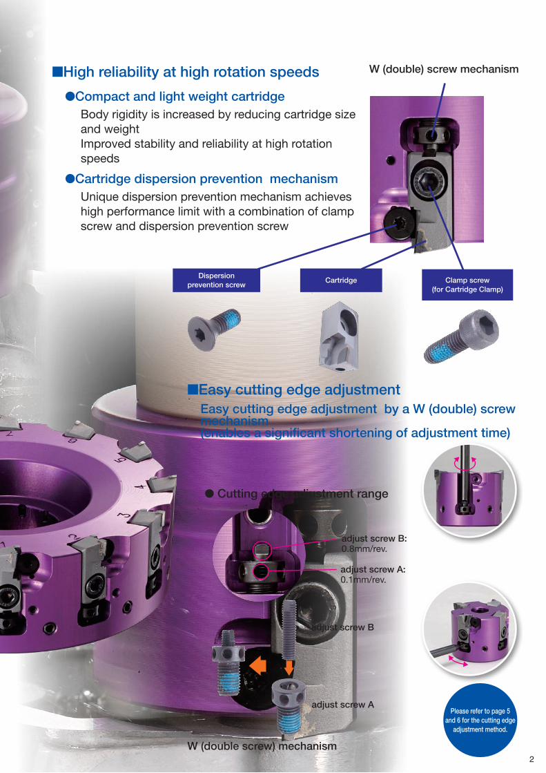
Clamp screw (for Cartridge Clamp)
CartridgeDispersion
prevention screw
adjust screw B
adjust screw A
● Cutting edge adjustment range
adjust screw B:0.8mm/rev.
adjust screw A:0.1mm/rev.
W (double) screw mechanism
■Easy cutting edge adjustmentEasy cutting edge adjustment by a W (double) screw mechanism(enables a significant shortening of adjustment time)
■High reliability at high rotation speeds
●Compact and light weight cartridgeBody rigidity is increased by reducing cartridge size and weightImproved stability and reliability at high rotation speeds
●Cartridge dispersion prevention mechanismUnique dispersion prevention mechanism achieves high performance limit with a combination of clamp screw and dispersion prevention screw
Please refer to page 5 and 6 for the cutting edge
adjustment method.
W (double screw) mechanism2
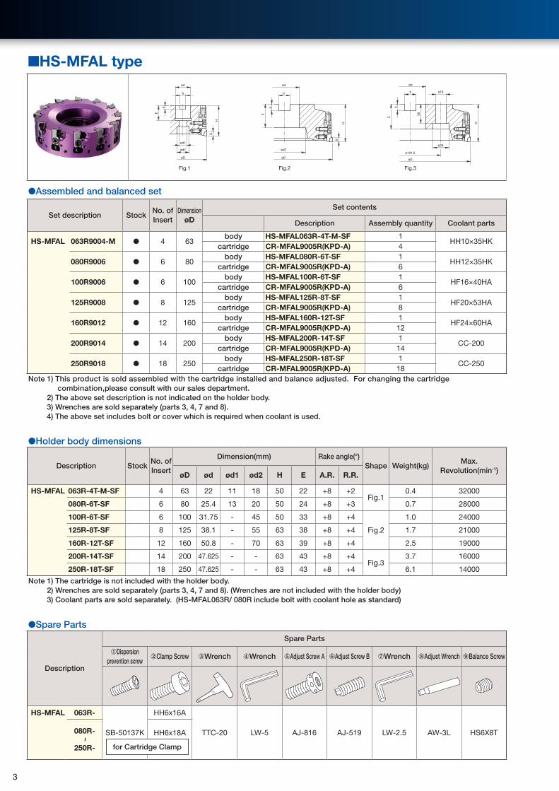
■HS-MFAL type
Fig.1 Fig.2 Fig.3
ød
ød1
ød2
øD
ød2
øD
b
ød
b
ød
ø18
ø26
øD
ø101.6
b
E
H
S
H
S
a
E
a
E
26
H
a
●Assembled and balanced set
Set description StockNo. of Insert
DimensionøD
Set contents
Description Assembly quantity Coolant parts
HS-MFAL 063R9004-M ● 4 63body HS-MFAL063R-4T-M-SF 1
HH10×35HKcartridge CR-MFAL9005R(KPD-A) 4
080R9006 ● 6 80body HS-MFAL080R-6T-SF 1
HH12×35HKcartridge CR-MFAL9005R(KPD-A) 6
100R9006 ● 6 100body HS-MFAL100R-6T-SF 1
HF16×40HAcartridge CR-MFAL9005R(KPD-A) 6
125R9008 ● 8 125body HS-MFAL125R-8T-SF 1
HF20×53HAcartridge CR-MFAL9005R(KPD-A) 8
160R9012 ● 12 160body HS-MFAL160R-12T-SF 1
HF24×60HAcartridge CR-MFAL9005R(KPD-A) 12
200R9014 ● 14 200body HS-MFAL200R-14T-SF 1
CC-200cartridge CR-MFAL9005R(KPD-A) 14
250R9018 ● 18 250body HS-MFAL250R-18T-SF 1
CC-250cartridge CR-MFAL9005R(KPD-A) 18
Note 1) This product is sold assembled with the cartridge installed and balance adjusted. For changing the cartridge combination,please consult with our sales department.
2) The above set description is not indicated on the holder body.3) Wrenches are sold separately (parts 3, 4, 7 and 8).4) The above set includes bolt or cover which is required when coolant is used.
●Holder body dimensions
Description StockNo. of Insert
Dimension(mm) Rake angle(°)Shape Weight(kg)
Max.Revolution(min-1)
øD ød ød1 ød2 H E A.R. R.R.
HS-MFAL 063R-4T-M-SF 4 63 22 11 18 50 22 +8 +2Fig.1
0.4 32000
080R-6T-SF 6 80 25.4 13 20 50 24 +8 +3 0.7 28000
100R-6T-SF 6 100 31.75 - 45 50 33 +8 +4
Fig.2
1.0 24000
125R-8T-SF 8 125 38.1 - 55 63 38 +8 +4 1.7 21000
160R-12T-SF 12 160 50.8 - 70 63 39 +8 +4 2.5 19000
200R-14T-SF 14 200 47.625 - - 63 43 +8 +4Fig.3
3.7 16000
250R-18T-SF 18 250 47.625 - - 63 43 +8 +4 6.1 14000
Note 1) The cartridge is not included with the holder body.2) Wrenches are sold separately (parts 3, 4, 7 and 8). (Wrenches are not included with the holder body)3) Coolant parts are sold separately. (HS-MFAL063R/ 080R include bolt with coolant hole as standard)
●Spare Parts
Description
Spare Parts
①Dispersion prevention screw
②Clamp Screw ③Wrench ④Wrench ⑤Adjust Screw A ⑥Adjust Screw B ⑦Wrench ⑧Adjust Wrench ⑨Balance Screw
HS-MFAL 063R-
SB-50137K
HH6x16A
TTC-20 LW-5 AJ-816 AJ-519 LW-2.5 AW-3L HS6X8T080R-
~
250R-
HH6x18A
for Cartridge Clamp
3
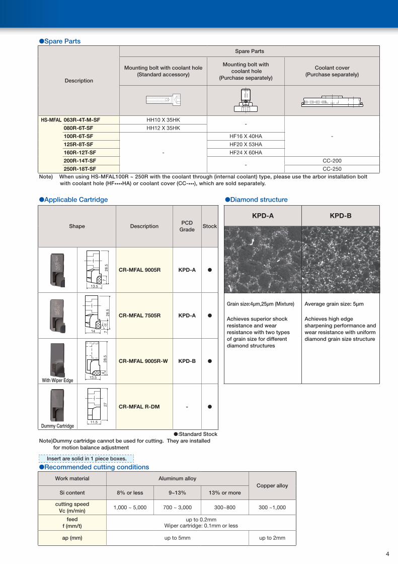
●Spare Parts
Description
Spare Parts
Mounting bolt with coolant hole(Standard accessory)
Mounting bolt with coolant hole
(Purchase separately)
Coolant cover (Purchase separately)
HS-MFAL 063R-4T-M-SF HH10 X 35HK-
-
080R-6T-SF HH12 X 35HK
100R-6T-SF
-
HF16 X 40HA
125R-8T-SF HF20 X 53HA
160R-12T-SF HF24 X 60HA
200R-14T-SF-
CC-200
250R-18T-SF CC-250Note) When using HS-MFAL100R ~ 250R with the coolant through (internal coolant) type, please use the arbor installation bolt
with coolant hole (HF••••HA) or coolant cover (CC-•••), which are sold separately.
●Applicable Cartridge ●Diamond structure
Shape DescriptionPCD
GradeStock
KPD-A KPD-B
7
13.5
28.5
CR-MFAL 9005R KPD-A ●
714
75°
28.5
CR-MFAL 7505R KPD-A ●
Grain size:4μm,25μm (Mixture)
Achieves superior shock resistance and wear resistance with two types of grain size for different diamond structures
Average grain size: 5μm
Achieves high edge sharpening performance and wear resistance with uniform diamond grain size structure
With Wiper Edge
4
13.5
28.5
CR-MFAL 9005R-W KPD-B ●
Dummy Cartridge11.5
27 CR-MFAL R-DM - ●
●:Standard StockNote)Dummy cartridge cannot be used for cutting. They are installed
for motion balance adjustment
Insert are solid in 1 piece boxes.
●Recommended cutting conditions
Work material Aluminum alloyCopper alloy
Si content 8% or less 9~13% 13% or more
cutting speedVc (m/min)
1,000 ~ 5,000 700 ~ 3,000 300~800 300 ~1,000
feedf (mm/t)
up to 0.2mmWiper cartridge: 0.1mm or less
ap (mm) up to 5mm up to 2mm
4
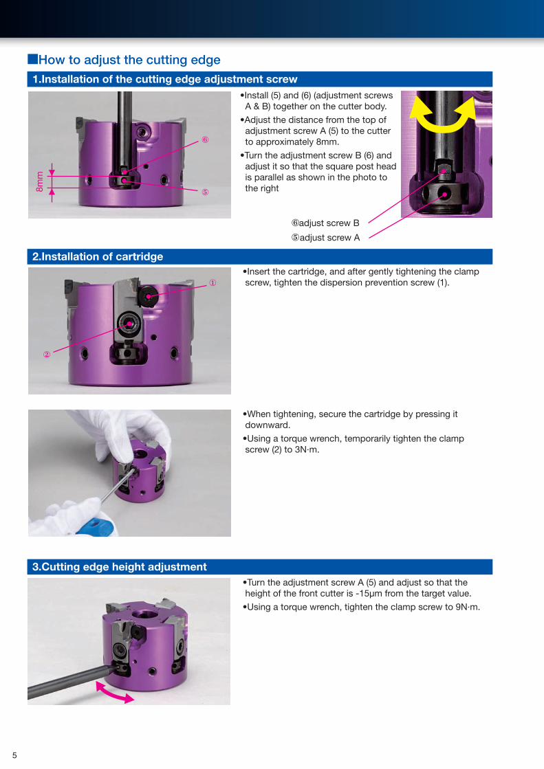
■How to adjust the cutting edge1.Installation of the cutting edge adjustment screw
•Install (5) and (6) (adjustment screws A & B) together on the cutter body.
•Adjust the distance from the top of adjustment screw A (5) to the cutter to approximately 8mm.
•Turn the adjustment screw B (6) and adjust it so that the square post head is parallel as shown in the photo to the right
2.Installation of cartridge•Insert the cartridge, and after gently tightening the clamp screw, tighten the dispersion prevention screw (1).
•When tightening, secure the cartridge by pressing it downward.
•Using a torque wrench, temporarily tighten the clamp screw (2) to 3N·m.
3.Cutting edge height adjustment•Turn the adjustment screw A (5) and adjust so that the height of the front cutter is -15μm from the target value.
•Using a torque wrench, tighten the clamp screw to 9N·m.
8mm
②
①
⑥
⑤
⑥adjust screw B
⑤adjust screw A
5
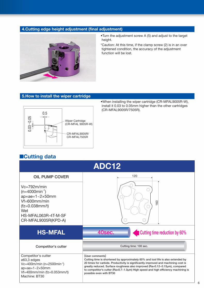
4.Cutting edge height adjustment (final adjustment)
•Turn the adjustment screw A (5) and adjust to the target height.
*Caution: At this time, if the clamp screw (2) is in an over tightened condition, the accuracy of the adjustment function will be lost.
5.How to install the wiper cartridge
0.03
˜ 0.
05
0.5
Wiper Cartridge(CR-MFAL 9005R-W)
CR-MFAL9005R/CR-MFAL7505R
•When installing the wiper cartridge (CR-MFAL9005R-W), install it 0.03 to 0.05mm higher than the other cartridges (CR-MFAL9005R/7505R).
■Cutting data
ADC12OIL PUMP COVER 120
160
Vc=792m/min(n=4000min-1)ap×ae=1~2×50mmVf=600mm/min(fz=0.038mm/t)WetHS-MFAL063R-4T-M-SFCR-MFAL9005R(KPD-A)
HS-MFAL
Competitor's cutter
Competitor's cutterø63,3 edgesVc=400m/min (n=2500min-1)ap×ae=1~2×50mmVf=400mm/min (fz=0.053mm/t)Machine: BT30
(User comments)Cutting time is shortened by approximately 60% and tool life is also extended by 20 times for carbide. Productivity is significantly improved and machining cost is greatly reduced. Surface roughness also improved (Ra=0.12~0.15μm), compared to competitor's cutter (Ra=0.7~1.0μm) High speed and high efficiency machining is possible even with BT30
40sec. Cutting time reduction by 60%
Cutting time: 100 sec.
6
Danger
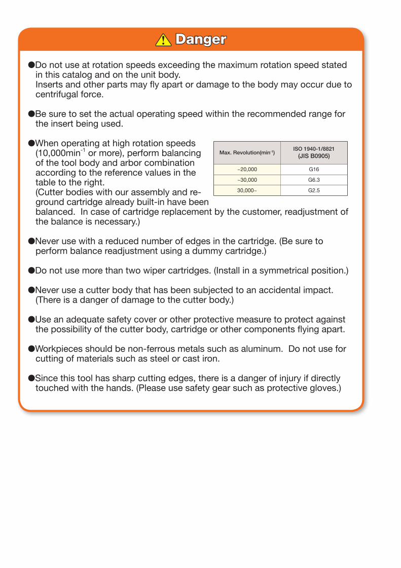
●Do not use at rotation speeds exceeding the maximum rotation speed stated in this catalog and on the unit body.Inserts and other parts may fly apart or damage to the body may occur due to centrifugal force.
●Be sure to set the actual operating speed within the recommended range for the insert being used.
●When operating at high rotation speeds (10,000min-1 or more), perform balancing of the tool body and arbor combination according to the reference values in the table to the right.(Cutter bodies with our assembly and re-ground cartridge already built-in have been balanced. In case of cartridge replacement by the customer, readjustment of the balance is necessary.)
●Never use with a reduced number of edges in the cartridge. (Be sure to perform balance readjustment using a dummy cartridge.)
●Do not use more than two wiper cartridges. (Install in a symmetrical position.)
●Never use a cutter body that has been subjected to an accidental impact. (There is a danger of damage to the cutter body.)
●Use an adequate safety cover or other protective measure to protect against the possibility of the cutter body, cartridge or other components flying apart.
●Workpieces should be non-ferrous metals such as aluminum. Do not use for cutting of materials such as steel or cast iron.
●Since this tool has sharp cutting edges, there is a danger of injury if directly touched with the hands. (Please use safety gear such as protective gloves.)
Max. Revolution(min-1)ISO 1940-1/8821
(JIS B0905)
~20,000 G16
~30,000 G6.3
30,000~ G2.5


![High-performance milling cutter NX-NVD - FRAISA SA milling cutter NX-NVD [ 2 ] The NX-NVD high-performance milling cutter with patented double groove ... 20 4 120 0.110 30.0 8.0 1910](https://img.pdfslide.us/doc/110x75/5aab05447f8b9aa06a8b6ee0/high-performance-milling-cutter-nx-nvd-fraisa-sa-milling-cutter-nx-nvd-2-the.jpg)