Embed Size (px)
Citation preview

High Speed Integrated Circuit Design
Faculty of Electrical Engineering and Information Technology, Chair for Circuit Design and Network Theory
Frank Ellinger
Chair for Circuit Design and Network Theory
Chair for Circuit Design and Network Theory, F. Ellinger
1. Adaptive antenna combining IC systems
2. Smart power amplifier IC systems
3. Local positioning RFICs and systems
4. High speed 60 GHz WLAN
Outline
4. High speed 60 GHz WLAN
5. High speed optical ICs
6. Beyond Moore nano-electronic circuit design
7. Some facts
8. Conclusions

Chair for Circuit Design and Network Theory, F. Ellinger
Pros
Only 1 IF/BB path
⇒ small size, power
consumption and costs
Easy system extension
Interferer
cancelled prior to ADC
1. Adaptive Antenna Combining in RF
cancelled prior to ADC
⇒ Relaxed specs for ADC
Challenges
Precise, compact, low-cost analogue
phase & gain control ICs
Avoid complex recursive adjustment:
⇒ Phase control with min. impact on gain
⇒ Gain control with min. impact on phase
(focus of this talk)

Chair for Circuit Design and Network Theory, F. Ellinger
• EU funded project MIMAX
• Coordinated by our chair
• 802.11a (C-band)
Example for Architecture

Chair for Circuit Design and Network Theory, F. Ellinger
Example for a RX SoC Implementation
• 4 x adaptive signal branches from RF down to baseband interface
• Including digital circuits for amplitude and phase control
• Low cost 250nm
IHP CMOS
• PDC ≈ 3.3V, 130mA
2.8 ×
2.5
mm2
Rohde Rohde
& Schwarz
EEEfCom
Innovation
Award 2009

Chair for Circuit Design and Network Theory, F. Ellinger
2. Class-F CMOS Power Amplifier for WPAN/LAN
9ΩMatching,Bias
Input
VddVgs
Output Matching,Filter
In
10pF
Out
180fF
54pH942pH
3.4pF534pH
10pF
4.34pF
L2
4.9pF
774pHL1
Ref. Tech. f VDD S21 P1dB Eff. @ P1dB
This work 0.18 CMOS 5.6GHz 1.9V 10dB 18.4dBm 50%
Biondi, RFIC 03
BiCMOS 5.2GHz 2.7V 13dB 18.2dBm 50%
1.66m
In180fF
723pH542pH
534pH
L3
J. Carls, F. Ellinger, U. Jörges and Marko Krcmar, “Highly Efficient 5 GHz - 6 GHz Class-F Power Amplifier for Low Supply Voltages in 180 nm CMOS”, submitted in 2008 to Microwave Wireless Component Letters
Chair for Circuit Design and Network Theory, F. Ellinger
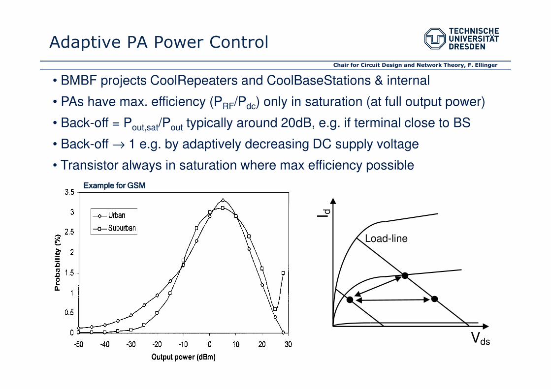
• BMBF projects CoolRepeaters and CoolBaseStations & internal
• PAs have max. efficiency (PRF/Pdc) only in saturation (at full output power)
• Back-off = Pout,sat/Pout typically around 20dB, e.g. if terminal close to BS
• Back-off → 1 e.g. by adaptively decreasing DC supply voltage
• Transistor always in saturation where max efficiency possible
Adaptive PA Power Control
Example for GSMExample for GSMExample for GSMExample for GSM
Vds I d
Load-line

Chair for Circuit Design and Network Theory, F. Ellinger
Envelope tracking
• Power known in baseband (BB)
• Slow dynamics due to delays between BB ⇔ PA
• Moderate efficiency improvement possible
• Demonstrated for GSM
DC
t
Control Methods
Envelope following
• Supply voltage directly follows envelope
• Higher efficiency improvement possible
• Very fast control dynamics required
• Full control in analogue to maximize speed & BW
• No baseband connection required
DC
t

Chair for Circuit Design and Network Theory, F. Ellinger
• Efficiency improvement depends on required dynamics/BW of standard
• CMOS losses considered
• SOA: dc generation by buck converter & saw tooth generator
• Slow/lossy since periodic control over full duty cycle (several periods)
Control Algorithms
Envelope Following
3
2.5
ciency enhancement
BW
0.2kHz
5MHz
20MHzDC-DC
Converter
Vg Vd
PA
Envelope detector
Coupler
In Out
F. Haßler, F. Ellinger and J. Carls (CCN), “Analysis of Buck-Converters for Efficiency Enhancements in
Power Amplifiers for Wireless Communication”, best student paper award, IEEE IMOC 2007
2.5
2
1.5
1
0.5
Efficiency enhancement
Typical back-off
20MHz

Chair for Circuit Design and Network Theory, F. Ellinger
Integrated Control System
• No limiting conventional buck c. & saw tooth
• Fast since non-periodic, goal-oriented control
• Integrated in 0.18 µm CMOS (7WL)
• Excl. PA and LC LP
• VDC and IDC up to 3.3 V and 280 mA
• Efficiency enhancement of UMTSEfficiency enhancement of UMTSEfficiency enhancement of UMTSEfficiency enhancement of UMTS class-AB PA
systems with factor > 2> 2> 2> 2 over average back-off
F. Haßler (CCN), internal report, publication pending
Single chip, 0.16 mm2
Chair for Circuit Design and Network Theory, F. Ellinger
Ou
tdo
or
Ou
tdo
or
glo
bal
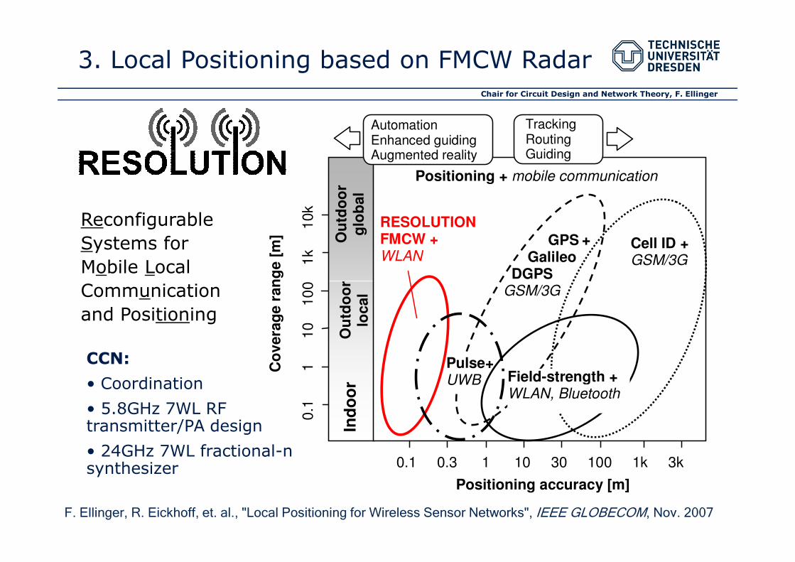
RESOLUTION FMCW + WLAN
GPS Galileo DGPS
Cell ID + GSM/3G
Positioning + mobile communication
0.1
1
10
10
0
1k
1
0k
Co
vera
ge
ran
ge [
m]
Tracking Routing Guiding
Automation Enhanced guiding Augmented reality
Reconfigurable
Systems for
Mobile Local
Communication
+
3. Local Positioning based on FMCW Radar
Ind
oo
r O
utd
oo
r lo
cal
DGPS GSM/3G
0.1 0.3 1 10 30 100 1k 3k
0.1
1
10
10
0
1k
1
0k
Positioning accuracy [m]
Co
vera
ge
ran
ge [
m]
Field-strength + WLAN, Bluetooth
Pulse+ UWB
Communication
and Positioning
CCN:
• Coordination
• 5.8GHz 7WL RF transmitter/PA design
• 24GHz 7WL fractional-n synthesizer
F. Ellinger, R. Eickhoff, et. al., "Local Positioning for Wireless Sensor Networks", IEEE GLOBECOM, Nov. 2007
Chair for Circuit Design and Network Theory, F. Ellinger
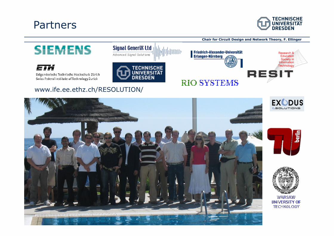
www.ife.ee.ethz.ch/RESOLUTION/
Partners
Chair for Circuit Design and Network Theory, F. Ellinger
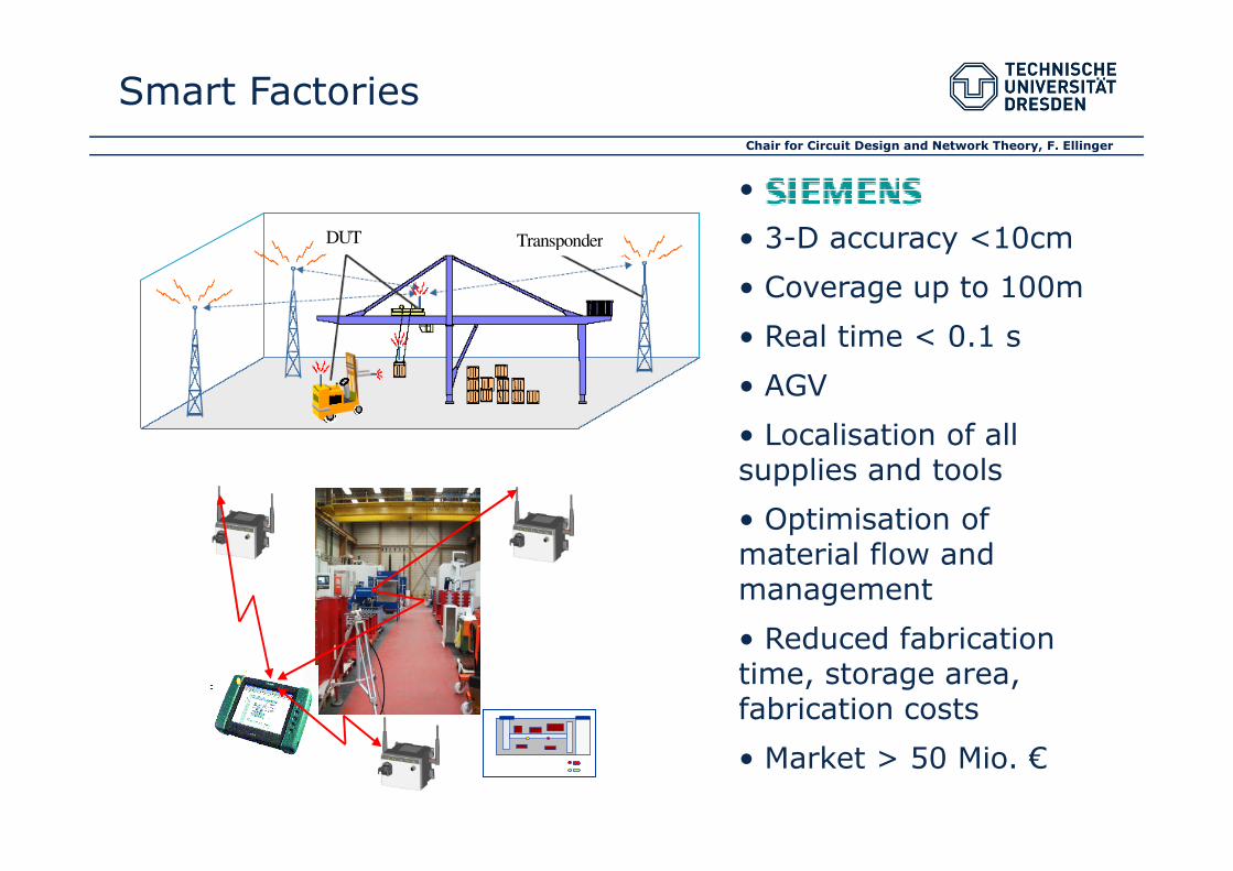
Smart Factories
DUT Transponder
•
• 3-D accuracy <10cm
• Coverage up to 100m
• Real time < 0.1 s
• AGV
• Localisation of all • Localisation of all supplies and tools
• Optimisation of material flow and management
• Reduced fabrication time, storage area, fabrication costs
• Market > 50 Mio. €
Chair for Circuit Design and Network Theory, F. Ellinger
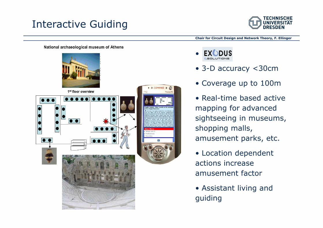
•
• 3-D accuracy <30cm
• Coverage up to 100m
• Real-time based active
mapping for advanced
sightseeing in museums,
Interactive Guiding
sightseeing in museums,
shopping malls,
amusement parks, etc.
• Location dependent
actions increase
amusement factor
• Assistant living and
guiding
Chair for Circuit Design and Network Theory, F. Ellinger
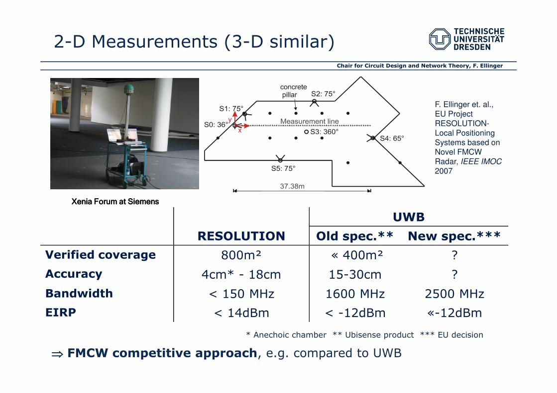
2-D Measurements (3-D similar)
F. Ellinger et. al.,
EU Project
RESOLUTION-
Local Positioning
Systems based on
Novel FMCW
Radar, IEEE IMOC
2007
RESOLUTION
UWB
Old spec.** New spec.***
Verified coverage 800m² « 400m² ?
Accuracy 4cm* - 18cm 15-30cm ?
Bandwidth < 150 MHz 1600 MHz 2500 MHz
EIRP < 14dBm < -12dBm «-12dBm
⇒⇒⇒⇒ FMCW competitive approach, e.g. compared to UWB
* Anechoic chamber ** Ubisense product *** EU decision
Xenia Forum at SiemensXenia Forum at SiemensXenia Forum at SiemensXenia Forum at Siemens
Chair for Circuit Design and Network Theory, F. Ellinger
10G
1G
100M
10M10x Cellular / WAN
LAN
Short linksShort links
USB2.0
10G Ethernet
802.11n
802.11a
UWB
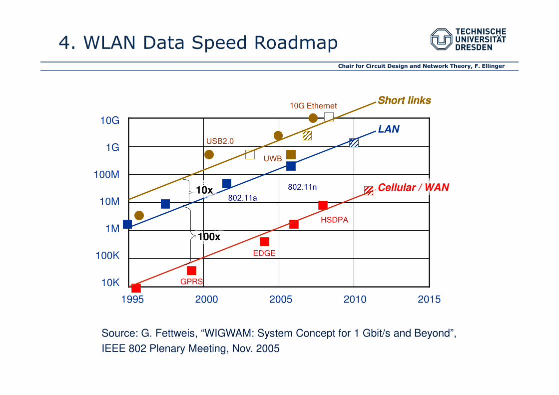
4. WLAN Data Speed Roadmap
10M
1M
100K
10K
1995 2000 2005 2010 2015
100x
HSDPA
EDGE
GPRS
802.11a
Source: G. Fettweis, “WIGWAM: System Concept for 1 Gbit/s and Beyond”,
IEEE 802 Plenary Meeting, Nov. 2005

Chair for Circuit Design and Network Theory, F. Ellinger
60 GHz SiGe Power Amplifier
Highest PAE of 22% in Silicon
M. Hellfeld and F. Ellinger, “Universal Millimeter Wave Power Amplifier Design Method
verified at 60 GHz in SiGe”, submitted to IET Journal on Circuits, Devices and Systems

Chair for Circuit Design and Network Theory, F. Ellinger
60 GHz SiGe VGLNA
OVERVIEW OF RECENT V- AND W-BAND LNA DESIGNS
This work [1] [2] [3] [4] [5]
Process fT /
active devices
190 GHz /
SiGe-HBTs
180 GHz /
SiGe-HBTs
190 GHz /
SiGe-HBTs
200 GHz /
SiGe-HBTs
200 GHz /
SiGe-HBTs
200 GHz /
SiGe-HBTs
Peak gain
frequency f0
63.5 GHz 60 GHz 79 GHz 59 GHz 61.5 GHz 79 GHz
|S21| at f0 21.4 dB 18 dB 16 dB 14.5 dB 14.7 dB 21.7 dB
NF at f0 6.0 dB 6.8 dB n/a 5 dB 4.5 dB 10.2 dB
DC power 7.3 mW 66 mW 90 mW 8.1 mW 10.8 mW 105 mW
Remarks variable gain differential differential
Highest gain vs dc power in silicon
S. Hauptmann, F. Ellinger, et. al, “V-Band Variable Gain Amplifier
applying Efficient Design Methodology with Scalable Transmission
Lines”, IET Journal on Circuits, Devices and Systems, 2010
Chair for Circuit Design and Network Theory, F. Ellinger
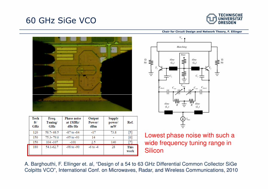
60 GHz SiGe VCO
Matching
bias
Ω
50
Ω
50
C1
tline
(Lb)
tline
(Lb)
T1 T2
C1
CblockCblock CvarCvar
Vtune
Vcc
tline
(Le)
tline
(Le)
Ibias
RR
Lowest phase noise with such a wide frequency tuning range in Silicon
A. Barghouthi, F. Ellinger et. al, “Design of a 54 to 63 GHz Differential Common Collector SiGe
Colpitts VCO”, International Conf. on Microwaves, Radar, and Wireless Communications, 2010

Chair for Circuit Design and Network Theory, F. Ellinger
5. High Speed ICs for Optical Communication
LWL
MU
X
N:1 MOD
Laserdiode
Transmitter
Receiver
Photodiode
TIA LA CDR
DE
MU
X
1:N
LWL
MU
X
N:1 MOD
Laserdiode
Transmitter
Receiver
Photodiode
TIA LA CDR
DE
MU
X
1:N
Chair for Circuit Design and Network Theory, F. Ellinger
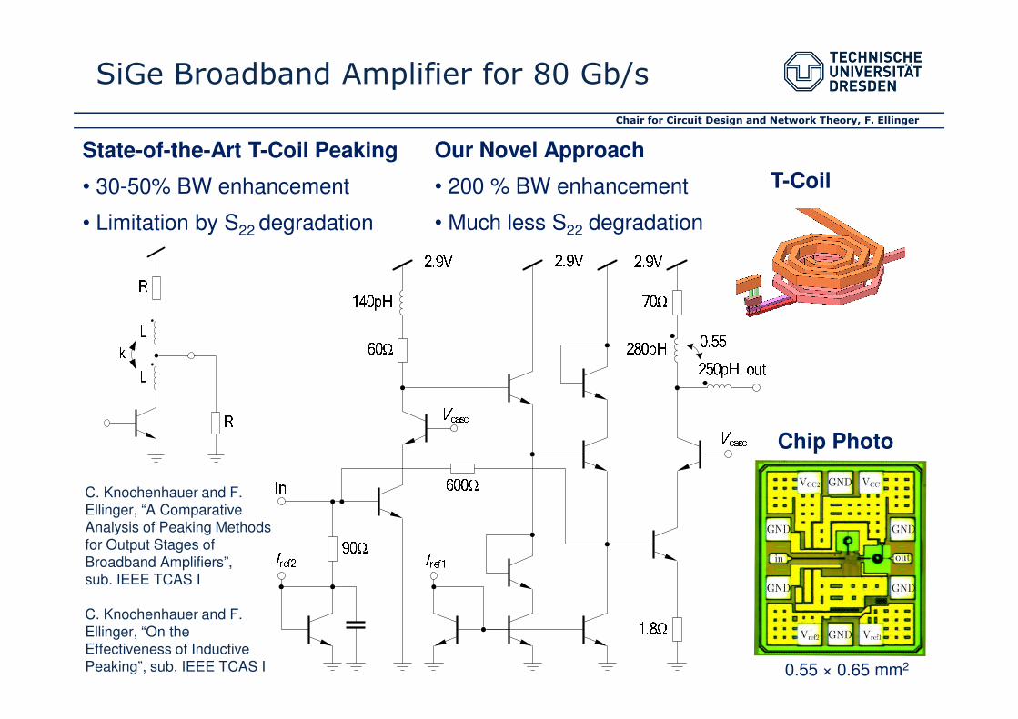
SiGe Broadband Amplifier for 80 Gb/s
State-of-the-Art T-Coil Peaking
• 30-50% BW enhancement
• Limitation by S22 degradation
Our Novel Approach
• 200 % BW enhancement
• Much less S22 degradation
T-Coil
Chip Photo
0.55 × 0.65 mm2
C. Knochenhauer and F.
Ellinger, “A Comparative
Analysis of Peaking Methods
for Output Stages of
Broadband Amplifiers”,
sub. IEEE TCAS I
C. Knochenhauer and F.
Ellinger, “On the
Effectiveness of Inductive
Peaking”, sub. IEEE TCAS I

Chair for Circuit Design and Network Theory, F. Ellinger
SiGe Broadband Amplifier for 80 Gb/s
Transmission Gain 50 Ω Output Matching Measurement
at 55 G/s
• highest rate of
our test set
• Simulation up
to 80 GB/s
Comparison with State of the Art SiGe Amps

Chair for Circuit Design and Network Theory, F. Ellinger
40 Gb/s SiGe TIA
S. Hauptmann, D. Schoeniger, R. Eickhoff, F. Ellinger, and C. Scheytt,
“A 40 Gbit/s Trans-impedance Amplifier in 0.25 µm SiGe Technology
with ultra low power consumption”, IEEE MIKON 2008
Reference Tech ZT/ΩΩΩΩ B/GHz In,in pA/√Hz P/mW
Jin, JSSC 08 CMOS 350 31 <55.7 60
Weiner, JSSC 03 BiCMOS 140 50.0 <30 200
This work BiCMOS 4500 30 <25 32
Chair for Circuit Design and Network Theory, F. Ellinger
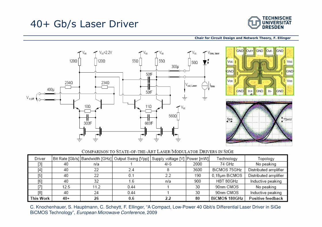
40+ Gb/s Laser Driver
C. Knochenhauer, S. Hauptmann, C. Scheytt, F. Ellinger, “A Compact, Low-Power 40 Gbit/s Differential Laser Driver in SiGe
BiCMOS Technology”, European Microwave Conference, 2009

Chair for Circuit Design and Network Theory, F. Ellinger
40 Gb/s Modulator Driver with
Breakdown Voltage Doubler
6Vpp (differential)
C. Knochenhauer, C. Scheytt, F. Ellinger, “A Compact, Low-Power 40 Gbit/s Modulator Driver with 6 V Output Swing in SiGe
BiCMOS, to be submitted to IEEE JSSC
Chair for Circuit Design and Network Theory, F. Ellinger
7. Beyond Moore Circuit Design
Scaling is already dead but nobody noticed it had stopped
breathing and its lips had turned blue
B. Meyerson, IBM CTO, 2003
⇒ Circuit R&D on “Beyond Moore” technologies started, e.g.:
• CNT (simulation of CNT RF amplifier)
• Organic/printed (simulation of organic audio amplifier)
• Silicon Nano Wire (project proposal)

Chair for Circuit Design and Network Theory, F. Ellinger
Core competence CCN: High-speed and low power
consuming analogue/RF ICs and systems
Complete RFIC frontends and interfaces
Rigorously optimized circuit blocks: PAs, LNAs, mixers, VCOs,
synthesizers, DC/DC converters, TIAs, drivers, (ADC/DAC), etc.
Specific research areas:
8. Conclusions
Specific research areas:
- Adaptive antenna combining, RF MIMO and beamforming
- Smart power amplifiers with high efficiency
- Local positioning sensors based on FMCW radar
- RFIC development 100 MHz - 220 GHz, up to 10 Gb/s
- High speed ICs for optical data communication up to 80 Gb/s
- Beyond Moore nano electronic circuit design (started)
Chair for Circuit Design and Network Theory, F. Ellinger
10-Nov-10, 28/30

Chair for Circuit Design and Network Theory, F. Ellinger
Dresden University of Technology
thanks you for your attention!
Dresden