Embed Size (px)
Citation preview
High Speed FusesFor the Protection of Power Semiconductors
February 1998
British Style BS 88
67For complete specification data, visit our Web site at www.bussmann.comor call Bussmann Information Fax ~ 314.527.1450
Introduction
Bussmann®
General Information
Designed and tested to:
• BS 88: Part 4• IEC 269: Part 4• U.L. Recognized
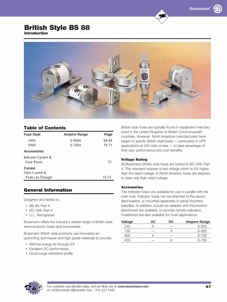
Bussmann offers the industry’s widest range of British stylesemiconductor fuses and accessories.
Bussmann British style products use innovative arcquenching techniques and high grade materials to provide:
• Minimal energy let-through (I2t)• Excellent DC performance• Good surge withstand profile
British style fuses are typically found in equipment manufac-tured in the United Kingdom or British Commonwealthcountries. However, North American manufacturers havebegun to specify British style fuses — particularly in UPSapplications at 240 volts or less — to take advantage oftheir size, performance and cost benefits.
Voltage Rating
All Bussmann British style fuses are tested to IEC 269: Part4. This standard requires a test voltage which is 5% higherthan the rated voltage. In North America, fuses are requiredto clear only their rated voltage.
Accessories
Trip-indicator fuses are available for use in parallel with themain fuse. Indicator fuses can be attached to the associ-ated fuselink, or mounted separately in panel-mountedfuseclips. In addition, a push-on adaptor and microswitchattachment are available, to provide remote indication.Fuseblocks are also available for most applications.
Voltage AC DC Ampere Range240 X — 6-900150 — X 6-900690 X — 6-700450 — X 6-700
Table of Contents
Fuse Style Ampere Range Page
240V 6-900A 68-69690V 6-700A 70-71
Accessories
Indicator System &Fuse Bases 72
CurvesTime-Current & Peak Let-Through 73-77
Bussmann®
British Style BS 88
240V 6-900A
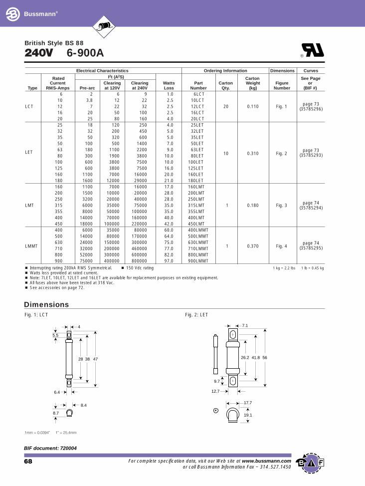
1 kg = 2.2 lbs 1 lb = 0.45 kg
Electrical Characteristics Ordering
Rated I2t (A2S)Current Clearing Clearing Watts Part C
Type RMS-Amps Pre-arc at 120V at 240V Loss Number6 2 6 9 1.0 6LCT
10 3.8 12 22 2.5 10LCTLCT 12 7 22 32 2.5 12LCT
16 20 50 100 2.5 16LCT20 25 80 160 4.0 20LCT25 18 120 250 4.0 25LET32 32 200 450 5.0 32LET35 50 320 600 5.0 35LET50 100 500 1400 7.0 50LET
LET 63 180 1100 2200 9.0 63LET80 300 1900 3800 10.0 80LET
100 600 3800 7500 10.0 100LET125 600 3800 7500 16.0 125LET160 1100 7000 16000 20.0 160LET180 1600 12000 29000 21.0 180LET160 1100 7000 16000 17.0 160LMT200 1500 10000 20000 28.0 200LMT250 3200 20000 40000 28.0 250LMT
LMT 315 6000 35000 75000 35.0 315LMT355 8000 50000 100000 35.0 355LMT400 14000 70000 160000 40.0 400LMT450 18000 100000 220000 42.0 450LMT400 6000 35000 80000 60.0 400LMMT500 14000 80000 170000 64.0 500LMMT630 24000 150000 300000 75.0 630LMMT
LMMT 710 32000 200000 460000 77.0 710LMMT800 52000 300000 600000 82.0 800LMMT900 75000 400000 800000 97.0 900LMMT
n Interrupting rating 200kA RMS Symmetrical. n 150 Vdc ratingn Watts loss provided at rated current.n Note: 7LET, 10LET, 12LET and 16LET are available for replacement purposes on existing equipment.n All fuses above have been tested at 318 Vac.
68 For complete specificatio
BIF document: 720004
1mm = 0.0394∑ 1∑ = 25.4mm
®
Information Dimensions Curves
Carton See Pagearton Weight Figure orQty. (kg) Number (BIF #)
page 7320 0.110 Fig. 1 (35785296)
page 7310 0.310 Fig. 2 (35785293)
page 741 0.180 Fig. 3 (35785294)
page 741 0.370 Fig. 4 (35785295)
n See accessories on page 72.
Fig. 1: LCT
473828
6.4
8.4
8.7
4
5.5
Dimensions
5641.826.2
17.7
19.1
12.7
7.1
9.7
Fig. 2: LET
n data, visit our Web site at www.bussmann.comor call Bussmann Information Fax ~ 314.527.1450
Bussmann®
British Style BS 88
240V 6-900A
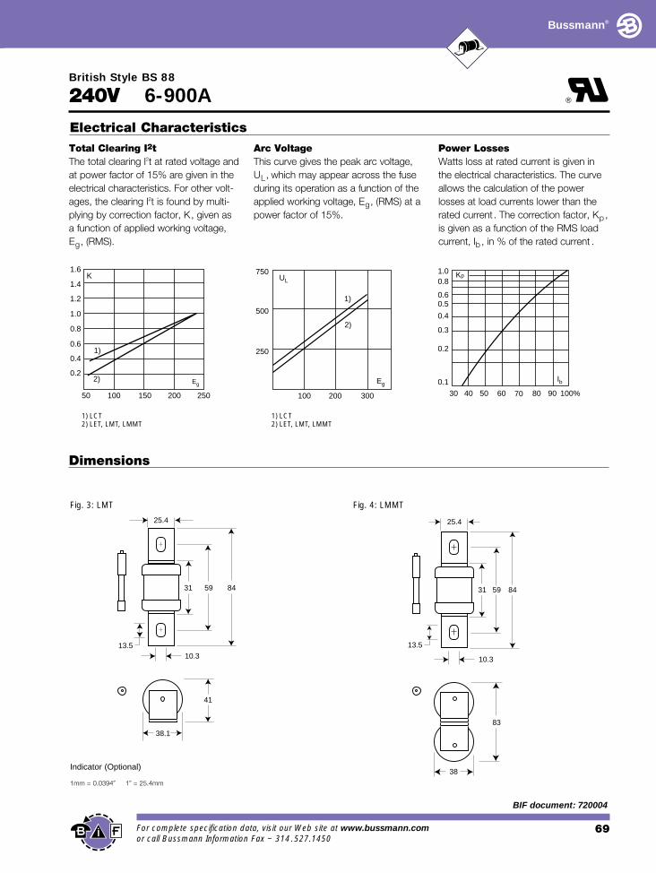
Total Clearing I2t
The total clearing I2t at rated voltage andat power factor of 15% are given in theelectrical characteristics. For other volt-ages, the clearing I2t is found by multi-plying by correction factor, K, given as a function of applied working voltage,Eg, (RMS).
Arc Voltage
This curve gives the peak arc voltage,UL, which may appear across the fuseduring its operation as a function of theapplied working voltage, Eg, (RMS) at apower factor of 15%.
Electrical Characteristics
0.2
0.4
0.6
0.8
1.0
1.2
1.4
1.6
10050 150 200 250
1)
2) Eg
K 750
500
250
100 200 300
1)
2)
Eg
UL
1) LCT 1) LCT
For complete specification daor call Bussmann Information
Dimensions
1mm = 0.0394∑ 1∑ = 25.4mm
2) LET, LMT, LMMT
®
Power Losses
Watts loss at rated current is given inthe electrical characteristics. The curveallows the calculation of the powerlosses at load currents lower than therated current. The correction factor, Kp ,is given as a function of the RMS loadcurrent, Ib , in % of the rated current .
Kp1.00.8
0.4
0.50.6
0.3
0.2
0.1
30 40 50 60 70 80 90 100%
Ib
2) LET, LMT, LMMT
845931
41
38.1
25.4
10.313.5
Fig. 3: LMT
Indicator (Optional)
ta, visit our Web site Fax ~ 314.527.1450
845931
83
38
25.4
13.5
10.3
Fig. 4: LMMT
69 at www.bussmann.com
BIF document: 720004
Bussmann®
British Style BS 88
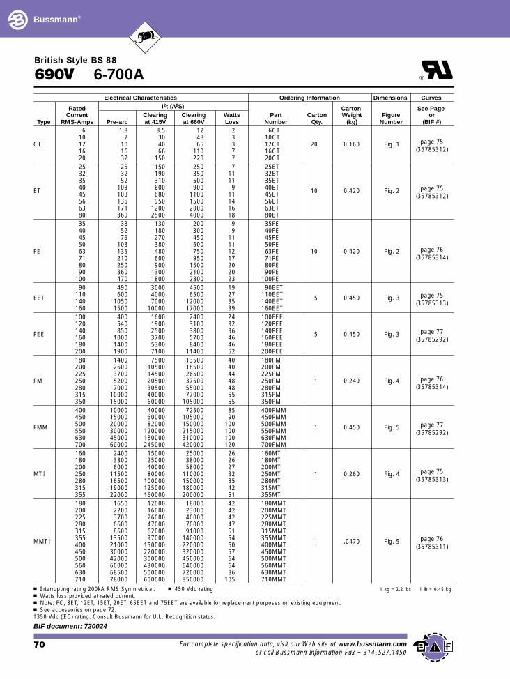
1 kg = 2.2 lbs 1 lb = 0.45 kg
690V 6-700AElectrical Characteristics
Rated I2t (A2S)Current Clearing Clearing Watts
Type RMS-Amps Pre-arc at 415V at 660V Loss6 1.8 8.5 12 2
10 7 30 48 3CT 12 10 40 65 3
16 16 66 110 720 32 150 220 725 25 150 250 732 32 190 350 1135 52 310 500 11
ET 40 103 600 900 945 103 680 1100 1156 135 950 1500 1463 171 1200 2000 1680 360 2500 4000 1835 33 130 200 940 52 180 300 945 76 270 450 1150 103 380 600 11
FE 63 135 480 750 1271 210 600 950 1780 250 900 1500 2090 360 1300 2100 20
100 470 1800 2800 2390 490 3000 4500 19
EET 110 600 4000 6500 27140 1050 7000 12000 35160 1500 10000 17000 39100 400 1600 2400 24120 540 1900 3100 32
FEE 140 850 2500 3800 36160 1000 3700 5700 46180 1400 5300 8400 46200 1900 7100 11400 52180 1400 7500 13500 40200 2600 10500 18500 40225 3700 14500 26500 44
FM 250 5200 20500 37500 48280 7000 30500 55000 48315 10000 40000 77000 55350 15000 60000 105000 55400 10000 40000 72500 85450 15000 60000 105000 90500 20000 82000 150000 100FMM 550 30000 120000 215000 100630 45000 180000 310000 100700 60000 245000 420000 120160 2400 15000 25000 26180 3800 25000 38000 26200 6000 40000 58000 27
MT† 250 11500 80000 110000 32280 16500 100000 150000 35315 19000 125000 180000 42355 22000 160000 200000 51180 1650 12000 18000 42200 2200 16000 23000 42225 3700 26000 40000 42280 6600 47000 70000 47315 8600 62000 91000 51
MMT† 355 13500 97000 140000 54400 21000 150000 220000 60450 30000 220000 320000 57500 42000 300000 450000 64560 60000 430000 640000 64630 68500 500000 720000 86710 78000 600000 850000 105
n Interrupting rating 200kA RMS Symmetrical. n 450 Vdc ratingn Watts loss provided at rated current.n Note: FC, 8ET, 12ET, 15ET, 20ET, 65EET and 75EET are available for replacemen See accessories on page 72.†350 Vdc (IEC) rating. Consult Bussmann for U.L. Recognition status.
70 For complete specificat
BIF document: 720024
®
Ordering Information Dimensions Curves
Carton See PagePart Carton Weight Figure or
Number Qty. (kg) Number (BIF #)6CT
10CTpage 7512CT 20 0.160 Fig. 1
16CT (35785312)20CT25ET32ET35ET40ET 10 0.420 Fig. 2 page 7545ET (35785312)56ET63ET80ET35FE40FE45FE50FE
page 7663FE 10 0.420 Fig. 271FE (35785314)80FE90FE
100FE90EET
110EET 5 0.450 Fig. 3 page 75140EET (35785313)160EET100FEE120FEE140FEE 5 0.450 Fig. 3 page 77160FEE (35785292)180FEE200FEE180FM200FM225FM
page 76250FM 1 0.240 Fig. 4280FM (35785314)315FM350FM400FMM450FMM500FMM 1 0.450 Fig. 5 page 77550FMM (35785292)630FMM700FMM160MT180MT200MT
page 75250MT 1 0.260 Fig. 4280MT (35785313)315MT355MT180MMT200MMT225MMT280MMT315MMT355MMT 1 .0470 Fig. 5 page 76400MMT (35785311)450MMT500MMT560MMT630MMT710MMT
nt purposes on existing equipment.
ion data, visit our Web site at www.bussmann.comor call Bussmann Information Fax ~ 314.527.1450
Bussmann®
British Style BS 88
690V 6-700A
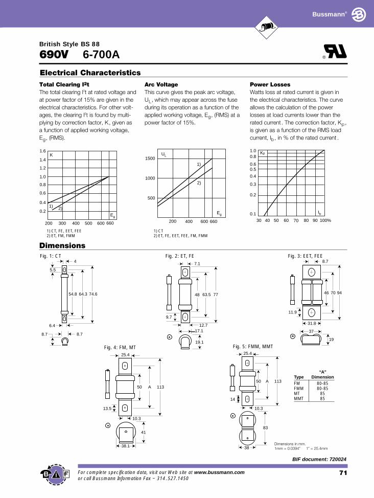
Total Clearing I2t
The total clearing I2t at rated voltage andat power factor of 15% are given in theelectrical characteristics. For other volt-ages, the clearing I2t is found by multi-plying by correction factor, K, given as a function of applied working voltage,Eg, (RMS).
Arc Voltage
This curve gives the peak arc voltage,UL, which may appear across the fuseduring its operation as a function of theapplied working voltage, Eg, (RMS) at apower factor of 15%.
Electrical Characteristics
200 300 400 500 600 660
0.2
0.4
0.6
0.8
1.0
1.2
1.4
1.6
1) 2)
Eg
K1500
1000
500
200 400 600 660
Eg
UL
1)
2)
1) CT, FE, EET, FEE 1) CT
For complete specification daor call Bussmann Information
2) ET, FM, FMM
®
Power Losses
Watts loss at rated current is given inthe electrical characteristics. The curveallows the calculation of the powerlosses at load currents lower than therated current. The correction factor, Kp ,is given as a function of the RMS loadcurrent, Ib , in % of the rated current .
Kp1.00.8
0.4
0.50.6
0.3
0.2
0.1
30 40 50 60 70 80 90 100%
Ib
2) ET, FE, EET, FEE, FM, FMM
Dimensions
7763.548
17.1
19.1
12.7
7.1
9.7
Fig. 2: ET, FE
74.664.354.8
6.4
8.78.7
4
5.5
Fig. 1: CT
ta, visit Fax ~ 3
947046
37
19
31.8
8.7
11.9
Fig. 3: EET, FEE
113A50
41
38.1
25.4
10.3
13.5
113A50
83
38
25.4
10.3
14
Fig. 4: FM, MT Fig. 5: FMM, MMT
Dimensions in mm.1mm = 0.0394∑ 1∑ = 25.4mm
“A”Type DimensionFM 80-85FMM 80-85MT 85MMT 85
71our Web site at www.bussmann.com14.527.1450
BIF document: 720024
Bussmann®
British Style BS 88 – Accessories
ases (Blocks)
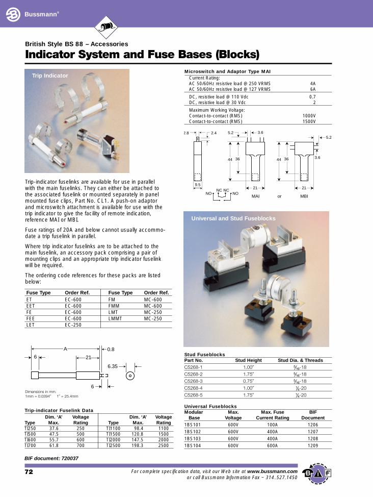
1BS104 600V 600A 1209
Indicator System and Fuse B
Trip-indicator fuselinks are available for use in parallel with the main fuselinks. They can either be attached to the associated fuselink or mounted separately in panelmounted fuse clips, Part No. CL1. A push-on adaptor and microswitch attachment is available for use with the trip indicator to give the facility of remote indication, reference MAI or MBI.
Fuse ratings of 20A and below cannot usually accommo-date a trip fuselink in parallel.
Where trip indicator fuselinks are to be attached to themain fuselink, an accessory pack comprising a pair ofmounting clips and an appropriate trip indicator fuselink will be required.
The ordering code references for these packs are listedbelow:
6 21
A 0.8
6.35
6
Fuse Type Order Ref. Fuse Type Order Ref.ET EC-600 FM MC-600EET EC-600 FMM MC-600FE EC-600 LMT MC-250FEE EC-600 LMMT MC-250LET EC-250
Trip-indicator Fuselink DataDim. ‘A’ Voltage Dim. ‘A’ Voltage
Type Max. Rating Type Max. RatingTI250 37.6 250 TI1100 98.4 1100TI500 47.5 500 TI1500 120.8 1500TI600 55.7 600 TI2000 147.5 2000TI700 61.8 700 TI2500 198.3 2500
Dimensions in mm.1mm = 0.0394∑ 1∑ = 25.4mm
Trip Indicator
72 For complete specificat
BIF document: 720037
2.8 2.4 3.65.2
5.2
21
3644 3.6
21
3644
9.5NC NC
NONO
Microswitch and Adaptor Type MAICurrent Rating:AC 50/60Hz resistive load @ 250 VRMS 4AAC 50/60Hz resistive load @ 127 VRMS 6A
DC, resistive load @ 110 Vdc 0.7DC, resistive load @ 30 Vdc 2
Maximum Working Voltage:Contact-to-contact (RMS) 1000VContact-to-contact (RMS) 1500V
Stud FuseblocksPart No. Stud Height Stud Dia. & ThreadsC5268-1 1.00∑ fiΩ¡§-18
C5268-2 1.75∑ fiΩ¡§-18
C5268-3 0.75∑ fiΩ¡§-18
C5268-4 1.00∑ ⁄Ω¢-20
C5268-5 1.75∑ ⁄Ω¢-20
Universal FuseblocksModular Max. Max. Fuse BIF
Base Voltage Current Rating Document1BS101 600V 100A 12061BS102 600V 400A 12071BS103 600V 400A 1208
Universal and Stud Fuseblocks
MAI or MBI
ion data, visit our Web site at www.bussmann.comor call Bussmann Information Fax ~ 314.527.1450
British Style BS 88
Bussmann®
Curves
Peak Let-Through Curve
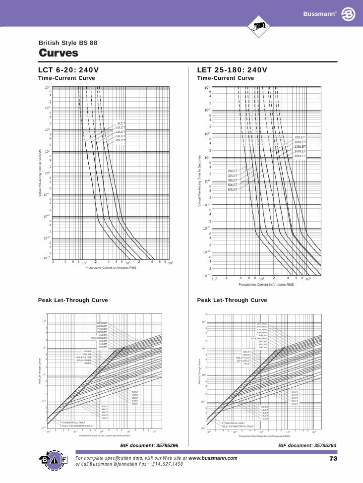
LCT 6-20: 240VTime-Current Curve
104
103
102
10–1
10–2
10–3
10–4
Prospective Current In Amperes RMS
Virt
ual P
re-A
rcin
g Ti
me
In S
econ
ds
2 4 6 8 101 22 4 6 8 2102 2 4 6 8 103
2
46
2
64
100
2
64
101
2
64
2
64
2
64
64
2
6
2
4
20LCT16LCT12LCT10LCT6LCT
Prospective Short-Circuit Current Symmetrical RMS
10–2 10–12 64 2 4 6100 2 4 6
101 2 4 6102
Pea
k Le
t-T
hrou
gh C
urre
nt
10–2
6
2
4
2
10–1
4
6
2
100
6
4
101
6
4
2
2
102
SYMMETRICAL FAULT
FULLY ASYMMETRICAL FAULT
20LCT16LCT12LCT10LCT 6LCT
25LET32LET35LET50LET63LET
80LET125 & 100LET
160LET & LMT200LMT180LET
250LMT315LMT355LMT
400 & 500LMMT450LMT
630LMMT710LMMT800LMMT900LMMT
For complete specification data, visit our Web site at wor call Bussmann Information Fax ~ 314.527.1450
BIF document: 35785296
Peak Let-Through Curve
LET 25-180: 240VTime-Current Curve
104
103
102
101 22 4 6 8 2102 2 4 6 8 103
2
46
2
64
100
2
64
101
2
64
2
64
2
64
64
2
6
2
4
Prospective Current In Amperes RMS
Virt
ual P
re-A
rcin
g Ti
me
In S
econ
ds
63LET50LET35LET32LET25LET
180LET160LET125LET100LET 80LET
10–4
10–3
10–2
10–1
Prospective Short-Circuit Current Symmetrical RMS
10–2 10–12 64 2 4 6100 2 4 6
101 2 4 6102
Pea
k Le
t-T
hrou
gh C
urre
nt
10–2
6
2
4
2
10–1
4
6
2
100
6
4
101
6
4
2
2
102
SYMMETRICAL FAULT
FULLY ASYMMETRICAL FAULT
20LCT16LCT12LCT10LCT 6LCT
25LET32LET35LET50LET63LET
80LET125 & 100LET
160LET & LMT200LMT180LET
250LMT315LMT355LMT
400 & 500LMMT450LMT
630LMMT710LMMT800LMMT900LMMT
73ww.bussmann.com
BIF document: 35785293
British Style BS 88
Bussmann®
Curves
10–4
10–3
10–1
102
102 22 4 6 8 2103 2 4 6 8 104
2
46
2
64
100
2
64
101
2
64
2
64
2
64
64
2
6
2
4
104
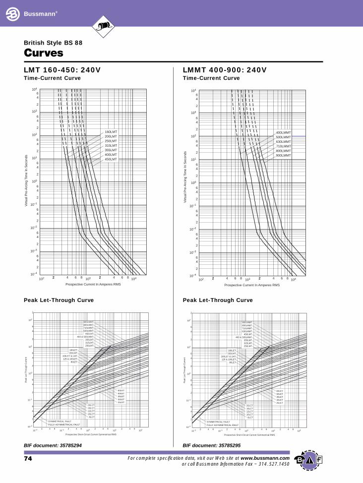
315LMT
450LMT400LMT355LMT
250LMT200LMT160LMT
Prospective Current In Amperes RMS
Virt
ual P
re-A
rcin
g Ti
me
In S
econ
ds
103
10–2
Prospective Short-Circuit Current Symmetrical RMS
10–2 10–12 64 2 4 6100 2 4 6
101 2 4 6102
Pea
k Le
t-T
hrou
gh C
urre
nt
10–2
6
2
4
2
10–1
4
6
2
100
6
4
101
6
4
2
2
102
SYMMETRICAL FAULT
FULLY ASYMMETRICAL FAULT
20LCT16LCT12LCT10LCT 6LCT
25LET32LET35LET50LET63LET
80LET125 & 100LET
160LET & LMT200LMT180LET
250LMT315LMT355LMT
400 & 500LMMT450LMT
630LMMT710LMMT800LMMT900LMMT
Peak Let-Through Curve
LMT 160-450: 240VTime-Current Curve
74 For complete specifica
BIF document: 35785294
10–1
10–3
10–2
102
103
104
102 22 4 6 8 2103 2 4 6 8 104
2
46
2
64
100
2
64
101
2
64
2
64
2
64
64
2
6
2
4
Prospective Current In Amperes RMS
Virt
ual P
re-A
rcin
g Ti
me
In S
econ
ds
10–4
710LMMT
900LMMT800LMMT
630LMMT500LMMT400LMMT
Prospective Short-Circuit Current Symmetrical RMS
10–2 10–12 64 2 4 6100 2 4 6
101 2 4 6102
Pea
k Le
t-T
hrou
gh C
urre
nt
10–2
6
2
4
2
10–1
4
6
2
100
6
4
101
6
4
2
2
102
SYMMETRICAL FAULT
FULLY ASYMMETRICAL FAULT
20LCT16LCT12LCT10LCT 6LCT
25LET32LET35LET50LET63LET
80LET125 & 100LET
160LET & LMT200LMT180LET
250LMT315LMT355LMT
400 & 500LMMT450LMT
630LMMT710LMMT800LMMT900LMMT
Peak Let-Through Curve
LMMT 400-900: 240VTime-Current Curve
tion data, visit our Web site at www.bussmann.comor call Bussmann Information Fax ~ 314.527.1450
BIF document: 35785295
British Style BS 88
Bussmann®
Curves
103
10–1
2 4 6 8 101 22 4 6 8 2102 2 4 6 8 103
2
46
2
64
100
2
64
101
2
64
2
64
2
64
64
2
6
2
4
10CT12CT16CT20CT
6CT
32ET25ET
Prospective Current In Amperes RMS
Virt
ual P
re-A
rcin
g Ti
me
In S
econ
ds
56ET
80ET63ET
45ET40ET35ET
10–4
10–3
10–2
102
104
Prospective Short-Circuit Current Symmetrical RMS
Pea
k Le
t-T
hrou
gh C
urre
nt
2
4
2
6
6
4
2
4
6
4
2
6
4
2
6
2 4 6 2 4 6 2 4 6 2 4 6101
102
103
104
105
101 102 103 104 105 2
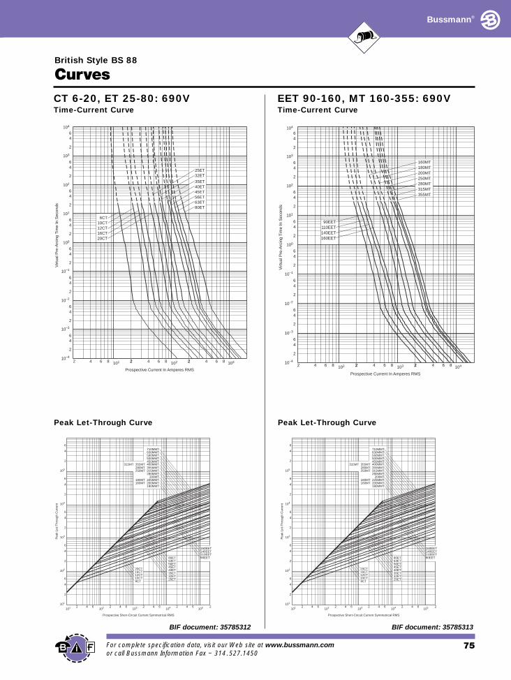
20CT16CT12CT10CT6CT
80ET63ET56ET45ET40ET35ET32ET25ET
710MMT630MMT560MMT500MMT450MMT
315MT 355MT 400MMT280MT 355MMT250MT 315MMT
280MMT 200MT
180MT 225MMT160MT 200MMT
180MMT
160EET140EET110EET90EET
Peak Let-Through Curve
CT 6-20, ET 25-80: 690VTime-Current Curve
For complete specification data, visit our Web site at or call Bussmann Information Fax ~ 314.527.1450
BIF document: 35785312
103
104
102
10–1
10–2
2 4 6 8 102 22 4 6 8 2103 2 4 6 8 104
2
46
2
64
100
2
64
101
2
64
2
64
2
64
64
2
6
2
4
Prospective Current In Amperes RMS
Virt
ual P
re-A
rcin
g Ti
me
In S
econ
ds
160EET140EET110EET90EET
200MT
355MT315MT280MT250MT
180MT160MT
10–4
10–3
Prospective Short-Circuit Current Symmetrical RMS
Pea
k Le
t-T
hrou
gh C
urre
nt
2
4
2
6
6
4
2
4
6
4
2
6
4
2
6
2 4 6 2 4 6 2 4 6 2 4 6101
102
103
104
105
101 102 103 104 105 2
20CT16CT12CT10CT6CT
80ET63ET56ET45ET40ET35ET32ET25ET
710MMT630MMT560MMT500MMT450MMT
315MT 355MT 400MMT280MT 355MMT250MT 315MMT
280MMT 200MT
180MT 225MMT160MT 200MMT
180MMT
160EET140EET110EET90EET
Peak Let-Through Curve
EET 90-160, MT 160-355: 690VTime-Current Curve
75www.bussmann.com
BIF document: 35785313
British Style BS 88
Bussmann®
Curves
104
103
102
10–1
10–3
Prospective Current In Amperes RMS
Vir
tual
Pre
-Arc
ing
Tim
e In
Sec
onds
102 22 4 6 8 2103 2 4 6 8 104
2
46
2
64
100
2
64
101
2
64
2
64
2
64
64
2
6
2
4
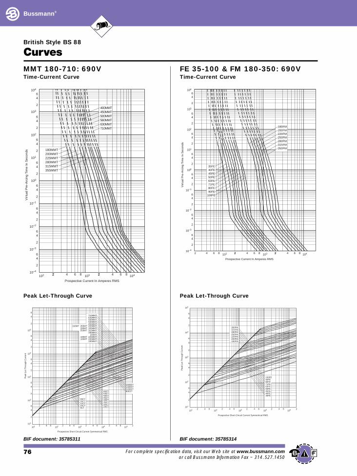
280MMT
355MMT315MMT
225MMT200MMT180MMT
630MMT710MMT
560MMT500MMT450MMT400MMT
10–4
10–2
MMT 180-710: 690VTime-Current Curve
Prospective Short-Circuit Current Symmetrical RMS
Pea
k Le
t-T
hrou
gh C
urre
nt
2
4
2
6
6
4
2
4
6
4
2
6
4
2
6
2 4 6 2 4 6 2 4 6 2 4 6101
102
103
104
105
101 102 103 104 105 2
20CT16CT12CT10CT6CT
80ET63ET56ET45ET40ET35ET32ET25ET
710MMT630MMT560MMT500MMT450MMT
315MT 355MT 400MMT280MT 355MMT250MT 315MMT
280MMT 200MT
180MT 225MMT160MT 200MMT
180MMT
160EET140EET110EET90EET
Peak Let-Through Curve
76 For complete specifica
BIF document: 35785311
103
102
10–1
10–2
10–4
2 4 6 8 102 22 4 6 8 2103 2 4 6 8 104
2
46
2
64
100
2
64
101
2
64
2
64
2
64
64
2
6
2
4
100FE
35FE40FE45FE50FE63FE71FE80FE90FE
350FM315FM280FM250FM220FM200FM180FM
Prospective Current In Amperes RMS
Vir
tual
Pre
-Arc
ing
Tim
e In
Sec
onds
10–3
104
FE 35-100 & FM 180-350: 690VTime-Current Curve
Prospective Short-Circuit Current Symmetrical RMS
Pea
k Le
t-T
hrou
gh C
urre
nt
2
4
2
6
6
4
2
6
4
2
6
4
2 4 6 2 4 6 2 4 6 2 4 6101
102
103
104
105
101 102 103 104 105 2
350FM315FM280FM250FM225FM200FM180FM
100FE90FE80FE71FE63FE50FE45FE40FE35FE
Peak Let-Through Curve
tion data, visit our Web site at www.bussmann.comor call Bussmann Information Fax ~ 314.527.1450
BIF document: 35785314
British Style BS 88
Bussmann®
Curves
104
103
102
10–1
10–2
10–3
10–4
102 22 4 6 8 2103 2 4 6 8 104
2
46
2
64
100
2
64
101
2
64
2
64
2
64
64
2
6
2
4
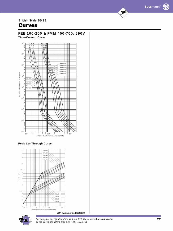
120FEE140FEE160FEE180FEE200FEE
100FEE
550FMM
700FMM630FMM
500FMM450FMM400FMM
Prospective Current In Amperes RMS
Virt
ual P
re-A
rcin
g Ti
me
In S
econ
ds
FEE 100-200 & FMM 400-700: 690VTime-Current Curve
Prospective Short-Circuit Current Symmetrical RMS
Pea
k Le
t-T
hrou
gh C
urre
nt
102 2 4 62
4
6
103
8
2
8
4
6
104
2
4
6
8
103 2 4 6104 2 4 6
105 2
180FEE
100FEE
120FEE
140FEE
160FEE
200FEE
400FMM
450FMM
500FMM
550FMM
630FMM
700FMM
Peak Let-Through Curve
77For complete specification data, visit our Web site at www.bussmann.comor call Bussmann Information Fax ~ 314.527.1450
BIF document: 35785292

North America’s leading supplier of fuses and fusible protection systems,
Bussmann continues its 80-year history of blazing new trails of innovative technologies.
Maker of the industry’s first truly global product line, each item is backed by an efficient
worldwide network of distribution, customer service and technical support. Bussmann products include the
most extensive circuit protection solutions that are built and tested to a variety of major standards: U.L.,
CSA, IEC, ISO. . . Additionally, both European (DIN, British Standard) and North American styled fuses are
used for a wide range of applications: industrial motor protection, power conversion, medium voltage power
distribution, telecommunications network equipment, electronics, and
automotive. Manufacturing operations in the U.S., Denmark, and the
United Kingdom have earned ISO 9000 certification, assuring
Bussmann customers only the utmost quality across every product line.
Knowledgeable. Responsive. Customer focused. Bussmann continues to
set the standard for circuit protection solutions in the global marketplace.
Bussmann—The Source For Global Solutions In Semiconductor Protection
Today’s power electronics market knows no international boundaries – so neither should the high speedfuses that are used to protect semiconductor devices.
Only one fuse maker – Bussmann – has the resources required to meet all of thepower conversion industry’s principle needs:
• Knowledgeable technical support • Global sourcing & manufacturing • Cutting-edge application design (certified to ISO 9000 standards)
Bussmann offers a comprehensive range of high speed fuselinks, specifically designed for semiconductordevice protection. These products use advanced materials and technology to deliver unsurpassed performance.
All high speed fuses carry the quality assurance of the Bussmann name – the recognizedworld leader in circuit protection.
This brochure summarizes the features and benefits of the following high speedfuses that Bussmann manufactures for the power electronics market:
• North American • European (DIN)• British • Ferrule
Worldwide Circuit Protection SolutionsBussmann®
This catalog is intended to present product data and provide technical information that will help the end user with design application.Bussmann reserves the right, without notice, to change design or construction of any products and to discontinue or limit distribution of any products. Bussmann also reserves the right to change or update, without notice, any technical information contained in this catalog.Once a product has been selected, it should be tested by the user in all possible applications.
©1998 Cooper Industries, Bussmann DivisionPrinted in the U.S.A.
Bussmann Brasil Bussmann do Brasil Ltda.Rodovia Santos Dumont, Km 2313 300-000 Cruz das AlmasCaixa Postal 95-ItuSao Paulo-BrasilTelephone: 55 11 7824 1722 Facsimile: 55 11 7824 1721
Bussmann Denmark5 Literbuen DK-2740 SkovlundeCopenhagen, DenmarkTelephone: 45 4485 0900Facsimile: 45 4485 0901
Bussmann India2nd Floor, Unit #5White House23-29, St. Marks RoadBangalore – 560-001IndiaTelephone: 91-80-227-0893Facsimile: 91-80-224-0124
Bussmann Mexico Arrow-Hart S.A. de C.V.Poniente 148, No. 93302300 Mexico, D.F. MexicoTelephone: 52 5 587 0211 Facsimile: 52 5 567 4049
HeadquartersCooper IndustriesBussmann DivisionP.O. Box 14460St. Louis, Missouri 63178-4460, USATelephone: 314-394-2877Facsimile: 800-544-2570
Bussmann Circuit Components7300 West Wilson AvenueChicago, IL 60656-4793, USATelephone: 708-867-4600Facsimile: 708-867-2211
European HeadquartersBussmann DivisionCooper (UK) LimitedBurton-on-the-WoldsLeicestershire LE12 5th, EnglandTelephone: 44 1509 882737Facsimile: 44 1509 882786
Bussmann Asia Pacific331 North Bridge Road#03-02 Odeon TowersSingapore 188720Republic of SingaporeTelephone: 65 336 3610Facsimile: 65 336 4810
Bussmann AustraliaBlock X391 Park RoadP.O. Box 257Regents Park, SydneyNSW 2143, AustraliaTelephone: 61 2 9743 8333Facsimile: 61 2 9743 8070
http://www.bussmann.com
Bussmann