Embed Size (px)
Citation preview
ELECTRICAL SAFETY SOLUTIONS /
HIGH-SPEED DC CIRCUIT BREAKERS Type UR26, UR36 & UR40 - 3 kVDC RAIL VEHICLES
S
HIGH-SPEED DC CIRCUIT BREAKERS, TYPE UR26, UR36 & UR40 - 3 KVDC2
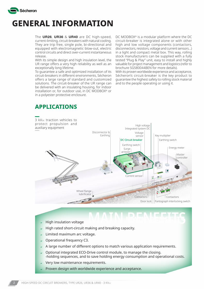
APPLICATIONS
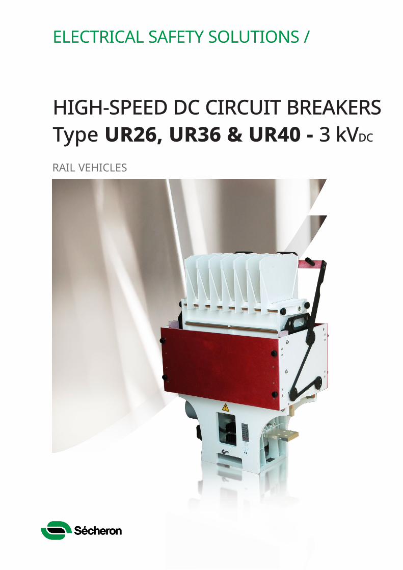
GENERAL INFORMATIONThe UR26, UR36 & UR40 are DC high-speed, current-limiting, circuit-breakers with natural cooling. They are trip free, single pole, bi-directional and equipped with electromagnetic blow-out, electric control circuits and direct over-current instantaneous release.With its simple design and high insulation level, the UR range offers a very high reliability as well as an exceptionally long lifetime.To guarantee a safe and optimized installation of its circuit-breakers in different environments, Sécheron offers a large range of standard and customized solutions. The circuit-breaker of the UR range can be delivered with an insulating housing, for indoor installation or, for outdoor use, in DC MODBOX® or in a polyester protective enclosure.
DC MODBOX® is a modular platform where the DC circuit-breaker is integrated alone or with other high and low voltage components (contactors, disconnectors, resistors, voltage and current sensors…) in a light and compact metal box. This way, rolling stock manufacturers can be supplied with a fully tested “Plug & Play” unit, easy to install and highly valuable for project management and logistics (refer to brochure SG580044BEN for more details).With its proven worldwide experience and acceptance, Sécheron’s circuit-breaker is the key product to guarantee the highest safety to rolling stock material and to the people operating or using it.
3 kVDC traction vehicles to protect propulsion and auxiliary equipment
High insulation voltage High rated short-circuit making and breaking capacity. Limited maximum arc voltage. Operational frequency C3. Alargenumberofdifferentoptionstomatchvariousapplicationrequirements. Optional integrated ECO-Drive control module, to manage the closing.
- holding sequences, and to save holding energy consumption and operational costs. Very low maintenance requirements. Proven design with worldwide experience and acceptance.
10
11
12
13
15
14
16
17
18
19
20
Trac
tion
Conv
erte
r
15/25 kVAC and 0.75/1.5/3.0 kVDC
DC
Link
Auxil
iary
Conv
erte
r
Train Roof Line
2
3
4
5
6
7
88
9
4
455
10
11
12
13
14
14
14
14
15
14
14
14
16
17 17 17
18
19
19
19
19
1
1
4
5
6
7
8
2 9
3
9 20
MAIN BENEFITSMAIN BENEFITS
Voltage sensor
Disconnector & Earthing
Wheel flange lubrificator
ContactorsDoor lock Pantograph interlocking switch
Contactors
Current sensor
DC Circuit breaker
Earthing switch
Earthing switch
Energy meter
Master controller
Key multiplier
Surge arrester
High voltageIntegrated system DC
HIGH-SPEED DC CIRCUIT BREAKERS, TYPE UR26, UR36 & UR40 - 3 KVDC 3
MAIN FEATURES• Rated operational voltage 3’600 VDC
• Conventional free air thermal current: 2’300 A (UR26), 3’600 A (UR36) and 4’000 A (UR40)
• Electro-magnetic closing with electric holding • Five double contacts auxiliary switches • Pollution degree PD3• Insulation material according to EN45545-2:2013• Reference standards: EN/IEC 60077-1/3, IEC77, IEC 61373
IEC-60077
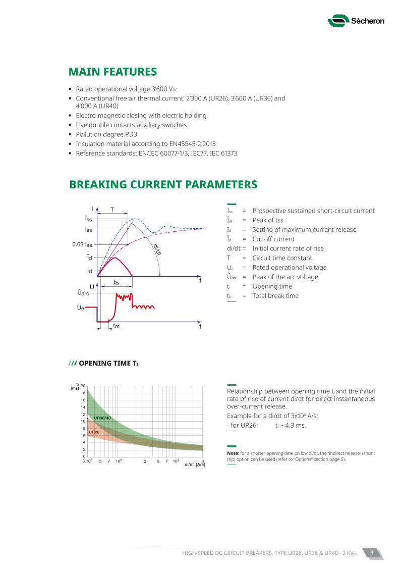
Id
Îd
Iss
0.63 Iss
Ut
ttm
I
tb
Îss
di/dt
T
Ûarc
Ue
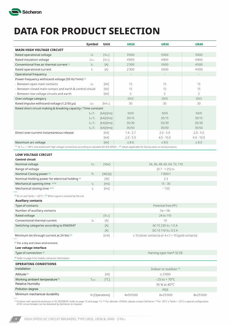
/// OPENING TIME TI
Iss = Prospective sustained short-circuit currentÎss = Peak of IssId = Setting of maximum current releaseÎd = Cut off currentdi/dt = Initial current rate of riseT = Circuit time constantUr = Rated operational voltageÛarc = Peak of the arc voltageti = Opening timetb = Total break time
20t l
t l
[ms]18
[ms]
16
14
12
10
8
6
4
2
03.105 5 7 53 37106 107
di/dt [A/s]
UR26
UR36/40
10
8
6
4
2
03.105 5 7 53 37106 107
di/dt [A/s]
UR60/80
Relationship between opening time tl and the initial rate of rise of current di/dt for direct instantaneous over-current release.Example for a di/dt of 3x10⁶ A/s:- for UR26: tl ~ 4.3 ms.
Note: for a shorter opening time on low di/dt, the “indirect release” (shunt trip) option can be used (refer to “Options” section page 5).
BREAKING CURRENT PARAMETERS
HIGH-SPEED DC CIRCUIT BREAKERS, TYPE UR26, UR36 & UR40 - 3 KVDC4
DATA FOR PRODUCT SELECTION
LOW VOLTAGE CIRCUITControl circuitNominal voltage Un [Vdc] 24, 36, 48, 60, 64, 72, 110Range of voltage [0.7 - 1.25] Un
Nominal Closing power (3) Pc [W]/[s] 1’300/1Nominal Holding power for electrical holding (9) [W] 2.3Mechanical opening time (3) (4) to [ms] 15 - 30Mechanical closing time (3) (4) tc [ms] ~ 150
(3) At Un and Tamb = +20°C • (4) When signal is received by the coil.
Auxiliary contactsType of contacts Potential free (PF)Number of auxiliary contacts 5a + 5bRated voltage [VDC] 24 to 110Conventional thermal current Ith [A] 10Switching categories according to EN60947 [A] AC-15 230 VAC 1.0 A [A] DC-13 110 VDC 0.5 AMinimum let-through current at 24 Vdc (5) [mA] ≥ 10 (silver contacts) or 4 ≤ I < 10 (gold contacts)
(5) For a dry and clean environment.
Low voltage interface
Type of connection (6) Harting type Han® 32 EE(6) Refer to page 5 for mobile connector information.
OPERATING CONDITIONSInstallation Indoor or outdoor (7)
Altitude (8) [m] ≤ 2’000Working ambient temperature (9) Tamb [°C] - 25 to + 70°CRelative Humidity 95 % at 40°CPollution degree PD3Minimum mechanical durability N [Operations] 4x50’000 8x25’000 8x25’000
(7) Outdoor with optional enclosure or DC MODBOX® (refer to page 10 and page 11). (8) For altitude >2’000m, please contact Sécheron. (9) For -50°C ≤ Tamb < -25°C a special configuration of DC circuit-breaker can be delivered by Sécheron on request.
Symbol Unit UR26 UR36 UR40
MAIN HIGH VOLTAGE CIRCUITRated operational voltage Ur [VDC] 3’600 3’600 3’600Rated insulation voltage UNm [VDC] 4’800 4’800 4’800Conventional free air thermal current (1) Ith [A] 2’300 3’600 4’000Rated operational current Ir [A] 2’300 3’600 4’000Operational frequency - - -Power-frequency withstand voltage (50 Hz/1min) (2) - Between open main contacts Ua [kV] 15 15 15- Between closed main contact and earth & control circuit [kV] 15 15 15- Between low voltage circuits and earth [kV] 2 2 2Over-voltage category OV3 OV3 OV3Ratedimpulsewithstandvoltage(1.2/50μs) UNi [kVDC] 30 30 30Rated short-circuit making & breaking capacity / Time constant
ISS/T1 [kA]/[ms] 50/0 50/0 50/0ISS/T2 [kA]/[ms] 35/15 35/15 35/15ISS/T3 [kA]/[ms] 35/30 35/30 35/30ISS/T4 [kA]/[ms] 35/50 35/50 35/50
Direct over-current instantaneous release [kA] 1.4 - 2.7 2.0 - 5.0 2.0 - 5.0[kA] 2.0 - 5.0 4.0 - 10.0 4.0 - 10.0
Maximum arc voltage [kV] ≤ 8.0 ≤ 8.0 ≤ 8.0(1) At Tamb = +40°C and tested with high voltage connections according to standard IEC/EN 60943. • (2) Values applicable for factory tests on serial products.
HIGH-SPEED DC CIRCUIT BREAKERS, TYPE UR26, UR36 & UR40 - 3 KVDC 5
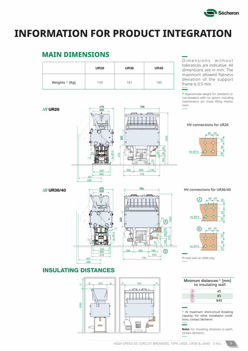
(1) Approximate weight for standard cir-cuit-breakers with no option, including maintenance arc chute lifting mecha-nism.
UR26 UR36 UR40
Weights (1) [Kg] 159 181 185
(1)
(1)
B
A
486
1035
457
4x Ø
14
761
300 185
255
206
37595
100
30
150
13
320 365379
478478320320
320
320
700700
A
B
55
(1) Heat sink on UR40 only
40 25
2550
25
4x Ø14
4x Ø14
40 25
2050
25
A
40 25
2550
25
4x Ø14
B
/// UR26
/// UR36/40
INFORMATION FOR PRODUCT INTEGRATION
D i m e n s i o n s w i t h o u t tolerances are indicative. All dimensions are in mm. The maximum allowed flatness deviation of the support frame is 0.5 mm.
HV connections for UR26
HV connections for UR36/40
MAIN DIMENSIONS
419 (81)
617 (82)238
A AB B
C78
4
320
A A
C B B B B
700
320
1035
1030
320C B B
1030
(1)
240 A A
C B B B B 700240
A A700
(1) At maximum short-circuit breaking capacity. For other installation condi-tions, contact Sécheron.
INSULATING DISTANCES
Note: For insulating distances to earth, contact Sécheron.
Minimum distances (1) [mm] to insulating wall
45 85
845
700700
320
320
320320478478
140206320
486
4x Ø
14 9520
160
1035
725
300
370
95
1355
365457
HIGH-SPEED DC CIRCUIT BREAKERS, TYPE UR26, UR36 & UR40 - 3 KVDC6
LOW VOLTAGE CONTROL SCHEME
/// ELECTRIC HOLDING E-TYPE
• The circuit breaker remains closed with a reduced ‘’holding’’ current. To open the circuit breaker the holding current is cut-off.
• With E-type closing device, the circuit breaker cannot remain closed if the low voltage supply is lost.
Ie
~ 20%
100%
0
0
0,5 1 tc tc+1tc+0.5
t [s]
DBA
C
–
+
~ 5%
100%
0 0,5 1
t [s]
SV=
R1
E
F
G
B CA
DIe
E
B
C
A
D
–
SV=+
Rs
Maintien magnétique pour UR60/80(maintien électrique idem que UR26-36-40-46)
UR60/80
UR26/36/40/46
Rs
RpF1
F2 E2
E1
SV=
–
+
E1
E2
F1
F2
Customer scope
Ie
~ 20%
100%
0
0
0,5 1 tc tc+1tc+0.5
t [s]
DBA
C
–
+
~ 5%
100%
0 0,5 1
t [s]
SV=
R1
E
F
G
B CA
DIe
E
B
C
A
D
–
SV=+
Rs
Maintien magnétique pour UR60/80(maintien électrique idem que UR26-36-40-46)
UR60/80
UR26/36/40/46
Rs
RpF1
F2 E2
E1
SV=
–
+
E1
E2
F1
F2
Sécheron scope
F, G : control contactsR1 : holding resistorS : automatic circuit breaker
Ie
~ 20%
100%
0
0
0,5 1 tc tc+1tc+0.5
t [s]
DBA
C
–
+
~ 5%
100%
0 0,5 1
t [s]
SV=
R1
E
F
G
B CA
DIe
E
B
C
A
D
–
SV=+
Rs
Maintien magnétique pour UR60/80(maintien électrique idem que UR26-36-40-46)
UR60/80
UR26/40/46
Rs
RpF1
F2 E2
E1
SV=
–
+
E1
E2
F1
F2
Rs
RpF1
F2 E2
E1
SV=
–
+
UR26/40/46/60/80
RUR
/// TYPICAL VALUE FOR CLOSING COILS
Note: for components selection, the fol-lowing criteria shall apply:
Unom = RxInom for Tamb = +20°C Umin = RxImin for Tamb = - 5°C Umax = RxImax for Tamb = +40°C (R = Resistance)
Coil characteristics
Closing pulse 0.5 to 1s holding E-type
Unom Inom Imin E Imin M Imax R1nom Inom Imin Imax
[VDC] [A] [A] [A] [A] [Ω] [A] [A] [A]
24 41.7 22.5 25 70.9 11.4 2.0 1.4 2.5
36 32.7 17.7 19.6 55.6 25 1.4 0.1 1.7
48 20.9 11.3 12.5 35.4 45.7 1.0 0.7 1.3
64 17.6 9.5 10.6 29.9 79.4 0.8 0.5 1.0
72 16.4 8.8 9.8 27.8 100 0.7 0.5 0.9
110 11.7 6.3 7.0 19.9 210 0.5 0.4 0.6
Note: The duration of the closing pulse (E-type) as well as the opening pulse should be 0.5 - 1 s.
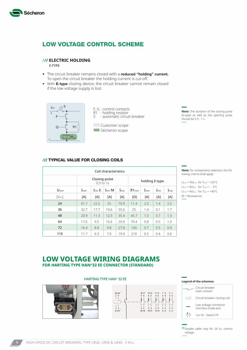
HARTING TYPE HAN® 32 EE
11 9
12 8
7 5 3 1
4
15
16
1319
20 10 6 21418
17
21
22
23
24(1)
(1)
(1) Double cable only for 24 VDC control voltage.
LOW VOLTAGE WIRING DIAGRAMS FOR HARTING TYPE HAN®32 EE CONNECTOR (STANDARD)
II>(WI)
a
b
a
b
(I>) (WI)a b a bHARTING
Brochure Brochure HARTINGHARTINGHARTING
Circuit breaker main contact
II>(WI)
a
b
a
b
(I>) (WI)a b a bHARTING
Brochure Brochure HARTINGHARTINGHARTING
Circuit breaker closing coil
II>(WI)
a
b
a
b
(I>) (WI)a b a bHARTING
Brochure Brochure HARTINGHARTINGHARTING
Low voltage connector interface (male pin)
II>(WI)
a
b
a
b
(I>) (WI)a b a bHARTING
Brochure Brochure HARTINGHARTINGHARTING
1a+1b - Switch PF
Legend of the schemes:
HIGH-SPEED DC CIRCUIT BREAKERS, TYPE UR26, UR36 & UR40 - 3 KVDC 7
Note:- Available for UR26/36/40- Available for closing device
with E-type holding
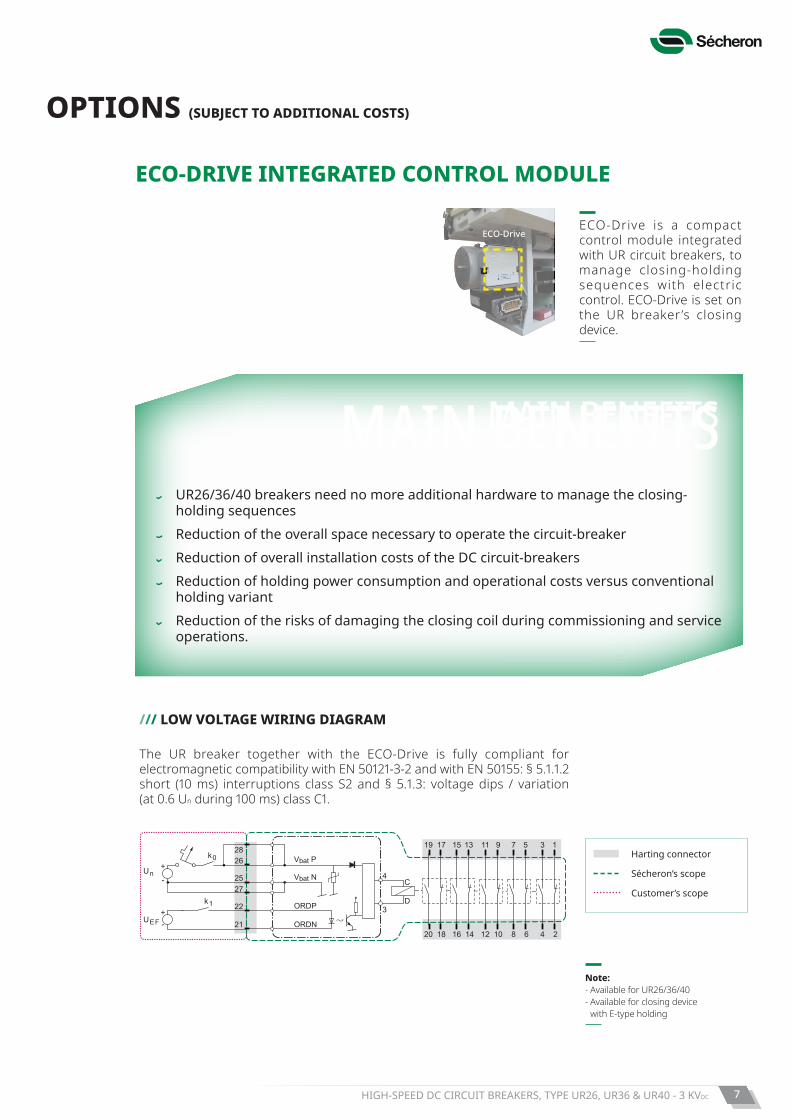
/// LOW VOLTAGE WIRING DIAGRAM
20
4
3
C
D
18 16 14
19 17
2628
2527
22
21
15 13
12 10 8 6
11 9 7 5
4 2
3 1
Vbat P
Vbat N
ORDP
ORDN
k0
Un
UEF
k1
+
+
-
-
Harting connector
Sécheron’s scope
Customer’s scope
The UR breaker together with the ECO-Drive is fully compliant for electromagnetic compatibility with EN 50121-3-2 and with EN 50155: § 5.1.1.2 short (10 ms) interruptions class S2 and § 5.1.3: voltage dips / variation (at 0.6 Un during 100 ms) class C1.
OPTIONS (SUBJECT TO ADDITIONAL COSTS)
MAIN BENEFITSMAIN BENEFITS
ECO-DRIVE INTEGRATED CONTROL MODULE
ECO-DriveECO-Drive is a compact control module integrated with UR circuit breakers, to manage closing-holding sequences with electric control. ECO-Drive is set on the UR breaker ’s closing device.
UR26/36/40 breakers need no more additional hardware to manage the closing-holding sequences
Reduction of the overall space necessary to operate the circuit-breaker Reduction of overall installation costs of the DC circuit-breakers Reduction of holding power consumption and operational costs versus conventional
holding variant Reduction of the risks of damaging the closing coil during commissioning and service
operations.
HIGH-SPEED DC CIRCUIT BREAKERS, TYPE UR26, UR36 & UR40 - 3 KVDC8
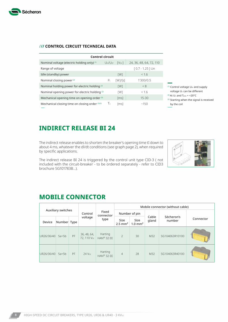
MOBILE CONNECTOR
Auxiliary switchesControl voltage
Fixedconnector
type
Mobile connector (without cable)
Number of pinCablegland
Sécheron’snumber Connector
Device Number Type Size2.5 mm²
Size1.0 mm²
UR26/36/40 5a+5b PF 36, 48, 64, 72, 110 VDC
Harting HAN® 32 EE
2 30 M32 SG104063R10100
UR26/36/40 5a+5b PF 24 VDCHarting
HAN® 32 EE4 28 M32 SG104063R40100
/// CONTROL CIRCUIT TECHNICAL DATA
Control circuit
Nominal voltage (electric holding only) (1) UN/UEF [VDC] 24, 36, 48, 64, 72, 110
Range of voltage [ 0.7 - 1.25 ] Un
Idle (standby) power [W] < 1.6
Nominal closing power (2) Pc [W]/[s] 1’300/0.5
Nominal holding power for electric holding (2) [W] < 8
Nominal opening power for electric holding (2) [W] < 1.6
Mechanical opening time on opening order (3) [ms] 15-30
Mechanical closing time on closing order (2)(3) Tc [ms] ~150
(1) Control voltage UEF and supply voltage Un can be different
(2) At Un and Tamb = +20°C(3) Starting when the signal is received
by the coil
The indirect release enables to shorten the breaker’s opening time tI down to about 4 ms, whatever the dl/dt conditions (see graph page 2), when required by specific applications.
The indirect release BI 24 is triggered by the control unit type CID-3 ( not included with the circuit-breaker - to be ordered separately - refer to CID3 brochure SG101783B...).
INDIRECT RELEASE BI 24
HIGH-SPEED DC CIRCUIT BREAKERS, TYPE UR26, UR36 & UR40 - 3 KVDC 9
Sécheron proposes 3 different concepts to integrate the UR26/36/40 circuit-breakers in vehicles:• Complete Plug & Play Roof-mounted polyester enclosure, in which
the DC circuit-breaker is installed, and which offers an IP54 protection index. It is intended for EMUs and trains outdoor roof mounting (including high speed trains).
• Insulation housing with protection index IP00, delivered as an option separately from the breaker. It enables the car-builder to build its own metal enclosure and/or container with reduced dimensions, in which the DC circuit-breaker with its insulation housing will be installed. This type is mostly used for locomotives and trains.
• Complete Plug & Play metal enclosure (DC MODBOX® program), in which the DC circuit-breaker is set with other functions, such as current & voltage measurements. DC MODBOX® offers an IP56 protection index for outdoor roof or underframe mounting. This type is mostly used for trains and high-speed trains, as well as for applications with severe operational environments (cold and icy, dusty or sandy environment).
CONCEPTS FOR INTEGRATION ON VEHICLES
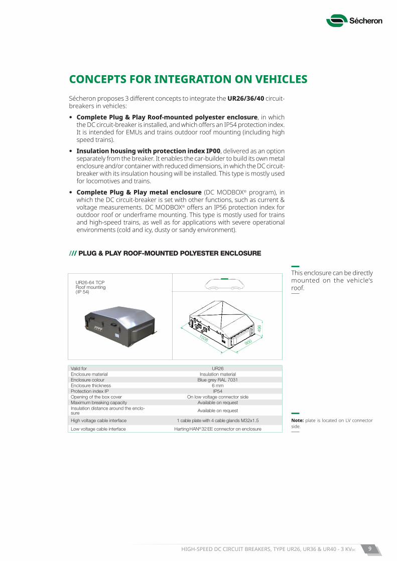
/// PLUG & PLAY ROOF-MOUNTED POLYESTER ENCLOSURE
Valid for UR26Enclosure material Insulation materialEnclosure colour Blue grey RAL 7031Enclosure thickness 6 mmProtection index IP IP54Opening of the box cover On low voltage connector sideMaximum breaking capacity Available on requestInsulation distance around the enclo-sure Available on request
High voltage cable interface 1 cable plate with 4 cable glands M32x1.5
Low voltage cable interface Harting HAN® 32 EE connector on enclosure
This enclosure can be directly mounted on the vehicle’s roof.
Note: plate is located on LV connector side.
UR26-64 TCP Roof mounting ( IP 54)
496
9001508
HIGH-SPEED DC CIRCUIT BREAKERS, TYPE UR26, UR36 & UR40 - 3 KVDC10
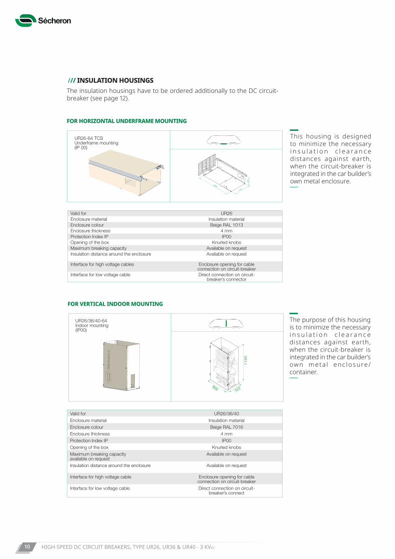
This housing is designed to minimize the necessary i n s u l a t i o n c l e a r a n c e distances against earth, when the circuit-breaker is integrated in the car builder’s own metal enclosure.
FOR HORIZONTAL UNDERFRAME MOUNTING
FOR VERTICAL INDOOR MOUNTING
Valid for UR26Enclosure material Insulation materialEnclosure colour Beige RAL 1013Enclosure thickness 4 mmProtection Index IP IP00Opening of the box Knurled knobsMaximum breaking capacity Available on requestInsulation distance around the enclosure Available on request
Interface for high voltage cables Enclosure opening for cable connection on circuit-breaker
Interface for low voltage cable Direct connection on circuit-breaker’s connector
Valid for UR26/36/40Enclosure material Insulation materialEnclosure colour Beige RAL 7016Enclosure thickness 4 mmProtection Index IP IP00Opening of the box Knurled knobsMaximum breaking capacity available on request
Available on request
Insulation distance around the enclosure Available on request
Interface for high voltage cable Enclosure opening for cable connection on circuit-breaker
Interface for low voltage cable Direct connection on circuit-breaker’s connect
UR26-64 TCSUnderframe mounting(IP 00)
900
1767
545
525
977
998
500 816
1524
1500
770
470
1500
770
470
The purpose of this housing is to minimize the necessary i n s u l a t i o n c l e a r a n c e distances against earth, when the circuit-breaker is integrated in the car builder’s own meta l enc losure/container.
/// INSULATION HOUSINGSThe insulation housings have to be ordered additionally to the DC circuit-breaker (see page 12).
UR26/36/40-64Indoor mounting (IP00)
503800
1160
HIGH-SPEED DC CIRCUIT BREAKERS, TYPE UR26, UR36 & UR40 - 3 KVDC 11
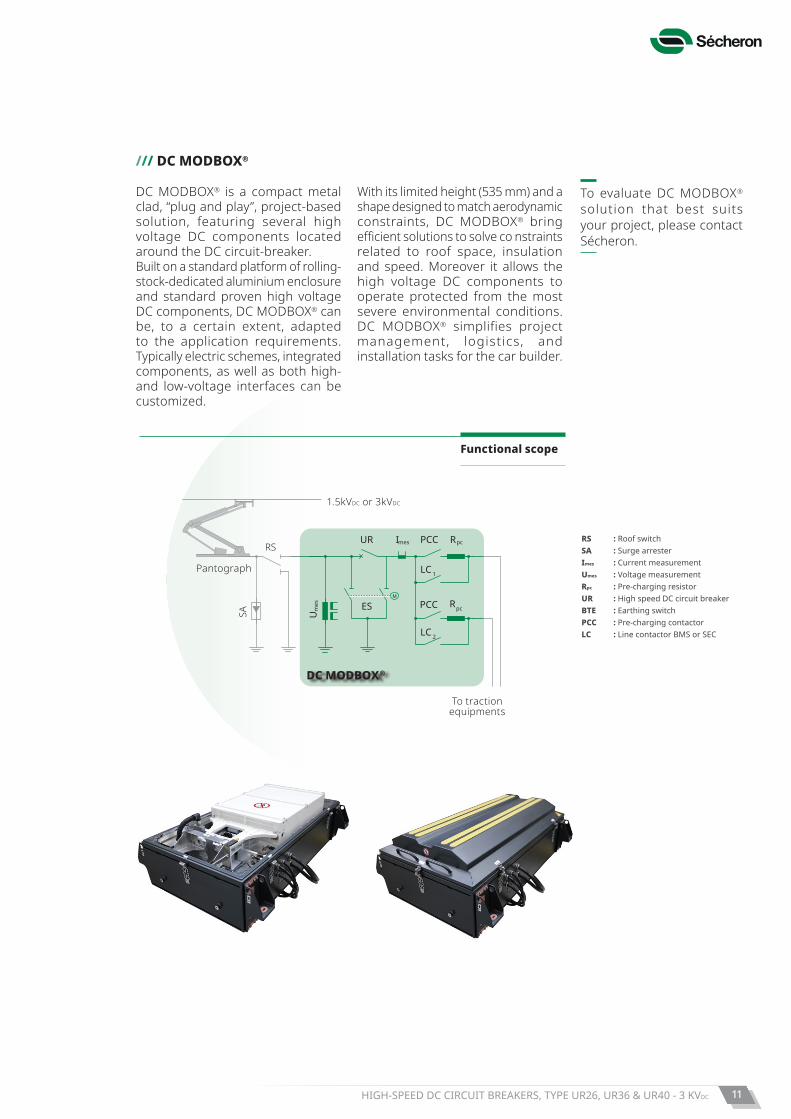
/// DC MODBOX®
To evaluate DC MODBOX® solution that best suits your project, please contact Sécheron.
DC MODBOX® is a compact metal clad, “plug and play’’, project-based solution, featuring several high voltage DC components located around the DC circuit-breaker.Built on a standard platform of rolling-stock-dedicated aluminium enclosure and standard proven high voltage DC components, DC MODBOX® can be, to a certain extent, adapted to the application requirements. Typically electric schemes, integrated components, as well as both high- and low-voltage interfaces can be customized.
With its limited height (535 mm) and a shape designed to match aerodynamic constraints, DC MODBOX® bring efficient solutions to solve co nstraints related to roof space, insulation and speed. Moreover it allows the high voltage DC components to operate protected from the most severe environmental conditions. DC MODBOX® simplifies project management, logistics, and installation tasks for the car builder.
RS : Roof switchMACS : Main AC switchAC VCB : AC vacuum circuit-breaker (MACS)ES : Earthing switch (MACS) SA : Surge arester I mes : Current measurement Umes : Voltage measurement Rpc : Pre-charging resistorUR : High speed DC circuit breaker BTE : Earthing switchPCC : Pre-charging contactorLC : Line contactor BMS or SEC
DC MODBOX®
UR
ES
RSRpcPCC
LC 1
RpcPCC
LC 2
Um
es
SA
Imes
1.5kVDC or 3kVDC
Pantograph
To tractionequipments
Functional scope
RS : Roof switchSA : Surge arrester Imes : Current measurementUmes : Voltage measurementRpc : Pre-charging resistorUR : High speed DC circuit breakerBTE : Earthing switchPCC : Pre-charging contactorLC : Line contactor BMS or SEC
Copyright© 2019 Sécheron SA
This document is not contractual and contains information corresponding to the level of technology at the date of printing. Sécheron reserves the right to modify and/or improve the product, whose characteristics are described in these documents, as required by new technology at any time. It is the purchaser’s responsibility to inform himself, no matter what the circumstances, of the product’s maintenance conditions and requirements. Sécheron reserves all rights, especially those arising from our “General Delivery Conditions”.
SG
10
53
06
BE
N_A
05
-03
.19
Sécheron SA Rue du Pré-Bouvier 251242 Satigny - GenevaCH-Switzerland
Tel: +41 22 739 41 11Fax: +41 22 739 48 [email protected]
Pla
ce a
nd d
ate:
N
ame:
S
igna
ture
:
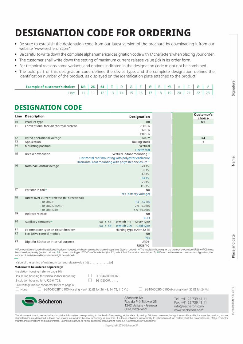
DESIGNATION CODELine Description Designation Standard Options Customer’s
choice10 Product type UR UR UR11 Conventional free air thermal current 2’300 A 26
3’600 A 364’000 A 40
12 Rated operational voltage 3’600 V 64 6413 Application Rolling stock T T14 Mounting position Vertical D
Horizontal C15 Breaker execution Vertical indoor mounting (1) Ø
Horizontal roof mounting with polyester enclosure P Horizontal roof mounting with polyester enclosure (2) S
16 Nominal Control voltage 24 VDC A36 VDC B48 VDC C64 VDC G72 VDC D
110 VDC E17 Varistor in coil (3) No Ø
Yes (battery voltage) 118 Direct over-current release (bi-directional)
For UR26 1.4 - 2.7 kA AFor UR26/36/40 2.0 - 5.0 kA BFor UR36/40 4.0- 10.0 kA G
19 Indirect release No ØBI24 1
20 Auxiliary contacts (4) 5a + 5b - (switch PF) - Silver type A5a + 5b - (switch CO) - Gold type C
21 LV connector type on circuit breaker Harting type HAN® 32 EE C22 Eco-Drive control module No Ø
Yes 423 Digit for Sécheron internal purpose UR26 V
UR36/40 A(1) For execution ordered with additional insulation housing, the housing must be ordered separately (section below) • (2) The insulation housing for the breaker’s execution UR26-64TCS must be ordered separately (section below) • (3) In case control type “ECO-Drive” is selected (line 22), select “No” for varistor on coil (line 17)• (4) Based on the selected breaker’s configuration, the number of available auxiliary switches might be reduced•
DESIGNATION CODE FOR ORDERING• Be sure to establish the designation code from our latest version of the brochure by downloading it from our
website “www.secheron.com”.• Be careful to write down the complete alphanumerical designation code with 17 characters when placing your order.• The customer shall write down the setting of maximum current release value (Id) in its order form.• For technical reasons some variants and options indicated in the designation code might not be combined.• The bold part of this designation code defines the device type, and the complete designation defines the
identification number of the product, as displayed on the identification plate attached to the product.
Example of customer’s choice: UR 26 64 T D Ø E Ø B Ø A C Ø V
Line: 11 11 12 13 14 15 16 17 18 19 20 21 22 23
Value of the setting of maximum current release value (Id): . . . . . . . . . . . . . . [A]Material to be ordered separetely:-Insulation housing (refer to page 10):Insulation housing for vertical indoor mounting: SG104420R00002 Insulation housing for UR26-64TCS: SG102006R. . . . .
-Low voltage mobile connector (refer to page 8): None SG104063R10100 (Harting Han® 32 EE for 36, 48, 64, 72, 110 Vdc) SG104063R40100 (Harting Han® 32 EE for 24 Vdc)