Embed Size (px)
Citation preview
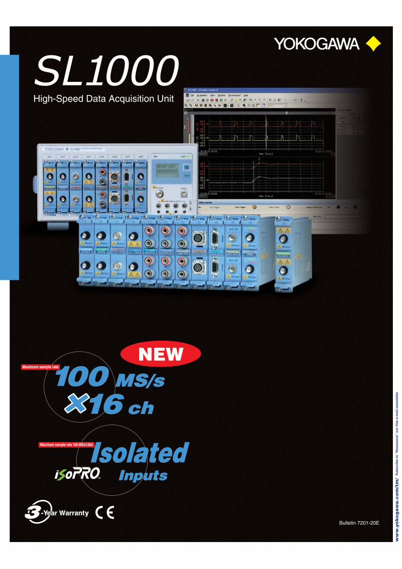
High-Speed Data Acquisition Unit
Bulletin 7201-20E
100100 MS/sMS/sMaximum sample rate
1616 chch
IsolatedIsolatedInputsInputs
Maximum sample rate 100 MS/s12bit
NEW
-Year Warrantear Warranty-Year Warranty
ww
w.y
oko
ga
wa
.co
m/t
m/
Su
bsc
rib
e to
"N
ewsw
ave"
ou
r fr
ee e
-mai
l new
slet
ter
Fast Acquisition, Transfer, and S torageFinally, a No-Compromise, High-P erformance Data Acquisition Unit
03
02
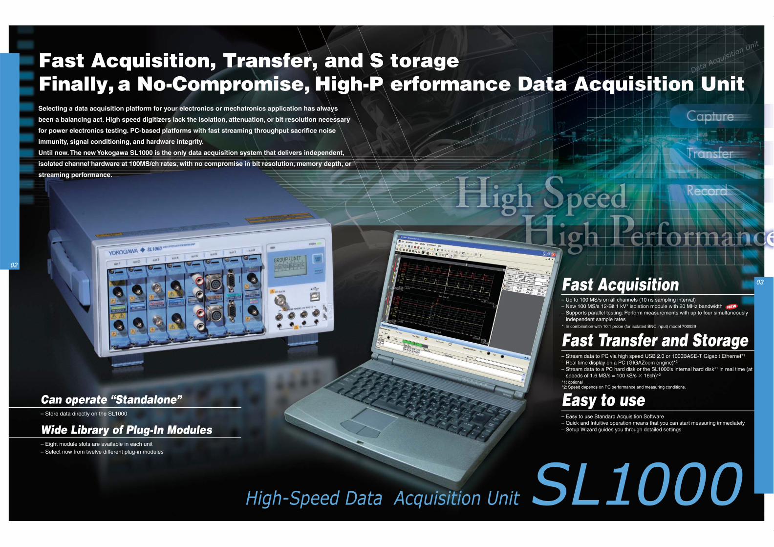
Selecting a data acquisition platform for your electronics or mechatronics application has always
been a balancing act. High speed digitizers lack the isolation, attenuation, or bit resolution necessary
for power electronics testing. PC-based platforms with fast streaming throughput sacrifice noise
immunity, signal conditioning, and hardware integrity.
Until now. The new Yokogawa SL1000 is the only data acquisition system that delivers independent,
isolated channel hardware at 100MS/ch rates, with no compromise in bit resolution, memory depth, or
streaming performance.
– Up to 100 MS/s on all channels (10 ns sampling interval)– New 100 MS/s 12-Bit 1 kV* isolation module with 20 MHz bandwidth– Supports parallel testing: Perform measurements with up to four simultaneously
independent sample rates
– Store data directly on the SL1000
– Eight module slots are available in each unit– Select now from twelve different plug-in modules
– Stream data to PC via high speed USB 2.0 or 1000BASE-T Gigabit Ethernet*1
– Real time display on a PC (GIGAZoom engine)*2
– Stream data to a PC hard disk or the SL1000's internal hard disk*1 in real time (atspeeds of 1.6 MS/s = 100 kS/s 16ch)*2
– Easy to use Standard Acquisition Software– Quick and Intuitive operation means that you can start measuring immediately– Setup Wizard guides you through detailed settings
*: In combination with 10:1 probe (for isolated BNC input) model 700929
*1: optional*2: Speed depends on PC performance and measuring conditions.
Fast Acquisition
Fast Transfer and Storage
Easy to useCan operate “Standalone”
Wide Library of Plug-In Modules
NEW
High-Speed
Easy to use — Software —
— Hardware —
SL1000
High-Speed
Easy to use — Software —
— Hardware —
05
04
– Fast AcquisitionUp to 100 MS/s on all channels10 ns sampling intervalNew: 100 MS/s 12-Bit isolation moduleSupports parallel testing
– Fast Transfer and StorageUSB 2.0 or 1000BASE-T (optional)Real time display on a PC (GIGAZoom engine)Save data to a hard disk in real time
– Easy to use Standard Acquisition Software
Plug and Play: Auto-recognition of units andmodulesQuick and Intuitive operationSetup Wizard guides you through detailed settings
– Analysis FunctionsReal time waveform analysisOffline waveform computation (optional)
High-Speed Data Acquisition Unit
High speedphenomena
Waveform accurately captured
High sample rate (100 MS/s)20 MHz bandwidth
Example Setup
4 sample rates
Installmodules into
unit
Connectto PC
Start Acquisition SoftwareUnit and modules
automatically recognized
Select unit andmodule
Start measurement
Setup Wizard
Start measurement
Power ON
Click
USB/Ethernet*2
*1
PC monitor display(triggered measurement)
Real time full-length display
Zoom displayInstantaneous display,whether stopped or running
Record Specified Durations of Data atSpecific Intervals
Record Data Every Trigger
Hard diskrecording
Measureddata(memory)
Recordings= 3
Record start
Recording time
Recording intervalRecord stop
Hard diskrecording
Measureddata(memory)
Trigger
Record startMeasurement time
Pretrigger
Control ButtonsRecord start/Divide/Stop
Measurement start/stop Display hold /restartDefine waveform equations using a number of basic and advanced functions.
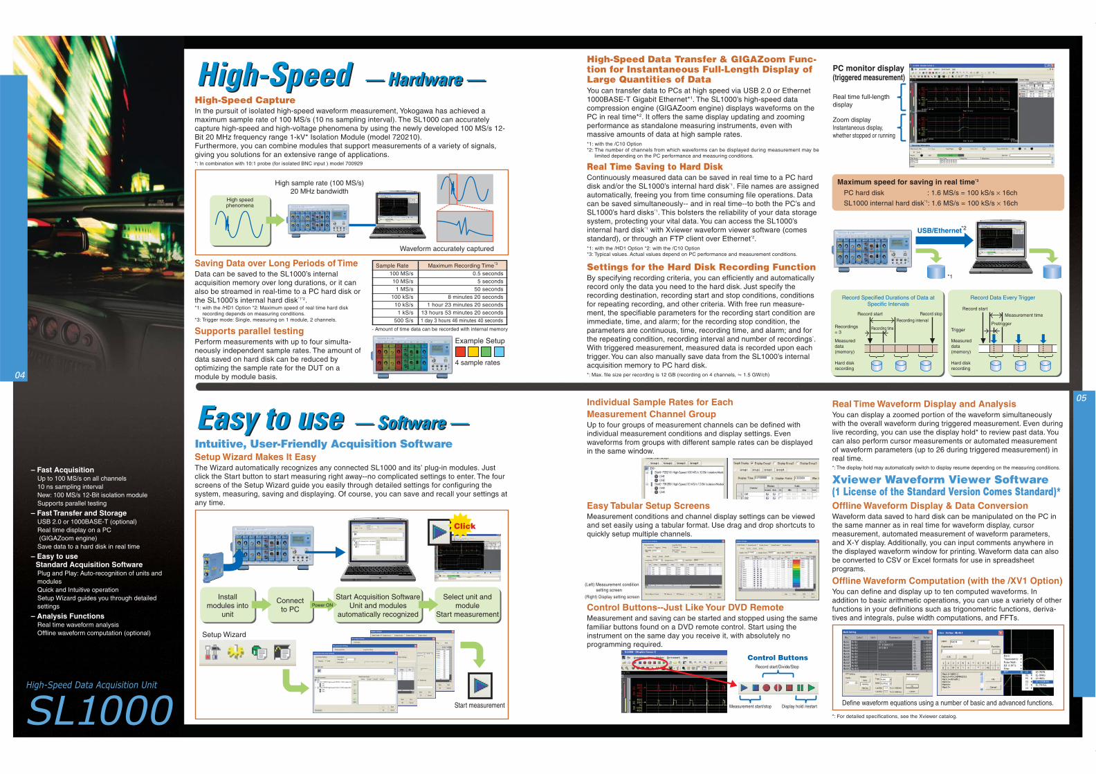
High-Speed CaptureIn the pursuit of isolated high-speed waveform measurement, Yokogawa has achieved amaximum sample rate of 100 MS/s (10 ns sampling interval). The SL1000 can accuratelycapture high-speed and high-voltage phenomena by using the newly developed 100 MS/s 12-Bit 20 MHz frequency range 1-kV* Isolation Module (model 720210).Furthermore, you can combine modules that support measurements of a variety of signals,giving you solutions for an extensive range of applications.
Saving Data over Long Periods of TimeData can be saved to the SL1000’s internalacquisition memory over long durations, or it canalso be streamed in real-time to a PC hard disk orthe SL1000’s internal hard disk*1*2.*1: with the /HD1 Option *2: Maximum speed of real time hard disk
recording depends on measuring conditions.*3: Trigger mode: Single, measuring on 1 module, 2 channels.
Maximum speed for saving in real time*3
PC hard disk : 1.6 MS/s = 100 kS/s × 16ch
SL1000 internal hard disk*1: 1.6 MS/s = 100 kS/s × 16ch
*1: with the /HD1 Option *2: with the /C10 Option*3: Typical values. Actual values depend on PC performance and measurement conditions.
Intuitive, User-Friendly Acquisition Software
Easy Tabular Setup ScreensMeasurement conditions and channel display settings can be viewedand set easily using a tabular format. Use drag and drop shortcuts toquickly setup multiple channels.
Individual Sample Rates for EachMeasurement Channel GroupUp to four groups of measurement channels can be defined withindividual measurement conditions and display settings. Evenwaveforms from groups with different sample rates can be displayedin the same window.
Control Buttons--Just Like Your DVD RemoteMeasurement and saving can be started and stopped using the samefamiliar buttons found on a DVD remote control. Start using theinstrument on the same day you receive it, with absolutely noprogramming required.
(Left) Measurement conditionsetting screen
(Right) Display setting screen
*: In combination with 10:1 probe (for isolated BNC input ) model 700929
Sample Rate Maximum Recording Time*3
100 MS/s 0.5 seconds10 MS/s 5 seconds
1 MS/s 50 seconds100 kS/s 8 minutes 20 seconds
10 kS/s 1 hour 23 minutes 20 seconds1 kS/s 13 hours 53 minutes 20 seconds
500 S/s 1 day 3 hours 46 minutes 40 seconds
Supports parallel testingPerform measurements with up to four simulta-neously independent sample rates. The amount ofdata saved on hard disk can be reduced byoptimizing the sample rate for the DUT on amodule by module basis.
*1: with the /C10 Option*2: The number of channels from which waveforms can be displayed during measurement may be
limited depending on the PC performance and measuring conditions.
High-Speed Data Transfer & GIGAZoom Func-tion for Instantaneous Full-Length Display ofLarge Quantities of DataYou can transfer data to PCs at high speed via USB 2.0 or Ethernet1000BASE-T Gigabit Ethernet*1. The SL1000’s high-speed datacompression engine (GIGAZoom engine) displays waveforms on thePC in real time*2. It offers the same display updating and zoomingperformance as standalone measuring instruments, even withmassive amounts of data at high sample rates.
Settings for the Hard Disk Recording FunctionBy specifying recording criteria, you can efficiently and automaticallyrecord only the data you need to the hard disk. Just specify therecording destination, recording start and stop conditions, conditionsfor repeating recording, and other criteria. With free run measure-ment, the specifiable parameters for the recording start condition areimmediate, time, and alarm; for the recording stop condition, theparameters are continuous, time, recording time, and alarm; and forthe repeating condition, recording interval and number of recordings*.With triggered measurement, measured data is recorded upon eachtrigger. You can also manually save data from the SL1000’s internalacquisition memory to PC hard disk.
Setup Wizard Makes It EasyThe Wizard automatically recognizes any connected SL1000 and its’ plug-in modules. Justclick the Start button to start measuring right away--no complicated settings to enter. The fourscreens of the Setup Wizard guide you easily through detailed settings for configuring thesystem, measuring, saving and displaying. Of course, you can save and recall your settings atany time.
Real Time Waveform Display and AnalysisYou can display a zoomed portion of the waveform simultaneouslywith the overall waveform during triggered measurement. Even duringlive recording, you can use the display hold* to review past data. Youcan also perform cursor measurements or automated measurementof waveform parameters (up to 26 during triggered measurement) inreal time.*: The display hold may automatically switch to display resume depending on the measuring conditions.
Xviewer Waveform Viewer Software(1 License of the Standard Version Comes Standard)*Offline Waveform Display & Data ConversionWaveform data saved to hard disk can be manipulated on the PC inthe same manner as in real time for waveform display, cursormeasurement, automated measurement of waveform parameters,and X-Y display. Additionally, you can input comments anywhere inthe displayed waveform window for printing. Waveform data can alsobe converted to CSV or Excel formats for use in spreadsheetprograms.
Offline Waveform Computation (with the /XV1 Option)You can define and display up to ten computed waveforms. Inaddition to basic arithmetic operations, you can use a variety of otherfunctions in your definitions such as trigonometric functions, deriva-tives and integrals, pulse width computations, and FFTs.
Real Time Saving to Hard DiskContinuously measured data can be saved in real time to a PC harddisk and/or the SL1000’s internal hard disk*1. File names are assignedautomatically, freeing you from time consuming file operations. Datacan be saved simultaneously-- and in real time--to both the PC’s andSL1000’s hard disks*1. This bolsters the reliability of your data storagesystem, protecting your vital data. You can access the SL1000’sinternal hard disk*1 with Xviewer waveform viewer software (comesstandard), or through an FTP client over Ethernet*2.
- Amount of time data can be recorded with internal memory
*: Max. file size per recording is 12 GB (recording on 4 channels, 1.5 GW/ch)
*: For detailed specifications, see the Xviewer catalog.
ApplicationsApplications
ModulesModules07
06
– Can operate “Standalone”Store data directly on the SL1000
– A wide range of Plug-In Modules8 module slots are available in each unitNew: 100 MS/s 12-Bit isolation moduleSupports all 11 ScopeCorder series modulesSelect now from 12 different plug-in modules
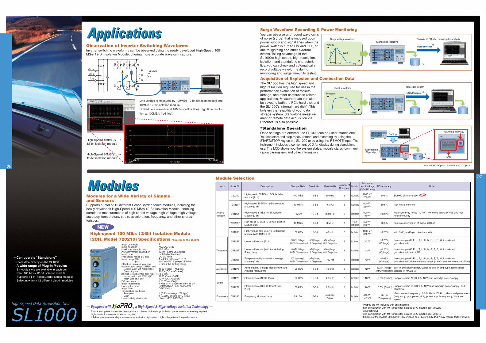
Acquisition of Explosion and Combustion DataThe SL1000 has the high speed andhigh resolution required for use in theperformance evaluation of rockets,airbags, and other combustion-relatedapplications. Measured data can alsobe saved to both the PC’s hard disk andthe SL1000's internal hard disk*1. Thisbolsters the reliability of your datastorage system. Standalone measure-ment or remote data acquisition viaEthernet*2 is also possible.
— Equipped with , a High-Speed & High-Voltage Isolation Technology —This is Yokogawa's latest technology that achieves high voltage isolation performance where high-speedhigh-resolution measurement is required.It takes you to a new stage in measurement with high-speed high-voltage isolation performance.
R
C
E
G
C
E
G
S
T
UMOTOR
V
W
C
E
G
C
E
G
C
E
G
C
E
G
Transfer to PC after recording for analysisSurge voltage waveform
*1
Voltage
Time
~50µs
~1µs
USB/Ethernet*2
Standalone recording
USB/Ethernet
Recorded to bothShock waveform
*2
*1
Pressure
Time
High-Speed 100MS/s 12-bit isolation module
High-Speed 10MS/s 12-bit isolation module
High-Speed 100MS/s 12-bit isolation module
High-Speed 10MS/s 12-bit isolation module
Setting
LCD
START/STOP key
StandaloneOperatipn
*1
*1: with the /HD1 Option *2: with the /C10 Option
Surge Waveform Recording & Power MonitoringYou can observe and record waveformsof noise (surge) that is imposed uponpower supply and signal lines when thepower switch is turned ON and OFF, ordue to lightning and other externalevents. Taking advantage of theSL1000's high speed, high resolution,isolation, and standalone characteris-tics, you can check and automaticallyrecord voltage waveforms duringmonitoring and surge immunity testing.
*Standalone OperationOnce settings are entered, the SL1000 can be used “standalone”.You can start and stop measurement and recording by using theSTART/STOP key on the SL1000 or by using the REMOTE input. Theinstrument includes a convenient LCD for display during standaloneuse. The LCD shows you the system status, module status, communi-cation parameters, and other information.
Observation of Inverter Switching WaveformsInverter switching waveforms can be observed using the newly developed High-Speed 100MS/s 12-Bit Isolation Module, offering more accurate waveform capture.
Line voltage is measured by 100MS/s 12-bit isolation module and
10MS/s 12-bit isolation module.
Limited time resolution at 10MS/s (yellow line). High time resolu-
tion at 100MS/s (red line).
Input channelsInput couplingMaximum sample rateA/D conversion resolutionInput typeFrequency range (-3 dB)Input range (10:1) (1:1)Effective measuring rangeMaximum input voltage (1 kHz or less)
In combination with 700929 (10:1)Direct input (1:1)
Maximum allowable common mode voltage (1 kHz or less)In combination with 700929 (10:1)Main unit only (1:1)
DC accuracyInput impedanceConnector typeInput filterTemperature coefficient
Zero pointGain
Laser safety standards
Modules for a Wide Variety of Signalsand Sensors
High-speed 100 MS/s 12-Bit Isolation Module(2CH, Model 720210) Specifications *Specific to the SL1000
NEW
Supports a total of 12 different ScopeCorder series modules, including thenewly developed High-Speed 100 MS/s 12-Bit Isolation Module, enablingcorrelated measurements of high speed voltage, high voltage, high voltageaccuracy, temperature, strain, acceleration, frequency, and other charac-teristics.
2AC, DC, GND100 MS/s12-bit (1,500 LSB/range)Isolated unbalancedDC-20 MHz1 V-2 kV (steps of 1-2-5)100 mV-200 V (steps of 1-2-5)2 times the setting range
1000 V (DC + ACpeak)200 V (DC + ACpeak)
1000 Vrms (CATII)42 V (DC+ACpeak)± (0.5% of range)1 MΩ ±1%, approximately 35 pFIsolated type BNC connectorOFF/2 MHz
± (0.1% of range)/°C (typ.)± (0.02% of range)/°C (typ.)class 1 (IEC 60825-1)
Model No.
720210
701250*4
701251
701255*4
701260
701261
701262
701265
701275
701270
701271
701280
Input
Temperature
Acceleration
Strain
Frequency
AnalogVoltage
Note
SL1000 exclusive use
high noise immunity
High sensitivity range (10 mV), low noise (±100 µVtyp), and high noise immunity
non-isolation version of model 701250
with RMS, and high noise immunity
thermocouple (K, E, J, T, L, U, N, R, S, B, W, iron-doped gold/chromel)
thermocouple (K, E, J, T, L, U, N, R, S, B, W, iron-doped gold/chromel), with AAF
thermocouple (K, E, J, T, L, U, N, R, S, B, W, iron-doped gold/chromel), high sensitivity range (1 mV), and low noise (±4 µVtyp)
built-in anti-aliasing filter, Supports built-in amp type acceleration sensors (4 mA/22 V)
Supports strain NDIS, 2,5, 10 V built-in bridge power supply
Supports strain DSUB, 2,5, 10 V built-in bridge power supply, and shunt CAL
Measurement frequency of 0.01 Hz to 200 kHz, Measured parameters (frequency, rpm, period, duty, power supply frequency, distance, speed)
DC Accuracy
±0.5%
±0.5%
±0.25%
±0.5%
±0.25%
±0.25% (Voltage)
±0.25% (Voltage)
±0.08% (Voltage)
±0.25% (Voltage)±0.5% (Acceleration)
±0.5% (Strain)
±0.5% (Strain)
±0.1% (Frequency)
Maximum Input Voltage (DC+ACpeak)
1000 V*1
200 V*2
600 V*1
250 V*2
600 V*1
140 V*2
600 V*3
250 V*2
1000 V*1
850 V*2
42 V
42 V
42 V
42 V
10 V
10 V
420 V*1
42 V*2
Isolation
Isolated
Isolated
Isolated
Non-isolated
Isolated
Isolated
Isolated
Isolated
Isolated
Isolated
Isolated
Isolated
Number of Channels
2
2
2
2
2
2
2
2
2
2
2
2
Bandwidth
20 MHz
3 MHz
300 kHz
3 MHz
40 kHz
40 kHz (Voltage) 100 Hz (Temperature)
40 kHz (Voltage) 100 Hz (Temperature)
100 Hz
40 kHz
20 kHz
20 kHz
resolution50 ns
Resolution
12-Bit
12-Bit
16-Bit
12-Bit
16-Bit
16-Bit (Voltage), 0.1°C (Temperature)
16-Bit (Voltage), 0.1°C (Temperature)
16-Bit (Voltage), 0.1°C (Temperature)
16-Bit
16-Bit
16-Bit
16-Bit
Sample Rate
100 MS/s
10 MS/s
1 MS/s
10 MS/s
100 kS/s
100 kS/s (Voltage), 500 S/s (Temperature)
100 kS/s (Voltage), 500 S/s (Temperature)
500 S/s (Voltage), 500 S/s (Temperature)
100 kS/s
100 kS/s
100 kS/s
25 kS/s
Description
High-speed 100 MS/s 12-Bit Isolation Module (2 ch)
High-speed 10 MS/s 12-Bit Isolation Module (2 ch)
High-speed 1 MS/s 16-Bit Isolation Module (2 ch)
High-speed 10 MS/s 12-Bit non-Isolation Module (2 ch)
High-voltage 100 kS/s 16-Bit Isolation Module (with RMS, 2 ch)
Universal Module (2 ch)
Universal Module (with Anti-Aliasing Filter, 2 ch)
Temperature/high-precision voltage Module (2 ch)
Acceleration / Voltage Module (with Anti-Aliasing Filter, 2 ch)
Strain module (NDIS, 2 ch)
Strain module (DSUB, Shunt-CAL, 2 ch)
Frequency Module (2 ch)
* Probes are not included with any modules.*1: In combination with 10:1 probe (for isolated BNC input) model 700929*2: Direct input*3: In combination with 10:1 probe (for isolated BNC input) model 701940*4: Some of the models 701250/701255 shipped on or before July, 2007 may require factory rework.
NEW
Module Selection
100 MS/s16 ch
IsolatedInputs
-Year WarrantySubject to change without notice.[Ed : 01/b] Copyright ©2007
Printed in Japan, 712(KP)
YOKOGAWA ELECTRIC CORPORATIONCommunication & Measurement Business Headquarters /Phone: (81)-422-52-6768, Fax: (81)-422-52-6624E-mail: [email protected] CORPORATION OF AMERICA Phone: (1)-770-253-7000, Fax: (1)-770-251-6427YOKOGAWA EUROPE B.V. Phone: (31)-33-4641858, Fax: (31)-33-4641859YOKOGAWA ENGINEERING ASIA PTE. LTD. Phone: (65)-62419933, Fax: (65)-62412606 MS-16E
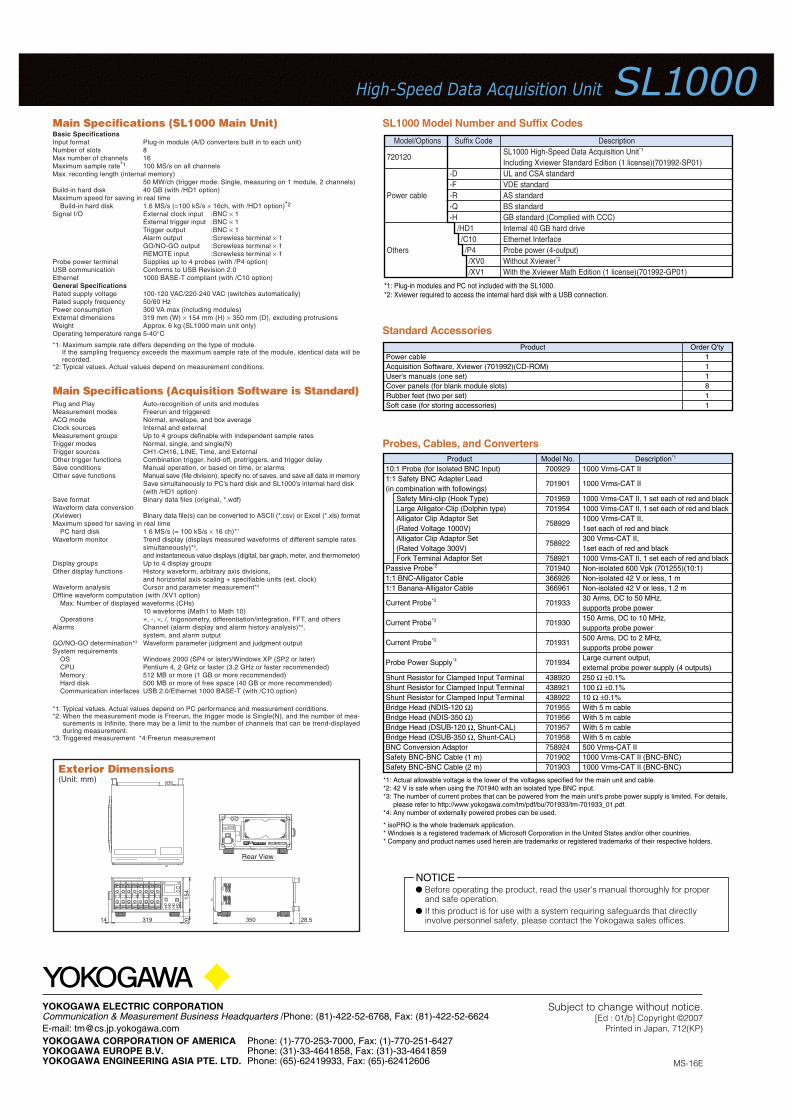
SL1000 Model Number and Suffix CodesBasic SpecificationsInput format Plug-in module (A/D converters built in to each unit)Number of slots 8Max number of channels 16Maximum sample rate*1 100 MS/s on all channelsMax. recording length (internal memory)
50 MW/ch (trigger mode: Single, measuring on 1 module, 2 channels)Build-in hard disk 40 GB (with /HD1 option)Maximum speed for saving in real time
Build-in hard disk 1.6 MS/s (=100 kS/s × 16ch, with /HD1 option)*2
Signal I/O External clock input :BNC × 1External trigger input :BNC × 1Trigger output :BNC × 1Alarm output :Screwless terminal × 1GO/NO-GO output :Screwless terminal × 1REMOTE input :Screwless terminal × 1
Probe power terminal Supplies up to 4 probes (with /P4 option)USB communication Conforms to USB Revision 2.0Ethernet 1000 BASE-T compliant (with /C10 option)General SpecificationsRated supply voltage 100-120 VAC/220-240 VAC (switches automatically)Rated supply frequency 50/60 HzPower consumption 300 VA max (including modules)External dimensions 319 mm (W) × 154 mm (H) × 350 mm (D), excluding protrusionsWeight Approx. 6 kg (SL1000 main unit only)Operating temperature range 5-40°C
Main Specifications (SL1000 Main Unit)
*1: Maximum sample rate differs depending on the type of module.If the sampling frequency exceeds the maximum sample rate of the module, identical data will berecorded.
*2: Typical values. Actual values depend on measurement conditions.
Plug and Play Auto-recognition of units and modulesMeasurement modes Freerun and triggeredACQ mode Normal, envelope, and box averageClock sources Internal and externalMeasurement groups Up to 4 groups definable with independent sample ratesTrigger modes Normal, single, and single(N)Trigger sources CH1-CH16, LINE, Time, and ExternalOther trigger functions Combination trigger, hold-off, pretriggers, and trigger delaySave conditions Manual operation, or based on time, or alarmsOther save functions Manual save (file division), specify no. of saves, and save all data in memory
Save simultaneously to PC’s hard disk and SL1000’s internal hard disk(with /HD1 option)
Save format Binary data files (original, *.wdf)Waveform data conversion(Xviewer) Binary data file(s) can be converted to ASCII (*.csv) or Excel (*.xls) formatMaximum speed for saving in real time
PC hard disk 1.6 MS/s (= 100 kS/s × 16 ch)*1
Waveform monitor Trend display (displays measured waveforms of different sample ratessimultaneously)*2,and instantaneous value displays (digital, bar graph, meter, and thermometer)
Display groups Up to 4 display groupsOther display functions History waveform, arbitrary axis divisions,
and horizontal axis scaling + specifiable units (ext. clock)Waveform analysis Cursor and parameter measurement*3
Offline waveform computation (with /XV1 option)Max. Number of displayed waveforms (CHs)
10 waveforms (Math1 to Math 10)Operations +, -, ×, /, trigonometry, differentiation/integration, FFT, and others
Alarms Channel (alarm display and alarm history analysis)*4,system, and alarm output
GO/NO-GO determination*3 Waveform parameter judgment and judgment outputSystem requirements
OS Windows 2000 (SP4 or later)/Windows XP (SP2 or later)CPU Pentium 4, 2 GHz or faster (3.2 GHz or faster recommended)Memory 512 MB or more (1 GB or more recommended)Hard disk 500 MB or more of free space (40 GB or more recommended)Communication interfaces USB 2.0/Ethernet 1000 BASE-T (with /C10 option)
Main Specifications (Acquisition Software is Standard)
*1: Typical values. Actual values depend on PC performance and measurement conditions.*2: When the measurement mode is Freerun, the trigger mode is Single(N), and the number of mea-
surements is Infinite, there may be a limit to the number of channels that can be trend-displayedduring measurement.
*3: Triggered measurement *4:Freerun measurement
Model No.700929
701901
701959701954
758929
758922
758921701940366926366961
701933
701930
701931
701934
438920438921438922701955701956701957701958758924701902701903
Product10:1 Probe (for Isolated BNC Input)1:1 Safety BNC Adapter Lead(in combination with followings)
Safety Mini-clip (Hook Type)Large Alligator-Clip (Dolphin type)Alligator Clip Adaptor Set(Rated Voltage 1000V)Alligator Clip Adaptor Set(Rated Voltage 300V)Fork Terminal Adaptor Set
Passive Probe*2
1:1 BNC-Alligator Cable1:1 Banana-Alligator Cable
Current Probe*3
Current Probe*3
Current Probe*3
Probe Power Supply*4
Shunt Resistor for Clamped Input TerminalShunt Resistor for Clamped Input TerminalShunt Resistor for Clamped Input TerminalBridge Head (NDIS-120 Ω)Bridge Head (NDIS-350 Ω)Bridge Head (DSUB-120 Ω, Shunt-CAL)Bridge Head (DSUB-350 Ω, Shunt-CAL)BNC Conversion AdaptorSafety BNC-BNC Cable (1 m)Safety BNC-BNC Cable (2 m)
Description*1
1000 Vrms-CAT II
1000 Vrms-CAT II
1000 Vrms-CAT II, 1 set each of red and black1000 Vrms-CAT II, 1 set each of red and black1000 Vrms-CAT II, 1set each of red and black300 Vrms-CAT II, 1set each of red and black1000 Vrms-CAT II, 1 set each of red and blackNon-isolated 600 Vpk (701255)(10:1)Non-isolated 42 V or less, 1 mNon-isolated 42 V or less, 1.2 m30 Arms, DC to 50 MHz, supports probe power150 Arms, DC to 10 MHz, supports probe power500 Arms, DC to 2 MHz, supports probe powerLarge current output, external probe power supply (4 outputs)250 Ω ±0.1%100 Ω ±0.1%10 Ω ±0.1%With 5 m cableWith 5 m cableWith 5 m cableWith 5 m cable500 Vrms-CAT II1000 Vrms-CAT II (BNC-BNC)1000 Vrms-CAT II (BNC-BNC)
*1: Actual allowable voltage is the lower of the voltages specified for the main unit and cable.*2: 42 V is safe when using the 701940 with an isolated type BNC input.*3: The number of current probes that can be powered from the main unit's probe power supply is limited. For details,
please refer to http://www.yokogawa.com/tm/pdf/bu/701933/tm-701933_01.pdf.*4: Any number of externally powered probes can be used.
* isoPRO is the whole trademark application.* Windows is a registered trademark of Microsoft Corporation in the United States and/or other countries.* Company and product names used herein are trademarks or registered trademarks of their respective holders.
DescriptionSL1000 High-Speed Data Acquisition Unit*1
Including Xviewer Standard Edition (1 license)(701992-SP01)UL and CSA standardVDE standardAS standardBS standardGB standard (Complied with CCC)Internal 40 GB hard driveEthernet InterfaceProbe power (4-output)Without Xviewer*2
With the Xviewer Math Edition (1 license)(701992-GP01)
Suffix Code
-D-F-R-Q-H
/HD1/C10/P4/XV0/XV1
Model/Options
720120
Power cable
Others
*1: Plug-in modules and PC not included with the SL1000.*2: Xviewer required to access the internal hard disk with a USB connection.
NOTICE Before operating the product, read the user's manual thoroughly for proper
and safe operation. If this product is for use with a system requiring safeguards that directly
involve personnel safety, please contact the Yokogawa sales offices.
Standard Accessories
Probes, Cables, and Converters
Exterior Dimensions(Unit: mm)
Rear View
14 319 2015
4
350 28.5
ProductPower cableAcquisition Software, Xviewer (701992)(CD-ROM)User's manuals (one set)Cover panels (for blank module slots)Rubber feet (two per set)Soft case (for storing accessories)
Order Q'ty111811


![7201 Song Chap5 [Compatibility Mode]](https://img.pdfslide.us/doc/110x75/577d2a871a28ab4e1ea96df3/7201-song-chap5-compatibility-mode.jpg)
