Embed Size (px)
Citation preview
Ind
ust
rial E
lectr
ical En
gin
eerin
g a
nd
A
uto
matio
n
CODEN:LUTEDX/(TEIE-7244)/1-18/(2013)
High speed brushless PMSM forin-fan application
Damia-2 application status report
Underrubrik
Avo Reinap
Division of Industrial Electrical Engineering and Automation Faculty of Engineering, Lund University
A.R. 1-18
IEA/LTH DAMIA-2: Fan Applications 2013/Dec
High speed brushless PMSM for fan application This is a reviewing document (a progress report on Damia-2) on design and evaluation of an outer rotor surface mounted permanent magnet synchronous machine for fan drive application. As the matter of fact, the machine design has been influenced on the achievements on the design and manufacturing of:
1. Outer rotor machine for In-wheel application
2. Development and realization of wave-windings for electrical machines
The specific outcome to the machine design and manufacturing of the machine has resulted to
1. Systematic 2D FEA scan trough of the distributed concentrated windings and core material combinations for the specified size of the machine
2. 3D FEA comparison between distributed concentrated windings and axially distributed wave-winding with a few material combinations
3. Machine prototyping with the unique approach of molding the insulation system in prior to core analysis and the final specification of the winding
High speed brushless PMSM for fan application............................................................................................1
1 Manufacturing, design and target specifications....................................................................................2
1.1 Size and power specification................................................................................................................2
1.2 Machine topology specification...........................................................................................................3
2 Design process ............................................................................................................................................4
2.1 Initialization............................................................................................................................................4
2.2 Concentrated winding specification ...................................................................................................5
2.3 Comparison between wave-winding and distributed concentrated winding ...............................7
2.4 Machine characteristics.......................................................................................................................10
3 Manufacturing and assembling process ................................................................................................13
3.1 Machine parts .......................................................................................................................................13
3.2 SM2C core molded around temporal support structure................................................................14
3.3 SM2C core molded around the main insulation system ................................................................15
3.4 Machine assembling ............................................................................................................................15
4 Evaluation process ...................................................................................................................................16
5 Conclusions and future work .................................................................................................................17
References............................................................................................................................................................18
A.R. 2-18
IEA/LTH DAMIA-2: Fan Applications 2013/Dec
1 Manufacturing, design and target specifications The advantages of not repeating the potential traps in the design and manufacturing process turned to be disadvantages to the complete evaluation of the high speed brushless PMSM for fan application. Namely the design realization of the electrical machine for in-wheel application showed that even if it is easy to mould the SM2C core around the mechanically locked windings there are much more concerns on
1. preceding manufacturing of the modular winding or the chain of the concentrated coils, especially for high fill factor and low number of turns
2. Establishing the main insulation system around the winding, between the package of wires and the molded core, there a few tests showing that the main insulation does not hold insulation voltage reguirements
3. Not acceptable tolerances of the components, especially coils and windings, that has to be placed into the mold in prior to molding
4. Last but not least the molding process, feedstock preparation, the mould design and production is not completely developed that can be adapted to various sizes and specially designed cores with inserts
As a result, the selection of the manufacturing approach for this machine is not the repetition of the preceding course of actions; if not innovative then the new process is unconventional and adds to the design for manufacturability knowledge of the machines with molded AC cores. The steps and the motivation behind is as following
1. Starting from the design and the electromechanical energy conversion it is believed that the modular winding is the most suitable for the core with low magnetic permeability
2. Instead of trying to solve the production of the high fill factor modular winding with appropriate insulation system that gives (very) good tolerances and high dielectric strength the main insulation is inserted to the mould and the core is molded to the “right side” of the insulation system.
3. The insulation system is 3D printed from the CAD drawing and dielectrically reinforced by coating with the layer of epoxy
4. Pure SM2C rotomolded core is selected and no magnetic or mechanical reinforcement system is added. It is known that the torque capability is low and this could be improved by adding simple geometries of magnetic inserts but this would make the manufacturing process much more complex according to previous experiences. In extreme it would exclude SM2C completely, use laminated core and reduce electric loading considerably for the same torque level that the machine gives with SM2C. As a matter of fact but this is considered to be out of the project scope as the goals are to explore the moldable soft magnetic composites, molding processes and their suitability for machine cores.
5. The predefined core with insulation system is contra revolutionary as it is the traditional way of making machines. The advantage of the premade core and the insulation system is that there is the exact structure to form and to wind the winding, thus there are no additional steps to build bobbins, patterns or constructions to produce windings or add the premade segments together. The only troublesome production step is to succeed hand made high fill factor windings inside the slotted structure of the stator core.
1.1 Size and power specification The predecessor PMSM with SM2C core for in-wheel application has appeared with various diameters in order do adjust to the specific features of the core that have inherently low permeability and low power loss. The most manufactured size is Do/Di-Hact, 310/240-60 mm. The high speed brushless PMSM for fan application has quite strict size specification Do/Di-Hact, 175/90-100 mm.
A.R. 3-18
IEA/LTH DAMIA-2: Fan Applications 2013/Dec
The outer radius has slightly increased from the initial specification and the resulting active length Hact is the outcome of the mechanical design and construction to respect actual space limitation. The inner radius is basically the size related parameter only that the electromagnetic design could influence. The machine should be able to deliver 10 kW at 6000 rpm and the driver voltage is as high as 600 V. The machine supposes to be “naturally cooled”. As a matter of fact, the machine is part of the fan application, where the machine is part of the forced cooling that it supposes to provide.
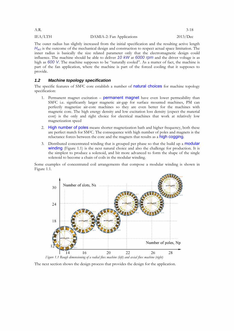
1.2 Machine topology specification The specific features of SM2C core establish a number of natural choices for machine topology specification:
1. Permanent magnet excitation – permanent magnet have even lower permeability than SM2C i.e. significantly larger magnetic air-gap for surface mounted machines, PM can perfectly magnetize air-core machines so they are even better for the machines with magnetic core. The high energy density and low excitation loss density (expect the material cost) is the only and right choice for electrical machines that work at relatively low magnetization speed
2. High number of poles means shorter magnetization bath and higher frequency, both these are perfect match for SM2C. The consequence with high number of poles and magnets is the reluctance forces between the core and the magnets that results as a high cogging.
3. Distributed concentrated winding that is grouped per phase so that the build up a modular winding (Figure 1.1) is the next natural choice and also the challenge for production. It is the simplest to produce a solenoid, and bit more advanced to form the shape of the single solenoid to become a chain of coils in the modular winding.
Some examples of concentrated coil arrangements that compose a modular winding is shown in Figure 1.1.
Figure 1.1 Rough dimensioning of a radial flux machine (left) and axial flux machine (right)
The next section shows the design process that provides the design for the application.
A.R. 4-18
IEA/LTH DAMIA-2: Fan Applications 2013/Dec
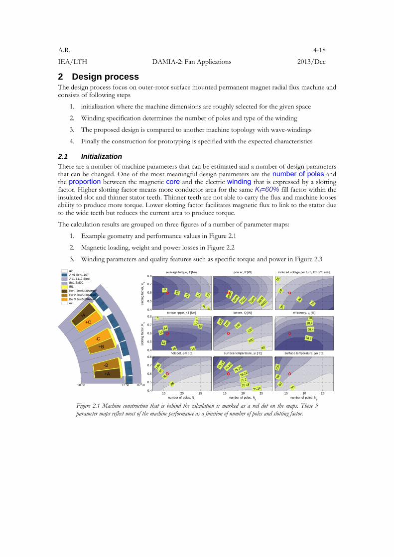
2 Design process The design process focus on outer-rotor surface mounted permanent magnet radial flux machine and consists of following steps
1. initialization where the machine dimensions are roughly selected for the given space
2. Winding specification determines the number of poles and type of the winding
3. The proposed design is compared to another machine topology with wave-windings
4. Finally the construction for prototyping is specified with the expected characteristics
2.1 Initialization There are a number of machine parameters that can be estimated and a number of design parameters that can be changed. One of the most meaningful design parameters are the number of poles and the proportion between the magnetic core and the electric winding that is expressed by a slotting factor. Higher slotting factor means more conductor area for the same Kf=60% fill factor within the insulated slot and thinner stator teeth. Thinner teeth are not able to carry the flux and machine looses ability to produce more torque. Lower slotting factor facilitates magnetic flux to link to the stator due to the wide teeth but reduces the current area to produce torque.
The calculation results are grouped on three figures of a number of parameter maps:
1. Example geometry and performance values in Figure 2.1
2. Magnetic loading, weight and power losses in Figure 2.2
3. Winding parameters and quality features such as specific torque and power in Figure 2.3
+A
-B
+B
-C
+C
-A
77.50 87.5050.00
air Am1 Br=1.10TAc1 1117 SteelBc1 SM2CBi1 Bw 1 Jm=5.00A/mm2
Bw 2 Jm=5.00A/mm2
Bw 3 Jm=5.00A/mm2
ext
0.4
0.5
0.6
0.7
0.8
slot
ting
fact
or, K
s
average torque, T [Nm]
89
101112
13
14
pow er, P [W]
600065
00
7000
7500800085
00
induced voltage per turn, Em [V/turns]15
2025
30
35
0.4
0.5
0.6
0.7
0.8
slot
ting
fact
or, K
s
torque ripple, T [Nm]
4 68
1012
14
14
16
16
18
losses, Q [W]
80
100
12014016
0180
eff iciency, [%]
98
98.2
98.4
98.6
15 20 250.4
0.5
0.6
0.7
0.8
number of poles, Np
hotspot, m [C]
85
90
9510
0
15 20 25number of poles, N
p
surface temperature, i [C]
75.1675.18
75.275.22
75.2475.2
6
75.2
8
15 20 25number of poles, N
p
surface temperature, o [C]
70
8090
100
Figure 2.1 Machine construction that is behind the calculation is marked as a red dot on the maps. These 9 parameter maps reflect most of the machine performance as a function of number of poles and slotting factor.
A.R. 5-18
IEA/LTH DAMIA-2: Fan Applications 2013/Dec
0.4
0.5
0.6
0.7
0.8
slot
ting
fact
or, K
s
f lux density, Bth [T]
0.8
0.9
1
1.1
flux density, Byk [T]
0.1
0.2
0.30.4
0.5
stator core w eight, Mfe [kg]
2.42.6
2.83
3.23.4
3.6
3.8
stator core losses, Pfe [W]
1214
16
18
20
22
24
26
0.4
0.5
0.6
0.7
0.8
slot
ting
fact
or, K
s
stator w inding w eight, Mcu [kg]
1.5
2
2.5
33.5
stator w inding losses, Pcu [W]
506070
80
90100110120
permanent magnet w eight, Mpm [kg]
1.24351.24
4
1.24451 .2 4
5
1.24551 .2 4
6
permanent magnet losses, Ppm [W]
10
20
30
40
5060
15 20 250.4
0.5
0.6
0.7
0.8
number of poles, Np
slot
ting
fact
or, K
s
stator w eight, Mst [kg]
5.2
5.4
5.65.8
6
15 20 25number of poles, N
p
rotor w eight, Mrt [kg]
3.4353.44
3.44
5
3.45
3 .4 5
5
3.46
15 20 25number of poles, N
p
total w eight, Mm [kg]
8.68.89
9.2
9.4
15 20 25number of poles, N
p
total cost, Mm [kr]
780
800
82084086088
0900
Figure 2.2 These 12 parameter maps reflect most of the machine magnetic loading, weight and power losses as a function of number of poles and slotting factor.
0.4
0.5
0.6
0.7
0.8
slot
ting
fact
or, K
s
number of turns, N [turns]
15
20
253035
total current, NI [Aturns]
100
15020
0
250
300
350
stator resistance per turn, Ro [Ohm/turn]
0.00
1
0.00
2
0.00
3
0.00
4
stator inductance per turn, Lo [H/turn]
1.5e-006
2e-006
2.5e-006
3e-006
3.5e-006
4e-006
0.4
0.5
0.6
0.7
0.8
slot
ting
fact
or, K
s
f lux linkage per turn, o [Vs/turn]
0.00350.0040.00450.0050.0055
total axial height of macine, lm [m]
0.108
0.11
0.11
2
0.11
4
acceleration torque @no /t=0.5C/s, Tacc [Nm]
18202224
26
28
cranking torque @/t=10C/s, Tcr [Nm]
90
100
110
120
130
15 20 250.4
0.5
0.6
0.7
0.8
number of poles, Np
slot
ting
fact
or, K
s
specif ic torque, T/M [Nm/kg]
11.1
1.2
1.3
1.4
1.4
1.5
15 20 25number of poles, N
p
specif ic pow er, P/M [W/kg]
650
700
750800
850
850
900
950
15 20 25number of poles, N
p
shear stress, [N/m2]
240026002800
3000
320034
00360038
00
15 20 25number of poles, N
p
losses per cooling surfaces, Qa [W/m2]
20002500
3000
3500
Figure 2.3 These 12 parameter maps reflect most of the winding specification and the design evaluation results as a function of number of poles and slotting factor.
The machine suppose to provide at least 16 Nm torque on shaft and the initial design shows that the number of poles shall not be too high, likely less or equal to Np=16 poles.
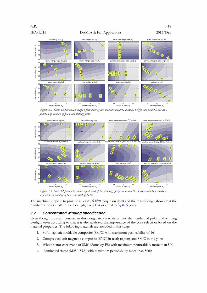
2.2 Concentrated winding specification Even though the main concern in this design step is to determine the number of poles and winding configuration according to that it is also analyzed the importance of the core selection based on the material properties. The following materials are included in this stage
1. Soft magnetic moldable composite (SM2C) with maximum permeability of 16
2. Compressed soft magnetic composite (SMC) in teeth regions and SM2C in the yoke
3. Whole stator core made of SMC (Somaloy-P5) with maximum permeability more than 500
4. Laminated stator (M250-35A) with maximum permeability more than 5000
A.R. 6-18
IEA/LTH DAMIA-2: Fan Applications 2013/Dec
The calculation (Figure 2.4), which is carried out in 2D FEA, where the field controlled machine is modeled, estimates the average torque, the torque ripple and the corresponding losses in the stator. The power losses in the windings are presented as a load torque at 900 rpm and the power losses in the core are at 9000 rpm [1]. The different speeds are selected in order to make the power losses more distinguishable as additional “internal load torque”.
Figure 2.4 Average torque, ripple and losses as a drag torque over speed of four different stator of the Long & Slender machine.
From this analysis it is clear that the electrical machines with SM2C cores need to provide extremely inexpensive production that they remain to be attractive with their specific low torque capability compared to the other cores and solutions. It seems that SM2C machines can be more efficient at higher frequency and speed but still higher permeability couples more high frequency field that low permeability material is not able to attract (Figure 2.4). High frequency leakage field can easily produce power losses in the other structures and the whole solution is not as efficient anymore.
From this study it is clear that the machine has to be specified either as 20-pole and 18-coil or 16-pole and 18-coil.
A.R. 7-18
IEA/LTH DAMIA-2: Fan Applications 2013/Dec
2.3 Comparison between wave-winding and distributed concentrated winding From manufacturability point of view the wave-windings have caught a lot of attention as during the project (Damia-2) there are number of successful results produced that has to be included in return into the machine design process. By starting from the round wire to profiled rectangular and even further to the planar sheet of the conductor, the various production methods based on deforming 1) a solenoid or 2) a single wire, or alternatively 3) gutting all segments of planar sheets or 4) cutting and rolling it together gives a variety of options for the production [2]-[4].
From magnetic construction (or concern) point of view, the wave-winding looks like a remarkable improvement of a simple planar solenoid in a transversal flux machine, which has the main field direction in the axial direction and thanks to the high permeability core it is modulated towards an air-gap that makes it as a transversal axial flux machine or transversal radial flux machine. On the contrary the wave-winding can be seen as a badly unbalanced coil when comparing to the modular winding. Some concern that is obvious with this kind of (transversal) machines
1. Cogging – usually there is same amount of excitation poles as the stator poles that makes the filed alternation possible. High number of poles may result more to the cogging than to the coupling
2. Power factor – is the problem for all transversal flux machines and becomes more in evidence with reduced of permeability in the core.
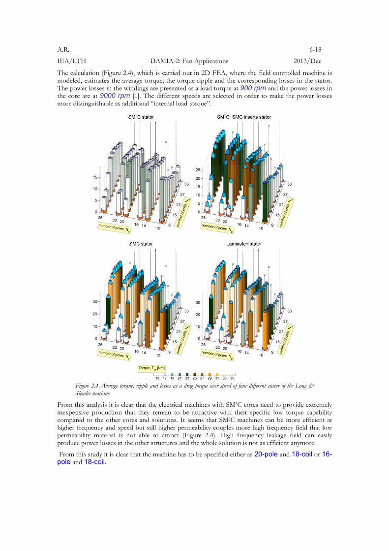
Nevertheless of the magnetic concern, a perfect sample of segment molding with a good pole formation is experimentally tested and evaluated [2]. Based on this production achievement for a simpler machine construction an extensive effort of 3D FE simulations are processed in order to show the potential of the topology and the risks related to material selection. 2D FE optimization routine is used to predefine the 3D FE geometry.
+A
77.50 87.5050.00
air Am1 Br=1.11TAc1 1117 SteelBc1 30-0.75-1.50Bi1 Bw 1 Jm=5.00A/mm2
ext
0.3
0.4
0.5
0.6
slot
ting
fact
or, K
s [-]
f lux linkage, m [Vs]
0.00
3
0.003
0.00
35
0.0035
0.00
4
0.0045
flux density, Bth [T]
0.9 1 1.1
f lux density, Byk [T]
0.220.240.26
0.28
0.28
0.3
0.3
0.32
0.34
10 30 100 300 10000.3
0.4
0.5
0.6
relative permeability, [-]
slot
ting
fact
or, K
s [-]
average torque, T [Nm]
2
2 3
3
4
4
5
5
6
6
7
7
10 30 100 300 1000
relative permeability, [-]
torque ripple, P [Nm]
4
6 8
10
10
12
12
14
14
16
16
18
18
10 30 100 300 1000
relative permeability, [-]
height of end turn, he [m]
0.006
0.008
0.01
0.012
0.014
0.016
Figure 2.5 2D FE simulations used to provide optimal dimension for the winding and consider also the magnetic permeability of the core.
Figure 2.5 shows the interesting character for the magnetic core, where the magnetic permeability determines the braking point when the core looses extensively the ability to carry the field and to couple the machine parts magnetically. For this geometry and material specifications the relative magnetic permeability of the core has to be more than 30 so that the permeability of the air-gap becomes more dominant and the flux is less influenced by the permeability of the core.
Figure 2.5 is used do determine whether the coil or the stator tooth has parallel sides and constant width. By considering the same cross sectional area in the slots and in the end turns, the overhang of the trapezoidal shaped winding area is larger than for the rectangular shaped winding area. The target designs of 1) the rectangular coil area axially stacked wave-winding, 2) the trapezoidal coil area axially stacked wave-winding, and 3) distributed concentrated winding are shown .
A.R. 8-18
IEA/LTH DAMIA-2: Fan Applications 2013/Dec
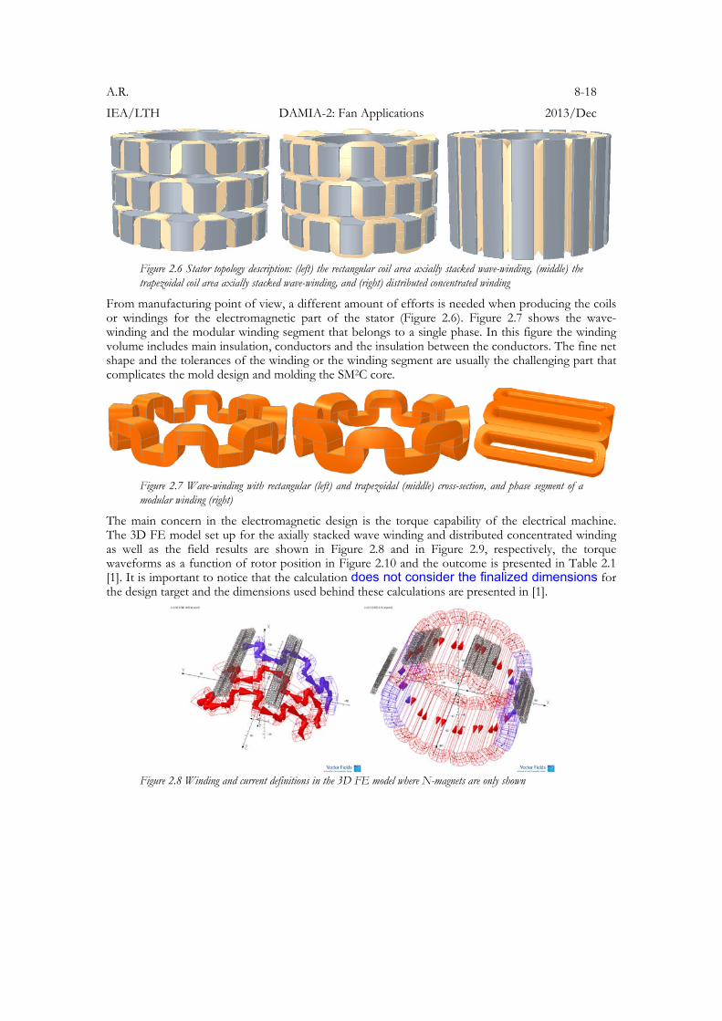
Figure 2.6 Stator topology description: (left) the rectangular coil area axially stacked wave-winding, (middle) the trapezoidal coil area axially stacked wave-winding, and (right) distributed concentrated winding
From manufacturing point of view, a different amount of efforts is needed when producing the coils or windings for the electromagnetic part of the stator (Figure 2.6). Figure 2.7 shows the wave-winding and the modular winding segment that belongs to a single phase. In this figure the winding volume includes main insulation, conductors and the insulation between the conductors. The fine net shape and the tolerances of the winding or the winding segment are usually the challenging part that complicates the mold design and molding the SM2C core.
Figure 2.7 Wave-winding with rectangular (left) and trapezoidal (middle) cross-section, and phase segment of a modular winding (right)
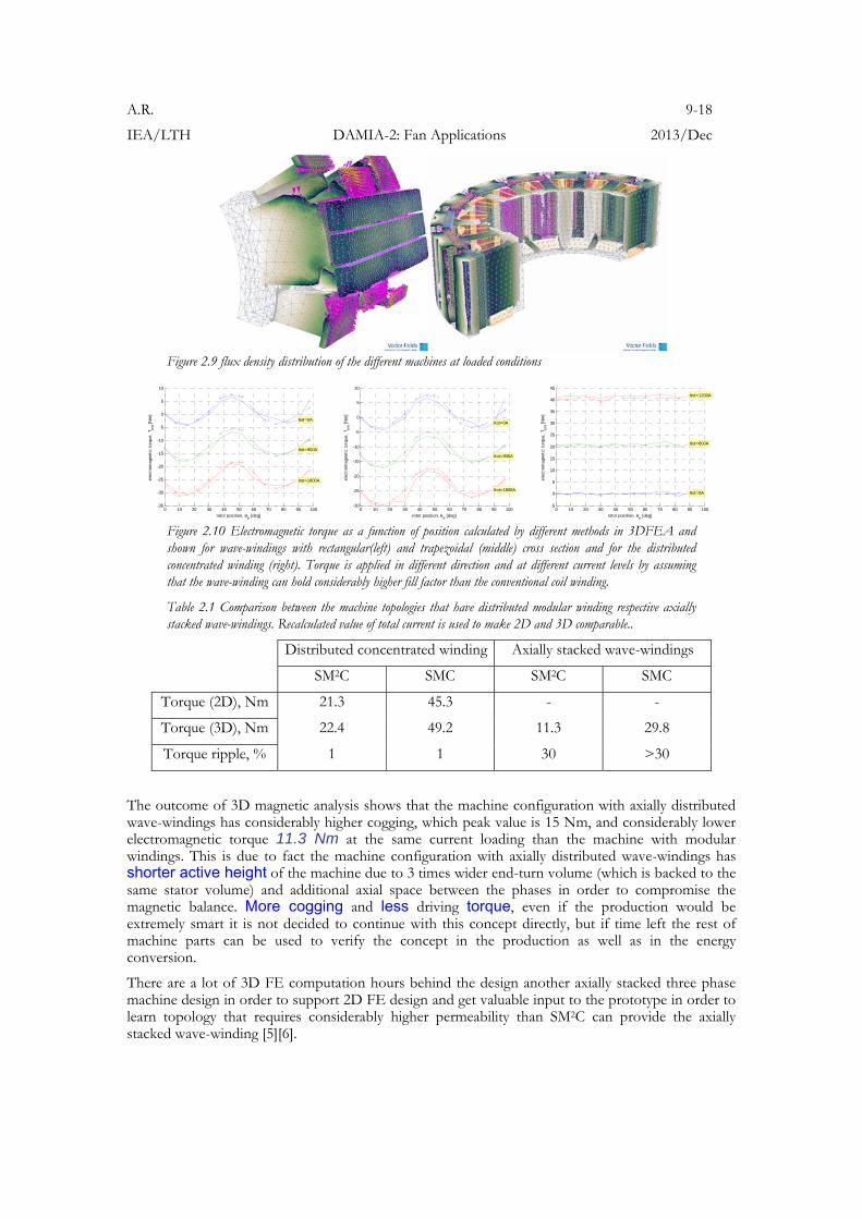
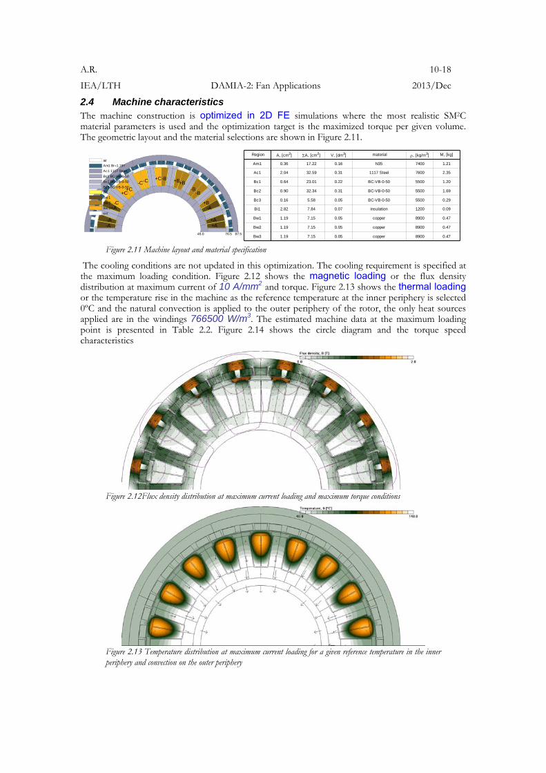
The main concern in the electromagnetic design is the torque capability of the electrical machine. The 3D FE model set up for the axially stacked wave winding and distributed concentrated winding as well as the field results are shown in Figure 2.8 and in Figure 2.9, respectively, the torque waveforms as a function of rotor position in Figure 2.10 and the outcome is presented in Table 2.1 [1]. It is important to notice that the calculation does not consider the finalized dimensions for the design target and the dimensions used behind these calculations are presented in [1].
Figure 2.8 Winding and current definitions in the 3D FE model where N-magnets are only shown
A.R. 9-18
IEA/LTH DAMIA-2: Fan Applications 2013/Dec
Figure 2.9 flux density distribution of the different machines at loaded conditions
0 10 20 30 40 50 60 70 80 90 100-35
-30
-25
-20
-15
-10
-5
0
5
10
Itot=0A
Itot=900A
Itot=1800A
rotor position, e [deg]
elec
trom
agne
tic t
orqu
e, T
em [
Nm
]
0 10 20 30 40 50 60 70 80 90 100
-30
-25
-20
-15
-10
-5
0
5
10
Itot=0A
Itot=900A
Itot=1800A
rotor position, e [deg]
elec
trom
agne
tic t
orqu
e, T
em [
Nm
]
0 10 20 30 40 50 60 70 80 90 100
-5
0
5
10
15
20
25
30
35
40
45
Itot=0A
Itot=600A
Itot=1200A
rotor position, e [deg]
elec
trom
agne
tic t
orqu
e, T
em [
Nm
]
Figure 2.10 Electromagnetic torque as a function of position calculated by different methods in 3DFEA and shown for wave-windings with rectangular(left) and trapezoidal (middle) cross section and for the distributed concentrated winding (right). Torque is applied in different direction and at different current levels by assuming that the wave-winding can hold considerably higher fill factor than the conventional coil winding.
Table 2.1 Comparison between the machine topologies that have distributed modular winding respective axially stacked wave-windings. Recalculated value of total current is used to make 2D and 3D comparable..
Distributed concentrated winding Axially stacked wave-windings
SM2C SMC SM2C SMC
Torque (2D), Nm 21.3 45.3 - -
Torque (3D), Nm 22.4 49.2 11.3 29.8
Torque ripple, % 1 1 30 >30
The outcome of 3D magnetic analysis shows that the machine configuration with axially distributed wave-windings has considerably higher cogging, which peak value is 15 Nm, and considerably lower electromagnetic torque 11.3 Nm at the same current loading than the machine with modular windings. This is due to fact the machine configuration with axially distributed wave-windings has shorter active height of the machine due to 3 times wider end-turn volume (which is backed to the same stator volume) and additional axial space between the phases in order to compromise the magnetic balance. More cogging and less driving torque, even if the production would be extremely smart it is not decided to continue with this concept directly, but if time left the rest of machine parts can be used to verify the concept in the production as well as in the energy conversion.
There are a lot of 3D FE computation hours behind the design another axially stacked three phase machine design in order to support 2D FE design and get valuable input to the prototype in order to learn topology that requires considerably higher permeability than SM2C can provide the axially stacked wave-winding [5][6].
A.R. 10-18
IEA/LTH DAMIA-2: Fan Applications 2013/Dec
2.4 Machine characteristics The machine construction is optimized in 2D FE simulations where the most realistic SM2C material parameters is used and the optimization target is the maximized torque per given volume. The geometric layout and the material selections are shown in Figure 2.11.
+A+A
-A+B
-B-B
+B+B-B+C-C-C+C
+C
-C+A
-A-A
76.5 87.545.0
air
Am1 Br=1.19T
Ac1 1117 Steel
Bc1 BC-VB-0-50
Bc2 BC-VB-0-50
Bc3 BC-VB-0-50
Bi1
Bw 1
Bw 2
Bw 3
ext
Region A, [cm2] A, [cm2] V, [dm3] material , [kg/m3] M, [kg]
Bw3 1.19 7.15 0.05 copper 8900 0.47
Bw2 1.19 7.15 0.05 copper 8900 0.47
Bw1 1.19 7.15 0.05 copper 8900 0.47
Bi1 2.82 7.84 0.07 insulation 1200 0.09
Bc3 0.16 5.58 0.05 BC-VB-0-50 5500 0.29
Bc2 0.90 32.34 0.31 BC-VB-0-50 5500 1.69
Bc1 0.64 23.01 0.22 BC-VB-0-50 5500 1.20
Ac1 2.04 32.59 0.31 1117 Steel 7600 2.35
Am1 0.36 17.22 0.16 N35 7400 1.21
Figure 2.11 Machine layout and material specification
The cooling conditions are not updated in this optimization. The cooling requirement is specified at the maximum loading condition. Figure 2.12 shows the magnetic loading or the flux density distribution at maximum current of 10 A/mm2 and torque. Figure 2.13 shows the thermal loading or the temperature rise in the machine as the reference temperature at the inner periphery is selected 0ºC and the natural convection is applied to the outer periphery of the rotor, the only heat sources applied are in the windings 766500 W/m3. The estimated machine data at the maximum loading point is presented in Table 2.2. Figure 2.14 shows the circle diagram and the torque speed characteristics
Figure 2.12Flux density distribution at maximum current loading and maximum torque conditions
Figure 2.13 Temperature distribution at maximum current loading for a given reference temperature in the inner periphery and convection on the outer periphery
A.R. 11-18
IEA/LTH DAMIA-2: Fan Applications 2013/Dec
Table 2.2 Estimated machine data
outer heat transfer hao 3.9 W/Km2 acceleration current Iacc 22.0 A
inner heat transfer hai 92.8 W/Km2 cranking torque Tcr NaN Nm
outer cooling Qao 259.4 W/m2 acceleration torque Tacc 30.2 Nm
inner cooling Qai 11294.3 W/m2 saliency ratio 0.9 -
outer surface temp out 56.2 C core loss @ nmax Pfem NaN W
inner surface temp in 1.2 C max speed @ 0.9Pmax nmax 9.0 krpm
hot-spot temperetaure max 122.9 C load angle 16.9 deg
dc link voltage Udc 600.0 V cogging torque T 2.7 Nm
base speed no 6.0 krpm torque ripple T 2.8 Nm
flux linkage Psimo 3.5 mVs specific cost cost/M 285.4 kr/kg
total current NIm 1.4 kAturn estimated material cost cost 2328.2 kr
current density Jcm 10.0 A/mm2 specific power P/V 2327.3 W/m3
yoke flux density Bym 302.6 mT specific torque T/M 3.7 Nm/kg
teeth flux density Btm 1.2 T magnetic shear stress MSS 8659.6 N/cm2
winding fill factor Kf 0.6 - estimated efficiency 97.9 %
total weight Mtot 8.2 kg nominal power Pout 19.0 kW
weight of rotor Mrt 3.6 kg rotor losses Prt 3.6 W
weight of stator Mst 4.6 kg core losses Pfe 24.5 W
weight of rotor magnet Mrtpm 1.2 kg copper losses Pcu 380.0 W
weight of stator winding Mstcu 1.4 kg moment of inertia J 26.3 gm/s2
weight of stator core Mstfe 3.2 kg nominal torque T 30.2 Nm
number of slots Ns 18.0 - quadrature inductance Lsy 913.2 H
number of poles Np 16.0 - direct inductance Lsx 838.3 H
air-gap length g 1.0 mm resistance Rs 65.6 mOhm
actual length ltot 119.8 mm rms back emf E 289.6 V
active length lact 95.0 mm rms phase voltage U 300.0 V
inner radius ri 45.0 mm rms phase current I 22.0 A
outer radius ro 87.5 mm number of turns Nt 23.0 turns
quantity symbol value unit quantity symbol value unit
A.R. 12-18
IEA/LTH DAMIA-2: Fan Applications 2013/Dec
-35 -30 -25 -20 -15 -10 -5 00
5
10
15
20
25
30
35
360
380
380
400
400
400
420
420
420
440
440
440
460
460
460
480
480
480
500
500
500
520
520
520
540
Us [V] @ n=6.0 krpm
Tem [Nm]
5 5
10 10
15 15
20 20
25 25
30 30
magnetising current, Isx
[A]
acce
lera
ting
curr
ent,
I sy [
A]
0 1 2 3 4 5 6 7 8 90
5
10
15
20
25
30
Ismax
[A]
4
7
11
15
18
22
26
29
3336
speed, n [krpm]el
ectr
omag
netic
tor
que,
Tem
[N
m]
0 1 2 3 4 5 6 7 8 90
2
4
6
8
10
12
14
16
18
elec
trom
agne
tic p
ower
, P
em [
kW]
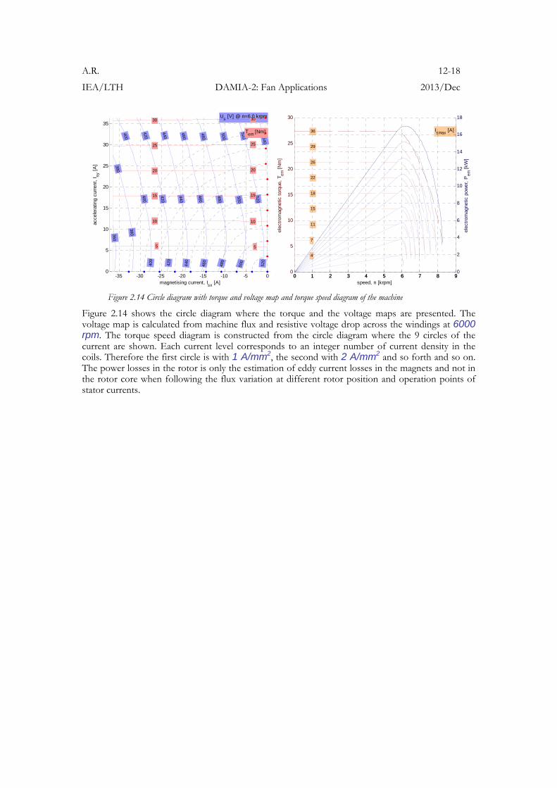
Figure 2.14 Circle diagram with torque and voltage map and torque speed diagram of the machine
Figure 2.14 shows the circle diagram where the torque and the voltage maps are presented. The voltage map is calculated from machine flux and resistive voltage drop across the windings at 6000 rpm. The torque speed diagram is constructed from the circle diagram where the 9 circles of the current are shown. Each current level corresponds to an integer number of current density in the coils. Therefore the first circle is with 1 A/mm2, the second with 2 A/mm2 and so forth and so on. The power losses in the rotor is only the estimation of eddy current losses in the magnets and not in the rotor core when following the flux variation at different rotor position and operation points of stator currents.
A.R. 13-18
IEA/LTH DAMIA-2: Fan Applications 2013/Dec
3 Manufacturing and assembling process The earlier efforts on molding SM2C core around the windings have established some concern that directly influenced the manufacturing the prototype. By inspired of the good design and manufacturing experience, which should be repeated, there are a number of “small obstacles” that should get more attention before the new prototype is processed. By taking the manufacturing in prior to design, which is for the sake of the goal to provide a good design for manufacturability and likely not the best design for the performance, there is a tree of events to be considered:
1. Ideally the stator core is molded i.e. assembled in a single process step. In practice it is always optimized towards that. The rotocast molding is preferred to (low pressure) injection molding so that the better and more compact core can be achieved, not least the change of relative permeability around 11 to 16 when comparing injection molding to the rotocast molding,
2. In order to achieve single step molding the mould and the components in the mold such as coils, pieces of higher permeability core, insulation, mechanical support or/and cooling system, etc have to be carefully designed and manufactured. If this condition is not fulfilled then either the molding process fails – there is no homogeneous core inside all the intentional cavities of the stator, or the machine performance is reduced due to various failures
o Geometrical tolerances: insufficient tolerances cause failure in montage, 1) insufficient fill rate in tooth-tips, teeth etc, or 2) incorrect fill in the gaps and gravities where should not to be any core, but where the core material enters during molding. Typical concern here is geometrically well defined coils and windings. This task gets even harder when high fill factor is desired in order to compensate somehow the low permeability of the SM2C core.
o Introduction of new concepts such as establishing main insulation system by 1) tipping the coils or windings or even 2) extra molding of the dielectric insulation. This causes directly the final component tolerances. The innovative process comes together with uncertainty, which cause failures in the dielectric system.
o Geometric or geometry alteration due to various process related loads. Understandable example here is that the component in the mold may move due to the forces applied in the molding process or the dimensions of the mold can change due to temperature. There are number of aspects that influence the molding process and the outcome of the process. The outcome of these aspects can lead to increased complexity such as it can result more components into the mould, such as fixation structures, and also splitting the single step process to a few processes.
o Mechanical and electrical termination is usually not as vital in practice as it could be imagined, neglected and solved later
3. The disassembling process has to be considered too when designing the mold
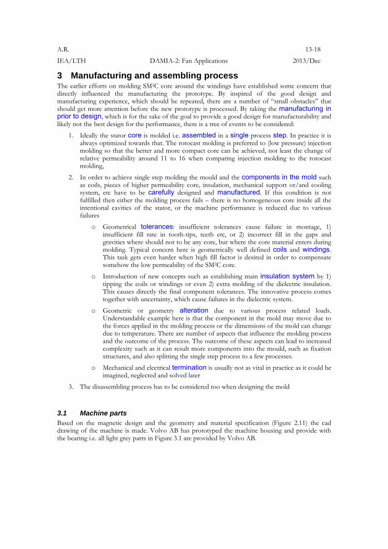
3.1 Machine parts Based on the magnetic design and the geometry and material specification (Figure 2.11) the cad drawing of the machine is made. Volvo AB has prototyped the machine housing and provide with the bearing i.e. all light grey parts in Figure 3.1 are provided by Volvo AB.
A.R. 14-18
IEA/LTH DAMIA-2: Fan Applications 2013/Dec
Figure 3.1 CAD drawing of the prototype target
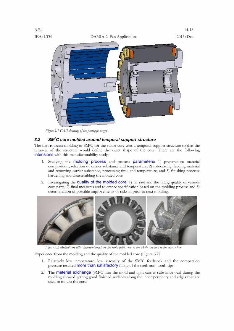
3.2 SM2C core molded around temporal support structure The first rotocast molding of SM2C for the stator core uses a temporal support structure so that the removal of the structure would define the exact shape of the core. There are the following intensions with this manufacturability study:
1. Studying the molding process and process parameters: 1) preparation: material composition, selection of carrier substance and temperature, 2) rotocasting: feeding material and removing carrier substance, processing time and temperature, and 3) finishing process: hardening and disassembling the molded core
2. Investigating the quality of the molded core: 1) fill rate and the filling quality of various core parts, 2) final measures and tolerance specification based on the molding process and 3) determination of possible improvements or risks in prior to next molding.
Figure 3.2 Molded core after disassembling from the mold (left), view to the whole core and to the core section
Experience from the molding and the quality of the molded core (Figure 3.2)
1. Relatively low temperature, low viscosity of the SM2C feedstock and the compaction pressure resulted more than satisfactory filling of the teeth and tooth-tips
2. The material exchange (SM2C into the mold and light carrier substance out) during the molding allowed getting good finished surfaces along the inner periphery and edges that are used to mount the core.
A.R. 15-18
IEA/LTH DAMIA-2: Fan Applications 2013/Dec
3.3 SM2C core molded around the main insulation system The next molding is processed on the verifications from the pre previous experience. Figure 3.3 shows the main insulation system in the mold, the exchange process where the more dense iron settles, air backs away and also the carrier substance collects to the uppermost part of the mold. The finished product from the top and the side is shown in Figure 3.3. The manufacturing tolerances of the mold are not perfect so that the insulation system is not clearly seen between the tooth-tips.
Figure 3.3 The mould with the main insulation system (left), the exchange process (left from the middle) and the ready stator from top and side view
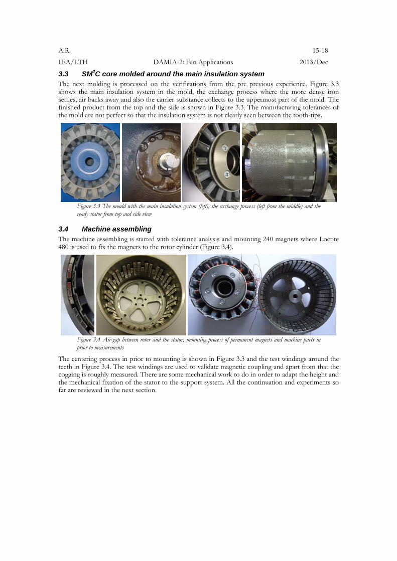
3.4 Machine assembling The machine assembling is started with tolerance analysis and mounting 240 magnets where Loctite 480 is used to fix the magnets to the rotor cylinder (Figure 3.4).
Figure 3.4 Air-gap between rotor and the stator, mounting process of permanent magnets and machine parts in prior to measurements
The centering process in prior to mounting is shown in Figure 3.3 and the test windings around the teeth in Figure 3.4. The test windings are used to validate magnetic coupling and apart from that the cogging is roughly measured. There are some mechanical work to do in order to adapt the height and the mechanical fixation of the stator to the support system. All the continuation and experiments so far are reviewed in the next section.
A.R. 16-18
IEA/LTH DAMIA-2: Fan Applications 2013/Dec
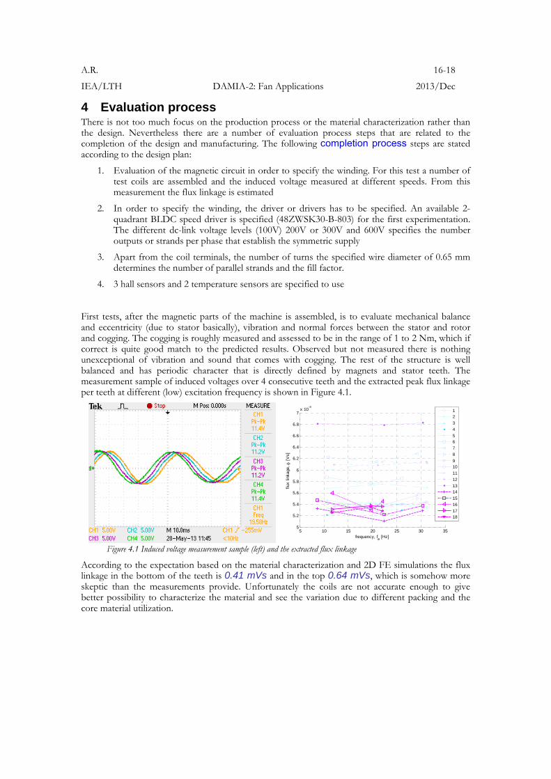
4 Evaluation process There is not too much focus on the production process or the material characterization rather than the design. Nevertheless there are a number of evaluation process steps that are related to the completion of the design and manufacturing. The following completion process steps are stated according to the design plan:
1. Evaluation of the magnetic circuit in order to specify the winding. For this test a number of test coils are assembled and the induced voltage measured at different speeds. From this measurement the flux linkage is estimated
2. In order to specify the winding, the driver or drivers has to be specified. An available 2-quadrant BLDC speed driver is specified (48ZWSK30-B-803) for the first experimentation. The different dc-link voltage levels (100V) 200V or 300V and 600V specifies the number outputs or strands per phase that establish the symmetric supply
3. Apart from the coil terminals, the number of turns the specified wire diameter of 0.65 mm determines the number of parallel strands and the fill factor.
4. 3 hall sensors and 2 temperature sensors are specified to use
First tests, after the magnetic parts of the machine is assembled, is to evaluate mechanical balance and eccentricity (due to stator basically), vibration and normal forces between the stator and rotor and cogging. The cogging is roughly measured and assessed to be in the range of 1 to 2 Nm, which if correct is quite good match to the predicted results. Observed but not measured there is nothing unexceptional of vibration and sound that comes with cogging. The rest of the structure is well balanced and has periodic character that is directly defined by magnets and stator teeth. The measurement sample of induced voltages over 4 consecutive teeth and the extracted peak flux linkage per teeth at different (low) excitation frequency is shown in Figure 4.1.
5 10 15 20 25 30 355
5.2
5.4
5.6
5.8
6
6.2
6.4
6.6
6.8
7x 10
-3
frequency, fe [Hz]
flux
linka
ge,
[V
s]
12
3
4
56
7
8
910
11
12
1314
15
16
1718
Figure 4.1 Induced voltage measurement sample (left) and the extracted flux linkage
According to the expectation based on the material characterization and 2D FE simulations the flux linkage in the bottom of the teeth is 0.41 mVs and in the top 0.64 mVs, which is somehow more skeptic than the measurements provide. Unfortunately the coils are not accurate enough to give better possibility to characterize the material and see the variation due to different packing and the core material utilization.
A.R. 17-18
IEA/LTH DAMIA-2: Fan Applications 2013/Dec
5 Conclusions and future work The ultimate goal of this work in Damia-2 has not reached to the end as the drive unit is not completed but the essential goal is accomplished. The central goal of this work is achieved as
1. Stator core with rotomoulded SM2C is built and the crucial parameters such as 1) flux linkage, 2) cogging torque and 3) not least the manufacturing process is experimentally verified
2. The new unconventional way of building machine core – innovative but not rational has the focus on the main insulation system. This is important contribution to this project as the insulation system may have lack of attention when having focus on a number of other vital issues. The shell of the insulation system is placed into the mould and the soft moldable composite is feed into the mould and rotocasted into the cavities of the insulation system where the core has to be. The other cavities for the winding are leak free due to a proper tightening.
3. For the case of manufacturability, this prototyped stator shows the new level of geometric complexity with good results as 1) the tooth-tips were properly filled, and 2) the molding process gave fine finished surfaces as there is a special concern of replacing the carrier substance with iron powder so that there is minimum overflow of the carrier substance and maximized utilization of the iron content for this low pressure compaction process used. The challenge is the hand made windings.
4. For the case of electromagnetic design, there are not too many choices left to compensate the drastic reduction of magnetic permeability when turning a conventional core to a molded core. Usually the reduction of air-gap and improving the winding, taking advantage of embedded coils in order to reduce the overhangs or increase the active axial height Hact has small effect against the overall reduction of torque capability. If the machine construction takes advantage of core-less principle or if the magnetic core obviously suffers under the high core losses then the soft magnetic moldable composite could probably be a good alternative.
5. The essential part of this project is related to manufacturability for design, where usually the simple arrangement for production does not establish a good design for electromechanical energy conversion. The originality of this (Damia-2) project is the reversed order for the electrical machine production, where the windings with insulation comes first and moulding is used as an assembling process to compile the pieces into a mold into a single piece, brings up many new ideas, establishes a broad basis of design and manufacturing experience.
6. The design and manufacturing of the high speed brushless PMSM for fan application, prevents previous manufacturing complications and tries to get the best out from the SM2C material, but likely not for overall efficient production process or/and for the most energy/volume efficient solution for the application.
The future work is 1) to complete the winding for the specified driver and 2) to verify the machine performance.
A.R. 18-18
IEA/LTH DAMIA-2: Fan Applications 2013/Dec
References Self references related to research
[1] Reinap, A., Alaküla, M. (2012), “Impact of soft magnetic material on construction of radial flux electrical machines”. IEEE Transactions on Magnetics, vol. 48, no. 4, pp. 1613-1616.
[2] Reinap, A., Hagstedt, D., Högmark, C., Alaküla, M. (2011), “Evaluation of a Semi Claw-Pole Machine with SM2C Core”. International Electrical Machines and Drives Conference (IEMDC2011), Niagara Falls, Ontario, Canada, May 15-18, 2011
[3] Högmark, C., Reinap, A., Frogner, K., Alaküla, M. (2012), “Laminated winding with rapid cooling capability for electrical machines”. International Conference for Inductive and Electromagnetic Components, Systems and Devices including Manufacturing and Processing (INDUCTICA 2012), Berlin, Germany, June 26-28, 2012.
[4] Svensson, L., Frogner, K., Reinap, A., Högmark, C., Andersson, M., Alaküla, M. (2012), “Alternative production process for electric machine windings”. International Electric Drives Production Conference and Exhibition (EDPC2012), Nuremberg, Germany, Oct. 16-17, 2012.
[5] Högmark, C., Andersson, R., Reinap, A., Alaküla, M. (2012), “Electrical Machines with Laminated Winding for Hybrid Vehicle Applications”. International Electric Drives Production Conference and Exhibition (EDPC2012), Nuremberg, Germany, Oct. 16-17, 2012.
[6] Andersson, R., Högmark, C., Reinap, A., Alaküla, M. (2012), “Modular Three-phase Machines with Laminated Winding for Hybrid Vehicle Applications”. International Electric Drives Production Conference and Exhibition (EDPC2012), Nuremberg, Germany, Oct. 16-17, 2012.