Embed Size (px)
Citation preview

HIGH SPEED 8-BIT EMBEDDED MICROCONTROLLER
Final Project Report
Presented To
Dr. Leonard P. Wesley
MSE
San Jose State University
In Partial Fulfillment
Of the Requirement for ENGR 298
By Group 5
Hardik Thakkar Neha Razdan Nikita Patel
April, 2009

Final Project Report for ENGR298 Spring 2009
2
© 2009
Neha Razdan
Nikita Patel
Hardik Thakkar
ALL RIGHTS RESERVED
Final Project Report for ENGR298 Spring 2009
3
APPROVAL PAGE
Approved by
Supervising Committee:
_________________________
Professor Morris Jones
Instructor of Electrical Engineering
San Jose State University
_________________________
Dr. Peter Reischl
Professor of Electrical Engineering
San Jose State University.
________________________
Dr. Leonard Wesley
Associate Professor of Computer
Engineering
San Jose State University

Final Project Report for ENGR298 Spring 2009
4
ABSTRACT
The numbers of transistors on the chip are increasing and the chip size is decreasing
every 18 months following Moore's law. The main focus of the Start up Semiconductor
Company is to increase speed and reduce area of 8 bit Embedded Microcontroller chip.
The company plans to create a product to achieve a maximum frequency of around 1.5
GHz. The hardware design of this Microcontroller covers less area on the chip and is free
from any software related routing problems. Also the customers have been provided the
flexibility of programming the Embedded Microcontroller according to the required
application. The cost of this Microcontroller is comparatively less than the existing
Microcontrollers in the market. The proposed design is not only a technological marvel
but also a cost efficient solution for our customers.
Final Project Report for ENGR298 Spring 2009
5
ACKNOWLEDGEMENT
We would like to sincerely thank and express our deep gratitude to Mr. Morris Jones,
Dept. of Electrical Engineering, San Jose State University, for his thorough guidance and
valuable suggestions throughout the course of this project.
Similarly our gratitude extends to Dr.Peter Reischl, Dept. of Electrical
Engineering, San Jose State University, who helped to shape our strategy and helped to
overcome the difficulties we faced during the execution of this project.
Dr. Leonard P. Wesley, Associate Professor, Dept. of Computer Engineering,
San Jose State University, deserves our sincere thanks as without him it would not have
been possible for us to achieve the objectives of this project.
- Neha Razdan
- Nikita Patel
- Hardik Thakkar
Final Project Report for ENGR298 Spring 2009
6
TABLE OF CONTENTS
1. Introduction..................................................................................................................... 9 2. Project Preliminary Scope............................................................................................ 10 2.1 Hypothesis................................................................................................................... 10 2.2 Method of Investigation.............................................................................................. 10 2.3 Resource Utilization.................................................................................................... 10 2.4 Process Technology .................................................................................................... 11 2.5 Product Specification .................................................................................................. 11 2.6 Experimental Procedure.............................................................................................. 12 3. Literature Survey on Microcontroller .......................................................................... 14 3.1 Basic Processor ........................................................................................................... 14 3.2 Basic Microcontroller ................................................................................................. 15 3.3 Difference between Microcontroller and Microprocessor.......................................... 16 3.4 Why 8 bit Microcontroller .......................................................................................... 17 3.5 Embedded Microcontroller ......................................................................................... 18 3.6 Applications of Embedded Microcontrollers.............................................................. 18 3.7 Pico Blaze 8-bit Embedded Microcontroller .............................................................. 19 3.8 Reference Block Diagram for Design......................................................................... 20 4. Design of Pico Blaze 8- Bit Microcontroller .............................................................. 22 4.1 Multiplexers ................................................................................................................ 22 4.2 Register File ................................................................................................................ 23 4.3 SRAM (Static Random Access Memory)................................................................... 25 4.4 Instruction PROM (Programmable Read Only Memory)........................................... 26 4.5 Program Counter......................................................................................................... 27 4.6 Stack Pointer ............................................................................................................... 29 4.7 Instruction Decoder..................................................................................................... 30 4.8 ALU (Arithmetic Logic Unit)..................................................................................... 34 4.9 Zero/Carry Flag........................................................................................................... 36 4.10 Interrupt..................................................................................................................... 37 4.11 Input and Output ....................................................................................................... 38 4.12 Interfacing of Top level Blocks ................................................................................ 38 4.13 Pipelining of 8-bit Embedded Microcontroller......................................................... 39 4.14 Testing and simulation Results ................................................................................. 42
4.14.1 Testing of R-type (Register-type) instruction ................................................ 43 4.14.2 Testing of Branch Instruction ........................................................................ 44 4.14.3 Final Testing of the whole program............................................................... 45
4.15 Applications of 8-bit Embedded Microcontroller..................................................... 46 4.16 Future Expansion of 8 bit Embedded Microcontroller ............................................. 48 5. Economic Justification.................................................................................................. 49 5.1 Executive Summary .................................................................................................... 49 5.2 Problem Statement ...................................................................................................... 50 5.4 Established Companies in Microcontroller Business ................................................. 52 5.5 Customer ..................................................................................................................... 52 5.6 Market Size of 8 bit Embedded Microcontroller ........................................................ 53
5.6.1 Consumer Electronics ...................................................................................... 54
Final Project Report for ENGR298 Spring 2009
7
5.6.2 Automotive Industrial Applications................................................................. 55 5.7 Costs............................................................................................................................ 55 5.8 Price Point................................................................................................................... 58 5.9 SWOT Assessment ..................................................................................................... 59 5.10 Investment Capital Requirement............................................................................... 59 5.11 Personnel................................................................................................................... 60 5.12 Businesses and Revenue Model................................................................................ 61 5.13 Break Even Analysis................................................................................................. 63 5.14 Strategic Alliance /Partner ........................................................................................ 66 5.15 Profit and Loss Statement ......................................................................................... 66 5.16 Exit Strategies ........................................................................................................... 67 5.17 Norden Rayleigh Profile ........................................................................................... 68 5.18 Future of 8-Bit Embedded Microcontroller .............................................................. 71 Conclusion ........................................................................................................................ 73 REFERENCES ................................................................................................................. 80
LIST OF TABLES: Table 1 Historical Development of Intel Microcontrollers............................................... 15 Table 2 Pros and Cons of Pico Blaze Microcontroller ..................................................... 20 Table 3 Logic of a 2to1 mux............................................................................................. 22 Table 4 Program for executing JUMP and LOAD instructions........................................ 27 Table 5 Test Case for R- type Instructions ....................................................................... 43 Table 6 Test case for Branch Instruction .......................................................................... 45 Table 7 Program for the Final Testing, Test case1 ........................................................... 45 Table 8 Program for the Final Testing, Test case2 ........................................................... 46 Table 9 Major Segments of Microcontroller Customers .................................................. 55 Table 10 Cost Distribution of 8-bit Embedded Microcontroller ...................................... 56 Table 11 Amount spent on Materials, Labor and Rent..................................................... 57 Table 12 SWOT Assessment ............................................................................................ 59 Table 13 Cash balance from year 2008 to 2012 ............................................................... 60 Table 14 Personnel required for 8-bit Embedded Microcontroller................................... 61 Table 15 Revenue from 2008 Q-4 to 2012 ....................................................................... 63 Table 16 Break Even Analysis.......................................................................................... 64
Final Project Report for ENGR298 Spring 2009
8
LIST OF FIGURES: Figure 1 Design Flow of 8-bit Embedded Microcontroller .............................................. 12 Figure 2 Comparison between Microprocessor and Microcontroller .............................. 17 Figure 3 Xilinx Pico Blaze 8-bit Embedded Microcontroller........................................... 20 Figure 4 Transistor level schematics of 2to1 mux ............................................................ 23 Figure 5 Schematics of a 4to16 decoder ........................................................................... 24 Figure 6 Schematics of 16 byte wide Register File .......................................................... 25 Figure 7 Test bench of SRAM.......................................................................................... 26 Figure 8 Test bench of PROM.......................................................................................... 27 Figure 9 Schematic of 10-bit Program Counter................................................................ 28 Figure 10 Schematic Diagram of 31 level Stack Pointer.................................................. 30 Figure 11 Schematic Diagram of Instruction Decoder ..................................................... 32 Figure 12 Schematic Diagram of PREDOCDER ............................................................. 33 Figure 13 Schematic Diagram of ROM............................................................................ 34 Figure 15 Schematics of 8-bit ALU.................................................................................. 36 Figure 16 Schematics of Zero Flag................................................................................... 37 Figure 17 Final Schematic of 8 bit microcontroller.......................................................... 39 Figure 18 Program being executed without Pipelining and with Pipelining ................... 40 Figure 19 Output of PROM with 2 instructions in pipeline.............................................. 41 Figure 20 Output of PROM with 3 instructions in pipeline.............................................. 42 Figure 21 Simulation Result of above program................................................................ 44 Figure 22 Revenue share for 8bit Embedded Microcontroller ......................................... 52 Figure 23 Division of total cost ........................................................................................ 57 Figure 24 Business and Revenue Model of 8-bit Embedded Microcontroller ................. 62 Figure 25 Graph showing Expense and Revenue ............................................................. 63 Figure 26 Break Even Analysis from Q42008 to Q3 2010............................................... 65 Figure 27 Break Even Analysis from Q4 2010 to Q4 2012.............................................. 65 Figure 28 Profit and Loss Profile...................................................................................... 67 Figure 29 Graph of Cumulative Distribution.................................................................... 69 Figure 30 Graph of Probability Density Function ............................................................ 70 Figure 31 Forecasting of 8-bit Microcontrollers in World Market till 2015 .................... 72
1. Introduction Microcontrollers are completely enclosed by the device they control like general purpose
PC; embedded systems. The Microcontroller applications vary from a simple Microwave
to Satellite systems. Higher clock speed (i.e. the number of instructions that can be
executed per second) will give rise to a more efficient Microcontroller. “Today’s system
designer has to work in highly competitive global market environment where they face
many challenges like improved product time to market, reduced Bill of Material (BOM)
cost and the most importantly to improve the functionality and performance. So to
overcome many design obstacles and accelerate system innovation, it is very important to
rapidly reconfigure the processor and its sub elements.” (Optimized for Performance
(November, 2006) [Embedded Magazine].Considering all the customer requirements, we
are providing a custom designed Hardcore 8-bit Embedded Microcontroller working at a
high speed of 1.5 GHz and consuming less chip area. The Product has a proven fast
production time resulting in reduced time to market, and will prove to be a Profitable
business. The targeted customers for 8-bit Embedded Microcontroller product are
Consumer Electronics Industry and Automotive Industry. This Microcontroller is almost
one third the cost of existing High speed microcontrollers in the market.
Final Project Report for ENGR298 Spring 2009
10
2. Project Preliminary Scope
2.1 Hypothesis In the wider Microprocessor market, Microcontroller takes the largest share of the market
sales. The demand for Microcontrollers has increased rapidly in the last couple of years.
Microcontrollers are every where in the world, from a small chip to the high profile
satellite system. The Company’s objective is to design an 8 bit embedded Microcontroller
for high speed applications, giving a cost effective solution to the customers.
2.2 Method of Investigation According to recent market survey, microcontrollers are used for various applications
like, USB, Ethernet, Nano watt technology, LCD and Motor Control. The main
requirement of microcontrollers in the present market is low cost, less area and higher
speed. The larger chip area results in a higher cost which limits the consumer demand.
2.3 Resource Utilization Design and Testing Tool: Cadence “Virtuoso” IC design Tool
Dynsize for Device size Calculation
Spectre Spice for simulation
Espresso logic reduction software
Process: IBM 0.13micron Technology
Operating System: UNIX
Final Project Report for ENGR298 Spring 2009
11
2.4 Process Technology The company uses Cadence Tool for the design. Although there are a couple of
technologies available in the Cadence library, but the company will use IBM0.13micron
technology for the design because it has some specific advantages over the other
technologies. Some of them are listed below.
1. Amount of metal used is less
2. Parasitic capacitance effect will be minimized as compared to IBM0.18micron
3. Fast production time
2.5 Product Specification The IP product of the company is 8bit microcontroller which provides flexible, high
performance, low cost and compact size solution to our customer. The 8 bit
microcontroller supports the following features.
16 Byte wide general purpose data register
1K instructions of programmable on-chip program store.
Byte-wide Arithmetic Logic Unit (ALU) with CARRY and ZERO indicator flags.
64-byte internal Scratchpad RAM
31-location CALL/RETURN stack
Fast Interrupt response
Predictable performance up to 1.5GHz
Final Project Report for ENGR298 Spring 2009
12
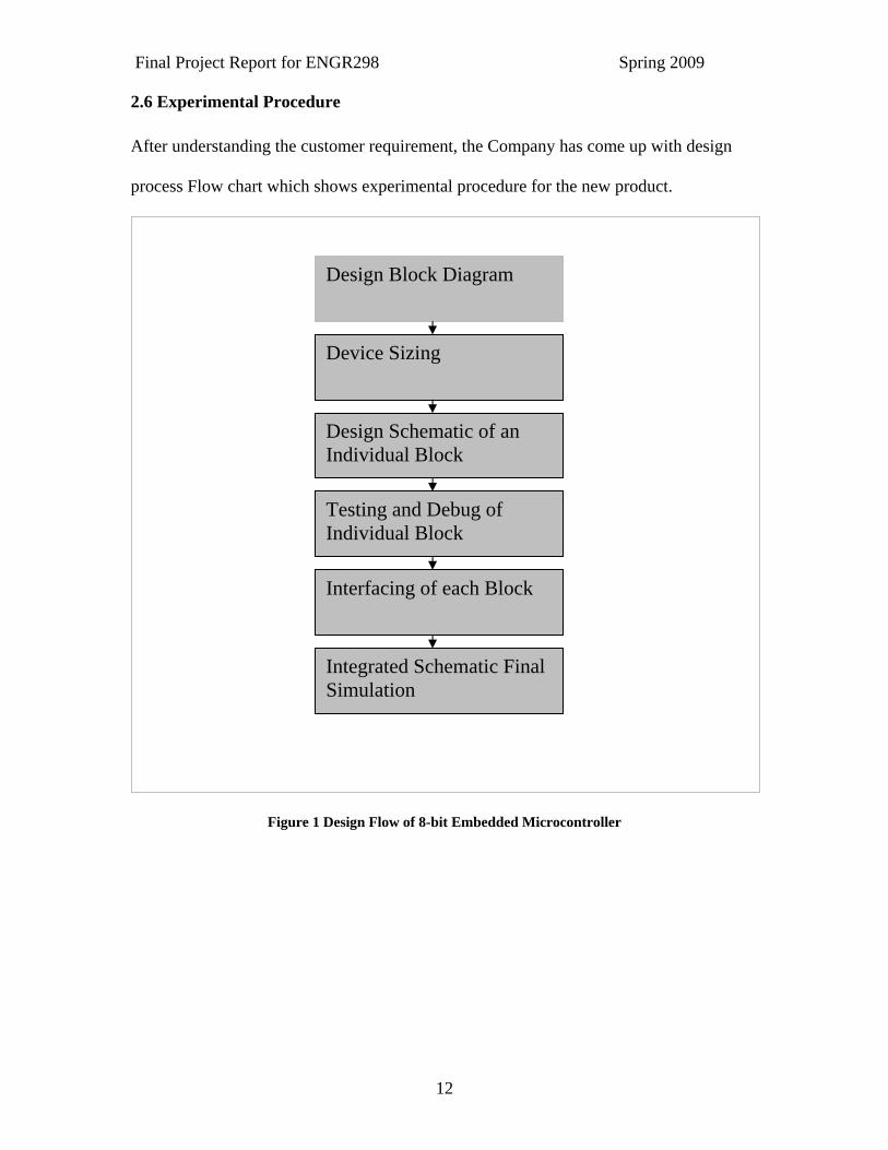
2.6 Experimental Procedure After understanding the customer requirement, the Company has come up with design
process Flow chart which shows experimental procedure for the new product.
Figure 1 Design Flow of 8-bit Embedded Microcontroller
Design Block Diagram
Device Sizing
Design Schematic of an Individual Block
Testing and Debug of Individual Block
Interfacing of each Block
Integrated Schematic Final Simulation
Final Project Report for ENGR298 Spring 2009
13
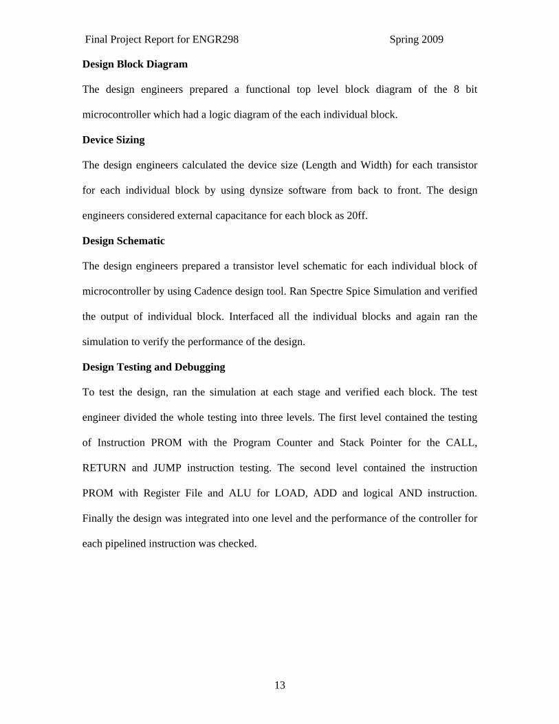
Design Block Diagram
The design engineers prepared a functional top level block diagram of the 8 bit
microcontroller which had a logic diagram of the each individual block.
Device Sizing
The design engineers calculated the device size (Length and Width) for each transistor
for each individual block by using dynsize software from back to front. The design
engineers considered external capacitance for each block as 20ff.
Design Schematic
The design engineers prepared a transistor level schematic for each individual block of
microcontroller by using Cadence design tool. Ran Spectre Spice Simulation and verified
the output of individual block. Interfaced all the individual blocks and again ran the
simulation to verify the performance of the design.
Design Testing and Debugging
To test the design, ran the simulation at each stage and verified each block. The test
engineer divided the whole testing into three levels. The first level contained the testing
of Instruction PROM with the Program Counter and Stack Pointer for the CALL,
RETURN and JUMP instruction testing. The second level contained the instruction
PROM with Register File and ALU for LOAD, ADD and logical AND instruction.
Finally the design was integrated into one level and the performance of the controller for
each pipelined instruction was checked.
Final Project Report for ENGR298 Spring 2009
14
3. Literature Survey on Microcontroller
3.1 Basic Processor Microprocessor is the heart of Computers. The basic components of Microprocessor are
Arithmetic and Control unit, memory, input/output devices.
Memory (ROM/RAM): All the instructions to be executed by the Microprocessor are
written in Read Only Memory (ROM).
Random Access memory (RAM) is used for permanent storage of data. The data can be
written to a RAM block or data can be read from RAM block. RAM stores the data as
long as power is supplied to it.
Arithmetic Logic Unit (ALU): ALU performs all the logical and arithmetic operations.
Control Unit: The control unit is required to move the data from ROM to ALU. The
control unit consists of Instruction Decoder and Register File.
Instruction decoder is used to decode the Instructions and Register File is used for the
temporary storage of data.
Input/output Devices: The Input Devices are usually Tri- State Buffers and Output
Devices are Latches.
In 1971, Intel obtained a first 4-bit microprocessor called 4004 running with speed
of 6000 Instructions per second. The following table shows the list of Microcontrollers
developed by Intel.
Final Project Report for ENGR298 Spring 2009
15
Table 1 Historical Development of Intel Microcontrollers Name Year Transistors Clock Speed
8080 1974 6000 2 MHz
8088 1979 29000 5 MHz
80286 1982 134000 6 MHz
80386 1985 275000 16 MHz
80486 1989 1200,000 25 MHz
Pentium 1993 3100,000 60 MHz
Pentium II 1997 7500,000 233 MHz
Pentium III 1999 9500,000 450 MHz
Pentium 4 2000 42000,000 1.5 GHz
Source: http://computer.howstuffworks.com/microprocessor1.htm.Table of our own
3.2 Basic Microcontroller “A microcontroller (also microcontroller unit, MCU or µC) is a small computer on a
single integrated circuit consisting of a relatively simple CPU combined with support
functions. Microcontrollers are used in automatically controlled products and devices,
such as automobile engine control systems, remote controls, office machines, appliances,
power tools, and toys. By reducing the size and cost compared to a design that uses a
separate microprocessor, memory, and input/output devices, microcontrollers make it
economical to digitally control even more devices and processes.”( Wikipedia) There are
several types of the microcontroller are available in the market like
Final Project Report for ENGR298 Spring 2009
16
8051
68HC11
eZ8, eZ80
Hitachi H8, SuperH
Rabbit 2000
TLCS-870
MSP430 (16-bit)
CF (32-bit)
ARM
MIPS (32-bit PIC32)
S08
AVR
PIC (8-bit PIC16, PIC18, 16-bit dsPIC33 / PIC24)
V850
PowerPC ISE
PSoC (Programmable System-on-Chip)
3.3 Difference between Microcontroller and Microprocessor Microcontroller is an integrated type of microprocessor. It has many characteristics like
low power consumption, self-sufficiency and cost-effectiveness as compared to general-
purpose microprocessor. The following figure shows difference between Microcontroller
and Microprocessor.
Final Project Report for ENGR298 Spring 2009
17
Figure 2 Comparison between Microprocessor and Microcontroller Source: Xilinx Micro Blaze Microcontroller Reference Design User Guide
The general purpose Register, Arithmetic Logic Unit, program counter, RAM, EPROM,
I/Os, Interrupt and Reset are the basic functional blocks of microcontroller.
Microcontroller differs from a microprocessor in many ways. “In order for a
microprocessor to be used, other components such as memory, or components for
receiving and sending data must be added to it. In short that means that microprocessor is
the heart of the computer. On the other hand, microcontroller is designed to be all of that
in one. No other external components are needed for its application because all necessary
peripherals are already built into it.” (Margarida F. Jacome, 2000).
3.4 Why 8 bit Microcontroller Commonly used Microcontrollers are
• 8 bit
• 16 bit
• 32 bit
Final Project Report for ENGR298 Spring 2009
18
The above three vary in terms of memory size, number of registers, address bus and data
bus. The market demand is high for 8 bit Microcontrollers because they are less
expensive as compared to 16 and 32 bit microcontrollers. It is possible to add new
functions to an 8 bit Microcontroller in a more creative way as compared to 16 bit or 32
bit. “The 8-bit MCU continues to be the workhorse of the automotive industry. It is
valued because of its cost-effective control functions, which enable consumers to enjoy
the benefits of smart products in the automobile sector. For example, the BMW 745i
luxury sedan contains more than sixty 8-bit MCUs.” (Meghan Le, 2004)
3.5 Embedded Microcontroller Microcontroller that is embedded inside some machine like Mobile devices, Automobile
Transmission systems, Video games is known as Embedded Microcontroller. An
Embedded Microcontroller has a smaller internal memory, an ALU, Control unit and
some I/O devices. The Embedded Microcontroller usually has a requirement of faster
speed and higher performance as compared to conventional Microcontrollers.
3.6 Applications of Embedded Microcontrollers Embedded Microcontrollers are used for various applications in the market.
- Automobiles
- Cameras
- Cell Phone
- Game Players
- Consumer Appliances
- Industrial Control
- Communication Devices
Final Project Report for ENGR298 Spring 2009
19
- Robotics
Embedded Microcontrollers are used for high speed applications like in communication
systems and in digital signal processing.
3.7 Pico Blaze 8-bit Embedded Microcontroller Pico Blaze Microcontroller is soft core fully embedded 8 bit microcontroller that
requires no external sources. Pico Blaze microcontroller provides a flexible I/O at much
lower cost than off the shelf controller. Pico Blaze can be customized to meet specific
features, function and cost requirements. It can perform a 44 to 100 MIPS with clock
speed of 200MHz. It provides very flexible architecture (Xilinx Pico Blaze 8 BIT
Embedded Microcontroller guide, June 2004).
Hard core processors are much faster and fixed in position where as soft core are
comparatively slower and can be placed any where. There are many other problems
customers are facing with the soft core processor. (Jim Duckworth , Embedded
Microprocessor).
Final Project Report for ENGR298 Spring 2009
20
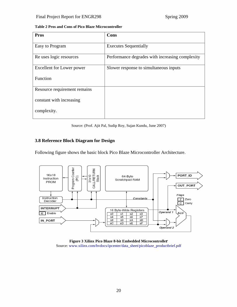
Table 2 Pros and Cons of Pico Blaze Microcontroller
Source: (Prof. Ajit Pal, Sudip Roy, Sujan Kundu, June 2007)
3.8 Reference Block Diagram for Design Following figure shows the basic block Pico Blaze Microcontroller Architecture.
Figure 3 Xilinx Pico Blaze 8-bit Embedded Microcontroller Source: www.xilinx.com/bvdocs/ipcenter/data_sheet/picoblaze_productbrief.pdf
Pros Cons
Easy to Program Executes Sequentially
Re uses logic resources Performance degrades with increasing complexity
Excellent for Lower power
Function
Slower response to simultaneous inputs
Resource requirement remains
constant with increasing
complexity.
Final Project Report for ENGR298 Spring 2009
21
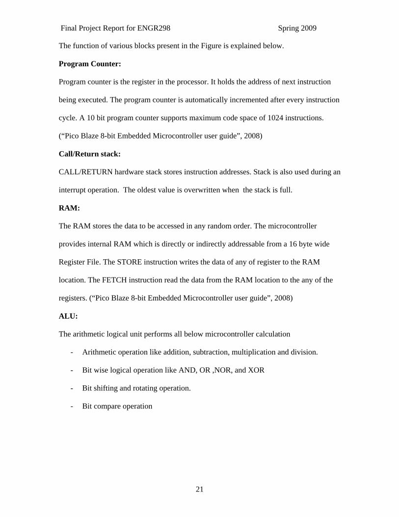
The function of various blocks present in the Figure is explained below.
Program Counter:
Program counter is the register in the processor. It holds the address of next instruction
being executed. The program counter is automatically incremented after every instruction
cycle. A 10 bit program counter supports maximum code space of 1024 instructions.
(“Pico Blaze 8-bit Embedded Microcontroller user guide”, 2008)
Call/Return stack:
CALL/RETURN hardware stack stores instruction addresses. Stack is also used during an
interrupt operation. The oldest value is overwritten when the stack is full.
RAM:
The RAM stores the data to be accessed in any random order. The microcontroller
provides internal RAM which is directly or indirectly addressable from a 16 byte wide
Register File. The STORE instruction writes the data of any of register to the RAM
location. The FETCH instruction read the data from the RAM location to the any of the
registers. (“Pico Blaze 8-bit Embedded Microcontroller user guide”, 2008)
ALU:
The arithmetic logical unit performs all below microcontroller calculation
- Arithmetic operation like addition, subtraction, multiplication and division.
- Bit wise logical operation like AND, OR ,NOR, and XOR
- Bit shifting and rotating operation.
- Bit compare operation
Final Project Report for ENGR298 Spring 2009
22
Register Bank:
The microcontroller has general purpose registers which can store both the data and
address. The register provides the way to access the data. The registers do not provide
any special function.
4. Design of Pico Blaze 8- Bit Microcontroller The IP design of an 8-bit Embedded Microcontroller has been designed using Custom
Design approach. The design is a transistor level design where the sizing has been done
using Dynsize program at every level.
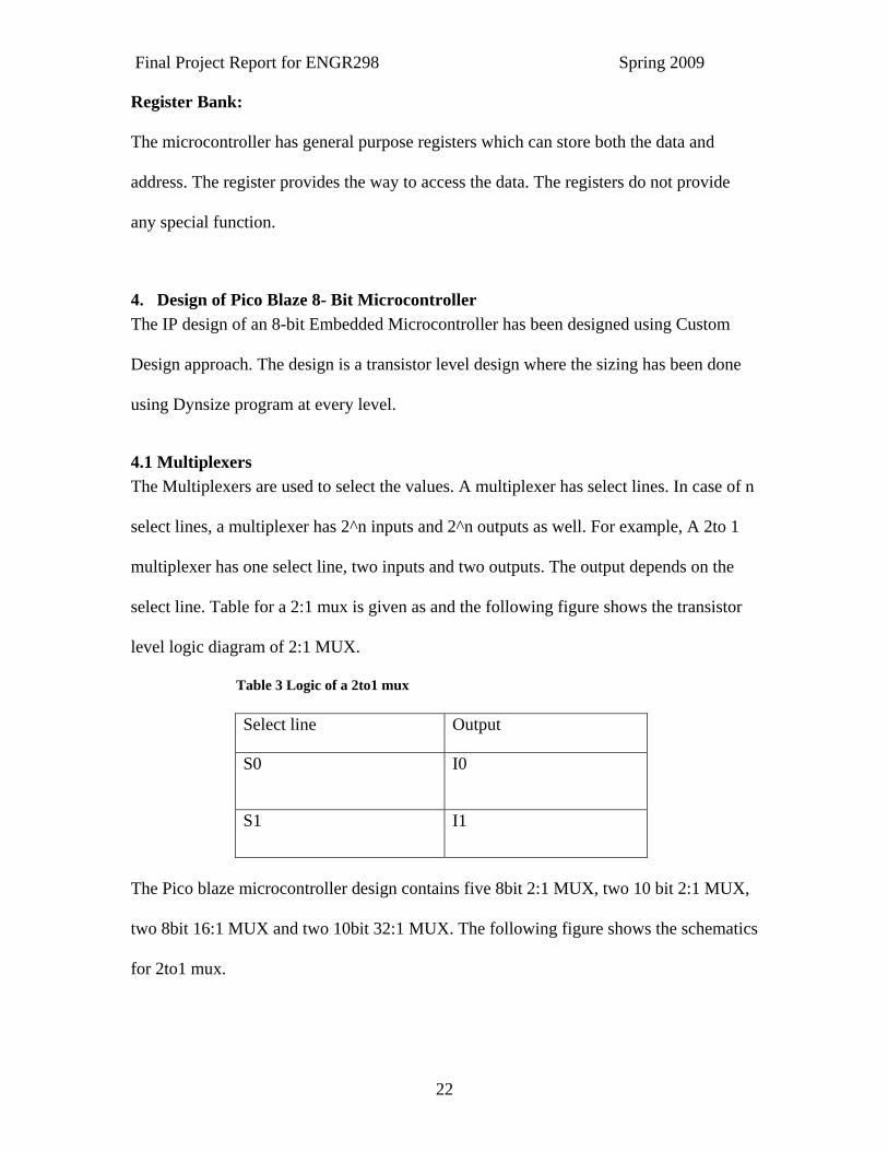
4.1 Multiplexers The Multiplexers are used to select the values. A multiplexer has select lines. In case of n
select lines, a multiplexer has 2^n inputs and 2^n outputs as well. For example, A 2to 1
multiplexer has one select line, two inputs and two outputs. The output depends on the
select line. Table for a 2:1 mux is given as and the following figure shows the transistor
level logic diagram of 2:1 MUX.
Table 3 Logic of a 2to1 mux
Select line Output
S0 I0
S1 I1
The Pico blaze microcontroller design contains five 8bit 2:1 MUX, two 10 bit 2:1 MUX,
two 8bit 16:1 MUX and two 10bit 32:1 MUX. The following figure shows the schematics
for 2to1 mux.
Final Project Report for ENGR298 Spring 2009
23
Figure 4 Transistor level schematics of 2to1 mux
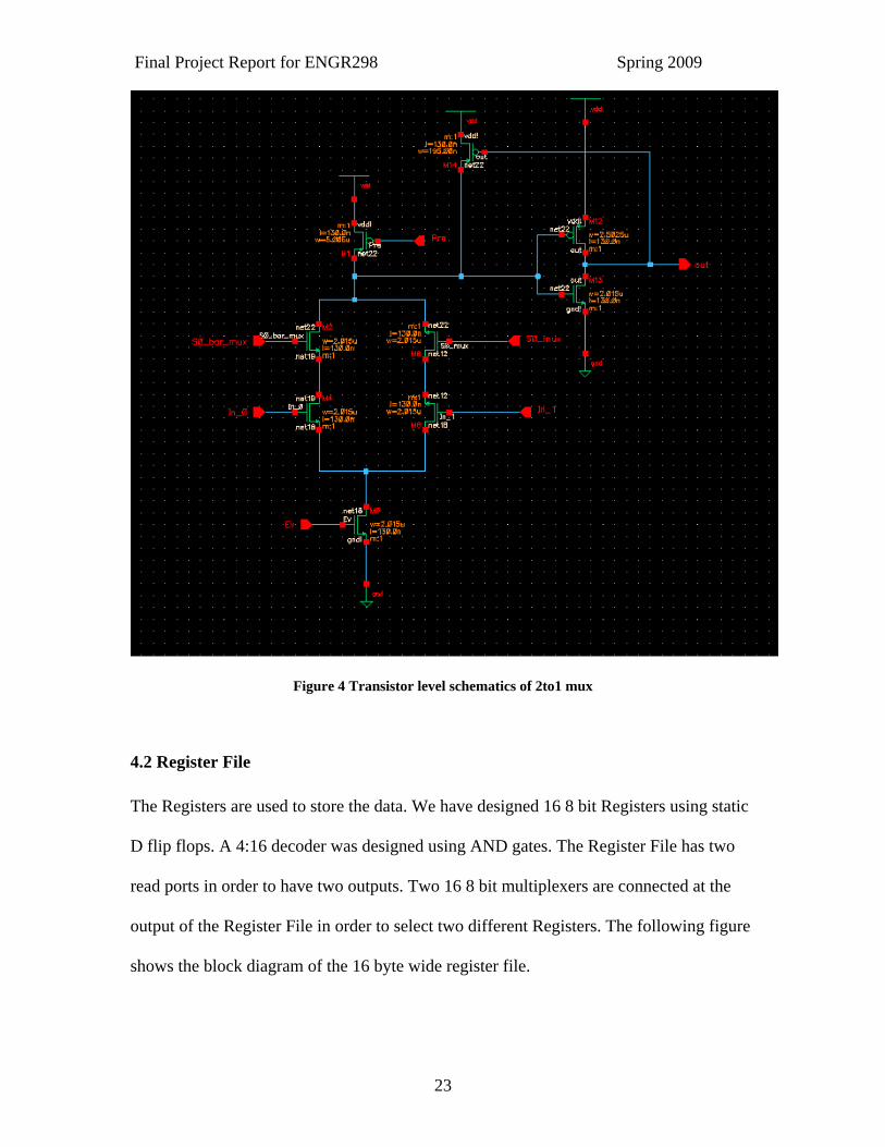
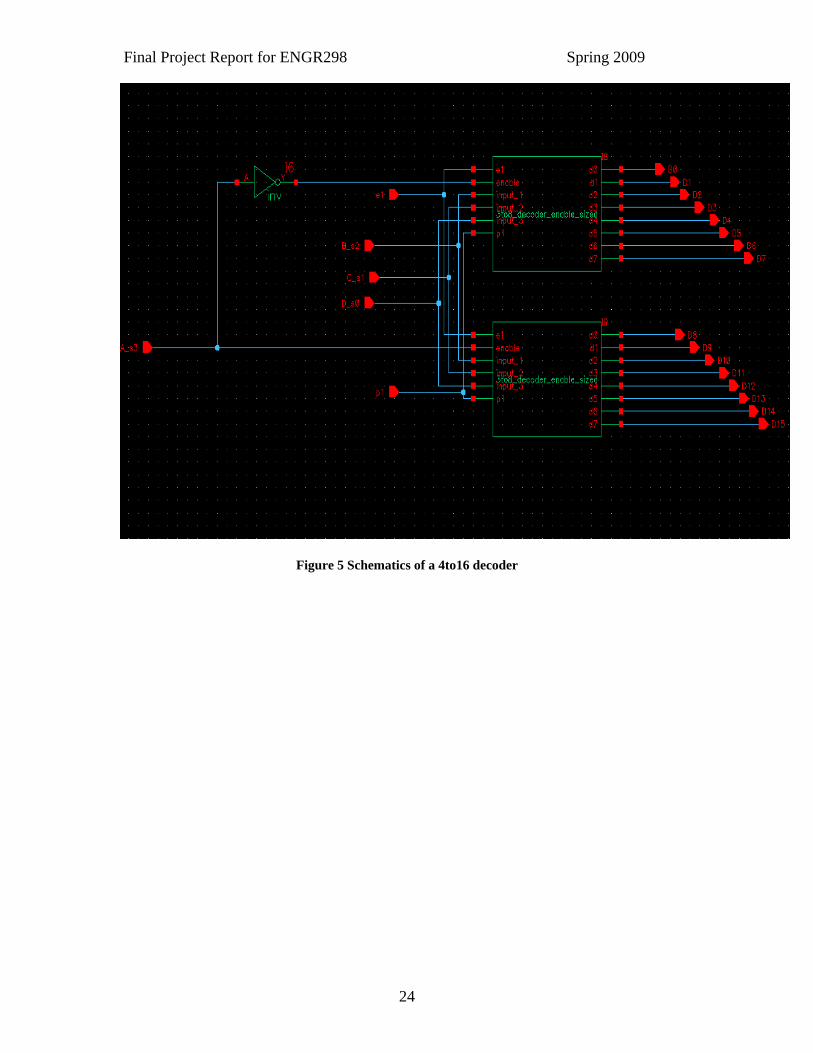
4.2 Register File The Registers are used to store the data. We have designed 16 8 bit Registers using static
D flip flops. A 4:16 decoder was designed using AND gates. The Register File has two
read ports in order to have two outputs. Two 16 8 bit multiplexers are connected at the
output of the Register File in order to select two different Registers. The following figure
shows the block diagram of the 16 byte wide register file.
Final Project Report for ENGR298 Spring 2009
24
Figure 5 Schematics of a 4to16 decoder
Final Project Report for ENGR298 Spring 2009
25
Figure 6 Schematics of 16 byte wide Register File
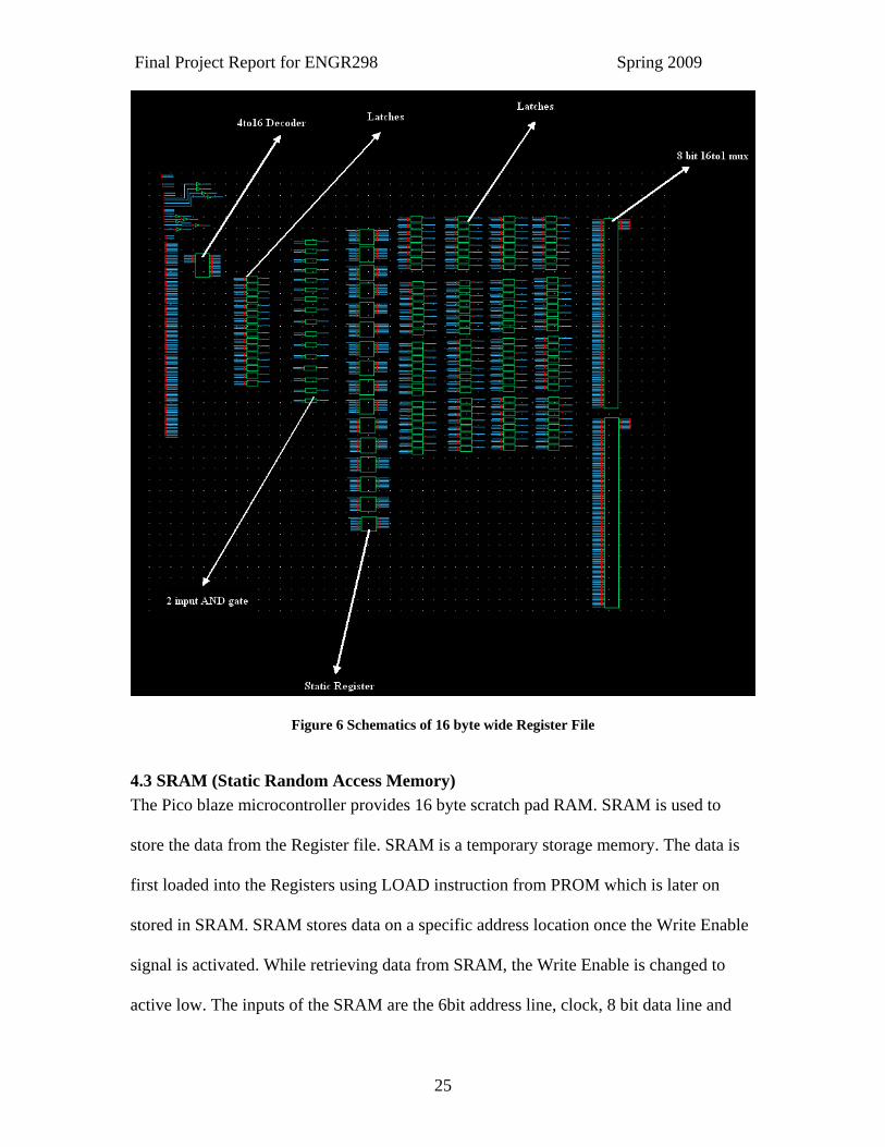
4.3 SRAM (Static Random Access Memory) The Pico blaze microcontroller provides 16 byte scratch pad RAM. SRAM is used to
store the data from the Register file. SRAM is a temporary storage memory. The data is
first loaded into the Registers using LOAD instruction from PROM which is later on
stored in SRAM. SRAM stores data on a specific address location once the Write Enable
signal is activated. While retrieving data from SRAM, the Write Enable is changed to
active low. The inputs of the SRAM are the 6bit address line, clock, 8 bit data line and
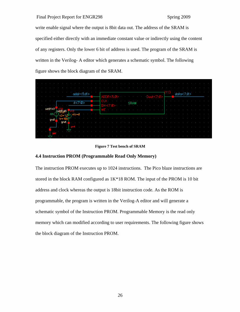
Final Project Report for ENGR298 Spring 2009
26
write enable signal where the output is 8bit data out. The address of the SRAM is
specified either directly with an immediate constant value or indirectly using the content
of any registers. Only the lower 6 bit of address is used. The program of the SRAM is
written in the Verilog- A editor which generates a schematic symbol. The following
figure shows the block diagram of the SRAM.
Figure 7 Test bench of SRAM
4.4 Instruction PROM (Programmable Read Only Memory) The instruction PROM executes up to 1024 instructions. The Pico blaze instructions are
stored in the block RAM configured as 1K*18 ROM. The input of the PROM is 10 bit
address and clock whereas the output is 18bit instruction code. As the ROM is
programmable, the program is written in the Verilog-A editor and will generate a
schematic symbol of the Instruction PROM. Programmable Memory is the read only
memory which can modified according to user requirements. The following figure shows
the block diagram of the Instruction PROM.
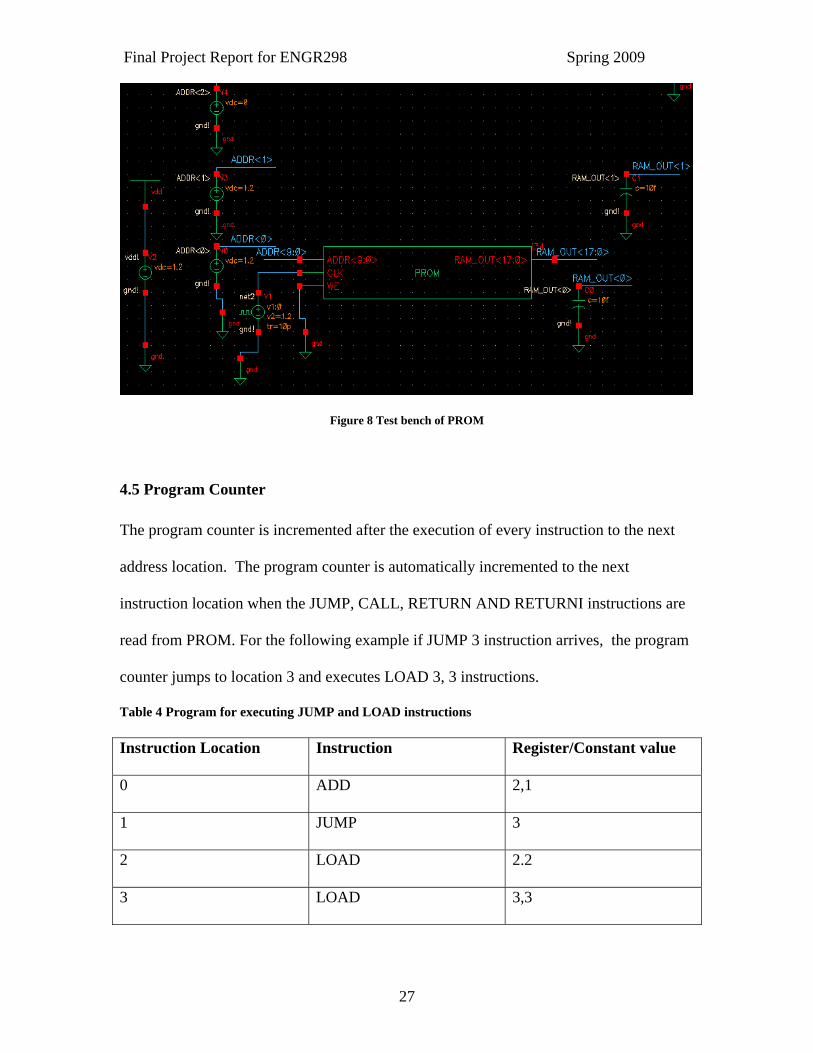
Final Project Report for ENGR298 Spring 2009
27
Figure 8 Test bench of PROM
4.5 Program Counter The program counter is incremented after the execution of every instruction to the next
address location. The program counter is automatically incremented to the next
instruction location when the JUMP, CALL, RETURN AND RETURNI instructions are
read from PROM. For the following example if JUMP 3 instruction arrives, the program
counter jumps to location 3 and executes LOAD 3, 3 instructions.
Table 4 Program for executing JUMP and LOAD instructions Instruction Location Instruction Register/Constant value
0 ADD 2,1
1 JUMP 3
2 LOAD 2.2
3 LOAD 3,3
Final Project Report for ENGR298 Spring 2009
28
The length of the program counter in Pico blaze microcontroller is 10 bit which supports
maximum code space of 1024 instructions (000 to 3FF). If the program counter reaches
to 3FF hex then again roll over to 000 locations. The following figure shows the basic
block diagram of the program counter which contains two 10 bit 2:1 multiplexer and 10
bit incrementer.
The carry look ahead adder (simple CLA) is used for the incrementer design in which all
the generate signals are zero.
Figure 9 Schematic of 10-bit Program Counter

Final Project Report for ENGR298 Spring 2009
29
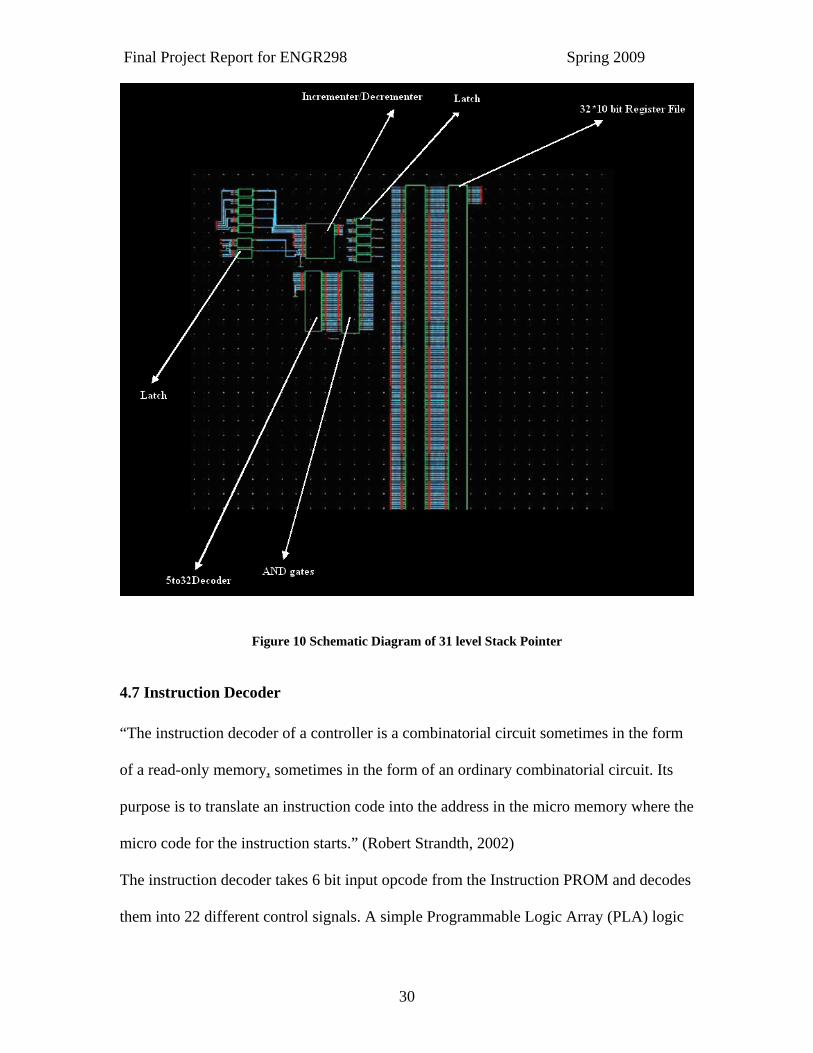
4.6 Stack Pointer The stack pointer stores up to 31 address locations and each instruction location is 10 bits
wide. The stack is also used during an interrupt operation. When the interrupt is enabled,
at least one of the stack locations should be reserved. The basic stack memory block
contains the 5bit counter which performs increment and decrement, 5:32 bit decoder, 32
bit register and 32:1 10 bit MUX. The following figure shows the basic block diagram of
the stack memory.
The simple 5-bit Carry Look Ahead counter (CLA) is used for the up and down counter
with 2:1 mux at input and at output. If the select line of the 2:1 mux is 1, the counter will
decrement and if its 0 then counter is increment.
Final Project Report for ENGR298 Spring 2009
30
Figure 10 Schematic Diagram of 31 level Stack Pointer
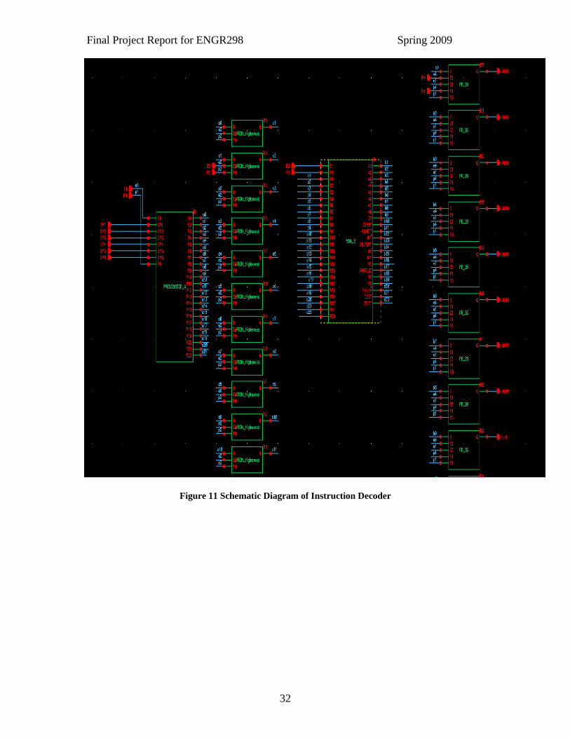
4.7 Instruction Decoder “The instruction decoder of a controller is a combinatorial circuit sometimes in the form
of a read-only memory, sometimes in the form of an ordinary combinatorial circuit. Its
purpose is to translate an instruction code into the address in the micro memory where the
micro code for the instruction starts.” (Robert Strandth, 2002)
The instruction decoder takes 6 bit input opcode from the Instruction PROM and decodes
them into 22 different control signals. A simple Programmable Logic Array (PLA) logic

Final Project Report for ENGR298 Spring 2009
31
is used to design the instruction decoder. There are two main parts of instruction decoder,
one is Pre decoder and other one is ROM. According to the different instructions
mentioned in the APPENDIX-A, the design engineers designed twenty two control
signals and then reduced the control signal logic by using Espresso logic reduction tool.
The result of that tool is mention in APPENDIX-C. At a time only one row line goes high
and accordingly the column line goes low and is then passed through inverter. The
following figure shows the block diagram of the instruction decoder, pre decoder and
ROM design.
Final Project Report for ENGR298 Spring 2009
32
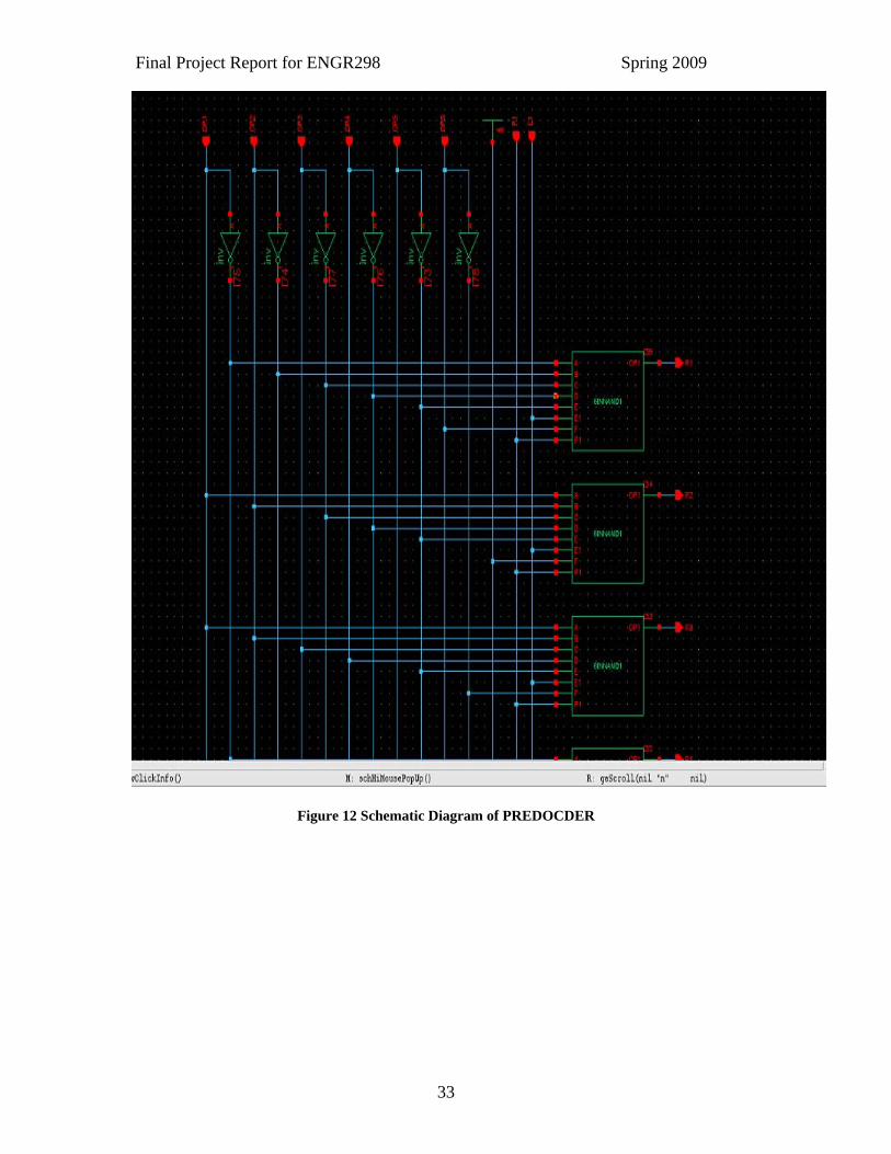
Figure 11 Schematic Diagram of Instruction Decoder
Final Project Report for ENGR298 Spring 2009
33
Figure 12 Schematic Diagram of PREDOCDER
Final Project Report for ENGR298 Spring 2009
34
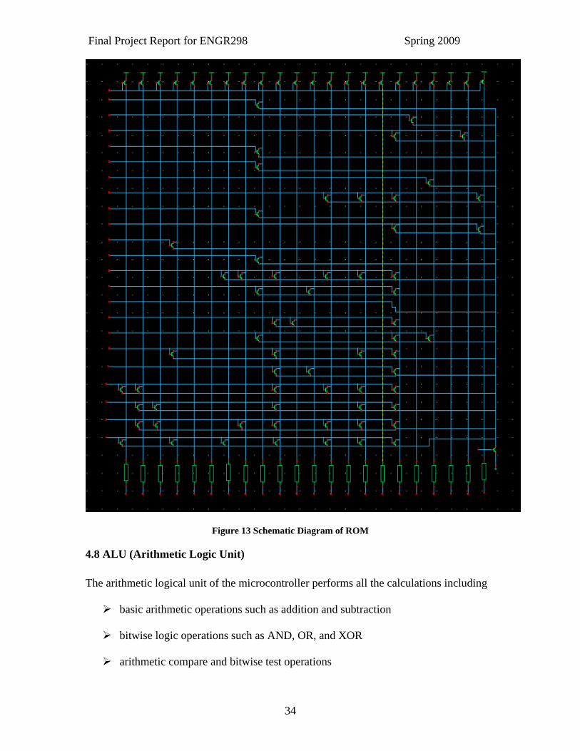
Figure 13 Schematic Diagram of ROM
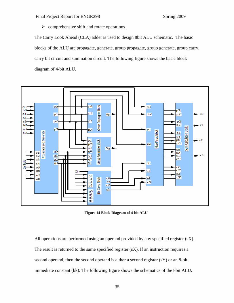
4.8 ALU (Arithmetic Logic Unit) The arithmetic logical unit of the microcontroller performs all the calculations including
basic arithmetic operations such as addition and subtraction
bitwise logic operations such as AND, OR, and XOR
arithmetic compare and bitwise test operations
Final Project Report for ENGR298 Spring 2009
35
comprehensive shift and rotate operations
The Carry Look Ahead (CLA) adder is used to design 8bit ALU schematic. The basic
blocks of the ALU are propagate, generate, group propagate, group generate, group carry,
carry bit circuit and summation circuit. The following figure shows the basic block
diagram of 4-bit ALU.
All operations are performed using an operand provided by any specified register (sX).
The result is returned to the same specified register (sX). If an instruction requires a
second operand, then the second operand is either a second register (sY) or an 8-bit
immediate constant (kk). The following figure shows the schematics of the 8bit ALU.
Figure 14 Block Diagram of 4-bit ALU
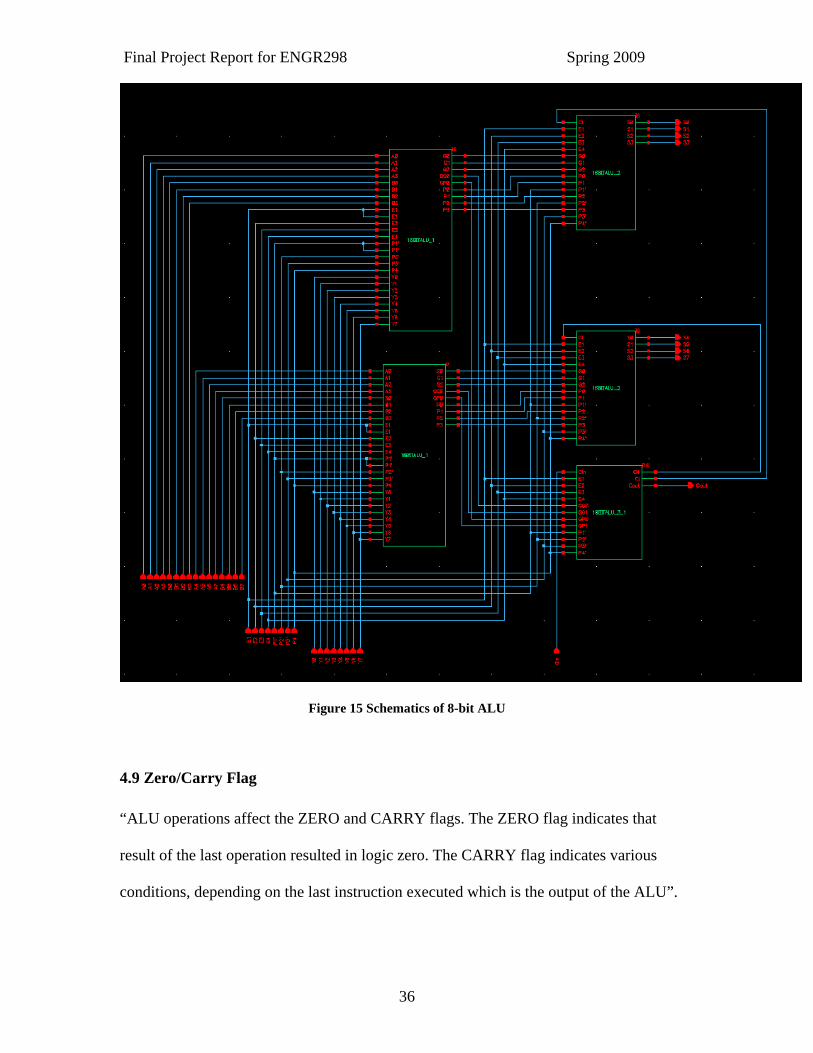
Final Project Report for ENGR298 Spring 2009
36
Figure 15 Schematics of 8-bit ALU
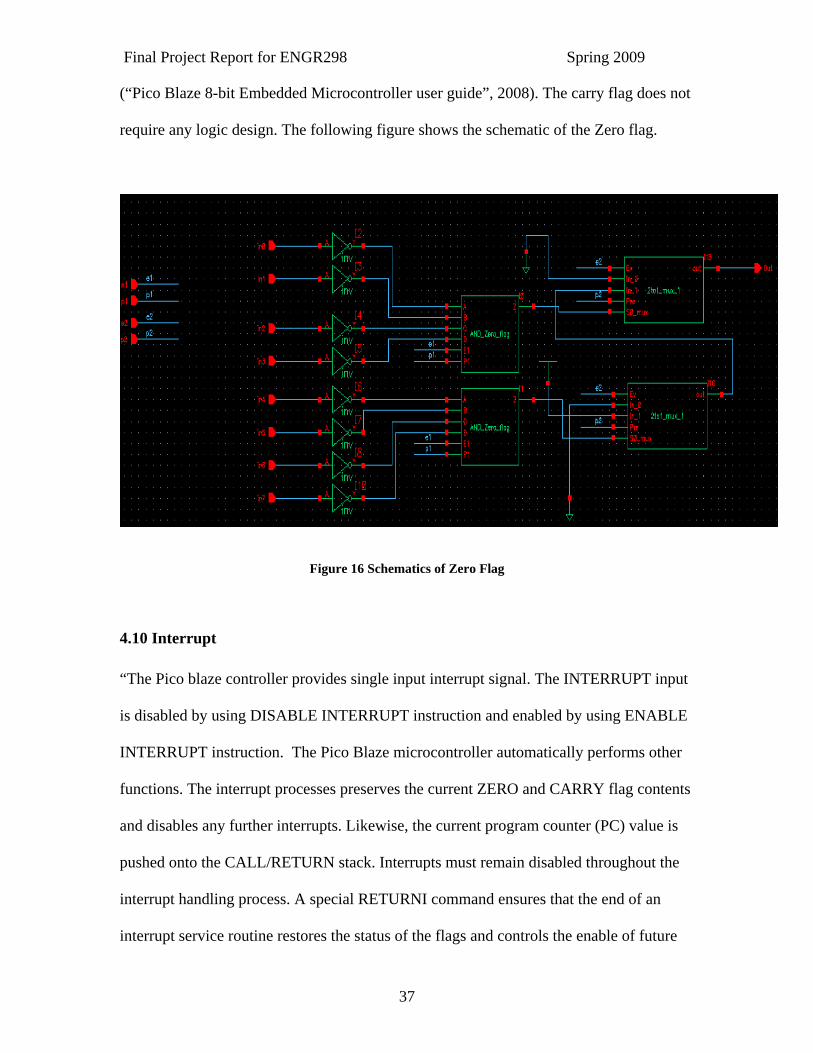
4.9 Zero/Carry Flag “ALU operations affect the ZERO and CARRY flags. The ZERO flag indicates that
result of the last operation resulted in logic zero. The CARRY flag indicates various
conditions, depending on the last instruction executed which is the output of the ALU”.
Final Project Report for ENGR298 Spring 2009
37
(“Pico Blaze 8-bit Embedded Microcontroller user guide”, 2008). The carry flag does not
require any logic design. The following figure shows the schematic of the Zero flag.
Figure 16 Schematics of Zero Flag
4.10 Interrupt “The Pico blaze controller provides single input interrupt signal. The INTERRUPT input
is disabled by using DISABLE INTERRUPT instruction and enabled by using ENABLE
INTERRUPT instruction. The Pico Blaze microcontroller automatically performs other
functions. The interrupt processes preserves the current ZERO and CARRY flag contents
and disables any further interrupts. Likewise, the current program counter (PC) value is
pushed onto the CALL/RETURN stack. Interrupts must remain disabled throughout the
interrupt handling process. A special RETURNI command ensures that the end of an
interrupt service routine restores the status of the flags and controls the enable of future
Final Project Report for ENGR298 Spring 2009
38
interrupts. When the RETURNI instruction is executed, the PC values saved onto the
CALL/RETURN stack is automatically reloaded to the PC register. Likewise, the ZERO
and CARRY flags are restored and program flow returns to the instruction following the
instruction where the interrupt occurred. If the application does not require an interrupt,
tie the INTERRUPT signal Low.” (“Pico Blaze 8-bit Embedded Microcontroller user
guide”, 2008)
4.11 Input and Output “The Input/Output ports extend the Pico Blaze microcontroller’s capabilities and allow
the microcontroller to connect to a custom peripheral set or to other FPGA logic. The
PORT_ID output provides the port address. During an INPUT operation, the Pico Blaze
microcontroller reads data from the IN_PORT port to a specified register, sX. During an
OUTPUT operation, the Pico Blaze microcontroller writes the contents of a specified
register, sX, to the OUT_PORT port. Input sources are generally selected via a
multiplexer”. (“Pico Blaze 8-bit Embedded Microcontroller user guide”, 2008)
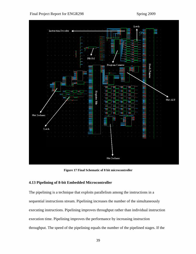
4.12 Interfacing of Top level Blocks The following block diagram shows the final interfacing of the each block which follows
the reference block diagram of the Pico blaze microcontroller.
Final Project Report for ENGR298 Spring 2009
39
Figure 17 Final Schematic of 8 bit microcontroller
4.13 Pipelining of 8-bit Embedded Microcontroller The pipelining is a technique that exploits parallelism among the instructions in a
sequential instructions stream. Pipelining increases the number of the simultaneously
executing instructions. Pipelining improves throughput rather than individual instruction
execution time. Pipelining improves the performance by increasing instruction
throughput. The speed of the pipelining equals the number of the pipelined stages. If the
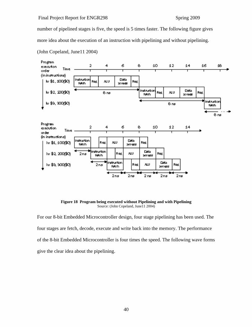
Final Project Report for ENGR298 Spring 2009
40
number of pipelined stages is five, the speed is 5 times faster. The following figure gives
more idea about the execution of an instruction with pipelining and without pipelining.
(John Copeland, June11 2004)
Figure 18 Program being executed without Pipelining and with Pipelining Source: (John Copeland, June11 2004)
For our 8-bit Embedded Microcontroller design, four stage pipelining has been used. The
four stages are fetch, decode, execute and write back into the memory. The performance
of the 8-bit Embedded Microcontroller is four times the speed. The following wave forms
give the clear idea about the pipelining.
Final Project Report for ENGR298 Spring 2009
41
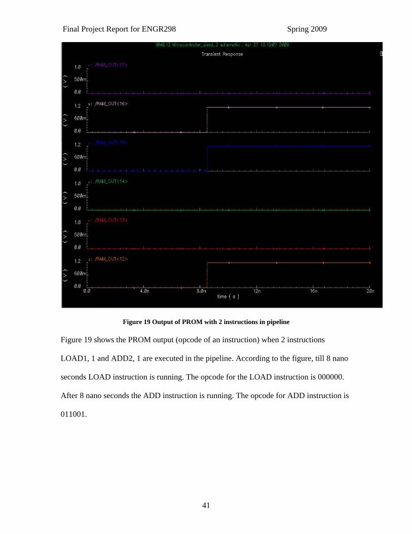
Figure 19 Output of PROM with 2 instructions in pipeline Figure 19 shows the PROM output (opcode of an instruction) when 2 instructions
LOAD1, 1 and ADD2, 1 are executed in the pipeline. According to the figure, till 8 nano
seconds LOAD instruction is running. The opcode for the LOAD instruction is 000000.
After 8 nano seconds the ADD instruction is running. The opcode for ADD instruction is
011001.
Final Project Report for ENGR298 Spring 2009
42
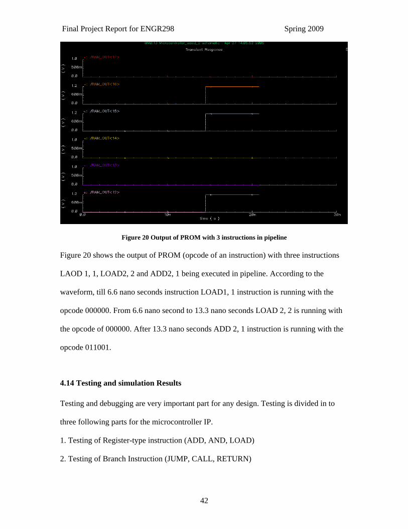
Figure 20 Output of PROM with 3 instructions in pipeline Figure 20 shows the output of PROM (opcode of an instruction) with three instructions
LAOD 1, 1, LOAD2, 2 and ADD2, 1 being executed in pipeline. According to the
waveform, till 6.6 nano seconds instruction LOAD1, 1 instruction is running with the
opcode 000000. From 6.6 nano second to 13.3 nano seconds LOAD 2, 2 is running with
the opcode of 000000. After 13.3 nano seconds ADD 2, 1 instruction is running with the
opcode 011001.
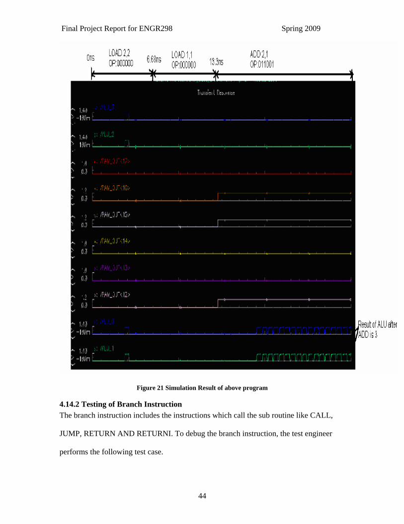
4.14 Testing and simulation Results Testing and debugging are very important part for any design. Testing is divided in to
three following parts for the microcontroller IP.
1. Testing of Register-type instruction (ADD, AND, LOAD)
2. Testing of Branch Instruction (JUMP, CALL, RETURN)
Final Project Report for ENGR298 Spring 2009
43
3. Testing of small program
4.14.1 Testing of R-type (Register-type) instruction The Register-type instruction includes all the arithmetic, logical and memory related
instructions like ADD, logical AND, OR, SUBTRACT, LOAD, FETCH, STORE etc. In
order to test the Register-type instruction, the test engineer follows the following test case.
Table 5 Test Case for R- type Instructions Location Delay to Vpluse instruction
0 0 ns LOAD 2,2
1 6.68 ns LOAD 1,1
2 13.3 ns ADD 2,1
The design engineers did the four stages pipelining by using a vpluse at the input of the
instruction PROM. For LOAD 2, 2 instruction the register loads a constant value 2 to the
memory at address location2, similarly for LOAD1,1 instruction , the register loads
constant value1 at address location1 of memory. After 13.3 ns the ADD 2, 1 instruction
gives the addition of register 2 and register 1 at the output. Simulation result given below
explains the program execution in more detail.
Final Project Report for ENGR298 Spring 2009
44
Figure 21 Simulation Result of above program
4.14.2 Testing of Branch Instruction The branch instruction includes the instructions which call the sub routine like CALL,
JUMP, RETURN AND RETURNI. To debug the branch instruction, the test engineer
performs the following test case.
Final Project Report for ENGR298 Spring 2009
45
Table 6 Test case for Branch Instruction Location Delay to vpluse Instruction Value
0 0 JUMP 12
12 6.68 ns JUMP 10
10 13.3 ns JUMP 16
When the JUMP instruction located at the address location 12 is read from PROM, the
Program Counter is loaded with new address location and jumps to the instruction at
location 12, i.e. performs instruction JUMP 10.
4.14.3 Final Testing of the whole program For the final testing the test engineer follows two test cases.
Test case-1
The program is given in the table below.
Table 7 Program for the Final Testing, Test case1 . Address Location Instruction Constant/Register Value
0 LOAD 2,2
1 LOAD 1,1
2 ADD 2,1
3 JUMP 5
4 AND 2,1
5 LOAD 3,3
Final Project Report for ENGR298 Spring 2009
46
Test case-2
The program for the test case-2 is given in the table below.
Table 8 Program for the Final Testing, Test case2 Address Location Instruction Constant/Register Value
0 LOAD 2,2
1 LOAD 1,1
2 ADD 2,1
3 CALL 5
4 AND 2,1
5 LOAD 3,3
6 ADD 2,3
4.14.4 Results The transistor count in an 8-bit Embedded Microcontroller design is around 11,200. The
8-bit Embedded Microcontroller has been simulated for the frequency of 1.5GHz as per
Product specification. Almost a delay of 2ns is observed in the output waveforms.
4.15 Applications of 8-bit Embedded Microcontroller “According to the performance of our IP design microcontroller it will be used for the
following applications.”(Ken Chapman May 2007)
LED flasher.
PWM control and even generation (KHz PRF for motors and brightness control).
Switch monitor.
UART interface and simple command/status terminal.
Final Project Report for ENGR298 Spring 2009
47
LCD character module display interface and control.
SPI master (i.e. FLASH controller for Spartan-3AN).
I2C master.
Calculator.
Audio DSP processor (typically up to 48KHz sample rate and may utilize a
hardware multiplier as a peripheral)
DTMF tone telephone dialer including sine wave generation (8KHz sample rate)
System monitoring (e.g. Temperature monitor and fan control).
Motor control.
Rotary encoder interface.
Calculator for frequency synthesizer.
Calculator for filter coefficient generation.
Emulation of a different micro controller.
PID control.
Mouse/Keyboard interface.
Keypad scanner.
Power supply monitoring and control.
Servo control.
Built-in test equipment (on-chip monitor).
Configuration management (ICAP port)
Design Authentication Processor.
Source: Ken Chapman, May 2007

Final Project Report for ENGR298 Spring 2009
48
4.16 Future Expansion of 8 bit Embedded Microcontroller . “The global market System-on-Chip (SoC) market is expected to increase by more than
150% between the years 2006 and 2010. United States represents the world's largest SoC
market, worth an estimated US$10.4 billion in 2007, as stated in a recent report published
by Global Industry Analysts, Inc.”(“System-on-a-Chip Market to Exceed $58 Billion by
2010”, 2007)
Because of the increasing demand for SoCs in the market, our company will expand from
Microcontroller to SoC (System on Chip) to get an edge in high performance as
compared to our competitors.
Final Project Report for ENGR298 Spring 2009
49
5. Economic Justification The following economic justification proves that the project is economically feasible and
can generate good revenue.
5.1 Executive Summary The key activity of the company is to apply best strategies and translate those strategies
into specific target to achieve a specific goal. The Company’s product, an 8 bit
Embedded Microcontroller is targeted towards our customer requirements for high speed
and low cost. As compared to the competitors of Microcontroller market, the product
will achieve a good demand from the sectors like Consumer Electronics, Automotive and
Communication Systems market. The main problem with today’s microcontroller is the
performance. Pico Blaze Microcontroller from Xilinx, Inc., one of the best 8-bit
Embedded Microcontrollers in market at present is running with maximum speed of
700MHz. Pico blaze is the soft core controller and it is very hard to achieve performance
above MHz. Our product will eliminate the performance issue being faced by the current
microcontrollers in the market by providing IP design of an 8 bit microcontroller with
maximum clock frequency of 1.5 GHz. The product gives the flexibility to program,
higher performance and compact size to the customer. The company initially targets two
most growing markets like consumer electronics and automotive market for selling the IP
design. According to ST Microelectronics “The 8-bit MCU market for consumer
appliances, currently worth about $5 billion, is expected to continue showing healthy
growth, with unit shipments expected to exceed 6500M in 2011 compared to 4400M in
2007. In automotive applications alone, for example, unit growth between 2007 and 2013
is expected to be increases around 40%”. (ST Microelectronics, 2007)
Final Project Report for ENGR298 Spring 2009
50
According to US appliance unit shipment, the average no of unit manufacturer in the in
consumer electronics market for 2008 was 4,997,239 (Appliance Magazine, April 2009).
Based on this data the company is targeting approximately 4% of the market share.
The Company’s business model is very simple. The Company designs an IP and sells that
IP by charging license fee and royalty per unit sold. The NRE cost for the IP is
$75,000 for the first year and then it will increase up to $100K for the next four years.
The royalty fee for the customer is $10 per unit sold. The main customers of the company
will be consumer electronics appliance manufacturers like LG electronics, Sony,
Samsung etc. The Company requires initial an investment of $1.0 million. The company
will invest $500k from the personal investments and remaining $500K as loan from the
bank. The company will start selling the IP from 3rd quarter 2009 onwards and will break
even in the quarter-2 of the 2010.
5.2 Problem Statement Portability, High performance and Compact size are the characteristic trends in
Electronics Industry. Microcontroller is the device with a processor core and the number
of added peripherals and is widely used as embedded device in every equipment ranging
from small chip to high profile satellite system. Pico Blaze and Micro Blaze
microcontrollers are the soft core, limited by their performance. Every instruction
executes sequentially. As any application increases in complexity, the number of
instructions required implementing the application increases and system performance
decreases. Another problem with today’s microcontroller is timing. It is very difficult to
handle timing operation for higher frequency above 100MHz.
Final Project Report for ENGR298 Spring 2009
51
5.3 Solutions and Value Proposition
The solution to above problem is to design the microcontroller which is running at high
speed of 1.5GHz clock rate which can perform parallel processing of Instructions and
Eliminate timing problems. The developed 8bit microcontroller product works
with high performance by using 4 stage pipelining which overcome the performance
issue being faced by the current microcontrollers. Pipelining is a procedure that enables
several instructions to work simultaneously unlike Sequential processing, where every
instruction runs in a sequence. Pipelining improves instruction throughput. The project
supports the following features.
16 Byte wide general purpose data register
1K instructions of programmable on-chip program store.
Byte-wide Arithmetic Logic Unit (ALU) with CARRY and ZERO indicator flags.
64-byte internal Scratchpad RAM
31-location CALL/RETURN stack
Fast Interrupt response
Predictable performance up to 1.5GHz
The value proposition of this product line is the capability of this 8bit microcontroller
product to run at optimum speed of 1.5 GHz thus executing more instructions per second,
i.e. increased performance. The hardware implementation of an 8 bit microcontroller for
high performance will be advantageous for not only a consumer product but also a
Satellite system.
Final Project Report for ENGR298 Spring 2009
52
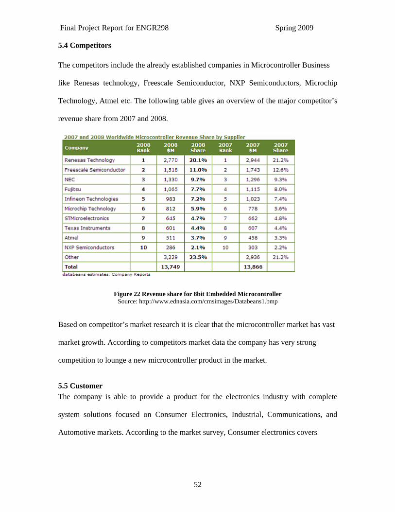
5.4 Competitors The competitors include the already established companies in Microcontroller Business
like Renesas technology, Freescale Semiconductor, NXP Semiconductors, Microchip
Technology, Atmel etc. The following table gives an overview of the major competitor’s
revenue share from 2007 and 2008.
Figure 22 Revenue share for 8bit Embedded Microcontroller Source: http://www.ednasia.com/cmsimages/Databeans1.bmp
Based on competitor’s market research it is clear that the microcontroller market has vast
market growth. According to competitors market data the company has very strong
competition to lounge a new microcontroller product in the market.
5.5 Customer The company is able to provide a product for the electronics industry with complete
system solutions focused on Consumer Electronics, Industrial, Communications, and
Automotive markets. According to the market survey, Consumer electronics covers
Final Project Report for ENGR298 Spring 2009
53
67% of the market share. The company’s targeted large customers are the consumer
electronics product manufacturer like LG Electronics, Sony, and Samsung etc. Secondly
company will focus on automotive industries because the automotive industries cover
33% of the market for microcontroller. The product is also used in security systems and
also for the communication devices. Company’s targeted medium and small customer
are the NEC Electronics, Tera sync Ltd, BAE system and etc.
5.6 Market Size of 8 bit Embedded Microcontroller “The worldwide microcontroller market was $16 billion in 2007, according to Frost &
Sullivan. The top two suppliers by revenue were shipping more than 10 different
incompatible architectures into the market. According to Semico, 8.5 billion MCUs
shipped in 2006. The MCU market has more than 40 suppliers feeding more than 50
architectures, with no architecture holding as much as a 5% share. Each vendor offers its
own designs with little commonality, feeding a broad applications base” (Jean Anne
Booth, January 2008). “STMicroelectronics, one of the market’s top mega-contestants,
estimates the overall 8-bit MCU market at $5 billion, with unit shipments expected to
grow 48 percent between 2007 and 2011.Freescale puts the number at $4.5 billion to $4.7
billion, with relatively flat dollar growth until 2011. And Atmel estimates the combined
8- and 16- bit MCU market is worth $11 billion, with plenty of new designs to win” ( Ed
Sperling, April 2008) . According to US appliance unit shipment, the average no of unit
manufacturer in the in consumer electronics market for 2008 is 4,997,239 (Appliance
Magazine, April 2009). Based on this data the company is targeting approximately 4% of
the market share.
By analyzing resources and the customer needs, the target market customers are
Final Project Report for ENGR298 Spring 2009
54
Consumer electronics industry, automotive manufactures and industrial manufactures.
The automotive manufactures covers 33% of the market and consumer electronics
industries and communication industries covers 67 % of the market (Ramanan
Rajgopalan, 2004).
5.6.1 Consumer Electronics “A microcontroller is an integrated microprocessor designed for use in embedded
systems. The focus is on control capabilities and cost-effectiveness for a given form
factor. All the memory, peripherals, and interfaces that are needed are included on the
chip with the CPU – the original system-on-chip device. The applications tend to feature
control over computation, and are interrupt-driven, requiring a real-time response to
stimulus. An embedded application or embedded system is any kind of electronic control
or computing application that is not a desktop, laptop, or server. The majority of all uses
of processors are in embedded applications, encompassing more than 6 billion
microcontrollers shipped a year”. (Gartner)
“The global sale of consumer electronics is estimated to exceed all expectations to touch
an all time high of $135.4 billion in 2006, which indicates 8% increase from 2005. By the
year 2008, sales are forecasted to soar up to $158.4 billion, up BY 65% over
2000.”(World wide consumer electronics market, 2006) A recent market research report
by the leading research company RNCOS showed that
US consumer electronics market gathered around US$ 144.5 Billion revenue in 2006, a
market growth of around 13% over the previous year as against the expected hike of 8%.
For 2007, the factory sales of consumer electronics in the country are estimated to rise to
over US$ 155 Billion.(World wide consumer electronics market, 2006)
Final Project Report for ENGR298 Spring 2009
55
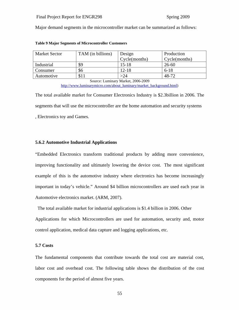
Major demand segments in the microcontroller market can be summarized as follows:
Table 9 Major Segments of Microcontroller Customers Market Sector TAM (in billions) Design
Cycle(months) Production Cycle(months)
Industrial $9 15-18 26-60 Consumer $6 12-18 6-18 Automotive $11 >24 48-72
Source: Luminary Market, 2006-2009 http://www.luminarymicro.com/about_luminary/market_background.html)
The total available market for Consumer Electronics Industry is $2.3billion in 2006. The
segments that will use the microcontroller are the home automation and security systems
, Electronics toy and Games.
5.6.2 Automotive Industrial Applications “Embedded Electronics transform traditional products by adding more convenience,
improving functionality and ultimately lowering the device cost. The most significant
example of this is the automotive industry where electronics has become increasingly
important in today’s vehicle.” Around $4 billion microcontrollers are used each year in
Automotive electronics market. (ARM, 2007).
The total available market for industrial applications is $1.4 billion in 2006. Other
Applications for which Microcontrollers are used for automation, security and, motor
control application, medical data capture and logging applications, etc.
5.7 Costs The fundamental components that contribute towards the total cost are material cost,
labor cost and overhead cost. The following table shows the distribution of the cost
components for the period of almost five years.
Final Project Report for ENGR298 Spring 2009
56
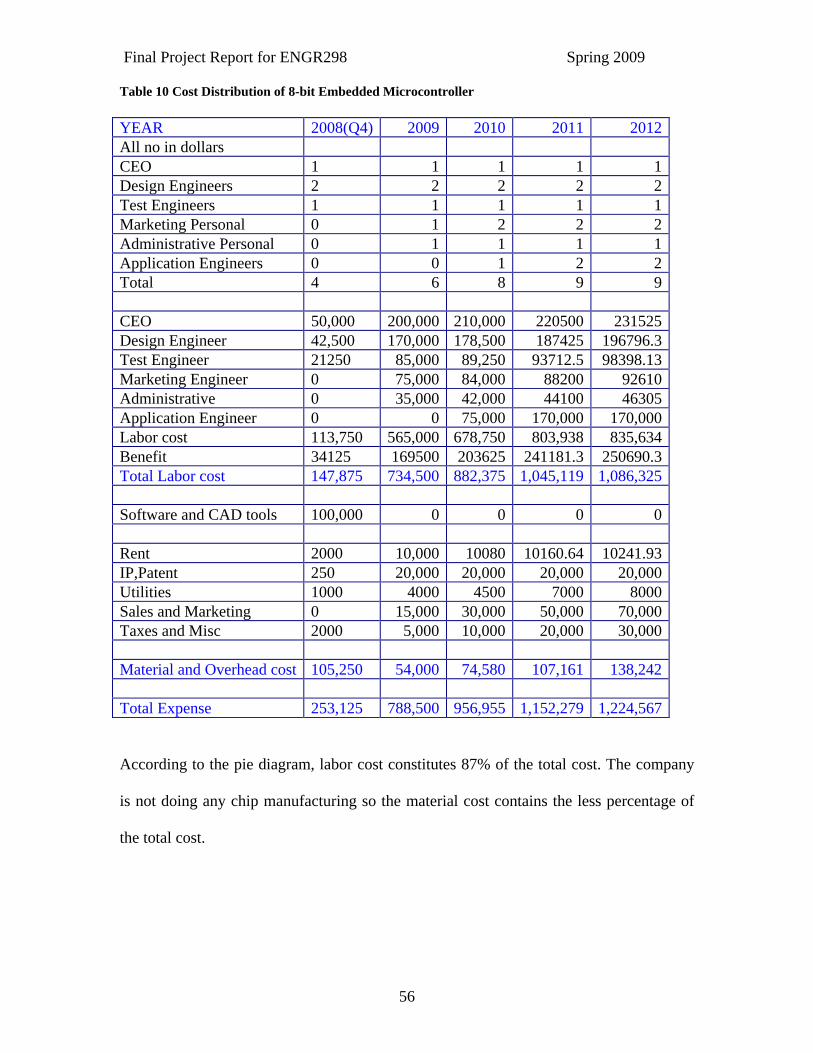
Table 10 Cost Distribution of 8-bit Embedded Microcontroller YEAR 2008(Q4) 2009 2010 2011 2012All no in dollars CEO 1 1 1 1 1Design Engineers 2 2 2 2 2Test Engineers 1 1 1 1 1Marketing Personal 0 1 2 2 2Administrative Personal 0 1 1 1 1Application Engineers 0 0 1 2 2Total 4 6 8 9 9 CEO 50,000 200,000 210,000 220500 231525Design Engineer 42,500 170,000 178,500 187425 196796.3Test Engineer 21250 85,000 89,250 93712.5 98398.13Marketing Engineer 0 75,000 84,000 88200 92610Administrative 0 35,000 42,000 44100 46305Application Engineer 0 0 75,000 170,000 170,000Labor cost 113,750 565,000 678,750 803,938 835,634Benefit 34125 169500 203625 241181.3 250690.3Total Labor cost 147,875 734,500 882,375 1,045,119 1,086,325 Software and CAD tools 100,000 0 0 0 0 Rent 2000 10,000 10080 10160.64 10241.93IP,Patent 250 20,000 20,000 20,000 20,000Utilities 1000 4000 4500 7000 8000Sales and Marketing 0 15,000 30,000 50,000 70,000Taxes and Misc 2000 5,000 10,000 20,000 30,000 Material and Overhead cost 105,250 54,000 74,580 107,161 138,242 Total Expense 253,125 788,500 956,955 1,152,279 1,224,567
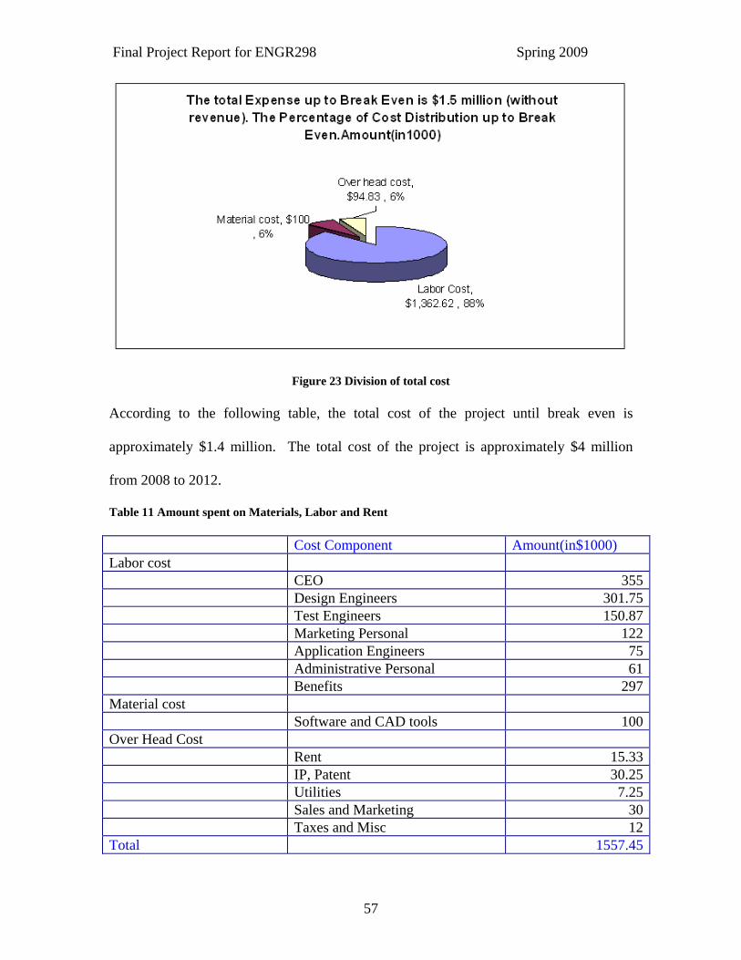
According to the pie diagram, labor cost constitutes 87% of the total cost. The company
is not doing any chip manufacturing so the material cost contains the less percentage of
the total cost.
Final Project Report for ENGR298 Spring 2009
57
Figure 23 Division of total cost According to the following table, the total cost of the project until break even is
approximately $1.4 million. The total cost of the project is approximately $4 million
from 2008 to 2012.
Table 11 Amount spent on Materials, Labor and Rent Cost Component Amount(in$1000) Labor cost CEO 355 Design Engineers 301.75 Test Engineers 150.87 Marketing Personal 122 Application Engineers 75 Administrative Personal 61 Benefits 297Material cost Software and CAD tools 100Over Head Cost Rent 15.33 IP, Patent 30.25 Utilities 7.25 Sales and Marketing 30 Taxes and Misc 12Total 1557.45

Final Project Report for ENGR298 Spring 2009
58
5.8 Price Point The company uses Silicon Intellectual Property as business model where company
licenses its technology as an IP to the customer and plans to charge one time license fee
and royalty per unit sold. The current market offers $9.9 royalty fee per unit sold to the
customer for the required solution. The company follows the two type of license
agreement. The first license agreement is license in which company will do yearly
contract with the customer for using company’s IP. The company will charge the royalty
of $10 per equipment sold and one time license fee of $75,000. The license fee is
approximately same as customers are currently paying for the same solution. The
company is charging fixed royalty rate so that company can gain strong position in the
competitive market because the IP that we are providing is capable of giving sustainable
performance compared with current solution available in the market. In the second
license agreement, the contract has life span of several years in which royalty will be
reduced over the years and also volume discount will be provided to the big customer to
bring them on board. This business model of the company gives a profitable solution to
the company in order to penetrate into the competitive market as a start up company and
once the company is established it will be possible for the company to charge the list
price to the customer.
Final Project Report for ENGR298 Spring 2009
59
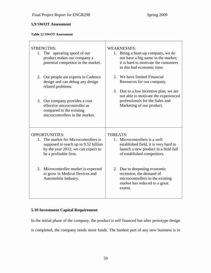
5.9 SWOT Assessment Table 12 SWOT Assessment STRENGTHS:
1. The operating speed of our product makes our company a potential competitor in the market.
2. Our people are experts in Cadence design and can debug any design related problems.
3. Our company provides a cost effective microcontroller as compared to the existing microcontrollers in the market.
WEAKNESSES:
1. Being a Start-up company, we do not have a big name in the market; it is hard to motivate the customers in this bad economic time.
2. We have limited Financial
Resources for our company.
3. Due to a low incentive plan, we are not able to motivate the experienced professionals for the Sales and Marketing of our product.
OPPORTUNITIES:
1. The market for Microcontrollers is supposed to reach up to 9.52 billion by the year 2012; we can expect to be a profitable firm.
2. Microcontroller market is expected to grow in Medical Devices and Automobile Industry.
THREATS:
1. Microcontrollers is a well established field, it is very hard to launch a new product in a field full of established competitors.
2. Due to deepening economic recession, the demand of microcontrollers in the existing market has reduced to a great extent.
5.10 Investment Capital Requirement In the initial phase of the company, the product is self financed but after prototype design
is completed, the company needs more funds. The hardest part of any new business is to
Final Project Report for ENGR298 Spring 2009
60
find an investor for your business. The possible sources of funds are banks and small
investors. To satisfy resource requirement, it is essential to approach Venture Capitalist
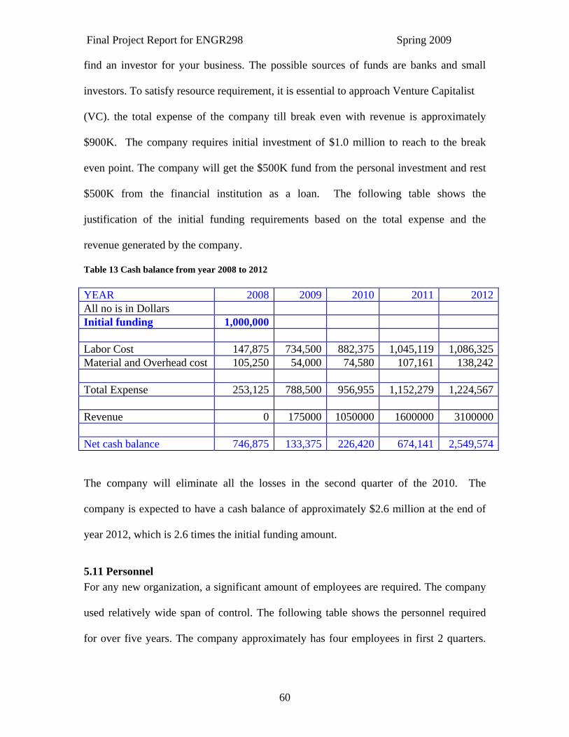
(VC). the total expense of the company till break even with revenue is approximately
$900K. The company requires initial investment of $1.0 million to reach to the break
even point. The company will get the $500K fund from the personal investment and rest
$500K from the financial institution as a loan. The following table shows the
justification of the initial funding requirements based on the total expense and the
revenue generated by the company.
Table 13 Cash balance from year 2008 to 2012 YEAR 2008 2009 2010 2011 2012All no is in Dollars Initial funding 1,000,000 Labor Cost 147,875 734,500 882,375 1,045,119 1,086,325Material and Overhead cost 105,250 54,000 74,580 107,161 138,242 Total Expense 253,125 788,500 956,955 1,152,279 1,224,567 Revenue 0 175000 1050000 1600000 3100000 Net cash balance 746,875 133,375 226,420 674,141 2,549,574
The company will eliminate all the losses in the second quarter of the 2010. The
company is expected to have a cash balance of approximately $2.6 million at the end of
year 2012, which is 2.6 times the initial funding amount.
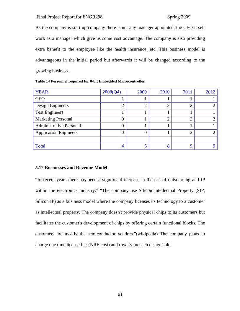
5.11 Personnel For any new organization, a significant amount of employees are required. The company
used relatively wide span of control. The following table shows the personnel required
for over five years. The company approximately has four employees in first 2 quarters.
Final Project Report for ENGR298 Spring 2009
61
As the company is start up company there is not any manager appointed, the CEO it self
work as a manager which give us some cost advantage. The company is also providing
extra benefit to the employee like the health insurance, etc. This business model is
advantageous in the initial period but afterwards it will be changed according to the
growing business.
Table 14 Personnel required for 8-bit Embedded Microcontroller YEAR 2008(Q4) 2009 2010 2011 2012CEO 1 1 1 1 1Design Engineers 2 2 2 2 2Test Engineers 1 1 1 1 1Marketing Personal 0 1 2 2 2Administrative Personal 0 1 1 1 1Application Engineers 0 0 1 2 2 Total 4 6 8 9 9
5.12 Businesses and Revenue Model “In recent years there has been a significant increase in the use of outsourcing and IP
within the electronics industry.” “The company use Silicon Intellectual Property (SIP,
Silicon IP) as a business model where the company licenses its technology to a customer
as intellectual property. The company doesn't provide physical chips to its customers but
facilitates the customer's development of chips by offering certain functional blocks. The
customers are mostly the semiconductor vendors.”(wikipedia) The company plans to
charge one time license fees(NRE cost) and royalty on each design sold.
Final Project Report for ENGR298 Spring 2009
62
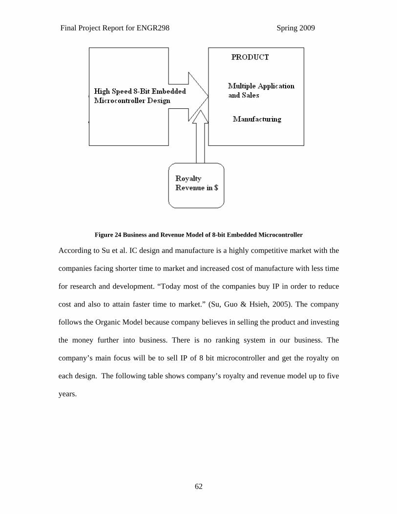
Figure 24 Business and Revenue Model of 8-bit Embedded Microcontroller According to Su et al. IC design and manufacture is a highly competitive market with the
companies facing shorter time to market and increased cost of manufacture with less time
for research and development. “Today most of the companies buy IP in order to reduce
cost and also to attain faster time to market.” (Su, Guo & Hsieh, 2005). The company
follows the Organic Model because company believes in selling the product and investing
the money further into business. There is no ranking system in our business. The
company’s main focus will be to sell IP of 8 bit microcontroller and get the royalty on
each design. The following table shows company’s royalty and revenue model up to five
years.
Final Project Report for ENGR298 Spring 2009
63
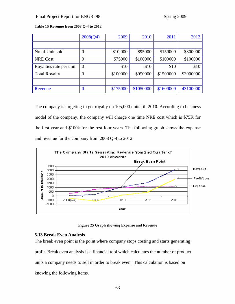
Table 15 Revenue from 2008 Q-4 to 2012 2008(Q4) 2009 2010 2011 2012 No of Unit sold 0 $10,000 $95000 $150000 $300000NRE Cost 0 $75000 $100000 $100000 $100000Royalties rate per unit 0 $10 $10 $10 $10Total Royalty 0 $100000 $950000 $1500000 $3000000 Revenue 0 $175000 $1050000 $1600000 43100000
The company is targeting to get royalty on 105,000 units till 2010. According to business
model of the company, the company will charge one time NRE cost which is $75K for
the first year and $100k for the rest four years. The following graph shows the expense
and revenue for the company from 2008 Q-4 to 2012.
Figure 25 Graph showing Expense and Revenue
5.13 Break Even Analysis The break even point is the point where company stops costing and starts generating
profit. Break even analysis is a financial tool which calculates the number of product
units a company needs to sell in order to break even. This calculation is based on
knowing the following items.
Final Project Report for ENGR298 Spring 2009
64
• The fixed costs of the company
• The variable costs for a product
• The selling price for a product
The fixed costs of the company are defined as the sum of all the costs needed to
produce the first unit of product. Fixed costs of a company include taxes, building lease,
insurance and building depreciation. Variable costs include product material costs and
utility costs. As the volume of production increases, there is a corresponding rise in
material and utility costs (Daniel, 2002).
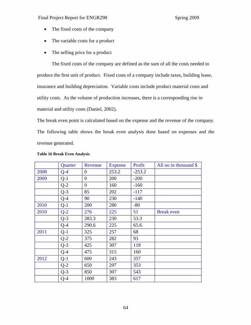
The break even point is calculated based on the expense and the revenue of the company.
The following table shows the break even analysis done based on expenses and the
revenue generated.
Table 16 Break Even Analysis Quarter Revenue Expense Profit All no in thousand $ 2008 Q-4 0 253.2 -253.2 2009 Q-1 0 200 -200 Q-2 0 160 -160 Q-3 85 202 -117 Q-4 90 230 -140 2010 Q-1 200 280 -80 2010 Q-2 276 225 51 Break even Q-3 283.3 230 53.3 Q-4 290.6 225 65.6 2011 Q-1 325 257 68 Q-2 375 282 93 Q-3 425 307 118 Q-4 475 315 160 2012 Q-1 600 243 357 Q-2 650 297 353 Q-3 850 307 543 Q-4 1000 383 617
Final Project Report for ENGR298 Spring 2009
65
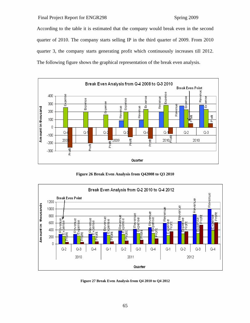
According to the table it is estimated that the company would break even in the second
quarter of 2010. The company starts selling IP in the third quarter of 2009. From 2010
quarter 3, the company starts generating profit which continuously increases till 2012.
The following figure shows the graphical representation of the break even analysis.
Figure 26 Break Even Analysis from Q42008 to Q3 2010
Figure 27 Break Even Analysis from Q4 2010 to Q4 2012

Final Project Report for ENGR298 Spring 2009
66
“In finance, rate of return (ROR), also known as return on investment (ROI), rate of
profit or sometimes just return, is the ratio of money gained or lost (realized or
unrealized) on an investment relative to the amount of money invested. The amount of
money gained or lost may be referred to as interest, profit/loss, gain/loss, or net
income/loss. The money invested may be referred to as the asset, capital, principal, or the
cost basis of the investment. ROI is usually expressed as a percentage rather than a
fraction.” (wikipedia)
The Return on investment = (Cumulative Profit – Profit)/Initial Investment*100
= (1528.7/1000)*100
= 152.87%
The return on investment for the company after five years is approximately 152.87%. The
above ROI done based on customer market. The targeted customer of the company is
consumer appliance manufacturer. The need of consumer appliances is increases day by
day so therefore company expects that the revenue growth will be increases compared
with the estimated one after five years.
5.14 Strategic Alliance /Partner The company will decide to participate in Strategic Alliance in order to attract more
customers and become more profitable.
5.15 Profit and Loss Statement The profit and loss statement is very important financial statement for any start up
company to show their investor whether company is making money or loosing money.
The profit of the product depends on the revenue and expense. The Revenue of product
depends on the royally and the selling price. The total initial investment of the project is
$1.0 million. Total expense of the project without revenue is approximately $4 million.
Final Project Report for ENGR298 Spring 2009
67
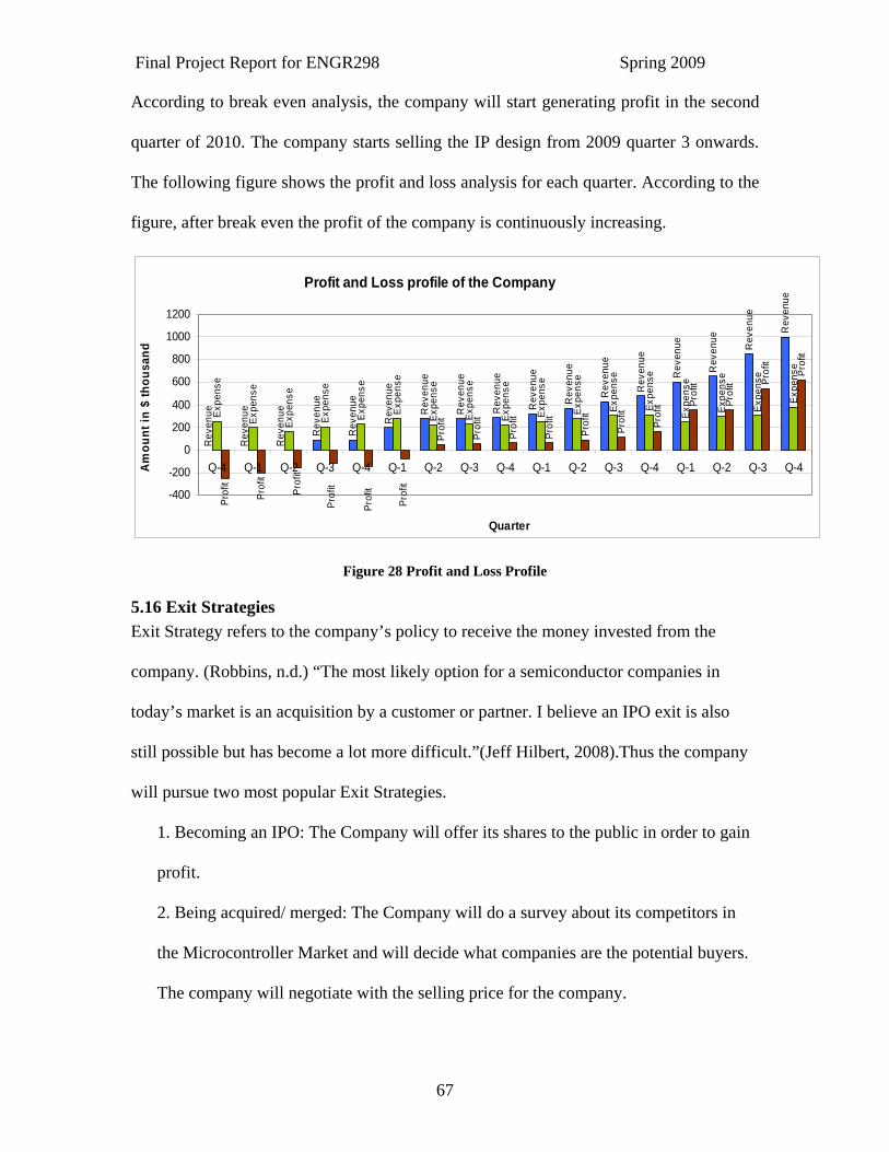
According to break even analysis, the company will start generating profit in the second
quarter of 2010. The company starts selling the IP design from 2009 quarter 3 onwards.
The following figure shows the profit and loss analysis for each quarter. According to the
figure, after break even the profit of the company is continuously increasing.
Profit and Loss profile of the Company
Rev
enue
Rev
enue
Rev
enue
Rev
enue
Rev
enue
Rev
enue
Rev
enue
Rev
enue
Rev
enue
Rev
enue
Rev
enue
Rev
enue
Rev
enue
Rev
enue
Rev
enue
Rev
enue
Rev
enue
Expe
nse
Expe
nse
Expe
nse
Expe
nse
Expe
nse
Expe
nse
Expe
nse
Expe
nse
Expe
nse
Expe
nse
Expe
nse
Expe
nse
Expe
nse
Expe
nse
Expe
nse
Expe
nse
Expe
nse
Prof
it
Prof
it
Prof
it
Prof
it
Prof
it
Prof
it
Prof
it
Prof
it
Prof
it
Prof
it Prof
it
Prof
it Prof
it
Prof
it
Prof
it
Prof
it
Prof
it
-400
-200
0
200
400
600
800
1000
1200
Q-4 Q-1 Q-2 Q-3 Q-4 Q-1 Q-2 Q-3 Q-4 Q-1 Q-2 Q-3 Q-4 Q-1 Q-2 Q-3 Q-4
Quarter
Am
ount
in $
thou
sand
Figure 28 Profit and Loss Profile
5.16 Exit Strategies Exit Strategy refers to the company’s policy to receive the money invested from the
company. (Robbins, n.d.) “The most likely option for a semiconductor companies in
today’s market is an acquisition by a customer or partner. I believe an IPO exit is also
still possible but has become a lot more difficult.”(Jeff Hilbert, 2008).Thus the company
will pursue two most popular Exit Strategies.
1. Becoming an IPO: The Company will offer its shares to the public in order to gain
profit.
2. Being acquired/ merged: The Company will do a survey about its competitors in
the Microcontroller Market and will decide what companies are the potential buyers.
The company will negotiate with the selling price for the company.

Final Project Report for ENGR298 Spring 2009
68
The other option for the company is to consider being merged with another company
with good understanding in order to have an edge in the market.
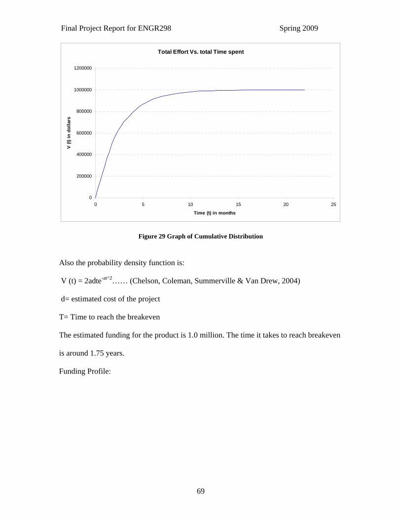
5.17 Norden Rayleigh Profile The Rayleigh’s cumulative distribution derived from the research done by Norden, Lee
and other people is given as:
V (t) = d (1-e-at^2) (Chelson, Coleman, Summerville & Van Drew, 2004)
Where V (t) = Total Effort spent on the Project
d= scale factor
a= shape parameter
T= Time to reach the breakeven
The estimated funding for the product is 1.0 million. The time it takes to reach breakeven
is around 1.75 years.
Cumulative Distribution:
Final Project Report for ENGR298 Spring 2009
69
Total Effort Vs. total Time spent
0
200000
400000
600000
800000
1000000
1200000
0 5 10 15 20 25
Time (t) in months
V (t)
in d
olla
rs
Figure 29 Graph of Cumulative Distribution
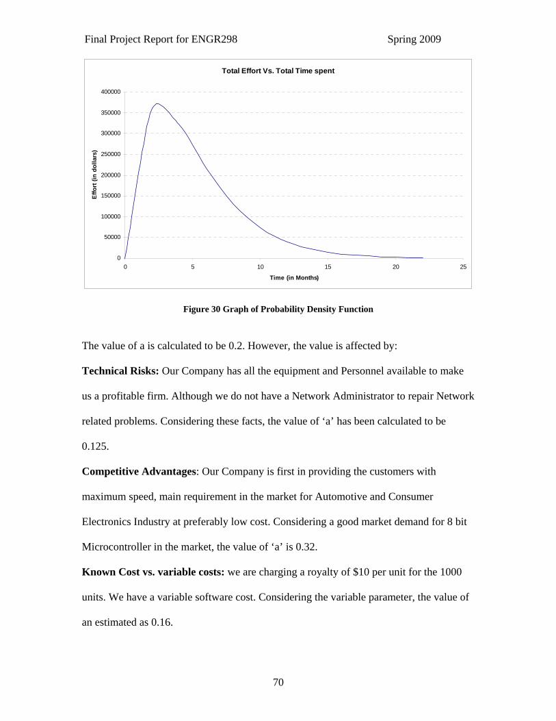
Also the probability density function is:
V (t) = 2adte-at^2…… (Chelson, Coleman, Summerville & Van Drew, 2004)
d= estimated cost of the project
T= Time to reach the breakeven
The estimated funding for the product is 1.0 million. The time it takes to reach breakeven
is around 1.75 years.
Funding Profile:
Final Project Report for ENGR298 Spring 2009
70
Total Effort Vs. Total Time spent
0
50000
100000
150000
200000
250000
300000
350000
400000
0 5 10 15 20 25
Time (in Months)
Effo
rt (i
n do
llars
)
Figure 30 Graph of Probability Density Function
The value of a is calculated to be 0.2. However, the value is affected by:
Technical Risks: Our Company has all the equipment and Personnel available to make
us a profitable firm. Although we do not have a Network Administrator to repair Network
related problems. Considering these facts, the value of ‘a’ has been calculated to be
0.125.
Competitive Advantages: Our Company is first in providing the customers with
maximum speed, main requirement in the market for Automotive and Consumer
Electronics Industry at preferably low cost. Considering a good market demand for 8 bit
Microcontroller in the market, the value of ‘a’ is 0.32.
Known Cost vs. variable costs: we are charging a royalty of $10 per unit for the 1000
units. We have a variable software cost. Considering the variable parameter, the value of
an estimated as 0.16.
Final Project Report for ENGR298 Spring 2009
71
5.18 Future of 8-Bit Embedded Microcontroller Our company is unique in designing 8-bit Microcontroller; main focus is to gain the
maximum profit. The 8 bit microcontroller is suitable for the higher performance, reliable
and flexible for the growing semiconductor market. Our 8 bit microcontroller is used for
various applications such as in consumer appliances, automotive industries, medical
instruments and also for the security systems.
“The worldwide microcontroller (MCU) units shipped between 2004 and 2009 will
increase at a Compound Annual Growth Rate (CAGR) of 10.3%”. (www.in-state.
com)According to ST Microelectronics “The 8-bit MCU market, currently worth about
$5 billion, is expected to continue showing healthy growth, with unit shipments expected
to exceed 6500M in 2011 compared to 4400M in 2007. In automotive applications alone,
for example, unit growth between 2007 and 2013 is expected to be around 40%.
However, a key feature of the 8-bit MCU market is the pressure to reduce the cost of
implementing solutions and the STM8 platform has been specifically designed to provide
increased performance at significantly lower total system cost.” (SCOTTSDALE, Ariz.,
September 19, 2005). Based on the market analysis and current market the following
figure shows the growth rate of microcontrollers.
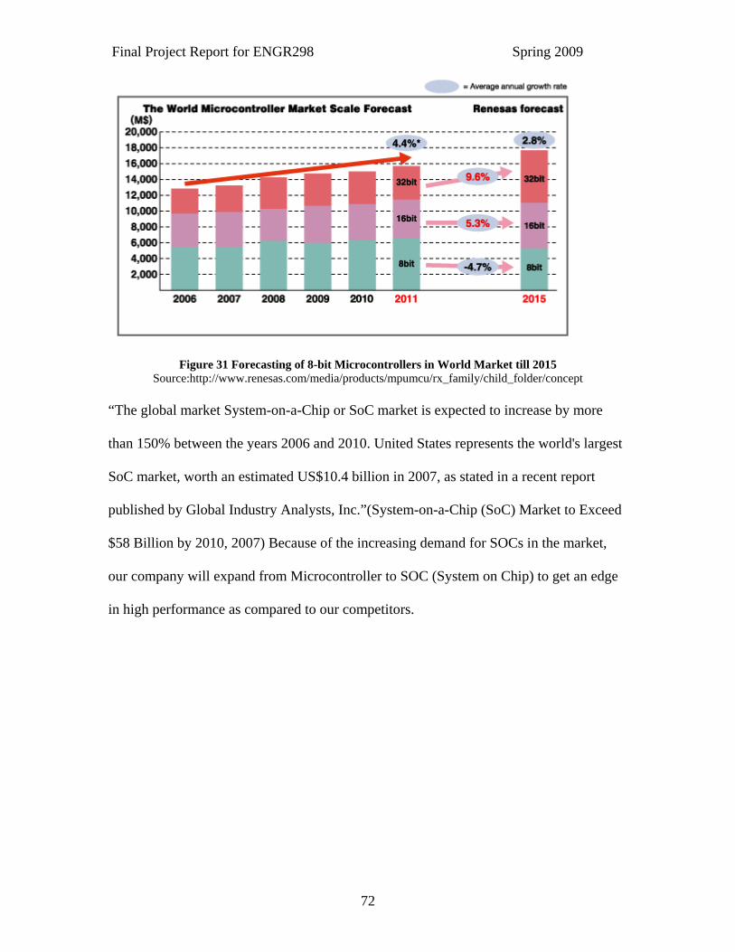
Final Project Report for ENGR298 Spring 2009
72
Figure 31 Forecasting of 8-bit Microcontrollers in World Market till 2015 Source:http://www.renesas.com/media/products/mpumcu/rx_family/child_folder/concept
“The global market System-on-a-Chip or SoC market is expected to increase by more
than 150% between the years 2006 and 2010. United States represents the world's largest
SoC market, worth an estimated US$10.4 billion in 2007, as stated in a recent report
published by Global Industry Analysts, Inc.”(System-on-a-Chip (SoC) Market to Exceed
$58 Billion by 2010, 2007) Because of the increasing demand for SOCs in the market,
our company will expand from Microcontroller to SOC (System on Chip) to get an edge
in high performance as compared to our competitors.

Final Project Report for ENGR298 Spring 2009
73
Conclusion The IP design of an 8-bit Embedded Microcontroller with the pipelined architecture is
capable of providing 1.5GHz performance speed. The market requires flexible, low cost,
high performance and compact design for the special customers like consumer electronics
and automobile industries. The 8-bit Embedded Microcontroller provides all the unique
features to the customer at one third cost of the exiting high speed Microcontrollers
available in the market.
The company follows simple IP based business model with the initial NRE cost of $75K
and is charging fixed royalty rate of $10 per unit. The company will start generating
profit from 2010 onwards with positive cash flow and expected ROI is 152.8%.
According to the market research and economic analysis, the company will gain
substantial growth in the next few years. The Product has fast production time, resulting
in reduced time to market, and will prove to be a Profitable business.
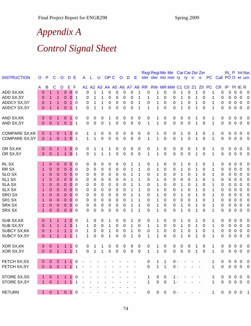
Final Project Report for ENGR298 Spring 2009
74
Appendix A
Control Signal Sheet
INSTRUCTION O P C O D E A L U OP C O D E
Register
Register
Memo
Memor
Carry
Carry
Zero
Zero PC Call
IN_PO
PO
Inter
Return
A B C D E F A1 A2 A3 A4 A5 A6 A7 A8 RR RW MR MW C1 C0 Z1 Z0 PC CR IP PI IE R ADD SX,KK 0 1 1 0 0 0 0 1 1 0 0 0 0 1 0 1 0 0 1 0 1 0 1 0 0 0 0 0ADD SX,SY 0 1 1 0 0 1 0 1 1 0 0 0 0 1 1 1 0 0 1 0 1 0 1 0 0 0 0 0ADDCY SX,SY 0 1 1 0 1 0 0 1 1 0 0 0 0 1 0 1 0 0 1 0 1 0 1 0 0 0 0 0ADDCY SX,SY 0 1 1 0 1 1 0 1 1 0 0 0 0 1 1 1 0 0 1 0 1 0 1 0 0 0 0 0 AND SX,KK 0 0 1 0 1 0 0 0 0 1 0 0 0 0 0 1 0 0 0 0 1 0 1 0 0 0 0 0AND SX,SY 0 0 1 0 1 1 0 0 0 1 0 0 0 0 1 1 0 0 0 0 1 0 1 0 0 0 0 0 COMPARE SX,KK 0 1 0 1 0 0 1 1 0 0 0 0 0 0 0 1 0 0 1 0 1 0 1 0 0 0 0 0COMPARE SX,SY 0 1 0 1 0 1 1 1 0 0 0 0 0 0 1 1 0 0 1 0 1 0 1 0 0 0 0 0 OR SX,KK 0 0 1 1 0 0 0 1 1 1 0 0 0 0 0 1 0 0 0 0 1 0 1 0 0 0 0 0OR SX,SY 0 0 1 1 0 1 0 1 1 1 0 0 0 0 1 1 0 0 0 0 1 0 1 0 0 0 0 0 RL SX 1 0 0 0 0 0 0 0 0 0 0 0 1 1 0 1 0 0 1 0 1 0 1 0 0 0 0 0RR SX 1 0 0 0 0 0 0 0 0 0 0 0 1 1 0 1 0 0 1 0 1 0 1 0 0 0 0 0SLO SX 1 0 0 0 0 0 0 0 0 0 0 0 1 1 0 1 0 0 1 0 1 0 1 0 0 0 0 0SL1 SX 1 0 0 0 0 0 0 0 0 0 0 0 1 1 0 1 0 0 0 0 1 0 1 0 0 0 0 0SLA SX 1 0 0 0 0 0 0 0 0 0 0 0 1 1 0 1 0 0 1 0 1 0 1 0 0 0 0 0SLX SX 1 0 0 0 0 0 0 0 0 0 0 0 1 1 0 1 0 0 1 0 1 0 1 0 0 0 0 0SRO SX 1 0 0 0 0 0 0 0 0 0 0 0 1 1 0 1 0 0 1 0 1 0 1 0 0 0 0 0SR1 SX 1 0 0 0 0 0 0 0 0 0 0 0 1 1 0 1 0 0 0 0 1 0 1 0 0 0 0 0SRA SX 1 0 0 0 0 0 0 0 0 0 0 0 1 1 0 1 0 0 1 0 1 0 1 0 0 0 0 0SRX SX 1 0 0 0 0 0 0 0 0 0 0 0 1 1 0 1 0 0 1 0 1 0 1 0 0 0 0 0 SUB SX,KK 0 1 1 1 0 0 1 0 0 1 0 0 1 0 0 1 0 0 1 0 1 0 1 0 0 0 0 0SUB SX,SY 0 1 1 1 0 1 1 0 0 1 0 0 1 0 1 1 0 0 1 0 1 0 1 0 0 0 0 0SUBCY SX,KK 0 1 1 1 1 0 1 0 0 1 0 0 1 0 0 1 0 0 1 0 1 0 1 0 0 0 0 0SUBCY SX,SY 0 1 1 1 1 1 1 0 0 1 0 0 1 0 1 1 0 0 1 0 1 0 1 0 0 0 0 0 XOR SX,KK 0 0 1 1 1 0 0 1 1 0 0 0 0 0 0 1 0 0 0 0 1 0 1 0 0 0 0 0XOR SX,SY 0 0 1 1 1 1 0 1 1 0 0 0 0 0 1 1 0 0 0 0 1 0 1 0 0 0 0 0 FETCH SX,SS 0 0 0 1 1 0 - - - - - - - - 0 1 1 0 - - - - 1 0 0 0 0 0FETCH SX,SY 0 0 0 1 1 1 - - - - - - - - 0 1 1 0 - - - - 1 0 0 0 0 0 - - - - - - - - STORE SX,SS 1 0 1 1 1 0 - - - - - - - - 1 0 0 1 - - - - 1 0 0 0 0 0STORE SX,SY 1 0 1 1 1 1 - - - - - - - - 1 0 0 1 - - - - 1 0 0 0 0 0 - - - - - - - - RETURN 1 0 1 0 1 0 - - - - - - - - 0 0 0 0 - - - - 1 0 0 0 0 1
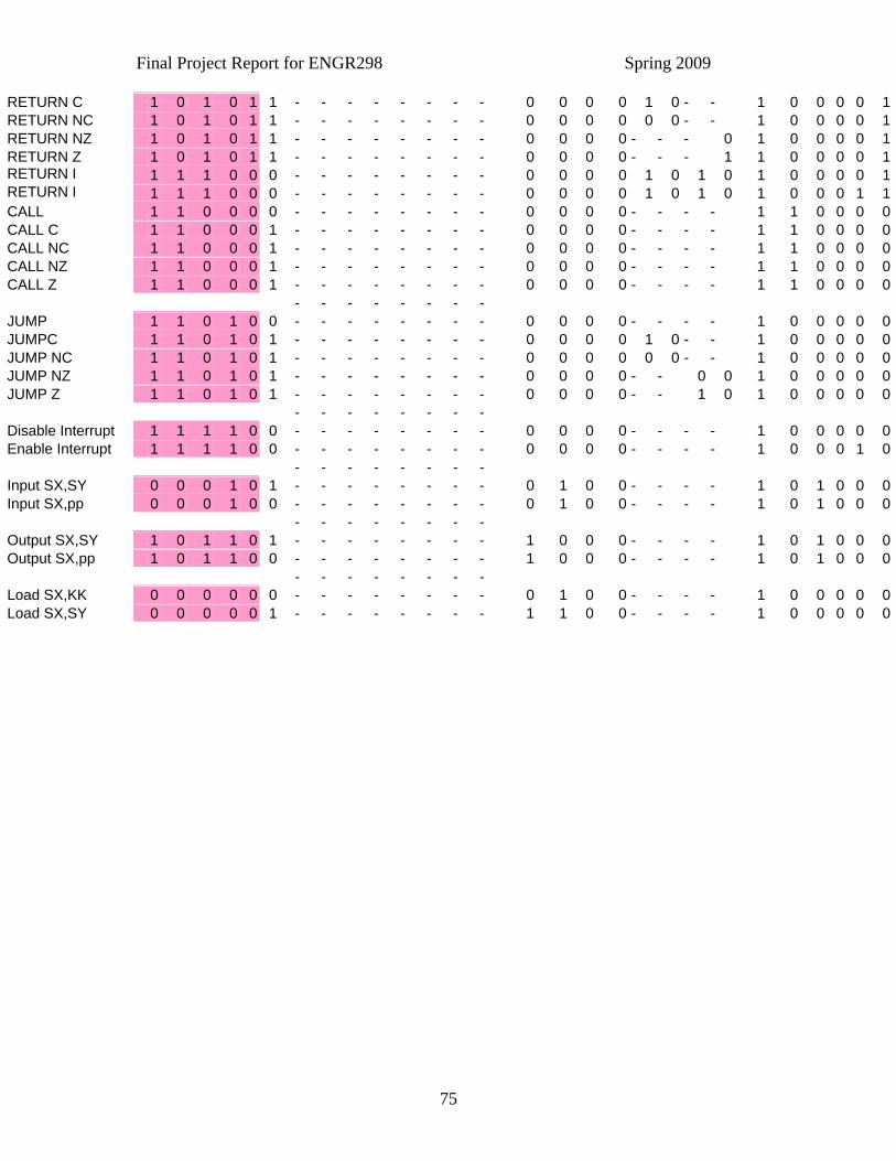
Final Project Report for ENGR298 Spring 2009
75
RETURN C 1 0 1 0 1 1 - - - - - - - - 0 0 0 0 1 0 - - 1 0 0 0 0 1RETURN NC 1 0 1 0 1 1 - - - - - - - - 0 0 0 0 0 0 - - 1 0 0 0 0 1RETURN NZ 1 0 1 0 1 1 - - - - - - - - 0 0 0 0 - - - 0 1 0 0 0 0 1RETURN Z 1 0 1 0 1 1 - - - - - - - - 0 0 0 0 - - - 1 1 0 0 0 0 1RETURN I 1 1 1 0 0 0 - - - - - - - - 0 0 0 0 1 0 1 0 1 0 0 0 0 1RETURN I 1 1 1 0 0 0 - - - - - - - - 0 0 0 0 1 0 1 0 1 0 0 0 1 1CALL 1 1 0 0 0 0 - - - - - - - - 0 0 0 0 - - - - 1 1 0 0 0 0CALL C 1 1 0 0 0 1 - - - - - - - - 0 0 0 0 - - - - 1 1 0 0 0 0CALL NC 1 1 0 0 0 1 - - - - - - - - 0 0 0 0 - - - - 1 1 0 0 0 0CALL NZ 1 1 0 0 0 1 - - - - - - - - 0 0 0 0 - - - - 1 1 0 0 0 0CALL Z 1 1 0 0 0 1 - - - - - - - - 0 0 0 0 - - - - 1 1 0 0 0 0 - - - - - - - - JUMP 1 1 0 1 0 0 - - - - - - - - 0 0 0 0 - - - - 1 0 0 0 0 0JUMPC 1 1 0 1 0 1 - - - - - - - - 0 0 0 0 1 0 - - 1 0 0 0 0 0JUMP NC 1 1 0 1 0 1 - - - - - - - - 0 0 0 0 0 0 - - 1 0 0 0 0 0JUMP NZ 1 1 0 1 0 1 - - - - - - - - 0 0 0 0 - - 0 0 1 0 0 0 0 0JUMP Z 1 1 0 1 0 1 - - - - - - - - 0 0 0 0 - - 1 0 1 0 0 0 0 0 - - - - - - - - Disable Interrupt 1 1 1 1 0 0 - - - - - - - - 0 0 0 0 - - - - 1 0 0 0 0 0Enable Interrupt 1 1 1 1 0 0 - - - - - - - - 0 0 0 0 - - - - 1 0 0 0 1 0 - - - - - - - - Input SX,SY 0 0 0 1 0 1 - - - - - - - - 0 1 0 0 - - - - 1 0 1 0 0 0Input SX,pp 0 0 0 1 0 0 - - - - - - - - 0 1 0 0 - - - - 1 0 1 0 0 0 - - - - - - - - Output SX,SY 1 0 1 1 0 1 - - - - - - - - 1 0 0 0 - - - - 1 0 1 0 0 0Output SX,pp 1 0 1 1 0 0 - - - - - - - - 1 0 0 0 - - - - 1 0 1 0 0 0 - - - - - - - - Load SX,KK 0 0 0 0 0 0 - - - - - - - - 0 1 0 0 - - - - 1 0 0 0 0 0Load SX,SY 0 0 0 0 0 1 - - - - - - - - 1 1 0 0 - - - - 1 0 0 0 0 0

Final Project Report for ENGR298 Spring 2009
76
Appendix B
Logic Reduction of Control Signals #CONTROL LOGIC UNIT
.i 6
.o 22
.p 22
000001 0000000010000000000000
11000- 0000000000000000010000
111100 0000000000000000100010
011--1 0000000010000000000000
01-101 0000000010000000000000
00010- 0000000000000000001000
111000 0000000000001010100001
-011-1 0000000010000000000000
10101- 0000000000000000100001
0-110- 0001000000000000000000

Final Project Report for ENGR298 Spring 2009
77
0-1-11 0000000010000000000000
100000 0000001101001010100000
10111- 0000000010010000100000
110-0- 0000000000000000100000
00011‐ 0000000001100000100000
10110‐ 0000000010000000101000
00101‐ 0001000001000010100000
000‐0‐ 0000000001000000100000
01010‐ 1100000001001010100000
0011‐‐ 0110000001000010100000
0110‐‐ 0110000101001010100000
0111‐‐ 1001001001001010100000
.e
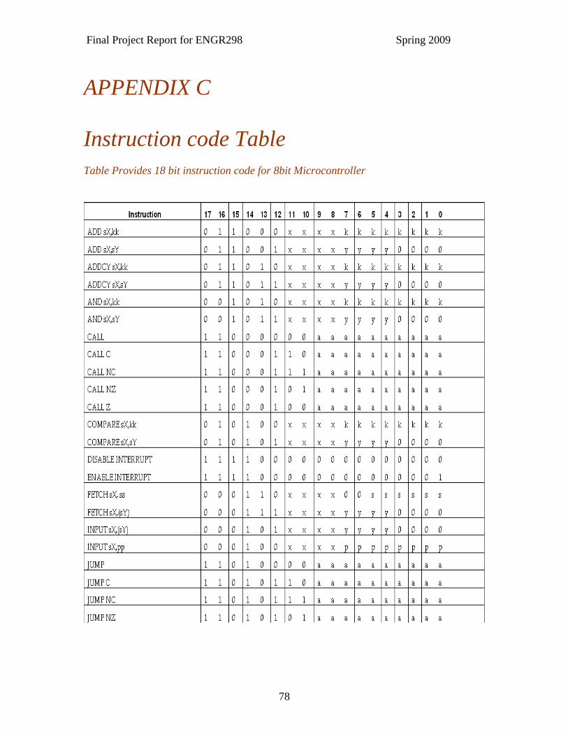
Final Project Report for ENGR298 Spring 2009
78
APPENDIX C Instruction code Table Table Provides 18 bit instruction code for 8bit Microcontroller
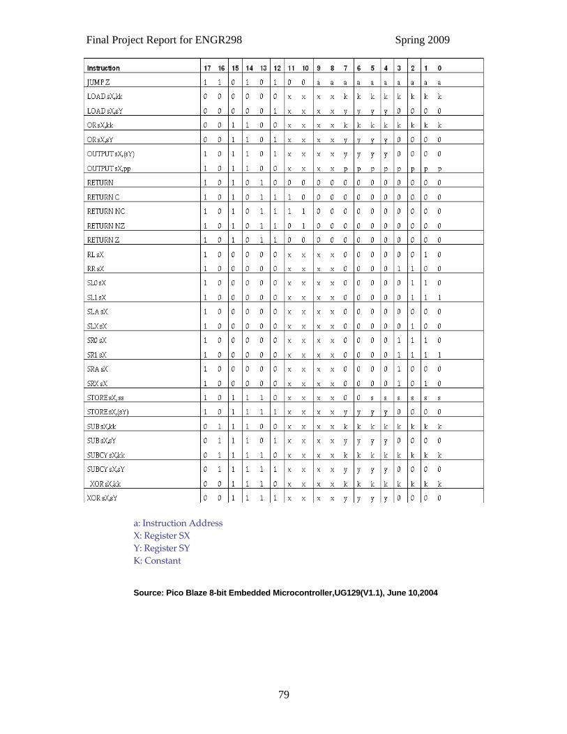
Final Project Report for ENGR298 Spring 2009
79
a: Instruction Address X: Register SX Y: Register SY K: Constant
Source: Pico Blaze 8-bit Embedded Microcontroller,UG129(V1.1), June 10,2004
Final Project Report for ENGR298 Spring 2009
80
REFERENCES A. Castillo Atoche, J.Azquez Castillo, & V. Sanchez Huerta (April 2006)
Implementation of MIPS control with FPGA Using Remote Manipulations. IEEE Explore, 26-28
Appliance Magazine (April 2009), Factory Unit Shipment Statistic for the month of January 2009, ApplianceMagazine.com Archide, R., (November, 2006), The Micro Blaze V5.0 Soft Core Processor: Optimize for Performance, Embedded Magazine, 18-21
Augesto, A., Matos, R., & Moura, S., (2006) Advantages and Disadvantages of
application Oriented System Design in Embedded System Design, IEEE Explore Babcock, D., Morse, L. (Third Ed.). (2002). Managing Engineering and Technology.
Prentice Hall, Inc Baraniceki, R., Janiszewki, I., & Siekierska, K., (October, 1999) A Reusable Microcontroller Core Design, IEEE Explore, 14-19
Colin Holland, (April 6, 2007), Altera attacks custom IC market to provide
organic growth, EE times Europe, http://www.eetimes.eu/199900732
Dhir, A. & Mousavi, S., (March 16, 2000), High performance Spartan-2 8 bit Microcontroller Solution, Xillinx, 1-14 Website: http://www.xilinx.com/support/documentation/white_papers/wp114.pdf
Dorosti, J. San Jose State University, Class notes of ENGR 203
Duckworth, J., WPI, Embedded Microprocessors. Retrieved April16, 2009 from Web site:http://ece.wpi.edu/~rjduck/VHDL%20micros.pdf Ed Sperling (18th April 2008), Hot Market for 8-Bit Microcontroller, EEcatalog Hilbert, J. (2008), MEMS, Micro fluidics and Microsystems Executive Review.
Retrieved May 8, 2009 from Web site: http://www.memsinvestorjournal.com
Jacome, M., (2000), Design challenges for New Application Specific Processors, IEEE Design &Test Computer, 40-50
Jean Anne Booth (4th January 2008), Consolidating the MCU market around the ARM Architecture, Embedded.com
Final Project Report for ENGR298 Spring 2009
81
Ken Chapman (May, 2007), Xilinx User Community Forum, Web site: http:// forums.xilinx.com/xlnx/board/message?board.id=PicoBlaze&thread.id=24
Kundu, S., Pal, A., Roy, S., (June 2007). Retrieved March 4, 2008 from Website:
http://www.facweb.iitkgp.ernet.in/~apal/files/June%2014%20&%2015. Le, M. (2004), 8 bit Microcontrollers: still going. Retrieved April 13, 2009 from Web site: http://www.eetimes.com Munich, (2007). Automotive applications to drive microcontroller market. Retrieved
April 14, 2009 from Web site:http://eetimes.eu/germany/202101848
Ramanan, R., (2004). Connectivity and Cost Propel the Microcontroller Market. Retrieved March 2, 2009 from Web site: http://ww.frost.com/prod/
Renesas Technology Boosts Throughput of Microcontrollers in H8SX 32-Bit CISC
Family, (Dec 2007), Retrieved January 3, 2009 from Web site: http://www.embedded-computing.com/news/db/
Robbins. (n.d), Exit Strategies for Business. Retrieved April13, 2009 from Website: http://www.entrepreneur.com/management/operations Su Yea-Huey; Guo Ruey-Shan; Hsieh Wen-Yuan. (2005, August). Historically Explore
on the Patterns of Business Model for Silicon Intellectual Property (ip) Providers in the Semiconductor Industry. Technology Management a Unifying Discipline for Melting Boundaries, p.447-458
System-on-a-Chip (SoC) Market to Exceed $58 Billion by 2010 (October 15, 2007) Retrieved April 15, 2009 from Web site: http://www.electronics.ca/presscenter/ Scottsdale, A., (September, 2005). Strong Growth to continue MCU market. http://www.instat.com/press.asp?ID=1445&sku=IN0502457SI Xilinx Micro Blaze Microcontroller Reference Design User Guide. (September 2005).
Xillinx Pico Blaze 8bit Embedded Microcontroller. (June10, 2004), UG 129,V1.1 Source:http://www.renesas.com/media/products/mpumcu/rx_family/child_folder/concept http://www.luminarymicro.com/about_luminary/market_background.html) http://eetimes.eu/germany/202101848