Embed Size (px)
Citation preview

High-Resolution Organic Light-Emitting Diodes Patterned viaContact PrintingJinhai Li, Lisong Xu, Ching W. Tang, and Alexander A. Shestopalov*
Department of Chemical Engineering, University of Rochester, Rochester, New York 14627, United States
*S Supporting Information
ABSTRACT: In this study, we report a contact printing technique that usespolyurethane-acrylate (PUA) polymers as the printing stamps to pattern electro-luminescent layers of organic light emitting diodes (OLEDs). We demonstrate thatelectroluminescent thin films can be printed with high uniformity and resolution. We alsoshow that the performance of the printed devices can be improved via postprintingthermal annealing, and that the external quantum efficiency of the printed devices iscomparable with the efficiency of the vacuum-deposited OLEDs. Our results suggest thatthe PUA-based contact printing can be used as an alternative to the traditional shadowmask deposition, permitting manufacturing of OLED displays with the resolution up tothe diffraction limit of visible-light emission.
KEYWORDS: contact printing, polyurethane acrylate, thin-film patterning, organic light emitting diodes, high-resolution printing
■ INTRODUCTION
Contact printing is a patterning method that relies on theinterfacial material transfer from an elastic stamp to a hard orsoft substrate. Because of its simplicity, contact printing is oftenconsidered as the method of choice for additive micro- andnanoscale manufacturing of multilayered thin-film devices.1−6
Several studies have demonstrated successful thin filmpatterning of electronic components using simple interfacialmaterial transfer with elastic polydimethylsiloxane (PDMS)stamps. Despite its many advantages, a few limitations of thePDMS-based printing remain, specifically (i) relatively largefeature sizes (tens of micrometers) due to the distortion anddeformation of the low modulus PDMS stamps,7,8 (ii) limitedcontrol over the interfacial adhesion due to the constanthydrophobic nature of PDMS,9−11 and (iii) reduced efficiencyof the fabricated devices due to the low quality of the printedinterfacial contacts.4,12 In addition, thin film delamination/deposition mechanics in the PDMS-based printing is typicallyregulated by the rate-dependent effects of viscoelastic PDMSstamps.13−17 Such rate-dependent modulation of thin filmadhesion requires careful optimization and control of thestamping velocity for each new printing material, and so far ithas been primarily used for printing large 50−100 μm features.Traditional OLED microdisplays use large-area white pixels
with patterned color filters to produce RGB subpixels. Thefilters reduce light transmission by ∼80%, lowering efficiency.Direct deposition of RGB emitters via shadow mask depositionthrough the standard fine metal mask (FMM) directly depositsand aligns individual color pixels, avoiding the transmissionloss. However, FMM-based patterning has a limited resolution(>10 μm) due to the material diffusion in the gap between the
mask and the substrate.18,19 Because contact printing directlytransfers materials between interfaces, it avoids the diffusivelimitation of the shadow mask deposition. Beyond resolution,contact printing offers two other major advantages: (1) FMMsare very difficult to scale up to large and curvilinear substratesand they are more expensive to replace compared to simplepolymeric molds, and (2) shadow-masks block a large fractionof evaporated material and require frequent cleaning, leading tosignificant waste of organic semiconducting materials and highproduction cost. Previously, the PDMS-based printing was usedto structure OLED components. For example, spin-coatedorganic electroluminescent layers were directly transferred fromthe PDMS stamp to create functional multilayered OLEDdevices.20,21 These studies demonstrated that different emitterscan be used to create continuous OLEDs20 and patternedOLED chips with ∼150 μm electroluminescent pixels.21
However, the efficiency of the printed devices was notcompared to the standard vacuum-deposited OLEDs, and itwas noted, that the poor integrity of the printed films can leadto a low device performance.20 In another study, a flat thinPDMS layer supported on the rigid backplane was used toindirectly pattern 12 μm × 40 μm OLED pixels. It wasdemonstrated, that the JV characteristics of the printed andspin-coated devices with continuous emitting layers arecomparable, but no comparison between the patterned devicesand devices fabricated in vacuum was provided.22 Other worksin this area included patterning of >10 μm OLED pixels via
Received: May 3, 2016Accepted: June 15, 2016Published: June 15, 2016
Research Article
www.acsami.org
© 2016 American Chemical Society 16809 DOI: 10.1021/acsami.6b05286ACS Appl. Mater. Interfaces 2016, 8, 16809−16815

kinetically modulated quick release PDMS lift-off printing,23
and physical lamination of top OLED metal electrodessupported on the PDMS layer against electroluminescentpixels.24 To the best of our knowledge, there exist no examplesof using contact printing to manufacture efficient OLEDs withpixels smaller than 10 μm.Recently, we demonstrated that several limitations of the
PDMS-based printing can be obviated by replacing PDMS withpolyurethane-acrylate (PUA) elastomers. Specifically, weshowed that by controlling surface polarity and stiffness ofthe PUA stamps, micrometer and submicrometer structures oforganic monolayers and thin films can be replicated with highresolution and uniformity.25 However, our study revealed thatthe resulting OLEDs with printed pixels have low externalquantum efficiencies (EQEs) and numerous nonemitting blackareas. In that study we also investigated the relationshipbetween the PUA composition, its physical properties andprinting efficiency. Dynamic mechanical analysis demonstratedthat the storage modulus of PUA polymers decreases withtemperature and reaches minimum rubbery plateau at around40−50 °C. We also examined the dependence of the adhesionof the PUA stamps on the applied pressure and temperature.We showed that the pull-off force of the patterned PUA stampsdecreases as the temperature increases from 25 to 40 °C, andthat it remains largely constant in the 40−75 °C range. Wecontributed the initial decrease of the pull-off force to thetransition of the polymer from a semiglassy to a rubbery state at35−45 °C. We also demonstrated that there is a minimalapplied force that must be attained to achieve the highestpossible adhesion, and that the further increase in the appliedpressure does not change the force of adhesion. Our collectivemeasurements suggest that the optimal printing temperaturefor the PUA polymers should be higher than 50 °C when itcompletely transition into the low adhesion, rubbery regime.Here, we demonstrate that by optimizing printing conditions
and via postprinting annealing the interlayer uniformity of theprinted OLED layers can be improved leading to devices withsignificantly reduced number of nonemitting defects. We alsoshow that the devices with the printed electroluminescentlayers are comparable to the vapor-deposited OLEDs inefficiency and JV parameters. Finally, we demonstrate thatthe PUA-based contact printing can be used to patternsubmicrometer pixels of the functional OLED devices providinga plausible pathway for manufacturing superhigh resolutionOLEDs.
■ RESULTS AND DISCUSSIONOLED Printing. In this study we used standard materials
and architecture for comparison of the printed and vacuum-deposited OLEDs. All reported OLEDs had the followingarchitecture (Figure 1): cathode: indium tin oxide (ITO) onglass; hole injection layer (HIL): 1 nm molybdenum oxide(MoOx); hole transport layer (HTL): 30 nm 1,4,7-triazacyclononane-N,N′,N″-triacetate (TCTA); emitter layer(EML): 20 nm tris[2-phenylpyridinato-C2,N]iridium(III) (Ir-(ppy)3 hosted in TCTA; electron transport layer (ETL): 30 nmbathophenanthroline (BPhen); electron injection layer (EIL): 1nm lithium fluoride (LiF); cathode: 100 nm aluminum. We firstdetermined how the concentration of Ir(ppy)3 dopant in thehost TCTA layer affects the external quantum efficiency (EQE)of the vacuum deposited devices. The EQE increased with thedopant concentration from 1 to 9% and then decreased atconcentrations higher than 11% (Figure S1). Accordingly, we
used 10% of Ir(ppy)3 in TCTA as the EML in all subsequentexperiments.Printed OLEDs were prepared by using PUA polymer
(Figure S2) as a contact printing stamp to replicate a pattern ofthe EML layer. The pattern is consisted of 8 μm hexagonal dotsprinted on the vapor-deposited TCTA HTL film. The PUAstamps were prepared by replica molding from the silicon/silicon oxide master following previously published meth-ods.26,27 Subsequently, a thin layer (20 nm) of TCTA/Ir(ppy)3was vapor-deposited on the stamp surface. The initial printingwas conducted at 80 °C for 10 min in air under a constant loadof 110 kPa. These conditions were selected from our previousstudies.25 Printed substrates were analyzed via fluorescentmicroscopy or used to prepare OLED devices. Figure 1 showsthat the fluorescent pattern of the printed TCTA/Ir(ppy)3 layerwas replicated accurately on the entire substrate area (imagedin at least three different areas). The fluorescent histogramshows that the background-to-feature ratio (57:43%) of theprinted layers correlates well with the corresponding ratio onthe original silicon master (56:44%, Figure S3). Previously, wedemonstrated using X-ray photoelectron spectroscopy (XPS)that the selected printing conditions yield a complete transfer ofthe organic thin films from the stamp to the substrate.25 Toevaluate the properties of the printed contacts we examined theelectroluminescent pattern of the completed OLEDs, whichwere prepared by vapor-depositing layers of BPhen, LiF and Alon top of the printed Ir(PPy)3/TCTA EML layer. Theelectroluminescent spectrum confirmed light emission fromIr(ppy)3 of the EML. The electroluminescent micrographcontained numerous continuous, circular or oval shaped darkspots (Figures 1 and Figure S3). These nonemissive defects,which have been attributed to moisture-induced cathodedegradation or corrosion, are more numerous in the printedOLEDs than in vacuum-deposited OLEDs. This excessive
Figure 1. Top illustration: OLED structure and components; middlemicrographs: fluorescent and electroluminescent micrographs of theprinted EML dots and the corresponding OLED device; bottom plots:fluorescent histogram with feature-to-background surface area ratioand electroluminescent spectrum of the OLED device.
ACS Applied Materials & Interfaces Research Article
DOI: 10.1021/acsami.6b05286ACS Appl. Mater. Interfaces 2016, 8, 16809−16815
16810

growth of dark spots can be attributed to the current process ofEML printing in air without taking steps to preclude moisture.The differential in adhesion strength between the various layersmay also result in separation of the layers during the stamp
removal, consequently producing topological defects thatpromote dark spot growth.
Optimization of the Printing Conditions. To reducenonemissive defects in the printed OLEDs, we experimented
Figure 2. Thermal annealing of the printed EML patterns. Top micrographs: fluorescent patterns of the printed EML pixels; middle micrographs:electroluminescent patterns of the corresponding devices; bottom: device parameters (we note that some of the fluorescent micrographs containsmall dust particles, which are inevitable in a typical laboratory environment).
Figure 3. EML pixels printed at different temperatures. Top micrographs: fluorescent patterns of the printed EML pixels; middle micrographs:electroluminescent patterns of the corresponding devices; bottom: device parameters.
ACS Applied Materials & Interfaces Research Article
DOI: 10.1021/acsami.6b05286ACS Appl. Mater. Interfaces 2016, 8, 16809−16815
16811

with the postprinting annealing conditions. In these experi-ments, a set of identical substrates (with the printed EML onthe HTL layer) were annealed for 10 min in nitrogenatmosphere at different temperatures (80, 100, 120, 140, and170 °C) and imaged with fluorescent microscopy usingconstant exposure settings. Thermal annealing at an appro-priate temperature can improve the adhesion between thelayers through van der Waals interactions by softening theOLED components, or it can remove moisture that remains onthe substrates after the printing and air exposure. However,annealing above 150 °C (the glass transition temperature ofTCTA28) is expected to cause pattern deformation and possiblyphotoinduced degradation of Ir(ppy)3, which can be accel-erated by higher temperatures.29 Following the annealing, 30nm of BPhen, 1 nm of LiF, and 100 nm of Al were deposited invacuum to complete the devices.Fluorescence micrographs of the annealed samples show that
annealing at 80 and 100 °C does not lead to noticeable changesin the printed patterns (Figure 2). At these temperatures, theywere identical to the patterns without the annealing (Figure 1).However, annealing at 120 and 140 °C resulted in a noticeableloss in fluorescent contrast. Annealing at 170 °C produced lowcontrast fluorescent patterns with deformed (widened) features,indicating possible material degradation and diffusive spreading.The electroluminescent images demonstrate that annealing at
100 °C produce OLEDs with a significantly reduced number ofthe dark spots whereas annealing at 80 °C (same as the printingtemperature) did not cause any significant changes. However,annealing at higher temperatures, 120 °C, 140 and 170 °C,produced patterns with a lower electroluminescent contrast.Annealing at 170 °C also caused noticeable electroluminescentcolor shift. These findings were further supported by themeasured OLED parameters (Figure 2). The external quantumefficiency (EQE) of the fabricated devices was the highest forthe device annealed at 100 °C. The same device also showedmore accurate and uniform fluorescent and electroluminescentpatterns. The device annealed at 170 °C demonstrated thelowest EQE, the highest drive voltage, and showed substantialchanges in 1931 CIE x/y color parameters (color shift fromgreen to blue), which suggest possible material degradation or ashift in the recombination zone due to the vertical diffusionbetween the HTL and EML layers. These experiments suggestthat postprinting annealing at 100 °C leads to reduction of darkspot defects and an overall improvement in OLED deviceperformance.Subsequently, we examined how the printing temperature
affects the pattern resolution and OLED device parameters.Previously, we have demonstrated that the PUA stamps canaccurately replicate organic thin film patterns at or slightlyabove a printing temperature of 80 °C. Here, we examinedprinting temperatures at 50, 60, 70, and 80 °C, followed byannealing at 100 °C in nitrogen as in previously describedconditions (Figure 3). The fluorescent images of the printedpatterns were taken before the annealing step.The electroluminescent images of the completed OLED
devices and the measured device parameters contain nosignificant differences between the devices, suggesting thatprinting temperatures up to 80 °C do not cause materialdegradation. However, the fluorescent images show thatprinting at 50 and 60 °C produces patterns with nonuniformdistribution of the EML material within the individual features.These features contain black areas whose arrangement appearsto have certain orientation. The fact that the completed OLED
devices showed no noticeable differences (including uniformelectroluminescence) would suggest that the Young’s modulusof the PUA stamp at low printing temperatures remains toohigh to achieve a uniform contact pressure distribution.Fluorescent micrographs show that printing at 80 °C achievesthe best intensity contract between the fluorescent features andnonfluorescent background (Figure 3). These experiments andour prior results25 suggest that at a printing temperature of 80°C, the PUA stamp achieves optimal elasticity for uniformreplication of features with microscopic dimensions. It shouldbe noted that the optimal modulus may be different for featureswith different dimensions.The printed EML patterns were also examined with SEM
and AFM to determine their surface roughness and resolution.SEM images (Figure 4) demonstrate that the printed patterns
are uniform and free of surface cracks and stamping artifacts.These results are in the agreement with our previous work thatdemonstrated that inactive PUA stamps do not contaminateinterfaces with debris or stamp marks, and that they afford cleanand accurate pattern transfer with sub-100 nm resolution whenused in molecular or catalytic printing.26,27,30−32 SEM analysisalso revealed that the chemical composition of the EML(TCTA/Ir(PPy)) patterns is different from the HTL (TCTA)background. AFM analysis showed that the printed featureshave the same roughness as the background area. The AFMheight profile shows that the edge resolution of the printedfeatures is below 1 μm, suggesting the possibility of accuratelyreplicating submicrometer objects. We note, however, thatSEM and AFM imaging cannot probe the quality of the printedcontacts and can only be used to assess the surface properties ofthe printed features.
Comparison of Printed and Vacuum-DepositedOLEDs. We compared the performance of OLED devicesfabricated via contact printing and vacuum deposition. Becauseour vacuum-deposited devices contain continuous emittinglayers, they cannot be directly compared to the patternedOLEDs where the EML is noncontinuous. To estimate theefficiency of a hypothetical vacuum-deposited device (Figure 5,PV) that has the same 43:57 ratio of the emitting andbackground areas as the printed OLED (PP), we measuredparameters of two nonpatterned, vacuum-deposited OLEDswith (EV) and without (BV) the emitting layer. The
Figure 4. Top: SEM images of the printed EML pixels; bottom: AFMimage and height profile of the printed EML pixels.
ACS Applied Materials & Interfaces Research Article
DOI: 10.1021/acsami.6b05286ACS Appl. Mater. Interfaces 2016, 8, 16809−16815
16812

compositions and structures of these reference OLEDs areidentical to the emitting and background areas in the printeddevice (PP), with the exception that all the layers weredeposited via vacuum deposition. First, the current−voltagedependencies of the reference devices (EV and BV) wereplotted and fitted into the polynomial equations to calculatecurrent densities of the hypothetical PV OLED at the voltagesof the printed device (PP). JV plots of the PV and PP devicesshow that at the same voltage the vacuum-deposited device hashigher current density (lower resistance) than the printedOLED. We then calculated spectral radiances of the hypo-thetical PV device at the voltages of the PP device, using linearfits of the radiance vs current density plots of the reference EVand BV OLEDs. Finally, the calculated current densities andspectral radiances of the PV OLED were used to calculate itsEQE (see Figures S4−S6 for more details).Figure 5 shows that the EQE values of the printed PP device
are similar and slightly higher than EQE’s of the hypothetical,vacuum-deposited PV OLED. This comparison suggests thatcontact printing and thermal annealing can produce interfacialcontacts of similar quality with the traditional vacuumdeposition. One potential explanation for slightly higher EQE
values of the printed PP device is the difference in the lightoutcoupling efficiency of planar and microstructured layers.
Printed OLEDs with Submicrometer Features. Becauseof its potential advantages in terms of the manufacturing cost,scalability, and ability to pattern on curved and flexiblesubstrates, contact printing is a desirable alternative to vacuumdeposition in fabricating OLED devices. A major concern forcontact printing has been the performance of the printeddevices, which are generally inferior to equivalent vacuum-deposited devices. Our preliminary results show that byselecting appropriate stamping materials and by optimizingpatterning conditions such as printing and annealing temper-atures, printed OLED devices can have similar efficiencies anddefect amounts as the vacuum deposited OLED devices.Another potential advantage of the contact printing is theability to replicate submicrometer patterns.To show advantages of our contact printing in submicrom-
eter thin film patterning, we used PUA stamps to patterns 900nm lines of light-emitting layers separated by 550 nm. Thearrays of microgroves on a blank polycarbonate CD disc wasused as the master to prepare PUA stamps containing patternsof parallel lines. We deposited 20 nm of TCTA with 10%
Figure 5. Current density and external quantum efficiency of the printed (PP), and vacuum-deposited OLED devices (EV, BV, and PV).
Figure 6. (A) SEM image of the printed and annealed EML lines (5 nm Au metallization); (B) fluorescent image of the printed and annealed EMLlines; (C) electroluminescent image of the corresponding OLED.
ACS Applied Materials & Interfaces Research Article
DOI: 10.1021/acsami.6b05286ACS Appl. Mater. Interfaces 2016, 8, 16809−16815
16813
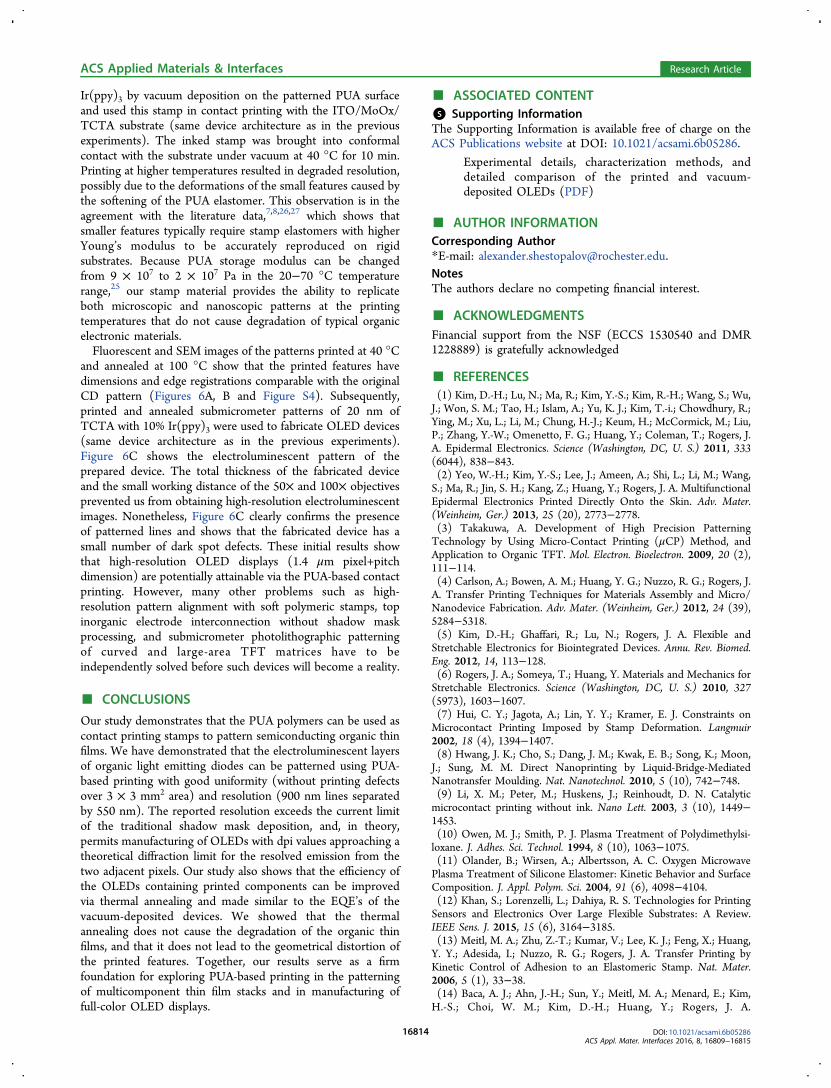
Ir(ppy)3 by vacuum deposition on the patterned PUA surfaceand used this stamp in contact printing with the ITO/MoOx/TCTA substrate (same device architecture as in the previousexperiments). The inked stamp was brought into conformalcontact with the substrate under vacuum at 40 °C for 10 min.Printing at higher temperatures resulted in degraded resolution,possibly due to the deformations of the small features caused bythe softening of the PUA elastomer. This observation is in theagreement with the literature data,7,8,26,27 which shows thatsmaller features typically require stamp elastomers with higherYoung’s modulus to be accurately reproduced on rigidsubstrates. Because PUA storage modulus can be changedfrom 9 × 10⁷ to 2 × 10⁷ Pa in the 20−70 °C temperaturerange,25 our stamp material provides the ability to replicateboth microscopic and nanoscopic patterns at the printingtemperatures that do not cause degradation of typical organicelectronic materials.Fluorescent and SEM images of the patterns printed at 40 °C
and annealed at 100 °C show that the printed features havedimensions and edge registrations comparable with the originalCD pattern (Figures 6A, B and Figure S4). Subsequently,printed and annealed submicrometer patterns of 20 nm ofTCTA with 10% Ir(ppy)3 were used to fabricate OLED devices(same device architecture as in the previous experiments).Figure 6C shows the electroluminescent pattern of theprepared device. The total thickness of the fabricated deviceand the small working distance of the 50× and 100× objectivesprevented us from obtaining high-resolution electroluminescentimages. Nonetheless, Figure 6C clearly confirms the presenceof patterned lines and shows that the fabricated device has asmall number of dark spot defects. These initial results showthat high-resolution OLED displays (1.4 μm pixel+pitchdimension) are potentially attainable via the PUA-based contactprinting. However, many other problems such as high-resolution pattern alignment with soft polymeric stamps, topinorganic electrode interconnection without shadow maskprocessing, and submicrometer photolithographic patterningof curved and large-area TFT matrices have to beindependently solved before such devices will become a reality.
■ CONCLUSIONS
Our study demonstrates that the PUA polymers can be used ascontact printing stamps to pattern semiconducting organic thinfilms. We have demonstrated that the electroluminescent layersof organic light emitting diodes can be patterned using PUA-based printing with good uniformity (without printing defectsover 3 × 3 mm2 area) and resolution (900 nm lines separatedby 550 nm). The reported resolution exceeds the current limitof the traditional shadow mask deposition, and, in theory,permits manufacturing of OLEDs with dpi values approaching atheoretical diffraction limit for the resolved emission from thetwo adjacent pixels. Our study also shows that the efficiency ofthe OLEDs containing printed components can be improvedvia thermal annealing and made similar to the EQE’s of thevacuum-deposited devices. We showed that the thermalannealing does not cause the degradation of the organic thinfilms, and that it does not lead to the geometrical distortion ofthe printed features. Together, our results serve as a firmfoundation for exploring PUA-based printing in the patterningof multicomponent thin film stacks and in manufacturing offull-color OLED displays.
■ ASSOCIATED CONTENT*S Supporting InformationThe Supporting Information is available free of charge on theACS Publications website at DOI: 10.1021/acsami.6b05286.
Experimental details, characterization methods, anddetailed comparison of the printed and vacuum-deposited OLEDs (PDF)
■ AUTHOR INFORMATIONCorresponding Author*E-mail: [email protected] authors declare no competing financial interest.
■ ACKNOWLEDGMENTSFinancial support from the NSF (ECCS 1530540 and DMR1228889) is gratefully acknowledged
■ REFERENCES(1) Kim, D.-H.; Lu, N.; Ma, R.; Kim, Y.-S.; Kim, R.-H.; Wang, S.; Wu,J.; Won, S. M.; Tao, H.; Islam, A.; Yu, K. J.; Kim, T.-i.; Chowdhury, R.;Ying, M.; Xu, L.; Li, M.; Chung, H.-J.; Keum, H.; McCormick, M.; Liu,P.; Zhang, Y.-W.; Omenetto, F. G.; Huang, Y.; Coleman, T.; Rogers, J.A. Epidermal Electronics. Science (Washington, DC, U. S.) 2011, 333(6044), 838−843.(2) Yeo, W.-H.; Kim, Y.-S.; Lee, J.; Ameen, A.; Shi, L.; Li, M.; Wang,S.; Ma, R.; Jin, S. H.; Kang, Z.; Huang, Y.; Rogers, J. A. MultifunctionalEpidermal Electronics Printed Directly Onto the Skin. Adv. Mater.(Weinheim, Ger.) 2013, 25 (20), 2773−2778.(3) Takakuwa, A. Development of High Precision PatterningTechnology by Using Micro-Contact Printing (μCP) Method, andApplication to Organic TFT. Mol. Electron. Bioelectron. 2009, 20 (2),111−114.(4) Carlson, A.; Bowen, A. M.; Huang, Y. G.; Nuzzo, R. G.; Rogers, J.A. Transfer Printing Techniques for Materials Assembly and Micro/Nanodevice Fabrication. Adv. Mater. (Weinheim, Ger.) 2012, 24 (39),5284−5318.(5) Kim, D.-H.; Ghaffari, R.; Lu, N.; Rogers, J. A. Flexible andStretchable Electronics for Biointegrated Devices. Annu. Rev. Biomed.Eng. 2012, 14, 113−128.(6) Rogers, J. A.; Someya, T.; Huang, Y. Materials and Mechanics forStretchable Electronics. Science (Washington, DC, U. S.) 2010, 327(5973), 1603−1607.(7) Hui, C. Y.; Jagota, A.; Lin, Y. Y.; Kramer, E. J. Constraints onMicrocontact Printing Imposed by Stamp Deformation. Langmuir2002, 18 (4), 1394−1407.(8) Hwang, J. K.; Cho, S.; Dang, J. M.; Kwak, E. B.; Song, K.; Moon,J.; Sung, M. M. Direct Nanoprinting by Liquid-Bridge-MediatedNanotransfer Moulding. Nat. Nanotechnol. 2010, 5 (10), 742−748.(9) Li, X. M.; Peter, M.; Huskens, J.; Reinhoudt, D. N. Catalyticmicrocontact printing without ink. Nano Lett. 2003, 3 (10), 1449−1453.(10) Owen, M. J.; Smith, P. J. Plasma Treatment of Polydimethylsi-loxane. J. Adhes. Sci. Technol. 1994, 8 (10), 1063−1075.(11) Olander, B.; Wirsen, A.; Albertsson, A. C. Oxygen MicrowavePlasma Treatment of Silicone Elastomer: Kinetic Behavior and SurfaceComposition. J. Appl. Polym. Sci. 2004, 91 (6), 4098−4104.(12) Khan, S.; Lorenzelli, L.; Dahiya, R. S. Technologies for PrintingSensors and Electronics Over Large Flexible Substrates: A Review.IEEE Sens. J. 2015, 15 (6), 3164−3185.(13) Meitl, M. A.; Zhu, Z.-T.; Kumar, V.; Lee, K. J.; Feng, X.; Huang,Y. Y.; Adesida, I.; Nuzzo, R. G.; Rogers, J. A. Transfer Printing byKinetic Control of Adhesion to an Elastomeric Stamp. Nat. Mater.2006, 5 (1), 33−38.(14) Baca, A. J.; Ahn, J.-H.; Sun, Y.; Meitl, M. A.; Menard, E.; Kim,H.-S.; Choi, W. M.; Kim, D.-H.; Huang, Y.; Rogers, J. A.
ACS Applied Materials & Interfaces Research Article
DOI: 10.1021/acsami.6b05286ACS Appl. Mater. Interfaces 2016, 8, 16809−16815
16814

Semiconductor Wires and Ribbons for High- Performance FlexibleElectronics. Angew. Chem., Int. Ed. 2008, 47 (30), 5524−5542.(15) Sun, Y.; Kim, H.-S.; Menard, E.; Kim, S.; Adesida, I.; Rogers, J.A. Printed Arrays of Aligned GaAs Wires for Flexible Transistors,Diodes, and Circuits on Plastic Substrates. Small 2006, 2 (11), 1330−1334.(16) Sun, Y.; Rogers, J. A. Inorganic Semiconductors for FlexibleElectronics. Adv. Mater. (Weinheim, Ger.) 2007, 19 (15), 1897−1916.(17) Kim, T.-H.; Choi, W. M.; Kim, D.-H.; Meitl, M. A.; Menard, E.;Jiang, H.; Carlisle, J. A.; Rogers, J. A. Printable, Flexible, andStretchable Forms of Ultrananocrystalline Diamond with Applicationsin Thermal Management. Adv. Mater. (Weinheim, Ger.) 2008, 20 (11),2171−2176.(18) Kummamuru, R. K.; Hu, L.; Cook, L.; Efremov, M. Y.; Olson, E.A.; Allen, L. H. A Close Proximity Self-Aligned Shadow Mask forSputter Deposition onto a Membrane or Cavity. J. Micromech.Microeng. 2008, 18 (9), 095027.(19) Ling, M. M.; Bao, Z. Thin Film Deposition, Patterning, andPrinting in Organic Thin Film Transistors. Chem. Mater. 2004, 16(23), 4824−4840.(20) Chen, S.-Z.; Peng, S.-H.; Ting, T.-Y.; Wu, P.-S.; Lin, C.-H.;Chang, C.-Y.; Shyue, J.-J.; Jou, J.-H. Organic Light-Emitting Diodeswith Direct Contact-Printed Red, Green, Blue, and White Light-Emitting Layers. Appl. Phys. Lett. 2012, 101 (15), 153304.(21) Park, T. H.; Park, Y. W.; Choi, J. H.; Choi, H. J.; Jeong, J.-W.;Song, E. H.; Choi, K. C.; Ju, B.-K. Contact Printing of the EmittingLayer for High Performance Multilayered Phosphorescent OrganicLight-Emitting Diodes. Org. Electron. 2011, 12 (6), 1063−1067.(22) Jin, H.; Sturm, J. C. Super-High-Resolution Transfer Printing forFull-Color OLED Display Patterning. J. Soc. Inf. Disp. 2010, 18 (2),141−145.(23) Yu, J.; Bulovic, V. Micropatterning Metal Electrode of OrganicLight Emitting Devices Using Rapid Polydimethylsiloxane Lift-off.Appl. Phys. Lett. 2007, 91 (4), 043102.(24) Lee, T.-W.; Zaumseil, J.; Bao, Z.; Hsu, J. W. P.; Rogers, J. A.Organic Light-Emitting Diodes Formed by Soft Contact Lamination.Proc. Natl. Acad. Sci. U. S. A. 2004, 101 (2), 429−433.(25) Li, J.; Xu, L.; Kim, S.; Shestopalov, A. Urethane-AcrylatePolymers in High-Resolution Contact Printing. J. Mater. Chem. C2016, 4, 4155−4165.(26) Shestopalov, A. A.; Clark, R. L.; Toone, E. J. InklessMicrocontact Printing on Self-Assembled Monolayers of Fmoc-Protected Aminothiols. J. Am. Chem. Soc. 2007, 129 (45), 13818−13819.(27) Shestopalov, A. A.; Clark, R. L.; Toone, E. J. InklessMicrocontact Printing on SAMs of Boc- and TBS-Protected Thiols.Nano Lett. 2010, 10 (1), 43−46.(28) Chopra, K. L.; Major, S.; Pandya, D. K. TransparentConductorsA Status Review. Thin Solid Films 1983, 102 (1), 1−46.(29) Schmidbauer, S.; Hohenleutner, A.; Konig, B. Studies on thePhotodegradation of Red, Green and Blue Phosphorescent OLEDEmitters. Beilstein J. Org. Chem. 2013, 9, 2088−2096.(30) Bowers, C. M.; Zhang, M.; Lyubarskaya, Y.; Toone, E. J.; Tang,C.; Shestopalov, A. A. Structural Modifications in Bilayered MolecularSystems Lead to Predictable Changes in Their Electronic Properties.Adv. Mater. Interfaces 2014, 1 (2), 1300109.(31) Shestopalov, A. A.; Clark, R. L.; Toone, E. J. CatalyticMicrocontact Printing on Chemically Functionalized H-TerminatedSilicon. Langmuir 2010, 26 (3), 1449−1451.(32) Shestopalov, A. A.; Morris, C. J.; Vogen, B. N.; Hoertz, A.;Clark, R. L.; Toone, E. J. Soft-Lithographic Approach to Function-alization and Nanopatterning Oxide-Free Silicon. Langmuir 2011, 27(10), 6478−6485.
ACS Applied Materials & Interfaces Research Article
DOI: 10.1021/acsami.6b05286ACS Appl. Mater. Interfaces 2016, 8, 16809−16815
16815