Embed Size (px)
Citation preview
High-Resolution Iris Image Reconstruction fromLow-Resolution Imagery
R. Barnarda, V. P. Paucaa, T. C. Torgersena, R. J. Plemmonsa,c, S. Prasadg, J. van derGrachtd, J. Nagyb, J. Chungb, G. Behrmanne, S. Mathewsf, M. Mirotznikf
a Department of Computer Science, Wake Forest University, Winston-Salem, NC 27109b Department of Mathematics and Computer Science, Emory University, Atlanta, GA 30322
c Department of Mathematics, Wake Forest University, Winston-Salem, NC 27109d Holospex, Inc., 6470 Freetown Rd., Suite 200-104, Columbia, MD 21044
e EM Photonics Inc., 51 E. Main Street, Suite 203, Newark, DE 19711f Department of Electrical Engineering & Computer Science, Catholic University of America,
Washington, DC 20064g Center for Advanced Studies and Department of Physics and Astronomy, University of New
Mexico, Albuquerque, NM 87131
ABSTRACT
We investigate the use of a novel multi-lens imaging system in the context of biometric identification, and morespecifically, for iris recognition. Multi-lenslet cameras offer a number of significant advantages over standardsingle-lens camera systems, including thin form-factor and wide angle of view. By using appropriate lenslet spac-ing relative to the detector pixel pitch, the resulting ensemble of images implicitly contains subject informationat higher spatial frequencies than those present in a single image. Additionally, a multi-lenslet approach enablesthe use of observational diversity, including phase, polarization, neutral density, and wavelength diversities. Forexample, post-processing multiple observations taken with differing neutral density filters yields an image havingan extended dynamic range. Our research group has developed several multi-lens camera prototypes for theinvestigation of such diversities.
In this paper, we present techniques for computing a high-resolution reconstructed image from an ensemble oflow-resolution images containing sub-pixel level displacements. The quality of a reconstructed image is measuredby computing the Hamming distance between the Daugman4 iris code of a conventional reference iris image,and the iris code of a corresponding reconstructed image. We present numerical results concerning the effect ofnoise and defocus blur in the reconstruction process using simulated data and report preliminary work on thereconstruction of actual iris data obtained with our camera prototypes.
1. INTRODUCTION AND MOTIVATION
Recently, a number of research efforts have investigated the potential of multi-lenslet camera systems, notably,the TOMBO project7 and MONTAGE projects.1 The camera system and techniques described in this paperare guided by a series of workshops hosted at the Oak Ridge National Laboratories (ORNL) held during mid-2005 through 2006 as part of an ARDA seedling challenge project. The workshop series entitled “PracticalEnhanced-Resolution Integrated Optical-Digital Imaging Camera” (PERIODIC) seeks to design and prototypea multi-lenslet camera which can exploit the observational diversity inherent in a multi-lenslet system. A primarymotivation for this project is the need for compact integrated imaging devices capable of resolving the details ofa human iris for biometric identification.
Multi-lenslet camera systems enable the use of many types of observational diversities, including phase,polarization, neutral density, and wavelength diversities. For example, post-processing multiple observationsmade with differing neutral density filters can yield an image having an extended dynamic range. Applicationsinclude surveillance, license plate identification, and other situations where natural lighting may cause excessivecontrast. Phase diversity, and the use of phase encoding masks offer the potential for extended depth of field.
Under appropriate conditions, an ensemble of images formed by a multiple lenslet camera will implicitlycontains subject information at higher spatial frequencies than those present in a single image.12 One notableexception, is the degenerate case in which all lenslet images are shifted by an integer number of pixels from eachother. By choosing an appropriate lenslet spacing, and detector pitch, such degenerate observing conditions canbe avoided for a specific camera application, and the anticipated subject to lens distance.
In this paper, we primarily discuss methods to reconstruct a single high-resolution image from an ensembleof (low-resolution) images. Reconstructions are computed using both simulated observations, and using dataobtained from the PERIODIC prototype camera. Our goal is to explore systems which can process acquireddata into a form suitable for an automated biometric (iris) identification system.
2. PERIODIC IMAGING SYSTEM OVERVIEW
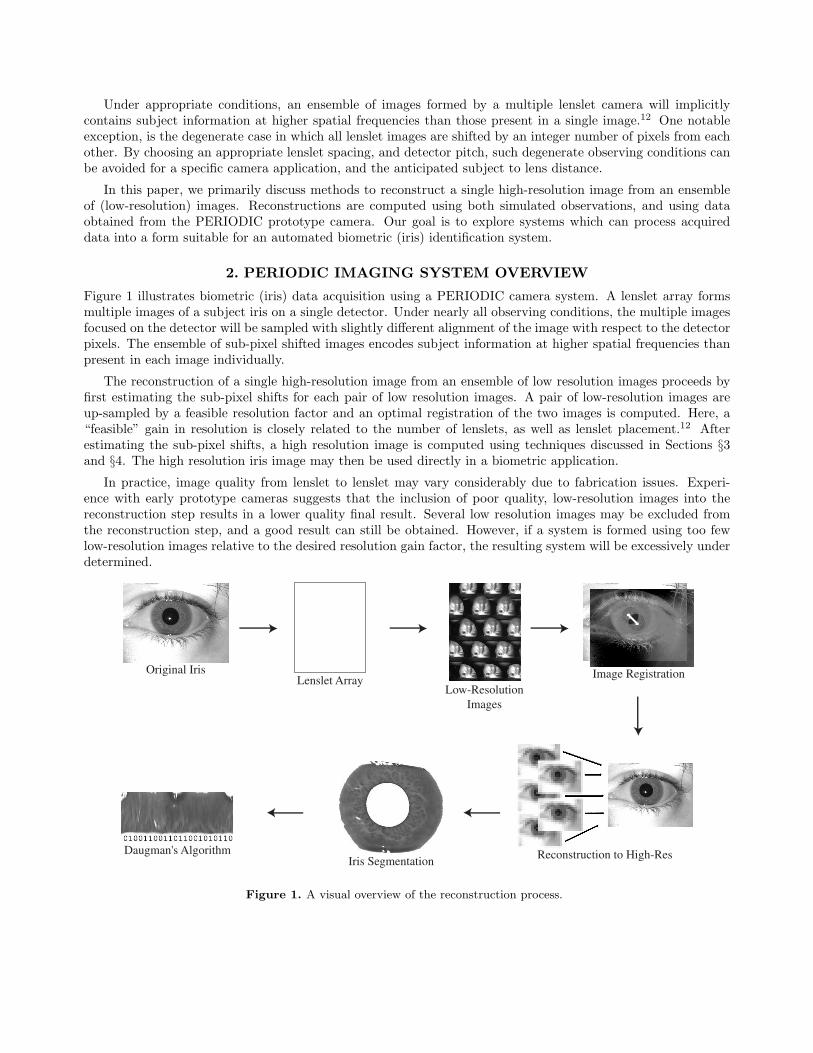
Figure 1 illustrates biometric (iris) data acquisition using a PERIODIC camera system. A lenslet array formsmultiple images of a subject iris on a single detector. Under nearly all observing conditions, the multiple imagesfocused on the detector will be sampled with slightly different alignment of the image with respect to the detectorpixels. The ensemble of sub-pixel shifted images encodes subject information at higher spatial frequencies thanpresent in each image individually.
The reconstruction of a single high-resolution image from an ensemble of low resolution images proceeds byfirst estimating the sub-pixel shifts for each pair of low resolution images. A pair of low-resolution images areup-sampled by a feasible resolution factor and an optimal registration of the two images is computed. Here, a“feasible” gain in resolution is closely related to the number of lenslets, as well as lenslet placement.12 Afterestimating the sub-pixel shifts, a high resolution image is computed using techniques discussed in Sections §3and §4. The high resolution iris image may then be used directly in a biometric application.
In practice, image quality from lenslet to lenslet may vary considerably due to fabrication issues. Experi-ence with early prototype cameras suggests that the inclusion of poor quality, low-resolution images into thereconstruction step results in a lower quality final result. Several low resolution images may be excluded fromthe reconstruction step, and a good result can still be obtained. However, if a system is formed using too fewlow-resolution images relative to the desired resolution gain factor, the resulting system will be excessively underdetermined.
Original Iris Lenslet Array
Low-Resolution
Images
Image Registration
Reconstruction to High-Res Iris Segmentation
Daugman's Algorithm
Figure 1. A visual overview of the reconstruction process.
3. IMAGING SYSTEM MODEL
3.1. The Forward Model
The image formation process is naturally described in the terms of continuous functions. However, for brevity,we begin with the discrete approximation to the continuous model. For a multi-lenslet camera, the low-resolutionimage, gj formed by the jth lenslet is given by:
gj = DHjSjf + ηj , (1)
where,
• f is a target high-resolution representation for the object, stacked as an n2 × 1 vector of pixel values.
• Sj is an n2×n2 matrix representing the translation of image f due to the relative position of lenslet j withrespect to the object and the detector,
• Hj is an n2 × n2 matrix blurring operator associated with lenslet j,
• D is an (n/`)2 ×n2 decimation matrix operator which represents the transformation from the target n×nhigh resolution to the (n/`) × (n/`) (low) resolution of the detector,
• gj is the low-resolution image associated with lenslet j stacked as an (n/`)2 × 1 vector and,
• ηj describes a noise process associated with the jth image.
We refer to ` as the resolution improvement factor.
Equation (1) serves as a framework for both camera simulation and image restoration. For simulationpurposes, we adopt a widely-used noise model6 given by:
ηj =√
gjηj1 + σηj2 (2)
where gj = DHjSjf . Both ηj1 and ηj2 are standard normally distributed random variables with mean equal tozero and variance equal to one. The parameter σ is the standard deviation of the image-independent noise term.The normally distributed term
√gjηj1 in equation (2) approximates the Poisson noise associated with the light
detection process. For purposes of image reconstruction, equation (1) leads to a least squares inverse problemwhose solution is the desired high resolution reconstruction f .
3.2. The Inverse Problem
Recently, a well-developed theory for digital super-resolution has begun to appear in the literature. See, forexample Ref.2,8, 10,12 The implication for the PERIODIC project is that an understanding of the full potential ofmulti-lenslet cameras, as well as their inherent limitations begins to emerge. In practical applications, additionalchallenges arise because of real-world deviations from the models on which the theory is developed. In thissection, we consider the inverse problem associated with equation (1) and some of the challenges associated withpractical application. For an m-lenslet camera we formulate a least-squares cost functional:
J(f) =
∣∣∣∣∣∣∣∣∣
∣∣∣∣∣∣∣∣∣
g1
g2
...gm
−
DH1S1
DH2S2
...DHmSm
f
∣∣∣∣∣∣∣∣∣
∣∣∣∣∣∣∣∣∣2
2
(3)
whose minimum gives the desired estimate f for the high resolution image f , i.e.,
f = argminf { J(f) } . (4)

If the number of lenslets m and the resolution improvement factor ` satisfy m = `2, then the block matrix inequation (3) is square, and the system is fully determined. In practice, we find often that m < `2 and the systemis under-determined. For values of m reasonably close to `2, acceptable reconstructions can still be obtained.Smaller values of m also reduce the computational cost of the reconstruction.
Equations (3) and (4) also present several variations or levels of difficulty, depending on the extent of a prioriknowledge. Several relevant issues are discussed in subsections §3.3 to §3.5 below.
3.3. Estimating the PSF, Hj
In practice, the point spread function Hj is not easily estimated, since the detector only records low-resolutionimages, while Hj operates on the high resolution unknown, f . If Sj is constrained to shifts corresponding to anintegral number of high resolution pixels, then, Hj and Sj commute in equation (1). However, the decimationmatrix D does not commute with Hj , thus, a restoration step using a low-resolution representation of the pointspread function, does not yield information which could be directly helpful for solving the inverse problem inequation (4) for f .
In special cases, Hj may be known. For example, for accurately focused subjects, and sufficiently accuratelyconstructed lenslets, the Hj could be approximated by the diffraction limited PSF, given knowledge of the opticalsystem parameters, such as focal length, F-number, and wavelength. Unfortunately, even simple focus errors aredifficult to know accurately, since focus is affected by small manufacturing errors in the camera and by subjectposition.
Further, low-cost, commodity, lenslets often suffer from large aberrations, including field curvature and othereffects which lead to spatially-varying blurs. While much work9 has been done on the subject of digitally restoringimages containing spatially varying blur, the computational cost of such methods are considered prohibitive forthe practical applications of the PERIODIC camera. Phase encoding masks13 and corresponding (low cost)post-processing are considered to be promising future directions to overcome spatially varying blur, as well asprovide extended depth of field. The PSF of a phase encoding mask can be expected to be known with sufficientaccuracy to ensure a good reconstruction.
3.4. Estimating the Sub-pixel Shift Matrix, Sj
For objects at infinity, sub-pixel shifts are due to lenslet placement relative to the detector pixel pitch. In prac-tice, the sub-pixel shifts may be measured experimentally. Using appropriate equipment and careful technique,reasonably accurate estimates can be expected. For nearby objects, parallax implies that the sub-pixel shifts aredependent on the subject-to-lens distance. Thus, for general purpose applications, the sub-pixel shifts must beestimated from the collection of low-resolution images for each new high-resolution image produced.
Here, two possible scenarios may be pursued. One can consider the joint estimation problem in which bothSj and f in equation (1) are sought simultaneously in a single joint-optimization problem. Several promisingapproaches have been investigated.3
For the PERIODIC camera described in this paper, a sequential two-step approach is chosen. Our approachis motivated by a specific imaging task, i.e., biometric (iris) identification, including the need to process imperfect“real-world” data with a response time acceptable to the end user. Because of the relative rigidity of the detectorand the lenslet array, sub-pixel shifts can be assumed to be uniform across the image, and limited to translations,and possibly, small-angle rotations. In the prototype camera, adjustable stages ensure that the angle of rotationis sufficiently close to zero so that it may be ignored. Thus, only rigid translations remain. In the first phaseof computation, the sub-pixel shift operator Sj is estimated from the low-resolution images by cross-correlationand enumeration. During the second phase, each Sj is held fixed, and the least squares problem describedin equations (3) and (4) is solved using the familiar conjugate gradient method (CGLS) to obtain the desiredhigh-resolution image f .
3.5. Estimating the Decimation Matrix, D
The decimation matrix is perhaps the easiest to estimate of the three matrix factors, since the detector geometryis usually known or is at least measurable. In the simplest case, the sub-sampling process can be approximatedby integrating the high resolution pixels over an appropriate region. More sophisticated approaches mightconsider the effects of inter-pixel gap, and the shape and layout pattern of the active area of the detector pixels.Accurately representing the active area for each low-resolution pixel is especially a concern for some types ofCMOS detectors.
4. IMAGE REGISTRATION AND HIGH RESOLUTION RECONSTRUCTION
As previously mentioned, a sequential two-step approach is chosen to minimize equation (3) with respect to boththe sub-pixel shift operators Sj and the high resolution unknown f . More specifically, given the low resolutionimages gj a registration problem is solved to yield Sj . Then the minimization problem in equation (4) is solvedfor f iteratively using the well-known conjugate gradients method.
4.1. Sub-Pixel Image Registration
Image registration problems arise in a wide variety of applications including astronomy, remote sensing, andmedical imaging. The problem may be described as the process of transforming different sets of data into a singlecoordinate system, to enable the comparison or integration of data obtained from different measurements. Whileextensive literature on the topic has been published over the last several decades, see e.g. Ref.,15 performanceof registration methods remains largely application data dependent. We have explored two registration methodsfor the purpose of rapidly estimating sub-pixel shifts between pairs of PERIODIC images: one based on thenormalized cross-correlation method and the second based on the minimization of an appropriate distance orsimilarity metric.
4.1.1. Approach based on the Normalized Cross-Correlation
The normalized cross-correlation C(x, y) of two real functions h1(x, y) and h2(x, y) is defined as:7
C(x, y) =
∫∫h1(x′, y′)h2(x′ − x, y′ − y)dx′dy′
[∫∫|h1(x, y)|2dxdy
]1/2 [∫∫|h2(x, y)|2dxdy
]1/2(5)
Assuming h1 and h2 have a similar distribution, the relative shift between h1 and h2 is given by (x∗, y∗) =arg maxx,y C(x, y). For sampled images g0 and gj , a discretized correlation sum is used to approximate equation(5), yielding values C(xi, yi) at discrete points (xi, yi). Interpolation may be used to better estimate the locationof the peak.15
An alternative approach consists of calculating the discrete cross-correlation using up-sampled images. Theaccuracy of this approach depends on the up-sampling method as well as on the amount of high frequencyinformation content available in the data. For the iris images, our approach is summarized as follows:
• Up-sample the low-resolution images g0 and gj by a factor r ≥ ` using either bilinear or bicubic interpola-tion,
• Filter the up-sampled images using high-pass filtering and thresholding to isolate the specular reflection inthe pupil, and
• Calculate the discrete cross-correlation between the up-sampled resulting filtered images and find thedisplacements corresponding to the maximum correlation.
4.1.2. Approach based on Minimization of a Distance Metric
Minimizing the distance between two different images of the same object in some metric space is a naturalapproach for image registration. Several distance metrics may be applied, including Euclidean distance, mutualinformation, and normal gradient fields.
Using a Euclidean distance metric, our image registration problem can be formulated as follows. Let g0
denote a reference image, and let gj denote a target image of interest, both represented by stacked (n/`)2 × 1vectors. Let T (∆x,∆y) denote a (n/`)2 × (n/`)2 image shift matrix operator whose entries are a continuousfunction of the shift offsets ∆x and ∆y. Naturally, non-integer shifts involve some form of interpolation, anda number of widely-used methods (e.g., nearest neighbor, bilinear, etc.) are available to form T (∆x, ∆y). Adetailed description of methods for constructing the shift operator from sub-pixel displacements can be found inRef.3
Then, the registration problem may be described by:
(∆x, ∆y) = argmin∆x,∆y
{||g0 − T (∆x, ∆y)gj ||22
}(6)
Unfortunately, equation (6) is extremely difficult to solve in general, since a textured subject can lead tonumerous local minima. A more tractable formulation of the registration problem given by equations (7) and(8) below. The basic idea is to seek an optimal registration over a discrete set of integer displacements using twoup-sampled images.
Let Sj(∆p, ∆q) denote an (rn/`)2×(rn/`)2 matrix representing a shift by integer numbers ∆p and ∆q of high-resolution pixels. Each shift of one high-resolution pixel corresponds to a sub-pixel shift by 1/r low-resolutionpixels. Let U denote an (rn/`)2 × (n/`)2 up-sample matrix operator. We define an objective functional K,
K(∆p, ∆q) = ||Ug0 − Sj(∆p, ∆q)Ugj ||22 . (7)
Then, the registration problem can be formulated as:
(∆p, ∆q) = argmin∆p,∆q { K(∆p, ∆q) } (8)
Equation (8) is solved by starting with the correlation approach described in Section §4.1.1. The shiftsindicated by the peak correlation are then refined by enumeration of all shifts contained in a small neighborhoodof the peak and evaluation of the distance metric (7). This approach is computationally viable because inpractice, only a small neighborhood is required.
For high accuracy, it is natural to choose a relatively large value of the up-sample factor r. However, as theup-sample factor increases, the corresponding processing time implied by equation (8) grows geometrically. Amore efficient algorithm can be constructed by starting with a small up-sample factor, e.g., r = 2 which yields aninitial estimate of the sub-pixel shifts. The initial estimate can then be recursively improved by up-sampling anappropriate neighborhood containing the current approximate solution, and re-computing the minimal distancemetric in the up-sampled region.
4.2. Reconstruction
Once the sub-pixel displacements are computed for all images gj , j = 1, 2, ...,m, the shift operators Sj in equation(3) are well defined. Reconstruction proceeds by minimizing J(f) by the well known method of conjugate gradi-ents (CGLS). While a number of accelerated-convergence methods, such as pre-conditioned conjugate gradientsare well known, we adopt CGLS for comparative purposes as illustrated in Section §5. Section §5 describes aseries of numerical experiments, and uses a biometric measure, i.e., the Hamming distance between Daugman4
iris codes to evaluate image quality.
5. NUMERICAL RESULTS
In this section, we explore the efficacy of the sequential two-step approach described in Section §4 for thereconstruction of iris imagery. First, we apply our approach to simulated iris data to characterize the effectof noise and misfocus blur on the achievable reconstruction quality. We use both the relative error of thereconstructed image and the Hamming distance4 between the reconstructed iris code and a reference iris codeas image quality metrics. Second, our approach is applied to real iris imagery obtained from a multi-lensletPERIODIC prototype camera. Hamming distance (HD) is used to quantify the quality of the reconstructediris data. Finally, we define a Hamming distance improvement factor b(σ) to facilitate a comparison betweenhigh-resolution reconstructions and low-resolution images, at the same noise level σ,
b(σ) =HD of reference low-res image
HD of reconstructed high-res image. (9)
5.1. Characterization of Noise and Misfocus Effects on Image Reconstruction
We have conducted a large number of experiments to characterize the effect of various factors in the imagereconstruction process, including noise, misfocus, registration and deblurring. We present results concerning theeffect of noise and blur in the reconstruction process and comment on the effect of mis-registration and inaccuratedeblurring.
The simulated iris data was constructed using the image formation model described in Section 3. The targethigh-resolution image used to form f is of size 296×296. Ten low-resolution images of size 74×74 were constructedusing equation (1) to form vectors gj , (j = 1, 2, ..., 10). Thus, the resolution improvement factor is ` = 4. These10 low-resolution images contain different 1/4-pixel shifts, as characterized by the shifting operators Sj . Theblurring operators Hj are given by either the identity matrix I (for the case of no blurring) or by Gaussianblurs with standard deviation equal to 1, 5, and 10. The noise is modeled using equation (2) including bothsignal-dependent and signal-independent terms6 for values of σ = c · max(gj) for each c ∈ {0.001, 0.01, 0.05}.
For the reconstruction of simulated data, we consider the ideal case of known shifting operators Sj andcompute the solution of the inverse problem given by equation (4). Notice that the reconstruction matrix[DHjSj ] is underdetermined (5/8 ∗ 2962 × 2962), and thus generally consistent with practical scenarios.
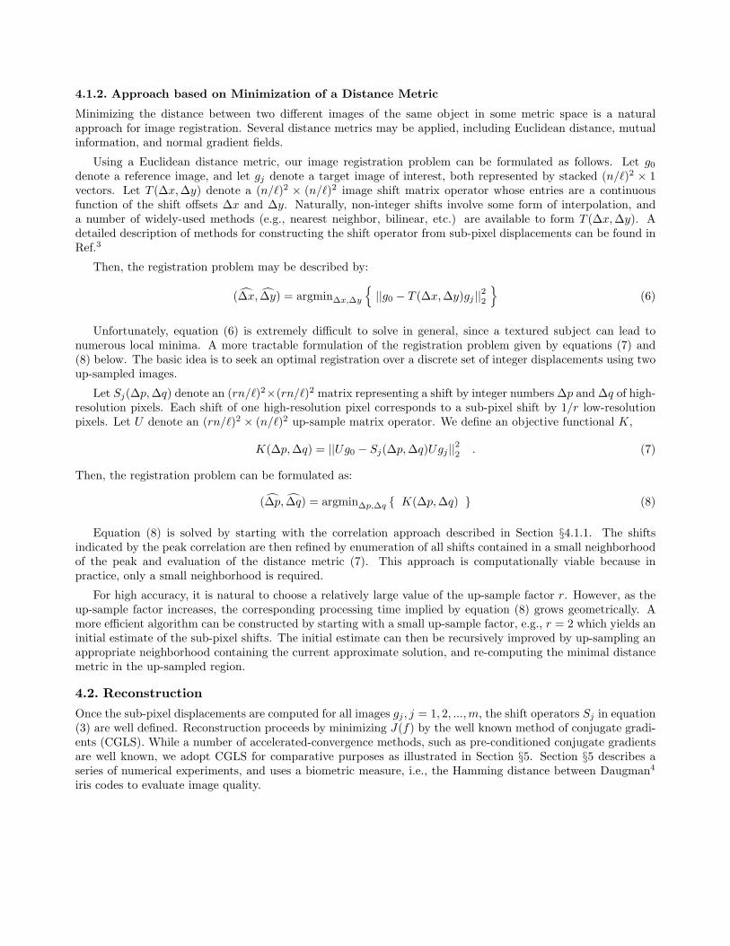
Reconstruction of Simulated Data Containing no Defocus Blur (Hj = I). We first consider thecase where the object is placed at the optimal object-to-camera distance and hence contains no defocus blur.Figure 2a-c shows the effect of increasing noise on the relative error and Hamming distance at each iteration. Thecurves labeled as ”baseline” indicate performance in the absence of noise. The dotted line at 0.32 is the matchingcut-off for HD.∗ The dash-dot line is the HD of a reference low-resolution image. Later plots are illustrated in asimilar manner.
The relative error curves show the semi-convergent behavior typical of iterative algorithms, such as CGLS,due to the reconstruction of the noise subspace. Notice that while the baseline relative error continues to (slowly)decay, the relative error in the presence of noise quickly reaches a minimum and starts to increase. The HD ofthe reconstructions is however equal to 0 at the first few iterations for all three cases and eventually goes up asnoise increases. Thus, in terms of achievable HD, the high-resolution images produce HD=0 for all noise values,whereas the HD of the reference low-resolution image is 0.17 for noise=0.05.
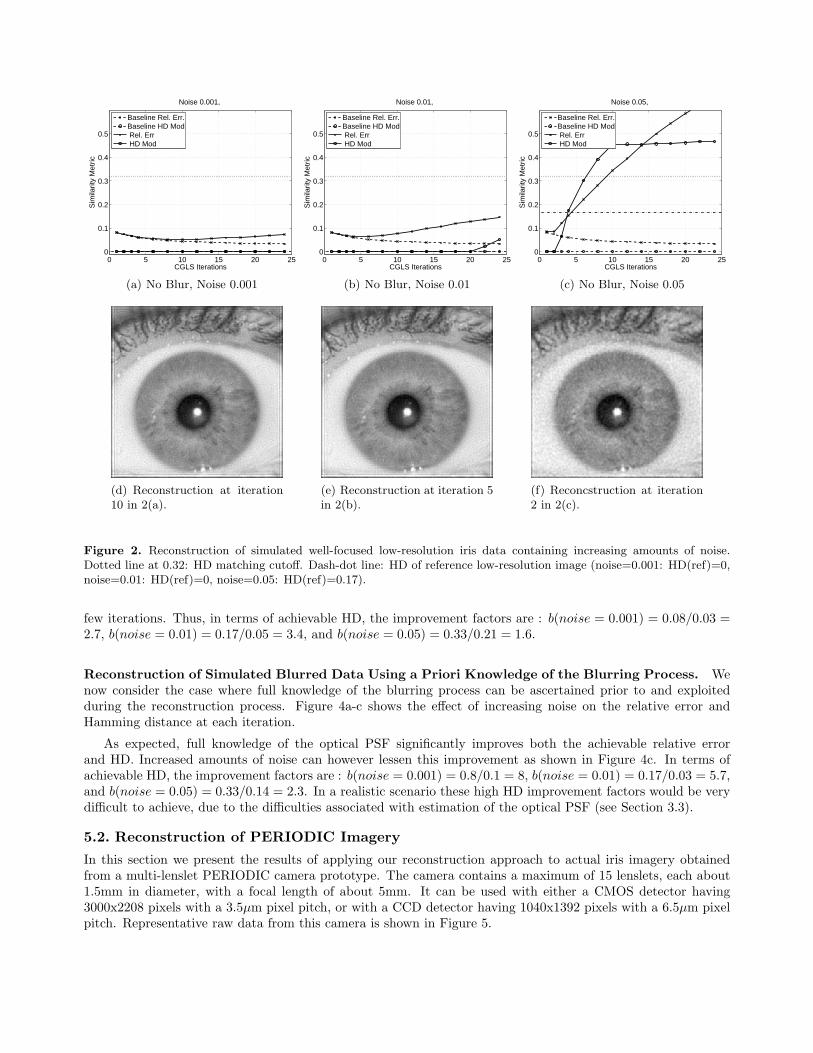
Reconstruction of Simulated Blurred Data without a Priori Knowledge of the Blurring Process.We now consider the case where the object is misplaced with respect to the camera, producing an image witha proportional amount of blur. We assume no knowledge of the blur in the reconstruction process, i.e. Hj = I.Figure 3a-c shows the effect of increasing noise on the relative error and Hamming distance at each iteration.
Clearly, without knowledge of the blurring process, the relative error quickly increases after the first iteration.However the HD is significantly improved with respect to that of the reference low-resolution image over the first
∗All tests performed compared images of the same eye, thus true positive matches are expected.
0 5 10 15 20 250
0.1
0.2
0.3
0.4
0.5
CGLS Iterations
Sim
ilarit
y M
etric
Noise 0.001,
Baseline Rel. Err.Baseline HD Mod Rel. Err HD Mod
(a) No Blur, Noise 0.001
0 5 10 15 20 250
0.1
0.2
0.3
0.4
0.5
CGLS Iterations
Sim
ilarit
y M
etric
Noise 0.01,
Baseline Rel. Err.Baseline HD Mod Rel. Err HD Mod
(b) No Blur, Noise 0.01
0 5 10 15 20 250
0.1
0.2
0.3
0.4
0.5
CGLS Iterations
Sim
ilarit
y M
etric
Noise 0.05,
Baseline Rel. Err.Baseline HD Mod Rel. Err HD Mod
(c) No Blur, Noise 0.05
(d) Reconstruction at iteration10 in 2(a).
(e) Reconstruction at iteration 5in 2(b).
(f) Reconcstruction at iteration2 in 2(c).
Figure 2. Reconstruction of simulated well-focused low-resolution iris data containing increasing amounts of noise.Dotted line at 0.32: HD matching cutoff. Dash-dot line: HD of reference low-resolution image (noise=0.001: HD(ref)=0,noise=0.01: HD(ref)=0, noise=0.05: HD(ref)=0.17).
few iterations. Thus, in terms of achievable HD, the improvement factors are : b(noise = 0.001) = 0.08/0.03 =2.7, b(noise = 0.01) = 0.17/0.05 = 3.4, and b(noise = 0.05) = 0.33/0.21 = 1.6.
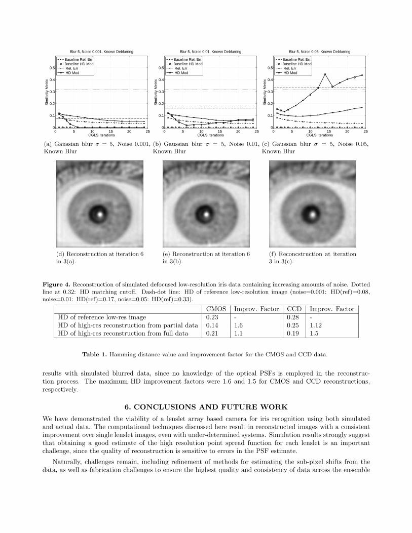
Reconstruction of Simulated Blurred Data Using a Priori Knowledge of the Blurring Process. Wenow consider the case where full knowledge of the blurring process can be ascertained prior to and exploitedduring the reconstruction process. Figure 4a-c shows the effect of increasing noise on the relative error andHamming distance at each iteration.
As expected, full knowledge of the optical PSF significantly improves both the achievable relative errorand HD. Increased amounts of noise can however lessen this improvement as shown in Figure 4c. In terms ofachievable HD, the improvement factors are : b(noise = 0.001) = 0.8/0.1 = 8, b(noise = 0.01) = 0.17/0.03 = 5.7,and b(noise = 0.05) = 0.33/0.14 = 2.3. In a realistic scenario these high HD improvement factors would be verydifficult to achieve, due to the difficulties associated with estimation of the optical PSF (see Section 3.3).
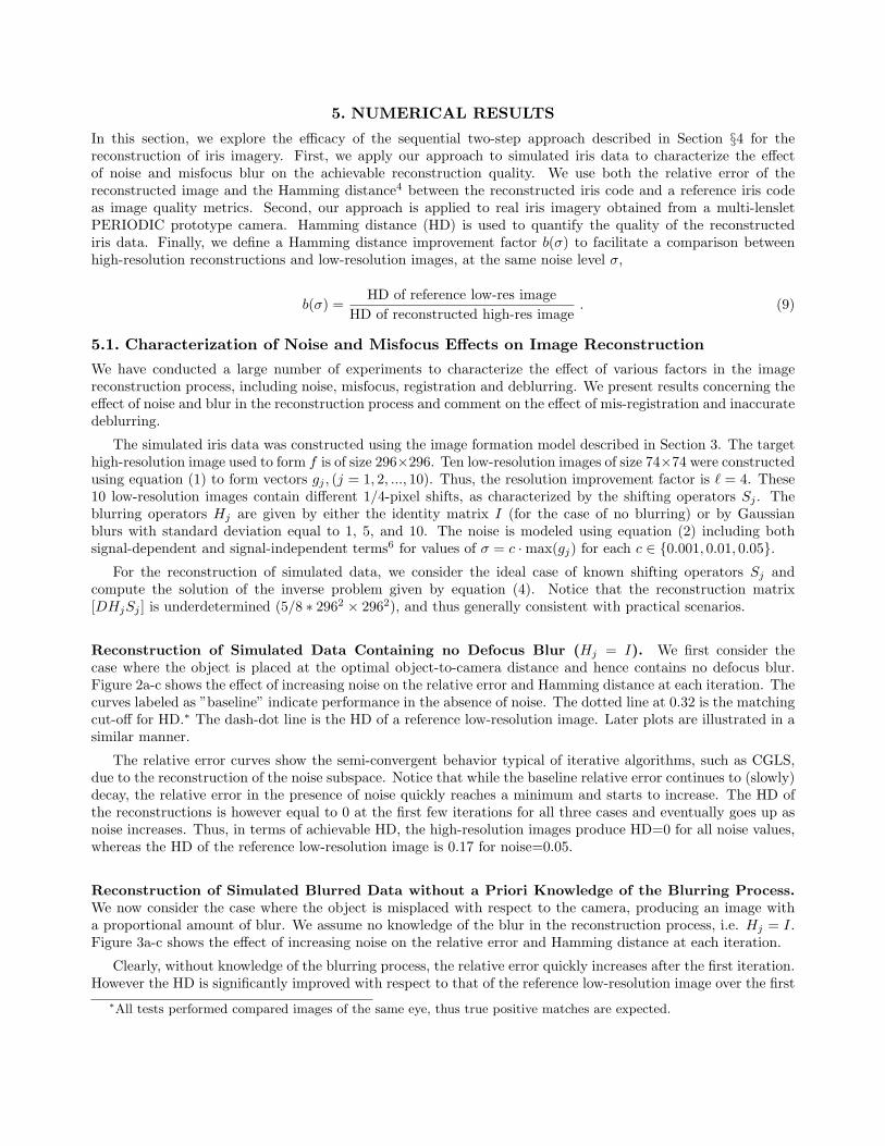
5.2. Reconstruction of PERIODIC Imagery
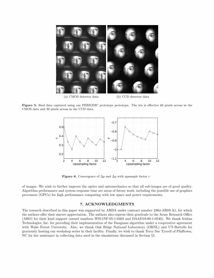
In this section we present the results of applying our reconstruction approach to actual iris imagery obtainedfrom a multi-lenslet PERIODIC camera prototype. The camera contains a maximum of 15 lenslets, each about1.5mm in diameter, with a focal length of about 5mm. It can be used with either a CMOS detector having3000x2208 pixels with a 3.5µm pixel pitch, or with a CCD detector having 1040x1392 pixels with a 6.5µm pixelpitch. Representative raw data from this camera is shown in Figure 5.
0 5 10 15 20 250
0.1
0.2
0.3
0.4
0.5
CGLS Iterations
Sim
ilarit
y M
etric
Blur 5, Noise 0.001, No Deblur
Baseline Rel. Err.Baseline HD Mod Rel. Err HD Mod
(a) Gaussian blur σ = 5, Noise 0.001
0 5 10 15 20 250
0.1
0.2
0.3
0.4
0.5
CGLS Iterations
Sim
ilarit
y M
etric
Blur 5, Noise 0.01, No Deblur
Baseline Rel. Err.Baseline HD Mod Rel. Err HD Mod
(b) Gaussian blur σ = 5, Noise 0.01
0 5 10 15 20 250
0.1
0.2
0.3
0.4
0.5
CGLS Iterations
Sim
ilarit
y M
etric
Blur 5, Noise 0.05, No Deblur
Baseline Rel. Err.Baseline HD Mod Rel. Err HD Mod
(c) Gaussian blur σ = 5, Noise 0.05
(d) Reconstruction at iteration 1in 3(a).
(e) Reconstruction at iteration 1in 3(b).
(f) Reconcstruction at iteration1 in 3(c).
Figure 3. Reconstruction of simulated defocused low-resolution iris data containing increasing amounts of noise. Dottedline at 0.32: HD matching cutoff. Dash-dot line: HD of reference low-resolution image (noise=0.001: HD(ref)=0.08,noise=0.01: HD(ref)=0.17, noise=0.05: HD(ref)=0.33).
Data obtained with the CMOS detector contains a significant amount of signal-dependent as well as fixed-pattern noise. The latter noise is clearly visible in Figures 7a-b, where it shows as bright specs distributedin a pattern across the image. Raw data obtained with either the CMOS or CCD detectors is appropriatelysegmented based on the lenslet geometry before reconstruction.
We apply both normalized cross-correlation (NCC) and the distance metric based optimization methodsdescribed in Section 4 for registration. Results obtained with NCC were poor; this may have been due in partto dominance of signal-dependent noise in the raw data.5 Reconstruction of the iris data using these poorregistration values gave essentially no gain in the HD improvement factor. In contrast registration based on theminimization approach of equation (8) produced parameters (lateral offsets ∆p and ∆q) of much higher accuracy.Figure 6 shows convergence of these parameters with upsample factor r for a pair of CCD low-resolution images.
A summary of the achievable HD values obtained in the reconstruction of both CMOS and CCD iris data isshown in the Table 1. Reconstruction with partial data refers to the use of 5 out of 15 CMOS and 10 CCD low-resolution images in the reconstruction process. The corresponding low-resolution images and high-resolutionreconstructions are shown in Figure 7. Notice that for the CMOS detector, the HD for reconstruction with fulldata (0.21) is higher than the HD for reconstruction with partial data (0.14). This shows that inclusion of lowquality frames can negatively impact the reconstruction.
Figure 8 shows the Hamming distance at each iteration of CGLS. The HD value decreased in the first two iter-ations of CGLS and then increased with subsequent iterations. This is expected, in light of our experimentation
0 5 10 15 20 250
0.1
0.2
0.3
0.4
0.5
CGLS Iterations
Sim
ilarit
y M
etric
Blur 5, Noise 0.001, Known Deblurring
Baseline Rel. Err.Baseline HD Mod Rel. Err HD Mod
(a) Gaussian blur σ = 5, Noise 0.001,Known Blur
0 5 10 15 20 250
0.1
0.2
0.3
0.4
0.5
CGLS Iterations
Sim
ilarit
y M
etric
Blur 5, Noise 0.01, Known Deblurring
Baseline Rel. Err.Baseline HD Mod Rel. Err HD Mod
(b) Gaussian blur σ = 5, Noise 0.01,Known Blur
0 5 10 15 20 250
0.1
0.2
0.3
0.4
0.5
CGLS Iterations
Sim
ilarit
y M
etric
Blur 5, Noise 0.05, Known Deblurring
Baseline Rel. Err.Baseline HD Mod Rel. Err HD Mod
(c) Gaussian blur σ = 5, Noise 0.05,Known Blur
(d) Reconstruction at iteration 6in 3(a).
(e) Reconstruction at iteration 6in 3(b).
(f) Reconcstruction at iteration3 in 3(c).
Figure 4. Reconstruction of simulated defocused low-resolution iris data containing increasing amounts of noise. Dottedline at 0.32: HD matching cutoff. Dash-dot line: HD of reference low-resolution image (noise=0.001: HD(ref)=0.08,noise=0.01: HD(ref)=0.17, noise=0.05: HD(ref)=0.33).
CMOS Improv. Factor CCD Improv. FactorHD of reference low-res image 0.23 - 0.28 -HD of high-res reconstruction from partial data 0.14 1.6 0.25 1.12HD of high-res reconstruction from full data 0.21 1.1 0.19 1.5
Table 1. Hamming distance value and improvement factor for the CMOS and CCD data.
results with simulated blurred data, since no knowledge of the optical PSFs is employed in the reconstruc-tion process. The maximum HD improvement factors were 1.6 and 1.5 for CMOS and CCD reconstructions,respectively.
6. CONCLUSIONS AND FUTURE WORK
We have demonstrated the viability of a lenslet array based camera for iris recognition using both simulatedand actual data. The computational techniques discussed here result in reconstructed images with a consistentimprovement over single lenslet images, even with under-determined systems. Simulation results strongly suggestthat obtaining a good estimate of the high resolution point spread function for each lenslet is an importantchallenge, since the quality of reconstruction is sensitive to errors in the PSF estimate.
Naturally, challenges remain, including refinement of methods for estimating the sub-pixel shifts from thedata, as well as fabrication challenges to ensure the highest quality and consistency of data across the ensemble
(a) CMOS detector data (b) CCD detector data
Figure 5. Real data captured using our PERIODIC prototype prototype. The iris is effective 60 pixels across in theCMOS data and 30 pixels across in the CCD data.
2 4 6 8 10 12
0.2
0.3
0.4
0.5
Upsampling factor
x
2 4 6 8 10 12−1.1
−1
−0.9
−0.8
−0.7
Upsampling factor
y
Figure 6. Convergence of ∆p and ∆q with upsample factor r.
of images. We wish to further improve the optics and optomechanics so that all sub-images are of good quality.Algorithm performance and system response time are areas of future work, including the possible use of graphicsprocessors (GPUs) for high performance computing with low space and power requirements.
7. ACKNOWLEDGMENTS
The research described in this paper was supported by ARDA under contract number 2364-AR03-A1, for whichthe authors offer their sincere appreciation. The authors also express their gratitude to the Army Research Office(ARO) for their kind support (award numbers W911NF-05-1-0402 and DAAD19-00-1-0540). We thank IridianTechnologies, Inc. for providing their implementation of the Daugman algorithm under a cooperative agreementwith Wake Forest University. Also, we thank Oak Ridge National Laboratory (ORNL) and UT-Battelle forgraciously hosting our workshop series in their facility. Finally, we wish to thank Terry Sue Tyrrell of Pfafftown,NC for her assistance in collecting data used in the simulations discussed in Section §5.
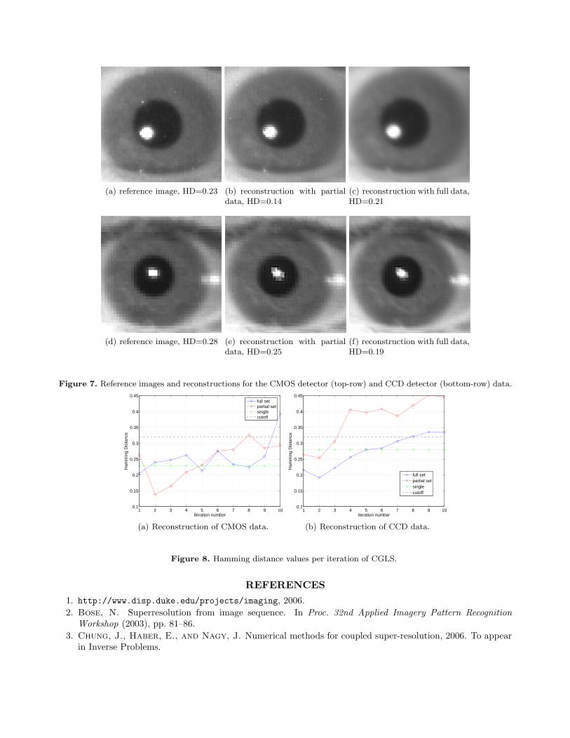
(a) reference image, HD=0.23 (b) reconstruction with partialdata, HD=0.14
(c) reconstruction with full data,HD=0.21
(d) reference image, HD=0.28 (e) reconstruction with partialdata, HD=0.25
(f) reconstruction with full data,HD=0.19
Figure 7. Reference images and reconstructions for the CMOS detector (top-row) and CCD detector (bottom-row) data.
1 2 3 4 5 6 7 8 9 100.1
0.15
0.2
0.25
0.3
0.35
0.4
0.45
iteration number
Ham
min
g D
ista
nce
full setpartial setsinglecutoff
(a) Reconstruction of CMOS data.
1 2 3 4 5 6 7 8 9 100.1
0.15
0.2
0.25
0.3
0.35
0.4
0.45
iteration number
Ham
min
g D
ista
nce
full setpartial setsinglecutoff
(b) Reconstruction of CCD data.
Figure 8. Hamming distance values per iteration of CGLS.
REFERENCES1. http://www.disp.duke.edu/projects/imaging, 2006.2. Bose, N. Superresolution from image sequence. In Proc. 32nd Applied Imagery Pattern Recognition
Workshop (2003), pp. 81–86.3. Chung, J., Haber, E., and Nagy, J. Numerical methods for coupled super-resolution, 2006. To appear
in Inverse Problems.
4. Daugman, J. The importance of being random: statistical principles of iris recognition. Pattern Recognition36 (2003), 279–291.
5. Gratadour, D., Mugnier, L., and Rouan, D. Sub-pixel image registration with a maximum likelihoodestimator. application to the first adaptive optics observations of arp 220 in the l’ band. Astronomy andAstrophysics 443, 1 (2005), 357–365.
6. Jain, A. K. Fundamentals of digital image proccessing. Information and System Sciences. Prentice-HallInternational, 1989.
7. Kitamura, Y., Shogenji, R., Yamada, K., Miyatake, S., Miyamoto, M., Morimoto, T., Masaki,Y., Kondou, N., Miyazaki, D., Tanida, J., and Ichioka, Y. Reconstruction of a high-resolution imageon a compound-eye image-capturing system. Applied Optics 43, 8 (2004), 1719–1727.
8. Lin, Z., and Shum, H.-Y. Fundamental limits of reconstruction-based superresolution algorithms underlocal translation. IEEE Trans. on Pattern Analysis and Machine Intelligence 26, 1 (2004), 83–97.
9. Nagy, J., and O’Leary, D. Restoring images degraded by spatially-variant blur. SIAM J. Sci. Comput.19 (1998), 1063–1082.
10. Park, S., Park, M., and Kang, M. Super-resolution image reconstruction: A technical overview. IEEESignal Processing Magazine 20, 3 (2003), 21–36.
11. Plemmons, R., Horvath, M., Leonhardt, E., Pauca, V., Prasad, S., Robinson, S., Setty,H., Torgersen, T., van der Gracht, J., Dowski, E., Narayanswamy, R., and Silveira, P.Computational imaging systems for iris recognition. In Proc. SPIE, Advanced Signal Processing Algorithms,Architectures, and Implementations XIV (Denver, CO, Aug. 2004), vol. 5559, SPIE, SPIE, pp. 346–357.
12. Prasad, S. Digital superresolution and the generalized sampling theorem, 2006. Submitted to the OpticalSociety of America.
13. Prasad, S., Pauca, V., Plemmons, R., Torgersen, T., and van der Gracht, J. Pupil-phaseoptimization for extended-focus aberration-corrected imaging systems. In Proc. SPIE, Advanced SignalProcessing Algorithms, Architectures, and Implementations XIV (Denver, CO, Aug. 2004), vol. 5559, SPIE,SPIE, pp. 335–345.
14. Roche, A., Malandain, G., and Ayache, N. Unifying maximum likelihood approaches in medical imageregistration. Patern Recognition 11, 1 (2000), 71–80.
15. Zitova, B., and Flusser, J. Image registration methods: a survey. Image and Vision Computing 21(2003), 977–1000.


![1992-8645 IMAGE FUSION TECHNIQUES FOR IRIS AND · PDF fileand iris boundary. In iris segmentation the iris ... lower eyelid using the linear Hough transform [13]. In this paper Iris](https://img.pdfslide.us/doc/110x75/5aac91c37f8b9aa06a8d31f9/1992-8645-image-fusion-techniques-for-iris-and-iris-boundary-in-iris-segmentation.jpg)