Embed Size (px)
Citation preview

STANDARD SYSTEM WITH ONE-PIECE BASEOWNER’S MANUAL
HIGH RATE SAND FILTER
WARNING: A GFCI is required. Follow national and local building and safety codes.
Your ClearWater Standard Sand Filter System is shipped complete from Waterway, with all needed components ready for assembly and installation.
System will require a 110 Volt / 20 Amp service. DO NOT use extension cords. Use will void warranty on pump motor. The pool equipment should be located between the pool skimmer and return line. The filtration system should not be installed less than 2 ft. and no more than 5ft. from the pool. The ClearWater Standard Sand Filter System needs to be on a completely flat level
/ surface (patio block, cement slab, etc.). Assemble filter system only after above ground pool is installed. Fill pool with water. IMPORTANT: Do no raise water level above pool return line or skimmer throat until installation is complete.
Open shipping carton in an upright position, checking contents, as follows:
WARNING! READ ALL INSTRUCTIONS AND WARNING LABELS BEFORE OPERATING FILTER!
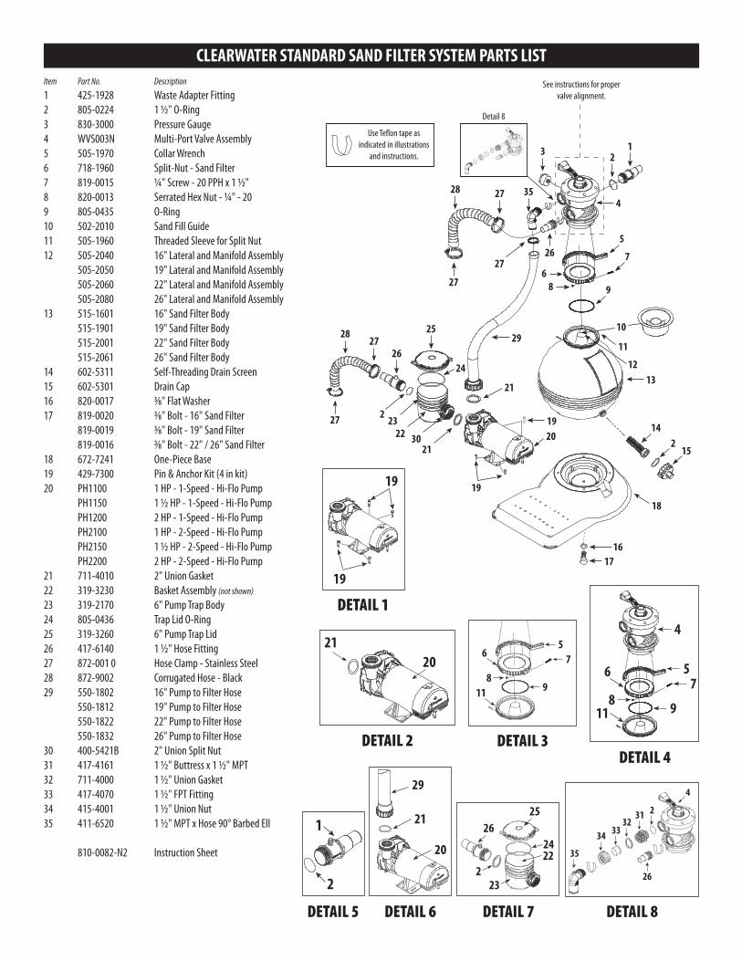
1. Place filter with filter base on a level, secure surface. There is no need to disassemble filter or pump assemblies. Position sand filter body securely onto filter base. Align drain with drain clearance on base. Secure sand filter body to base using bolt (#17) and washer (#16) as shown. DO NOT over tighten.2. Open box and remove pump and trap. Open pump trap lid (#25) and remove 2" gasket. Position gasket into end of pump trap union nut. Hand tighten union nut onto suction side of pump (Detail 2). DO NOT over tighten.3. Secure pump to pump base using pin and anchor kit (#19) (Detail 1).4. Remove collar assembly from filter tank. DO NOT lose screws. IMPORTANT: To prevent damage to internal filter lateral components, fill filter tank full with water prior to adding sand. With sand fill guide (#10) positioned in filter tank opening, add only recommended #20 grade silica sand (see Fill Chart). Remove sand fill guide. IMPORTANT: Clean and remove all debris from filter tank flange after adding sand.5. Assure that o-ring (#9) is positioned onto multi-port throat. 6. Install multi-port valve with inlet and outlet ports facing pool. Top of internal stand pipe seats directly into multi-port valve. Push multi-port valve evenly onto tank flange. NOTE: Make sure tank flange is clear of any sand debris.7. Install filter tank split-nut assembly (#6 & 7) by threading collar clockwise until hand tight. Then use collar wrench (#5) to tighten further (Detail 3).
8. To use collar wrench (#5), place on collar assembly, use both hands to turn wrench 1/2 to 3/4 of a turn to secure multi-port valve to filter body (Detail 4).9. Position and hand tighten pump hose assembly (#29) to top inlet port. Position gasket (#21) and hand tighten onto pump (Detail 6). DO NOT over tighten.10. Apply Teflon tape (4 wraps ideal) and hand tighten 1 1/2" hose fitting (#26) to bottom outlet port. DO NOT over tighten.11. Place 1 1/2" o-ring (#2) over 1 1/2" buttress x 1 1/2" MPT fitting (#31). Thread into pump port of multi-port valve. Slip 1 1/2" union nut (#34) over 1 1/2" female thread fitting (#33). Apply Teflon tape to threads on hose barb 90° ell (#35) and thread into female thread fitting (#33). Keeping 1 1/2" Union Gasket (#32) between fittings (#31 & 33), thread 1 1/2" union nut (#34) onto fitting (#31) on multi-port. Before tightening union nut, turn 90° ell (#35) in proper direction to receive hose (#29) tighten nut (#34) (Detail 8). 12. Position o-ring (#2) onto 1 1/2" hose fitting (#26). Hand-tighten onto suction side of pump trap (Detail 7).13. Apply Teflon tape (4 wraps ideal) to pressure gauge (#3). Thread into multi-port valve.14. Remove 4 hose clamps (#27) and position over end of corrugated hoses (#28). Install corrugated hose between the 1 1/2" hose fitting (#26) on multi-port valve and to pool return fitting. Tighten hose clamps. Install the other corrugated hose between the 1 1/2" hose fitting (#26) on pump trap and to pool skimmer fitting. Tighten hose clamps. NOTE: Soften hose ends with warm water to ease installation onto fittings (if necessary).15. Install waste adapter fitting (#1) with o-ring (#2) (Detail 5).
CLEARWATER STANDARD SAND FILTER SYSTEM OWNER’S MANUAL
INSTALLATION INSTRUCTIONS
1. One-piece mounting base2. One pump3. One filter4. Two corrugated hoses
5. One fittings bag6. One collar wrench7. Trap assemblies8. Pump to filter hose
NOTE: When pressure gauge reading is 5 PSI or higher than original starting pressure, the filter needs to be cleaned. The ClearWater Standard Sand Filter System features our exclusive 7-Position Multi-Port Valve, which ensures safe and simple filter maintenance.
Pressurized vessel. Never attempt to loosen or open collar assembly (#6 & 7) while system is running. It could cause severe injury or harm to user. NEVER CHANGE VALVE POSITION WITH PUMP RUNNING!
1. Turn off pump. 2. Attach backwash hose (optional) to waste port adapter. 3. Rotate multi-port valve handle to Backwash position. Turn pump on and run for 90 second intervals or until discharge water is clear. Turn pump off.4. Rotate multi-port valve handle to Rinse position. Turn pump on for 30 seconds. 5. Repeat steps 3 & 4 until all discharge water is clear while pump is turned on.6. Rotate multi-port valve handle to Filter position. Turn pump on. Valve is now in normal operating position.
1. Fill pool until water is halfway up length of skimmer throat. 2. Make sure pump trap is full of water. Slightly loosen trap lid to relieve pressure and allow water to fill trap. Re-tighten lid.3. Make sure multi-port valve handle is in Filter position. 4. Plug pump into GFCI outlet and turn pump on. Turn two-speed pumps to high.5. Make note of start-up pressure on gauge.6. Checks for leaks.
1. Backwash filter system completely. See Cleaning Instructions.2. Run a filter cleaning chemical through filter system as per cleaner instructions.3. Turn pump off. Disconnect hoses from skimmer and return fitting.4. Remove drain plug cap from bottom of filter tank. DO NOT remove hex drain assembly (#14). To remove Item self-threading drain screen (#14), remove drain cap (#15) and use as tool to remove.5. Unscrew drain plugs located at bottom of pump trap and front of pump housing. Let water drain completely.6. Disconnect filter to pump connection. Loosen union connection on discharge of pump and remove from pump. DO NOT lose 2" union gasket. Lift and remove pump and pump base from filter base. Store inside.
CLEANING INSTRUCTIONSSYSTEM START UP
WINTERIZATION
CLEARWATER STANDARD SAND FILTER SYSTEM PARTS LISTItem Part No. Description
1 425-1928 Waste Adapter Fitting2 805-0224 1 1/2" O-Ring3 830-3000 Pressure Gauge4 WVS003N Multi-Port Valve Assembly5 505-1970 Collar Wrench6 718-1960 Split-Nut - Sand Filter7 819-0015 1/4" Screw - 20 PPH x 1 1/2"8 820-0013 Serrated Hex Nut - 1/4" - 209 805-0435 O-Ring10 502-2010 Sand Fill Guide11 505-1960 Threaded Sleeve for Split Nut12 505-2040 16" Lateral and Manifold Assembly 505-2050 19" Lateral and Manifold Assembly 505-2060 22" Lateral and Manifold Assembly 505-2080 26" Lateral and Manifold Assembly13 515-1601 16" Sand Filter Body 515-1901 19" Sand Filter Body 515-2001 22" Sand Filter Body 515-2061 26" Sand Filter Body14 602-5311 Self-Threading Drain Screen15 602-5301 Drain Cap16 820-0017 3/8" Flat Washer17 819-0020 3/8" Bolt - 16" Sand Filter 819-0019 3/8" Bolt - 19" Sand Filter 819-0016 3/8" Bolt - 22" / 26" Sand Filter18 672-7241 One-Piece Base19 429-7300 Pin & Anchor Kit (4 in kit)20 PH1100 1 HP - 1-Speed - Hi-Flo Pump PH1150 1 1/2 HP - 1-Speed - Hi-Flo Pump PH1200 2 HP - 1-Speed - Hi-Flo Pump PH2100 1 HP - 2-Speed - Hi-Flo Pump PH2150 1 1/2 HP - 2-Speed - Hi-Flo Pump PH2200 2 HP - 2-Speed - Hi-Flo Pump21 711-4010 2" Union Gasket22 319-3230 Basket Assembly (not shown)
23 319-2170 6" Pump Trap Body24 805-0436 Trap Lid O-Ring25 319-3260 6" Pump Trap Lid26 417-6140 1 1/2" Hose Fitting27 872-001 0 Hose Clamp - Stainless Steel28 872-9002 Corrugated Hose - Black29 550-1802 16" Pump to Filter Hose 550-1812 19" Pump to Filter Hose 550-1822 22" Pump to Filter Hose 550-1832 26" Pump to Filter Hose30 400-5421B 2" Union Split Nut31 417-4161 1 1/2" Buttress x 1 1/2" MPT32 711-4000 1 1/2" Union Gasket33 417-4070 1 1/2" FPT Fitting34 415-4001 1 1/2" Union Nut35 411-6520 1 1/2" MPT x Hose 90° Barbed Ell
810-0082-N2 Instruction Sheet
DETAIL 3
DETAIL 5
DETAIL 1
DETAIL 4
DETAIL 6 DETAIL 7 DETAIL 8
DETAIL 2
1716
142
1520
19
21
27
22 30
232
26
21
19
13
68
See instructions for proper valve alignment.
Detail 8
4
23 1
5
7
12
11
10
18
Use Te�on tape as indicated in illustrations
and instructions.
9
25
27 35
2728
28
27
26
27
24
29
19
19
2120
11
6
89
75
118
6
9
75
4
2
1 21
20
29
25
2422
232
26
4
35
34 3332
31 2
26
READ AND FOLLOW ALL INSTRUCTIONS! SAVE THESE INSTRUCTIONS!WARNING! To reduce the risk of injury and product damage:
Feeders are designed to use only Chlorine (Trichloro-s-triazinetrione) or Bromine (Bromochloro -5, 5 Dimethylhydantoin) tablets, slow dissolving type. UNDER NO
CIRCUMSTANCES MIX Trichlor OR Bromine with Calcium Hypochlorite, with other forms of concentrated chlorine, or with other chemicals FIRE AND/OR EXPLOSION MAY RESULT. NEVER use oils or grease to lubricate 0-ring. Oil in contact with Trichlor OR Bromine may result in FIRE. Caution should be used when removing feeder cap. Do not inhale fumes.
If shock treatments or Algaecides containing chemicals other than sanitizer tablets in feeder must be used, then turn off feeder OR remove tablets until the shock or algae treatment is complete and all granules have dissolved. Failure to do so may result
in granules mixing in feeder causing FIRE AND/OR EXPLOSION. The shock or algae treatment dissolved in water is safe with tablets.
ALWAYS WEAR PROTECTION for eyes, skin and clothing when working with chemicals. Do not smoke and avoid sparks and open flames. Turn off pump and control valve before opening chlorinator. Use of bulk chemicals may result in damage to pool.Chemicals will dissolve very quickly and may cause bleaching to liner due to over-chlorinating, possibly causing unsafe pool conditions.
Settings in excess of the recommended control setting levels for the chlorinator can result in excess chlorine being discharged in your pool. This can result in bleaching or discoloration of areas around the pool inlet or in some cases bleaching of the entire pool liner or paint (CHECK CHEMICAL RESIDUALS REGULARLY).
MOTOR DOES NOT START: Make sure motor is plugged in. Circuit breaker in OFF position. Thermal Overload in tripped position. Wiring installation incorrect. Incorrect line voltage. Defective wiring.
THERMAL OVERLOAD TRIPS: Low voltage. Wiring installation incorrect. Dual voltage pumps mis-wired. Inadequate ventilation.
NO WATER FLOW: Obstruction of suction or return line. Clogged impeller. Suction system air leaks. Slice valve closed. Clogged hose fitting. Clogged basket. Dirty sand.
EXCESSIVE PUMP NOISE: Worn bearings. Suction line clogged. Pump incorrectly mounted. Hose fitting partially closed. Slice valve partially closed. Clogged trap basket.
INADEQUATE FILTERING: Sand level too low. Inadequately cleaned system. Excessive dirt load. Chemical imbalance. Inadequate system pressure.
Waterway Plastics manufactures its products and equipment in accordance with very high standards of workmanship. We use the best materials available and maintain the highest quality procedures practical in the industry. In accordance, Waterway warrants its products as follows: Warranty only applies to OEM’s and Distributor’s of Waterway.
All plastics parts such as jets, valves, skimmers, manifolds, suctions, lights and other plastic components manufactured by Waterway will be replaced or repaired of the defects are determined by Waterway to be the responsibility of Waterway Plastics for a period of THREE YEARS from the date of manufacture. The warranty does not cover filter cartridges, D.E. grids, O-rings, pressure gauges, pump seals, light bulbs, or any parts not manufactured by Waterway.
CHLORINATOR & BROMINATOR USE WARNINGS
TROUBLESHOOTING
LIMITED WARRANTY
SAND FILL CHART:Model FS016 - 50 lbs.
Model FS019 - 100 lbs.Model FS022 - 150 lbs.Model FS026 - 200 lbs.
2200 East Sturgis Road, Oxnard, CA 93030 • Ph. (805) 981-0262 • Fax (805) 981-9403www.waterwayplastics.com • [email protected] 810-0082-N2.0910© 2010 Waterway Plastics